manual for on-site wastewater design and management 2010 for on-site wastewater systems design and...
TRANSCRIPT

MANAGING OUR ENVIRONMENT
Manual for On-site Wastewater Systems Design and Management


Manual for On-site Wastewater Systems Design and Management
2010

Authors Harold Barnett
Environmental Scientist
Sandy Ormiston Ormiston Associates Ltd, Auckland
Acknowledgements to Jon Roygard
Science Manager
Richard Munneke Policy Manager
Maree Clark
Research Associate
Pam Grey Proof Reader
Jemma Callaghan
Regional Planning Group Secretary
Auckland Regional Council is gratefully acknowledged for allowing the use of material from Technical Publication No. 58 (TP58) – On-site Wastewater Systems, Design and Management
Manual
2010 ISBN: 978-1-877556-28-9
Report No: 2010/EXT/1102
CONTACT 24hr Freephone 0508 800 800 [email protected] www.horizons.govt.nz
SERVICE CENTRES
Kairanga Cnr Rongotea and Kairanga-Bunnythorpe Rds Palmerston North Marton Hammond Street Taumarunui 34 Maata Street
REGIONAL HOUSES
Palmerston North 11-15 Victoria Avenue Wanganui 181 Guyton Street
DEPOTS
Dannevirke Weber Road Levin 11 Bruce Road Pahiatua Cnr Huxley and Queen Streets Taihape Torere Road Ohotu
POSTAL ADDRESS Horizons Regional Council, Private Bag 11025, Manawatu Mail Centre, Palmerston North 4442 F 06 9522 929

Manual for On-site Wastewater Systems Design and Management i
CONTENTS
1. INTRODUCTION 1
1.1 General 1 1.2 Horizons’ Region 1
1.2.1 The Region 1 1.2.2 The Region’s People 2
1.3 Regional Rules 3 1.3.1 Permitted Activity Rules 3
1.4 Cumulative Effects 4 1.5 Decentralised vs On-site Wastewater Disposal 4
1.5.1 Decentralised Systems 4 1.5.2 Individual On-site Systems 5
1.6 Who Should Use This Design Manual 5 1.7 Who Should Design On-site Systems 5 1.8 Minimum Reporting Requirements 6 1.9 Assessment of Environmental Effects (AEE) 7 1.10 Successful On-site System Design 7
2. SITE ASSESSMENT METHODOLOGY 9
2.1 Introduction 9 2.1.1 Site Investigation and Assessment 9
2.2 Soakage Testing vs Soil Category Assessment 13 2.3 Separation Distances 15 2.4 Review of Development Plans 15 2.5 Reserve Wastewater Land Application Area 17
3. WASTEWATER PRODUCTION 19
3.1 Introduction 19 3.2 Occupancy Assessment 19 3.3 Wastewater Production Assessment 19
3.3.1 Daily Wastewater Production Assessment Worked Example 23
4. WASTEWATER TREATMENT 25
4.1 Introduction 25 4.1.1 Water Tightness 26
4.2 Primary Treatment 26

Contents
Manual for On-site Wastewater Systems ii Design and Management
4.2.1 Individual Dwelling Septic Tank Capacities 27 4.2.2 Septic Tank Effluent Outlet Solids Control Devices 29 4.2.3 Grease Traps 30 4.2.4 Septic Tank Pump-out 30
4.3 Secondary Treatment 31 4.4 Advanced Secondary Treatment 32
4.4.1 Sand Filters 32 4.4.2 Textile Filters 35 4.4.3 Membrane Bioreactors (MBR) 36
4.5 Tertiary Treatment 37 4.5.1 Disinfection 37 4.5.2 Nutrient Reduction 38
4.6 Pump Chambers and Emergency Storage 39 4.6.1 Alarms 39 4.6.2 Emergency Storage 39
4.7 System Construction Integrity 39 4.8 Greywater 40
4.8.1 Greywater Recycling 40 4.9 Alternative Wastewater Treatment Systems 40
4.9.1 Composting Toilets 40
5. DOSING AND DISTRIBUTION METHODS AND DEVICES 42
5.1 Controlled Loading Devices 42 5.1.1 Pump-Controlled Dose Loading 42 5.1.2 Siphon-Controlled Dose Loading 42
5.2 Controlled Dose Loading Methods 42 5.2.1 On-Demand Dose Loading 42 5.2.2 Timer-Controlled Dose Loading 43
5.3 Uncontrolled Gravity Loading 43 5.4 Distribution to the Land Application System 43 5.5 Distribution Methods within the Land Application System 43
5.5.1 Flood Loading 43 5.5.2 Dose Loading 44 5.5.3 Distribution Aggregate 44
6. LAND APPLICATION METHODS 46
6.1 Discussion 46 6.2 Land Application Area Sizing 46

Contents
Manual for On-site Wastewater Systems Design and Management iii
6.2.1 Areal Loading Rate Design 47 6.2.2 Basal Loading Design 47 6.2.3 Land Application System Method and Design Area
Calculation Method 47 6.3 Pressure Compensating Dripper Irrigation 48
6.3.1 Subsurface Pressure Compensating Dripper Irrigation 48 6.3.2 Surface Pressure Compensating Dripper Irrigation 49 6.3.3 PCDI Areal Loading Rates 49 6.3.4 PCDI Head Loss Assessment 50 6.3.5 Pressure Compensating Dripper Irrigation Design
Example 50 6.3.6 PCDI Installation 51 6.3.7 Root Intrusion 51 6.3.8 Maintenance 52 6.3.9 Shallow Trenches and Low Pressure Effluent
Distribution (LPED) 52 6.4 Trench Systems 55
6.4.1 General 55 6.4.2 Conventional Trenches 55
6.5 Beds 58 6.5.1 Conventional Beds 58 6.5.2 Evapotranspiration (ETS) Beds 59
6.6 Bottomless Intermittent Sand Filters 61 6.7 Wisconsin Mounds 62
6.7.1 Wisconsin Mound Model Design 63 6.8 Land Application Method and Soil Category 65 6.9 Reserve Land Application Area Requirements 65
7. MAINTENANCE AND MANAGEMENT 68
7.1 Management Plan 68 7.2 Maintenance Contract 68 7.3 Owner Education 68 7.4 Operation, Maintenance and Management 69
7.4.1 Wastewater Production Facilities 69 7.4.2 Wastewater System Automatic Monitoring
Equipment 71 7.4.3 New Systems 71 7.4.4 Alternative Systems 71

Contents
Manual for On-site Wastewater Systems iv Design and Management
7.4.5 Consequences of Inadequate Maintenance 72
8. ASSESSMENT OF EFFECTS ON THE ENVIRONMENT 74
9. REFERENCES 74
APPENDIX 1 GLOSSARY OF TERMS 76
APPENDIX 2 SOIL DESCRIPTION 90
APPENDIX 3 ON-SITE WASTEWATER DISPOSAL SITE EVALUATION INVESTIGATION CHECKLIST 96

Manual for On-site Wastewater Systems Design and Management 1
1. INTRODUCTION
1.1 General
The purpose of this manual is to provide direction for on-site wastewater system designers and council officers, and is aimed at increasing the effectiveness of on-site land disposal systems. The guidelines have not been developed as a stand-alone document but are to be used by designers and council officers in the Horizons’ Region, in conjunction with Auckland Regional Council TP58 (2004), Horizons Regional Council’s On-site Wastewater System Guidelines for the Manawatu-Wanganui Region (2000) and the Australia/New Zealand Standard: AS/NZS 1547:2000. The concepts and design principles are sourced from these documents. Horizons appreciates that this manual provides a new approach for the Region and designers, and that training will be required to achieve the desired long-term results. Training courses will be provided to introduce designers to the new approach and in the medium to short term, accredited designers who have completed the training will be listed on a register of approved designers.
1.2 Horizons’ Region
1.2.1 The Region
Figure 1.1 shows Horizons’ Region, which stretches from Mount Ruapehu on the Volcanic Plateau in the north to the fertile Horowhenua plains in the south; and from the sandy western dunes bordering the Tasman Sea in the west to the rocky Pacific Ocean bays in the east. At 22,215 square kilometres (approximately 2.2 million hectares), it is the second largest local government region in the North Island and comprises just over 8% of New Zealand’s total land area. The rugged Ruahine Ranges form a natural boundary with the Hawke’s Bay Region and impact on both river systems and regional climate, while the Manawatu River plains both east and west of the divide provide a rich basis for the Region’s agricultural economy and its settlements. Regional Council boundaries are based on river catchments and Horizons’ Region is connected and defined by three major rivers – the Whanganui, Rangitikei and Manawatu. The Whanganui and Rangitikei Rivers both rise on the Volcanic Plateau where they drain land west of the Ruahine Ranges. The Manawatu River begins on the eastern side of the ranges, collecting water from several smaller rivers before flowing through the Manawatu Gorge and meandering across the plains to join the Tasman Sea at Foxton Beach on the west coast. The Region’s many and diverse communities have much in common and share common challenges regarding environmental management.

Introduction
Manual for On-site Wastewater Systems 2 Design and Management
Figure 1.1 Manawatu-Wanganui Region and Territorial Authority
Boundaries
1.2.2 The Region’s People
The Region is relatively sparsely populated with only 6% of New Zealand’s total population, rurally focused, and less income-rich than other regions that are dominated by large cities. Based on 2006 Census data, more than half the resident population of approximately 226,000 live in the cities of Palmerston North and Wanganui The remainder live in small rural communities spread across the Region (refer Figure 1.1). It is likely that the Region’s population will remain static or decline slightly over the next 20 years. Palmerston North, as the largest urban centre, will probably grow by attracting young and working age people, but most rural areas will experience declines – some losing up to 20% of their population. This is in contrast to a projected national population rise of 16% (Statistics New Zealand medium growth population prediction).

Introduction
Manual for On-site Wastewater Systems Design and Management 3
1.3 Regional Rules
New Proposed Regional Rules for land disposal of treated effluent have been developed with the objective of improving the quality of effluent discharge and land disposal systems. The overall aim is better protection of surface water and groundwater in the Region. The proposed rules for land disposal are more stringent than previous rules for small sites (generally accepted as being up to 5,000 m2 where there are risks from cumulative effects of multiple on-site effluent disposal systems. Proposed requirements for large sites (defined for this document as being greater than 10 hectares), are less stringent.
1.3.1 Permitted Activity Rules
On-site wastewater systems must comply with Permitted Activity criteria, or they will require discharge consents from Horizons. Policy 13-3 of the Proposed One Plan (POP) sets out the management objectives for discharges of domestic wastewater. Proposed Rule 13-10 sets out the conditions/standards for Permitted Activity classification for the discharge of domestic wastewater from systems that existed lawfully when the POP came into effect. Rules 13-11 and 13-12 set out the conditions/standards for Permitted Activity classifications for new and upgraded systems. The rule for new systems only becomes applicable after the One Plan, or this section of the Plan, becomes operative. Please refer to the proposed rules in the POP document for details of requirements applying to discharges from on-site wastewater systems.

Introduction
Manual for On-site Wastewater Systems 4 Design and Management
Figure 1.2 Process-flow schematic for on-site wastewater system components. (Source: Auckland Regional Council TP58 2004).
1.4 Cumulative Effects
The risks from cumulative environmental effects need to be considered when there is more than one system per 5,000 m2 of land area. Cumulative effects result from the intensification and clustering of on-site wastewater disposal systems. The discharge of treated wastewater into the ground from individual on-site or community systems can adversely effect groundwater quality through insufficient in-ground treatment, surface water quality by run-off and overland flow, soil structure, and public health. The potential for detrimental effects results from nutrients, organic matter and micro-organisms contained within the wastewater. Potential cumulative effects decrease with increased effluent treatment, careful site assessment of soil and groundwater conditions, thorough site assessment and land disposal system design that includes conservative land disposal rates with ongoing regular system maintenance. A conservative design approach is crucial to mitigate potential detrimental and cumulative effects by designing for high quality treated effluent and a conservative soil loading rate.
1.5 Decentralised vs On-site Wastewater Disposal
1.5.1 Decentralised Systems
Decentralised systems, a relatively new concept in New Zealand, service two or more dwellings or wastewater sources. The discharge is to a site that is separate from where the wastewater is produced. Wastewater may be collected at each site where it is produced, in a septic tank that includes an effluent outlet filter; the primary treated wastewater is then discharged via gravity or by pump to a community treatment plant. Alternative collection systems may comprise grinder pumps or vacuum systems for transfer of the wastewater to a central treatment plant. Land disposal of treated effluent occurs in a central area, or areas designated for this purpose and separated from the wastewater sources. Decentralised wastewater management technology can be applied to new subdivisions or for reticulation of existing communities where individual on-site systems have resulted in cumulative adverse effects. Long-term operation and management of decentralised systems is critical to the system performance and achievement of the desired environmental outcomes. Options for ownership include: • Council ownership and operation. • Body corporate ownership and operation. • Private company ownership, management and operation. Whichever type of ownership plan is implemented, it is important that the owners take full responsibility for the entire system (ie. collection, treatment and disposal). Failure to do so can result in serious deficiencies and system

Introduction
Manual for On-site Wastewater Systems Design and Management 5
failure. For the Council to be sure that the ownership structure is robust and that there is certainty of ongoing management including operation, maintenance and rectification of problems should they develop, all ownership bodies should have a significant financial bond that is readily accessible for this purpose. The value of any bond is to be regularly reviewed and increased to reflect the true value of any works that may be required. It is also important that responsibility for the system operation, management and maintenance is clearly designated and achieved.
1.5.2 Individual On-site Systems
Individual on-site systems are those where all wastewater produced from a single dwelling is treated and discharged into or onto the ground within the site of production.
1.6 Who Should Use This Design Manual
This manual has been developed to provide designers with clear direction for the investigation and design of on-site wastewater systems and to provide Territorial Authorities and Horizons with assessment criteria for on-site wastewater treatment, land disposal and assessment of environmental effects within the Region. This guideline is not intended as a comprehensive design manual as there are existing design manuals that provide this detail. These include: • Auckland Regional Council Technical Publication 58 (TP58), On-Site
Wastewater Systems Design and Management Manual (2004). • Australian/New Zealand Standard, On-Site Domestic Wastewater
Management, AS/NZS 1547:2000. • United States Environmental Protection Agency, Onsite Wastewater
Treatment Systems Manual (2002). • On-Site Wastewater System Guidelines for the Manawatu-Wanganui
Region (November 2000).
Designers and assessors should reference these four documents for comprehensive design guidance.
1.7 Who Should Design On-site Systems
Only practitioners experienced in on-site wastewater system investigation and design should undertake on-site wastewater system investigation and design. A qualified designer is a person who has completed Horizons’ on-site wastewater training course and/or other training courses approved by Horizons, and is familiar with these design guidelines. On-site wastewater system design should comprise a staged approach to determine the most appropriate effluent treatment and land application method in order to minimise environmental impacts from land application of wastewater. Fundamental training is to be provided by Horizons in support of these guidelines to assist designers to advance their investigation and design skills.

Introduction
Manual for On-site Wastewater Systems 6 Design and Management
In addition, training courses are available for advanced training and reporting requirements. Horizons can provide contact details of course providers. Horizons will develop a list of approved designers from whom system designs will be accepted. Designers must apply to Horizons for inclusion on this list.
1.8 Minimum Reporting Requirements
Clear and concise reporting by the designer is critical for any application to a Territorial Authority or Regional Council for a new or upgraded on-site wastewater system installation. Any application report should include the following: i. A scaled site plan showing: property boundaries, dwellings and any
other structures, driveways, surface water (eg. drains and streams), retaining walls, stands of trees, slope angle and direction, slope breaks, location of all investigation boreholes or test pits, location of the proposed wastewater treatment plant, location and extent of the land disposal system, and identification of appropriate separation distances.
ii. A site description. iii. Borehole/test pit logs including depth to each soil horizon, description of
each horizon, soil category for each horizon, and depth to the groundwater table if encountered. A minimum depth of 1-2 metres is required depending on the soil type and treated effluent quality.
iv. Water supply (eg. roof water collection, reticulated, water bore). v. The number of bedrooms and additional rooms that potentially could be
used as bedrooms. vi. Design occupancy. vii. Any water conservation fixtures proposed (eg. dual flush cisterns). viii. Design per capita flow allowance. ix. Total design daily wastewater production. x. The proposed wastewater treatment method and description of the
system, including tank capacities, make, supplier and expected treated effluent quality.
xi. Proposed land application method. xii. Proposed wastewater land application system basal or areal loading
rate. xiii. Disposal system area sizing calculation and reserve areas. xiv. Vegetation within the proposed land application area (existing and/or
proposed). xv. Treated effluent tank discharge pump head requirements. xvi. Land application area fencing. xvii. An assessment of actual and potential environmental effects noting
wastewater treatment level, separation distances from surface water, stormwater drains, roadside curb drains, groundwater, and water bores, impacts on surface and groundwater, impacts on soils, soil capacity for reduction of pathogens and nutrients, flood risk, clearance to property boundaries, and separation distance from neighbouring on-site land application systems.
xviii. Proposed mitigation measures if these are necessary (eg. stormwater controls and topsoil bunds).

Introduction
Manual for On-site Wastewater Systems Design and Management 7
1.9 Assessment of Environmental Effects (AEE)
An assessment of effects on the environment is an essential methodology to enable identification of the risks associated with discharge of treated wastewater into the ground; depending on the sensitivity of the environment, this assessment provides the designer with direction on the level of treatment required and the most appropriate land application method. The designer should also consider the cumulative effects of the wastewater discharge as even highly treated wastewater can have a gradual and increasing impact. Adverse effects increase as the density of development increases, and can be noticeable within groundwater and surface water. An impact assessment should include the potential for the receiving soils to reduce the organic content, pathogens, and nutrients (nitrates and phosphates) of the effluent, along with the potential for impact on groundwater and sensitivity of the receiving environment.
1.10 Successful On-site System Design
A thorough and effective site assessment is critical to the success of any on-site wastewater system. Effective on-site wastewater system design includes:
i. A comprehensive surface and subsurface investigation. ii. Conservative design daily wastewater production assessment. iii. A conservative wastewater treatment system design that achieves an
appropriate level of treated effluent discharge quality. iv. A conservative land application system loading rate. v. A land application system that is appropriate for the site soils and
constraints. vi. Appropriate mitigation measures for stormwater cut-off/diversion.

Introduction
Manual for On-site Wastewater Systems 8 Design and Management

Manual for On-site Wastewater Systems Design and Management 9
2. SITE ASSESSMENT METHODOLOGY
2.1 Introduction
Any on-site wastewater assessment must include a thorough surface and subsurface assessment to allow determination of the wastewater treatment level required, the environmental constraints and the most appropriate land application method. The assessment process should generally comprise at least the following steps: i. Review of the development plans. ii. Assessment of the maximum potential occupancy based on bedrooms
and potential bedrooms. iii. Assessment of the per capita wastewater production rate and peak daily
wastewater production. iv. Assessment of the area available for wastewater disposal from the site
plans. v. A site visit that includes a soil assessment (texture and structure),
groundwater assessment, and potential constraints limiting on-site wastewater disposal.
vi. Delineation of the area available for wastewater disposal on the plan. vii. Determining the effluent treatment level required on the basis of the site
constraints assessment. viii. Determining the most appropriate land application method. ix. Developing a site plan detailing the proposal, along with a supporting
report.
2.1.1 Site Investigation and Assessment
The site investigation should comprise a surface and a subsurface assessment. The following site evaluation flow chart (Figure 2.1) summarises the evaluation process and critical issues to be addressed. Not all the criteria identified may be required for each site but Figure 2.1 and sections 2.1.1.1 and 2.1.1.2 summarise criteria that any thorough site assessment should address. A surface assessment requires the designer to complete a site visit and develop a site plan that identifies critical site features, and delineate the area available for a wastewater land application system. The site assessment should identify and evaluate both positive and limiting factors relating to surface and subsurface factors that influence on-site wastewater land disposal.

Site Assessment Methodology
Manual for On-site Wastewater Systems 10 Design and Management
Source: Auckland Regional Council TP58 (2004).
2.1.1.1 Surface Evaluation
The surface criteria that must be considered in designing an on-site wastewater disposal system are explained in the following section:

Site Assessment Methodology
Manual for On-site Wastewater Systems Design and Management 11
i. net lot area – area available for primary and reserve land application areas excluding land area taken up by right of ways, impermeable areas, setback requirements from surface water, dwellings and property boundaries;
ii. desk study – review of existing site specific information held on council files;
iii. performance of other systems – knowledge of the performance of adjacent systems and the reason for any failures occurring, eg. soil type, loading rates or poor construction, or changes in the type of development and increased per capita water consumption, can assist the investigator when designing a new system. If there are any doubts about the likely performance of the proposed land application system, the best available wastewater treatment and land application technology should be used;
iv. geology – review of geological maps for preliminary soils/constraints assessment;
v. rainfall – precipitation intensities and duration will influence the choice and siting of disposal systems relative to subsoil saturation effects;
vi. vegetation cover – existing natural vegetation, trees and bush can be retained and incorporated into both land application and buffer areas, or garden and lawn areas can be sub-irrigated;
vii. slope aspect – note direction the slope faces in order to maximise evapo-transpiration potential through exposure to sun and wind;
viii. slope shape – identify slope shape and location of depressions/zones of potential surface water ponding. Depressions in which water could pond should be avoided;
ix. slope angle – past slope limits have been set to accommodate machine excavation of conventional trenches; steeper slopes than 15 degrees can be utilised in good soils by employing narrow trenching machines, or by hand digging or pinning dripper irrigation lines to the ground surface, along with appropriate design considerations;
x. slope stability – identify any areas of previous or existing slope instability; these areas require specific geotechnical investigation to assess the potential impact of land disposal of wastewater and may be unsuitable for wastewater irrigation;
xi. surface water drainage – identify surface water flow paths onto and off the site, including concentrated or broad flow and areas of potential surface water ponding;
xii. flooding potential – where there is a risk of flooding the 1:20 year flood (5%) levels are to be determined;
xiii. surface water separation – identify any surface water such as permanent and ephemeral streams, lakes, ponds and wetlands;
xiv. site clearances – identify separation distances from proposed and existing buildings, site boundaries, paved areas and topographical discontinuities, eg. embankments either supported or unsupported, water bores, paved areas. Table 2.2 provides some recommended minimum separation distances as a guide to determining suitable clearances based on the wastewater treatment quality;
xv. site characteristics – note characteristics of surface soil such as soil cracking, evidence for annual soil saturation, seepages, rock exposure etc; and
xvi. water supply source – on-site supply via rainwater roof collection or groundwater bore, or reticulated public supply.

Site Assessment Methodology
Manual for On-site Wastewater Systems 12 Design and Management
2.1.1.2 Subsurface Evaluation
i. Borehole/test pit – all site assessments are to include a detailed assessment of the soils that underly the proposed land application area. The assessment shall be by test pit or, where this is impractical, by hand auger borehole. The subsurface assessment should be to a depth of at least 1-2 metres, or the minimum recommended groundwater separation distance between the base of the land application system and any groundwater table (see Table 2.2). Where practicable, subsurface investigations within sand soils should be continued to the groundwater table upper surface. The following should be submitted with the site assessment report: a detailed description of soils encountered, depth to the top of each soil horizon, depth to groundwater, and relevant soil structural and textural features.
ii. In-situ soil – determine if the soils are natural and determine soil suitability for land application of wastewater.
iii. Fill – fill may be unsuitable or poorly suited for land application of wastewater, depending on the composition and level of compaction. If that is the case, the proposed land application area should be relocated, the fill removed, or the land application system specifically designed to accommodate the soil constraints. In the case of filled sloping sites, the designer should take into account the potential for short-circuiting along the fill/natural ground interface.
iv. Soils – determine soil texture, clay, silt, sand, gravel, and provide a detailed description of the soil structure. The USEPA On-site Wastewater Treatment Systems Manual 2002 (sections 4.4.5, 5.5.7) and AS/NZS 1547:2000 (section 4.1D) provide soil description procedures. Investigation test pits allow the most comprehensive assessment of the undisturbed soils but are not always practical to undertake. The texture (grain size, gravel, sand, silt, clay) is determined for each soil horizon, the soil category determined based on texture, and the depth to each horizon carefully measured.
v. Soil category – the soils description methods above, and also in the attached Appendix (2) titled Soil Description, allows the soil category to be determined.
vi. Short-circuiting paths – assess potential for wastewater to short-circuit through clay or highly permeable soil into surface water or ground water. The soil type, permeability and level of wastewater renovation required within the soil also influence the clearance distance required from the groundwater table and separation from surface water. Extreme care is required in soils that are prone to summer desiccation, in which development of shrinkage cracks can provide short-circuiting paths directly to groundwater or surface water. If necessary, the "clearance" can be artificially increased by using a "mounded" land application system and/or the level of wastewater treatment can be increased to include at least secondary treatment prior to distribution to the system. A mound may be constructed from clean topsoil or other suitable clean soil to provide clearance between the base of the disposal system and the seasonally highest level of groundwater.
vii. Groundwater depth variation – it is important to determine the site’s capacity to accept renovated wastewater and to choose an appropriate disposal method which maximises on-site renovation of effluent and minimises groundwater impacts; a "clearance" will be required between

Site Assessment Methodology
Manual for On-site Wastewater Systems Design and Management 13
the base of the land application area and the critical groundwater level to satisfy one of two situations (refer Table 2.2): a. Where no public health or environmental constraints exist then the
clearance must be adequate to ensure that hydraulic conductivity requirements are met and that no adverse groundwater mounding occurs,
b. Where such constraints are present (eg. due to the use of groundwater for individual or community water supply) then the clearance must be such that, when combined with quality control provided by the treatment and disposal system, the further renovation of effluent during its percolation through the unsaturated soil layer between the land application area and groundwater surface is adequate to meet environmental and public health criteria.
viii. Groundwater flow – groundwater flow direction is important in the more permeable soils, such as sand and gravel, when in close proximity to lakes, rivers or beaches and groundwater extraction bores. The travel time for applied wastewater to reach the groundwater table, and to travel with groundwater to the zone of emergence or extraction, should be assessed and pathogen die-off predicted to determine if environmental and public health requirements are met.
ix. Sum of site constraints – all aspects determined from the site assessment, both positive and negative, are combined with the site development plan to determine the location and area available for land application of wastewater.
x. Land application system design parameters – environmental constraints and soil types are combined to identify the wastewater treatment quality required and the most appropriate land application method, and to determine the soil loading rate.
xi. Design for operation and maintenance – in siting the pre-treatment and land application systems, account must be taken of the need for access for operation and maintenance purposes. Treatment systems that require desludging via pump-out must be located to enable ready access for maintenance. Land application systems must be located away from areas of vehicular or pedestrian traffic so their operation is not compromised by activities on the ground surface, such as high use lawn areas.
2.2 Soakage Testing vs Soil Category Assessment
The suitability of a soil for on-site land disposal of treated effluent has traditionally been assessed by percolation testing, as described in the now withdrawn NZS 4610:1982. Percolation testing is not considered to be a relevant test method and has been abandoned. The alternative constant head permeability test described in AS/NZS 1547:2000 is not covered in this manual but is an appropriate test to help determine loading rates for trench and bed land application systems. The constant head permeability test method is not well suited to soil testing for shallow pressure compensating dripper irrigation systems. Alternative test methods such as the Double Ring Infiltrometer (DRI) or disc permeameter provide for more reliable assessment of the surface zone into which treated effluent is applied by shallow systems such as surface or subsurface pressure compensating dripper irrigation.

Site Assessment Methodology
Manual for On-site Wastewater Systems 14 Design and Management
There are inherent risks with permeability testing, particularly where test results are not cross referenced with soil type. Misinterpretation of permeability test results has occurred where short-circuiting via desiccation cracks in clay soils or macropores has been inferred to represent soil permeability, and this has resulted in the use of design loading rates that are unsuited to the soil. Permeability testing should only be used to check a designer’s assessment of soil category if there is doubt and is not to be used as the sole criteria for assigning a soil loading rate or soil category. These guidelines adopt the use of a soil profile assessment by test pit or hand auger borehole to identify soil texture and structure for determination of a soil category. Table 2.1 provides a description of soils falling within each soil category (1 to 7) and provides a useful comparison with the AS/NZS 1547:2000 soil categories (1 to 6). This manual uses the Auckland Regional Council’s TP58 (2004) soil category 1 to 7 descriptions for design purposes.
Table 2.1 TP58 and AS/NZS 1547:2000 Soil Category Descriptions Soil
Category Soil Description TP58 3rd Edition
Soil Category
Soil Description AS/NZS 1547:2000
1 Gravel, coarse sand - rapid draining
1 Gravels and sands - rapidly drained
2 Coarse to medium sand - free draining 2 Sandy loams - well drained
3 Medium-fine and loamy sand - good drainage
4 Sandy loam, loam and silt loam - moderate drainage
3 Loams - moderately well drained
5 Sandy clay-loam, clay-loam and silty clay-loam - moderate to slow drainage
4 Clay loams - imperfectly drained
6 Sandy clay, non-swelling clay and silty clay - slowly draining
5 Light clays - poorly drained
7 Swelling clay, grey clay, hardpan - poorly or non-draining
6 Medium to heavy clays - very poorly drained
Source: Auckland Regional Council TP58 (2004).

Site Assessment Methodology
Manual for On-site Wastewater Systems Design and Management 15
2.3 Separation Distances
The potential impacts from disposal of wastewater into or onto the ground can be minimised by applying setbacks between the land application system and the limiting feature. Guidance for setback requirements is provided in Table 2.2 below.
2.4 Review of Development Plans
Prior to undertaking the site assessment it is critical that the proposed development plans are reviewed by the designer/site assessor to ensure that the proposal is practical. The review should include: i. Determination of the number of bedrooms and potential bedrooms. ii. Preliminary daily wastewater production assessment. iii. Determination of the area available and the areas unavailable (paved
areas, building footprint) for the wastewater land application system (include all setback requirements from boundaries, surface water, buildings – see Table 2.2).
iv. Preliminary assessment of the area required for wastewater land application system.
Preliminary wastewater land application areas can be identified and investigated at the time of the site inspection. Table 2.2 Wastewater Quality and Recommended Minimum Separation
Distances
Wastewater Treatment Level Minimum
Recommended Separation Distance
Primary (septic
tank plus effluent outlet filter)
Secondary (AWTS)
Advanced Secondary
(packed bed
reactor)
Tertiary (disinfection)7
Advanced Tertiary8, 9 and 10
(nutrient reduction and disinfection)
Buildings/houses1 3 m 1.5 to 3 m 1.5 to 3 m 1.5 to 3 m 1.5 to 3 m Property boundary2 1.5 m 1.5 m 1.5 m 1.5 m 1.5 m Surface water3
Soil Category 1 Soil Category 2 - 3 Soil Category 4 – 6 Soil Category 7
Note 4 20 m 20 m
Note 4
20 m 20 m 20 m 20 m
20 m 20 m 20 m 20 m
10 m
5 – 10 m 5 – 10 m 5 – 10m
10 m 5 m 5 m 5 m
Groundwater4 and 5
Soil Category 1 Soil Category 2 - 3 Soil Category 4 – 6 Soil Category 7
Note 4
1500 mm 1200 mm
Note 4
1500 mm 1200 mm 900 mm 600mm
1200 mm 900 mm 600 mm 600 mm
1000 mm 600 mm 600 mm 600 mm
900 mm 600 mm 600 mm7
600mm Water supply bore6 Soil Category 1 Soil Category 2 - 3
Note 4 20 m
20 m 20 m
20 m 20 m
10 m 10 m
10 m 10 m

Site Assessment Methodology
Manual for On-site Wastewater Systems 16 Design and Management
Wastewater Treatment Level Minimum
Recommended Separation Distance
Primary (septic
tank plus effluent outlet filter)
Secondary (AWTS)
Advanced Secondary
(packed bed
reactor)
Tertiary (disinfection)7
Advanced Tertiary8, 9 and 10
(nutrient reduction and disinfection)
Soil Category 4 - 6 Soil Category 7
20 m Note 4
20 m 20 m
20 m 20 m
10 m 10 m
10 m 10 m
Floodplain One in 100 year
One in 20 year
One in 20 year
One in 20 year One in 20 year
Embankments7
(Retaining walls, cut batter slopes)
3 metres from the drainage material/excavated batter face crest or 45° angle from the toe of the wall excavation (whichever is greater)
Notes: 1. Separation distances from houses of less than 3 m are only appropriate where drip irrigation
land application areas are being used with low design irrigation rates, or where shallow subsurface systems are being used with equivalent low areal loading rates. Requires consent from Territorial Authority.
2. Separation distances from boundaries of as low as 0.5 m may be allowed by some Territorial Authorities where drip irrigation land disposal with low design irrigation rates (3-5 mm/day), or where shallow subsurface systems are being used with equivalent low areal loading rates, and slopes descend to and not away from the land application area.
3. Separation distances from surface water area is defined as the distance between the areal edge of the land application system (design area plus surrounding absorption buffer) to the edge of the waterway (pond, lake, swamp, stream, river, defined stormwater channel). The above only applies to subsurface land disposal. An increased separation distance allowance will be required on sloping sites and where surface disposal is proposed.
4. For discharge of effluent into category 1 and 7 soils, specific design considerations are required. Where groundwater quality protection is required in Category 1 soils (gravels) the level of in-ground treatment will be limited unless measures are taken to slow the soakage rate. Discharge of primary treated wastewater into category 7 soils is not appropriate.
5. Groundwater or groundwater cut-off trench clearance distance is defined as the vertical distance from the base of the land disposal system to the highest permanent water table level. To minimise the potential for adverse effects on groundwater quality, clearance distances should be maintained at all times. Where insufficient groundwater clearance is available the ground level can be raised by importing topsoil or similar, as well as improved wastewater treatment.
6. Separation distances from water supply bores should be reviewed on a case-by-case basis; distances can be dependent on the soil type, depth of the bore, its casing depth and quality, water usage, the direction of groundwater flow and presence or absence of downstream users, in addition to the quality of the wastewater being discharged.
7. When determining minimum distances from embankments or cut slopes, the type of disposal system must also be taken into account. Such clearances may need to be increased in areas where slope stability is of concern.
8. Groundwater separation distances may be reduced on a case-by-case basis as part of a discharge consent disposal.
9. Disinfection refers to the reduction in the number of faecal coliform units (fcu) per 100 mls of wastewater and is likely to vary depending on site constraints. A maximum number of 200 fcu/100 mls is accepted here as the minimum level of reduction.
10. The nutrient type and level of reduction depends on the site constraint and risk level. Source: Auckland Regional Council TP58 (2004).

Site Assessment Methodology
Manual for On-site Wastewater Systems Design and Management 17
2.5 Reserve Wastewater Land Application Area
A reserve wastewater land application area is required for all on-site wastewater systems. The reserve area is only installed if problems are experienced with the primary land application area. There is some debate about the necessity for a reserve area when a treatment system with secondary discharge quality or better is installed and treated effluent is discharged into the ground by pressure compensating dripper irrigation. Horizons believes that the benefit of having a reserve area outweighs the risks of not having a reserve area. The primary reason for requiring a reserve area is that if wastewater production exceeds the design discharge volume, or the disposal system does not perform as expected, then additional land is available for expansion of the primary land application area. All on-site and decentralised wastewater disposal systems are to include a reserve land application area. Minimum reserve area requirements are provided in Table 2.3 below. Table 2.3 Reserve Land Application Area Requirements
Land Application Method Minimum Reserve Area Required
Subsurface pressure compensating dripper irrigation
50%
Surface pressure compensating dripper irrigation
50%
Conventional trenches 100% Deep trenches 100% ETS beds 100% Conventional beds 100% Bottomless sand filters 100% Notes: 1. Reduced reserve land application area requirements may be considered where
there is reduced potential for environmental risk. 2. Additional reserve area may be required where there is doubt concerning
effluent production or proposed land application area loading rates.

Site Assessment Methodology
Manual for On-site Wastewater Systems 18 Design and Management

Manual for On-site Wastewater Systems Design and Management 19
3. WASTEWATER PRODUCTION
3.1 Introduction
The wastewater production assessment is to take into account the occupancy and the per capita flow allowance. Occupancy depends on the type of facility, but for a dwelling is typically based on the number of bedrooms. Per capita water consumption is influenced by the water supply (roof water collection vs unrestricted water bore or reticulated supply) and the type of water conservation measures installed. The designer is recommended to adopt a conservative design approach in order to provide a factor of safety in the system design. The design wastewater production is determined by multiplying the maximum occupancy by the per capita flow allowance appropriate to the facility being serviced.
3.2 Occupancy Assessment
Table 3.1, which follows, provides design occupancy for dwellings and some commercial facilities.
3.3 Wastewater Production Assessment
Table 3.2 provides typical per capita flow allowances for a range of facilities with either roof water collection and storage or reticulated/bore water supply. A higher allowance is generally provided for facilities having permanent water supply to reflect the reduced level of self-monitored water conservation practised by occupants.

Wastewater Production
Manual for On-site Wastewater Systems 20 Design and Management
Table 3.1 Occupancy Allowances
Facility Occupancy For Design Purposes
Dwellings (Notes 1, 2 and 3) Number of Bedrooms
1 2 2 4 3 5 4 6 5 8 6 9
Hotels and Motels Guests Staff
Maximum Occupancy/number of beds Maximum number of staff.
Hospitals (Note 4) Patients
Staff 1 per bed
Maximum number of staff Retirement Village Units (Note 4)
1 bedroom 2 bedroom 3 bedroom
Staff
1.3 per unit 2.0 to 2.5 per unit
4 per unit maximum number
Notes: 1. It is usual to adopt a minimum occupancy of 4 persons (equivalent to a 2
bedroom dwelling) for rural-residential development. 2. In situations where large dwellings are proposed which have additional rooms
beyond those allocated as dining, lounge, bedrooms, (eg. "family", "recreation", "games”, "office”, “study”, "sewing", "work" rooms) and which have potential to be utilised as bedrooms, an additional occupancy allowance can be made on the basis of 1 extra person times the ratio of the total floor area of the additional room(s) to that of the smallest designated bedroom and rounded up to the next whole number.
3. Design occupancy should allow for a seasonal peak, not just the daily average. Holiday homes tend to have intermittent occupancy, but when occupied are likely to have a higher occupancy than a continuously occupied dwelling. An allowance in design occupancy should be made for higher seasonal flows.
4. Design occupancy data from the literature and observed levels. Allow for higher water use/person in providing community care unless specific water meter data is available.
Source: Auckland Regional Council TP58 (2004).

Wastewater Production
Manual for On-site Wastewater Systems Design and Management 21
Table 3.2 Domestic Wastewater Flow Allowances
Typical Wastewater Flow Allowance (Litres/Person/Day) [Note 1 and Note 2]
SOURCE
On-site Roof Water Tank
Supply
Reticulated Community or
Bore Water Supply
A. Upmarket/Luxury Households with Extra Wastewater Producing Fixtures including fixtures such as garbage grinders; dishwashers, modern shower or bath facilities or other comparable fixtures [Note 3]
220 220
B. Households with Standard Fixtures including 11 litre flush water cisterns; automatic washing machine and dishwasher and NO garbage grinder [Note 4]
180 – 200 200
C. Households with 11/5.5 or 6/3 Flush Toilet(s) and Standard Fixtures, automatic washing machine, low water use dishwasher and NO garbage grinder [Note 5]
160 180
D. Households with 6/3 Flush Toilet(s) and Standard Water Reduction Fixtures and NO garbage grinder [Note 6]
145 165
E. Households with Full Water Reduction Fixtures on all water outlets, NO bath and NO garbage grinder [Note 7]
120
145
F. Decreased Flow Allowances for Households with Full Water Reduction Facilities as above including 6/3 dual flush toilet systems, standard water reduction fixtures and NO bath [Note 8]
100 to <115 135
G. Households with Full Water Reduction Facilities plus Water Recycle for toilet cistern flushing [Note 9]
95 to 100 100 to 115
H. Households - Blackwater Only (Based on an 11 litre flush toilet) [Note 10]
66
I. Households Blackwater Only (Based on a 11/5.5 flush toilet)
45
J. Households - Blackwater Only (Based on a 6/3 flush toilet)
25
K. Households - Greywater Only with Extra Water Reduction Fixtures [Note 11]
95 to 100 100 to 115
Commercial Flow Allowances for Standard Fixtures (Care is required applying water use reduction to commercial situations)
Motels/Hotels [Note 12 and Note 13] - Guests, resident staff - Reception rooms - Bar trade (per customer) - Restaurant (per diner)
220 30
15 to 20 30
Restaurant/Bar/Cafe [Note 13] - Per dinner patron - Per lunch patron - Per bar patron
30 25
15 to 20 Lunch Bar (per customer) - Without restroom facilities - With restroom facilities
10 15
15 25

Wastewater Production
Manual for On-site Wastewater Systems 22 Design and Management
Community Halls - Banqueting - Meetings
20 10
30 15
Marae [Note 14] - Day only visitors - Day plus overnight visitors
40 150
Schools (pupils plus staff) [Note 15] 12 to 15 15 to 20 Public Toilets (including hand wash) [Note 16] 10 – 20 10 – 20 Camping Grounds [Note 17] - Fully serviced - Recreation areas
100 50
130 65
Rest Homes/Hospitals [Note 18] 220 250 Retirement Home - Per resident [Note 18] - Per day staff
200 40
220 50
Day Staff - High water usage eg. some factories [Note 19] - For ALL standard facilities (above) - Facilities with full water reduction fixtures [Note
20]
60 40
20-30
Notes: 1. These flows are recommended minimums for design purposes (unless actual comprehensive water
usage/flow records, along with actual occupancy numbers are available). In some instances ranges of design flow rates are provided to reflect the inherent uncertainty associated with actual per capita wastewater production.
2. Where a site is reliant on water supply being supplemented by water tanker, the design flow allowances based on reticulated water supply must be applied.
3. Extra Wastewater Producing Fixtures include fixtures such as garbage grinders, dishwashers, modern shower or bath facilities, or other comparable fixtures.
4. These include 11 litre flush water cisterns, automatic washing machine and dishwasher. No garbage grinder unless other water saving measures such as low flush 6/3 litre toilet cisterns.
5. Standard Fixtures include dual flush 11/5.5 or 6/3 litre toilet cisterns, and include standard automatic washing machine, but a low water use dishwasher and no garbage grinder.
6. Standard Water Reduction Fixtures include dual flush 6/3 litre toilet cisterns, aerator faucets, shower flow restrictors, water-conserving automatic washing machines and dishwasher, and no garbage grinder.
7. Full Water Reduction Fixtures include the combined use of the dual flush 6/3 litre toilet cisterns, shower flow restrictors, low pressure aerator faucets (taps), front load/low water consumption water conserving automatic washing machines and low water use dishwasher, no garbage grinder, no bath and includes fixed orifice flow control (FOFC) devices in all water use outlets or flow restriction valves to achieve the following flow rates: laundry faucets: 10 L/min, kitchen faucets: 9 L/min, bathroom faucets: 6 L/min, shower rose: 9 L/min. A water meter is required for any design flow based on low water allowances, assuming full water reduction fixtures are in place, to ensure flows can be monitored to verify fixtures are maintained in place.
8. Design flows for Households with Full Water Reduction Facilities and no bath, if a design flow of less than 115 litres per person per day (for roof water supply) and less than 140 litres per person per day (for reticulated water supply) is used.
9. Fixtures as for Note 7 plus on-site recycle to toilet cisterns for flushing. The flow allowance reflects the removal of toilet flush water from the land application system. The wastewater treatment system must be sized to treat the pre-water conservation flow volume, to account for the same or higher biochemical oxygen demand (BOD) load.
10. Flow rates to be applied where only the blackwater from toilets is to be treated and discharged to land disposal.
11. Flow rates to be applied where only the greywater is to be treated and discharged to land disposal. The lower design flow is only to be applied where there is no bath. Applicable where solids from kitchen and toilet waste flows are excluded from the wastewater stream. For households with low water use facilities in accordance with Category C and Note 5, the lower end of the range applies; for standard household domestic facilities, the higher range applies.
12. Evidence does not support lower water usage by staff or guests of commercial premises, so no differentiation is made to the flow allowances according to the water supply source. Some reduction (up to 25%) may apply to the per guest water usage allowance if laundry is undertaken off-site.
13. For bar patrons, it is assumed that there is minimal if any food served, other than odd bar snacks.

Wastewater Production
Manual for On-site Wastewater Systems Design and Management 23
Where meals are served, meal water usage allocations apply per patron. In bar facilities where full water reduction fixtures are installed on all water usage outlets and patrons are only present for short periods, a water usage allowance of 10 litres per person may be appropriate.
14. Assumes that lunches and lunch/dinners will be served, and that overnight visitors have access to showers but not to laundry facilities. Water meter readings should be installed to provide added certainty to the accuracy in the design flow allowance. Unless specific metered water consumption information is available, conservative flow allowances should be applied
15. Based on experience in the Auckland area, these values for schools are conservative. Recorded flows appear to be up to 15 litres/person/day on rainwater tank supply, and 15 to 20 litres/person/day on community or bore water supply. For design purposes, figures from the lower end of the range should be supported by actual water usage records, otherwise the higher figure should be used. Additional allowances need to be made in the design flows for schools that have cafeterias with on-site catering and/or gyms with shower facilities.
16. For low water use toilets with 6/3 litre flush cisterns, ie. standard public facilities, the lower end of the range applies; for modern upmarket toilet facilities, the higher range applies.
17. Recreation areas with no showers or communal cooking facilities. 18. Flow allowances for individual dwellings within a retirement village may be based on the recommended
flow allowances for households or alternatively on flow meter rates where these are available. Where extra care facilities are provided, the actual per capita rates will be higher than standard tabulated rates provided, and a conservative design allowance should be applied.
19. Increased water usage allowances are appropriate where staff activities are likely to involve regular cleaning of themselves and/or the facilities, eg. rural food preparation factory. Where staff are likely to use showers, the designer should consider all the activities being undertaken by staff, and rates higher than 60 litres per person per day may apply.
20. Lower water usage allocations apply where staff water usage is likely to be minimal due to short hours and full water reduction fixtures (ie. equivalent to the allocation for a café customer). The provision of flow reduction fixtures may not result in significant water usage reduction for staff due to equivalent cleaning needs, irrespective of the water fixture devices.
Source: Auckland Regional Council TP58 (2004) with minor modifications.
3.3.1 Daily Wastewater Production Assessment Worked Example
DAILY WASTEWATER PRODUCTION CALCULATION EXAMPLE
Water supply Roof water collection Number of bedrooms 4 bedrooms Occupancy assessment 6 people (from Table 3.1) Per capita flow allowance Source C (roof water collection)
160 litre/person/day (Table 3.2)
Maximum occupancy x per capita flow allowance 6p x 160 l/p/d Design daily wastewater flow 960 litres per day

Wastewater Production
Manual for On-site Wastewater Systems 24 Design and Management

Manual for On-site Wastewater Systems Design and Management 25
4. WASTEWATER TREATMENT
4.1 Introduction
Wastewater is defined as water arising from domestic activities in dwellings, institutions or commercial facilities. It consists of all-waste, greywater or blackwater. Wastewater is defined as foul water in the New Zealand Building Code (Source: AS/NZS 1547:2000). Effluent is defined as the liquid discharge from a processing step. The constituents found in wastewater can be classified as physical, chemical and biological. The constituents in wastewater that are of most concern are: suspended solids, biodegradable organics, pathogenic organisms and inorganic characteristics including nutrients (Nitrogen and Phosphorus). (Source: Small and Decentralised Wastewater Management Systems, Crites and Tchobanoglous, 1998). Wastewater treatment refers to the technologies used to retain and treat the components making up the wastewater stream prior to discharge to the land application system. The land application system will also provide additional in-ground treatment of the treated effluent prior to it reaching and merging with groundwater. For the purposes of this document, the effluent treatment levels are defined as: Primary Treatment The separation of suspended materials by settlement and/or floatation in septic tanks prior to discharge to a land application system or a secondary treatment process. Secondary Treatment Aerobic biological treatment system including settling and/or filtering of effluent. Secondary treatment quality is expected to be equal to or better than 20 g/m3 five-day biochemical oxygen demand (BOD), 30 g/m3 suspended solids. Advanced Secondary Treatment Aerobic biological treatment process including settling and/or filtering of effluent. Advanced secondary treated effluent is expected to be equal to or better than 15 g/m3 five-day BOD, 15 g/m3 suspended solids and 20 g/m3 total Nitrogen. The available wastewater treatment methods that treat wastewater residuals to range of treatment levels include: Primary Treatment Septic tank without an effluent outlet filter. Improved Primary Treatment Septic tank with effluent outlet filter.

Wastewater Treatment
Manual for On-site Wastewater Systems 26 Design and Management
Secondary Treatment Aerated wastewater treatment systems. Advanced Secondary Treatment Septic tank/textile filter (recirculating textile filters). Septic tank/sand filter (intermittent or recirculating sand filters. Membrane bioreactor units. Tertiary Treatment Disinfection (chlorination, ultra violet or ozone) for reduction of disease-causing micro organisms. Nutrient reduction with or without disinfection. Other wastewater treatment technologies are available but these are outside the scope of this document. The operation of the above wastewater treatment systems is reliant on a conservative design (including wastewater flow production assessment) and ongoing maintenance. Typical raw and treated wastewater quality parameters are tabled in TP58 (2004) Table 7.1 page 63, reproduced here as Table 4.1. The choice of the wastewater treatment system, and therefore treated wastewater quality requirements, will be based on the Regional Rules for on-site effluent disposal and the results of the site assessment and assessment of environmental effects.
4.1.1 Water Tightness
All pipes, tanks, risers and all connections, including those into and out of the tank, must be watertight to prevent ground and surface water infiltration into the system. Infiltration can have a significant detrimental impact on the treatment process and the land application system, and has the potential to cause catastrophic system failure.
4.2 Primary Treatment
Primary treatment is typically provided by a septic tank that is sized to retain solids by settlement and scum (eg. fats, oils and grease) by floatation and to provide a minimum 24 hours settling volume based on the tank volume being 50-65% occupied by scum and solids. A clear zone that is relatively low in solids is created between the two layers, from which the primary treated wastewater is discharged. Septic tank performance is significantly improved by including an effluent outlet solids control device on the septic tank outlet. These devices minimise solids carry-over to the secondary stage or land application system and are required for new on-site systems within Horizons’ Region unless the equivalent or better level of treatment is provided in a secondary or advanced secondary treatment system. TP58 (2004) terms septic tanks including an outlet solids control device as “Conventional Septic Tanks” and recommends a minimum septic tank capacity of 4,500 litres. The larger the capacity of the septic tank, the longer

Wastewater Treatment
Manual for On-site Wastewater Systems Design and Management 27
the retention time; this provides for improved settlement and floatation performance plus additional storage capacity for solids and scum.
4.2.1 Individual Dwelling Septic Tank Capacities
There is a range of septic tank capacities recommended for individual houses in the literature. Septic tank capacity is determined from the daily wastewater production volume. Typically, the minimum septic tank retention time recommended is 24 hours. However, as the volume of solids and scum increases, the clear zone and retention time are reduced and this increases the risk of solids carry-over.

Wastewater Treatment
Manual for On-site Wastewater Systems 28 Design and Management
Table 4.1 Typical domestic effluent quality ranges – on-site treatment options
Source Auckland Regional Council TP58 (2004) Table 7.1
Treatment Unit Typical Concentration g/m3 FC
BOD5 TSS NH3 NO3 TN (note 8) PO4
CFU per 100 ml
• Raw Wastewater (Mixed value) • Raw Greywater
250 - 350 180 - 240
100 - 400 130 - 160
Varies <1
Varies 10 - 30 106 - 1010
Traditional Septic Tank • Septic Tank (poor operation) • Septic Tank (good operation) • Greywater Tank (average operation) • Digestive Tank (average operation) • Two Stage Septic
Tanks (in series)
170 - 250 120 - 150 50 - 80 60 - 100 70 - 120
80 - 110 50 - 70 30 - 50 40 - 60 40 - 60
40 - 60 20 - 30
<1 <1
40 - 100 Typical
10 - 20 7 - 20
106 - 1010
105
Septic Tank • Septic Tank with
Outlet Filter
70 - 120
30 (Note 3)
40 - 100
• ST plus [note 4] Intermittent Sand Filter
• ST plus Recirculating Sand
Filter • ST plus Recirculating Textile
Filter • Recirculating Sand
filter with N reduction
<10 <10 <15
<10 2 - 6 15
2 - 4 0 - 5
20 - 25 30 (ave) [note 6] 30 (ave) [note 6]
25 - 40 15 - 40 (note 7) 30 - 60 (note 7) 75% reduction (note 7)
7 <1 - 10 5 - 15
4 x 10²
to 103 (Note 9) 102 - 104
103 - 104
99% reduction
• AS – ATP [note 5] • AS – +ATP plus Sand
Filter
20 - 50 <10
20 - 100 <10
<1 <1
35 35
25 - 60 (note 7)
4 - 10 3 x 10³
• Tertiary Disinfection [note 10]
NOTES.
1. The typical concentrations are to be used only as a guide as the concentrations of constituents in wastewater are highly variable.
2. Data based on indicative values from the literature (and in some cases on estimates) and NOT on recorded New Zealand
information.
3. Total suspended solids level (TSS) following an effluent outlet filter depends on the type of filter and hydraulic flow. Some literature
indicates TSS following some filter types may be significantly higher, e.g. up to 70 g/m3.
4. ST refers to Septic Tank.
5. AS-ATP refers to activated sludge aerobic wastewater treatment plant.
6. The effluent quality obtained from the more sophisticated treatment system relies on the system design, loading rate and being
correctly operated and maintained.
7. Treated wastewater output quality can vary significantly from the above typical values and depends on the influent concentrations.
8. Lower nitrate concentration can be achieved by following an additional nitrate reduction cycle.
9. The percent reduction with intermittent sand filters is better than that achieved by recirculating sand filter systems, due to the single
pass and lower loading rate.
10. The level of disinfection and reduction in indicator organisms depends on the level of and type of disinfection, and relies on regular
monitoring and maintenance.

Wastewater Treatment
Manual for On-site Wastewater Systems Design and Management 29
TP58 (2004) recommends a minimum septic tank capacity of 4,500 litres for individual dwellings with up to four bedrooms (six people), based on a minimum hydraulic retention time of 24 hours when the tank is 50-65% full of sludge and scum. When designing for daily wastewater production exceeding 2,500 litres per day a rule of thumb is to size the septic tank for two to three days hydraulic retention time. The larger tank capacity allows for improved decomposition and, when fitted with an effluent outlet control device, the larger tank provides for an extended pump-out interval requirement. In the case of restaurants and other commercial activities, septic tank capacities require adjustment to accommodate increased solids production. This guideline only addresses domestic “all waste” septic tanks accepting wastewater derived from domestic blackwater (ie. toilets) sources and greywater (ie. bath, shower, laundry and kitchen) sources. A septic tank that includes an effluent outlet control device and has a minimum volume of 4,500 litres is mandatory within Horizons’ Region for new on-site systems. Table 4.2 Septic Tank Capacity Requirements for Individual Dwellings
SINGLE DWELLING SEPTIC TANK CAPACITY REQUIREMENTS 1 to 4 Bedrooms
(max daily hydraulic loading 2,500 litres/day)
Minimum Volume 4,500 litres
Note: For larger wastewater flows refer to ARC TP58 (2004).
4.2.2 Septic Tank Effluent Outlet Solids Control Devices
Effluent outlet solids control devices, also termed effluent outlet filters, are very effective at improving septic tank performance (refer Figure 4.1). An effluent outlet filter is fitted to the septic tank outlet and operates by modulating effluent discharge, which improves septic tank performance and minimises solids discharge to the second treatment stage or land application system. Research indicates that effluent outlet filters increase the time interval required between solids pump-outs, through improved biodegradation within the tank. Effluent outlet filters replace the older concept of multiple septic tanks in series, and provide for performance exceeding that achieved by multiple septic tanks. Effluent outlet filters are mandatory in Horizons’ Region for new on-site systems, unless the equivalent or better level of treatment is provided in a secondary or advanced secondary treatment system. There are three basic effluent outlet filter configurations available:
• Single or multiple mesh tubes. • Single or multiple slotted tubes. • Multiple plate disc dam module.

Wastewater Treatment
Manual for On-site Wastewater Systems 30 Design and Management
Effluent outlet filters require regular maintenance comprising of washing the filter to remove solids and algae build up, and should be inspected at least six monthly and cleaned as required. Effluent discharge from a septic tank with or without an effluent outlet filter is considered to be primary treated.
4.2.3 Grease Traps
Grease traps are essential for assisting with the reduction in fat, oil and grease (FOG) from the wastewater stream derived from restaurants or situations where there is a high FOG content. Specific design recommendations are available in TP58 (2004) section 7.2.6.
4.2.4 Septic Tank Pump-out
Septic tanks retain solids and scum, which builds up over time and reduces the depth of the clear zone and effluent retention time. Septic tank solids and scum should be pumped out when the combined depth represents 50% of the tank depth. Figure 4.1 Examples of Septic Tank Effluent Outlet Filters Type A. Single or Multiple Mesh Tube Effluent Outlet Filter
Wastewater Treatment
Manual for On-site Wastewater Systems Design and Management 31
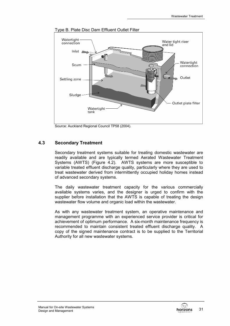
Type B. Plate Disc Dam Effluent Outlet Filter
Source: Auckland Regional Council TP58 (2004).
4.3 Secondary Treatment
Secondary treatment systems suitable for treating domestic wastewater are readily available and are typically termed Aerated Wastewater Treatment Systems (AWTS) (Figure 4.2). AWTS systems are more susceptible to variable treated effluent discharge quality, particularly where they are used to treat wastewater derived from intermittently occupied holiday homes instead of advanced secondary systems. The daily wastewater treatment capacity for the various commercially available systems varies, and the designer is urged to confirm with the supplier before installation that the AWTS is capable of treating the design wastewater flow volume and organic load within the wastewater. As with any wastewater treatment system, an operative maintenance and management programme with an experienced service provider is critical for achievement of optimum performance. A six-month maintenance frequency is recommended to maintain consistent treated effluent discharge quality. A copy of the signed maintenance contract is to be supplied to the Territorial Authority for all new wastewater systems.

Wastewater Treatment
Manual for On-site Wastewater Systems 32 Design and Management
Figure 4.2 Example of an Aerated Wastewater Treatment System
Source: Auckland Regional Council TP58 (2004).
4.4 Advanced Secondary Treatment
Advanced secondary treatment systems include sand filters, textile filters and membrane bioreactor systems. Advanced secondary system performance is typically less affected by intermittent wastewater flows.
4.4.1 Sand Filters
Modern sand filter design comprises primary treatment by septic tank, including an effluent outlet filter from which primary treated effluent is timer dose loaded by pump to the surface distribution system and spread across the entire sand filter surface to ensure thin film flow. Failure to ensure even distribution across the entire surface can result in spot loading, which leads to short-circuiting and saturated flow through the sand filter; this causes reduced effluent treatment quality and, in extreme cases, sand filter failure. Timer-dosed systems provide for more effective treatment than sand filters dosed on demand (ie. the pump is operated by float switch or automatic siphon). Timer dosing buffers the daily peak wastewater production in the septic tank and doses the sand filter in a series of controlled doses over 24 hours. On-demand dose loading by float switch operated pump or siphon results in doses being concentrated around peak wastewater production times; this can result in periodic overloading and less effective treatment. It is critical to use graded sand free of fines for sand filters to ensure optimum performance (TP58 (2004) includes sand grade guidance). Sand filters are also termed packed bed reactors. The surface of intermittent sand filters can be covered with porous soils, but recirculating sand filters must be open to enable transfer of air into the filter for maintenance of aerobic conditions; therefore they should never be covered with soil.

Wastewater Treatment
Manual for On-site Wastewater Systems Design and Management 33
4.4.1.1 Intermittent Sand Filters (ISF) Intermittent sand filters are single pass sand filters that are very effective at reducing BOD, TSS, turbidity, ammonia and faecal coliforms. Effluent from the septic tank, including an effluent outlet filter, is dose loaded as frequent small doses onto the sand filter surface. Applied effluent makes a single pass through the graded sand bed, is collected via under drains, and discharged to the treated effluent tank for land disposal (Figure 4.3). Design parameters for intermittent sand filters are provided in Table 4.3. Table 4.3 Intermittent Sand Filter
Intermittent Sand Filter Design Parameters
Hydraulic loading 40 to 100mm per day Organic loading 0.0025 – 0.01 kg BOD/m2 day Dosing frequency 12 to 48 times per day Effective sand media size (d10) 0.25 – 0.75 mm Uniformity Coefficient (UC) < 4 typically 3.5 Sand depth 600mm – 900mm Notes: 1. The above design application rates are for domestic strength wastewater. 2. Sand must be durable and free of fine silt, clay and organic particles. 3. Effective media size d10 is defined as the 10% size by weight determined by a wet
sieve analysis. 4. Uniformity Coefficient (UC) is d60 divided by d10. UC indicates whether individual
particles are of a similar size or if there is a wide range of particle sizes. Source: Crites and Tchobanoglous (1998)
Figure 4.3 Example Of An intermittent Sand Filter
Source: Auckland Regional Council TP58 (2004).
4.4.1.2 Recirculating Sand Filters (RSF) Recirculating sand filters are multiple pass sand filters (Figure 4.4). They are similar to intermittent sand filters except that part of the treated effluent is mixed with and dilutes primary treated effluent in a recirculation tank, and is then reapplied to the sand filter. Dilution of primary treated effluent allows for a higher loading rate than that for intermittent sand filters. Recirculating sand

Wastewater Treatment
Manual for On-site Wastewater Systems 34 Design and Management
filters are very effective at producing a nitrified effluent low in BOD and TSS. However, sand grain size and the hydraulic and organic loading rate are critical for effective performance. Design parameters for recirculating sand filters are provided in Table 4.4. Table 4.4 Recirculating Sand Filters
Recirculating Sand Filter Design Parameters Hydraulic loading 120 to 200 mm per day Organic loading 0.01 – 0.04 kg BOD/m2 day Dosing frequency 48 to 120 times per day Sand depth 450 mm – 900 mm Effective media size (d10) 1 – 5 mm
Typically 2.5 mm Uniformity Coefficient (UC) < 2.5
Typically 2 Recirculation tank volume Typical 1 day’s flow plus 24 hours’ emergency
storage or gravity to treated effluent tank (TET) chamber.
Treated effluent tank Working volume plus 24 hours flow emergency storage
Notes: 1. The above design rates are for domestic strength wastewater discharged from a
septic tank that includes an effluent outlet filter. 2. Organic and hydraulic loadings are independent variables that depend on the
wastewater source. 3. Sand must be durable and free of fine silt, clay and organic particles. 4. Effective media size d10 is defined as the 10% size by weight determined by a wet
sieve analysis. 5. Uniformity Coefficient (UC) is d60 divided by d10. UC indicates whether individual
particles are of a similar size or if there is a wide range of particle sizes. Source: Crites and Tchobanoglous (1998) Figure 4.4 Example of a Recirculating Sand Filter
Source: Auckland Regional Council TP58 (2004).

Wastewater Treatment
Manual for On-site Wastewater Systems Design and Management 35
4.4.1.3 Bottomless Intermittent Sand Filters Bottomless intermittent sand filters are a combined effluent advanced secondary treatment and land application method; they are covered in section 6.6.
4.4.2 Textile Filters
Textile filters utilise an engineered textile that has a large surface area and high porosity for aerobic treatment of primary treated effluent. The large surface area and porosity allows for a significantly higher loading rate than for sand filters, and therefore a significantly smaller footprint for treatment of a given volume. Primary treated effluent is timer dose loaded from a recirculation tank onto the textile surface and percolates down to a collection system or directly to the recirculation tank. Textile can be in the form of sheets, cubes or coupons (Figure 4.5). A good air flow is important for maximising oxygen transfer to the bacterial film that develops on the textile surfaces. The effective hydraulic and organic loading rate depends on the particular textile filter system, and designers are recommended to apply loading guidelines provided by the equipment suppliers.

Wastewater Treatment
Manual for On-site Wastewater Systems 36 Design and Management
Figure 4.5 Example of a Textile Filter
Source: Auckland Regional Council TP58 (2004).
4.4.3 Membrane Bioreactors (MBR)
Membrane bioreactor (MBR) systems, which use ultra fine membrane filtration and are suitable for treating effluent from individual dwellings, have only recently become available. Typically, an MBR system comprises a primary treatment chamber from which wastewater is discharged to the MBR filtration chamber. The filtration chamber contains the submerged flat membrane panels. Air blowers located below the membrane panels generate an upward flow of wastewater over the membrane panel surface, and help to reduce clogging of the filtration surfaces. The panels are located below the water surface to provide the head necessary for the effluent to pass through the membrane into the hollow central section of the panel. Permeate from the hollow centred panel is then discharged to the treated effluent tank. In operation, the membrane panels have an effective pore size of less than 0.01 micron (ultra filtration), and may remove viruses and pathogenic micro-organisms prior to discharge. Activated sludge that accumulates in the MBR

Wastewater Treatment
Manual for On-site Wastewater Systems Design and Management 37
filtration chamber is recycled back to the primary treatment septic chamber to achieve partial denitrification. It is recommended that designers use the supplier’s design services when sizing these systems.
4.5 Tertiary Treatment
Tertiary treatment refers to additional treatment comprising disinfection for microbiological reduction and/or nutrient reduction following secondary treatment.
4.5.1 Disinfection
Designers are reminded that disinfection does not remove all micro-organisms from the effluent but it should limit their ability to reproduce.
4.5.1.1 Chlorine Chlorine is the most common disinfection method because: • it is effective; and • the chlorine residual is easily monitored. Effluent is not recommended to be chlorinated prior to discharge to land because the chlorine reacts with organic contaminants to form chlorination by-products including organochlorines. Some of the chlorine by-products are carcinogenic and can have cumulative effects on the environment. These risks are considered acceptable where the benefits to public health outweigh the potential environmental risks and are unlikely to be an issue with on-site systems. Effluent that has been treated to advanced secondary level, and thus has a very low organic content, is more readily disinfected using chlorine than effluent having a high organic content. Low organic content effluent has a lower chlorine demand than high organic content effluent, and therefore a reduced chlorine requirement. Common chlorination methods include: • chlorine tablet ablation; and • automated flow proportionate chlorine dosing. The use of tablet chlorination is considered to be unreliable as the level of chlorine addition is not controlled and not related to the actual dose requirement to achieve a 0.5g/m3 chlorine residual. To ensure effective disinfection requires a freely available chlorine (FAC) or chlorine residual of at least 0.5 g/m3 and a minimum contact time of 30 minutes. An advantage of chlorine disinfection is that the chlorine residual and disinfection effectiveness is readily monitored. The most effective chlorination method comprises a chlorine contact tank, chlorine dosing system, mixing system, redox probe or chlorine probe to

Wastewater Treatment
Manual for On-site Wastewater Systems 38 Design and Management
monitor the chlorine residual, and alarms to monitor the chlorine residual in the contact tank and the volume of chlorine remaining in the holding tank.
4.5.1.2 Ultraviolet Light (UV) Disinfection Ultraviolet disinfection utilises UV radiation to penetrate cell walls and disrupt the nucleic acids and prevent reproduction. The advantage of UV disinfection over chlorination is that UV disinfection does not result in formation of toxic by-products. However, the effectiveness of UV disinfection is more difficult to monitor than chlorination. The most effective UV disinfection depends on the effluent quality and is best achieved with effluent that has low suspended solids and turbidity. Suspended solids provide protection for bacteria by shading and also a media for attachment, thus resulting in ineffective disinfection. Effluent should be treated to at least secondary quality but may require additional filtration for effective UV disinfection. UV disinfection systems typically comprise mercury arc bulbs that provide the UV source.
4.5.1.3 Ozone Ozone (O3) is a highly effective oxidant and is more effective than chlorine. However ozonation is an expensive option as it is highly unstable and must be produced on-site.
4.5.2 Nutrient Reduction
Nutrient reduction refers to the reduction in nitrate and phosphates contained within the effluent prior to land disposal.
4.5.2.1 Total Nitrate Reduction Increasing nitrate concentrations within groundwater can impact on human health. Ammonia is highly soluble, easily leached into groundwater and is toxic to aquatic life. The maximum Total Nitrate (TN) content within drinking water recommended by the New Zealand Ministry of Health is 50 g/m3. Nutrients can also stimulate plant and algae growth in surface water and are factors leading to eutrophication. Bacteria that use oxygen from the water to decompose the additional vegetation further degrade water quality for aquatic life. A detailed description of the nitrogen cycle is available in TP58 (2004) section 11.4. Secondary and advanced secondary wastewater treatment systems can be configured to reduce the nitrogen content of the treated effluent. Capacity for nitrate reduction varies significantly between the available on-site wastewater systems. Performance testing of a number of wastewater treatment systems, including their nitrate reduction capability, is being undertaken in Rotorua; the results of the testing regime are available for designers to allow comparisons between systems. This will enable an informed decision when choosing which system to install in a nitrate-sensitive environment.

Wastewater Treatment
Manual for On-site Wastewater Systems Design and Management 39
4.5.2.2 Phosphate Reduction Total phosphorus (TP) in untreated domestic wastewater is about one third in the inorganic soluble form, ie. Dissolved Reactive Phosphorus (DRP), and the remainder is insoluble organic phosphorus. However, most of the insoluble phosphorus converts to DRP after anaerobic processes in a septic tank, and DRP is typically 75% to 90% of the total phosphorus in an effective secondary treatment system. Standard wastewater treatment systems have limited capacity for phosphorus reduction. Any removal that is achieved is from the binding of phosphorus to solids in the effluent and removal of these solids by floatation or settlement. Phosphorus removal or reduction is rarely required for discharge to land application systems within New Zealand because the phosphorus binds to aluminium and iron within the soil. However, phosphorus saturation will occur with time and leaching may follow.
4.6 Pump Chambers and Emergency Storage
A pump chamber is any tank that includes a pump, either within the treatment process or for storing treated effluent prior to discharge to the land application system.
4.6.1 Alarms
Any pump system is to include high water level emergency alarms to alert operators to potential problems within the system should water level rise above the normal operating level. The alarm can be either audible or visual. The visual alarm is to be located in a prominent position so as to be certain it is noticed in the event of activation.
4.6.2 Emergency Storage
There is always a risk of pump failure or disruption to the electricity supply potentially resulting in overflow from the chamber. This risk can be minimised by including at least 24 hours emergency storage in any pump chamber, or by providing overflow to a chamber within the system that has sufficient storage capacity. Emergency storage is to be provided above the high water level alarm and is required to allow time for the maintenance contractor to remedy the problem.
4.7 System Construction Integrity
Construction and installation of a watertight system is critical to the performance of both the treatment stage and land disposal stage. All tankage must be completely watertight to prevent groundwater infiltration and effluent exfiltration. In addition, all risers and lids must be watertight along with all sewer pipes, sewer pipe joints, and tank inlet and outlet pipe connections. Infiltration is an extremely serious problem for any wastewater treatment system and will result in hydraulic loading exceeding the design capacity of the system, potentially leading to catastrophic failure.

Wastewater Treatment
Manual for On-site Wastewater Systems 40 Design and Management
4.8 Greywater
Greywater is wastewater derived from domestic sources within a dwelling, including the shower and bath, hand basins, laundry and kitchen. The minimum wastewater treatment requirement is a septic tank that includes an effluent outlet filter, followed by discharge to a land application system that is appropriately sized according to the daily greywater discharge volume, soil category and land application method. The land application system design is to be based on design for normal domestic wastewater. A greywater collection, treatment and land application system is required where a composting toilet is installed in the dwelling. Proprietary greywater reuse systems are available that take water from the laundry, bathroom and kitchen for irrigation of gardens. However, a dedicated greywater land application system should also be installed for use when garden irrigation is not required.
4.8.1 Greywater Recycling
Greywater recycling refers to systems that treat the greywater and return it to toilet cisterns for flushing. Horizons has health concerns with greywater reuse and is waiting on advice from the Ministry of Health before approving installations in the Region.
4.9 Alternative Wastewater Treatment Systems
The design of composting, vermiculture (use of worms to convert organic wastes to stable soil enriching compounds), peat bed and wetland systems is outside the scope of these guidelines. Specialist design guidelines should be consulted for the design and implementation of these systems.
4.9.1 Composting Toilets
Composting toilets either take all toilet waste or separate the solids and urine. The solids are typically collected in a container that is replaced when full. Waste in the full container is then buried within topsoil to complete the composting process. There are variations on the process described. The success of a composting toilet depends on the commitment of the homeowner and not all homeowners are comfortable with these systems. It is therefore important that sufficient area is available within the property for installation of a full waterborne on-site wastewater treatment and land application system to manage both blackwater and greywater. A resource consent may be required for any composting system and the application is to include a detailed system management plan that details operation, maintenance and compost handling and disposal procedures. Wherever a composting system is installed it will still be necessary to install a greywater treatment and land application system. The greywater system is to be designed in accordance with a domestic system using the per capita flow allowance provided in Table 3.2, and a land application system designed for the design daily greywater production.

Wastewater Treatment
Manual for On-site Wastewater Systems Design and Management 41

Manual for On-site Wastewater Systems Design and Management 42
5. DOSING AND DISTRIBUTION METHODS AND DEVICES
Dosing and distribution methods are defined as the method of discharging effluent from the treatment system to the land application system, and the method for distributing treated effluent within the land application system across the infiltration surface. Historically, systems utilised trickle loading by gravity. However, this potentially can result in creeping failure within the land application system through effluent becoming concentrated at the inlet end of the system and overloading a small area.
5.1 Controlled Loading Devices
Discharge of a set volume of treated effluent by pump or siphon allows for the treated effluent to access the entire length of the land application system distribution line. This is important to ensure the entire design infiltrative surface is utilised rather than the effluent being concentrated on only part of the surface and potentially resulting in creeping failure. Effective distribution ensures the entire infiltration surface is utilised and improves the land treatment potential of applied effluent by soils below the infiltration surface.
5.1.1 Pump-Controlled Dose Loading
Pumped dose loading is preferable to siphon loading as the dose volume and timing of that dose can be controlled to suit the land application system and soils. Pumping also allows the treated effluent produced during the daily peaks to be buffered and discharged evenly over the entire 24 hours as a series of small doses on a timer system; this is in contrast to discharge being concentrated as large doses around the peak times of production.
5.1.2 Siphon-Controlled Dose Loading
Siphon dose loading requires sufficient height difference between the treated effluent tank and land application system to ensure even distribution throughout the distribution pipe(s). A set volume of effluent can be discharged each time the siphon trips. Siphons can only dose on demand, and intermittently overload the infiltrative surface during periods of peak wastewater production over the day.
5.2 Controlled Dose Loading Methods
The treated effluent discharge pump can either be operated on demand or timer controlled.
5.2.1 On-Demand Dose Loading
On-demand dosing can be by siphon or pump operated by a float switch. The disadvantage is that treated effluent discharge is concentrated around the peak time of wastewater production.

Wastewater Treatment
Manual for On-site Wastewater Systems Design and Management 43
5.2.2 Timer-Controlled Dose Loading
Timer dose loading allows control over the volume and timing of each discharge. The advantage is that effluent produced during daily peaks can be buffered in the treated effluent tank (TET) and discharged over the entire day. This can improve the performance of the land application system and land treatment potential of the infiltrated effluent.
5.3 Uncontrolled Gravity Loading
Uncontrolled gravity or trickle loading should only be used where there is no alternative. The disadvantage is that effluent may not be distributed across the entire infiltrative surface, resulting in creeping failure.
5.4 Distribution to the Land Application System
Treated effluent discharged from the TET can either be discharged to load the entire land application system with each dose or to load sections of the system sequentially. It is critical that the distribution pipe to the land application system is watertight so as to exclude groundwater or surface water infiltration and exfiltration of treated wastewater.
5.5 Distribution Methods within the Land Application System
The distribution method within the land application system (trench, bed or mound) refers to the pipe from which effluent is discharged within the land application system. The distribution pipe may be flood loaded via: i. perforated pipe; or ii. slotted pipe, or dose loaded by: i. low pressure effluent distribution pipe; ii. low pressure pipe; or iii. pressure compensating dripper irrigation line. Dose loading by pumping (or siphon) is required to ensure equal loading of the entire distribution system and that effluent is distributed evenly across the entire infiltration surface.
5.5.1 Flood Loading
A land application system is termed to be flood loaded where effluent from the treatment unit is discharged via siphon or pump to a distribution box, with effluent distributed by gravity along the entire length of each trench or bed by a perforated or slotted pipe. It is important that the dose volume is sized to provide distribution along the entire length of individual trenches or bed, taking the pipe diameter and length into account. The length of each trench or bed should not be more than about 15 metres to maximise distribution along the entire trench/bed length.

Dosing and Distribution Methods and Devices
Manual for On-site Wastewater Systems 44 Design and Management
5.5.2 Dose Loading
A land application system is termed to be dose loaded where effluent from the treatment unit is discharged via siphon or pump to an LPP (low pressure pipe), LPED (low pressure effluent distribution) pipe or PCDI (pressure compensating dripper irrigation) pipe within the land application system. Dose loading ensures even distribution along the entire length of distribution pipe or pipes.
5.5.3 Distribution Aggregate
Graded aggregate of a durable material is required within most subsurface land application systems to support the distribution lines, allow effluent to spread across the entire infiltration surface and maintain the integrity of the trench or bed excavation. Only distribution aggregate free of fines is to be used, as any fine will be washed onto and clog the infiltration surface over time, resulting in reduced infiltration capacity and potentially system failure. AS/NZS 1547:2000 recommends an aggregate size range of 20-40 mm. The designer must be aware that different land application methods may require different aggregate grading.

Wastewater Treatment
Manual for On-site Wastewater Systems Design and Management 45

Manual for On-site Wastewater Systems Design and Management 46
6. LAND APPLICATION METHODS
6.1 Discussion
This section provides guidance for selecting the most appropriate on-site land application method and sizing the system based on soil category. A thorough surface and subsurface site assessment (see section 2) must be completed before the most appropriate land application method suited to site soils, environmental constraints and site constraints can be identified, the basal or areal loading rate based on soil category determined, and the system sized. Appropriate loading rates based on soil category, along with a worked design example for each land application method, are provided. A range of land application methods is detailed in this section of the guidelines, including: i. Subsurface pressure compensating dripper irrigation (ssPCDI). ii. Surface pressure compensating dripper irrigation (sPCDI). iii. Shallow narrow trench low pressure effluent distribution (LPED). iv. Standard trenches. v. Conventional beds. vi. Evapotranspiration seepage beds (ETS). vii. Mounds. viii. Bottomless intermittent sand filters. The land application system provides for distribution of treated effluent across the infiltration surface and final land treatment of the wastewater before it merges with groundwater.
6.2 Land Application Area Sizing
The footprint of the primary land application system is based on the peak daily effluent volume to be discharged from the treatment system to the land application system, the type of land application method proposed, and the soil loading rate based on soil category. In addition to the primary system, it is also necessary to set aside a reserve land application area that is to be available for use in the future if required. Reserve land application area requirements are set out in Table 2.3 (page 19). The final selection of a design loading rate for a specific land application method is based on soil category and site and environmental constraints determined from the site assessment. Where environmental or site limitations are significant, it is important for the designer to apply the more conservative loading rate. Horizons does not support the use of increased design loading rates for secondary treated effluent, as provided in AS/NZS 1547:2000. The use of elevated wastewater loading rates reduces the factors of safety required in any design to make allowance for

Land Application Methods
Manual for On-site Wastewater Systems Design and Management 47
unforeseeable wastewater production, soil infiltration capacity and soil moisture variations. It is accepted that primary treated effluent applied to an infiltration surface results in formation of a biological mat that effectively slows the infiltration into the underlying natural soil. However, the literature reports increased risk of inadequate land treatment of effluent if the loading rate is increased to make use of potentially more rapid infiltration. Reduced land treatment leads to increased environmental and public health risks from nutrients and pathogens merging with ground and surface water. Horizons considers that a conservative approach is important for optimal land application system operation. The land application system design infiltration area is calculated on either areal loading or basal loading and detailed for each method.
6.2.1 Areal Loading Rate Design
Areal loading refers to the entire enclosing area of the wastewater land application system. Areal loading rates are applied to shallow subsurface or surface irrigation systems, including: i. Subsurface pressure compensating irrigation systems. ii. Surface pressure compensating irrigation systems. iii. Subsurface shallow narrow trench low pressure effluent distribution
systems (LPED).
6.2.2 Basal Loading Design
Basal loading refers to the basal area only of a land application system. Basal loading rate design is applied to trench and bed systems including: i. Conventional trenches. ii. Conventional beds. iii. Evapotranspiration seepage beds. In addition to the basal loading rate, the designer must also confirm the areal loading rate for the entire land application system enclosing area, including the area between beds and trenches.
6.2.3 Land Application System Method and Design Area Calculation Method
Table 6.1 below sets out the method for calculating the land application area to be used for the land application methods described in this section.

Land Application Methods
Manual for On-site Wastewater Systems 48 Design and Management
Table 6.1 Land Application Area Calculation Method Land Application Method Design Area Calculation Method
Secondary Treated Effluent or Better Pressure compensating dripper irrigation Areal loading
Primary Treated Effluent (Min Septic Tank & Effluent Outlet Filter) LPED shallow trenches Areal loading
Minimum Primary Treated Effluent Conventional trenches Basal loading
Evapotranspiration beds Basal loading Conventional beds Basal loading
Bottomless sand filters Basal loading
6.3 Pressure Compensating Dripper Irrigation
Pressure compensating dripper irrigation (PCDI) refers to the use of small diameter pipe including pressure compensating emitters. Pressure compensating emitters allow for the same volume of treated effluent to be discharged from each emitter, even where the lines are not installed level. The lines must be pressurised by pump to achieve the flow rate required to operate the emitters. PCDI requires a minimum of secondary treated effluent with BOD5:TSS better than 20/30 to minimise the risk of premature line clogging and blockage. Fine filtration of aeration treatment plant effluent may be required in order to minimise solids carry-over to the land application system. In any event, a programmed maintenance schedule should include regular flushing of the lines to remove accumulated material. There are a number of PCDI line suppliers who should be consulted for specific design and installation guidance. Non-pressure compensating irrigation line is also available but must be installed level to achieve even distribution along the entire length of line. It is recommended that designers use pressure compensating irrigation lines in all installations.
6.3.1 Subsurface Pressure Compensating Dripper Irrigation
Subsurface PCDI lines are either mole ploughed or hand trenched into the topsoil zone. The lines should not be placed into poorly drained soils underlying topsoil as this can result in the irrigated effluent tracking along the line. Additional topsoil can be imported and placed over the land application area in the event there is insufficient natural topsoil depth. The maximum recommended depth of installation is 150-200 mm within the aerobic and biologically active surface soils. Extreme care is recommended where it is proposed to sub-irrigate effluent under lawns where the underlying soils are not well drained, and particularly if the lawn is subject to foot traffic. This can result in pugging of the ground surface and effluent ponding. It is preferable that PCDI is placed under garden areas, although care is required when digging the garden subsequently not to cut the lines.

Land Application Methods
Manual for On-site Wastewater Systems Design and Management 49
The advantages of PCDI are: i. Allows irrigation within irregular shaped areas. ii. Allows irrigation in areas that are not practical for trench or bed systems. iii. Lines do not need to be installed level. iv. Allows for widespread distribution over the infiltration area, maximising
land treatment potential. v. Allows for improved control of effluent irrigation. vi. Allows for beneficial reuse of effluent for sub-irrigation of gardens.
6.3.2 Surface Pressure Compensating Dripper Irrigation
Where it is not practical to bury the PCDI lines they can be placed on and pinned to the ground surface. Situations where surface irrigation may be applicable include bushed areas or gardens where public access can be restricted. There is increased risk of run-off from the land application area, particularly on sloping sites. The land application area must be fenced to restrict access.
6.3.3 PCDI Areal Loading Rates
The areal loading rate refers to the disposal of effluent over the entire area enclosed by the irrigation system, including the area between the lines. Recommended areal loading rates for pressure compensating dripper irrigation systems are presented in Table 6.2 below. Table 6.2 Pressure Compensating Drip Irrigation Loading Rates
RECOMMENDED AREAL LOADING RATES FOR PRESSURE COMPENSATING DRIPPER IRRIGATION (PCDI)
Soil Category Areal Loading Rate mm/day
(litres/square metre/day) Category 1 5 (Note 1) Category 2 5 (Note 1) Category 3 4 – 5 (Note 1) Category 4 4 - 5 Category 5 3 - 4 Category 6 2 - 3 (Note 2) Category 7 Note 2
Notes: 1. Pressure compensating dripper irrigation (PCDI) can also be used as an effluent distribution
method within a bed or trench for soils that have good to rapid drainage (Category 1-3 soils). The design loading rate depend on the soil category and land application method employed. The loading rate for bed or trench land application methods is to be calculated on basal rather than areal loading.
2. Special design considerations are required for Category 6 and 7 soils, and where there is limited topsoil depth.
Source: Auckland Regional Council TP58 (2004), and modified.

Land Application Methods
Manual for On-site Wastewater Systems 50 Design and Management
6.3.4 PCDI Head Loss Assessment
PCDI irrigation systems must be dose loaded by pump, although siphon loading may be used where there is sufficient head difference between the treated effluent tank (TET) outlet and uppermost irrigation line. Irrigation line suppliers provide design guidelines for their products. The designer is recommended to calculate the minimum pump head required, ensuring effluent is distributed through the entire irrigation system. Failure to specify sufficient pump head can result in uneven loading and distribution through the entire network, effluent breakout and premature pump failure. An example head loss assessment is provided in Table 6.3.
Table 6.3 Head Loss Calculation Example
PCDI PUMP HEAD LOSS CALCULATION EXAMPLE
Component Head Loss (m) Comments
Emitter 12.0 Minimum pressure required Lateral 0.0 Head loss insignificant
Sub-main 1.0 Using Netafim Ram 17 as a sub-main Main 0.6 (note 3) Using 25 mm LDPE Filter 3.0 Assume blocked filter
Tank depth 2.0 Water meter 1.5 (note 4) Required
Elevation 10 (note 5) Upslope (If downslope include anti-siphon measures). Total
Design Head 30.1m + 10% = 32.11m = 32m
Notes: 1. Based on Netafim design guidelines. 2. Confirm individual headloss values with equipment supplier. 3. Varies depending on length of main. 4. Depends on brand. 5. When pumping downslope always include anti-siphon measures. Elevation is the height
difference between the treated effluent tank (TET) and highest point of the disposal field. If the field is downslope elevation is zero.
6.3.5 Pressure Compensating Dripper Irrigation Design Example
A worked example of a PCDI calculation for determining land application area requirements is provided in Table 6.4 below and a typical layout in Figure 6.1.

Land Application Methods
Manual for On-site Wastewater Systems Design and Management 51
Table 6.4 Pressure Compensating Dripper Irrigation Design Example PRESSURE COMPENSATING DRIPPER IRRIGATION DESIGN EXAMPLE
Peak daily effluent production 900 litres/day Soil category 4 Areal loading rate 3 litres/square metre/day or 3 mm/day
Daily effluent flow (l/d) Areal Loading Rate (l/m2/d)
900 L/d 3 mm
Design land application area 300 m2 (note 1) Reserve land application area (50%) 150 m2
Dimensions Say 10 m x 30 m Linear length of line required (Lines at 1.0 metre centres)
300 linear metres
OR ALTERNATIVELY Linear Length of Line Required
(Lines at 0.5 metre centres)
600 linear metres
(note 2) Notes: 1. Land application areas exclude any setback requirements. 2. The design land application area must remain the same (300 m2) to achieve a 3
mm loading rate and therefore the length of line required is twice that for a 1.0 metre spacing.
6.3.6 PCDI Installation
Irrigation lines are generally installed at 0.3, 0.5 and 1.0 metre centres with the separation distance depending on the soil type. Closer spacings are applicable for slowly draining soils. A wider line spacing may be required where installation is on steeper slopes. The designer should provide the same total length of lines as for a 1.0 metre line separation, even where the line spacing is increased. This is because a reduced line length and reduced number of emitters can overload the soil adjacent to the emitters. The flushing taps for manual flushed installations are to be marked by a permanent stake or toby box so as to allow easy identification for flushing maintenance.
6.3.7 Root Intrusion
Root intrusion via emitters is potentially a problem with aggressive vegetation such as willow tree roots and kikuyu grass. Recent developments in emitter design are claimed to prevent root intrusion. Products available include impregnated herbicide irrigation line or a herbicide dispenser located in-line following the discharge pump. There is still some argument on the scale of the problem and uncertainty over whether root intrusion is actually a significant problem.

Land Application Methods
Manual for On-site Wastewater Systems 52 Design and Management
6.3.8 Maintenance
Maintenance requirements include regular flushing of the irrigation lines to remove any build-up of solids that may develop. Lines should also be inspected (surface or subsurface) for emitter operation. Wet zones can indicate uneven loading resulting from emitter blockage or damaged lines. Figure 6.1 Schematic of a Subsurface Pressure Compensating Dripper
Land Application System
Source: Auckland Regional Council TP58 (2004).
6.3.9 Shallow Trenches and Low Pressure Effluent Distribution (LPED) Shallow and narrow trench systems are 200-250 mm deep by 200 mm wide, backfilled with aggregate and including drilled uPVC pipe nested within slotted draincoil pipe or similar running the length of each trench to provide in-trench effluent distribution (Figure 6.2). The design theory is that side-wall soakage into the aerobic topsoil horizon is maximised to make use of the area between trenches and the evapotranspiration potential from plantings (Table 6.5). The disadvantage of shallow trench systems is that they only provide limited storage potential within the trench. Unless the trenches are installed in high quality organic topsoil that is at least 250 mm deep or within Category 1-3 soils, there is a risk of partially treated effluent breakout onto the ground surface. Extreme care is required with LPED systems discharging into dense and clay dominant soils, as the lateral and downward movement of effluent is restricted and slowed, potentially resulting in surface breakout.

Land Application Methods
Manual for On-site Wastewater Systems Design and Management 53
The concept of LPED can be somewhat confusing as it is both a distribution method within land application systems constructed in Category 1-3 soils (moderate to rapid draining soil) and is also a land application irrigation method utilising narrow shallow trenches and utilising the effective soakage area between trenches. Trenches are typically at 1.5 metre centres but the design areal loading rate is recommended to be applied to only 1 metre and not to the entire 1.5 metres. Although LPED shallow trench systems are installed in Category 4 and 5 soils, it is recommended that pressure compensating dripper irrigation systems and at least secondary effluent treatment be installed in preference. The use of shallow trench systems is not highly recommended in Category 4 or 5 soils due to the inherent risks with this system, unless there is no alternative. Where LPED is used as a distribution method, the design area is to be based on the land application method employed. This is because LPED lines only provide for even distribution along the full trench or bed length. Primary or secondary treated effluent is discharged by pump or siphon to the distribution system comprising Low Pressure Effluent Distribution (LPED) slotted pipe running the entire length of each trench. Trenches are either aggregate or topsoil filled preferably with aggregate. Each LPED line comprises a uPVC 25-30 mm central distribution line nested within slotted pipe or draincoil. Squirt holes drilled into the central pipe are widely spaced, with the spacing calculated specifically for each installation. LPED laterals are dose loaded by pump or siphon via a main header line that has specifically sized orifice plates at the start of each lateral to ensure equal loading of each lateral. LPED systems require careful design and installation to operate effectively. Computer-aided design programmes are available to calculate the orifice plate diameter and squirt hole spacing, based on the length and elevation of each lateral, and it is important that all systems be designed accordingly. Shallow trench LPED design is based on areal loading to utilise the area between trenches for assimilation of the irrigated effluent. Experience has indicated that unless there is an adequate depth (minimum 250 mm) of topsoil with good drainage properties, there is a high risk of land application system failure. LPED is not effective within dense and clay soils as these limit lateral movement of irrigated effluent and potentially result in surface breakout. Extreme caution is required when designing these systems and it is recommended that only very conservative design areal loading rates are applied. The recommended areal loading rate for LPED is 3-5 mm per day, being the entire enclosing area within Category 2 and 3 soils. Pressure compensating dripper irrigation is recommended in preference to LPED methods. Table 6.5 LPED Design Area Worked Example

Land Application Methods
Manual for On-site Wastewater Systems 54 Design and Management
LPED DESIGN EXAMPLE Peak daily effluent production 900 litres/day Soil category 4 Areal loading rate 3 litres/square metre/day or 3 mm/day
Daily effluent flow (l/d) Areal loading rate (l/m2/d)
900 L/d 3 mm
Design land application area (based on 1.0 metre effective area)
300 m2
Reserve land application area 300 m2 Total area required (lines at 1.5 m centres) 450 m2
Linear length of line required ( Lines at 1.0 metre centres)
300 linear metres

Land Application Methods
Manual for On-site Wastewater Systems Design and Management 55
Figure 6.2 Example of a Shallow LPED Land Application System
Note: Trenches can be backfilled with aggregate or topsoil but Horizons’ preference is for aggregate backfill. Source: Auckland Regional Council TP58 (2004).
6.4 Trench Systems
6.4.1 General
Trench land application systems are the conventional method for discharge of treated wastewater into the ground. The choice of the trench disposal system for any site is to be based on the results of the site assessment, taking into account site environmental constraints identified by the site assessment. Trench disposal is better suited to larger blocks of land. The preferred land application method within the Region is pressure compensating dripper irrigation (PCDI). No allowance has been made in the design basal loading rates for increased loading rates for secondary treated effluent.
6.4.2 Conventional Trenches
Conventional trenches are typically 450 mm in depth, backfilled with drainage aggregate and capped with topsoil (Figure 6.3). Effluent is distributed along the entire length of each trench by slotted pipe. Conventional trench design is based on the bottom area of the trench only, which is termed ‘basal loading’. Sidewall loading is not included in the design as this provides a safety factor in the design. The preferred method of loading is by pumping, to ensure even distribution along the entire length of

Land Application Methods
Manual for On-site Wastewater Systems 56 Design and Management
each trench. In any event, a maximum trench length of about 25 metres is recommended. Alternative loading methods include siphon dose loading where sufficient head difference is available between the treated effluent tank outlet and uppermost trench. Trickle gravity loading is not recommended, as even distribution across the entire infiltrative surface cannot be guaranteed. Designers should be aware that when the basal width of the trench exceeds the combined sidewall depth by more than 30%, the system design is to be based on conventional bed basal loading rates applicable for the soil type. Recommended basal loading rates for each soil category are provided in Table 6.6. The table provides a “least conservative” and a “most conservative” loading rate for each soil category in which trench land application is appropriate. On-site wastewater system design is not an exact science and hence a range of loading rates is appropriate to accommodate specific site limiting conditions. Table 6.6 Recommended Design Loading Rates for Conventional Trenches
Basal Loading Rate mm/day
Soil Category
Soil Type
Most Conservative Least Conservative
1 Gravel, coarse sand – Rapid draining
20 (Note 1)
35 (Note 1)
2 Coarse to medium sand – Free draining
20 30
3 Medium fine and loamy sand – Good drainage
20 30
4 Sandy loam, loam and silt loam – Moderate drainage
15 20
5 Sandy clay/loam and silty clay loam – Slowly draining
5 10
6 Sandy clay, non-swelling clay and silty clay – Slowly draining
Trenches not suitable Trenches not suitable
7 Swelling clay, grey clay, hard pan – Poorly or non draining
Trenches not suitable Trenches not suitable
Note: 1. Special design considerations are required for effluent discharge into rapid draining soils.

Land Application Methods
Manual for On-site Wastewater Systems Design and Management 57
Figure 6.3 Typical Conventional Trench Detail
Source: Auckland Regional Council TP58 (2004).
Table 6.7 Conventional Trench Design Example
CONVENTIONAL TRENCH DESIGN EXAMPLE Peak daily effluent production 900 litres/day Soil category 4 Sidewall loading rate 15 litres/square metre/day OR 15 mm/day
Daily effluent flow (l/d) Basal loading rate (l/m2/d)
900 L/day 15 l/m2/d
Design basal land application area = 60 m2 Trench width (metres)
Trench separation (metres) 0.5 m
1.5 m edge to edge (2.0 m centres) Total trench length required
Basal area required (m2) Trench width (m)
Total trench length required
say
= 60 m2
0.5 m
= 120 m total length 5 trenches x 24 m long at 2.0 m centres
Total enclosing area required Trench separation
Total enclosing area (excludes area beyond outer trenches)
2.0 m centres
[4 spaces (between 5 trenches) x 2.0 m + 2 x 0.25 m for half of each outside
trench width not accounted for = 8.5 m x 24 m]
Enclosing area = 204 m2 Reserve basal land application area (min
100%)
204 m2

Land Application Methods
Manual for On-site Wastewater Systems 58 Design and Management
6.5 Beds
6.5.1 Conventional Beds
Beds are the second best alternative to trenches and are only applicable where site topography and site constraints limit trench installation. The design basal loading rate for beds is less than trenches, to account for the reduced sidewall area available for treated effluent lateral infiltration. Bed land application methods should only be applied to Category 1 to 4 soils. Recommended design basal loading rates are provided in Table 6.8. The design area for conventional bed is based on basal loading. The following design criteria are recommended: i. There is at least 1.5 metres separation edge to edge. ii. The maximum width to be 4.0 metres. iii. The maximum length to be about 20 metres. iv. Beds to be dose loaded by pump or siphon. v. Multiple distribution lines to be included where beds are more than
1.5 metres in width. vi. 100% reserve area required.
Table 6.8 Recommended Design Loading Rates for Conventional Beds
Basal Loading Rate mm/day
Soil Category
Soil Type
Most Conservative Least Conservative 1 Gravel, coarse sand –
Rapid draining 20
(note 1) 30
(note 1) 2 Coarse to medium sand –
Free draining 20 30
3 Medium fine and loamy sand – Good drainage
15 20
4 Sandy loam, loam and silt loam – Moderate drainage
10 15
5 Sandy clay/loam and silty clay loam – Slowly draining
Beds not suitable Beds not suitable
6 Sandy clay, non-swelling clay and silty clay – Slowly draining
Beds not suitable Beds not suitable
7 Swelling clay, grey clay, hard pan – Poorly or non draining
Beds not suitable Beds not suitable
Note: 1. Special design considerations are required for effluent discharge into rapid draining soils.

Land Application Methods
Manual for On-site Wastewater Systems Design and Management 59
Table 6.9 Conventional Bed Design Example
CONVENTIONAL BED DESIGN EXAMPLE Peak daily effluent production 900 litres/day Soil category 3 Basal loading rate 20 litres/square metre/day OR 20 mm/day
Daily effluent flow (l/d) Sidewall loading rate (l/m2/d)
900 L/day 20 l/m2/d
Design total sidewall area (m2) = 45 m2 Bed width (m) 1.5 m
Total bed length required Basal area required (m2)
Infiltration area/linear metre (m)
Total bed length required say
45 m2 1.5 m
= 30 m total length
2 beds x 15 m long x 1.5 m wide and 2.0 m edge to edge
Total enclosing area 75 m2
Reserve area required 75 m2
6.5.2 Evapotranspiration (ETS) Beds
ETS beds are for use on sites underlain by Category 5 or 6 soils. They operate on seepage into the soil and evapotranspiration provided by surface vegetation cover. Beds are mounded to promote surface water run-off and minimise rainfall infiltration. Designers must ensure surface water flow is diverted away from the bed. Design basal loading rates are provided in Table 6.10 and a typical ETS bed detail in Figure 6.5. ETS bed design sizing is based on basal loading but includes an allowance for evapotranspiration. The design theory is that the beds may fill during winter when evapotranspiration rates are low, at which time they operate by sidewall and basal seepage alone. The design “areal” loading rate (being the design area plus natural soil between adjacent beds) should not exceed 3 mm/day for primary treated effluent and 5 mm per day for secondary treated effluent. The designer is reminded that lateral seepage of effluent will be restricted by dense soil, requiring a conservative basal loading rate. Recommended design criteria i. Minimum topsoil depth of 250 mm required. ii Minimum treatment by septic tank that includes an effluent outlet filter. iii. Effluent to be dose loaded by pump or siphon. iv. The maximum bed length to be about 20 metres. v. Surface water diversion drains to be installed. vi. A minimum of two beds to be installed. vii. 100% reserve area to be set aside. viii. Multiple distribution lines to be included where beds are more than
1.5 metres in width. ix. Maximum width to be 4.0 metres.

Land Application Methods
Manual for On-site Wastewater Systems 60 Design and Management
x. Minimum separation distance between bed edges to be 1.5 metres. Table 6.10 Recommended Design Loading Rates for ETS Beds
Soil Category ETS Basal Loading Rate (mm/day)
1 Note 1 2 Notes 1 and 2 3 Note 1 and 2 4 12 5 8 to 10 6 5 7 Note 1
Notes: 1. ETS systems are not normally used in Category 1-3 soils and are never used in Category 7
soils. 2. Should ETS beds be used in Category 2 or 3 soils, the basal loading rates for conventional
beds are to be applied.
Table 6.11 ETS Design Example
EVAPOTRANSPIRATION SEEPAGE BED DESIGN EXAMPLE Peak daily effluent production 900 litres/day Soil category 5 Basal loading rate 8 litres/square metre/day OR 8 mm/day
Daily effluent flow (l/d) Basal loading rate (l/m2/d)
900 L/day 8 l/m2/d
Design total basal area (m2) = 112.5 m2 Bed width (m) 1.5 m
Total bed length required Basal area required (m2)
Bed width (m)
Total bed length required say
112.5 m2 1.5 m
= 75 m total length 4 beds x 19 m long x 1.5 m wide

Land Application Methods
Manual for On-site Wastewater Systems Design and Management 61
Figure 6.5 Typical Evapotranspiration Seepage Bed Detail
Note: Filter cloth is not mandatory. Source: TP58 (2004)
6.6 Bottomless Intermittent Sand Filters
Bottomless intermittent sand filters are sand filters that are not lined, thus allowing treated effluent to discharge from the base into the underlying Category 1 or 2 soils. The pre-treatment, design and construction of bottomless sand filters is to be the same as for intermittent sand filters. Wastewater is to be timer dose loaded onto the surface of the sand filter. Flood loading is unacceptable as this does not ensure even distribution across the entire sand filter surface. Recommended sand filter basal loading rates are presented in Table 6.12 below. Bottomless intermittent sand filters and rapid infiltration systems are not encouraged by Horizons. Table 6.12 Recommended Design Loading Rates for Bottomless Intermittent
Sand Filters
Soil Category IBSF Basal Loading Rate (mm/day)
1 50 to 70 2 35 to 50 3 Not suitable 4 Not suitable 5 Not suitable 6 Not suitable 7 Not suitable

Land Application Methods
Manual for On-site Wastewater Systems 62 Design and Management
A 50 mm depth of distribution aggregate should be placed between the natural soil and base of the bottomless sand filter to act as a distribution layer. Table 6.13 Bottomless Sand Filter Design Example
BOTTOMLESS INTERMITTENT SAND FILTER DESIGN EXAMPLE
Peak daily effluent production 900 litres/day
Soil category 2
Basal loading rate 50 litres/square metre/day OR 8 mm/day
Daily effluent flow (l/d) Basal loading rate (l/m2/d)
900 L/day 50 l/m2/d
Design total basal area (m2) = 18 m2
Dimensions say 4.25 m x 4.25 m
6.7 Wisconsin Mounds
Wisconsin mound land application systems are appropriate for construction on slopes of less than 11 degrees that have 450-600 mm of unsaturated topsoil and subsoil overlying a limiting horizon or elevated groundwater table. Construction of mounds on steep slopes (greater than 11 degrees) increases the risk of breakout along the downslope toe and is not recommended. Wisconsin mounds are constructed of graded sand fill, and provide additional renovation of effluent before discharge into the underlying natural soils. The minimum effluent standard for discharge to a Wisconsin mound is by 4,500 litre primary septic tank that includes an effluent outlet filter. Prior to construction of a Wisconsin mound, the natural soils are to be ploughed to allow effluent to infiltrate the natural ground. On flat sites mounds can be constructed as rectangles but on steeper sites they should be as long and narrow as possible along the contour to minimise toe loading. The downslope side of the Wisconsin mound should be extended by design of a toe extending downslope to allow for assimilation of treated effluent moving in the downslope direction. Effluent must be dose loaded by pumping into the mound distribution bed and spread across the entire infiltration surface. TP58 (2004) provides detailed design guidance and a worked example from the Horizons’ Model Design 6 is included below. AS/NZS 1547:2000 provides guidance for construction and installation (section 4.5B).

Land Application Methods
Manual for On-site Wastewater Systems Design and Management 63
6.7.1 Wisconsin Mound Model Design
Model Design 6 – Shallow Moderate to Slow Draining Soils above Hardpan or Shallow Groundwater Improved Septic Tank and Sand Filled Mound (Wisconsin Mound) (source: Horizons Regional Council, 2000). This model design provides for in-mound treatment of septic tank effluent before it disperses into the shallow soil layer above clay hardpan or high water table. Some 300 mm or original soil depth is required.
Model Design For 3 Bedroom Dwelling
• 3 bedrooms • 5 person occupancy • Roof water collection • Per capita flow allowance 140 l/p/d • Daily wastewater production 700 litres
Treatment Unit and Land Application Area Layout System and Mound Details (details for a flat site)
Notes on function

Land Application Methods
Manual for On-site Wastewater Systems 64 Design and Management
1. The 50 mm/day loading rate dosed into the aggregate distribution bed
allows the septic tank effluent to spread sideways by capillary action while seeping slowly through the 600 mm of treatment sand.
2. The resulting high quality effluent spreads into the natural soil and seeps sideways through the soil evenly around the edges of the mound.
Sizing the System to Suit your Soil Type
Soil Conditions Design
Loading Rate
Dosing Lines
Length
Number of Lines
Treatment, Basal and Land
Application Areas
Reserve Area
(100%) Shallow moderate to slow draining soil over hardpan or shallow groundwater
12 mm/day basal area 50 mm/day into aggregate distribution bed.
7.8 m 3 x 30 mm diameter perforated lines in an 1,800 mm distribution bed
Internal treatment area 5.5 m Fill basal area 6.6 m by 12.6 m (83 m2) Land application overall area (1.5 m buffer) 9.6 m by 15.6 m, total 150 sq.m
Length 15.6 m Width 9.6 m Area 150 m2
Notes: 1. 1 mm/day is equivalent to 1 litre of effluent spread over a 1 metre square/day. 2. The 30 mm diameter perforated low pressure dosing lines have shielded perforation holes
and end elbow pieces with a capped riser at top of mound level (as for LPED, Model 1B dosing lines).
Adapting the System for your Household Size
Household Size System Details
Basal and Land Application Area
Size Dwelling: • Two Bedroom • Maximum of 4 persons • Using water conservation fixtures • Daily effluent volume of 450 litres/day Septic Tank Capacity: 3,000 litres
3 lines in 1,200 mm wide distribution bed, 7.5 m length
Basal length 12 m, width 6 m and overall enclosing area 15 m by 9 m, area 135 m2
Dwelling: • Five Bedroom • Maximum 8 persons • 1,120 litres/day Septic Tank Capacity: 4,500 litres
3 lines in 1,800 mm wide distribution bed 12.4 m length
Basal length 17.2 m, width 6.6 m and overall enclosing area 20.2 m by 9.6 m, area 195 m2
Materials Requirement for Basic Household System Quantity 1. Length of 30 mm distribution line 24 m 2. Distribution aggregate 3 m3
3. Filter cloth 14 m2 4. Medium sand fill 31 m3 5. Topsoil cover 11.5 m3
Design Notes

Land Application Methods
Manual for On-site Wastewater Systems Design and Management 65
i. For a different number of household residents, calculate total daily
wastewater effluent output at 140 litres/person/day for rainwater supply, and 180 litres/per/day for bore water or community supply.
ii. To find the mound basal area, divide total daily wastewater output in litres by design loading rate in mm/day. Then allow 600 mm all round for the 3 to 1 slope effect of the 200 mm distribution bed.
iii. Find the overall enclosing area requirement by allowing 1.5 m clearance on either side of the design area (as a buffer), and 1.5 m clearance at each end of the mound.
Pumping Requirements The pump sump to provide storage and pumping cycle provisions to be designed to fit the total daily flow through the selected orifice size and spacing. Installation Notes i. Groundwater or hardpan to be at least 300 mm below the base of the
mound. ii. The natural soil on which the mound is to be placed should be ploughed
or disc ploughed prior to laying the medium sand fill. iii. During installation, the dosing system should be pump tested with clean
water to ensure even distribution is being achieved.
6.8 Land Application Method and Soil Category
Table 6.14 provides a quick reference to allow designers to match a land application method with a soil category when assessing the options available for an on-site land application system design. The designer is reminded that unless a secondary or better wastewater water treatment system plus pressure compensating dripper irrigation land application is installed, it will be necessary to apply to Horizons for a wastewater discharge consent.
6.9 Reserve Land Application Area Requirements
All on-site land application systems are to include a reserve land application area to be set aside for future use in the event the disposal primary area does not perform to design, or wastewater production exceeds design. Minimum reserve area requirements are set out in Table 2.3.

Land Application Methods
Manual for On-site Wastewater Systems Design and Management 66
Table 6.14 Summary Soil Category and Land Application System Compatibility
LAND APPLICATION SYSTEM TYPE
SOIL CATEGORY
1 Gravel
Coarse Sand Rapid
Draining
2 Coarse to
Medium Sand Free Draining
3 Medium Fine and Loamy
Sand Good Drainage
4 Sandy Loam and Silt Loam
Moderate Drainage
5 Sandy Clay Loam Clay
Loam Mod to Slow
Drainage
6 Non-swelling Clay and Silty
Clay Slowly Draining
7 Swelling Clay Poorly or Non
Draining
Pressure compensating drip irrigation (PCDI)
Note 1 Note 1 Note 1 Note 2 Note 2
LPED shallow trenches Note 3 Note 3 Note 3 Discharge control trench Conventional trenches Note 4
Conventional beds Note 4 ETS beds
Wisconsin mounds Bottomless sand filter
Notes: 1. PCDI can also be used as an effluent distribution method within a bed or trench for soils that have good to rapid drainage (Category 1-3). In the case of bed
or trench systems the loading rate is to be calculated on basal rather than areal loading. 2. Specific design required within Category 6 and 7 soils and where there is limited topsoil depth. 3. LPED becomes a distribution method within Category 1-3 soils. 4. Special design considerations required in Category 1 soils. Source: Auckland Regional Council TP58 (2004) with minor modifications.

Land Application Methods
Manual for On-site Wastewater Systems Design and Management 67

Manual for On-site Wastewater Systems Design and Management 68
7. MAINTENANCE AND MANAGEMENT
7.1 Management Plan
The system supplier/installer should provide the system owner with a management plan that provides guidance on action to be taken in the event of an alarm sounding or other system malfunction. The plan should also include all contact details for the supplier, electrician, installer and maintenance provider.
7.2 Maintenance Contract
All on-site and decentralised wastewater treatment and land application systems require regular monitoring and maintenance to ensure ongoing optimum performance. The Regional Rules for Permitted Activities require all new systems to have an operative maintenance contract with the installer, system supplier or suitably qualified and experienced service provider. The frequency of maintenance inspections depends on the system type but should be completed at least six monthly. The maintenance contract should clearly list all items that are specific to the individual systems that will be inspected during the site visit. Inspections should include a visual appraisal of both the treatment system and land application system, noting any evidence of breakout or effluent pooling for rectification, and operation of pumps and alarms where installed. Comment on recent weather/rainfall is also useful to assist in the assessment of the land application system. A copy of the signed maintenance contract is to be provided to the relevant Territorial Authority.
7.3 Owner Education
It is critical that the wastewater system owners understand their role in the successful operation and performance of an on-site system. Performance of a wastewater treatment system and land application system is greatly affected by the owners’ water use management. For example, the average washing machine wastewater production is 22 % of the daily total. However, daily wastewater production derived from clothes washing can be significantly higher where all the use is on one or two days over a weekend. This can result in overloading of the treatment and land application system unless there is adequate buffering in the system. It is critical that the homeowner understands the implications of concentrated use of high water consumption appliances over a short time period, and that such use is moderated. The owner is also responsible for maintaining vegetation within the wastewater disposal area and ensuring surface water diversion drains are clear and able to operate effectively.

Land Application Methods
Manual for On-site Wastewater Systems Design and Management 69
7.4 Operation, Maintenance and Management
A brief summary of minimum requirements for development of a maintenance manual is provided below. Horizons strongly supports owner education to ensure that the owner is aware that all wastewater management is undertaken on-site. Owner education can be initiated by the Territorial Authority LIM report at the time of purchase, which should advise that the site is serviced by an on-site wastewater management system. Owner awareness is critical to the success of any on-site system and the owner must take responsibility for ensuring it is operated and maintained correctly, and does not cause nuisance or risk to public health or the environment. Horizons appreciates that homeowners do not have all the necessary skills for maintenance of an on-site system and to this end requires owners of all new on-site systems to have a current signed maintenance contract with the system supplier, installer or trained maintenance provider. A summary of the critical maintenance requirements of on-site systems is provided below. Modern on-site systems require the maintenance provider to have been trained in the operation, management and maintenance of system. Designers/system manufacturers/installers should supply an Operation and Maintenance Manual specific to the wastewater management system installed on the property. The operation and maintenance manual should include but not be limited to: i. The system specifications. ii. Maximum daily wastewater treatment capacity in litres and dwelling
occupancy numbers. iii. As-built showing the location of all system components. iv. Contact details for the designer and service providers (drainlayer,
electrician, council). v. Any water conservation measures installed in the dwelling. vi. A list of do’s and don’ts for the householder that includes materials that
are not suitable for discharge into the system. vii. Discussion on water use management and impact from overloading the
wastewater system. viii. Maintenance frequency and items requiring checking at each
maintenance milestone. System operation, management and maintenance includes: i. The dwelling’s wastewater producing facilities. ii. Wastewater collection system. iii. Wastewater treatment system. iv. Wastewater delivery system (pipes). v. Wastewater land application system. vi. Land application area vegetation. vii. System monitoring equipment.
7.4.1 Wastewater Production Facilities
All sources of wastewater within the dwelling or institution require ongoing maintenance to ensure wastewater production is minimised: i. Check that taps/shower roses are not dripping. ii. Check that cisterns are not leaking.

Land Application Methods
Manual for On-site Wastewater Systems 70 Design and Management
7.4.1.1 Wastewater Collection System Stormwater can enter the wastewater collection system (sewer pipes) and potentially result in failure of part or all of the wastewater treatment and land application system. i. Ensure that no roof water downpipes discharge stormwater into sewer
gully traps. ii. Ensure that gully traps are proud of ground level to prevent surface
water flow into the sewer. iii. Repair any damaged gully traps.
7.4.1.2 Wastewater Treatment System The wastewater treatment system is a critical component and requires regular maintenance.
7.4.1.3 Existing Treatment Systems
Septic Tanks i. Inspect all lids and vents to ensure no surface water can access the
tank. ii. Ensure all lids are watertight. iii. Ensure all vents are undamaged and in place. iv. Regularly desludge the septic tank (at least every three years or when
the combined depth of sludge and scum occupies 50% of the tank volume/depth).
v. Inspect the effluent outlet filter (if installed) at least once every three months and clean as necessary.
vi. Check high water level/low water level alarm operation. vii. Ensure the discharge pump (where fitted) is operating effectively. viii. Ensure the dosing siphon (where fitted) is operating effectively and not
continuously trickle discharging. ix. Ensure vehicles cannot drive over the tank. Existing Secondary Treatment Systems i. Owners of all secondary or advanced secondary treatment systems
require a current maintenance contract with the system supplier/installer or experience maintenance provider. The systems are to be inspected at least once every six months.
ii. Ensure vehicles cannot drive over the tank.
7.4.1.4 Existing Discharge Systems The discharge system includes all pipe work from the treatment system to the land application area. i. Ensure all pipes to the land application area are undamaged. ii. Ensure any distribution boxes are water tight, lids are securely fitted and
the top is proud of ground level to exclude stormwater.
7.4.1.5 Existing Land Application System
Beds and trenches i. Maintain vegetation cover (mow grass, prevent rank overgrowth, trim
larger vegetation). ii. Ensure large vegetation roots are not blocking distribution pipe work. iii. Keep stock and vehicles clear of the area.

Land Application Methods
Manual for On-site Wastewater Systems Design and Management 71
iv. Ensure all vents are intact and in place. v. Clear all upslope surface water diversion drains and ensure there is no
discharge onto the land application area. vi. Make a visual check for any wet areas that could indicate system failure
or a pipe blockage. vii. Ensure vehicles cannot drive over the area. viii. Ensure all stock are excluded from the area.
7.4.1.6 Existing Pressure Compensating Dripper Irrigation Systems i. Maintain vegetation cover (mow grass, prevent rank overgrowth, trim
larger vegetation). ii. Keep stock and vehicles clear of the area. iii. Ensure all vents are intact and in place. iv. Clear all upslope surface water diversion drains and ensure there is no
discharge onto the land application area. v. Make a visual check for wet areas that could indicate system failure or a
pipe blockage. vi. Flush irrigation laterals at least every six months and preferably every
three months. vii. Check that all laterals are connected to the rising main. viii. Check all valves are operating. ix. Check pressure within the system when operating. x. Check for wet areas that may indicate line breakage/damage, system
failure, and stormwater run-on. xi. Ensure vehicles cannot drive over the area. xii. Ensure all stock are excluded from the area.
7.4.2 Wastewater System Automatic Monitoring Equipment
Modern secondary and advanced secondary systems, and existing older systems include pumps either within the treatment process or/and for pressure discharge of treated effluent to the land application system. Any pump chamber must include a high and low water level alarm. Alarm operation requires regular checking to ensure warning is provided in the event of a pump failing or other failure resulting in a high water level.
7.4.3 New Systems
All owners of new on-site wastewater treatment systems and land application systems are required to have an operative signed maintenance contract with the system installer, manufacturer or suitably qualified maintenance provider. All systems are to be checked at least once every six months.
7.4.4 Alternative Systems
All owners of new on-site wastewater treatment systems and land application systems are required to have an operative signed maintenance contract with the system installer, manufacturer or suitably qualified maintenance provider. All systems are to be checked at least once every six months.

Land Application Methods
Manual for On-site Wastewater Systems 72 Design and Management
7.4.5 Consequences of Inadequate Maintenance
7.4.5.1 In-house Components i. Leaking taps result in excess water production and potential
overloading, and failure of the treatment and land application systems.
7.4.5.2 Gully Traps and Sewer Lines i. Failure of the treatment and land disposal system. ii. Overflow and potential direct contact with partially treated effluent.
7.4.5.3 Treatment System i. System failure resulting in inadequate treatment. ii. Generation of foul odours. iii. Overflow of partially treated effluent from the system creating risk of
direct contact. iv. Public health and environmental risks. v. Impacts on surface water and beaches.
7.4.5.4 Land Application System i. Soil saturation. ii. Generation of foul odours. iii. Pooling/ponding of partially treated effluent on the ground surface. iv. Cross boundary flow. v. Public health and environmental impacts.

Land Application Methods
Manual for On-site Wastewater Systems Design and Management 73

Manual for On-site Wastewater Systems Design and Management 74
8. ASSESSMENT OF EFFECTS ON THE ENVIRONMENT
An assessment of potential effects on the environmental from the proposed land application of wastewater is an essential part of every site assessment. Site assessment requirements are described in Section 2 of this document. The section also includes guidance on minimum separation distance requirements that can be used to support the proposal and Assessment of Environmental Effects (AEE). The AEE should at a minimum include the following: • The anticipated treated effluent quality. • Water conservation measures included in the dwelling. • Impact on surface water (note the separation distance provided in the
design). • Impact on groundwater (note the separation distance between the base of
the land application system and highest seasonal groundwater level). • Flood risk (disposal system to be above the 1:20 year flood (5%) level). A
flood risk assessment may not be required for all proposed systems and Horizons may have existing flood risk information available.
• Impact on soils (based on disposal system loading rate and proposed disposal method).
• Impact on vegetation. • Presence of any historical sites. More comprehensive assessment will be required for larger discharge volumes or in areas with a sensitive environment. Additional details for assessment of environmental effects are available in ARC TP58 (2004) section 11.0.
9. REFERENCES
Auckland Regional Council Technical Publication 58 (TP58) On-Site Wastewater Systems Design and Management Manual (2004).
Crites R. and Tchobanoglous G. (1998) Small and Decentralised Wastewater
Management Systems. McGraw-Hill, Boston, Maine, USA. Horizons Regional Council (2000) On-Site Wastewater System Guidelines for
the Manawatu-Wanganui Region. Standards Australia/Standards New Zealand (2000) Australian/New Zealand
Standard On-site Domestic Wastewater Management AS/NZS 1547:2000. Wellington, New Zealand.
United States Environmental Protection Agency (USEPA) (2002) Onsite
Wastewater Treatment Systems Manual.

Assessment of Effects on the Environment and References
Manual for On-site Wastewater Systems Design and Management 75

Manual for On-site Wastewater Systems Design and Management 76
APPENDIX 1
GLOSSARY OF TERMS


Manual for On-site Wastewater Systems Design and Management 78
Absorption The process by which one substance is taken into and
included within another substance, such as the absorption/uptake of water/effluent by soil or of nutrients by plants.
Activated sludge process
A biological wastewater treatment process by which biologically active sludge (concentrated biomass) is agitated and aerated with incoming wastewater. The activated sludge is subsequently separated from the treated wastewater (mixed liquor) by sedimentation, and most of it is returned to the process. The rest is wasted as needed.
Adsorption The physical or chemical attachment of substances to the surface of soil particles.
Advanced Secondary Treatment
Aerobic biological treatment process, including settling and/or filtering of wastewater. Secondary treated wastewater is expected to be equal to or better than 15 g/m3 five-day biochemical oxygen demand and 15 g/m3 suspended solids. (This is for the purpose of land application. Higher quality, such as 10 gO/m3 and 10 g/m3 respectively or better, may be required where discharge is into water). Systems that can provide advanced secondary treatment are predominantly sand filters, advanced textile filters and packed bed reactors. Some high performing, stabilised and closely monitored aerobic treatment plants (refer AWTS) can also achieve the same discharge quality.
Aerobic Having molecular oxygen as part of the environment, or growing or occurring only in the presence of molecular oxygen (as in "aerobic organisms").
Aerated wastewater treatment plant/system (AWTP or AWTS)
A mechanical on-site treatment unit that provides secondary (biological) wastewater treatment by mixing air (oxygen) and aerobic and facultative microbes with the wastewater, followed by clarification. AWTS systems typically use a suspended growth treatment process similar to activated sludge extended aeration, but can also involve a fixed film (air vented fixed media) biological filtration treatment process, similar to trickling filter. These are also referred to as home aeration plants or household package plants.
All-waste The combined blackwater and greywater flow from a dwelling or premise that is generating domestic waste.
Ammonia (NH4) Un-oxidised form of nitrogen; toxic to aquatic life at elevated concentrations.
Anaerobic Characterised by the absence of molecular oxygen, or growing in the absence of molecular oxygen (as in

Glossary
Manual for On-site Wastewater Systems Design and Management 79
"anaerobic bacteria").
Biochemical Oxygen Demand (BOD)
A commonly used gross measurement of the concentration of biodegradable organic impurities in wastewater. The amount of oxygen, expressed in milligrams per litre (mg/L), required by bacteria while stabilising, digesting, or treating organic matter under aerobic conditions is determined by the availability of material in the wastewater to be used as biological food and the amount of oxygen used by the micro-organisms during oxidation.
Biomat The layer of biological growth and inorganic residue that develops at the wastewater-soil interface and extends up to about 25 mm into the soil matrix. The biomat controls the rate at which pre-treated wastewater moves through the infiltrative surface/zone for coarse to medium textured soils. This growth may not control fluxes through fine clay soils, which are more restrictive to wastewater flows than the biomat.
Blackwater Liquid and solid human body waste and the carriage waters generated through toilet usage.
Best Practicable Option (BPO)
The option for wastewater servicing and/or treatment and/or disposal that best meets public health, environmental and economic objectives.
Building consent A permit issued or authorised by the regulatory authority that allows the installation of wastewater treatment system in accordance with approved plans and disposal codes.
Centralised Wastewater Treatment System (CWTS)
The collection of wastewater from homes and commercial facilities in urban area consisting of collection sewers with a centralised treatment and disposal/reuse facility, usually remote from its source or the community.
Chemical Oxygen Demand (COD)
A measure of oxygen use equivalent to the portion of organic matter that is susceptible to oxidation by a strong chemical oxidising agent.
Chlorine residual The total amount of chlorine remaining in water, sewage, or industrial wastes at the end of a specified contact period following disinfection.
Clarifiers Settling tanks that typically remove settleable solids by gravity.
Clay A textured class of soils consisting of particles less than 0.002 mm in diameter.
Coliform bacteria A group of bacteria predominantly inhabiting the intestines of humans or other warm-blooded animals, but also occasionally found elsewhere. Used as an indicator of

Glossary
Manual for On-site Wastewater Systems 80 Design and Management
human faecal contamination.
Colloids The solids fraction that is described as the finely divided suspended matter that will not settle by gravity and yet is too large to be considered dissolved matter.
Decentralised Wastewater Treatment System (DWTS)
The collection, treatment and disposal/reuse of limited volumes of wastewater, generally from a cluster(s) of dwellings and/or accommodation facilities that are usually located relatively close together, with the wastewater system relatively close to the source (also referred to as "community", "neighbourhood" or "cluster" systems).
Deep bores Deep bores are a form of deep infiltration system, typically around 6 metres deep, used on sites where low permeability surface soils, such as poorly draining clays, are underlain by more permeable subsoil layers at depth.
Denitrification The biochemical reduction of nitrate or nitrite to gaseous molecular nitrogen, or to an oxide of nitrogen.
Design Irrigation Rate (DIR)
The loading rate that applies to the irrigation of a land application area with effluent of a secondary quality. It is expressed in L/m2/week or mm/week. If a spray irrigation system is used, the secondary effluent is subject to continuous disinfection.
Desludging Removal of the accumulated sludge and scum from the septic tank.
Disinfection The process of destroying pathogenic and other micro-organisms in wastewater, typically through treatment by chlorine compounds, ultraviolet light, iodine, ozone, and the like.
Disposal method The type of land application system (dripper irrigation, trench, bed, mound) sized to the daily wastewater flow and wastewater loading rate for dispersal of treated wastewater into the ground for final treatment.
Dissolved Oxygen (DO) The oxygen dissolved in water, wastewater or other liquid, usually expressed in milligrams per litre (mg/L), parts per million (ppm), or percent of saturation.
Dissolved solids The fraction of solids dissolved in water.
Distribution method The pipe system within the land application system to distribute treated wastewater onto the design infiltration area.
Domestic wastewater Wastewater originating from households or personal activities, including water closets, urinals, kitchens, bathrooms and laundries. Includes such wastewater flows from facilities serving staff/employees/residents in

Glossary
Manual for On-site Wastewater Systems Design and Management 81
institutional, commercial and industrial establishments, but excluding commercial and industrial wastes, large-scale laundry activities and any stormwater flows.
Drainage An indication of the local soil wetness conditions likely to occur in most years. Soil wetness is further described as very poorly drained, poorly drained, imperfectly drained, moderately well drained, well drained, and rapidly drained. • Very poorly drained: water is removed from the
soil so slowly that the water table remains at or near the surface for most of the year.
• Poorly drained: All horizons remain wet for the periods of several months.
• Imperfectly drained: Some horizons are wet for periods of several weeks.
• Moderately well drained: Some horizons may remain wet for as long as one week after water addition.
• Well drained: Some horizons may remain wet for several days after water addition.
• Rapidly drained: No horizon is normally wet for more than several hours after water addition.
Dry vault A chamber that receives and treats human and domestic
organic waste using a biological degradation or dehydrating process. The only water used is for cleaning or assisting the biological degradation process.
Effluent Sewage, water, or other liquid that is partially or completely treated, or in its natural state, flowing out of a wastewater treatment system or out of a component of a treatment system.
Effluent filter (also called an outlet filter and an outlet solids control device)
A removable, cleanable device inserted into the outlet piping of the septic tank that is designed to trap excessive solids that are due to tank upsets and that would otherwise be transported to the subsurface wastewater infiltration system or other downstream treatment components.
Engineered design An on-site or cluster system that is designed to meet specific performance requirements for a particular site as certified by a chartered engineer or other qualified person experienced in on-site wastewater treatment and land application systems.
Environment Surroundings, including natural and physical resources, community and neighbourhood relating to health, aesthetic, social, economic and cultural conditions.
Environmental Sensitivity
The relative susceptibility to adverse impacts of a water resource or other environments that may receive wastewater discharges.
Eutrophic A term applied to water that has a concentration of

Glossary
Manual for On-site Wastewater Systems 82 Design and Management
nutrients optimal, or nearly so, for plant or animal growth. In general, nitrogen and phosphorus compounds contribute to eutrophic conditions in coastal and inland fresh waters, respectively.
Evapotranspiration The combined loss of water from a given area and during a specified period of time by evaporation from the soil or water surface and by transpiration from plants.
Evapotranspiration seepage bed
A land disposal system that embodies the principles of evaporation, transpiration and absorption. Also known in Australia as an evapotranspiration absorption trench, bed or area.
Fabric The combination of arrangements of individual soil particles into definable aggregates or peds, which are characterised and classified on the basis of size, shape, and degree of distinctness.
Filter cloth Any durable, permeable textile material suitable for use with soil, rock or earth.
Fixed-film wastewater treatment system
A biological wastewater treatment process that employs a medium such as rock, plastic, wood, or other natural or synthetic solid material that will support biomass on its surface. Fixed film systems include those in which the medium is held in place and is stationary relative to fluid flow, those in which the medium is in motion relative to the wastewater (eg. rotating biological disk), and dual process systems that include both fixed and suspended biomass together or in a series.
Greywater
Domestic wastewater drained from sinks, tubs, showers, baths, dishwashers, clothes washers, and other non-toilet sources. (Greywater should not contain waste from garbage grinders.)
Groundwater The separation distance defined as the vertical distance from the base of the land application system to the highest permanent water table level.
Holding tank A tank used for holding wastewater prior to pumping out.
Hydrologic conductivity
As applied to soils, the ability of the soil to transmit water in liquid form through pores.
Intermittent Packed Bed Reactor
A single-pass sealed reactor media bed (refer Packed Bed Reactor).
Infiltration Passage of water into soil.
Laminar flow Used to describe flat, sheet-like ground water flows that

Glossary
Manual for On-site Wastewater Systems Design and Management 83
migrate laterally along the upper surface of a confining layer of soil or rock.
Land application area Shallow, covered, excavation made in unsaturated soil into which pre-treated wastewater is discharged through distribution piping for application into/onto soil infiltration surfaces through porous media or manufactured (gravel-less) components placed in the excavation. The soil accepts, further treats, and disperses wastewater as it percolates through the soil, ultimately discharging to groundwater.
Land application system (also called application system)
The system used to apply effluent from a wastewater treatment unit into or onto the soils for further in-soil treatment and absorption.
Long term Acceptance Rate
The maximum rate at which a land application system can treat primary or secondary effluent. It allows for loss to the soil by percolation through the base and sidewalls of the disposal system and other losses to the atmosphere by evaporation and evapotranspiration.
Mineralisation The conversion of an element from an organic form to an inorganic state as a result of microbial decomposition.
Mottling Spots or blotches of different colours or shades of colour interspersed with the dominant soil colour, caused in part by exposure to alternating unsaturated and saturated conditions.
Nitrate NO3 The oxidised form of nitrogen, and the form most readily absorbed by plants.
Nitrification The biochemical oxidation of ammonium to nitrate.
On-site Wastewater Treatment System (OWTS)
The collection, treatment, and disposal/reuse of wastewater from an individual home or commercial facility on the same property as it is generated.
Organic nitrogen Nitrogen combined in organic molecules such as proteins and amino acids.
Organic soil Soil that contains a high percentage of organic matter (more than 15-20%) throughout the soil column.
Outlet filter (also called effluent filter)
A removable, cleanable device inserted into the outlet piping of the septic tank that is designed to trap excessive solids arising due to tank upsets and that would otherwise be transported to the subsurface wastewater infiltration system or other downstream treatment components.
Package plant Term commonly used to describe an aerobic treatment unit (refer also AWTS systems) but can include any custom built secondary or advanced secondary treatment system.

Glossary
Manual for On-site Wastewater Systems 84 Design and Management
Can be a standard built plant that has similar design for many sites or custom made and specifically designed to serve a particular situation, eg. involving multiple dwellings or accommodation facilities.
Packed Bed Reactor A sealed reactor media bed (usually layered sand and gravel) with an under-drain collection. Screened effluent is applied to the top of the reactor media in small precise timer controlled doses via a piped distribution system, to provide for a thin film flow through the bed reactor.
Particle size The effective diameter of a particle, usually measured by sedimentation or sieving.
Particle size distribution
The amounts of the various soil size fractions in a soil sample, usually expressed as weight percentage.
Pathogenic Causing disease, commonly applied to micro-organisms that cause infectious disease.
Ped An element of soil structure. Peds are lumps of soil that can be separated from each other by hand. Void spaces between peds control the passage of water through the soil.
Perched water table The permanent or temporary water table of a discontinuous saturated zone in a soil, into which groundwater drains.
Percolation The flow or trickling of a liquid downward through a contact of filtering medium.
Permeability Ability of a porous medium such as soil to transmit fluids or gases.
pH A term used to describe the hydrogen ion activity of a solution which provides a measure of its acidity or basicity.
Plastic soil A soil capable of being moulded or deformed continuously and permanently by relatively moderate pressure.
Platy structure Laminated or flaky soils aggregate developed predominantly along the horizontal axes.
Primary treatment system
The separation of suspended material from wastewater by settlement and/or floatation in septic tanks, primary settling chambers etc. prior to effluent discharge to either a secondary treatment process or to a land application system.
Population equivalent The ratio of the total quantity of wastewater produced to that defined as being equivalent to that produced by one person.
Producer statement A written declaration by a person responsible for an

Glossary
Manual for On-site Wastewater Systems Design and Management 85
activity/product/process, setting out the performance requirements, how these are to be met and the measures required in a assessment of their effectiveness.
Recycle The beneficial reuse of tertiary treated wastewater, usually for toilet flushing purposes only.
Recirculating Packed Bed Reactor
A multiple pass sealed reactor media bed (refer Packed Bed Reactor). The recirculating ratio is typically at 1 to 3 to 1 to 5.
Regulatory authority (RA)
The level of government that establishes and enforces codes related to the permitting, design, placement, installation, operation, maintenance, monitoring, and performance of on-site wastewater treatment systems.
Reserve area An area set aside for future use as a land application area to replace or extend the original land application system.
Residuals The solids generated and retained during the treatment of domestic sewage in treatment system components, including sludge, scum, and pumping from grease traps, septic tanks, aerobic treatment units, and other components of an on-site or cluster system.
Reuse The beneficial reuse of treated wastewater (usually secondary treated) to irrigation lawns and gardens, typically by pressure compensating dripper irrigation.
Sand filter A packed bed filter of sand or other granular materials used to provide advanced secondary treatment of settled wastewater or septic tank effluent. Sand/media filters consist of a lined (eg. impervious PVC liner on sand bedding) excavation or structure filled with uniform washed sand that is placed over an under-drain system. The wastewater is dosed onto the surface of the sand through a distribution network and allowed to percolate through the sand to the under-drain system, which collects the filter effluent for further processing or disposal.
Scum The floating mass of wastewater solids buoyed up by entrained gas, grease or other substances which form an accumulating layer on the liquid surface inside the treatment tank.
Secondary treatment Aerobic biological treatment process, including settling and/or filtering of wastewater. Secondary treated wastewater is expected to be equal to or better than 20 gm five-day biochemical oxygen demand and 30 g/m3 suspended solids. Systems that can provide secondary treatment include well designed and operated, stabilised aerated treatment plants (refer AWTS), usually based on extended aeration activated sludge processes and which can also include sand filters, advanced textile filters,

Glossary
Manual for On-site Wastewater Systems 86 Design and Management
packed bed reactors (refer to Advanced Secondary Treatment Systems).
Septage The liquid, solid and semisolid material that results from wastewater pre-treatment in a septic tank, which is removed from the system by pump-out/desludging operations.
Septic tank A buried, watertight tank designed to receive and partially treat raw wastewater by allowing solids separation from the liquid phase and the decomposition of the retained organic matter by anaerobic bacteria, forming dissolved fatty acids and gases. Settleable solids settle to the bottom, forming a sludge layer, while grease and other light materials float to the top, forming a scum layer. Tanks are normally vented to enable release of the gases generated during liquefaction of the solids.
Sequencing batch reactor
A sequential suspended growth (activated sludge) process in which all major steps occur in the same tank in sequential order. Sequencing batch reactors include intermittent-flow batch reactors and continuous-flow systems.
Setback The distance that a wastewater system must be situated from any facility boundary, water body or other limiting factor.
Settleable solids Matter in wastewater that will not stay in suspension during a designated settling period.
Sewerage The network of collection drains that carry domestic wastewater or effluent away from the properties of origin for off-site treatment.
Silt A textural class of soil consisting of particles between 0.05 and 0.002 millimetres in diameter.
Site assessment An evaluation of site and soil characteristics, and the identification of site constraints. Also includes other environmental, public health, legal and economic factors to be considered prior to the determination of wastewater treatment and land application system options.
Slickensides The skin or coating formed on (usually) large units of soil, which will show striations or grooves resulting from the periodic rubbing together of the soil units due to shrinkage and swelling in response to moisture change.
Sludge The semi-liquid solids settled from wastewater.
Soil absorption zone The volume of soil that is required to filter, isolate and absorb wastewater micro-organisms, nutrients and particles. For normal soils, the zone path length required is at least 0.6-1.2 m. For sandy soils, greater volumes of soil

Glossary
Manual for On-site Wastewater Systems Design and Management 87
may be required.
Soil horizon A layer of soil or soil material approximately parallel to the land surface and different from adjacent layers in physical, chemical, and biological properties or characteristics such as colour, structure, texture, consistence and pH.
Soil map A map showing the distribution of soil types or other soil mapping units in relation to the prominent physical and cultural features of the earth's surface.
Soil morphology The physical constitution, particularly the structural properties, of a soil profile as exhibited by the kinds, thickness and arrangement of the horizons in the profile and by the texture, structure, consistency, and porosity of each horizon.
Soil permeability A calculated value derived from the rate at which a head of liquid is absorbed into soil, usually measured in m/day as Ksat.
Soil survey The systematic examination, description, classification, and mapping of soils in an area.
Soil texture The relative proportions for the various soil separates (eg. silt, clay, sand) in a soil.
Soil water A general term emphasising the physical rather than the chemical properties and behaviour of the soil solution.
Subsoil In general, that part of the soil below the depth of ploughing.
Subsurface Wastewater Infiltration System (SWIS)
An underground system for dispersing and further treating pre-treated wastewater. The SWIS includes the distribution piping/units, any media installed around or below the distribution components, the biomat at the wastewater-soil interface, and the unsaturated soil below.
Terrain-soil map unit An individual mapped area (polygon) that contains a definable slope or group of soils which require individual evaluation prior to use as a land application area.
Textile Packed Bed Reactor (also known as Textile Filter)
A sealed reactor media bed (textile) with an under-drain collection, in which engineered textile media replaces the sand and gravel layers used in other forms of packed bed reactors. The effluent is uniformly dosed through a surface pressure distribution system using a timer-controlled dosing regime.
Topsoil The layer of soil moved in agricultural cultivation.
Total Kjeldahl Nitrogen (TKN)
The sum of the total organic nitrogen component plus ammonia.

Glossary
Manual for On-site Wastewater Systems 88 Design and Management
Total Nitrogen (TN) The sum of the organic nitrogen, ammonia, nitrite and
nitrate.
Unsaturated flow Movement of water in a soil that is not filled to capacity with water.
Wastewater The contaminated water produced from domestic activities in dwellings, institutions, or commercial or public facilities, consisting of all waste, greywater and blackwater. Also defined as foul water in the New Zealand Building Code.
Water quality-based performance requirement
A specific, measurable, and enforceable standard that establishes limits for pollutant concentrations or mass loads in treated wastewater discharged to ground water or surface waters.
Water table The level in saturated soil at which the hydraulic pressure is zero.
Watercourse A stream that: 1. has visible bed and banks, ie. an eroded channel of any size, but not a defined non-eroded grassy course or drainage depression; and 2. is partially fed with water from some source other than or in addition to surface water run-off.
Wetland A system that can provide further treatment of effluent and consists of a bed or rock of other durable media, in which wetland plants are grown.
Source: Auckland Regional Council TP58 (2004).

Glossary
Manual for On-site Wastewater Systems Design and Management 89

Manual for On-site Wastewater Systems Design and Management 90
APPENDIX 2
SOIL DESCRIPTION

Glossary
Manual for On-site Wastewater Systems Design and Management 91

Manual for On-site Wastewater Systems Design and Management 92
SOURCED FROM TP58 (2004) Auckland Regional Council Technical Sheet D-1 ASSESSMENT OF SOIL CHARACTERISTICS FORMATION OF SOILS
Soils are formed as a result of weathering of the parent material from which they are derived. Five key factors determine the nature of the soil profile at any location: • The type of parent material (which determines soil physical and chemical
properties). • Climate, particularly rainfall and seasonal temperature fluctuations, as these
affect the rate and extent of weathering, and also the accumulation and breakdown of organic matter in the soil.
• Living matter such as vegetation and micro-organisms which have significant
influence on the weathering process and contribute to the organic content of soil. • Topography influences the effects of climate; elevated sloping areas drain
better than low lying flat locations; slopes with a northern aspect have higher soil temperatures than those with a southern aspect; steepness affects erosion and deposition of soil layers.
• Soil age affects soil profile; older soils have well-developed profiles compared
to younger soils (the soil forming process evolves over thousands of years of geological time, it being estimated that approximately 100 years of weathering is required to accumulate 25 mm of soil from a parent material).
SOIL TYPE AND PROFILE
The two main types of soils are "mineral" and "organic". Mineral soils are mainly weathered parent material with a small proportion of decayed plant and animal matter. For example, a silt loam soil suitable for plant growth would consist of 45% mineral particles, 5% organic matter, 25% air and 25% water (by volume). Organic soils are those consisting of mainly decayed plant material such as occurs in swamps, bogs, marshland or peat lands. The soil profile consists of the mainly unconsolidated material at the land surface that is utilised for growing crops and supporting structures, and which assimilates and transmits rainfall and constituents of wastes from animal and human activity. Three significant layers make up the soil profile: The A Horizon – comprises the uppermost layer of most weathered material in which the bulk of the physical, chemical and biological activity in the soil takes place. The B Horizon – is a transitional layer to which the very fine particles resulting from weathering will migrate and accumulate (eg. clays). The C Horizon – is the unweathered layer which most resembles the original parent material from which the soil has been formed, and as such is the zone of least activity in the soil.

Soil Description
Manual for On-site Wastewater Systems Design and Management 93
In any soil situation the actual soil profile may be made up of a range of horizons as affected by the time history of soil formation and the combination and dominance of the five soil-forming factors outlined above. SOIL TEXTURE
Texture is determined by the proportions of the three principal mineral size fractions in soil - these fractions are clay, silt, and sand. The United States Department of Agriculture (USDA) classification of size fractions is the most commonly utilised in on-site wastewater practice. The USDA textural classification (Figure D1) is based upon the following particle size ranges: Fraction Particle Diameter mm
Clay less than 0.002 Silt 0.002 to 0.05
Very fine sand 0.05 to 0.10 Fine sand 0.10 to 0.25
Medium sand 0.25 to 0.50 Coarse sand 0.50 to 1.00
Very coarse sand 1.00 to 2.00 Fine gravel > 2. 00
Either laboratory sieve analysis or a field method based upon "feel" of the soil can be used to determine texture. The following explanation of the "feel method" is taken from guidelines prepared by the University of Minnesota Agricultural Extension Service: First, a large marble-sized portion of soil is moistened and then kneaded by hand until it has the consistency of putty. Then, the ball of soil is squeezed between thumb and forefinger so that by pushing the thumb forward over the forefinger a ribbon of soil is formed. The nature of any ribbon that forms (or does not form) indicates the soil textural class. Six general textural classes can be readily distinguishable by this technique – Clay: Fine-textured soil that usually forms hard lumps or clods when dry and is quite plastic when wet. It can be very sticky when wet. When moist it can be squeezed into a long flexible ribbon. A clay soil leaves a "slick" surface when rubbed with a long stroke and firm pressure. Clay also tends to hold thumb and forefinger together due to its stickiness. Clay Loam: Fine textured soil which usually breaks into clods or lumps that are hard when dry. When moist soil is squeezed, it will form a thin ribbon which will break readily, barely sustaining its own weight. The moist soil is plastic and will form a cast which will bear more handling. When hand kneaded it does not crumble readily, but tends to become a heavy, compact mass. Silt Loam: When dry, may appear quite freely cloddy, but lumps are readily broken; when squeezed, it feels soft and floury. When wet, the soil readily runs together. Either dry or moist, it will form casts which can be handled freely without breaking, and when moistened and squeezed, it will not ribbon, but will have a broken effect. Loam: Has a relatively even mixture of sands, silt and clay. A loam feels somewhat gritty, yet fairly smooth and highly plastic. Squeezed when moist, it will form a cast which can be handled quite freely without breaking, and it will not form a ribbon.

Soil Description
Manual for On-site Wastewater Systems 94 Design and Management
Sandy Loam: Contains much sand, but has enough silt and clay to make it somewhat sticky. Individual sand grains can be seen readily and felt. Squeezed when dry, it will form a cast which will fall apart. Squeezed when moist it will form a cast which will bear careful handling without falling apart. Sandy: Loose and single grained. The individual grains can be readily seen or felt. Squeezed in the hand when dry, it will fall apart when the pressure is released and will not form a ribbon. Squeezed when moist, it will form a cast, but will crumble when the pressure is released. Soil texture influences its permeability, aeration potential, and capacity to store water and nutrient salts, all of which affect the soils' ability to assimilate and rejuvenate wastewater components. Soil texture thus has a significant influence on determining design loading rates for on-site systems. SOIL STRUCTURE
The hydrologic conductivity of a soil is significantly affected by its structure. Structure is the aggregation of soil mass into lumps known as "peds" which can be separated from each other by hand. The surfaces of "peds" will be planar in nature and void spaces between "peds" influence the passage of water through the soil, particularly in clayey soils. Common soil structural elements are "prismatic", "columnar", "blocky", "platy", and "granular". Structure may have a more significant effect on water movement in the soil than texture. For example "platy" structures are resistant to vertical water movement, but facilitate horizontal movement. "Blocky" structure in clay soils during dry weather shrinkage can provide high vertical transmission rates, but when wetted and swelled, will resist passage of water. Granular soils tend to be structureless and water movement is solely a function of texture. Aeration of subsoil is also affected by structure as is natural drainage through the subsoil. WATER TABLE DETERMINATION
Soil colour and colour patterns are a good indication of the drainage characteristics of a soil and the seasonal variation in water table. Colour is influenced by the primary soil nature, the level of iron and manganese oxides present, and any organic content. Well drained soils above the water table are generally uniformly red, yellow, or brown in colour. Soils permanently (or nearly permanently) saturated are usually grey or blue in colour. Soils subjected to seasonal saturation can be speckled with different colours, known as mottles. Mottles indicate zones of saturated soil under winter conditions when complex biochemical reactions leach solubilised iron and manganese oxides from the soil, turning it grey in patches. Hence mottled soil under unsaturated conditions indicates periodic saturation. It should be noted, however, that not all soils show mottles under saturation, and landscape position and other soil characteristics may be needed to properly interpret the local situation. Hence, although the water table depth may be fixed by borehole investigation, that result must then be interpreted relative to the season of the year, the degree of soil mottling from the soil profile, and landscape position.

Soil Description
Manual for On-site Wastewater Systems Design and Management 95
SELECTION OF SOIL CATEGORY
The estimation of soil category for design purposes (Section 5.4 of TP58 and Section 4.3 of Appendix E of TP58) should be made on the basis of textural and structural assessment of the soil profile along with all other relevant site information. Traditional on-site practice has been to identify a suitable permeable layer of subsoil at depth below the A Horizon and to construct media filled trench (or bed) systems to load ponded effluent through the base of the trench (or bed) system. It is now recognised that the biologically active A Horizon provides better opportunity for assimilation of effluent organic matter and nutrient salts while at the same time taking advantage of the infiltration and percolation capacity of the underlying subsoil, and the evapo-transpiration potential of planted vegetation. Design techniques which utilise the KISS (keep infiltration systems shallow) approach can take advantage of the disposal capacity of the upper soil/topsoil layer and match the selection of soil category for proposed disposal purposes with the design approach.

Manual for On-site Wastewater Systems Design and Management 96
APPENDIX 3
ON-SITE WASTEWATER DISPOSAL SITE EVALUATION
INVESTIGATION CHECKLIST

Soil Description
Manual for On-site Wastewater Systems Design and Management 97

Manual for On-site Wastewater Systems Design and Management 98
ON-SITE WASTEWATER DISPOSAL SITE EVALUATION INVESTIGATION CHECKLIST (Based on Auckland Regional Council TP58 (2004) Appendix E). PART A: Contact Details 1. Applicant Details: Applicant Name: Company Name First Name(s) Surname Property Owner Name(s)
Nature of Applicant* (*i.e. owner, lessee, prospective purchaser, developer) 2. Consultant/Site Evaluator Details: Consultant/Agent Name Postal Address Phone Number Business Private Mobile Fax Name of Contact Person E-mail Address 3. Are there any previous existing discharge consents relating to this
proposal or other waste discharge/disposal on the site? Yes No (Please tick) If yes, give Reference Number(s) and Description 4. List any other consents in relation to this proposal and indicate whether
or not they have been applied for: If so, specify Application Details and Consent No.): (e.g. water permit, land use consent, subdivision consent)

On-site Wastewater Disposal Site Evaluation
Manual for On-site Wastewater Systems Design and Management 99
PART B: Property Details 1. Property for which this application relates: Physical Address of Property
Territorial Local Authority Regional Council Area
Permitted: Controlled: Discretionary: Legal Status of Activity Relevant Regional Rule(s)
Total Property Area (m2) Map Grid Reference of Property (NZMS 260)
2. Legal description of land (as shown on Certificate of Title): Lot No. DP No. CT No. Other (specify) Please attach copy of Certificate of Title. PART C: Site Assessment: Surface Evaluation Note: Underlined terms defined in section 2 of this manual 1. Has a desk study been undertaken for this property? Yes No (Please
tick) If yes, please specify the findings of the desk study and if not please specify why this was not considered necessary. 2. Has a slope stability assessment been carried out on the property? Yes No (Please
tick) If No, why not?

On-site Wastewater Disposal Site Evaluation
Manual for On-site Wastewater Systems 100 Design and Management
If Yes, please give details of report: Author Company/Agency Date of Report Brief Description of Report Findings
3. Site Characteristics
Provide descriptive details below: Performance of Adjacent Systems: Estimated Rainfall and Seasonal Variation: Vegetation Cover: Slope Shape: Slope Angle: Surface Water Drainage Characteristics: Flooding Potential: YES/NO If yes, specify relevant flood levels on appended site plan, i.e. one in 5 year and/or 20 year and/or 100 year return period flood level, relative to land application area. Surface Water Separation: Site Clearances (Provide general description here and specific dimensions in Part 6 below and on Site Plan: Site Characteristics:

On-site Wastewater Disposal Site Evaluation
Manual for On-site Wastewater Systems Design and Management 101
4. Site geology of the subject property Geological Map Reference Number 5. What aspect(s) does the proposed disposal system face (please tick)? North West North-West South-West North-East South-East East
South
6. Site clearances, which should be also shown on the site plan: Separation distance from Treatment Plant
Separation Distance (m)
Disposal Field Separation Distance
(m) Boundaries Surface Water Stands of Trees/Shrubs Wells, water bores Embankments/retaining walls Buildings Other (specify): PART D: Site Assessment: Subsoil Investigation Note: Underlined terms defined in Table 2. 1. Please identify the soil profile determination method: Test Pit (Depth_____m) No. of Test Pits Bore Hole (Depth_____m) No. of Bore Holes Other (specify)
Soil Report Attached? Yes No (Please Tick)
2. Was fill material intercepted during the subsoil investigation? Yes No (Please
tick) If yes, please specify the effect of the fill on wastewater disposal

On-site Wastewater Disposal Site Evaluation
Manual for On-site Wastewater Systems 102 Design and Management
3. Has percolation testing been carried out? Yes No (Please
tick) If yes, please specify the method Test Report Attached? (Please tick)
Yes No
4. Are surface water interception drains required? Yes No (Please
tick) If Yes, please show on site plan 5. Please state the depth of the seasonal water table: Winter (m) Summer (m)
Please indicate whether measured or estimated (please tick) 6. Are there any potential short circuit paths? Yes No (Please
tick) If yes, please explain how these have been addressed 7. Based on results of subsoil investigation above please indicate the
disposal field soil category Is Topsoil Present? If so, Topsoil Depth? (m) Soil Category
Description Drainage Tick One
1 Gravel, coarse sand Rapid draining 2 Coarse to medium sand Free draining 3 Medium-fine and loamy sand Good drainage 4 Sandy loam, loam and silt loam Moderate drainage 5 Sandy clay-loam, clay loam and silty clay-
loam Moderate to slow drainage
6 Sandy clay, non-swelling clay and silty clay Slow draining 7 Swelling clay, grey clay, hardpan Poorly or non-
draining

On-site Wastewater Disposal Site Evaluation
Manual for On-site Wastewater Systems Design and Management 103
Reasons for placing in stated category PART E: Discharge Details
1. Water supply source for the property (please tick): Bore/well Rainwater (roof collection)
Public supply
2. Calculate the maximum daily volume of wastewater to be discharged,
unless accurate water meter readings are available Number of bedrooms Design Occupancy (number of people) Per capita Wastewater Production
(Litres per person per day)
Other - Specify Total Daily Wastewater Production
(Litres per day)
3. Do you propose to install: a) Water Conservation Devices? Yes No b) Water Recycling – what %? %
No
(Please tick) (Please tick)
If you have answered Yes, please provide additional information including the estimated reduction in water usage: 4. Is Daily Wastewater Discharge Volume more than 2000 litres: Yes No (Please
tick) NOTE: if the answer to the above is Yes a wastewater discharge permit from Horizons Regional Council will be required.

On-site Wastewater Disposal Site Evaluation
Manual for On-site Wastewater Systems 104 Design and Management
5. Is a Horizons Regional Council Discharge Consent Required? Yes No (Please
tick) PART F: Primary Treatment 1. Please indicate below the number and capacity (litres) of all septic tanks
including type (single/dual/grease traps) to be installed or currently existing:
Number of Tanks Type of Tank Capacity of Tank (Litres)
Total Capacity 2. Is a Septic Tank Effluent Outlet Filter to be installed? Yes No (Please
tick)
If Yes, please state the type PART G: Secondary and Tertiary Treatment 1. Please indicate the type of additional treatment, if any, proposed to be
installed in the system (please tick): Secondary Treatment Home aeration plant Commercial aeration plant
Intermittent sand filter Recirculating sand filter Recirculating textile filter
Clarification tank Tertiary Treatment Ultraviolet disinfection Chlorination
Other Specify

On-site Wastewater Disposal Site Evaluation
Manual for On-site Wastewater Systems Design and Management 105
PART H: Disposal Method 1. Please indicate the proposed loading method (please tick): Gravity Pump Dosing Siphon 2. Is a high water level alarm being installed in all pump chambers? Yes No (Please
tick) 3. If a pump is being used, please provide the following information: Total design head (m)
Pump chamber volume (Litres) Emergency storage volume (Litres) 4. Please identify the type(s) of disposal method proposed for this site
(please tick): Surface dripper irrigation Subsurface dripper irrigation Standard trench LPED shallow trench Mound Evapotranspiration beds
Other (please specify) 5. Please identify the loading rate you propose for the option selected in
Part H, Section 4 above stating the reasons for selecting this loading rate Loading rate Land application area Basal Areal
(Litres/m2/day) (m2) (m2)
Explanation

On-site Wastewater Disposal Site Evaluation
Manual for On-site Wastewater Systems 106 Design and Management
6. What is the proposed reserve wastewater disposal area: Reserve land application area (m2) Percentage of primary land application area (%)
7. Please provide a detailed description of the design and dimensions of
the disposal field including a detailed plan of the field relative to the property site:
Description and dimensions of disposal field
Plan Attached Yes No (Please tick) If not explain why not PART I: Maintenance and Management 1. Has a maintenance agreement been made with the treatment and disposal
system suppliers? Yes No (Please
tick) PART J: Assessment of Environmental Effects 1. Is an Assessment of Environmental Effects (AEE) included with the
application? Yes No (Please
tick) 2. Are there any specific environmental constraints? Yes No (Please
tick) If Yes, please explain

On-site Wastewater Disposal Site Evaluation
Manual for On-site Wastewater Systems Design and Management 107
PART K: Is your application complete? 1. In order to provide a complete application have you remembered to: Fully complete this assessment form Include a location plan and site plan (with scale bars)
Enclose a property title (Certificate of Title) Attach an Assessment of Environmental Effects (AEE)
2. Declaration I hereby certify that, to the best of my knowledge and belief, the information given in this application is true and complete.
Name Signature
Position Date