manual for fusion welding of rails by the alumino … · unavoidable circumstances, where rails of...
TRANSCRIPT
GOVERNMENT OF INDIA MINISTRY OF RAILWAYS
MANUAL FOR FUSION WELDING OF RAILS BY THE ALUMINO-THERMIC PROCESS
Revised-2012
Research Designs & Standards Organisation Lucknow-226011
3
CONTENTS
Para No. SUBJECT PAGE
NO. 1. Introduction 1
2. Scope 1
3. Selection of Rail to be welded 1
4. Execution of joints at site 4
5. Operations subsequent to welding 11
6. Acceptance tests 14
7. Sample test joint 16
8. Other requirements 18
9. Precautions 18
10. Defects in A.T. welding 19
11. Check list for inspection of A.T. welds 19
4
LIST OF ANNEXURES
Annexure No. Description PAGE NO.
Annexure-1 Procedure for Training and Certification of 20
Departmental welders by TPP/Lucknow
Annexure-2 List of equipment for Alumino-thermic 22 welding of rail joints by short preheating process per welding team.
Annexure-3 Composition of thermit welding team 25
(compressor tank-wise)
Annexure-4 List of approved suppliers of rail profile 26 weld grinder and weld trimmer
Annexure-5 Proforma for Thermit Weld Register 27
Annexure-6 Procedure for painting of weld collar for 29 thermit welded rail joints to protect against normal corrosion
Annexure-7 Procedure for painting of weld collar for 30
thermit welded rail joints to protect against severe corrosion
Annexure-8 Extracts from IRS:T-19-2012, Clause 4.2 32
on mechanical and metallurgical tests on test welds and retests
Annexure-9 Major defects in A.T. welding because of 36
improper weld execution
Annexure-10 Check list for inspection of A.T. weld 38
Annexure- 11 General guidelines for storage and 40 transportation of A.T. Portion
5
LIST OF FIGURES
Figure No. Description PAGE NO.
Figure 1 Location of marking on non-gauge face of welds 12 Figure 1 of Annexure 8
Location for determination of hardness 32
Figure 3.1 (a) Tolerance on the end bends in the vertical plane 41 Figure 3.1 (b) Tolerance on the end bends in the horizontal 41
plane Figure 3.1 (c) Tolerance on the end bends in the horizontal 41
plane Figure 4.7.1.1(a) Tolerance for lateral misalignment at the time of 42
welding Figure 4.7.1.1(b) Tolerance for lateral misalignment at the time of 42
welding Figure 4.7.1.2 Tolerance for Vertical alignment at the time of 42
welding Figure 5.1 Details of insulation hood 43
Figure 5.4.2 Tolerances on finished welds 44
6
CORRECTION SLIPS
S.No. Correction Slip No.
Date of Issue
Subject Para No(s) affected
Remarks
1
MANUAL FOR FUSION WELDING OF RAILS BY THE ALUMINO-THERMIC PROCESS
1. Introduction
1.1 This manual supercedes “Manual for welding of rail joints by the Alumino-Thermic
process, April 1987”. 1.2 There have been many technological improvements in the process of Alumino-
Thermic (A.T.) welding which have necessitated revision of manual issued in April, 1987 and Feb., 1998. Same considerations also led to revision of Indian Railway Standard specification for fusion welding of rails by Alumino-Thermic process which has now been revised and issued under the serial no. IRS:T-19-2012.
1.3 On Indian Railways Alumino-Thermic welding with short pre-heating process by using
high silica sand mould (carbon dioxide dried) is being followed at present for welding rails of different chemistry and sections. Short pre-heating is mostly being done by air-petrol fuel mixture. Oxy-LPG and compressed air petrol fuel mixture are being developed as these techniques take less time for pre-heating the rail ends to desired temperature resulting in saving of block time with improved quality of joint.
1.4 A.T. welding is required to be done to convert flash butt welded panels into long
panels and for repair of fracture. Normally new single rails shall not be welded by A.T. welding.
1.5 Conventional A.T. welding process which utilised green sand mould has been banned
on Indian Railways. Alumino-thermic welding techniques with short pre-heat process have been standardised for 75R, 90R and higher rail sections and not standardised for 60R rails. The welding of 60R rails will be done by conventional A.T. welding process using green sand mould, as the scope of such welding is very limited for which the provisions laid down in ‘Manual for welding of rail joints by the alumino- thermic process, April 1987’ will continue to be applicable.
2. Scope : This manual outlines the method of welding and the precautions and steps to
be taken before, during and after welding by short pre-heating process for achieving satisfactory weld.
3. Selection of rails to be welded
3.1 For both new as well as second hand rails, before welding, it should be ensured that
the end bends of the rails are within +0.5 mm, -0 mm in vertical and + 0.5 mm in lateral direction, when checked with one metre straight edge as shown in Fig. 3.1(a), (b) and (c).
2
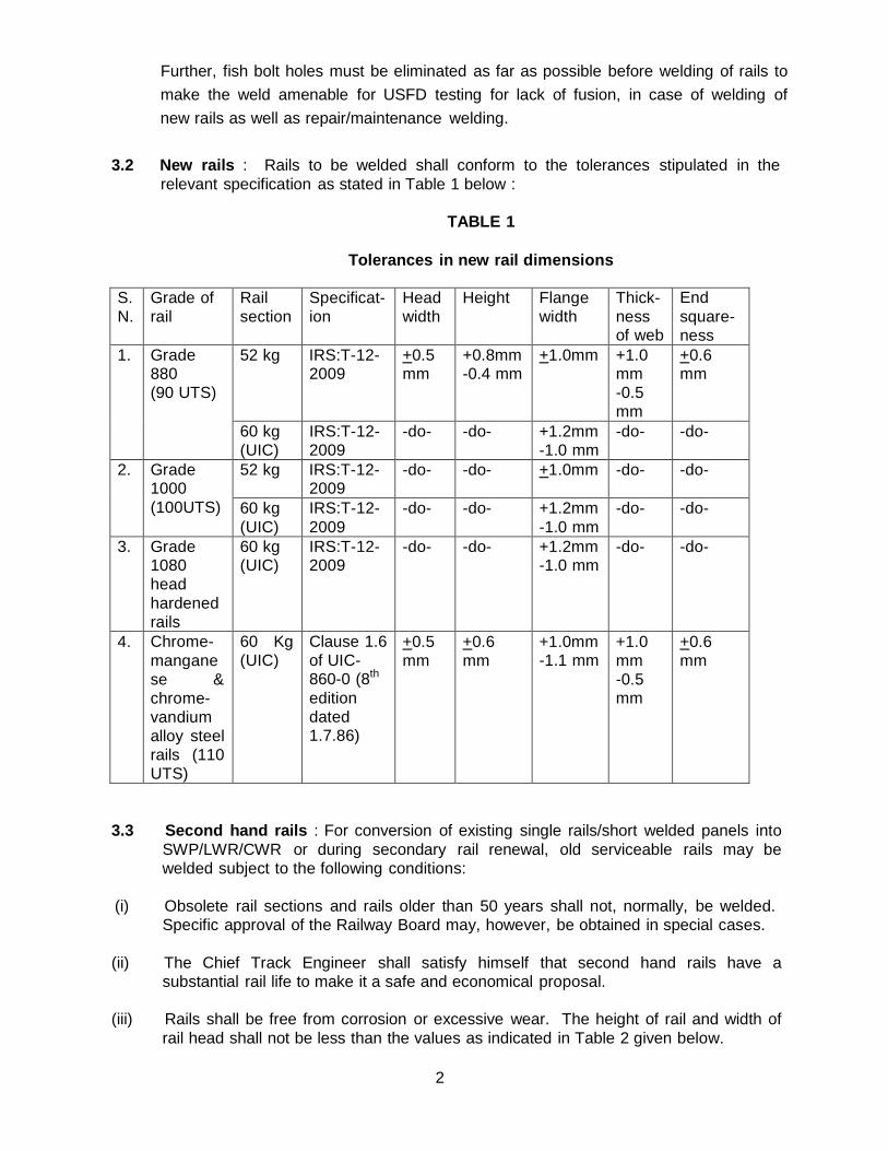
Further, fish bolt holes must be eliminated as far as possible before welding of rails to make the weld amenable for USFD testing for lack of fusion, in case of welding of new rails as well as repair/maintenance welding.
3.2 New rails : Rails to be welded shall conform to the tolerances stipulated in the
relevant specification as stated in Table 1 below :
TABLE 1
Tolerances in new rail dimensions
S. N.
Grade of rail
Rail section
Specificat- ion
Head width
Height Flange width
Thick- ness of web
End square- ness
1. Grade 880 (90 UTS)
52 kg IRS:T-12- 2009
+0.5 mm
+0.8mm -0.4 mm
+1.0mm +1.0 mm -0.5 mm
+0.6 mm
60 kg (UIC)
IRS:T-12- 2009
-do- -do- +1.2mm -1.0 mm
-do- -do-
2. Grade 1000 (100UTS)
52 kg IRS:T-12- 2009
-do- -do- +1.0mm -do- -do-
60 kg (UIC)
IRS:T-12- 2009
-do- -do- +1.2mm -1.0 mm
-do- -do-
3. Grade 1080 head hardened rails
60 kg (UIC)
IRS:T-12- 2009
-do- -do- +1.2mm -1.0 mm
-do- -do-
4. Chrome- mangane se & chrome- vandium alloy steel rails (110 UTS)
60 Kg (UIC)
Clause 1.6 of UIC- 860-0 (8th
edition dated 1.7.86)
+0.5 mm
+0.6 mm
+1.0mm -1.1 mm
+1.0 mm -0.5 mm
+0.6 mm
3.3 Second hand rails : For conversion of existing single rails/short welded panels into
SWP/LWR/CWR or during secondary rail renewal, old serviceable rails may be welded subject to the following conditions:
(i) Obsolete rail sections and rails older than 50 years shall not, normally, be welded.
Specific approval of the Railway Board may, however, be obtained in special cases. (ii) The Chief Track Engineer shall satisfy himself that second hand rails have a
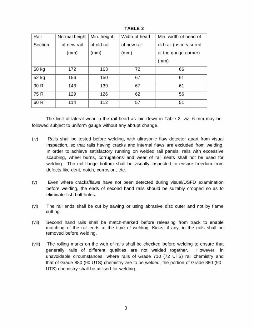
substantial rail life to make it a safe and economical proposal. (iii) Rails shall be free from corrosion or excessive wear. The height of rail and width of
rail head shall not be less than the values as indicated in Table 2 given below.
3
TABLE 2
Rail
Section
Normal height
of new rail
(mm)
Min. height
of old rail
(mm)
Width of head
of new rail
(mm)
Min. width of head of
old rail (as measured
at the gauge corner)
(mm)
60 kg 172 163 72 66
52 kg 156 150 67 61
90 R 143 139 67 61
75 R 129 126 62 56
60 R 114 112 57 51
The limit of lateral wear in the rail head as laid down in Table 2, viz. 6 mm may be followed subject to uniform gauge without any abrupt change.
(iv) Rails shall be tested before welding, with ultrasonic flaw detector apart from visual
inspection, so that rails having cracks and internal flaws are excluded from welding. In order to achieve satisfactory running on welded rail panels, rails with excessive scabbing, wheel burns, corrugations and wear of rail seats shall not be used for welding. The rail flange bottom shall be visually inspected to ensure freedom from defects like dent, notch, corrosion, etc.
(v) Even where cracks/flaws have not been detected during visual/USFD examination
before welding, the ends of second hand rails should be suitably cropped so as to eliminate fish bolt holes.
(vi) The rail ends shall be cut by sawing or using abrasive disc cuter and not by flame
cutting. (vii) Second hand rails shall be match-marked before releasing from track to enable
matching of the rail ends at the time of welding. Kinks, if any, in the rails shall be removed before welding.
(viii) The rolling marks on the web of rails shall be checked before welding to ensure that
generally rails of different qualities are not welded together. However, in unavoidable circumstances, where rails of Grade 710 (72 UTS) rail chemistry and that of Grade 880 (90 UTS) chemistry are to be welded, the portion of Grade 880 (90 UTS) chemistry shall be utilised for welding.
4
(ix) While using second hand rail panels for secondary renewal, released from LWR/CWR sections, the ends should be cropped to eliminate fish bolt holes. If rail ends do not have bolt holes, the ends may be cropped to a distance of minimum 150 mm for A.T. welds and 85 mm for flash butt welds from the center of welded joint to eliminate heat affected zone of welds. End cropping may be suitably increased so as to ensure that rail ends are within the tolerances as specified in para 3.1.
(x) In case of repair of fractured rail/defective weld with wide gap (75mm gap) weld, the
rail shall be cut from center of rail fracture/defective weld 37-38mm each side for making suitable gap of 75mm, provided bolt holes do not fall within 40mm from cut faces.
4. Execution of joints at site
4.1 Technique for welding : Welding techniques approved provisionally or for regular
adoption by Railway Board/RDSO should only be adopted for welding of rails. For details of approved welding techniques and vendors, ‘Master list of approved vendors’ issued biannually by Quality Assurance (Civil) Dte. of RDSO may be referred. Significant advancements have taken place in pre-heating techniques, type of moulds, type of crucibles and process automation in the field of A.T. Welding. These advancements offer significant benefits in terms of service life of A.T. welds. In order to absorb these technological advancements, use of compressed air-petrol or better pre heating, single shot crucible, automatic tapping of molten metal and three piece moulds shall be increasingly used for rails of 52Kg and higher sectional weight with 90UTS and higher grades. Air-petrol pre heating with manual pressurization and/or manual tapping of molten metal and/or use of two piece moulds shall be phased out for such rails.
4.1.1 Thermit welding portions and consumables to be used for welding shall be from
RDSO approved firms only. The list of RDSO approved firms ‘Master list of approved vendors’ is circulated by Quality Assurance (Civil) Directorate of RDSO , bi-annually.
4.1.1.1 Alumino Thermic Welding of Rails may be carried out through any of the following
means: (a) RDSO approved portion manufacturing firms with their own portion, consumables,
equipment and welders/ supervisors. These welders/ supervisors are certified by RDSO. The list of certified welders/supervisors is circulated by M&C Dte. of RDSO annually. In addition, such welders/ supervisors carry a certificate issued by RDSO.
(b) Labour contracting firms with RDSO certified welders/ supervisors with portions and
consumables of Thermit Portion Plant(TPP), NR, Lucknow. The list of such firms is circulated by M&C Dte. of RDSO annually.
5
(c) Departmental welders certified by TPP/Thermit Welding Center (TWC), Vijayawada with TPP portions.
(d) Departmental welders certified by TPP/Thermit Welding Center (TWC), Vijayawada
with Portions, consumables and preferably equipment also, supplied by an RDSO approved portion manufacturer. This is applicable for 25mm gap welding only.
4.1.1.2 In case of turn-key contracts for gauge conversion, new lines, doubling etc. in
which A.T. welding also forms a small portion of the work, suitable provisions shall be kept in the contract conditions for executing the welding by means specified in 4.1.1.1(a) and 4.1.1.1(b) above.
4.1.2 Training and certification of welders :
4.1.2.1 Certification of Welders/Supervisors of Approved portion manufacturing firms shall
be done by RDSO as per provisions of IRST-19-2012, Specification for Fusion Welding of Rails by Alumino Thermic Process.
4.1.2.2 Training and Certification of welders/Supervisors of labour contracting firms shall
be done by RDSO as per provisions of IRST-19-2012, Specifications for Fusion Welding of Rails by Alumino Thermic Process.
4.1.2.3 Training and certification of Departmental welders and supervisors shall be done
by Thermit Portion Plant (TPP), Northern Railway, Lucknow and Thermit Welding Centre (TWC), South Central Railway, Vijayawada as per procedure for certification given in Annexure-1.
4.2 Portion for welding
4.2.1 The portion used for welding shall conform to the technical requirements as
mentioned in IRS:T-19-2012. The suitability of the ‘portion’ for the welding process in respect of the type and section of rails to be welded shall be ensured before commencing welding. Only RDSO certified/passed portions should be used for welding.
4.2.2 Shelf life of portion : No specific shelf life has been indicated for A.T. welding
portions. Life of portions would depend on the quality of packing and storage condition. A.T. portion is sensitive to moisture. Once the portion absorbs moisture, the same cannot be removed even by drying as the ingredients react chemically. All such portion should not be used for welding.
If packing is intact and there is no entry of moisture, the portion can be used even after a long time. However, following procedure may be adopted for permitting use of portions beyond two years after the date of manufacturing :
(a) One random sample per batch of 300 or part there-of may be drawn from the portions
available in stores.
6
(b) The sample shall be tested for reaction test. If the reaction is normal, the batch represented by the sample can be used without further tests.
(c) In case the reaction is found to be quiet or boiling, a test joint should be made from
one more sample selected from the batch. Following tests should be conducted on the test joints.
(i) Weld Metal Chemistry Test
(ii) Load deflection test
These tests should be conducted at Zonal CMTs organisation and/or the Flash Butt Welding Plant. If the values obtained in above tests are within the specified values as given in para 4.1 and 4.2.3.1 of IRS:T-19-2012, the batch represented by the sample can be used otherwise batch should be rejected.
(d) The rejected portions are to be disposed-off by igniting five portions at a time in pit
away from the store. 4.2.3 Storage and transportation of Portions:
‘General guidelines for storage and transportation of A.T. Portion’ representing best practices with respect to storage of materials, are contained in Annexure-11.
4.3 Equipment, staff and Traffic block for welding : The list for one set of A.T. welding equipment by short pre-heating process is given in Annexure 2. The composition of thermit welding team is given in Annexure 3. A minimum traffic block of 70-75 minute duration, depending upon the type of preheating technique adopted, should be obtained for complete operation of welding of first joint and to ensure good quality of A.T. weld.
4.4 Preparation of rail ends to be welded : The rail end face and adjacent sides at foot
(top and bottom), web and head up to 50 mm shall be thoroughly cleaned using kerosene oil and brushing with wire brush to remove all dirt, grease and rust before welding. Any burrs at the rail ends shall be removed by chiseling or grinding.
Normally, no alumino-thermic welded joint shall be located closer than 4 m from any other welded or fish plated joint.
4.5 Gap between rail ends : The two rail ends to be welded shall be held in position with
a uniform and vertical gap as per gap specified for the particular welding technique. The uniformity and verticality of the gap shall be measured by a gauge prior to welding. In case of wide gap 50+1 / 75+1 mm welding, for repairing fractured/defective welds, it shall be ensured that the end faces are vertical. In LWR/CWR territory, hydraulic/mechanical rail tensor of suitable and approved design should be used for maintaining correct rail gap during welding.
7
4.6 Preliminary work prior to welding 4.6.1 In case of in-situ welding the rail fastenings for at least five sleepers on either side
of the proposed weld shall be loosened. The sleepers adjacent to the joint to be welded shall be shifted to obtain a clear working space of 250 mm on either side to accommodate the moulds, clamps, preheating equipment, etc. The rails shall then be properly aligned, both horizontally and vertically.
4.6.2 When the welding work is carried out on cess, full rail length shall be leveled by
supporting on at least ten wooden blocks on either side. The rails shall be properly aligned in horizontal and vertical direction and held in position.
4.7 Alignment of rail ends before welding
4.7.1 The rail ends to be welded shall be aligned in horizontal and vertical planes
to the dimensional limits indicated below :
4.7.1.1 Lateral alignment : The two rail ends, after alignment shall be within +0.5 mm
when checked with a 1.0 m straight edge at rail ends [Fig. 4.7.1.1 (a) & (b)]. Any difference in the widths of rail heads shall always be fully kept on the non-gauge side, correctly aligning the rail ends on the gauge face.
4.7.1.2 Vertical alignment : The joint shall be kept higher by 3 to 4 mm for 72 UTS
rails and 2 to 2.4 mm for higher UTS rails when measured at the end of 1.0m straight edge (as a compensation against sagging caused by differential shrinkage on cooling) (Fig. 4.7.1.2). This shall be achieved by wedges applied on the rail supporting blocks on both sides of the joint.
4.7.2 Gap between rail ends may be rechecked after completion of alignment. Datum
marks shall be made on foot of both rails as well as on joint sleepers in order to observe any longitudinal movement of rails. If excessive longitudinal movement occurs during pre-heating and produces a welding gap outside the prescribed limits, the welding of joint shall be temporarily abandoned and joint allowed to cool.
4.8 Fixing of mould
4.8.1 Only prefabricated moulds supplied by the portion manufacturer shall be used for
welding. These are to be made by mixing high silica sand to IS:1987 with sodium silicate to the required consistency, followed by passage of carbon dioxide gas. The prefabricated moulds shall have adequate permeability for escape of mould gases and adequate reinforcement to avoid mould crushing during transportation and welding.
8
4.8.1.1 Three piece moulds supplied by A.T. portion manufacturer shall conform to ‘Specification of 3 piece Pre-fabricated mould manufactured by A.T. portion manufacturers for use during A.T. welding rails’ given at Annexure -3 of IRS: T-19-2012.”
4.8.2 Before mounting on the rail ends to be welded, each pair of moulds shall be
examined for defects, dampness, cracks, blocked vents, etc. and defective moulds discarded. The prefabricated moulds shall be handled with care as they are fragile and liable to breakage.
4.8.3 During fixing the moulds, it shall be ensured that the center line of the rail gap
coincides with the center line of the mould to avoid cross joint. The mould jackets/shoes holding the pre-fabricated mould in a snug fit condition, after fixing, shall be tightened by the application of adequate pressure. Excessive pressure may cause breakage of mould and dropping of sand inside the mould cavity. Care shall be taken during application of adequate pressure. It is essential for the moulds to fit flush to each other across the bottom of the rail flange which can be checked by feeling with fingers across the junction of the two halves of the moulds and by looking down the riser aperture. The moulds should touch the bottom of rail foot to ensure proper size of collar at the bottom. In case of three piece moulds, care should taken to ensure proper fixing of bottom plate to avoid formation of fin at the edges of bottom flanges of weld.
4.8.4 After fixing the moulds, the gap between mould and the rail shall be packed firmly
with luting sand to prevent leakage of liquid weld metal. To protect the rail top table from metal splashes during reaction, the adjacent rail surface on either side of the moulds shall be covered with metal cover or smeared with luting sand up to 15 cm on either side.
4.9 Preheating
4.9.1 After fixing and luting of the moulds, the rail ends shall be uniformly pre-heated
throughout the rail section with specially designed air petrol/compressed air petrol/Oxygen-LPG burner as the case may be. The flame shall be properly adjusted to achieve the desired rail temperature. The pre-heating shall be done from the top of the mould box for stipulated period for welding technique adopted, so as to achieve a temperature of around 600+200 C.
9
4.9.2 In welding process using Air petrol burner, the compressor tank pressure during operation of the burner shall be maintained at 7+0.70 kg/cm2 (100+10 lb per sq in). For A.T. welding with compressed Air-petrol pre-heating technique, the Air pressure, during operation of the preheating equipment, should be in the range of 0.2 to 0.3 Kg/cm2 . In case of pre-heating by Oxy-LPG process, pressure for oxygen and LPG cylinders shall be adjusted in the range of 7.0-8.0 kg/cm2 and 2.0-2.5 kg/cm2
respectively. While pre-heating with Oxy-LPG burner LPG supply should be opened first and the gas ignited, thereafter oxygen supply should be opened. While closing, oxygen supply should be stopped first followed by LPG supply. The burner shall be properly adjusted during preheating to ensure that the head, web and foot of both rail ends are heated uniformly.
4.9.3 Preheating time : Preheating time would be about 10 to 12 minutes, 4.0 to 4.5
minutes and 2.0 to 2.5 minutes for Air-petrol, compressed Air-petrol and Oxy-LPG preheating techniques respectively. The actual preheating time would depend upon the rail section and welding technique adopted.
4.9.4 Special emphasis shall be given to the tank pressure, efficiency of burner and flame
condition for achieving required rail temperature within the stipulated time. From time to time or in case of any doubt with a view to maintain proper quality control, temperature measuring devices like optical pyrometer, contact type pyrometer or temperature indicating crayons may be used for measuring rail end temperature just after completion of preheating i.e. after removal of burner.
4.10 Welding
4.10.1 The crucible lined with refractory material (magnesite / crushed alumina slag) and
fitted with bottom stone and thimble shall be preheated before making the first weld of the day to ensure freedom from moisture.
4.10.2 Slag shall be cleaned from the crucible after each reaction, if necessary. During
cleaning, care shall be taken not to damage the refractory crucible lining. The lining shall be examined regularly and patch repairing, or relining as necessary shall be carried out.
4.10.3 The crucible shall be positioned relative to the pouring gate with respect to its height
from the mould after it has been placed on the stand mounted on the rail head. The tap hole in the crucible shall be sealed with closing pin, asbestos powder and slag powder. The ‘portion’, for the required technique, shall be thoroughly hand mixed and poured into the crucible striking the crucible wall so that the bottom plugging remains undisturbed. The portion shall be coned to the centre of the crucible and a sparkler be placed at the top. The crucible shall then be brought to the proper position over the mould in line with the pouring gate of the mould with a vertical distance of about 50 mm between the tap hole and sand core/top of the pouring gate.
10
4.10.4 After pre-heating the rail joint, the sparkler shall be ignited and inserted in the portion at the centre top to start the reaction. The reaction shall not be vigorous or boiling. By the time the reaction is complete, the burner shall be removed quickly and the gap closed with a dried sand core in case of central pouring to prevent loss of heat and turbulence during flow of metal. In case of manual tapping, the time period between removal of burner and tapping of metal should be as minimum as possible. After the reaction subsides, about three seconds shall be allowed for the separation of slag from the metal, which may be judged by looking into the crucible through coloured glass to IS:5983 when manual tapping of molten metal is employed. Thereafter, the molten steel shall be tapped into the mould by striking the closing pin with a tapping rod. It shall be ensured that since the commencement of the reaction, thermit steel is tapped within the time limit specified. In case of automatic tapping of molten metal, these aspects are taken care of automatically. Care shall be taken to ensure that the crucible does not move from its position during tapping. When pouring is over, the crucible and swivel stand shall be removed and kept aside without disturbing the joint. If the reaction is found to be boiling, the metal shall be out-tapped. Vigorous reaction and loose closing of crucible may cause self tapping. In this case also, the metal shall be out tapped. If, in any case, self tapped metal enters the mould, the joint shall be rejected, cut and re-welded. In cases of out tapping, the joint should be cooled to ambient temperature and the process of welding restarted afresh. However, if temperature can be measured, the rail ends may be heated to an extent so as to achieve temperature of about 600+200 C and welding of joint may be completed.
4.10.5 After pouring, molten metal shall be allowed to cool and solidify with mould intact for
stipulated time (mould waiting time) depending upon the rail section and ambient temperature. In case of alloy steel rails, full rail section up to 300 mm on either side of the joint shall be heated by using burner during this period. The mould shoes shall be removed just prior to completion of mould waiting time. The mould waiting time is generally four to six minutes for 25 mm gap joints and 12 minutes for 75 mm gap joints. After the mould waiting time has elapsed, the trimming should be done by using weld trimmer of suitable and approved design without knocking out the mould. List of approved suppliers of weld trimmers and rail profile weld grinders as on 22-12-2003 is given at Annexure–4. For current status of firms borne on approved list of Railway Board for small track machines, the latest list circulated by Railway Board may be referred to.
In the eventuality of sudden failure of weld trimmer, manual chipping may be resorted to. In case of welding of old rails, if it is not possible to use weld trimmer due to flow of metal at rail head, manual chipping should be done.
4.10.6 During the trimming operation, it shall be ensured that the wedges used in aligning
are in their proper places without loosening, and they are not removed for at least 20 minutes after stripping. The runner and riser must not be removed until cold, and that too only by knocking towards the rail.
11
4.10.7 No welding shall be carried out if it is raining. In case, the rains start while the joint is under execution, immediate arrangement to adequately cover the site shall be made.
Note: For upgraded A.T. Welding Techniques approved in terms of Part E of
IRS:T:19:2012, the parameters such as preheating time, pressure, type of moulds, crucibles, tapping system etc. shall be mentioned in the approval letter issued by RDSO. These shall be ensured while welding.
5. Operations subsequent to welding
5.1 Post weld cooling
5.1.1 110 UTS alloy steel rail joints (chrome manganese and chrome vanadium type)
are required to be slowly cooled immediately after trimming by fixing an insulation hood (Fig. 5.1) lined with asbestos, so as to control the cooling rate of the weld zone. The hood must be kept around the joint for at least 20 minutes.
5.1.2 In case of welding of head hardened rails, the average hardness of the HAZ of the
rail becomes considerably less than the parent rail hardness. This lower hardness is due to transformation of rail steel occurring at cooling rate much lower than that achieved during the original head hardening operation. Such a hardness difference can lead to differential plastic deformation during wheel rail contact which may cause localized cupping. Head hardened rails, therefore, must be subjected to controlled quenching for a specific time by the arrangement approved for the technique.
5.2 Post weld packing of sleeper: Before the passage of traffic, the wedges used for
aligning should be removed and joint sleepers which were shifted to obtain the clear gap of 250mm on either side as per para 4.6.1 shall be re-shifted to the original location and repacked. Packing of these re-shifted sleepers should be carried out gently and carefully.
5.3 Passing of traffic: The first train should be allowed to pass on the newly welded
joint only after 30 minutes have elapsed since pouring of weld metal. Necessary speed restriction shall be observed until the grinding operation is over.
5.4 Grinding
5.4.1 After the excess metal is trimmed off, the grinding of the remaining metal on
the rail table and the sides of the rail head shall be carried out only with rail profile guided grinding trolley of approved design. Use of hand files should not be resorted to except in unavoidable circumstances. In the case of in-situ joints, the grinding shall commence only after the sleeper fastenings are refixed, after the removal of wedges. The rail table shall first be ground down to original profile and checked by a one metre straight edge. This should be followed by grinding of the sides of the rail head. The accuracy of grinding shall be checked by using 10 cm straight edge. While grinding, only light pressure should be applied and grinding wheel should be moved to and fro to avoid local over heating.
5.4.2 Tolerances on finished welds: All the finished joints shall be checked to ensure
that the joint geometry is within the following tolerances:
12
(i) Vertical alignment : Variation not more than +1.0mm, -0.0mm measured at the end of one metre straight edge.
(ii) Lateral alignment : Variation not more than +0.5mm measured at
centre of one metre straight edge. (iii) Finishing of top surface : +0.4 mm, -0.0mm measured at the end of
10cm straight edge. (iv) Head finishing on sides : + 0.3 mm over gauge side of the rail head
measured at the centre of 10cm straight edge. Note: In specific cases, for joint geometry, in case of old rails, dispensations may be
permitted by Chief Engineer.
The method of checking the geometry of welded joints is illustrated in Fig. 5.4.2. 5.5 Record of joint geometry:The details of geometry of each joint shall be jointly
signed by the firm’s and Railway’s representative and kept as record. Any joint found not conforming to the above stipulations shall be cut and rewelded, free of cost, by the firm.
5.6 TRACEABILITY OF WELDS:
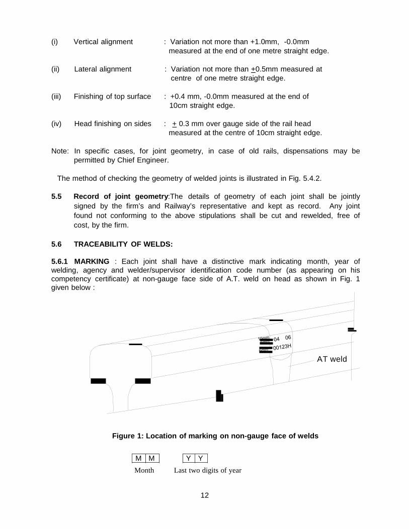
5.6.1 MARKING : Each joint shall have a distinctive mark indicating month, year of welding, agency and welder/supervisor identification code number (as appearing on his competency certificate) at non-gauge face side of A.T. weld on head as shown in Fig. 1 given below :
AT weld
Figure 1: Location of marking on non-gauge face of welds
M M Y Y
Month Last two digits of year
13
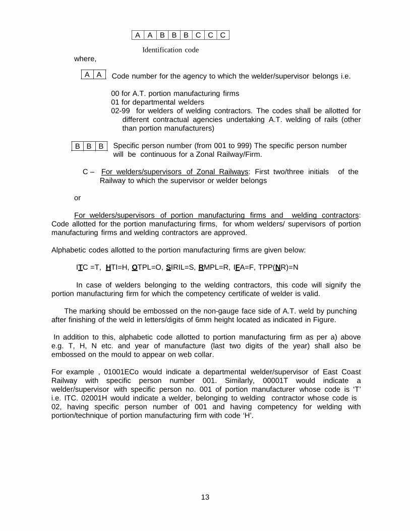
A A B B B C C C
where,
A A
B B B
Identification code Code number for the agency to which the welder/supervisor belongs i.e. 00 for A.T. portion manufacturing firms 01 for departmental welders 02-99 for welders of welding contractors. The codes shall be allotted for
different contractual agencies undertaking A.T. welding of rails (other than portion manufacturers)
Specific person number (from 001 to 999) The specific person number will be continuous for a Zonal Railway/Firm.
C – For welders/supervisors of Zonal Railways: First two/three initials of the
Railway to which the supervisor or welder belongs
or
For welders/supervisors of portion manufacturing firms and welding contractors: Code allotted for the portion manufacturing firms, for whom welders/ supervisors of portion manufacturing firms and welding contractors are approved.
Alphabetic codes allotted to the portion manufacturing firms are given below:
ITC =T, HTI=H, OTPL=O, SIRIL=S, RMPL=R, IFA=F, TPP(NR)=N
In case of welders belonging to the welding contractors, this code will signify the portion manufacturing firm for which the competency certificate of welder is valid.
The marking should be embossed on the non-gauge face side of A.T. weld by punching
after finishing of the weld in letters/digits of 6mm height located as indicated in Figure.
In addition to this, alphabetic code allotted to portion manufacturing firm as per a) above e.g. T, H, N etc. and year of manufacture (last two digits of the year) shall also be embossed on the mould to appear on web collar.
For example , 01001ECo would indicate a departmental welder/supervisor of East Coast Railway with specific person number 001. Similarly, 00001T would indicate a welder/supervisor with specific person no. 001 of portion manufacturer whose code is ‘T’ i.e. ITC. 02001H would indicate a welder, belonging to welding contractor whose code is 02, having specific person number of 001 and having competency for welding with portion/technique of portion manufacturing firm with code ‘H’.
14
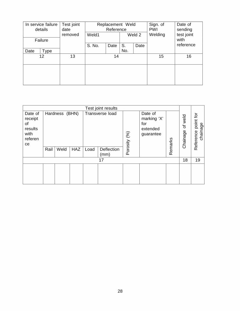
5.6.2 WELD RECORDS:
PWI shall maintain ‘Thermit Weld Register’ as per proforma given in Annexure 5. The welded joints shall be serially numbered in a kilometre. Repair welds/additional welds done at a later date may be given continuing weld number in that kilometre. For example, the last thermit weld number in a particular kilometre was 88 and subsequently a thermit weld has been executed, it shall be numberd 89, irrespective of its location in that kilometre.
5.7 Painting of thermit welds
5.7.1 Painting of weld collar should be done on all welds to protect them against corrosion
immediately after the welding. The procedure of painting and specification of paint is outlined in Annexure 6 and 7.
5.7.2 In service painting (maintenance painting) of thermit welds should be carried as per
following frequency: (i) Once in four years in areas not prone to corrosion.
(ii) Every year at locations prone to corrosion as defined in para 249 (i) of IRPWM. The frequency may be increased depending on the site conditions.
(iii) On condition basis at locations which are prone to severe corrosion (areas of severe corrosion to be decided by territorial Chief Engineer/Chief Track Engineer).
5.7.3 The procedure for painting of weld collar for thermit welded rail joints to protect against normal corrosion and severe corrosion is outlined in Annexure 6 and 7 respectively.
6. Acceptance tests
6.1 Visual inspection : All the welded joints shall be cleaned and examined carefully to
detect any visible defect like cracks, blow holes, shrinkage, mismatch, surface finish (smooth surface finish required) etc. Any joint, which shows visible defect, shall be declared defective.
The bottom of the joint shall be checked by feeling with fingers as well as inspected with the help of a mirror for presence of ‘fins’ at the parting line of the mould. If fin is observed in any joint, the joint shall be declared defective.
6.2 Dimensional check : All finished joints shall be checked for dimensional tolerances
which should be within the tolerances as specified in para 5.4.2.
15
6.3 Ultrasonic flaw detection test : All the fusion welded joints shall be ultrasonically tested as per the provisions of ‘Manual for Ultrasonic testing of rails and welds’. This testing shall be completed as early as possible but in any case before the welding team is shifted. The cumulative number of A.T. welds defective in ultrasonic testing and in other criteria shall be limited to as per clause 7.3.1. A thermit welding done in-situ shall be joggle fish plated with two clamps till tested as good by USFD. (ACS-1)
For upgraded A.T. welding techniques approved in terms of Part E of IRS:T:19:2012, cumulative number of failed A.T. welds in ultrasonic testing and in other criteria shall be limited to as per clause 7.3.1.1
6.3.1 Subsequent USFD testing of A.T. welds shall be done as per the provisions given in Manual for Ultrasonic Testing of Rails and welds, Revised-2012.
Note: For upgraded A.T. welding techniques approved in terms of Part E of IRS:T:19:2012, the A.T. welds shall exhibit less than 0.4% cumulative failure rate during execution, acceptance, acceptance ultrasonic testing and during service upto 120GMT or 3 years whichever is earlier including weld failures and welds declared defective during regular ultrasonic testing up to 120GMT or 3 years of installation whichever is earlier. A penalty of three times the unit rate of supply and execution of joints shall be payable by the firm for each joint failing in above criteria.
6.3.2 Defective/ Fractured joints :
In case, cumulative number of A.T. welds failed in criteria given in clause 7.3.1/ 7.3.1.1 exceed stipulated percentage in respective clauses, following action shall be taken:
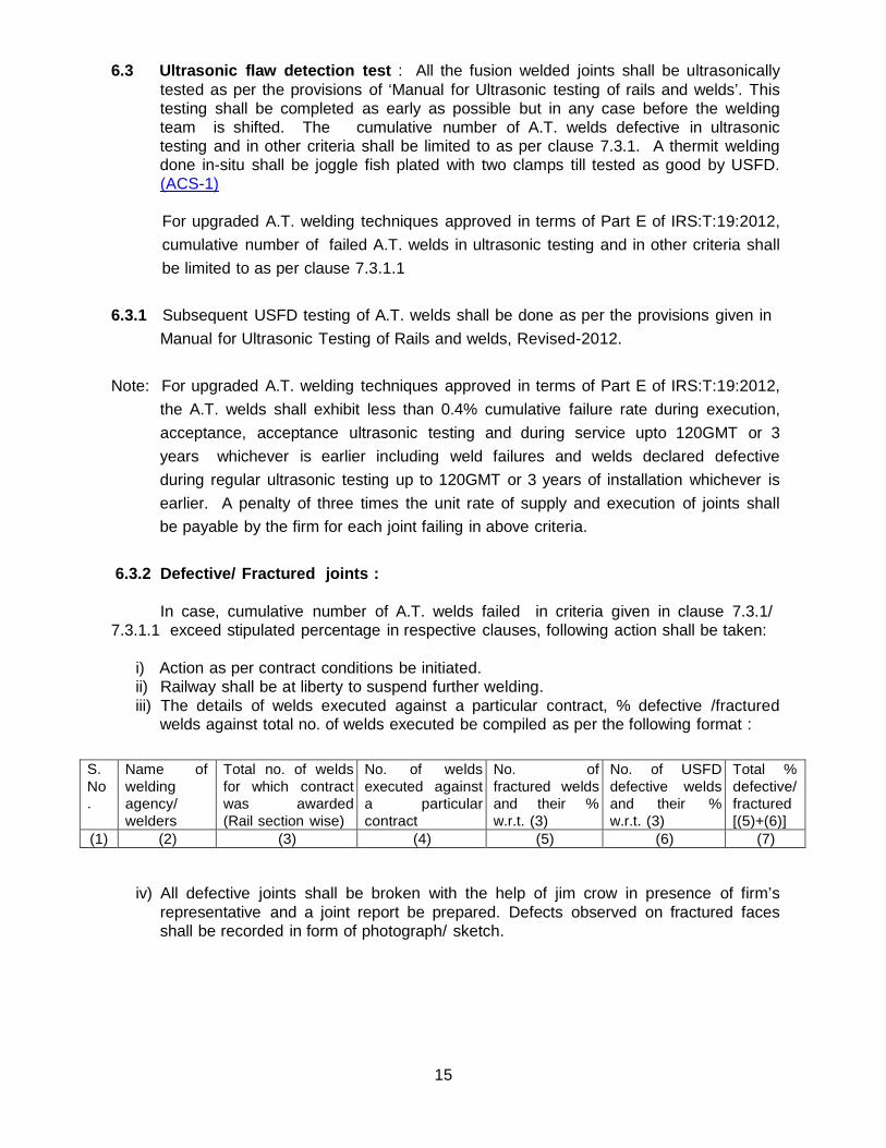
i) Action as per contract conditions be initiated. ii) Railway shall be at liberty to suspend further welding. iii) The details of welds executed against a particular contract, % defective /fractured
welds against total no. of welds executed be compiled as per the following format :
S. No .
Name of welding agency/ welders
Total no. of welds for which contract was awarded (Rail section wise)
No. of welds executed against a particular contract
No. of fractured welds and their % w.r.t. (3)
No. of USFD defective welds and their % w.r.t. (3)
Total % defective/ fractured [(5)+(6)]
(1) (2) (3) (4) (5) (6) (7)
iv) All defective joints shall be broken with the help of jim crow in presence of firm’s representative and a joint report be prepared. Defects observed on fractured faces shall be recorded in form of photograph/ sketch.
16
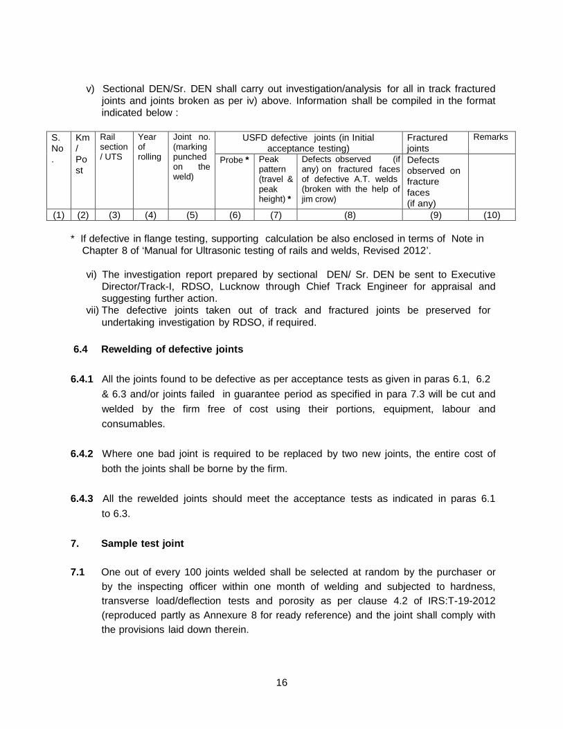
v) Sectional DEN/Sr. DEN shall carry out investigation/analysis for all in track fractured
joints and joints broken as per iv) above. Information shall be compiled in the format indicated below :
S. No .
Km / Po st
Rail section / UTS
Year of rolling
Joint no. (marking punched on the weld)
USFD defective joints (in Initial acceptance testing)
Fractured joints
Remarks
Probe * Peak pattern (travel & peak height) *
Defects observed (if any) on fractured faces of defective A.T. welds (broken with the help of jim crow)
Defects observed on fracture faces (if any)
(1) (2) (3) (4) (5) (6) (7) (8) (9) (10)
* If defective in flange testing, supporting calculation be also enclosed in terms of Note in Chapter 8 of ‘Manual for Ultrasonic testing of rails and welds, Revised 2012’.
vi) The investigation report prepared by sectional DEN/ Sr. DEN be sent to Executive
Director/Track-I, RDSO, Lucknow through Chief Track Engineer for appraisal and suggesting further action.
vii) The defective joints taken out of track and fractured joints be preserved for undertaking investigation by RDSO, if required.
6.4 Rewelding of defective joints
6.4.1 All the joints found to be defective as per acceptance tests as given in paras 6.1, 6.2 & 6.3 and/or joints failed in guarantee period as specified in para 7.3 will be cut and welded by the firm free of cost using their portions, equipment, labour and consumables.
6.4.2 Where one bad joint is required to be replaced by two new joints, the entire cost of both the joints shall be borne by the firm.
6.4.3 All the rewelded joints should meet the acceptance tests as indicated in paras 6.1 to 6.3.
7. Sample test joint
7.1 One out of every 100 joints welded shall be selected at random by the purchaser or by the inspecting officer within one month of welding and subjected to hardness, transverse load/deflection tests and porosity as per clause 4.2 of IRS:T-19-2012 (reproduced partly as Annexure 8 for ready reference) and the joint shall comply with the provisions laid down therein.
17
7.2 If the sample test joint fails to satisfy any of the requirements of specification IRS:T- 19-2012, the Railway will be at liberty to suspend further welding. However, two more randomly selected joints from the same lot of 100 joints shall be subjected to retests as per clause 4.2 of IRS:T-19-2012. Both the joints should clear all the tests. If this report is also not satisfactory, further welding of joints shall be suspended until the firm’s welding technique has been examined and the same satisfies the requirements of clause 4 of IRS:T-19-2012. The clearance for recommencement of welding shall be given by RDSO.
7.3 Guarantee
7.3.1 Rail joints welded by a firm shall be guaranteed against failure which includes
failures in execution, acceptance, acceptance & regular ultrasonic testing and during service up to 2 years from the date of welding the joints in track or from the date such welded joints made ‘in cess’ and inserted in the track are open to traffic. Any such welded joints which fail in the criteria given above within the guarantee period shall be re-welded free of cost by firm as per stipulations of clause 6.4.
However, cumulative number of failed A.T. welds including rewelded joints in criteria given above up to 2 years, shall not exceed 2% of the total quantity of joints in a particular contract. A penalty of three times the rate of supply and execution of joints shall be payable by the firm for each joint failing in above criteria.
7.3.1.1 For upgraded A.T. welding techniques approved in terms of Part E of
IRS:T:19:2012, the joints welded by a firm shall be guaranteed against failure which includes failures in execution, acceptance, acceptance & regular ultrasonic testing and during service up to 120GMT or 3 years whichever is earlier, from the date of welding the joints in track or from the date such welded joints made ‘in cess’ and inserted in the track are open to traffic. Any such welded joints which fail in the criteria given above within the guarantee period shall be re-welded free of cost by firm as per stipulations of clause 6.4.
However, cumulative number of failed A.T. welds including rewelded joints of upgraded A.T. welding technique in criteria given above up to 120 GMT or 3 years whichever is earlier, shall not exceed 0.4% of the total quantity of joints in a particular contract. A penalty of three times the rate of supply and execution of joints shall be payable by the firm for each joint failing in above criteria.
7.3.2 In case of failure of sample test joint (refer para 7), the period of guarantee for 100
joints represented by the sample joint shall be extended for a further period of one year. In case of failure of joints or joints exhibiting signs of failure by cracking within extended period of guarantee, the joints shall be rewelded free of cost by the supplier as per stipulations of para 6.4.
18
7.4 The welded joints with the extended period of guarantee shall be punch marked ‘X’ on the right of markings for month/year in addition to the markings prescribed in Clause 5.6. Such marked joints shall be kept under careful observation by the purchaser.
8. Other requirements
8.1 Welding shall be supervised by trained welding supervisor and carried out by trained
welder having valid competency certificate from RDSO/TPP, NR, Lucknow/TWC, Vijayawada in their possession.
8.2 A welding supervisor shall supervise not more than two welding teams deployed
within 50 m distance at a time. 8.3 A copy of the thermit welding manual shall be available with each PWI and at each
welding site. 8.4 No hole should be made within heat affected zone of AT weld i.e. 75mm from centre
of AT weld in the new SKV welds of 25mm gap. 9. Precautions: While carrying out welding at site, the following precautions shall be
observed: (i) It should be ensured that the portion being used matches with type and chemistry of
rail. (ii) Rail ends should be square.
(iii) Alignment of rail ends should be perfect as checked by straight edge.
(iv) Rail ends should be properly cleaned with kerosene oil and wire brushes.
(v) Stop watch should be provided to the welding supervisor at each welding site.
(vi) Pressure in the tanks/cylinder should be properly maintained during pre-heating.
(vii) Correct gap between rail ends at head, web and foot shall be ensured.
(viii) Correct preheating time for rail ends shall be ensured. (ix) Tightness of clips fitted with hose connections to compressor tank and burner shall
be checked before commencing preheating. (x) Nozzles of burners shall be cleaned periodically to avoid back – fire.
(xi) The compressor tank shall be kept at least 2 to 3 m away from burner to prevent fire
hazard. (xii) The tapping shall be done within the time specified for that particular technique or
automatically. For special type of welding i.e.75mm gap, combination joint etc. the time of reaction and tapping shall be as stipulated by RDSO for that particular welding technique.
(xiii) Arrangements for giving first aid shall be available at site.
19
(xiv) Welders should be provided with gloves and coloured glasses.
(xv) Boiling portion shall be out tapped.
(xvi) No moist portion/ torned bag portion shall be used for welding. (xvii) Dampness in moulds can lead to porosity and early fatigue failure of welds.
(xviii) Only those contractual agencies as have clearance from the RDSO/Railway Board
can execute welding work. Supply of portions must be from sources approved by RDSO/Railway Board.
(xix) Many weld failures show evidence of badly cut rail ends. The evenness and
verticality of a rail cut depends solely upon the skill of the welder. With portable disc cutters, very little skill is required to produce good cut.
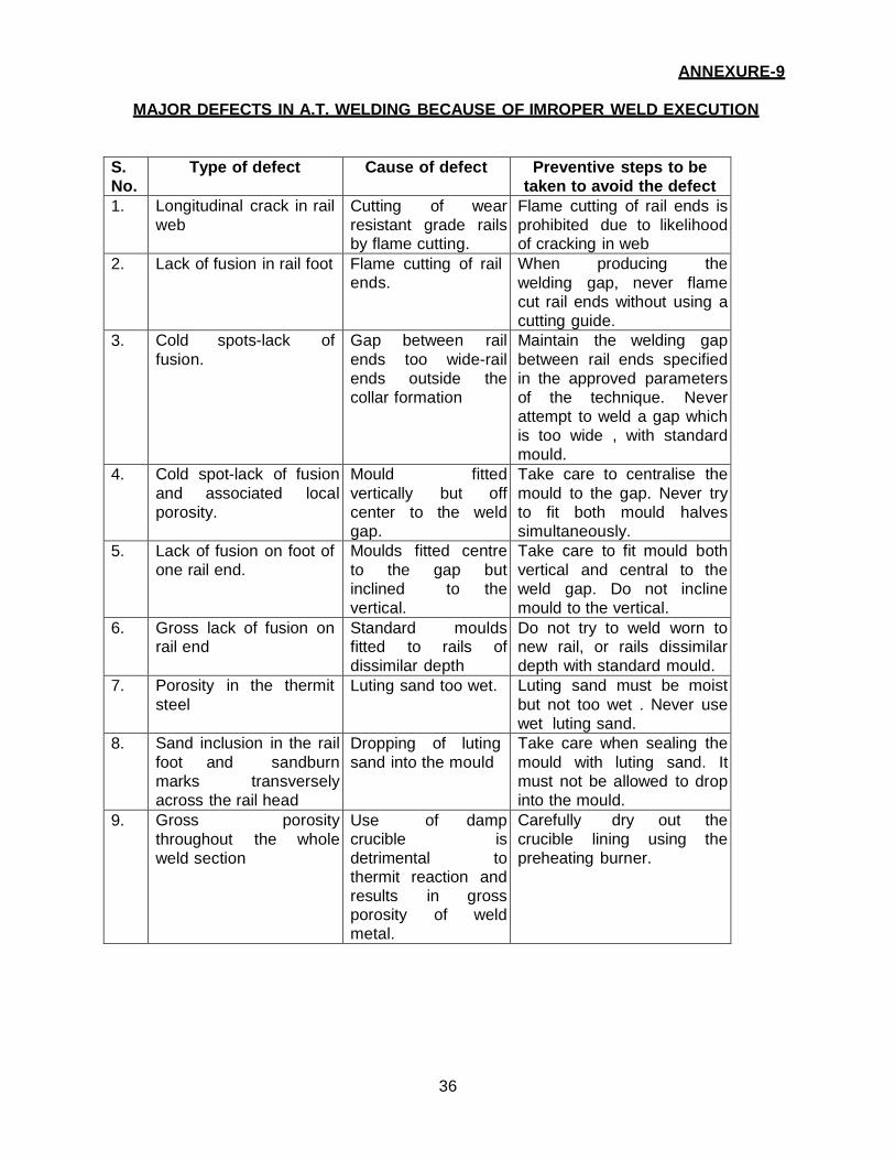
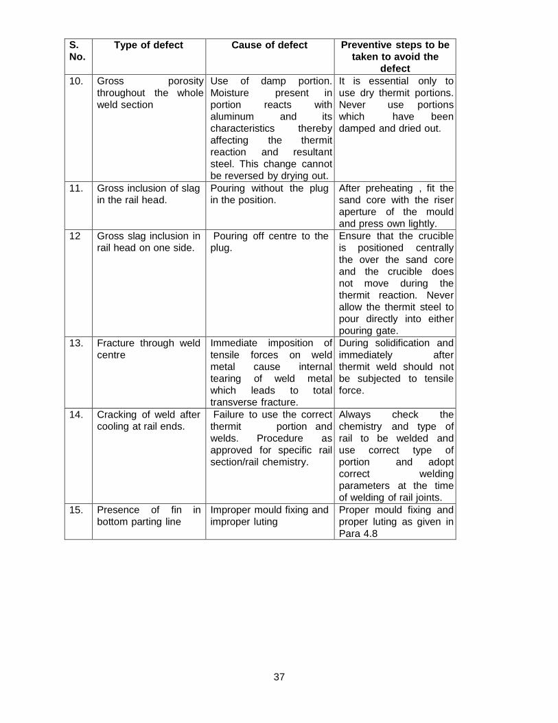
10. Defects in A.T. welding:
The major types of defects which can cause weld failure because of improper welds execution are given in Annexure 9.
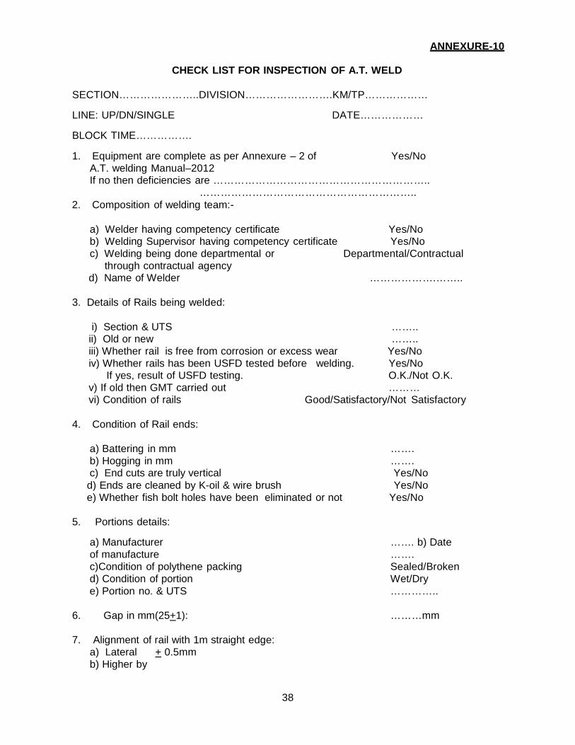
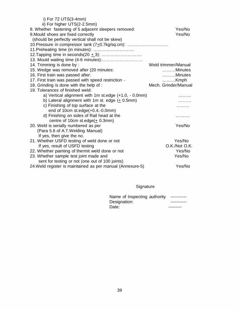
11. Check list for inspection of A.T. welds:
A check list for reference of the officials inspecting A.T. Welds is given in Annexure 10.
20
ANNEXURE-1
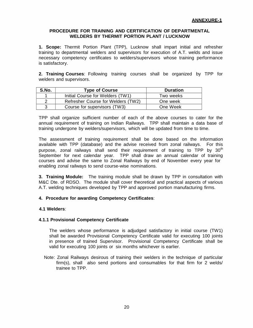
PROCEDURE FOR TRAINING AND CERTIFICATION OF DEPARTMENTAL WELDERS BY THERMIT PORTION PLANT / LUCKNOW
1. Scope: Thermit Portion Plant (TPP), Lucknow shall impart initial and refresher training to departmental welders and supervisors for execution of A.T. welds and issue necessary competency certificates to welders/supervisors whose training performance is satisfactory.
2. Training Courses: Following training courses shall be organized by TPP for welders and supervisors.
S.No. Type of Course Duration
1 Initial Course for Welders (TW1) Two weeks 2 Refresher Course for Welders (TW2) One week 3 Course for supervisors (TW3) One Week
TPP shall organize sufficient number of each of the above courses to cater for the annual requirement of training on Indian Railways. TPP shall maintain a data base of training undergone by welders/supervisors, which will be updated from time to time.
The assessment of training requirement shall be done based on the information available with TPP (database) and the advise received from zonal railways. For this purpose, zonal railways shall send their requirement of training to TPP by 30th
September for next calendar year. TPP shall draw an annual calendar of training courses and advise the same to Zonal Railways by end of November every year for enabling zonal railways to send course-wise nominations.
3. Training Module: The training module shall be drawn by TPP in consultation with M&C Dte. of RDSO. The module shall cover theoretical and practical aspects of various A.T. welding techniques developed by TPP and approved portion manufacturing firms.
4. Procedure for awarding Competency Certificates:
4.1 Welders:
4.1.1 Provisional Competency Certificate
The welders whose performance is adjudged satisfactory in initial course (TW1) shall be awarded Provisional Competency Certificate valid for executing 100 joints in presence of trained Supervisor. Provisional Competency Certificate shall be valid for executing 100 joints or six months whichever is earlier.
Note: Zonal Railways desirous of training their welders in the technique of particular
firm(s), shall also send portions and consumables for that firm for 2 welds/ trainee to TPP.
21
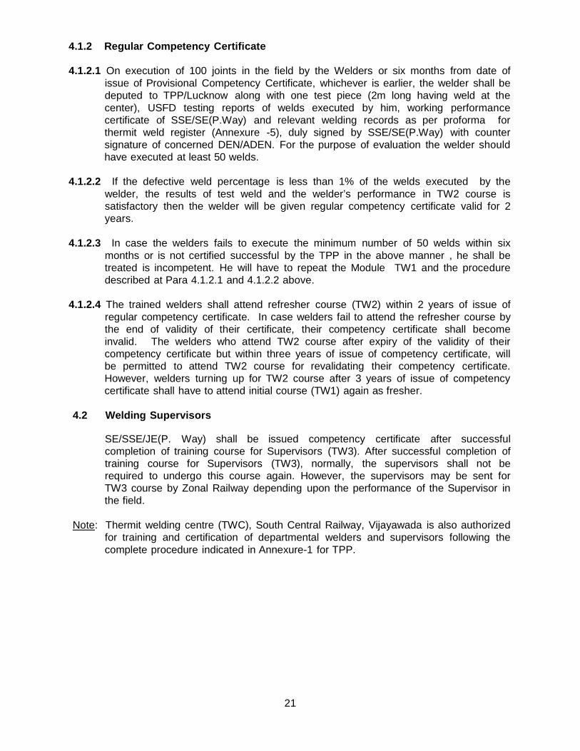
4.1.2 Regular Competency Certificate 4.1.2.1 On execution of 100 joints in the field by the Welders or six months from date of
issue of Provisional Competency Certificate, whichever is earlier, the welder shall be deputed to TPP/Lucknow along with one test piece (2m long having weld at the center), USFD testing reports of welds executed by him, working performance certificate of SSE/SE(P.Way) and relevant welding records as per proforma for thermit weld register (Annexure -5), duly signed by SSE/SE(P.Way) with counter signature of concerned DEN/ADEN. For the purpose of evaluation the welder should have executed at least 50 welds.
4.1.2.2 If the defective weld percentage is less than 1% of the welds executed by the
welder, the results of test weld and the welder’s performance in TW2 course is satisfactory then the welder will be given regular competency certificate valid for 2 years.
4.1.2.3 In case the welders fails to execute the minimum number of 50 welds within six
months or is not certified successful by the TPP in the above manner , he shall be treated is incompetent. He will have to repeat the Module TW1 and the procedure described at Para 4.1.2.1 and 4.1.2.2 above.
4.1.2.4 The trained welders shall attend refresher course (TW2) within 2 years of issue of
regular competency certificate. In case welders fail to attend the refresher course by the end of validity of their certificate, their competency certificate shall become invalid. The welders who attend TW2 course after expiry of the validity of their competency certificate but within three years of issue of competency certificate, will be permitted to attend TW2 course for revalidating their competency certificate. However, welders turning up for TW2 course after 3 years of issue of competency certificate shall have to attend initial course (TW1) again as fresher.
4.2 Welding Supervisors
SE/SSE/JE(P. Way) shall be issued competency certificate after successful completion of training course for Supervisors (TW3). After successful completion of training course for Supervisors (TW3), normally, the supervisors shall not be required to undergo this course again. However, the supervisors may be sent for TW3 course by Zonal Railway depending upon the performance of the Supervisor in the field.
Note: Thermit welding centre (TWC), South Central Railway, Vijayawada is also authorized
for training and certification of departmental welders and supervisors following the complete procedure indicated in Annexure-1 for TPP.
22
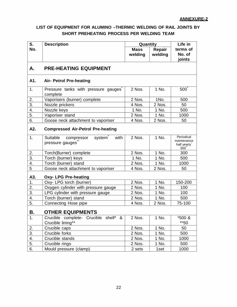
ANNEXURE-2
LIST OF EQUIPMENT FOR ALUMINO –THERMIC WELDING OF RAIL JOINTS BY SHORT PREHEATING PROCESS PER WELDING TEAM
S. No.
Description Quantity Life in terms of
No. of joints
Mass welding
Repair welding
A. PRE-HEATING EQUIPMENT A1. Air- Petrol Pre-heating
1. Pressure tanks with pressure gauges*
complete 2 Nos. 1 No. 500*
2. Vaporisers (burner) complete 2 Nos. 1No. 500 3. Nozzle prickers 4 Nos. 2 Nos. 50 4. Nozzle keys 1 No. 1 No. 500 5. Vaporiser stand 2 Nos. 1 No. 1000 6. Goose neck attachment to vaporiser 4 Nos. 2 Nos. 50
A2. Compressed Air-Petrol Pre-heating
1. Suitable compressor system* with pressure gauges**
2 Nos. 1 No. Periodical maintenance half yearly*
500**
2. Torch(Burner) complete 2 Nos. 1 No. 300 3. Torch (burner) keys 1 No. 1 No. 500 4. Torch (burner) stand 2 Nos. 1 No. 1000 5 Goose neck attachment to vaporiser 4 Nos. 2 Nos. 50
A3. Oxy- LPG Pre-heating 1. Oxy- LPG torch (burner) 2 Nos. 1 No. 150-200 2. Oxygen cylinder with pressure gauge 2 Nos. 1 No. 100 3. LPG cylinder with pressure gauge 2 Nos. 1 No. 100 4. Torch (burner) stand 2 Nos. 1 No. 500 5. Connecting Hose pipe 4 Nos. 2 Nos. 75-100
B. OTHER EQUIPMENTS 1. Crucible complete- Crucible shell* &
Crucible lining** 2 Nos. 1 No. *500 &
**50 2. Crucible caps 2 Nos. 1 No. 50 3. Crucible forks 2 Nos. 1 No. 500 4. Crucible stands 2 Nos. 1 No. 1000 5. Crucible rings 2 Nos. 1 No. 500 6. Mould pressure (clamp) 2 sets 1set 1000
23
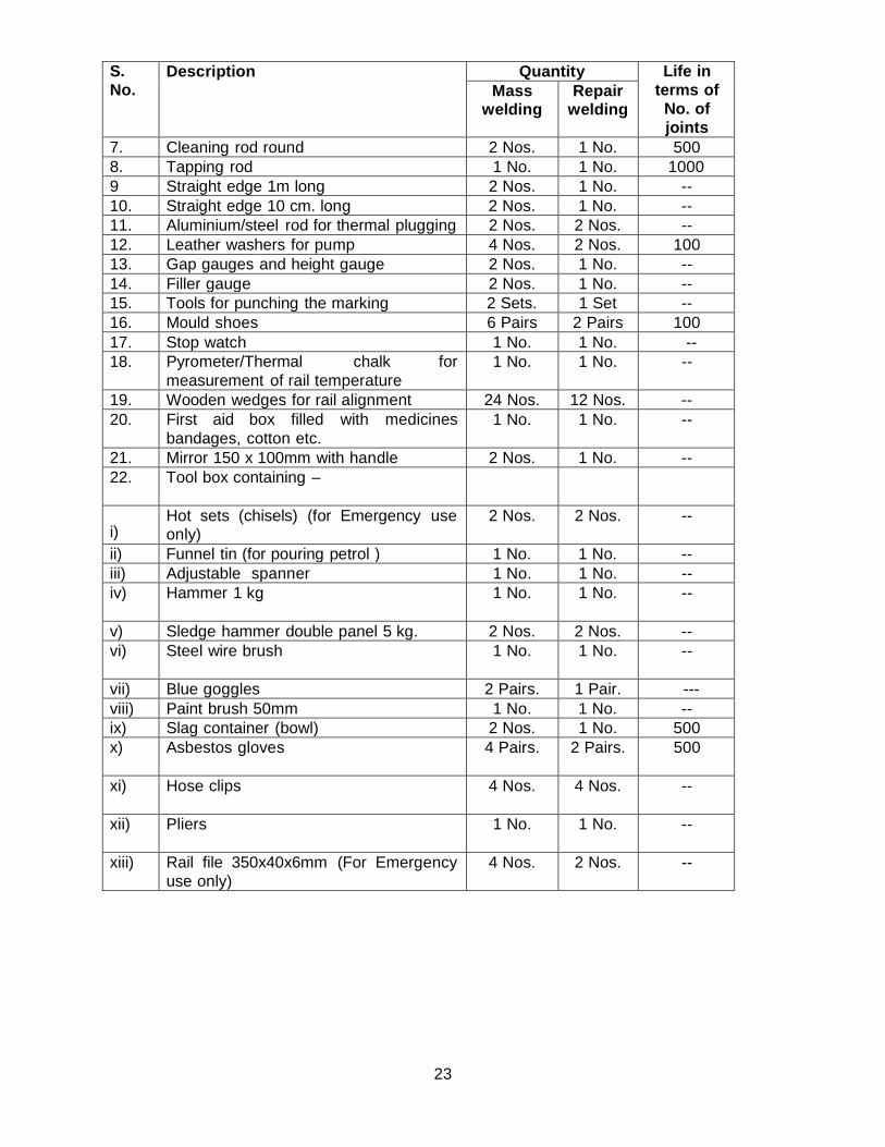
S. No.
Description Quantity Life in terms of
No. of joints
Mass welding
Repair welding
7. Cleaning rod round 2 Nos. 1 No. 500 8. Tapping rod 1 No. 1 No. 1000 9 Straight edge 1m long 2 Nos. 1 No. -- 10. Straight edge 10 cm. long 2 Nos. 1 No. -- 11. Aluminium/steel rod for thermal plugging 2 Nos. 2 Nos. -- 12. Leather washers for pump 4 Nos. 2 Nos. 100 13. Gap gauges and height gauge 2 Nos. 1 No. -- 14. Filler gauge 2 Nos. 1 No. -- 15. Tools for punching the marking 2 Sets. 1 Set -- 16. Mould shoes 6 Pairs 2 Pairs 100 17. Stop watch 1 No. 1 No. -- 18. Pyrometer/Thermal chalk for
measurement of rail temperature 1 No. 1 No. --
19. Wooden wedges for rail alignment 24 Nos. 12 Nos. -- 20. First aid box filled with medicines
bandages, cotton etc. 1 No. 1 No. --
21. Mirror 150 x 100mm with handle 2 Nos. 1 No. -- 22. Tool box containing –
i)
Hot sets (chisels) (for Emergency use only)
2 Nos. 2 Nos. --
ii) Funnel tin (for pouring petrol ) 1 No. 1 No. -- iii) Adjustable spanner 1 No. 1 No. -- iv) Hammer 1 kg 1 No. 1 No. --
v) Sledge hammer double panel 5 kg. 2 Nos. 2 Nos. -- vi) Steel wire brush 1 No. 1 No. --
vii) Blue goggles 2 Pairs. 1 Pair. --- viii) Paint brush 50mm 1 No. 1 No. -- ix) Slag container (bowl) 2 Nos. 1 No. 500 x) Asbestos gloves 4 Pairs. 2 Pairs. 500
xi) Hose clips 4 Nos. 4 Nos. --
xii) Pliers 1 No. 1 No. --
xiii) Rail file 350x40x6mm (For Emergency use only)
4 Nos. 2 Nos. --
24
S. No.
Description Quantity Life in terms of
No. of joints
Mass welding
Repair welding
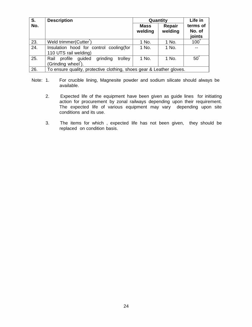
23. Weld trimmer(Cutter*) 1 No. 1 No. 100*
24. Insulation hood for control cooling(for 110 UTS rail welding)
1 No. 1 No. --
25. Rail profile guided grinding trolley (Grinding wheel*).
1 No. 1 No. 50*
26. To ensure quality, protective clothing, shoes gear & Leather gloves.
Note: 1. For crucible lining, Magnesite powder and sodium silicate should always be available.
2. Expected life of the equipment have been given as guide lines for initiating
action for procurement by zonal railways depending upon their requirement. The expected life of various equipment may vary depending upon site conditions and its use.
3. The items for which , expected life has not been given, they should be
replaced on condition basis.
25
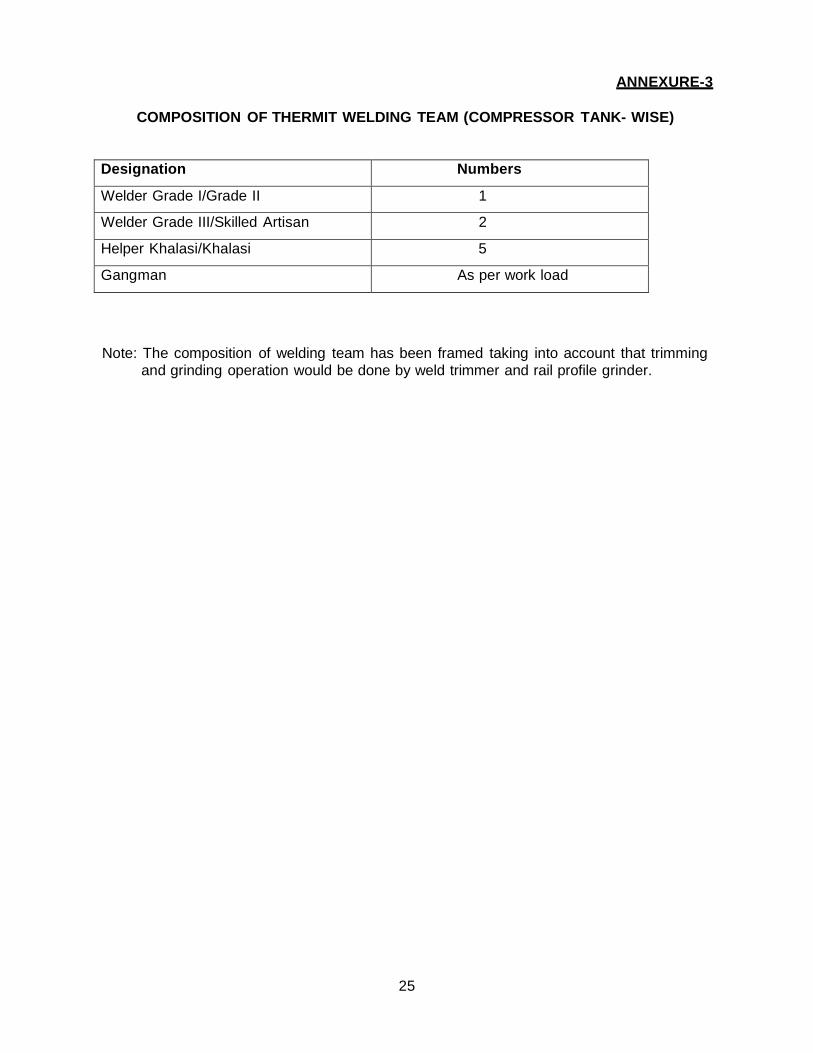
ANNEXURE-3
COMPOSITION OF THERMIT WELDING TEAM (COMPRESSOR TANK- WISE)
Designation Numbers
Welder Grade I/Grade II 1
Welder Grade III/Skilled Artisan 2
Helper Khalasi/Khalasi 5
Gangman As per work load
Note: The composition of welding team has been framed taking into account that trimming and grinding operation would be done by weld trimmer and rail profile grinder.
26
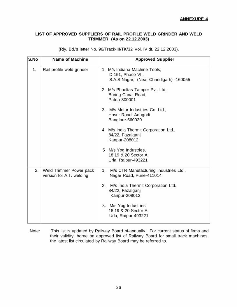
ANNEXURE 4
LIST OF APPROVED SUPPLIERS OF RAIL PROFILE WELD GRINDER AND WELD TRIMMER (As on 22.12.2003)
(Rly. Bd.’s letter No. 96/Track-III/TK/32 Vol. IV dt. 22.12.2003).
S.No Name of Machine Approved Supplier
1. Rail profile weld grinder 1. M/s Indiana Machine Tools, D-151, Phase-VII, S.A.S Nagar, (Near Chandigarh) -160055
2. M/s Phooltas Tamper Pvt. Ltd.,
Boring Canal Road, Patna-800001
3. M/s Motor Industries Co. Ltd.,
Hosur Road, Adugodi Banglore-560030
4 M/s India Thermit Corporation Ltd.,
84/22, Fazalganj Kanpur-208012
5 M/s Yog Industries,
18,19 & 20 Sector A, Urla, Raipur-493221
2. Weld Trimmer Power pack version for A.T. welding
1. M/s CTR Manufacturing Industries Ltd., Nagar Road, Pune-411014
2. M/s India Thermit Corporation Ltd.,
84/22, Fazalganj Kanpur-208012
3. M/s Yog Industries,
18,19 & 20 Sector A, Urla, Raipur-493221
Note: This list is updated by Railway Board bi-annually. For current status of firms and
their validity, borne on approved list of Railway Board for small track machines, the latest list circulated by Railway Board may be referred to.
27
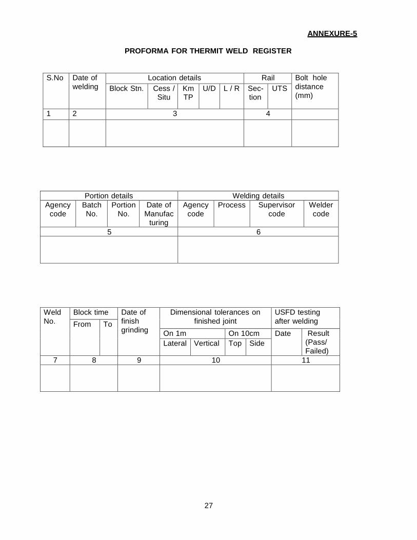
ANNEXURE-5
PROFORMA FOR THERMIT WELD REGISTER
S.No Date of welding
Location details Rail Bolt hole distance (mm)
Block Stn. Cess / Situ
Km TP
U/D L / R Sec- tion
UTS
1 2 3 4
Portion details Welding details Agency
code Batch No.
Portion No.
Date of Manufac
turing
Agency code
Process Supervisor code
Welder code
5 6
Weld No.
Block time Date of finish grinding
Dimensional tolerances on finished joint
USFD testing after welding From To
On 1m On 10cm Date Result (Pass/ Failed)
Lateral Vertical Top Side
7 8 9 10 11
28
In service failure details
Test joint date removed
Replacement Weld Reference
Sign. of PWI Welding
Date of sending test joint with reference
Weld1 Weld 2 Failure
S. No. Date S. No.
Date Date Type
12 13 14 15 16
Test joint results
Cha
inag
e of
wel
d
Ref
eren
ce p
oint
for
chai
nage
Date of receipt of results with referen ce
Hardness (BHN) Transverse load
Poro
sity
(%
)
Date of marking ‘X’ for extended guarantee
Rem
arks
Rail Weld HAZ Load Deflection (mm) 17 18 19
29
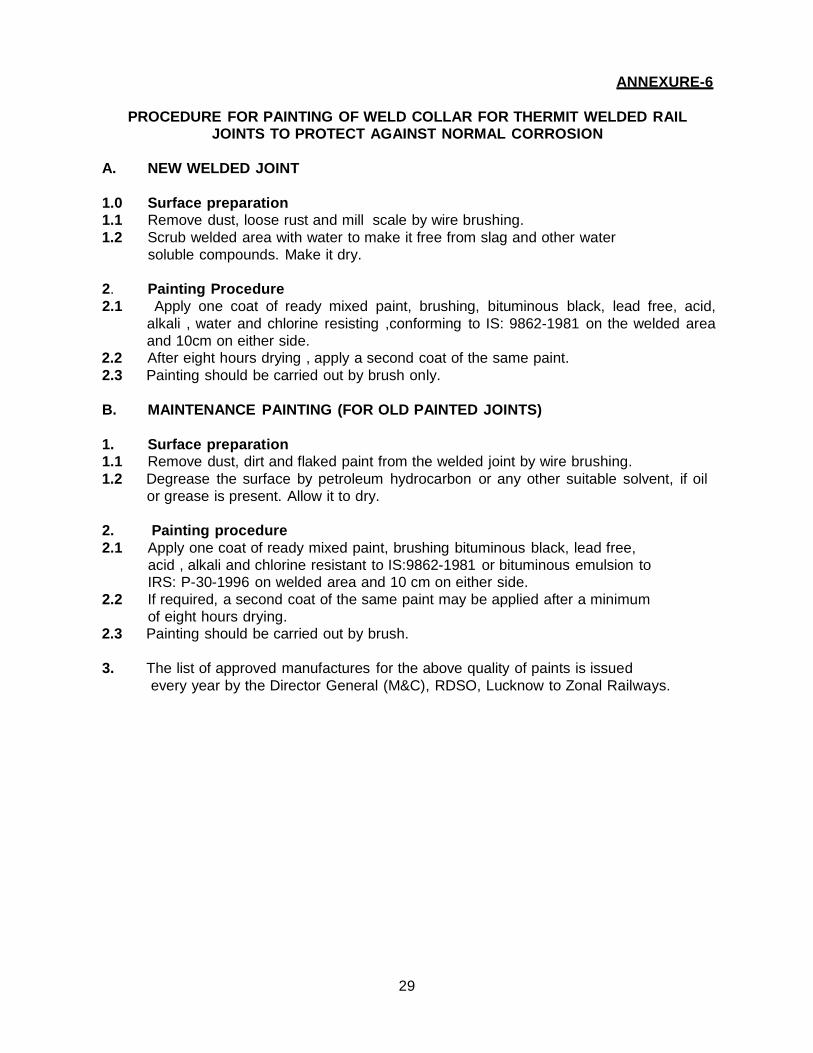
ANNEXURE-6
PROCEDURE FOR PAINTING OF WELD COLLAR FOR THERMIT WELDED RAIL JOINTS TO PROTECT AGAINST NORMAL CORROSION
A. NEW WELDED JOINT
1.0 Surface preparation 1.1 Remove dust, loose rust and mill scale by wire brushing. 1.2 Scrub welded area with water to make it free from slag and other water
soluble compounds. Make it dry. 2. Painting Procedure 2.1 Apply one coat of ready mixed paint, brushing, bituminous black, lead free, acid,
alkali , water and chlorine resisting ,conforming to IS: 9862-1981 on the welded area and 10cm on either side.
2.2 After eight hours drying , apply a second coat of the same paint. 2.3 Painting should be carried out by brush only.
B. MAINTENANCE PAINTING (FOR OLD PAINTED JOINTS)
1. Surface preparation 1.1 Remove dust, dirt and flaked paint from the welded joint by wire brushing. 1.2 Degrease the surface by petroleum hydrocarbon or any other suitable solvent, if oil
or grease is present. Allow it to dry. 2. Painting procedure 2.1 Apply one coat of ready mixed paint, brushing bituminous black, lead free,
acid , alkali and chlorine resistant to IS:9862-1981 or bituminous emulsion to IRS: P-30-1996 on welded area and 10 cm on either side.
2.2 If required, a second coat of the same paint may be applied after a minimum of eight hours drying.
2.3 Painting should be carried out by brush. 3. The list of approved manufactures for the above quality of paints is issued
every year by the Director General (M&C), RDSO, Lucknow to Zonal Railways.
30
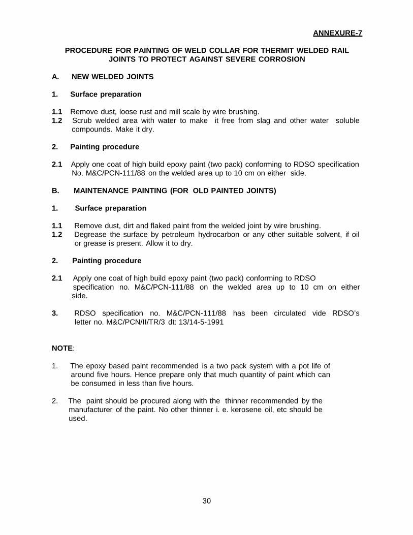
ANNEXURE-7
PROCEDURE FOR PAINTING OF WELD COLLAR FOR THERMIT WELDED RAIL JOINTS TO PROTECT AGAINST SEVERE CORROSION
A. NEW WELDED JOINTS
1. Surface preparation
1.1 Remove dust, loose rust and mill scale by wire brushing. 1.2 Scrub welded area with water to make it free from slag and other water soluble
compounds. Make it dry. 2. Painting procedure
2.1 Apply one coat of high build epoxy paint (two pack) conforming to RDSO specification
No. M&C/PCN-111/88 on the welded area up to 10 cm on either side. B. MAINTENANCE PAINTING (FOR OLD PAINTED JOINTS)
1. Surface preparation
1.1 Remove dust, dirt and flaked paint from the welded joint by wire brushing. 1.2 Degrease the surface by petroleum hydrocarbon or any other suitable solvent, if oil
or grease is present. Allow it to dry. 2. Painting procedure
2.1 Apply one coat of high build epoxy paint (two pack) conforming to RDSO
specification no. M&C/PCN-111/88 on the welded area up to 10 cm on either side.
3. RDSO specification no. M&C/PCN-111/88 has been circulated vide RDSO’s
letter no. M&C/PCN/II/TR/3 dt: 13/14-5-1991
NOTE:
1. The epoxy based paint recommended is a two pack system with a pot life of
around five hours. Hence prepare only that much quantity of paint which can be consumed in less than five hours.
2. The paint should be procured along with the thinner recommended by the
manufacturer of the paint. No other thinner i. e. kerosene oil, etc should be used.
31
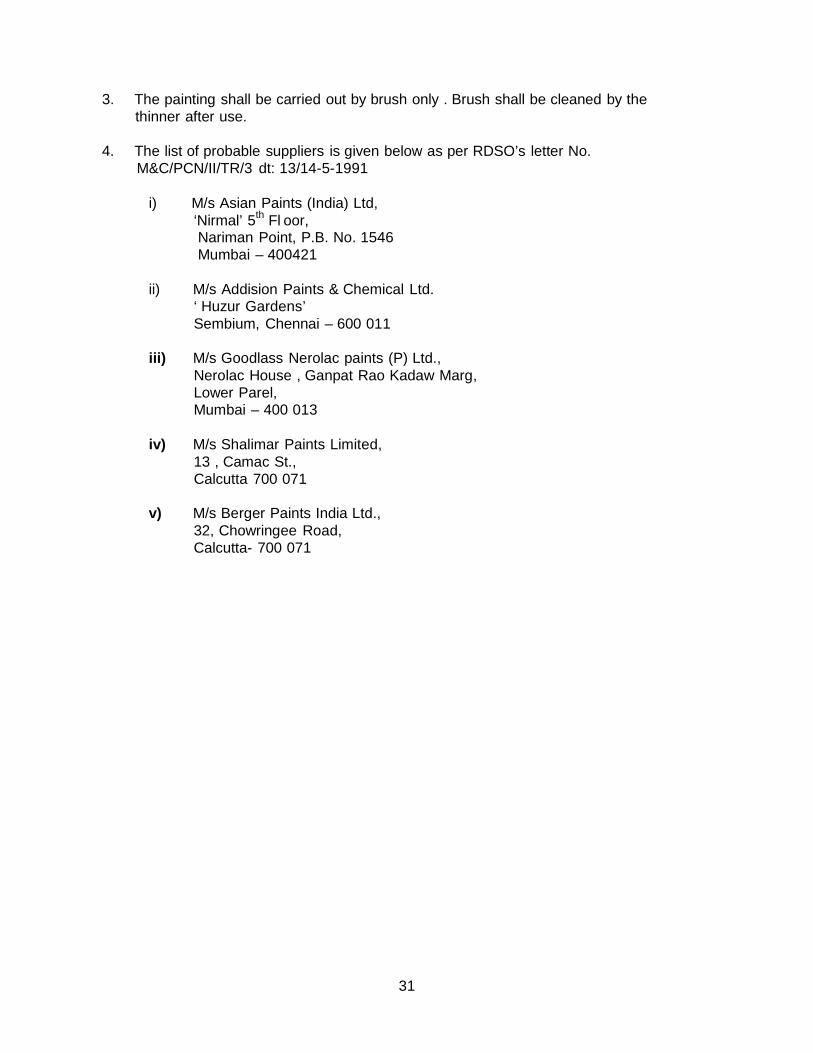
3. The painting shall be carried out by brush only . Brush shall be cleaned by the thinner after use.
4. The list of probable suppliers is given below as per RDSO’s letter No.
M&C/PCN/II/TR/3 dt: 13/14-5-1991
i) M/s Asian Paints (India) Ltd, ‘Nirmal’ 5th Fl oor, Nariman Point, P.B. No. 1546 Mumbai – 400421
ii) M/s Addision Paints & Chemical Ltd.
‘ Huzur Gardens’ Sembium, Chennai – 600 011
iii) M/s Goodlass Nerolac paints (P) Ltd.,
Nerolac House , Ganpat Rao Kadaw Marg, Lower Parel, Mumbai – 400 013
iv) M/s Shalimar Paints Limited,
13 , Camac St., Calcutta 700 071
v) M/s Berger Paints India Ltd.,
32, Chowringee Road, Calcutta- 700 071
32
ANNEXURE- 8
EXTRACTS FROM IRST-19-2012 CLAUSE 4.2 ON MECHANICAL AND METALLURGICAL TESTS ON TEST WELDS AND RETESTS
4.2 Mechanical and Metallurgical tests on test welds
4.2.1 Two new rail pieces of same section and grade, each approximately 750mm long,
shall be used to make test weld joint. The welded joint shall be made as per the technique
offered by the manufacturer. The rail table and sides of rail head shall be finished to the
geometrical tolerances specified in Clause 18.1 of IRST-19-2012.
4.2.2 Hardness test
Brinell hardness test shall be carried out at the welded zone, heat affected zones and
parent metal of the rails in accordance with IS:1500, “ Method for Brinell Hardness test for
steel”. The test shall be done on the top surface of the head of the test weld with a ball of
10 mm dia and a test load of 3000 kg maintained for 10 secs. The average hardness values of different rail chemistry is given in Table 1A for reference –
Table - 1A
Type of rail 72 UTS rail 90 UTS rail UIC Cr-Mn or Cr-V
alloy steel rail
Head
Hardened rail
Average
Hardness(BHN)
229 265 311 341
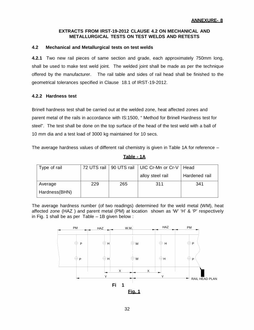
The average hardness number (of two readings) determined for the weld metal (WM), heat affected zone (HAZ ) and parent metal (PM) at location shown as ‘W’ ‘H’ & ‘P’ respectively in Fig. 1 shall be as per Table – 1B given below :
PM HAZ W.M. HAZ PM
P H W H P
P H W H P
X
Y
Fi 1
X
Y Fig. 1
RAIL HEAD PLAN
33
Note:
(i) For 25mm gap SKV welding & for any preheating device used. (Air-petrol/ Compressed Air Petrol/ Oxy-LPG)
X = 40 mm Y = 100 mm
(ii) For 50mm gap combination joint welding & for any preheating device
used.
X = 60 mm Y = 120 mm
(iii) For 75 mm wide gap welding & for any preheating device used
X = 80 mm Y = 150 mm
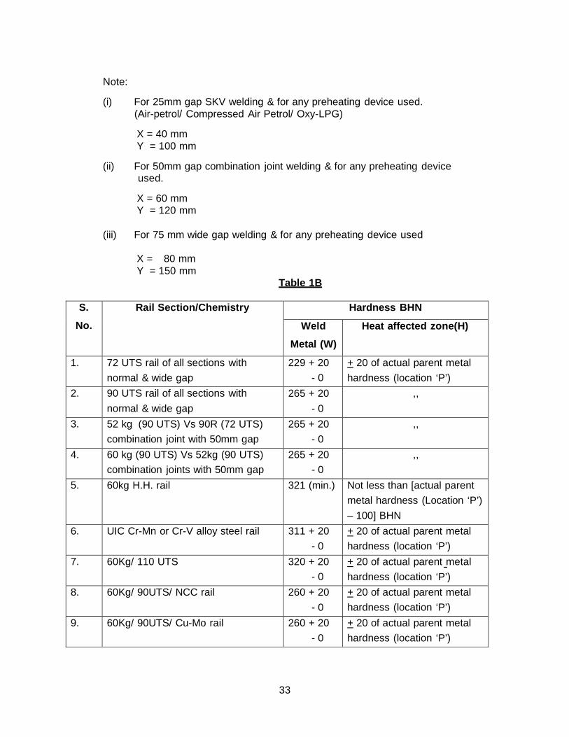
Table 1B
S.
No.
Rail Section/Chemistry Hardness BHN
Weld
Metal (W)
Heat affected zone(H)
1. 72 UTS rail of all sections with normal & wide gap
229 + 20 - 0
+ 20 of actual parent metal hardness (location ‘P’)
2. 90 UTS rail of all sections with normal & wide gap
265 + 20 - 0
,,
3. 52 kg (90 UTS) Vs 90R (72 UTS) combination joint with 50mm gap
265 + 20 - 0
,,
4. 60 kg (90 UTS) Vs 52kg (90 UTS) combination joints with 50mm gap
265 + 20 - 0
,,
5. 60kg H.H. rail 321 (min.) Not less than [actual parent metal hardness (Location ‘P’) – 100] BHN
6. UIC Cr-Mn or Cr-V alloy steel rail 311 + 20 - 0
+ 20 of actual parent metal hardness (location ‘P’)
7. 60Kg/ 110 UTS 320 + 20 - 0
+ 20 of actual parent metal hardness (location ‘P’)
8. 60Kg/ 90UTS/ NCC rail 260 + 20 - 0
+ 20 of actual parent metal hardness (location ‘P’)
9. 60Kg/ 90UTS/ Cu-Mo rail 260 + 20 - 0
+ 20 of actual parent metal hardness (location ‘P’)
34
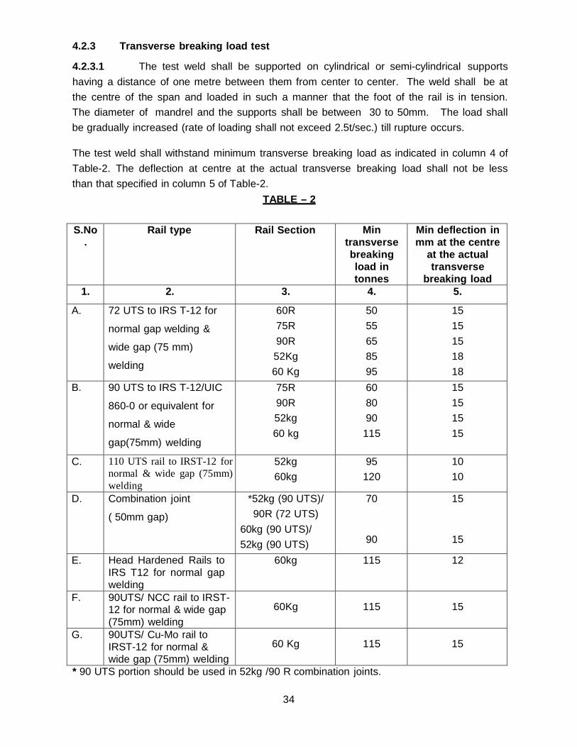
4.2.3 Transverse breaking load test
4.2.3.1 The test weld shall be supported on cylindrical or semi-cylindrical supports having a distance of one metre between them from center to center. The weld shall be at the centre of the span and loaded in such a manner that the foot of the rail is in tension. The diameter of mandrel and the supports shall be between 30 to 50mm. The load shall be gradually increased (rate of loading shall not exceed 2.5t/sec.) till rupture occurs.
The test weld shall withstand minimum transverse breaking load as indicated in column 4 of Table-2. The deflection at centre at the actual transverse breaking load shall not be less than that specified in column 5 of Table-2.
TABLE – 2
S.No .
Rail type Rail Section Min transverse breaking load in tonnes
Min deflection in mm at the centre
at the actual transverse
breaking load 1. 2. 3. 4. 5.
A. 72 UTS to IRS T-12 for
normal gap welding &
wide gap (75 mm)
welding
60R 75R 90R 52Kg 60 Kg
50 55 65 85 95
15 15 15 18 18
B. 90 UTS to IRS T-12/UIC
860-0 or equivalent for
normal & wide
gap(75mm) welding
75R 90R 52kg 60 kg
60 80 90
115
15 15 15 15
C. 110 UTS rail to IRST-12 for normal & wide gap (75mm) welding
52kg 60kg
95 120
10 10
D. Combination joint
( 50mm gap)
*52kg (90 UTS)/ 90R (72 UTS)
60kg (90 UTS)/ 52kg (90 UTS)
70
90
15
15
E. Head Hardened Rails to IRS T12 for normal gap welding
60kg 115 12
F. 90UTS/ NCC rail to IRST- 12 for normal & wide gap (75mm) welding
60Kg
115
15
G. 90UTS/ Cu-Mo rail to IRST-12 for normal & wide gap (75mm) welding
60 Kg
115
15
* 90 UTS portion should be used in 52kg /90 R combination joints.
35
4.2.3.2 If the fracture does not occur through weld, a slice shall be cut transversely at
the weld and etched in boiling 1:1 Hydrochloric acid for about 20 minutes to determine
casting defects if any. 4.2.3.3 The fractured surface of the weld, or in case where macro - etching is done on transverse section through the joint, shall not show defects such as blow holes, porosity and inclusions etc. having individual size greater than 2mm dia. There shall not be more than three defects of size < 2mm dia. The distance between two defects of size < 2mm dia. shall not be less than 20mm. The macro - etched transverse section shall not show cracks of length 2mm or greater. The defects should not be interconnected and none of these shall extend upto the outer surface of the weld. There shall not be any lack of fusion and clustered porosities. The fractured surface shall also not show the presence of accretions or mirror like surface and shall be crystalline in appearance.
For A.T. welds of 110UTS rails, 90UTS/NCC rails, 90UTS/Cu-Mo rails, fractured surface or in case where macro etching is done on transverse section through the joint, shall not show defects such as blow holes, porosity and inclusions etc.
4.3 Retests
4.3.1 If the results of any of the tests referred to in clause 4.1 and 4.2 are found to be unsatisfactory, the batch will stand rejected. However, retests can be carried out at the manufacturer’s request. These retests shall be carried out as per para 4.1 and 4.2 on twice the original sample size.
4.3.2 If the results of all the retest samples are satisfactory, the batch represented by the sample portions shall be accepted. If any sample fails to meet the requirements of any of the tests, the batch shall be rejected.
36
ANNEXURE-9
MAJOR DEFECTS IN A.T. WELDING BECAUSE OF IMROPER WELD EXECUTION
S. No.
Type of defect Cause of defect Preventive steps to be taken to avoid the defect
1. Longitudinal crack in rail web
Cutting of wear resistant grade rails by flame cutting.
Flame cutting of rail ends is prohibited due to likelihood of cracking in web
2. Lack of fusion in rail foot Flame cutting of rail ends.
When producing the welding gap, never flame cut rail ends without using a cutting guide.
3. Cold spots-lack of fusion.
Gap between rail ends too wide-rail ends outside the collar formation
Maintain the welding gap between rail ends specified in the approved parameters of the technique. Never attempt to weld a gap which is too wide , with standard mould.
4. Cold spot-lack of fusion and associated local porosity.
Mould fitted vertically but off center to the weld gap.
Take care to centralise the mould to the gap. Never try to fit both mould halves simultaneously.
5. Lack of fusion on foot of one rail end.
Moulds fitted centre to the gap but inclined to the vertical.
Take care to fit mould both vertical and central to the weld gap. Do not incline mould to the vertical.
6. Gross lack of fusion on rail end
Standard moulds fitted to rails of dissimilar depth
Do not try to weld worn to new rail, or rails dissimilar depth with standard mould.
7. Porosity in the thermit steel
Luting sand too wet. Luting sand must be moist but not too wet . Never use wet luting sand.
8. Sand inclusion in the rail foot and sandburn marks transversely across the rail head
Dropping of luting sand into the mould
Take care when sealing the mould with luting sand. It must not be allowed to drop into the mould.
9. Gross porosity throughout the whole weld section
Use of damp crucible is detrimental to thermit reaction and results in gross porosity of weld metal.
Carefully dry out the crucible lining using the preheating burner.
37
S. No.
Type of defect Cause of defect Preventive steps to be taken to avoid the
defect 10. Gross porosity
throughout the whole weld section
Use of damp portion. Moisture present in portion reacts with aluminum and its characteristics thereby affecting the thermit reaction and resultant steel. This change cannot be reversed by drying out.
It is essential only to use dry thermit portions. Never use portions which have been damped and dried out.
11. Gross inclusion of slag in the rail head.
Pouring without the plug in the position.
After preheating , fit the sand core with the riser aperture of the mould and press own lightly.
12 Gross slag inclusion in rail head on one side.
Pouring off centre to the plug.
Ensure that the crucible is positioned centrally the over the sand core and the crucible does not move during the thermit reaction. Never allow the thermit steel to pour directly into either pouring gate.
13. Fracture through weld centre
Immediate imposition of tensile forces on weld metal cause internal tearing of weld metal which leads to total transverse fracture.
During solidification and immediately after thermit weld should not be subjected to tensile force.
14. Cracking of weld after cooling at rail ends.
Failure to use the correct thermit portion and welds. Procedure as approved for specific rail section/rail chemistry.
Always check the chemistry and type of rail to be welded and use correct type of portion and adopt correct welding parameters at the time of welding of rail joints.
15. Presence of fin in bottom parting line
Improper mould fixing and improper luting
Proper mould fixing and proper luting as given in Para 4.8
38
ANNEXURE-10
CHECK LIST FOR INSPECTION OF A.T. WELD SECTION…………………..DIVISION…………………….KM/TP………………
LINE: UP/DN/SINGLE DATE………………
BLOCK TIME…………….
1. Equipment are complete as per Annexure – 2 of Yes/No A.T. welding Manual–2012 If no then deficiencies are ……………………………………………………..
…………………………………………………….. 2. Composition of welding team:-
a) Welder having competency certificate Yes/No b) Welding Supervisor having competency certificate Yes/No c) Welding being done departmental or Departmental/Contractual
through contractual agency d) Name of Welder ……………….……..
3. Details of Rails being welded:
i) Section & UTS ……..
ii) Old or new …….. iii) Whether rail is free from corrosion or excess wear Yes/No iv) Whether rails has been USFD tested before welding. Yes/No
If yes, result of USFD testing. O.K./Not O.K. v) If old then GMT carried out ……… vi) Condition of rails Good/Satisfactory/Not Satisfactory
4. Condition of Rail ends:
a) Battering in mm ……. b) Hogging in mm ……. c) End cuts are truly vertical Yes/No d) Ends are cleaned by K-oil & wire brush Yes/No e) Whether fish bolt holes have been eliminated or not Yes/No
5. Portions details:
a) Manufacturer ……. b) Date of manufacture ……. c)Condition of polythene packing Sealed/Broken d) Condition of portion Wet/Dry e) Portion no. & UTS …………..
6. Gap in mm(25+1): ………mm
7. Alignment of rail with 1m straight edge:
a) Lateral + 0.5mm b) Higher by
39
i) For 72 UTS(3-4mm) ii) For higher UTS(2-2.5mm)
8. Whether fastening of 5 adjacent sleepers removed: Yes/No 9.Mould shoes are fixed correctly Yes/No
(should be perfectly vertical shall not be skew) 10.Pressure in compressor tank (7+0.7kg/sq.cm): ………………………. 11.Preheating time (in minutes): ………………………. 12.Tapping time in seconds(20 + 3): ………………………. 13. Mould waiting time (4-6 minutes):………………………. 14. Trimming is done by : Weld trimmer/Manual 15. Wedge was removed after (20 minutes: ………Minutes 16. First train was passed after: ………Minutes 17. First train was passed with speed restriction - ………Kmph 18. Grinding is done with the help of : Mech. Grinder/Manual 19. Tolerances of finished weld:
a) Vertical alignment with 1m st.edge (+1.0, - 0.0mm) ……… b) Lateral alignment with 1m st. edge (+ 0.5mm) ……… c) Finishing of top surface at the ………
end of 10cm st.edge(+0.4,-0.0mm) d) Finishing on sides of Rail head at the ……….
centre of 10cm st.edge(+ 0.3mm) 20. Weld is serially numbered as per Yes/No
(Para 5.6 of A.T.Welding Manual) If yes, then give the no.
21. Whether USFD testing of weld done or not Yes/No If yes, result of USFD testing O.K./Not O.K.
22. Whether painting of thermit weld done or not Yes/No 23. Whether sample test joint made and Yes/No
sent for testing or not (one out of 100 joints) 24.Weld register is maintained as per manual (Annexure-5) Yes/No
Signature
Name of Inspecting authority ----------- Designation: ----------- Date: ---------
40
ANNEXURE-11
General guidelines for storage and transportation of A.T. Portion These guidelines represent “Best Practice” with respect to storage of materials.
Stores should be dry, well ventilated, and where required light, power and running water should be available. In all cases building construction should be in compliance with the FIRE regulations applicable to the substances being stored. Consideration shall also be given to the relevant regulations issued in this respect.
The appropriate notices should be displayed where material such as Thermit Portions and Igniters are stored.
Storage of Thermit Portions
Portions should be stored in a secure, non-combustible building. While it is preferable that they should be stored separately, they may be stored with other non inflammable materials, such as equipment and small tools , mould, luting sand in sealed bags, etc. in which case ideally they should be segregated. The store should be dry with ventilation to prevent excess humidity or dampness, and should be designated as a non-smoking area, with no naked flames.
Portions must not be stored in the same building as explosive or flammable items (e.g. Fuel, fuel gases, igniters).
The sealed boxes must not be opened until immediately prior to use. Any spillages should be immediately swept up and the material disposed in accordance with safety data sheets. Steel shovels should not be used on concrete floors, which might create a spark.
Portions should be used in rotation i.e. first in-first out.
Proper notices should be displayed inside and outside the building together with the standard warning sign, which should read “Metallic Powder: In case of fire DO NOT USE WATER”.
The Local Fire Brigade should be informed of exact location of store and nature of contents. Only dry powder extinguishers of appropriate class should be used in the proximity of Thermit powders.
Storage of Igniters
Tubes of igniters should be stored in a locked steel cupboard, or other secure steel container. On no account must these be stored in the same building as the portions.
Transportation of A.T. Portion
A.T. Portion should not be transported in passenger coaches. The package containing igniters should be kept in tin cases/steel containers.
Manufacturer of portion shall provide a sheet containing best safety practices with every package for guidance of the user covering various aspects in safe handling, storage, transportation and disposal of thermit materials.
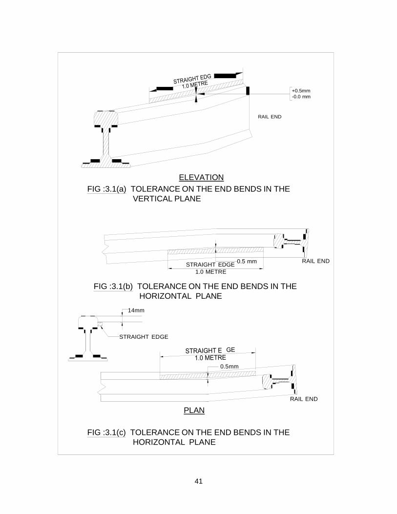
41
+0.5mm -0.0 mm
RAIL END
ELEVATION FIG :3.1(a) TOLERANCE ON THE END BENDS IN THE
VERTICAL PLANE
STRAIGHT EDGE 0.5 mm RAIL END 1.0 METRE
FIG :3.1(b) TOLERANCE ON THE END BENDS IN THE
HORIZONTAL PLANE
14mm
STRAIGHT EDGE
0.5mm
PLAN RAIL END
FIG :3.1(c) TOLERANCE ON THE END BENDS IN THE HORIZONTAL PLANE
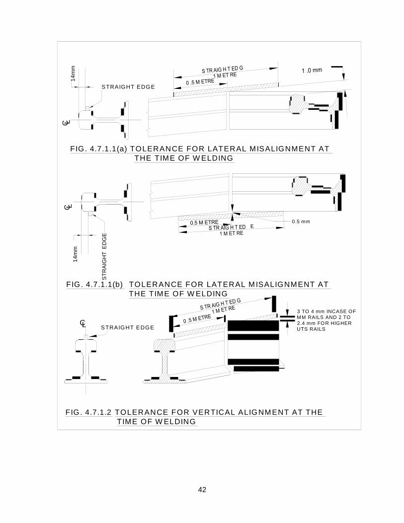
42
C L
C L
14m
m
14m
m
STR
AIG
HT
ED
GE
L
S T R A IG H T E D G E
F IG . 4.7 .1.1 (a) T O L E R A N C E F O R L A T E R A L M IS A L IG N M E N T A T THE TIM E O F W E L D IN G
0.5 m m
F IG . 4.7 .1.1(b) T O L E R A N C E F O R L A T E R A L M IS A L IG N M E N T A T T H E T IM E O F W E L D IN G
C S T R A IG H T E D G E
3 T O 4 m m IN C A S E O F M M R A IL S AN D 2 TO 2.4 m m FO R H IG H E R UT S RA ILS
FIG . 4 .7 .1 .2 TO L E R A N C E FO R V E R T IC A L A L IG NM E N T A T T H E T IM E O F W E L D IN G
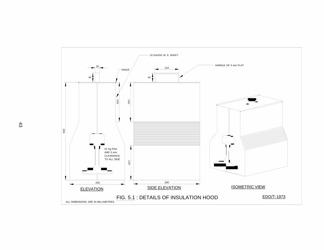
14 0 160
16 0
39 5
43
10 GAUGE M. S. SHEET
20
HINGE
110
HANDLE OF 4 mm FLAT
40 40
52 Kg RAIL AND 3 mm CLEARANCE TO ALL SIDE
250 300
ELEVATION SIDE ELEVATION ISOMETRIC VIEW
ALL DIMENSIONS ARE IN MILLIMETRES.
FIG. 5.1 : DETAILS OF INSULATION HOOD EDO/T-1973
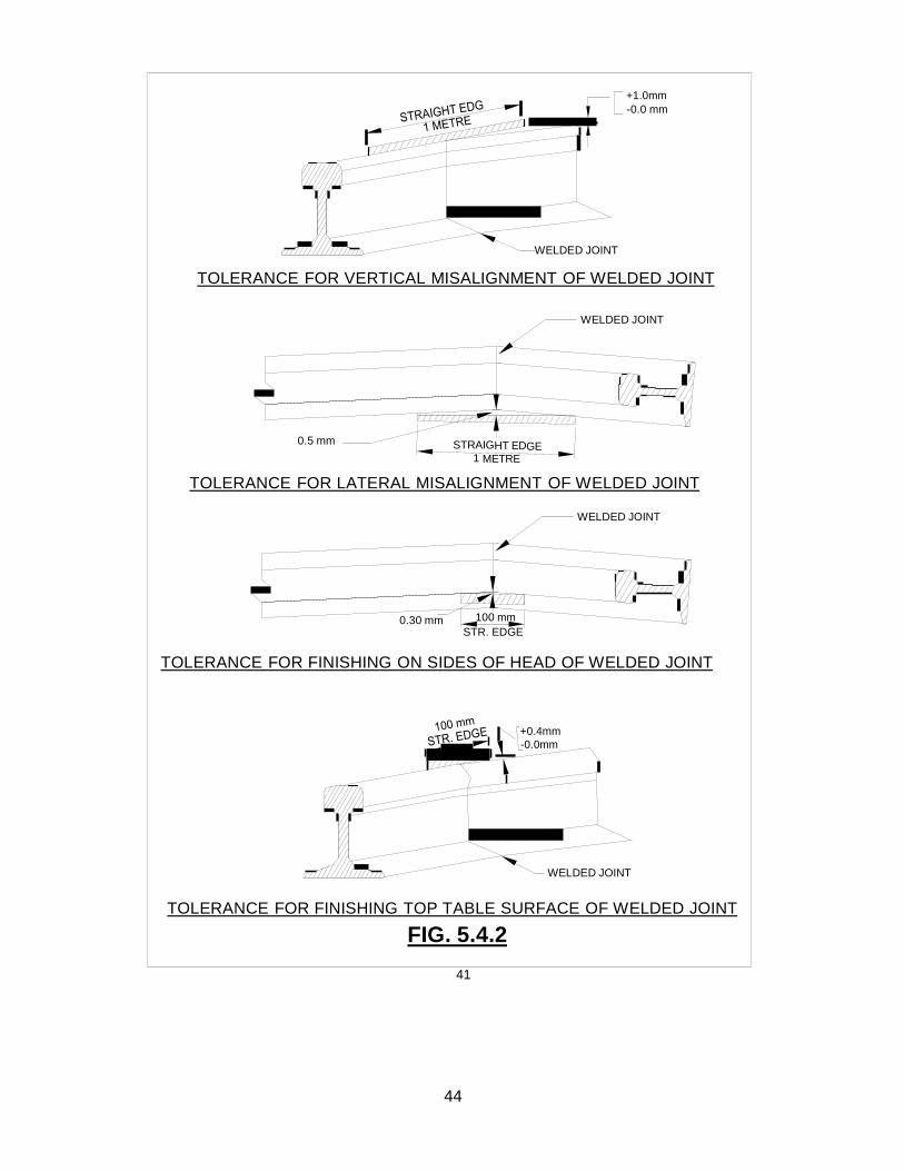
STRAIGHT EDGE 1 METRE
+1.0mm -0.0 mm
WELDED JOINT
TOLERANCE FOR VERTICAL MISALIGNMENT OF WELDED JOINT
WELDED JOINT
0.5 mm
TOLERANCE FOR LATERAL MISALIGNMENT OF WELDED JOINT
WELDED JOINT
0.30 mm 100 mm STR. EDGE
TOLERANCE FOR FINISHING ON SIDES OF HEAD OF WELDED JOINT
+0.4mm -0.0mm
WELDED JOINT
TOLERANCE FOR FINISHING TOP TABLE SURFACE OF WELDED JOINT
FIG. 5.4.2
41
44