manual - · pdf fileelectronic error codes ... 7.2 hitachi sj200 ... 7.3.2 checking the last...
TRANSCRIPT

HTC 500MANUAL
GB
Translation of manual in original language


Contact InformationHTC Sweden ABBox 69SE-614 22 Söderköping - SwedenTel: +46 (0) 121-294 00Fax: +46 (0) 121-152 12
You can find addresses for our retailers and service partners on ourwebsite:www.htc-floorsystems.com
Always specify the model and serial number when asking questionsabout your product.
TrademarksHTC is a trademark owned by HTC Sweden AB. Other names andproducts mentioned in this manual may be registered trademarksowned by the relevant companies.
© 2007 HTC Sweden AB. All rights reserved.


EC Declaration of conformityManufacturer: HTC Sweden AB
Box 69SE-614 22 SöderköpingSweden+46 (0)121-29400
Type of equipment: Grinding machineMake: HTCModel: HTC 500Year of manufacture: See machine name plateSerial number: See machine name plate
As the manufacturer, we hereby declare under our soleresponsibility that the above product with serial numbers from2004 onward conforms to the applicable regulations in directivesMD 2006/42/EC, EMC 2004/108/EC and LVD 2006/95/EC. Thefollowing standards have been used as a basis: ISO 5349-1:2001,ISO 5349-2:2001, ISO 20643:2005, ISO 3741.
This product was CE-marked in 1997. The technical documentationis available from the manufacturer.
Original of the EC declaration of conformity (Swedish). Otherlanguages are translations of the original of the EC declaration ofconformity.
Söderköping, 01-01-2010
Peter LundgrenDevelopment Manager,HTC Sweden AB
Kåre KilgrenProduct Manager,HTC Sweden AB

HTC 500 Table of contents
Table of contents
1. Introduction.........................................................11.1 General information...................................................... 11.2 Responsibility................................................................11.3 Manual.......................................................................... 1
1.3.1 Safety instructions – Explanation of symbols....... 11.4 Transportation............................................................... 21.5 On delivery....................................................................21.6 Unpacking the machine................................................31.7 Machine name plate..................................................... 41.8 Handling and storage................................................... 41.9 Vibration and noise.......................................................5
1.9.1 Hand and arm vibrations...................................... 51.9.2 Sound pressure level............................................5
2. Safety...................................................................62.1 General Information...................................................... 62.2 Warnings....................................................................... 62.3 Notes.............................................................................7
3. Machine Description.......................................... 93.1 General machine description........................................93.2 Description of Controls – Control Panel..................... 12
4. Usage.................................................................144.1 General Information.................................................... 144.2 Handle settings........................................................... 164.3 Handling weights........................................................ 164.4 Access to grinding tools............................................. 184.5 Fitting and replacing grinding tools.............................18
4.5.1 Fitting grinding tools........................................... 194.5.2 Changing grinding tools......................................20
4.6 Preparations for dry grinding...................................... 204.7 Preparations for wet grinding..................................... 214.8 Operation.................................................................... 22
4.8.1 Standby...............................................................224.8.2 Emergency stop switch...................................... 224.8.3 Starting the machine.......................................... 22
4.9 Making operation easier............................................. 24

Table of contents HTC 500
5. Maintenance and repairs.................................255.1 General Information.................................................... 255.2 Cleaning......................................................................255.3 Daily............................................................................ 255.4 Every week................................................................. 255.5 Every month (or 100 hours)....................................... 265.6 Repairs........................................................................265.7 Spare parts................................................................. 26
6. Faultfinding.......................................................286.1 General Information.................................................... 28
6.1.1 The machine will not start.................................. 286.1.2 The machine vibrates or wears the toolunevenly.......................................................................286.1.3 The machine is grinding at an angle.................. 286.1.4 The machine stops during operation.................. 286.1.5 The fuses trip frequently.....................................296.1.6 The machine cannot cope..................................29
7. Electronic error codes.....................................307.1 General....................................................................... 307.2 Hitachi SJ200..............................................................30
7.2.1 Resetting the frequency converter......................317.2.2 Checking the last error code.............................. 31
7.3 Omron MX2................................................................ 317.3.1 Resetting the frequency converter......................327.3.2 Checking the last error code.............................. 32
8. Technical Data.................................................. 34
9. Environment..................................................... 37
10. Warranty and CE Marking............................. 3810.1 Warranty ...................................................................3810.2 CE marking...............................................................38

HTC 500 Introduction
1.0 1
1. Introduction
1.1. General informationHTC 500 is a grinder that can be used to grind, strip, clean andpolish concrete, natural stone and terrazzo floors. The machine'sarea of application depends on the choice of tool.
Read the manual carefully so that you are totally familiar withthe machine before you start using it. Contact your local retailerfor further information. For contact information, see ContactInformation at the start of the manual.
1.2. ResponsibilityEven though every effort has been made to make this manual ascomplete and accurate as possible, we bear no responsibility forincorrect or missing information. HTC reserves the right to changedescriptions in this manual without giving prior notice.
This manual is protected by the Copyright Act and no part ofit may be copied or used in any other way without the writtenapproval of HTC.
1.3. ManualIn addition to the general functions, this manual deals with theareas of application and the maintenance of the grinder.
1.3.1. Safety instructions – Explanation of symbolsA number of symbols are used in the manual to highlight the mostimportant sections, see below. In order to avoid both personalinjury and material damage as far as possible, it is extremelyimportant to read and understand the text next to these symbolsparticularly carefully. There are other symbols indicating practicaltips. These are to help you use the machine in the easiest and mosteffective way.
The following symbols are used in the document to indicate wherespecial attention is needed.

Introduction HTC 500
2 1.0
The symbol indicates a Warning! and means that incorrect usecan result in personal injury or material damage to the machine oraccessories. If you see this symbol next to a section of text, youmust be particularly careful when reading through the text and notcarry out any stages of which you are unsure. This is to protectyou and other users and to avoid damaging the machine or otherequipment.
The symbol means Note! and indicates that material damage canoccur if the machine or its accessories are used incorrectly. If yousee this symbol next to a section of text, you must be particularlycareful when reading through the text and not carry out any stagesof which you are unsure. This is to avoid damage to the machine orother equipment.
The symbol indicates a Tip! and indicates that you can get tipsand advice on ways to make operating your machine or associatedequipment easier, and to avoid wear. When you see this symbolyou should read the accompanying text to facilitate your work andincrease the service life of the machine.
1.4. TransportationThe appropriate way to transport the machine is to firmly anchor itto a pallet.
1.5. On deliveryThe following items are included in the delivery. Contact youretailer if anything is missing.
• Grinding machine
• Manual
• Locking key for control cabinet

HTC 500 Introduction
1.0 3
• Hammer EZ system
• Splash guard
1.6. Unpacking the machineWarning!
Read through the safety instructions and the manual carefullybefore use.
• Check carefully to see if the packaging or machinehas been damaged during delivery. If there is any signof damage, contact your retailer and report it. Reportpackaging damage to the transport company as well.
• Check that the delivery matches the order. If there are anydiscrepancies, contact your retailer.
Introduction HTC 500
4 1.0
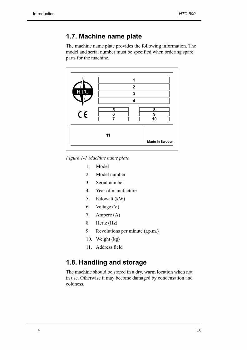
1.7. Machine name plateThe machine name plate provides the following information. Themodel and serial number must be specified when ordering spareparts for the machine.
Figure 1-1 Machine name plate
1. Model2. Model number3. Serial number4. Year of manufacture5. Kilowatt (kW)6. Voltage (V)7. Ampere (A)8. Hertz (Hz)9. Revolutions per minute (r.p.m.)10. Weight (kg)11. Address field
1.8. Handling and storageThe machine should be stored in a dry, warm location when notin use. Otherwise it may become damaged by condensation andcoldness.

HTC 500 Introduction
1.0 5
1.9. Vibration and noiseWarning!
Always use hearing protection when using the machine.
1.9.1. Hand and arm vibrationsHand and arm-weighted vibration level [m/s²] for HTC 500 havebeen measured using equipment approved in accordance withISO 5349-1:2001. Measurement uncertainty for the measurementequipment has been assessed as +/- 2%.
The machine has been tested in accordance with ISO 5349-2:2001and ISO 20643:2005 in order to identify the operations thatcontribute to the most frequent vibration exposures. At vibrationlevels > 2.5 m/s², the exposure time should be limited inaccordance with the table below. For vibration levels > 5 m/s²,immediate measures should be taken by the employer to ensure thatthe exposure time does not exceed the time specified in the tablebelow.
Identified workconditions
Measured values[m/s²]
Daily permittedexposure (number ofhours)
Grinding/polishing 2.76 unlimitedFloor preparation (T-rex) 5.4 5.12
1.9.2. Sound pressure levelThis machine has been tested for noise in accordance with ISO3741. For information on sound pressure levels, see the table inchapter Technical Data on page 34.

Safety HTC 500
6 1.0
2. Safety
2.1. General InformationThis chapter contains all the warnings and notes that have to beconsidered for HTC 500.
2.2. WarningsWarning!
The machine may only be used or repaired by personnel who havereceived the requisite theoretical and practical training and whohave read the user manual.
Warning!
Never use the machine in an environment with a risk of explosionor fire. Familiarise yourself with the fire-protection instructionsfor the working area and follow them.
Warning!
Secure the area around the working area. No unauthorisedpersons should be allowed within a 15-metre radius of themachine. If a loose object were to catch under the grinding head,this could be flung out and cause personal injury.
Warning!
Use protective equipment such as safety shoes, safety goggles,protective gloves, breathing mask and ear muffs.
Warning!
The machine must only be started with the grinding head down.The rotating disc must be touching the floor and the correct toolmust be fitted.

HTC 500 Safety
1.0 7
Warning!
The tool becomes very hot during use. Tip the machine back andallow it to stand for a short while. Use protective gloves whenremoving the tools.
Warning!
Disconnect the electrical supply when changing tools or repairingthe machine.
Warning!
The machine must only be used and moved on level surfaces.There is a risk of crushing if the machine starts to roll.
Warning!
Connect the machine to an earth fault breaker.
Warning!
The machine may only be used when the splash guard is fitted.
2.3. Notes
Note!
The machine may only be used to grind and polish natural stone,terrazzo, concrete, or other materials stated in this manual or thatare approved by HTC.
Note!
Only original tools and spare parts from HTC may be used for themachine. Otherwise neither the CE marking nor the warranty willbe valid.

Safety HTC 500
8 1.0
Note!
For the CE marking to be valid, the instructions in this manualmust be followed.
Note!
The machine should be stored in a dry, warm (plus degrees)location when not in use.
Note!
If the machine is stored in a cold (minus degrees) location, it mustbe placed in a warm (plus degrees) location for at least two hoursbefore use.
Note!
The appropriated dust extractor must be used when dry grinding.Contact HTC for model recommendation.
Note!
After removing glue and wet grinding, always lift up the grindingheads so that they do not stick to the floor and damage machinecomponents and the floor when restarting.
Note!
When wet grinding, the water tank must be filled with water. Onlycold water with no chemical additives may be used.

HTC 500 Machine Description
1.0 9
3. Machine Description
3.1. General machine descriptionIn relation to its size, the HTC 500 is a very efficient machinewith a high capacity, which makes it suitable for use in bothsmall and large spaces. It is used to grind, coarse grind, prepareand polish concrete, natural stone and terrazzo floors or othermaterials specified in this manual or material recommended byHTC. The machine is a perfect choice for removing coveringsand for grinding concrete floors according to the HTC Superfloormethod, which is an environmentally-friendly method for grindingand polishing concrete floors
The machine is constructed from a number of main components,see Figure 3-1 on page 10 and Figure 3-2 on page 11. Itcan be combined with weights for adjusting the grinding pressure,which makes the machine perfect for those with high demands forflexibility.
The handle can be set at several different angles, select a positionthat suits you best.
The grinding cover has two connections for an external vacuumcleaner hose for use during dry grinding.
The machine can be easily equipped with a large number of tools,depending on the material to be ground. For the different tools, seeHTC's Product Catalogue, from the Grinding Guide tab.

Machine Description HTC 500
10 1.0
1
2
3
45
6
7
Figure 3-1 The front of the machine
1. Water tank2. Motor3. Weights4. Grinding cover5. Splash guard6. Connection, dust extractor7. Lifting frame

HTC 500 Machine Description
1.0 11
1
3
2
4
5
6
87
Figure 3-2 The machine's rear
1. Control panel2. Filter3. Tap for wet grinding4. Wheel5. Electrical connection6. Control cabinet7. Handle lock8. Handle

Machine Description HTC 500
12 1.0
3.2. Description of Controls – ControlPanelThe picture below shows the machine's control panel:
DUTY
RESET
REW 0 FWD OFF ON
SPEED
EM-STOP 16
5
4 3
2
Figure 3-3 Control panel
1. EM-STOP - Emergency stop switch: In anemergency, press the switch to cut the powerto the machine.
2. SPEED - Rotational speed: Regulates therotational speed of the machine's grindingdiscs.
3. ON/OFF - Start/stop the machine's functions:Turn the knob to "ON", to activate themachine's functions and to prepare forstarting. Turn the knob to "OFF", to switch offthe machine's functions.
4. REW/FWD- Start/stop the grinding discs'rotation and direction of rotation. Turn theknob to "0", to stop the rotation.
5. RESET -Resetting the electronics: If themachine experiences an error, it can bereset by pressing and holding the buttonin for two seconds. Any error code is

HTC 500 Machine Description
1.0 13
shown on the frequency converter's displayinside the electrical cabinet, see Figure3-2 on page 11. For error codes, see Electronicerror codes on page 30.
6. DUTY - Standby indicator: Indicates thatthe machine's functions have been activated.Lights when the ON/OFF knob is turned to"ON".

Usage HTC 500
14 1.0
4. Usage
4.1. General InformationThe following section describes how to change tools and how tooperate the grinding machine. This section does not deal with thetechnical aspects of grinding, such as selection of grinding tools,etc. For the choice of tools, see HTC's Product Catalogue under theGrinding Guide tab.
Warning!
The machine may only be used or repaired by personnel who havereceived the requisite theoretical and practical training and whohave read the user manual.
Warning!
Never use the machine in an environment with a risk of explosionor fire. Familiarise yourself with the fire-protection instructionsfor the working area and follow them.
Warning!
Secure the area around the working area. No unauthorisedpersons should be allowed within a 15-metre radius of themachine. If a loose object were to catch under the grinding head,this could be flung out and cause personal injury.
Warning!
Use protective equipment such as safety shoes, safety goggles,protective gloves, breathing mask and ear muffs.
Warning!
The machine must only be started with the grinding head down.The rotating disc must be touching the floor and the correct toolmust be fitted.

HTC 500 Usage
1.0 15
Warning!
The machine must only be used and moved on level surfaces.There is a risk of crushing if the machine starts to roll.
Tip!
Check the minimum recommended cable area before using anextension cord. You will find the recommended cable area underTechnical Data on page 34.

Usage HTC 500
16 1.0
4.2. Handle settingsThe appropriate working height is set with the help of theadjustable handle. Release the handle, by pulling the locking pin onthe handle lock, see Figure 3-2 on page 11. Adjust the handle to thedesired position and secure it, by inserting the locking pin again.
3
1
2
Figure 4-1 Handle settings
1. The forward position - used, for instance, fortransportation, as the machine takes up significantly lessspace.
2. Rear position - used for tipping the machine, so as to makechanging tools easier.
3. Working position - the working height can be adjusted totwo positions using the machine’s adjustable handle.
4.3. Handling weightsThe machine can be equipped with three weights to make iteasy to change the machine's grinding pressure, seeFigure4-2 on page 17. When all three weights are mounted, they

HTC 500 Usage
1.0 17
provide additional grinding pressure that increases the grindingeffect. When using a tool with a high removal rate, such as T-Rex™, we recommend a low grinding pressure.
Note!
Too high a grinding pressure combined with an incorrect grindingtool may cause damage to both the machine and the floor.
Note!
Always dismantle the weights when you change tools, to maketipping the machine easier.
Warning!
There is a risk of crush injuries when handling the weights, asthese are heavy. The weights, therefore, should always be handledwith great care.
Figure 4-2 Handling weights

Usage HTC 500
18 1.0
4.4. Access to grinding toolsWarning!
Always dismantle the weights when you change tools, to preventthe machine from tipping back.
Warning!
The tool becomes very hot during use. Tip the machine back andallow it to stand for a short while. Use protective gloves whenremoving the tools.
Warning!
Disconnect the electrical supply when changing tools or repairingthe machine.
1. Set the handle to the rear position - see Figure4-1 on page 16.
2. Removing the weights.
3. Tip the machine backwards carefully so that it rests on thefloor.
4.5. Fitting and replacing grinding toolsWarning!
Disconnect the electrical supply, when changing tools or repairingthe machine.
Warning!
The tool becomes very hot during use. Tip the machine back andallow it to stand for a short while. Use protective gloves whenremoving the tools.

HTC 500 Usage
1.0 19
As the machine is equipped with the patented EZchange toolsystem, fitting and replacing grinding tools is quick and easy. Thetool system consists of wings on which diamond grinding tools arefitted without the need for screws.
4.5.1. Fitting grinding tools1. Slide the grinding tool diagonally, from above, down into
the appropriate guide slot on the tool holder, see Figure4-3 on page 19. Then push the tool fully into the guideslot.
Figure 4-3 Fitting grinding tools
2. Lock the grinding tool into the tool holder by givingit a few light taps with a rubber hammer - see Figure4-4 on page 19.
Figure 4-4 Locking grinding tools

Usage HTC 500
20 1.0
4.5.2. Changing grinding tools1. Remove the grinding tool by giving it a few light taps
with a rubber hammer so the locking mechanism releases,see Figure 4-5 on page 20. Then draw the tool up out ofthe guide slot.
Figure 4-5 Removing grinding tools
2. Slide the grinding tool diagonally, from above, down intothe appropriate guide slot on the tool holder, see Figure4-3 on page 19. Then push the tool fully into the guideslot.
3. Lock the grinding tool into the tool holder by givingit a few light taps with a rubber hammer - see Figure4-4 on page 19.
4.6. Preparations for dry grindingWarning!
Check that the splash guard is fitted.
1. Connect a dust extractor to the machine. For dust extractormodels, see under the Suction System tab in the HTCProduct Catalogue.

HTC 500 Usage
1.0 21
Note!
The dust extractor's suction hose must be connected to theappropriate socket on the machine. Adjust the dust extractor tomatch the grinder's capacity.
2. Inspect the floor carefully and remove any objects stickingup, such as reinforcement rods or bolts, and any debris thatcould get caught in the machine.
3. Attach the appropriate tool to the machine, seeunder Fitting grinding tools on page 19.
4. Set the handle to the working position, see Figure4-1 on page 16.
4.7. Preparations for wet grindingWarning!
Check that the splash guard is fitted.
1. Always use wet suction when wet grinding.
Tip!
Never use a dust extractor, as blockages may develop in the dustextractor's suction hose and filter.
2. Inspect the floor carefully and remove any protrudingobjects, such as reinforcement rods or bolts, and any debristhat could otherwise get caught in the machine.
3. Attach the appropriate tool to the machine.
4. Set the handle to the working position, see Figure4-1 on page 16.
Warning!
Only use cold water with no chemical additives.

Usage HTC 500
22 1.0
5. Fill the tank with cold water.
6. Turn the tap on the left side of the machine to the openposition.
7. Turn the tap to the closed position once wet grinding isfinished.
4.8. OperationThe machine's functions can be controlled using the control panel -see Figure 3-3 on page 12.
During operation, the operator pushes the grinder forward over thefloor surface.
4.8.1. StandbyTo activate the machine's functions, turn the ON/OFF knob to theright. When the knob is in this position, the green Standby light(DUTY) is lit, indicating that the machine is in standby mode.
4.8.2. Emergency stop switchThe emergency stop switch, (EM-Stop) must only be used in anemergency.
When the switch is pressed, all the electrically-powered equipmenton the machine is turned off.
Note!
Do not use the emergency stop switch to stop the machine ,otherthan in emergencies, as it causes wear to the switch.
Note!
As long as the emergency stop switch (EM-Stop) is pressed in, themachine cannot be started. Reset by turning the switch 45°, so itpops out again. The machine can then be restarted.
4.8.3. Starting the machineFor a description of the control panel, see Figure 3-3 on page 12.
1. Make sure the emergency stop switch is not activated.

HTC 500 Usage
1.0 23
2. Insert the cable.
3. Start the dust separator, if dry grinding is to be done.
4. Turn the ON/OFF knob to the right.
5. Start the grinding discs rotation, by turning the REW/FWDknob to the desired direction of rotation.
6. Set the speed for the grinding discs, using the Speed knob.
7. The machine has now started.

Usage HTC 500
24 1.0
4.9. Making operation easierIn order to keep the suction hose for the dust extractor and thepower cable out of the working area and/or path of the machine, thehose and cable can be arranged as shown in the picture below.
Figure 4-6 Making operation easier
Tip!
By arranging the hose and cable as shown in the picture, youavoid disruptive stoppages caused by having to re-position thecable and hose.

HTC 500 Maintenance and repairs
1.0 25
5. Maintenance and repairs
5.1. General InformationWe recommend regular inspections of all seals.
Warning!
Disconnect the electrical supply, when changing tools or repairingthe machine.
Warning!
Use protective equipment such as shoes with steel toecaps, safetygoggles, protective gloves, protective mask and ear protectors.
5.2. CleaningWarning!
Do not clean the machine using a high-pressure washer.Otherwise moisture may penetrate electrical elements and damagethe machine’s drive system.
• Vacuum the electrical cabinet, if required.
• Always clean the machine after use with a damp sponge orcloth.
5.3. Daily• Wash the machine if it is used for wet grinding.
• Check for wear to the grinding tool – abnormal or unevenwear may indicate a damaged grinding holder.
• Check the tool holder and grinding holder to ensure that nodamage or cracks have arisen. Replace the parts if there isany damage.
5.4. Every week• Wash the machine.

Maintenance and repairs HTC 500
26 1.0
• Check the grinding holders. Remove the tools and run themachine in mid air at the slowest speed. If the grindingholders oscillate or wobble significantly, they are damaged.
• Check that the upper belt is whole, by turning the large discin one direction or the other. If there is resistance the belt iswhole, if the disc rotates freely the belt is broken.
Tip!
Recondition all the grinding holders at the same time.
5.5. Every month (or 100 hours)• Tighten anything that may have vibrated loose.
• Remove the grinding cover and check that it is undamaged.
• Check the upper belt and replace if necessary.
• Check the seals on the shafts on which the upper belt runsand replace if necessary.
• Scrape and vacuum-clean the parts shielded by the grindingcover.
• Test run and listen for any dissonance from the bearings.
• Clean or, if necessary, replace the filter to the electricalcabinet.
5.6. RepairsAny repairs that may be required must be carried out by a HTCService Centre, which has trained service personnel and usesHTC original parts and accessories. Contact your retailer if yourmachine requires servicing. For contact information, see ContactInformation at the start of the manual.
5.7. Spare partsTo ensure rapid delivery of spare parts, always specify the model,the machine's serial number and the spare part number whenordering. Information on the model and serial number can be foundon the machine's name plate.

HTC 500 Maintenance and repairs
1.0 27
Information on spare part numbers can be found in the machine'sspare parts list which is available to read or print out from theaccompanying digital media or HTC's website:
www.htc-floorsystems.com
Only original tools and spare parts from HTC may be used.Otherwise neither the CE marking nor the warranty will be valid.

Faultfinding HTC 500
28 1.0
6. Faultfinding
6.1. General InformationThis chapter describes some of the faults that may occur and howto deal with them. If the fault cannot be dealt with, or if there areother faults, contact your nearest retailer. See Contact Informationat the front of the manual.
6.1.1. The machine will not start
• Check if the emergency stop switch on the control panel ispressed. Reset the switch by turning it 45°.
• Check if the power connection is correct. Check that thereis full voltage available on the supply's phase/phases.
• Check the fuses and contactors in the electrical cabinet.
• Check the error code on the frequency converter's display.For corrective measures, see chapter Electronic errorcodes on page 30.
6.1.2. The machine vibrates or wears the tool unevenly
• Check that there is movement between the chassis andgrinding head. If necessary, loosen one of the two pinsin order to increase the play between the chassis and thegrinding head.
• Check the belts, replace if necessary.
• Check the condition of the grinding holders. If the grinderholders need reconditioning, contact HTC for informationabout spare parts.
6.1.3. The machine is grinding at an angle
• Recondition the grinding holder. See under The machinevibrates or wears the tool unevenly on page 28.
• Check that the upper belt is undamaged. Try to turn thelarge disc in one direction or the other, there should beresistance. If it turns freely, the belt is broken and must bereplaced.
6.1.4. The machine stops during operation
• Check the error code in the display on the frequencyconverter, see Electronic error codes on page 30.

HTC 500 Faultfinding
1.0 29
6.1.5. The fuses trip frequently
• The load is too high on the distribution box to which themachine is connected. Use a different socket or reduce thespeed of the machine.
• Check the tools. Ensure that the correct tools are used, thatthey are in working order and that they are correctly fitted.
6.1.6. The machine cannot cope
• Heavy load. Press the handle down slightly so that thegrinding head eases away slightly from the surface beingground.
• Sticky coating on the surface being ground. Run half of themachine on the surface to be cleaned and half on the cleansurface. This removes any residue from the tools.
• Check the tools. Ensure that the correct tools are used, thatthey are in working order and that they are correctly fitted.
• Voltage drop. Check that the cable area meets HTC'srecommendations.
Tip!
Check the minimum recommended cable area before using anextension cord. You will find the recommended cable area underTechnical Data on page 34.

Electronic error codes HTC 500
30 1.0
7. Electronic error codes
7.1. GeneralIn the event of an error, the error code is shown in the display.The most common error codes that may occur on the frequencyconverter, in the control cabinet, are listed below. In the event ofother errors, contact the HTC Service Centre.
7.2. Hitachi SJ200Error code Cause Action
E01 Excess current at constant speed The machine is running too fast orwith too great a load. Lower thespeed, lower the load by changingthe position of the weights andcheck your tools. Check mechanicalinertia, spin the grinding discs.
E02 Excess current during deceleration See E01E03 Excess current during acceleration See E01E04 Excess current under other
conditionsSee E01
E05 Overload See E01E08 Internal EEPROM error due to
overheating or interferenceOpen the electrical cabinet andallow to cool. Check the filter andthe cooling fans in the cabinet. Letthe frequency converter cool downbefore restarting.
E09 Under-voltage The connection cable is too long,poor connection or too manyconsumers connected to the mains.Change socket, use shorter cablesand lower the speed.
E10 Internal current supply error Contact HTC Service Centre.E11 Internal processor fault Reset the electronics using the Reset
procedure.E13 Anti-restart switch tripped Check the operation when
starting the machine,see Operation on page 22.
E14 Earth fault Check the motor's cables andconnections.
E15 Excess voltage Mains voltage too high ordisturbance in the mains supply.Check the supply voltage, changesocket.

HTC 500 Electronic error codes
1.0 31
Error code Cause ActionE21 Excess temperature See E08.E22 Internal processor error Contact HTC Service Centre.E30 Internal communications error Contact HTC Service Centre.
7.2.1. Resetting the frequency converter
• Press and hold the "RESET" button in for two seconds.
7.2.2. Checking the last error code1. Press FUNC, D01 is shown in the display.
2. Press "arrow up", until D08 is shown in the display.
3. Press FUNC, the error code is shown in the display.
4. Press FUNC again, the current frequency is shown in thedisplay.
5. Press FUNC once again, the motor voltage is shown in thedisplay.
6. Press FUNC once again, the voltage of the DC bus isshown in the display.
• Press "arrow up", until D09 is shown in the display, inorder to see the previous error codes.
7.3. Omron MX2Error code Cause Action
E01 Excess current at constant speed The machine is running too fast orwith too great a load. Lower thespeed, lower the load by changingthe position of the weights andcheck your tools. Check mechanicalinertia, spin the grinding discs.
E02 Excess current during deceleration See E01E03 Excess current during acceleration See E01E04 Excess current under other
conditionsSee E01
E05 Overload See E01E08 Internal EEPROM error due to
overheating or interferenceOpen the electrical cabinet andallow to cool. Check the filter andthe cooling fans in the cabinet. Letthe frequency converter cool downbefore restarting.

Electronic error codes HTC 500
32 1.0
Error code Cause ActionE09 Under-voltage The connection cable is too long,
poor connection or too manyconsumers connected to the mains.Change socket, use shorter cablesand lower the speed.
E10 Internal current supply error Contact HTC Service Centre.E11 Internal processor fault Reset the electronics using the Reset
procedure.E13 Anti-restart switch tripped Check the operation when
starting the machine,see Operation on page 22.
E14 Earth fault Check the motor's cables andconnections.
E15 Excess voltage Mains voltage too high ordisturbance in the mains supply.Check the supply voltage, changesocket.
E21 Excess temperature See E08.E22 Internal processor error Contact HTC Service Centre.E30 Internal communications error Contact HTC Service Centre.
7.3.1. Resetting the frequency converter
• Press and hold the "RESET" button in for two seconds.
7.3.2. Checking the last error codeFor the "Set key" button, see Figure 7-1 on page 33.
1. Press the "Set key" button; D001 is shown in the display.
2. Press the "arrow up" button until D081 is shown in thedisplay.
3. Press the "Set key" button; the error code is shown in thedisplay.
4. Press the "arrow up" button; the frequency at the time ofthe error is shown in the display.
5. Press the "arrow up" button; the motor current during theerror is shown in the display.
6. Press the "arrow up" button; the voltage of the DC busduring the error is shown in the display.

HTC 500 Electronic error codes
1.0 33
7. Press the "arrow up" button; the operating timeaccumulated at the time of the error is shown in the display.
8. Press the "arrow up" button, the time accumulated with thevoltage on at the time of the error is shown in the display.
Figure 7-1 Button "Set key"

Technical Data HTC 500
34 1.0
8. Technical Data
The table below presents the technical data for the machine.
HTC 500 EU HTC 500 US HTC 500 US
Motor 4,0 kW 4,0 kW 4,0 kWCurrent 10 A 16 A 22 AVoltage 3 x 380-415 V 3 x 200-240 V 2 x 115 VTotal machine weight 180 kg 180 kg 180 kgChassis weight 78 kg 78 kg 78 kgWeight, grinding head 102 kg 102 kg 102 kgWeights 3 x 9,5 kg 3 x 9,5 kg 3 x 9,5 kgGrinding diameter 530 mm 530 mm 530 mmGrinding pressure withweights
95-105-115-125 kg 95-105-115-125 kg 95-105-115-125 kg
Rotational speed 289 - 1301 r.p.m 289 - 1301 r.p.m 289 - 1301 r.p.mWater tank 17 litres 17 litres 17 litresGrinding discs 3 x 230 mm 3 x 230 mm 3 x 230 mmRecommended minimum cablearea
2,5 mm² 2,5 mm² 6 mm²
Sound pressure level, averagevalue over time accordingto ISO 3741, measurementuncertainty according to class1 measuring instruments forsound level meters.
94 dBA 94 dBA 94 dBA
HTC 500 JP HTC 500 NO HTC 500 MS
Motor 4,0 kW 4,0 kW 4,0 kWCurrent 16 A 16 A 9 AVoltage 3 x 200 V 3 x 200-240 V 3 x 380-415 VTotal machine weight 180 kg 180 kg 184 kgChassis weight 78 kg 78 kg 82 kgWeight, grinding head 102 kg 102 kg 102 kgWeights 3 x 9,5 kg 3 x 9,5 kg 3 x 9,5 kgGrinding diameter 530 mm 530 mm 530 mmGrinding pressure withweights
95-105-115-125 kg 95-105-115-125 kg 100-110-120-130 kg
Rotational speed 289 - 1301 r.p.m 289 - 1301 r.p.m 723 r.p.mWater tank 17 litres 17 litres 17 litres

HTC 500 Technical Data
1.0 35
HTC 500 JP HTC 500 NO HTC 500 MSGrinding discs 3 x 230 mm 3 x 230 mm 3 x 230 mmRecommended minimumcable area
2,5 mm² 2,5 mm² 2,5 mm²
Sound pressure level,average value over timeaccording to ISO 3741,measurement uncertaintyaccording to class 1measuring instruments forsound level meters.
94 dBA 94 dBA 94 dBA
973
527
1074
1102
1494
1259
Figure 8-1 Height and length of the machine in millimetres

Technical Data HTC 500
36 1.0
555
Figure 8-2 Width of the machine in millimetres

HTC 500 Environment
1.0 37
9. Environment
HTC’s products consist largely of recyclable metals and plastic.The main materials used are listed below.
Chassis
Frame Electro-galvanised steelHandle Plastic covered steelWheels Polyurethane-filled rubber wheelsCover ABS plasticMotor Aluminium
Grinding head
Lower cover AluminiumCover ABS plasticExternal plate and steelcomponents
Electro-galvanised steel
Other components Steel
Electrical system
Power unit Stainless steelCables Copper conductors with PVC
casing
Plastic components can be recycled by sorting under hard plastics.Electronics can be submitted as electronic waste. The dust extractoror its components can, of course, also be returned to HTC SwedenAB.

Warranty and CE Marking HTC 500
38 1.0
10. Warranty and CE Marking
10.1. Warranty This warranty only covers manufacturing defects. HTC bearsno responsibility for damage that arises or occurs duringtransportation, unpacking or use. In no case and under nocircumstances shall the manufacturer be held responsible fordamage and defects caused by incorrect use, corrosion or useover and above the prescribed specifications. The manufactureris not responsible for indirect damage or costs under anycircumstances. The manufacturer’s warranty period is 24 monthsfrom commissioning, although no longer than 30 months fromdelivery from the factory. (General delivery terms NL92.)
Local distributors may have special warranty conditions specifiedin their terms of sale, delivery and warranty. If you are unsureregarding warranty terms, please contact your retailer.
10.2. CE markingCE marking of a product guarantees its free movement withinthe EU area in accordance with EU regulations. CE marking alsoguarantees that the product fulfils various directives (the EMCDirective and other possible requirements in so-called directivesfor new procedures) in accordance with these regulations. Thismachine carries the CE mark in accordance with the Low VoltageDirective (LVD), the Machinery Directive and the EMC Directive.The EMC Directive states that electronic equipment must notdisturb its surroundings with electromagnetic radiation and thatit must also be immune to electromagnetic interference in thesurroundings.
This machine is classified for use in environments such as heavyindustry, light industry and homes. See the Manufacturer’sDeclaration of Conformity, which shows that the machine isharmonised with the EMC Directive.