manual dk12-11-io
TRANSCRIPT

DK12-11-IOPRINT MARK CONTRAST SENSOR WITH IO-LINK INTERFACE
FACTORY AUTOMATION
MANUAL

With regard to the supply of products, the current issue of the following document is appli-cable: The General Terms of Delivery for Products and Services of the Electrical Industry, published by the Central Association of the Electrical Industry (Zentralverband Elektrotech-nik und Elektroindustrie (ZVEI) e.V.) in its most recent version as well as the supplementary
clause: "Expanded reservation of proprietorship"
DK12-11-IO

DK12-11-IO
1 Introduction ................................................................. 5
2 Declaration of conformity........................................... 6
3 Safety ........................................................................... 73.1 Symbols relevant to safety .......................................................................7
3.2 Intended use ..............................................................................................7
4 Product description .................................................... 84.1 DK12-11-IO – Use and application............................................................8
4.2 Displays and Controls...............................................................................9
4.3 Interfaces and Connections ...................................................................10
4.4 Delivery package .....................................................................................10
4.5 Accessories ............................................................................................. 114.5.1 Parameterization Aids ............................................................................... 11
4.5.2 Female Cordsets ....................................................................................... 11
5 Installation ................................................................. 125.1 Preparation...............................................................................................12
5.2 Mounting ..................................................................................................12
5.3 Connection...............................................................................................13
5.4 Storage and transport.............................................................................13
6 Commissioning ......................................................... 146.1 Commissioning without IO-Link ............................................................14
6.2 Commissioning with IO-Link..................................................................14
6.3 Commissioning with IO-Link in an FDT environment ..........................14
!””§
$%&
/())
3

DK12-11-IO
7 Operation....................................................................157.1 Operation Without IO-Link ..................................................................... 16
7.2 Operation with IO-Link ........................................................................... 18
7.3 Operation via DTM .................................................................................. 187.3.1 Sensor Information Menu Item ................................................................. 19
7.3.2 Parameters Menu Item ............................................................................. 207.3.3 Configuration Menu Item........................................................................... 23
7.3.4 Diagnosis Menu Item ................................................................................ 24
7.3.5 Service menu item.................................................................................... 257.3.6 Service Menu Item.................................................................................... 26
7.3.7 About Menu Item ...................................................................................... 27
8 Troubleshooting ........................................................288.1 What to do in the event of an error ....................................................... 28
9 Appendix ....................................................................299.1 IO-Link Flow Diagrams........................................................................... 29
9.2 Telegram Types....................................................................................... 359.2.1 Standard Parameter Data......................................................................... 359.2.2 DK12-Specific Parameters........................................................................ 36
9.2.3 Error Codes .............................................................................................. 38
9.2.4 Result Data ............................................................................................... 39
4

DK12-11-IOIntroduction
2197
14 2
010-
03
5
1 Introduction
Congratulations
You have chosen a device manufactured by Pepperl+Fuchs. Pepperl+Fuchs develops, produces and distributes electronic sensors and interface modules for the market of automation technology on a worldwide scale.
Before you install this device and put it into operation, please read the operating instructions thoroughly. The instructions and notes contained in this operating manual will guide you step-by-step through the installation and commissioning to ensure the trouble-free usage of this product. This is useful to you, because with this you:
• support the safe operation of the device
• can utilize the device’s entire range of functions
• reduce faulty operation and the associated errors
• reduce costs from downtime and incidental repairs
• increase the effectiveness and operating efficiency of your plant.
Store this operating manual somewhere safe in order to have it available for future work on the device.
After opening the packaging, please ensure that the device is intact and that the package is complete.
Symbols used
The following symbols are used in this manual:
Handling instructions
You will find handling instructions beside this symbol
Contact
If you have any questions about the device, its functions, or accessories, please contact us at:
Pepperl+Fuchs GmbHLilienthalstraße 20068307 MannheimTelephone: +49 621 776-4411Fax: +49 621 776-274411E-Mail: [email protected]
Note!
This symbol brings important information to your attention.
DK12-11-IO

2197
14 2
010-
03
6
DK12-11-IODeclaration of conformity
2 Declaration of conformityThis product was developed and manufactured under observance of the applicable European standards and guidelines.
The product manufacturer, Pepperl+Fuchs GmbH, D-68307 Mannheim, has a certified quality assurance system that conforms to ISO 9001.
Note!
A Declaration of Conformity can be requested from the manufacturer.
ISO9001
DK12-11-IO

DK12-11-IOSafety
2197
14 2
010-
03
7
3 Safety
3.1 Symbols relevant to safety
3.2 Intended use
The DK12 contrast sensor with IO-Link interface was designed exclusively for detecting print marks.
Always operate the device as described in these instructions to ensure that the device and connected systems function correctly. The protection of operating personnel and plant is only guaranteed if the device is operated in accordance with its intended use.
Only use recommended original accessories.
The operating company bears responsibility for observing locally applicable safety regulations.
Installation and commissioning of all devices must be performed by a trained professional only.
Independent interventions and separate modifications are dangerous and will void the warranty and exclude the manufacturer from any liability. If serious faults occur, stop using the device. Secure the device against inadvertent operation. In the event of repairs, send the device to Pepperl+Fuchs.
Danger!This symbol indicates a warning about a possible danger.
In the event the warning is ignored, the consequences may range from personal injury to death.
Warning!This symbol indicates a warning about a possible fault or danger.
In the event the warning is ignored, the consequences may course personal injury or heaviest property damage.
Caution!This symbol warns of a possible fault.
Failure to observe the instructions given in this warning may result in the devices and any connected facilities or systems develop a fault or fail completely.
DK12-11-IO

DK12-11-IOProduct description
DK12-11-IO
2197
14 2
010-
03
4 Product description
4.1 DK12-11-IO – Use and application
The DK12 contrast sensor with IO-Link interface enables consistent communication for diagnosing and parameterizing through to the sensor level for the first time and makes the intelligence already integrated in every DK12 contrast sensor fully available to the user. This provides particular advantages in the service area (fault elimination, maintenance and device replacement), during commissioning (cloning, identification, configuration and localization) and during operation (job changeover, continuous parameter monitoring and online diagnosis).
What is IO-Link?
IO-Link is a new dimension of communication of and with sensors. The possibility of making the intelligence that is already integrated in every sensor fully available to the user opens up new routes for automation. The use of IO-Link produces positive effects for all fields of application in factory automation. This includes everything from planning and commissioning, to flexible operation and service. The reduction of the diversity of interfaces alone, which is, for example, a result of analog sensor inputs and the complex installation required, offers the user a high savings potential.
Typical areas of application for the DK12-11-IO include
• Printing and paper industry
• Packaging industry
8

DK12-11-IOProduct description
2197
14 2
010-
03
4.2 Displays and Controls
1. Operating indicator
2. Signal indicator
3. Teach-In switch
LED color
Display Elements
The operating indicator provides information about the state of the sensor interface. The following states are indicated:
• Power supply in order (SIO mode) - Static on
• IO-Link communication - brief interruption in rhythm of 1 s
• Fault states: Undervoltage and short circuit at the outputs
The signal indicator indicates the detection status of the sensor. The following states are indicated:
• Mark detected - yellow LED on
• Background detected - yellow LED off
Signal indicator Yellow
Operating indicator green
3
2
1
2
TM
S TD
TB
9

DK12-11-IOProduct description
2197
14 2
010-
03
4.3 Interfaces and Connections
4-pin plug
4.4 Delivery package
• DK12-11-IO
Access the download area and view the DK12 product information on the Pepperl+Fuchs website www.pepperl-fuchs.com for the device description (IODD) and the device DTM.
PIN Signal Description
1 +UB Device supply +UB
2 Q2 Output 2
3 GND GND for device
4 C/Q1 IO-Link / output 1
1
3
42
10

DK12-11-IOProduct description
2197
14 2
010-
03
4.5 Accessories
4.5.1 Parameterization Aids
The following parameterization aids are available for selection:
4.5.2 Female Cordsets
The following female cordsets are available for selection:
Designation Description
PACTware FDT base application for operating IODDs and DTMs
DK12-IO DTM Device Type Manager - Software for operating the sensor via FDT
DK12-IO IODD IO Device Description - Device description for operating the sensor, integrated in the system environment
IO-Link-Master01-USB Adapter box USB to IO-Link for controlling an IO-Link sensor directly via a PC
IO-Link-Master-USB DTM
Device Type Manager - Software for operating the master via FDT
Designation Description
V1-G-2M-PVC Female cordset, straight, M12, 4-pin, PVC cable, length: 2 m
V1-G-2M-PUR Female cordset, straight, M12, 4-pin, PUR cable, length: 2 m
V1-M-5M-PVC Female cordset, straight, M12, 4-pin, PVC cable, length: 5 m
V1-M-5M-PUR Female cordset, straight, M12, 4-pin, PUR cable, length: 5 m
V1-W-2M-PVC Female cordset, angled, M12, 4-pin, PVC cable, length: 2 m
V1-W-2M-PUR Female cordset, angled, M12, 4-pin, PUR cable, length: 2 m
V1-W-5M-PVC Female cordset, angled, M12, 4-pin, PVC cable, length: 5 m
V1-W-5M-PUR Female cordset, angled, M12, 4-pin, PUR cable, length: 5 m
11

DK12-11-IOInstallation
DK12-11-IO
2197
14 2
010-
03
5 Installation
5.1 Preparation
Unpacking the unit
1. Check that all package contents are present and undamaged.
If anything is damaged, inform the shipper and contact the supplier.
2. Check that all items are present and correct based on your order and the shipping documents.
If you have any questions, please contact Pepperl+Fuchs.
3. Keep the original packing material in case you need to store or ship the unit at a later time.
5.2 Mounting
Two mounting holes and two M4 threads on the base of the DK12-11-IO allow simple installation of the device in your system. It is also possible to install the device in the system using a dove tail mounting.
The DK12-11-IO sensor has a detection range of 11 mm ± 2 mm. Install the sensor so that there is a gap of 11 mm ± 2 mm between the light output window and the print mark you wish to read. The light spot image is 1 mm x 3 mm in size, light spot lengthways in the longitudinal direction of the housing.
The following illustration shows all the relevant device dimensions in mm:
Figure 5.1: Dimensional drawing DK12
Note!
If the object surface is reflective or shiny, angle the sensor at approx. 10° to the surface of the material.
15
10
M12x1
7.5
41.5
5.365
5.5
19.5
7
ø4.5
49
2
22.5
17.5
M4 x 4
12

DK12-11-IOInstallation
2197
14 2
010-
03
5.3 Connection
Connecting the Power Supply
To provide power to the sensor, proceed as follows:
1. Plug the prepared connecting cable with the 4-pin M12 socket into the connector provided on the underside of the housing.
2. Screw the cap nut as far as it will go over the connector. This ensures that the power cable cannot be inadvertently pulled out.
3. Now connect the supply voltage to the cable provided, see chapter 4.3.
The sensor is now ready for operation.
Activation via IO-Link
To prepare the sensor for activation via the IO-Link, proceed as follows:
1. Connect the sensor to an IO-Link master. Use a 3-wire or 4-wire sensor cable for the con-nection see chapter 4.5.2.
2. Tighten the cap nuts over the connector. This ensures that the cable cannot be inadvertently pulled out.
The sensor is now prepared for IO-Link communication.
5.4 Storage and transport
For storage and transport purposes, package the unit using shockproof packaging material and protect it against moisture. The best method of protection is to package the unit using the original packaging. Furthermore, ensure that the ambient conditions are within allowable range.
13

2197
14 2
010-
03
14
DK12-11-IOCommissioning
6 Commissioning
6.1 Commissioning without IO-Link
Commissioning
1. Check that the distance between the sensor and the print mark is correct. On the DK12-11-IO, the distance should be 11 mm ± 2 mm .
2. Switch on the supply voltage. The operating indicator on the sensor lights up green.
The sensor can now be set to the required print mark, see chapter 7.1.
6.2 Commissioning with IO-Link
IO-Link
To activate the sensor via the IO-Link, proceed as follows:
1. Check the connection between the sensor and the IO-Link master.
2. Set the corresponding port on the IO-Link master to which the sensor is connected to IO-Link status.
3. When communication is established successfully, the green operating indicator LED flashes briefly every 1 s.
The sensor can now be parameterized or diagnosed by the modulated application and send the digital switching information in the form of a process date.
6.3 Commissioning with IO-Link in an FDT environment
IO-Link in an FDT environment
To activate the sensor via the IO-Link in an FDT environment, proceed as follows:
1. Check the connection between the sensor and the IO-Link master.
2. Make sure that an FDT base application (e.g., PACTware), the necessary DTMs (Device Type Manager) and the IODD device descriptions for the sensor, IO-Link master and any required communication DTMs for overriding systems are installed.
3. Establish a connection between the higher level software and the sensor.
You can now use the software to read data from the sensor or modify settings on the sensor.
DK12-11-IO

DK12-11-IOOperation
DK12-11-IO
2197
14 2
010-
03
7 OperationYou have the option of operating the sensor with or without the IO-Link. When operating without an IO-Link, you can only teach in the mark and the background using the rotary switch. When operating with an IO-Link, other options become available, such as evaluation of the detected mark and background, display of measured values, sensor diagnosis and much more, see chapter 7.2.
Teach-In
Configuration levelGeneral blocking of the operating means
Local operating means active Local operating means inactive
IO-Link SIOOperating mode / Mode
Teach-In at IO-Link
Local operating means inactive Local operating means active
Local operating means inactiveTeach-In active at IO-Link
Local operating means activeTeach-In inactive at IO-Link
15

DK12-11-IOOperation
2197
14 2
010-
03
7.1 Operation Without IO-Link
The sensor is operated without an IO-Link using the rotary switch on top of the sensor. In illustration under point 3.
1. Operating indicator
2. Signal indicator
3. Teach-In switch
You have the option of selecting one of 4 switch settings.
• Position S - Switching mode
• Position TM - Teach-in mark
• Position TB - Teach-in background
• Position TD - Dynamic teach-in
When changing the position of the rotary switch, remember that you must adhere to a time lock of approximately 2 seconds. This means that the rotary switch must remain in a new position constantly for 2 seconds so that the sensor accepts the selected mode, which is indicated by a change in the flashing function of the display LEDs.
Static Teach-In
The mark or the background can be taught-in in static Teach-In mode either together or separately. The order is not relevant here. Therefore, it is not mandatory to always teach-in the mark and the background.
Teaching in the Mark
1. Position the object that you wish to teach in as a mark in front of the sensor at the specified distance.
2. Set the rotary switch to TM position (teach-in mark).
3. The mark is detected when the rotary switch remains in the TM position constantly for 2 seconds.
4. The green and yellow display LEDs flash simultaneously after teach-in has been completed (f=2.5 Hz).
You have taught in the mark.To complete the teach-in process, turn the rotary switch to the S position (see Switching mode).
3
2
1
2
TM
S TD
TB
16

DK12-11-IOOperation
2197
14 2
010-
03
Teaching in the Background
1. Position the object that you wish to teach in as a background in front of the sensor at the specified distance.
2. Set the rotary switch to TB position (teach-in background).
3. The background is taught in when the rotary switch remains in the TB position constantly for 2 seconds.
4. The green and yellow display LEDs flash alternately after teach-in has been completed (f=2.5 Hz).
You have taught in the background. To complete the teach-in process, turn the rotary switch to the S position (see Switching mode).
Dynamic Teach-In
The dynamic teach-in operation begins when the rotary switch remains in the TD position constantly for 2 seconds. Values are then transferred continually. The first signals received after changing to "Dynamic Teach-In" mode are interpreted by the sensor as a background. The largest deviation from the background during the entire "Teach-In Dynamic" mode is interpreted as a mark. The green and yellow LED indicators flash simultaneously at a frequency of 1 Hz during this mode.
1. Position the object that you wish to teach in as a background in front of the sensor at the specified distance.
2. Turn the rotary switch to the TD position. Both LEDs then flash simultaneously at a frequency of 1 Hz in the subsequent process.
3. Wait approx. 4 seconds.
4. Now slide the object that you wish to teach in as a mark past the sensor at the specified distance.
You have taught in the values for the background and mark. To complete the teach-in process, turn the rotary switch to the S position (see Switching mode).
Switching Mode
The rotary switch is located in the S position. The teach-in procedure has finished. The received signals of all 3 transmitter light colors for the mark and background are evaluated.
1. The mark and background were taught-in successfully and the sensor changes to switching mode.
The most favorable transmitter light color for the taught-in contrast is selected. At this point, the values are adopted permanently and used as operating parameters. The switching threshold is set midway between the mark and the background. The outputs Q1 and Q2 are active and indicate the current signal state (mark or background detected). The output Q2 always generates an output signal that is inverted to output Q1.
2. The mark and background were taught in unsuccessfully. The sensor indicates a fault via the LED indicators (the yellow and green LEDs flash quickly and alternately).
The taught-in contrast is too low for all 3 transmitter light colors. The sensor automatically changes to switching mode and the last valid values for the mark and background are adopted. The recently measured values for the mark and background are discarded. The yellow and green display LEDs flash alternately at a frequency of 8 Hz for approx. 7 seconds.
17
DK12-11-IOOperation
2197
14 2
010-
03
7.2 Operation with IO-Link
The sensor parameters are different for each device. These parameters are described in a standardized format in the device description IODD (IO Device Description). The IODD can be imported into various engineering tools from different system providers, providing they support IODD. The sensor can then be parameterized and diagnosed using the relevant tool and a user interface generated from the IODD. Flow diagrams in the appendix explain the principle sequence of the parameter exchange in different operating situations see chapter 9.1.
7.3 Operation via DTM
You also have the option of operating the sensor using an FDT base application (FDT = Field Device Tool) and the DTM (Device Type Manger) provided for the sensor. Unlike operation via the IODD, this method provides extended functions and ensures improved visualization and convenient operation. The following section describes connection via a FDT base application. Minimum requirements for operation include the installation of a DTM for the IO-Link master being used.
18

DK12-11-IOOperation
2197
14 2
010-
03
7.3.1 Sensor Information Menu Item
Figure 7.1: Menu item Sensor Information
The Sensor information menu item is divided into three areas:
• Sensor information: Displays permanently programmed manufacturer and device information. The fields are read-only fields.
• IO-Link device identity: Displays the IO-Link device designation for the sensor. The fields are read-only fields.
The IO-Link master uses these parameters for validation purposes (check whether the correct device is connected).
• User information: Displays specific user information. These fields can be edited by the user e.g., to keep several sensors of the same type apart within a network. Text information (strings) can be entered in the Identifier field. Only numerical values can be entered in the User code 1 and User code 2 fields.
19

DK12-11-IOOperation
2197
14 2
010-
03
7.3.2 Parameters Menu Item
Figure 7.2: Menu itemParameter
Menu-guided teach-in of the print mark and the background. You can also read out the teach-in parameters and operating parameters here. You also have the option of adapting the taught-in values manually. The current sensor settings for measuring the contrast are displayed in the operating parameters field.
Teach-In
A teach-in process can only be initiated via an IO-Link command or the local operating element. Both options are available only exclusively.
Static Teach-In of Mark and Background
You have the choice of teaching in the mark or the background first.
1. Before teaching in the mark, position it in front of the sensor . Check the position of the light spot. The light spot must be positioned completely inside the mark.
2. Press the Teach mark button.
3. Before teaching in the background, position it in front of the sensor. Check the position of the light spot. The light spot must be positioned completely inside the background.
4. Press the Teach background button.
You can also change the sequence of the mark and background.
20

DK12-11-IOOperation
2197
14 2
010-
03
5. Now press the Evaluation button.
6. If the status LED under the Evaluation button lights up green, the teach-in process was successful. The "Teach quality" parameter provides information on how reliable the teach-in result is. A high value (maximum of 100) indicates a stable teach-in situation that allows the reliable detection of marks, even if the color of the material deviates. Low teach-in quality values indicate a low contrast between the mark and background. If the value is 0, the contrast was too low. The teach-in process was unsuccessful and the status indicator lights up red.
If you are not satisfied with the teach-in result, you can now teach in the values for the mark and background again and evaluate the result via "Evaluation" without setting the sensor to "Operate" state.
7. Now press the Operate button.
The sensor starts to measure the contrast using the transmitter color that was shown when the highest contrast was taught in. The current switching information is then transferred in cycles via the IO-Link interface in the form of a process date. If the teach-in process was unsuccessful, the sensor continues to function with the operating parameters preset before the teach-in process.
Dynamic Teach-In of Mark and Background
The read values are transferred continually. The sensor evaluates the first signals as a background. The largest deviation from the background during the entire reading process is evaluated as a mark.
1. Before teaching in the background, first position it in front of the sensor. Check the position of the light spot. The light spot must be positioned completely inside the background.
2. Press the Teach dynamic button.
3. Then position the mark in front of the sensor.
4. Press the Teach dynamic button again.
The sensor is preset to detect the mark and background.
5. Now press the Evaluation button.
6. If the status LED under the Evaluation button lights up green, the teach-in process was successful. The "Teach quality" parameter provides information on how reliable the teach-in result is. A high value (maximum of 100) indicates a stable teach-in situation that allows the reliable detection of marks, even if the color of the material deviates. Low teach-in quality values indicate a low contrast between the mark and background. If the value is 0, the contrast was too low. The teach-in process was unsuccessful and the status indicator lights up red.
If you are not satisfied with the teach-in result, you can now teach in the values for the mark and background again and evaluate the result via "Evaluation" without setting the sensor to "Operate" state.
7. Now press the Operate button.
The sensor starts to measure the contrast using the transmitter color that was shown when the highest contrast was taught in. The current switching information is then transferred in cycles via the IO-Link interface in the form of a process date. If the teach-in process was unsuccessful, the sensor continues to function with the operating parameters preset before the teach-in process.
21

DK12-11-IOOperation
2197
14 2
010-
03
Local Teach-In of Mark and Background
The mark and background are taught in locally (on the actual device). The mark and background can only be taught in locally if local operation has been explicitly enabled in the software interface. When local operation is enabled, teach-in processes can no longer be initiated via IO-Link commands, see chapter 7.3.3 and see chapter 7.1.
1. Now press the Teach local button on the user interface of the DK12-11-IO DTM.
2. Then position the mark in front of the sensor.
3. Turn the rotary switch on the sensor to the TM position (Teach-In Mark) and wait for 2 seconds.
4. Before teaching in the background, position it in front of the sensor.
5. Turn the rotary switch on the sensor to the TB position (Teach-In Background) and wait for 2 seconds.
The sensor is preset to detect the mark and background. After completing the teach-in process, turn the rotary switch on the sensor to the S position.
6. Now press the Evaluation button on the user interface of the DK12-11-IO DTM.
7. If the status LED under the Evaluation button lights up green, the teach-in process was successful. The "Teach quality" parameter provides information on how reliable the teach-in result is. A high value (maximum of 100) indicates a stable teach-in situation that allows the reliable detection of marks, even if the color of the material deviates. Low teach-in quality values indicate a low contrast between the mark and background. If the value is 0, the contrast was too low. The teach-in process was unsuccessful and the status indicator lights up red.
8. Now press the Operate button on the user interface. Teach-in processes can be initiated again via IO-Link commands after the Operate command is executed.
The sensor starts to measure the contrast using the transmitter color that was shown when the highest contrast was taught in. The current switching information is then transferred in cycles via the IO-Link interface in the form of a process date. If the teach-in process was unsuccessful, the sensor continues to function with the operating parameters preset before the teach-in process.
Reading and Writing Data
The Read and Write buttons allow you to read in teach data from a sensor and write the data to another sensor. Furthermore, you can modify the taught-in values and write them to sensor again. The Evaluation and Operate buttons must always be pressed to ensure that the written values are adopted.
22
DK12-11-IOOperation
2197
14 2
010-
03
7.3.3 Configuration Menu Item
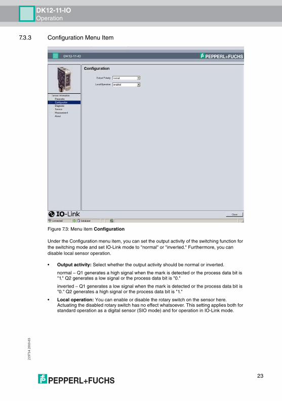
Figure 7.3: Menu item Configuration
Under the Configuration menu item, you can set the output activity of the switching function for the switching mode and set IO-Link mode to "normal" or "inverted." Furthermore, you can disable local sensor operation.
• Output activity: Select whether the output activity should be normal or inverted.
normal – Q1 generates a high signal when the mark is detected or the process data bit is "1." Q2 generates a low signal or the process data bit is "0."
inverted – Q1 generates a low signal when the mark is detected or the process data bit is "0." Q2 generates a high signal or the process data bit is "1."
• Local operation: You can enable or disable the rotary switch on the sensor here. Actuating the disabled rotary switch has no effect whatsoever. This setting applies both for standard operation as a digital sensor (SIO mode) and for operation in IO-Link mode.
23

DK12-11-IOOperation
2197
14 2
010-
03
7.3.4 Diagnosis Menu Item
Figure 7.4: Menu item Diagnosis
The Diagnosis menu item is divided into three areas.
• Process date: Displays the current output value (process date). This is a read-only field.
• Device diagnosis: Displays the device status and the last result. These are read-only fields.
• Local operating elements: Graphical representation of the sensor indicating the switching status and the current position of the rotary switch. The fields are read-only fields.
24

DK12-11-IOOperation
2197
14 2
010-
03
7.3.5 Service menu item
Figure 7.5: Menu item Service
The Diagnosis menu item is divided into three areas.
• Service: The following options are available:
• Locator display: Activating the locator function causes the indicator LEDs to flash in a specific rhythm. This feature allows you to localize a sensor in a system more easily. The illustration of the sensor on the right shows how the LEDs are switched.
• Sensor test mode: Test function for the transmitter LEDs. This function is used to check whether all transmitter colors on the transmitter LED are available. The selected color is also displayed in the sensor illustration. Measurement is not possible during this time.
• Default setting: You can reset the sensor settings to default by pressing the assigned Reset button. All previous parameters changes are lost.
• Device version: Display of the firmware and hardware version. If you have problems with the sensor and have to contact the Service Center, you will need these numbers. The fields are read-only fields.
• IO-Link communication parameters: Display of IO-Link specific communication information. The fields are read-only fields.
25

DK12-11-IOOperation
2197
14 2
010-
03
7.3.6 Service Menu Item
The Measurement menu item displays completed measurements in the form of graphs.
• OUT button: Output of measured values.
• Measurement: Select the relevant measuring cycle here.
• Save: You can save completed measurements here.
• Load: You can load saved measurements to the output window.
• Start button: You can use the Start button to start a measurement.
• Output window: The measured values are displayed in a graph in the output window. You can change the scaling of the x-axis and y-axis by pressing the left, right or both mouse buttons simultaneously.
26

DK12-11-IOOperation
2197
14 2
010-
03
7.3.7 About Menu Item
Figure 7.6: Menu item About
Information about the device, DTM version and creation date. If you have problems with the sensor and have to contact the Service Center, you will need this information see chapter 8.1.
27

2197
14 2
010-
03
28
DK12-11-IOTroubleshooting
8 Troubleshooting
8.1 What to do in the event of an error
Before requesting a service call, please check that the following actions have been taken:
• Test the equipment according to the following checklist,
• Call the Service Center for assistance in order to isolate the problem.
Checklist
• If none of the above solves the problem, contact the Service Center. Have the model number and firmware version of the sensor ready if possible, view Figure 7.5 on page 25 and view Figure 7.6 on page 27.
Error Cause Remedy
"Operating indicator" LED does not light up
The power supply is switched off.
Check whether there is a reason for it being switched off (installation or maintenance work etc.). Switch the power supply on if appropriate.
"Operating indicator" LED does not light up
The 4-pin M12 plug is not connected to the connector on the sensor.
Connect the 4-pin M12 plug to the sensor and tighten the cap nut by hand.
"Operating indicator" LED does not light up
Wiring fault in the splitter or control cabinet.
Check the wiring carefully and repair any wiring faults.
"Operating indicator" LED does not light up
Supply cable to the sensor is damaged.
Replace the damaged cable.
No IO-Link connection to the device
The C/Q communication port on the sensor is not connected to the IO-Link master
Make sure that the C/Q communication port is connected to the IO-Link master.
No IO-Link connection to the device
No power supply See error "Operating indicator" LED does not light up
Manual adjustment option not available on the device
Local operation has been deactivated using the software.
Activate local operation using the software see chapter 7.3.3.
Print marks and/or background are not detected cleanly
Sensor is too close or too far from the reading point.Incorrect print marks and/or background taught in.
Check the mounting and teach in the print marks and/or background again.
DK12-11-IO

DK12-11-IOAppendix
2197
14 2
010-
03
DK12-11-IO
9 Appendix
9.1 IO-Link Flow Diagrams
The following examples show the steps required to communicate with an IO-Link sensor for different tasks. The sensor must be operating in IO-Link mode.
Start-up
Figure 9.1: Flow diagram Start-up
Possible procedure for device validation using an IO-Link master.
Start
>id's>ok?
yes
yes
no
no Comparison whether proper equipmentand configuration
read <user tag1>read <user tag2>
DeviceError
ConfigurationErrorEND
<user tag>ok?
read <direct parameter/vendor +device id>
29

DK12-11-IOAppendix
2197
14 2
010-
03
Commissioning
Figure 9.2: Flow diagram Commissioning
A typical procedure for commissioning via IO-Link.
Commissioning
End
read <direct parameter/vendor +device id>
write <output polarity control>
write <applicationspecific name>
write <user tag>
write <local operationcontrol = disable>
Unique device identification for target configuration
Clear labeling of the device in the application
30

DK12-11-IOAppendix
2197
14 2
010-
03
Reading (Saving) the Job Configuration
Figure 9.3: Flow diagram Reading (saving) a job configuration
A typical procedure for reading and saving a job configuration.
Read job configuration
End
read <user tag
read <teach value mark>
read <teach value backgnd>
read <output polarity control>
Clear marking of the configuration
31

DK12-11-IOAppendix
2197
14 2
010-
03
Writing the Job Configuration
Figure 9.4: Flow diagram IO-Link Writing the job configuration
A typical procedure for writing a job configuration.
WritingJob configuration
End
read <user tag>
write <teach value mark>
write <teach value backgnd>
write <output polarity control>
write <teach mode = evaluate>
Comparison in control before writing the data whether real device
Examination of the Teach Values
write <teach mode = operate> Activation of the configuration
32
DK12-11-IOAppendix
2197
14 2
010-
03
Teach-in via IO-Link (Remote)
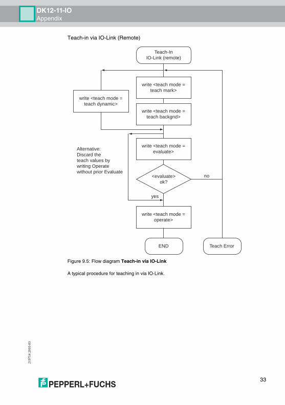
Figure 9.5: Flow diagram Teach-in via IO-Link
A typical procedure for teaching in via IO-Link.
Teach-InIO-Link (remote)
yes
no
Alternative:Discard the teach values by writing Operate without prior Evaluate
END Teach Error
<evaluate>ok?
write <teach mode =teach mark>
write <teach mode =teach dynamic>
write <teach mode =teach backgnd>
write <teach mode =evaluate>
write <teach mode =operate>
33
DK12-11-IOAppendix
2197
14 2
010-
03
Local Teach-In in IO-Link Mode (Local)
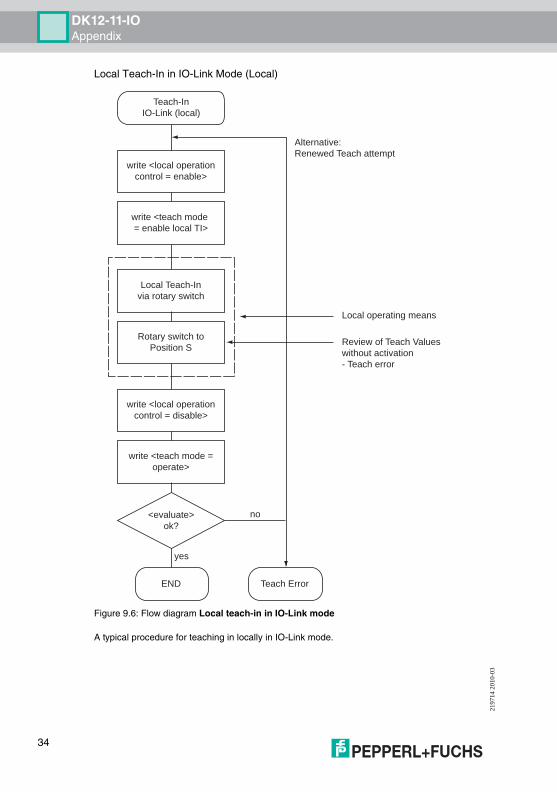
Figure 9.6: Flow diagram Local teach-in in IO-Link mode
A typical procedure for teaching in locally in IO-Link mode.
Teach-InIO-Link (local)
yes
no
Alternative:Renewed Teach attempt
Local operating means
Review of Teach Valueswithout activation- Teach error
END Teach Error
<evaluate>ok?
write <local operationcontrol = enable>
write <teach mode = enable local TI>
Local Teach-Invia rotary switch
write <local operationcontrol = disable>
write <teach mode =operate>
Rotary switch toPosition S
34

DK12-11-IOAppendix
2197
14 2
010-
03
9.2 Telegram Types
9.2.1 Standard Parameter Data
The sensor can be parameterized via the SPDU data channel. Readable addresses include:
Index hex decimal Name Type Data type Value
0x02 2 System command W unsigned integer 8 0x81 Reset application0x82 Reset default setting
0x10 16 Manufacturer name
R String Pepperl+Fuchs GmbH
0x11 17 Manufacturer text R String http://www.pepperl-fuchs.com
0x12 18 Product name R String DK12-11-IO/92/136
0x13 19 Product ID R String Article number
0x14 20 Product text R String DK12 contrast sensor
0x15 21 Series number R String [Length = 16]
00 000 000000 000 00
0x16 22 Hardware revision R String <Release code> HW00.90
0x17 23 Firmware revision R String <Release code> FW00.70
0x18 24 Specific name in the application
Read/write
String [max. length = 24]
<user string (var.length)>
0x20 32 Error counter R unsigned integer 16 Events since switching on last
0x21 33 Last event R Record See IOL spec.
0x24 36 Device status R unsigned integer 8 0x00
0x28 40 Process data input R unsigned integer 8 0x00 no detection0x01 detection
35

DK12-11-IOAppendix
2197
14 2
010-
03
9.2.2 DK12-Specific Parameters
The following parameters are used to parameterize, configure and diagnose functions specific to the DK12-11-IO.
Index hex decimal Name Type Data type Value
0x50 80 Threshold value (on) R unsigned integer 8 0x00 - 0xff
0x51 81 Threshold value (off) R unsigned integer 8 0x00 - 0xff
0x54 84 Polarity contrast switch R unsigned integer 8 0x00 - on above threshold value0x00 - on below threshold value
0x55 85 Transmitter color R unsigned integer 8 0x00 - off0x01 - red0x02 - green0x03 - blue0x04 - all (white)
0x68 104 Teach mode Read/write
unsigned integer 8 0x00 - operate0x01 - teach M0x02 - teach B0x03 - teach dynamic0x0F - evaluate0x1F - enable local teach-in
0x69 105 Teach result R Record 2 entries
sub1 Teach status R unsigned integer 8 0bX0XX 0000 - no new value0bX0XX 0001 - new value M0bX0XX 0010 - new value B0bX0XX 0011 - new value M+B0bX0X1 XXXX- local teach-in active0b0010 0000 - sensor test operation0b10XX XXXX- teach fail
sub2 Teach quality factor R unsigned integer 8 0x00 - 0x64 (see definition)
0x6A 106 Teach value M (RGB) Read/write
Record 3 entries
sub1 Red intensity M Read/write
unsigned integer 8 0x00 - 0xFF
sub2 Green intensity M Read/write
unsigned integer 8 0x00 - 0xFF
sub3 Blue intensity M Read/write
unsigned integer 8 0x00 - 0xFF
0x6B 107 Teach value B (RGB) Read/write
Record 3 entries
sub1 Red intensity B Read/write
unsigned integer 8 0x00 - 0xFF
sub2 Green intensity B Read/write
unsigned integer 8 0x00 - 0xFF
sub3 Blue intensity B Read/write
unsigned integer 8 0x00 - 0xFF
36

DK12-11-IOAppendix
2197
14 2
010-
03
0x70 112 Output mode control (L/D on)
Read/write
unsigned integer 8 == 0x00 - normal (default)<> 0x00 - inverted
0x71 113 Local operation control (local lockout)
Read/write
unsigned integer 8 == 0x00 - enabled (default)<> 0x00 - disabled
0x72 114 Sensor operation control (test function)
Read/write
unsigned integer 8 == 0x00 - normal operation (default)== 0x01 - test emitter red== 0x02 - test emitter green== 0x03 - test emitter blue== 0x04 - test emitter off
0x73 115 Local control status R unsigned integer 8 0xX0 - switch setting S0xX1 - switch setting TM0xX2 - switch setting TB0xX3 - switch setting TD0x0X - local operation enabled0x1X - local operation disabled
0x7F 127 Locator indication control
Read/write
unsigned integer 8 == 0x00 - normal indication (default)<> 0x00 - locator indication
0xC0 192 User tag 1 Read/write
octet string [4] user defined code0x00 00 00 00 - default
0xC1 193 User tag 2 Read/write
octet string [2] user defined code0x00 00 - default
0xED 237 Direct parameter 0 - 15 R octet string [16]
Index hex decimal Name Type Data type Value
37

DK12-11-IOAppendix
2197
14 2
010-
03
9.2.3 Error Codes
In the event of a fault, the sensor transmits the following error codes:
Error code Instance Code Note
No error APP ZERO Only applies for response telegram
Unspecific application fault APP 0x8000
Invalid index APP 0x8011
Invalid subindex APP 0x8012
Service temporarily unavailable
APP 0x8020
Service temporarily unavailable (control)
APP 0x8021
Service temporarily unavailable (sensor)
APP 0x8022
Access denied APP 0x8023 Write attempt to read-only address
Invalid value range, parameter
APP 0x8030
Parameter value too large APP 0x8031
Parameter value too small APP 0x8032
Application error APP 0x8081 Application does not respond
Application not ready APP 0x8082 Application does not respond
38

DK12-11-IOAppendix
2197
14 2
010-
03
9.2.4 Result Data
The sensor is capable of transmitting events that occur:
Event Instance Type ModeEvent qualifier
Event code Description
PDU buffer overflow
DL Error Single shot
0x72 0x5200 Sensor cannot process the transmitted data object due to the size
PDU checksum error
DL Error Single shot
0x72 0x5600 Inconsistency during transmission of the PDU data
PDU process errorPDU flow control error
DL Error Single shot
0x72 0x5600 Asynchronicity during transmission of the PDU data
Unauthorized PDU service
AL Error Single shot
0x73 0x5800 Transmitted service request is invalid
Parameter error
APP Error Single shot
0x74 0x6320 Inconsistent parameter set
Parameter modified
APP Message
Single shot
0x54 0x6350 New parameter
Internal error APP Error Appear 0xF4 0x8CF0 Internal communication
Internal error APP Error Disappear 0xB4 0x8CF0 Timeout
39

Pepperl+Fuchs sets the standard in quality and innovative technology for the world of automation. Our expertise, dedica-tion, and heritage of innovation have driven us to develop the largest and most versatile line of industrial sensor technolo-gies and interface components in the world. With our global presence, reliable service, and flexible production facilities, Pepperl+Fuchs delivers complete solutions for your automation requirements – wherever you need us.
www.pepperl-fuchs.com
Worldwide HeadquartersPepperl+Fuchs GmbH · Mannheim · GermanyE-mail: [email protected]
USA HeadquartersPepperl+Fuchs Inc. · Twinsburg, OH · USAE-mail: [email protected]
Asia Pacific HeadquartersPepperl+Fuchs Pte Ltd · SingaporeCompany Registration No. 199003130EE-mail: [email protected]
FACTORY AUTOMATION – SENSING YOUR NEEDS
ContactPepperl+Fuchs GmbHLilienthalstraße 20068307 Mannheim · GermanyTel. +49 621 776-4411 · Fax +49 621 776-27-4411E-mail: [email protected]
Subject to reasonable modifications due to technical advancesCopyright Pepperl+Fuchs • Printed in Germany
219714 / TDOCT1823__ENG03/2010