manual devolo magic2wifi 2-1 · with a plc-(powerline communication) and/or a wi-fi module....
TRANSCRIPT

Manualdevolo Magic2 WiFi 2-1

devolo Magic 2 WiFi 2-1

© 2018 devolo AG Aachen (Deutschland) While the information in this manual has been compiled with great care, it may not be deemed an assurance of product characteristics. devolo shallbe liable only to the degree specified in the terms of sale and delivery.The reproduction and distribution of the documentation and software supplied with this product and the use of its contents is subject to written au-thorization from devolo. We reserve the right to make any alterations that arise as the result of technical development.
TrademarksAndroid TM is a registered trademark of Open Handset Alliance.Linux® is a registered trademark of Linus Torvalds.Ubuntu®is a registered trademark of Canonical Ltd. Mac® and Mac OS X® are registered trademarks of Apple Computer, Inc.iPhone®,iPad® and iPod® are registered trademarks of Apple Computer, Inc.
Windows® and Microsoft® are registered trademarks of Microsoft, Corp.devolo, dLAN® and the devolo logo are registered trademarks of devolo AG. All other names mentioned may be trademarks or registered trademarks of their respective owners. Subject to change without notice. No liability fortechnical errors or omissions.
devolo AGCharlottenburger Allee 6752068 AachenDeutschlandwww.devolo.com
Aachen, September 2018
Version 1.0

Contents1 Preface . . . . . . . . . . . . . . . . . . . . . . . . . . . . . . . . . . . . . . . . . . . . . . . . . . . . . . . . . . . . . . . . . . . . . . . . . . . . . . . . . . . . . . . 6
1.1 About this manual . . . . . . . . . . . . . . . . . . . . . . . . . . . . . . . . . . . . . . . . . . . . . . . . . . . . . . . . . . . . . . . . . . . . . . . . . . .61.2 Intended use . . . . . . . . . . . . . . . . . . . . . . . . . . . . . . . . . . . . . . . . . . . . . . . . . . . . . . . . . . . . . . . . . . . . . . . . . . . . . . .71.3 CE Conformity . . . . . . . . . . . . . . . . . . . . . . . . . . . . . . . . . . . . . . . . . . . . . . . . . . . . . . . . . . . . . . . . . . . . . . . . . . . . . .81.4 Safety notes . . . . . . . . . . . . . . . . . . . . . . . . . . . . . . . . . . . . . . . . . . . . . . . . . . . . . . . . . . . . . . . . . . . . . . . . . . . . . . . .81.5 devolo on the Internet . . . . . . . . . . . . . . . . . . . . . . . . . . . . . . . . . . . . . . . . . . . . . . . . . . . . . . . . . . . . . . . . . . . . . . .9
2 Introduction . . . . . . . . . . . . . . . . . . . . . . . . . . . . . . . . . . . . . . . . . . . . . . . . . . . . . . . . . . . . . . . . . . . . . . . . . . . . . . . . . 102.1 devolo Magic . . . . . . . . . . . . . . . . . . . . . . . . . . . . . . . . . . . . . . . . . . . . . . . . . . . . . . . . . . . . . . . . . . . . . . . . . . . . . 102.2 The devolo Magic 2 WiFi . . . . . . . . . . . . . . . . . . . . . . . . . . . . . . . . . . . . . . . . . . . . . . . . . . . . . . . . . . . . . . . . . . . 112.3 Pairing – Establishing a PLC connection . . . . . . . . . . . . . . . . . . . . . . . . . . . . . . . . . . . . . . . . . . . . . . . . . . . . . . . 13
2.3.1 Reading the PLC indicator light . . . . . . . . . . . . . . . . . . . . . . . . . . . . . . . . . . . . . . . . . . . . . . . . . . . . . . 142.3.2 WiFi button . . . . . . . . . . . . . . . . . . . . . . . . . . . . . . . . . . . . . . . . . . . . . . . . . . . . . . . . . . . . . . . . . . . . . . . 172.3.3 Reading the WiFi indicator light . . . . . . . . . . . . . . . . . . . . . . . . . . . . . . . . . . . . . . . . . . . . . . . . . . . . . . 182.3.4 Reset button . . . . . . . . . . . . . . . . . . . . . . . . . . . . . . . . . . . . . . . . . . . . . . . . . . . . . . . . . . . . . . . . . . . . . . 192.3.5 Network jacks . . . . . . . . . . . . . . . . . . . . . . . . . . . . . . . . . . . . . . . . . . . . . . . . . . . . . . . . . . . . . . . . . . . . . 202.3.6 WiFi antennas . . . . . . . . . . . . . . . . . . . . . . . . . . . . . . . . . . . . . . . . . . . . . . . . . . . . . . . . . . . . . . . . . . . . . 202.3.7 Integrated electrical socket . . . . . . . . . . . . . . . . . . . . . . . . . . . . . . . . . . . . . . . . . . . . . . . . . . . . . . . . . . 20
3 Initial use . . . . . . . . . . . . . . . . . . . . . . . . . . . . . . . . . . . . . . . . . . . . . . . . . . . . . . . . . . . . . . . . . . . . . . . . . . . . . . . . . . . . 213.1 Package contents . . . . . . . . . . . . . . . . . . . . . . . . . . . . . . . . . . . . . . . . . . . . . . . . . . . . . . . . . . . . . . . . . . . . . . . . . 213.2 System requirements . . . . . . . . . . . . . . . . . . . . . . . . . . . . . . . . . . . . . . . . . . . . . . . . . . . . . . . . . . . . . . . . . . . . . . 213.3 Connecting the devolo Magic 2 WiFi . . . . . . . . . . . . . . . . . . . . . . . . . . . . . . . . . . . . . . . . . . . . . . . . . . . . . . . . . . 22
3.3.1 Starter Kit – Automatic set-up for a new devolo Magic PLC network . . . . . . . . . . . . . . . . . . . . . . . . 223.3.2 Addition – Expanding an existing PLC network by adding another devolo Magic 2 WiFi . . . . . . . 233.3.3 Changing the network password . . . . . . . . . . . . . . . . . . . . . . . . . . . . . . . . . . . . . . . . . . . . . . . . . . . . . 233.3.4 Integrating the devolo Magic 2 WiFi into an existing WiFi network . . . . . . . . . . . . . . . . . . . . . . . . 23
3.4 Installation of devolo software . . . . . . . . . . . . . . . . . . . . . . . . . . . . . . . . . . . . . . . . . . . . . . . . . . . . . . . . . . . . . . 243.5 Removing the devolo Magic adapter from a PLC network . . . . . . . . . . . . . . . . . . . . . . . . . . . . . . . . . . . . . . . . 24
devolo Magic 2 WiFi

4 Network configuration . . . . . . . . . . . . . . . . . . . . . . . . . . . . . . . . . . . . . . . . . . . . . . . . . . . . . . . . . . . . . . . . . . . . . . . . 264.1 Calling up the built-in web interface . . . . . . . . . . . . . . . . . . . . . . . . . . . . . . . . . . . . . . . . . . . . . . . . . . . . . . . . . . 264.2 General information about the menu . . . . . . . . . . . . . . . . . . . . . . . . . . . . . . . . . . . . . . . . . . . . . . . . . . . . . . . . . 264.3 Overview . . . . . . . . . . . . . . . . . . . . . . . . . . . . . . . . . . . . . . . . . . . . . . . . . . . . . . . . . . . . . . . . . . . . . . . . . . . . . . . . 284.4 WiFi . . . . . . . . . . . . . . . . . . . . . . . . . . . . . . . . . . . . . . . . . . . . . . . . . . . . . . . . . . . . . . . . . . . . . . . . . . . . . . . . . . . . . 29
4.4.1 Status . . . . . . . . . . . . . . . . . . . . . . . . . . . . . . . . . . . . . . . . . . . . . . . . . . . . . . . . . . . . . . . . . . . . . . . . . . . . 304.4.2 WiFi networks . . . . . . . . . . . . . . . . . . . . . . . . . . . . . . . . . . . . . . . . . . . . . . . . . . . . . . . . . . . . . . . . . . . . . 314.4.3 Guest network . . . . . . . . . . . . . . . . . . . . . . . . . . . . . . . . . . . . . . . . . . . . . . . . . . . . . . . . . . . . . . . . . . . . 334.4.4 Mesh . . . . . . . . . . . . . . . . . . . . . . . . . . . . . . . . . . . . . . . . . . . . . . . . . . . . . . . . . . . . . . . . . . . . . . . . . . . . 344.4.5 Schedule control . . . . . . . . . . . . . . . . . . . . . . . . . . . . . . . . . . . . . . . . . . . . . . . . . . . . . . . . . . . . . . . . . . . 364.4.6 WiFi Protected Setup (WPS) . . . . . . . . . . . . . . . . . . . . . . . . . . . . . . . . . . . . . . . . . . . . . . . . . . . . . . . . . 374.4.7 Neighbour networks . . . . . . . . . . . . . . . . . . . . . . . . . . . . . . . . . . . . . . . . . . . . . . . . . . . . . . . . . . . . . . . 39
4.5 Powerline . . . . . . . . . . . . . . . . . . . . . . . . . . . . . . . . . . . . . . . . . . . . . . . . . . . . . . . . . . . . . . . . . . . . . . . . . . . . . . . . 404.6 LAN . . . . . . . . . . . . . . . . . . . . . . . . . . . . . . . . . . . . . . . . . . . . . . . . . . . . . . . . . . . . . . . . . . . . . . . . . . . . . . . . . . . . . 43
4.6.1 Status . . . . . . . . . . . . . . . . . . . . . . . . . . . . . . . . . . . . . . . . . . . . . . . . . . . . . . . . . . . . . . . . . . . . . . . . . . . . 434.6.2 IPv4/IPv6 configuration . . . . . . . . . . . . . . . . . . . . . . . . . . . . . . . . . . . . . . . . . . . . . . . . . . . . . . . . . . . . . 43
4.7 System . . . . . . . . . . . . . . . . . . . . . . . . . . . . . . . . . . . . . . . . . . . . . . . . . . . . . . . . . . . . . . . . . . . . . . . . . . . . . . . . . . 444.7.1 Status . . . . . . . . . . . . . . . . . . . . . . . . . . . . . . . . . . . . . . . . . . . . . . . . . . . . . . . . . . . . . . . . . . . . . . . . . . . . 444.7.2 Management . . . . . . . . . . . . . . . . . . . . . . . . . . . . . . . . . . . . . . . . . . . . . . . . . . . . . . . . . . . . . . . . . . . . . 454.7.3 Configuration . . . . . . . . . . . . . . . . . . . . . . . . . . . . . . . . . . . . . . . . . . . . . . . . . . . . . . . . . . . . . . . . . . . . . 464.7.4 Firmware . . . . . . . . . . . . . . . . . . . . . . . . . . . . . . . . . . . . . . . . . . . . . . . . . . . . . . . . . . . . . . . . . . . . . . . . . 464.7.5 Config Sync . . . . . . . . . . . . . . . . . . . . . . . . . . . . . . . . . . . . . . . . . . . . . . . . . . . . . . . . . . . . . . . . . . . . . . . 47
5 Appendix . . . . . . . . . . . . . . . . . . . . . . . . . . . . . . . . . . . . . . . . . . . . . . . . . . . . . . . . . . . . . . . . . . . . . . . . . . . . . . . . . . . . 485.1 Technical specifications . . . . . . . . . . . . . . . . . . . . . . . . . . . . . . . . . . . . . . . . . . . . . . . . . . . . . . . . . . . . . . . . . . . . 485.2 Frequency range and transmitting power . . . . . . . . . . . . . . . . . . . . . . . . . . . . . . . . . . . . . . . . . . . . . . . . . . . . . 485.3 Channels and carrier frequencies . . . . . . . . . . . . . . . . . . . . . . . . . . . . . . . . . . . . . . . . . . . . . . . . . . . . . . . . . . . . 495.4 Bandwidth optimization . . . . . . . . . . . . . . . . . . . . . . . . . . . . . . . . . . . . . . . . . . . . . . . . . . . . . . . . . . . . . . . . . . . . 505.5 Disposal of old devices . . . . . . . . . . . . . . . . . . . . . . . . . . . . . . . . . . . . . . . . . . . . . . . . . . . . . . . . . . . . . . . . . . . . . 515.6 Warranty conditions . . . . . . . . . . . . . . . . . . . . . . . . . . . . . . . . . . . . . . . . . . . . . . . . . . . . . . . . . . . . . . . . . . . . . . . 51
devolo Magic 2 WiFi

Preface 6
1 PrefaceWelcome to the fantastic world of devolo Magic!
In no time at all, devolo Magic transforms your house intoa multimedia home that is ready for the future today.devolo Magic gives you noticeably higher speeds, morestability and greater range, providing the perfect Internetexperience as a result!
1.1 About this manualCarefully read all instructions before setting up the deviceand store the manual and/or installation guide for later re-ference.
After a brief introduction to „devolo Magic“ and to thedevolo Magic in Chapter 2, Chapter 3 tells you how tosuccessfully start using the adapter in your network.
Chapter 4 describes in detail the setting options of thebuilt-in devolo Magic configuration interface.
Tips for bandwidth optimisation, information about env-ironmental compatibility of the device, as well as our war-ranty terms, can be found in Chapter 5 at the end of themanual.
Description of the icons
This section contains a brief description of the icons used inthis manual and/or on the rating plate, the device connec-tor, as well as the icons used on the package:
Icon Description
Very important safety symbol that warnsyou of imminent electrical voltage whichif not observed can result in serious injuryor death.
An important safety symbol that warnsyou of a potentially dangerous situationinvolving a burn hazard which can resultin minor injuries or damage to property.
An important note that should be obser-ved which can potentially lead to materi-al damages.
The device may only be used indoors indry conditions.
devolo Magic 2 WiFi

7 Preface
1.2 Intended useUse devolo products, devolo software and the provided ac-cessories as described to prevent damage and injury.
Productsdevolo products are communication devices designed forindoors.* Depending on the product, they are equippedwith a PLC- (PowerLine Communication) and/or a Wi-Fimodule. Computers, laptops, smartphones, tablets, smartTVs and other devices connected this way are integratedinto a home network over the existing electrical wiringand/or Wi-Fi without any complicated wiring. devolo de-vices must never be used outdoors because the high tem-perature fluctuations and moisture can damage both theproduct and the power line. devolo products may not be in-stalled at a height above two metres unless an additionalfas-tening mechanism is available. The products are inten-ded for operation in the EU, Switzerland and Norway.
* The only exceptions are devolo outdoor products, whichare suited for the outdoor use thanks to their IP certificati-on.
Softwaredevolo devices can be used only with the free, downloada-ble programs approved and available on devolo AG's web-site (www.devolo.com) and in app stores (iOS and GooglePlay). Any modifications to the product-specific firmware
The manufacturer/distributing companyuses the CE marking to declare that theproduct meets all applicable Europeanregulations and has been subjected tothe prescribed conformity assessmentprocedures.
It is used to prevent the occurrence of wa-ste electrical and electronic equipmentand to reduce this type of waste throughreuse, recycling and other forms of utili-sation. The European Community WEEEDirective establishes minimum stan-dards for handlingwaste electrical and electronic equip-ment in the EU.
Additional information, background ma-terial and configuration tips for your de-vice.
Indicates a completed course of action
Icon Description
devolo Magic 2 WiFi

Preface 8
or software could damage the products and, in the worst-case scenario, render them unusable and negatively affectconformity.
Always use the most up-to-date software version to makesure you have the latest security functions and device up-dates. The installed devolo software notifies you automati-cally if a new software version is available.
AccessoriesUse only the provided accessories:
Network cable: RJ45-RJ45 Cat-5e UTP
1.3 CE ConformityThis product complies with the technical require-ments of the directives 2014/35/EU, 2014/30/EU, 2011/65/EU und 2009/125/EC.
This product is designed for use in the EU, Switzer-land and Norway.
A printout of the simplified CE declaration of this product isseparately included and can also be found under www.devolo.com/support/ce.
1.4 Safety notesIt is essential to have read and understood all safety andoperating instructions before the devolo device is used forthe first time; keep them safe for future reference.
DANGER! Electrical shock caused by electricityDo not reach into the electrical socket, do notopen the device and do not insert any objectsinto the electrical socket or into the ventilationopenings
Users do not need to carry out any maintenance on devolodevices. In the event of damage, disconnect the devolo de-vice from the mains supply by pulling it or its plug out ofthe electrical socket. Then contact qualified specialist per-sonnel (after-sales service) exclusively. Damage is dee-med to have occurred, for example,
if the power plug is damaged.if the devolo device has been showered with liquid(such as rain or other water).if the devolo device is inoperable.if the housing of the devolo device is damaged.Do not plug devolo devices directly into each other.Devices that are plugged into each other can experi-ence a decrease in transmission rate.
devolo Magic 2 WiFi

9 Preface
DANGER! Electric shock caused by electricityDevice must be plugged into a power socketwith a connected earth wire
devolo devices may be operated only on a mains powersupply as described on the rating plate.
To disconnect devolo devices from the mains supply, un-plug the device from the electrical socket.
The power socket and all connected network devicesshould be easily accessible so that you can pull the po-wer plug quickly if needed.
CAUTION! Heat development during operationCertain housing components can become veryhot in certain situations. Attach device so thatit is touch-proof, observing optimal positio-ning
devolo devices should only be installed at locations thatguarantee adequate ventilation. Slots and openings on thehousing are used for ventilation:
Do not cover devolo devices during operation.Do not place any objects on devolo devices.Do not insert any objects into the openings of devolodevices. devolo devices must not be placed directly next to anaked flame (such as fire or candles).
devolo devices must not be exposed to direct heatradiation (e.g. radiator, direct sunlight).
CAUTION! Damage to housing from cleaningagents containing solventsClean only electroless and with dry cloth
1.5 devolo on the InternetFor detailed information on our products anddevolo Magic, visit www.devolo.com.
There you will find product descriptions and documentati-on, and also updates of devolo software and your device'sfirmware.
If you have any further ideas or suggestions related to ourproducts, please don't hesitate to contact us [email protected]!
devolo Magic 2 WiFi

Introduction 10
2 Introduction
2.1 devolo MagicHome is where devolo Magic is – in no time at all,devolo Magic transforms your house or flat into a multime-dia home of the future with noticeably higher speed, more
stability and greater range, providing the perfect Internetexperience as a result!
Be inspired by products that are astonishingly easy to in-stall, with impressive, innovative technology and unbea-table performance.
Fig. 1 devolo Magic throughout the home
devolo Magic 2 WiFi

11 Introduction
The product name concept The devolo Magic name concept has the followingstructure:
Be ready for the technology of the future today
devolo Magic embodies the new generation of the tried-and-tested Powerline technology (PLC) based on the cut-ting-edge G.hn architecture. G.hn was developed by the In-ternational Telecommunication Union (ITU) with ongoingdevelopment provided primarily by the HomeGrid Forumindustry association. devolo Magic products are certifiedaccording to HomeGrid standards and are compatible withother HomeGrid-certified products.
Like the HomePlug AV technology used in established de-volo dLAN devices, devolo Magic uses the householdmains supply for data transmission and secures ideal per-formance and stability in locations where network cables
are not viable or desired and/or the WiFi frequently fallsshort due to ceilings and walls.
To set up a devolo Magic network, you need at leasttwo devolo Magic devices. For technical reasons, de-vices from the devolo Magic series are not compatib-le with dLAN devices.
2.2 The devolo Magic 2 WiFiA brief introduction to the devolo Magic adapter:
Unpack– plug in – get started and be prepared for thenew generation of the tried-and-tested Powerlinetechnology and innovative mesh WiFi with swiftnessand stability:
Powerline At speeds up to 2400 MbpsOver distances up to 500 metresSecurity – with 128-bit AES Powerline encryption
Mesh WiFi At speeds up to 1200 MbpsFour antennas cover the 2.4 and 5 GHz WiFi frequen-cies at the same time and use the full extent of theentire 5 GHz frequency band (Dynamic FrequencySelection, DFS).
Product family devolo MagicPerformance catego-ry
2
Transmission type WiFiNumber of sockets 2Integrated electricalsocket
1 (= yes)
devolo Magic 2 WiFi
Introduction 12
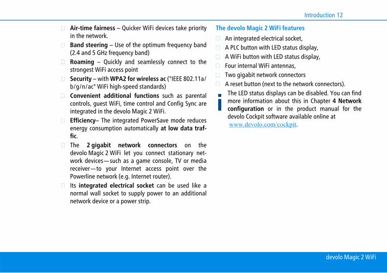
Air-time fairness – Quicker WiFi devices take priorityin the network. Band steering – Use of the optimum frequency band(2.4 and 5 GHz frequency band)Roaming – Quickly and seamlessly connect to thestrongest WiFi access pointSecurity – with WPA2 for wireless ac ("IEEE 802.11a/b/g/n/ac" WiFi high-speed standards) Convenient additional functions such as parentalcontrols, guest WiFi, time control and Config Sync areintegrated in the devolo Magic 2 WiFi.Efficiency– The integrated PowerSave mode reducesenergy consumption automatically at low data traf-fic.The 2 gigabit network connectors on thedevolo Magic 2 WiFi let you connect stationary net-work devices—such as a game console, TV or mediareceiver—to your Internet access point over thePowerline network (e.g. Internet router).Its integrated electrical socket can be used like anormal wall socket to supply power to an additionalnetwork device or a power strip.
The devolo Magic 2 WiFi features An integrated electrical socket,A PLC button with LED status display,A WiFi button with LED status display,Four internal WiFi antennas,Two gigabit network connectorsA reset button (next to the network connectors).The LED status displays can be disabled. You can findmore information about this in Chapter 4 Networkconfiguration or in the product manual for thedevolo Cockpit software available online at www.devolo.com/cockpit.
devolo Magic 2 WiFi

13 Introduction
2.3 Pairing – Establishing a PLC connec-tion
devolo Magic adapters that are in the factory default con-dition, i.e. have been recently purchased or successfully re-set (see Chapter 3.5 Removing the devolo Magicadapter from a PLC network), automatically start to at-tempt to pair (establish a PLC connection) withanotherdevolo Magic adapter when reconnected to themains supply.
Starting up a new devolo Magic PLC networkAfter plugging the devolo Magic adapters into availablepower sockets, a new devolo Magic network is establishedautomatically within 3 minutes.
Fig. 2: devolo Magic 2 WiFi with country-specific connector and power socket
Fig. 3 Network connectors
devolo Magic 2 WiFi

Introduction 14
Expanding an existing devolo Magic PLC network by adding another devolo Magic adapterIn order to use a new devolo Magic 2 WiFi in yourdevolo Magic- network, first you have to connect it to yourexisting devolo Magic adapters devices as a network. Thisis accomplished by using a shared PLC password, whichcan be assigned in various ways:
Using devolo Cockpit or the devolo app (see Chapter3.4 Installation of devolo software) Using the web interface (see Chapter 4.5 Powerline)Using the PLC button as described below.
To do so, plug the new devolo Magic adapter into anavailable power socket and, for approximately1 second, press the PLC button on a devolo Magicadapter in your existing devolo Magic network.
For each pairing operation, only one additionaldevolo Magic adapter can be added at a time.
Within 3 minutes, press the PLC button on thedevolo Magic adapter that you want to add to yourexisting devolo Magic network. The LED of this adap-ter now also flashes white.
After a short time, the flashing LED becomes asteady white light. The devolo Magic adapter hasbeen successfully integrated into your existingdevolo Magic network.
You can find detailed information about installingdevolo Magic adapters in Chapter 3.3 Connectingthe devolo Magic 2 WiFi.
2.3.1 Reading the PLC indicator lightThe integrated PLC indicator light (LED) shows the statusfor the devolo Magic 2 WiFi by illuminating and/or flas-hing:
LED Flashing be-haviour
Meaning LED status display(web interface*)
1 Red LED Lights up for upto 2 sec.
Start-up process Cannot be disabled
devolo Magic 2 WiFi
15 Introduction
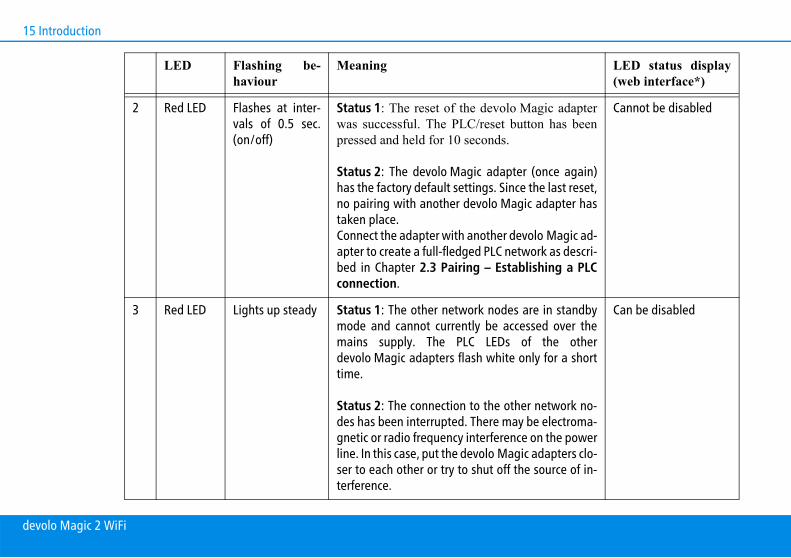
2 Red LED Flashes at inter-vals of 0.5 sec.(on/off)
Status 1: The reset of the devolo Magic adapterwas successful. The PLC/reset button has beenpressed and held for 10 seconds.
Status 2: The devolo Magic adapter (once again)has the factory default settings. Since the last reset,no pairing with another devolo Magic adapter hastaken place. Connect the adapter with another devolo Magic ad-apter to create a full-fledged PLC network as descri-bed in Chapter 2.3 Pairing – Establishing a PLCconnection.
Cannot be disabled
3 Red LED Lights up steady Status 1: The other network nodes are in standbymode and cannot currently be accessed over themains supply. The PLC LEDs of the otherdevolo Magic adapters flash white only for a shorttime.
Status 2: The connection to the other network no-des has been interrupted. There may be electroma-gnetic or radio frequency interference on the powerline. In this case, put the devolo Magic adapters clo-ser to each other or try to shut off the source of in-terference.
Can be disabled
LED Flashing be-haviour
Meaning LED status display(web interface*)
devolo Magic 2 WiFi
Introduction 16
4 Red andwhite LED
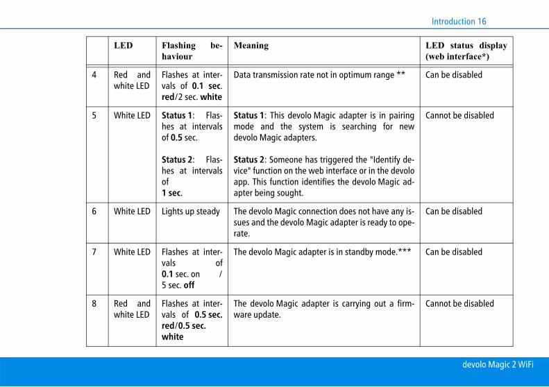
Flashes at inter-vals of 0.1 sec.red/2 sec. white
Data transmission rate not in optimum range ** Can be disabled
5 White LED Status 1: Flas-hes at intervalsof 0.5 sec.
Status 2: Flas-hes at intervalsof1 sec.
Status 1: This devolo Magic adapter is in pairingmode and the system is searching for newdevolo Magic adapters.
Status 2: Someone has triggered the "Identify de-vice" function on the web interface or in the devoloapp. This function identifies the devolo Magic ad-apter being sought.
Cannot be disabled
6 White LED Lights up steady The devolo Magic connection does not have any is-sues and the devolo Magic adapter is ready to ope-rate.
Can be disabled
7 White LED Flashes at inter-vals of0.1 sec. on /5 sec. off
The devolo Magic adapter is in standby mode.*** Can be disabled
8 Red andwhite LED
Flashes at inter-vals of 0.5 sec.red/0.5 sec.white
The devolo Magic adapter is carrying out a firm-ware update.
Cannot be disabled
LED Flashing be-haviour
Meaning LED status display(web interface*)
devolo Magic 2 WiFi
17 Introduction
* Information about the web interface can be found inChapter 4 Network configuration.
** Information on improving the transmission rate can befound in Chapter 5.4 Bandwidth optimization.
***A devolo Magic adapter switches to standby mode af-ter approximately 10 minutes if no active network device(e.g. computer) is connected to the network interface andthe WiFi is switched off. In this mode, the devolo Magic ad-apter cannot be accessed over the electrical wiring. Assoon as the network device (e.g. computer) connected tothe network interface is switched on again, yourdevolo Magic adapter can also be accessed over theelectrical wiring again.
Check whether the adapter is connected to the mainssupply correctly and whether the pairing operationhas been carried out successfully. For more informati-on about this, refer to 3.3 Connecting thedevolo Magic 2 WiFi.
2.3.2 WiFi buttonThis button controls the following functions:
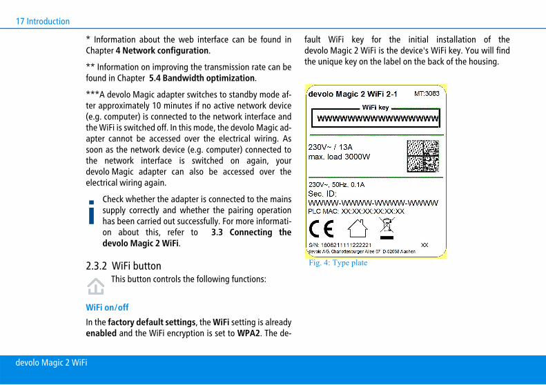
WiFi on/offIn the factory default settings, the WiFi setting is alreadyenabled and the WiFi encryption is set to WPA2. The de-
fault WiFi key for the initial installation of thedevolo Magic 2 WiFi is the device's WiFi key. You will findthe unique key on the label on the back of the housing.
Fig. 4: Type plate
devolo Magic 2 WiFi

Introduction 18
Before the networking procedure, write down the WiFikey of the devolo Magic 2 WiFi. You can find the de-vice's unique key on the label on the rear side of thehousing.
In order to connect the devolo Magic 2 WiFi with yourlaptop, tablet or smartphone later via WiFi, enter thenoted WiFi key as the network security key.
In order to switch WiFi off, press and hold the WiFibutton longer than 3 seconds. In order to switch WiFi back on, briefly tap the WiFibutton.
Connecting WiFi devices via WPS If the device is still on factory defaults, tap the WiFibutton in order to activate WPS.If the WiFi connection was switched off and youwould like to activate WPS, press the WiFi button
twice; once to switch WiFi on, and again to activateWPS.If the WiFi connection is switched on and you wantto copy these settings to another devolo Magic adap-ter, continue reading with the Chapter 4.7.5 ConfigSync.
WPS is one of the encryption standards developed bythe WiFi Alliance. The objective of WPS is to make iteasier to add devices to an existing network. For moredetailed information, refer to Chapter 4.4.6 WiFi Pro-tected Setup (WPS).
2.3.3 Reading the WiFi indicator lightThe integrated WiFi indicator light (LED) shows the statusof the devolo Magic 2 WiFi by illuminating and/or flashing
WiFi-LED Flashing behavior Meaning LED status display (webinterface*)
1 White LED Flashes at intervals of0,1 sec. on /5 sec. off
The devolo Magic adapter is in WPSmode to integrate WiFi-enabled devicesvia WPS.
Cannot be disabled
devolo Magic 2 WiFi

19 Introduction
2.3.4 Reset buttonThe reset button (next to the network jacks) has two diffe-rent functions:
Restart The device restarts if you press the Reset button for lessthan 10 seconds.
Factory default settings
To remove a devolo Magic adapter from yourdevolo Magic network and successfully restore itsentire configuration to the factory defaults, press andhold the reset button longer than 10 seconds.
Keep in mind that all settings that have already beenmade will be lost!
2 White LED Lights up steady WiFi is switched on and active. Can be disabled
3 White LED Off Status 1: Someone has set the "WiFiLED" function in the LED settings on theweb interface or in the devolo app to off.The WiFi LED is switched off and the de-volo magic adapter is still ready for use.
Status 2: Someone has set the "WiFinetwork mode" function in the WiFi net-works settings on the web interface or inthe devolo app to off. The WiFi functionist disabled.
Can be disabled
WiFi-LED Flashing behavior Meaning LED status display (webinterface*)
devolo Magic 2 WiFi
Introduction 20
Wait until the LED flashes white and then disconnectthe devolo Magic adapter from the mains supply.
The devolo Magic adapter has been successfullyremoved from your existing devolo Magic net-work.
2.3.5 Network jacksYou can use the network jacks on the devolo Magic adap-ter to connect it to stationary devices such as computers,game consoles, etc. using a standard network cable.
2.3.6 WiFi antennasThe internal WiFi antennas are for connecting to other net-work devices wirelessly.
2.3.7 Integrated electrical socketAlways use the integrated electrical socket on thedevolo Magic adapter when connecting other consumersto the mains supply. In particular, electronic devices withmains adapter can negatively affect PLC performance.
The integrated mains filter in the devolo Magic adapter fil-ters any such external interference and reduces any impair-ment of PLC performance.
devolo Magic 2 WiFi

21 Initial use
3 Initial useThis chapter tells you everything you need to know to setup and use your devolo Magic 2 WiFi. We describe how toconnect the device and briefly describe the devolo softwarethat comes with it.
3.1 Package contentsPlease ensure that the delivery is complete before begin-ning with the installation of your devolo Magic 2 WiFi:
Single Kit:devolo Magic 2 WiFi Hard copy of installation guidePrinted security flyerSimplified CE declarationOnline documentation
or
Starter Kit:devolo Magic 2 WiFidevolo Magic 2 LAN 1-11 network cable Hard copy of installation guidePrinted security flyerSimplified CE declaration
Online documentation or
Multiroom Kit:2 devolo Magic 2 WiFi1 devolo Magic 2 LAN 1-11 network cable Hard copy of installation guidePrinted security flyerSimplified CE declarationOnline documentation
devolo AG reserves the right to change the package con-tents without prior notice.
3.2 System requirementsOperating systems supported by devolo Cockpitfrom:
Windows 7 (32-bit/64-bit), Ubuntu 13.10 (32-bit/64-bit), Mac (OS X 10.9)
Network connection
devolo Magic 2 WiFi

Initial use 22
Please note that your computer or other device musthave a network card or network adapter with a net-work interface.
To set up a devolo Magic network, you need at leasttwo devolo Magic adapters.
3.3 Connecting the devolo Magic 2 WiFiCAUTION! Damage to the device caused by ambient conditionsOnly use device indoors in dry conditions
In the following sections we describe how to connect thedevolo Magic 2 WiFi and integrate it into a network. Weclarify the exact procedures based on potential networkscenarios.
For the permitted voltage range for operating thedevice and the power consumption, refer to the typeplate on the rear of the device. For additional tech-nical information on our products, refer to the pro-duct area atwww.devolo.com.
3.3.1 Starter Kit – Automatic set-up for a new devolo Magic PLC network
Connect one devolo Magic 2 LAN to your Internetaccess device's network connection (e.g. your Internetrouter).
CAUTION! Tripping hazardLay the network cable in a barrier-free mannerand ensure that the electrical socket and theconnected network devices are easily accessib-le
Plug both devolo Magic adapters into available powersockets within 3 minutes. As soon as the LEDs on bothadapters flash white at regular intervals of 0.5 sec.,they are ready to operate and automatically start theprocess of establishing an encrypted connection toeach other (see Chapter 2.3.1 Reading the PLC indi-cator light).
If the LEDs on both devolo Magic adapters light upin white, then your devolo Magic network hasbeen set up according to your individual specifica-tions and is protected from unauthorised access.
devolo Magic 2 WiFi
23 Initial use
3.3.2 Addition – Expanding an existing PLC net-work by adding another devolo Magic 2 WiFi
Before you can use the devolo Magic 2 WiFi in yourdevolo Magic network, first you have to connect it to yourexisting devolo Magic adapters as a network. This is ac-complished by using a shared password.
Plug the devolo Magic 2 WiFi into an available powersocket. As soon as the LED flashes white at regularintervals of 0.5 seconds, the adapter is ready to ope-rate but not yet integrated into a devolo Magic net-work (see Chapter 2.3.1 Reading the PLC indicatorlight).
Within 3 minutes, press the PLC button on adevolo Magic adapter in your existing devolo Magicnetwork for approximately 1 sec.
If the LEDs light up white on both devolo Magicadapters, the new adapter has been successfullyintegrated into your existing devolo Magic net-work.
For each pairing operation, only one additional adap-ter can be added at a time.
3.3.3 Changing the network passwordA network password can also be changed in the followingways:
Using the web interface of the devolo Magic adapter(see Chapter 4.5 Powerline)
or
Using devolo Cockpit or the devolo app. For moreinformation, refer to the following chapter.
3.3.4 Integrating the devolo Magic 2 WiFi into an existing WiFi network
Establish the WiFi connection with your laptop, tabletor smartphone by entering the previously notedWiFi key as the network security key (see Chapter WiFi on/off).
To ensure that the devolo Magic 2 WiFi has the sameWiFi configuration as your WiFi router, you can applythe WiFi access data at the touch of a button using theWiFi Clone function. This can be enabled in differentways:
Activating WiFi Clone:
Activating WiFi Clone by pressing a button: First pressthe WiFi button with the WiFi icon on the front side ofthe devolo Magic 2 WiFi and then press the WPS but-ton of the WiFi router with the access data you want toapply.
or
devolo Magic 2 WiFi
Initial use 24
Activating WiFi Clone from the web interface. Moreinformation about this function can be found in Chap-ter 4.4.6 WiFi Protected Setup (WPS). More information about the web interface can befound in Chapter 4 Network configuration.
Connecting devices to the WiFi network Establish the WiFi connection with your laptop, tablet
or smartphone by entering the previously notedWiFi key as the network security key (see Chapter WiFi on/off).
3.4 Installation of devolo softwareInstalling devolo Cockpit softwaredevolo Cockpit finds all accessible devolo Magic adaptersin your devolo Magic network, displays information aboutthese devices and encrypts your devolo Magic network in-dividually. You can use the software to navigate to the in-tegrated web interface.
Operating systems supported by devolo Cockpit (Version5.0 or later) from:
Windows 7 (32-bit/64-bit) or later, Ubuntu 13.10 (32-bit/64-bit), Mac (OS X 10.9)
You can find the product manual, software and addi-tional information on devolo Cockpit online atwww.devolo.com/cockpit.
Downloading the devolo AppThe devolo App is devolo's free app also for checking andconfiguring WiFi, Magic and LAN connections for thedevolo Magic adapter (using a smartphone or tablet). Thesmartphone or tablet connects to the devolo Magic adap-ter at home over WiFi.
Download the devolo App to your smartphone ortablet computer from the corresponding store.
The devolo App is placed in your smartphone's ortablet's app list as usual. Tapping on the devolo Appicon brings you to the start menu.
You can find more information about thedevolo App online at www.devolo.com/devolo-app.
3.5 Removing the devolo Magic adapter from a PLC network
To remove a devolo Magic adapter from your network andsuccessfully restore its entire configuration to the factorydefault settings, press the reset button longer than10 seconds. Wait until the LED flashes white and then dis-connect the adapter from the mains supply.
devolo Magic 2 WiFi

25 Initial use
Keep in mind that all settings that have already beenmade will be lost!
To integrate the mains supply into another network, pro-ceed as described in Chapter 3.3.2 Addition – Expandingan existing PLC network by adding anotherdevolo Magic 2 WiFi.
devolo Magic 2 WiFi

Network configuration 26
4 Network configurationThe devolo Magic 2 WiFi has a built-in web interface thatcan be called up using a standard web browser. All settingsfor operating the device can be modified here.
4.1 Calling up the built-in web interfaceYou can access the built-in online web interface for thedevolo Magic 2 WiFi in different ways:
Using the devolo App on your smartphone or tablet,you can access the device's web interface by going tothe devolo App overview page and tapping on thegear/arrow. You can find more information on devolo App in Chap-ter 3.4 Installation of devolo software.
or
Using the Cockpit software under Start All Pro-grams devolo devolo Cockpit, you can get tothe device's web interface by clicking on the corre-sponding tab for the devolo Magic 2 WiFi. Then theprogram determines the current IP address and startsthe configuration in the web browser.
By default, the web interface will open directly. Ho-wever, if an access password has been set via the op-tion System Management, you have to enterthat password first. Read more about this under 4.7System.
4.2 General information about the menuAll menu functions are described in the corresponding in-terface as well as in the associated chapter in the manual.The sequence of the description in the manual follows thestructure of the menu. The figures for the device interfaceserve as examples.
Logging in The web interface is not password protected. Assigning alogin password is mandatory when logging in for the firsttime to prevent unauthorised access by third parties.
Enter your existing password each time you login againand confirm by pressing Log in.
devolo Magic 2 WiFi
27 Network configuration
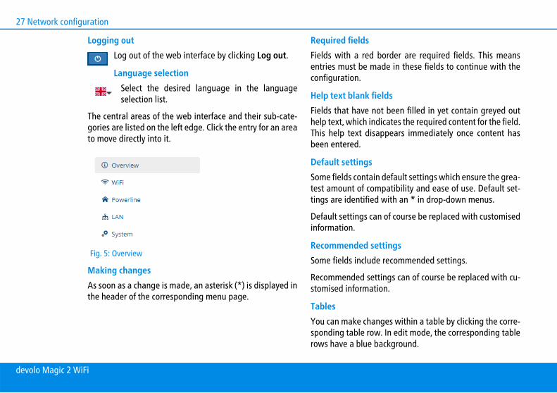
Logging outLog out of the web interface by clicking Log out.
Language selectionSelect the desired language in the languageselection list.
The central areas of the web interface and their sub-cate-gories are listed on the left edge. Click the entry for an areato move directly into it.
Making changesAs soon as a change is made, an asterisk (*) is displayed inthe header of the corresponding menu page.
Required fieldsFields with a red border are required fields. This meansentries must be made in these fields to continue with theconfiguration.
Help text blank fieldsFields that have not been filled in yet contain greyed outhelp text, which indicates the required content for the field.This help text disappears immediately once content hasbeen entered.
Default settingsSome fields contain default settings which ensure the grea-test amount of compatibility and ease of use. Default set-tings are identified with an * in drop-down menus.
Default settings can of course be replaced with customisedinformation.
Recommended settings Some fields include recommended settings.
Recommended settings can of course be replaced with cu-stomised information.
TablesYou can make changes within a table by clicking the corre-sponding table row. In edit mode, the corresponding tablerows have a blue background.
Fig. 5: Overview
devolo Magic 2 WiFi

Network configuration 28
Tables have a filter function to make them easier to workwith. The search function can be limited even further usingspecial characters like ! or " ".
Invalid entriesEntry errors are either highlighted by a red border or errormessages are shown.
ButtonsClick Save to save the settings for the respective web inter-face area.
Click Back or use the Menu path above the buttons to exitthe respective web interface area.
Click the Recycle bin icon to delete an entry.
Click the Arrow icon to refresh a list.
4.3 OverviewThe Overview area shows the status of thedevolo Magic 2 WiFi and the connected LAN, PLC and WiFidevices.
SystemYou can see status information for your device here.
WiFiYou can view status information for a wireless networksuch as frequency channels in use, SSIDs in use andconnected WiFi devices here.
devolo Magic 2 WiFi

29 Network configuration
PowerlineYou can view status information for your devolo Magic net-work and connected devices here.
LANYou can see status information for a cable-based networksuch as protocol information or the connection speed ofboth Ethernet ports, etc. here.
4.4 WiFiMake all changes to your wireless network in the WiFiarea.
devolo Magic 2 WiFi

Network configuration 30
4.4.1 StatusYou can see the current status of your WiFi network confi-guration here. In addition to the connected WiFi stationswith detailed basic information, such as the MAC address,the selected frequency band, the SSID, the transfer ratesand the connection duration, information about whether
you have configured a bridge or a RADIUS server is display-ed. Additionally, you can see the newly added SSIDs withpossible VLAN configurations. You can display detailsabout the respective frequency band using the search func-tion.
Fig. 6: WiFi status
devolo Magic 2 WiFi

31 Network configuration
4.4.2 WiFi networks You can make all necessary changes to your WiFi networkhere.
Fig. 7: WiFi networks
devolo Magic 2 WiFi

Network configuration 32
WiFi network modeThe devolo Magic 2 WiFi supports both the parallel opera-tion of the WiFi frequency bands and their separate use.
The WiFi network mode field lets you define your prefer-red setting by clicking the respective field:
2.4 GHz + 5 GHz – Both frequency bands are used2.4 GHz – Only the 2.4 GHz frequency band is used 5 GHz – Only the 5 GHz frequency band is usedOff – If desired, you can completely switch off the WiFisection of your devolo Magic 2 WiFi here.
Keep in mind that after saving this setting, youwill be disconnected from any existing wire-less connection to the devolo Magic 2 WiFi. Inthis case, configure the device over Ethernet.
Network nameThe network name (SSID) determines the name of yourwireless network. You can see this name when loggingonto the WiFi, allowing you to identify the correct WiFi net-work.
Channel There are 13 channels available in the 2.4 GHz frequencyband. The channels recommended for Europe are channels1, 6 and 11. This ensures the frequency bands of the chan-nels do not overlap and any connection problems are avoi-ded.
There are 11 channels available in the 5 GHz frequencyband.
The channel selection default setting is Automatic. Thedevolo Magic 2 WiFi regularly and automatically executesthe channel selection in this setting. In other words, if thelast connected station logs out, a search for a suitablechannel is carried out immediately. If no stations areconnected, the device automatically selects a channel eve-ry 15 minutes.
It is worth noting that connected devices also have to sup-port the increased frequency band of 5 GHz. From channel52 onward you go into the radar range. When accessingthe device for the first time, a radar detection phase (DFS)starts automatically, during which time thedevolo Magic 2 WiFi cannot be accessed via WiFi.
ChannelsIn the Channel field, you can manually select a 2.4 GHz anda 5 GHz channel. If you are not sure which wireless chan-
devolo Magic 2 WiFi

33 Network configuration
nels are used by nearby devices, select the Automatic op-tion.
Hide SSID:The SSID specifies the name of your wireless network. Youcan see this name when logging onto the WiFi, allowingyou to identify the correct subnet.
If the Hide SSID option is disabled, your network name isvisible. If this option is disabled, potential network usersmust know the exact SSID and enter it manually to be ableto set up a connection.
Some WiFi stations have difficulty connecting to hid-den wireless networks. If the connection to a hiddenSSID poses problems, first try to set up the connecti-on with a visible SSID and only then try to hide it.
SecurityThe WPA2 Personal (WiFi Protected Access) securitystandard is available for securing data transmission in yourwireless network. This method allows for individualisedkeys consisting of letters and numbers and the depictedspecial characters with a length of up to 63 characters.You can simply enter them into the Key field via the key-board.
In addition, the devolo Magic also supports the WPA/WPA2 Enterprise Mode encryption key. As a central au-
thentication and accounting server, a RADIUS server hand-les the registration and management of user informationfor multiple WiFi access points.
4.4.3 Guest networkIf you have friends or acquaintances visiting and you wantto provide them with Internet access but without givingaway the password for your WiFi, you can set up a separateguest account in addition to the main Internet connection.The guest account can have its own network name, time li-mit and WiFi password. This way your visitors can browsethe Internet without having access to your local network.
To set up a guest account, activate the Enable option.
You can also enable or disable the guest account inthe devolo App using the Guest account button.
Fig. 8: WiFi guest network
devolo Magic 2 WiFi

Network configuration 34
Frequency bandIn the Frequency band field, you select the frequencyband mode you are using (see Chapter WiFi network mo-de).
Network nameDefine the name of the guest network in the Networkname field.
KeyYou should also encrypt the guest account to prevent anyo-ne in signal range from intruding into your network and,for example, sharing your Internet connection. The WPA/WPA2 (WiFi Protected Access) security standard is availa-ble for this.
This method allows for individualised keys consisting ofletters and numbers with a length of up to 63 cha-racters. You can simply enter them via the keyboard.
To do so, enter a corresponding number of characters intothe Key field.
QR codeUsing the QR code, you can conveniently set up the connec-tion to the guest network for mobile devices. Scanning theQR code automatically transfers the credentials for theguest network to the respective mobile device.
4.4.4 MeshMeshAll devolo Magic series WiFi adapters offer mesh WiFi,which entails completely new and improved WiFi functi-ons:
Fast roaming ensures that all WiFi clients, such assmartphones and tablets, are always connected to thestrongest WiFi hotspot. This is especially importantwhen people move from room to room with theirmobile devices. In addition, the new air-time fairness feature proces-ses the requests of high-speed WiFi clients at higherpriority. This prevents older devices, which mayrequire more time for a download, from creating WiFibottlenecks. Integrated band steering ensures that all WiFi stati-ons automatically switch to the optimum frequencyband (2.4 and 5 GHz frequency band) in order to usethe best WiFi connection at all times.
In order to turn the mesh functions on, activate the Enableoption.
The mesh function of the devolo Magic 2 WiFi is switchedon by default.
devolo Magic 2 WiFi

35 Network configuration
WiFi CloneWiFi Clone makes it possible to simply copy the WiFi con-figuration data of an existing WiFi access point (e.g. yourWiFi router) to all WiFi access points (Single SSID). Start theprocedure with the Start setup option and then press theWPS button of the device with the WiFi access data (SSIDand WiFi password) to be applied.
Fig. 9: Mesh WiFi
devolo Magic 2 WiFi

Network configuration 36
4.4.5 Schedule controlThe Schedule control area lets you define when and ifyour WiFi is switched on and off.
Fig. 10: WiFi schedule control
devolo Magic 2 WiFi

37 Network configuration
Enabling WiFi schedule controlIn order to be able to use time control, activate the Enableoption.
ConfigurationYou can define multiple time periods during which your wi-reless network is to be enabled for each weekday. Then thetime control automatically switches the wireless networkon or off.
Automatic disconnection If you enable the Automatic disconnection option, the wi-reless network is not switched off until the last station haslogged off.
Manually switching the device on and off (using a but-ton) always has priority over automatic time control.The configured time control then takes effect automa-tically during the next defined time period.
4.4.6 WiFi Protected Setup (WPS)WiFi Protected Setup (WPS) is one of the international en-cryption standards developed by the WiFi Alliance for ea-sily and quickly setting up a secure wireless network. Theencryption keys of the respective WiFi devices are transmit-ted automatically and continuously to the other WiFi de-vice(s) in the wireless network.
devolo Magic 2 WiFi

Network configuration 38
Enabling WPS encryptionIn order to be able to use WPS encryption, activate theEnable option.
The devolo Magic 2 WiFi offers two different variants fortransmitting these encryption keys:
WPS using WPS pushbutton
Start the encryption process on thedevolo Magic 2 WiFi
By pressing the WiFi button on the front side ofthe device or
By pressing the corresponding Start button on theuser interface under WiFi WPS Pushbutton.
Then either press the WPS key of the WiFi device youare adding or enable the WPS mechanism in the WiFisettings of the WiFi device. Now the devices exchangetheir encryption keys and establish a secure WiFiconnection. The WiFi LED on the front panel indicatesthe synchronisation process by flashing.
Fig. 11: WPS
devolo Magic 2 WiFi

39 Network configuration
WPS via PIN
To interconnect WiFi devices in your wireless networksecurely via PIN variant, enter an individualised key onthe web interface under WiFi WPS WPS PIN andstart the encryption process by pressing the correspon-ding Start button.
Open the web interface of the WiFi client to be addedand transmit the PIN selected on thedevolo Magic 2 WiFi. Confirm the encryption processas described there. Now the devices exchange theirencryption keys and establish a secure WiFi connec-tion. The WiFi LED on the front panel indicates the syn-chronisation process by flashing.
Use of the WPS method implies the use of the WPA/WPA2encryption standard. Therefore take note of the followingautomatic settings:
If under WiFi WiFi networks, the No encryptionoption is selected in advance, WPA2 is set automati-cally. The newly generated password is displayedunder WiFi WiFi networks in the Key field. If under WiFi WiFi networks, the WPA/WPA2option is selected in advance, this setting remainswith the previously assigned password.
4.4.7 Neighbour networksThe Neighbour networks area displays visible wirelessnetworks in your surroundings.
devolo Magic 2 WiFi

Network configuration 40
4.5 PowerlineMake all changes to your PLC network in the Powerlinearea.
Fig. 12: Neighbour networks
devolo Magic 2 WiFi

41 Network configuration
Pairing – Establishing a PLC connectionIn order to use a new devolo Magic 2 WiFi in yourdevolo Magic network, first you have to connect it to yourexisting devolo Magic adapters devices as a network. Thisis accomplished by using a shared password. This can beassigned in different ways:
Using dLAN Cockpit or the devolo app (see Chapter3.4 Installation of devolo software), Only using the PLC button (see Chapter 2.3 Pairing –Establishing a PLC connection and 3.3 Connectingthe devolo Magic 2 WiFi) Using the web interface, in the PLC menu; as descri-bed below:
Pairing – Using physical button and on-screen button
First, press the PLC button on a devolo Magic adapterin your existing network.
Then, click Pairing to start the pairing operation. Thismay take some time.
As soon as the new devolo Magic adapter is integratedinto your existing network, it appears in a list of availableand established connections (see Chapter PLC connecti-ons).
Pairing – Using custom password You can also assign your network a custom PLC passwordyou pick yourself. Enter this password for eachdevolo Magic adapter in the Network password field andconfirm your settings by clicking the diskette icon.
Note that the custom password is not assigned to thewhole PLC network automatically. Instead, you must
Fig. 13: Powerline overview
devolo Magic 2 WiFi

Network configuration 42
assign it separately to each of your devolo Magic adap-ters.
Unpairing – Resetting or removing an adapter from a net-work
To remove a devolo Magic adapter from yourdevolo Magic network, click Unpair.
Wait until the LED flashes red and then disconnect thedevolo Magic adapter from the mains supply.
Advanced settingsYou will find the following options in the advanced set-tings:
PLC domain name: Network name
Force node type:
Domain masterAutomatic*: Recommended default settingEnd node
Profiles:
Default mode*: Recommended default settingCompatibility mode: Compatibility mode is a specialmode of the devolo Magic Powerline adapter, whichresolves rare connection issues which can result frominteraction with other technologies such as DSL. This
mode reduces the transmission speed of the Powerlineadapter.
Confirm your settings by clicking the diskette icon.
PLC connectionsThe table lists all available and connected devolo Magicadapters for your network along with displaying the follo-wing details:
Device ID: Device ID (number) of the respectivedevolo Magic adapter in the devolo Magic network
MAC address: MAC address of the respectivedevolo Magic adapter
Send (Mbps): Rate for sending data
Receive (Mbps): Rate for receiving data
Role: Role of the respective devolo Magic adapter on thenetwork
* indicates the local devolo Magic adapter
devolo Magic 2 WiFi
43 Network configuration
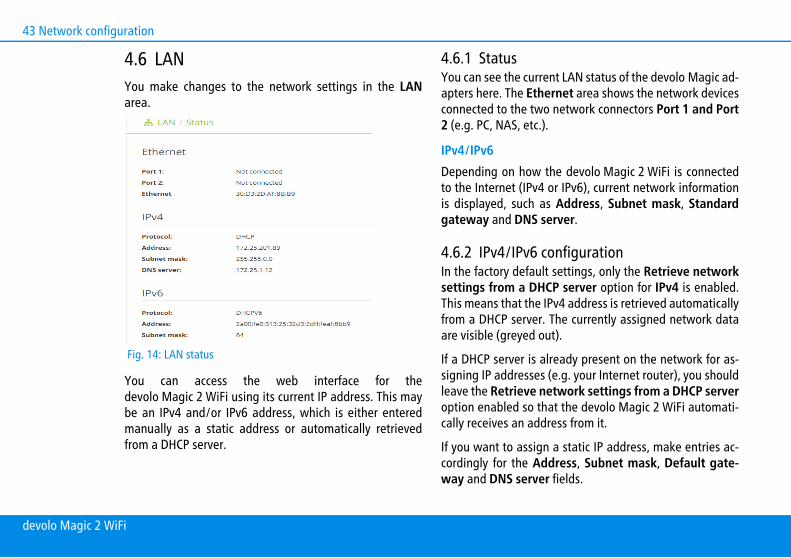
4.6 LANYou make changes to the network settings in the LANarea.
You can access the web interface for thedevolo Magic 2 WiFi using its current IP address. This maybe an IPv4 and/or IPv6 address, which is either enteredmanually as a static address or automatically retrievedfrom a DHCP server.
4.6.1 StatusYou can see the current LAN status of the devolo Magic ad-apters here. The Ethernet area shows the network devicesconnected to the two network connectors Port 1 and Port2 (e.g. PC, NAS, etc.).
IPv4/IPv6Depending on how the devolo Magic 2 WiFi is connectedto the Internet (IPv4 or IPv6), current network informationis displayed, such as Address, Subnet mask, Standardgateway and DNS server.
4.6.2 IPv4/IPv6 configurationIn the factory default settings, only the Retrieve networksettings from a DHCP server option for IPv4 is enabled.This means that the IPv4 address is retrieved automaticallyfrom a DHCP server. The currently assigned network dataare visible (greyed out).
If a DHCP server is already present on the network for as-signing IP addresses (e.g. your Internet router), you shouldleave the Retrieve network settings from a DHCP serveroption enabled so that the devolo Magic 2 WiFi automati-cally receives an address from it.
If you want to assign a static IP address, make entries ac-cordingly for the Address, Subnet mask, Default gate-way and DNS server fields.
Fig. 14: LAN status
devolo Magic 2 WiFi

Network configuration 44
Confirm your settings by clicking the diskette icon.
Then, restart the devolo Magic adapter (see Chapter 4.7.3Configuration) to ensure that your changes take effect.
IPv6 configurationIf you want automatic IP address assignment and there isalready a DHCP server present on the network for as-signing IP addresses (e.g. your Internet router), enable theRetrieve network settings from a DHCP server option toensure that the devolo Magic 2 WiFi automatically recei-ves an address from it.
If you want to assign a static IP address, make entries ac-cordingly for the Address, Subnet mask, Default gate-way and DNS server fields.
Confirm your settings by clicking the diskette icon.
Then, restart the devolo Magic adapter (see Chapter 4.7.3Configuration) to ensure that your changes take effect.
4.7 SystemIn the System area, you can configure the settings for se-curity and other devolo Magic adapter device functions.
4.7.1 Status Here you can view the most important information onthe devolo Magic adapter, including the current date andtime, time zone, MAC address of the adapter, status ofthe WiFi and Powerline LEDs and the two operating but-tons (PLC button and WiFi button).
Fig. 15: System status
devolo Magic 2 WiFi

45 Network configuration
4.7.2 ManagementSystem information lets you enter user-defined names inthe Device name (hostname) and Device location fields.Both pieces of information are particularly helpful if mul-tiple devolo Magic adapters are to be used and identifiedin the network.
Under Change access password, a login password can beset for accessing the web interface.
By default, the built-in web interface of thedevolo Magic 2 WiFi is not protected by a password. Werecommend assigning a password when the installation ofthe devolo Magic 2 WiFi is complete to protect it againsttampering by third parties.
To do so, enter the desired new password twice. Nowthe web interface is protected against unauthorisedaccess with your custom password!
The Powerline standby settings let you enable PowerSa-ve mode for the devolo Magic adapter.
If the Permit PowerSave mode option is enabled, thedevolo Magic 2 WiFi automatically switches to standbymode after approximately 10 minutes if no Ethernetconnection is active, meaning that there is no active net-work device (e.g. computer) connected to the network in-terface.
In this mode, the devolo Magic adapter is not accessibleover the Powerline network. As soon as the network device(e.g. computer) connected to the network interface is swit-ched on again, your devolo Magic adapter can also be ac-cessed over the electrical wiring again.
PowerSave mode is enabled in the devolo Magic adapter'sfactory default condition.
The LED settings let you disable the LED status display ofthe WiFi and Powerline LEDs. The brightness of the WiFiLED can also be reduced so that the devolo Magic adaptercan act as a night light.
An error status is indicated by corresponding flashing be-haviour regardless of this setting (see Chapter 2.3.1 Rea-ding the PLC indicator light).
For information on the LED behaviour of thedevolo Magic adapter in standby mode, refer toChapter 2.3.1 Reading the PLC indicator light.
You can completely disable the operating buttons on thedevolo Magic adapter in order to protect yourself againstpossible changes. Simply disable the Enable PLC buttonor Enable WiFi button option.
The operating buttons are enabled in the devolo Magic ad-apter's factory default condition.
Under Time zone, you can select the current time zone,e.g. Europe/Berlin. The Time server (NTP) option lets you
devolo Magic 2 WiFi

Network configuration 46
specify a time server. A time server is a server on the Inter-net whose task consists of providing the exact time. Mosttime servers are coupled with a radio clock. Select yourtime zone and time server; the devolo Magic 2 WiFi adap-ter automatically switches between standard time andsummer time.
4.7.3 ConfigurationSaving the device configuration To save the enabled configuration to your computer as a fi-le, select the corresponding button in the Management System Save device configuration as file area. Thenenter a storage location and name for the settings file.
Restoring the device configurationAn existing configuration file can be sent to thedevolo Magic 2 WiFi in the System Configuration areaand enabled there. Select a suitable file via the Select file... button and start the operation by clicking the Restorebutton.
Resetting the device configurationThe devolo Magic 2 WiFi is reset to the original factory de-faults in the Management System area with the Resetdevice configuration option.
Doing so causes you to lose your personal WiFi andPLC settings. The last-assigned passwords for thedevolo Magic 2 WiFi are also reset.
For backup purposes, all active configuration settings canbe transmitted to your computer, stored there as a file andreloaded into the devolo Magic 2 WiFi. This function canbe useful for creating a variety of configurations that willlet you quickly and easily set up the device for use in diffe-rent network environments.
Restart deviceIn order to restart the devolo Magic 2 WiFi, select the Re-start button in the System Configuration area.
4.7.4 FirmwareCurrent firmwareThe currently installed firmware of thedevolo Magic 2 WiFi is displayed here.
Download updated firmwareThe firmware of the devolo Magic 2 WiFi includes the soft-ware for operating the device. If necessary, devolo offersnew versions on the Internet as a file download, for examp-le to modify existing functions.
In order to update the firmware, click on the settinghere. The link takes you to the devolo website where
devolo Magic 2 WiFi

47 Network configuration
you can download the appropriate file for thedevolo Magic 2 WiFi to your computer.
Then, navigate to the System Firmware Runupdate area. Click Select file… and select the down-loaded file.
Confirm the update procedure with Run update. Aftera successful update, the devolo Magic 2 WiFi restartsautomatically.
Ensure that the update procedure is not inter-rupted.
4.7.5 Config SyncConfig Sync makes it possible to copy the entire WiFi con-figuration of a devolo Magic 2 WiFi adapter to a newdevolo Magic adapter. This includes the following settings:
WiFi networkGuest networkMesh WiFiTime control and time server settings.
In order to switch Config Sync on, activate the Enable option.
Please note that the WiFi is always switched on or offfor the entire network. Therefore, stop Config Syncfirst on a device that you want to configure or switchseparately.
devolo Magic 2 WiFi

Appendix 48
5 Appendix
5.1 Technical specifications
5.2 Frequency range and transmitting power
Technical specifications in the 5 GHz frequency range
Security 128 Bit AESDevice port 2x RJ45 (Gigabit Ethernet
port)Power consumption Maximum: 12.0 W
Typical: 9.0 WStand-by: 3.4 W
Power supply internal196-250 V AC50 Hz
Temperature (Storage/Operating
-25°C to 70 °C / 0°C to 40°C
Dimensions (in mm,without plug)
152x76x40 (HxWxD)
Ambient conditions 10-90% Humidity, non-con-densing
Certifications CE
Frequency range 5 GHzIEEE standard 802.11 a/h
802.11 n802.11 ac
Indoor frequency range 5150 – 5350 MHzIndoor & outdoor fre-quency range
5150 – 5725 MHz (802.11 a/h, n)5150 – 5350 MHz / 5470 – 5725 MHz (802.11 ac)
Channel bandwidth 20 MHz (802.11 a/h) 20, 40 MHz (802.11 n)20 MHz, 40 MHz, 80 MHz, 160MHz (802.11 ac)
Max. indoor transmissi-on power (EIRP)
200 mW (channel 36 – 64) / 23 dBm
Max. transmitting po-wer
1,000 mW (channel 100 – 140) /30 dBm
devolo Magic 2 WiFi

49 Appendix
Technical specifications in the 2.4-GHz frequency range
5.3 Channels and carrier frequenciesChannels and frequencies in the 5-GHz band
Channels and frequencies in the 2.4 GHz band
Frequency range 2.4 GHzIEEE standard 802.11 b
802.11 g802.11 n
Indoor frequency range –Indoor & outdoor fre-quency range
2399.5 – 2484.5 MHz
Channel bandwidth 20 MHz (802.11 b/g) 20, 40 MHz (802.11 n)
Max. indoor transmissi-on power (EIRP)
100 mW / 20 dBm
Max. transmitting po-wer
100 mW / 20 dBm
Channel Carrier frequency36 5180 MHz40 5200 MHz44 5220 MHz48 5240 MHz
52 5260 MHz56 5280 MHz60 5300 MHz64 5320 MHz100 5500 MHz104 5520 MHz108 5540 MHz112 5560 MHz116 5580 MHz120 5600 MHz124 5620 MHz128 5600 MHz132 5660 MHz136 5680 MHz140 5700 MHz
Channel Carrier frequency1 2412 MHz2 2417 MHz
Channel Carrier frequency
devolo Magic 2 WiFi

Appendix 50
5.4 Bandwidth optimizationTo significantly improve the transmission capacity of thenetwork, we recommend that you comply with the follo-wing "connection rules":
Plug the devolo Magic directly into a wall socket.Avoid using power strips. This may impair the trans-mission of the PLC signals.If there are several sockets in the wall directly next toeach other, they behave like a power strip. Individualsockets are optimal.
3 2422 MHz4 2427 MHz5 2432 MHz6 2437 MHz7 2442 MHz8 2447 MHz9 2452 MHz10 2457 MHz11 2462 MHz12 2467 MHz13 2472 MHz
Channel Carrier frequency
Fig. 16: Bandwith optimization
devolo Magic 2 WiFi
51 Appendix
5.5 Disposal of old devicesTo be used in the countries of the European Union andother European countries with a separate collecting sy-stem:
The icon with crossed-out wastebasket on thedevice means that this product is an electrical orelectronic device that falls within the scope ofapplication of the European Community WEEEDirective. These types of devices may no longerbe disposed of with household waste. Ratherthey can be given to a municipal collection pointfree of charge. Contact your municipal govern-ment to find out the address and hours of the ne-arest collection point.
5.6 Warranty conditionsIf your devolo device is found to be defective during initialinstallation or within the warranty period, please contactthe vendor who sold you the product. The vendor will takecare of the repair or warranty claim for you. The completewarranty conditions can be found at www.devolo.com/warranty.
devolo Magic 2 WiFi

IndexAAdapter equipment 12Authentication and accounting server 33CCE 8CE declaration 8Changing/assigning the network password 14, 23Config Sync 47DDefault WiFi key 17devolo app 24devolo Cockpit 24devolo Magic 10devolo software 24DHCP server 43, 44Disposal of old devices 51Dynamic Frequency Selection 11EExpanding an existing devolo Magic network 14FFactory default settings 19, 24Factory reset 19IIntegrated electrical socket 20Intended use 7
IP address 43IPv4 43LLAN (network connection) 20LED status display 12Login password 26NNetwork connection 20OOperating buttons 45PPackage contents 21Pairing (establishing a PLC connection) 13PLC 11PLC status display 14Powerline 11PowerSave 45PowerSave mode 45Product name concept 11RReset 12, 19SSafety notes 8SSID 33Starting up a new devolo Magic network 13System requirements 21
devolo Magic 2 WiFi

TTime server 45WWiFi antenna 20WiFi key 17WiFi status display 18WPA 34WPA/WPA2 Enterprise Mode 33WPA2 34
devolo Magic 2 WiFi