manual - cleaner. faster. harper. get your green on ... · atm 162 1 thank you for purchasing a...
TRANSCRIPT

ATM 162 1
R
ATM 162 HD
3-2015
OPERATOR’S MANUAL

ATM 1622

ATM 162 1
Thank you for purchasing a Harper ATM 162.
TO THE OWNER OR OPERATOR:
Please take time to read this manual carefully before operating the ATM 162. Each operator should be familiar with all safety precautions along with the operating and service procedures. Knowledge and familiarity will make a difference in how the machine performs.
As with all Harper products, the ATM162 was developed through tough design and testing proce-dures to produce a sturdy, dependable machine. This manual gives assembly and operating infor-mation. Read and understand all instructional materials included with the unit and its components before operating or maintaining the equipment.
An All-Terrain Mower can present hazards to an operator who follows unsafe procedures in either the operation or maintenance of the unit. Therefore, SAFETY WARNINGS are present at certain locations in the text.
SYMBOL: SAFETY WARNING!
MEANING: Failure to understand and obey this warning may result in injury to you or others. Whenever this symbol is used, please pay very close attention to the information presented, and make sure you fully understand. If you do not, contact your dealer or Harper Industries for clarifica-tion.
SAFETY WARNING!
All shields and guards must be in place for proper and safe operation of this equipment. Where they are shown removed in this manual, it is for purposes of illustration and instruc-tion only. Do not operate this equipment unless all shields and guards are in place.
© 2015 Harper Industries, Inc.The Harper and DewEze names and the ATM logo are registered trademarks of Harper Industries, Inc. All other brand and product
names are trademarks or registered trademarks of their respective companies.
CALIFORNIAProposition 65 Warning
Diesel engine exhaust and some of its constituents are known to the State of California to cause cancer, birth defects, and other reproductive harm.
ATM 1622
LIMITED WARRANTY
The Harper ATM 162 is warranted against defects in workmanship and materi-als for a period of one (1) year from the original date of retail purchase to the origi-nal purchaser.
Harper Industries will repair or replace, at its own option, any part that evalu-ation shows to be defective. Warranty is limited to parts, labor and ground freight delivery of replacement parts. The user will pay freight charges for expedited or-ders of replacement parts and/or parts submitted for warranty evaluation. No prod-uct or part may be returned for warranty evaluation without prior approval.
This warranty does not apply to parts subjected to misuse, abuse, alteration, improper or inadequate maintenance, or normal wear (including belts, blades and tires).
Diesel engines are not covered under this warranty. Refer to manufacturer’s warranty for specific warranty information. Harper Industries makes no warranty with respect to trade accessories. They are subject to the warranties of the manu-facturer.
RECORDS
Date of Purchase ______ / ______ / ______
Dealer’s Name _________________________________ Dealer’s Phone _________________________________ Serial Number Machine __________________________ Serial Number Engine ___________________________

ATM 162 3
Table of ContentsOPERATOR SECTIONTo the Owner or Operator...............................................Warranty Statement........................................................Table of Contents............................................................Specifications..................................................................Introduction Guidelines for Safe Operation.......................... Slope Capability................................................ Parameters for Grass Cutting..........................General Safety Guidelines Equipment & Controls...................................... Guards & Shields............................................. Replacement Parts........................................... Before Operation.............................................. During Operation.............................................. After Operation................................................. While Traveling Roadways............................... Safety Decals................................................... Hydraulics........................................................ Diesel Fuel........................................................Control Identification Dash Controls.................................................. Deck Valve....................................................... Turn Signal Lever............................................. Joystick Controls............................................. Controls on Side Panel.................................... Controls Above Windshield ............................. Park Brake...................................................... Park Brake Release........................................ Cab Lift Switch................................................ Hydrostat Bypass Valve.................................. Sensors........................................................... Seat Adjustments............................................. Heater Valve.................................................... Climate Control................................................ Air Conditioner.................................................Operation Before Starting Unit......................................... Before Cutting Grass....................................... While Cutting Grass........................................ Stopping Operation......................................... Traveling over Roadways................................Adjustments Cutting Height................................................. Automatic Leveling..........................................Maintenance Hydraulic System............................................ Grease Locations............................................ Safety Brace.................................................... Hood................................................................ Air Cleaner....................................................... Cooling Systems.............................................. Engine Oil........................................................ Fuel Filter......................................................... Fuel Shut-off.................................................... Fuse Panel...................................................... Relay Panel.....................................................Standard Torque Chart.................................................Maintenance Schedule.................................................
1234
556
6667777778
91010101111111112121313141414
1515151515
1616
18191920202021212122222324

ATM 1624
SpecificationsEngine QSB3.3 (Tier 3) Cummins diesel - 99 HP, 3.3L (200 cu. in.),
turbocharged, liquid cooled 220 ft-lb torque, fully pressurizedlubrication system and 5.5 gallon cooling system.
Electrical 12 volt, 95 amp automotive typeCapacities • Hydraulic oil – 50 U.S. gallons in reservoir, 70 gal. in system
• Diesel fuel – 30 U.S. gallons in tankGround Drive Sauer hydrostatic transmission with joystick control in cab, three Po-
clain wheel motors (6631 ft-lbs torque)Park Break Mechanically applied, hydraulically released with manual overrideSteering Steering wheel with power steeringMain Frame Rectangular tubeDrive Tires Three drive tires with all-terrain tread (320/80 R18)Gauge Wheels Four 16.5 x 6.5 x 8, foam filledLeveling Self-leveling up to 28° slope with manual override switchSeat Adjustable seat with arm rests and seat beltGauges/Lights Tachometer, engine oil pressure, water temp., fuel gauge, volt &
hour meters, deck motor, hydraulic reservoir temp., propulsion looptemp., hydraulic filter plugging indicator, load indicator
Blade Drive Three direct hydraulic motors with load sense pumpMower Blades Swinging bladesMower Deck 7-gauge reinforced steel, three floating decks with rear discharge,
hydraulic deck lift and outside wing foldGround Speed 0 to 12 mphCutting Height Adjustable from 4.5” to 7.5”Cutting Width 144 inchesTransport Width 102 inchesOverall Dimensions 178” length, 150” width (deck wings down), 137” height (with cab)Weight 9,500 lbs. (wet)Standard Equipment Cab with ROPS, A/C, heater, AM/FM radio, CD playerWarranty 1 year, unlimited hours
NOTE: Following publication of this manual, certain changes in standard equipment and options may have occurred which would not be included in these pages. Your Harper dealer is the best source for up-to-date information.

ATM 162 5
Introduction
The objective of Harper Industries in design-ing the ATM 162 was to create a mowing ma-chine that could function safely and comfort-ably on slopes and inclines. The result is an All-Terrain Mower that will automatically adjust itself to keep the operator in a vertical position on all slopes up to 28 degrees. Driving with an automatic leveling device will be a new and different experience. After sev-eral minutes of driving, the smooth control and sturdy feel will become comfortable to you. The security of always sitting upright and the feel of powerful, positive traction will give you confidence and comfort in most mowing situ-ations. However, we urge EXTREME CAU-TION lest your confidence in these features get you into trouble.
REMEMBER: The features of the ATM 162 cannot replace good common sense.
Guidelines for Safe Operation
1) Read the safety decals located at vari- ous places on the machine.2) Use the steps and walkway to access the cab. Do not walk over decks.3) Take time to get used to the handling characteristics of the unit.4) Always look before backing up.5) Slow down over rough terrain. 6) Make wide, slow turns on steep in- clines.7) Never attempt to operate the machine while under influence.8) Never attempt to operate the machine when it is not functioning properly.9) Approach any slope with extreme cau- tion. (See Slope Capability.) 10) If it is necessary to park the mower on a hill, be sure to USE THE PARK BRAKE AND CHOCK THE WHEELS!11) Wear protective eyewear and cloth ing while operating or maintaining the mower.
Beacon Lights
Deck Wing
Deck
Hood
HeadLights
Cab
Air Conditioner
Hydraulic OilReservoir
Oil Level Sight Gauge/Thermometer
ATM 1626
12) Do not allow children or animals near the machine or in the area being mowed. 13) Always avoid mowing over debris that could be projected from the mower discharge.14) For best results, operate the mower engine at full throttle. This will allow the blades to rotate at optimum speed, and the leveling device to be the most responsive. 15) Slow down when turning. Fast turns may not allow the leveling system to respond quickly enough to keep the unit vertical. 16) Before dismounting, turn off blades and place hydrostat control in neutral. Turn off engine and remove key. 17) Engine governor settings are pre set and should not be changed; any change can damage moving parts and void warranty.
SAFETY WARNING! The automatic leveling will not work if the steering wheel is held against the stop dur-ing extreme left or right turns. Make wide, slow turns on steep inclines, and only turn uphill when driving on slopes.
Slope CapabilityThe ATM 162 is manufactured with the abil-ity to keep the operator and engine vertical on slopes up to 28 degrees. However, as with all hillside mowers, the degree of slope that the unit can safely traverse is dependent on a number of factors: environmental conditions (e.g.: wet or dry), type of the terrain (e.g.: sand or clay), machine condition (well or poorly maintained), and operator skill (novice or ex-perienced). Therefore, the operator is the final judge as to whether any slope can be safely negotiated.
SAFETY WARNING! Inspect area to be mowed for obstacles, environmental conditions and terrain type before beginning operation.
Parameters for Grass CuttingThe principal objective when mowing is to achieve the highest quality cut with the great-est efficiency. However, there are many envi-ronmental conditions that work to diminish the capacity of the machine to achieve this goal. The variables include: type, density, length and moisture content of the vegetation. When determining the proper way to cut grass, each of these variables must be given serious con-sideration.
The operator is able to make adjustments to the machine that will increase the cutting ef-ficiency. These adjustments include: deck height, ground speed and blade sharpness. Blades should be sharpened and/or replaced on a regular basis to improve cut and reduce resistance. Deck height and ground speed should be determined based on environmen-tal conditions.
The highest quality of cut can usually be achieved by removing only 1/3 of the plant when the initial length is 9” or less. Mowing taller or extremely dense grass while using a low deck height setting will cause material to build up under the deck faster than it can be ejected. This build up can create enough resistance to slow the tip speed of the blade, causing a drastic reduction in cut quality. This may occur without noticeable change in en-gine speed.
Certain situations may require two passes with different deck heights and/or a slower ground speed to achieve the desired cut qual-ity. When a better-looking final cut is desired, making two passes in tall grass can dramati-cally improve the quality of the cut. The deck should be raised on the first cut to near maxi-

ATM 162 7
mum height to allow grass to escape freely. The deck should then be lowered to the de-sired height to make the final cut.
SAFETY WARNING! Never attempt to service blades or adjust deck assembly with key in ignition.
Equipment & Controls • Before operating this equipment, read and understand the Operator’s Manual. • Altering the unit in any way that ad- versely affects its safe operation, per- formance or durability will void the wa- rranty and may cause hazardous con- ditions. • Know the location and function of all controls and how to stop the equip- ment quickly in an emergency before you operate the unit. • Keep all bolts, screws and fittings tight to ensure safe operation of equipment. Guards & Shields • Keep all safety devices in place and in good operating condition. • Replace all worn, damaged, unusable, missing or lost safety shields and guards before operating unit.
Replacement Parts• Use genuine factory parts or parts with equivalent characteristics including: type, strength and material. • Replace locknuts and locking screws if they cannot be tightened without considerable resistance for several turns before they are completely tight. • If hardware is not secure, or if fasten- ers are over-tightened, equipment fail- ure may result posing possible safety hazards. • Use proper torque specifications for all fasteners when they are replaced.
SAFETY WARNING! Failure to use genuine factory parts may result in voidance of warranty, product malfunction or possible injury.
Before Operation • Before starting the machine, visually inspect all nuts, bolts and other fasteners to see that they are properly secured. • Nuts, bolts, screws and fittings should be inspected after the first hour of op- eration and every 8 to 10 hours of operation there after for proper tight- ness. • Make sure all belts and hoses are in good condition. Replace if necessary. • Tire pressure should be at the manu- facturer’s specs and equal in all three drive tires. • Clear all foreign objects such as rocks, bottles or other hard materials that lay in the area to be mowed. • Use steps to access cab. Do not walk across decks.
During Operation• While operating the equipment, make sure that no foreign objects such as rocks, bottles or other hard materials pass under the deck of the mower. • If an object should strike the blades causing an unusual noise or vibration, shut the engine off immediately and allow it to come to a complete stop. Take all prescribed safety precautions and do the following: 1) Inspect for damage. 2) Check for debris, wire, or string around the blades 2) Repair or replace damaged parts. 3) Tighten any loose fasteners or parts. • Keep the engine area clean and free of debris and other accumulations.
General Safety Guidelines

ATM 1628
After Operation• Park in a level area, return hydrostat control to the neutral position and turn engine off (park brake will set).• Remove key from ignition, lock doors and store key in a safe location.
While Traveling Roadway• Raise deck, add spacers, and lock deck wings with safety chains before entering roadways.• Turn on hazard lights and use turn sig- nal when making turns. Use strobe to give additional alert to others when traveling or working alongside road ways.
Safety Decals • If safety related or instructional decals become illegible or are removed, re- place them immediately. • If parts are replaced, make sure all safety related or instructional decals are present before the equipment is operated again. • New decals may be obtained from your local Harper Dealer.
Hydraulics
To prevent serious injury or death:• Relieve pressure on system before repairing, adjusting or disconnecting any hydraulic hose or fitting.• Wear proper hand and eye protection when searching for leaks. • Use wood or cardboard instead of hands when looking for leaks.• Keep all hoses, fittings and compo- nents in good operating condition.• Do not use any type of heat or flame (welding, soldering, cutting torch, etc.) near pressurized hydraulic lines.
SAFETY WARNING! HIGH-PRESSURE FLUID HAZARD!Escaping fluid under pressure can pen-etrate skin causing serious injury or death.
SAFETY WARNING! Always keep a fire extinguisher with the ATM 162 during operation and service. Diesel Fuel • Always use an approved container for transporting diesel fuel. • Do not allow open flames or sparks while performing maintenance or refu- eling. • Never remove fuel tank cap or add fuel when engine is running or while it is hot.• Only use ultra low sulfer diesel.• Never fill fuel tank indoors. Fumes are heavy and will sink to the lowest point, collect and become hazardous. • Wipe up spilled fuel immediately.• Do not store fuel in a room with an ap- pliance that has a gas pilot or electri- cal switch that may cause sparks. • Always store diesel outside in a safe- ty can (a can with flame arrestor and pressure relief valve in pour spout). • Never store the equipment with fuel in the tank inside a building where fumes may reach an open flame or spark.• Allow the engine to cool before storing in any enclosure. • Be certain to provide adequate ventila- tion if an engine must be run indoors exhaust fumes are dangerous.
SAFETY WARNING! Diesel fuel is extremely flammable and can be highly explosive.
SAFETY WARNING! To prevent possible eye injury, always wear SAFETY GLASSES while operating or ser-vicing the equipment.
ATM 162 9
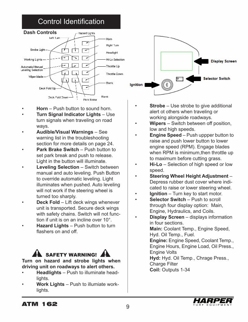
Dash Controls
• Horn – Push button to sound horn.• Turn Signal Indicator Lights – Use turn signals when traveling on road ways. • Audible/Visual Warnings – See warning list in the troubleshooting section for more details on page 24.• Park Brake Switch – Push button to set park break and push to release. Light in the button will illuminate.• Leveling Selection – Switch between manual and auto leveling. Push Button to override automatic leveling. Light illuminates when pushed. Auto leveling will not work if the steering wheel is turned too sharply.• Deck Fold – Lift deck wings whenever unit is transported. Secure deck wings with safety chains. Switch will not func- tion if unit is on an incline over 10°.• Hazard Lights – Push button to turn flashers on and off.
SAFETY WARNING! Turn on hazard and strobe lights when driving unit on roadways to alert others. • Headlights – Push to illuminate head- lights.• Work Lights – Push to illumiate work- lights.
• Strobe – Use strobe to give additional alert ot others when traveling or working alongside roadways. • Wipers – Switch between off position, low and high speeds.• Engine Speed – Push uppper button to raise and push lower button to lower engine speed (RPM). Engage blades when RPM is minimum,then throttle up to maximum before cutting grass.• Hi-Lo – Selection of high speed or low speed.• Steering Wheel Height Adjustment – Depress rubber dust cover where indi- cated to raise or lower steering wheel. • Ignition – Turn key to start motor.• Selector Switch – Push to scroll through four display option: Main, Engine, Hydraulics, and Coils.• Display Screen – displays information in four sections. Main: Coolant Temp., Engine Speed, Hyd. Oil Temp., Fuel. Engine: Engine Speed, Coolant Temp., Engine Hours, Engine Load, Oil Press., Engine Volts Hyd: Hyd. Oil Temp., Chrage Press., Charge Filter Coil: Outputs 1-34
Control Identification

ATM 16210
Deck Valve
• Deck Valve – Controls oil flow to the deck motors and is turned on and off by the blade switch. • Counterbalance – Controls spin-down time of blades (five to seven seconds). • Actuator – When the blade switch is turned off the actuator on the deck valve requires two to three seconds to shut down completely.
SAFETY WARNING! If engine dies or power is cut off to blade switch unexpectedly, restart engine with caution and make sure deck valve has enough time to turn off blades before at-tempting any type of service.
Dash Indicator Lights
• Wait to Start – Wait for the light to turn off before turning key for engine ignition• Check Engine – Check engine for broken parts, and perform routine maintainence• Stop Engine – Stop vehicle, turn off engine, and inspect for broken parts immediately• System Fault – Electrical fault or failure, check system for failed parts. check display screen for details
Joystick Controls
• Manual Leveling – Use buttons to level unit manually left or right.• Deck Lift – Use buttons to raise and lower deck assembly. Make sure both doors are closed when deck wings are folded and lifted to highest position.• Hydrostat Control – Push hydrostat control forward or pull backward slowly to control movement of unit. Return to neutral to stop. Avoid abrupt stops. Unit will not start if hydrostat control is not in neutral position.• Hydrostat Range – Operate mower in low range and switch to high range for transport.• Blade Switch – Lift plastic cover and toggle switch to turn on the blades. Blades will not engage if operator is not in seat or deck wings are raised more than 20º• Accessory Plug – 12-volt accessories may be operated from plug.
SAFETY WARNING!
The automatic leveling will not work if the steering wheel is turned too sharply to the right or left. Make wide, slow turns on steep inclines uphill only.
ATM 162 11
Controls above Windshield
• Radio / CD Player – The clock and memory of the radio are protected by a fuse in lower fire-wall cavity
SAFETY WARNING! Turn on hazard and strobe lights when driving unit on roadways to alert others. Park Brake• The Park Brake is applied mechani- cally by a spring when engine is turned off. Hydraulic pressure releases the park brake when engine is turned on. • The brake switch may be used to set the Park Brake while the engine is run- ning. When the brake is set, the indi- cator light will illuminate.
• There is no need to manually apply park brake when unit is turned off properly (no malfunction). Park brake is hydraulically turned off when engine is running.
PRECAUTION• If park brake is turned on manually with brake switch while machine is moving, turn it off before engaging hy- drostat. Failure to do so may seriously damage wheel motors.
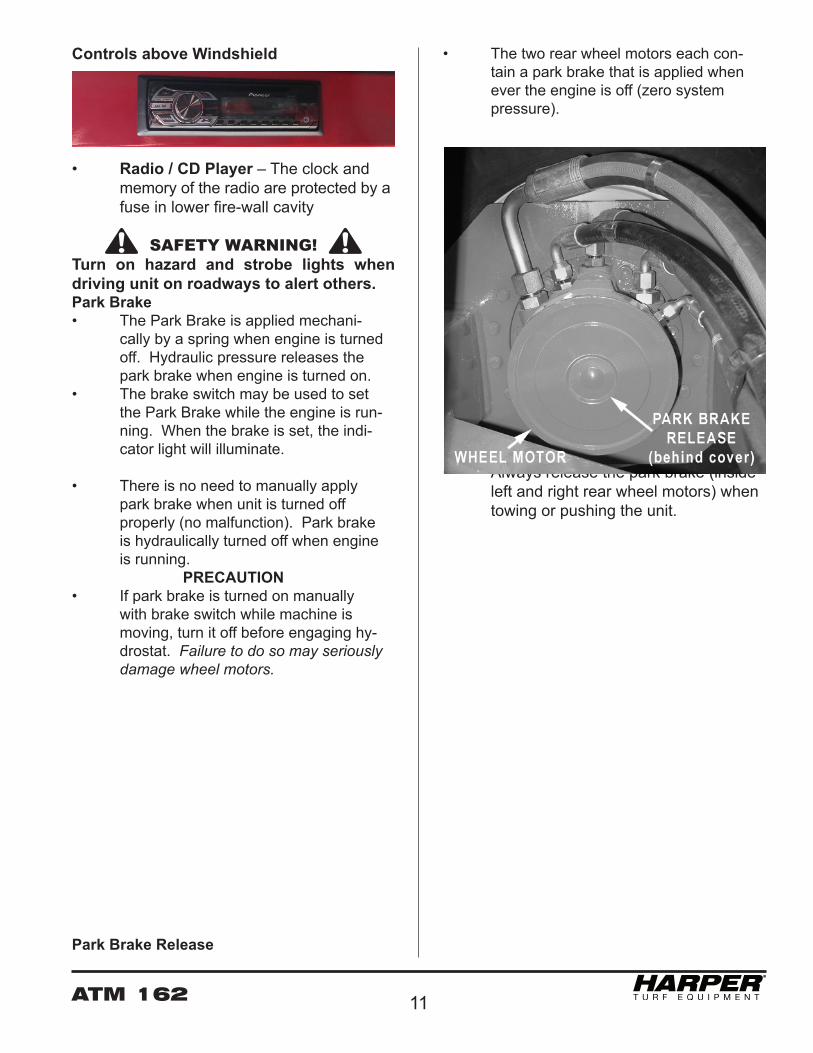
Park Brake Release
• The two rear wheel motors each con- tain a park brake that is applied when ever the engine is off (zero system pressure).
• Always release the park brake (inside left and right rear wheel motors) when towing or pushing the unit.
ATM 16212
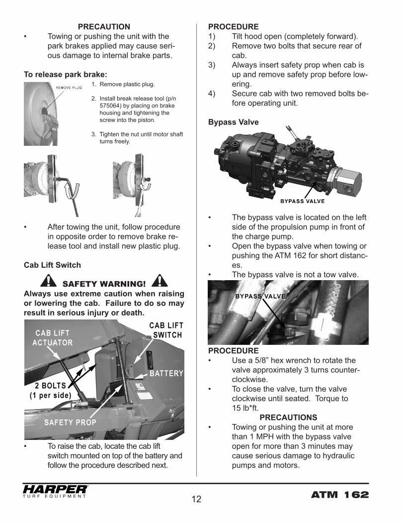
PRECAUTION• Towing or pushing the unit with the park brakes applied may cause seri- ous damage to internal brake parts.
To release park brake:
• After towing the unit, follow procedure in opposite order to remove brake re- lease tool and install new plastic plug.
Cab Lift Switch
SAFETY WARNING! Always use extreme caution when raising or lowering the cab. Failure to do so may result in serious injury or death.
• To raise the cab, locate the cab lift switch mounted on top of the battery and follow the procedure described next.
PROCEDURE1) Tilt hood open (completely forward).2) Remove two bolts that secure rear of cab.3) Always insert safety prop when cab is up and remove safety prop before low- ering.4) Secure cab with two removed bolts be- fore operating unit.
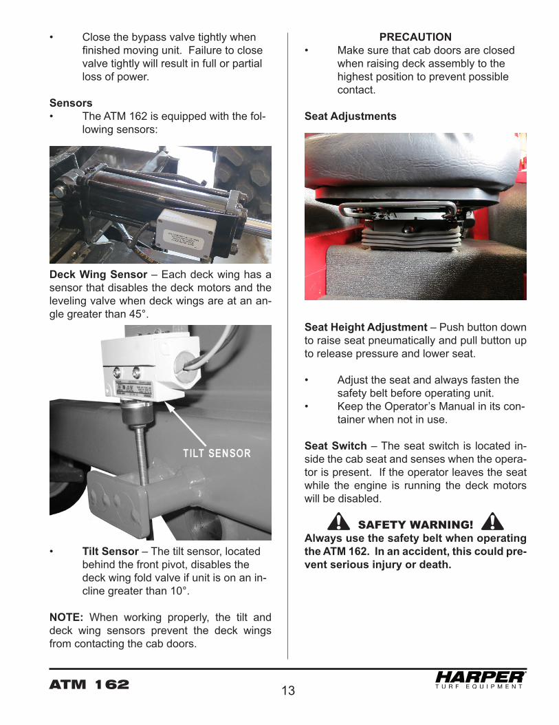
Bypass Valve
• The bypass valve is located on the left side of the propulsion pump in front of the charge pump.• Open the bypass valve when towing or pushing the ATM 162 for short distanc- es. • The bypass valve is not a tow valve.
PROCEDURE• Use a 5/8” hex wrench to rotate the valve approximately 3 turns counter- clockwise.• To close the valve, turn the valve clockwise until seated. Torque to 15 lb*ft.
PRECAUTIONS• Towing or pushing the unit at more than 1 MPH with the bypass valve open for more than 3 minutes may cause serious damage to hydraulic pumps and motors.
1. Remove plastic plug.
2. Install break release tool (p/n 575064) by placing on brake housing and tightening the screw into the piston.
3. Tighten the nut until motor shaft turns freely.
ATM 162 13
• Close the bypass valve tightly when finished moving unit. Failure to close valve tightly will result in full or partial loss of power.
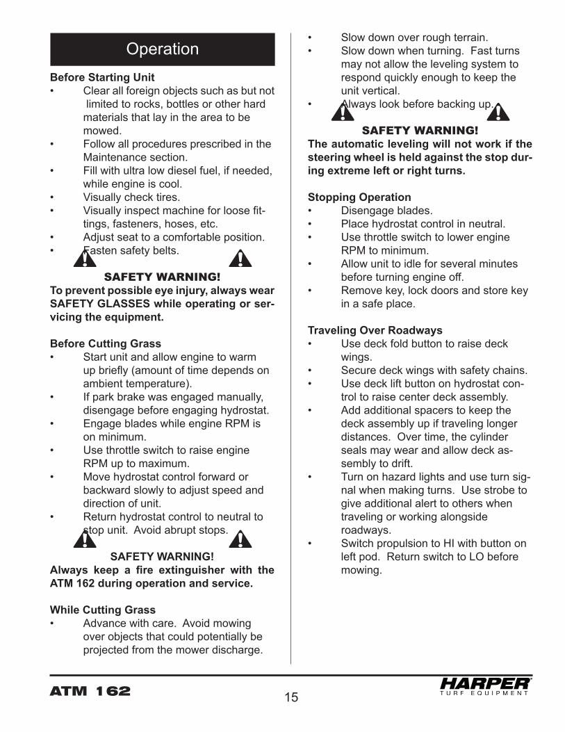
Sensors• The ATM 162 is equipped with the fol- lowing sensors:
Deck Wing Sensor – Each deck wing has a sensor that disables the deck motors and the leveling valve when deck wings are at an an-gle greater than 45°.
• Tilt Sensor – The tilt sensor, located behind the front pivot, disables the deck wing fold valve if unit is on an in- cline greater than 10°.
NOTE: When working properly, the tilt and deck wing sensors prevent the deck wings from contacting the cab doors.
PRECAUTION• Make sure that cab doors are closed when raising deck assembly to the highest position to prevent possible contact.
Seat Adjustments
Seat Height Adjustment – Push button down to raise seat pneumatically and pull button up to release pressure and lower seat. • Adjust the seat and always fasten the safety belt before operating unit.• Keep the Operator’s Manual in its con- tainer when not in use.
Seat Switch – The seat switch is located in-side the cab seat and senses when the opera-tor is present. If the operator leaves the seat while the engine is running the deck motors will be disabled.
SAFETY WARNING!Always use the safety belt when operating the ATM 162. In an accident, this could pre-vent serious injury or death.

ATM 16214
Air Conditioner
• The air conditioner is located on the roof of the cab.• Clean the condenser coils daily, or as required (if performance diminishes).
• Switches for the air conditioner and fan are located on the ceiling of the cab.• Clean out the filter of the air inlet peri- odically.
• Make sure the condensate drain tubes flow freely.
ATM 162 15
Before Starting Unit• Clear all foreign objects such as but not limited to rocks, bottles or other hard materials that lay in the area to be mowed.• Follow all procedures prescribed in the Maintenance section. • Fill with ultra low diesel fuel, if needed, while engine is cool.• Visually check tires.• Visually inspect machine for loose fit- tings, fasteners, hoses, etc.• Adjust seat to a comfortable position.• Fasten safety belts.
SAFETY WARNING! To prevent possible eye injury, always wear SAFETY GLASSES while operating or ser-vicing the equipment.
Before Cutting Grass• Start unit and allow engine to warm up briefly (amount of time depends on ambient temperature).• If park brake was engaged manually, disengage before engaging hydrostat. • Engage blades while engine RPM is on minimum.• Use throttle switch to raise engine RPM up to maximum.• Move hydrostat control forward or backward slowly to adjust speed and direction of unit. • Return hydrostat control to neutral to stop unit. Avoid abrupt stops.
SAFETY WARNING! Always keep a fire extinguisher with the ATM 162 during operation and service.
While Cutting Grass• Advance with care. Avoid mowing over objects that could potentially be projected from the mower discharge.
• Slow down over rough terrain. • Slow down when turning. Fast turns may not allow the leveling system to respond quickly enough to keep the unit vertical. • Always look before backing up.
SAFETY WARNING! The automatic leveling will not work if the steering wheel is held against the stop dur-ing extreme left or right turns.
Stopping Operation• Disengage blades.• Place hydrostat control in neutral. • Use throttle switch to lower engine RPM to minimum.• Allow unit to idle for several minutes before turning engine off.• Remove key, lock doors and store key in a safe place.
Traveling Over Roadways• Use deck fold button to raise deck wings.• Secure deck wings with safety chains.• Use deck lift button on hydrostat con- trol to raise center deck assembly.• Add additional spacers to keep the deck assembly up if traveling longer distances. Over time, the cylinder seals may wear and allow deck as- sembly to drift.• Turn on hazard lights and use turn sig- nal when making turns. Use strobe to give additional alert to others when traveling or working alongside roadways.• Switch propulsion to HI with button on left pod. Return switch to LO before mowing.
Operation

ATM 16216
Cutting Height• The cutting height can be adjusted from a minimum of 4½“ to a maximum of 7½“.• There are front and rear deck lift cylinders on both sides of the unit. All four cylinders are the same size and move uniformly.
• The front of the deck assembly is ap- proximately ¼” lower than the rear to promote greater cutting efficiency.
PROCEDURE• To set the cutting height, raise the deck assembly with the deck lift button.• Turn off the engine and remove the key while placing spacers on cylinders.• The unit comes with 12 – 1” and 8 – ½” spacers used to set cutting height.
• Place an equal number of spacers on each of the deck lift cylinders.• Lower the deck assembly against the spacers.• Note: ½” of travel on the deck lift cylin- der corresponds to approximately 1” of lift.
SAFETY WARNING! Use extreme caution when setting the cut-ting height. Make sure engine is off and key is removed. Failure to do so may re-sult in severe injury or death.
Automatic Leveling• The automatic leveling may be turned on and off with the switch on the dash.• The automatic leveling may not return the unit to a perfect vertical position af- ter every turn. Use the manual level- ing buttons on the joystick to adjust the unit to a comfortable position. • Two mercury switches keep the cab vertical when the automatic leveling is on.• The mercury switches are preset from the factory and should not require im- mediate adjustment.
Adjustments
ATM 162 17
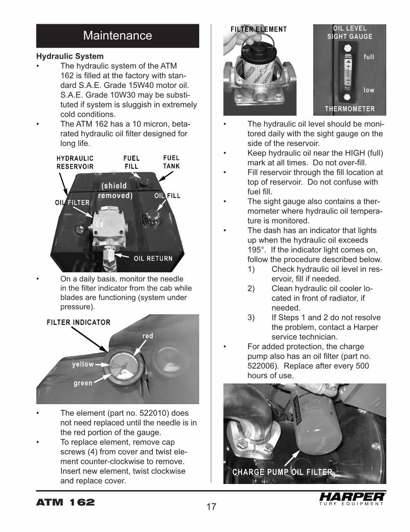
• The hydraulic oil level should be moni- tored daily with the sight gauge on the side of the reservoir.• Keep hydraulic oil near the HIGH (full) mark at all times. Do not over-fill.• Fill reservoir through the fill location at top of reservoir. Do not confuse with fuel fill.• The sight gauge also contains a ther- mometer where hydraulic oil tempera- ture is monitored. • The dash has an indicator that lights up when the hydraulic oil exceeds 195°. If the indicator light comes on, follow the procedure described below. 1) Check hydraulic oil level in res- ervoir, fill if needed. 2) Clean hydraulic oil cooler lo- cated in front of radiator, if needed. 3) If Steps 1 and 2 do not resolve the problem, contact a Harper service technician.• For added protection, the charge pump also has an oil filter (part no. 522006). Replace after every 500 hours of use.
Hydraulic System• The hydraulic system of the ATM 162 is filled at the factory with stan- dard S.A.E. Grade 15W40 motor oil. S.A.E. Grade 10W30 may be substi- tuted if system is sluggish in extremely cold conditions.• The ATM 162 has a 10 micron, beta- rated hydraulic oil filter designed for long life.
• On a daily basis, monitor the needle in the filter indicator from the cab while blades are functioning (system under pressure).
• The element (part no. 522010) does not need replaced until the needle is in the red portion of the gauge.• To replace element, remove cap screws (4) from cover and twist ele- ment counter-clockwise to remove. Insert new element, twist clockwise and replace cover.
Maintenance

ATM 16218
steering assembly(3 - see photo)
rear deck lift(1 per side)
rear pivot (2)
wing hinges (2 per side)
front deck lift hinges (2 per side)
front pivot (1)
Safety Brace
PRECAUTIONS• Secure the safety brace on left rear leveling cylinder with lynch pins (2) when maintenance is done. We strongly recommend that if the unit is parked for long periods, 24+ hours, to install safety brace.• Always remove the safety brace before operating the unit.
Grease Zerk Locations
PROCEDURE1) Park on level ground and set park brake.2) Lower decks to the ground.3) Turn off engine and remove key.4) Give 2 or 3 shots of grease after every 10 hours of use.
SAFETY WARNING! CRUSHING DANGER! Use extreme cau-tion while working on or beneath mower. Always use leveling cylinder safety brace.
ATM 162 19
HOOD LATCH KNOB
RADIATOR CLEANOUT DOOR HANDLE
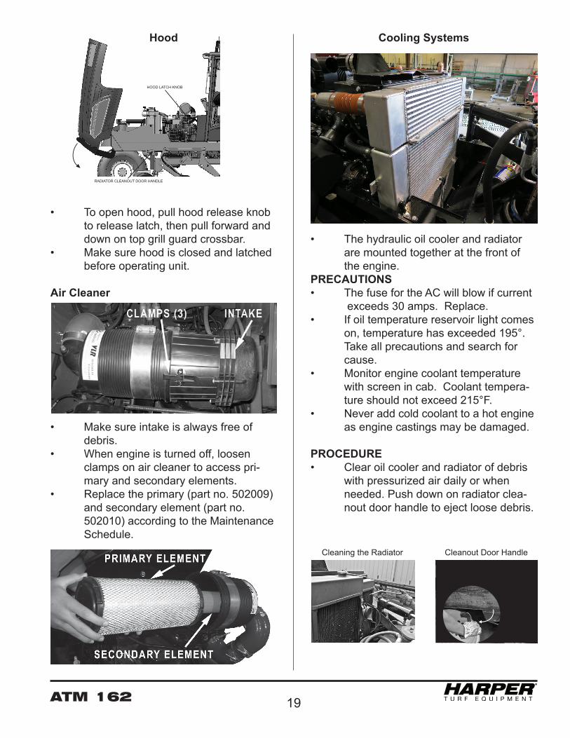
HOOD Cooling Systems
• The hydraulic oil cooler and radiator are mounted together at the front of the engine.PRECAUTIONS• The fuse for the AC will blow if current exceeds 30 amps. Replace.• If oil temperature reservoir light comes on, temperature has exceeded 195°. Take all precautions and search for cause.• Monitor engine coolant temperature with screen in cab. Coolant tempera- ture should not exceed 215°F.• Never add cold coolant to a hot engine as engine castings may be damaged.
PROCEDURE• Clear oil cooler and radiator of debris with pressurized air daily or when needed. Push down on radiator clea- nout door handle to eject loose debris.
Hood
• To open hood, pull hood release knob to release latch, then pull forward and down on top grill guard crossbar.• Make sure hood is closed and latched before operating unit.
Air Cleaner
• Make sure intake is always free of debris.• When engine is turned off, loosen clamps on air cleaner to access pri- mary and secondary elements.• Replace the primary (part no. 502009) and secondary element (part no. 502010) according to the Maintenance Schedule. Cleaning the Radiator Cleanout Door Handle

ATM 16220
• Add engine oil (S.A.E. 15W40) through the oil fill location.• Replace the engine oil according to the Maintenance Schedule. Follow the instructions in the Cummins manual.• Replace the engine oil filter according to the Maintenance Schedule. Follow the instructions in the Cummins manu- al.
SAFETY WARNING! Keep dipstick and oil fill cap secured tight-ly. Engine oil may escape through these orifices when engine is running causing severe burns.
Fuel Filter
• The fuel filter is located on the left side of the engine.• The lift pump is used to prime the fuel system after filter is changed.• The strainer protects the lift pump from contaminated fuel.• Replace fuel filter and strainer accord- ing to the Maintenance Schedule. Fol- low the instructions in the Cummins manual.
• Check radiator coolant level daily and only when engine is cool and not run- ning. • Remove cap (radiator fill) slowly to relieve any pressure that may be built up.• Fill up radiator with coolant (50% wa- ter/ 50% antifreeze) until coolant is vis- ible in neck of radiator. • Make sure that the coolant recovery bottle has at least 1” of coolant in bottom. The presence of coolant in the recovery bottle does not mean radiator is full.
SAFETY WARNING! Hot coolant and steam from the radiator can cause severe burns. Never open the radiator cap of a hot engine.
Engine Oil
• The dipstick and engine oil fill are lo- cated on the right side of the engine. The engine oil filter is on the right side.
PRECAUTIONS• Check or add engine oil only when en- gine is vertical and turned off.• Never add cold oil to a hot engine.
PROCEDURE• Check engine oil level with dipstick daily or before each use.• Keep engine oil level between the FULL and ADD marks on dipstick at all times. DO NOT OVER-FILL.
ATM 162 21
Fuel Shut-off
• There are two fuel shut-off valves on the fuel tank. The valve on the lower left side of the tank is the supply line, and the valve on the lower right is the return line.• Turn off both valves during service or when unit is parked to prevent fuel leaks.
SAFETY WARNING! Diesel fuel is extremely flammable and can be highly explosive. Always keep a fire ex-tinguisher with the ATM 162 during opera-tion and service.
Fuse Block
• The two fuse blocks are located on the fire-wall panel beside the steering column.
• Refer to wiring diagram in Parts sec- tion for fuse and corresponding func- tion.
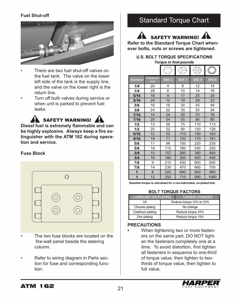
SAFETY WARNING! Refer to the Standard Torque Chart when-ever bolts, nuts or screws are tightened.
PRECAUTIONS• When tightening two or more fasten- ers on the same part, DO NOT tight- en the fasteners completely one at a time. To avoid distortion, first tighten all fasteners in sequence to one-third of torque value, then tighten to two- thirds of torque value, then tighten to full value.
Standard Torque Chart
ATM 16222
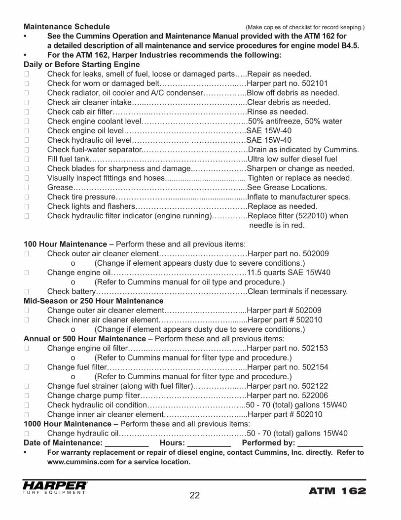
Maintenance Schedule (Make copies of checklist for record keeping.)• See the Cummins Operation and Maintenance Manual provided with the ATM 162 for a detailed description of all maintenance and service procedures for engine model B4.5.• For the ATM 162, Harper Industries recommends the following:Daily or Before Starting Engine Check for leaks, smell of fuel, loose or damaged parts…..Repair as needed. Check for worn or damaged belt……………….………...…Harper part no. 502101 Check radiator, oil cooler and A/C condenser……………..Blow off debris as needed. Check air cleaner intake…...………………………………...Clear debris as needed. Check cab air filter…………...……………………………….Rinse as needed. Check engine coolant level…………………………………..50% antifreeze, 50% water Check engine oil level………………………………………..SAE 15W-40 Check hydraulic oil level…………………. …………………SAE 15W-40 Check fuel-water separator.………………………………….Drain as indicated by Cummins. Fill fuel tank……………………………………………….…...Ultra low sulfer diesel fuel Check blades for sharpness and damage..…….……….…Sharpen or change as needed. Visually inspect fittings and hoses..................................... Tighten or replace as needed. Grease………………………………………………………....See Grease Locations. Check tire pressure…………………...................................Inflate to manufacturer specs. Check lights and flashers…………………………………….Replace as needed. Check hydraulic filter indicator (engine running)…………..Replace filter (522010) when needle is in red.
100 Hour Maintenance – Perform these and all previous items: Check outer air cleaner element………….…………………Harper part no. 502009 o (Change if element appears dusty due to severe conditions.) Change engine oil…………………………………………….11.5 quarts SAE 15W40 o (Refer to Cummins manual for oil type and procedure.) Check battery………………………………………………….Clean terminals if necessary.Mid-Season or 250 Hour Maintenance Change outer air cleaner element…………...……..……....Harper part # 502009 Check inner air cleaner element………….……..…….........Harper part # 502010 o (Change if element appears dusty due to severe conditions.)Annual or 500 Hour Maintenance – Perform these and all previous items: Change engine oil filter……..………………………………..Harper part no. 502153 o (Refer to Cummins manual for filter type and procedure.) Change fuel filter……………………………………………...Harper part no. 502154 o (Refer to Cummins manual for filter type and procedure.) Change fuel strainer (along with fuel filter)……………...…Harper part no. 502122 Change charge pump filter……………………….………….Harper part no. 522006 Check hydraulic oil condition………………………………..50 - 70 (total) gallons 15W40 Change inner air cleaner element………….…………….....Harper part # 5020101000 Hour Maintenance – Perform these and all previous items: Change hydraulic oil……………………………………….…50 - 70 (total) gallons 15W40 Date of Maintenance: __________ Hours: __________ Performed by: _______________• For warranty replacement or repair of diesel engine, contact Cummins, Inc. directly. Refer to www.cummins.com for a service location.
ATM 162 23
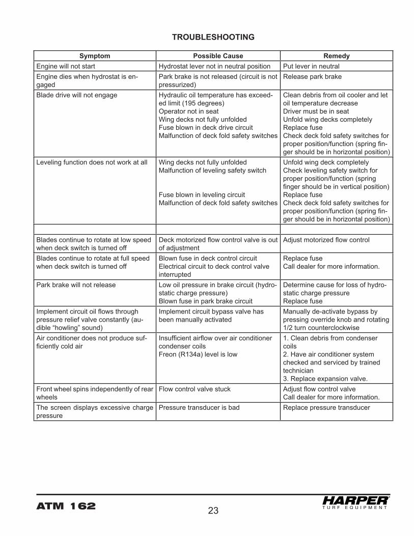
Symptom Possible Cause RemedyEngine will not start Hydrostat lever not in neutral position Put lever in neutralEngine dies when hydrostat is en-gaged
Park brake is not released (circuit is not pressurized)
Release park brake
Blade drive will not engage Hydraulic oil temperature has exceed-ed limit (195 degrees)Operator not in seatWing decks not fully unfoldedFuse blown in deck drive circuitMalfunction of deck fold safety switches
Clean debris from oil cooler and let oil temperature decreaseDriver must be in seatUnfold wing decks completelyReplace fuseCheck deck fold safety switches for proper position/function (spring fin-ger should be in horizontal position)
Leveling function does not work at all Wing decks not fully unfoldedMalfunction of leveling safety switch
Fuse blown in leveling circuitMalfunction of deck fold safety switches
Unfold wing deck completelyCheck leveling safety switch for proper position/function (spring finger should be in vertical position)Replace fuseCheck deck fold safety switches for proper position/function (spring fin-ger should be in horizontal position)
Blades continue to rotate at low speed when deck switch is turned off
Deck motorized flow control valve is out of adjustment
Adjust motorized flow control
Blades continue to rotate at full speed when deck switch is turned off
Blown fuse in deck control circuitElectrical circuit to deck control valveinterrupted
Replace fuseCall dealer for more information.
Park brake will not release Low oil pressure in brake circuit (hydro-static charge pressure)Blown fuse in park brake circuit
Determine cause for loss of hydro-static charge pressureReplace fuse
Implement circuit oil flows through pressure relief valve constantly (au-dible “howling” sound)
Implement circuit bypass valve has been manually activated
Manually de-activate bypass by pressing override knob and rotating 1/2 turn counterclockwise
Air conditioner does not produce suf-ficiently cold air
Insufficient airflow over air conditioner condenser coilsFreon (R134a) level is low
1. Clean debris from condenser coils2. Have air conditioner system checked and serviced by trained technician3. Replace expansion valve.
Front wheel spins independently of rear wheels
Flow control valve stuck Adjust flow control valveCall dealer for more information.
The screen displays excessive charge pressure
Pressure transducer is bad Replace pressure transducer
TROUBLESHOOTING

ATM 16224
Audio/Visual Warnings:Coolant Temperature: • above 205 degrees F – yellow box, single beep • above 215 degrees F – red box, constant beep
Hydraulic Oil Temperature: • above 190 degrees F – yellow box, single beep • above 200 degrees F – red box, constant beep
Fuel Level: • below 1/16th tank – yellow box, single beep
Charge Filter: • Restricted –yellow box, single beep
System Voltage: • below 10V – yellow box, constant beep • above 15V – yellow box, constant beep
Hydrostat Charge Pressure: • below 170psi – yellow box, constant beep • above 450psi – yellow box, constant beep
Electrical Output: • Output fault – Output name shown in yellow, single beep

ATM 162 25
Harper Industries, Inc.151 E. Highway 160Harper, KS 67058
Website: www.harperindustries.com
NOTES
Telephone: 620-896-7381Toll-Free: 800-835-1042Fax: 620-896-7129
E-mail: [email protected]
ATM 16226
R
© 2015 Harper Industries, Inc.All rights reserved. Printed in U.S.A.