manual - british · pdf filecanadian cataloguing in publicatio datn a surface mine rescue...
TRANSCRIPT

Surface Mine Rescue i
Manual
PAPER 1981-4
C E M P R P A P E R ! l 9 8 1 - 4 EMPR c . 2 M A I
>f Ministry of lumbia Energy, Mines and
Petroleum Resources INSPECTION AND ENGINEERING BRANCH
PAPER 1981-4
S U R F A C E MINE RESCUE M A N U A L
Mineral Resources Division Inspection and Engineering Branch
October 1981

Canadian Cataloguing in Publication Data
Surface mine rescue manual
(Paper / Province of British Columbia, Ministry of Energy, Mines and Petroleum Resources, ISSN 0226-9430 ; 1981-4)
Revision of 1977 ed. issued as Paper 1977—1. ISBN 0-7718-8240-8
1. Mine rescue work. I. British Columbia. Mineral Resources Division. Inspection and Engineering Branch. II. Series: Paper (British Columbia. Ministry of Energy, Mines and Petroleum Resources) ; 1981—4.
TN297.S97 1981 622'.8 C81-092088-3
MINISTRY OF ENERGY, MINES AND PETROLEUM RESOURCES VICTORIA
BRITISH COLUMBIA
NOVEMBER 1981

TABLE OF CONTENTS
Page
Introduction 5 The Mechanics and Function of Breathing 9 Electric Shock 11 Oxygen Therapy 13 On the Threshold of Understanding 17 Mine Gases, Their Occurrences, Properties, and Effects on Human Beings and
Treatment of Persons Affected by Them 19
Chart of Mine Gases 49 Instruments Used in Mine-rescue Training Course 53 Chemistry of Fire 63 Escape and Rescue from Burning Buildings 77 Gas Control 79 Filter-type Self-rescuers 81 Self-contained Self-rescuers 85 Demand Apparatus 89 Cold Weather Problems 101 Hypothermia 111 Vehicles and Dumps 117 Rescue from Vehicles 119 Spine Boards 123 Rescue Drum 127 Fibre Ropes 129 Rappelling 133 Rope Work 134
3


INTRODUCTION
The purpose of this manual is designed primarily to give training in basic rescue procedures to be applied following accidents at surface mining operations bearing in consideration the existing physical conditions such as location, additional hazards, and weather. Also the course provides a limited amount of instruction in safe operational procedures for certain circumstances where the information was not readily available from other sources. This instruction is intended only to supplement the safe job instructional training provided by management.
In order to maintain awareness in the accident or hazard statistics at surface mining operations, the surveys of 1978 and 1979 are as follows:
1978 1979
10 2 Falls of people . . . . 0 3 4 Drills 5 3
30 21 45 44
7 4 Gassing 7 4
9 4 9 7
It is hoped that this course will serve as a guide for good practices when people are to be moved from any hazardous situation to a point of safety.
A thorough knowledge of first aid is essential to rescue techniques.
It is suggested that six persons be the desirable number required for rescue purposes, however, accident circumstances will dictate the number of persons available at that time. Additional help may be available from bystanders who should not be expected to operate without guidance or direction from the team captain.
Through training, a team should know what equipment is available (emergency tool boxes) and how to use the equipment and also be aware of hazards involved (gases, fires, etc.).
Signalling: When teams cannot be directed by verbal communication, they may be controlled by the use of horns, gongs, bells, or tugging on a rope.
The code signals set by the British Columbia Ministry of Energy, Mines and Petroleum Resources are as follows:
1 — to advance, if at rest 3 — distress 1 — to stop, if in motion 4 — attention 2 - to rest 5 - retreat
Mention of trade names or commercial products does not necessarily constitute endorsement or recommendation but since they are familiar and presently available for use in our industry, they are used mostly as examples for explanatory purposes.
5

This training manual has been prepared by the staff of the Inspection and Engineering Branch of the Ministry to assist the surface workers to become aware of and be able to recognize surface hazards and to learn how to protect themselves. Rescue equipment should be readily available at all times. This will enable the mine operator to carry out proper rescue procedures.
Suggested requirements for applicants for mine-rescue training are as follows:
— Not younger that 18 years of age, nor over 45 (persons 45 years of age and over may take the course, however, they should not be required to wear breathing apparatus). If successful in the course, their certificate will be restricted to Theory Only.'
— Pass a mine-rescue medical examination prior to taking the course.
— Able to speak, read, and write English.
— Clean shaven — no moustache, beard, or sideburns to interfere with the facepiece of the apparatus worn.
— Familiar with mining conditions and practices.
— Hold a current First-aid Certificate, S.O.F.A. Certificate, or equivalent acceptable, however, all team members are encouraged to have a St. John's standard certificate or equivalent as a minimum.
6
F U N D A M E N T A L PRINCIPLES OF M I N E - R E S C U E TRAINING
FUNDAMENTAL PRINCIPLES OF MINE—RESCUE TRAINING A R E , IN ORDER OF IMPORTANCE:
1. Ensuring the safety of the rescuing team.
2. Endeavouring to rescue or ensuring the safety of the lives of the trapped men.
3. Protecting the mine property from further damage.
4. Rehabilitating the mine.

THE MECHANICS AND FUNCTION OF BREATHING
Many gases found at a mine during normal times can have a harmful effect on the human body if breathed for a period of time in concentrations above the recognized safe limit for that time period.
At the time of a fire at a surface mine great quantities of deadly gases can be given off. The biggest problem confronting the miner at the time of a mine fire is the protection of himself from such gases.
Even during normal times certain circumstances can cause the accumulation of gases or conditions of the air that would make the air harmful to breathe.
Most dangerous gases have a harmful effect on us after they have entered the body as we breathe. If we have an understanding of what happens when we breathe we can better realize what we must do and we must do it to protect ourselves from the various dangerous gases.
MECHANICS OF BREATHING
When we wish to breathe in, the muscles of our chest surrounding the lungs and our diaphragm lying below the lungs pull away from the lungs. This has the same effect as the bellows on an accordion when they are pulled open. A vacuum is created in the lungs by this chest expansion and the outside air rushes in to fill the vacuum.
The air enters the body by way of the nose and throat (pharynx), passes through the voice box (larynx), and then down the windpipe (trachea) and bronchial tubes to the lungs.
When we breathe out the muscles of the chest and the diaphragm push inward against the lungs. Once again this has the same effect as when we push in on the accordion bellows. The air is forced out of the lungs and takes the same path to the outside air as it took on entering.
It can be seen then that air can only get to the lungs if the passageways are clear of obstructions and if the muscular action takes place to cause the expansion and contraction of the chest cavity.
Some gases when breathed can cause the air passages to swell and become obstructed or they can cause an interference with the muscular action that moves the chest and diaphragm.
The muscular action which causes us to breathe is controlled by a portion of the brain at the base of the skull. This portion of the brain is stimulated and controlled by the amount of carbon dioxide gas in the blood.
In summary then, the mechanics of breathing can be likened to a set of bellows. When contracted the air is forced out and when expanded the air is pushed into the bellows by the pressure of the atmosphere. The bellows of our lungs are expanded and contracted by our chest muscles and diaphragm. These muscles must be free to work and before air can enter the lungs the passageways must be clear.
9

I
THE FUNCTION OF BREATHING
The preceding description has outlined in a simplified way how we breathe, that is, how we get air in and out of our lungs. But why do we breathe? What is the purpose of pumping this air in and out?
Everyone knows that normal air contains a certain amount of oxygen and that oxygen is required for life. It is the oxygen content of the air that our body requires and the lungs have a way of making the oxygen content of the air available for use by the body.
Just as a fire cannot burn without oxygen so the human body cannot 'burn' or use digested foodstuffs to produce energy unless it has a supply of oxygen.
When oxygen enters the lungs it is distributed to the millions of tiny air sacs of which the lungs are composed. These tiny air sacs or compartments have walls so thin that the oxygen in the air can pass through the walls of the sacs into the blood itself.
Blood is composed of red and white cells carried in an almost colourless liquid called plasma. A part of the red cell is called haemoglobin (pronounced heem-o-glow-bin) and the haemoglobin attracts oxygen to it.
As the blood circulation brings the red cells into contact with the air sacs of the lungs the oxygen is attracted to the haemoglobin. The haemoglobin then carries the oxygen throughout the body where it does its part in the energy-producing combustion of the digested foodstuffs.
On the blood's return trip to the lungs it carries with it the carbon dioxide that is produced as a waste product of the combustion. As the blood passes the air sacs in the lungs it picks up more oxygen and the carbon dioxide is forced out of the blood into the air sacs. The carbon dioxide is then breathed out with our exhaled breath.
We can see then that as we breathe fresh oxygen is carried to the blood by way of the air sacs in the lungs and carbon dioxide is picked up from the blood by the air sacs and is breathed out into the air.
As the energy-producing combustion and body-building processes cannot carry on without oxygen, just as fire cannot burn without oxygen, it is obvious that without oxygen our bodies cannot continue to live.
Anything that interferes with the steady flow of oxygen to the tissues of the body will slow down or damage the body's function.
10

ELECTRIC SHOCK
The widespread use of electric power through a vast network of energy-bearing wires has resulted in many injuries due to electric current. Some have been unavoidable but often they have been the result of carelessness. Generally, they occur when medical aid is not readily available and first aid must be administered quickly in order to save life.
Many factors influence the severity of electrical injuries. Although high voltages and amperages are dangerous, it must never be forgotten that contact with low voltages can cause death as well as contact with high voltages. Moisture from perspiration or precipitation provides a better contact and increases the severity of the injury, whereas partial insulation of dry clothing lessens the effect. Very often falls from poles follow electric shock and produce further injury, frequently of a very severe nature.
The immediate treatment for a person who has been a victim of electric shock is to remove his contact with the source. This can be best accomplished by throwing a switch if one is present, otherwise a hot stick should be used or some dry nonconducting article with the rescuer wearing rubber gloves and rubber boots. From the foregoing, it will readily be seen that no matter what means are used to remove the patient from the power source, great care must be taken to ensure that the would-be rescuer does not also become a victim.
After the patient is freed, he may be mentally confused or even unconscious. His breathing should be checked and pulse felt and if both are fairly regular he should be kept lying down and quiet. His clothing should be loosened around the neck to ensure free breathing and he should be carefully watched. Such patients upon regaining consciousness will sometimes attempt to get up and run. This action must be carefully guarded against as the sudden exertion could easily result in death due to heart failure. After a victim of electric shock has been at rest with normal respiration for an hour or more, he should be removed to a hospital, preferably as a stretcher case and by ambulance. Persons suffering from electric shock should be advised to contact a doctor before attempting to resume normal activities.
Severe electric shock may paralyse the respiratory centre in the brain causing a cessation of breathing, or it may cause ventricular fibrillation, a form of irregularity of the heart action and is usually fatal. From a first-aid standpoint there is not much one can do to combat this heart condition other than to keep the patient quiet and at rest, however, the lack of breathing should be recognized and some form of artificial respiration started at once after removal of contact from the cause of the injury. Even if the pulse cannot be felt the movement of artificial respiration should be continued for hours if necessary, as many victims of electric shock who appeared dead have been revived by perseverance in the giving of artificial respiration. When such victims are revived they should be kept at rest and examined gently for further injury, fractures, burns, etc., treated for same, and removed to hospital. The importance of keeping a careful watch on these patients cannot be overstressed because secondary shock may result several hours after apparent recovery, especially if they have not been kept quiet and at rest. Under no circumstances should the first aider feel free to leave the patient alone until he is under adequate medical supervision, preferably in a hospital, bearing in mind always that respiratory paralysis may recur after apparent full recovery.
Many persons place a great deal of importance on electric burn treatment but generally speaking such is not a serious first-aid problem. Burns are usually found at the entrance and exit points where the current has passed through the body. These injuries are usually small and deep. A simple dry dressing is about all that is necessary for treatment. Very severe burns are sometimes encountered as a result of electricity, but
11

generally when this condition exists there is not too much hope for a victim's survival and, in fact, severe burning can occur postmortem. Despite the foregoing, it should be remembered that electric burns heal slowly and occasionally severe burning may occur without death. It also should be borne in mind that
burns, with their subsequent shock, have in some cases been the cause of death although the victim survived the initial electric shock. The intelligent first aider will, of course, have done his utmost to refer these patients to a doctor.
The value of oxygen administration and its benefits in the treatment of shock has been brought into prominence quite recently.
SUMMARY OF TREATMENT
• Removal of patient from source of electricity.
• Check breathing and start artificial respiration if necessary.
• After revival keep quiet, at rest, and under observation.
• Examine for and treat all injuries, fractures, burns, etc., with particular emphasis on shock treatment.
• Give no stimulants or opiates.
• Remove to medical attention, preferably hospital.
• Above all, do not clutter up the scene by adding your own body through failure to assure safety from contact while attempting removal of victim from source of electricity.
12
OXYGEN THERAPY
This is a method of administering 100 per cent oxygen by inhalation to victims of asphyxia from gas, carbon monoxide, smoke, and fumes, and suspended respiration from electric shock, drowning, collapse, and other causes.
The approved oxygen equipment consists of the following:
• Control assembly (regulator) with approved pin-indexed yoke.
• Two oxygen bottles (either D or E bottles accepted).
• Two plastic-type masks (disposable).
• Two airways (adult size and small size).
• Suitable wrenches for medical post.
• Carrying case or packboard.
When the bottles have been received from the supplier, or have been returned after being recharged, there is usually a piece of plastic tape covering the oxygen aperture (there is usually a new gasket under this tape). Note: Use only approved gaskets as supplied. This part of the bottle is known as the medical post. You will have noted the aperture for the flow of oxygen, and directly below this are two small holes; this is known as pin-indexing. The purpose of this pin-indexing is to prevent the use of other gases. All different gases are contained in bottles with appropriate pin-indexing, and the equipment used can only be attached to the appropriately pin-indexed bottle. Before attaching the unit, you must first remove the tape and 'crack' the bottle (literally this means to open the valve on top of the medical post to allow some oxygen to escape). The reason for this is to clear out any dust or foreign material that may be lodged in the aperture.
The yoke is now placed over the medical post, and when it is in position and gasket in place it is tightened with the hand screw. BEFORE OPENING V A L V E ON THE BOTTLE MAKE SURE THE R E G U LATOR IS TURNED OFF. TURN COUNTERCLOCKWISE. When the valve on the bottle is turned on, you will get a reading on the high-pressure gauge which tells you the amount of pressure in the bottle.
Attach the tubing from the mask to the unit and open the regulator valve clockwise to the required flow, usually 6 litres is adequate, and allow this to flow through the mask and tubing for a few seconds before placing the mask on the patient. It is advisable to allow this flow in order to clear out any fluid or dust that may be lodged in the tubing. It is difficult to wash and sterilize the mask without having some of the fluid fouling the mask or tube. Many patients have never seen oxygen equipment and it may cause some uneasiness or alarm; to minimize this with a conscious patient it is probably reassuring to the patient to allow him to hold the mask to his face with the oxygen flowing and when he is accustomed to it slip the elastic band of the mask over his head to hold the mask in position. It is always advisable to have the oxygen flowing when applying the mask.
When the patient's respiration and pulse are normal, or nearly so, you can discontinue the use of oxygen. You should, however, watch the patient closely to see that his condition remains stable. If the patient's condition begins to deterioriate, readminister oxygen therapy treatment.
13

The equipment must be stored until further need for it. Check the pressure gauge to see how much oxygen remains in each bottle. Empty or near empty bottles should be recharged or replaced as soon as possible. THE OXYGEN FROM THE BOTTLE IS SHUT OFF (VALVE ON TOP OF MEDICAL POST). 'BLEED' OUT THE OXYGEN IN THE GAUGE SO THAT THE GAUGES READ 'NIL'. This is very important as the gauges can be damaged if left continuously under pressure.
The mask is now sterilized. PLASTIC MASKS OF THIS TYPE CANNOT BE AUTOCLAVED OR BOILED. Cold sterilization is done by carefully washing the mask with some good soap, then using a good antiseptic such as Zephiran Chloride 1/1000 solution as recommended by the manufacturer. Lacking this, a strong solution of Dettol is acceptable. NEVER USE ALCOHOL AS IT WILL DAMAGE THE MASK.
SAFE PRACTICES IN OXYGEN THERAPY
THE FOLLOWING RULES SHOULD BE STRICTLY OBSERVED:
1. Keep oil, grease, greasy clothing, and similar substances away from oxygen regulators, mask, or patient. Remember that oil coming in contact with oxygen under high pressure can explode violently.
2. No smoking should be permitted in a room where oxygen therapy is proceeding. Make sure your patient does not possess matches or smoking material. This no-smoking rule should be rigidly enforced and signs to that effect should be posted conspicuously in your first-aid room.
3. Do not use electrical heating devices or infrared lamps on a patient while oxygen therapy is in progress.
4. Unqualified persons should never attempt to refill a cylinder with makeshift equipment or under any other circumstances. The refilling of small cylinders from larger ones is extremely hazardous and should be avoided. Return your empty cylinders to qualified charging plants for refilling under recognized safety and control procedure.
5. Do not store oxygen cylinders near flammable or combustible materials such as oil, grease, gasoline, alcohol, or ether, or near sources of heat such as boilers or steam pipes. Store in a cool place. Although oxygen itself does not burn or explode on contact with flame it violently supports combustion.
6. Keep oxygen cylinders in service or in storage secured in an upright position. Do not permit them to be dropped or to strike each other violently, as a valve might be opened whereupon the cylinders could become a dangerous projectile.
7. Before attaching gauges or regulator to cylinder, crack the cylinder valve in order to clear out any foreign matter which may be in the aperture. Turn opening away from you while doing so.
8. After regulator is in place attach the facepiece, making sure that the litre flow regulating valve is in the off position. Then turn on cylinder valve. This should give the tank pressure reading on the pressure gauge. When assured that this gauge is operating properly turn on litre flow valve to desired
14

flow. This will clear out any moisture or foreign matter which may be in the tubing. You may then apply the facepiece or mask to the patient.
Observance of these rules may prevent serious and utterly unwarranted accidents.
15

ON THE THRESHOLD OF UNDERSTANDING
A great deal of attention will be paid to the toxicity of chemicals as they affect the human body. All chemicals used in industry that have a toxic effect on workers will have a maximum allowable concentration to which the employee can be exposed for an 8-hour day. These concentrations will be expressed in parts per million (ppm).
For many of us 1 part per million is about as hard to visualize as the national debt. The following from Forestry Facts helps indicate what 1 part per million really represents under various conditions:
• 1 ounce of sand in 31 tons
• 1 inch in 16 miles
• 1 minute in 1.9 years
• 1 ounce of dye in 7,503 gallons
• 1 square inch in 1/6 acre
• 1 pound in 500 tons
• 1 cent in $10 000
• 1/6-inch thickness in a pile 1 mile high
Keep these comparisons handy somewhere, they might sharpen your threshold limit sense of values.
THRESHOLD LIMIT VALUES
The degree of effect of both gaseous and particulate contaminants depends largely upon the airborne concentration and the amount of exposure.
Accordingly, a listing of threshold limit values (TLV's) is published yearly by the American Conference of Governmental Industrial Hygienists as guides for exposure concentration which, it is believed, a healthy individual normally can tolerate for 8 hours a day, 5 days a week, without harmful effects.
Airborne particulate concentrations are generally listed as milligrams per cubic metre of air (mg/m3) and gaseous concentrations are listed as parts per million or per cent by volume.
17

1

MINE GASES, THEIR OCCURRENCES, PROPERTIES, AND EFFECTS ON HUMAN BEINGS AND TREATMENT OF PERSONS AFFECTED BY THEM
AIR
Air is the transparent medium surrounding the earth in which plants, animals, and human beings live and breathe. It is a mixture of several gases which, though ordinarily invisible, can be weighed, compressed to a liquid, or frozen to a solid.
Pure dry air at sea level contains by volume the following gases: oxygen (O2), 20.94 per cent; nitrogen (l\h), 78.09 per cent; carbon dioxide (CO2), 0.03 per cent; and argon (Ar), 0.94 per cent. Traces of other gases such as hydrogen, helium, etc., are also present.
The air in a well-ventilated area seldom shows any depletion of the oxygen content.
Air may be contaminated by the presence of other gases such as carbon monoxide, sulphur dioxide, hydrogen sulphide, methane, oxides of nitrogen, and excess carbon dioxide. The presence of these gases may be due to any of the following:
• Aftereffects of blasting or other explosions.
• Aftereffects of mine fires.
• Exudations from ore or country rock, as with methane.
• Decay of timber in poorly ventilated areas.
• Absorption of oxygen by water or oxidation of timber or ore.
• Use of diesel and gasoline motors in enclosed areas.
• Gas carried with thermal water or carbon dioxide.
• Gas carried chemically by various chemicals and reagents.
Except in the case of fire, positive ventilating currents of sufficient quantity will prevent any dangerous accumulation of these gases. Gases may affect people either by their combustible, explosive, or toxic qualities, or, if inert, by the displacement of oxygen. The effects may be due to varying atmospheric conditions and may be classified as follows:
ALTITUDE
Breathing becomes more laborious due to the decrease in oxygen content as the altitude increases. This is not dangerous unless conditions are extreme or the labour arduous.
HUMIDITY
High temperatures with high humidity are very enervating and cause considerable discomfort.
19

GAS - OXYGEN (0 2) AND OXYGEN DEFICIENCY
RELATIVE WEIGHT
0.5
1.1 o; 1.5
2.0
S E E K S HIGH P L A C E S
AIR = 1
S E E K S LOW P L A C E S
E X P L O S I V E R A N G E per cent
90
80 —
70 —
60 —
50 —
40 —
30 —
20 —
10 —
N O N F L A M M A B L E
OTHER PROPERTIES
Colour: None. Odour: None. Taste: None. Other: Detected by candle, safety lamp, these go out at approximately 16 per cent oxygen.
HOW DEPLETED
Oxygen deficiency caused by humans breathing in confined space, absorption of oxygen by water, oxygen being consumed by fire, etc.
THRESHOLD LIMIT V A L U E AND EFFECT ON HUMANS
Mine air should have at least 19.5 per cent oxygen. High concentration not harmful. Essential to life. Early symptions of oxygen deficiency — buzzing in ears, rapid breathing, confusion of mind, unconsciousness.
TREATMENT OF PERSONS AFFECTED (oxygen deficiency)
Remove to fresh air, give oxygen — artificial respiration if breathing stopped.
20
TEMPERATURE
High temperatures with low humidity are not dangerous except from the blistering effect of heat.
IMPURE AIR
• Air deficient in oxygen is not dangerous unless the oxygen content is below 16 per cent, or unless the oxygen has been displaced by toxic gases.
• Nontoxic gaseous impurities are not dangerous unless gases have displaced the oxygen content to below 16 per cent.
• Some toxic gaseous impurities, even in very low concentrations, have deadly effects. Effects may be sudden or gradual according to the concentration of impurity.
OXYGEN (0 2)
Oxygen, a colourless, odourless, and tasteless gas, is the most important constituent of air. It is necessary for the support of life and combustion. Men breathe most easily and work best when the air contains approximately 21 per cent oxygen but they can live and work, though not as well, when there is less oxygen. When the oxygen content is about 17 per cent, men at work will breathe a little faster and more deeply. The effect is about the same as when going from sea level to an altitude of 5,000 feet. Men breathing air containing as little as 15 per cent oxygen usually become dizzy, notice a buzzing in the ears, have a rapid heartbeat, and often suffer headaches. Very few men are free from these symptoms when the oxygen in the air falls to 10 per cent. Mine air should contain not less than 19.5 per cent oxygen.
The flame of a safety lamp or candle is extinguished when the oxygen falls to about 16 per cent. A carbide lamp flame will burn in an atmosphere containing as little as 12.5 per cent oxygen.
Since oxygen is more soluble in water than nitrogen, air in a confined area when exposed to water will probably have a lowered oxygen content. As an example the oxygen content of the air from a hydraulic compressed-air plant is lowered to about 17.7 per cent oxygen and a consequent rise in nitrogen content occurs.
Oxygen percentage higher than the normal 20 to 21 per cent apparently has no injurious effects on men. This is found to be the case in the use of self-contained oxygen breathing apparatus. There is no noticeable effect after successive periods of wear. Oxygen in high percentages, as used with the oxygen breathing apparatus, helps men to work with less fatigue. However, it is dangerous to breathe pure oxygen at pressure much higher than 15 pounds per square inch for a very long time. Lorrain Smith, the well-known physicist, states that irritating effects of oxygen are only found in human beings after they have been exposed for 48 hours or more in an atmosphere containing 80 per cent oxygen.
The effects of oxygen deficiency near or below sea level are the same as those due to the reduction of oxygen in high altitudes. At approximately 7 per cent oxygen the face becomes leaden in colour, the mind becomes confused, and the senses dulled. When there is no oxygen in the atmosphere loss of consciousness
21

GAS - CARBON DIOXIDE (C0 2)
RELATIVE WEIGHT
1.5 >
0.5
1.5
2.0
S E E K S HIGH P L A C E S
AIR = 1
S E E K S LOW P L A C E S
E X P L O S I V E R A N G E percent
90 -80
70
60 -50 -40 -30 -20
10 -N O N F L A M M A B L E
OTHER PROPERTIES
Colour: None. Odour: None. Taste: Acid if breathed in large quantities.
HOW FORMED
Oxidation of organic materials, rotting timber, burning wood, blasting, diesel engines, humans breathing, and as a product of complete combustion of organic materials.
THRESHOLD LIMIT V A L U E AND EFFECT ON HUMANS
T L V = 5 000 ppm - stimulates breathing, 50 000 ppm - increases respiration 300 per cent, 100 000 ppm — can be endured for only short periods.
TREATMENT OF PERSONS A F F E C T E D
Remove to fresh air, give oxygen, artificial respiration if breathing stopped.
22

occurs in a few seconds without any warning symptoms. J . S. Haldane, the British physicist, says that loss of consciousness in air deprived of oxygen is quicker than in drowning; not only is the supply of oxygen cut off, but oxygen previously in the lungs is rapidly removed and used up, loss of consciousness is quickly followed by convulsions, then by cessation of respiration. Oxygen may be so lacking as to imperil life before one realizes the danger.
Some of the causes of oxygen deficiency are:
• Absorption by water or certain types of rock, ore, or fill.
• The breathing of men in confined space.
• Displacement by carbon dioxide, carbon monoxide, or other gases.
Heating conditions or combustion.
OXYGEN DEFICIENCY
Oxygen Present Effect per cent
21 Breathing easiest. 17 Breathing faster and deeper. 15 Dizziness, buzzing noise, rapid pulse, headache, blurred vision. 9 May faint or become unconscious. 6 Movement convulsive, breathing stops, shortly after heart stops.
CARBON DIOXIDE (C0 2 )
Carbon dioxide, an inert gas, is a product of the decomposition and/or combustion of organic compounds in the presence of oxygen, and also of the respiration of men and animals. It is a colourless, odourless gas which, when breathed in large quantities, may cause a distinctly acid taste. It will not burn or support combustion. Carbon dioxide, being heavier than air, is often found in low places and abandoned mine workings and is a normal constituent of mine air. The proportions of carbon dioxide in mine air is increased by the process of breathing, by the burning of flame lamps, by fires, explosions, and blasting, or by escaping with thermal water. Clinical investigations indicate that carbon dioxide influences the respiratory rate. This rate increases rapidly with increasing amounts of carbon dioxide.
The following table shows the effect upon a human being of increasing amounts of CO2 in the air breathed:
PHYSIOLOGICAL EFFECTS OF CARBON DIOXIDE
Carbon Dioxide In Atmosphere Increase in Respiration per cent
0.5 Maximum allowable for an 8-hour day. 0.05 Slight. 2.0 50 per cent. 3.0 100 per cent. 5.0 300 per cent and laborious.
10.0 Cannot be endured for more than a few minutes.
23
GAS - CARBON MONOXIDE (CO)
RELATIVE WEIGHT
£o£C>:
0.5
1.5
2.0
S E E K S HIGH P L A C E S
AIR = 1
S E E K S y LOW
P L A C E S
E X P L O S I V E R A N G E per cent
90
80
OTHER PROPERTIES
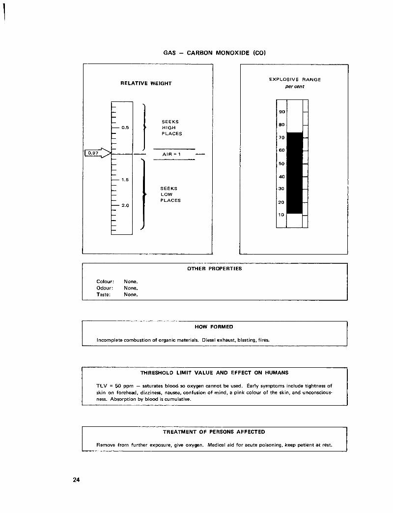
Colour: None. Odour: None. Taste: None.
HOW FORMED
Incomplete combustion of organic materials. Diesel exhaust, blasting, fires.
THRESHOLD LIMIT V A L U E AND EFFECT ON HUMANS
T L V = 50 ppm — saturates blood so oxygen cannot be used. Early symptoms include tightness of skin on forehead, dizziness, nausea, confusion of mind, a pink colour of the skin, and unconsciousness. Absorption by blood is cumulative.
TREATMENT OF PERSONS AFFECTED
Remove from further exposure, give oxygen. Medical aid for acute poisoning, keep patient at rest.
24

Carbon dioxide in air has these effects when the oxygen content remains approximately normal and the individual is at rest. Moving around or working increases the symptoms and the danger is greater than when the individual is resting. Concentrations of over 5 per cent carbon dioxide in the air are usually accompanied by an appreciable lowering of the oxygen content. Carbon dioxide in mine air should be not more than 0.50 per cent.
NITROGEN (N 2)
Nitrogen is a colourless, odourless, and inert gas. It is not combustible nor will it support combustion. It has no physiological effect on men and is only dangerous if it occurs in such concentrations that it dilutes the air sufficiently to cause the oxygen content to fall below a safe limit. This dilution may result from the oxidation of various substances or from the consumption of an active fire, thus robbing the mine atmosphere of a part of its oxygen. The oxygen may be reduced to a very low point and the residual nitrogen mixed with the products of combustion such as carbon dioxide, carbon monoxide, sulphur dioxide, etc. Although nitrogen is the main component of pure air (78.09 per cent), as a gas by itself it is slightly lighter than air. Nitrogen has a relative weight of 0.97 and the threshold limit value is 81 per cent.
CARBON MONOXIDE (CO)
Carbon monoxide gas constitutes one of the greatest hazards to life in mining. It is one of the products of combustion in normal blasting operations and in the use of diesel motors and is dangerous unless adequate ventilation is provided. It is also produced by such abnormal occurrences as mine fires or gas explosions. It is a product of incomplete combustion and is formed wherever organic compounds are burned in an atmosphere with insufficient oxygen to carry the process of burning or oxidation to completion. It is a colourless, odourless, and tasteless gas which, when breathed in even low concentrations, will produce symptoms of poisoning. Carbon monoxide will burn and air that contains 12.5 to 74 per cent of carbon monoxide will explode if ignited. It is only slightly soluble in water and is not removed from the air to any extent by water sprays. It is slightly lighter than air having a specific gravity of 0.967.
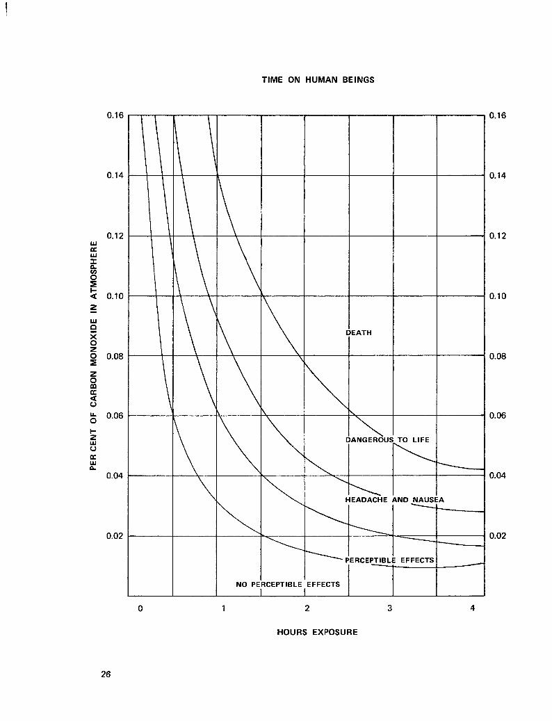
Carbon monoxide in excess of 0.01 per cent, if breathed indefinitely, may eventually produce symptoms of poisoning; 0.02 per cent will produce slight symptoms after several hours' exposure. When four parts in 10 000 (0.04 per cent) are present and the exposure is for 2 to 3 hours, headache and discomfort usually occur. With moderate exercise, when 0.12 per cent is present, slight palpitation of the heart will occur in 30 minutes, tendency to stagger in 1.5 hours, and confusion of mind, headache, and nausea in 2 hours. In concentrations of 0.20 to 0.25 per cent unconsciousness usually occurs in about 30 minutes. The effect of high concentrations may be so sudden that one has little or no warning before collapsing. The carbon monoxide content of the air in which men are employed for a period of 8 hours should not exceed 0.005 per cent or 50 parts per million.
HOW CARBON MONOXIDE ACTS
The oxygen absorbed from the air in the lungs is normally taken up by the blood in the form of a loose chemical combination with the red colouring matter (haemoglobin) of the corpuscles, and in this form it is carried to the tissues where it is used. Haemoglobin forms a much more stable compound with carbon monoxide than with oxygen and when saturated with the former it cannot take up oxygen.
25
26

The affinity of haemoglobin for carbon monoxide is about 300 times its affinity for oxygen; hence when even a small percentage of carbon monoxide is present in the air breathed the haemoglobin will absorb the carbon monoxide in preference to the oxygen. When carbon monoxide is absorbed by haemoglobin it reduces the capacity of the haemoglobin for carrying oxygen to the tissues to a proportionate extent. It is this interference with the oxygen supply to the tissues that produces the symptoms of poisoning.
The symptoms of poisoning more or less parallel the extent of blood saturation. The first definite symptoms, during rest, make their appearance when 20 or 30 per cent of the haemoglobin is combined with carbon monoxide. Unconsciousness takes place at about 50 per cent saturation and death occurs at about 80 per cent.
According to experiments conducted by the United States Bureau of Mines the symptoms produced by various percentages of carbon monoxide in the blood are as follows:
The symptoms decrease in number with the increase in the rate of saturation. If exposed to high concentrations the victim may experience but few symptoms. The rate at which a man is overcome and the sequence in which the symptoms appear depend on several factors; the concentration of gas, the extent to which he is exerting himself, the state of his health, individual susceptibility, and the temperature, humidity, and air movement to which he is exposed.
Exercise, high temperature, and humidity, with little or no air movement, tend to increase respiration and heart rate and consequently result in more rapid absorption of carbon monoxide.
TREATMENT FOR CARBON MONOXIDE POISONING
The onset of carbon monoxide poisoning may be either sudden or gradual depending on the concentration and period of exposure. Interest usually centres in the treatment of the acute or sudden form. In the treatment of the chronic or gradual form of poisoning the most important factors are avoiding further exposure and taking a thorough rest. In the treatment of acute carbon monoxide poisoning the most important thing is to get the gas out of the blood as rapidly as possible, thus decreasing the possibility of serious aftereffects or even loss of life through failure of the heart and respiration. As soon as the patient begins to breathe air in which there is no carbon monoxide the process of eliminating the gas from the blood will begin naturally. However, this normal elimination is slow and often has serious effects. It requires possibly 8 to 15 hours to reduce the carbon monoxide haemoglobin to 10 per cent of the total haemoglobin. Inhalation of pure oxygen will remove the carbon monoxide from the blood four or five
Percentage of Blood
Saturation Symptoms
0-10 10-20 20-30 30-40 40-50 50-60 60-70 70-80
None Tightness across forehead, possible headache. Headache, throbbing in temples. Severe headache, weakness, dizziness, dimness of vision, nausea, vomiting, and collapse. Same as 30-40, with more possibility of fainting and collapse, increased pulse and respiration. Fainting, increased pulse and respiration, coma with intermittent convulsions. Coma with intermittent convulsions, depressed heart action and respiration, possible death. Weak pulse and slowed respiration, respiratory failure, and death.
27

GAS - OXIDES OF NITROGEN (NO and N0 2 )
RELATIVE WEIGHT
niC>-
0.5
1.5
2.0
S E E K S HIGH P L A C E S
AIR = 1
S E E K S LOW P L A C E S
E X P L O S I V E R A N G E per cent
90 —
80 —
70 —
60 —
50 —
40 —
30 —
20 —
10 —
N O N F L A M M A B L E
OTHER PROPERTIES
Colour: None in small concentrations; reddish brown in higher concentrations. Odour: None. Taste: None.
HOW FORMED
Diesel exhaust, blasting with dynamite, and ammonium nitrate blasting agents.
THRESHOLD LIMIT V A L U E AND EFFECT ON HUMANS
T L V = 5 ppm — corrosive to tissues of lungs and respiratory tract. Causes oedema of lungs.
TREATMENT OF PERSONS A F F E C T E D
Remove to fresh air, give oxygen and complete rest. Seek medical aid.
28
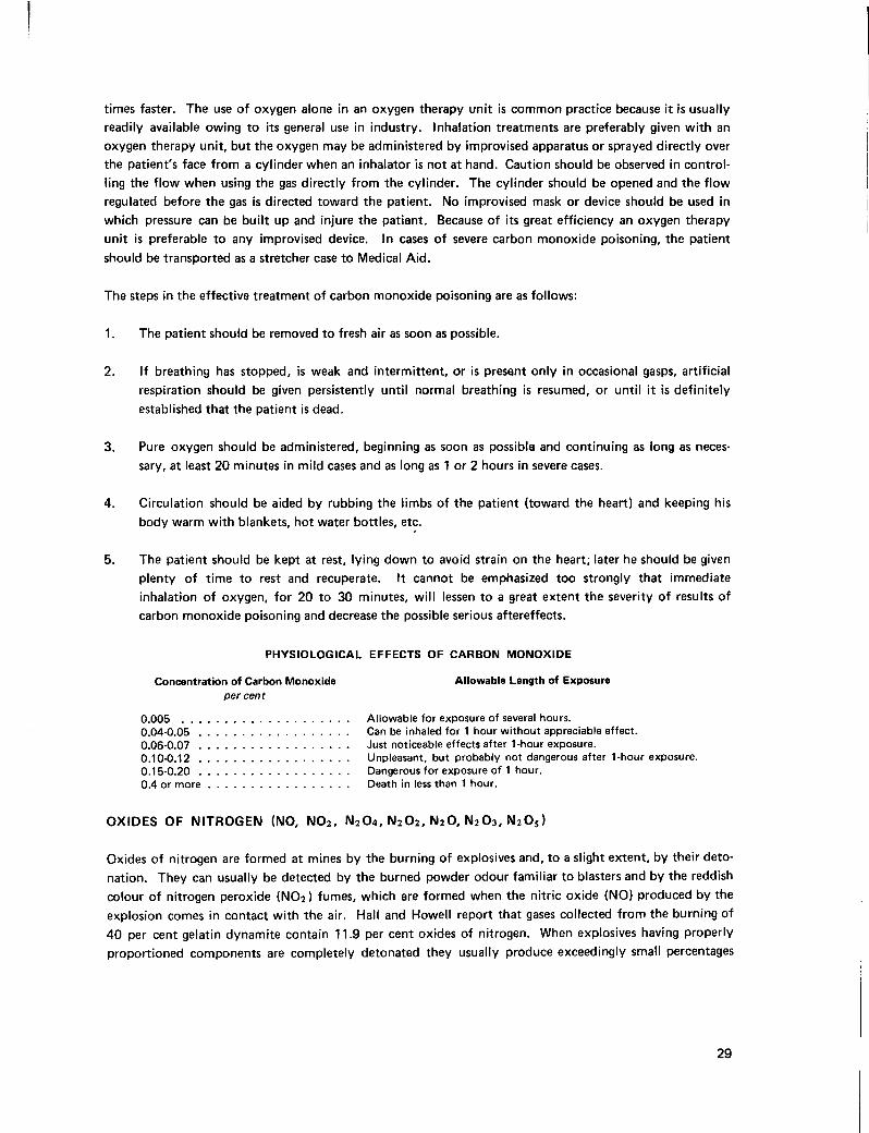
times faster. The use of oxygen alone in an oxygen therapy unit is common practice because it is usually readily available owing to its general use in industry. Inhalation treatments are preferably given with an oxygen therapy unit, but the oxygen may be administered by improvised apparatus or sprayed directly over the patient's face from a cylinder when an inhalator is not at hand. Caution should be observed in controlling the flow when using the gas directly from the cylinder. The cylinder should be opened and the flow regulated before the gas is directed toward the patient. No improvised mask or device should be used in which pressure can be built up and injure the patient. Because of its great efficiency an oxygen therapy unit is preferable to any improvised device. In cases of severe carbon monoxide poisoning, the patient should be transported as a stretcher case to Medical Aid.
The steps in the effective treatment of carbon monoxide poisoning are as follows:
1. The patient should be removed to fresh air as soon as possible.
2. If breathing has stopped, is weak and intermittent, or is present only in occasional gasps, artificial respiration should be given persistently until normal breathing is resumed, or until it is definitely established that the patient is dead.
3. Pure oxygen should be administered, beginning as soon as possible and continuing as long as necessary, at least 20 minutes in mild cases and as long as 1 or 2 hours in severe cases.
4. Circulation should be aided by rubbing the limbs of the patient (toward the heart) and keeping his body warm with blankets, hot water bottles, etc.
5. The patient should be kept at rest, lying down to avoid strain on the heart; later he should be given plenty of time to rest and recuperate. It cannot be emphasized too strongly that immediate inhalation of oxygen, for 20 to 30 minutes, will lessen to a great extent the severity of results of carbon monoxide poisoning and decrease the possible serious aftereffects.
PHYSIOLOGICAL EFFECTS OF CARBON MONOXIDE
Concentration of Carbon Monoxide Allowable Length of Exposure per cent
0.005 Allowable for exposure of several hours. 0.04-0.05 Can be inhaled for 1 hour without appreciable effect. 0.06-0.07 Just noticeable effects after 1-hour exposure. 0.10-0.12 Unpleasant, but probably not dangerous after 1-hour exposure. 0.15-0.20 Dangerous for exposure of 1 hour. 0.4 or more Death in less than 1 hour.
OXIDES OF NITROGEN (NO, N 0 2 , N 2 0 4 , N 2 0 2 , N 2 0 , N 2 0 3 , N 2 0 5 )
Oxides of nitrogen are formed at mines by the burning of explosives and, to a slight extent, by their detonation. They can usually be detected by the burned powder odour familiar to blasters and by the reddish colour of nitrogen peroxide (N0 2) fumes, which are formed when the nitric oxide (NO) produced by the explosion comes in contact with the air. Hall and Howell report that gases collected from the burning of 40 per cent gelatin dynamite contain 11.9 per cent oxides of nitrogen. When explosives having properly proportioned components are completely detonated they usually produce exceedingly small percentages
29
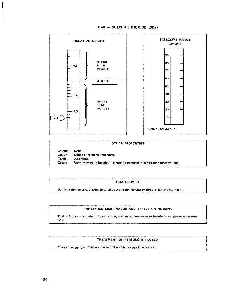
GAS - SULPHUR DIOXIDE (S0 2)
RELATIVE WEIGHT
0.5
1.5
2.0
S E E K S HIGH P L A C E S
AIR = 1
S E E K S LOW P L A C E S
E X P L O S I V E R A N G E percent
90
80
70
60
50
40
30
20
10
N O N F L A M M A B L E
OTHER PROPERTIES
Colour: None. Odour: Strong pungent sulphur smell. Taste: Acid taste. Other: Very irritating to breathe — cannot be tolerated in dangerous concentrations.
HOW FORMED
Burning sulphide ores, blasting in sulphide ores, sulphide dust explosions. Some diesel fuels.
THRESHOLD LIMIT V A L U E AND EFFECT ON HUMANS
T L V = 5 ppm — irritation of eyes, throat, and lungs, intolerable to breathe in dangerous concentrations.
TREATMENT OF PERSONS A F F E C T E D
Fresh air, oxygen, artificial respiration, if breathing stopped medical aid.
30

of oxides of nitrogen which are considered harmless. Explosives from which the wrapper has been removed may produce harmful percentages of oxides of nitrogen, even when detonated. Diesel engines also produce oxides of nitrogen.
Oxides of nitrogen corrode the respiratory passages and the breathing of relatively small quantities may cause death. The effect is unlike that of carbon monoxide in that a person may apparently recover and then suddenly die several days later. Nitrogen peroxide (NO2) is probably the most irritating of the oxides of nitrogen. Its effect on the respiratory passages usually are not manifest until several hours after exposure when oedema and swelling take place. This irritation may be followed by bronchitis or pneumonia, frequently with fatal results. One-hundredth (0.01) per cent of nitrogen peroxide may cause dangerous illness if breathed for a short time and 0.07 per cent is fatal if breathed for about 30 minutes or less. The maximum acceptable concentration and threshold limit value for this gas are both 5 parts per million. In other words, the concentration for any short period exposure must not be greater than that for an 8-hour exposure.
PHYSIOLOGICAL EFFECTS OF OXIDES OF NITROGEN
Concentration of Oxides of Nitrogen
Parts Per Per Cent Effect
Million
5 0.0005 Maximum allowance for 8-hour day. 60 0.006 Minimum causing immediate throat irritation.
100 0.01 Minimum causing coughing. 100-150 0.01 -0.015 Dangerous for even short exposure. 200-700 0.02-0.07 Rapidly fatal for short exposure.
SULPHUR DIOXIDE (S0 2)
Sulphur dioxide is another gas produced by burning sulphide ores or by blasting in sulphide ores or explosions of sulphide ore dust. Some diesel fuels will produce sulphur dioxide when used in a diesel engine.
This gas has a strong sulphur smell which is suffocating and very irritating to breathe. It is so irritating to breathe that it cannot be tolerated for any length of time in dangerous concentrations. A person's natural reaction when he encounters this gas is to get out of it and this, of course, should be done.
If forced to breathe this gas for any length of time coughing and nausea result. The gas will affect the lungs in much the same manner as oxides of nitrogen and hydrogen sulphide. Irritation of the respiratory tract and lungs will cause oedema.
EFFECTS OF SULPHUR DIOXIDE
Concentration of Sulphur Dioxide
Parts Per Per Cent Effect
Million
5 0.0005 Maximum allowable for an 8-hour day. 20 0.002 Coughing and irritation to eyes, nose, and throat.
150 0.015 May be endured for several minutes. 400 0.04 Impossible to breathe.
31

GAS - METHANE (CH 4)
RELATIVE WEIGHT
| 0.55 ^ >
-
— 0.5
— >
— >
1.5
2.0
S E E K S HIGH P L A C E S
AIR = 1
S E E K S LOW P L A C E S
E X P L O S I V E R A N G E per cent
OTHER PROPERTIES
Colour: None. Odour: None — often associated with other sulphurous gases. Taste: None.
HOW FORMED
Decomposition of vegetable matter. Released from coal seams or some rocks when mining carried out or when diamond drilling.
THRESHOLD LIMIT V A L U E AND EFFECT ON HUMANS
Nonpoisonous but due to flammability men must withdraw at 2.5 per cent. At 1.25 per cent switch off electrics. Blasting stopped at 1 per cent.
TREATMENT OF PERSONS AFFECTED
Nontoxic. If concentration causes oxygen deficiency, treat as such.
32

The threshold limit value of sulphur dioxide is a low 5 parts per million. Sulphur dioxide is highly soluble in water, in fact it is one of the most soluble gases found at mines. It is a very heavy gas and has a relative weight of 2.2. It can, therefore, be expected to accumulate in low places. Sulphur dioxide is colourless and has a distinctly acid taste.
METHANE (CH 4)
Methane or marsh gas is encountered in some metal mines in the Bridge River area and in practically all coal mines in British Columbia. Flow of the gas is variable and is occluded in the pores of the coal. It is formed by the decomposition of organic matter in the presence of water and the absence of air or oxygen. It can be seen in the form of bubbles in stagnant pools, hence the name marsh gas.
Methane is a colourless, odourless, and tasteless gas. An odour caused by the presence of other gases such as hydrogen sulphide often accompanies it. Methane will burn with a pale blue nonluminous flame and still air that contains 5 to 15 per cent of methane and 12 per cent or more of oxygen will explode and this is its chief danger. However, the inflammable and explosive range of methane is variable and all occurrences of the gas should be considered as dangerous. Where the occurrence of methane is suspected or known adequate ventilation to dilute the gas to a harmless percentage is important.
Methane is considerably lighter than air and when found at mines is usually in high places. Accumulations of the gas may be encountered in poorly ventilated mine workings.
Methane has no direct effect upon men but it may displace the oxygen content of the air to such an extent as to cause oxygen deficiency. An open-flame lamp or a spark may cause an explosion. The British Columbia Coal Mine Regulation Act requires that all men be withdrawn from any work area when the methane content of the general body of air in that area reaches 2.5 per cent. This Act also requires electrical circuits to be isolated in any work area when the methane content in the general body of air in that area reaches 1.25 per cent and that no blasting or shotfiring is done when the methane content exceeds 1 per cent.
HYDROGEN SULPHIDE (H2S)
Hydrogen sulphide is one of the most poisonous gases known. Fortunately only traces of it are ordinarily found in mine operations. In some respects it is more dangerous than hydrogen cyanide. In low concentrations its distinctive rotten egg odour is noticeable, but in high concentrations the sense of smell is quickly paralysed by the action of the gas on the respiratory centre and cannot be relied on for warning. The gas has a specific gravity (SG) of 1.19 and, being heavier than air, may collect at low points.
Hydrogen sulphide inhaled in a sufficiently high concentration produces immediate asphyxiation; in low concentrations it produces inflammation of the eyes and respiratory tract and sometimes leads to bronchitis, pneumonia, and oedema of the lungs.
Subacute poisoning may be produced by long exposure to concentrations as low as 0.005 per cent. Immediate collapse usually results from exposure to concentrations of 0.06 to 0.1 per cent, and death quickly ensues. The 8-hour daily exposure should not exceed 0.001 per cent or 10 parts per million.
33

GAS - HYDROGEN SULPHIDE (H 2S)
RELATIVE WEIGHT
0.5
1.5
2.0
S E E K S HIGH P L A C E S
AIR = 1
S E E K S LOW P L A C E S
E X P L O S I V E R A N G E per cent
OTHER PROPERTIES
Colour: None. Odour: Rotten egg smell in low concentrations. Taste: None. Irritates nose, throat, eyes, etc.
HOW FORMED
Burning sulphide ores, explosions of dusts from sulphide ores, and hydrochloric acid on sulphide concentrate.
THRESHOLD LIMIT V A L U E AND EFFECT ON HUMANS
T L V = 10 ppm — paralyses respiratory centre. Low concentrations cause oedema of lungs, bronchitis, and pneumonia.
TREATMENT OF PERSONS A F F E C T E D
Remove to fresh air, give oxygen, artificial respiration if breathing stopped, get medical aid and advise of exposure to hydrogen sulphide.
34

PHYSIOLOGICAL EFFECTS OF HYDROGEN SULPHIDE
Per Cent Time Effect
0.001 Maximum allowable for 8-hour day.
0.005-0.010 1 hour Subacute poisoning — 1. mild eye irritation, 2. mild respiratory irritation.
0.02 -0.03 1 hour Subacute poisoning — 1. marked eye irritation, 2. marked respiratory irritation.
0.05 -0.07 0.5-1 hour Subacute to acute poisoning — unconsciousness.
0.10 -0.20 Minutes Acute poisoning — 1. unconsciousness, 2. death.
or more
When explosions of dust occur in blasting operations in sulphide orebodies, the resulting gases may contain varying amounts of hydrogen sulphide, along with sulphur dioxide, and possibly other sulphur gases. Hydrogen sulphide is highly explosive with an explosive range of 4.3 to 46 per cent.
HYDROGEN (H 2)
Hydrogen is a colourless, odourless, and tasteless gas. It is very much lighter than air with a relative weight of 0.07 and is highly flammable. Hydrogen is explosive over a broad range of concentrations, for example, from 4.1 to 74 per cent. It will explode with as little as 5 per cent oxygen in the air and is most violently explosive at concentrations of 7 to 8 per cent.
Hydrogen is not a toxic gas and as with methane the only danger of breathing it is when the concentration is such that the oxygen content of the air is reduced.
The only real hazard of hydrogen gas then is from its flammable and explosive properties.
Hydrogen gas is normally found in mine air in only very small quantities. It can, however, be produced at the time of mine fires when rock is heated to incandescence and as a result of incomplete combustion.
The most common source of hydrogen gas under normal circumstances is in the battery charging area. The electrolytic action which takes place during battery charging releases hydrogen gas. Charging stations must, therefore, be well ventilated and smoking, electric arcs, etc., must be avoided in them.
From a trace to as much as 9 per cent can be found in crevices of a coal face after blasting. It is formed here as a result of incomplete combustion of explosives and by distillation of the coal caused by the explosion.
Hydrogen gas is usually present in amounts up to 2 per cent in gas from ordinary mine fires and is always present after coal dust explosions. Coal gas can contain as much as 50 per cent hydrogen.
Hydrogen gas can be detected with the multi-gas detector and with vacuum bottles. A vacuum bottle is simply a sealed bottle from which all air and other gases have been removed. The bottle is taken into the
35

GAS - HYDROGEN (H 2)
RELATIVE WEIGHT
0.5
1.5
2.0
S E E K S HIGH P L A C E S
AIR = 1
S E E K S LOW P L A C E S
E X P L O S I V E R A N G E percent
90
80
N O N F L A M M A B L E
OTHER PROPERTIES
Colour: None. Odour: None. Taste: None. Other: Highly explosive over wide range.
HOW FORMED
Electrolysis in battery changing stations. Incomplete combustion and molecular breakdown of water when rock heated to incandescence. Present in coal gas and caused by blasting in coal.
THRESHOLD LIMIT V A L U E AND EFFECT ON HUMANS
Nontoxic. Only physiological effect is when oxygen is depleted.
TREATMENT OF PERSONS AFFECTED
As for oxygen deficiency.

suspected atmosphere and the vacuum is released, allowing the atmosphere to enter the bottle. The bottle is then sealed and sent to a laboratory for analysis of the contents.
Almost the same result as a vacuum bottle can be obtained by filling a clean bottle with water and emptying the bottle in the suspected atmosphere. As the water is dumped from the bottle the surrounding atmosphere enters the bottle which can then be sealed and sent out for analysis.
The flame safety lamp will indicate the presence of hydrogen or any flammable gas. Concentrations of the gas, however, cannot be determined with the safety lamp.
Hydrogen is not a common gas at mines but when it occurs its explosive nature makes it extremely dangerous. We should be aware that it can be released at the time of mine fires.
AUTOMOTIVE BATTERIES
There is always danger that an automotive battery may explode when using booster cables around it if the hookup is not made correctly.' Hydrogen is emitted through the vents in the cell caps. Any electric spark can set off a powerful explosion and electric sparks easily occur when making a connection to a battery. Using boosters is easy if you follow the right steps. If you do not you could damage the car's electrical system or even cause a battery explosion.
1. Be sure both batteries are of the same voltage. A 12-volt battery has six filler caps; a 6-volt has three. If your battery is sealed or has no visible caps voltage should be indicated on the battery itself.
2. Bring the boosting vehicle close to yours, but do not let them touch. Be sure all electrical accessories and both engines are shut off and the cars are either in park or neutral with the hand brake on.
3. Remove the filler caps from both batteries to allow fumes to escape. Top up the batteries with water if necessary, then cover the vent holes with a damp cloth to prevent spillage. Beware of harmful acid in battery fluid.
4. Find the positive and negative posts on both batteries. Most are clearly marked with a +, P, or POS and - , N, or NEG. Sometimes the positive is red. If you are in doubt study the cables running from each post. The negative wire in most cases will be grounded (bolted) to the body or engine block. The positive will lead to the solenoid or starter. In a few cars, however, especially British sports cars, the positive wire is grounded. Check your owner's manual in such cases.
5. Clamp one booster-cable end to the positive post of the boosting battery, the other end to the positive post of the disabled battery. Clamp one end of the other cable to the negative post of the boosting battery, the other end to the engine block or some other solid metal part of the stranded car at least a foot away from the dead battery.
6. Start the engine of the boosting vehicle to a fast idle, then give the starter of the disabled car a 20-second turn. If this fails, check all connections and try again. If the car still will not start, your battery has a serious malfunction or the problem is elsewhere. If it does start, remove the cable connection from your engine block, then its other end from the booster battery. Unhook the second cable from the booster battery and finally from your own battery. Next, put the filler caps back on
37

and dispose of the cloth. Keep your car running until the battery has had the time to partially recharge; get it professionally charged as soon as possible.
MERCURY (QUICKSILVER) (Hg)
Mercury is a heavy (SG = 13.6)* silver-white liquid (above —38 degrees Fahrenheit) metal capable of conducting heat and electricity. It sometimes occurs free or in the metallic state in some ore deposits but more commonly occurs as cinnabar (HgS), a carmine-coloured sulphide which is readily converted to the metallic state by heating in an abundant air supply. There are several occurrences of cinnabar in British Columbia and at least on one deposit a mine has been developed. Mercury has a large number of industrial uses including the manufacture of electrical equipment, explosive detonators, insecticides, and the recovery of metallic gold and silver in the form of amalgams.
When in the liquid state and while in contact with air mercury vapour is being released continually, the amount released increasing with increasing temperature. The recommended safe working limit for a daily 8-hour exposure to mercury vapour is not more than 0.1 milligram of mercury per cubic metre of air. Exposure of an individual to amounts greater than this may, depending on the concentration encountered and time of exposure, develop chronic or acute mercury poisoning. This condition should be prevented from developing by close control of all vapour escape sources which can be determined with regular use of a mercury detector (sniffer) and by regular employment rotation of workmen away from vapour source areas. Regular urinalyses or blood analyses of such workmen makes it possible to ensure their mercury level remains within safe limits. As mercury is readily eliminated in body perspiration and body waste the regular rotation of workmen as determined by the aforementioned analyses will prevent the development of mercury poisoning.
The symptoms of mercury poisoning are stomatitis, tremors, and physic disturbances. Usually the first complaints are of excessive salivation and pain on chewing, with loosening of teeth in severe cases. The use of a dust respirator is not effective in removing the mercury vapour, hence, the only satisfactory protection is an airline respirator or self-contained breathing apparatus.
The possibility of mercury poisoning can be greatly reduced by endeavouring, wherever possible, to:
1. Keep metallic mercury covered with a layer of water.
2. Avoid spillage and clean up any spills immediately.
3. Spray contaminated areas with lime-sulphur spray.
4. Observe habits of good personal hygiene, for example, frequent baths and washing of hands, frequent laundering of clothes, no smoking or eating in contaminated areas.
CHLORINE
Chlorine is a heavy, greenish yellow, nonflammable gas which is easily liquefied and is supplied commercially as a liquid under pressure in cylinders and larger containers. The handling of these containers is no different from that of other compressed gas cylinders. No attempt should be made to handle or store
38
*The specific gravity of solids is the ratio of the weight of the solid with respect to the weight of an equal volume of water.

chlorine without a complete review of the Dow Chlorine Handbook and/or the Chlorine Manual, available from the Chlorine Institute.
Because of its fairly low solubility in water, chlorine is an irritant to the deeper as well as the upper respiratory system.
A gas mask of the acid gas type will provide protection from concentrations up to about 2 per cent by volume in air, at which point skin irritation becomes serious. Chlorine may react to cause fire and/or explosion upon contact with turpentine, ether, ammonia, hydrocarbons, hydrogen, steel pipes and vessels, or finely divided metals.
A person who has been exposed to chlorine should be taken from the gas area and kept as quiet as possible. Rest is essential. He should be kept warm and quiet on his back with his head elevated. A physician should be called immediately. Serious effects may be delayed and persons who have been exposed to vapours should consequently be kept under observation for at least 24 hours. Ingestion is not likely a problem. If swallowed, do not induce vomiting, give milk, water, milk of magnesia, and call a physician immediately. Prevent all contact with skin and eyes and inhalation. If exposure occurs, effects on inhalation should be looked for first and treated even though skin and eye contact may have occurred also. In mild cases of throat irritation from chlorine, milk will give relief. Epinephrine or ephedrine will give relief shortly after exposure when the distress is mainly from bronchial spasm.
Inhalation of oxygen or of a carbon dioxide and oxygen mixture is helpful in chlorine poisoning, particularly if positive-pressure oxygen breathing can be given. If breathing has apparently ceased artificial respiration should be started at once. It will be more effective if oxygen inhalation can be given at the same time.
In spite of the most careful inspection, compressed gas cylinders and larger containers will occasionally leak, commonly because of unnecessarily rough handling. The Chlorine Institute gives the following recommendations for handling leaking chlorine containers:
1. Correct the condition promptly. Telephone your chlorine supplier or any chlorine producer if you need help.
2. Keep on the windward side of the leak and higher than the leak.
3. Permit only authorized, trained personnel equipped with gas masks to investigate. Keep all other persons away from the affected area.
4. If the leak is extensive, try to warn all persons in the path of the vapours.
5. If a leak occurs in equipment in which chlorine is being used, close the valve of the chlorine container immediately.
6. If chlorine is escaping as a liquid turn the container so that the chlorine gas escapes. The quantity of gas escaping from a leak is about one-fifteenth the amount of liquid which will escape through a hole of the same size.
7. Do not apply water to a chlorine leak.
39

8. If a chlorine leak occurs in transit in a congested area, keep the conveyance moving, if possible, until it reaches an open area. If the conveying vehicle is wrecked shift the container or containers to a suitable conveyance and transport them to the open country.
9. Pinhole leaks in cylinders and ton containers may sometimes be temporarily stopped by tapered hardwood pegs or metal drift pins driven into the holes. First turn the container so that only gas is escaping. Use extreme care in driving the plug, because the wall area surrounding the hole may be thin and crumble. When this emergency measure is taken empty the cylinder as quickly as possible.
Mechanical devices for plugging leaks in chlorine containers of various sizes up to tank cars, available from suppliers of chlorine, can be kept on hand. They are highly efficient if used by trained individuals.
STORING AND SAFE HANDLING OF CYLINDERS OF GASES
USEFUL PRECAUTIONS
1. When moving cylinders the valve protective cap must be in place; never hoist a cylinder by the protective cap.
2. If moved by crane cylinders should be in a proper cradle or other safe means.
3. Never use a sling or an electromagnet to move cylinders.
4. Avoid dropping cylinders on the ground, they could burst or the valves might be broken off or seriously damaged.
5. Dragging or sliding cylinders across the ground can also result in damage.
6. Use a cylinder truck with cylinders mounted upright and well secured.
7. When in use cylinders must either be on a truck or chained to a firm support so they will not topple over.
8. Cylinders should never be used as rollers or supports for anything.
9. Never try to transfer gas, even the same gas, from one cylinder to another. Never mix gases in a cylinder or try to fill a cylinder that has contained one gas with another different gas.
10. Cylinders should be stored in definitely assigned places away from elevators, stairs, or gangways.
11. Never strike an electric arc on a cylinder.
12. Avoid placing cylinders where they could become part of an electrical circuit and through accidental arcing cause a fire.
13. Keep cylinders well away from open flames (including a welding or cutting torch), electric arcs, molten slag, sparks, and excessive heat of all kinds. Even exposure to the hot sun for long periods can cause a dangerous rise in gas pressure within a cylinder.
40

14. Always check carefully for and eliminate any gas leaks at cylinder valves, regulators, and torch connections. This reduces the possibility of fires resulting from flying sparks and explosive atmospheres developing during periods of nonproduction. Never use an open flame to detect gas leaks. Soapy water is generally used.
15. A leaking cylinder must be taken out-of-doors and clearly tagged if the leak cannot be stopped by tightening the valve packing nut. Return the cylinder to supplier when completely empty. It is illegal to ship a leaking cylinder because of the obvious hazards involved.
16. The cylinder valve should always be opened slowly. Do not stand directly in front of a cylinder valve outlet when opening the valve, either when cracking the valve or afterward when the regulator is attached to the cylinder. Instead, stand to one side. Never tamper with the safety relief devices in valves or cylinders. Cylinder valves should be closed at all times except when gas is actually being used. Empty cylinders should have the valves closed, protective caps replaced and be marked 'EMPTY' or 'MT.' Return them promptly to the supplier.
17. Never interchange regulators or other appliances used with one gas with similar equipment intended for use with other gases.
PROPANE
Propane, a liquefied petroleum gas also referred to as 'bottled gas,' has become very popular with the contracting trades for temporary heat at areas under construction for heating tar kettles and many other applications associated with construction work.
Commonsense handling and utilizing propane with properly designed equipment makes it a safe, useful, and economical fuel for the construction trades.
Propane is extracted from natural and refinery gases. It is normally a vapour gas at temperature above its boiling point (44 degrees below zero Fahrenheit). The boiling point is the temperature at which the liquid gas will convert into vapour at atmospheric pressure. It is compressed into a liquid state and will remain a liquid under pressure when stored in special pressure containers, such as cylinders.
Always use, store, and transport cylinders in an upright position. In this position the relief valve section of the cylinder valve communicates with vapour space in the cylinder, as it is intended to do. Propane containers are never charged completely liquid full. A vapour space must be maintained above the liquid level to allow for liquid expansion that results from temperature increase. Standard cylinders are charged with 100 pounds, by weight, of liquid gas.
Do not use, store, or transport cylinders in a horizontal position. Cylinders lying horizontal allow liquid gas to communicate with the relief valve and if same were required to function, due to abnormal pressure, liquid gas would emit from the valve. It would also allow liquid to flow to vapour consuming-type appliances. Both conditions would be unsafe.
Vapour withdrawal-type containers are normally used with temporary heaters and for other applications around construction sites.
41
/
Propane liquid withdrawal-type cylinders are also available. These are used for specialized applications as with tar kettles or compound heaters using special self-vapourizing liquid burners. These cylinders are to be used outdoors only, and are identified by a tag on the cylinder valve marked 'LIQUID' and are further identified by being painted a distinctive colour.
DO NOT ATTEMPT TO INTERCHANGE LIQUID WITHDRAWAL CYLINDERS WITH VAPOUR TYPE.
Liquid withdrawal-type cylinders are to be used in upright position also as they have a dip tube extending to the bottom of the cylinder so liquid gas is withdrawn through the valve. However, the relief valve is in communication with the vapour space of the cylinder same as with the vapour withdrawal-type cylinder.
Propane is odourized to give it a foul and uncommon odour so leaking gas could be detected before a flammable mixture has accumulated. Should you detect an odour of gas, close valve at container and, if unable to remedy the source of leak, call your propane service man.
Heat required to convert liquid propane into vapour within the container is obtained from surrounding air when the temperature is above —44 degrees Fahrenheit (44 below zero). This heat transfer is limited to that area wetted by liquid level in container at time of use. Excessive withdrawal from container at a rate greater than this heat-transfer capacity will cause refrigeration of the liquid gas. It would reduce both temperature and pressure in the container and would be observed by heavy frost accumulations on outside of the container at about its liquid level line. This would also signify the load on that container is becoming too great for best efficiency.
Make sure cylinders are placed on solid footing or secured to prevent tipping and falling over. Thawing of ice or frozen ground should be anticipated.
Full and empty cylinders not in use should be stored on solid footing at ground level in a specified area outdoors where they will be protected against abnormal rise in temperature, tipping over, physical damage, or tampering. Cylinder valves must be closed and valve-protecting collars or caps in place.
When in use place cylinders and pressure-regulating equipment where they will not be damaged, at least 10 feet away from heating appliances. Shield cylinders at all times from radiated or blower heat.
Protect hoses or piping from damaging traffic and excessive heat. Cylinder valves must be protected from physical damage with valve-protecting collars while in use, and with collars or caps while in transit and in storage.
Use only hose and regulating equipment approved for liquefied petroleum gas propane services. Hose and fittings rated for 125-pound working pressures are not to be used for liquid gas services. Conversely hose and fittings rated for liquefied petroleum gas service (350-pound working pressure) may also be used on vapour services.
When converting to vapour liquid propane will expand about 269 times its liquid volume. This explains why so much heating value (BTU's) can be stored in small containers. It also explains why escaping liquid gas would be more hazardous than an identical sized leak in vapour form would be.
42
Propane vapour is heavier than air. Any escaping gas would seek out low places such as excavations to collect and create flammable mixtures. Never use matches or fire to check for leaks. Use soap solutions that will create bubbles at point of leak.
It is recommended that no more than one cylinder of propane be attached to each temporary heater when installed inside buildings under construction. Under special conditions where additional cylinders are required, no more than three cylinders (total of 300 pounds of gas) shall be manifolded together. Where more than one manifold is required for multiple heater installations, separate these manifolds by at least 50 feet. Cylinders should be at least 10 feet from heaters. Regulators should be connected directly to cylinder valves or otherwise adequately supported.
Excess flow check valves are supplied as a safety feature with propane equipment for the construction trades either as an integral part of the cylinder valve, the pressure regulator inlet connector, or manifold fittings for attachment to the cylinders. The function of these check valves is to shut off flow of gas from cylinders in the event it is accidently tipped over breaking off regulator or manifold connectors at cylinder.
Open cylinder valves very slowly to prevent premature closing of these excess flow check valves. In the event cylinder valve is opened too fast closing check valve, shut off cylinder valve, wait a minute for check valve to open again, then very slowly open cylinder valve until line to heater is full of gas. When this is accomplished, open cylinder valve fully as a partially open valve will not permit excess flow check to function as intended. Do not force cylinder valve open beyond normal stop (this is approximately one and one-half to two turns of valve handle).
Use heating appliances equipped with liquefied petroleum gas-approved safety shutoff valves so that in the event pilot lights are extinguished the gas will be automatically shut off to appliances. Do not use applicances utilizing bimetal strips for a safety shutoff as they are not of approved type for liquefied petroleum gas services.
Do not operate gas appliances in confined or unventilated areas. Propane needs air for combustion. Most buildings under construction will have adequate ventilation but where space is confined or of tight construction, provide adequate ventilation (near floor and ceiling level) to carry off products of combustion and to provide air for good combustion.
Do not drop cylinders. Be sure valve-protecting cap is in place and cylinder valve closed when moving cylinders.
Check gas connections for leaks with soap solutions, never with matches or flame.
Check with your insurance underwriter and with the local authorities (safety inspection) having jurisdiction for approvals or any additional requirements.
COMPRESSED GASES
The more common gases familiar to operators are safely handled in industry every day when sensible precautions are observed. Here, briefly, are some of the basic characteristics of these gases and recommended precautions when using them.
43

ACETYLENE
A highly flammable hydrocarbon fuel which, with oxygen in the oxyacetylene process, produces industry's hottest flame (5 900 degrees Fahrenheit, 3 255 degrees centigrade). Acetylene is very unstable and can become dangerously explosive if compressed above 15 psig in the free state. Acetylene cylinders therefore are packed with porous material that is saturated with acetone in which the acetylene is dissolved. Acetylene can thus be safely stored and transported at a pressure of 250 psig. Never use acetylene above 15 psig; it is hazardous and against the regulations. Acetylene forms an explosive compound with copper and alloys containing more than 67 per cent copper. The hazard is carefully avoided in the manufacture of welding torches, tips, and regulators. A word of warning — some welders call acetylene 'gas' and oxygen 'air.' This dangerous habit could cause death or injury under certain circumstances. Call acetylene by its proper name and other gases by their names.
MAPP
A relative newcomer to the welding industry, MAPP (Methylacetylene-propadiene) resembles acetylene in its combustion characteristics, but differs from it in several important ways. It can replace acetylene for most operations where that gas is used for brazing, cutting, and heating.
MAPP has all the best features of acetylene, natural gas, and propane and is extremely safe to use. It is a very stable gas. If, for example, a full MAPP cylinder is dropped, probably it will not explode as acetylene might.
Vapour from MAPP has the same dangerous asphyxiant effect as acetylene or other liquefied fuels, but because of its characteristic strong odour it provides a warning at even very low concentrations.
The explosive limits are not as critical as with acetylene. Consequently the potential hazards of an explosion with MAPP are considerably reduced. MAPP can be used safely at higher pressures than acetylene.
HYDROGEN
The lightest gas known, it is highly flammable and burns in air with an almost invisible pale blue flame. As a fuel gas with oxygen, hydrogen produces a cooler flame (4 000 degrees Fahrenheit, 2 200 degrees centigrade) than acetylene and oxygen, making it more suited to brazing aluminum and magnesium, and in welding lead.
Keep flames and sparks away from hydrogen, as with other fuel gases. Do not crack the valve of a hydrogen cylinder to blow out dirt, etc., it could be dangerous.
OXYGEN
The most important gas in our world, oxygen is nonflammable, yet nothing could burn without it. Oxygen is the element in air (20.94 per cent) that supports normal combustion. In the pure state, however, when combined with fuel gases (acetylene, MAPP, hydrogenr propane) and combustible substances, it causes them to burn fiercely at great speed.
44

Safety precautions must be strictly observed when using oxygen, either in its gaseous or liquid forms. Carelessness can lead to serious accidents, even death. Because pure gaseous oxygen under pressure can cause spontaneous combustion when in contact with grease or oil, it is extremely hazardous to bring these substances together. Never permit oil, grease, or any readily combustible substance to come in contact with cylinders, valves, regulators, gauges, hoses, or fittings. Do not handle cylinders or apparatus with oily hands or gloves.
HAZARDS DUE TO GASES DURING OR AFTER FIRES OR EXPLOSIONS
During and following fires the two greatest hazards to life are poisoning from the breathing of carbon monoxide and suffocation in an atmosphere deficient in oxygen. The conditions which cause contamination at mine atmospheres are listed as follows in the order of hazard:
CARBON MONOXIDE — this gas is always present at the time of fire and gives little or no warning.
OXYGEN DEFICIENCY — this condition occurs because of the consumption of oxygen by combustion or chemical reaction and its replacement by toxic or inert gases. Precautions must always be taken against it.
SMOKE - the hazard is due to its irritating qualities and obstruction of vision. It may be explosive.
DANGER OF EXPLOSION — gases caused or generated by fire (as in smoke) may explode.
METHANE — this gas is not produced by mine fires or explosions but may cause them. Its presence at a mine during rescue or recovery operations creates a considerable hazard.
SULPHUR DIOXIDE — this gas is present at the time a fire occurs in a sulphide orebody. Because of its irritating qualities it gives advance warning when in less than toxic concentrations.
OTHER GASES — hydrogen sulphide, nitrous oxides, etc., are not likely to be encountered but the possibility of their occurrence should be kept in mind. Hydrogen sulphide sometimes indicates the presence of methane.
ARSINE GAS (AsH 3)
TOXICITY
Arsine gas (arsenous hydride or A S H 3 ) is a powerful hemolytic poison. Only 0.05 part per million can be permitted and 1 to 10 parts per million is dangerous after 1 hour. Over 100 parts per million is immediately dangerous to life.
SYMPTOMS OF POISONING
Arsine has an affinity for the haemoglobin of the red corpuscles of the blood. Symptoms of poisoning usually occur 3 to 4 hours after exposure and are evinced by tightness of the chest, nausea, vomiting,
45

bronzing of the skin, and enlargement and tenderness of the liver and spleen. Symptoms of severe poisoning are red to black-red urine. Continued exposure to low concentrations may result in chronic poisoning which can lead to anemia and jaundice.
OCCURRENCE
Arsine is a poisonous gas formed by the reaction of hydrogen with arsenic. It is not produced commercially but only accidentally and thus cases of poisoning may escape detection. Arsine is a colourless gas with an odour somewhat like garlic. It is almost three times as heavy as air, soluble in water, and inflammable.
The presence of acids, alkalis, and metallics is conducive to the formation of arsine but not absolutely necessary. The most probable formation is where a metal, such as zinc, is added to a mill circuit. Hydrogen would be produced here if the solution was acidic and hydrogen would then react with any arsenic present to form Ashb. Arsenopyrite is the most likely source of arsenic but arsenic can be added to the mill circuit by reagents containing arsenic (for example, impure copper sulphate).
Other common sources of arsine are where impure acids are used for scale removal, where impure lead is used in soldering, and when zinc-coated galvanized pails are used in dipping into impure solutions. Arsine may also be formed by the action of water on metallic arsenides, especially if the solution is heated.
DETECTION
• Test papers can be made by immersing filter paper for 2 minutes in a cold aqueous solution of 50 grams of mercuric chloride per litre and then hanging them up to dry. Such papers will turn brown, dark brown, or black in the presence of arsine. For such testing, papers should be hung up at predetermined stations in the plant and changed every shift whether coloured or not. Only a week's supply of test papers should be made up at one time. Storage should be in tight containers.
• Arsine detectors should be used intermittently to check against test paper method.
PREVENTION OF POISONING
If the formation of arsine gas is possible, the following procedure is required:
1. Pre-employment haemoglobin medical test for all new employees.
2. A haemoglobin test every 3 months for all workers in the suspected area.
3. Immediate haemoglobin and urine tests for any persons showing symptoms of poisoning.
4. Adequate ventilation in the suspected areas. This ventilation should be from above as well as below the areas.
5. Evacuation of personnel from any area where tests indicate presence of arsine.
46

QUESTIONS ON GASES
1. What are the main components of air; in what percentages do they occur?
2. Give the properties of oxygen.
3. Will oxygen burn or explode if it is pure?
4. (a) What gases are we most likely to encounter in a mine fire?
(b) Name the most deadly of these gases. Describe it. (c) At about what percentage in air does this gas become dangerous to breathe? (d) What first-aid treatment is recommended for persons affected by this gas?
5. What other gases may be found in a mine fire in sulphide orebodies?
6. What gas or gases are usually associated with blasting?
7. What gases are usually present with smoke?
8. What explosive gases, if any, are we likely to find in mine air?
9. Name some of the causes of deficiency of oxygen in air.
10. What colour is the face when the oxygen content of the air is low?
11. What difference is there in the symptoms of oxygen deficiency between air at sea level that has a low oxygen content and the atmosphere at 5,000 feet?
12. When a person succumbs to oxygen deficiency does respiration or heartbeat stop first?
13. Without the use of special instruments is there any way we can detect the presence of certain gases?
14. (a) With what gas do we associate the smell of rotten eggs?
(b) In a very small concentration of this gas what are the first noticeable symptoms?
15. Does breathing pure oxygen at atmospheric pressure have any adverse effect on men?
16. What are considered the two greatest hazards to men during mine fires with regard to mine air?
17. What gases displace oxygen in mine air?
47

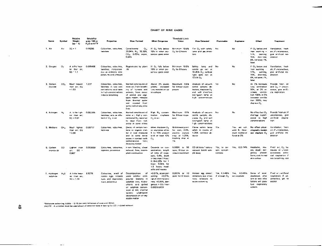
C H A R T O F MINE GASES
Symbol Relative Weight (ajr= 1)
Solubility g per 100 cc H 2 O a t 4 1 ° F
Properties
3. Carbon dioxide
4. Nitrogen
5. Methane C H 4
6. Carbon
monoxide
7. Hydrogen sulphide
A trifle heavier than air; S G = 1.1
Much heavier than air; S G = 1.53
A trifle lighter than air; S G = 0.97
Much lighter than air; S G = 0.55
Lighter than 0.003559
air; S G = 0.967
A little heav- 0.5276 ier than air; S G = 1.19
Colourless, odourless, tasteless
Colourless, odourless, tasteless; nonpoison-ous at ordinary temperatures and pressure
Colourless, odourless, tasteless in low concentrations; acid taste in high concentrations induces breathing
Colourless, odourless, tasteless; acts as dilu-tent of 0 2 in air
Colourless, odourless, tasteless
Colourless, odourless, tasteless, poisonous
Colourless, smell of rotten eggs; irritates eyes and respiratory tract; poisonous
How Formed
Constituents: 0 2 , 20.94%; N 2 , 78.09%; C 0 2 , 0.03%; argon, 0.94%
Regenerated by plant
Normal constituent of mine air; from breathing of humans and animals, from decay of animal and vegetable matter; released from thermal water and exuded from some rock strata; mine fires
Normal constituent of mine air; highly concentrated N 2 reported to issue from rock strata in some mines
Decay of certain bacteria or organic matter in coal measures and in some metal mines in contact with carbonaceous rock; decaying timber From blasting, diesel exhaust, fires, incomplete combustion
Decomposition of some sulphur compounds; blasting in sulphide ores; hydrochloric acid spilled on sulphide concentrate or ore; thermal waters; underwater decomposition of vegetable matter
When Dangerous
If 0 2 falls below 16% or when poisonous gases enter
If 0 2 falls below 16% or when poisonous gases enter
Above 2% causes greatly increased lung ventilation up to collapse
High N 2 concentration displaces 0 2 in air
When displaces 0 2
or explosive when 5 to 15% present with at least 12% 0 2
Depends on concentration, length of time of exposure; 0.4%, death in less than 1 hour; 0.15-0.20% for 1 hour; 0.04% for 1.5 hours; headache and nausea
+0.01%, acute poisoning; +0.07%, rapid unconsciousness; +0.05%, dangerous + 0.5 hour 0.002-0.003+
Threshold Limit Value
Minimum 19.5% 0 2 for 8 hours
Minimum 19.5% 0 2 for 8 hours
Maximum 0.5% for 8-hour expo-posure
Maximum 81% for 8-hour exposure
Withdrawal point for men, 2.5%; electric motors stop at 1.25%; blasting stop at 1%
0.005% or 50 ppm, 8-hour exposure maximum
How Detected
For 0 2 with safety lamp and gas detectors
Safety lamp and No candle go out at 16.25% 0 2 ; carbide light goes out at 12.5% 0 2
Analysis of vacuum No bottle sample; detectors; displaces 0 2
and will therefore extinguish lamp at high concentration
Analysis of vacuum bottle sample; displaces 0 2 and will extinguish lamp at high concentrations
Flame safety lamp when in excess of 1.25% methane detector
C O detector* canary Yes, in cer-vacuum bottle sam- tain concen-ple assay trations
Yes, see column 8; maximum explosive force at 9%
Yes, 12.5-74%
0.001% or 10 ppm for 8 hours
Rotten egg odour; detectors; eye irritat ion; subacute acute poisoning
Yes, 4.3-46% if enough 0 2
Yes, 4.3-45% will explode
to
If 0 2 below and man working — 17%, panting; 15%, dizziness; 9%, collapse; 7%, fatal
If 0 2 below and man working — 17%, panting; 15%, dizziness; 9%, collapse; 7%, fatal
A t 2% increases lung ventilation 50%; at 3% increases ventilation 100%; at 5% increases ventilation 300%; may displace 0 2
No effect but 0 2
shortage experienced in high concentrations
No effect physiologically except can displace 0 2
Headache, nausea, death; dangerous aftereffects; pink to red skin colour
Sense of smell deadened; after one or two inhalations will paralyse respiratory
Venti lation; fresh air; if unconscious, give artificial respiration
Venti lation; fresh air; if unconscious, give artificial respiration
Provide fresh air and 0 2 ; if unconscious, give artificial respiration
Provide fresh air; if unconscious, give artificial respiration
Venti lation; fresh air; if unconscious, give artificial respiration
Fresh air, 0 2 for nausea or unconsciousness; artificial respiration if not breathing; rest
Fresh air; artificial respiration if unconscious; get to doctor
system
'Subacute poisoning; 0.005 — 0.16 per cent irritation of eyes and throat. t N O T E : A scrubber must be used ahead of detector tube if testing for C O in diesel exhaust.

C H A R T OF MINE GASES (Continued)
Oxides of nitrogen
Symbol
N O
N 0 2
N 2 0 4
N 2 0 2
N 2 0 N 2 0 3
N 2 0 5
. Sulphur dioxide
S 0 2
10. Hydrogen H 2
11. Powder smoke
12. Aldehydes
13. Arsine (arsenous hydride)
14. Hydrogen cyanide acid; prus-sic acid
Relative Weight <air = 1)
Heavier than
air; S G = 1.59
Solubility g per 100 cc H 2 Oat 41°F
N 0 2 -0.007747
Much heavier than air; S G = 2.20
Lighter than air; S G = 0.0695
Highly sol-ble in water 16.80
(1) About same as air
Normal; same as air
About three times weight of air
Colourless in low concentration; reddish brown in high concentrations; odourless, tasteless, poisonous
Colourless, suffocating, irritating with strong sulphur smell, acid taste, poisonous
Colourless, odourless, tasteless
Smokey odour of nitrous fumes; irritates eyes; has C O and N 0 2
mixed in it; poisonous
How Formed
For blasting or burning of dynamite; diesel exhaust; burning or decomposition of nitrates or nitrated material
Blasting in or burning of sulphide ores; some diesel fuels may have appreciable sulphur present and will form S 0 2 on burning
Thermal water; battery charging; electrolysis of water; product of incomplete combustion in explosions and mine fires; corrosive action of strong acids on metal (iron)
Product of incomplete combustion during blasting
When Dangerous
0.01% may be fatal in 0.5 hour
400 ppm dangerous even for short exposure; 50 ppm subacute poisoning and irritation to eyes, throat, and lungs; 20 ppm irritating to eyes; coughing caused
No harmful effects
Threshold Limit Value
0.005% or 5 ppm maximum exposure at any time
0.0005% or 5 ppm for 8-hour exposure
How Detected
Odour of burning No sulphur; irritating to eyes and respiratory tract; detector
Laboratory analysis of gas sample; gives indication on detectors using Wheat-stone bridge resistance measurement
When C O , N 0 2 See Mines Act
content above ac- on use of explo-ceptable limit sives
Odour, colour of ni- Yes, if flam-trous fumes; C O and mable gases N 0 2 detectors present in suf
ficient quant-
Yes, 4.1-74% with as little as 5% 0 2 ; violently explosive 7¬8%
Yes, under certain conditions
ity
Irritates eyes and res- Diesel engine opera- 1 ppm — irritates 10 ppm for 8- Smell , eye irritation; piratory tract
Highly poisonous
Smell of bitter almonds; deadly poison
t ion; soluble in water; removed by water scrubber on diesel engine
Formed by reaction of hydrogen with arsenic; hydrogen may form with strong acid on metal and in presence of arsenic or arsenic compounds, e.g., mill circuit
Hydrochloric acid on sodium or potassium cyanide; may occur in mill areas where cyanide is used; produced during heat treating of drill steel; may be released from tailings where cyanide has been used for mineral recovery
hour exposure
10 ppm
0.05 ppm permitted; 1-10 ppm dangerous after 1 hour; 100 ppm dangerous to life
10 ppm
analysis of vacuum bottle; sample collected in special solutions
Mercury chloride filter paper test; detectors or by physiological effect
Smell of bitter almonds; detector
Gas — yes Gas — yes
Oedma of lungs; delayed effect
Irritating to eyes, throat, and lungs; produces oedma of lungs
None except may displace 0 2
Headache, dizziness, nausea, and throat irritation
Small concentrations, stinging of eyes
Destroys red corpuscles in blood; nausea; bronzing of skin; black-red urine; tightness of chest; slight delayed action; cumulative effect
Paralyses respiratory system developing chemical asphyxia; absorbed through skin as well as in lungs
Complete rest; give 0 2 ; see doctor and advise of man's exposure to oxides of nitrogen
Fresh air; artificial respiration if not breathing; get to doctor
Treat for low 0 2
Remove to fresh
air or give fresh air
or 0 2 ; if uncon
scious artificial res
piration; watch for
48 hours
Fresh air
Fresh air immediately; turn over to doctor; advise doctor of exposure if known
Fresh air; give cyanide antidote as directed; get doctor; special cyanide-type canister required; use mask nide-type canister with extreme caution

15. Mercury Hg Vapourizes when in liquid state
16. Propane C 3 H 8 1.56
17. Acetylene C 2 H 2 0.91
18. Chlorine C l 2 2.49
19. Ammonia N H 3 0.6
Gas inflammable; tasteless; colourless; odourless; scented commercially
Gas inflammable; col
ourless; distinct odour
Greenish yellow gas
Highly solu- Colourless; strong ble in water odour; caustic action
May occur as free metal in some Hg ores; produced by heating of Hg ore; used industrially as in production of Hg-Au amalgam
Petroleum distillate
Water on calcium carbide
Various ways chemically but principally from electrolysis of common salt
Combination of hy drogen nitrogen with catalytic action
Adheres to clothing and skin unless careful control is maintained, contamination might be cont inuous* *
Explosive
2.4-9.5%
Explosive range,
2.8-81%; tank may
explode on shock,
i.e., by dropping
pressure sensitive
above 15 psi
Above 1 ppm
Explosive when exposed to oxidizing substances and heat
0.1 mg/rrr self-contained equipment only; safe respiratory protection in areas of high concentration
range, 1 000 ppm
Physiological reac- No t ion; detector; analysis of vacuum bottle sample
Safety lamp; meth- Yes anometer
Odour detector
Excess flow of saliva, loosening of teeth; diarrhea; nervous and psychic changes
Corrosive irritant eyes, skin, lungs, etc.; use type ' N ' mask up to 2% concentration
Corrosive irritant to eyes, nose, throat, and lungs
Careful personal hygiene, body and clothing; no smoking nor eating in areas where Hg present; clean plant and spray with lime-sulphur spray
Venti lation; fresh air; if unconscious, give artificial respiration
Ventilation; fresh air; if unconscious, give artificial respiration
Complete rest; give 0 2 ; see doctor and advise man's exposure to oxides of nitrogen
Fresh air; rest
* * Keep plant clean.

52

INSTRUMENTS USED IN MINE-RESCUE TRAINING COURSE
The following instruments are used to determine the condition of mine air and the state of the ventilation.
FLAME SAFETY LAMP
The flame safety lamp is a device used for determining if the mine atmosphere will or will not support combustion or life, for detecting the percentage of methane gas, and for detecting the presence of excess nitrogen or black damp in mine air.
The lamp has four gauzes, burns naptha, and is magnetically or key locked. Magnetically locked safety lamps are the only permissible flame safety lamps to be used when flammable gases are present. The magnet to open such lamps must not be used in the presence of a flammable gas.
The air feeding the lamp enters through a double gauze below the wick and the gases of combustion from the lamp exit above the wick through double gauzes. These gauzes are constructed of steel wire mesh having 28 wires to the inch or 784 openings to the square inch. The hot gases of combustion in passing through the double gauzes are cooled or quenched by the mesh absorbing the heat from the gases. It is this cooling effect that forms the safety principle and allows the lamp to be used where combustible gases may be encountered. The combustible gases such as methane may burn within the lamp but the resulting flame will be cooled below the ignition point of the gas surrounding the lamp as it passes through the double gauze. However, the safety lamp is only safe when it is assembled correctly and used carefully by a competent person. The flame of the lamp must be kept fairly low at all times and the lamp removed when a large percentage of methane is encountered so that the gauzes do not overheat. The flame from burning gases within the lamp will pass through the gauzes when they become red hot thus being unable to absorb heat from the flame.
Flame safety lamps will not burn in a methane-free atmosphere having an oxygen content below 16.25 per cent, however, they will burn in atmospheres of lower oxygen content if methane is present. The lamp flame will be extinguished when the oxygen content falls below 13 per cent regardless of the percentage of methane present. Usually as the percentage of oxygen in the air approaches 16 per cent the flame will gradually lower, grow dim and flutter, then go out.
Methane gas, being flammable, will burn within the lamp and has the effect of increasing the length of the lamp flame. The elongation of the flame caused by the gas is a pale blue flame (cap) that appears to ride on or over the lamp flame. The height or length of the cap is indicative of the percentage of methane present. However, when testing for methane the flame in the lamp should be lowered until there is just a small yellow flame visible. This method will allow the blue cap of the burning methane to be more visible.
Approximate sizes of blue caps in relation to percentage of methane are:
• 1/3-inch cap represents 1.0 per cent methane.
• 3/8-inch cap represents 2.0 per cent methane.
• 1/2-inch cap represents 2.5 per cent methane.
53

CJ1 4*
c */>oet> <£-fii*><%
€«*
1 1 * 1
MS*
B T » P * A T • /*<•"
A I S S U E D
REV DESC INITIAL DATE
KOBHIBI* MANOMCTUWN* COMPANY M4.LIQNOUIH. MASSACHUSETTS 01TSS
TITLE
IGNITER ASSEMBLY DRAWING B 1 ° 257-30A

• 7/8-inch cap represents 3.0 per cent methane.
• 1-1/3-inch cap represents 4.0 per cent methane.
ANEMOMETER AND VELOMETER
These instruments are used in the determination of air flow for ventilation purposes.
An anemometer consists of a steel ring within which is posed a rotating vane, the blades of the vane are inclined to the plane of rotation. The air current striking the blades rotates the vane, the number of revolutions being recorded on the face of a dial by means of a series of gears. The instrument is so calibrated that each revolution of the vane corresponds to 1 lineal foot of air travel. It is employed to measure the velocity of the air current as expressed in feet per minute.
The design of a velometer is based on the pitot tube principle. Pressure exerted on a vane travelling in a circular tunnel causes a pointer to indicate the measured values on a scale, either in English units or metric units.
THERMOMETER
Moderate temperature is measured by thermometers, on either the Fahrenheit or centigrade scales. Thermometers consist of a thick glass tube with a small uniform bore, sealed at one end and terminating in a small bulb at the other end. This bulb contains mercury or alcohol; when the temperature rises the liquid expands and rises and when the temperature drops the liquid level drops.
Fixed points on the Fahrenheit thermometer are 32 degrees and 212 degrees Fahrenheit; 32 degrees Fahrenheit is freezing temperature and 212 degrees Fahrenheit is boiling point.
Fixed points on the centigrade thermometer are 0 degrees centigrade, freezing temperature, and 100 degrees centigrade, boiling point.
To convert centigrade to Fahrenheit, 9/5 x C + 32 = F. To convert Fahrenheit to centigrade, (F — 32) x 5/9 = C.
Examples:
Convert 60 degrees centigrade to Fahrenheit. 60 x 9/5 = 108 + 32 = 140 degrees Fahrenheit.
Convert 140 degrees Fahrenheit to centigrade. (140 - 32) x 5/9 = 108 x 5/9 = 60 degrees centigrade.
In the gram-metric measurement system adopted in Canada in 1978 centigrade and Celsius temperature readings are the same.
Two thermometers are used in the construction of an hygrometer, a device for determining the humidity of air. The thermometers are mounted side by side on a frame and the bulb of one is covered with muslin
55
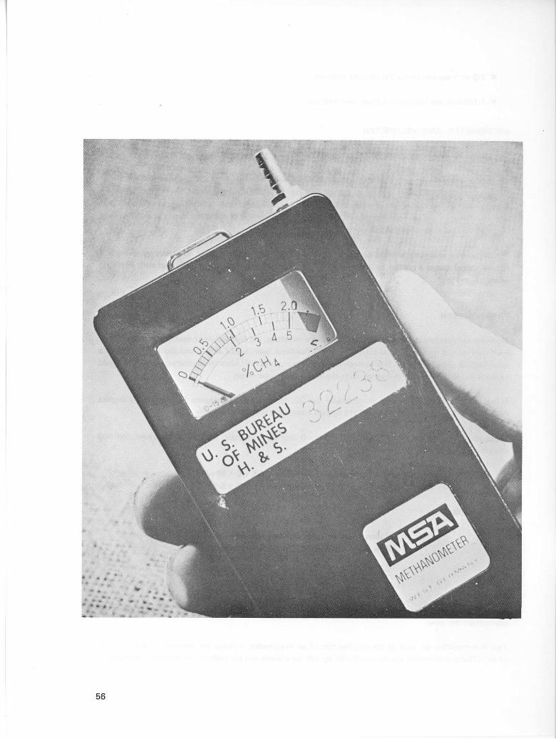
56

THE WHEATSTONE BRIDGE
1. Resistor Ri is the reference element. It is a fixed resistor, but its value will vary slightly with atmospheric temperature. It is mounted near the sensing element to compensate for atmospheric effects upon R x .
2. Resistor R 3 has a fixed value of resistance.
3. Resistor R x is the sensing element. Its resistance will vary according to some variable factor which will be measured.
4. Resistor R2 is a potentiometer, which has variable resistance. By the use of R2, we adjust the balance of the bridge until the meter reads zero. (This is electrical zero.)
5. When the bridge is balanced, there is no difference in potential between points A and C, thus no current through the meter and it will read zero.
6. At this time, the voltage drop across R x is equal to that of R2, and the voltage drop across Ri is equal to that of R 3 .
57

kept moistened with water. Evaporation from the moistened bulb produces a depression of temperature so that this thermometer reads lower than the dry bulb. The thermometers should be mounted so as to permit the free circulation of air around the bulbs. Usually the device is constructed so that it can be freely swung in the air being monitored in order that the thermometers will reach constant readings. The two readings are recorded and by reference to a chart or special slide rule the relative humidity of the air can be determined.
ELECTRIC CAP LAMP
The electric cap lamp is the safety lamp which is most commonly used by miners. It is a lamp in which the energy necessary to provide electricity for the light is stored in a chemical form in the cells during charge and is released by chemical action during discharge.
The principal safety feature of the electric cap lamp in a methane concentration is the spring supporting the light bulb. In the event the light bulb is broken, the spring automatically breaks the electrical circuit.
OXYGEN DETECTOR
In 1966 a new type of polarographic electrode was developed by the Safety in Mines Research Establishment in Great Britain. This instrument is capable of determining the amount of oxygen present in a sample of gas being tested. The apparatus is an electrolytic cell having a lead anode and a cathode made of a membrane of either teflon or silicone rubber metallized on one face with a layer of gold overlain with a layer of silver. The oxygen in the sample diffuses through the membrane to the cathode and an electric current is produced the magnitude of which depends on the amount of oxygen present. Instruments based on this electrode are insensitive to shock, orientation, air velocity, and to other gases generally found underground. The instrument should not be used in atmospheres containing oxides of nitrogen or where it is possible to coat the membrane with oil or similar material. This equipment has several models available but most notably with the following ranges of oxygen:
• 0 per cent — 25 per cent.
• 0 per cent — 40 per cent.
• 0 per cent — 100 per cent.
• 0 per cent — 50 per cent and 0 per cent, 100 per cent monitor.
The time required to make a test is between 20 and 30 seconds with an accuracy of ± per cent if the instrument is at ambient temperature.
METHANE DETECTORS
Several electrically operated methane testers are available some of which pump either mechanically or manually the gas sample being tested, while others rely on infusion of the gas sample through a porous fitting. All operate with a Wheatstone bridge circuit which has one of the four balanced resistance paths
58

of the bridged circuit passing through the burning chamber. The burning gas causes an increase in the amount of heat in the wire and this causes a change in resistance which varies with the heat generated or the amount of combustible gas present. The circuit imbalance is represented by a meter reading calibrated to indicate the percentage of methane in the atmosphere. Ministerial experience indicates that the porous head detectors can give low readings where there is an appreciable ventilating current. This is caused by the cooling effect of the circulating air.
TESTING DIESEL EXHAUST
Where diesel motors are used in mining operations it is necessary that frequent tests be made to check the amount of carbon monoxide in the exhaust gases. A scrubber, filled with gasorbent, is available and should be attached to the inlet of the instrument. The gasorbent prevents the passage of all gases except carbon monoxide, which would have an effect on the silica gel. Readings may then be taken in the regular manner. Samples should not be taken directly from the exhaust manifold, as hot gases will cause errors in the result.
DRAEGER GAS DETECTOR
This instrument consists of a spring-loaded rubber bellows with a capacity of 100 cubic centimetres of air, and a replaceable indicating tube. Air to be tested is drawn directly into the indicating tube before passing into the bellows, and thus the instrument requires no purging before inserting the tube. The outlet valve of the bellows provides so little resistance that the air will not return through the testing tube.
The Draeger gas detector is designed for the testing of a number of gases, using various indicating tubes. Although indicating tubes are available from different sources, only Draeger tubes are to be used with the Draeger tester, otherwise serious errors could occur in the test readings. We are concerned here primarily with the testing of carbon monoxide.
Different types of indicating tubes are available for testing of low and high quantities of carbon monoxide. The low-range tubes are used in testing carbon monoxide from 10 to 3 000 ppm (0.001 to 0.3 per cent). The high-range tube, identified by the yellow band, is used for testing carbon monoxide from 0.3 to 4 per cent. All tubes contain filtering chemicals to remove hydrocarbons and other gases that could affect the reading on the instrument.
INSPECTING THE DETECTOR BEFORE USE
The bellows should be squeezed once or twice to be sure the outlet valve is operating. Then place a finger over the inlet and collapse the bellows. The bellows should remain collapsed unless the outlet valve is leaking. It is not necessary to check the time taken for the bellows to inflate, as that action is controlled by the resistance built into each indicating tube. If the outlet valve is leaking, the valve cover plate may be removed and the valve seat inspected or cleaned.
USE OF THE DETECTOR
To use the detector, select the proper carbon monoxide-indicating tube, depending on the concentration of carbon monoxide that may be expected due to conditions that are known. Break the sealed ends of the
59

A
Fig. 1 Multi G a s Detector ready for use 2i6$2
60
The D R A G E R Mul t i G a s Detector , ready for use, cons is ts of two par ts :
T H E G A S D E T E C T O R P U M P and the
D R A G E R T U B E chosen as a function of the measuring problem involved.
Pump and tube together form one unit in the measurement. The DRAGER tube is the indicating instrument of the Multi Gas Detector.
The unit is supplied in a metal carrying case. A protective bag for the pump and spare parts are also supplied with the unit.
Accessories for the DRAGER Multi Gas Detector:
1. Pump stroke counter
2. Extension tube (3 m long), with bag, for sampling at inaccessible points
3. Hot air probe for the investigation of furnace waste gases
4. Supplementary part for the respiratory CO test
5. Motor vehicle exhaust probe for the investigation of exhaust gases
6. Mixing device
7. Dust sampler.
The advantages of the D R A G E R Mul t i G a s Detector a re :
• Opera t ion with one hand
• Low weight and s imple operat ion
• A lways ready for use
• D R A G E R tubes for about 100 different gases and vapours
• Pr inted measur ing sca le on the D R A G E R tubes
• Immediate reading of the resul t on the D R A G E R tube.
• Op t imum accu racy of measurement
• Main tenance- f ree bel lows pump

indicating tube by inserting them in the 'breaker' attached to one end of the drag chain on the bellows. Insert the tube firmly into the detector inlet so the passage of air will be according to the arrow on the tube, squeeze the bellows fully to expel the residual air, and then allow the bellows to refill completely. If the air sampled contains carbon monoxide, a dark stain will be noticed extending downwards through the white crystals. The percentage is measured according to the distance the stain extends into the crystals. The reading is taken at the lowest level of the general discolouration, and not at the deepest point of colour penetration.
All tubes have a band on the upper end on which can be written data concerning the test. Tubes once coloured will not change colour for several hours, and so may be read later under better lighting conditions than found in testing areas underground. Tubes that have been used and no colour reaction obtained may be reused up to 10 times, or until colour is found, in 1 day. Once coloured they must not be reused.
When testing diesel exhaust or other high mixtures of hydrocarbons for carbon monoxide, a carbon pre-tube filled with activated charcoal should be used as an additional filter to prevent the hydrocarbons from reaching the testing crystals. Exhaust gas should not be sampled directly from the manifold, but should be passed through some form of cooler to bring the temperature into the range of 50 to 112 degrees Fahrenheit.
The example described above is based on testing for carbon monoxide. Since this apparatus is a multi-gas detector a wide range of detector tubes are available for different contaminants. Each gas and its indicating tube has its own characteristic and method for use, making it impossible to have a working knowledge of how to use them all. This is not a problem for in each new box of tubes is a data sheet which contains all the information needed to make a test with the type of tube to be used; therefore, it is important that anyone using a multi-gas detector should know how to read the data sheet:
COMMON APPLICATIONS OF THE DRAEGER MULTI-GAS DETECTOR
1. For controlling the threshold limit values of contaminated air in work areas.
2. Testing tanks, sewers, and manholes before entry.
3. For tracing leaks in gas pipes and reservoirs.
4. In detecting gas losses in certain types of processes such as recovery plants, etc.
5. Identifying unknown gaseous contaminants by using different detector tubes.
6. Measuring the hydrogen sulphide in refinery gases and sewage disposal plants.
7. Controlling carbon dioxide concentrations in greenhouses, fermenting rooms, grain silos, fruit storage rooms, and testing for leaks in carbon dioxide extinguisher systems.;
8. Measuring the carbon dioxide content in flue gas or forklift and vehicle exhaust gases.
9. Adjustment of the fuel injection pump for diesel engines.
10. To rapidly diagnose the percentage of carbon monoxide in alveolar air or in samples of blood.
61
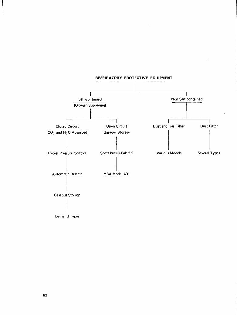
RESPIRATORY PROTECTIVE EQUIPMENT
Self-contained
(Oxygen Supplying)
i Non Self-contained
Closed Circuit
(C0 2 and H 2 0 Absorbed)
Open Circuit
Gaseous Storage
Automatic Release
Gaseous Storage
Demand Types
MSA Model 401
Dust and Gas Filter Dust Filter
Excess Pressure Control Scott Presur-Pak 2.2 Various Models Several Types
62

CHEMISTRY OF FIRE
DEFINITION
Fire or burning may be described as a form of rapid oxidation of a substance and is accompanied by a large release of heat and light energy (the release of heat energy may be so rapid as to cause a violent expansion of the gases produced which is described as an explosion).
In examining this definition it will be seen there are three requirements necessary for a fire and these are:
1. Oxygen to provide oxidation.
2. A fuel or a substance which will burn.
3. The production of heat energy.
These three items become the components of the triangle of fire, and the absence of any make a fire impossible.
OXYGEN
This is a colourless, odourless, and tasteless gas which supports combustion. Ordinary air contains about 21 per cent oxygen.
Oxidation is the chemical combination of oxygen with another element or compound. This combination is almost invariably accompanied by a release of heat energy. Such a release is known as an exothermic reaction. The amount of heat energy released varies with the elements or compounds with which oxygen combines. Among the highest heat energy releases are those occurring when oxygen combines with carbon, hydrogen, or a compound of both elements.
If the chemical combination with carbon and oxygen is complete carbon dioxide, a colourless gas, is produced. If the combination is with hydrogen and oxygen, water vapour or steam is produced. If the combination includes both carbon and hydrogen and the reaction is complete, then carbon dioxide and water vapour are produced and the resulting smoke is white. If the reaction is incomplete, the products of combustion are carbon monoxide, carbon dioxide, water vapour, and particles of free carbon which form grey or black smoke.
63

FUEL
The fuel is any substance, solid, liquid, or gas which, with an adequate supply of oxygen, will burn. However, the speed of ignition is not necessarily related to these physical states but to a number of conditions such as:
• Physical size of burning material (for example, dust, lump, or gaseous).
• Concentration of flammable vapour.
• Supply of oxygen.
• Available heat.
• Ignition temperature.
• Flash point with liquids or gases.
The ignition temperature is defined as the temperature at which a substance can be ignited and will continue to burn spontaneously (that is, the heat generated by the ignition is sufficient to maintain burning). Flash point is that temperature at which a flammable liquid gives off vapours sufficient to form an ignitable mixture with air.
As mentioned earlier ignition can be accompanied by explosive force. Certain fuels have in their vapour states a broad concentration range (explosive limits) where an explosion will occur if ignition takes place within the range. The explosive limits are expressed as a percentage by volume of a mixture of the particular fuel with air.
Some examples of the explosive limits, flash points, and ignition temperatures are as follows:
Fuel
Acetylene Carbon monoxide . . Ether Gasoline Lube oil Methane No. 1 fuel (stove oil) . Propane
Explosive Limit
per cent
2.5^81 12.5-74
1.948 1.4- 7.6
5.0-15 0.7- 5 2.2- 9.5
Flash Point ° F
- 49 -45
300-450
100
Ignition Temperature
°F
571 1 128
356 536
500- 700 1 202
900-1 070 871
Flammable liquids are classified into three groups according to the temperature range of their flash points and are listed as follows:
1. Class I — 20 degrees Fahrenheit or less.
2. Class 11—21 degrees to 70 degrees Fahrenheit.
3. Class 111 — 71 degrees to 200 degrees Fahrenheit.
64
HEAT
The source of heat for commencing ignition is usually from an external source, however, once commenced the amount of heat released during ignition is frequently sufficient to maintain ignition spontaneously.
In addition to heat released in the oxidizing process of burning, the following conditions may cause ignition or may increase the available heat:
• Friction — an overheated bearing or the striking of a match.
• Electric flow (a) static spark discharge — resistance to current flow produces heat. (b) overheated current-carrying wire — resistance to current flow.
• Chemical generation — spontaneous combustion, for example, oily rags, metallic sodium.
• Conduction — transfer of heat energy via an overheated metal rod.
• Convection — circulation of overheated air.
• Radiation — overheating by sunlight or from a nearby fire.
CONTROL
If adequate quantities of the three elements of the fire triangle are present then a fire is waiting to happen. If the fire has started it will surely be nourished unless one or more of the elements are removed. Although it may be possible to remove or isolate the fuel as a wise fire-protection act, the most common combatant procedure is to reduce the temperature by quenching or by cutting off the oxygen supply. On type 'A' fires such as the free burning of wood, rubbish, textiles, paper, etc., extinguishing can be done by cooling and quenching with type 'A' extinguishers which are soda-acid, pressurized pump tank, foam, or water. On type 'B' fires, which include such volatile quick-burning fuels as gasoline, oil, or ether, type 'B' extinguishers which are C O 2 , dry chemical, or vapourizing liquids should be used. These extinguishers blanket or smother the fire by displacing the oxygen. When such extinguishers have been used in closed or sunken areas great care must be taken not to have the fighter asphyxiated. Class ' C fires are electrical and require nonconductant type ' C extinguishers which are C O 2 , dry chemical, vapourizing liquid, or chloro-bromomethane (CBM). A fourth type of fire extinguisher has been evolved in recent years and that is the use of foam. The foam is blown into the fire area and extinguishes it by cutting off the oxygen and the moisture present helps quench the flame.
All mine-rescue teams should become thoroughly familiar with the different types of hand-operated extinguishers in use at their operations and receive hands-on training on how to correctly use them.
Fire fighting or fire brigade training is a course in itself and for this reason it is not extensively covered in this mine-rescue course.
65


Know your ABCD's of...
Extinguishers National Fire Protection Association, 60 Batterymarch St., Boston, Mass. 02110 designed by Dray Publications Inc.
67

WHAT'S To Extinguish:
. BURNING? jp^P^L • 4 " C L A S S E S - — cact i ex t ingu ished d i f ferent ly

COMPACT DEVICE... CARRYING HANDLE
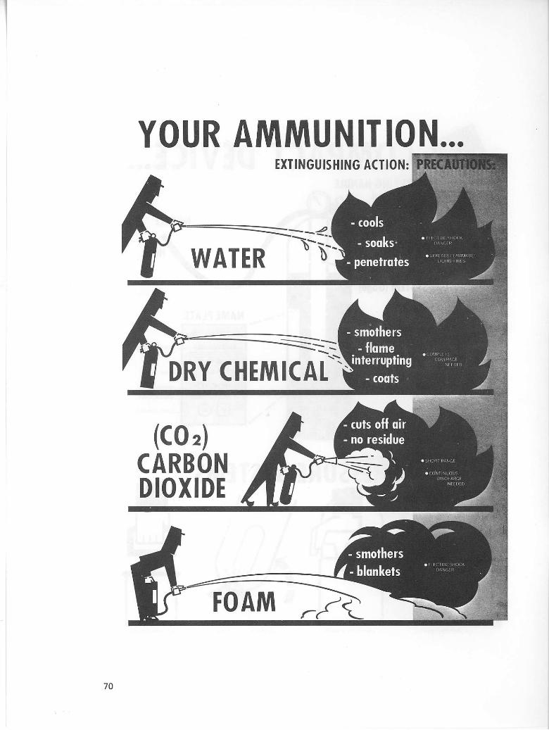
YOUR AMMUNITION... EXTINGUISHING ACTION: PRECA
- c o o l s
WATER - s o a k s -
p e n e t r a t e s • SPRI ADS i i.ammabl:
DRY CHEMICAL
(CO 2) CARBON DIOXIDE
/ - b l a n k e t s • TL tC IF f lC S H O C K
DANGER
FOAM
70

4 Pressure System5
• S tored Pressure • Car i r i dge Opera ted • C h e m i c a l Reac t ion • Hand P u m p
A Con ten ts
• Water Type • Dry C h e m i c a l (Regular . Mul t i -P i i rpose) A Ca rbon Diox ide • F o a m
NEEDED... .YOU to take the RIGHT ACTION
at the RIGHT TIME!!! So lei 's look at how to use each type ex t ingu ish?
71
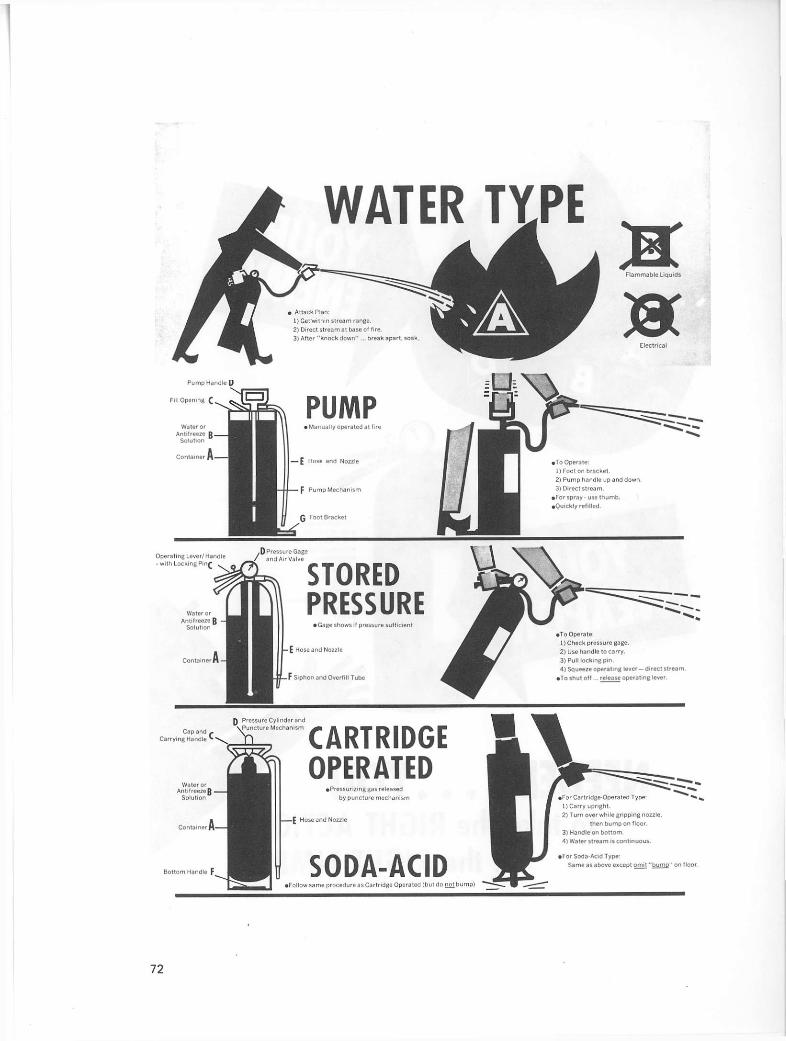
WATER TYPE
C a p Ca r r y i ng
Bo t tom Handle F
72

Pressure Gage D
C o m b i n a t i o n Opera t ing
Lever /Hand le — with Q
DRY CHEMICAL TYPE • Mu l t i -Purpose Dry C h e m i c a l :
-effective on " C l a s s e s A , B a n d C '. e i c e p t s o m e under 5 lbs. not " C l a s s A " rated
STORED PRESSURE • Gage shows iI pressure suf f ic ient
E Hose and Nozzle
F l a m m a b l e L iqu ids
F S iphon Tube
• To Operate: 1) Keep upr ight .
2) Remove lock ing p in . 3) Squeeze opera t ing lever
whi le d i rec t ing s i r e a m .
( S o m e models have d i scharge con t ro on ex t ingu isher valve assembly . ]
H o s e a n d Squeeze-Gr ip r\
Fil l C a p D
Car ry ing Handle C
CARTRIDGE OPERATED
• P ressur i z ing gas released
by punc ture m e c h a n i s m
F Punc tu re Lever
G Pressure Car t r idge • To Operate:
1) Keep upr ight. 2) Remove lock ing p in
3) Press punc tu re leve 4>Saueeze lever on no
d i rec t ing st t l.i
73

CO, TYPE (Carbon Dioxide)
• A t tack P l a n : D S e t c lose — l imi ted 2) Con t i nue af ter ex t i ngu ishment
to prevent re f lash,
For " C l a s s B " — 1) Beg in at near edge. 2) At tack ent i re ( ront — then progress
a c r o s s b u r n i n g su r face to avoid being " f l anked 3) Marnta in fu l l d ischarge rate. Fo r " C l a s s C " — 1) A i m d i rec t ly in to base of f i re. ' 2) Shu t off power as soon as poss ib le . ( U s e c a u t i o n in con f ined p laces — lack of oxygen. )
Ord inary C o m b u s t i b l e s
— not effect ive except
Ia n v e r y s m a l l f i r e s -needs fol low-up wi th water.
STORED PRESSURE l iquid form — under pr
E Hose or Tube and Discharge Ho
i To Operate: D K e e p upr ight.
2) Pu l l l ock ing p in .
3) Squeeze opera t ing lever /hand le — d i rec t d i scharge at base of fii (avoid c o n t a c t w i t h horn)
74

ON FLAT FOAM TYPE
Inner Conta iner wi th F o a m Act iva t ing and Pressur iz ing So lu t i on
Water So lu t i on with Foam Concen t ra te
75

f l R E J • No P a n i c - N o Wrong Move - Seconds Coun t . P lan Now.
. . . ALARM • Everyone o u l — cal l f i redep t . . . don' t torget (even if sma l l ) .
. . . . ACTION • II sti l l sma l l , l igh t it... first m o m e n t s v i ta l .
Even one ex t ingu isher may prevent d isas ter . . . II f ight ac t i on ! * What 's b u r n i n g ? - Ord inary C o m b u s t i b l e s IA1 - use Water type or Mu l t i Pu rpose Dry C h e m i c a l .
- F l ammab le L iquids (B) - use Dry C h e m i c a l . F o a m . C a r b o n Diox ide (no water). - Electr ica l IC) • use Dry C h e m i c a l . Ca rbon Diox ide |no water or l o a m it power on). - C o m b u s t i h l e M e l a l s t D l - use per local ins t ruc t ions lor par t i cu la r meta l .
. . . . AFTER C h e c k lor s m o l d e r i n g C h e c k penet ra t ion into cei l ings, par t i t ions, f loors . Have f i re dept. check . Replace exhngi j is t ier — never put back if part ia l ly used.
C o n c l u s i o n : Por tab le l i re ex t ingu ishers are l i rst l ine o ' l i re de fe r Prep lan lor fire in your a rea , Quick , cor rec t ac t ion c a n prevent fire d isaster . IT'S IN Y O U R H A N D S !
ESCAPE AND RESCUE FROM BURNING BUILDINGS
RESCUE
GENERAL
The primary duty of mine rescue is to save life. Due to fear and excitement persons trapped often forget the normal means of escape and have a tendency to throw themselves from a window or roof into the street, despite the fact that there may be no immediate danger and that help may be at hand. Where persons are crying out for help, they should be reassured and told not to jump. Find out as quickly as possible whether anyone is trapped; this information can often be obtained from neighbours. If it is suspected that anyone is still in the building, a thorough and methodical search must be carried out at once.
No hard and fast rule can be laid down as regards rescue, as it depends entirely upon the type of building and equipment available. The general rule is that the search should begin at the top of the building so that the searchers are nearest to fresh air and safety at the end of their search.
ENTRY
When trying to enter a building the main door should first be tried, it may not be locked. If entry has to be forced, it should be done by the method which will cause least damage, remembering it is easier to break glass than wood. The possibility of entry by the back door should not be overlooked. The way the smoke issues from the opening will let the rescuer know whether there is gas building up. If it comes out in a gentle flow a gas buildup is not likely, but if it comes out in puffs one would suspect a gas buildup.
SEARCHING A BUILDING
When possible, it is advisable to work in pairs on entering a smoke-filled room or building. This gives confidence and makes it possible for one to assist the other. People trapped by fire or smoke often take refuge under benches or in cupboards where they hide to escape the smoke and flames. Searching, though swift, should be thorough, every room should be investigated, and no possible hiding place, however unlikely, overlooked.
SEARCHING A ROOM
Searching a smoke-filled room is not an easy task and is unlikely to be successful unless carried out on a definite plan. Once inside the room a complete circuit should be made, keeping close to the wall, feeling under and around objects, and opening and feeling inside cupboards and around objects and other articles of furniture. Finally, the room should be crossed diagonally to make sure no one is lying in its centre.
Always remember that floors immediately above the fire may have been weakened sufficiently to become dangerous and care should be exercised when it is necessary to search the centre of the room. Whether or not the windows should be opened to obtain fresh air during the search depends on circumstances. Only when it is known that the fire is in a distant part of the building and is being attacked, or if the atmosphere is cool, is it safe to open the windows.
77

When opening a door behind which fire may be found, the possibility of a back draught of flame caused by the intake of air should not be overlooked. The most obvious warning of danger is the presence of heat. The metal shank connecting the two door knobs is a very good conductor of heat and if this or the door knob prove to be very hot then the door must be opened with care. A room should not be entered, except for rescue purposes, without proper equipment for the immediate application of water to the fire.
If the door opens toward you then the foot should be placed against the bottom of the door and the handle turned gently.
There may be considerable pressure in the room due to the expansion of the heated gases. It is desirable to crouch in such a way that any heated gases or flames which are released pass over the head.
MOVING AN INSENSIBLE PERSON
It is not an easy matter to lift an insensible person and carrying involves the maximum danger in smoke, both from suffocation and falling. To move an insensible person turn him on his back on the floor, tie his wrists together, kneel across him, and place your head through the loop formed by his arms, then you can crawl on hands and knees dragging him with you although he may be far heavier than yourself. To move an insensible person downstairs lay him on his back, head downward on the stairs, place your hands under his armpits so that his head rests on the crook of your arm, and ease him gently downstairs.
78

GAS CONTROL
Ventilation is not a serious problem around surface or open-pit operations, but nevertheless every year workers are killed or injured because of dangerous amounts of gases or vapours, or because of not enough oxygen in places where they work. Such places, which are called confined spaces, include buildings, manholes, tunnels, vaults, chemical tanks, oil tanks, storage bins, silos, and pumps, etc.
There are several types of hazards that may be found in confined spaces:
• Toxic gases or vapours — gases that poison.
• Flammable gases or vapours — gases or vapours that ignite easily.
• Asphyxiant gases — gases that cause suffocation.
• Lack of oxygen.
Most people who expose themselves to a dangerous atmosphere are not aware the danger could exist or of the need to protect themselves. In an area where a dangerous atmosphere exists the hazards can best be taken care of by proper and adequate ventilation (the exception to this rule is when a fire is involved).
If a surface-rescue team cannot ventilate an area and lives or property are involved, proper respiratory equipment must be worn. This is why we feel a rescue team should be trained in the use of self-contained breathing apparatus.
To control gases on a property, supervisors and rescue teams should be made aware of any special gas-producing chemicals used on their property and should be able to test an area to see if it contains a dangerous atmosphere.
There are various methods and devices in use for detecting the presence and quantity of toxic, noxious, and explosive gases. The presence of carbon monoxide and deficiency of oxygen are the greatest hazards in rescue or recovery work, but the chance of encountering other gases make it necessary to train in the use of at least two of the following detectors:
• The multi-gas detector (Draeger or MSA).
• Flame safety lamp.
• Oxygen detector.
• Methane detector.
79
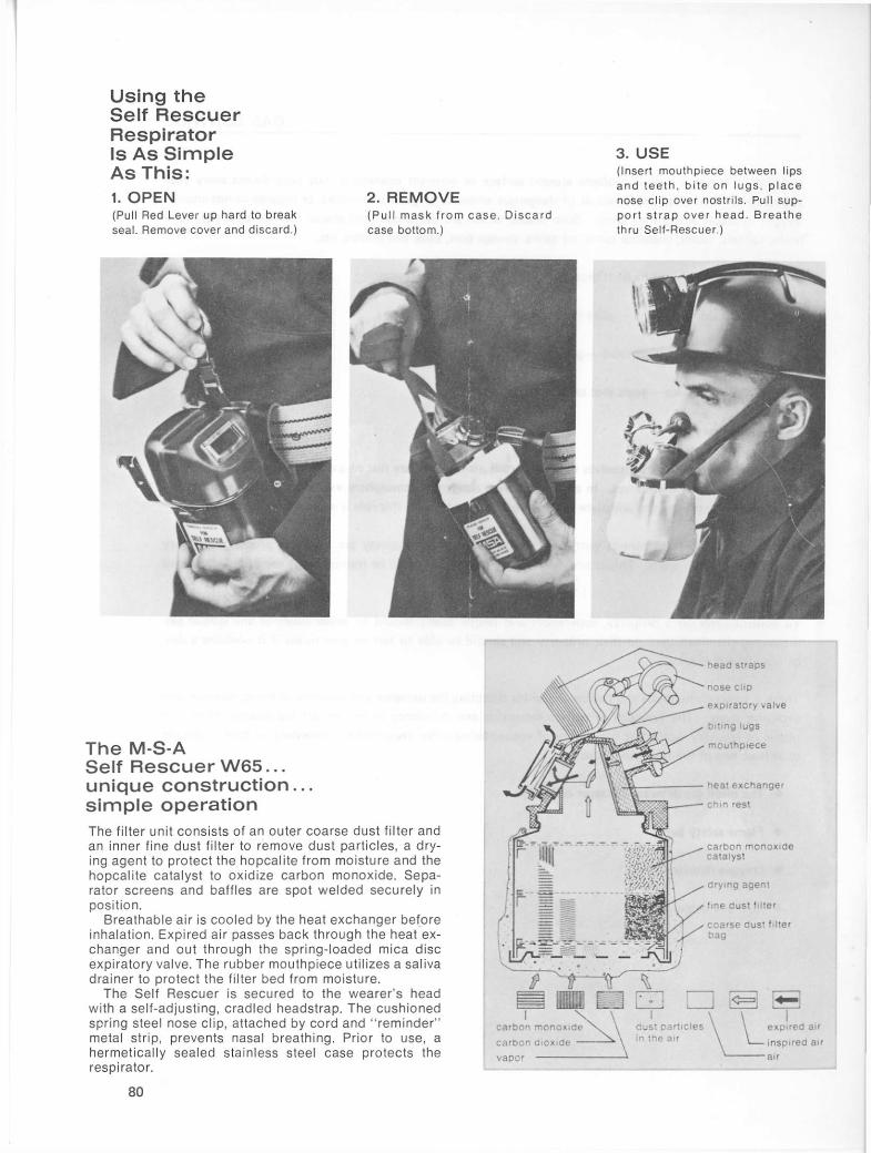
Using the Self Rescuer Respirator Is As Simple As This: 1. O P E N (Pull Red Lever up hard to break sea l . Remove cover and discard.)
2. R E M O V E (Pu l l m a s k f rom c a s e . D i s c a r d case bottom.)
3. U S E (Insert mouthpiece between lips a n d t e e t h , b i te on l u g s , p l a c e nose c l ip over nostri ls. Pul l suppor t s t r a p o v e r h e a d . B r e a t h e thru Sel f -Rescuer . )
The M-S-A Self Rescuer W65... unique construction.. . simple operation The filter unit consis ts of an outer coarse dust filter and an inner fine dust filter to remove dust part icles, a drying agent to protect the hopcal i te from moisture and the hopcal i te catalyst to ox id ize carbon monoxide. S e p a rator screens and baffles are spot welded securely in posit ion.
Breathable air is cooled by the heat exchanger before inhalation. Expi red air passes back through the heat exchanger and out through the spr ing- loaded mica d isc expiratory valve. The rubber mouthpiece uti l izes a sal iva drainer to protect the filter bed from moisture.
The Self Rescuer is secured to the wearer 's head with a self-adjust ing, cradled headstrap. The cush ioned spring steel nose cl ip, attached by cord and " reminder " metal strip, prevents nasal breathing. Prior to use, a hermetical ly sealed stainless steel case protects the respirator.
h e a d s t raps
n o s e Cl ip
exp i ra to ry va lve
b i t ing l u g s
m o u t h p i e c e
heat e x c h a n g e r
Ch in rest
c a r b o n m o n o x i d e
c a r b o n d i o x i d e
v a p o r
80

FILTER-TYPE SELF-RESCUERS
The filter-type self-rescuer is a small gas respirator designed to provide protection to the wearer against carbon monoxide gas which is usually present in the air following a mine fire or explosion.
Owing to its small size the filter-type self-rescuer may be easily carried on the worker's belt as is the case with coal miners, or it can be carried on the machine the worker is operating. It can, therefore, be readily available in the case of emergency.
Filter-type self-rescuers are also commonly stored in caches in strategic locations at mines so as to be readily available in case of emergencies.
There are two models, the Draeger Model 810 and the MSA Model W65. Both the Model 810 and the Model W65 self-rescuers are sealed at the factory and these seals should not be broken unless the self-rescuer is to be used. Once the seal is broken the chemicals in the apparatus can deteriorate and render the apparatus useless to the wearer.
The Model 810 is sealed in a vacuum while the Model W65 is sealed under pressure in the inert gas nitrogen.
Miners should always examine their self-rescuers for dents or other external damage before being used. If the seal is broken or the container damaged, do not use it. It should also be checked and weighed once every 6 months or more often.
Although there are slight variations in design, both the Model W65 and the Model 810 operate on the same principle.
When the wearer inhales through the mouthpiece, air is drawn in through the bottom of the self-rescuer and passes through the coarse dust filter bag which encloses the lower part of the apparatus. Coarse dust is removed by this bag. The air then passes through a fine dust filter in the bottom of the canister and through a drying agent. This drying agent removes excess moisture from the air which could reduce the effectiveness of the apparatus.
After passing through the drying agent, the air flows through a chemical called Hopcalite which changes the deadly carbon monoxide gas to relatively harmless carbon dioxide. The air containing the harmless amounts of carbon dioxide is then breathed by the wearer after having its temperature reduced by a heat exchanger.
When exhaled the air again passes through the heat exchanger and out through a check valve to the outside air. The check valve allows air to pass outward through it but will not allow air to come in from the outside. All inhaled air must pass through the canister and is treated before it reaches the wearer's lungs.
The filter-type self-rescuer is a very simple apparatus.
PROTECTION PROVIDED BY THE F ILTER-TYPE S E L F - R E S C U E R
The filter-type self-rescuer will protect the wearer against a 1-per-cent carbon monoxide concentration (10 000 ppm) for up to 1 hour, providing there is enough oxygen present to support life.
81

(illustr. 3) is now available for the first time in plastics with a new type of vacuum closure. The can part and the lid part are pressed together firmly and tightly by the action of a strong internal vacuum. The closure force holding the two parts together is approximately 70 kp (154 lbs.). The protection afforded to the filter and its mouthpiece by the container is exceptionally good. To open the plastics container in an emergency, the tear-open tab is pulled up (illustr. 4): air can then flow into the container, so that it can be immediately opened. The filter can then be taken out.
Component (c):
In case of emergency it must be possible to take hold of the filter sel f-rescuer without delay and to put it on quickly. It should therefore always be carried and not laid down, not even at the working place. This purpose is served by the carrying pouch (illustr. 5) which can be fastened to the lamp strap or to the belt. The carrying pouch is of soft, rubberlike plastics. It enables the filter self-rescuer to be carried in comfort and ensures that it is always readily available in every situation.
10
1 Nose c l ip 2 Mouthpiece 3 Head harness 4 Bits 5 A i r passage 6 Chin support 7 Exhalation valve 8 Mouthpiece casing 9 Coarse dust-filter
10 Filter 11 Container cover 12 Container canister
28196a
3 Principal components of the FSR 810 filter self-rescuer
Tear-open tab of the plastics container Carry ing pouch
27 398
82

Protection is provided against higher concentrations of carbon monoxide for shorter periods of time. However, the heat buildup in the apparatus is quite rapid for higher concentrations. There is always a certain amount of heat buildup of the air and this is an indication that carbon monoxide is actually present, and the more carbon monoxide that is present the hotter will be the air breathed.
In spite of heat buildup the self-rescuer must be kept in the mouth until fresh air is reached. Death from carbon monoxide poisoning can be swift and is more permanent than the discomfort caused by breathing hot air.
It is important to remember that a heat buildup in the air can be expected when using a self-rescuer in an atmosphere containing carbon monoxide. The hotter the air the more carbon monoxide is present and the more important it is to continue using the apparatus.
When mounted on moving equipment or carried by workmen, the self-rescuer has a service life of 5 years provided the seal is not broken. The date when the self-rescuer is put into service must be recorded on the self-rescuer itself.
When placed in properly constructed caches, the shelf life is indefinite. A properly constructed cache should be moisture proof, as moisture will seriously affect the life of a self-rescuer.
WHEN THE S E L F - R E S C U E R IS USED
The self-rescuer should be used immediately at the first indication of a fire or explosion even though no smoke is visible.
Waiting until smoke is visible could well prove fatal because the area could be filled in advance of the smoke by a lethal concentration of carbon monoxide. Smoke may not appear at all.
Use the self-rescuer at the first indication of a fire or explosion and keep it on until fresh air is reached.
USE OF THE S E L F - R E S C U E R
The first step in using a self-rescuer is to break the seal by raising the lever on top of the case. The cover is then removed and the self-rescuer is removed from the container. The mouthpiece is inserted in the mouth with the grip held between the teeth and the flange placed firmly between the teeth and lips to form a good seal. The nosepiece is then placed firmly over the nose so that the wearer is forced to breathe through his mouth. The head strap is placed over the head to support the weight of the self-rescuer. When wearing the self-rescuer there must be sufficient oxygen to sustain life (16 per cent by volume).
83

SELF-CONTAINED SELF-RESCUERS
At least two self-contained self-rescue units have been manufactured for rescue purposes in mines. Among these are the units produced by the Auer and Draeger companies in West Germany.
The Auer self-rescuer is a miniature chemical oxygen-producing unit with a quick-start canister. It provides a 45-minute supply of oxygen. The oxygen is quite hot inasmuch as the compactness of the unit does not allow for cooling .
The Draeger rescuer OXY—SR is supplied in two units which are the same except for the oxygen release valve. The OXY—SR 45 has a push-button valve which can be operated once only. It supplies oxygen from the small storage tank pressurized to 4,410 pounds per square inch for a 45-minute period at a flow rate of 1.2 litres per minute. This must be returned to the factory for replacement of the push-button valve.
The OXY—SR 30 has a hand-operated valve control and can supply oxygen for 30 minutes at a rate of 1.5 litres per minute. This unit can be recharged by means of an oxygen cascade system and high-pressure pump.
Both models may be supplied with mouthpieces or face masks. When mouthpieces are used a pair of goggles should be packed within the carrying case lid. A complete unit with case weighs approximately 5 pounds.
DESCRIPTION AND FUNCTION
The impact-resistant plastic casing and cover contains the oxygen cylinder, working pressure 300 atmospheres (atm), refillable soda-lime canister, folded up breathing bag with pressure-relief valve, high-pressure control valve with 1.5 litres per minute constant flow and lung demand regulator, corrugated breathing tube with mouthpiece and nose clip, or optional full facepiece.
With cover open, mouthpiece and nose clip fitted, and cylinder valve open, the required oxygen supply is maintained by the constant flow unit and the lung demand regulator. The operation of the latter is most essential as it fills the breathing bag in the first seconds of use.
The expired air passes through the breathing tube into the soda-lime canister where the carbon dioxide is absorbed. The respirable air flows on into the breathing bag where oxygen from the constant dosage unit is added. On inhalation, the air flows via the double nonreturn valve and the breathing tube to the mouthpiece. The OXY—SR self-rescuers are thus self-contained breathing apparatus.
At low respiratory rates, excess gas is eliminated by the pressure relief valve. When the apparatus is put into operation it functions entirely automatically. After use, the oxygen cylinder must be recharged and the soda-lime canister refilled.
DURATION OF O X Y - S R 45
Charging pressure:
300 atm (4 410) psi 200 atm (2 940) psi 135 atm (1 985) psi
45 minutes 30 minutes 20 minutes
85

DRAGER Oxygen Self Rescuer OXY-SR® 30
The oxygen self rescuer Oxy-SR® 30 is a newly designed escape apparatus for use in work places where toxic atmospheres and oxygen deficiency may be expected.
The Oxy-SR® 30 is a compact, easi ly carried apparatus which makes the wearer completely independent of the surrounding air for approximately 30 minutes. The unit is of the c losed circuit type, i. e. the expired air is regenerated and enriched with oxygen for re-breathing.
The Oxy-SR® 30 is fitted with an oxygen cylinder with lever valve enabling its use to be interrupted. The apparatus is therefore suitable for inspections and similar short operations.
Specia l features are
• Instant readiness for use
• Adaptable to all breathing air requirements through a lung demand valve
• Compact and very light (2.3 kg)
• Minimal breathing resistance
• Low temperature of the breathing air
• Charging control by pressure indicator
• Low business costs
Procedure for use:
1. Open cover and put on the unit
2. Place the mouthpiece in the mouth and put on the nose clip
3. Open the cylinder valve
4. lay on gas-protection glasses
The impact-resistant plastic casing with cover contains:
The oxygen cyl inder — working pressure 300 atmospheres, re-chargeable soda lime container, folded
2905* Fig. 1 How the Oxy -SR 1 30 is carried
29052 29053 Fig. 2a O x y - S R 30 F ig. 2b Oxy -SR 30 M
86

breathing bag with pressure relief valve, high pressure control valve with a constant dosage of 1.5 iitres/minute and lung demand regulator, corrugated breathing tube with mouthpiece set i.e. breathing-protection mask.
With the cover open, breathing connection fitted, and cylinder valve open, the lung demand valve supplies oxygen overand above the constant dosage to flow into the breathing bag to meet the wearer's requirements, which is particularly important in the first few seconds
The expired air passes through the breathing tube into the soda lime container, where the carbon dioxide is absorbed The respirable air then flows into the breathing bag where oxygen from the constant dosage unit is added. On inhalation, the air flows via two non-return valves and the breathing tube to the mouthpiece. The self rescuer Oxy SR" 30 is thus a self-contained breathing apparatus.
With low body work, excess breathing air is discharged into the atmosphere through the pressure relief valve.
When the apparatus is put into operation it functions entirely automatically.
After use, the oxygen cylinder must be re-charged and the soda lime canister refilled.
The Oxy SR® 30 will be delivered in two different types.
• Oxy S R " 30 with mouthpiece-set and gas-protection glasses fitted into cover of casing.
• Oxy SR - 30 with breathing-protection mask. The cover of this apparatus was made higher, so that it can take a small elastic full-mask.
Fig. 5 Circuit diagram of the Oxy SR* 30
1 Oxygen cylinder 8 Breathing bag 2 Lever valve 9 Non-return valve 3 Breathing tube with 10 Control valve
mouthpiece and nose 11 Control lever for lung clip demand regulator
4 Valve chamber 12 Constant dosage unit 5 Soda lime 13 Pressure relief valve 6 Collecting chamber 14 Valve with pressure 7 Central pipe gauge
87

PROCEDURE FOR USE
1. Open cover and don unit.
2. Insert the mouthpiece and adjust the nose clip or, if the unit has a full facepiece, put on in the regular manner and face straps adjusted.
3. Open cylinder valve and breathe.
88

DEMAND APPARATUS
SCOTT PRESUR-PAK 2.2 PRESSURE DEMAND FIREFIGHTERS BREATHING SYSTEM
The Scott Presur-Pak 2.2 self-contained breathing apparatus is designed to provide maximum mobility and approximately 30 minutes of breathable air to personnel. The apparatus provides using personnel with respiratory protection while performing work in objectionable and unbreathable toxic atmospheres regardless of concentration or oxygen deficiency. The breathing regulator is equipped with a Vibralert alarm which will warn the user of diminishing air supply by sounding, thus allowing sufficient time for egress from the hazardous area. The apparatus is approved for use in temperatures ranging to 25 degrees below zero Fahrenheit by the American National Institute of Occupational Safety and Health (NIOSH) and the American Mine Safety and Health Administration (MSHA), formerly Mining Enforcement and Safety Administration (MESA). For temperatures below 32 degrees Fahrenheit, approval requires use of P/N 60158-00, Lens Preparation, on the inside of the visor.
WARNING: IN ADDITION TO THIS APPARATUS, CERTAIN GASES SUCH AS HYDROGEN C Y A NIDE WHICH POISONS THROUGH THE SKIN, OR AMMONIA WHICH IRRITATES THE SKIN, REQUIRE PROTECTIVE CLOTHING TO PROVIDE COMPLETE PROTECTION TO THE USER.
SERVICE LIFE
This apparatus is approved by NIOSH/MSHA as a '1/2 hour duration' unit, based on the fact that the apparatus was found to last 30 minutes or more when worn by men performing a variety of moderate-to-heavy work tests.
The user should not expect to obtain exactly 30 minutes' service life from this apparatus on each use. The work being performed may be more or less strenuous than that used in the NIOSH/MSHA tests. Where work is more strenuous, the duration may be shorter, possibly as short as 15 minutes.
The duration of the apparatus will depend on such factors as:
• The degree of physical activity of the user.
• The physical condition of the user.
• The degree to which the user's breathing is affected by excitement, fear, or other emotional factors.
• The degree of training or experience which the user has had with this or similar equipment.
• Whether or not the cylinder is fully charged at the start of the work period.
• The possible presence, in the compressed air, of carbon dioxide concentrations greater than 0.04 per cent normally found in atmospheric air.
89
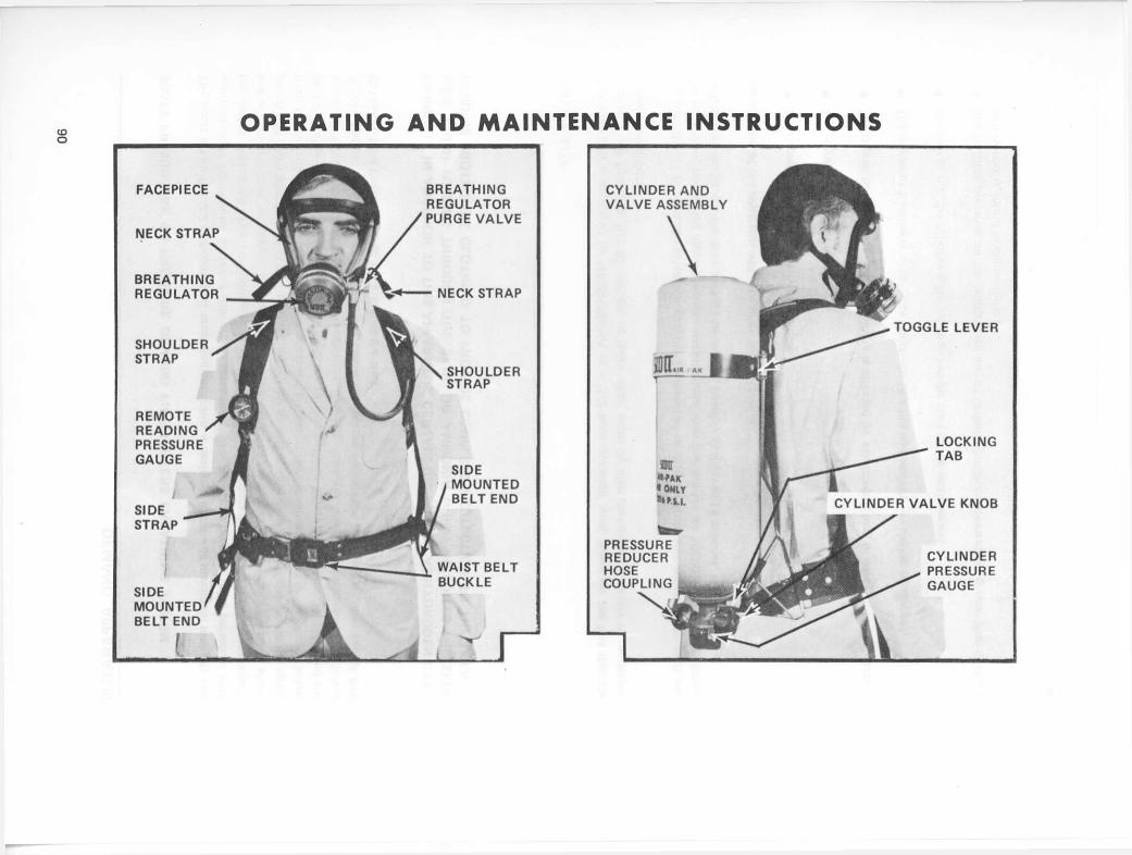
OPERATING AND MAINTENANCE INSTRUCTIONS
FACEPIECE
NECK STRAP
BREATHING REGULATOR
SHOULDER STRAP
REMOTE READING PRESSURE GAUGE
SIDE STRAP
SIDE MOUNTED BELT END
BREATHING REGULATOR PURGE V A L V E
NECK STRAP
SHOULDER STRAP
SIDE MOUNTED BELT END
WAIST BELT BUCKLE
CYLINDER AND V A L V E ASSEMBLY
\
HIT., AK |
PRESSURE REDUCER HOSE COUPLING
' ONLY
TOGGLE LEVER
LOCKING TAB
CYLINDER V A L V E KNOB
CYLINDER PRESSURE GAUGE
• The atmospheric pressure; if used in a pressurized tunnel or caisson at 2 atmospheres (15-psi gauge) the duration will be one-half as long as when used at 1 atmosphere; and at 3 atmospheres will be one-third as long.
• The condition of the apparatus.
PREPARATION FOR USE
The following procedure should be followed prior to donning the apparatus:
1. Check the cylinder pressure gauge for 'FULL ' indication. If indicated cylinder pressure is below ' F U L L / recharge cylinder to 2 216 psi or replace with a fully charged cylinder.
WARNING: CYLINDERS WHICH SHOW EVIDENCE OF EXPOSURE TO HIGH HEAT OR FLAME, SUCH AS PAINT TURNED BROWN OR BLACK, DECALS CHARRED OR MISSING, GAUGE LENS MELTED, OR ELESTOMERIC BUMPER DISTORTED, SHALL BE REMOVED FROM SERVICE AND RETESTED PRIOR TO RECHARGING.
2. Check that the breathing regulator purge valve is closed (full clockwise and pointer on knob upward).
CAUTION: DO NOT USE TOOLS TO OPEN OR CLOSE THE PURGE V A L V E . CLOSE OR OPEN FINGER TIGHT ONLY. ROTATION OF THE PURGE V A L V E KNOB LIMITED TO O N E - H A L F TURN.
3. Take a deep breath and hold it while donning the facepiece.
4. Open the cylinder valve knob counterclockwise one and one-half turns. Listen for Vibralert alarm to sound and then stop.
5. Breathe normally from the facepiece to ensure proper operation.
6. Push in and rotate the cylinder valve knob clockwise to close the valve. Inhale on the facepiece and breathe down the residual air pressure. The Vibralert alarm will sound as the pressure drops below 500 psi.
WARNING: IF THE VIBRALERT ALARM DOES NOT SOUND, REMOVE THE EQUIPMENT FROM SERVICE AND TAG FOR REPAIR.
NORMAL OPERATION
1. Open the carrying case lid.
2. Check the cylinder gauge for 'FULL ' indication. Stand to the right (top of cylinder end) of the opened case, lean forward, position, and spread out the shoulder straps. Grasp the back frame with both hands, the left on the pressure reducer, and the right on the wire frame.
91

3. Swing the apparatus straight up and over the head, keeping your elbows close to your body. Rest the apparatus on your back while still slightly bent over. The shoulder straps will slide along your arms and fall into place on the shoulders. Straighten up as you pull down on the side straps to adjust the harness to body fit.
4. Connect the waist belt buckle and adjust by pulling forward on the two side-mounted belt ends.
5. Readjust shoulder straps to assure that the weight is carried on the hips.
6. Don the facepiece as follows: (a) with head strap adjusted to a full outward position, hold the head harness out of the way with
one hand or back over the visor; (b) take a deep breath and hold it; (c) place the facepiece on the face with the chin properly located in the chin pocket; (d) pull the head harness over the head and tighten the neck straps by pulling on the two
appropriate tabs; (e) stroke the head harness down to the back, using one or both hands; (f) retighten neck straps if required.
WARNING: RESPIRATORS SHOULD NOT BE WORN WHEN CONDITIONS SUCH AS A GROWTH OF BEARD, SIDEBURNS, A SKULL CAP THAT PROJECTS UNDER THE FACEPIECE, OR TEMPLE PIECES ON GLASSES PREVENT A GOOD FACE SEAL.
7. Open the cylinder valve knob one-and-one-half turns and listen for the Vibralert alarm to sound and then stop.
WARNING: IF THE VIBRALERT ALARM FAILS TO SOUND OR DOES NOT SHUT OFF, DO NOT USE THE APPARATUS. REMOVE IT FROM SERVICE AND TAG FOR REPAIR.
8. Check the face seal by listening for flow through the regulator while holding breath. Breathe normally.
9. Check the remote reading pressure gauge on the shoulder strap occasionally for remaining supply, to allow sufficient time for egress from the contaminated area.
WARNING: WHEN THE VIBRALERT ALARM SOUNDS IT WARNS THE USER THAT APPROXIMATELY 20 TO 25 PER CENT OF THE AIR REMAINS. L E A V E THE C O N T A M INATED A R E A AT ONCE. IN AREAS WHERE MORE THAN ONE APPARATUS IS SOUNDING, THE USER CAN IDENTIFY HIS OWN ALARM BY CHANGING THE CADENCE OF HIS BREATHING. THE SOUND OF THE ALARM IS MODULATED BY INHALATION.
10. After use and when in a safe area, push in and rotate the cylinder valve knob clockwise to close the valve. Remove the facepiece and breathing regulator together.
EMERGENCY OPERATION
WARNING: THESE PROCEDURES ARE FOR EMERGENCY USAGE ONLY; CONSEQUENTLY, THE DURATION OF THE AIR SUPPLY AND THE AUDIBILITY OF THE VIBRALERT ALARM MAY BE
92

REDUCED. THE EMERGENCY MODE SHOULD ONLY BE USED TO ESCAPE FROM THE C O N TAMINATED AREA.
1. The system has no manual by-pass controls. Instead, the pressure reducer assembly includes a backup pressure reducer system that is automatically actuated if the primary reducer fails closed. When the back-up system is actuated, the Vibralert alarm sounds to warn the user.
2. Should the breathing regulator fail closed, open the purge valve (red knob) to provide an acceptable flow.
3. Should the system fail open (free flow), open the purge valve (red knob pointer down), close the cylinder valve by pushing in and rotating to regulate the flow to satisfy the requirements of the user.
4. Tag and remove the apparatus for repair.
CYLINDER REPLACEMENT PROCEDURE
1. Push in the rotate the cylinder valve knob clockwise to close the valve.
2. Remove the facepiece to bleed down the residual pressure.
3. Uncouple the pressure reducer hose coupling from the cylinder valve by rotating counterclockwise.
4. Release the toggle lever by pulling upward on its pull tab.
5. Grasp the cylinder below the band, push the locking tab below the valve, lift the cylinder free from the bottom hook, and remove.
6. Replace with a fully charged cylinder and valve assembly. Slide the top of the cylinder upward under the band. Engage the cylinder hanger in the hook at the bottom of the backpack frame.
7. Push the toggle lever to secure. Note: Do not force the toggle lever. Adjust the band for a snug fit by sliding the band assembly on
the angled side rails.
8. Align and tighten the hose coupling to the cylinder valve.
9. The apparatus is ready for reuse.
CAUTION: DO NOT LEAVE THE CYLINDER V A L V E OPEN WHEN THE APPARATUS IS NOT IN USE.
STAND-BY INSPECTION, CLEANING, AND STORAGE
Clean the apparatus after each use as follows: (a) inspect the equipment for worn or aging rubber parts or damaged components; (b) remove the breathing regulator from the facepiece;
93

H a r n e s s
C y l i n d e r
C l a m p
B a c k p l a l e
P r e s s u r e G a u g e
H e a d b a n d s — » U l t r a v u e — ' L e n s — * B a i l i e — * B y - P a s s — ' ' — M a i n - L i n e 1 — P r e s s u r e N — B r e a t h i n g F a c e p i e c e V a l v e V a t v e D e m a n d T u b e
R e g u l a l o r
94
(c) if in good condition, carefully wash the facepiece assembly with warm soap or detergent solution and thoroughly rinse in clean water;
(d) disinfect the facepiece by sponging it with a 70-per-cent solution of ethyl, methyl, or isopropyl alcohol, a quaternary ammonium solution, or a hypochlorite solution;
(e) rinse and allow to completely air dry; (f) connect the breathing regulator to the facepiece quarter-turn coupling and rotate it until it
latches in place; (g) damp sponge dirt accumulations from the rest of the apparatus; and (h) replace the apparatus in the carrying case, making sure all components are thoroughly dry.
PRESSURE DEMAND AIR MASK
DESCRIPTION
The Model 401 Pressure Demand Air Mask breathing apparatus is a pressure demand-type self-contained breathing apparatus that provides respiratory protection under conditions of oxygen deficiency or in concentrations of toxic gases. It is an open-circuit system that releases exhaled air to the surrounding atmosphere without reuse.
The Model 401 Pressure Demand Air Mask consists of an Ultravue facepiece assembly equipped with a spring-loaded exhalation valve and breathing tube, a pressure demand regulator that supplies air to the facepiece under positive pressure, a high-pressure hose that links the regulator to the Audi-Larm audible low-pressure warning device, a high-pressure cylinder to store the compressed air, and a harness assembly for carrying the apparatus on the wearer's body.
APPLICATION
The MSA Pressure Demand Air Mask provides respiratory protection in toxic atmospheres where it is necessary to avoid potential inward leakage that could result from negative pressure that is developed in a demand-type apparatus. This MSA pressure demand apparatus maintains a slight positive pressure inside the facepiece during inhalation and, through a spring-loaded exhalation valve, provides low exhalation resistance while maintaining the positive pressure inside the facepiece.
Recent OSHA standards specify the use of pressure demand apparatus only for fire fighting or emergency entry into unknown concentrations of toxic gases.
The unit is approved for entry into and escape from irrespirable atmospheres. It can be used in extremely toxic atmospheres where even minute levels of inward leakage into the facepiece would be dangerous.
The Model 401 Pressure Demand Air Mask has a rated service life of 30 minutes. Service life rating is based on the results of tests conducted by the National Institute for Occupational Safety and Health.
OPERATION
The demand-type unit adjusts automatically to deliver the air supply necessary to satisfy breathing requirements with air pressure inside the facepiece the same as outside (so under some circumstances there is a possibility of inward leakage of air). With the pressure demand air mask apparatus air is delivered to the
95

facepiece at a pressure of approximately 1 inch of water. This slight positive pressure is controlled by a spring on the regulator diaphragm. Flow stops during exhalation because the exhalation valve opens at approximately 1.5 inches of water, positive pressure. The pressure inside the facepiece, therefore, remains positive during both inhalation and exhalation. With this pressure demand arrangement, the danger of potential inward leakage is minimized, yet breathing resistance is low. Because of these operating differences, pressure demand regulators must never be interchanged with demand regulators; pressure demand facepieces must never be interchanged with demand facepieces.
ULTRAVUE FACEPIECE
The Ultravue facepiece is supplied with the Model 401 Pressure Demand Air Mask. This facepiece has a one-piece replaceable lens that is molded out of polycarbonate plastic, five adjustable head bands, and a speaking diaphragm to project the sound of the user's voice through the mask. The plastic lens is treated with Abcite (trademark of E. I. duPont de Nemours & Co. Inc.) scratch-resistant coating. Rubber components are made out of a compound that is soft and resistant to facial oils. An internal baffle controls lens fogging by deflecting exhaled air away from the lens. The baffle also directs the sound of the user's voice into the speaking diaphragm. Exhaled air vents to the surrounding atmosphere through an exhalation valve.
Ultravue facepiece accessories include a spectacle kit for mounting prescription lenses inside the facepiece without disturbing the facepiece seal, a nosecup assembly to reduce the possibility of lens fogging (NIOSH requires the use of this accessory when the apparatus is used at temperatures below 32 degrees Fahrenheit), and a cover lens to provide additional facepiece lens protection.
Two facepieces are available. Because facepiece fit is so important in a pressure demand apparatus to conserve the air supply, MSA offers the larger Clearvue pressure demand facepiece in addition to the standard Ultravue pressure demand facepiece to provide a broader range of effective face-to-facepiece fit with MSA pressure demand apparatus.
PRESSURE DEMAND REGULATOR
The pressure demand regulator supplied with all MSA Pressure Demand Air Masks can deliver high-volume air flow to meet breathing demands during periods of extreme exertion while maining a positive pressure in the facepiece. The regulator reduces the high pressure of the cylinder air to a breathable pressure, and automatically meters the flow of air to the facepiece during inhalation and exhalation, maintaining a slight pressure of approximately 1 inch of water above ambient atmospheric pressure. The MSA regulator design incorporates both high-pressure and low-pressure relief devices which preclude the possibility of damage to the regulator's internal components or diaphragm cover in case of a buildup of excessive pressure. The regulator is connected to the facepiece by the breathing tube.
Under normal operating conditions, air flow through the regulator is controlled by a main-line valve that is equipped with a round yellow knob. However, should the automatic regulator mechanism be damaged or fail to operate, a by-pass valve with a six-sided red knob provides a controlled, direct, constant flow of air from the cylinder. The difference in shapes of the main line and by-pass knobs permits identification by touch in a smoke-filled or dark area. A pressure gauge on the regulator indicates remaining air pressure in the cylinder. High-pressure air is delivered to the regulator by a length of high-pressure hose.
96

AUDI—LARM WARNING DEVICE
The Audi-Larm supplied on Model 401 Pressure Demand Air Mask gives an audible warning when the cylinder air pressure drops below a preset level. It alerts the user that the air supply is nearing exhaustion and warns the user to leave the toxic area. The assembly is installed between the high-pressure hose and the cylinder-valve outlet. It is joined to the cylinder valve by a hand-tightened coupling nut. The Audi-Larm is automatically made ready to operate when the user opens the cylinder valve.
When the cylinder pressure reaches approximately 540 psig the warning device's piston begins to strike the 2.5-inch-diameter nickel-plated brass bell. The ringing continues until the cylinder pressure drops below approximately 200 psig. The operating pressures are preset at the factory.
Total ringing time depends on cylinder capacity. When connected to a 45-cubic-foot capacity cylinder (as on the air mask), the bell will ring for approximately 6 minutes. When ringing, the Audi-Larm consumes less than 2 litres of air per minute (a small fraction of the total remaining air supply).
CYLINDERS
The Model 401 Pressure Demand Air Mask can be furnished with one of two types of cylinders, a lightweight composite (aluminum-fibreglass) cylinder which weighs approximately 10.5 pounds or the standard steel cylinder weighing 18 to 20 pounds. Both cylinders have an air-storage capacity of 45 cubic feet (1 274 litres) when they are charged to a pressure of 2 216 psig and are refilled with the same equipment. The composite cylinder and the steel cylinder are interchangeable on pressure demand air masks and demand air masks.
The steel cylinders are made of high-strength chromium-molybdenum steel. The air mask composite cylinder is a seamless aluminum-alloy tank wound over its entire surface with high-strength S-glass filaments impregnated with epoxy resin. All cylinders are hydrostatically tested to 5/3 of the rated pressure in accordance with the United States Department of Transportation regulations.
The composite cylinder has a cadmium-plated valve and the steel cylinder has a nickel-plated valve. All cylinders are equipped with a flush-mounted pressure gauge. A removable rubber guard protects the gauge if the cylinder is dropped. The cylinder-valve handwheel, mounted at a right angle to the valve stem for ease of operation and protection from damage, controls the flow of high-pressure air to the pressure demand regulator.
Note: To insure that the cylinder remains free of organic substances and other contaminants, it must be filled only with respirable air that conforms to the Compressed Gas Association Commodity Specification for Air, G-7.1, NASI Z86.1-1973, for Grade D or better gaseous air.
HARNESS AND BACKPLATE
The Cushionaire harness of the Model 401 Pressure Demand Air Mask has a foam-padded 2-inch-wide nylon strap at each shoulder, and a padded strap across the bottom of the backplate where contact is made with the wearer's back. The backplate is made of 1/8-inch-thick anodized aluminum and is painted black.
97

The cylinder clamp installed on the Model 401 Pressure Demand Air Mask is an adjustable mechanism that compensates for small variations in outside cylinder dimensions. It consists of a cam-type latch that can engage any of six slots in the stainless steel spring clip. The cylinder is changed by opening the cam latch, slipping out the empty cylinder, slipping in the recharged cylinder, and twisting the cam latch to locking position.
CARRYING CASE
Pressure demand self-contained breathing apparatus is supplied in molded plastic cases to facilitate carrying the apparatus and to protect it in storage. The pressure demand air mask case is approximately 27 by 18 by 11 inches and weighs approximately 12 pounds (empty).
SERVICE LIFE
Approvals from NIOSH/MSHA for duration of use (30 minutes) for the Model 401 Pressure Demand Air Mask are based on tests conducted by NIOSH. The apparatus was tested with a breathing machine at a use rate of 40 litres per minute and was found able to supply air for the rated service life or longer.
However, work performed by an actual user may be more or less strenuous than the work level simulated in the test procedure, and this difference will affect service life. During extreme exertion, for example, service life may be reduced as much as 50 per cent.
Service duration of each unit depends on such factors as:
• The degree of physical activity by the user.
• The physical condition of the user.
• Emotional conditions such as fear or excitement (which may increase the user's breathing rate).
• The degree of training or experience the user has had with such equipment.
• Whether or not the cylinder is fully charged at the beginning of use.
• Possible presence of carbon dioxide (CO2) in the compressed air supply at levels greater than the 0.4 per cent found in normal air.
• Atmospheric pressure, if used in a pressurized tunnel or caisson, at 2 atmospheres (15 psig) the duration will be one-half as long, at 3 atmospheres (30 psig), the duration will be one-third as long.
• Condition of the apparatus.
APPROVALS AND STANDARDS
The Model 401 Pressure Demand Air Mask is approved by the National Institute for Occupational Safety and Health (NIOSH) and Mine Safety and Health Administration (MSHA), under subpart H, 30CFR, part 11. The Model 401 has Approval TC-13F-30 for 30-minute service.
98

The Model 401 Pressure Demand Air Mask meets the requirements of the United States National Fire Protection Association (NFPA) Standard 19B-1971 (Respiratory Protective Equipment for Firefighters); it also meets guidelines for self-contained breathing apparatus contained in the American National Standards Institute (ANSI) Standard Z88.2-1969 (Practices for Respiratory Protection) and ANSI Z88.5-1973 (Practices for Respiratory Protection for the Fire Service).
MSA steel cylinders meet the requirements of the United States Department of Transportation Specification 3AA. The MSA Composite Cylinder has received the United States Department of Transportation Exemption 7277 for shipment in interstate commerce.
INSPECTION AND MAINTENANCE
The pressure demand air mask should be inspected and maintained in accordance with OSHA regulations 1910.134(f) and ANSI Z88.2 and Z88.5 standards (for the fire service) which recommend that self-contained breathing apparatus be inspected routinely before and after each use. Apparatus not used routinely but kept ready for emergency use should be inspected after each use and at least monthly.
CAUTION
Repairs of breathing apparatus must never be attempted beyond the scope of the manufacturer's recommendations.
Regulators must be sent to the manufacturer or an authorized MSA air mask service centre for adjustment or repair.
Parts must not be interchanged among self-contained breathing devices from different manufacturers.
Cylinders must be filled to required pressure before use, 2 216 psig.
Only respirable air, free of all organic substances and other contaminants, should be used to refill the cylinder. Refill air should be at least Grade D, gaseous air, as described in the United States Compressed Gas Association Commodity Specification for Air, G-7.1, ANSI Z86.1-1973.
Proper cleaning agents, such as MSA Cleaner-Sanitizer, must be used to sanitize the unit after each use so that rubber components do not deteriorate. NEVER use alcohol as a germicide because it may deteriorate the rubber. Do not apply heat to the rubber parts to speed drying.
MSA pressure demand regulators must not be interchanged with MSA demand regulators; MSA pressure demand facepieces must not be interchanged with MSA demand facepieces.
WEIGHT SPECIFICATIONS
MODEL 401 PRESSURE DEMAND AIR MASK
1. Complete apparatus with composite cylinder, approximately 25 pounds.
2. Complete apparatus with composite cylinder, in case packed for shipment, approximately 37 pounds.
99

3. Complete apparatus with steel cylinder, approximately 33 pounds.
4. Complete apparatus with steel cylinder, in case packed for shipment, approximately 45 pounds.
5 Composite cylinder only, with valve, fully charged, approximately 15 pounds.
6. Steel cylinder only, with valve, fully charged, approximately 23 pounds.
ORDERING INFORMATION
Catalog Numbers — Pressure Demand Air Mask
463831 MSA Pressure Demand Air Mask, Model 401, with composite cylinder, with Ultravue face-piece, complete in carrying case.
463814 MSA Pressure Demand Air Mask, Model 401, with composite cylinder, with Ultravue face-piece, less case.
461704 MSA Pressure Demand Air Mask, Model 401, with steel cylinder, with Ultravue facepiece, complete in carrying case.
461696 MSA Pressure Demand Air Mask, Model 401, with steel cylinder, with Ultravue facepiece, less case.
460320 Composite cylinder, 45-cubic-foot capacity, complete with valve, for Model 401 air mask.
94007 MSA steel air cylinder, 45-cubic-foot capacity, complete with valve, for Model 401 air mask.
Note: This section contains only a general description of MSA Model 401 Pressure Demand Air Mask and accessories. While uses and performance capabilities are described, under no circumstances should these products be used except by qualified, trained personnel and not until the instructions, labels or other literature accompanying them have been carefully read and understood and the precautions set forth therein followed. Only they contain the complete and detailed information concerning these products.
100

COLD WEATHER PROBLEMS
Inasmuch as the majority of open-pit mines are in areas having cold winter weather, they have the usual safety problems such as driving on icy roads, walking on slippery paths, and ice falling from roofs. Most of these dangerous conditions can, with a little effort, be made safe either by using the right equipment to stop slipping or removing the hazard. There are other hazards that may prevail such as avalanches, travel on lake ice, and chill effect developed by a combination of wind and low temperatures. These three situations may not exist at every property but at least one will.
Of course, avalanches are more frequent and larger in areas of heavy snowfall, but may occur anywhere provided:
• There is snow on an adequate slope (30 to 45 degrees) reasonably free of obstructions, such as trees, etc.
• The snow has not compacted and its shear strength is minimal.
• The snow crystals have, through pressure and/or temperatures approaching freezing, altered to globules of ice, thus developing in effect, a bed of ice marbles on a slope.
• There is some agent such as wind, an animal, or man to trigger the slide action.
Where avalanches may occur the safest course of action would be to avoid that area, but this is not always possible to do. If it must be passed, then endeavour to pass by around the bottom of the path or over the top at the head of the slide. If the avalanche path must be crossed, then endeavour to do so in the early morning before the sun melts the night frost and before wind action starts.
If a slide does occur when its path is being crossed, do not expect to outrun it as it has been estimated slides can travel in excess of 100 miles per hour. The Granduc slide in which 26 men lost their lives was estimated to contain 50,000 tons of snow, travelling at 100 miles per hour.
AVALANCHE RESCUE
In avalanche rescue work there is always the possibility that the rescue party may be exposed to avalanches themselves. For this reason no man should ever travel alone, however, the party should travel so that only one man at a time is exposed to avalanche danger.
The rescue party should stay off the avalanche paths themselves and especially stay out of the fractured zones. The safest route around an avalanche path is over the top by way of the ridges. The next safest route is along the valley floor under the avalanche.
The highest danger exists during or immediately after heavy snowfall or prolonged periods of high wind. If the temperature is low the danger may persist for many days.
It should never be assumed that a slope is safe just because it did not slide when the first man crossed it. Especially in the case of hard slabs and low temperatures avalanche release may be triggered unexpectedly,
101
even after considerable traffic on the slope. There is one case on record where an avalance trapped the 33rd man of a military patrol crossing a dangerous slope.
Lee areas, slopes beneath cornices, and deep drifts, especially those with a convex profile, are especially dangerous.
It should not be assumed that avalanches are confined to open slopes. Dense timbers usually provide good protection, but open or scattered timber stands may not necessarily hold the snow. This is particularly true in the Rocky Mountain regions where depth hoar formation is common in early winter.
Crossing an avalanche slope always involves a certain calculated risk. While it may not be possible to make even a close guess as to whether the slope will slide or not, usually the rescue party can estimate what will happen to them if it does slide while they are in the middle of it. There may be some justification for a calculated risk if the slope is short and not likely to bury the party deeply at the bottom. If the slope is long, funnels into a gully instead of fanning out, falls over cliffs, or would carry a man into rocks or trees at the bottom the risk of crossing may be more foolhardy than calculated.
Most of the dangerous avalanches originate on slopes between 30 and 45 degrees. If an avalanche slope must be crossed, clothing should be closed up, hat and mitts should be worn, and the parka hood should be raised. The chances of survival, if buried in the snow, are much better if the snow does not get inside clothing to cause chill.
An avalanche cord should be worn, tied to each man's belt and trailing out behind, or use the electronic beeper.
Advantage should be taken of natural protection offered by the terrain. Rock outcrops, clumps of trees, or ridges may offer islands of safety in the avalanche path. The route should be laid out between these. When crossing between these islands of safety only one man should advance at a time.
If a man is caught by an avalanche he should attempt by a swimming motion to stay on the surface. An attempt should be made to work to one side of the moving snow.
If it is impossible to stay on the top of the snow the man should cover his face with his hands, which will help keep snow out of the nose and mouth and allow a chance to clear a breathing space if buried. Avalanche snow often becomes very hard as soon as it stops moving.
If buried, the man should try to avoid panic. Many avalanche victims have been recovered dead, apparently uninjured, after only a few minutes of burial. The only explanation doctors can offer is that they were frightened to death.
TEN STEPS TO RESCUE BY THE SURVIVOR
1. DO NOT PANIC. The lives of your buried comrades may depend on what you do in the next hour. Check for further slide danger, pick a safe escape route in case of a repeat.
2. MARK LAST SEEN POINT. Mark the point on the avalanche path where the victim was last seen as he was carried down by the snow. This will narrow the area of your search and that of the rescue party. Use a firmly planted pole or large branch which will not be lost under a subsequent snowfall.
102
3. QUICK SEARCH. If there are only two or three survivors, they must make a quick but careful search of the avalanche before going for help. If at all possible, one man should be left at the accident scene to continue the search and guide the rescue party.
4. SEARCH SURFACE BELOW LAST SEEN POINT. Search the surface of the avalanche for evidence of the victim or clues to his location. Mark the location of any pieces of his equipment you may find, these may provide additional indicators of the path taken by the flowing snow. Search carefully and kick up the snow to uncover anything which may lie just beneath the surface.
5. SOLE SURVIVOR. If you are the sole survivor, you must still make a thorough search of the avalanche before going for help. This may seem obvious, but it is a rule all too often neglected. Even the simplest search may enable you to find the victim and free him alive.
6. THOROUGH SEARCH. If a rescue party can be summoned only after several hours or longer, the survivors must concentrate on making as thorough a search as possible with their own resources. The chances of a buried victim being recovered alive diminish rapidly after 2 hours.
7. PROBING. If the initial search fails, begin probing with a pole, loading stick, or collapsible probe below the last seen point. Trees, ledges, benches, or other terrain features which have caught the snow are the most likely places to search. If there are several survivors probing of likely spots can continue until a rescue party arrives. If you are alone you will have to decide when to break off the search and seek help, depending on how far away it is.
8. SEND FOR HELP. If there are several survivors send only two. The remaining survivors must search for the victim in the meantime.
9. GOING FOR HELP. When going for help travel carefully, avoiding avalanche dangers and injuries from trying to ski too fast. The victim's chance of survival depends on your getting through. Mark your route, especially if fresh snow is falling, so you can find your way back. Try to avoid complete exhaustion. The rescue party normally will expect you to guide them back to the accident scene unless its location is absolutely clear.
10. FIRST AID. If the victim is found treat immediately for suffocation and shock. Free nose and mouth of snow and administer mouth-to-mouth artificial respiration if necessary. Clean snow from inside clothing and place victim in sleeping bag with head downhill. Any further injuries should then be treated according to standard first-aid practices.
THE CONDUCT OF ORGANIZED RESCUE. ACTION
If a human being is buried in an avalanche prompt and organized rescue operations are the only hope of getting the victim out alive. There are records of persons who lived as long as 72 hours while buried. Ordinarily, they are either killed instantly by crushing or die within a short period from exposure, shock, and suffocation.
Suffocation is the most important cause. Investigations of a number of avalanche accidents, fatal and not fatal, lead to the conclusion that 2 hours is the average survival limit. Snow is porous and ordinarily contains enough air to support life, though not consciousness. It appears that in about 2 hours an icemask,
103

from condensation of the victim's breath, forms an air-proof seal around his face and he then, of course, dies. Rescue operations are, therefore, designed to get the victim out within the two-hour limit. Due to the special circumstances which prolong the life of the victim — he may be in an air pocket — rescue operations must not be abandoned for 24 hours at least.
Successful avalanche rescue operations depend upon trained leadership, manpower, and special equipment.
The team leader is in charge of rescue operations, he sounds a general warning and requisitions any needed equipment or volunteers. Experienced skiers who can be available on short notice are an asset to an avalanche rescue. Snowshoes may be required.
Eyewitnesses, if available, should be questioned concerning the exact location of the accident. Even if in poor physical condition any eyewitnesses should return to the accident location with the rescue team to point out where the victim was last seen. This is extremely important.
The rescue team should consist of at least three persons and preferably five. It should proceed to the avalanche area as soon as possible. Speed is important.
At the location of the accident an avalanche guard should be posted in case there are further snowslides.
If possible, the spot where the victim was last seen should be located on the surface and marked with a pole or a branch. From this point downhill the rescue team should make a hasty search of the slide surface for the victim or any part of his equipment.
If any indication of the victim is found the vicinity should be probed. If no indication is found probing should begin in likely locations. These are obstructions in the slide path such as trees, boulders, or transitions, also the top and edges of the slide. A human body is bulky and, all other things being equal, is apt to be thrown toward the surface or the sides.
If the victim is found first aid should be commenced immediately. Unless there is danger of further avalanches, the rescue team should not attempt to have the victim out of the area before treating for shock and suffocation. If the rescue team is unsuccessful in the first quick examination of the avalanche, additional men should be employed to make a thorough search. Probers are spaced shoulder to shoulder and probe every square foot. If a last seen point for the victim is known, a special group probes any section of the strip from this point downhill left by the rescue team.
Shovel crews should accompany the probers, relieving them at intervals and digging in any likely spots.
Systematic probing of any ordinary slide should not take over 3 or 4 hours. If this is unsuccessful, the slide must be trenched.
Trenches are dug parallel to the contour down to ground level or undisturbed snow at intervals of 6 feet. If sectional probes are available the interval can be increased to 10 feet. Digging begins at the tip of the slide and proceeds uphill. It is best to space the shovel crews along one trench with frequent reliefs, in this way snow from one trench can be thrown into the one just completed.
If trenching is necessary the operation ceases to be of emergency type. A constant system of relief crews must be organized.
104

1 0 0 % NO CRACKS
WITHIN 100 FEET
JS8%
STRADDLING CRACK
C I 144% DRIVING ON
ONE SIDE OF CRACK
a a
WHAT TO DO IF THE ICE CRACKS UNDER YOU - SLOW DOWN - BE READY TO JUMP.
(a) Several cracks — vehicle standing still: move it, slowly, in low gear.
(b) Several cracks — vehicle in motion: slow down to 2 mph. If cracking continues, head for thicker ice at 2 mph.
(c) One long crack — straddle cracks as in sketch B and keep moving at 2 mph, following the crack toward the shore.
ALWAYS WEAR AN APPROVED LIFE JACKET WHILE WORKING OR DRIVING ON ICE.
DEPTH OF WATER, FEET 1 2 4 8 16 32 64
MAXIMUM SAFE SPEED, MPH 2 3 5 7 10 14 20
105

Regardless of his physical injuries, the victim must be treated first for suffocation and shock. Get the snow out of nose and mouth. Apply mouth-to-mouth artificial respiration if breathing has stopped. Get the victim warm, with body heat if nothing else is available.
Leaders are responsible for the safety of their teams. Avalanche guards must be kept on duty if there is the slightest danger of another slide in the same vicinity. Rescuers must know where to go in case of an alarm. If the danger becomes critical, the team leader must not hesitate to call off operations.
In an avalanche area the following equipment should be available for rescue team:
• Twelve probes — the best probes and easiest to use are of the sectional types. Wooden or plastic loading sticks make good probes. These should be 12 feet long. Aluminum conduit also makes good probes.
• Twelve snow shovels.
• Twelve cap lamps.
• One hundred feet of climbing rope.
• First-aid kit.
• Toboggan with blankets.
A dog may be extremely useful in locating an avalanche victim. A well-trained dog is most effective but even an untrained dog will sometimes instinctively join in a search, and for this reason a dog should always be taken with a rescue team if there is one available.
ROCK AND MUD SLIDES
As the members of the rescue team are familiar with the causes of rock and mud slides these will not be discussed on the course.
A man caught in a rock or mud slide has much less chance of survival than a man caught in an avalanche, but there have been some remarkable examples of victims surviving being buried by rock or mud.
In rescue work time is vital. The victim must be recovered immediately if he is not to suffocate.
The search of the slide area should start at the toe and proceed to the edges and the surface. When digging for a victim great caution must be used in the utilization of power equipment.
As in an avalanche search a dog may be extremely useful.
ICE T R A V E L
At many mining operations part of the exploration program is held in abeyance until winter when freezing conditions have developed sufficient ice to set up diamond drills in order to drill areas covered by lakes.
106

STRENGTH OF ICE This table is for clear, blue ice on lakes. Reduce strength values 15 per cent for clear, blue river ice. Slush ice only has one half the strength of blue ice. This table does not apply for parked loads.
Thickness Permissible Load inches (clear, blue lake ice)
2 One person on foot 3 Group, in single file
(4 feet between) 7% Passenger car
(2 ton gross) 8 Light truck
(21/2 ton gross) 10 Medium truck
(31/2 ton gross) 12 Heavy truck
(7 to 8 ton gross) 15 10 tons 20 25 tons 23 45 tons 30 70 tons 36 110 tons
TRACTOR WEIGHTS
C/W Hyster and Blade
D4 - 10 tons D5 - 13 tons D 6 - 16 tons D7 - 231/2 tons D8 - 33 tons D9 - 45 tons
70 TONS
7-8 TONS
(9)
no TONS
CONTINUOUS TRAVEL WILL FATIGUE ICE AND CAUSE FAILURE. CHANGE ROADS ON ICE LANDING FREQUENTLY.
107

Elsewhere, exploration programs are held up until the ice is thick enough to take a tractor or other vehicle across lakes to areas inaccessible during the rest of the year.
Before vehicles or any equipment are driven onto the ice, a certain amount of reservations exists as to whether the ice is strong enough. Frequent testing determines the thickness and the attached table will advise if the ice is strong enough to bear the load being taken. The thicknesses are for clear blue ice only. It is said that slush ice has only half the strength of blue ice but this amount will vary according to the extent to which the snow forming the slush has been compacted.
As already stated, the table indicates the thickness of clear blue ice to support the load. Any cracks in the ice which may have been caused by expansion or loading will reduce the supporting ability of the ice in the vicinity of the cracks. The attached page of vehicle diagrams indicates the ice strength according to the relative directions of the cracks and the rate.
The small block diagram at the foot of the vehicle diagrams indicates the safe travel speed on the ice according to the depth of water under it.
When a load is placed on ice the ice bends downward toward the load. If the load is capable of motion such as a tractor or truck then dip becomes a wave travelling ahead of the vehicle as it moves. The faster the vehicle moves the angle of dip steepens and will, if the speed becomes excessive, cause a crack and permit the vehicle to break through the ice.
WIND CHILL
Wind chill is a winter phenomenon seldom appreciated when men are working on the surface in strong winds and freezing temperatures. As a result, the workmen's efficiency drops and frostbite is frequent and often accompanied by infection. Most operations have one or more thermometers to indicate temperature but very few have an anemometer or wind gauge. This instrument should be standard equipment in order that the supervisor is fully aware of freezing hazards where crews must work exposed to low temperature and wind. With this knowledge the workmen should be rotated frequently to jobs of lesser exposure and provision made for them to be able to get warmed from time to time while on the job. If frostbite does occur then standard first-aid treatment should be given.
The wind chill table should be posted wherever the wind and temperature recorder is mounted.
108

Wind speeds greater than 40 miles per hour have little additional chilling effect — United States Army Wind Chill Index.

HYPOTHERMIA
COLD KILLS IN TWO DISTINCT STEPS
Step One: Exposure and Exhaustion
The moment your body begins to lose heat faster than it produces it you are undergoing exposure. Two things happen:
1. You voluntarily exercise to stay warm.
2. Your body makes involuntary adjustments to preserve normal temperatures in the vital organs.
Either response drains your energy reserves. The only way to stop the drain is to reduce the degree of exposure.
THE TIME TO PREVENT HYPOTHERMIA IS DURING THE PERIOD OF EXPOSURE AND GRADUAL EXHAUSTION.
Step Two: Hypothermia
If exposure continues until your energy reserves are exhausted:
1. Cold reaches the brain depriving you of judgment and reasoning power. You will not realize this is happening.
2. You will lose control of your hands.
This is hypothermia. Your internal temperature is sliding downward. Without treatment this slide leads to stupor, collapse, and death.
YOUR FIRST LINE OF DEFENSE: AVOID EXPOSURE
1. STAY DRY. When clothes get wet, they lose about 90 per cent of their insulating value. Wool loses less; cotton, down, and synthetics lose more.
2. BEWARE THE WIND. A slight breeze carries heat away from bare skin much faster than still air. Wind drives cold air under and through clothing. Wind refrigerates wet clothes by evaporating moisture from the surface. Wind multiplies the problems of staying dry.
3. UNDERSTAND COLD. Most hypothermia cases develop in air temperatures between 30 and 50 degrees Fahrenheit or —1 and 10 degrees Celsius. Most outdoorsmen simply cannot believe such temperatures can be dangerous. They fatally underestimate the danger of being wet at such temperatures. Fifty-degree water is unbearably cold. The cold that kills is cold water running down neck and legs, cold water held against the body by sopping clothes, and cold water flushing body heat from the surface of the clothes. DO NOT ASK 'HOW COLD IS THE AIR' BUT ASK 'HOW COLD IS THE WATER AGAINST MY BODY.'
111

4. USE YOUR CLOTHES. Put on rain gear before you get wet. Put on wool clothes before you start shivering.
YOUR SECOND LINE OF DEFENSE: TERMINATE EXPOSURE
If you cannot stay dry and warm under existing weather conditions using the clothes you have with you, terminate exposure.
1. Be brave enough to give up reaching the peak or getting the fish or whatever you had in mind.
2. Get out of the wind and rain. Build a fire. Concentrate on making your camp or bivouac as secure and comfortable as possible.
NEVER IGNORE SHIVERING
Persistent or violent shivering is clear warning that you are on the verge of hypothermia. Make camp.
FORESTALL EXHAUSTION
Make camp while you still have a reserve of energy. Allow for the fact that exposure greatly reduces your normal endurance.
You may think you are doing fine when the fact that you are exercising is the only thing preventing your going into hypothermia. If exhaustion forces you to stop, however briefly:
• Your rate of body heat production instantly drops by 50 per cent or more.
• Violent, incapacitating shivering may begin immediately.
• You may slip into hypothermia in a matter of minutes.
APPOINT A FOUL-WEATHER LEADER
Make the best protected member of your party responsible for calling a halt before the least protected member becomes exhausted or goes into violent shivering.
YOUR THIRD LINE OF DEFENSE: DETECT HYPOTHERMIA
If your party is exposed to wind, cold, and wet, THINK HYPOTHERMIA. Watch yourself and others for symptoms.
• Uncontrollable fits of shivering.
• Vague, slow, slurred speech.
• Memory lapses, incoherence.
112

• Immobile, fumbling hands.
• Frequent stumbling, lurching gait.
• Drowsiness (to sleep is to die).
• Apparent exhaustion, inability to get up after a rest.
YOUR FOURTH AND LAST LINE OF DEFENSE: TREATMENT
The victim may deny he is in trouble. Believe the symptoms, not the patient. Even mild symptoms demand immediate, drastic treatment.
1. Get the victim out of the wind and rain.
2. Strip off all wet clothes.
3. If the patient is only mildly impaired, (a) give him warm drinks (b) get him into dry clothes and a warm sleeping bag. Well-wrapped warm (not hot) rocks or can
teens will hasten recovery.
4. If the patient is semi-conscious or worse, (a) try to keep him awake; give him warm drinks (b) leave him stripped, put him in sleeping bag with another person (also stripped). If you have a
double bag, put the victim between two warmth donors. Skin-to-skin contact is the most effective treatment.
5. Build a fire to warm the camp.
THINK HYPOTHERMIA
If you are outdoors for recreation, you presumably do not intend to jeopardize your life.
Hypothermia may be a new word to you, but it is the only word that describes the rapid, progressive mental and physical collapse accompanying the chilling of the inner core of the human body.
Hypothermia is caused by exposure to cold, aggravated by wetness, wind, and exhaustion. It is the number-one killer of outdoor recreationists.
TAKE HEED OF 'HYPOTHERMIA WEATHER.'
WATCH C A R E F U L L Y FOR WARNING SYMPTOMS.
CHOOSE EQUIPMENT WITH HYPOTHERMIA IN MIND.
THINK HYPOTHERMIA!
113
HOW LONG CAN YOU SURVIVE?
An important side benefit of cold-water research was the development of an uncomplicated method of restoring body heat to people who have suffered a severe loss.
It was found that it was better to keep clothing on, even shoes, hat, and gloves in cold water because it acts as insulation. This assumes that flotation is not a problem.
In rewarming a person's body, the traditional method is to immerse the subject in hot water, but this has its dangers.
Inner body temperature continues to drop even after a person has been removed from the cold. A hot bath warms the surface of the body and sends cold blood coursing through the vital organs. To a heart already threatened by cold this could be the fatal strain.
Hayward and his fellow scientists developed a new technique. They found that a portable apparatus much like a bedroom vapourizer can be used to administer heated, moistened air to the rescued person. In this way heat is delivered to the places where he needs it most, the heart, lungs, and brain.
When this method was used, subjects' temperatures began climbing after only minimal afterdrops were recorded in eardrums and rectal temperature probes.
Unconsciousness can occur when deep body temperature falls to about 90 degrees Fahrenheit (32 degrees Celsius) and heart failure is the usual cause of death when the body core cools to about 85 degrees Fahrenheit (30 degrees Celsius) or below.
Survival time is increased by extra body fat, decreased by small body size.
It is better to stay still in cold water, if flotation is not a problem, because swimming increases cooling by more than one-third.
Treading water speeds up cooling by 34 per cent but drown proofing cools the body 82 per cent faster because of heat loss through the head when it is immersed in water.
Drown proofing works well in warm water. As with treading water, it is a way of staying afloat. It involves floating with the lungs full of air and the head just below the water. About every 15 seconds the person raises the head to take a deep breath.
By floating in a fetal position with the arms tight against the sides of the chest, and with thighs raised to preserve heat in the groin, cooling is retarded and predicted survival time increases about 50 per cent.
The same effect can be achieved by two or more people huddling together with the sides of their chests held close together.
Although it was believed you could survive only about 30 minutes in water at a temperature of 10 degrees Celsius, the team found that the average-sized male could last 2.5 to 3 hours before his heart fails from a body temperature dropping from 38 to 30 degrees Celsius.
114

Most women have slightly more fat than men, but they cool about 15 per cent faster because of their smaller size, and children cool even more quickly than women. Alcohol does not retard body cooling; it increases the rate by about 20 per cent.
In water 10 degrees Celsius the average person swimming in a life jacket cools 35 per cent faster than when staying still, and would probably be overcome by hypothermia after swimming less than a mile. Conclusion: do not try to swim ashore if you are more than three-quarters of a mile from land.
115

VEHICLES AND DUMPS
In the introductory remarks made at the commencement of this course, attention was drawn to the very large number of fatalities and reported dangerous occurrences involving the use of vehicles. When the fatalities caused by vehicles capsizing are added to those where people have been struck by a vehicle, the total is 29 out of the 54 fatalities which occurred in the open pits and quarries of this province during the past 20 years. When the dangerous occurrences involving the same situation are added together, the total is 47. In other words, more than one out of every three vehicular accidents has resulted in a fatality.
When the causes of these accidents are analysed, it would appear that the majority could have been avoided by due consideration having been given to the following items:
• Adequate training of drivers.
• Improved location, construction, and maintenance of roads.
• Adequate design and maintenance of vehicles.
• Proper dumping procedures.
• Lighting.
The first two items are those administered by management, who should ensure that all drivers receive adequate instruction and that all roads are adequately constructed and maintained to minimize loss of life and equipment.
Because many accidents have resulted from inadequate brakes on vehicles, this Ministry has recommended legislation to require any vehicle operating in and around mines be equipped with an adequate braking system capable of stopping and holding the vehicle on any grade that the vehicle, when loaded, is capable of climbing.
Proper dumping procedures involve the location, development, and daily operating procedures. This last item involves such details as the use of a dumpman, brow logs, berms, bulldozer, etc. When establishing and operating any dump for either waste or ore, due consideration should be made to the following features:
• Do not locate the dump immediately above a highway, railway, watercourse, or dwelling where any subsequent movement of the dump material would endanger these locations.
• Determine if the dump base will support the fill without failure.
• Divert and keep all water diverted from the dump.
• Do not dump into any natural drainage course.
• In areas of heavy snowfall, dump at the steepest point during the snow period and when spring thaw starts, dump in the areas of least snow depth. This practice will avoid sudden settling or slumping.
• Develop and maintain, through daily checks, a safe dump and safe dumping operational procedures.
117


RESCUE FROM VEHICLES
INTRODUCTION
This paper will offer suggestions for the handling of casualties in the event of road accidents due to collision or vehicles that have left the roadway because of skids and the like. No attempt will be made to describe in detail first-aid measures that may be required in such accident situations. However, the immediate problem is one of preserving life and a thorough knowledge of first aid is essential to all those who undertake such rescue missions.
RECONNAISSANCE
It is essential to the success of the mission that the rescue team leader make a rapid summation of the rescue problem in order that it may be tackled in an efficient manner.
PRIORITIES
The following is a suggested order of priorities:
1. Team safety.
2. Check stability of vehicle.
3. Approach vehicle from a safe angle; care should be taken not to disturb vehicle if precariously balanced.
4. Anchor vehicle.
5. Further danger to the victims due to spilled fuel, fire, or leaking batteries.
6. Conditions of the victims — check for excessive bleeding and absence of breathing.
7. Ascertain if further assistance is required — cutting gear, wreckers to pull vehicles apart, ambulance, etc.
8. Methods of extracting victims and deciding order of evacuation according to seriousness of injuries and type of vehicle, for example, pick-up, 100-ton, or 200-ton truck.
9. General first aid.
REMOVAL DANGERS
1. Use wheel blocks.
2. Control traffic, set out reflector or flares.
119
3. Spilled fuel or a leaking tank may be extremely hazardous. Gasoline vapours are heavier than air and will collect in hollows or flow to lower ground but are easily blown about by the wind. An explosive mixture may be set off by: (a) steel-clad boots striking a spark from a stone; (b) cigarette butts carelessly dropped into the vapour; (c) electrical circuits in the car; and (d) hot engine parts.
4. Disconnect and remove battery, if possible. This action will eliminate the making of accidental sparks in any part of the car electrical circuitry.
FRACTURES
If there is any doubt in the mind of the senior first-aid attendant that necks or. backs may be dislocated or broken, then the victim must be treated as though the spinal column is fractured and a fracture board must be used to handle the patient. The rescue vehicle should carry a half-length fracture board and a complete one as well, also a cervical collar for a broken neck.
FRACTURE BOARD
This stretcher is made from 3/4-inch plywood and should be 6 feet by 6 inches by 20 inches with hand holes around the sides and straps attached to it for tieing the patient in position. It has been found that where a whole board cannot be used due to confined space, a half board is a necessary first step. The patient's head, chest, and hips are held firmly to the board by straps and the patient can then be manoeuvred out of the vehicle and onto the whole board for moving to hospital (both boards together). The stretchers need plenty of padding correctly distributed.
SPLINTS
When broken bones occur they must be correctly splinted before the victim is moved.
REMOVAL FROM DRIVER'S SEAT
After completing all possible first aid, then:
1. Slide the seat back as far as possible.
2. One man gets into back of car behind victim, passes his arms under victim's shoulders, crosses his forearms, and holds wrists.
3. Second man at side of car holds stretcher board ready and passes it under victim as first man lifts him clear of the seat.
4. Third man at opposite side of car helps to slide victim lengthwise onto board for removal.
120

REMOVAL FROM UNDER DASHBOARD
Four men are required.
1. First aid is applied.
2. Back board placed on front seat on edge against the back.
3. First man supports victim's head, controlling it through manoeuvre.
4. At signal from leader, victim is gently raised keeping back and hips against front seat and up and over to a position so that the victim is lying on the seat on his side. Care must be taken to ensure that the victim is kept held in contact (therefore in a straight line) with the board which is then turned so that it lies flat on the seat, then removed.
REMOVAL FROM BACK OF CAR
After a car accident, sometimes a victim is found lying between the back seat and the back of the front seat on the floor. Render first aid, then:
1. If possible, remove the back seat.
2. Two men lean over back of front seat and grasp victim by his clothes at the shoulder, chest, waist, and thigh; two more men must control the head and legs.
3. A stretcher board is placed on the floor or on the seat if this has not been removed.
4. Carefully logroll the victim onto the board if on the floor, or raise him onto the board at seat level with every precaution and remove.
GAINING ACCESS
Where vehicles are so damaged that means of access must be made by an emergency method the following alternatives are suggested:
• Removing the windscreen or back window.
• Forcing open the trunk and removing the barriers of metal and upholstery.
• Cutting through the bottom or top of the passenger space or cutting away the doors.
OXY-ACETYLENE CUTTING
This method is rapid and effective but fraught with dangers.
121
• The head of the cutting flame produces fumes from the paint, oil, grease, and upholstery in the car. The roof lining and upholstering catch fire.
• The cutting operation can only be carried out if the trapped victims are protected from the sparks and cutting flames with asbestos blankets.
Carbon dioxide extinguishers cannot be used to control any fire that may be caused as the gas will displace air in the passenger space and does not support life. Only dry chemical extinguishers should be used, and then only with care.
OTHER CUTTING DEVICES
A car body cutter (like a large can opener) can be used quickly and effectively without the dangers outlined previously but is only good for thin sheet metal.
A wheel saw is also effective and the sparks given off are not so hot as with gas cutting but may ignite gasoline fumes.
CONCLUDING REMARKS
Vehicle accidents where persons are injured have problems that are nearly always unique and so varied that no description could cover all circumstances. The few suggestions that follow lay down some principles to be followed, namely:
1. Check approach and stability of vehicle.
2. Restore breathing if not present.
3. Control bleeding.
4. Treat fractures.
5. If fire is present victims must be removed to a safe distance immediately, regardless of their injuries.
Practise with a vehicle is essential. 'Victims' should be removed from all types of vehicles used on a property.
Casualty simulation of the victim or victims will provide more realism and better training.
122

SPINE BOARDS
Spine boards are of great value in extricating all types of injured, particularly the most frequently mishandled injury, fracture of the spine with actual or impending damage to the cord.
The spine board is ideal for the victim with such an injury, but once again, preparation of this patient so that he can be removed is a step-by-step procedure.
A sitting victim with cervical injury, for example, is secured to the short spine board and then removed. The collar is applied first. This is fashioned easily from two or more universal dressings, folded lengthwise, and held in place by safety pins or soft roller dressings. The short board then is slid behind the patient on an angle and positioned. As the board is waxed it slides easily. The victim's head is then secured to the board by using the headband and chin strap. A neck roll may be necessary in some cases to allow fixation in the optimum position.
Next, the victim is secured to the board. Two 9-foot-long straps are passed through the upper hand holes, behind the board, out the lower hand holes and around the thigh from outside to inside, and finally under and over the thigh to the chest buckle, staying as high as possible in the groin. The injured and the board are now a unit.
The victim then is turned in the seat so that he faces the side of the car, and his feet and legs are outside. If his leg is fractured, the legs are tied together with triangular bandages before the victim is turned. Three ties are sufficient, a figure eight about the foot and ankle and ties below and above the knee.
Once the victim is turned, his legs will be accessible, allowing definitive splinting with blanket rolls, padded boards, or inflatable splints.
If the victim is small so that two average men can lift him, he then is lifted out of the car. Each attendant uses the upper hand hole on the board and passes his forearm under the buttocks of the victim and grasps the other attendant's hand. They place the victim, his thighs still flexed in the straps, on a litter or stretcher. The straps then are released and used to secure the victim, still on the short board, to the litter or stretcher.
The victim is taken to the hospital on the board which should be removed only by a physician.
If the victim is too large to be lifted out then he may be removed as a unit on the long board. First, he is secured to the short board, placed flat on the seat, and the long board is pushed beneath him and the short board. The victim then can be lifted out on the long board and he should remain on it, secured by straps. Straps are passed easily through the hand holes or strap holes as the board has 1-inch half rounds on its underside.
Removal of many victims, even though they may have no evidence of spine injury, is easier with the long board instead of pulling, tugging, and lifting them out. This patient may be turned and slid onto the board, or the board may be pushed under him.
One of the most difficult to remove is the victim who has been thrown on the floor between the front and rear seats. Here again the long board is valuable. Being beveled and waxed, the board can be pushed under the injured by attendants at both sides of the vehicle.
123

124

The first step toward removal of such a victim is to obtain more space by lifting out the back seat. The victim is then examined and given whatever care is necessary at this point.
The long board is positioned under the victim's shoulders and head and, guided from foot end, he is then placed onto the long board.
An ejected victim suspected of having spine injuries traditionally is lifted by blanket lift, by three, four, or six-man lift and placed on litter, face up or face down. It is common practice that after such a patient is hospitalized he is turned on his side, if necessary, for examination.
Using the long board, the same method of turning is valuable at the accident scene, and the victim will not sag. By grasping the victim's clothing, attendants can turn him partway, place the long board alongside him, and turn him back on the board. The straps are passed across the victim, fastened, and he is ready for transport.
Usually the ejected victim is out in the open but on occasion he is found under the vehicle and he can be extricated with relative ease with the long board.
Use of the long and short spine boards definitely lessens the potential damage to the victim, especially one with an injured spine, and makes difficult tasks relatively easy.
125
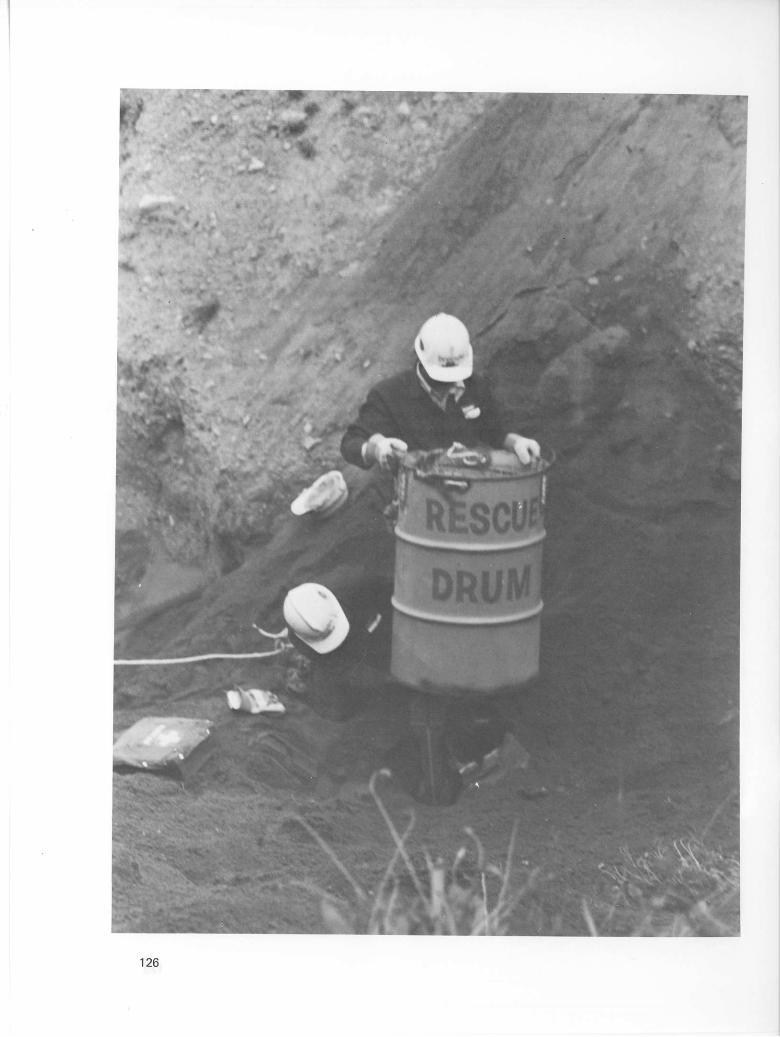
126

THE RESCUE DRUM
The rescue drum is to assist in the rescue of persons trapped by sand, gravel, or similar material in hoppers, bunkers, or stockpiles.
Around mines and gravel pits where the materials mentioned above are stored in hoppers or bunkers or stockpiled and extracted from the bottom, there is the danger of persons being trapped by falling into the draw point or the sudden collapse of material due to hangup of material.
When this happens the victim may not be completely covered by the material and will need protection from further sloughing while being rescued.
The rescue drum, which is open ended (both ends removed), can be lowered over the victim by ropes and, if necessary, a second drum may be added to give more height. Once the drum is in place you should make sure it is as secure as possible.
The sides may now be blocked or sloughed for safe working conditions.
If the victim has breathing restrictions due to pressure of material on chest and abdomen, this restriction should be removed as soon as possible as this will restrict ventilation to the patient. Oxygen should be given as soon as possible. If breathing has stopped, artificial respiration (mouth-to-mouth resuscitation) must be started at once.
The conditions may vary in every incident of this nature, but common sense and the occasional practice with the rescue drum will enable you to give assistance to any victim should the need arise.
127
128
FIBRE ROPES
Rope is used to rescue persons from trapped areas and is one of the most important pieces of equipment in such operations. Therefore a solid knowledge of its characteristics and thorough training in its care and handling are essential.
They are used in many ways to release victims from trapped areas and to move heavy objects.
Fibre ropes are made up of a number of fibres of manila, sisal, hemp, or other plant, animal, or synthetic material spun into yarns. The yarns are then twisted into strands, and three or more strands are twisted into a rope.
STRENGTH OF FIBRE ROPES
The strength is governed by the size (diameter), condition, and care in which it is used. The greater the diameter, the greater is the (stress) load. [Check safe working load (SWL).]
SIZE AND USES
There are three sizes used in rescue work: 1/2-inch, 3/4-inch, and 1-inch.
• 1/2-inch rope is used for lashing and guy lines.
• 3/4-inch rope is used for life saving from upper or lower levels and guy lines.
• 1-inch rope is used for moving heavy material and lifting devices, and also as life-saving lines in certain circumstances.
SAFE WORKING LOAD (SWL) OF FIBRE ROPES
The safe working load is established in order to ensure a wide safety margin for both rescue workers and casualties in all circumstances. Federal specifications have established the safe working load as being one-fifth the minimum breaking strength. The breaking strength is determined by taking several breaking tests on the rope.
minimum breaking strength SWL = z
D
Examples:
(a) To determine the SWL of a 1-inch manila rope with a minimum breaking strength of 9,000 pounds:
9,000 pounds = 1,800 pounds SWL
5
129

WIRE ROPE
Safe Load in Pounds for New Improved Plow Steel Hoisting Ropes 6 Strands of 19 Wires, Hemp Centre
Based on a Safety Factor of 5/1
Weight Weight per Safe per Safe
Diameter Foot Load Diameter Foot Load in. lb. lb. in. lb. lb.
1/4 0.10 1,100 1 1.60 16,000 5/16 0.16 1,800 1 1/8 2.03 21,200 3/8 0.23 2,500 1 1/4 2.50 26,000 7/16 0.31 3,300 1 3/8 3.03 31,400 1/2 0.40 4,300 1 1/2 3.60 37,000 9/16 0.51 5,400 1 5/8 4.23 43,200 5/8 0.63 6,600 1 3/4 4.90 49,600 3/4 0.90 9,400 1 7/8 5.63 56,800 7/8 1.23 12,800 2 6.40 64,400
2-IN-1 NYLON ROPES
Approximate Average
Diameter Breaking Strength in. lb. (1)
1/4 2,200 5/16 3,400 3/8 4,800 7/16 6,500 1/2 8,300 9/16 11,200 5/8 14,500 3/4 18,000
13/16 22,000 7/8 26,500
1 31,300
130

(b) To determine the SWL of a 3/4-inch manila rope with minimum breaking strength of 5,400 pounds:
5,400 pounds = 1,080 pounds SWL
5
(0 To determine the SWL of a 1/2-inch manila rope with minimum breaking strength of 2,650 pounds:
2,650 pounds = 530 pounds SWL
5
Ropes used in pulley blocks ahould have a diameter not less than one-eighth the diameter of the pulley block, for example, an 8-inch-diameter block should be supplied with a rope 1 inch in diameter.
A splice reduces the strength of a rope to 90 per cent of its normal strength.
A knot reduces the strength of a rope to 50 per cent of its normal strength.
Wire ropes are approximately nine times as strong as fibre ropes of the same diameter.
DO'S AND DON'T'S IN USE OF ROPES
Don't pull ropes over rough edges. Don't use blocks or pulleys of too small diameter. Don't pull a rope around a sharp bend. Don't drag a rope along the ground when not necessary. Don't kink a rope. Don't keep same running position of rope on block, etc. Don't allow a rope to come to a sudden stop or jerk Rope strength is weakened if it is wet, knotted, or treated with oil, tar, etc. Don't pile your rope in a heap, coil clockwise, and avoid kinks. Dry your rope out before storing away (if wet) and clean same. Hang your rope up when storing away. Coil and hang your rope on wooden racks or pegs. Keep ropes stored away from strong sunlight. Store ropes in dry, normal temperatures. Chemical wastes will destroy or weaken your ropes. New ropes should be stretched before being put into service.
131

1

RAPPELLING
Several rappelling techniques may be used, only the body rappel is given here. The climber should face the rappel point and straddle the rope. From the rappel point the rope goes between the legs, under the left buttock, up and in front of the left hip, across in front of the chest, over the right shoulder, and across the back to the left or braking hand. The right hand grasps the rope running to the rappel point at about shoulder height. It is used only to steady the body and hold it in the desired position. Trying to support the weight with the right hand will result in a rope burn. The left hand can be held to the rear wherever comfortable, so long as the arm is nearly straight. Friction can be increased if the hand is moved forward, reduced if moved backward. Control of speed will be learned more easily, however, if the hand itself is used as a brake. The climber then leans away from the rock just far enough for his feet to hold, with his weight supported by the rope, and descends slowly, leading with the left leg to make certain that the rope stays in place. He soon learns to rappel in longer and longer bounds and to use insulation against heat on the shoulder and under the buttock.
133

134

B A R - K A R A B I N A R F O R R A P P E L L I N G
135

WHIPPING ENDS OF A ROPE
136

TERMS USED IN CONNECTION WITH ROPES
STANDING PART
ROUND TURN M O U S I N G

I
KNOTS USED IN RESCUE
CLOVE HITCH

1
KNOTS USED IN RESCUE
BOWLINE

KNOTS USED IN RESCUE
DOUBLE BOWLINE USED AS v
LIFE BASKET

KNOTS USED IN RESCUE
0

Step N o . 1: M e a s u r e f o u r double a r m lengths a c r o s s the body i n o r d e r to s u p p l y enough w o r k i n g l i n e and t ie an o r d i n a r y s l i p knot to f o r m the f i r s t l oop f o r one of the v i c t i m ' s l e g s , E x a m p l e A .
S tep N o . 2: P l a c e the loop thus f o r m e d a r o u n d the v i c t i m ' s r i g h t t h i g h w e l l up into the c r o t c h . W i t h the l e f t h a n d , h o l d the eye of the s l i p knot i n the c e n t r e of the v i c t i m ' s body j u s t be low h i s c h e s t , E x a m p l e B .
142
Step N o . 3: P l a c e the s e c o n d loop a r o u n d the v i c t i m ' s l e f t t h i g h w e l l up into the c r o t c h and s t a r t f o r m i n g the t h i r d l oop t h r o u g h the eye that is h e l d s e c u r e by the l e f t h a n d , E x a m p l e C .
Step N o . 4: P l a c e the t h i r d l oop u n d e r the v i c t i m ' s le f t a r m and o v e r h i s r i g h t s h o u l d e r then b a c k t h r o u g h the eye , m a k i n g s u r e the rope e n t e r s t h r o u g h the eye f r o m the u n d e r s i d e , E x a m p l e D .

Step N o . 5: C o n t i n u e the l i n e a c r o s s the le f t s ide of the v i c t i m ' s n e c k a c r o s s the b a c k and u n d e r the r i g h t a r m and b r i n g the l i n e b a c k t h r o u g h the eye on the c h e s t , thus f o r m i n g the f o u r t h l o o p , E x a m p l e E .
S tep N o . 6: T i g h t e n the eye s n u g l y on a l l f o u r loops by p u l l i n g on the l i f t i n g l i n e and w o r k i n g the l o o p s . S e c u r e the eye to the loops w i t h two h a l f - h i t c h e s to p r e v e n t s l i p p i n g and t i g h t e n i n g of the knot on the v i c t i m ' s body , E x a m p l e F . The c o m p l e t e d knot i s s h o w n i n E x a m p l e G .
144
KNOTS USED IN RESCUE
o o © SINGLE SHEET BEND
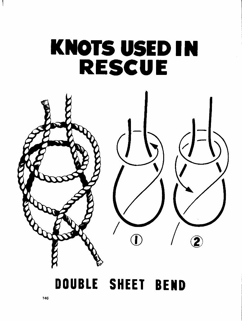
KNOTS USED IN RESCUE
DOUBLE SHEET BEND

KNOTS USED RESCUE
T I M B E R HITCH ROUND TURN AND
TWO HALF HITCHES

INSTRUCTIONS F O R TYING B O W L I N E - O N - A - B I G H T
00
Double rope to desired length, depending on the size of the two loops needed when knot is complete. Grasp rope in left hand at Point (A), Step #1 , and complete thumb knot as in Step #2.
S T E P #4 Continue to pull rope until knot i secure. As shown in Step #5.
With thumb knot complete, and grasping rope at cross over at Point (A), Step #2, find centre of bight - Point B , Step #2.
With completed knot, you should be left with two equal loops as long as you have held the rope secure with no slippage where Point (B) crosses over Point (A). Note dead end of rope at Point (D) should be at least 12" long.
C a r r y Point (B) back to Point (A) and hold under thumb of left hand as shown in Step #3. Grasp double rope at Point C and pull up through thumb knot as in Step #4.
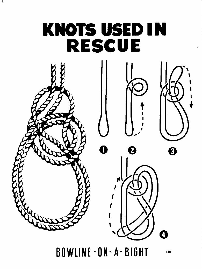
KNOTS USED IN RESCUE
BOWLINE - O N - A - B I G H T <••

1
SQUARE LASHING
O ©

ROUND LASHING

FIGURE OF 8 LASHING

DIAGONAL LASHING
DIAGONAL LASHING

!
STANDING DERRICK

A" FRAME

TRIPOD
FIGURE OF EIGHT, LASHING C
ALTERNATIVE METHOD OF SECURING BASE
SLING AS SHORT AS POSSIBLE
ROPE TACKLE
SQUARE LASHINGS
/ \
DISTANCE BETWEEN BASE OF POLES MUST NOT BE MORE THAN HALF THE HEIGHT TO CRUTCH
156
SNATCH BLOCK BLOCK LASHINGS AS NEAR 6R0UN0 AS POSSIBLE

JIBS LOWERING BY
SNATCHBLOCK
AND ONE INCH ROPE
0

BLOCKS AND TACKLE IN RESCUE
SHELLS
STANDARD T W O - S H E A V E B L O C K

PRINCIPLES tFUFTIHG^METIOiS ISED FOR RESCUE TRAINING
SINGLE
C TWO SIN6LE
c
i
WHIP LUFF DOUBLE LUFF
THEORETICAL I I ADVANTAGE I TO I 2 TO I 2 TO I 3 TO I 4 TO I
ACTUAL Q / i n ADVANTAGE 3 / I U W 3
LIFTING TACKLE L I G H T G I N
THEORETICAL K r i I ADVANTAGE 9 " I
ACTUAL * ADVANTAGE
H E A V Y G I N
6 " l
3 V.
RUNNER TACKLE LUFF T A C K L E
THEORETICAL I ACTUAL ADVANTAGE AOVANTAG
4-1 3%
TWO SINOLE
159

HOLDFASTS
COMBINATION LOG PICKET HOLDFAST

1
HOLDFASTS AND PICKETS
PICKETS USED AS HOLDFAST

TRANSPORT OF CASUALTIES BLANKETING A STRETCHER
SECURING TO A STRETCHER
AN IMPROVISED LASHING
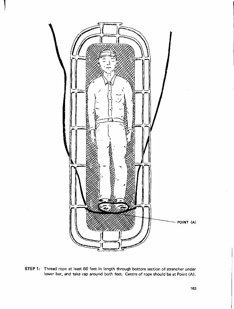
163

164

165
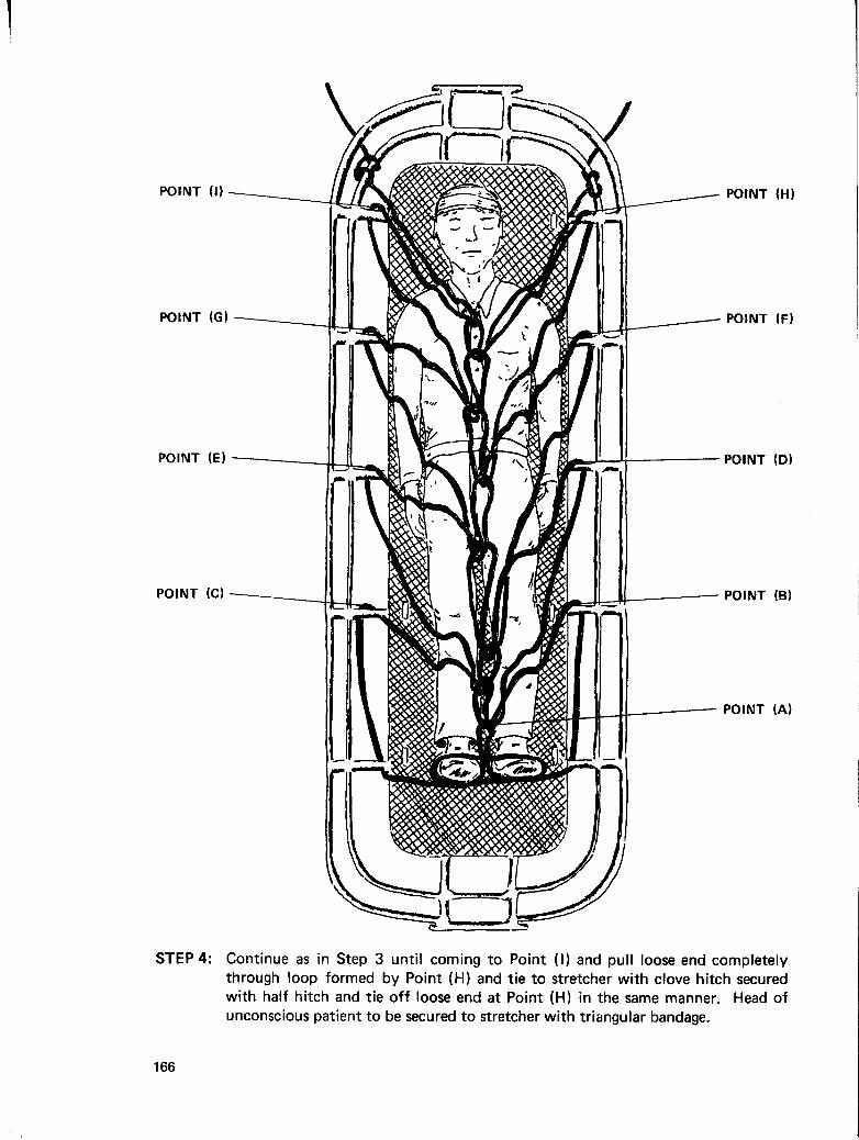
STEP 4: Continue as in Step 3 until coming to Point (I) and pull loose end completely through loop formed by Point (H) and tie to stretcher with clove hitch secured with half hitch and tie off loose end at Point (H) in the same manner. Head of unconscious patient to be secured to stretcher with triangular bandage.
166

I
TRANSPORT OF CASUALTIES
BOWLINE DRAG
METHOD SUITABLE
FOR ONE RESCUER 167
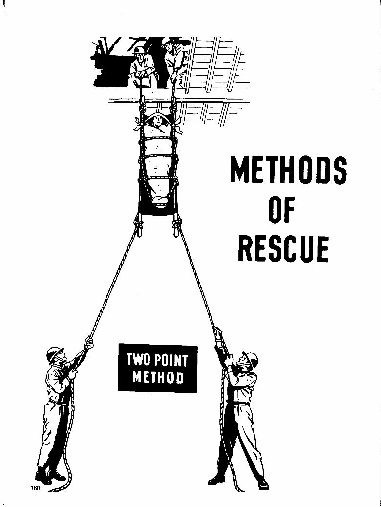
1

Ministry of Energy, Mines and Petroleum Resources