manley valve locks simply the best! · 53 super 7° valve locks steel material heat treated and...
TRANSCRIPT
52 P H O N E : 7 3 2 . 9 0 5 . 3 3 6 6 F A X : 7 3 2 . 9 0 5 . 3 0 1 0
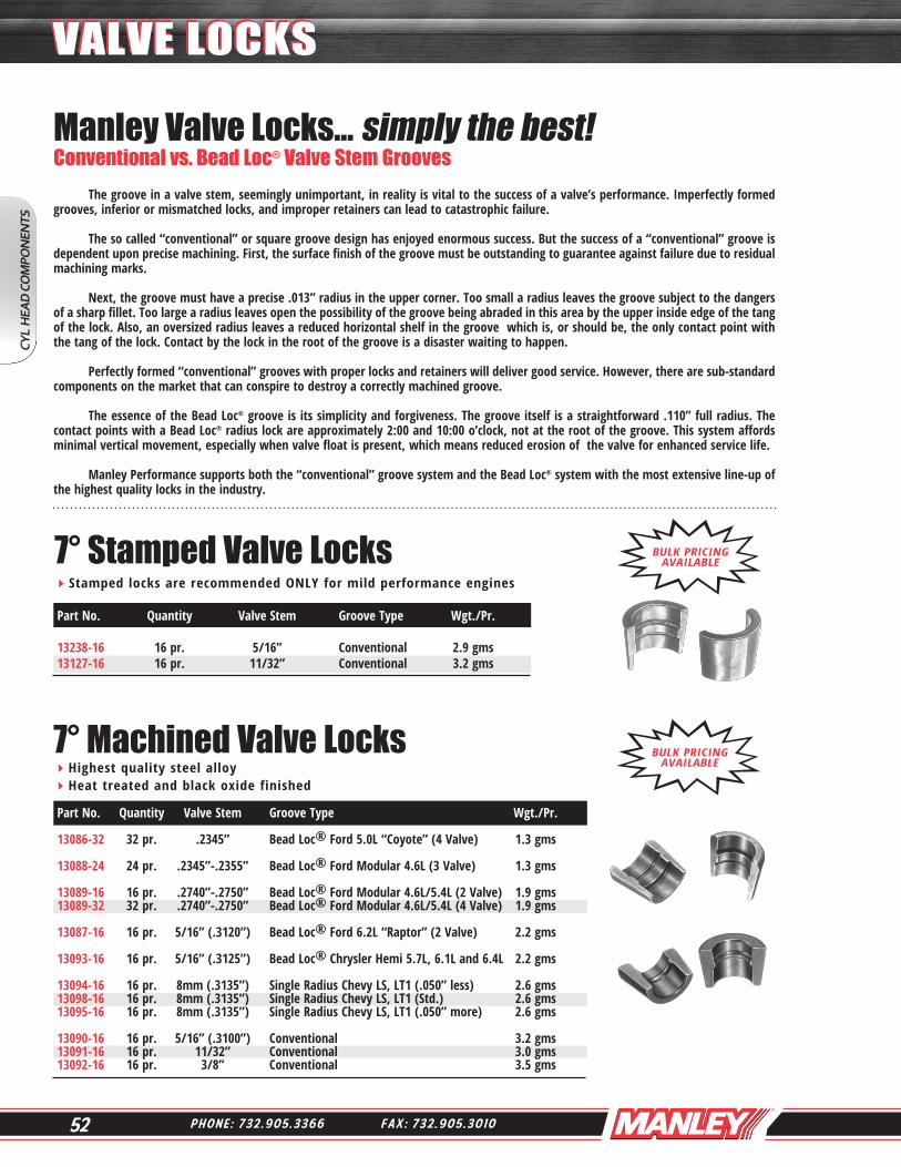
7° Stamped Valve LocksStamped locks are recommended ONLY for mild performance engines
7° Machined Valve LocksHighest quality steel alloy Heat treated and black oxide finished
The groove in a valve stem, seemingly unimportant, in reality is vital to the success of a valve’s performance. Imperfectly formed grooves, inferior or mismatched locks, and improper retainers can lead to catastrophic failure.
The so called “conventional” or square groove design has enjoyed enormous success. But the success of a “conventional” groove is dependent upon precise machining. First, the surface finish of the groove must be outstanding to guarantee against failure due to residual machining marks.
Next, the groove must have a precise .013” radius in the upper corner. Too small a radius leaves the groove subject to the dangers of a sharp fillet. Too large a radius leaves open the possibility of the groove being abraded in this area by the upper inside edge of the tang of the lock. Also, an oversized radius leaves a reduced horizontal shelf in the groove which is, or should be, the only contact point with the tang of the lock. Contact by the lock in the root of the groove is a disaster waiting to happen.
Perfectly formed “conventional” grooves with proper locks and retainers will deliver good service. However, there are sub-standard components on the market that can conspire to destroy a correctly machined groove.
The essence of the Bead Loc® groove is its simplicity and forgiveness. The groove itself is a straightforward .110” full radius. The contact points with a Bead Loc® radius lock are approximately 2:00 and 10:00 o’clock, not at the root of the groove. This system affords minimal vertical movement, especially when valve float is present, which means reduced erosion of the valve for enhanced service life.
Manley Performance supports both the “conventional” groove system and the Bead Loc® system with the most extensive line-up of the highest quality locks in the industry.
Manley Valve Locks... simply the best!Conventional vs. Bead Loc® Valve Stem Grooves
Part No. Quantity Valve Stem Groove Type Wgt./Pr. 13238-16 16 pr. 5/16” Conventional 2.9 gms 13127-16 16 pr. 11/32” Conventional 3.2 gms
BULK PRICING AVAILABLE
BULK PRICING AVAILABLE
Part No. Quantity Valve Stem Groove Type Wgt./Pr.
13086-32 32 pr. .2345” Bead Loc® Ford 5.0L “Coyote” (4 Valve) 1.3 gms
13088-24 24 pr. .2345”-.2355” Bead Loc® Ford Modular 4.6L (3 Valve) 1.3 gms 13089-16 16 pr. .2740”-.2750” Bead Loc® Ford Modular 4.6L/5.4L (2 Valve) 1.9 gms 13089-32 32 pr. .2740”-.2750” Bead Loc® Ford Modular 4.6L/5.4L (4 Valve) 1.9 gms 13087-16 16 pr. 5/16” (.3120”) Bead Loc® Ford 6.2L “Raptor” (2 Valve) 2.2 gms
13093-16 16 pr. 5/16” (.3125”) Bead Loc® Chrysler Hemi 5.7L, 6.1L and 6.4L 2.2 gms 13094-16 16 pr. 8mm (.3135”) Single Radius Chevy LS, LT1 (.050” less) 2.6 gms 13098-16 16 pr. 8mm (.3135”) Single Radius Chevy LS, LT1 (Std.) 2.6 gms 13095-16 16 pr. 8mm (.3135”) Single Radius Chevy LS, LT1 (.050” more) 2.6 gms 13090-16 16 pr. 5/16” (.3100”) Conventional 3.2 gms 13091-16 16 pr. 11/32” Conventional 3.0 gms 13092-16 16 pr. 3/8” Conventional 3.5 gms
CYL
HEA
D C
OM
PON
ENTS
VALVE LOCKSVALVE LOCKS
53W W W . M A N L E Y P E R F O R M A N C E . C O M
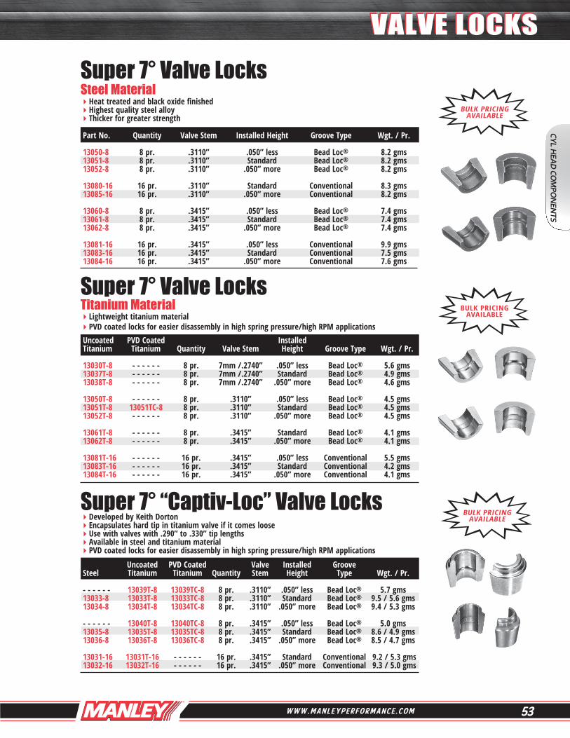
Super 7° Valve Locks Steel MaterialHeat treated and black oxide finished Highest quality steel alloy Thicker for greater strength
Super 7° Valve Locks Titanium MaterialLightweight titanium material PVD coated locks for easier disassembly in high spring pressure/high RPM applications
Super 7° “Captiv-Loc” Valve LocksDeveloped by Keith Dorton Encapsulates hard tip in titanium valve if it comes loose Use with valves with .290” to .330” tip lengths Available in steel and titanium material PVD coated locks for easier disassembly in high spring pressure/high RPM applications
Part No. Quantity Valve Stem Installed Height Groove Type Wgt. / Pr. 13050-8 8 pr. .3110” .050” less Bead Loc® 8.2 gms 13051-8 8 pr. .3110” Standard Bead Loc® 8.2 gms 13052-8 8 pr. .3110” .050” more Bead Loc® 8.2 gms 13080-16 16 pr. .3110” Standard Conventional 8.3 gms 13085-16 16 pr. .3110” .050” more Conventional 8.2 gms 13060-8 8 pr. .3415” .050” less Bead Loc® 7.4 gms 13061-8 8 pr. .3415” Standard Bead Loc® 7.4 gms 13062-8 8 pr. .3415” .050” more Bead Loc® 7.4 gms 13081-16 16 pr. .3415” .050” less Conventional 9.9 gms 13083-16 16 pr. .3415” Standard Conventional 7.5 gms 13084-16 16 pr. .3415” .050” more Conventional 7.6 gms
Uncoated PVD Coated Installed Titanium Titanium Quantity Valve Stem Height Groove Type Wgt. / Pr. 13030T-8 - - - - - - 8 pr. 7mm /.2740” .050” less Bead Loc® 5.6 gms 13037T-8 - - - - - - 8 pr. 7mm /.2740” Standard Bead Loc® 4.9 gms 13038T-8 - - - - - - 8 pr. 7mm /.2740” .050” more Bead Loc® 4.6 gms 13050T-8 - - - - - - 8 pr. .3110” .050” less Bead Loc® 4.5 gms 13051T-8 13051TC-8 8 pr. .3110” Standard Bead Loc® 4.5 gms 13052T-8 - - - - - - 8 pr. .3110” .050” more Bead Loc® 4.5 gms 13061T-8 - - - - - - 8 pr. .3415” Standard Bead Loc® 4.1 gms 13062T-8 - - - - - - 8 pr. .3415” .050” more Bead Loc® 4.1 gms 13081T-16 - - - - - - 16 pr. .3415” .050” less Conventional 5.5 gms 13083T-16 - - - - - - 16 pr. .3415” Standard Conventional 4.2 gms 13084T-16 - - - - - - 16 pr. .3415” .050” more Conventional 4.1 gms
Uncoated PVD Coated Valve Installed Groove Steel Titanium Titanium Quantity Stem Height Type Wgt. / Pr. - - - - - - 13039T-8 13039TC-8 8 pr. .3110” .050” less Bead Loc® 5.7 gms 13033-8 13033T-8 13033TC-8 8 pr. .3110” Standard Bead Loc® 9.5 / 5.6 gms 13034-8 13034T-8 13034TC-8 8 pr. .3110” .050” more Bead Loc® 9.4 / 5.3 gms - - - - - - 13040T-8 13040TC-8 8 pr. .3415” .050” less Bead Loc® 5.0 gms 13035-8 13035T-8 13035TC-8 8 pr. .3415” Standard Bead Loc® 8.6 / 4.9 gms 13036-8 13036T-8 13036TC-8 8 pr. .3415” .050” more Bead Loc® 8.5 / 4.7 gms 13031-16 13031T-16 - - - - - - 16 pr. .3415” Standard Conventional 9.2 / 5.3 gms 13032-16 13032T-16 - - - - - - 16 pr. .3415” .050” more Conventional 9.3 / 5.0 gms
BULK PRICING AVAILABLE
BULK PRICING AVAILABLE
BULK PRICING AVAILABLE
CYL HEA
D CO
MPO
NEN
TS
VALVE LOCKSVALVE LOCKS
54 P H O N E : 7 3 2 . 9 0 5 . 3 3 6 6 F A X : 7 3 2 . 9 0 5 . 3 0 1 0
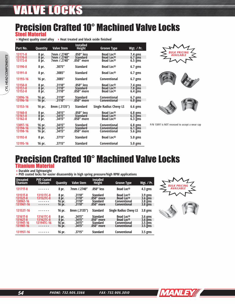
P/N 13097 is NOT recessed to accept a wear cap
Precision Crafted 10° Machined Valve Locks Steel MaterialHighest quality steel alloy Heat treated and black oxide finished
Precision Crafted 10° Machined Valve Locks Titanium MaterialDurable and lightweight PVD coated locks for easier disassembly in high spring pressure/high RPM applications
Installed Part No. Quantity Valve Stem Height Groove Type Wgt. / Pr. 13171-8 8 pr. 7mm /.2740” .050” less Bead Loc® 7.4 gms 13170-8 8 pr. 7mm /.2740” Standard Bead Loc® 6.7 gms 13172-8 8 pr. 7mm /.2740” .050” more Bead Loc® 6.5 gms 13190-8 8 pr. .3075” Standard Bead Loc® 6.7 gms 13191-8 8 pr. .3085” Standard Bead Loc® 6.7 gms
13193-16 16 pr. .3085” Standard Conventional 6.7 gms 13150-8 8 pr. .3110” .050” less Bead Loc® 7.4 gms 13151-8 8 pr. .3110” Standard Bead Loc® 7.0 gms 13152-8 8 pr. .3110” .050” more Bead Loc® 6.4 gms 13096-16 16 pr. .3110” Standard Conventional 6.7 gms 13196-16 16 pr. .3110” .050” more Conventional 6.0 gms 13153-16 16 pr. 8mm (.3135”) Standard Single Radius Chevy LS 6.6 gms 13160-8 8 pr. .3415” .050” less Bead Loc® 6.8 gms 13161-8 8 pr. .3415” Standard Bead Loc® 6.3 gms 13162-8 8 pr. .3415” .050” more Bead Loc® 6.3 gms 13097-16 16 pr. .3415” Standard Conventional 6.8 gms 13194-16 16 pr. .3415” Standard Conventional 6.1 gms 13198-16 16 pr. .3415” .050” more Conventional 5.6 gms 13192-8 8 pr. .3715” Standard Bead Loc® 5.0 gms 13195-16 16 pr. .3715” Standard Conventional 5.0 gms
BULK PRICING AVAILABLE
BULK PRICING AVAILABLE
Uncoated PVD Coated Installed Titanium Titanium Quantity Valve Stem Height Groove Type Wgt. / Pr. 13171T-8 - - - - - - 8 pr. 7mm /.2740” .050” less Bead Loc® 4.3 gms 13151T-8 13151TC-8 8 pr. .3110” Standard Bead Loc® 3.9 gms 13152T-8 13152TC-8 8 pr. .3110” .050” more Bead Loc® 3.6 gms 13096T-16 - - - - - - 16 pr. .3110” Standard Conventional 3.8 gms 13196T-16 - - - - - - 16 pr. .3110” .050” more Conventional 3.8 gms 13153T-16 - - - - - - 16 pr. 8mm (.3135”) Standard Single Radius Chevy LS 3.8 gms 13161T-8 13161TC-8 8 pr. .3415” Standard Bead Loc® 3.6 gms 13162T-8 13162TC-8 8 pr. .3415” .050” more Bead Loc® 3.6 gms 13194T-16 13194TC-16 16 pr. .3415” Standard Conventional 3.5 gms 13198T-16 - - - - - - 16 pr. .3415” .050” more Conventional 3.5 gms 13195T-16 - - - - - - 16 pr. .3715” Standard Conventional 3.5 gms
CYL
HEA
D C
OM
PON
ENTS
VALVE LOCKSVALVE LOCKS
55W W W . M A N L E Y P E R F O R M A N C E . C O M
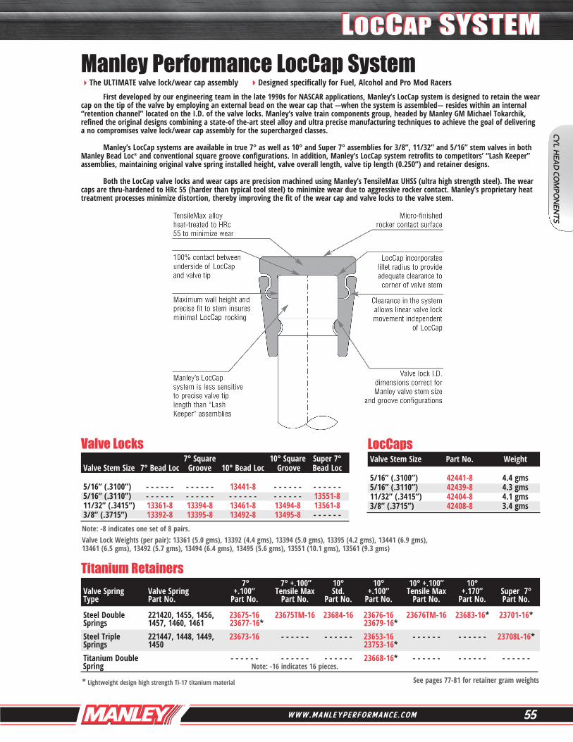
Manley Performance LocCap SystemThe ULTIMATE valve lock/wear cap assembly Designed specifically for Fuel, Alcohol and Pro Mod Racers First developed by our engineering team in the late 1990s for NASCAR applications, Manley’s LocCap system is designed to retain the wear cap on the tip of the valve by employing an external bead on the wear cap that —when the system is assembled— resides within an internal “retention channel” located on the I.D. of the valve locks. Manley’s valve train components group, headed by Manley GM Michael Tokarchik, refined the original designs combining a state-of the-art steel alloy and ultra precise manufacturing techniques to achieve the goal of delivering a no compromises valve lock/wear cap assembly for the supercharged classes.
Manley’s LocCap systems are available in true 7° as well as 10° and Super 7° assemblies for 3/8”, 11/32” and 5/16” stem valves in both Manley Bead Loc® and conventional square groove configurations. In addition, Manley’s LocCap system retrofits to competitors’ “Lash Keeper” assemblies, maintaining original valve spring installed height, valve overall length, valve tip length (0.250”) and retainer designs.
Both the LocCap valve locks and wear caps are precision machined using Manley’s TensileMax UHSS (ultra high strength steel). The wear caps are thru-hardened to HRc 55 (harder than typical tool steel) to minimize wear due to aggressive rocker contact. Manley’s proprietary heat treatment processes minimize distortion, thereby improving the fit of the wear cap and valve locks to the valve stem.
Valve Locks LocCaps
Titanium Retainers
Note: -8 indicates one set of 8 pairs. Valve Lock Weights (per pair): 13361 (5.0 gms), 13392 (4.4 gms), 13394 (5.0 gms), 13395 (4.2 gms), 13441 (6.9 gms),13461 (6.5 gms), 13492 (5.7 gms), 13494 (6.4 gms), 13495 (5.6 gms), 13551 (10.1 gms), 13561 (9.3 gms)
7° 7° +.100” 10° 10° 10° +.100” 10° Valve Spring Valve Spring +.100” Tensile Max Std. +.100” Tensile Max +.170” Super 7° Type Part No. Part No. Part No. Part No. Part No. Part No. Part No. Part No. Steel Double 221420, 1455, 1456, 23675-16 23675TM-16 23684-16 23676-16 23676TM-16 23683-16* 23701-16* Springs 1457, 1460, 1461 23677-16* 23679-16* Steel Triple 221447, 1448, 1449, 23673-16 - - - - - - - - - - - - 23653-16 - - - - - - - - - - - - 23708L-16* Springs 1450 23753-16* Titanium Double - - - - - - - - - - - - - - - - - - 23668-16* - - - - - - - - - - - - - - - - - - Spring Note: -16 indicates 16 pieces.
* Lightweight design high strength Ti-17 titanium material
7° Square 10° Square Super 7° Valve Stem Size 7° Bead Loc Groove 10° Bead Loc Groove Bead Loc 5/16” (.3100”) - - - - - - - - - - - - 13441-8 - - - - - - - - - - - - 5/16” (.3110”) - - - - - - - - - - - - - - - - - - - - - - - - 13551-8 11/32” (.3415”) 13361-8 13394-8 13461-8 13494-8 13561-8 3/8” (.3715”) 13392-8 13395-8 13492-8 13495-8 - - - - - -
Valve Stem Size Part No. Weight 5/16” (.3100”) 42441-8 4.4 gms 5/16” (.3110”) 42439-8 4.3 gms 11/32” (.3415”) 42404-8 4.1 gms 3/8” (.3715”) 42408-8 3.4 gms
See pages 77-81 for retainer gram weights
CYL HEA
D CO
MPO
NEN
TS
LOCCAP SYSTEMLOCCAP SYSTEM

56 P H O N E : 7 3 2 . 9 0 5 . 3 3 6 6 F A X : 7 3 2 . 9 0 5 . 3 0 1 0
Wear CapsThru-hardened 4140 alloy steel Special heat treatment to HRc 50-54 Non rotating caps afford less valve tip erosion
Wear resistant thru-hardened H-13 tool steel alloy Ideal titanium valve tip protection
Inserted Tips
Part No. Quantity .Description Minimum Tip Type A B C Weight 42263-8 8 pcs. .2165” stem valves (5.5mm) .095” Standard .090” .040” .300” 0.6 gms 42254-8 8 pcs. .2360” stem valves (6mm) .275” Non Rotating .235” .060” .385” 2.5 gms 42264-8 8 pcs. .2360” stem valves (6mm) .095” Standard .090” .040” .320” 0.6 gms 42100-8 8 pcs. .2740” stem valves (7mm) .250” Standard .225” .085” .425” 2.9 gms 42118-8 8 pcs. .2740” stem valves (7mm) .290” Non Rotating .270” .080” .385” 2.5 gms 42110-8 8 pcs. .2754” stem valves (7mm) .250” Standard .225” .085” .425” 2.9 gms 42101-16 16 pcs. .3085” stem valves (5/16”) .250” Standard .225” .080” .425” 2.6 gms 42139-8 8 pcs. .3110” stem valves (5/16”) .250” Standard .210” .080” .425” 2.4 gms 42300-8 8 pcs. .3110” stem valves (5/16”) .250” Non Rotating .210” .080” .425” 2.3 gms 42125-8 8 pcs. .3130” stem valves (8mm) .130” Standard .170” .080” .425” 2.1 gms 42104-16 16 pcs. .3415” stem valves (11/32”) .250” Standard .210” .080” .455” 2.7 gms 42301-8 8 pcs. .3415” stem valves (11/32”) .250” Non Rotating .210” .080” .455” 2.6 gms 42108-16 16 pcs. .3715” stem valves (3/8”) .220” Standard .175” .080” .485” 2.7 gms
TensileMax Wear CapsPrecision machined from TensileMax UHSS (Ultra High Strength Steel) Thru-hardened to HRc55 to minimize wear due to aggressive rocker contact Proprietary heat treatment processes minimize distortion
Part No. Quantity .Description Minimum Tip Type A B C Weight
42100TM-8 8 pcs. .2740” stem valves (7mm) .250” Standard .225” .085” .425” 3.0 gms 42139TM-8 8 pcs. .3110” stem valves (5/16”) .250” Standard .210” .080” .425” 2.6 gms 42104TM-16 16 pcs. .3415” stem valves (11/32”) .250” Standard .210” .080” .455” 2.9 gms
Part No. Quantity Material Description Knurl Diameter Post Length O.D. 42311-8 8 pcs. H-13 Fits .3085”-.3130” valves .183” .120” .316” 42105-8 8 pcs. H-13 Fits 11/32” valves .193” .120” .346”
CYL
HEA
D C
OM
PON
ENTS
WEAR CAPSWEAR CAPS
57W W W . M A N L E Y P E R F O R M A N C E . C O M
For use with any spring seat or seal cutter
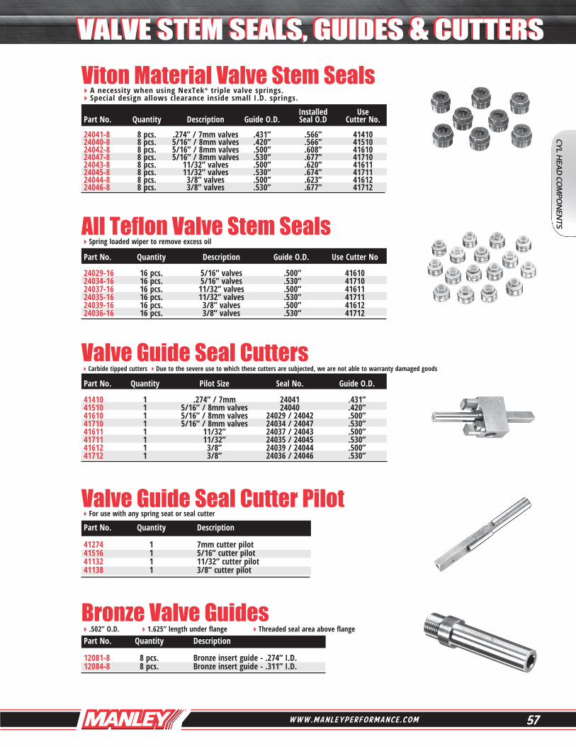
Valve Guide Seal CuttersCarbide tipped cutters Due to the severe use to which these cutters are subjected, we are not able to warranty damaged goods
All Teflon Valve Stem SealsSpring loaded wiper to remove excess oil
Viton Material Valve Stem SealsA necessity when using NexTek® triple valve springs. Special design allows clearance inside small I.D. springs.
Valve Guide Seal Cutter Pilot
Installed Use Part No. Quantity Description Guide O.D. Seal O.D Cutter No. 24041-8 8 pcs. .274” / 7mm valves .431” .566” 41410 24040-8 8 pcs. 5/16” / 8mm valves .420” .566” 41510 24042-8 8 pcs. 5/16” / 8mm valves .500” .608” 41610 24047-8 8 pcs. 5/16” / 8mm valves .530” .677” 41710 24043-8 8 pcs. 11/32” valves .500” .620” 41611 24045-8 8 pcs. 11/32” valves .530” .674” 41711 24044-8 8 pcs. 3/8” valves .500” .623” 41612 24046-8 8 pcs. 3/8” valves .530” .677” 41712
Part No. Quantity Description Guide O.D. Use Cutter No 24029-16 16 pcs. 5/16” valves .500” 41610 24034-16 16 pcs. 5/16” valves .530” 41710 24037-16 16 pcs. 11/32” valves .500” 41611 24035-16 16 pcs. 11/32” valves .530” 41711 24039-16 16 pcs. 3/8” valves .500” 41612 24036-16 16 pcs. 3/8” valves .530” 41712
Part No. Quantity Pilot Size Seal No. Guide O.D. 41410 1 .274” / 7mm 24041 .431” 41510 1 5/16” / 8mm valves 24040 .420” 41610 1 5/16” / 8mm valves 24029 / 24042 .500” 41710 1 5/16” / 8mm valves 24034 / 24047 .530” 41611 1 11/32” 24037 / 24043 .500” 41711 1 11/32” 24035 / 24045 .530” 41612 1 3/8” 24039 / 24044 .500” 41712 1 3/8” 24036 / 24046 .530”
Part No. Quantity Description 41274 1 7mm cutter pilot 41516 1 5/16” cutter pilot 41132 1 11/32” cutter pilot 41138 1 3/8” cutter pilot
Bronze Valve Guides.502” O.D. 1.625” length under flange Threaded seal area above flange Part No. Quantity Description 12081-8 8 pcs. Bronze insert guide - .274” I.D. 12084-8 8 pcs. Bronze insert guide - .311” I.D.
CYL HEA
D CO
MPO
NEN
TS
VALVE STEM SEALS, GUIDES & CUTTERSVALVE STEM SEALS, GUIDES & CUTTERS

58 P H O N E : 7 3 2 . 9 0 5 . 3 3 6 6 F A X : 7 3 2 . 9 0 5 . 3 0 1 0
Professional Rocker Arm Screw-In Studs8740 material with 190,000 psi tensile strength Rolled threads Large radii Flat poly lock surface
Street Master Rocker Arm Screw-In Studs
Special chrome moly hex material Heat treated and black oxide Set screws and allen wrench included
Special maxalloy steel Rolled threads
Part No. Quantity Description 42107-16 16 pcs. All 3/8” stud Chevys, Fords, Pontiacs 42112-16 16 pcs. All 7/16” stud Chevys and Fords (.580” Body Diameter)
Upper D imensions Part No. Quantity Description Threads A B C D 42106-16 16 pcs. SB Chevy & Ford 3/8” 2.560” .690” .840” 1.030” 42147-16 16 pcs. SB Chevy & Ford with poly locks 3/8” 2.420” .690” .920” .810” 42103-16 16 pcs. SB Chevy, BB Chevy & Ford 7/16” 2.550” .790” .890” .870”
BULK PRICING AVAILABLE
BULK PRICING AVAILABLE
Roller Stud Upper Dimensions Part No. Quantity Application Rockers Girdles Threads A B C D 42276-16 16 pcs. SB Chevy & Ford Yes No 3/8” 2.425” .670” .945” .810” 42277-16 16 pcs. SB Chevy & Ford Yes No 7/16” 2.440” .660” .890” .890” 42287-16 16 pcs. SB Chevy Yes Yes 7/16” 2.850” .750” 1.300” .800” w/ 18° head 42288-16 16 pcs. SB & BB Chevy Yes Yes 7/16” 2.810” .740” 1.020” 1.050” 42290-8 8 pcs. SB & BB Chevy Yes Yes 7/16” 2.810” .740” 1.020” 1.050” 42287-16 16 pcs. BB Chevy Yes Yes 7/16” 2.850” .750” 1.300” .800” 42278-16 16 pcs. BB Chevy No No 7/16” 2.580” .820” .900” .860” 42256-16 16 pcs. BB Chevy Yes Yes 7/16” 3.200” .850” 1.550” .800” w/ tall springs 42266-16 16 pcs. BB Chevy Yes No 7/16” 2.600” .775” .885” 1.000” Mark V w/ 3/8” lower threads converting to Mark IV heads 42293-8 8 pcs. BB Chevy Yes Yes 7/16” 3.300” 1.300” 1.000” 1.000” w/ Dart aluminum
Highest quality steel Heat treated Long slots to avoid stud interference Kits include oil grooved rocker balls and nutsThese rockers are the non “self-aligning” type used from 1955 to 1989.
Small Block Chevrolet Stamped Steel Rocker Arm Kits
ROCKER ARM KIT COMPONENTSNote: Individual rockers only are sold as -8, and rocker balls and rocker nuts are sold as -16. Kits include only 8 pieces of each part.
Kit Rocker Ball Nut 43140 43141-8 43142-16 43143-16 43150 43151-8 43142-16 43143-16
Part No. Quantity Description Stud Diameter 43140 1 set for 1 head Small Block - Long Slot 1.5 Ratio 3/8” 43150 1 set for 1 head Small Block - Long Slot 1.6 Ratio 3/8”
Professional Rocker Arm Adjusting Nuts
CYL
HEA
D C
OM
PON
ENTS
ROCKER STUDSROCKER STUDS
59W W W . M A N L E Y P E R F O R M A N C E . C O M
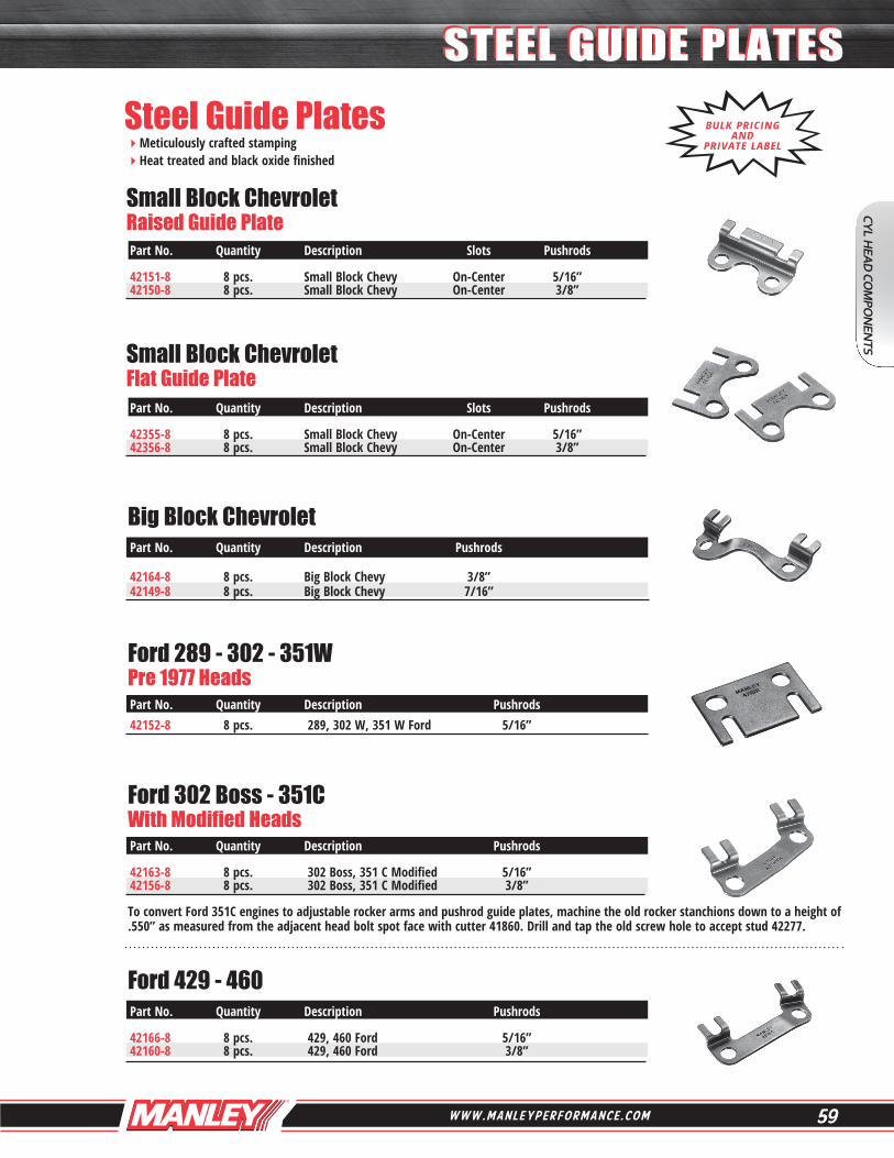
Meticulously crafted stamping Heat treated and black oxide finished
To convert Ford 351C engines to adjustable rocker arms and pushrod guide plates, machine the old rocker stanchions down to a height of .550” as measured from the adjacent head bolt spot face with cutter 41860. Drill and tap the old screw hole to accept stud 42277.
Ford 429 - 460
Ford 302 Boss - 351C With Modified Heads
Ford 289 - 302 - 351W Pre 1977 Heads
Small Block Chevrolet Flat Guide Plate
Small Block Chevrolet Raised Guide Plate
Big Block Chevrolet
Part No. Quantity Description Slots Pushrods 42151-8 8 pcs. Small Block Chevy On-Center 5/16” 42150-8 8 pcs. Small Block Chevy On-Center 3/8”
Part No. Quantity Description Slots Pushrods 42355-8 8 pcs. Small Block Chevy On-Center 5/16” 42356-8 8 pcs. Small Block Chevy On-Center 3/8”
Part No. Quantity Description Pushrods 42164-8 8 pcs. Big Block Chevy 3/8” 42149-8 8 pcs. Big Block Chevy 7/16”
Part No. Quantity Description Pushrods 42152-8 8 pcs. 289, 302 W, 351 W Ford 5/16”
Part No. Quantity Description Pushrods 42163-8 8 pcs. 302 Boss, 351 C Modified 5/16” 42156-8 8 pcs. 302 Boss, 351 C Modified 3/8”
Part No. Quantity Description Pushrods 42166-8 8 pcs. 429, 460 Ford 5/16” 42160-8 8 pcs. 429, 460 Ford 3/8”
BULK PRICING AND
PRIVATE LABEL
Steel Guide Plates
CYL HEA
D CO
MPO
NEN
TS
STEEL GUIDE PLATESSTEEL GUIDE PLATES
60 P H O N E : 7 3 2 . 9 0 5 . 3 3 6 6 F A X : 7 3 2 . 9 0 5 . 3 0 1 0
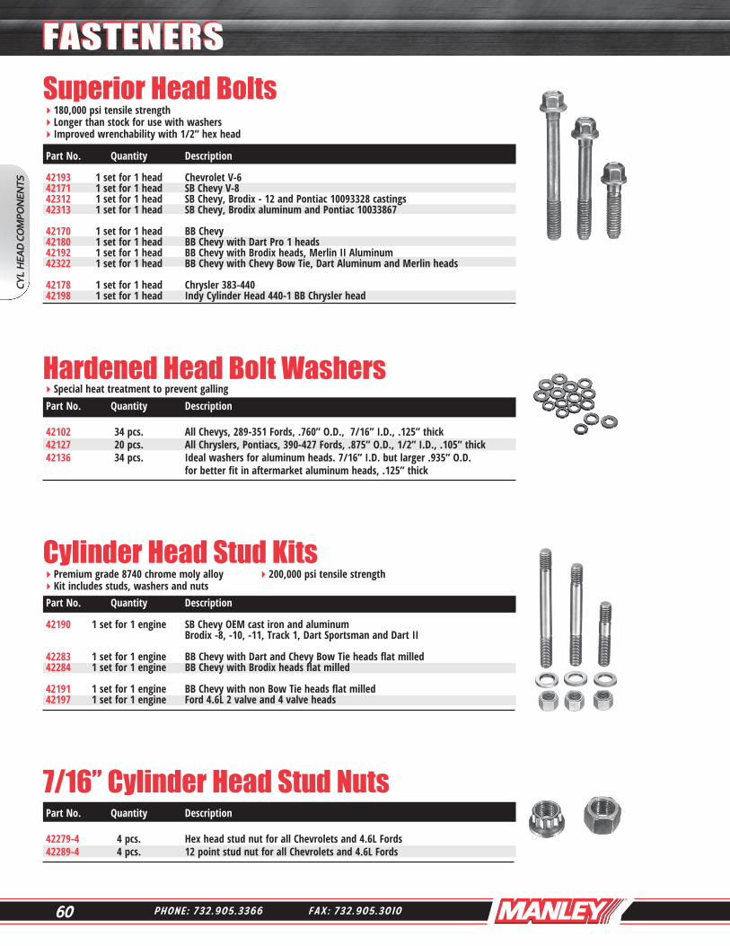
Superior Head Bolts180,000 psi tensile strength Longer than stock for use with washers Improved wrenchability with 1/2” hex head
Special heat treatment to prevent galling
Premium grade 8740 chrome moly alloy 200,000 psi tensile strength Kit includes studs, washers and nuts
Cylinder Head Stud Kits
Hardened Head Bolt Washers Part No. Quantity Description 42102 34 pcs. All Chevys, 289-351 Fords, .760” O.D., 7/16” I.D., .125” thick 42127 20 pcs. All Chryslers, Pontiacs, 390-427 Fords, .875” O.D., 1/2” I.D., .105” thick 42136 34 pcs. Ideal washers for aluminum heads. 7/16” I.D. but larger .935” O.D. for better fit in aftermarket aluminum heads, .125” thick
Part No. Quantity Description 42193 1 set for 1 head Chevrolet V-6 42171 1 set for 1 head SB Chevy V-8 42312 1 set for 1 head SB Chevy, Brodix - 12 and Pontiac 10093328 castings 42313 1 set for 1 head SB Chevy, Brodix aluminum and Pontiac 10033867 42170 1 set for 1 head BB Chevy 42180 1 set for 1 head BB Chevy with Dart Pro 1 heads 42192 1 set for 1 head BB Chevy with Brodix heads, Merlin II Aluminum 42322 1 set for 1 head BB Chevy with Chevy Bow Tie, Dart Aluminum and Merlin heads 42178 1 set for 1 head Chrysler 383-440 42198 1 set for 1 head Indy Cylinder Head 440-1 BB Chrysler head
Part No. Quantity Description 42190 1 set for 1 engine SB Chevy OEM cast iron and aluminum Brodix -8, -10, -11, Track 1, Dart Sportsman and Dart II 42283 1 set for 1 engine BB Chevy with Dart and Chevy Bow Tie heads flat milled 42284 1 set for 1 engine BB Chevy with Brodix heads flat milled 42191 1 set for 1 engine BB Chevy with non Bow Tie heads flat milled 42197 1 set for 1 engine Ford 4.6L 2 valve and 4 valve heads
CYL
HEA
D C
OM
PON
ENTS
FASTENERSFASTENERS
7/16” Cylinder Head Stud Nuts Part No. Quantity Description 42279-4 4 pcs. Hex head stud nut for all Chevrolets and 4.6L Fords 42289-4 4 pcs. 12 point stud nut for all Chevrolets and 4.6L Fords
61W W W . M A N L E Y P E R F O R M A N C E . C O M
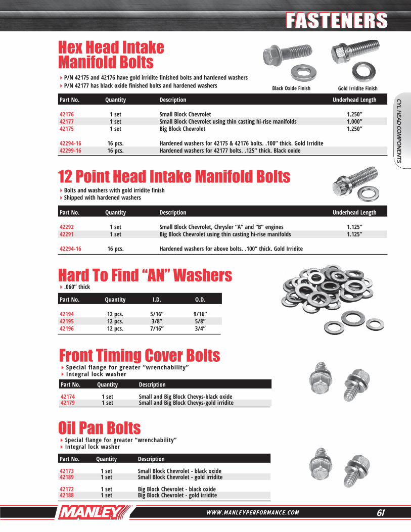
Hex Head IntakeManifold BoltsP/N 42175 and 42176 have gold irridite finished bolts and hardened washers P/N 42177 has black oxide finished bolts and hardened washers
Part No. Quantity Description Underhead Length 42176 1 set Small Block Chevrolet 1.250” 42177 1 set Small Block Chevrolet using thin casting hi-rise manifolds 1.000” 42175 1 set Big Block Chevrolet 1.250” 42294-16 16 pcs. Hardened washers for 42175 & 42176 bolts. .100” thick. Gold Irridite 42299-16 16 pcs. Hardened washers for 42177 bolts. .125” thick. Black oxide
Black Oxide Finish Gold Irridite Finish
Bolts and washers with gold irridite finish Shipped with hardened washers
12 Point Head Intake Manifold Bolts
Part No. Quantity Description Underhead Length 42292 1 set Small Block Chevrolet, Chrysler “A” and “B” engines 1.125” 42291 1 set Big Block Chevrolet using thin casting hi-rise manifolds 1.125” 42294-16 16 pcs. Hardened washers for above bolts. .100” thick. Gold Irridite
Hard To Find “AN” Washers.060” thick
Part No. Quantity I.D. O.D. 42194 12 pcs. 5/16” 9/16” 42195 12 pcs. 3/8” 5/8” 42196 12 pcs. 7/16” 3/4”
CYL HEA
D CO
MPO
NEN
TS
FASTENERSFASTENERS
Front Timing Cover BoltsSpecial flange for greater “wrenchability” Integral lock washer
Part No. Quantity Description 42174 1 set Small and Big Block Chevys-black oxide 42179 1 set Small and Big Block Chevys-gold irridite
Oil Pan BoltsSpecial flange for greater “wrenchability” Integral lock washer
Part No. Quantity Description 42173 1 set Small Block Chevrolet - black oxide 42189 1 set Small Block Chevrolet - gold irridite 42172 1 set Big Block Chevrolet - black oxide 42188 1 set Big Block Chevrolet - gold irridite
62 P H O N E : 7 3 2 . 9 0 5 . 3 3 6 6 F A X : 7 3 2 . 9 0 5 . 3 0 1 0
Installed / Open Pressure
Component Titanium TensileMax I.D. Spring Seat Code Retainers Description Retainers Locators O.D. I.D. Thickness Cutter A 23675-16 7° ( +.100 for 7° LocCap ) 23675TM-16 7° ( +.100 ) 42347-16 1.535 .570 .062 41856 23677-16 7° ( +.100 for 7° LocCap ) TI-17 Alloy 42318-16 1.610 .570 .062 41857 23684-16 10° Std. Installed 42344-16 1.535 .635 .035 41835 23676-16 10° ( +.100 ) 23676TM-16 10° ( +.100 ) 42335-16 1.535 .635 .062 41835 23679-16 10° ( +.100 ) Lightweight TI-17 Alloy 42120-16 1.610 .635 .062 41855 23683-16 10° ( +.170 ) Lightweight TI-17 Alloy 23701-16 Super 7° Lightweight TI-17 Alloy
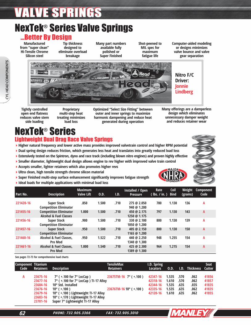
Higher natural frequency and lower active mass provides improved valvetrain control and higher RPM potentialDual spring design reduces friction, which generates less heat and translates into greatly reduced load lossExtensively tested on the Spintron, dyno and race track (including blown nitro engines) and proven highly effectiveSmaller diameter, lightweight dual design allows engine to rev higher with improved valve train controlAccepts smaller, lighter retainers which also promotes higher revsUltra clean, high tensile strength chrome silicon materialSuper Finished multi-step surface enhancement significantly improves fatigue strengthIdeal loads for multiple applications with minimal load loss
See pages 72-73 for comprehensive load charts
Maximum Rate Coil Weight Component Part No. Description Valve Lift O.D. I.D. . ( lbs. / in. ) Bind (grams) Code
221420-16 Super Stock .850 1.500 .710 275 @ 2.050 780 1.130 136 A Competition Eliminator 940 @ 1.200 221455-16 Competition Eliminator 1.000 1.500 .710 450 @ 2.175 797 1.130 143 A Alcohol & Fuel Classes 1250 @ 1.175 221456-16 Super Stock .900 1.500 .710 330 @ 2.100 800 1.130 139 A Competition Eliminator 1050 @ 1.200 221457-16 Super Stock .950 1.500 .710 405 @ 2.150 800 1.130 150 A Competition Eliminator 1165 @ 1.200 221460-16 Alcohol & Fuel Classes, .950 1.522 .710 440 @ 2.250 948 1.255 154 A Pro Mod 1340 @ 1.300 221461-16 Alcohol & Fuel Classes, 1.000 1.540 .710 425 @ 2.300 964 1.215 154 A Pro Mod 1389 @ 1.300
NexTek® Series Lightweight Dual Drag Race Valve Springs
CYL
HEA
D C
OM
PON
ENTS
VALVE SPRINGSVALVE SPRINGSNexTek® Series Valve Springs ...Better By Design
Manufacturedfrom “super clean”Hi-Tensile Chrome
Silicon steel
Tip thicknessdesigned to
eliminate overloadbreakage
Many part numbersavailable fully
polished orSuper Finished
Shot-peened toMIL spec formaximum fatigue life
Computer-aided modelingor designs minimizes
valve bounce and valvegear separation
Tightly controlledopen end flatness
reduces valve stemside loading
Proprietarymulti-step heat
treating minimizesload loss
Optimized “Select Size Fitting” betweenouter and inner springs to maximize
harmonic dampening and reduce heatgenerated during operation
Many offerings are a damperlessdesign which eliminates
unnecessary damper weightand reduces retainer wear
Nitro F/CDriver:Jonnie Lindberg
63W W W . M A N L E Y P E R F O R M A N C E . C O M
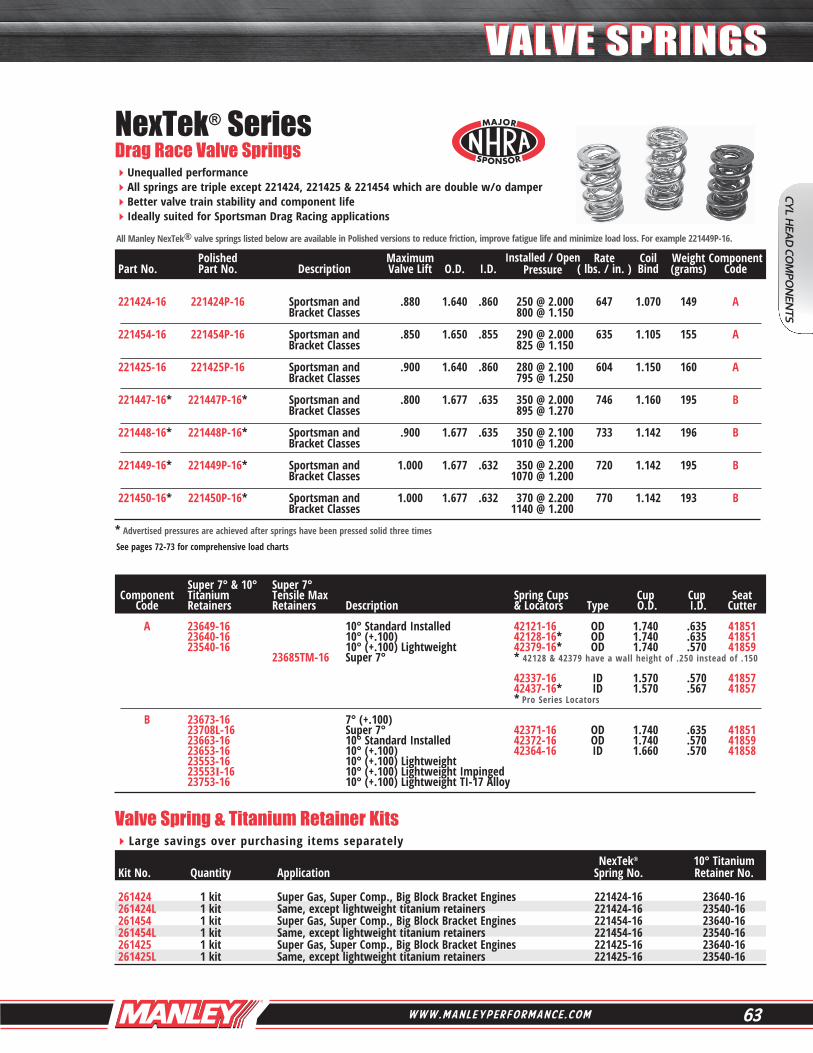
Unequalled performance All springs are triple except 221424, 221425 & 221454 which are double w/o damper Better valve train stability and component life Ideally suited for Sportsman Drag Racing applications
NexTek® Series Drag Race Valve Springs
Valve Spring & Titanium Retainer KitsLarge savings over purchasing items separately
Super 7° & 10° Super 7° Component Titanium Tensile Max Spring Cups Cup Cup Seat Code Retainers Retainers Description & Locators Type O.D. I.D. Cutter A 23649-16 10° Standard Installed 42121-16 OD 1.740 .635 41851 23640-16 10° (+.100) 42128-16* OD 1.740 .635 41851 23540-16 10° (+.100) Lightweight 42379-16* OD 1.740 .570 41859 23685TM-16 Super 7° * 42128 & 42379 have a wall height of .250 instead of .150 42337-16 ID 1.570 .570 41857 42437-16* ID 1.570 .567 41857 * Pro Series Locators B 23673-16 7° (+.100) 23708L-16 Super 7° 42371-16 OD 1.740 .635 41851 23663-16 10° Standard Installed 42372-16 OD 1.740 .570 41859 23653-16 10° (+.100) 42364-16 ID 1.660 .570 41858 23553-16 10° (+.100) Lightweight 23553I-16 10° (+.100) Lightweight Impinged 23753-16 10° (+.100) Lightweight TI-17 Alloy
All Manley NexTek® valve springs listed below are available in Polished versions to reduce friction, improve fatigue life and minimize load loss. For example 221449P-16.
* Advertised pressures are achieved after springs have been pressed solid three times
Installed / Open Pressure
Polished Maximum Rate Coil Weight Component Part No. Part No. Description Valve Lift O.D. I.D. . ( lbs. / in. ) Bind (grams) Code 221424-16 221424P-16 Sportsman and .880 1.640 .860 250 @ 2.000 647 1.070 149 A Bracket Classes 800 @ 1.150 221454-16 221454P-16 Sportsman and .850 1.650 .855 290 @ 2.000 635 1.105 155 A Bracket Classes 825 @ 1.150 221425-16 221425P-16 Sportsman and .900 1.640 .860 280 @ 2.100 604 1.150 160 A Bracket Classes 795 @ 1.250 221447-16* 221447P-16* Sportsman and .800 1.677 .635 350 @ 2.000 746 1.160 195 B Bracket Classes 895 @ 1.270 221448-16* 221448P-16* Sportsman and .900 1.677 .635 350 @ 2.100 733 1.142 196 B Bracket Classes 1010 @ 1.200 221449-16* 221449P-16* Sportsman and 1.000 1.677 .632 350 @ 2.200 720 1.142 195 B Bracket Classes 1070 @ 1.200 221450-16* 221450P-16* Sportsman and 1.000 1.677 .632 370 @ 2.200 770 1.142 193 B Bracket Classes 1140 @ 1.200
NexTek® 10° Titanium Kit No. Quantity Application Spring No. Retainer No. 261424 1 kit Super Gas, Super Comp., Big Block Bracket Engines 221424-16 23640-16 261424L 1 kit Same, except lightweight titanium retainers 221424-16 23540-16 261454 1 kit Super Gas, Super Comp., Big Block Bracket Engines 221454-16 23640-16 261454L 1 kit Same, except lightweight titanium retainers 221454-16 23540-16 261425 1 kit Super Gas, Super Comp., Big Block Bracket Engines 221425-16 23640-16 261425L 1 kit Same, except lightweight titanium retainers 221425-16 23540-16
See pages 72-73 for comprehensive load charts
CYL HEA
D CO
MPO
NEN
TS
VALVE SPRINGSVALVE SPRINGS

64 P H O N E : 7 3 2 . 9 0 5 . 3 3 6 6 F A X : 7 3 2 . 9 0 5 . 3 0 1 0
No degradation of spring pressure in the later stages of a race Specially processed premium-grade chrome silicon that is virtually free of impurities or surface irregularities NexTek
® Series valve springs have been tested by leading engine builders and are confirmed to be the best performing
valve springs on the market today
NexTek® Series Drag Race, Oval Track & Endurance Valve Springs
See page 72-73 for comprehensive load charts
Please refer to opposite page 65 for the appropriate fitting retainers and spring cups. Match the component codes listed to select the correct parts.
Polished Super Finished Maximum Installed / Open Rate Coil Weight Component Part No. Part No. Part No. Description Valve Lift O.D. I.D. Pressure ( lbs. / in. ) Bind (grams) Code 221432-16 - - - - - - - - - - - - - - - - Late Model Stock .630 1.530 .750 150 @ 1.900 435 1.170 152 A w/ Flat Tappet Double With Damper 425 @ 1.270 - - - - - - - - 221440P-16 - - - - - - - - Solid Roller .700 1.570 .760 255 @ 2.000 534 1.190 165 B Double With Damper 630 @ 1.300 - - - - - - - - 221441P-16 - - - - - - - - Solid Roller .730 1.570 .750 280 @ 2.030 575 1.215 170 C Double With Damper 700 @ 1.300 - - - - - - - - 221442-16 - - - - - - - - Solid Roller .750 1.560 .812 260 @ 2.000 533 1.200 155 D Double Without Damper 660 @ 1.250 221443-16 221443P-16 - - - - - - - - Solid Roller .730 1.580 .832 235 @ 1.950 535 1.170 150 E Double Without Damper 610 @ 1.250 221444-16 221444P-16 - - - - - - - - Solid Roller .750 1.610 .842 235 @ 2.050 546 1.220 161 F Double Without Damper 645 @ 1.300 - - - - - - - - 221445P-16 - - - - - - - - Solid Roller .800 1.620 .852 280 @ 2.050 500 1.200 168 G Double Without Damper 680 @ 1.250 - - - - - - - - - - - - - - - - 221446SF-16 Solid Roller .800 1.400 .700 240 @ 2.050 575 1.150 125 H Double Without Damper 700 @ 1.250
- - - - - - - - - - - - - - - - 221452SF-16 Solid Roller .825 1.550 .800 250 @ 2.025 618 1.150 144 I Double Without Damper 750 @ 1.200
CYL
HEA
D C
OM
PON
ENTS
VALVE SPRINGSVALVE SPRINGS

65W W W . M A N L E Y P E R F O R M A N C E . C O M
SUFFIX CODE: I : Impinged L : Lightweight LI : Lightweight and Impinged LTM : Lightweight TensileMax TM: TensileMax TS: Tool Steel
Ancillary ComponentsFor Springs On Page 64
* Pro Series Locators
Super 7° Super 7° Super 7° & 10° Lightweight +.050 Super 7° H-13 Component Titanium Titanium Titanium TensileMax Tool Steel Spring Cups Cup Cup Cup Seat Code Retainers Retainers Retainers Retainers Retainers & Locators Type O.D. I.D. Thickness Cutter A 23707-16 (Super 7°) 23707TM-16 23650TS-16 42330-16 ID 1.535 .635 .062 41835 23644-16 (10° Ti Std.) (10° +.100) 42326-16* ID 1.535 .570 .062 41856 23650-16 (10° Ti +.100) 42426-16* ID 1.535 .567 .062 41856 42466-16* ID 1.535 .567 .045 41856 B 23705L-16 23706L-16 23705TM-16 23650TS-16 42331-16 ID 1.530 .570 .062 41856 23705LI-16 23706LI-16 23705LTM-16 (10° +.100) 23644-16 (10° Ti Std.) 23650-16 (10° Ti +.100) C 23672-16 (Super 7°) 23672L-16 23672TM-16 23647TS-16 42330-16 ID 1.535 .635 .062 41835 23672I-16 (Super 7°) (10° +.100) 42326-16 ID 1.535 .570 .062 41856 23672TS-16 42426-16* ID 1.535 .567 .062 41856 23647-16 (10° Ti +.100) (Super 7°) 42466-16* ID 1.535 .567 .045 41856 D 23682-16 (Super 7°) 23682L-16 23682TM-16 23643TS-16 42343-16 ID 1.550 .570 .062 41856 23682I-16 (Super 7°) 23682LI-16 (10° +.100) 42443-16* ID 1.550 .567 .062 41856 23682TS-16 23643-16 (10° Ti +.100) (Super 7°) E 23681-16 (Super 7°) 23681L-16 23691-16 23648TS-16 42370-16 OD 1.687 .570 .062 41858 23681I-16 (Super 7°) 23681LI-16 (10° +.100) 42369-16 ID 1.570 .635 .062 41856 23681TS-16 42373-16 ID 1.570 .570 .062 41856 23648-16 (10° Ti +.100) (Super 7°) 42573-16* ID 1.570 .567 .062 41856 42438-16* ID 1.570 .567 .045 41856
F 23681-16 (Super 7°) 23681L-16 23691-16 23648TS-16 42365-16 OD 1.740 .570 .062 41859 23681I-16 (Super 7°) 23681LI-16 (10° +.100) 42367-16 ID 1.610 .570 .062 41857 23681TS-16 42368-16 ID 1.610 .635 .062 41855 23648-16 (10° Ti +.100) (Super 7°)
G 23685-16 (Super 7°) 23685L-16 23685TM-16 42342-16 ID 1.610 .570 .062 41857 23685I-16 (Super 7°) 23685LI-16
H 23746L-16 23746TM-16 23746TS-16 42446-16* ID 1.410 .567 .062 41850 (Super 7°) 23747TS-16 (10° +.100)
I 23702L-16 23702LTM-16 23702TS-16 42402-16* ID 1.540 .567 .062 41856 (Super 7°)
CYL HEA
D CO
MPO
NEN
TS
VALVE SPRINGSVALVE SPRINGS
66 P H O N E : 7 3 2 . 9 0 5 . 3 3 6 6 F A X : 7 3 2 . 9 0 5 . 3 0 1 0
Please refer to opposite page 67 for the appropriate fitting retainers and spring cups. Match the component codes listed to select the correct parts.
See page 74 for comprehensive load charts
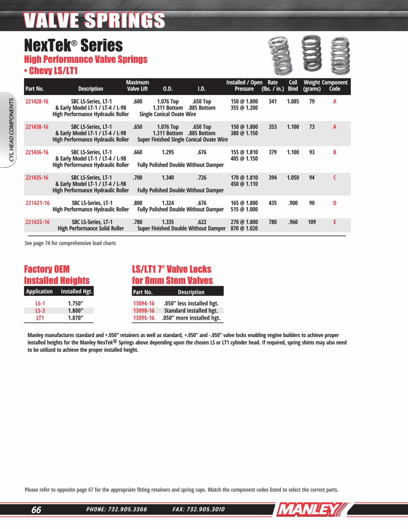
NexTek® Series High Performance Valve Springs• Chevy LS/LT1 Maximum Installed / Open Rate Coil Weight Component Part No. Description Valve Lift O.D. I.D. Pressure (lbs. / in.) Bind (grams) Code 221428-16 SBC LS-Series, LT-1 .600 1.076 Top .650 Top 150 @ 1.800 341 1.085 79 A & Early Model LT-1 / LT-4 / L-98 1.311 Bottom .885 Bottom 355 @ 1.200 High Performance Hydraulic Roller Single Conical Ovate Wire
221438-16 SBC LS-Series, LT-1 .650 1.076 Top .650 Top 150 @ 1.800 353 1.100 73 A & Early Model LT-1 / LT-4 / L-98 1.311 Bottom .885 Bottom 380 @ 1.150 High Performance Hydraulic Roller Super Finished Single Conical Ovate Wire
221436-16 SBC LS-Series, LT-1 .660 1.295 .676 155 @ 1.810 379 1.100 93 B & Early Model LT-1 / LT-4 / L-98 405 @ 1.150 High Performance Hydraulic Roller Fully Polished Double Without Damper
221435-16 SBC LS-Series, LT-1 .700 1.340 .726 170 @ 1.810 394 1.050 94 C & Early Model LT-1 / LT-4 / L-98 450 @ 1.110 High Performance Hydraulic Roller Fully Polished Double Without Damper 221421-16 SBC LS-Series, LT-1 .800 1.324 .676 165 @ 1.800 435 .900 90 D High Performance Hydraulic Roller Fully Polished Double Without Damper 515 @ 1.000
221422-16 SBC LS-Series, LT-1 .780 1.335 .622 270 @ 1.800 780 .960 109 E High Performance Solid Roller Super Finished Double Without Damper 870 @ 1.020
CYL
HEA
D C
OM
PON
ENTS
VALVE SPRINGSVALVE SPRINGS
Factory OEMInstalled Heights
Application Installed Hgt.
LS-1 1.750” LS-3 1.800” LT1 1.870”
LS/LT1 7° Valve Locks for 8mm Stem Valves
Part No. Description
13094-16 .050” less installed hgt.13098-16 Standard installed hgt.13095-16 .050” more installed hgt.
Manley manufactures standard and +.050” retainers as well as standard, +.050” and -.050” valve locks enabling engine builders to achieve proper installed heights for the Manley NexTek® Springs above depending upon the chosen LS or LT1 cylinder head. If required, spring shims may also need to be utilized to achieve the proper installed height.

67W W W . M A N L E Y P E R F O R M A N C E . C O M
Ancillary Components For Springs On Page 66
Note: New part numbers are BOLD & ITALICIZED
Large savings over purchasing items separately
Component Retainer Spring Cup Cup Cup Cup Seat Code Part No. Description Part No. Type O.D. I.D. Thickness Cutter
A 23620-16 7° Steel for Manley 13098 or factory LS valve lock and factory spring seat 23606TS-16 10° H-13 Tool Steel Standard Height for Manley 13153 valve lock 23622-16 7° Titanium for Manley 13098 or factory LS valve lock and factory spring seat 23625-16 7° Titanium +.050 for Manley 13098 or factory LS valve lock and factory spring seat 23626-16 7° Titanium +.050 for early model LT-1 and standard type valve lock
42338-16 ID 1.290 .505 .035 None 42336-16 ID 1.290 .505 .062 None 42349-16 ID 1.290 .570 .062 41850 B 23621-16 7° Steel +.050 for Manley 13098 or factory LS valve lock 23616TS-16 10° H-13 Tool Steel +.050 for Manley 13153 valve lock 23617-16 7° Titanium for Manley 13098 or factory LS valve lock 23623-16 7° Titanium +.050 for Manley 13098 or factory LS valve lock 23624-16 7° Titanium +.050 for early model LT-1 and standard type valve lock
42334-16 ID 1.270 .505 .035 None 42124-16 ID 1.270 .570 .062 41850 42138-16 ID 1.270 .505 .062 None
C 23610-16 7° Steel +.050 for Manley 13098 or factory LS valve lock 23611-16 7° Titanium +.050 for Manley 13098 or factory LS valve lock 23615TS-16 10° H-13 Tool Steel Standard Height for early model LT-1
42348-16 ID 1.320 .505 .035 None 42135-16 ID 1.320 .567 .035 None
D 23618-16 7° Titanium + .050 for Manley 13098 or factory LS valve lock
42117-16 ID 1.300 .505 .035 None 42130-16 ID 1.300 .567 .035 None
E 23619-16 10° Titanium + .050 for Manley 13153 valve lock
42129-16 ID 1.310 .505 .035 None 42131-16 ID 1.310 .567 .035 None
LS/LT1 Valve Spring Kits
CYL HEA
D CO
MPO
NEN
TS
VALVE SPRINGSVALVE SPRINGS
See page 74 for comprehensive load charts
NexTek® 7° Steel I.D. Valve Spring 7° Machined Viton Valve Kit No. Application / Max. Lift Spring No. Retainer No. Locator No. Valve Lock No. Stem Seals No. 26382038KS LS / .600” 221438-16 23620-16 42338-16 13098-16 24042-16 26362134KS LS / .660” 221436-16 23621-16 42334-16 13098-16 24042-16
NexTek® 7° Titanium I.D. Valve Spring 7° Machined Viton Valve Kit No. Application / Max. Lift Spring No. Retainer No. Locator No. Valve Lock No. Stem Seals No. 26382538KS LS / .650” 221438-16 23625-16 42338-16 13098-16 24042-16 26361734KLS LS / .560” - LT1 / .660” 221436-16 23617-16 42334-16 13094-16 24042-16 26362334KS LS / .660” 221436-16 23623-16 42334-16 13098-16 24042-16
NexTek® 10° Tool Steel I.D. Valve Spring 10° Machined Viton Valve Kit No. Application / Max. Lift Spring No. Retainer No. Locator No. Valve Lock No. Stem Seals No. 26380638KS LS / .600” 221438-16 23606TS-16 42338-16 13153-16 24042-16 26361634KS LS / .660” 221436-16 23616TS-16 42334-16 13153-16 24042-16
Note: Max. lift figures above may vary depending upon the cylinder head and installed height.
68 P H O N E : 7 3 2 . 9 0 5 . 3 3 6 6 F A X : 7 3 2 . 9 0 5 . 3 0 1 0
CYL
HEA
D C
OM
PON
ENTS
VALVE SPRINGSVALVE SPRINGS
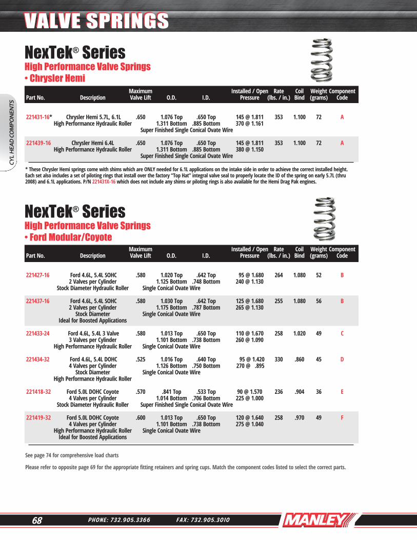
* These Chrysler Hemi springs come with shims which are ONLY needed for 6.1L applications on the intake side in order to achieve the correct installed height. Each set also includes a set of piloting rings that install over the factory “Top Hat” integral valve seal to properly locate the ID of the spring on early 5.7L (thru 2008) and 6.1L applications. P/N 221431X-16 which does not include any shims or piloting rings is also available for the Hemi Drag Pak engines.
Please refer to opposite page 69 for the appropriate fitting retainers and spring cups. Match the component codes listed to select the correct parts.
See page 74 for comprehensive load charts
NexTek® Series High Performance Valve Springs• Chrysler Hemi Maximum Installed / Open Rate Coil Weight Component Part No. Description Valve Lift O.D. I.D. Pressure (lbs. / in.) Bind (grams) Code 221431-16* Chrysler Hemi 5.7L, 6.1L .650 1.076 Top .650 Top 145 @ 1.811 353 1.100 72 A High Performance Hydraulic Roller 1.311 Bottom .885 Bottom 370 @ 1.161 Super Finished Single Conical Ovate Wire
221439-16 Chrysler Hemi 6.4L .650 1.076 Top .650 Top 145 @ 1.811 353 1.100 72 A High Performance Hydraulic Roller 1.311 Bottom .885 Bottom 380 @ 1.150 Super Finished Single Conical Ovate Wire
NexTek® Series High Performance Valve Springs• Ford Modular/Coyote Maximum Installed / Open Rate Coil Weight Component Part No. Description Valve Lift O.D. I.D. Pressure (lbs. / in.) Bind (grams) Code
221427-16 Ford 4.6L, 5.4L SOHC .580 1.020 Top .642 Top 95 @ 1.680 264 1.080 52 B 2 Valves per Cylinder 1.125 Bottom .748 Bottom 240 @ 1.130 Stock Diameter Hydraulic Roller Single Conical Ovate Wire
221437-16 Ford 4.6L, 5.4L SOHC .580 1.030 Top .642 Top 125 @ 1.680 255 1.080 56 B 2 Valves per Cylinder 1.175 Bottom .787 Bottom 265 @ 1.130 Stock Diameter Single Conical Ovate Wire Ideal for Boosted Applications
221433-24 Ford 4.6L, 5.4L 3 Valve .580 1.013 Top .650 Top 110 @ 1.670 258 1.020 49 C 3 Valves per Cylinder 1.101 Bottom .738 Bottom 260 @ 1.090 High Performance Hydraulic Roller Single Conical Ovate Wire
221434-32 Ford 4.6L, 5.4L DOHC .525 1.016 Top .640 Top 95 @ 1.420 330 .860 45 D 4 Valves per Cylinder 1.126 Bottom .750 Bottom 270 @ .895 Stock Diameter Single Conical Ovate Wire High Performance Hydraulic Roller
221418-32 Ford 5.0L DOHC Coyote .570 .841 Top .533 Top 90 @ 1.570 236 .904 36 E 4 Valves per Cylinder 1.014 Bottom .706 Bottom 225 @ 1.000 Stock Diameter Hydraulic Roller Super Finished Single Conical Ovate Wire 221419-32 Ford 5.0L DOHC Coyote .600 1.013 Top .650 Top 120 @ 1.640 258 .970 49 F 4 Valves per Cylinder 1.101 Bottom .738 Bottom 275 @ 1.040 High Performance Hydraulic Roller Single Conical Ovate Wire Ideal for Boosted Applications

69W W W . M A N L E Y P E R F O R M A N C E . C O M
CYL HEA
D CO
MPO
NEN
TS
VALVE SPRINGSVALVE SPRINGSAncillary Components For Springs On Page 68 Component Retainer Spring Cup Cup Cup Cup Seat Code Part No. Description Part No. Type O.D. I.D. Thickness Cutter
A 23612-16 7° Steel for Manley 13093 or factory valve lock 23613-16 7° Titanium for Manley 13093 or factory valve lock
Must use ID locator P/N 42324-16 for the 2009 and up Hemi 5.7L and all 6.4L
42324-16 ID 1.300 .812 .205 None
B 23627-16 7° Titanium for Manley 13089 or factory valve lock 23667-16 7° Titanium + .060 for Manley 13089 or factory valve lock
C 23614-24 7° Titanium for Manley 13088 or factory valve lock
D 23627-32 7° Titanium for Manley 13089 or factory valve lock 23667-32 7° Titanium + .060 for Manley 13089 or factory valve lock
E 23604-32 7° Steel for Manley 13086 or factory valve lock and factory spring seat F 23605-32 7° Titanium +.070 for Manley 13086 or factory valve lock 23605TS-32 7° H-13 Tool Steel +.070 for Manley 13086 or factory valve lock 42153-32 ID 1.080 .440 .045 None
See page 74 for comprehensive load charts
Addiction Motorsports
70 P H O N E : 7 3 2 . 9 0 5 . 3 3 6 6 F A X : 7 3 2 . 9 0 5 . 3 0 1 0
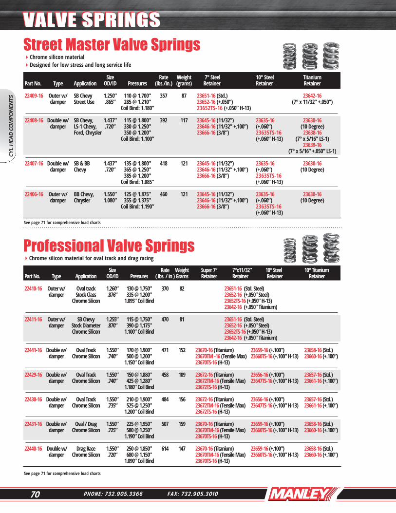
Street Master Valve SpringsChrome silicon material Designed for low stress and long service life
Professional Valve SpringsChrome silicon material for oval track and drag racing
Size Rate Weight 7° Steel 10° Steel Titanium Part No. Type Application OD/ID Pressures (lbs./in.) (grams) Retainer Retainer Retainer 22409-16 Outer w/ SB Chevy 1.250” 110 @ 1.700” 357 87 23651-16 (Std.) 23642-16 damper Street Use .865” 285 @ 1.210” 23652-16 (+.050”) (7° x 11/32” +.050”) Coil Bind: 1.180” 23652TS-16 (+.050” H-13) 22408-16 Double w/ SB Chevy, 1.437” 115 @ 1.800” 392 117 23645-16 (11/32”) 23635-16 23630-16 damper LS-1 Chevy, .720” 330 @ 1.250” 23646-16 (11/32” +.100”) (+.060”) (10 Degree) Ford, Chrysler 350 @ 1.200” 23666-16 (3/8”) 23635TS-16 23638-16 Coil Bind: 1.100” (+.060” H-13) (7° x 5/16” LS-1) 23639-16 (7° x 5/16” +.050” LS-1) 22407-16 Double w/ SB & BB 1.437” 135 @ 1.800” 418 121 23645-16 (11/32”) 23635-16 23630-16 damper Chevy .720” 365 @ 1.250” 23646-16 (11/32” +.100”) (+.060”) (10 Degree) 385 @ 1.200” 23666-16 (3/8”) 23635TS-16 Coil Bind: 1.085” (+.060” H-13) 22406-16 Outer w/ BB Chevy, 1.550” 125 @ 1.875” 460 121 23645-16 (11/32”) 23635-16 23630-16 damper Chrysler 1.080” 355 @ 1.375” 23646-16 (11/32” +.100”) (+.060”) (10 Degree) Coil Bind: 1.190” 23666-16 (3/8”) 23635TS-16 (+.060” H-13)
Size Rate Weight Super 7° 7°x11/32” 10° Steel 10° Titanium Part No. Type Application OD/ID Pressures ( lbs. / in ) Grams Retainer Retainer Retainer Retainer 22410-16 Outer w/ Oval track 1.260” 130 @ 1.750” 370 82 23651-16 (Std. Steel) damper Stock Class .876” 335 @ 1.200” 23652-16 (+.050” Steel) Chrome Silicon 1.095” Coil Bind 23652TS-16 (+.050” H-13) 23642-16 (+.050” Titanium) 22411-16 Outer w/ SB Chevy 1.255” 115 @ 1.750” 470 81 23651-16 (Std. Steel) damper Stock Diameter .870” 390 @ 1.175” 23652-16 (+.050” Steel) Chrome Silicon 1.100” Coil Bind 23652TS-16 (+.050” H-13) 23642-16 (+.050” Titanium) 22441-16 Double w/ Oval Track 1.550” 170 @ 1.900” 471 152 23670-16 (Titanium) 23659-16 (+.100”) 23658-16 (Std.) damper Chrome Silicon .740” 500 @ 1.200” 23670TM -16 (Tensile Max) 23660TS-16 (+.100” H-13) 23660-16 (+.100”) 1.150” Coil Bind 23670TS-16 (H-13) 22429-16 Double w/ Oval Track 1.550” 150 @ 1.880” 458 109 23672-16 (Titanium) 23656-16 (+.100”) 23657-16 (Std.) damper Chrome Silicon .740” 425 @ 1.280” 23672TM-16 (Tensile Max) 23647TS-16 (+.100” H-13) 23661-16 (+.100”) 1.180” Coil Bind 23672TS-16 (H-13) 22430-16 Double w/ Oval Track 1.550” 210 @ 1.900” 484 156 23672-16 (Titanium) 23656-16 (+.100”) 23657-16 (Std.) damper Chrome Silicon .735” 525 @ 1.250” 23672TM-16 (Tensile Max) 23647TS-16 (+.100” H-13) 23661-16 (+.100”) 1.200” Coil Bind 23672TS-16 (H-13)
22431-16 Double w/ Oval / Drag 1.550” 225 @ 1.950” 507 159 23670-16 (Titanium) 23659-16 (+.100”) 23658-16 (Std.) damper Chrome Silicon .725” 580 @ 1.250” 23670TM-16 (Tensile Max) 23660TS-16 (+.100” H-13) 23660-16 (+.100”) 1.190” Coil Bind 23670TS-16 (H-13) 22440-16 Double w/ Drag Race 1.550” 250 @ 1.850” 614 147 23670-16 (Titanium) 23659-16 (+.100”) 23658-16 (Std.) damper Chrome Silicon .720” 680 @ 1.150” 23670TM-16 (Tensile Max) 23660TS-16 (+.100” H-13) 23660-16 (+.100”) 1.090” Coil Bind 23670TS-16 (H-13)
See page 71 for comprehensive load charts
See page 71 for comprehensive load charts
CYL
HEA
D C
OM
PON
ENTS
VALVE SPRINGSVALVE SPRINGS
71W W W . M A N L E Y P E R F O R M A N C E . C O M
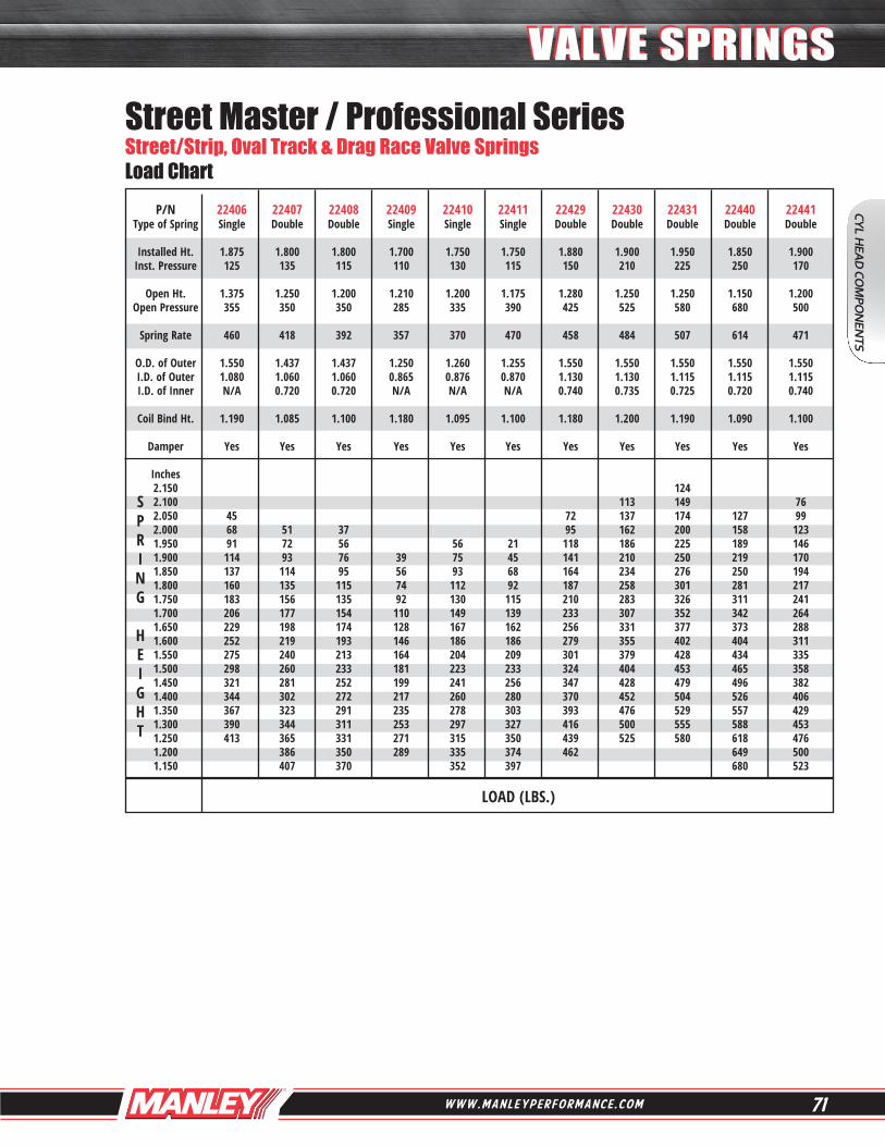
Street Master / Professional Series Street/Strip, Oval Track & Drag Race Valve Springs Load Chart P/N 22406 22407 22408 22409 22410 22411 22429 22430 22431 22440 22441 Type of Spring Single Double Double Single Single Single Double Double Double Double Double Installed Ht. 1.875 1.800 1.800 1.700 1.750 1.750 1.880 1.900 1.950 1.850 1.900 Inst. Pressure 125 135 115 110 130 115 150 210 225 250 170 Open Ht. 1.375 1.250 1.200 1.210 1.200 1.175 1.280 1.250 1.250 1.150 1.200 Open Pressure 355 350 350 285 335 390 425 525 580 680 500 Spring Rate 460 418 392 357 370 470 458 484 507 614 471 O.D. of Outer 1.550 1.437 1.437 1.250 1.260 1.255 1.550 1.550 1.550 1.550 1.550 I.D. of Outer 1.080 1.060 1.060 0.865 0.876 0.870 1.130 1.130 1.115 1.115 1.115 I.D. of Inner N/A 0.720 0.720 N/A N/A N/A 0.740 0.735 0.725 0.720 0.740 Coil Bind Ht. 1.190 1.085 1.100 1.180 1.095 1.100 1.180 1.200 1.190 1.090 1.100 Damper Yes Yes Yes Yes Yes Yes Yes Yes Yes Yes Yes
Inches 2.150 124
2.100 113 149 76 2.050 45 72 137 174 127 99 2.000 68 51 37 95 162 200 158 123 1.950 91 72 56 56 21 118 186 225 189 146 1.900 114 93 76 39 75 45 141 210 250 219 170 1.850 137 114 95 56 93 68 164 234 276 250 194 1.800 160 135 115 74 112 92 187 258 301 281 217 1.750 183 156 135 92 130 115 210 283 326 311 241 1.700 206 177 154 110 149 139 233 307 352 342 264 1.650 229 198 174 128 167 162 256 331 377 373 288 1.600 252 219 193 146 186 186 279 355 402 404 311 1.550 275 240 213 164 204 209 301 379 428 434 335 1.500 298 260 233 181 223 233 324 404 453 465 358 1.450 321 281 252 199 241 256 347 428 479 496 382 1.400 344 302 272 217 260 280 370 452 504 526 406 1.350 367 323 291 235 278 303 393 476 529 557 429 1.300 390 344 311 253 297 327 416 500 555 588 453 1.250 413 365 331 271 315 350 439 525 580 618 476 1.200 386 350 289 335 374 462 649 500
1.150 407 370 352 397 680 523
S P R I N G H E I G H T
LOAD (LBS.)
CYL HEA
D CO
MPO
NEN
TS
VALVE SPRINGSVALVE SPRINGS

72 P H O N E : 7 3 2 . 9 0 5 . 3 3 6 6 F A X : 7 3 2 . 9 0 5 . 3 0 1 0
NexTek® Series Drag Race, Oval Track & Endurance Valve Springs Load Chart
Note: BOLD loads correspond to installed and open pressures.
S P R I N G H E I G H T
P/N 221420 221424/P 221425/P 221432 221440P 221441P 221442 221443/P 221444/P 221445P 221446SF Type of Spring Double Double Double Double Double Double Double Double Double Double Double Color Code Super Blue/ Green/ Silver Polished Polished Polished White/ Yellow/ Polished Super Finished Polished Polished Polished Polished Finished Installed Ht. 2.050 2.000 2.100 1.900 2.000 2.030 2.000 1.950 2.050 2.050 2.050 Inst. Pressure 275 250 280 150 255 280 260 235 235 280 240 Open Ht. 1.200 1.150 1.250 1.270 1.300 1.300 1.250 1.250 1.300 1.250 1.250 Open Pressure 940 800 795 425 630 700 660 610 645 680 700 Spring Rate 780 647 604 435 534 575 533 535 546 500 575 O.D. of Outer 1.500 1.640 1.640 1.530 1.570 1.570 1.560 1.580 1.610 1.620 1.400 I.D. of Outer 1.050 1.185 1.185 1.141 1.137 1.121 1.127 1.147 1.161 1.187 0.990 I.D. of Inner 0.710 0.860 0.860 0.750 0.760 0.750 0.812 0.832 0.842 0.852 0.700 Coil Bind Ht. 1.130 1.070 1.150 1.170 1.190 1.215 1.200 1.170 1.220 1.200 1.150 Damper No No No Yes Yes Yes No No No No No
Inches 2.350 41 2.300 80 159 2.250 119 189 126 180 125 2.200 158 121 220 148 182 153 153 205 154 2.150 197 153 250 175 211 180 128 180 230 183 2.100 236 185 280 63 202 240 207 155 208 255 211 2.050 275 218 310 85 228 268 233 182 235 280 240 2.000 314 250 340 107 255 297 260 208 262 305 269 1.950 353 282 371 128 282 326 287 235 290 330 298 1.900 392 315 401 150 308 355 313 262 317 355 326 1.850 431 347 431 172 335 383 340 289 344 380 355 1.800 470 379 461 194 362 412 367 315 372 405 384 1.750 509 412 491 215 389 441 393 342 399 430 413 1.700 548 444 522 237 415 470 420 369 426 455 441 1.650 587 476 552 259 442 498 447 396 453 480 470 1.600 626 509 582 281 469 527 473 422 481 505 499 1.550 665 541 612 302 495 556 500 449 508 530 528 1.500 704 574 642 324 522 585 527 476 535 555 556 1.450 743 606 673 346 549 613 553 503 563 580 585 1.400 782 638 703 368 575 642 580 529 590 605 614 1.350 821 671 733 389 602 671 606 556 617 630 643 1.300 860 703 763 411 630 700 633 583 645 655 671 1.250 899 735 795 433 656 728 660 610 672 680 700 1.200 940 768 824 455 636 729 1.150 977 800 1.100 832
LOAD (LBS.)
CYL
HEA
D C
OM
PON
ENTS
VALVE SPRINGSVALVE SPRINGS

73W W W . M A N L E Y P E R F O R M A N C E . C O M
Note: BOLD loads correspond to installed and open pressures.
NexTek® Series Drag Race, Oval Track & Endurance Valve Springs Load Chart P/N 221447/P 221448/P 221449/P 221450/P 221452SF 221454/P 221455 221456 221457 221460 221461 Type of Spring Triple Triple Triple Triple Double Double Double Double Double Double Double Color Code Pink/ Orange/ Red/ Purple/ Super Orange/ Super Super Super Super Super Polished Polished Polished Polished Finished Polished Finished Finished Finished Finished Finished Installed Ht. 2.000 2.100 2.200 2.200 2.025 2.000 2.175 2.100 2.150 2.250 2.300 Inst. Pressure 350 350 350 370 250 290 450 330 405 440 425 Open Ht. 1.270 1.200 1.200 1.200 1.200 1.150 1.175 1.200 1.200 1.300 1.300 Open Pressure 895 1010 1070 1140 750 825 1250 1050 1165 1340 1389 Spring Rate 746 733 720 770 618 635 797 800 800 948 964 O.D. of Outer 1.677 1.677 1.677 1.677 1.550 1.650 1.500 1.500 1.500 1.522 1.540 I.D. of Outer 1.203 1.203 1.203 1.203 1.130 1.185 1.050 1.050 1.050 1.050 1.050 I.D. of Middle 0.874 0.874 0.874 0.874 N/A N/A N/A N/A N/A N/A N/A I.D. of Inner 0.635 0.635 0.632 0.632 0.800 0.860 0.710 0.710 0.710 0.710 0.710 Coil Bind Ht. 1.160 1.142 1.142 1.142 1.150 1.105 1.130 1.130 1.130 1.255 1.215 Damper No No No No No No No No No No No
Inches 2.500 233 2.450 250 281 2.400 206 216 298 329
2.350 242 255 311 245 345 377 2.300 203 278 293 350 170 285 393 425 2.250 240 314 332 111 390 210 325 440 473 2.200 201 277 350 370 142 161 430 250 365 487 521 2.150 238 313 386 409 173 193 470 290 405 535 570 2.100 275 350 422 447 204 225 510 330 445 582 618 2.050 313 387 458 486 235 256 550 370 485 630 666 2.000 350 423 494 524 266 290 590 410 525 677 714 1.950 387 460 530 563 297 320 629 450 565 724 762 1.900 425 497 566 601 328 352 669 490 605 772 811 1.850 462 533 602 640 359 383 709 530 645 819 859 1.800 499 570 638 678 390 415 749 570 685 867 907 1.750 537 607 674 717 420 447 789 610 725 914 955 1.700 574 643 710 755 451 479 829 650 765 961 1003 1.650 611 680 746 794 482 510 869 690 805 1009 1052 1.600 648 717 782 832 513 542 908 730 845 1056 1100 1.550 686 753 818 871 544 574 948 770 885 1104 1148 1.500 723 790 854 909 575 606 988 810 925 1151 1196 1.450 760 826 890 948 606 637 1028 850 965 1198 1244 1.400 798 863 926 986 637 669 1068 890 1005 1246 1293
1.350 835 900 962 1025 668 701 1108 930 1045 1293 1341 1.300 872 936 998 1063 699 733 1147 970 1085 1340 1389 1.250 910 973 1034 1102 719 764 1187 1010 1125 1437 1.200 947 1010 1070 1140 750 796 1227 1050 1165 1.150 828 1267 1090 1205
S P R I N G H E I G H T
LOAD (LBS.)
CYL HEA
D CO
MPO
NEN
TS
VALVE SPRINGSVALVE SPRINGS
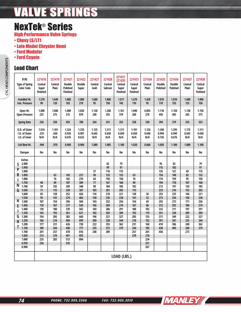
74 P H O N E : 7 3 2 . 9 0 5 . 3 3 6 6 F A X : 7 3 2 . 9 0 5 . 3 0 1 0
221431221439
S P R I N G H E I G H T
LOAD (LBS.)
NexTek® Series High Performance Valve Springs• Chevy LS/LT1• Late Model Chrysler Hemi• Ford Modular • Ford Coyote Load Chart P/N 221418 221419 221421 221422 221427 221428 221433 221434 221435 221436 221437 221438 Type of Spring Conical Conical Double Double Conical Conical Conical Conical Conical Double Double Conical Conical Color Code Super Plain Polished Super Gold Salmon Super Super Plain Polished Polished Plain Super Finished Finished Finished Finished Finished Installed Ht. 1.570 1.640 1.800 1.800 1.680 1.800 1.811 1.670 1.420 1.810 1.810 1.680 1.800 Inst. Pressure 90 120 165 270 95 150 145 110 95 170 155 125 150 Open Ht. 1.000 1.040 1.000 1.020 1.130 1.200 1.161 1.090 0.895 1.110 1.150 1.130 1.150 Open Pressure 225 275 515 870 240 355 370 260 270 450 405 265 375 Spring Rate 236 258 435 780 264 341 353 258 330 394 379 255 353 O.D. of Outer 1.014 1.101 1.324 1.335 1.125 1.311 1.311 1.101 1.126 1.340 1.295 1.175 1.311 I.D. of Outer .533 .650 0.920 0.907 0.642 0.650 0.650 0.650 0.640 0.994 0.949 0.642 0.650 I.D. of Inner N/A N/A 0.676 0.622 N/A N/A N/A N/A N/A 0.726 0.676 N/A N/A Coil Bind Ht. .904 .970 0.900 0.960 1.080 1.085 1.100 1.020 0.860 1.050 1.100 1.080 1.100 Damper No No No No No No No No No No No No No
Inches 2.000 82 79 95 83 79 1.950 99 97 115 102 97 1.900 37 116 115 135 121 69 115 1.850 63 143 231 50 133 132 63 154 140 82 132 1.800 76 165 270 64 150 150 76 174 159 95 150 1.750 48 89 187 309 77 167 168 89 194 178 107 168 1.700 59 102 209 348 90 184 185 102 213 197 120 185 1.650 71 115 230 387 103 201 203 115 233 216 133 203 1.600 83 128 252 426 116 218 221 128 36 253 235 146 221 1.550 95 141 274 465 130 235 238 141 53 273 254 158 238 1.500 107 154 296 504 143 252 256 154 69 292 273 171 256 1.450 118 167 317 543 156 269 274 167 86 312 292 184 274 1.400 130 180 339 582 169 286 291 180 102 332 311 197 291 1.350 142 192 361 621 182 303 309 192 119 351 330 209 309 1.300 154 205 383 660 196 321 327 205 135 371 349 222 327 1.250 166 218 404 699 209 338 344 218 152 391 367 235 344 1.200 177 231 426 738 222 355 362 231 168 410 386 248 362 1.150 189 244 448 777 235 372 379 244 185 430 405 260 379 1.100 201 257 470 816 248 389 257 201 450 273 1.050 213 270 491 855 270 218 1.000 225 283 513 894 234 0.950 236 535 251 0.900 267
CYL
HEA
D C
OM
PON
ENTS
VALVE SPRINGSVALVE SPRINGS
75W W W . M A N L E Y P E R F O R M A N C E . C O M
CYL HEA
D CO
MPO
NEN
TS
SPRING RETAINERSSPRING RETAINERS
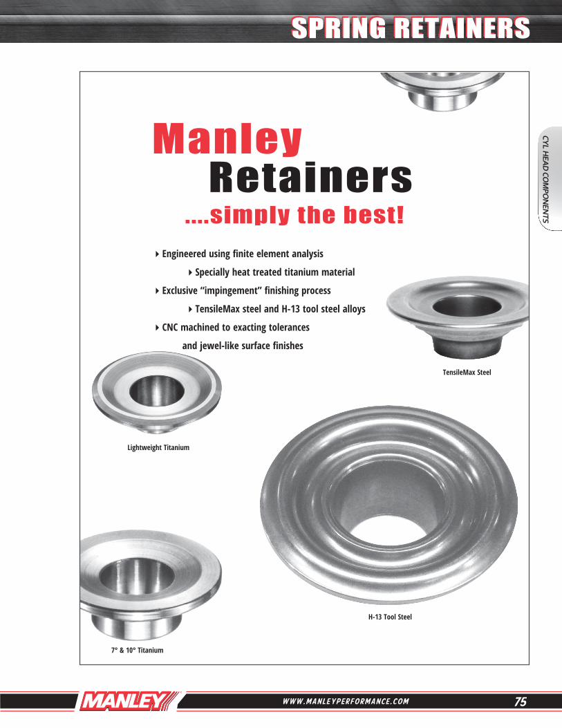
Manley Retainers ....simply the best!Engineered using finite element analysis
Specially heat treated titanium material
Exclusive “impingement” finishing process
TensileMax steel and H-13 tool steel alloys
CNC machined to exacting tolerances
and jewel-like surface finishes
7° & 10° Titanium
TensileMax Steel
Lightweight Titanium
H-13 Tool Steel

76 P H O N E : 7 3 2 . 9 0 5 . 3 3 6 6 F A X : 7 3 2 . 9 0 5 . 3 0 1 0
CYL
HEA
D C
OM
PON
ENTS
SPRING RETAINERSSPRING RETAINERS
BULK PRICING AVAILABLE
Super 7° Titanium Retainers
Please call with your custom retainer requirements
Super 7° angle is actually 8° Heat treated titanium material for maximum strength Available with or without our exclusive impingement surface enhancement process Impingement results in a 20% improvement in resistance to abrasion, a 30% improvement in fatigue strength, and an overall improvement in surface finish“L” Suffix indicates Lightweight version which is 3-4 grams lighter than standard part number
Ti-17 ALLOY
Part No. w/ Spring Spring Dimensions Wgt/ Part No. Impinge Quantity Type Spring O.D. A B C D Grams
23746L-16 - - - - - - - - 16 pcs. Double Manley 221446SF 1.400” 1.260” 0.980” .690” --- 12
23701-16 - - - - - - - - 16 pcs. Double Manley 221420, 1455, 1.500” 1.325” 1.035” .705” --- 14 1456, 1457, 1460, 1461 23700L-16 23700LI-16 16 pcs. Double PSI CT1040 1.500” 1.450” 1.080” .785” --- 16 23707-16 - - - - - - - - 16 pcs. Double Manley 221432 1.530” / 1.575” 1.500” 1.125” .740” --- 20 23670-16 - - - - - - - - 16 pcs. Double Manley 22431, 22440, 22441 1.550” 1.500” 1.105” .710” --- 19 23702L-16 - - - - - - - - 16 pcs. Double Manley 221452SF 1.550” 1.450” 1.120” .790” --- 17 23672-16 23672I-16 16 pcs. Double Manley 221441P, 22429, 22430 1.550” 1.500” 1.125” .730” --- 18 23672L-16 - - - - - - - - 16 pcs. Double 20% lighter than 23672 1.550” 1.450” 1.125” .730” --- 14
23674L-16 23674LI-16 16 pcs. Double Comp. 927 1.550” 1.450” 1.140” .730” --- 17
23669-16 - - - - - - - - 16 pcs. Double Comp 26099 1.550”/1.625” 1.500” 1.175” .765” --- 21 23705L-16 23705LI-16 16 pcs. Double Manley 221440P 1.560” 1.450” 1.140” .745” --- 16 23706L-16 23706LI-16 16 pcs. Double .050” more installed 1.560” 1.450” 1.140” .745” --- 16 than 23705L
23682-16 - - - - - - - - 16 pcs. Double Manley 221442 1.560” 1.500” 1.120” .805” --- 21 23682L-16 - - - - - - - - 16 pcs. Double 16% lighter than 23682 1.560” 1.450” 1.120” .805” --- 17
23681-16 - - - - - - - - 16 pcs. Double Manley 221443, 221444 1.580” / 1.610” 1.500” 1.150” .825” --- 21 23681L-16 23681LI-16 16 pcs. Double 17% lighter than 23681 1.580” / 1.610” 1.450” 1.150” .825” --- 18 23691-16 - - - - - - - - 16 pcs. Double .050” more installed 1.580” / 1.610” 1.500” 1.150” .825” --- 20 than 23681 23685-16 23685I-16 16 pcs. Double Manley 221445P 1.620” 1.500” 1.175” .840” --- 20 23685L-16 23685LI-16 16 pcs. Double 16% lighter than 23685 1.620” 1.460” 1.175” .840” --- 17
23708L-16 - - - - - - - - 16 pcs. Triple Manley 221447, 221448 1.660” 1.450” 1.185” .870” .635” 17 221449, 221450

77W W W . M A N L E Y P E R F O R M A N C E . C O M
CYL HEA
D CO
MPO
NEN
TS
SPRING RETAINERSSPRING RETAINERS
Special 6AL-4V titanium for maximum strength
Excellent value for all forms of racing
See page 78 for Lightweight 10° Titanium Retainers
10° Titanium RetainersBULK PRICING
AVAILABLE
Spring Spring Dimensions Wgt/ Part No. Quantity Type Spring Height O.D. A B C D Grams 23630-16 16 pcs. Outer-Inner 22406, 22407, 22408 Std. 1.437”/1.550” 1.440” 1.050” .700” --- 15 ...... 23684-16 16 pcs. Double Manley 221420, 1455, Std. 1.500” 1.325” 1.035” .705” --- 14 1456, 1457, 1460, 1461
23644-16 16 pcs. Double Manley 221432, Std. 1.550” 1.500” 1.140” .740” --- 17 Manley 221440P, Comp. 927 23658-16 16 pcs. Double Manley 22431, 22440, 22441 Std. 1.550” 1.500” 1.105” .710” --- 16 23657-16 16 pcs. Double Manley 22429, 22430 Std. 1.550” 1.500” 1.120” .705” --- 18 23649-16 16 pcs. Double Manley 221424, 221425, 221454 Std. 1.625” 1.500” 1.175” .850” --- 19 23654-16 16 pcs. Double Comp. 26099 Std. 1.625” 1.500” 1.175” .765” --- 17
23663-16 16 pcs. Triple Manley 221447, 221448, Std. 1.660” 1.500” 1.185” .860” .620” 21 221449, 221450
23619-16 16 pcs. Double Manley 221422 +.050” 1.335” 1.235” .900” .615” --- 11 23676-16 16 pcs. Double Manley 221420, 1455, +.100” 1.500” 1.325” 1.035” .705” --- 13 1456, 1457, 1460, 1461 23641-16 16 pcs. Triple Crane 99882 +.100” 1.550” 1.500” 1.130” .735” .640” 17 23650-16 16 pcs. Double Manley 221432, +.100” 1.530”/1.570” 1.500” 1.140” .740” --- 18 Manley 221440P, Comp. 927 23660-16 16 pcs. Double Manley 22431, 22440, 22441 +.100” 1.550” 1.500” 1.105” .710” --- 17 23661-16 16 pcs. Double Manley 22429, 22430 +.100” 1.550” 1.500” 1.120” .705” --- 17 23647-16 16 pcs. Double Manley 221441P, Comp. 938, K-950 +.100” 1.550” 1.500” 1.120” .730” --- 18 23643-16 16 pcs. Double Manley 221442 +.100” 1.560” 1.500” 1.120” .805” --- 19 23648-16 16 pcs. Double Manley 221443, 221444 +.100” 1.580”/1.610” 1.500” 1.150” .825” --- 20 Comp. 951 00 23655-16 16 pcs. Double Comp. 26099 +.100” 1.625” 1.500” 1.175” .750” --- 17 23640-16 16 pcs. Double Manley 221424, 221425, 221454 +.100” 1.625” 1.500” 1.175” .850” --- 20 23662-16 16 pcs. Triple Comp. 948 +.100” 1.625” 1.500” 1.190” .875” .640” 19 23665-16 16 pcs. Triple K-1400 +.100” 1.625” 1.500” 1.185” .765” .645” 18 23653-16 16 pcs. Triple Manley 221447, 221448, +.100” 1.660” 1.500” 1.185” .860” .620” 19 221449, 221450

78 P H O N E : 7 3 2 . 9 0 5 . 3 3 6 6 F A X : 7 3 2 . 9 0 5 . 3 0 1 0
CYL
HEA
D C
OM
PON
ENTS
SPRING RETAINERSSPRING RETAINERSLightweight 10° Titanium RetainersSqueeze more RPM’s out of your engine Avoid valve float Lightweight retainer does not sacrifice reliability 16 grams - compared to normal 19 to 21 grams Special heat treated titanium for maximum strength Must use 10° valve locks
BULK PRICING AVAILABLE
Spring Spring Dimensions Wgt/ Part No. Quantity Type Spring Height O.D. A B C D Grams 23540-16 16 pcs. Double Manley 221424, 221425, 221454 +.100” 1.625” 1.430” 1.175” .850” - - - 17 23562-16 16 pcs. Triple Pacaloy +.100” 1.625” / 1.430” 1.190” .875” .640” 16 Comp 946, 947, 948 1.650” 23553-16 16 pcs. Triple Manley 221447, 221448, +.100” 1.660” 1.430” 1.185” .860” .620” 16 221449, 221450 23553I-16 16 pcs. Triple Manley 221447, 221448, +.100” 1.660” 1.430” 1.185” .860” .620” 16 221449, 221450 23553 I retainer is impinged. 23679-16* 16 pcs. Double Manley 221420, 1455, +.100” 1.500” 1.325” 1.035” .705” - - - 14 1456, 1457, 1460, 1461 23683-16* 16 pcs. Double Manley 221420, 1455, +.170” 1.500” 1.325” 1.035” .705” - - - 14 1456, 1457, 1460, 1461 23753-16* 16 pcs. Triple Manley 221447, 221448, +.100” 1.660” 1.430” 1.185” .860” .620” 17 221449, 221450 * Made from our high strength TI-17 Titanium Material
ATI Racing

79W W W . M A N L E Y P E R F O R M A N C E . C O M
CYL HEA
D CO
MPO
NEN
TS
SPRING RETAINERSSPRING RETAINERS
x
7° Titanium RetainersSpecial 6AL-4V titanium for maximum strengthCAD designed for ultimate reduction in mass without sacrificing strengthMust use 7° valve locks
P/N’s 23624, 23626, and 23642 are for the following engine models: LT-1 / LT-4 / L-98 and must use Manley P/N 13091
P/N’s 23611, 23617, 23618, 23622, 23623, 23625, 23638, and 23639 must use Manley P/N 13098 or factory Chevrolet LS valve locks
* Made from our high strength TI-17 Titanium Material
Spring Dimensions Keeper Valve Wgt/ Part No. Quantity Spring Height O.D. A B C Degree Stem Grams 23614-24 24 pcs. Manley 221433 Std. 1.013” .875” .640” .440” 7° x 6mm 5 23605-32 32 pcs. Manley 221419 +.070” 1.013” .875” .640” .440” 7° x 6mm 5 23627-16 16 pcs. Manley 221427/221437 Std. 1.020”/1.030” .875” .627” .465” 7° x 7mm 5 23667-16 16 pcs. Manley 221427/221437 +.060” 1.020”/1.030” .875” .627” .465” 7° x 7mm 5 23629-16 16 pcs. PSI 1511ML Std. 1.056” .915” .620” .540” 7° x 5/16” 5
23613-16 16 pcs. Manley 221431, 221439 Std. 1.076” .935” .640” .570” 7° x 5/16” 6 23622-16 16 pcs. Manley 221428/221438 Std. 1.076” .935” .640” .570” 7° x 8mm 5 23625-16 16 pcs. Manley 221428/221438 +.050” 1.076” .935” .640” .570” 7° x 8mm 5 23626-16 16 pcs. Manley 221428/221438 +.050” 1.076” .935” .640” .575” 7° x 11/32” 6 23642-16 16 pcs. Manley 22409, 22410, 22411 +.050” 1.250” 1.150” .865” .620” 7° x 11/32” 9
23617-16 16 pcs. Manley 221436 Std. 1.295” 1.155” .950” .675” 7° x 8mm 10 23623-16 16 pcs. Manley 221436 +.050” 1.295” 1.155” .950” .675” 7° x 8mm 10 23624-16 16 pcs. Manley 221436 +.050” 1.295” 1.155” .950” .675” 7° x 11/32” 10 23618-16 16 pcs. Manley 221421 +.050” 1.324” 1.200” .910” .666” 7° x 8mm 11 23611-16 16 pcs. Manley 221435 +.050” 1.340” 1.200” .985” .715” 7° x 8mm 11
23638-16 16 pcs. Manley 22408 Std. 1.437” 1.340” 1.050” .700” 7° x 8mm 14 23639-16 16 pcs. Manley 22408 +.050” 1.437” 1.340” 1.050” .700” 7° x 8mm 14 23675-16 16 pcs. Manley 221420, 1455, +.100” 1.500” 1.325” 1.035” .705” 7° x 11/32”, 3/8” 14 1456, 1457, 1460, 1461 23677-16* 16 pcs. Manley 221420, 1455, +.100” 1.500” 1.325” 1.035” .705” 7° x 11/32”, 3/8” 15 1456, 1457, 1460, 1461 23673-16 16 pcs. Manley 221447, 221448, +.100” 1.660” 1.500” 1.185” .860” 7° x 11/32”, 3/8” 20 221449, 221450

Spring Spring Keeper Dimensions Wgt/ Part No. Quantity Type Spring O.D. Degree A B C Grams 23746TM-16 16 pcs. Double Manley 221446SF 1.400” Super 7° 1.260” 0.980” .690” 16 23675TM-16 16 pcs. Double Manley 221420, 1455, 1.500” 7° (+.100”) 1.325” 01.035” .705” 18 1456, 1457, 1460, 1461 23676TM-16 16 pcs. Double Manley 221420, 1455, 1.500” 10° (+.100”) 1.325” 01.035” .705” 17 1456, 1457, 1460, 1461
23707TM-16 16 pcs. Double Manley 221432 1.530” Super 7° 1.420” 1.125” .740” 21 23670TM-16 16 pcs. Double Manley 22431, 22440, 22441 1.550” Super 7° 1.420” 1.105” .710” 20
23702LTM-16 16 pcs. Double Manley 221452SF 1.550” Super 7° 1.440” 1.120” .790” 20
23674TM-16 16 pcs. Double Comp. 927 1.550” Super 7° 1.440” 1.140” .730” 22 23682TM-16 16 pcs. Double Manley 221442 1.560” Super 7° 1.440” 1.120” .805” 23 23672TM-16 16 pcs. Double Manley 221441P, 22429, 22430 1.570” Super 7° 1.440” 1.125” .730” 20 23705TM-16 16 pcs. Double Manley 221440P 1.570 “ Super 7° 1.440” 1.140” .745” 22 23705LTM-16 16 pcs. Double 14% lighter than 23705TM 1.570 “ Super 7° 1.440” 1.140” .745” 19 23685TM-16 16 pcs. Double Manley 221445P 1.620” Super 7° 1.460” 1.175” .840” 23
80 P H O N E : 7 3 2 . 9 0 5 . 3 3 6 6 F A X : 7 3 2 . 9 0 5 . 3 0 1 0
CYL
HEA
D C
OM
PON
ENTS
SPRING RETAINERSSPRING RETAINERSTensileMax Steel RetainersManufactured from our incredibly tough TensileMax alloy Designed to be as light as standard titanium retainers and very close in weight to lightweight titanium versions (within 2-4 grams) Specially heat treated to provide a hardness of Rc 52-54 and prevent retainer wear Exclusive process yields a part that provides the optimum balance between ultimate strength, fatigue strength, hardness and ductility Unique impingement process developed specifically for our TensileMax alloy and hardness range to improve fatigue strength and promote better oiling between the spring and retainer
These are serious retainers for serious engine builders who DEMAND THE VERY BEST...
CNC Retainer Machining

For those searching for a slightly more economical alternative to titanium retainers, either to help solve a “wear problem” or because of “class rules,” Manley lightweight H-13 Tool Steel retainers are your solution! H-13 tool steel allows for better processing than “other” tool steels typically utilized; thus yielding a stronger, more durable product.
81W W W . M A N L E Y P E R F O R M A N C E . C O M
Lightweight H-13 Tool Steel Retainers
Up to 33% lighter than standard 10° steel retainersOnly 2-4 grams heavier than titanium versions Heat treated to provide a hardness of Rc 56
Call your Manley salesman to inquire about custom H-13 tool steel retainers
Spring Spring Keeper Dimensions Wgt/ Part No. Quantity Type Spring O.D. Degree A B C Grams 23605TS-32 32 pcs. Single Manley 221419 1.013” 7° x 6mm .875” .640” .440” 8 23606TS-16 16 pcs. Single Manley 221428, 221438 1.076” 10° (Std.) .935” .640” ----- 8 23652TS-16 16 pcs. Single Manley 22409, 22410, 22411 1.255” 7° x 11/32” (+.050”) 1.120” .865” .538” 13 23616TS-16 16 pcs. Double Manley 221436 1.290” 10° (+.050”) 1.155” .950” .675” 15 23615TS-16 16 pcs. Double Manley 221435 1.340” 10° (Std.) 1.190” .985” .715” 16 23746TS-16 16 pcs. Double Manley 221446SF 1.400” Super 7° 1.245” .980” .690” 17 23747TS-16 16 pcs. Double Manley 221446SF 1.400” 10° (+.100”) 1.245” .980” .690” 18
23635TS-16 16 pcs. Single/Double Manley 22406, 22407, 22408 1.437”/1.550” 10° (+.060”) 1.420” 1.050” .700” 20 23650TS-16 16 pcs. Double Manley 221432, 221440P 1.530”/1.570” 10° (+.100”) 1.440” 1.140” .740” 23
23660TS-16 16 pcs. Double Manley 22431, 22440, 22441 1.550” 10° (+.100”) 1.440” 1.105” .710” 21 23670TS-16 16 pcs. Double Manley 22431, 22440, 22441 1.550” Super 7° 1.440” 1.105” .710” 22 23702TS-16 16 pcs. Double Manley 221452SF 1.550” Super 7° 1.440” 1.120” .790” 23 23643TS-16 16 pcs. Double Manley 221442 1.560” 10° (+.100”) 1.440” 1.120” .805” 23 23682TS-16 16 pcs. Double Manley 221442 1.560” Super 7° 1.440” 1.120” .805” 23
23647TS-16 16 pcs. Double Manley 221441P, 22429, 22430 1.570” 10° (+.100”) 1.440” 1.120” .730” 22 23672TS-16 16 pcs. Double Manley 221441P, 22429, 22430 1.570” Super 7° 1.440” 1.125” .730” 20
23648TS-16 16 pcs. Double Manley 221443, 221444 1.580”/1.610” 10° (+.100”) 1.440” 1.150” .825” 24 23681TS-16 16 pcs. Double Manley 221443, 221444 1.580”/1.610” Super 7° 1.440” 1.150” .825” 24
CYL HEA
D CO
MPO
NEN
TS
SPRING RETAINERSSPRING RETAINERS
82 P H O N E : 7 3 2 . 9 0 5 . 3 3 6 6 F A X : 7 3 2 . 9 0 5 . 3 0 1 0
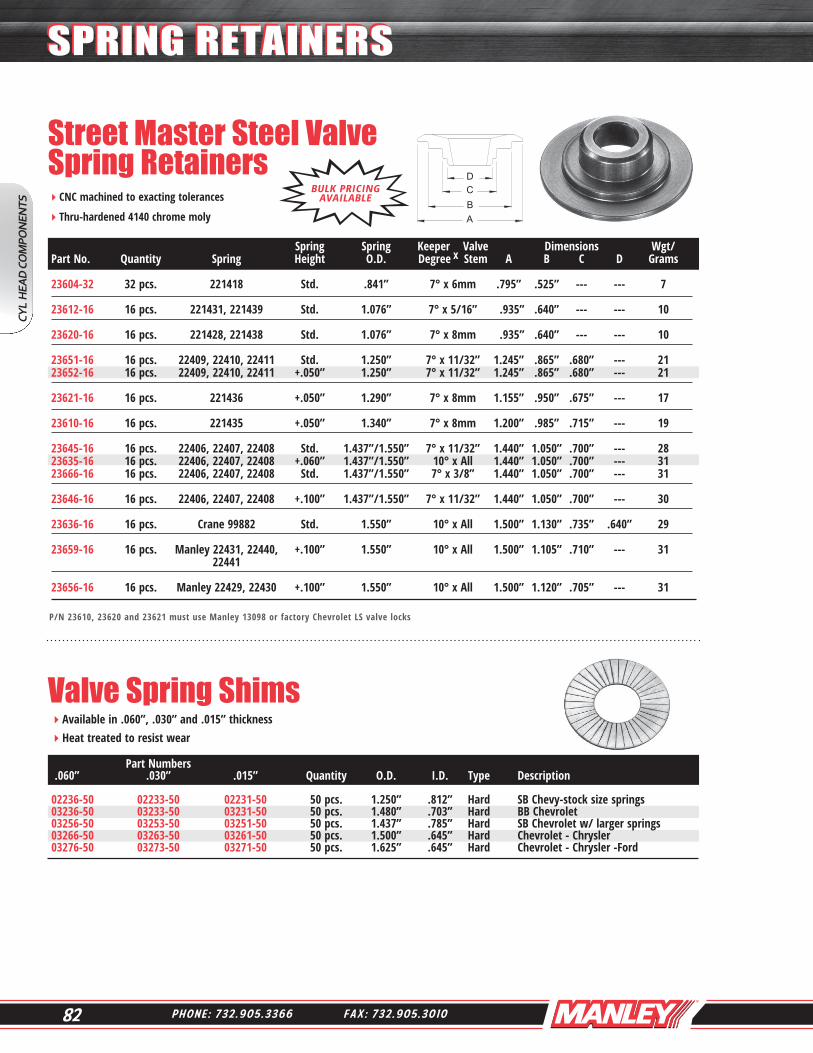
Street Master Steel Valve Spring RetainersCNC machined to exacting tolerances
Thru-hardened 4140 chrome moly
Valve Spring ShimsAvailable in .060”, .030” and .015” thickness Heat treated to resist wear
P/N 23610, 23620 and 23621 must use Manley 13098 or factory Chevrolet LS valve locks
x
BULK PRICING AVAILABLE
Part Numbers .060” .030” .015” Quantity O.D. I.D. Type Description 02236-50 02233-50 02231-50 50 pcs. 1.250” .812” Hard SB Chevy-stock size springs 03236-50 03233-50 03231-50 50 pcs. 1.480” .703” Hard BB Chevrolet 03256-50 03253-50 03251-50 50 pcs. 1.437” .785” Hard SB Chevrolet w/ larger springs 03266-50 03263-50 03261-50 50 pcs. 1.500” .645” Hard Chevrolet - Chrysler 03276-50 03273-50 03271-50 50 pcs. 1.625” .645” Hard Chevrolet - Chrysler -Ford
Spring Spring Keeper Valve Dimensions Wgt/ Part No. Quantity Spring Height O.D. Degree Stem A B C D Grams 23604-32 32 pcs. 221418 Std. .841” 7° x 6mm .795” .525” --- --- 7 23612-16 16 pcs. 221431, 221439 Std. 1.076” 7° x 5/16” .935” .640” --- --- 10 23620-16 16 pcs. 221428, 221438 Std. 1.076” 7° x 8mm .935” .640” --- --- 10 23651-16 16 pcs. 22409, 22410, 22411 Std. 1.250” 7° x 11/32” 1.245” .865” .680” --- 21 23652-16 16 pcs. 22409, 22410, 22411 +.050” 1.250” 7° x 11/32” 1.245” .865” .680” --- 21
23621-16 16 pcs. 221436 +.050” 1.290” 7° x 8mm 1.155” .950” .675” --- 17
23610-16 16 pcs. 221435 +.050” 1.340” 7° x 8mm 1.200” .985” .715” --- 19 23645-16 16 pcs. 22406, 22407, 22408 Std. 1.437”/1.550” 7° x 11/32” 1.440” 1.050” .700” --- 28 23635-16 16 pcs. 22406, 22407, 22408 +.060” 1.437”/1.550” 10° x All 1.440” 1.050” .700” --- 31 23666-16 16 pcs. 22406, 22407, 22408 Std. 1.437”/1.550” 7° x 3/8” 1.440” 1.050” .700” --- 31 23646-16 16 pcs. 22406, 22407, 22408 +.100” 1.437”/1.550” 7° x 11/32” 1.440” 1.050” .700” --- 30 23636-16 16 pcs. Crane 99882 Std. 1.550” 10° x All 1.500” 1.130” .735” .640” 29 23659-16 16 pcs. Manley 22431, 22440, +.100” 1.550” 10° x All 1.500” 1.105” .710” --- 31 22441 23656-16 16 pcs. Manley 22429, 22430 +.100” 1.550” 10° x All 1.500” 1.120” .705” --- 31
CYL
HEA
D C
OM
PON
ENTS
SPRING RETAINERSSPRING RETAINERS

83W W W . M A N L E Y P E R F O R M A N C E . C O M
O.D. Valve Spring CupsCNC machined
Accurate and durable .062” thick Heat treated and black oxide finished
Fits Spring Cup Cup Wall Shoulder Manley Use Cutter Part No. Quantity O.D. O.D. I.D. Height Spring Number 42142-16 16 pcs. 1.250” 1.390” .570” .150” 22409, 22410, 22411 41850 42126-16 16 pcs. 1.437” 1.550” .687” .150” 22407, 22408 41835 42122-16 16 pcs. 1.550” 1.680” .635” .150” 22429, 22430, 22431, 22440, 22441 41852 42377-16 16 pcs. 1.550” 1.680” .577” .150” 22429, 22430, 22431, 22440, 22441 41858 42370-16 16 pcs. 1.580” 1.687” .570” .140” 221443 41858 42365-16 16 pcs. 1.610” 1.740” .570” .140” 221444 41859 42121-16 16 pcs. 1.625” 1.740” .635” .150” 221424, 221425, 221454 41851 42128-16 16 pcs. 1.625” 1.740” .635” .250” 221424, 221425, 221454 41851 42379-16 16 pcs. 1.650” 1.740” .570” .250” 221424, 221425, 221454 41859 42371-16 16 pcs. 1.677” 1.740” .635” .140” 221447, 221448, 221449 41851 221450 42372-16 16 pcs. 1.677” 1.740” .570” .140” 221447, 221448, 221449 41859
Please call with your custom spring locator requirements
CNC machined to tolerances + .002” Excellent surface finish 8620 material heat treated and black oxide finished
Pro Series I.D. Valve Spring Locators
BULK PRICING AVAILABLE
BULK PRICING AVAILABLE
Fits Spring Locator Locator Locator Wall Shoulder Shoulder Manley Use Cutter Part No. Quantity O.D. O.D. I.D. Thickness Height Diameter Spring Number 42446-16 16 pcs. 1.400” 1.410” .567” .062” .163” .690” 221446SF 41850 42426-16 16 pcs. 1.550” 1.535” .567” .062” .163” .740” 221432, 221441P 41856 42466-16 16 pcs. 1.550” 1.535” .567” .045” .163” .740” 221432, 221441P 41856 42402-16 16 pcs. 1.550” 1.540” .567” .062” .163” .795” 221452SF 41856
42443-16 16 pcs. 1.560” 1.550” .567” .062” .163” .802” 221442 41856 42573-16 16 pcs. 1.580” 1.570” .567” .062” .163” .828” 221443 41856 42438-16 16 pcs. 1.580” 1.570” .567” .045” .163” .828” 221443 41856 42437-16 16 pcs. 1.625” 1.570” .567” .062” .163” .850” 221424, 221425, 221454 41857
CYL HEA
D CO
MPO
NEN
TS
SPRING CUPS & I.D. LOCATORSSPRING CUPS & I.D. LOCATORS
84 P H O N E : 7 3 2 . 9 0 5 . 3 3 6 6 F A X : 7 3 2 . 9 0 5 . 3 0 1 0
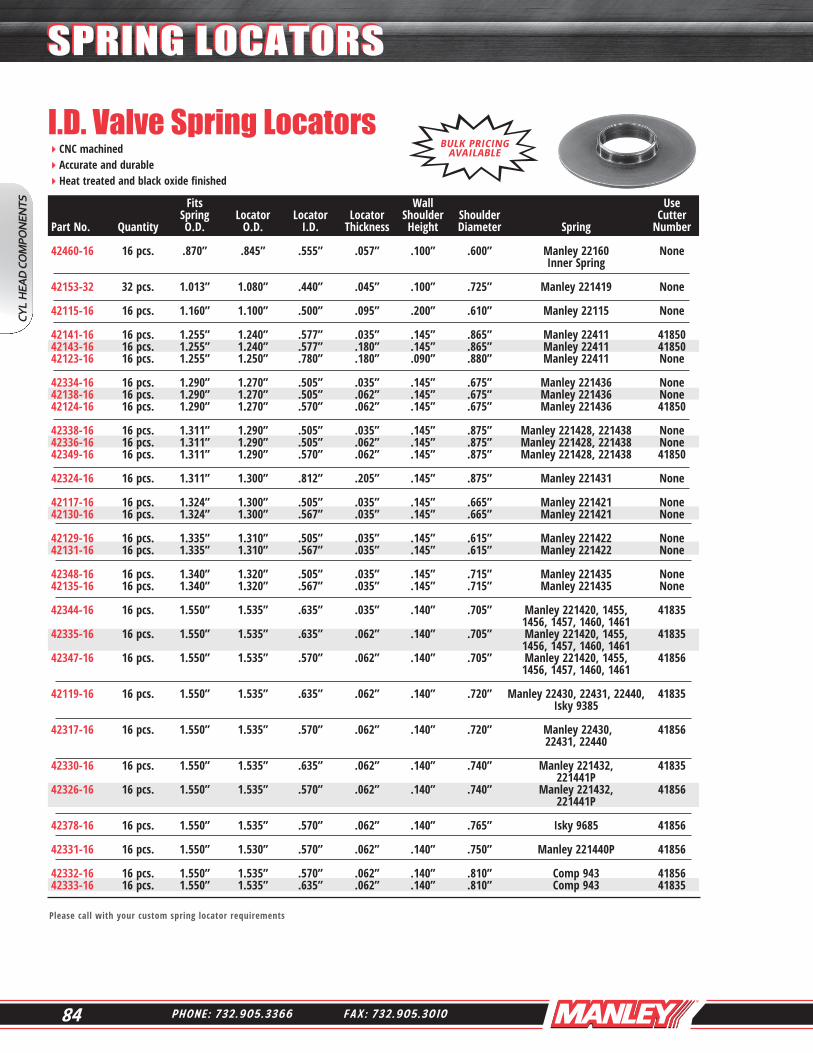
I.D. Valve Spring LocatorsCNC machinedAccurate and durableHeat treated and black oxide finished
Please call with your custom spring locator requirements
BULK PRICING AVAILABLE
Fits Wall Use Spring Locator Locator Locator Shoulder Shoulder Cutter Part No. Quantity O.D. O.D. I.D. Thickness Height Diameter Spring Number 42460-16 16 pcs. .870” .845” .555” .057” .100” .600” Manley 22160 None Inner Spring 42153-32 32 pcs. 1.013” 1.080” .440” .045” .100” .725” Manley 221419 None 42115-16 16 pcs. 1.160” 1.100” .500” .095” .200” .610” Manley 22115 None 42141-16 16 pcs. 1.255” 1.240” .577” .035” .145” .865” Manley 22411 41850 42143-16 16 pcs. 1.255” 1.240” .577” .180” .145” .865” Manley 22411 41850 42123-16 16 pcs. 1.255” 1.250” .780” .180” .090” .880” Manley 22411 None 42334-16 16 pcs. 1.290” 1.270” .505” .035” .145” .675” Manley 221436 None 42138-16 16 pcs. 1.290” 1.270” .505” .062” .145” .675” Manley 221436 None 42124-16 16 pcs. 1.290” 1.270” .570” .062” .145” .675” Manley 221436 41850
42338-16 16 pcs. 1.311” 1.290” .505” .035” .145” .875” Manley 221428, 221438 None 42336-16 16 pcs. 1.311” 1.290” .505” .062” .145” .875” Manley 221428, 221438 None 42349-16 16 pcs. 1.311” 1.290” .570” .062” .145” .875” Manley 221428, 221438 41850
42324-16 16 pcs. 1.311” 1.300” .812” .205” .145” .875” Manley 221431 None
42117-16 16 pcs. 1.324” 1.300” .505” .035” .145” .665” Manley 221421 None 42130-16 16 pcs. 1.324” 1.300” .567” .035” .145” .665” Manley 221421 None 42129-16 16 pcs. 1.335” 1.310” .505” .035” .145” .615” Manley 221422 None 42131-16 16 pcs. 1.335” 1.310” .567” .035” .145” .615” Manley 221422 None
42348-16 16 pcs. 1.340” 1.320” .505” .035” .145” .715” Manley 221435 None 42135-16 16 pcs. 1.340” 1.320” .567” .035” .145” .715” Manley 221435 None
42344-16 16 pcs. 1.550” 1.535” .635” .035” .140” .705” Manley 221420, 1455, 41835 1456, 1457, 1460, 1461 42335-16 16 pcs. 1.550” 1.535” .635” .062” .140” .705” Manley 221420, 1455, 41835 1456, 1457, 1460, 1461 42347-16 16 pcs. 1.550” 1.535” .570” .062” .140” .705” Manley 221420, 1455, 41856 1456, 1457, 1460, 1461 42119-16 16 pcs. 1.550” 1.535” .635” .062” .140” .720” Manley 22430, 22431, 22440, 41835 Isky 9385 42317-16 16 pcs. 1.550” 1.535” .570” .062” .140” .720” Manley 22430, 41856 22431, 22440 42330-16 16 pcs. 1.550” 1.535” .635” .062” .140” .740” Manley 221432, 41835 221441P 42326-16 16 pcs. 1.550” 1.535” .570” .062” .140” .740” Manley 221432, 41856 221441P 42378-16 16 pcs. 1.550” 1.535” .570” .062” .140” .765” Isky 9685 41856 42331-16 16 pcs. 1.550” 1.530” .570” .062” .140” .750” Manley 221440P 41856 42332-16 16 pcs. 1.550” 1.535” .570” .062” .140” .810” Comp 943 41856 42333-16 16 pcs. 1.550” 1.535” .635” .062” .140” .810” Comp 943 41835
CYL
HEA
D C
OM
PON
ENTS
SPRING LOCATORSSPRING LOCATORS

85W W W . M A N L E Y P E R F O R M A N C E . C O M
I.D. Valve Spring Locators (Continued)CNC machinedAccurate and durableHeat treated and black oxide finished
Please call with your custom spring locator requirements
Fits Wall Use Spring Locator Locator Cup Shoulder Shoulder Cutter Part No. Quantity O.D. O.D. I.D. Thickness Height Diameter Spring Number 42343-16 16 pcs. 1.560” 1.550” .567” .062” .163” .802” Manley 221442 41856 42373-16 16 pcs. 1.580” 1.570” .570” .062” .140” .825” Manley 221443 41856 42369-16 16 pcs. 1.580” 1.570” .635” .062” .140” .825” Manley 221443 41856 42367-16 16 pcs. 1.610” 1.610” .570” .062” .140” .825” Manley 221444 41857 42368-16 16 pcs. 1.610” 1.610” .635” .062” .140” .825” Manley 221444 41855 42342-16 16 pcs. 1.620” 1.610” .570” .062” .140” .840” Manley 221445P 41857 42337-16 16 pcs. 1.625” 1.570” .570” .062” .140” .850” Manley 221424, 221425, 221454 41857 42120-16 16 pcs. 1.625” 1.610” .635” .062” .140” .705” Manley 221420, 1455, 41855 1456, 1457, 1460, 1461 K Motion K1000, K1000H 42318-16 16 pcs. 1.625” 1.610” .570” .062” .140” .705” Manley 221420, 1455, 41857 1456, 1457, 1460, 1461 K Motion K1000, K1000H 42374-16 16 pcs. 1.625” 1.610” .570” .062” .140” .765” Comp 26099 41857 42376-16 16 pcs. 1.625” 1.615” .570” .062” .140” .675” Crane 99877 41857 42375-16 16 pcs. 1.625” 1.625” .635” .062” .140” .760” Isky 9685 41855 42364-16 16 pcs. 1.677” 1.660” .570” .062” .140” .630” Manley 221447, 221448, 41858 221449, 221450
Double Spindle CNC Turning
CYL HEA
D CO
MPO
NEN
TS
SPRING LOCATORSSPRING LOCATORS

86 P H O N E : 7 3 2 . 9 0 5 . 3 3 6 6 F A X : 7 3 2 . 9 0 5 . 3 0 1 0
Rocker Stud Boss CuttersExtra large diameter cutter to completely clean stud bosses while reducing height Due to the severe use to which these cutters are subjected, we are not able to warranty damaged goods
Cylinder Head Spring Seat CuttersExtra strength carbide cutters Due to the severe use to which these cutters are subjected, we are not able to warranty damaged goodsReplacement pilots: 7mm/.274” - 41274, 5/16” - 41516, 11/32” - 41132, 3/8” - 41138
Part No. Quantity Description 41860 1 Use for Fords and Small Block Chevys
Valve Guide Seal Cutters
For use with any spring seat or seal cutter
Extra strength carbide cutters Due to the severe use to which these cutters are subjected, we are not able to warranty damaged goods
Part No. Quantity Description 41274 1 7mm cutter pilot 41516 1 5/16” cutter pilot 41132 1 11/32” cutter pilot 41138 1 3/8” cutter pilot
Part No. Quantity Pilot Size Seal No. Guide O.D. 41410 1 7mm ( .274” ) 24041 .431” 41510 1 5/16” 24040 .420” 41610 1 5/16” 24029 .500” 41710 1 5/16” 24034 .530” 41611 1 11/32” 24037 .500” 41711 1 11/32” 24035 .530” 41612 1 3/8” 24039 .500” 41712 1 3/8” 24036 .530”
Part No. Quantity Description 41824 1 Cuts 1.260” O.D., .742” I.D. with 11/32” pilot 41850 1 Cuts 1.445” O.D., .565” I.D. with 11/32” pilot 41835 1 Cuts 1.565” O.D., .625” I.D. with 11/32” pilot 41856 1 Cuts 1.585” O.D., .562” I.D. with 11/32” pilot 41857 1 Cuts 1.635” O.D., .570” I.D. with 11/32” pilot 41855 1 Cuts 1.635” O.D., .625” I.D. with 11/32” pilot 41858 1 Cuts 1.690” O.D., .570” I.D. with 11/32” pilot 41852 1 Cuts 1.690” O.D., .625” I.D. with 11/32” pilot 41859 1 Cuts 1.755” O.D., .570” I.D. with 11/32” pilot 41851 1 Cuts 1.755” O.D., .625” I.D. with 11/32” pilot
Valve Guide Seal Cutter Pilot
CYL
HEA
D C
OM
PON
ENTS
TOOLS & CUTTERSTOOLS & CUTTERS