manikin - pt teknikpt-teknik.dk/files/manual.pdf · which the manikin is connected in the pull down...
TRANSCRIPT

Manikin Manikin version 3.x
[ overview ] [ prev ] [ next ]
Manikin
Version 3.1 for Windows
August 2008
Copyright (c) 1994-2008 BYTELINE http://www.byteline.dk

Introduction Manikin version 3.x
[ overview ] [ prev ] [ next ]
This document descripes the MANIKIN program. The MANIKIN computer program controls the manikin from the computer via the standard serial port or USB. The program transfers the necessary power to each part of the
manikin in order to maintain the wanted body temperature. MANIKIN is a measuring program that present the various temperatures and powers and saves the measurements to a file. Clo-values for the manikin can also be calculated, either based on a constant chosen ambient temperature, or based on the temperature as measured by a connected Comfort Meter.
Additional, the MANIKIN software controls the following equipment which can be connected to the system:
• Lung function
• Comfort Meters
System requirements:
• PC (min 1 GHz pentium recommended)
• Windows 98/2000/XP (english version recommended), Vista is currently being testet
• USB-port
• About 250 MB free diskspace for program files, plus additional free diskspace for log files
Changes to this manual, program updates and other information will be available on the internet at the
following address: http://manikin.dk IMPORTANT: By installing, copying or otherwise using the manikin software, you agree to be bound by the terms and conditions of the license agreement. If you do not agree to these terms and conditions, do not install, copy or otherwise use the manikin software.

Installation Manikin version 3.x
[ overview ] [ prev ] [ next ]
Installation from CD
• Insert the CD in the CD-drive
The installation program should starts automaticly, otherwise:
• Choose Start / Run
• In the Run-window, type d:\setup.exe and press Ok (where d is assumed to be the drive-letter for the CD-drive
Installation from the internet
Programfiles, upgrades and installation instructions are available on the internet: http://manikin.dk

Starting Manikin version 3.x
[ overview ] [ prev ] [ next ]
Starting Manikin
To connect and start the manikin:
• Connect the manikin and (if any) the comfort meters to the USB port (via the USB-RS485 converter)
• Turn on the power to the manikin and (if any) the comfort meters and/or lung
• Start the program by selecting the Manikin icon in the Windows Start-menu
During start-up the program will detect the manikin by scanning the serial-port. Selecting the serial port The first time you start the program (or after changing serial port) you should choose the correct serial port to which the manikin is connected in the pull down menu Setup / Port / COM 1-32. When selecting one of the ports the selected port will be scanned to see if the manikin is connected to the actual port. The serial port specifies the port that the USB-RS485 converter has mapped.

Program window Manikin version 3.x
[ overview ] [ prev ] [ next ]
The programwindow consists of the main window where one or more child windows can be placed as you please:
• Body Segments
• Comfort Meters
• Clo Values
• Body Picture
• Graph
• Constants
• Log
Body Segments Here the manikin's instant temperatures of each part of the body and the transferred power are shown. Additionally two columns are displayed. Column A and B indicate if the bodypart is included in the mean calculation for group A and B respectively. By selecting Voltage and ADC-values in the Window-menu you can toggle wether current voltage and ADC-
values also are shown for each body segment. Besides values for each body segment, mean values are also shown. The mean values are calculated on the basis of the above temperatures and power values. Three mean values are stated: All, A and B. The mean values are weighted according to the area of each body part. All include all bodyparts, while A and B only include the body segments indicated by the actual Group-settings. The difference between Group A and B is stated as well. Comfort Meters If Comfort Meters are present this window will show the instant temperature for each Comfort Meter. A column will indicate wether each comfort meter is running in operative (O) or equivalent (E) mode.
By selecting Voltage and ADC-values in the Window-menu you can toggle wether current voltage and ADC-values alse are shown for each comfort meter. Besides values for each comfort meter, mean values are also shown. The mean values are calculated on the basis of the above temperatures. Two temperatures are stated: Operative and Equivalent. Operative will be the mean value of these comfort meters running in operative mode, while equivalent will be the mean value of those runing in equivalent mode. Clo Values This window will show the calculated heat resistance and clo-values. Both values are calculated using the
parallel- and serial-method. Please refer to Appendix - Clo Calculation for a description of the different methods.

Furthermore the time for the calculation will be displayed along with the ambient temperature used for the calculations. Body Picture On the picture of the manikin the different bodyparts are coloured according to their instant temperature. The temperature range of colours is shown to the left. The temperature interval and colors can be changed by Setup - Body Picture.
Graph Temperatures and/or power values are shown as a graph over a given period. The graph is rolling from right to left, in that way the instant values are shown to the right (time equal to 0). Please refer to Graph Setup for a description on the different graph-settings. Constants Displays various constants and other values for each controller. This is only used for debugging purpose.
Log The Log-window displays error messages and other messages during runtime.

Program functions Manikin version 3.x
[ overview ] [ prev ] [ next ]
The different program functions are available from the pulldown-menues. The availability of some of the
functions will depends on the state of other functions. Some of the most used functions will be available through the toolbar, and some again through hot-keys. Start filelog
The filelog saves data in to a file. Data is printed for all body parts. Filename gives the name of the data file. Interval specifies the time-interval in seconds for saving the data. The data will be a mean-calculation over this
period. Fileformat specifies whether data are saved in Comma Separated Values (CSV) format or tabulator separated format. Both format should easily be imported by fx spreadsheets and database programs. The decimal settings follows the standard Windows settings.
Exit
To quit MANIKIN, select this menu-item. If the file-log is active, you will be prompted to disactivate this. The manikin and comfort meters will be put in no heat-state and the lung (if any) will be powered off
Body Segment - Control
Used for managing the control method of the manikin. No Heat / Comfort / PI / Locked Power specifies the
actual method for controlling the fired power (for a description of the different types of control available refer to Appendix - Methods of control.
When No Heat is selected, no power is fired. Use this mode when calibrating the manikin.

Body Segment - Stability Criteria
Body Segment - Comfort
The Comfort Control-settings are used when you have selected Comfort as controlling method for the manikin (for a description of the different types of control available refer to Appendix - Methods of control.
Deep Body - Specifies the wanted deep body temperature of the manikin.
Thermal Resistance - The power-coefficient specifies the transmitted power as a function of the temperature below the wanted deep body temperature (default 0.054 m2*C°/W).

Body Segment - PI
The PI-settings are used when you have selected PI as controlling method for the manikin.
Skin Temperature - Specifies the wanted skin temperature of the manikin.
K and Tau - Constants for the PI-control.

Body Segment - Locked Power
Specifies the wanted power to be transmitted to the manikin if controlling method Locked is selected. If the temperature reaches Max temperature for one or more parts of the manikin, the heat will be turned off in this/these part(s) to prevent overheating of the manikin.
Body Segment - Calibrate Temperature A/B
When selecting this function, you will be prompted for the current ambient temperature of the manikin. When pressing Ok the digital values will be logged, and new constants will be calculated. For further information on how to calibrate the manikin please refer to Appendix - Calibration.
Lung
To control the lung (if connected) the following functions can be used:
- Lung Control - Lung Interval or Lung Setup
The functions varies depending on the type of lung (with or without heating- and flow-capabilities). Please note that these functions will only be available if the nessesary hardware are present.

Lung - Control (no heat or flow)
Used for managing the attached lung (if any). If the checkbox is checked breathing will be active.
Lung - Interval (no heat or flow)
Settings for the attached lung (if any). Interval specifies the interval (in seconds) for breathing in and out.
Lung - Control (heat and flow)
Lung - Settings (heat and flow)
Comfort Meter - Control

Used for managing the attached comfort meters (if any). If the checkbox is checked the comfort meters will be active, and operate according to there mode-settings.
Comfort Meter - Mode
Specify wether each comfort meter will run in operative or equivalent mode.
Comfort Meter - Setup
Specify the settings for the comfort meters when running in equivalent mode.
Comfort Meter - Calculate Clo

Used to calculate new Clo-values.
You can specify which ambient temperature to use in the calculations. If there are any comfort meters attached
to the system (and one or more are running in operative mode) the temperature will be prefilled with the mean operative temperature from these.
Is Auto is checked, new clo-values will be calculated every 2.5 seconds. Again, if a operative temperature based on comfort meter measurements are present, this value will be used. Otherwise, the last specified ambient temperature will be used.
Setup - Group A/B
Group A and Group B indicates if a specific part of the body is to be included in the mean calculation of temperature and power value for group A and B respectively. The mean calculation is performed as a weighted mean according to the areas of the different parts of the manikin.
Setup - Body picture

Setup of the span for temperature/colour legends for the picture of the manikin. The colors can be customized by clicking one of the 10 colorboxes.

Setup - Graph
The following settings are available for configuring the screen-image of the graph:
• Temperature and Power - specifies the minimum and maximum for temperatures and powers
respectably. Also the actual drawing colour can be specified.
• Time scale - The x-axis range, from 10 minutes to 24 hours.
• Show - Select temperature, power or both to be displayed.
• Elements - Selection to draw the graph on the basis of the weighted means for Group All, Group A, Group B, an selected body segment or operative/equivalent temperature.
Furthermore, the colors can be customized: Select an element in the listbox, and click on the temperature- or power-colorbox. Setup - Rescan Will scan the selected COM-port to detect the manikin. The result of the scan will be logged in the Log-window. When using this function the Manikin will be scanned for all connected body-parts, and other devices such as comfort meters, lung etc. Please note: The result of this scan will be saved and reused during startup. If you add or remove body-segemnts or external devices please use this function to detect your changed.
Setup - Port COM 1-32 Will select one of the eight COM-ports, and scan this port for devices. Window Select one of the windows listed in this pulldown-menu to open and/or focus the actual data-window.

Window - Voltage Select this to toggle wether voltage are shown in the different datawindows or not. Window - ADC-values Select this to toggle wether ADC-values are shown in the different datawindows or not (mainly used for debugging purpose).
Help - About
Displays copyright information and version numbers for the program, and name and license information for the
attatched manikin.

Appendix - Calibration Manikin version 3.x
[ overview ] [ prev ] [ next ]
To obtain exact measurements the manikin must be calibrated frequently by making measurements at known temperatures of the manikin. To calibrate the manikin the following steps must be taken:
1. Log a data-record when all parts of the manikin have uniform temperatures e.g. 20 °C by selecting the function Body Segment / Calibrate Temperature A
2. Item 1 is repeated with Calibrate Temperature B at another temperature e.g. 30 °C 3. The new temperature constants are calculated automatically
Make sure that the temperatures of all body parts are the same, e.g. by placing the manikin in a climate chamber. Log the data-records with the function Record A or Record B where you will be prompted for the
instant temperature of the manikin. Please note: It is important that the hot wires of the manikin are not activated during calibration. Therefore, calibration is only possible when the manikin is in No heat-mode.
Appendix - Methods of control Manikin version 3.x
[ overview ] [ prev ] [ next ]
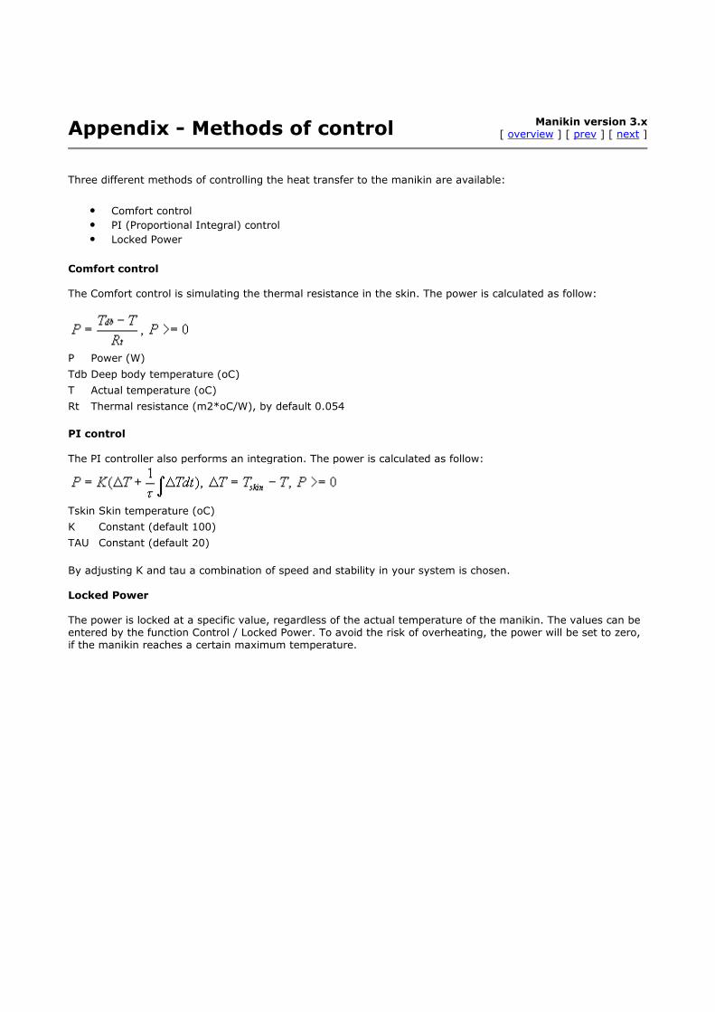
Three different methods of controlling the heat transfer to the manikin are available:
• Comfort control
• PI (Proportional Integral) control
• Locked Power
Comfort control The Comfort control is simulating the thermal resistance in the skin. The power is calculated as follow:
P Power (W)
Tdb Deep body temperature (oC)
T Actual temperature (oC)
Rt Thermal resistance (m2*oC/W), by default 0.054
PI control
The PI controller also performs an integration. The power is calculated as follow:
Tskin Skin temperature (oC)
K Constant (default 100)
TAU Constant (default 20)
By adjusting K and tau a combination of speed and stability in your system is chosen. Locked Power The power is locked at a specific value, regardless of the actual temperature of the manikin. The values can be entered by the function Control / Locked Power. To avoid the risk of overheating, the power will be set to zero, if the manikin reaches a certain maximum temperature.

Appendix - Clo calculation Manikin version 3.x
[ overview ] [ prev ] [ next ]
The following is a summary of:
Memorandum - Calculation of manikin clothing data George Havenith Loughborough 4 September 2002
There are three main calculation methods for manikin clothing insulation (heat resistance R). There is ongoing
debate on which should be used, with Umbach (D) pushing hard for the 'serial' approach detailed below. I think that we need all three calculations in the software, as the validity of each method changes with the measuring conditions (for Victoria it is different for the comfort setting [unequal skin temp.] than for equal skin temps over the body)
1 - Preliminary - Notations
Ti local skin temperature segment (i)
Ta ambient temperature
Tsk mean skin temperature
ai area fraction of segment (i) related to whole body area Ask ; ai = ask(i) / Ask note that : Tsk = S ai. Ti note that : Sai = 1 and therefore S (ai.Ta) = Ta
Hsk whole body heat flux (W/m2)
Hi local heat flux of segment (i) in W/m2
note that total heat flux for whole body (W/m2) is Hsk = S (ai . Hi)
Ri local resistance of segment (i)
2 - The general formula for defining whole body resistance (no consideration of parallel or serial here), which in my opinion meets best the definition of insulation in ISO 9920 is:
(equation A)
3 - If you make the assumption that skin temperature is uniform over the body, i.e. Ti = Tsk = constant, then equation (A) becomes:
(equation B)
This is adding up resistance according to a parallel model.
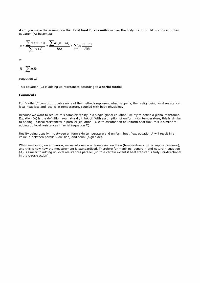
4 - If you make the assumption that local heat flux is uniform over the body, i.e. Hi = Hsk = constant, then equation (A) becomes:
or
(equation C)
This equation (C) is adding up resistances according to a serial model.
Comments
For "clothing" comfort probably none of the methods represent what happens, the reality being local resistance, local heat loss and local skin temperature, coupled with body physiology.
Because we want to reduce this complex reality in a single global equation, we try to define a global resistance. Equation (A) is the definition you naturally think of. With assumption of uniform skin temperature, this is similar to adding up local resistances in parallel (equation B). With assumption of uniform heat flux, this is similar to adding up local resistances in serial (equation C).
Reality being usually in-between uniform skin temperature and uniform heat flux, equation A will result in a value in-between parallel (low side) and serial (high side).
When measuring on a manikin, we usually use a uniform skin condition (temperature / water vapour pressure); and this is now how the measurement is standardised. Therefore for manikins, general - and natural - equation (A) is similar to adding up local resistances parallel (up to a certain extent if heat transfer is truly uni-directional in the cross-section).

Appendix - License agreement Manikin version 3.x
[ overview ] [ prev ] [ next ]
IMPORTANT: By installing, copying or otherwise using the manikin software, you agree to be bound by the
terms and conditions of this license agreement. If you do not agree to these terms and conditions, do not install, copy or otherwise use the manikin software.
Disclaimer of warrenties
To the maximum extent permitted by applicable law, BYTELINE and its suppliers provide the MANIKIN SOFTWARE and any (if any) support services related to the MANIKIN SOFTWARE ("Support Services") AS IS AND WITH ALL FAULTS, and hereby disclaim all warranties and conditions, either express, implied or statutory, including, but not limited to, any (if any) implied warranties or conditions of merchantability, of fitness for a
particular purpose, of lack of viruses, of accuracy or completeness of responses, of results, and of lack of negligence or lack of workmanlike effort, all with regard to the MANIKIN SOFTWARE, and the provision of or failure to provide Support Services. ALSO, THERE IS NO WARRANTY OR CONDITION OF TITLE, QUIET ENJOYMENT, QUIET POSSESSION, CORRESPONDENCE TO DESCRIPTION OR NON-INFRINGEMENT, WITH REGARD TO THE PRODUCT. THE ENTIRE RISK AS TO THE QUALITY OF OR ARISING OUT OF USE OR PERFORMANCE OF THE PRODUCT AND SUPPORT SERVICES, IF ANY, REMAINS WITH YOU.
Exclusion of incidental, consequential and certain other damages
To the maximum extent permitted by applicable law, in no event shall BYTELINE or its suppliers be liable for
any special, incidental, indirect, or consequential damages whatsoever (including, but not limited to, damages for loss of profits or confidential or other information, for business interruption, for personal injury, for loss of privacy, for failure to meet any duty including of good faith or of reasonable care, for negligence, and for any other pecuniary or other loss whatsoever) arising out of or in any way related to the use of or inability to use the MANIKIN SOFTWARE, the provision of or failure to provide Support Services, or otherwise under or in connection with any provision of Agreement, even in the event of the fault, tort (including negligence), strict liability, breach of contract or breach of warranty of BYTELINE or any supplier, and even if BYTELINE or any supplier has been advised of the possibility of such damages.
Limitation of liability and remedies
Notwithstanding any damages that you might incur for any reason whatsoever (including, without limitation, all damages referenced above and all direct or general damages), the entire liability of BYTELINE and any of its suppliers under any provision of this Agreement and your exclusive remedy for all of the foregoing shall be limited to the greater of the amount actually paid by you for the MANIKIN SOFTWARE or US $5. The foregoing limitations, exclusions and disclaimers shall apply to the maximum extent permitted by applicable law, even if any remedy fails its essential purpose.