management model for dsl line test · 01-05-2017 · sven ooghe nokia [email protected] . ......
TRANSCRIPT

TECHNICAL REPORT
© The Broadband Forum. All rights reserved.
TR-298
Management model for DSL line test
Issue: 02
Issue Date: March 2017

Management model for DSL line test TR-298 Issue 02
March 2017 © The Broadband Forum. All rights reserved 2 of 21
Notice
The Broadband Forum is a non-profit corporation organized to create guidelines for broadband
network system development and deployment. This Technical Report has been approved by
members of the Forum. This Technical Report is subject to change. This Technical Report is
copyrighted by the Broadband Forum, and all rights are reserved. Portions of this Technical
Report may be copyrighted by Broadband Forum members.
Intellectual Property
Recipients of this Technical Report are requested to submit, with their comments, notification of
any relevant patent claims or other intellectual property rights of which they may be aware that
might be infringed by any implementation of this Technical Report, or use of any software code
normatively referenced in this Technical Report, and to provide supporting documentation.
Terms of Use
1. License Broadband Forum hereby grants you the right, without charge, on a perpetual, non-exclusive and
worldwide basis, to utilize the Technical Report for the purpose of developing, making, having
made, using, marketing, importing, offering to sell or license, and selling or licensing, and to
otherwise distribute, products complying with the Technical Report, in all cases subject to the
conditions set forth in this notice and any relevant patent and other intellectual property rights of
third parties (which may include members of Broadband Forum). This license grant does not
include the right to sublicense, modify or create derivative works based upon the Technical Report
except to the extent this Technical Report includes text implementable in computer code, in which
case your right under this License to create and modify derivative works is limited to modifying
and creating derivative works of such code. For the avoidance of doubt, except as qualified by the
preceding sentence, products implementing this Technical Report are not deemed to be derivative
works of the Technical Report.
2. NO WARRANTIES
THIS TECHNICAL REPORT IS BEING OFFERED WITHOUT ANY WARRANTY
WHATSOEVER, AND IN PARTICULAR, ANY WARRANTY OF NONINFRINGEMENT IS
EXPRESSLY DISCLAIMED. ANY USE OF THIS TECHNICAL REPORT SHALL BE MADE
ENTIRELY AT THE IMPLEMENTER'S OWN RISK, AND NEITHER THE BROADBAND
FORUM, NOR ANY OF ITS MEMBERS OR SUBMITTERS, SHALL HAVE ANY LIABILITY
WHATSOEVER TO ANY IMPLEMENTER OR THIRD PARTY FOR ANY DAMAGES OF
ANY NATURE WHATSOEVER, DIRECTLY OR INDIRECTLY, ARISING FROM THE USE
OF THIS TECHNICAL REPORT.
3. THIRD PARTY RIGHTS Without limiting the generality of Section 2 above, BROADBAND FORUM ASSUMES NO
RESPONSIBILITY TO COMPILE, CONFIRM, UPDATE OR MAKE PUBLIC ANY THIRD
PARTY ASSERTIONS OF PATENT OR OTHER INTELLECTUAL PROPERTY RIGHTS
THAT MIGHT NOW OR IN THE FUTURE BE INFRINGED BY AN IMPLEMENTATION OF
THE TECHNICAL REPORT IN ITS CURRENT, OR IN ANY FUTURE FORM. IF ANY SUCH

Management model for DSL line test TR-298 Issue 02
March 2017 © The Broadband Forum. All rights reserved 3 of 21
RIGHTS ARE DESCRIBED ON THE TECHNICAL REPORT, BROADBAND FORUM TAKES
NO POSITION AS TO THE VALIDITY OR INVALIDITY OF SUCH ASSERTIONS, OR
THAT ALL SUCH ASSERTIONS THAT HAVE OR MAY BE MADE ARE SO LISTED.
The text of this notice must be included in all copies of this Technical Report.

Management model for DSL line test TR-298 Issue 02
March 2017 © The Broadband Forum. All rights reserved 4 of 21
Issue History
Issue Number Approval Date Publication Date Issue Editor Changes
1 27 June 2013 Daniel Cederholm
Ericsson
Original
2 13 March 2017 1 May 2017 Joey Boyd,
ADTRAN
Edited to align
with TR-355
Comments or questions about this Broadband Forum Technical Report should be directed to
Editors Joey Boyd ADTRAN [email protected]
FTTdp Work Area
Directors
Christopher Croot BT plc [email protected]
Sven Ooghe Nokia [email protected]

Management model for DSL line test TR-298 Issue 02
March 2017 © The Broadband Forum. All rights reserved 5 of 21
TABLE OF CONTENTS
EXECUTIVE SUMMARY ............................................................................................................. 7
1 PURPOSE AND SCOPE ......................................................................................................... 8
1.1 PURPOSE ............................................................................................................................. 8
1.2 SCOPE ................................................................................................................................. 8
2 REFERENCES AND TERMINOLOGY ............................................................................... 9
2.1 CONVENTIONS .................................................................................................................... 9 2.2 REFERENCES ....................................................................................................................... 9 2.3 ABBREVIATIONS ............................................................................................................... 10
3 TECHNICAL REPORT IMPACT ...................................................................................... 11
3.1 ENERGY EFFICIENCY ......................................................................................................... 11 3.2 IPV6 .................................................................................................................................. 11 3.3 SECURITY .......................................................................................................................... 11
3.4 PRIVACY ........................................................................................................................... 11
4 OBJECT MODEL FOR DSL LINE TEST ......................................................................... 12
5 OBJECT MODEL FOR SINGLE ENDED LINE TEST (SELT) ..................................... 13
5.1 SELT CONFIGURATION MODEL ......................................................................................... 13 5.1.1 SELT Configuration Vector ......................................................................................... 14
5.2 SELT RESULT PARAMETER MODEL ................................................................................... 15
6 OBJECT MODEL FOR DUAL ENDED LINE TEST (DELT) ........................................ 16
7 OBJECT MODEL FOR METALLIC LINE TEST (MELT) ............................................ 16
7.1 MELT CONFIGURATION MODEL ........................................................................................ 16
7.1.1 MELT Configuration Vector ........................................................................................ 17 7.2 MELT RESULT PARAMETER MODEL .................................................................................. 18

Management model for DSL line test TR-298 Issue 02
March 2017 © The Broadband Forum. All rights reserved 6 of 21
List of Figures
Figure 1: Functional reference model of DSL line test.................................................................... 12 Figure 2: Notations .......................................................................................................................... 13
Figure 3: SELT configuration model ............................................................................................... 14 Figure 4: SELT result parameter model ........................................................................................... 15 Figure 5: MELT configuration model.............................................................................................. 16 Figure 6: MELT result parameter model ......................................................................................... 19

Management model for DSL line test TR-298 Issue 02
March 2017 © The Broadband Forum. All rights reserved 7 of 21
Executive Summary
This Technical Report specifies a management model for DSL line tests containing the parameters
described in ITU-T Recommendation G.996.2 [2].

Management model for DSL line test TR-298 Issue 02
March 2017 © The Broadband Forum. All rights reserved 8 of 21
1 Purpose and Scope
1.1 Purpose
The purpose of this Technical Report is to provide a management model for ITU-T
Recommendation G.996.2 [2] and its Amendment 2 [3]. The management model is independent of
any protocol.
1.2 Scope
This Technical Report defines an object model for all the DSL line test parameters specified in
G.996.2. The object model specifies the structure of the managed objects, and the detailed
specifications of the parameters are given in G.996.2.

Management model for DSL line test TR-298 Issue 02
March 2017 © The Broadband Forum. All rights reserved 9 of 21
2 References and Terminology
2.1 Conventions
In this Technical Report, several words are used to signify the requirements of the specification.
These words are always capitalized. More information can be found be in RFC 2119 [1].
MUST This word, or the term “REQUIRED”, means that the definition is an
absolute requirement of the specification.
MUST NOT This phrase means that the definition is an absolute prohibition of the
specification.
SHOULD This word, or the term “RECOMMENDED”, means that there could
exist valid reasons in particular circumstances to ignore this item, but
the full implications need to be understood and carefully weighed
before choosing a different course.
SHOULD NOT This phrase, or the phrase "NOT RECOMMENDED" means that there
could exist valid reasons in particular circumstances when the
particular behavior is acceptable or even useful, but the full
implications need to be understood and the case carefully weighed
before implementing any behavior described with this label.
MAY This word, or the term “OPTIONAL”, means that this item is one of
an allowed set of alternatives. An implementation that does not
include this option MUST be prepared to inter-operate with another
implementation that does include the option.
2.2 References
The following references are of relevance to this Technical Report. At the time of publication, the
editions indicated were valid. All references are subject to revision; users of this Technical Report
are therefore encouraged to investigate the possibility of applying the most recent edition of the
references listed below.
A list of currently valid Broadband Forum Technical Reports is published at
www.broadband-forum.org.
Document Title Source Year
[1] RFC 2119 Key words for use in RFCs to Indicate
Requirement Levels
IETF 1997
[2] G.996.2 Single-ended line testing for digital
subscriber lines (DSL)
ITU-T 2009
[3] G.996.2 Single-ended line testing for digital ITU-T 2012

Management model for DSL line test TR-298 Issue 02
March 2017 © The Broadband Forum. All rights reserved 10 of 21
Amendment 2 subscriber lines (DSL) Amendment 2
[4] TR-252 Issue
2
xDSL Protocol-Independent
Management Model
BBF 2012
2.3 Abbreviations
This Technical Report uses the following abbreviations:
AC Alternating Current
DC Direct Current
DELT Dual Ended Line Test
DS Downstream
FE Far-End
FV Foreign Voltage
ME Management Entity
MELT Metallic Line Test
MMD Maximum Measurement Duration
PMD Physical Medium Dependent
QLN Quiet Line Noise
RG Ring to Ground
RT Ring to Tip
SELT Single Ended Line Test
SCV Signature Conduction Voltage
TG Tip to Ground
TR Tip to Ring
UER Uncalibrated Echo Response
US Upstream

Management model for DSL line test TR-298 Issue 02
March 2017 © The Broadband Forum. All rights reserved 11 of 21
3 Technical Report Impact
3.1 Energy Efficiency
TR-298 has no impact on energy efficiency.
3.2 IPv6
TR-298 has no impact on IPv6.
3.3 Security
TR-298 has no impact on security.
3.4 Privacy
Any issues regarding privacy are not affected by TR-298.

Management model for DSL line test TR-298 Issue 02
March 2017 © The Broadband Forum. All rights reserved 12 of 21
4 Object model for DSL line test
This specification is based on the parameters listed in G.996.2 and its Amendment 2. The object
model in this specification specifies the structure of the managed objects, and the detailed
parameter definitions and their access mode (read-only vs read-write) are specified in G.996.2.
Figure 1 shows the line test functional reference model defined in G.996.2. This model defines
several functional blocks representing different line test functions. There are two main categories
of functions; processing (P) and Physical Medium Dependent (PMD). The PMD functions are
related to measurements on the physical medium while the P functions are related to the processing
and transformation of the PMD results into derived parameters.
Line Under Test
Q interface
LT - ME - PMD - C
MIB
LT - ME - P - C
MIB
C ref point
C ref point
C ref point
LT - PMD - C
LT - P - C
OSS
U-C
G interface
LT - ME - PMD - R
MIB
LT - ME - P - R
MIB
R ref point
R ref point
R ref point
LT - PMD - R
LT - P - R T interface
ACS
Q interface
LT - ME - PMD - C
MIB
LT - ME - PMD - C
MIB
LT - ME - P - C
MIB
LT - ME - P - C
MIB
C ref point
C ref point
C ref point
LT - PMD - C
LT - P - C
OSS
G interface
LT - ME - PMD - R
MIB
LT - ME - P - R
MIB
R ref point
R ref point
R ref point
LT - PMD - R
LT - P - R T interface
ACS
U-R
Figure 1: Functional reference model of DSL line test
Note that the functional reference model in G.996.2 defines three different interfaces (Q, T and G)
and that each object in this specification is only available over some of these interfaces. The
parameters supported by each interface are listed in G.996.2 and will not be further discussed in
this Technical Report. It should also be noted that this Technical Report specifies full data models,
including all relevant standard configuration and status parameters. However, some of those
standard parameters are originally specified (e.g. G.996.2) as optional. While the structure and
content of the data models are mandatory, in practice an implementation might not support any
particular optional parameter. If the implementation does not support any optional parameter it
should still respond appropriately to read-write operations addressing it (e.g. by an error-code, by
returning a NULL value, etc.). The response type is beyond the scope of this Technical Report and
mainly depends on the specific management protocol being used.
The model uses the principle of Vector of Profiles (VoP) defined in Broadband Forum TR-252 [4].
This means that the configuration parameters are divided into independent profiles and that the
model uses pointers to these profiles.
Figure 2 illustrates notations used in this specification for illustrating the object model.

Management model for DSL line test TR-298 Issue 02
March 2017 © The Broadband Forum. All rights reserved 13 of 21
A
y
x
B
‘x’ instances of object A are logically related to ‘y’ instances of
object B. This may represent indirect relationship through other
objects.
A
y
B
Object A contains ‘y’ instances of object B. 1
A
B
Object A is a super-class with B and C as sub-classes
(inheritance relationship).
C
A
y
x
B
Object A contains pointers to ‘y’ instances of Object B.
Each instance of Object B is pointed to by ‘x’ instances of Object
A.
N+ : N or more instances
N..M : N to M instances
Figure 2: Notations
5 Object model for Single Ended Line Test (SELT)
The object model for SELT is divided into two submodels; One contains the configuration and
control parameters and one contains the result (measurement and derived) parameters.
5.1 SELT configuration model
The SELT configuration model includes all configuration related parameters from G.996.2 and
also the SELT-PMD control parameters used for triggering tests. The model is shown in
Figure 3.
The parameter names are taken from G.996.2 and its amendments which give the parameter
definitions. The supported types of measurements are Quiet Line Noise (QLN) and Uncalibrated
Echo Response (UER).
Management model for DSL line test TR-298 Issue 02
March 2017 © The Broadband Forum. All rights reserved 14 of 21
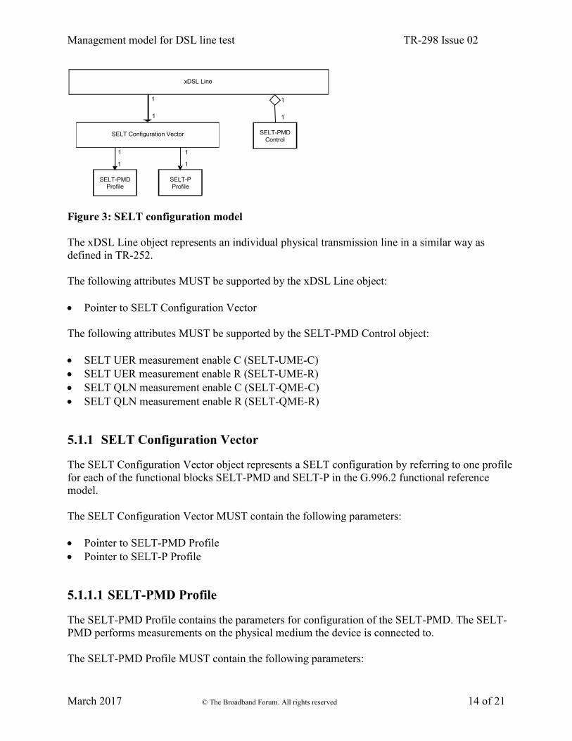
Figure 3: SELT configuration model
The xDSL Line object represents an individual physical transmission line in a similar way as
defined in TR-252.
The following attributes MUST be supported by the xDSL Line object:
Pointer to SELT Configuration Vector
The following attributes MUST be supported by the SELT-PMD Control object:
SELT UER measurement enable C (SELT-UME-C)
SELT UER measurement enable R (SELT-UME-R)
SELT QLN measurement enable C (SELT-QME-C)
SELT QLN measurement enable R (SELT-QME-R)
5.1.1 SELT Configuration Vector
The SELT Configuration Vector object represents a SELT configuration by referring to one profile
for each of the functional blocks SELT-PMD and SELT-P in the G.996.2 functional reference
model.
The SELT Configuration Vector MUST contain the following parameters:
Pointer to SELT-PMD Profile
Pointer to SELT-P Profile
5.1.1.1 SELT-PMD Profile
The SELT-PMD Profile contains the parameters for configuration of the SELT-PMD. The SELT-
PMD performs measurements on the physical medium the device is connected to.
The SELT-PMD Profile MUST contain the following parameters:
SELT Configuration Vector
SELT-PMD Profile
xDSL Line
SELT-P Profile
SELT-PMD
Control
1
1
1
1
1
1
1
1

Management model for DSL line test TR-298 Issue 02
March 2017 © The Broadband Forum. All rights reserved 15 of 21
SELT UER maximum measurement duration C (SELT_UER_MMD_C)
SELT UER maximum measurement duration R (SELT_UER_MMD_R)
SELT quiet line noise maximum measurement duration C (SELT_QLN_MMD_C)
SELT quiet line noise maximum measurement duration R (SELT_QLN_MMD_R)
5.1.1.2 SELT-P Profile
The SELT-P Profile contains the parameters for configuration of the SELT-P (Processing). The
SELT-P processes the results from SELT-PMD measurements and transforms them into derived
parameters representing the characteristics of the loop under test. The configuration parameters are
related to estimation of the achievable capacity on the loop.
The SELT-P Profile MUST contain the following parameters:
Capacity estimate calculation enabling (CECE)
Capacity estimate signal PSD downstream (CAP-SIGNALPSDds)
Capacity estimate signal PSD upstream (CAP-SIGNALPSDus)
Capacity estimate noise PSD downstream (CAP-NOISEPSDds)
Capacity estimate noise PSD upstream (CAP-NOISEPSDus)
Capacity estimate target noise margin downstream (CAP-TARSNRMds)
Capacity estimate target noise margin upstream (CAP-TARSNRMus)
5.2 SELT result parameter model
The SELT result parameter object represents all the results related to the SELT process. It contains
two sub-classes; one for the measured parameters in SELT-PDM and one for the derived
parameters in SELT-P.
The SELT result parameter model is illustrated in Figure 4.
Figure 4: SELT result parameter model
The SELT result parameter model MUST contain the following SELT-PMD measurement
parameters:
xDSL Line
SELT-P Derived parameters
SELT-PMD Measurement parameters
1
1
1
1

Management model for DSL line test TR-298 Issue 02
March 2017 © The Broadband Forum. All rights reserved 16 of 21
SELT uncalibrated echo response C (SELT-UER-C)
SELT uncalibrated echo response R (SELT-UER-R)
SELT variance of uncalibrated echo response C (SELT-UER-VAR-C)
SELT variance of uncalibrated echo response R (SELT-UER-VAR-R)
SELT quiet line noise C (SELT_QLN_C)
SELT quiet line noise R (SELT_QLN_R)
The SELT result parameter model MUST contain the following SELT-P derived parameters:
Loop termination indicator (LOOP-TERM)
Loop length (LOOP_LEN)
Loop topology (LOOP-TOPOLOGY)
Attenuation characteristics TFlog(f) (ATT-CHAR)
Missing micro-filter or splitter (MIS-FILTER)
Capacity estimate (CAP-EST)
6 Object model for Dual Ended Line Test (DELT)
DELT is currently for further study in G.996.2 and is thus for further study in this Technical
Report.
7 Object model for Metallic Line Test (MELT)
The object model for MELT is divided into two submodels; one contains the configuration and
control parameters and one contains the result (measurement and derived) parameters.
7.1 MELT configuration model
The MELT configuration model includes all configuration related parameters and also the MELT-
PMD control parameters used for triggering tests. The model is shown in Figure 5.
The parameter names are taken from G.996.2 and its amendments which give the parameter
definitions.
MELT Configuration Vector
MELT-PMD
Profile
xDSL Line
MELT-P Profile
MELT-PMD
Control
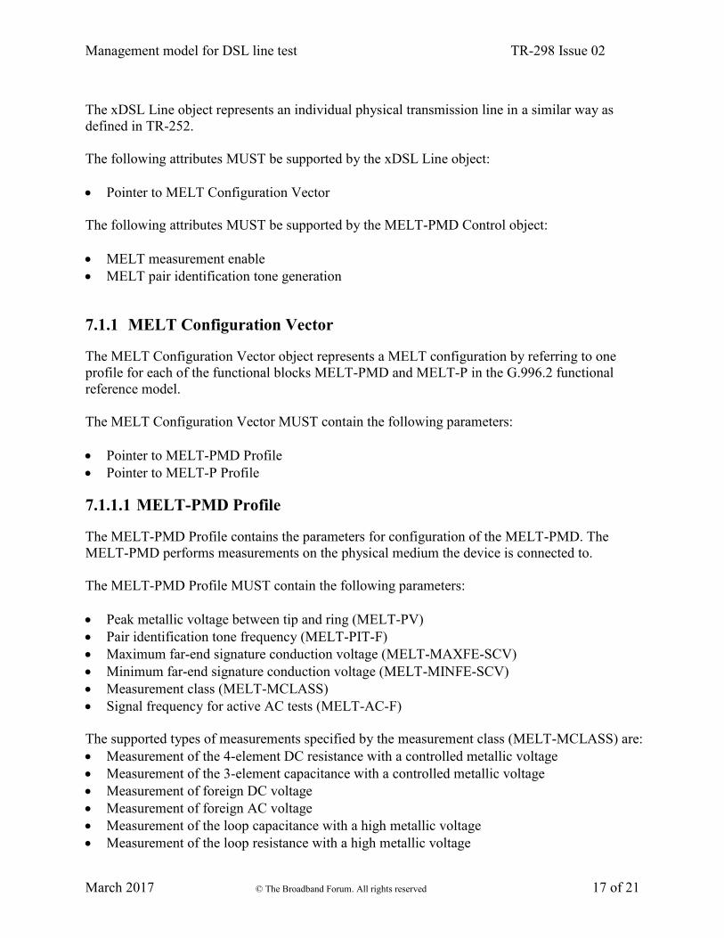
Figure 5: MELT configuration model
1
1
1
1
1
1
1
1
Management model for DSL line test TR-298 Issue 02
March 2017 © The Broadband Forum. All rights reserved 17 of 21
The xDSL Line object represents an individual physical transmission line in a similar way as
defined in TR-252.
The following attributes MUST be supported by the xDSL Line object:
Pointer to MELT Configuration Vector
The following attributes MUST be supported by the MELT-PMD Control object:
MELT measurement enable
MELT pair identification tone generation
7.1.1 MELT Configuration Vector
The MELT Configuration Vector object represents a MELT configuration by referring to one
profile for each of the functional blocks MELT-PMD and MELT-P in the G.996.2 functional
reference model.
The MELT Configuration Vector MUST contain the following parameters:
Pointer to MELT-PMD Profile
Pointer to MELT-P Profile
7.1.1.1 MELT-PMD Profile
The MELT-PMD Profile contains the parameters for configuration of the MELT-PMD. The
MELT-PMD performs measurements on the physical medium the device is connected to.
The MELT-PMD Profile MUST contain the following parameters:
Peak metallic voltage between tip and ring (MELT-PV)
Pair identification tone frequency (MELT-PIT-F)
Maximum far-end signature conduction voltage (MELT-MAXFE-SCV)
Minimum far-end signature conduction voltage (MELT-MINFE-SCV)
Measurement class (MELT-MCLASS)
Signal frequency for active AC tests (MELT-AC-F)
The supported types of measurements specified by the measurement class (MELT-MCLASS) are:
Measurement of the 4-element DC resistance with a controlled metallic voltage
Measurement of the 3-element capacitance with a controlled metallic voltage
Measurement of foreign DC voltage
Measurement of foreign AC voltage
Measurement of the loop capacitance with a high metallic voltage
Measurement of the loop resistance with a high metallic voltage

Management model for DSL line test TR-298 Issue 02
March 2017 © The Broadband Forum. All rights reserved 18 of 21
Measurement of the 3-element complex admittances with a controlled metallic voltage
Measurement of the loop complex admittance with a high metallic voltage
7.1.1.2 MELT-P Profile
The MELT-P Profile contains the parameters for configuration of the MELT-P (Processing). The
MELT-P processes the results from MELT-PMD measurements and transforms them into derived
parameters representing the characteristics of the loop under test. The supported types of MELT-P
derived parameters are:
Identification of an open wire failure
Open wire failure type
Distance to the open wire failure
Identification of a short circuit failure
Short circuit failure type
Leakage identification
Resistive fault identification
Foreign voltage classification
Foreign voltage type
Foreign voltage level class
Far-end signature topology identification
Far-end signature topology type
The MELT-P Profile MUST contain the following parameters:
Loop resistance classification threshold (MELT-LRC-TH)
Loop parameters per unit length (MELT-LOOP-PARAMS)
Hazardous DC voltage level (MELT-HDCV-L)
Hazardous AC voltage level (MELT-HACV-L)
Foreign EMF DC voltage level (MELT-FDCV-L)
Foreign EMF AC voltage level (MELT-FACV-L)
System capacitance at the CPE side (MELT-SYSC-CPE)
7.2 MELT result parameter model
The MELT result parameter object represents all the results related to the MELT test. It contains
two sub-classes; one for the measured parameters in MELT-PMD and one for the derived
parameters in MELT-P.
The MELT result parameter model is illustrated in Figure 6.

Management model for DSL line test TR-298 Issue 02
March 2017 © The Broadband Forum. All rights reserved 19 of 21
The MELT result parameter model MUST contain the following MELT-PMD reporting
parameters:
Measurement frequency for active AC tests (MELT-MFREQ)
Input impedance for foreign voltage measurements (MELT-IMP-V)
Measurement voltage for loop complex admittance with a high voltage test (MELT-HCA-V)
The MELT result parameter model MUST contain the following MELT-PMD measurement
parameters:
4-element DC resistance with controlled metallic voltage RTR (MELT-CDCR-TR)
4-element DC resistance with controlled metallic voltage RRT (MELT-CDCR-RT)
4-element DC resistance with controlled metallic voltage RTG (MELT-CDCR-TG)
4-element DC resistance with controlled metallic voltage RRG (MELT-CDCRRG)
3-element capacitance with controlled metallic voltage CTR (MELT-CC-TR)
3-element capacitance with controlled metallic voltage CTG (MELT-CC-TG)
3-element capacitance with controlled metallic voltage CRG (MELT-CC-RG)
Foreign DC voltage VTR,DC (MELT-FVDC-TR)
Foreign DC voltage VTG,DC (MELT-FVDC-TG)
Foreign DC voltage VRG,DC (MELT-FVDC-RG)
Foreign AC voltage VTR,AC (MELT-FVAC-TR)
Foreign AC voltage VTG,AC (MELT-FVAC-TG)
Foreign AC voltage VRG,AC (MELT-FVAC-RG)
Foreign AC voltage frequency FTR,AC (MELT-FVACF-TR)
Foreign AC voltage frequency FTG,AC (MELT-FVACF-TG)
Foreign AC voltage frequency FRG,AC (MELT-FVACF-RG)
Loop capacitance with high metallic voltage CTR,HV (MELT-HC-TR)
Loop resistance with high metallic voltage RTR,HV (MELT-HDCR-TR)
Loop resistance with high metallic voltage RRT,HV (MELT-HDCR-RT)
DC test voltage for the measurement of the 4-element DC resistance with a controlled metallic
voltage VDCTR (MELT-CDCV-TR)
DC test voltage for the measurement of the 4-element DC resistance with a controlled metallic
voltage VDCRT (MELT-CDCV-RT)
DC test voltage for the measurement of the 4-element DC resistance with a controlled metallic
voltage VDCTG (MELT-CDCV-TG)
Figure 6: MELT result parameter model
xDSL Line
MELT-P Derived parameters
MELT-PMD Measurement parameters
1
1
1
1

Management model for DSL line test TR-298 Issue 02
March 2017 © The Broadband Forum. All rights reserved 20 of 21
DC test voltage for the measurement of the 4-element DC resistance with a controlled metallic
voltage VDCRG (MELT-CDCV-RG)
Test current for the 4-element DC resistance with a controlled metallic voltage IDCTR
(MELT-CDCI-TR)
Test current for the 4-element DC resistance with a controlled metallic voltage IDCRT
(MELT-CDCI-RT)
Test current for the 4-element DC resistance with a controlled metallic voltage IDCTG
(MELT-CDCI-TG)
Test current for the 4-element DC resistance with a controlled metallic voltage IDCRG
(MELT-CDCI-RG)
Test voltage for the measurement of the loop resistance with a high metallic voltage VDCHTR
(MELT-HDCV-TR)
Test voltage for the measurement of the loop resistance with a high metallic voltage VDCHRT
(MELT-HDCV-RT)
Measurement voltage VACTR-CC (MELT-ACV-CC-TR)
Measurement voltage VACTG-CC (MELT-ACV-CC-TG)
Measurement voltage VACRG-CC (MELT-ACV-CC-RG)
Measurement voltage VACTR-HC (MELT-ACV-HC-TR)
Measurement voltage VACTR-CA (MELT-ACV-CA-TR)
Measurement voltage VACTG-CA (MELT-ACV-CA-TG)
Measurement voltage VACRG-CA (MELT-ACV-CA-RG)
Measurement voltage VACTR-HA (MELT-ACV-HA-TR)
3-element complex admittance with controlled metallic voltage real part GTR (MELT-CAG-
TR)
3-element complex admittance with controlled metallic voltage imaginary part BTR (MELT-
CAB-TR)
3-element complex admittance with controlled metallic voltage real part GTG (MELT-CAG-
TG)
3-element complex admittance with controlled metallic voltage imaginary part BTG (MELT-
CAB-TG)
3-element complex admittance with controlled metallic voltage real part GRG (MELT-CAG-
RG)
3-element complex admittance with controlled metallic voltage imaginary part BRG (MELT-
CAB-RG)
Loop complex admittance with high metallic voltage real part GTR,HV (MELTHAG-TR)
Loop complex admittance with high metallic voltage imaginary part BTR,HV (MELT-HAB-
TR)
The MELT result parameter model MUST contain the following MELT-P derived parameters:
Identification of an open wire failure (MELT-O-WIRE-type) – Open wire failure Type
Identification of an open wire failure (MELT-O-WIRE-DIST) – Distance to the open wire
failure
Identification of a short circuit failure type (MELT-S-CCT-type)
Leakage identification (MELT-LEAK-ID)

Management model for DSL line test TR-298 Issue 02
March 2017 © The Broadband Forum. All rights reserved 21 of 21
Resistive fault identification (MELT-RFAULT-ID)
Foreign voltage type classification (MELT-FV-TYPE)
Foreign voltage level classification (MELT-FV-LEVEL)
Far-end signature topology type identification (MELT-FES-ID)
End of Broadband Forum Technical Report TR-298