man packable power systems 050305 - source
TRANSCRIPT

Man Packable Power Systems:
An Assessment of Current & Future Fuel Cell Technologies
Ken Burt Rudy Pirani Scott Blattert NSWC Crane; Code 6095 NSWC Crane; Code 6095 NSWC Crane; Code 6095 [email protected] [email protected] [email protected] 300 Highway 361, Bldg 3287 300 Highway 361, Bldg 3287 300 Highway 361, Bldg 3287 Crane, IN 47522 Crane, IN 47522 Crane, IN 47522
Making Sea Power 21 a Reality
Points of Contact:
http://www.crane.navy.mil
Distribution Statement A Approved for public release; distribution unlimited

Approved for Public Release; Distributed Unlimited
Today’s Performance
Approved for Public Release; Distributed Unlimited
Focus Area Lead
Shared/Leveraged Knowledge
Focus Area Follow
Legend:
Common Area:FC Stack / TypesAccessoriesElectrodesMembranesSafety IssuesModelingTechnology Assessment
NUWC-NPTAir Independent
6.1 - 6.4UUVs, Torpedoes, CMs,
TargetsAir-Independent
Specialty Fuels / OxidizersSeawater activated
NSWC-CD6.1-6.6
Air Breathing
Surface ShipsSubmarines
Distributed Power SystemsShore Based Power
Reformers
NSWC-Crane6.3 -6.5
Air BreathingMan Portable PowerUAVSubmersiblesEnvironmental Testing Expeditionary PowerAircraftField Support
Shore
Expeditionary
Submersibles
ReformingMaterialsTechnology
UUVs
Focus Area Lead
Shared/Leveraged Knowledge
Focus Area Follow
Legend:
Focus Area Lead
Shared/Leveraged Knowledge
Focus Area Follow
Legend:
Common Area:FC Stack / TypesAccessoriesElectrodesMembranesSafety IssuesModelingTechnology Assessment
NUWC-NPTAir Independent
6.1 - 6.4UUVs, Torpedoes, CMs,
TargetsAir-Independent
Specialty Fuels / OxidizersSeawater activated
NSWC-CD6.1-6.6
Air Breathing
Surface ShipsSubmarines
Distributed Power SystemsShore Based Power
Reformers
NSWC-Crane6.3 -6.5
Air BreathingMan Portable PowerUAVSubmersiblesEnvironmental Testing Expeditionary PowerAircraftField Support
Shore
Expeditionary
Submersibles
ReformingMaterialsTechnology
UUVs Common Area:FC Stack / TypesAccessoriesElectrodesMembranesSafety IssuesModelingTechnology Assessment
NUWC-NPTAir Independent
6.1 - 6.4UUVs, Torpedoes, CMs,
TargetsAir-Independent
Specialty Fuels / OxidizersSeawater activated
NSWC-CD6.1-6.6
Air Breathing
Surface ShipsSubmarines
Distributed Power SystemsShore Based Power
Reformers
NSWC-Crane6.3 -6.5
Air BreathingMan Portable PowerUAVSubmersiblesEnvironmental Testing Expeditionary PowerAircraftField Support
Shore
Expeditionary
Submersibles
ReformingMaterialsTechnology
UUVs
NUWC-NPTAir Independent
6.1 - 6.4UUVs, Torpedoes, CMs,
TargetsAir-Independent
Specialty Fuels / OxidizersSeawater activated
NUWC-NPTAir Independent
6.1 - 6.4UUVs, Torpedoes, CMs,
TargetsAir-Independent
Specialty Fuels / OxidizersSeawater activated
NSWC-CD6.1-6.6
Air Breathing
Surface ShipsSubmarines
Distributed Power SystemsShore Based Power
Reformers
NSWC-CD6.1-6.6
Air Breathing
Surface ShipsSubmarines
Distributed Power SystemsShore Based Power
Reformers
NSWC-Crane6.3 -6.5
Air BreathingMan Portable PowerUAVSubmersiblesEnvironmental Testing Expeditionary PowerAircraftField Support
NSWC-Crane6.3 -6.5
Air BreathingMan Portable PowerUAVSubmersiblesEnvironmental Testing Expeditionary PowerAircraftField Support
Shore
Expeditionary
Submersibles
ReformingMaterialsTechnology
UUVs
Joint Service Power Exposition 2-5 May 2005
Man Packable Power Systems:
An Assessment of Current & Future Fuel Cell Technologies Ken Burt Rudy Pirani Scott Blattert NSWC Crane NSWC Crane NSWC Crane [email protected] [email protected] [email protected] 300 Highway 361, Bldg 3287 Crane, IN 47522
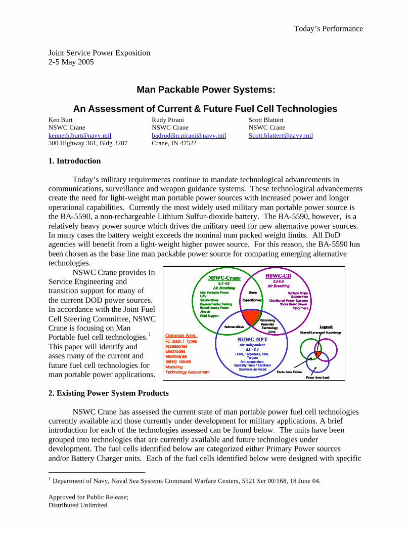
1. Introduction Today’s military requirements continue to mandate technological advancements in communications, surveillance and weapon guidance systems. These technological advancements create the need for light-weight man portable power sources with increased power and longer operational capabilities. Currently the most widely used military man portable power source is the BA-5590, a non-rechargeable Lithium Sulfur-dioxide battery. The BA-5590, however, is a relatively heavy power source which drives the military need for new alternative power sources. In many cases the battery weight exceeds the nominal man packed weight limits. All DoD agencies will benefit from a light-weight higher power source. For this reason, the BA-5590 has been chosen as the base line man packable power source for comparing emerging alternative technologies. NSWC Crane provides In Service Engineering and transition support for many of the current DOD power sources. In accordance with the Joint Fuel Cell Steering Committee, NSWC Crane is focusing on Man Portable fuel cell technologies.1 This paper will identify and asses many of the current and future fuel cell technologies for man portable power applications.
2. Existing Power System Products NSWC Crane has assessed the current state of man portable power fuel cell technologies currently available and those currently under development for military applications. A brief introduction for each of the technologies assessed can be found below. The units have been grouped into technologies that are currently available and future technologies under development. The fuel cells identified below are categorized either Primary Power sources and/or Battery Charger units. Each of the fuel cells identified below were designed with specific
1 Department of Navy, Naval Sea Systems Command Warfare Centers, 5521 Ser 00/168, 18 June 04.

Today’s Performance
Approved for Public Release; Distributed Unlimited
mission and power interest in mind. Each manufacture has tailored his/her system’s power ratings, fuel, fuel cartridge and other design criteria to fulfill specific focus areas. This accounts for the variety of sizes, types and capabilities of the fuel cells.
The physical, electrical and design characteristics of the fuel cells assessed, current and projected properties, are provided in section 3.3, Tables 1-6. The current technology data provided in Tables 1-3 was obtained from multiple sources as indicated in the Tables.
The initial intent of this assessment was to evaluate all of the currently available fuel cell technologies at NSWC using a standard test profile and to provide the assessment results in an “apples to apples” volumetric/gravimetric comparison. Due to delivery schedules, product operational status and numerous other reasons only two of the fuel cell technologies were actually evaluated at NSWC Crane (AMI Gen 1.9 and Protonex P1). NSWC Crane was also able to examine the BB-2590 and the BA-8180. Army Research Laboratory provided government test data for the Giner GES 120 fuel cell. Actual test data was provided by Smart Fuel Cell for the C-20 and A50 fuel cells. All other data was provided/projected by the fue l cell manufacturers.
2.1 Current Technologies
2.1.1 Primary Li/SO2 Battery (BA-5590)
The BA-5590 is a fully qualified non-rechargeable Li/SO2 battery that has been used for military applications for the past 10-15 years. The BA-5590 is used for numerous soldier power applications such as radios, laptops, and laser designators. The BA-5590 is simple, safe, provides no audible and little thermal signature and operates from –20 to +50°C. The BA-5590 has a large supply/manufacturing base that allows for stable prices and availability from commercial sources. However, due to the
continually increasing power needs, the BA-5590 is becoming a limiting factor to mission capability. Power is also a limiting factor in some equipment, requiring multiple batteries having a 2.25-amp fuse on each string that renders a fresh battery useless if current is overdrawn. The BA 5590 physical, electrical and environmental characteristics are tabulated in section 3.3, Tables 1-3. 2.1.2 Rechargeable Li-Ion Battery (BB-2590)
The BB-2590 is the lithium-ion rechargeable counterpart of the BA-5590. It adheres to the same performance specifications as the BA-5590, except the BB 2590 weighs approximately 30% more than the BA 5590 for roughly the same energy. The BB-2590 can also operate at approximately twice the power of the BA-5590. Brentronics is currently the sole-source supplier of the Defense Logistics Agency’s (DLA) BB-2590. The
manufacturer recommended charge profile specifies that each section of the battery be charged independently at a constant voltage of 16.5 Volts at 3 amps (max) for 5 hours. Brentronics also provides fully qualified military battery chargers for the BB-2590. Ultralife2 has expressed
2 Ultralife; Product Data Sheet, http://www.ultralifebatteries.com

Today’s Performance
Approved for Public Release; Distributed Unlimited
interest in manufacturing the BB-2590 when the sole-source contract with Brentronics ends. The physical, electrical and environmental characteristics of the BA 5590 are tabulated in Tables 1-3. 2.1.3 Zinc-Air Battery (BA-8180)
The BA-8180 is a Zinc-Air non-rechargeable battery/semi-fuel cell developed by Electric Fuel and fielded by the Army for higher energy storage rated at 350 whr/kg, but roughly 250 whr/kg in practice. The BA-8180 has the capability to be used as either a primary power pack or a battery charger depending upon the application needs. A variety of adaptor interface kits have been developed and are available for system
interfacing. The Zinc-Air battery uses air to react Zinc with oxygen. The BA-8180 has a high self-discharge rate and limited power capability. The BB-8180 is used primarily for field battery charging. While exposed to the air, the user has only a limited time to utilize the battery before its capacity is drained. The adaptor includes pins for an internal air blower that provides cathode air at higher power output, normally turned on automatically by mating to the equipment connector. The BA-8180 physical, electrical and environmental characteristics are tabulated in section 3.3, Tables 1-3. 2.1.4 Protonex 30W PEM (DUS&T P1)
Protonex, under contract with the Air Force Research Lab (AFRL), Capt. David Pfahler, is developing a 30-watt Proton Exchange Membrane (PEM) fuel cell system. The system, known as Dual Use Science and Technology (DUS&T) P1, uses Millennium Cell Inc. technology to obtain hydrogen on demand from a fully contained Sodium Borohydride (SBH) fuel source. The hydrogen depleted Sodium Borohydride (Sodium Borate)
is stored in a separate compartment within the fuel container for safe disposal, therefore, the P1 system does not loose weight as the fuel supply is depleted. Cathode water is generated, stored, and removed with a syringe. The P1contains three small Ni-Cd batteries for system start-up but the P1 currently has no hybrid battery for power output. Power output is direct from the stack, and therefore excessive load pulses may damage the fuel cell. The fuel cell was developed as a 30-watt fuel cell system for small battery charger applications. The P1 is currently at a technology readiness level of 4 to 5. A representative prototype was delivered to AFRL in Feb/05 and is currently under evaluation. Protonex provided technical responses to NSWC Crane indicating that the current system has demonstrated 200+ hours of system operation on SBH and 1000+ hours operation on hydrogen. Protonex also indicated that the stacks have 4000+ hours demonstrated. The DUS&T P1 physical, electrical and environmental characteristics are tabulated in section 3.3, Tables 1-3.
2.1.5 Adaptive Material Inc 20W SOFC (Generation 1.9)
Adaptive Material Inc (AMI), under contract with the Defense Advanced Research Projects Agency (DARPA)/Palm Power, Dr. Valerie Browning, is developing a 20-watt Solid Oxide Fuel Cell (SOFC) system that will operate on a commercial grade propane fuel source. The AMI Generation

Today’s Performance
Approved for Public Release; Distributed Unlimited
1.9 system is currently at a technology readiness level of 4-5. Prototype fuel cells are planned for demonstration summer 2005. Generation 2.0 units are scheduled for delivery to DARPA Dec/06. AMI provided technical responses to NSWC Crane indicating that the current system has demonstrated 100+ hours operational life and that the stack has demonstrated 300+ hours operation. The system uses an detached fuel tank connected to the fuel cell through an umbilical fuel supply tube. The umbilical design allows flexibility when selecting the fuel tank. The existing design is hybridized with a 23Watt-hour Lithium Ion battery for system start-up and to provide power during cold start. The hybrid design also allows the fuel cell to provide strenuous, sustained and repetitive pulse profiles when used as a primary power source. The physical, electrical and environmental characteristics can be found in section 3.3, Tables 1-3 2.1.6 Giner 120W DMFC (GES 120)
Giner, under contract with the Army Research Lab (ARL), Dr. Deryn Chu, has developed the GES 120, a 120-watt Direct Methanol Fuel Cell (DMFC) operating on a methanol/water mix fuel source. The system contains two small refillable tanks used to supply fuel; the first tank is a 250 cc tank for a 100% methanol fuel, the second tank is a 400 cc water reservoir. During normal operations, the system generates and captures most, if not all of the water that it needs, depending on operating
conditions. This type of water management system gives the Giner GES flexibility to operate in a variety of dry environments without adding water to the fuel. The Giner system is targeted as a portable power system for charging batteries in the field. The Giner system is currently at a technology readiness level of 4 - 5. A representative prototype has been operating at ARL since Jan/04. ARL has indicated that system has demonstrated 200+ hours operation while at ARL. The GES 120 physical, electrical and environmental characteristics are tabulated in section 3.3, Tables 1-3. 2.1.7 Smart Fuel Cell 20W DMFC (C-20)
Smart Fuel Cell (SFC), under contract with the Communications Electronics Research Development & Engineering Center (CERDEC), Mr. Nick Sifer, is developing a 20-watt Direct Methanol Fuel Cell (DMFC) system known as the C-20. The C-20 operates on a 100% methanol fuel source with an internal water management system to eliminate external fuel mixing. The C-20 system was designed to provide a man portable
power source for direct power use. The C-20 system is currently at a technology readiness level of 5-7 pending test and evaluations in process at CERDEC. Representative second generation prototypes were delivered to CERDEC Apr/05. SFC has indicated that the C20 has demonstrated 1650+ hours operation with 2000+ hours demonstrated for the stack. An internal18Wh Lithium Polymer battery is used for system start-up and to handle power spike requirements. The C-20 physical, electrical and environmental characteristics are tabulated in section 3.3, Tables 1-3. 2.1.8 Smart Fuel Cell 50W DMFC (A-50)
Today’s Performance
Approved for Public Release; Distributed Unlimited
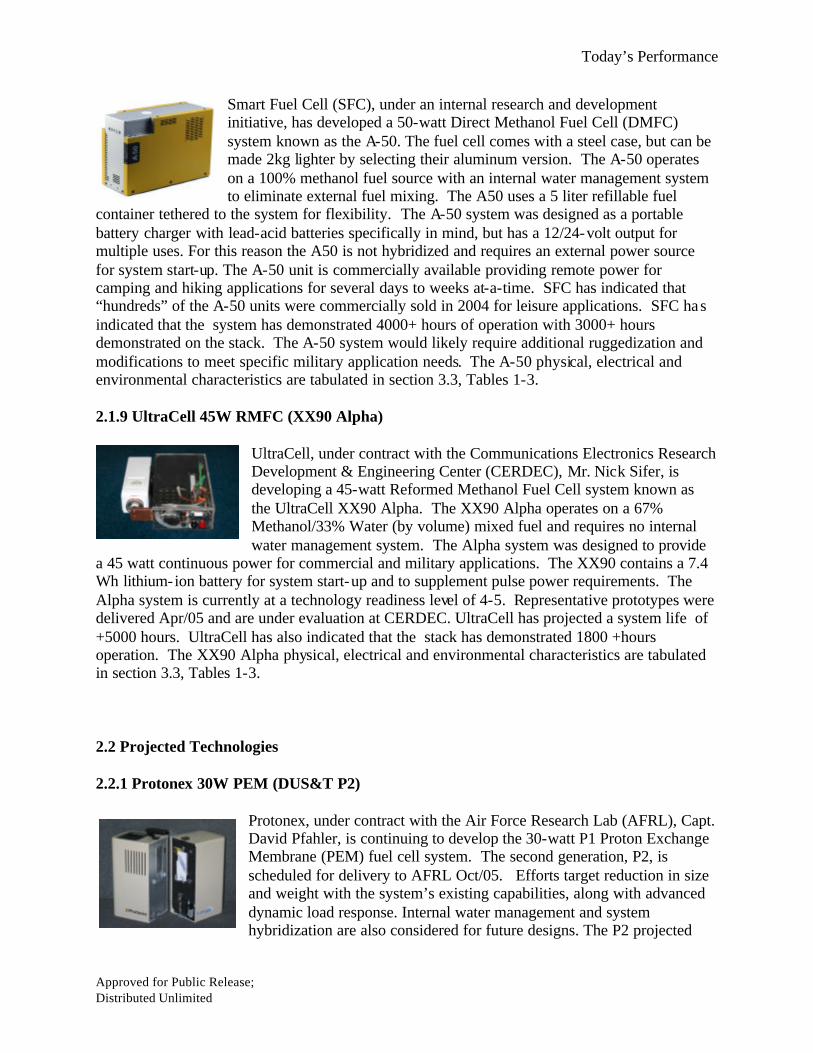
Smart Fuel Cell (SFC), under an internal research and development initiative, has developed a 50-watt Direct Methanol Fuel Cell (DMFC) system known as the A-50. The fuel cell comes with a steel case, but can be made 2kg lighter by selecting their aluminum version. The A-50 operates on a 100% methanol fuel source with an internal water management system to eliminate external fuel mixing. The A50 uses a 5 liter refillable fuel
container tethered to the system for flexibility. The A-50 system was designed as a portable battery charger with lead-acid batteries specifically in mind, but has a 12/24-volt output for multiple uses. For this reason the A50 is not hybridized and requires an external power source for system start-up. The A-50 unit is commercially available providing remote power for camping and hiking applications for several days to weeks at-a-time. SFC has indicated that “hundreds” of the A-50 units were commercially sold in 2004 for leisure applications. SFC has indicated that the system has demonstrated 4000+ hours of operation with 3000+ hours demonstrated on the stack. The A-50 system would likely require additional ruggedization and modifications to meet specific military application needs. The A-50 physical, electrical and environmental characteristics are tabulated in section 3.3, Tables 1-3.
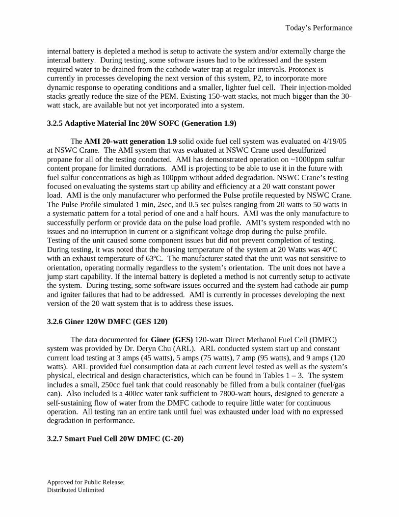
2.1.9 UltraCell 45W RMFC (XX90 Alpha)
UltraCell, under contract with the Communications Electronics Research Development & Engineering Center (CERDEC), Mr. Nick Sifer, is developing a 45-watt Reformed Methanol Fuel Cell system known as the UltraCell XX90 Alpha. The XX90 Alpha operates on a 67% Methanol/33% Water (by volume) mixed fuel and requires no internal water management system. The Alpha system was designed to provide
a 45 watt continuous power for commercial and military applications. The XX90 contains a 7.4 Wh lithium-ion battery for system start-up and to supplement pulse power requirements. The Alpha system is currently at a technology readiness level of 4-5. Representative prototypes were delivered Apr/05 and are under evaluation at CERDEC. UltraCell has projected a system life of +5000 hours. UltraCell has also indicated that the stack has demonstrated 1800 +hours operation. The XX90 Alpha physical, electrical and environmental characteristics are tabulated in section 3.3, Tables 1-3.
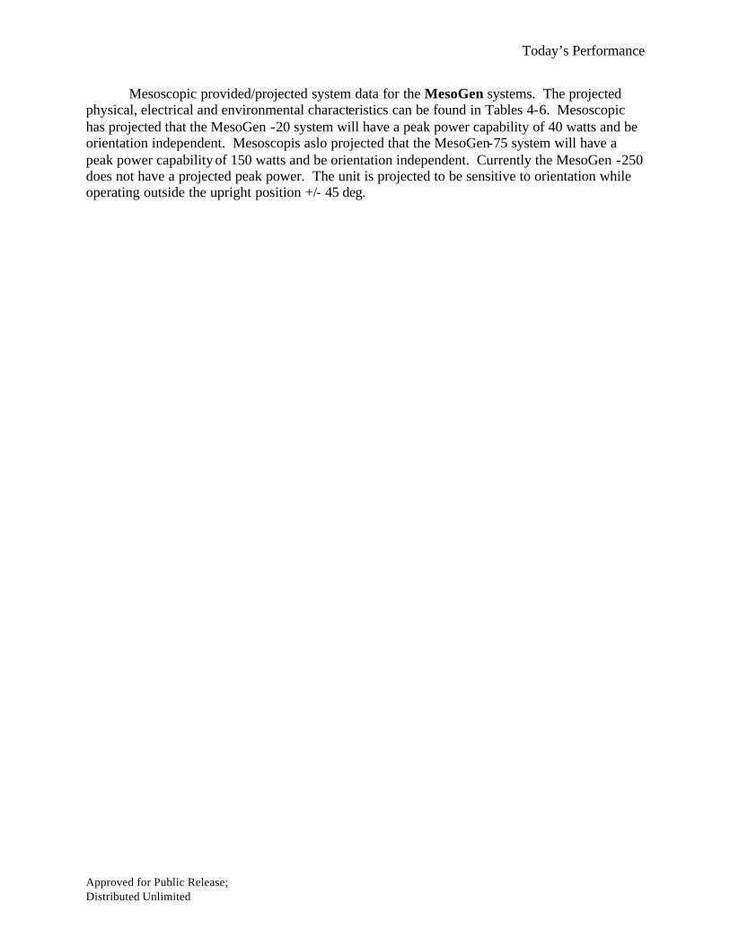
2.2 Projected Technologies 2.2.1 Protonex 30W PEM (DUS&T P2)
Protonex, under contract with the Air Force Research Lab (AFRL), Capt. David Pfahler, is continuing to develop the 30-watt P1 Proton Exchange Membrane (PEM) fuel cell system. The second generation, P2, is scheduled for delivery to AFRL Oct/05. Efforts target reduction in size and weight with the system’s existing capabilities, along with advanced dynamic load response. Internal water management and system hybridization are also considered for future designs. The P2 projected

Today’s Performance
Approved for Public Release; Distributed Unlimited
physical, electrical and environmental characteristics are tabulated in section 3.3, Tables 4-6. 2.2.2 Adaptive Material Inc 20W SOFC (Generation 2)
AMI, under contract with the Defense Advanced Research Agency (DARPA)/Palm Power, Dr. Valerie Browning, is continuing the developing of the Gen 1.9 SOFC. Efforts are focused on weight and size reduction, as well as inclusion of more efficient components and another iteration of system optimization. Gen 2.0 will use a commercial grade propane as the fuel source. The projected data for AMI Generation 2.0
system is based on the continuing efforts being made on the Generation 1.9 Solid Oxide system. The AMI Generation 2.0 system is scheduled for delivery in Dec/06. The Gen 2 projected physical, electrical and environmental characteristics are tabulated in section 3.3, Tables 4-6. 2.2.3 Smart Fuel Cell 50W DMFC (C-50)
Smart Fuel Cell (SFC), under internal research and development with an undisclosed partner, are developing a 50-watt version of their C-20 Direct Methanol Fuel Cell (DMFC) system. The C-50, like the C-20, will use a 100% methanol fuel source and internal water management system. The major advancement is the replacement of the membrane electrode assembly with a monopolar design. The C-50 system was designed to
provide a man portable power source for direct power use. The C-50 DMFC units have not been evaluated by a known U.S. DoD agency; however, SFC has indicated that the C-50 unit is at a TRL 4. The C-50 projected physical properties, electrical and environmental characteristics are tabulated in section 3.3, Tables 4-6. 2.2.4 Mesoscopic 20W DMFC (MesoGen-20)
Mesoscopic, under contract with the Army Research Lab (ARL), Dr. Deryn Chu, is developing a 20-watt Direct Methanol Fuel Cell (DMFC), monopolar MEA system, known as the MesoGen –20. The MesoGen-20 will use a 100% methanol fuel source with internal water management. The MesoGen -20 system is being designed to provide a man portable power source for direct power use. The system is currently at a
technology readiness level of 4. A representative prototype, Generation 1, has been developed and tested in a laboratory environment. The Generation 1 system is being used as a test bed for modifications planned for the next generation model. The Generation 2 system is expected to be completed in the Fall of 2005. Projected physical, electrical and environmental characteristics can be found in section 3.3, Tables 4-6. 2.2.5 Mesoscopic 75W SOFC (MesoGen-75)
Mesoscopic, under contract with the Defense Advanced Research Agency (DARPA)/Palm Power, Dr. Valerie Browning, is developing a 75-watt Solid Oxide Fuel Cell, known as the MesoGen-75. The MesoGen-75 will

Today’s Performance
Approved for Public Release; Distributed Unlimited
operate on a desulfurized JP-8 fuel source. The MesoGen -75 system is being designed to provide a portable power source for charging batteries in the field. The system is currently at a technology readiness level of 3. A representative prototype, Generation 1, has been developed and tested at 50 watts in a laboratory environment. Two Generation 2 systems are currently being developed, one will operate on desulfurized propane and the second on propane. The Gen 2 units are scheduled for delivery to DARPA in Jun/05. The propane system will incorporate a 24V option that uses a DC-DC converter and will have a nominal power of 50 watts with a slightly higher weight than the future projected estimates. Planned developments will increase power output to the full 75-watts. The MesoGen-75 projected physical, electrical and environmental characteristics are tabulated in section 3.3, Tables 4-6. 2.2.6 Mesoscopic 250W SOFC (MesoGen-250)
Mesoscopic, under contract with the Office of Naval Research, Major Alan Stocks, is developing a 250-watt Solid Oxide Fuel Cell, known as the MesoGen-250. The MesoGen-250 will operate on a desulfurized JP-8 fuel source, provided by a second liquid desulfurizer unit. Mesoscopic Devices is also developing a small field deployable desulfurizer unit for JP-8 field desulfurizing. The MesoGen-250 system will be designed to
provide a portable power source for charging batteries in the field. The system is currently at a technology readiness level of 2. The MesoGen-250 system development was started in the spring of 2005. Only preliminary predictions for performance and physical characteristics are available at this time. The MesoGen-250 projected physical, electrical and environmental characteristics are tabulated in section 3.3, Tables 4-6. 2.3.7 UltraCell 45W RMFC (XX90 EVT)
UltraCell, under contract with the Communications Electronics Research Development & Engineering Center (CERDEC), Mr. Nick Sifer, will continue the XX90 Alpha development effort with a 45-watt Reformed Methanol Fuel Cell system known as the UltraCell XX90 EVT. The XX90 EVT will use a 67% Methanol/33% Water (by volume) mixed fuel. A representative prototype is under development with CERDEC and is scheduled for delivery in Oct/05. UltraCell projects the system life for 5000+ hours operation. Ultra Cell has also stated that the stacks have been
demonstrated 1800+ hours operational life. The XX90 EVT projected physical, electrical and environmental characteristics are tabulated in section 3.3, Tables 4-6. 3. Test Profiles and Data Collection
NSWC Crane generated two test load profiles for this comparison effort. The first test profile is a primary power profile and the second a battery charger profile. The profiles, detailed in 3.1 – 3.2, DO NOT represent any single equipment load profile, but rather a set of challenges that allow for characterization of the system’s ability to handle most power and pulse power demands. The profiles were designed to provide generic comparison data for each of the different power systems examined.

Today’s Performance
Approved for Public Release; Distributed Unlimited
NSWC Crane’s goal was to evaluate each system and subsystem components and obtain data on the unit’s operation ability and efficiency, however, many of the fuel cell manufacturers were unable to provide units for the evaluation due to delivery schedules, prototype availability issues and other assorted issues.
Two manufacturers were able to provide fuel cells for the evaluation: AMI and Protonex. ARL provided test data for the Giner fuel cell, SFC provided test data for the C-20 and the A-50 fuel cells. All other data was provided/projected by the respective fuel cell manufacturers. AMI was the only manufacturer to attempt the pulse section of the primary power test profile. 3.1 Load Profiles 3.1.1 Primary Power Profile
The Primary Power profile first examined the units characteristics during start up. A load
based on 100% of the unit’s nominal power rating was applied to the unit before the system was turned on. Once the fuel cell system was activated, it was documented when power was provided, when the stack was providing 75% of the load and when the stack was providing 100% of the load. The profile required the system to provide 100% power load (based on the units nominal power rating) for one hour. At the end of the hour the unit would provide power for a 20 watt continuous load for an additional hour. Following the continuous load profiles the Pulse Profile would be conducted. The Pulse Profile simulated 1 min, 2sec, and 0.5 sec pulses ranging from 100% rated load to 250% rated load in a systematic pattern for a total period of one and a half hours.
3.1.2 Battery Charger Profile
The Battery Charger profile first examined the fuel cells characteristics during start up.
A load based on 100% of the unit’s nominal power rating was applied to the unit before the system was turned on. Once the fuel cell system was activated, it was documented when power was provided, when the stack was providing 75% of the load and when the stack was providing 100% of the load. The profile required the system to provide a 100% power load (based on the units nominal power rating) for one hour. At the end of the hour the unit would provide power for a 20 watt continuous load for an additional hour. The power load would be then set for a 50 watts continuous load for an additional hour and increased by a 25 watts increment for an additional one hour time frame until the fuel cell reached its peck power load.
3.2 Data Collection and Observations The data collected is represented in Tables 1 – 6 ; color highlights indicate the nature of the data source. The data sources are identified as government test data, manufacturer test data, or manufacturer provided specifications. The data collected and observations are as follows: 3.2.1 Primary Li/SO2 Battery (BA-5590)

Today’s Performance
Approved for Public Release; Distributed Unlimited
The data used for the BA-5590 projections was obtained from the MIL-Power3 specification sheet for the BA-5590 and other manufacturer data sheets. This information was used to project the volumetric/gravimetric requirements of the BB 5590 in all missions within this paper. 3.2.2 Rechargeable Li-Ion Battery (BB-2590) The electrical and physical characteristics of the BB-2590 are based on specifications, validated by manufacturer test data.4 The physical properties detailed in Table 2, were measured for a Brentronics BB-2590 evaluated at NSWC Crane. The BB-2590 energy is derated for cycle life loss (up to 80% end-of- life), and because the BB-2590 at 100% state-of-charge (SOC) is rated for 12.8 Ahr/string, while the BA-5590 is rated for 14.4 Ahr, the BB-2590 was elected to have 80% of the energy of a BA-5590 for evaluation calculations. BB-2590’s achieve much longer cycle lifes when discharged between 20 to 80% rathe r than 100% depth of discharge (DOD), with the effect of lower DODs being more frequent charge/discharge change-outs during operations, not accounted for in this evaluation. 3.2.3 Zinc-Air Battery (BA-8180) Data for the BA-8180s was collected from testing done at NSWC Crane and the manufacturers data sheet5. A BA-8180 was subjected to a constant current draw (1amp, 2amp, and 3amp – 1 BA-8180 per current setting) until the pack voltage dropped to 8V. The BA-8180s placed under test were approximately 2 years old and had not been opened/unpackaged during shelf time. The BA-8180 generally performed to manufacturer specifications under the different load profiles. However, several of the batteries that were examined had small cuts/tears in the sealed packaging that were used by the manufacturers, this greatly reducing the capacity through self-discharge by air exposure. The tears in the bag permitted air to interact with the cells and drain the capacity of the battery. Several of the units tested were found to be completely or nearly drained. Several batteries were found to be fully or partially charged and those items were used for the testing. The manufacturer of the BA-8180, Electric Fuel, was aware of the packaging issue and has stated that better packaging is available in current units. A user may be able to increase the shelf life of the unit by sealing the battery in an airtight bag when procured and also when not in use if capacity retention is required. 3.2.4 Protonex 30W PEM (DUS&T P1)
The Protonex 30 Watt P1 system was evaluated on 4/14/05 at NSWC Crane. NSWC Crane’s testing focused on evaluating the systems start up ability and efficiency at 20 watts, 30 watts, and 40 watts constant power loads. The unit has proven sustained 40-watt power output while maintaining fuel efficiency. During testing, it was noted that the housing temperature of the system at 30 watts was 35ºC with an exhaust temperature of 43ºC. The unit design is sensitive to orientation, operating in the upright standard position +/- 45 deg. Orientation, however, was not verified during testing. The unit does have a jump start capability. If the
3 MIL/BA-5590/U Battery, MIL Power BA-5590 Data Sheet; www.milpower.co.uk 4 Brentronics Inc., BB-2590/U Data Sheet; Brentronics Inc., www.brentronics.com 5 The BA-8180/U, Electric Fuel BA-8180/U Data Sheet
Today’s Performance
Approved for Public Release; Distributed Unlimited
internal battery is depleted a method is setup to activate the system and/or externally charge the internal battery. During testing, some software issues had to be addressed and the system required water to be drained from the cathode water trap at regular intervals. Protonex is currently in processes developing the next version of this system, P2, to incorporate more dynamic response to operating conditions and a smaller, lighter fuel cell. Their injection-molded stacks greatly reduce the size of the PEM. Existing 150-watt stacks, not much bigger than the 30-watt stack, are available but not yet incorporated into a system. 3.2.5 Adaptive Material Inc 20W SOFC (Generation 1.9)
The AMI 20-watt generation 1.9 solid oxide fuel cell system was evaluated on 4/19/05 at NSWC Crane. The AMI system that was evaluated at NSWC Crane used desulfurized propane for all of the testing conducted. AMI has demonstrated operation on ~1000ppm sulfur content propane for limited durrations. AMI is projecting to be able to use it in the future with fuel sulfur concentrations as high as 100ppm without added degradation. NSWC Crane’s testing focused on evaluating the systems start up ability and efficiency at a 20 watt constant power load. AMI is the only manufacturer who performed the Pulse profile requested by NSWC Crane. The Pulse Profile simulated 1 min, 2sec, and 0.5 sec pulses ranging from 20 watts to 50 watts in a systematic pattern for a total period of one and a half hours. AMI was the only manufacture to successfully perform or provide data on the pulse load profile. AMI’s system responded with no issues and no interruption in current or a significant voltage drop during the pulse profile. Testing of the unit caused some component issues but did not prevent completion of testing. During testing, it was noted that the housing temperature of the system at 20 Watts was 40ºC with an exhaust temperature of 63ºC. The manufacturer stated that the unit was not sensitive to orientation, operating normally regardless to the system’s orientation. The unit does not have a jump start capability. If the internal battery is depleted a method is not currently setup to activate the system. During testing, some software issues occurred and the system had cathode air pump and igniter failures that had to be addressed. AMI is currently in processes developing the next version of the 20 watt system that is to address these issues. 3.2.6 Giner 120W DMFC (GES 120) The data documented for Giner (GES) 120-watt Direct Methanol Fuel Cell (DMFC) system was provided by Dr. Deryn Chu (ARL). ARL conducted system start up and constant current load testing at 3 amps (45 watts), 5 amps (75 watts), 7 amp (95 watts), and 9 amps (120 watts). ARL provided fuel consumption data at each current level tested as well as the system’s physical, electrical and design characteristics, which can be found in Tables 1 – 3. The system includes a small, 250cc fuel tank that could reasonably be filled from a bulk container (fuel/gas can). Also included is a 400cc water tank sufficient to 7800-watt hours, designed to generate a self-sustaining flow of water from the DMFC cathode to require little water for continuous operation. All testing ran an entire tank until fuel was exhausted under load with no expressed degradation in performance. 3.2.7 Smart Fuel Cell 20W DMFC (C-20)

Today’s Performance
Approved for Public Release; Distributed Unlimited
The data collected on the Smart FC C-20 system was provided by Smart FC. Smart FC conducted system start up and constant power load testing at 20 watts. Smart FC provided voltage, current, power and fuel consumption data during the entire course of the tests. The manufacturer stated that the unit was sensit ive to orientation, operating in the standard position +/- 30 deg. The unit has a jump-start capability. The internal battery is used for startup and to buffer fuel cell power interruptions as well as some peaking power. The C-20’s physical, electrical and design characteristics can be found in Tables 1 – 3. 3.2.8 Smart Fuel Cell 50W DMFC (A-50) The data collected on the Smart FC A-50 system was provided by Smart FC. Smart FC conducted system start up and constant power load testing at 50 watts. Data indicates power interruptions that are normal to system operation, indicating that these units must be operated in conjunction with an external battery either as a external hybrid or as a charger. Smart FC provided voltage, current, power and fuel consumption data during the entire course of the tests. The data showed periodic drops in power and current during the constant load profile. The explanation provided by Smart FC was that the system is designed as a charger for lead-acid batteries and not to be used as a primary power source for equipment. SFC stated that the unit was sensitive to orientation, operating in the standard upright position +/- 45 deg. The unit does not need jump start capability as it utilizes an external power source for start up. The A-50’s physical, electrical and design characteristics can be found in Tables 1 – 3. 3.2.9 Smart Fuel Cell 50W DMFC (C-50) Smart FC projected data for the Smart FC C-50 DMFC. Smart FC has indicated that they are teaming with an undisclosed partner to advance the C-20 technology into a 50W DMFC monopolar system. Smart FC projects to increase power, reduce size, reduce weight using the C20 package. The C-50’s projected physical, electrical and design characteristics are provided in Tables 4-6. 3.2.10 UltraCell 45W RMFC (XX90 Alpha & XX90 EVT) The data provided on the UltraCell’s Alpha and EVT systems was gathered and provided by UltraCell. UltraCell did not provide actual test data on cold-start and constant power evaluation of the Alpha unit but did provide current physical, electrical and environmental performance parameters that can be found in Tables 1-3. UltraCell also provided/projected system data for the EVT system. The efficiency values are rated at the 20-watts output level. The efficiency value at 45-watts is estimated. The Alpha unit can currently generate 25-watts continuously with the EVT projected at the full 45-watts with little-to-no component change. The XX90 Alpha and XX90 EVT performance data can be found in section Tables 1-6. Both units will have jump-start capability. 3.2.10 Mesoscopic 20W DMFC (MesoGen-20, MesoGen-75 & MesoGen-250)
Today’s Performance
Approved for Public Release; Distributed Unlimited
Mesoscopic provided/projected system data for the MesoGen systems. The projected physical, electrical and environmental characteristics can be found in Tables 4-6. Mesoscopic has projected that the MesoGen -20 system will have a peak power capability of 40 watts and be orientation independent. Mesoscopis aslo projected that the MesoGen-75 system will have a peak power capability of 150 watts and be orientation independent. Currently the MesoGen -250 does not have a projected peak power. The unit is projected to be sensitive to orientation while operating outside the upright position +/- 45 deg.

Today’s Performance
Approved for Public Release; Distributed Unlimited
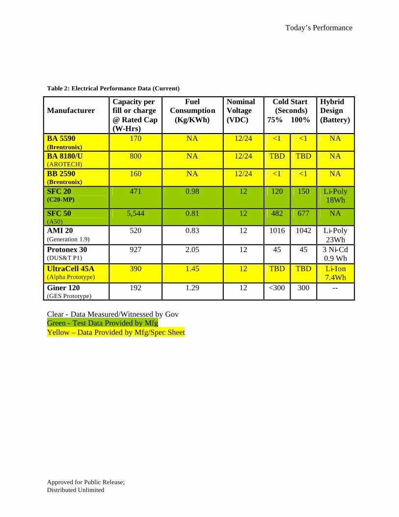
3.3 Current and Projected Performance Parameters 3.3.1 Current Performance Parameter Tables
Clear - Data Measured/Witnessed by Gov Green - Test Data Provided by Mfg Yellow – Data Provided by Mfg/Spec Sheet
Table 1: Physical Performance Data (Current) Manufacturer
Total Unit
Volume (cc)
Base Unit
Volume
(cc)
Auxiliary Unit
Volume (cc)
Wet Weight
(kg)
Dry Weight
(kg)
Auxiliary Weight
(kg)
BA 5590/U (MIL Power)
883 883 NA 1.03 1.03 NA
BA 8180/U (AROTECH)
3,913 3085 828 3.05 2.7 0.35
BB 2590/U (Bren-Tronics)
868 868 NA 1.4 1.4 NA
SFC 20 C20-MP
2,812 2,312 500 2.47 2 0.47
SFC 50 A50
19,820 14,820 5,000 10.3 6 4.30
AMI 20 Generation 1.9
4,433 3,455 978
1.79 1.29 0.50
Protonex 30 (DUS&T P1)
2,306 1,226 1,080 2.33 1.08 1.25
UltraCell 45A (Alpha Prototype)
1,770 1,270 500 1.77 1.20 0.57
Giner 120 (GES 120)
14, 287 14, 287 250 9.00 8.80 (H2O res)
0.20
Today’s Performance
Approved for Public Release; Distributed Unlimited
Table 2: Electrical Performance Data (Current)
Clear - Data Measured/Witnessed by Gov Green - Test Data Provided by Mfg Yellow – Data Provided by Mfg/Spec Sheet
Manufacturer
Capacity per fill or charge @ Rated Cap (W-Hrs)
Fuel Consumption
(Kg/KWh)
Nominal Voltage (VDC)
Cold Start (Seconds)
75% 100%
Hybrid Design (Battery)
BA 5590 (Brentronix)
170 NA 12/24 <1 <1 NA
BA 8180/U (AROTECH)
800 NA 12/24 TBD TBD NA
BB 2590 (Brentronix)
160 NA 12/24 <1 <1 NA
SFC 20 (C20-MP)
471 0.98 12 120 150 Li-Poly 18Wh
SFC 50 (A50)
5,544 0.81 12 482 677 NA
AMI 20 (Generation 1.9)
520
0.83 12 1016 1042 Li-Poly 23Wh
Protonex 30 (DUS&T P1)
927 2.05 12 45 45 3 Ni-Cd 0.9 Wh
UltraCell 45A (Alpha Prototype)
390 1.45 12 TBD TBD Li-Ion 7.4Wh
Giner 120 (GES Prototype)
192 1.29 12 <300 300 --
Today’s Performance
Approved for Public Release; Distributed Unlimited
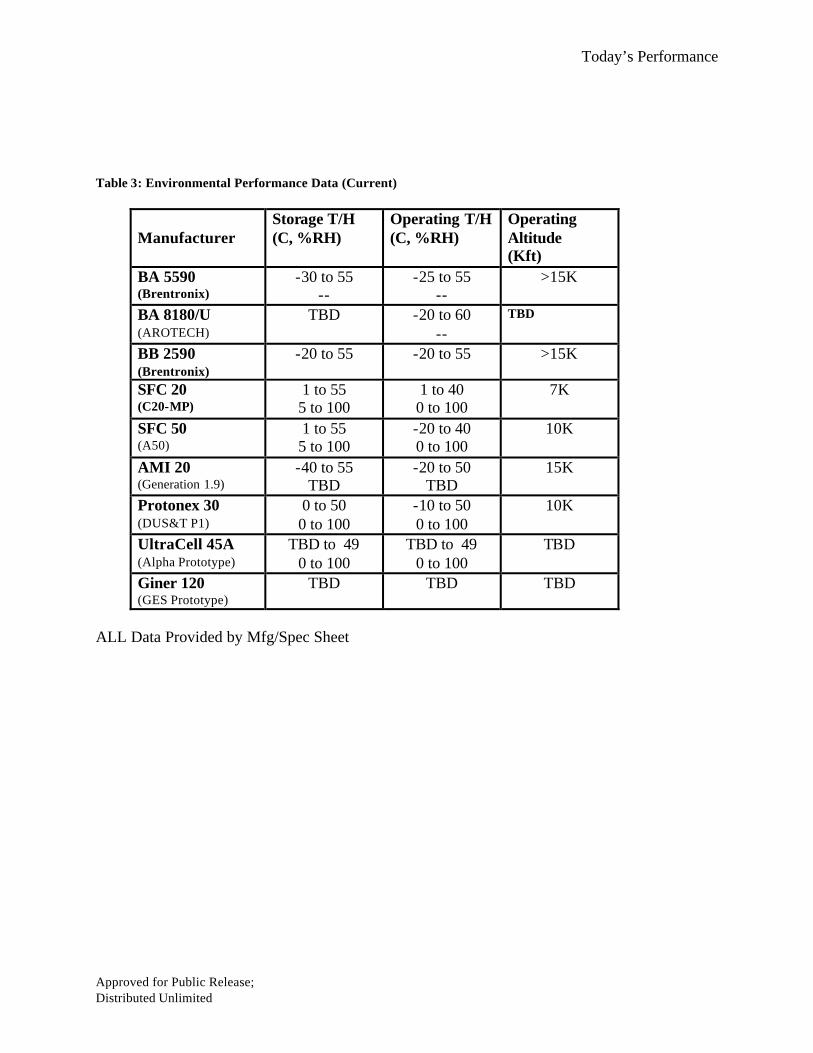
Table 3: Environmental Performance Data (Current)
Manufacturer
Storage T/H (C, %RH)
Operating T/H (C, %RH)
Operating Altitude (Kft)
BA 5590 (Brentronix)
-30 to 55 --
-25 to 55 --
>15K
BA 8180/U (AROTECH)
TBD -20 to 60 --
TBD
BB 2590 (Brentronix)
-20 to 55 -20 to 55 >15K
SFC 20 (C20-MP)
1 to 55 5 to 100
1 to 40 0 to 100
7K
SFC 50 (A50)
1 to 55 5 to 100
-20 to 40 0 to 100
10K
AMI 20 (Generation 1.9)
-40 to 55 TBD
-20 to 50 TBD
15K
Protonex 30 (DUS&T P1)
0 to 50 0 to 100
-10 to 50 0 to 100
10K
UltraCell 45A (Alpha Prototype)
TBD to 49 0 to 100
TBD to 49 0 to 100
TBD
Giner 120 (GES Prototype)
TBD TBD TBD
ALL Data Provided by Mfg/Spec Sheet
Today’s Performance
Approved for Public Release; Distributed Unlimited
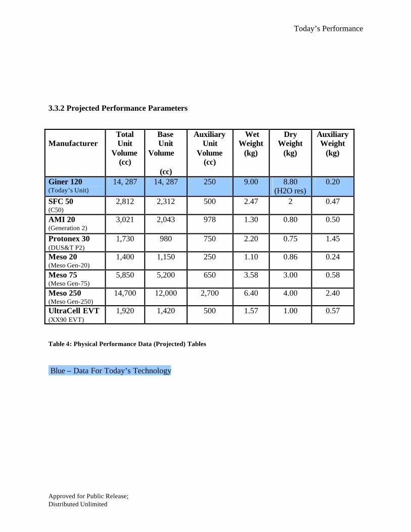
3.3.2 Projected Performance Parameters
Table 4: Physical Performance Data (Projected) Tables Blue – Data For Today’s Technology
Manufacturer
Total Unit
Volume (cc)
Base Unit
Volume
(cc)
Auxiliary Unit
Volume (cc)
Wet Weight
(kg)
Dry Weight
(kg)
Auxiliary Weight
(kg)
Giner 120 (Today’s Unit)
14, 287 14, 287 250 9.00 8.80 (H2O res)
0.20
SFC 50 (C50)
2,812 2,312 500 2.47 2 0.47
AMI 20 (Generation 2)
3,021 2,043 978 1.30 0.80 0.50
Protonex 30 (DUS&T P2)
1,730 980 750 2.20 0.75 1.45
Meso 20 (Meso Gen-20)
1,400 1,150 250 1.10 0.86 0.24
Meso 75 (Meso Gen-75)
5,850 5,200 650 3.58 3.00 0.58
Meso 250 (Meso Gen-250)
14,700 12,000 2,700 6.40 4.00 2.40
UltraCell EVT (XX90 EVT)
1,920 1,420 500 1.57 1.00 0.57

Today’s Performance
Approved for Public Release; Distributed Unlimited
Table 5: Electrical Performance Data (Projected)
Blue – Data For Today’s Technology
Manufacturer
Capacity Of One Container @ Rated Cap
(W-Hrs)
Fuel Consumption
(Kg/KWh)
Nominal Voltage (VDC)
Cold Start (Seconds)
75% 100%
Hybrid Design
(Battery)
Giner 120 (Today’s Unit)
192 1.29 12 <300 300 --
SFC 50 (C50)
480 0.98 12/24 120 150 10-100Wh
AMI 20 (Generation 2)
820 0.49 12 <900 <900 Li-Poly 23Wh
Protonex 30 (DUS&T P2)
720 2.05 12 <45 <45 3 Ni-Cd 0.9 Wh
Meso 20 (Meso Gen-20)
316 1.34 12 <600 <600 TBD
Meso 75 (Meso Gen-75)
1,530 0.48 12 <900 <900 TBD
Meso 250 (Meso Gen-250)
6,000 0.48 24 <900 <900 TBD
UltraCell 45 (XX90 EVT)
480 1.20 12 TBD TBD Li-Ion 7.4Wh
Today’s Performance
Approved for Public Release; Distributed Unlimited
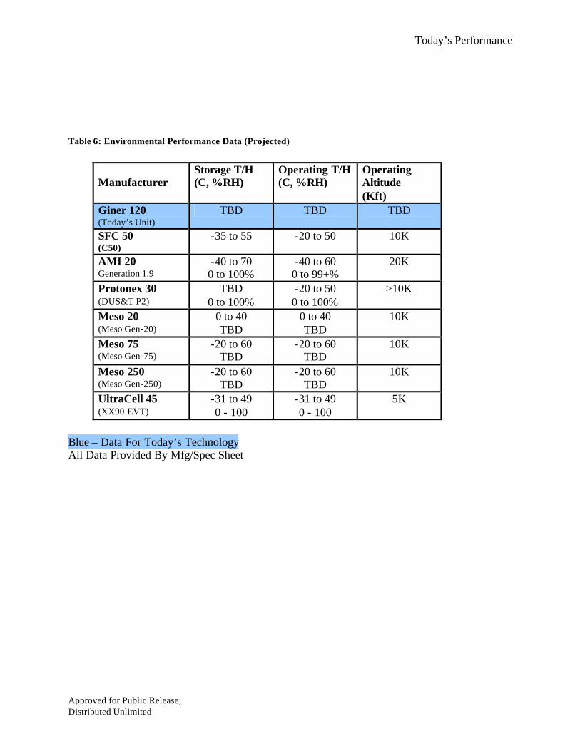
Table 6: Environmental Performance Data (Projected)
Manufacturer
Storage T/H (C, %RH)
Operating T/H (C, %RH)
Operating Altitude (Kft)
Giner 120 (Today’s Unit)
TBD TBD TBD
SFC 50 (C50)
-35 to 55 -20 to 50 10K
AMI 20 Generation 1.9
-40 to 70 0 to 100%
-40 to 60 0 to 99+%
20K
Protonex 30 (DUS&T P2)
TBD 0 to 100%
-20 to 50 0 to 100%
>10K
Meso 20 (Meso Gen-20)
0 to 40 TBD
0 to 40 TBD
10K
Meso 75 (Meso Gen-75)
-20 to 60 TBD
-20 to 60 TBD
10K
Meso 250 (Meso Gen-250)
-20 to 60 TBD
-20 to 60 TBD
10K
UltraCell 45 (XX90 EVT)
-31 to 49 0 - 100
-31 to 49 0 - 100
5K
Blue – Data For Today’s Technology All Data Provided By Mfg/Spec Sheet
Today’s Performance
Approved for Public Release; Distributed Unlimited
3.4 Technology Pro’s and Con’s
3.4.1 General In examining the various different man portable technologies, some basic observations can be made. No system is known to have adequate signature reduction for all missions. The exhaust temperature of fuel cells seen here exhaust at temperatures up to 65ºC, with solid oxides technologies generating the highest maximum temperatures do to their high operating stack temperature. Fuel efficiency determines the net heat output. 3.4.2 Radiated Noise The audible range of fuel cells seen here are roughly 32dba to 65dba. The noise is primarily generated by the internal the pumps, fans, blowers, etc. This is a common issue among fuel cell technologies using small balance of plant components. These components are available in generic form, but can be expected to be noisy and power-hungry. Some companies resort to internal development and results in a formidable task. 3.4.3 Orientation Orientation sensitivity will also be an issue with certain fuel cell technologies and designs. Many technologies are orientation independent. The orientation range seen here was +/- 30 Deg to +/- 45 Deg of the upright/standard position Pressurized gas fuels are inherently less sensitive to orientation. 3.4.4 Hybridization All of the fuel cell systems can have various levels of battery hybridization that will affect the performance capabilities. However, the level of hybridization and type of battery used will influence the weight and volume of the system. The trade off for a larger battery means increased weight and volume. Most systems have and/or plan to add a small, high-power rechargeable battery parallel to the system output for power during startup time and pulse handling capability. 3.4.5 Cold Start The cold start time range for the fuel cells evaluated ranged from 0 to 15 minutes. As expected the solid oxides takes the longest time to provide the required load. This is due to the high stack temperatures that must be reached for operation and their narrow temperature window for reliable operation. Hybridizing the systems with a battery allows the user to get instant power at the appropriate level until the stack can provide power but adds to the system’s weight. 3.4.6 Fuel Logistics The logistics of fuel is an important issue to be addressed before the systems can begin transitioning into the field. The ability to package a fuel into a cartridges could allow the fuel to be viewed as a commodity. This can be seen for small DMFCs and hydride (sodium borohydride) fuel options. Large containers can potentially allow for faster, easier and more accessible bulk refueling options like gas cans, but raises a risk in improper fuel type and mixing that would have to be addressed in labels, training and/or other methods. The small cartridges may be easier to deal with as a commodity, but the large containers for filling would be more efficient and provide lighter/smaller packages for extended missions.

Today’s Performance
Approved for Public Release; Distributed Unlimited
4. Analysis and Projection Plots
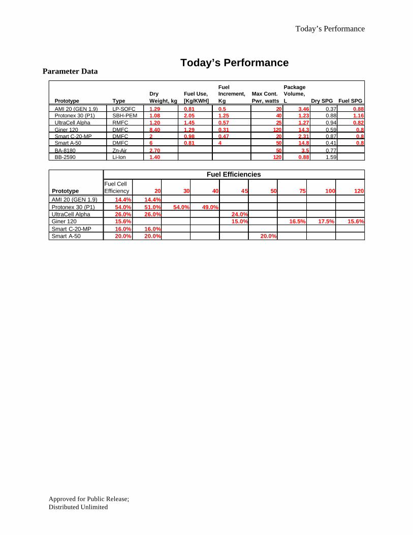
The data collected from the different tests and the system performance specifications obtained were used to plot potential operational graphs. The graphs provide potential current and projected operational trends over different required power levels and time durations. The BA-5590 is plotted appropriately for comparison to the various fuel cell systems. Plots and projections are intended to give different perspectives relevant to the potential use of these technologies. There are four types of plots, a Simple Direct-Use Plot, a Simple Charger Plot, a Charger Scenario Plot and a Direct-Use Scenario Plot. 4.1 Current Performance Plots 4.1.1 Simple Direct-Use Plots The simple direct-use plot shows the weight (kg) vs. amp-hour relationship of each power source. Also plotted is the volume (liters) vs. amp-hour relationship of each power system. The plots assume that the fuel cell system would directly be used in an abstract application, no battery charging is considered and fuel is incremented as a cartridge to the specified size. The application would utilize exactly 100% of the rated full power of the power source continually. In this way power and time considerations can be neglected, indicating a best-case system weight. The weight includes the fuel cell and fuel for steady-state operation and does not take into account fuel used during start up. The volume is the total volume of the fuel cell system and fuel cartridges required to provide the amp-hr requested. The graphs and the corresponding tables are located in Appendix A. 4.1.2 Simple Charger Plot The simple charger plots show the total weight (kg) vs. amp-hour performance of each power source. Also plotted is the total volume (liters) vs. amp-hour relationship of each power system. The plot assumes that the fuel cell system would directly be used as a battery charger. The batteries are used to provide power to an abstract application. The plot assumes that one fuel cell system would maintain two BB-2590s, one being charged and one being used at any given time. For every 75-watt increment of the fuel cell system’s full power an additional two batteries are added. For example, a 25-watt system would maintain 2 batteries, while a 120-watt system would maintain 4 batteries. The total weight includes the fuel cell, the fuel for steady-state operation and all of the BB-2590s used. The volume is the total volume of the fuel cell system, fuel cartridges, and all of the BB-2590s used. The plots do not take into account fuel used during start up. It is assumed that the charge efficiency for each system is 69%. This is assuming 85% battery efficiency, 90% charge circuit efficiency, and a 90% power utilization efficiency. Power utilization is an approximate method of representing that not all of the fuel cell power will be made available for charging due to the current and voltage limits associated with charging batteries. The graphs and the corresponding tables are located in Appendix A. 4.1.3 Charger Scenario Plot

Today’s Performance
Approved for Public Release; Distributed Unlimited
The charger scenario plots show the system weight (kg) vs. mission time and total capacity at a specific power and equipment battery slot use for each power source. It is assumed that the fuel cell system would directly be used as a battery charger. Because the BB-2590 has more than double the power output that the BA-5590, and some applications require multiple BA-5590’s to provide enough current without blowing a fuse, the charger scenarios, where reasonable, use less BB-2590’s than would have been needed with BA-5590’s. This difference is indicated by a difference in slot counts. A consequence of this will be more-frequent changeover on the rechargeable batteries, but will minimize the “dead-weight” while permitting sustainable operations. The power levels chosen for the scenarios are 12 watts, 20 watts, 40 watts, 80 watts, and 135 watts. Each power range generically represents either a type of equipment or a suite of equipment. The 12-watt could represent a radio, the 20-watt a small laptop, and the 40-watts an AN/PRC-117 or similar radio.
The plot uses two BB-2590’s for every BA-5590 needed to operate the equipment. The BB-2590’s will form a pool in which batteries will rotate between equipment based upon their individual power draws, but the charger set’s average power is sufficient to maintain the rotation from discharge to charge plus the charger inefficiency for continuous sustainability, such that for every battery in use, exactly one is being charged. At any given time, this assumption will provide the minimum number of charged batteries for this generic load profile. All batteries will start the mission fully charged, slightly reducing the total fuel needed. Battery charging is allowed the same quantity of time as is needed for discharge. Batteries are charged as soon as they complete a discharge. Fuel cell-chargers are added incrementally until the total system power (including charging loss) can be sustained by the fuel cell(s). A major and presently unrealistic assumption is that the chargers must be able to utilize their share of the power demand at all times and be able to dump this power into the batteries continuously. The standard continuous voltage charge and continuous voltage output from these fuel cells will NOT do this. Special charge controllers, DC-DC convertors and some form of power management for larger units must be incorporated to charge at constant-power output for optimal use of fuel cells. The graphs and the corresponding tables are located in Appendix A.
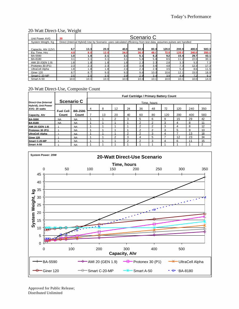
4.1.4 Direct-Use Scenario Plot The direct-use scenario plots graphs the system weight (kg) vs. mission time performance at a specific power level for each power source. These plots assume that the fuel cell systems will be used as direct power sources for the specific scenarios. The power levels and general equipment used in these plots are the same used for the charger scenario plots in section 4.3; 12 watts, 20 watts, 40 watts, 80 watts, and 135 watts. The fuel cell system will provide the required load at the various levels continuously. If the efficiency data for a fuel cell at a specific level was not obtained, the full load capacity efficiency was used. Cartridges are added to the total weight as the mission time is increased. The weight includes the fuel cell and fuel for steady-state operation and does not take into account fuel used during start up. 5. Conclusions 5.1 Volumetric and Gravimetric Savings
Today’s Performance
Approved for Public Release; Distributed Unlimited
The analysis and observations identified specific points reguarding fuel cells and their potential roles for man packable power. The analysis shows that a significant volumetric and gravimetric savings are potential over time when compared to the current BA-5590 battery technology. This is even true when utilizing the fuel cells as battery chargers and accounting for the charge efficiencies and number of batteries charged. Speculations can be made in comparison of technologies and where they crossover during time on the plots, HOWEVER, caution must be taken as all systems need further improvements in reliability, durability, ruggedization and specific operational environment capabilities to make these military units. 5.2 Operational Life Limitations
The analysis provided in this paper does not accurately reflect the fuel cell’s demonstrated life. In some cases the data projected for 240 hours of operation is projected for a longer durration than the fuel cell has been demonstrated to operate. This shortfall will be rectified when the system have demonstrated extended operational life. 5.3 Actual Test Data
The analysis provided is also limited by the fact that all systems projected were not actually demonstrated and/or tested at a Government facility and at various power levels. Efficiencies at the specific power levels were estimated by the manufacturers or interpolated/extrapolated based on data provided. Actual data at the specific power levels will provide the data required to make the projections more accurate. 5.4 Hybridization
Currently the fuel cell technologies have reached a point in time where they need user
feedback for hybridization. Hybridization is required for pulse capability and will to an extent improve system efficiencies that have regular pulses, but the battery required adds to the unit weight/volume. Guidance is required for manufacturers to optimize weight and volume against operational requirements. 5.5 Fuel Logistic Support
Many of the manufacturers assessed for this effort believe the fuel will be supplied as a commodity. Existing designs seem to have migrated toward a simple closed container with a fuel line that implies bulk refueling from “gas can” to system “tank”. Transporting and handling of the various fuels as commodities require qualification and approval through DoD as well as DOT. In addition, many commodities (unique to each manufacturer) may be required. An alternative solution may be to ship the fuels in slightly larger (gallon units) bulk canisters for refill operations in the field.

Today’s Performance
Approved for Public Release; Distributed Unlimited
Appendix A
Current Performance Plots
Today’s Performance
Approved for Public Release; Distributed Unlimited
Today’s Performance
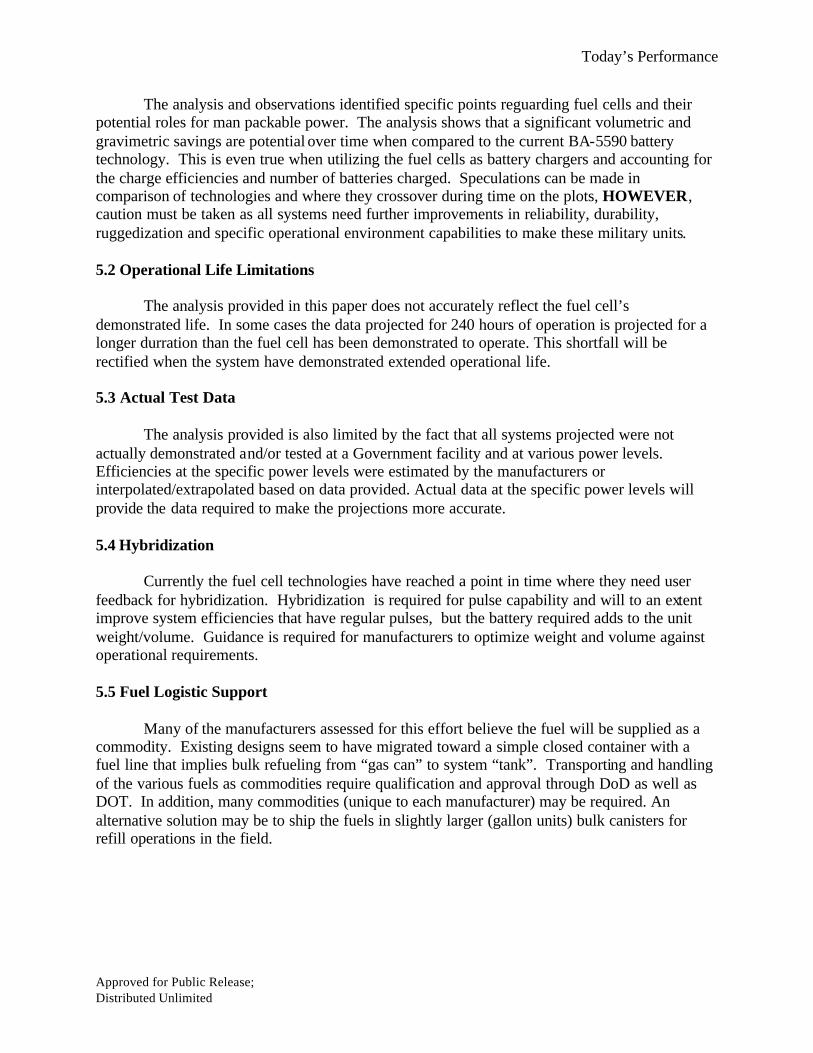
AMI 20 (GEN 1.9) LP-SOFC 1.29 0.81 0.5 20 3.46 0.37 0.88Protonex 30 (P1) SBH-PEM 1.08 2.05 1.25 40 1.23 0.88 1.16UltraCell Alpha RMFC 1.20 1.45 0.57 25 1.27 0.94 0.82Giner 120 DMFC 8.40 1.29 0.31 120 14.3 0.59 0.8Smart C-20-MP DMFC 2 0.98 0.47 20 2.31 0.87 0.8Smart A-50 DMFC 6 0.81 4 50 14.8 0.41 0.8BA-8180 Zn-Air 2.70 50 3.5 0.77BB-2590 Li-Ion 1.40 120 0.88 1.59
Max Cont. Pwr, watts
Fuel Increment, Kg Fuel SPGDry SPG
Package Volume, LPrototype Type
Dry Weight, kg
Fuel Use, [Kg/KWH]
Fuel Cell Efficiency 20 30 40 45 50 75 100 120
AMI 20 (GEN 1.9) 14.4% 14.4%Protonex 30 (P1) 54.0% 51.0% 54.0% 49.0%UltraCell Alpha 26.0% 26.0% 24.0%Giner 120 15.6% 15.0% 16.5% 17.5% 15.6%Smart C-20-MP 16.0% 16.0%Smart A-50 20.0% 20.0% 20.0%
Fuel Efficiencies
Prototype
Parameter Data

Today’s Performance
Approved for Public Release; Distributed Unlimited
Simple Direct-UseWeight, KgCapacity, Ahr (12V) 14.0 28.0 42.0 70.0 140.0 210.0 280.0 420.0 560.0 700.0BA-5590 1.0 2.1 3.1 5.1 10.3 15.4 20.5 30.8 41.0 51.3BA-8180 3.1 3.1 3.1 5.8 8.5 11.2 13.9 22.0 27.4 35.5AMI 20 (GEN 1.9) 1.8 1.8 1.8 2.3 2.8 3.8 4.3 5.8 7.3 8.8Protonex 30 (P1) 2.3 2.3 2.3 3.6 4.8 7.3 8.6 12.3 16.1 19.8UltraCell Alpha 1.8 1.8 2.3 2.9 4.1 5.2 6.3 9.2 11.5 14.3Giner 120 8.7 9.0 9.3 9.6 10.9 11.8 13.1 15.2 17.7 19.9Smart C-20-MP 2.5 2.5 2.9 2.9 3.9 4.8 5.8 7.2 9.1 10.9Smart A-50 10.0 10.0 10.0 10.0 10.0 10.0 10.0 14.0 14.0 14.0
Use As-Is, no charging, no power/time considerations
Simple, Direct-Use, Weight
0
5
10
15
20
25
30
35
40
45
50
0 100 200 300 400 500 600 700Amp-Hours
Wei
gh
t, K
g
BA-5590 AMI 20 (GEN 1.9) Protonex 30 (P1) UltraCell Alpha
Giner 120 Smart C-20-MP Smart A-50 BA-8180
Simple Direct-UseVolume, LitersCapacity, Ahr (12V) 14.0 28.0 42.0 70.0 140.0 210.0 280.0 420.0 560.0 700.0BA-5590 0.9 1.8 2.7 4.4 8.8 13.3 17.7 26.5 35.3 44.2BA-8180 4.4 4.4 4.4 7.9 11.4 14.9 18.4 28.9 35.9 46.4AMI 20 (GEN 1.9) 4.0 4.0 4.0 4.6 5.2 5.7 6.3 8.0 9.1 10.8Protonex 30 (P1) 2.3 2.3 2.3 3.4 4.5 5.5 6.6 9.9 12.0 15.2UltraCell Alpha 2.0 2.0 2.7 2.7 4.1 5.4 6.8 9.6 12.4 15.2Giner 120 14.7 15.1 15.1 15.9 17.0 18.2 19.3 21.7 24.4 26.7Smart C-20-MP 2.9 2.9 2.9 3.5 4.7 5.2 6.4 8.2 9.9 11.7Smart A-50 19.8 19.8 19.8 19.8 19.8 19.8 19.8 19.8 24.8 24.8
Use As-Is, no charging, no power/time considerations
Simple, Direct-Use, Volume
0
5
10
15
20
25
30
35
40
45
50
0 100 200 300 400 500 600 700Amp-Hours
To
tal V
olu
me,
Lit
ers
BA-5590 AMI 20 (GEN 1.9) Protonex 30 (P1) UltraCell Alpha
Giner 120 Smart C-20-MP Smart A-50 BA-8180
Today’s Performance
Approved for Public Release; Distributed Unlimited
Simple ChargerWeight, KgCapacity, Ahr (12V) 14.0 28.0 42.0 70.0 140.0 210.0 280.0 420.0 560.0 700.0BA-5590 1.0 2.1 3.1 5.1 10.3 15.4 20.5 30.8 41.0 51.3BA-8180 5.5 5.5 5.5 8.2 10.9 16.3 19.0 27.1 35.2 43.3AMI 20 (GEN 1.9) 4.1 4.6 4.6 5.1 6.1 7.1 8.1 10.1 12.1 14.1Protonex 30 (P1) 3.9 5.1 5.1 6.4 8.9 11.4 13.9 18.9 23.9 30.1UltraCell Alpha 4.0 4.6 4.6 5.7 7.4 9.1 10.8 14.8 18.3 22.2Giner 120 14.0 14.0 14.0 14.6 16.5 18.0 19.6 23.0 26.1 29.5Smart C-20-MP 4.8 5.3 5.3 5.7 7.2 8.6 9.5 11.9 14.7 17.0Smart A-50 8.8 12.8 12.8 12.8 12.8 12.8 12.8 16.8 16.8 20.8
Use with x2 BB-2590's per each 75-watts, rounded up, no consideration for time/power, 69% charge efficiency
Simple, Charger, Weight
0
5
10
15
20
25
30
35
40
45
50
0 100 200 300 400 500 600 700Capacity, Ahr
To
tal W
eig
ht,
Kg
BA-5590 AMI 20 (GEN 1.9) Protonex 30 (P1) UltraCell Alpha
Giner 120 Smart C-20-MP Smart A-50 BA-8180
Simple ChargerVolume, LitersCapacity, Ahr (12V) 14.0 28.0 42.0 70.0 140.0 210.0 280.0 420.0 560.0 700.0BA-5590 0.9 1.8 2.7 4.4 8.8 13.3 17.7 26.5 35.3 44.2BA-8180 5.3 5.3 5.3 8.8 12.3 19.3 22.8 33.3 43.8 54.3AMI 20 (GEN 1.9) 5.2 5.8 5.8 6.4 6.9 8.1 9.2 10.9 13.2 15.4Protonex 30 (P1) 3.0 4.1 4.1 5.1 6.2 8.4 10.5 14.8 18.1 22.4UltraCell Alpha 3.0 3.7 3.7 4.4 6.5 8.6 10.7 14.2 18.3 21.8Giner 120 17.8 17.8 17.8 18.6 20.1 22.1 23.6 27.1 30.6 34.5Smart C-20-MP 4.1 4.7 4.7 5.2 6.4 7.6 9.4 11.7 14.6 17.0Smart A-50 16.6 21.6 21.6 21.6 21.6 21.6 21.6 26.6 26.6 31.6
Use with x2 BB-2590's per each 75-watts, rounded up, no consideration for time/power, 69% charge efficiency
Simple, Charger, Volume
0
10
20
30
40
50
60
0 100 200 300 400 500 600 700Capacity, Ahr
To
tal V
olu
me,
Lit
ers
BA-5590 AMI 20 (GEN 1.9) Protonex 30 (P1) UltraCell Alpha
Giner 120 Smart C-20-MP Smart A-50 BA-8180

Today’s Performance
Approved for Public Release; Distributed Unlimited
135-Watt Charger, Weight Mission Power AVG 1355590 Slot Count 82590 Slot Count 5Per-battery power: 17Charge efficiency: 69%
System Weight, KgCapacity, Ahr (12V) 45.0 90.0 135.0 180.0 270.0 405.0 540.0 675.0 810.0 1350.0Eq. Time, Hrs 4.0 8.0 12.0 16.0 24.0 36.0 48.0 60.0 72.0 120.0BA-5590 8.2 8.2 16.4 16.4 24.6 32.8 41.0 57.4 65.6 106.6BA-8180 24.8 24.8 24.8 24.8 24.8 32.9 41.0 49.1 57.2 89.6AMI 20 (GEN 1.9) 26.9 26.9 31.9 31.9 31.9 31.9 36.9 36.9 36.9 46.9Protonex 30 (P1) 19.4 19.4 25.7 25.7 25.7 31.9 38.2 44.4 50.7 69.4UltraCell Alpha 23.6 23.6 28.2 28.2 28.2 32.7 37.3 41.8 41.8 55.5Giner 120 30.8 30.8 31.4 32.7 34.5 37.6 40.7 43.8 46.9 59.3Smart C-20-MP 34.0 34.0 38.7 38.7 38.7 43.4 43.4 48.1 48.1 57.5Smart A-50 38.0 38.0 54.0 54.0 54.0 54.0 54.0 54.0 54.0 70.0
Use with x2 BB-2590's per each "Operational Battery", fuel cartridges are incremented, rechargeable batteries start fully-charged
Scenario Ashall not exceed 45-wattsbattery charge efficiency * charger efficiency * charger utilization
135-Watt Charger, Composite Count
4 8 12 16 24 36 48 60 72 120
Capacity, Ahr 45 90 135 180 270 405 540 675 810 1350
BA-5590 NA NA 5 10 10 15 20 30 40 50 60 100BA-8180 NA 10 4 4 4 4 4 7 10 13 16 28AMI 20 (GEN 1.9) 10 10 0 0 10 10 10 10 20 20 20 40Protonex 30 (P1) 5 10 0 0 5 5 5 10 15 20 25 40UltraCell Alpha 8 10 0 0 8 8 8 16 24 32 32 56Giner 120 2 10 0 0 2 6 12 22 32 42 52 92Smart C-20-MP 10 10 0 0 10 10 10 20 20 30 30 50Smart A-50 4 10 0 0 4 4 4 4 4 4 4 8
Time, hours
Fuel Cartridge / Primary Battery CountMission Power AVG: 1355590 Slot Count: 82590 Slot Count: 5Charge efficiency: 0.69
Scenario A
BB-2590 Count
Fuel Cell Count
135-Watt Charger Scenario
0
10
20
30
40
50
60
70
80
90
100
0 200 400 600 800 1000 1200Capacity, Ahr
Sys
tem
Wei
gh
t, k
g
0 20 40 60 80 100 120
Mission Time, Hours
BA-5590 AMI 20 (GEN 1.9) Protonex 30 (P1) UltraCell Alpha
Giner 120 Smart C-20-MP Smart A-50 BA-8180
System Power: 135W5590 Slot Count: 82590 Slot Count: 5Charger Efficiency: 69%

Today’s Performance
Approved for Public Release; Distributed Unlimited
80-Watt Charger, Weight Mission Power AVG 805590 Slot Count 42590 Slot Count 2Per-battery power: 20Charge efficiency: 69%
System Weight, KgCapacity, Ahr (12V) 26.7 53.3 80.0 106.7 160.0 240.0 320.0 400.0 480.0 800.0Eq. Time, Hrs 4.0 8.0 12.0 16.0 24.0 36.0 48.0 60.0 72.0 120.0BA-5590 4.1 4.1 8.2 8.2 12.3 20.5 24.6 32.8 36.9 61.5BA-8180 11.0 11.0 11.0 11.0 13.7 19.1 24.5 27.2 32.6 51.5AMI 20 (GEN 1.9) 13.3 16.3 16.3 16.3 16.3 16.3 19.3 19.3 22.3 25.3Protonex 30 (P1) 8.8 12.6 12.6 12.6 16.3 16.3 20.1 23.8 27.6 38.8UltraCell Alpha 11.6 14.5 14.5 14.5 17.3 17.3 20.2 23.0 23.0 31.6Giner 120 14.0 14.3 14.9 15.6 16.8 18.7 20.5 22.4 23.9 31.4Smart C-20-MP 17.6 20.4 20.4 20.4 20.4 23.2 23.2 26.1 26.1 31.7Smart A-50 23.6 35.6 35.6 35.6 35.6 35.6 35.6 35.6 35.6 35.6
Use with x2 BB-2590's per each "Operational Battery", fuel cartridges are incremented, rechargeable batteries start fully-charged
Scenario Ashall not exceed 45-wattsbattery charge efficiency * charger efficiency * charger utilization
80-Watt Charger, Composite Count
4 8 12 16 24 36 48 60 72 120
Capacity, Ahr 27 53 80 107 160 240 320 400 480 800
BA-5590 NA NA 2 4 6 8 12 18 24 30 36 58BA-8180 NA 4 2 2 2 2 3 5 7 8 10 17AMI 20 (GEN 1.9) 6 4 0 6 6 6 6 6 12 12 18 24Protonex 30 (P1) 3 4 0 3 3 3 6 6 9 12 15 24UltraCell Alpha 5 4 0 5 5 5 10 10 15 20 20 35Giner 120 1 4 0 1 3 5 9 15 21 27 32 56Smart C-20-MP 6 4 0 6 6 6 6 12 12 18 18 30Smart A-50 3 4 0 3 3 3 3 3 3 3 3 3
Time, hours
Fuel Cartridge / Primary Battery CountMission Power AVG: 805590 Slot Count: 42590 Slot Count: 2Charge efficiency: 0.69
Scenario A
BB-2590 Count
Fuel Cell Count
80-Watt Charger Scenario
0
10
20
30
40
50
60
0 100 200 300 400 500 600 700 800Capacity, Ahr
Sys
tem
Wei
ght,
kg
0 20 40 60 80 100 120
Mission Time, Hours
BA-5590 AMI 20 (GEN 1.9) Protonex 30 (P1) UltraCell Alpha
Giner 120 Smart C-20-MP Smart A-50 BA-8180
System Power: 80W5590 Slot Count: 42590 Slot Count: 2Charger Efficiency: 69%

Today’s Performance
Approved for Public Release; Distributed Unlimited
40-Watt Charger, Weight Mission Power AVG 405590 Slot Count 22590 Slot Count 1Per-battery power: 20Charge efficiency: 69%
System Weight, KgCapacity, Ahr (12V) 13.3 26.7 40.0 53.3 80.0 120.0 160.0 240.0 400.0 800.0Eq. Time, Hrs 4.0 8.0 12.0 16.0 24.0 36.0 48.0 72.0 120.0 240.0BA-5590 2.1 2.1 4.1 4.1 6.2 10.3 12.3 18.5 30.8 59.5BA-8180 5.5 5.5 5.5 5.5 8.2 10.9 13.6 16.3 27.1 51.4AMI 20 (GEN 1.9) 6.7 8.2 8.2 8.2 8.2 8.2 9.7 11.2 12.7 18.7Protonex 30 (P1) 5.0 7.5 7.5 7.5 7.5 10.0 12.5 15.0 20.0 35.0UltraCell Alpha 6.4 8.1 8.1 8.1 8.1 9.8 11.5 13.2 16.7 26.9Giner 120 11.2 11.5 11.8 12.1 12.8 13.7 14.6 16.5 20.5 30.1Smart C-20-MP 8.8 10.2 10.2 10.2 10.2 11.6 11.6 13.0 15.9 22.9Smart A-50 14.8 22.8 22.8 22.8 22.8 22.8 22.8 22.8 22.8 30.8
Use with x2 BB-2590's per each "Operational Battery", fuel cartridges are incremented, rechargeable batteries start fully-charged
Scenario Ashall not exceed 45-wattsbattery charge efficiency * charger efficiency * charger utilization
40-Watt Charger, Composite Count
4 8 12 16 24 36 48 72 120 240
Capacity, Ahr 13 27 40 53 80 120 160 240 400 800
BA-5590 NA NA 1 2 3 4 6 9 12 18 29 58BA-8180 NA 2 1 1 1 1 2 3 4 5 9 18AMI 20 (GEN 1.9) 3 2 0 3 3 3 3 3 6 9 12 24Protonex 30 (P1) 2 2 0 2 2 2 2 4 6 8 12 24UltraCell Alpha 3 2 0 3 3 3 3 6 9 12 18 36Giner 120 1 2 0 1 2 3 5 8 11 17 30 61Smart C-20-MP 3 2 0 3 3 3 3 6 6 9 15 30Smart A-50 2 2 0 2 2 2 2 2 2 2 2 4
Time, hours
Fuel Cartridge / Primary Battery CountMission Power AVG: 405590 Slot Count: 22590 Slot Count: 1Charge efficiency: 0.69
Scenario A
BB-2590 Count
Fuel Cell Count
40-Watt Charger Scenario
0
10
20
30
40
50
60
0 100 200 300 400 500 600 700 800Capacity, Ahr
Sys
tem
Wei
ght,
kg
0 50 100 150 200
Mission Time, Hours
BA-5590 AMI 20 (GEN 1.9) Protonex 30 (P1) UltraCell Alpha
Giner 120 Smart C-20-MP Smart A-50 BA-8180
System Power: 40W5590 Slot Count: 22590 Slot Count: 1Charger Efficiency: 69%

Today’s Performance
Approved for Public Release; Distributed Unlimited
20-Watt Charger, Weight Mission Power AVG 205590 Slot Count 12590 Slot Count 1Per-battery power: 20Charge efficiency: 69%
System Weight, KgCapacity, Ahr (12V) 6.7 13.3 20.0 40.0 60.0 80.0 120.0 200.0 400.0 583.3Eq. Time, Hrs 4.0 8.0 12.0 24.0 36.0 48.0 72.0 120.0 240.0 350.0BA-5590 1.0 1.0 2.1 3.1 5.1 6.2 9.2 15.4 29.7 43.1BA-8180 5.5 5.5 5.5 5.5 5.5 8.2 10.9 13.6 27.1 37.9AMI 20 (GEN 1.9) 5.4 5.4 5.4 6.4 6.4 6.4 7.4 8.4 11.4 14.4Protonex 30 (P1) 3.9 3.9 3.9 5.1 6.4 6.4 7.6 11.4 18.9 26.4UltraCell Alpha 5.2 5.2 5.2 6.3 6.3 7.5 8.6 9.8 15.5 20.0Giner 120 11.2 11.2 11.2 11.8 12.4 12.8 14.0 15.9 21.1 25.8Smart C-20-MP 6.8 6.8 6.8 7.7 7.7 8.7 8.7 10.6 13.4 17.1Smart A-50 8.8 8.8 8.8 12.8 12.8 12.8 12.8 12.8 16.8 16.8
Use with x2 BB-2590's per each "Operational Battery", fuel cartridges are incremented, rechargeable batteries start fully-charged
Scenario Ashall not exceed 45-wattsbattery charge efficiency * charger efficiency * charger utilization
20-Watt Charger, Composite Count
4 8 12 24 36 48 72 120 240 350
Capacity, Ahr 7 13 20 40 60 80 120 200 400 583
BA-5590 NA NA 1 1 2 3 5 6 9 15 29 42BA-8180 NA 2 1 1 1 1 1 2 3 4 9 13AMI 20 (GEN 1.9) 2 2 0 0 0 2 2 2 4 6 12 18Protonex 30 (P1) 1 2 0 0 0 1 2 2 3 6 12 18UltraCell Alpha 2 2 0 0 0 2 2 4 6 8 18 26Giner 120 1 2 0 0 0 2 4 5 9 15 32 47Smart C-20-MP 2 2 0 0 0 2 2 4 4 8 14 22Smart A-50 1 2 0 0 0 1 1 1 1 1 2 2
Time, hours
Fuel Cartridge / Primary Battery CountMission Power AVG: 205590 Slot Count: 12590 Slot Count: 1Charge efficiency: 0.69
Scenario A
BB-2590 Count
Fuel Cell Count
20-Watt Charger Scenario
0
5
10
15
20
25
30
35
40
45
50
0 100 200 300 400 500Capacity, Ahr
Sys
tem
Wei
ght,
kg
0 50 100 150 200 250 300 350
Mission Time, Hours
BA-5590 AMI 20 (GEN 1.9) Protonex 30 (P1) UltraCell Alpha
Giner 120 Smart C-20-MP Smart A-50 BA-8180
System Power: 20W5590 Slot Count: 12590 Slot Count: 1Charger Efficiency: 69%

Today’s Performance
Approved for Public Release; Distributed Unlimited
12-Watt Charger, Weight Mission Power AVG 125590 Slot Count 12590 Slot Count 1Per-battery power: 12Charge efficiency: 69%
System Weight, KgCapacity, Ahr (12V) 4.0 8.0 12.0 24.0 36.0 72.0 120.0 240.0 350.0 700.0Eq. Time, Hrs 4.0 8.0 12.0 24.0 36.0 72.0 120.0 240.0 350.0 700.0BA-5590 1.0 1.0 1.0 2.1 3.1 6.2 9.2 18.5 25.6 51.3BA-8180 5.5 5.5 5.5 5.5 5.5 8.2 10.9 16.3 24.4 43.3AMI 20 (GEN 1.9) 4.1 4.1 4.1 4.6 4.6 5.1 5.6 7.6 9.1 14.1Protonex 30 (P1) 3.9 3.9 3.9 5.1 5.1 6.4 7.6 12.6 16.4 30.1UltraCell Alpha 4.0 4.0 4.0 4.6 4.6 5.7 6.9 9.7 12.6 21.7Giner 120 11.2 11.2 11.2 11.5 11.5 12.4 13.7 16.2 18.6 26.7Smart C-20-MP 4.8 4.8 4.8 5.3 5.3 5.7 6.7 8.6 10.9 16.6Smart A-50 8.8 8.8 8.8 12.8 12.8 12.8 12.8 12.8 16.8 20.8
Use with x2 BB-2590's per each "Operational Battery", fuel cartridges are incremented, rechargeable batteries start fully-charged
Scenario Ashall not exceed 45-wattsbattery charge efficiency * charger efficiency * charger utilization
12-Watt Charger, Composite Count
4 8 12 24 36 72 120 240 350 700
Capacity, Ahr 4 8 12 24 36 72 120 240 350 700
BA-5590 NA NA 1 1 1 2 3 6 9 18 25 50BA-8180 NA 2 1 1 1 1 1 2 3 5 8 15AMI 20 (GEN 1.9) 1 2 0 0 0 1 1 2 3 7 10 20Protonex 30 (P1) 1 2 0 0 0 1 1 2 3 7 10 21UltraCell Alpha 1 2 0 0 0 1 1 3 5 10 15 31Giner 120 1 2 0 0 0 1 1 4 8 16 24 50Smart C-20-MP 1 2 0 0 0 1 1 2 4 8 13 25Smart A-50 1 2 0 0 0 1 1 1 1 1 2 3
Time, hours
Fuel Cartridge / Primary Battery CountMission Power AVG: 125590 Slot Count: 12590 Slot Count: 1Charge efficiency: 0.69
Scenario A
BB-2590 Count
Fuel Cell Count
12-Watt Charger Scenario
0
5
10
15
20
25
30
35
40
45
50
0 100 200 300 400 500 600 700Capacity, Ahr
Sys
tem
Wei
ght,
kg
0 100 200 300 400 500 600 700
Mission Time, Hours
BA-5590 AMI 20 (GEN 1.9) Protonex 30 (P1) UltraCell Alpha
Giner 120 Smart C-20-MP Smart A-50 BA-8180
System Power: 12W5590 Slot Count: 12590 Slot Count: 1Charger Efficiency: 69%

Today’s Performance
Approved for Public Release; Distributed Unlimited
12-Watt Direct-Use, Weight
System Weight, Kg
Capacity, Ahr (12V) 4.0 8.0 12.0 24.0 36.0 72.0 120.0 240.0 350.0 700.0Eq. Time, Hrs 4.0 8.0 12.0 24.0 36.0 72.0 120.0 240.0 350.0 700.0BA-5590 1.0 1.0 1.0 2.1 3.1 6.2 9.2 18.5 25.6 51.3BA-8180 3.1 3.1 3.1 3.1 3.1 5.8 8.5 13.9 19.3 35.5AMI 20 (GEN 1.9) 1.8 1.8 1.8 1.8 1.8 2.3 2.8 3.8 4.8 8.3Protonex 30 (P1) 2.3 2.3 2.3 2.3 2.3 3.6 4.8 7.3 11.1 19.8UltraCell Alpha 1.8 1.8 1.8 1.8 2.3 2.9 3.5 5.8 7.5 13.7Giner 120 8.7 8.7 8.7 9.0 9.0 9.6 10.3 12.1 14.0 19.3Smart C-20-MP 2.5 2.5 2.5 2.5 2.5 2.9 3.9 5.3 6.2 10.5Smart A-50 10.0 10.0 10.0 10.0 10.0 10.0 10.0 10.0 10.0 14.0
Direct (Internal Hybrid) Use by Scenario: uses calculated efficiency from test data, assumes pulses are handled12Unit Power AVG Scenario C
12-Watt Direct-Use, Composite Count
4 8 12 24 36 72 120 240 350 700
Capacity, Ahr 4 8 12 24 36 72 120 240 350 700BA-5590 NA NA 1 1 1 2 3 6 9 18 25 50BA-8180 NA NA 1 1 1 1 1 2 3 5 7 13AMI 20 (GEN 1.9) 1 NA 1 1 1 1 1 2 3 5 7 14Protonex 30 (P1) 1 NA 1 1 1 1 1 2 3 5 8 15UltraCell Alpha 1 NA 1 1 1 1 2 3 4 8 11 22Giner 120 1 NA 1 1 1 2 2 4 6 12 18 35Smart C-20-MP 1 NA 1 1 1 1 1 2 4 7 9 18Smart A-50 1 NA 1 1 1 1 1 1 1 1 1 2
Direct-Use (Internal Hybrid), Unit Power AVG: 12 watts
Scenario CFuel Cartridge / Primary Battery Count
Time, hours
Fuel Cell Count
BB-2590 Count
12-Watt Direct-Use Scenario
0
5
10
15
20
25
30
35
40
45
50
0 100 200 300 400 500 600 700Capacity, Ahr
Sys
tem
Wei
gh
t, k
g
0 100 200 300 400 500 600 700Time, hours
BA-5590 AMI 20 (GEN 1.9) Protonex 30 (P1) UltraCell Alpha
Giner 120 Smart C-20-MP Smart A-50 BA-8180
System Power: 12W
Today’s Performance
Approved for Public Release; Distributed Unlimited
20-Watt Direct-Use, Weight
System Weight, Kg
Capacity, Ahr (12V) 6.7 13.3 20.0 40.0 60.0 80.0 120.0 200.0 400.0 583.3Eq. Time, Hrs 4.0 8.0 12.0 24.0 36.0 48.0 72.0 120.0 240.0 350.0BA-5590 1.0 1.0 2.1 3.1 5.1 6.2 9.2 15.4 29.7 43.1BA-8180 3.1 3.1 3.1 3.1 5.8 5.8 8.5 11.2 22.0 30.1AMI 20 (GEN 1.9) 1.8 1.8 1.8 1.8 2.3 2.3 2.8 3.3 5.3 7.3Protonex 30 (P1) 2.3 2.3 2.3 2.3 3.6 3.6 4.8 7.3 12.3 17.3UltraCell Alpha 1.8 1.8 1.8 2.3 2.3 2.9 3.5 5.2 8.6 11.5Giner 120 8.7 8.7 9.0 9.3 9.6 10.0 10.6 12.1 15.5 18.9Smart C-20-MP 2.5 2.5 2.5 2.9 2.9 3.4 3.9 4.8 7.2 9.1Smart A-50 10.0 10.0 10.0 10.0 10.0 10.0 10.0 10.0 10.0 14.0
Direct (Internal Hybrid) Use by Scenario: uses calculated efficiency from test data, assumes pulses are handled20Unit Power AVG Scenario C
20-Watt Direct-Use, Composite Count
4 8 12 24 36 48 72 120 240 350
Capacity, Ahr 7 13 20 40 60 80 120 200 400 583BA-5590 NA NA 1 1 2 3 5 6 9 15 29 42BA-8180 NA NA 1 1 1 1 2 2 3 4 8 11AMI 20 (GEN 1.9) 1 NA 1 1 1 1 2 2 3 4 8 12Protonex 30 (P1) 1 NA 1 1 1 1 2 2 3 5 9 13UltraCell Alpha 1 NA 1 1 1 2 2 3 4 7 13 18Giner 120 1 NA 1 1 2 3 4 5 7 12 23 34Smart C-20-MP 1 NA 1 1 1 2 2 3 4 6 11 15Smart A-50 1 NA 1 1 1 1 1 1 1 1 1 2
Direct-Use (Internal Hybrid), Unit Power AVG: 20 watts
Scenario CFuel Cartridge / Primary Battery Count
Time, hours
Fuel Cell Count
BB-2590 Count
20-Watt Direct-Use Scenario
0
5
10
15
20
25
30
35
40
45
0 100 200 300 400 500Capacity, Ahr
Sys
tem
Wei
gh
t, k
g
0 50 100 150 200 250 300 350Time, hours
BA-5590 AMI 20 (GEN 1.9) Protonex 30 (P1) UltraCell Alpha
Giner 120 Smart C-20-MP Smart A-50 BA-8180
System Power: 20W

Future Performance (Goals)
Approved for Public Release; Distributed Unlimited
40-Watt Direct-Use, Weight
System Weight, Kg
Capacity, Ahr (12V) 13.3 26.7 40.0 53.3 80.0 120.0 160.0 240.0 400.0 800.0Eq. Time, Hrs 4.0 8.0 12.0 16.0 24.0 36.0 48.0 72.0 120.0 240.0BA-5590 1.0 2.1 3.1 4.1 6.2 9.2 12.3 18.5 29.7 59.5BA-8180 3.1 3.1 3.1 3.1 5.8 8.5 8.5 13.9 22.0 40.9AMI 20 (GEN 1.9) 3.1 3.1 3.1 3.6 3.6 4.1 4.6 5.1 6.6 10.6Protonex 30 (P1) 2.3 2.3 2.3 3.6 3.6 4.8 6.1 7.3 11.1 21.1UltraCell Alpha 3.0 3.0 3.5 3.5 4.1 4.7 5.3 7.0 9.8 16.7Giner 120 8.7 9.0 9.3 9.3 10.0 10.6 11.2 12.4 15.2 21.7Smart C-20-MP 4.5 4.5 4.9 4.9 5.4 5.9 6.4 7.3 9.2 13.9Smart A-50 10.0 10.0 10.0 10.0 10.0 10.0 10.0 10.0 10.0 14.0
Direct (Internal Hybrid) Use by Scenario: uses calculated efficiency from test data, assumes pulses are handled40Unit Power AVG Scenario C
40-Watt Direct-Use, Composite Count
4 8 12 16 24 36 48 72 120 240
Capacity, Ahr 13 27 40 53 80 120 160 240 400 800BA-5590 NA NA 1 2 3 4 6 9 12 18 29 58BA-8180 NA NA 1 1 1 1 2 3 3 5 8 15AMI 20 (GEN 1.9) 2 NA 1 1 1 2 2 3 4 5 8 16Protonex 30 (P1) 1 NA 1 1 1 2 2 3 4 5 8 16UltraCell Alpha 2 NA 1 1 2 2 3 4 5 8 13 25Giner 120 1 NA 1 2 3 3 5 7 9 13 22 43Smart C-20-MP 2 NA 1 1 2 2 3 4 5 7 11 21Smart A-50 1 NA 1 1 1 1 1 1 1 1 1 2
Direct-Use (Internal Hybrid), Unit Power AVG: 40 watts
Scenario CFuel Cartridge / Primary Battery Count
Time, hours
Fuel Cell Count
BB-2590 Count
40-Watt Direct-Use Scenario
0
10
20
30
40
50
60
0 100 200 300 400 500 600 700 800Capacity, Ahr
Sys
tem
Wei
gh
t, k
g
0 50 100 150 200Time, hours
BA-5590 AMI 20 (GEN 1.9) Protonex 30 (P1) UltraCell Alpha
Giner 120 Smart C-20-MP Smart A-50 BA-8180
System Power: 40W

Future Performance (Goals)
Approved for Public Release; Distributed Unlimited
Appendix B
Projected Performance Plots

Future Performance (Goals)
Approved for Public Release; Distributed Unlimited
Future Performance (Goals)
AMI 20 (GEN X.X) LP-SOFC 0.8 0.48 0.5 20 2.04 0.39 0.8Protonex 30 (P2) SBH-PEM 0.75 2.05 1.45 40 1.23 0.61 1.9UltraCell XX90/EVT RMFC 1 1.20 0.57 45 1.42 0.70 0.82Giner 120 DMFC 8.4 1.29 0.31 120 14.3 0.59 0.8MesoGen-75 LHC-SOFC 3 0.48 0.38 75 5.7 0.53 0.8MesoGen-250 JP8-SOFC 4 0.48 0.4 250 12 0.33 0.89MesoGen-20 DMFC 0.86 1.34 0.76 20 1.15 0.75 0.74Smart C-50 (Future) DMFC 2 0.98 0.5 20 2.3 0.87 0.8BA-8180 Zn-Air 2.7 50 3.5 0.77BB-2590 Li-Ion 1.4 120 0.88 1.59
Prototype TypeDry Weight, kg
Fuel Use, [Kg/KWH] Fuel SPGDry SPG
Package Volume, L
Max Cont. Pwr, watts
Fuel Increment, Kg
Fuel Cell Efficiency 20 25 30 40 45 50 75 100 120 250
AMI 20 (GEN X.X) 22.3% 22.3%Protonex 30 (P2) 54.0% 51.0% 54.0% 49.0%UltraCell XX90/EVT 29.0% 31.0% 29.0%Giner 120 15.6% 15.0% 16.5% 16.5% 17.5% 15.6%MesoGen-75 28.0% 28.0% 28.0% 28.0%MesoGen-250 26.0% 26.0% 26.0% 26.0% 26.0%MesoGen-20 25.0% 25.0%Smart C-20-MP (Current) 16.0% 16.0% 16.0%Smart A-50 (Current) 20.0% 20.0% 20.0%
Fuel Efficiencies
Prototype
Parameter Data

Future Performance (Goals)
Approved for Public Release; Distributed Unlimited
Simple Direct-UseWeight, KgCapacity, Ahr (12V) 14.0 28.0 42.0 70.0 140.0 210.0 280.0 420.0 560.0 700.0BA-5590 1.0 2.1 3.1 5.1 10.3 15.4 20.5 30.8 41.0 51.3BA-8180 3.1 3.1 3.1 5.8 8.5 11.2 13.9 22.0 27.4 35.5AMI 20 (GEN X.X) 1.3 1.3 1.3 1.3 1.8 2.3 2.8 3.3 4.3 5.3Protonex 30 (P2) 2.2 2.2 2.2 3.7 5.1 6.6 8.0 12.4 15.3 19.6UltraCell XX90/EVT 1.6 1.6 2.1 2.1 3.3 4.4 5.6 7.8 9.6 11.8Giner 120 8.7 9.0 9.3 9.6 10.9 11.8 13.1 15.2 17.7 19.9MesoGen-75 3.4 3.4 3.4 3.8 4.1 4.5 4.9 5.7 6.4 7.2MesoGen-250 4.4 4.4 4.4 4.8 5.2 5.6 6.0 6.8 7.6 8.4MesoGen-20 1.6 1.6 1.6 2.4 3.9 4.7 6.2 8.5 10.7 13.0Smart C-50 (Future) 2.5 2.5 3.0 3.0 4.0 5.0 5.5 7.5 9.0 11.0
Use As-Is, no charging, no power/time considerations
Simple, Direct-Use, Weight
0
5
10
15
20
25
30
35
40
45
50
0 100 200 300 400 500 600 700Amp-Hours
Wei
ght,
Kg
BA-5590 AMI 20 (GEN X.X) Protonex 30 (P2) UltraCell XX90/EVTGiner 120 MesoGen-75 MesoGen-250 MesoGen-20Smart C-50 (Future) BA-8180
Simple Direct-UseVolume, LitersCapacity, Ahr (12V) 14.0 28.0 42.0 70.0 140.0 210.0 280.0 420.0 560.0 700.0BA-5590 0.9 1.8 2.7 4.4 8.8 13.3 17.7 26.5 35.3 44.2BA-8180 4.4 4.4 4.4 7.9 11.4 14.9 18.4 28.9 35.9 46.4AMI 20 2.7 2.7 2.7 2.7 3.3 3.9 3.9 5.2 5.8 7.0Protonex 30 2.0 2.0 2.0 2.8 3.5 4.3 5.0 6.6 8.1 9.6UltraCell 45 2.1 2.1 2.1 2.8 4.2 4.9 6.3 8.4 10.5 12.5Giner 250 14.7 15.1 15.1 15.9 17.0 18.2 19.3 21.7 24.4 26.7Mesoscopic 75 6.2 6.2 6.2 6.2 6.7 7.1 7.6 8.6 9.5 10.5Mesoscopic 250 12.4 12.4 12.4 12.4 12.9 13.3 13.8 14.7 15.6 16.0Mesoscopic 20 2.2 2.2 2.2 3.2 4.2 5.3 7.3 9.4 12.4 15.5Smart C-50 (Future) 2.9 2.9 2.9 3.6 4.2 5.4 6.1 7.9 9.8 11.7
Use As-Is, no charging, no power/time considerations
Simple, Direct-Use, Volume
0
5
10
15
20
25
30
35
40
45
50
0 100 200 300 400 500 600 700
Amp-Hours
To
tal
Vo
lum
e, L
iter
s
BA-5590 AMI 20 Protonex 30 UltraCell 45Giner 250 Mesoscopic 75 Mesoscopic 250 Mesoscopic 20Smart C-50 (Future) BA-8180

Future Performance (Goals)
Approved for Public Release; Distributed Unlimited
Simple ChargerWeight, KgCapacity, Ahr (12V) 14.0 28.0 42.0 70.0 140.0 210.0 280.0 420.0 560.0 700.0BA-5590 1.0 2.1 3.1 5.1 10.3 15.4 20.5 30.8 41.0 51.3BA-8180 5.5 5.5 5.5 8.2 10.9 16.3 19.0 27.1 35.2 43.3AMI 20 (GEN X.X) 3.6 4.1 4.1 4.1 5.1 5.6 6.1 7.1 8.6 9.6Protonex 30 (P2) 3.6 5.0 5.0 6.5 9.4 10.8 13.7 19.5 23.9 29.7UltraCell XX90/EVT 3.8 4.4 4.4 4.9 6.7 8.4 9.5 12.9 15.8 18.6Giner 120 14.0 14.0 14.0 14.6 16.5 18.0 19.6 23.0 26.1 29.5MesoGen-75 5.8 6.2 6.2 6.6 6.9 7.7 8.1 9.2 10.7 11.9MesoGen-250 15.2 15.2 15.2 15.2 16.0 16.4 17.2 18.4 19.6 20.8MesoGen-20 3.7 4.4 4.4 5.2 6.7 8.2 10.5 13.5 17.3 20.4Smart C-50 (Future) 4.8 5.3 5.3 5.8 7.3 8.3 9.8 12.3 14.8 16.8
Use with x2 BB-2590's per each 75-watts, rounded up, no consideration for time/power, 69% charge efficiency
Simple, Charger, Weight
0
5
10
15
20
25
30
35
40
45
50
0 100 200 300 400 500 600 700Capacity, Ahr
To
tal W
eig
ht,
Kg
BA-5590 AMI 20 (GEN X.X) Protonex 30 (P2) UltraCell XX90/EVT
Giner 120 MesoGen-75 MesoGen-250 MesoGen-20
Smart C-50 (Future) BA-8180
Simple ChargerVolume, LitersCapacity, Ahr (12V) 14.0 28.0 42.0 70.0 140.0 210.0 280.0 420.0 560.0 700.0BA-5590 0.9 1.8 2.7 4.4 8.8 13.3 17.7 26.5 35.3 44.2BA-8180 5.3 5.3 5.3 8.8 12.3 19.3 22.8 33.3 43.8 54.3AMI 20 3.8 4.4 4.4 4.4 5.1 5.7 6.3 7.6 8.8 10.1Protonex 30 3.0 3.8 3.8 3.8 5.3 6.8 7.6 9.9 12.1 14.4UltraCell 45 3.2 3.9 3.9 4.6 6.0 8.0 9.4 12.2 15.7 19.2Giner 250 17.8 17.8 17.8 18.6 20.1 22.1 23.6 27.1 30.6 34.5Mesoscopic 75 7.5 7.9 7.9 7.9 8.9 9.4 9.8 11.3 12.7 14.1Mesoscopic 250 19.0 19.0 19.0 19.0 19.5 20.4 20.8 21.7 23.1 24.4Mesoscopic 20 2.9 3.9 3.9 5.0 7.0 9.1 10.1 14.2 18.3 22.4Smart C-50 (Future) 4.1 4.7 4.7 5.3 6.6 7.8 9.1 12.2 14.7 17.2
Use with x2 BB-2590's per each 75-watts, rounded up, no consideration for time/power, 69% charge efficiency
Simple, Charger, Volume
0
10
20
30
40
50
60
0 100 200 300 400 500 600 700Capacity, Ahr
To
tal V
olu
me,
Lit
ers
BA-5590 AMI 20 Protonex 30 UltraCell 45
Giner 250 Mesoscopic 75 Mesoscopic 250 Mesoscopic 20
Smart C-50 (Future) BA-8180

Future Performance (Goals)
Approved for Public Release; Distributed Unlimited
135-Watt Charger, Weight Mission Power AVG 1355590 Slot Count 82590 Slot Count 5Per-battery power: 17Charge efficiency: 69%
System Weight, KgCapacity, Ahr (12V) 45.0 90.0 135.0 180.0 270.0 405.0 540.0 675.0 810.0 1350.0Eq. Time, Hrs 4.0 8.0 12.0 16.0 24.0 36.0 48.0 60.0 72.0 120.0BA-5590 8.2 8.2 16.4 16.4 24.6 32.8 41.0 57.4 65.6 106.6BA-8180 24.8 24.8 24.8 24.8 24.8 32.9 41.0 49.1 57.2 89.6AMI 20 (GEN X.X) 22.0 22.0 27.0 27.0 27.0 27.0 27.0 27.0 32.0 37.0Protonex 30 (P2) 17.8 17.8 25.0 25.0 25.0 32.3 39.5 39.5 46.8 68.5UltraCell XX90/EVT 19.0 19.0 21.9 21.9 24.7 27.6 30.4 33.3 36.1 47.5Giner 120 30.8 30.8 31.4 32.7 34.5 37.6 40.7 43.8 46.9 59.3MesoGen-75 23.0 23.0 24.1 24.1 25.3 26.4 27.6 28.7 29.8 34.4MesoGen-250 18.0 18.0 18.4 18.8 19.6 20.8 21.6 22.8 24.0 28.4MesoGen-20 22.6 22.6 30.2 30.2 30.2 30.2 37.8 37.8 45.4 53.0Smart C-50 (Future) 34.0 34.0 39.0 39.0 39.0 44.0 44.0 44.0 49.0 59.0
Use with x2 BB-2590's per each "Operational Battery", fuel cartridges are incremented, rechargeable batteries start fully-charged
Scenario Ashall not exceed 45-wattsbattery charge efficiency * charger efficiency * charger utilization
135-Watt Charger, Composite Count
4 8 12 16 24 36 48 60 72 120
Capacity, Ahr 45 90 135 180 270 405 540 675 810 1350
BA-5590 NA NA 5 10 10 15 20 30 40 50 60 100BA-8180 NA 10 4 4 4 4 4 7 10 13 16 28AMI 20 (GEN X.X) 10 10 0 0 10 10 10 10 10 10 20 30Protonex 30 (P2) 5 10 0 0 5 5 5 10 15 15 20 35UltraCell XX90/EVT 5 10 0 0 5 5 10 15 20 25 30 50Giner 120 2 10 0 0 2 6 12 22 32 42 52 92MesoGen-75 3 10 0 0 3 3 6 9 12 15 18 30MesoGen-250 1 10 0 0 1 2 4 7 9 12 15 26MesoGen-20 10 10 0 0 10 10 10 10 20 20 30 40Smart C-50 (Future) 10 10 0 0 10 10 10 20 20 20 30 50
Time, hours
Fuel Cartridge / Primary Battery CountMission Power AVG: 1355590 Slot Count: 82590 Slot Count: 5Charge efficiency: 0.69
Scenario A
BB-2590 Count
Fuel Cell Count
135-Watt Charger Scenario
0
10
20
30
40
50
60
70
80
90
100
0 200 400 600 800 1000 1200Capacity, Ahr
Sys
tem
Wei
gh
t, k
g
0 20 40 60 80 100 120
Mission Time, Hours
BA-5590 AMI 20 (GEN X.X) Protonex 30 (P2) UltraCell XX90/EVT
Giner 120 MesoGen-75 MesoGen-250 MesoGen-20
Smart C-50 (Future) BA-8180
System Power: 135W5590 Slot Count: 82590 Slot Count: 5Charger Efficiency: 69%

Future Performance (Goals)
Approved for Public Release; Distributed Unlimited
80-Watt Charger, Weight Mission Power AVG 805590 Slot Count 42590 Slot Count 2Per-battery power: 20Charge efficiency: 69%
System Weight, KgCapacity, Ahr (12V) 26.7 53.3 80.0 106.7 160.0 240.0 320.0 400.0 480.0 800.0Eq. Time, Hrs 4.0 8.0 12.0 16.0 24.0 36.0 48.0 60.0 72.0 120.0BA-5590 4.1 4.1 8.2 8.2 12.3 20.5 24.6 32.8 36.9 61.5BA-8180 11.0 11.0 11.0 11.0 13.7 19.1 24.5 27.2 32.6 51.5AMI 20 (GEN X.X) 10.4 13.4 13.4 13.4 13.4 13.4 13.4 13.4 16.4 19.4Protonex 30 (P2) 7.9 12.2 12.2 12.2 16.6 16.6 20.9 25.3 25.3 38.3UltraCell XX90/EVT 8.6 10.3 10.3 10.3 12.0 13.7 15.4 17.2 18.9 25.7Giner 120 14.0 14.3 14.9 15.6 16.8 18.7 20.5 22.4 23.9 31.4MesoGen-75 11.6 12.4 12.4 12.4 13.1 13.9 14.6 14.6 15.4 18.4MesoGen-250 9.6 10.0 10.0 10.4 10.8 11.6 12.0 12.8 13.6 16.0MesoGen-20 10.8 15.3 15.3 15.3 15.3 19.9 19.9 19.9 24.4 29.0Smart C-50 (Future) 17.6 20.6 20.6 20.6 20.6 23.6 23.6 26.6 26.6 32.6
Use with x2 BB-2590's per each "Operational Battery", fuel cartridges are incremented, rechargeable batteries start fully-charged
Scenario Ashall not exceed 45-wattsbattery charge efficiency * charger efficiency * charger utilization
80-Watt Charger, Composite Count
4 8 12 16 24 36 48 60 72 120
Capacity, Ahr 27 53 80 107 160 240 320 400 480 800
BA-5590 NA NA 2 4 6 8 12 18 24 30 36 58BA-8180 NA 4 2 2 2 2 3 5 7 8 10 17AMI 20 (GEN X.X) 6 4 0 6 6 6 6 6 6 6 12 18Protonex 30 (P2) 3 4 0 3 3 3 6 6 9 12 12 21UltraCell XX90/EVT 3 4 0 3 3 3 6 9 12 15 18 30Giner 120 1 4 0 1 3 5 9 15 21 27 32 56MesoGen-75 2 4 0 2 2 2 4 6 8 8 10 18MesoGen-250 1 4 0 1 1 2 3 5 6 8 10 16MesoGen-20 6 4 0 6 6 6 6 12 12 12 18 24Smart C-50 (Future) 6 4 0 6 6 6 6 12 12 18 18 30
Time, hours
Fuel Cartridge / Primary Battery CountMission Power AVG: 805590 Slot Count: 42590 Slot Count: 2Charge efficiency: 0.69
Scenario A
BB-2590 Count
Fuel Cell Count
80-Watt Charger Scenario
0
10
20
30
40
50
60
0 100 200 300 400 500 600 700 800Capacity, Ahr
Sys
tem
Wei
gh
t, k
g
0 20 40 60 80 100 120
Mission Time, Hours
BA-5590 AMI 20 (GEN X.X) Protonex 30 (P2) UltraCell XX90/EVT
Giner 120 MesoGen-75 MesoGen-250 MesoGen-20
Smart C-50 (Future) BA-8180
System Power: 80W5590 Slot Count: 42590 Slot Count: 2Charger Efficiency: 69%

Future Performance (Goals)
Approved for Public Release; Distributed Unlimited
40-Watt Charger, Weight Mission Power AVG 405590 Slot Count 22590 Slot Count 1Per-battery power: 20Charge efficiency: 69%
System Weight, KgCapacity, Ahr (12V) 13.3 26.7 40.0 53.3 80.0 120.0 160.0 240.0 400.0 800.0Eq. Time, Hrs 4.0 8.0 12.0 16.0 24.0 36.0 48.0 72.0 120.0 240.0BA-5590 2.1 2.1 4.1 4.1 6.2 10.3 12.3 18.5 30.8 59.5BA-8180 5.5 5.5 5.5 5.5 8.2 10.9 13.6 16.3 27.1 51.4AMI 20 (GEN X.X) 5.2 6.7 6.7 6.7 6.7 6.7 6.7 8.2 9.7 12.7Protonex 30 (P2) 4.3 7.2 7.2 7.2 7.2 10.1 13.0 15.9 21.7 39.1UltraCell XX90/EVT 4.8 5.9 5.9 5.9 7.1 7.1 8.2 10.5 12.8 21.9Giner 120 11.2 11.5 11.8 12.1 12.8 13.7 14.6 16.2 19.9 28.9MesoGen-75 5.8 6.2 6.2 6.2 6.6 6.9 7.3 7.7 9.2 12.6MesoGen-250 6.8 7.2 7.2 7.2 7.6 8.0 8.0 8.8 10.0 13.6MesoGen-20 5.4 7.7 7.7 7.7 7.7 9.9 9.9 12.2 14.5 25.9Smart C-50 (Future) 8.8 10.3 10.3 10.3 10.3 11.8 11.8 13.3 16.3 22.3
Use with x2 BB-2590's per each "Operational Battery", fuel cartridges are incremented, rechargeable batteries start fully-charged
Scenario Ashall not exceed 45-wattsbattery charge efficiency * charger efficiency * charger utilization
40-Watt Charger, Composite Count
4 8 12 16 24 36 48 72 120 240
Capacity, Ahr 13 27 40 53 80 120 160 240 400 800
BA-5590 NA NA 1 2 3 4 6 9 12 18 29 58BA-8180 NA 2 1 1 1 1 2 3 4 5 9 18AMI 20 (GEN X.X) 3 2 0 3 3 3 3 3 3 6 9 15Protonex 30 (P2) 2 2 0 2 2 2 2 4 6 8 12 24UltraCell XX90/EVT 2 2 0 2 2 2 4 4 6 10 14 30Giner 120 1 2 0 1 2 3 5 8 11 16 28 57MesoGen-75 1 2 0 1 1 1 2 3 4 5 9 18MesoGen-250 1 2 0 1 1 1 2 3 3 5 8 17MesoGen-20 3 2 0 3 3 3 3 6 6 9 12 27Smart C-50 (Future) 3 2 0 3 3 3 3 6 6 9 15 27
Time, hours
Fuel Cartridge / Primary Battery CountMission Power AVG: 405590 Slot Count: 22590 Slot Count: 1Charge efficiency: 0.69
Scenario A
BB-2590 Count
Fuel Cell Count
40-Watt Charger Scenario
0
10
20
30
40
50
60
0 100 200 300 400 500 600 700 800Capacity, Ahr
Sys
tem
Wei
gh
t, k
g
0 50 100 150 200
Mission Time, Hours
BA-5590 AMI 20 (GEN X.X) Protonex 30 (P2) UltraCell XX90/EVT
Giner 120 MesoGen-75 MesoGen-250 MesoGen-20
Smart C-50 (Future) BA-8180
System Power: 40W5590 Slot Count: 22590 Slot Count: 1Charger Efficiency: 69%

Future Performance (Goals)
Approved for Public Release; Distributed Unlimited
20-Watt Charger, Weight Mission Power AVG 205590 Slot Count 12590 Slot Count 1Per-battery power: 20Charge efficiency: 69%
System Weight, KgCapacity, Ahr (12V) 6.7 13.3 20.0 40.0 60.0 80.0 120.0 200.0 400.0 583.3Eq. Time, Hrs 4.0 8.0 12.0 24.0 36.0 48.0 72.0 120.0 240.0 350.0BA-5590 1.0 1.0 2.1 3.1 5.1 6.2 9.2 15.4 29.7 43.1BA-8180 5.5 5.5 5.5 5.5 5.5 8.2 10.9 13.6 27.1 37.9AMI 20 (GEN X.X) 4.4 4.4 4.4 5.4 5.4 5.4 5.4 6.4 8.4 9.4Protonex 30 (P2) 3.6 3.6 3.6 5.0 6.5 6.5 7.9 12.3 21.0 29.7UltraCell XX90/EVT 3.8 3.8 3.8 4.4 4.9 5.5 6.1 7.8 11.8 15.8Giner 120 11.2 11.2 11.2 11.8 12.1 12.8 13.7 15.5 20.2 24.5MesoGen-75 5.8 5.8 5.8 6.2 6.2 6.6 6.9 7.3 9.2 10.7MesoGen-250 6.8 6.8 6.8 7.2 7.2 7.6 8.0 8.4 10.0 11.6MesoGen-20 4.5 4.5 4.5 6.0 6.0 6.0 7.6 9.1 13.6 18.2Smart C-50 (Future) 6.8 6.8 6.8 7.8 7.8 7.8 8.8 10.8 13.8 16.8
Use with x2 BB-2590's per each "Operational Battery", fuel cartridges are incremented, rechargeable batteries start fully-charged
Scenario Ashall not exceed 45-wattsbattery charge efficiency * charger efficiency * charger utilization
20-Watt Charger, Composite Count
4 8 12 24 36 48 72 120 240 350
Capacity, Ahr 7 13 20 40 60 80 120 200 400 583
BA-5590 NA NA 1 1 2 3 5 6 9 15 29 42BA-8180 NA 2 1 1 1 1 1 2 3 4 9 13AMI 20 (GEN X.X) 2 2 0 0 0 2 2 2 2 4 8 10Protonex 30 (P2) 1 2 0 0 0 1 2 2 3 6 12 18UltraCell XX90/EVT 1 2 0 0 0 1 2 3 4 7 14 21Giner 120 1 2 0 0 0 2 3 5 8 14 29 43MesoGen-75 1 2 0 0 0 1 1 2 3 4 9 13MesoGen-250 1 2 0 0 0 1 1 2 3 4 8 12MesoGen-20 2 2 0 0 0 2 2 2 4 6 12 18Smart C-50 (Future) 2 2 0 0 0 2 2 2 4 8 14 20
Time, hours
Fuel Cartridge / Primary Battery CountMission Power AVG: 205590 Slot Count: 12590 Slot Count: 1Charge efficiency: 0.69
Scenario A
BB-2590 Count
Fuel Cell Count
20-Watt Charger Scenario
0
5
10
15
20
25
30
35
40
45
50
0 100 200 300 400 500Capacity, Ahr
Sys
tem
Wei
gh
t, k
g
0 50 100 150 200 250 300 350
Mission Time, Hours
BA-5590 AMI 20 (GEN X.X) Protonex 30 (P2) UltraCell XX90/EVTGiner 120 MesoGen-75 MesoGen-250 MesoGen-20
Smart C-50 (Future) BA-8180
System Power: 20W5590 Slot Count: 12590 Slot Count: 1Charger Efficiency: 69%

Future Performance (Goals)
Approved for Public Release; Distributed Unlimited
12-Watt Charger, Weight Mission Power AVG 125590 Slot Count 12590 Slot Count 1Per-battery power: 12Charge efficiency: 69%
System Weight, KgCapacity, Ahr (12V) 4.0 8.0 12.0 24.0 36.0 72.0 120.0 240.0 350.0 700.0Eq. Time, Hrs 4.0 8.0 12.0 24.0 36.0 72.0 120.0 240.0 350.0 700.0BA-5590 1.0 1.0 1.0 2.1 3.1 6.2 9.2 18.5 25.6 51.3BA-8180 5.5 5.5 5.5 5.5 5.5 8.2 10.9 16.3 24.4 43.3AMI 20 (GEN X.X) 3.6 3.6 3.6 4.1 4.1 4.1 4.6 5.6 6.6 9.6Protonex 30 (P2) 3.6 3.6 3.6 5.0 5.0 6.5 7.9 13.7 18.1 32.6UltraCell XX90/EVT 3.8 3.8 3.8 4.4 4.4 4.9 6.1 8.9 11.2 18.6Giner 120 11.2 11.2 11.2 11.5 11.8 12.4 13.7 16.5 19.0 26.7MesoGen-75 5.8 5.8 5.8 6.2 6.2 6.6 6.9 7.7 8.8 11.5MesoGen-250 6.8 6.8 6.8 7.2 7.2 7.6 8.0 8.8 9.6 12.8MesoGen-20 3.7 3.7 3.7 4.4 4.4 5.2 6.7 9.0 12.0 20.4Smart C-50 (Future) 4.8 4.8 4.8 5.3 5.3 5.8 6.8 8.8 10.8 16.8
Use with x2 BB-2590's per each "Operational Battery", fuel cartridges are incremented, rechargeable batteries start fully-charged
Scenario Ashall not exceed 45-wattsbattery charge efficiency * charger efficiency * charger utilization
12-Watt Charger, Composite Count
4 8 12 24 36 72 120 240 350 700
Capacity, Ahr 4 8 12 24 36 72 120 240 350 700
BA-5590 NA NA 1 1 1 2 3 6 9 18 25 50BA-8180 NA 2 1 1 1 1 1 2 3 5 8 15AMI 20 (GEN X.X) 1 2 0 0 0 1 1 1 2 4 6 12Protonex 30 (P2) 1 2 0 0 0 1 1 2 3 7 10 20UltraCell XX90/EVT 1 2 0 0 0 1 1 2 4 9 13 26Giner 120 1 2 0 0 0 1 2 4 8 17 25 50MesoGen-75 1 2 0 0 0 1 1 2 3 5 8 15MesoGen-250 1 2 0 0 0 1 1 2 3 5 7 15MesoGen-20 1 2 0 0 0 1 1 2 4 7 11 22Smart C-50 (Future) 1 2 0 0 0 1 1 2 4 8 12 24
Time, hours
Fuel Cartridge / Primary Battery CountMission Power AVG: 125590 Slot Count: 12590 Slot Count: 1Charge efficiency: 0.69
Scenario A
BB-2590 Count
Fuel Cell Count
12-Watt Charger Scenario
0
5
10
15
20
25
30
35
40
45
50
0 100 200 300 400 500 600 700Capacity, Ahr
Sys
tem
Wei
gh
t, k
g
0 100 200 300 400 500 600 700
Mission Time, Hours
BA-5590 AMI 20 (GEN X.X) Protonex 30 (P2) UltraCell XX90/EVT
Giner 120 MesoGen-75 MesoGen-250 MesoGen-20
Smart C-50 (Future) BA-8180
System Power: 12W5590 Slot Count: 12590 Slot Count: 1Charger Efficiency: 69%

Future Performance (Goals)
Approved for Public Release; Distributed Unlimited
12-Watt Direct-Use, Weight
System Weight, Kg
Capacity, Ahr (12V) 4.0 8.0 12.0 24.0 36.0 72.0 120.0 240.0 350.0 700.0Eq. Time, Hrs 4.0 8.0 12.0 24.0 36.0 72.0 120.0 240.0 350.0 700.0BA-5590 1.0 1.0 1.0 2.1 3.1 6.2 9.2 18.5 25.6 51.3BA-8180 3.1 3.1 3.1 3.1 3.1 5.8 8.5 13.9 19.3 35.5AMI 20 (GEN X.X) 1.3 1.3 1.3 1.3 1.3 1.3 1.8 2.3 3.3 5.3Protonex 30 (P2) 2.2 2.2 2.2 2.2 2.2 3.7 5.1 8.0 12.4 22.5UltraCell XX90/EVT 1.6 1.6 1.6 1.6 1.6 2.1 3.3 5.0 6.1 11.3Giner 120 8.7 8.7 8.7 9.0 9.0 9.6 10.6 12.4 14.0 19.6MesoGen-75 3.4 3.4 3.4 3.4 3.4 3.8 3.8 4.5 5.3 7.2MesoGen-250 4.4 4.4 4.4 4.4 4.4 4.8 4.8 5.6 6.0 8.0MesoGen-20 1.6 1.6 1.6 1.6 1.6 2.4 3.1 5.4 6.9 12.3Smart C-50 (Future) 2.5 2.5 2.5 2.5 2.5 3.0 3.5 5.0 6.5 10.5
Direct (Internal Hybrid) Use by Scenario: uses calculated efficiency from test data, assumes pulses are handled12Unit Power AVG Scenario C
12-Watt Direct-Use, Composite Count
4 8 12 24 36 72 120 240 350 700
Capacity, Ahr 4 8 12 24 36 72 120 240 350 700BA-5590 NA NA 1 1 1 2 3 6 9 18 25 50BA-8180 NA NA 1 1 1 1 1 2 3 5 7 13AMI 20 (GEN X.X) 1 NA 1 1 1 1 1 1 2 3 5 9Protonex 30 (P2) 1 NA 1 1 1 1 1 2 3 5 8 15UltraCell XX90/EVT 1 NA 1 1 1 1 1 2 4 7 9 18Giner 120 1 NA 1 1 1 2 2 4 7 13 18 36MesoGen-75 1 NA 1 1 1 1 1 2 2 4 6 11MesoGen-250 1 NA 1 1 1 1 1 2 2 4 5 10MesoGen-20 1 NA 1 1 1 1 1 2 3 6 8 15Smart C-50 (Future) 1 NA 1 1 1 1 1 2 3 6 9 17
Direct-Use (Internal Hybrid), Unit Power AVG: 12 watts
Scenario CFuel Cartridge / Primary Battery Count
Time, hours
Fuel Cell Count
BB-2590 Count
12-Watt Direct-Use Scenario
0
5
10
15
20
25
30
35
40
45
50
0 100 200 300 400 500 600 700Capacity, Ahr
Sys
tem
Wei
gh
t, k
g
0 100 200 300 400 500 600 700Time, hours
BA-5590 AMI 20 (GEN X.X) Protonex 30 (P2) UltraCell XX90/EVT
Giner 120 MesoGen-75 MesoGen-250 MesoGen-20
Smart C-50 (Future) BA-8180
System Power: 12W

Future Performance (Goals)
Approved for Public Release; Distributed Unlimited
20-Watt Direct-Use, Weight
System Weight, Kg
Capacity, Ahr (12V) 6.7 13.3 20.0 40.0 60.0 80.0 120.0 200.0 400.0 583.3Eq. Time, Hrs 4.0 8.0 12.0 24.0 36.0 48.0 72.0 120.0 240.0 350.0BA-5590 1.0 1.0 2.1 3.1 5.1 6.2 9.2 15.4 29.7 43.1BA-8180 3.1 3.1 3.1 3.1 5.8 5.8 8.5 11.2 22.0 30.1AMI 20 (GEN X.X) 1.3 1.3 1.3 1.3 1.3 1.3 1.8 2.3 3.3 4.3Protonex 30 (P2) 2.2 2.2 2.2 2.2 3.7 3.7 5.1 8.0 13.8 19.6UltraCell XX90/EVT 1.6 1.6 1.6 2.1 2.1 2.7 3.3 4.4 7.3 9.6Giner 120 8.7 8.7 9.0 9.3 9.6 10.0 10.6 11.8 14.9 18.0MesoGen-75 3.4 3.4 3.4 3.4 3.4 3.8 3.8 4.5 5.7 6.4MesoGen-250 4.4 4.4 4.4 4.4 4.4 4.8 4.8 5.2 6.4 7.6MesoGen-20 1.6 1.6 1.6 1.6 2.4 2.4 3.1 4.7 7.7 10.7Smart C-50 (Future) 2.5 2.5 2.5 2.5 3.0 3.0 3.5 4.5 7.0 9.0
Direct (Internal Hybrid) Use by Scenario: uses calculated efficiency from test data, assumes pulses are handled20Unit Power AVG Scenario C
20-Watt Direct-Use, Composite Count
4 8 12 24 36 48 72 120 240 350
Capacity, Ahr 7 13 20 40 60 80 120 200 400 583BA-5590 NA NA 1 1 2 3 5 6 9 15 29 42BA-8180 NA NA 1 1 1 1 2 2 3 4 8 11AMI 20 (GEN X.X) 1 NA 1 1 1 1 1 1 2 3 5 7Protonex 30 (P2) 1 NA 1 1 1 1 2 2 3 5 9 13UltraCell XX90/EVT 1 NA 1 1 1 2 2 3 4 6 11 15Giner 120 1 NA 1 1 2 3 4 5 7 11 21 31MesoGen-75 1 NA 1 1 1 1 1 2 2 4 7 9MesoGen-250 1 NA 1 1 1 1 1 2 2 3 6 9MesoGen-20 1 NA 1 1 1 1 2 2 3 5 9 13Smart C-50 (Future) 1 NA 1 1 1 1 2 2 3 5 10 14
Direct-Use (Internal Hybrid), Unit Power AVG: 20 watts
Scenario CFuel Cartridge / Primary Battery Count
Time, hours
Fuel Cell Count
BB-2590 Count
20-Watt Direct-Use Scenario
0
5
10
15
20
25
30
35
40
45
0 100 200 300 400 500Capacity, Ahr
Sys
tem
Wei
gh
t, k
g
0 50 100 150 200 250 300 350Time, hours
BA-5590 AMI 20 (GEN X.X) Protonex 30 (P2) UltraCell XX90/EVT
Giner 120 MesoGen-75 MesoGen-250 MesoGen-20
Smart C-50 (Future) BA-8180
System Power: 20W
40-Watt Direct-Use, Weight
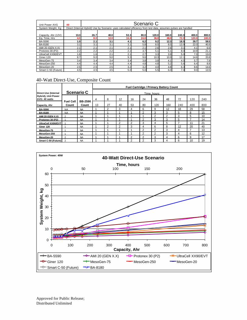
Approved for Public Release; Distributed Unlimited
System Weight, Kg
Capacity, Ahr (12V) 13.3 26.7 40.0 53.3 80.0 120.0 160.0 240.0 400.0 800.0Eq. Time, Hrs 4.0 8.0 12.0 16.0 24.0 36.0 48.0 72.0 120.0 240.0BA-5590 1.0 2.1 3.1 4.1 6.2 9.2 12.3 18.5 29.7 59.5BA-8180 3.1 3.1 3.1 3.1 5.8 8.5 8.5 13.9 22.0 40.9AMI 20 (GEN X.X) 2.1 2.1 2.1 2.1 2.1 2.6 2.6 3.1 4.1 6.6Protonex 30 (P2) 2.2 2.2 2.2 2.2 3.7 5.1 5.1 8.0 10.9 21.1UltraCell XX90/EVT 1.6 1.6 2.1 2.1 2.7 3.3 3.9 5.0 7.3 13.0Giner 120 8.7 9.0 9.0 9.3 9.6 10.3 10.9 12.1 14.6 20.8MesoGen-75 3.4 3.4 3.4 3.4 3.8 3.8 4.1 4.5 5.7 7.9MesoGen-250 4.4 4.4 4.4 4.4 4.8 4.8 5.2 5.6 6.4 8.8MesoGen-20 2.5 2.5 2.5 3.2 3.2 4.0 4.8 6.3 8.6 14.6Smart C-50 (Future) 4.5 4.5 4.5 5.0 5.0 5.5 6.0 7.0 9.0 13.5
Direct (Internal Hybrid) Use by Scenario: uses calculated efficiency from test data, assumes pulses are handled40Unit Power AVG Scenario C
40-Watt Direct-Use, Composite Count
4 8 12 16 24 36 48 72 120 240
Capacity, Ahr 13 27 40 53 80 120 160 240 400 800BA-5590 NA NA 1 2 3 4 6 9 12 18 29 58BA-8180 NA NA 1 1 1 1 2 3 3 5 8 15AMI 20 (GEN X.X) 2 NA 1 1 1 1 1 2 2 3 5 10Protonex 30 (P2) 1 NA 1 1 1 1 2 3 3 5 7 14UltraCell XX90/EVT 1 NA 1 1 2 2 3 4 5 7 11 21Giner 120 1 NA 1 2 2 3 4 6 8 12 20 40MesoGen-75 1 NA 1 1 1 1 2 2 3 4 7 13MesoGen-250 1 NA 1 1 1 1 2 2 3 4 6 12MesoGen-20 2 NA 1 1 1 2 2 3 4 6 9 17Smart C-50 (Future) 2 NA 1 1 1 2 2 3 4 6 10 19
Direct-Use (Internal Hybrid), Unit Power AVG: 40 watts
Scenario CFuel Cartridge / Primary Battery Count
Time, hours
Fuel Cell Count
BB-2590 Count
40-Watt Direct-Use Scenario
0
10
20
30
40
50
60
0 100 200 300 400 500 600 700 800Capacity, Ahr
Sys
tem
Wei
gh
t, k
g
0 50 100 150 200Time, hours
BA-5590 AMI 20 (GEN X.X) Protonex 30 (P2) UltraCell XX90/EVT
Giner 120 MesoGen-75 MesoGen-250 MesoGen-20
Smart C-50 (Future) BA-8180
System Power: 40W

Approved For Public Release Distributed Unlimited
Acknowledgements NSWC Crane would like to thank the following organizations and individuals for their support and cooperation. • Mr. Nick Sifer (CERDEC – Ft Belvoir) – Smart Fuel Cell C20 20W DMFC & A50 50W DMFC – UltraCell Alpha 20W RMFC – Ultra Cell XX90 45W RMFC • Captain David Pfahler (AFRL – WPAFB) – Protonex 30W PEM • Dr. Deryn Chu (ARL – Adelphi, MD) – Giner 250W DMFC – Mesoscopic Devices 20W DMFC • DARPA – Dr. Valerie Browning – Adaptive Material Inc Gen 1.9 20W SOFC – Adaptive Material Inc Gen 1.9 20W SOFC – Mesoscopic Devices 75W DMFC • Major Alan Stocks (ONR Code 353) – Mesoscopic Devices 250W SOFC NSWC Crane would like to thank the following companies for bringing their technologies to NSWC Crane for evaluation. • Adaptive Materials Inc. • Protonex Technology Corporation NSWC Crane would like to thank the following companies for sharing technical and performance data/projections of their future technologies. • Adaptive Materials Inc. • Protonex Technology Corporation • UltraCell • Mesoscopic Devices • Smart Fuel Cell

Approved for Public Release; Distribution Unlimited
Reference:
1. Department of Navy, Naval Sea Systems Command Warfare Centers, 5521 Ser 00/168, 18 June 04.
2. Ultralife; Product Data Sheet, http://www.ultralifebatteries.com
3. MIL/BA-5590/U Battery, MIL Power BA-5590 Data Sheet; www.milpower.co.uk
4. Brentronics Inc., BB-2590/U Data Sheet; Brentronics Inc., www.brentronics.com
5. The BA-8180/U, Electric Fuel BA-8180/U Data Sheet
6. High Capacity Li Ion BB-2590: Performance and Safety Characteristics; Mike
Sink, Saft America, Inc., 41st Power Source Conference, June 2004.