m& e n vironen et l talio journal of petroleum & t f e o c
TRANSCRIPT
Open AccessResearch Article
Mahmoud, J Pet Environ Biotechnol 2016, 7:2 DOI: 10.4172/2157-7463.1000266
Volume 7 • Issue 2 • 1000266J Pet Environ BiotechnolISSN: 2157-7463 JPEB, an open access journal
AbstractThe hydrodynamic separator unit is established for the removal and recovery of oil from wastewater, Which
including, flotation system and sedimentation of solid materials. Several operating parameters are investigated such as feed flow rate, percent of oil in feed flow rate, percent of water in feed flow rates, air flow rate and type of water (salinity). Separator unit is found to be simple in the design, fast in operation and effective under all possible operating conditions.
Hydrodynamic Separator Unit for Removal and Recovery Oil from WastewaterMohamed Ahmed Mahmoud1,2*1Nuclear Material Authority, Cairo, Egypt2Faculty of Engineering, Jazan University, Jazan, Saudi Arabia
Keywords: Hydrodynamic; Oil; Wastewater; Flotation; Recovery
IntroductionCar service stations, restaurants, machine maintenance, oil mills,
food- processing factories are the main sources of oil and grease in wastewater. In addition, oil tanker accidents, explosions, sea pipelines, oil drilling operation and oil explorations and productions are the principal causes of oil in marine areas. The failure of some of the conventional wastewater treatment plants is mainly because of the presence of excess oil and grease [1]. Oil pollution has harmful effects on sea life, economy, tourism, wastewater treatment plants and human activities because of its coating properties. Common methods are used for the removal of oil spill from marine areas such as booms, chemical [2], mechanical [3-6] and biological [7]. The disadvantages of some of these methods are their inefficient, high cost and low rate of removal and recovery of oil from sea water. Therefore, the removing and recovering of oil spill from marine areas have been studied by numerous researches [8-13].
The present work is to design a simple system for removal and recovery of oil from wastewater. Operating parameters such as feed flow rate, percent of oil in feed flow rate, percent of water in feed flow rate, air flow rate, type of water (salinity) and oil film thickness are studied.
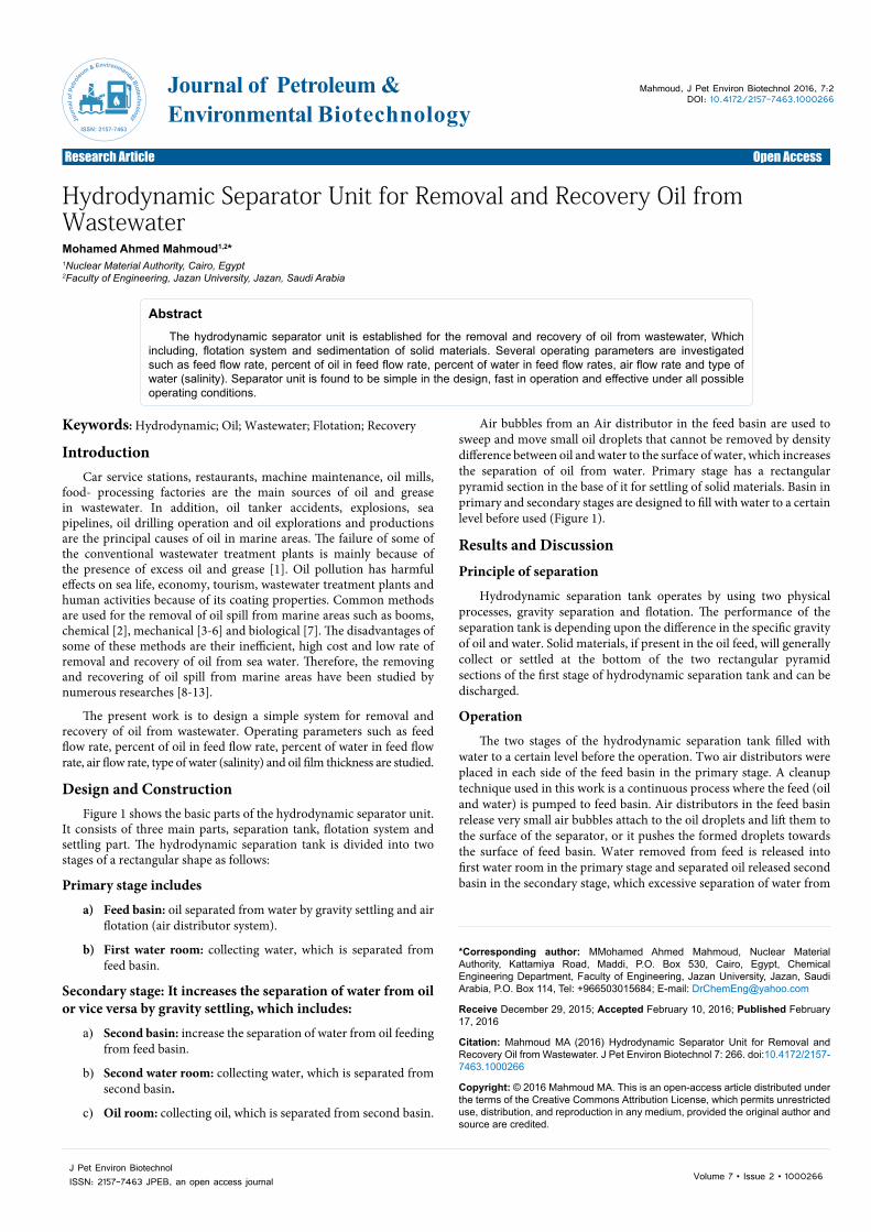
Design and Construction Figure 1 shows the basic parts of the hydrodynamic separator unit.
It consists of three main parts, separation tank, flotation system and settling part. The hydrodynamic separation tank is divided into two stages of a rectangular shape as follows:
Primary stage includes
a) Feed basin: oil separated from water by gravity settling and airflotation (air distributor system).
b) First water room: collecting water, which is separated fromfeed basin.
Secondary stage: It increases the separation of water from oil or vice versa by gravity settling, which includes:
a) Second basin: increase the separation of water from oil feeding from feed basin.
b) Second water room: collecting water, which is separated fromsecond basin.
c) Oil room: collecting oil, which is separated from second basin.
Air bubbles from an Air distributor in the feed basin are used to sweep and move small oil droplets that cannot be removed by density difference between oil and water to the surface of water, which increases the separation of oil from water. Primary stage has a rectangular pyramid section in the base of it for settling of solid materials. Basin in primary and secondary stages are designed to fill with water to a certain level before used (Figure 1).
Results and DiscussionPrinciple of separation
Hydrodynamic separation tank operates by using two physical processes, gravity separation and flotation. The performance of the separation tank is depending upon the difference in the specific gravity of oil and water. Solid materials, if present in the oil feed, will generally collect or settled at the bottom of the two rectangular pyramid sections of the first stage of hydrodynamic separation tank and can be discharged.
Operation
The two stages of the hydrodynamic separation tank filled with water to a certain level before the operation. Two air distributors were placed in each side of the feed basin in the primary stage. A cleanup technique used in this work is a continuous process where the feed (oil and water) is pumped to feed basin. Air distributors in the feed basin release very small air bubbles attach to the oil droplets and lift them to the surface of the separator, or it pushes the formed droplets towards the surface of feed basin. Water removed from feed is released into first water room in the primary stage and separated oil released second basin in the secondary stage, which excessive separation of water from
*Corresponding author: MMohamed Ahmed Mahmoud, Nuclear MaterialAuthority, Kattamiya Road, Maddi, P.O. Box 530, Cairo, Egypt, Chemical Engineering Department, Faculty of Engineering, Jazan University, Jazan, Saudi Arabia, P.O. Box 114, Tel: +966503015684; E-mail: [email protected]
Receive December 29, 2015; Accepted February 10, 2016; Published February 17, 2016
Citation: Mahmoud MA (2016) Hydrodynamic Separator Unit for Removal and Recovery Oil from Wastewater. J Pet Environ Biotechnol 7: 266. doi:10.4172/2157-7463.1000266
Copyright: © 2016 Mahmoud MA. This is an open-access article distributed under the terms of the Creative Commons Attribution License, which permits unrestricted use, distribution, and reproduction in any medium, provided the original author and source are credited.
Journal of Petroleum & Environmental BiotechnologyJo
urna
l of P
etro
leum & Environmental Biotechnology
ISSN: 2157-7463
Citation: Mahmoud MA (2016) Hydrodynamic Separator Unit for Removal and Recovery Oil from Wastewater. J Pet Environ Biotechnol 7: 266. doi:10.4172/2157-7463.1000266
Page 2 of 3
Volume 7 • Issue 2 • 1000266J Pet Environ BiotechnolISSN: 2157-7463 JPEB, an open access journal
oil or vice versa by gravity settling. After that, oil is released into an oil collecting room and water removed from the second basin is released into second water room. Finally, the recovered oil discharge from oil room to a storage tank and separated water in the water collection rooms are discharged.
Operating variablesUsed motor oil collected from car maintenance centers in Jazan, KSA,
was used in all experiments. Properties of used motor oil are presented in Table 1. The amount of oil recovered from the hydrodynamic unit is determined by mass using an electronic balance (GH-7001, China), at interval time (Kg/min). The concentration of oil in water is determined by FluoroCheck II (ARJAY ENGINEERING Ltd).
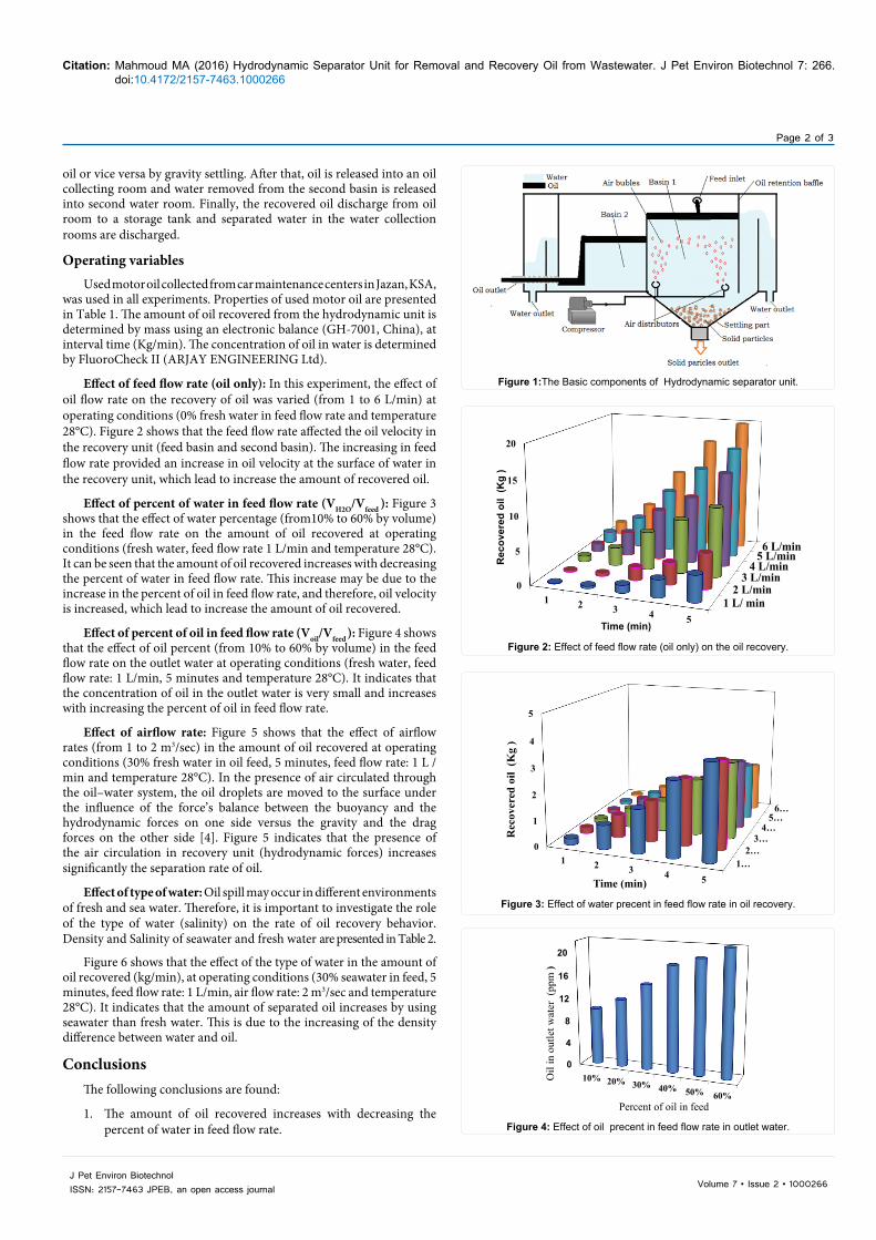
Effect of feed flow rate (oil only): In this experiment, the effect of oil flow rate on the recovery of oil was varied (from 1 to 6 L/min) at operating conditions (0% fresh water in feed flow rate and temperature 28°C). Figure 2 shows that the feed flow rate affected the oil velocity in the recovery unit (feed basin and second basin). The increasing in feed flow rate provided an increase in oil velocity at the surface of water in the recovery unit, which lead to increase the amount of recovered oil.
Effect of percent of water in feed flow rate (VH2O/Vfeed ): Figure 3 shows that the effect of water percentage (from10% to 60% by volume) in the feed flow rate on the amount of oil recovered at operating conditions (fresh water, feed flow rate 1 L/min and temperature 28°C). It can be seen that the amount of oil recovered increases with decreasing the percent of water in feed flow rate. This increase may be due to the increase in the percent of oil in feed flow rate, and therefore, oil velocity is increased, which lead to increase the amount of oil recovered.
Effect of percent of oil in feed flow rate (Voil/Vfeed ): Figure 4 shows that the effect of oil percent (from 10% to 60% by volume) in the feed flow rate on the outlet water at operating conditions (fresh water, feed flow rate: 1 L/min, 5 minutes and temperature 28°C). It indicates that the concentration of oil in the outlet water is very small and increases with increasing the percent of oil in feed flow rate.
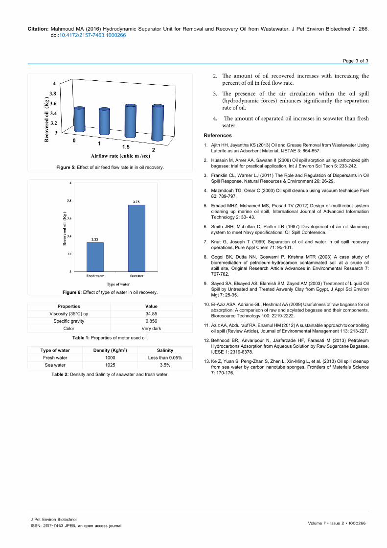
Effect of airflow rate: Figure 5 shows that the effect of airflow rates (from 1 to 2 m3/sec) in the amount of oil recovered at operating conditions (30% fresh water in oil feed, 5 minutes, feed flow rate: 1 L /min and temperature 28°C). In the presence of air circulated through the oil–water system, the oil droplets are moved to the surface under the influence of the force’s balance between the buoyancy and the hydrodynamic forces on one side versus the gravity and the drag forces on the other side [4]. Figure 5 indicates that the presence of the air circulation in recovery unit (hydrodynamic forces) increases significantly the separation rate of oil.
Effect of type of water: Oil spill may occur in different environments of fresh and sea water. Therefore, it is important to investigate the role of the type of water (salinity) on the rate of oil recovery behavior. Density and Salinity of seawater and fresh water are presented in Table 2.
Figure 6 shows that the effect of the type of water in the amount of oil recovered (kg/min), at operating conditions (30% seawater in feed, 5 minutes, feed flow rate: 1 L/min, air flow rate: 2 m3/sec and temperature 28°C). It indicates that the amount of separated oil increases by using seawater than fresh water. This is due to the increasing of the density difference between water and oil.
ConclusionsThe following conclusions are found:
1. The amount of oil recovered increases with decreasing the percent of water in feed flow rate.
Figure 1:The Basic components of Hydrodynamic separator unit.
1 L/ min2 L/min
3 L/min4 L/min
5 L/min6 L/min
0
5
10
15
20
1 2 3 4 5
Rec
over
ed o
il (K
g )
Time (min)
Figure 2: Effect of feed flow rate (oil only) on the oil recovery.
1…2…
3…4…
5…6…
0
1
2
3
4
5
1 2 3 4 5
Rec
over
ed o
il (K
g )
Time (min)
Figure 3: Effect of water precent in feed flow rate in oil recovery.
0
4
8
12
16
20
10% 20% 30% 40% 50% 60%
Oil
in o
utle
t wat
er (
ppm
)
Percent of oil in feed
Figure 4: Effect of oil precent in feed flow rate in outlet water.
Citation: Mahmoud MA (2016) Hydrodynamic Separator Unit for Removal and Recovery Oil from Wastewater. J Pet Environ Biotechnol 7: 266. doi:10.4172/2157-7463.1000266
Page 3 of 3
Volume 7 • Issue 2 • 1000266J Pet Environ BiotechnolISSN: 2157-7463 JPEB, an open access journal
Properties ValueViscosity (35°C) cp 34.85
Specific gravity 0.856Color Very dark
Table 1: Properties of motor used oil.
Type of water Density (Kg/m3) SalinityFresh water 1000 Less than 0.05%Sea water 1025 3.5%
Table 2: Density and Salinity of seawater and fresh water.
3
3.2
3.4
3.6
3.8
4
0 1 1.5 2
Rec
over
ed o
il (K
g )
Airflow rate (cubic m /sec)
Figure 5: Effect of air feed flow rate in in oil recovery.
3.33
3.75
3
3.2
3.4
3.6
3.8
4
Fresh water Seawater
Rec
over
ed o
il (K
g )
Type of water
Figure 6: Effect of type of water in oil recovery.
2. The amount of oil recovered increases with increasing thepercent of oil in feed flow rate.
3. The presence of the air circulation within the oil spill(hydrodynamic forces) enhances significantly the separationrate of oil.
4. The amount of separated oil increases in seawater than freshwater.
References
1. Ajith HH, Jayantha KS (2013) Oil and Grease Removal from Wastewater Using Laterite as an Adsorbent Material, IJETAE 3: 654-657.
2. Hussein M, Amer AA, Sawsan II (2008) Oil spill sorption using carbonized pith bagasse: trial for practical application, Int J Environ Sci Tech 5: 233-242.
3. Franklin CL, Warner LJ (2011) The Role and Regulation of Dispersants in Oil Spill Response, Natural Resources & Environment 26: 26-29.
4. Mazmdouh TG, Omar C (2003) Oil spill cleanup using vacuum technique Fuel 82: 789-797.
5. Emaad MHZ, Mohamed MS, Prasad TV (2012) Design of multi-robot system cleaning up marine oil spill, International Journal of Advanced Information Technology 2: 33- 43.
6. Smith JBH, McLellan C, Pintler LR (1987) Development of an oil skimming system to meet Navy specifications, Oil Spill Conference.
7. Knut G, Joseph T (1999) Separation of oil and water in oil spill recovery operations, Pure Appl Chem 71: 95-101.
8. Gogoi BK, Dutta NN, Goswami P, Krishna MTR (2003) A case study of bioremediation of petroleum-hydrocarbon contaminated soil at a crude oil spill site, Original Research Article Advances in Environmental Research 7: 767-782.
9. Sayed SA, Elsayed AS, Elareish SM, Zayed AM (2003) Treatment of Liquid Oil Spill by Untreated and Treated Aswanly Clay from Egypt, J Appl Sci Environ Mgt 7: 25-35.
10. El-Aziz ASA, Adriane GL, Heshmat AA (2009) Usefulness of raw bagasse for oil absorption: A comparison of raw and acylated bagasse and their components, Bioresource Technology 100: 2219-2222.
11. Aziz AA, Abdulrauf RA, Enamul HM (2012) A sustainable approach to controlling oil spill (Review Article), Journal of Environmental Management 113: 213-227.
12. Behnood BR, Anvaripour N, Jaafarzade HF, Farasati M (2013) Petroleum Hydrocarbons Adsorption from Aqueous Solution by Raw Sugarcane Bagasse, IJESE 1: 2319-6378.
13. Ke Z, Yuan S, Peng-Zhan S, Zhen L, Xin-Ming L, et al. (2013) Oil spill cleanup from sea water by carbon nanotube sponges, Frontiers of Materials Science 7: 170-176.