make the right moves with powders - chemical …...feeder to a hammer mill. the blended material...
TRANSCRIPT

Powder eHandbook
Make the Right Moves with Powders


Table of ContentsInstall Pneumatic Conveyors Correctly 7Follow 10 steps to prevent a variety of common problems
Carefully Select your Vacuum Conveying Equipment 13Safety, security and sanitation are critical operational aspects to consider
Take a Closer Look at Tubular Drag Conveying 18Technology offers a cost-effective and energy saving alternative to pneumatic conveying
Understand Accuracy in a Bin Level Monitoring System 26Single-point and multi-point systems each have their pros and cons
Product ReleasesACS Valves 3www.acsvalves.com
Kuriyama 5www.kuriyama.com
3
Feeder Handles Hard-To-Convey MaterialsDesign optimizes material flow density and improves conveying efficiency
FInE PowDERS can easily over-aerate, which reduces material feed efficiency in high-pressure pneumatic conveying applications. To combat this, ACS Valves designed the BT Series Blow-Through Feeder/Airlock to ensure optimal throughput of hard-to-convey materials. The BT Series 12-vane rotary valve design decreases excess aeration of the material during convey-ing with an integrated vent port on the return side of the valve housing that vents pocket air leakage. The BT design element minimizes the flow path of air through the rotor clearances, improving material pocket release. And with minimal air leak-age, the resulting low pressure drop of the BT Series optimizes material flow density, improves material conveying efficiency, and reduces total compressed air consumption.Cast in North America, BT Series housings ensure superior strength in the composition and solidification of the housing’s metallurgy, providing optimal service in high-pressure applications up to 20 psig.
ACS Valves • 800-655-3447 • www.acsvalves.com

Seamlessly Integrated Bulk Material Load-Out System
Hapman will seamlessly integrate each piece of bulk material handling equipment to work as a complete system. This illustration represents a packaging operation for fertilizer. The two materials are moved from bulk bag unloaders to an upper mezzanine with Helix flexible screw conveyors. A third material is transferred from a storage silo to the mezzanine with a tubular drag chain conveyor. Each material is precisely metered with a volumetric feeder to a hammer mill. The blended material from the mill is carried to a truck load-out area. This system is completely automated with integral controls.
For more information on Hapman bulk solids handling equipment and engineered systems, call (800) 427-6260, e-mail [email protected], or visit hapman.com.
Process Color Master using Hapman colorsHapman People and Expertise
Tubular Drag ConveyorBulk Bag Unloader Helix® Flexible Screw Conveyor Volumetric Feeder
There’s something differentthat you’re looking for in a material handling system. Sure, you want superior performance. That’s a given. Let’s talk about what you don’t want:
And here’s what Hapman
will get you:
The right system starts with the right people.(And that makes all the difference.)
MORE THAN EQUIPMENT
We get it.Meet Hapman. Whether custom-made
or custom-matched, all of our systems come with real people who
care about your success.
Process Color Master using Hapman colors
For a free test of your material, visit:hapman.com/material-test.
Boilerplate design
Major customization markups
Difficult parts replacement
Sleepless nights
Your ideal design
Free material testing
Guaranteed performance
Round-the-clock support
© 2014 Hapman. All rights reserved.
4

Ad IndexVac-U-Max 2www.vac-u-max.com
Hapman 4www.hapman.com
Kuriyama 6www.kuriyama.com
BinMaster 9www.binmaster.com
ACS Valves 12www.acsvalves.com
Brookfield 17www.brookfieldengineering.com
Federal Equipment 21www.fedequip.com
Arizona Instrument 25www.azic.com
Volkmann 29www.volkmannUSA.com
5
KURIyAMA oF America’s new line of Tigerflex Voltbuster food-grade material-handling hoses have been designed for high-static applications such as the transfer of powders, pellets and other granular materials.
The hose’s design helps dissipate static charges to ground, helping prevent static build-up and re-ducing the potential for dangerous electrostatic discharges. They have been constructed with static dissipative plastic materials, allowing for the free flow of static to the hose’s embedded grounding wire. The light-weight design of the hoses can help reduce injuries related to heavier metal hoses.
The “Volt Series” hose-tube construction includes abrasion-resistant food-grade polyurethane to ensure the purity of transferred materials. In addition, the grounding wire has been encapsulated in a rigid PVC helix on the exterior of the hose, eliminating the risk of contaminating the transferred materials. The VLT-SD Series is con-structed the same, but has an FDA polyester fabric reinforcement to handle both suction and higher pressure discharge applications. New 2- and 8-in. ID sizes have been recently added to this product line.
Food-Grade Hoses Handle High-Static ApplicationsHose design helps dissipate static charges to ground.
Kuriyama of America, Inc. • 847-755-0360 • www.kuriyama.com

TIGERFLEXISO 9001-2000
REGISTERED Q.M.S.
™
THE ASSOCIATION FOR HOSE ANDACCESSORIES DISTRIBUTION Made In USA
Static Dissipative Food Grade Material Handling HosesSuperior Static Protection!
Durable Abrasion Resistant!
Food Grade!
Light Weight!
Thermoplastic Industrial Hoses
EDITION 0114
VLT-SD™
VOLT™WINNER!
CHEMICAL PROCESSING
BY
6

Install Pneumatic Conveyors CorrectlyFollow 10 steps to prevent a variety of common problems
By Thomas R. Blackwood, Healthsite Associates
PnEUMATIC ConVEyInG is one of the most versatile ways to move solids over moderate distanc-es. So, not surprisingly, Chemical Processing over the years has published a number of articles (e.g., Ref. 1) on the design, installation and operation of dense- and dilute-phase pneumatic conveyors. Several mod-els and a whole host of data from research groups also are available. However, even the best model and data can only go so far. Actual performance depends upon mechanical accuracy. For instance, a small un-noticed leak can kill the performance of a pneumatic conveyor — so much for having a good model. Ad-ditional problems may result from non-uniformity of the flow or local changes in the solids-to-air ratio.
The reality of most plant environments is that the quest to keep costs low can dictate design consider-ations and spell trouble, particularly when using old equipment for a new project.
However, you can take a number of steps to prevent problems.
Top 10 TIpS
I have found the following pointers useful both for planning new systems and modifying existing ones.
1. Put lifts before horizontal runs. In most conveyors the feed point has the lowest gas velocity and particles may fall out of suspension. This can be offset by line size changes but standard line sizes can force you to push the velocity higher than desired, especially near the end of the line. As the pressure along the line goes down, the velocity goes up. By raising the conveyor in front of horizontal runs instead of at the end, particles have a chance to accelerate toward the gas
velocity and gain momentum, mainly because the choking velocity is generally lower than the saltation velocity. The downside is cost. Unless you are going over a building, the extra support can be expensive.
2. Minimize elbows and angled runs. Pressure drop and attrition are highest in elbows (for the ef-fective distance solids travel). Most of the wear and maintenance seen in pneumatic conveyors is due to the elbows; so it often is best not to use too many. The major exception to minimiz-ing the number of elbows in a system is for a line that needs to go up and then horizon-tal. While an angled run offers the shortest distance between two points, it does not have lowest pressure drop. Indeed, a convey line go-ing up at a 45° angle has much higher pressure drop than a horizontal and vertical line with three elbows. Putting elbows too close together is another major mistake, due to acceleration effects. Many models just count the amount of elbows — but placement in the layout is more important. The lowest number of elbows is not always optimum.
3. Calculate velocity every 10 to 20 feet on the line. Don’t rely only on measurements of the pickup velocity or the maximum and minimum veloci-ties in the system. The velocity of the gas and particulates should be determined along the entire length of the line, to ensure that the cor-rect density is used to determine the choking and saltation velocities. This makes the design a trial-and-error calculation. Shortcut design methods often overlook this critical step.
7

4. Check acceleration lengths at feeders and around elbows. It takes time for a particle to reach its slip velocity (effective velocity below the gas velocity). Particles also must be dispersed across the convey line so the solids-to-air ratio is uniform — otherwise the saltation effects will be drastically different. You could have high localized solids-to-air ratios that would throw a dilute-phase conveyor into dense phase and slug flow. The acceleration length can be determined using the graphic technique of Rose and Duckworth [2] or the Jotaki and Tomita method [3]. For a quick estimate of the optimal spacing of elbows or feeders from each other, use a value between the square root and the cube root of the stopping distance for the particle in feet:
Xs = (Vg dp2 ρs)/(18 μg)
where Vg is gas velocity, ft/s; dp is particle diam-eter, ft; ρs is effective particle density, lb/ft3; and μg is gas viscosity, lb/ft-s.
Sometimes it is obvious by looking at a convey-ing line that the elbows are too close together and the layout was not well planned (e.g., Figure 1).
8
PooR LAyoUT
Figure 1. Sometimes no detailed analysis is needed to spot a bad layout.
RUnnInG A ConVEy TESTOne of the most important parts of putting in a new conveying line is correct testing, especially on a new product or long layout. Most equipment manufacturers will perform a test for a nominal fee that seldom covers its real cost. Remember vendors are not clairvoyant and usually don’t understand your overall process as well as you do. Some engineers arrive at a test expecting the manufacturer to guide them through the testing process and to point out what the buyer needs to do. That ap-proach doesn’t sell a lot of pneumatic conveyors, which after all is the vendor’s objective. Most manufacturers’ test setups are not research systems but demonstration devices. So, it is best to have a test plan that you and the vendor agreed upon beforehand. This may mean bringing in additional testing resources at your cost to supplement what is provided.
PoInTERS1. Look at particle attrition. Conduct particle sizing tests
and examine the particles under a microscope.2. Attempt to find the choking and saltation velocities. Com-
pare these to calculated values. Design the system at 1.5 times the maximum value but plan to reduce this velocity after installation (by reducing the blower flow rate).
3. Run at both twice and half of the expected design velocity.
4. Ensure the solids-to-air ratio is constant during the test.5. Calculate velocity along the line. This requires data on
pressure and temperature.6. Roughly determine the particle-to-gas velocity along a
straight section of pipe.7. Get the layout close to what is expected in the plant.
Try to match elbows and lift location.8. Make some of your own measurements. This keeps the
vendor honest.9. Inspect the piping. Pay attention to the type of joints,
construction material, elbow R/D, feeder and collector details.
10. Run a “power failure” test. Deliberately stop the gas flow and let the line sit overnight, if possible. Failures happen. The best place to find out their consequenc-es is in the lab.
While following the test and designing the conveyor, enjoy the process of understanding your material. Imag-ine yourself running around inside the pipe. Pneumatic conveyors are powerful and the solids convey consider-able force. I was reminded of that one time when every few hours we heard a clanking noise in a vertical section on a recirculation pneumatic conveying blender. We shut down the conveyor and removed the bottom elbow to find a 6-in.-long, 1-in.-diameter bolt that had made several trips through the system. Oh well!
“ Small leaks can cripple operation by changing the difference between the gas and saltation velocity.”

Enhance Safety and Efficiency!
Non-Contact Inventory Management in Bins & Silos
RL • Acoustics-based, continuous level indicator for dusty environments
• Works in powders and solids including low dielectric materials
• Self-cleaning, minimal- maintenance sensor
NEW! BinMaster RL Level Sensor
BINMaSter level CoNtrolSwww.binmaster.com • [email protected]
402-434-9102©2014 BinMaster, Lincoln, NE 68507 uSA
3DLevelScannerAccurate Volume & 3D Mapping• True volume measurement for silos• Works reliably in high levels of dust• Accurate, multiple-point measurement• Measures and maps bin topography• Eliminates climbing for employee safety
9
5. Be careful with pipe joints. Piping should be carefully aligned during installation. The use of slip-couplings can allow for gaps or pinched gaskets, even with tie-bars. Even welded pipe can be improperly fabricated at the flange due to misalignment and “cat teeth” from the welds. When joining pipe, specialized welding methods can prevent slag inside the pipe.
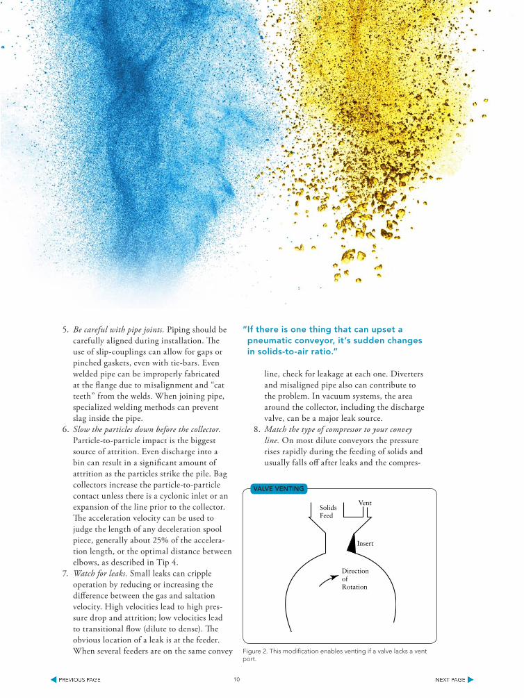
6. Slow the particles down before the collector. Particle-to-particle impact is the biggest source of attrition. Even discharge into a bin can result in a significant amount of attrition as the particles strike the pile. Bag collectors increase the particle-to-particle contact unless there is a cyclonic inlet or an expansion of the line prior to the collector. The acceleration velocity can be used to judge the length of any deceleration spool piece, generally about 25% of the accelera-tion length, or the optimal distance between elbows, as described in Tip 4.
7. Watch for leaks. Small leaks can cripple operation by reducing or increasing the difference between the gas and saltation velocity. High velocities lead to high pres-sure drop and attrition; low velocities lead to transitional flow (dilute to dense). The obvious location of a leak is at the feeder. When several feeders are on the same convey
line, check for leakage at each one. Diverters and misaligned pipe also can contribute to the problem. In vacuum systems, the area around the collector, including the discharge valve, can be a major leak source.
8. Match the type of compressor to your convey line. On most dilute conveyors the pressure rises rapidly during the feeding of solids and usually falls off after leaks and the compres-
10
SolidsFeed
DirectionofRotation
Vent
Insert
VALVE VEnTInG
Figure 2. This modification enables venting if a valve lacks a vent port.
“ If there is one thing that can upset a pneumatic conveyor, it’s sudden changes in solids-to-air ratio.”

sor slip have stabilized. A large surge tank can help but adds cost to the system. Volumetric feeders are just that — the solids-to-air ratio will vary over a conveying cycle. As the com-pressor heats up, the gas velocity can increase in small or light-weight compressors, leading to attrition of the solids. When a conveying system is used continuously, this usually is not a problem, except maybe during start-up. Oversized compressors that run at low speeds can be sluggish and unable to keep up with leaks or sudden changes in solids-to-air ratio. This is especially true when spare equipment is being re-used.
9. Vent the feeder valves and factor the amount lost into the design. If there is one thing that can upset a pneumatic conveyor it’s sudden changes in solids-to-air ratio. An unvented solids feeder prevents the pockets from filling uniformly and can fluidize the solids in the tank or bin above the feeder. The solids can flood the valve, prompting over-
consolidation and bridging. Not only does the solids-to-air ratio change but particles also can be pinched in the feeder and break. Figure 2 shows a way to vent the valve in the absence of a vent port supplied by the manu-facturer. Note in particular in the figure the use of an insert to prevent particles being pinched between the housing and rotor.
10. Look for frictional differences between products. Sometimes after conveying one material and either making a change to the ingredients or trying to convey a different material we forget that the particles may not behave the same. While basic physical properties can be helpful in predicting a problem you can’t go wrong with a few tests. Frictional changes can be subtle. Even the same product can have different shear rates and pickup velocities. In addition, don’t for-get to check the characteristics of an existing material after conveying a new material. A fine coating or change in surface may alter the pressure drop in the system.
THomAS R. BlACKwood is director of technology for
Healthsite Associates, Ballwin, Mo. E-mail him at [email protected].
11
REFEREnCES1. Haraburda, S.S., “7 steps to efficient conveying,” Chemical Processing, Vol. 63 (2), p. 57 (February 2000). 2. Duckworth, R.A. and H.E. Rose, “Transport of Solid Particles in Liquid and Gases,” Engineer, Vol. 227
(5,905), pp. 392-396, 430-433 and 478-483, London (1969).3. Jotaki, Y. and Y. Tomita, “Flow in the Acceleration Region of Pneumatic Transport of Granular Solids in
Vertical Pipes,” Proceedings of Pneumotransport 3, pp. 99-108, Bath, U.K. (April 1976).
“ Even the same product can have different shear rates and pickup velocities.”

Rotary valves are not commodities. For every material, every industry and every regulation, ACS has a valve to optimize the performance of your bulk handling system.
One of these things is not like the other.
Blow-Through Series
CDC-CI Series
Aero-Flow Series
DR-S Series
Quick-Clean Stainless Steel
Quick-Clean Cast Iron
Discover what ACS Valves can do for your business.
acsvalves.com800-655-3447
12

Carefully Select your Vacuum Conveying EquipmentSafety, security and sanitation are critical operational aspects to consider
By Nick Hayes, Volkmann, Inc.
THE TRAnSFER of powder and granules is a difficult business. Given the wide variety of products with their range of properties compounded by differing applica-tions and even the installation environment, many different issues must be considered when designing a system to transport these materials. Our increased awareness of the risks of an explosion, hazardous emissions and environmental consideration gives the modern facilities manager a serious challenge when selecting suitable equipment.
Because ample evidence exists of the need for dust-free powder transfer to minimize these dangers, modern conveyor manufacturers are increasingly raising the standards of the equipment available.
Three critical operational aspects should be identi-fied before investing in any system. These are:
• Safety — does the system eliminate the explosion or emissions risk?
• Security — does the system protect the product from contaminates and / or protect the operators from the material being transferred such as in the case of an antibiotic?
• Sanitation — does the system provide easy access for cleaning, rapid changes of product and main-tenance of the equipment?
PowDER ConVEyInG wITH VACUUM
Vacuum conveyors are increasingly being found as the most suitable method of powder transfer, meeting all three criteria due to their inherent “closed system” functionality, thereby providing easy and safe transfer. One obvious advantage to conveying under vacuum is that the system is leak free by definition. However, there’s much more to this technique that qualifies it as the most effective.
For the purpose of this article we are considering in-plant transfer using conveying systems with transfer rates from as little as a few hundred lb/hr to rates in the 10,000-lb/hr range. Generally speaking, these systems have conveying line diameter sizes of up to 4 in. and have particular advantages when it comes to safety.
SAFE ConVEyInG
Over the past few years, the industry has become increasingly aware of the danger of powder explo-sions. While the legislative requirements on safe operation may not be as stringent here in North America as they are within Europe, recent changes to NFPA 654 and similar standards, compounded by plant explosions such as the Georgia sugar refin-ery, are leading to an ever-increasing need to protect
13

14
against such dangers during powder transfer. When considering for an explosion risk, any vessel hav-
ing a volume of less than eight cubic feet is exempt from the NFPA 654 requirement to provide explosion vents or quick closure valves. Even so, any explosion, no matter how small the vessel might be, is a potential issue. The use of compressed air driven vacuum pumps, and particularly those that are certified as explosion-proof, such as European systems under the ATEX 94/9/EG & 99/92/EG guidelines, provide a safe transfer system.
The ATEX standard identifies a list of thirteen potential ignition sources as follows:
1. Chemical reaction2. Hot surfaces3. Mechanical sparks4. Flames, hot gases5. Electric units6. Flash of lightning7. Electric compensation currents8. Ultrasonic9. High frequency radiation10. Electromagnetic waves11. Adiabatic compression12. Ionizing radiation13. Electrostatic charges Volkmann vacuum conveyors, when suitably grounded,
are certified as safe for use with any powder that has a Mini-mum Ignition Energy (MIE) of greater than 1 mJ when trans-ferred in a powder-only environment. MIE is a much more suitable measurement for determining explosion risk than the commonly used Kst value, which actually measures the rate of an explosion, in that MIE measures the amount of energy required to generate a spark of sufficient magnitude to cause ignition of the powder/air mixture. With no ignition, there can be no explosion. In simple terms, MIE is established by testing where the amount of energy required to cause ignition is lowered stage by stage until it no longer occurs (Figure 1).
Examples of Typical MIE values:Toner ..............................1mJ Aluminum Powder ..........3 mJCornstarch ............. 3 – 5 mJ Paracetamol ................< 10 mJEpoxy Resin ...............10 mJ Magnesium....................20 mJSugar .......................... 30 mJ Cellulose ........................40 mJWheat Flour ............... 50 mJ PVC ..........................1,500 mJ
(Note: The above are typical and for general reference purposes only. MIE can vary with individual site conditions. Testing should be carried out with the exact product in condi-tions as close to actual use to establish the specific values.)
Where flammable gases are present, such as in Class 1 Div 1 applications, further protection is provided by using an INEX certified Volkmann Multijector system which can be run in an inert explosion proof manner using nitrogen as the conveying medium, is a safe approach.
MIE (Minimum Ignition Energy) No Ignition
COMBUSTIBLE/FUEL CONCENTRATION(Product to Air Ratio)
IGNITION ENERGY
IGNITION
0 100%
mJ
Figure 1. MIE measures the amount of energy required to generate a spark of sufficient magnitude to cause ignition of the powder/air mixture.
MInIMUM IGnITIon EnERGy

15
SECURE ConVEyInG
By its very nature vacuum transfer is inherently clean and con-tained. Simply put, because of the vacuum, in the unlikely event of a leak, air leaks inward! Thus the potential for powder escaping and posing a danger to operators or the environment is avoided with simple steps such as ensuring adequate venting at discharge or transfer points, and the use of cor-rectly designed connectors.
Separation of the product from the airstream and selection of a high quality filter also is critical. Com-monly used felt seals or ‘O’ rings as a means of sealing the connection between the filters and the product areas are increasingly being found ineffective. Modern designs such as the patented QX (Quick Exchange) filter introduced by Volkmann (Figure 2) have a rating as low as 0.3 microns as standard. For even greater security, the addition of a
secondary HEPA filter is offered.The addition of an exhaust air
adaptor to the rear of the vacuum pump allows the air, already filtered from the conveying system, to be piped away to a safe area.
Operator exposure limits (OELs) are particularly common in pharmaceutical production ar-eas where again, the advantages of conveying under vacuum become readily apparent. The use of glove box design, bag-opening stations (Figure 3) can further assist in making the complete operation emission free.
CLEAn ConVEyInG
Clean material handling is not just limited to the issue of potential emissions during transfer and their impact on equipment surfaces and the surrounding environment. The ability to clean the equipment between batches is critical, as is the requirement to do so efficiently, making sure operators are not wast-ing time. To this end, high quality 316L stainless steel conveyors con-structed with simple modules that can be disassembled and cleaned without tools, play an important part in maintaining clean opera-tions. Simplicity of the standard
Figure 3. The use of glove box design, bag-opening stations can further assist in making the complete operation emission free.
MInIMIZInG EMISSIonS
Figure 2. The QX filter has a rating as low as 0.3 microns as standard, and a filter and seal with both radial and lip seal features.
SAFETy FEATURES

operating procedures for cleaning by using common size seals, non-adjustable clamps and quick connects for everything from the valve actuators to the pneumatic connections, all save time and avoid the need to use special-ized maintenance personnel.
When more stringent cleaning is required, often terms such as clean-in-place, wash-in-place or wet-in-place are used. These techniques usually involve the use of spray nozzles or a flooding of the conveyor, useful for containing dust when disassembling the equip-ment. However, the biggest challenge in the cleaning process is not wetting the unit, but rather drying it and doing so in such a manner that a swab test can verify the cleanliness. This is one area where conveyor parts manufac-tured for ease of assembly and access, without the use of tools, become particularly beneficial (Figure 4).
Hose designs that are light and sanitary also can play a big part in the effectiveness of a system. Recent ad-vances using static dissipative opaque hoses including molded cuffs with sanitary fittings have improved the practicalities of hose handling.
DEnSE PHASE
VACUUM ConVEyInG
Vacuum conveying is available in vari-ous forms using Venturi, regenerative blowers, positive displacement and screw type vacuum pumps for the mo-tivating force. Of these, some vacuum conveyors based on the multiple-stage Venturi pump principle, have an advantage over alternative pump technologies in that they are able to transport the material with a substan-tially higher negative pressure, pulling up to 28-in. Hg of vacuum.
This suction ability allows a far larger application field and, together with the other inherent advantages of a compressed air-driven system, makes it a versatile method for transferring powders, granules and tablets. While more basic vacuum conveyors can suffer suction line blockages when moving difficult and poor-flowing bulk materials, this is not the case with more sophisticated designs offering a high negative pressure differential; easily able to draw agglomerates and plugs of ma-terial through the conveying pipeline.
The lesser pressure differential of most conventional vacuum pump-driven suction conveyors allows only dilute (lean) phase conveying which, owing to the high velocities involved, leads to strong mechanical stress on the material being conveyed, resulting in product degradation and extensive abrasive wear on the conveying line itself. In contrast, some technologically advanced systems can convey effective-ly at low velocities in plug (dense) flow conditions with the additional advan-tage of avoiding product segregation.
Vacuum conveying has evolved to be an extremely versatile, safe, secure and clean method of transporting bulk powders particularly when those systems are ATEX certified, have quality filters and are easy to disassemble, assemble and clean. Many more applications are now being handled using these state-of-the-art systems, helping to improve plant efficiencies and profitability.
nICK HAyES, Cmgr, FCMI is president
of Bristol, Pa.-based Volkmann, Inc., the
company’s U.S. division. He has over 44 years
of engineering experience with 38 years in
bulk solids handling. Email him at nhayes@
phaynet.com.Figure 4. Quick assembly and disassembly of this butterfly valve requires no tools.
EASy CLEAnInG
(a)
(b)
(c)
(d)
16

THE AnALySIS of the optimal conveying method begins with understanding system and material variables such as; energy requirements, bulk density of material, purchasing and storage of material prior to use, conveying distance, space and location, and durability and maintenance. These are just a few of the many elements that must be considered in conveyor selection and design.
Pneumatic conveying is often a standard solution for processing facilities conveying dry bulk product. While pneumatic conveying has advantages in specific applications, a totally enclosed tubular drag conveyor can offer similar advantages, plus allows for:
• Custom-engineered designs that meet specific plant layout requirements, inlet and discharge points and f low rate
• Gentle conveying of highly degradable ma-terials, yet durable for mineral and mining material handling
• Minimal operator monitoring with pat-ented air-over-hydraulic auto tensioner that automatically maintains chain tension for reliable and consistent f low
• Variable frequency drives that mitigate en-ergy usage spikes and reduce overall power requirements
• A fully enclosed conveying system that doesn’t introduce air into the material stream, reducing the chance of igniting dust
• 100% discharge of conveyed product.
CASE STUDy: PET RESIn MAnUFACTURER
As an example of these benefits, Dhunseri Petrochem & Tea Ltd. (DPTL) had a goal to
Take a Closer Look at Tubular Drag ConveyingTechnology offers a cost-effective and energy saving alternative to pneumatic conveying
By Joe Zerbel, Hapman
18
Figure 1. The Hapman tubular drag conveyor at Dhunseri Petrochem and Tea Ltd, India, is constructed of 200-mm (8-in) stainless steel casing and employs three inlets and one outlet, as well as a discharge vibrator to ensure 100% discharge of PTA powder.
TUBULAR DRAG ConVEyoR

significantly reduce costs by replacing pneumatic conveyors with tubular drag technology. Located in Haldia, West Bengal, India, DPTL is a global manufacturer of bottle-grade PET (polyethylene terephthalate) resin. The lightweight and recycla-ble PET uses purified terephthalic acid — more commonly known as PTA or TPA — as its main component. The resulting PET product is then sold to manufacturers for use in making plastic bottles for packaging drinking water, carbonated soft drinks, and other beverages.
The DPTL facility produces 600 metric tons of PET resin per day, and runs the pneumatic con-veyors nonstop year round transporting PTA from massive 15-ton hoppers to a staging silo 115 feet above ground at a rate of 883 cubic feet per hour. However, the pneumatic conveying system’s nitro-gen compressors consumed enormous amounts of both energy and nitrogen during operation.
Charged with improving efficiencies and decreasing costs, DPTL executives researched a more economical solution to pneumatic convey-ing. The results of their research lead them to tubular drag conveying technology. This rugged,
low velocity conveying method required virtually no maintenance, reduced noise levels in the plant, and consumed little power.
“Our original process relied upon pneumatic conveyors to move PTA powder,” says Subrata Mazumdar, senior general manager of engineer-ing for DPTL. “The pneumatic conveying system, which relies on gas compressors to operate, consumed an enormous amount of energy and nitrogen.”
By replacing the 167.5-kW pneumatic convey-ors with 33.5-kW tubular drag technology, DPTL reduced energy consumption by 134 kW, and nitrogen consumption by 2,500 Nm3 per day.
TUBULAR DRAG ConVEyoR TECHnoLoGy
The tubular drag conveyor consists of a sta-tionary outer housing, usually round in shape, through which a chain is pulled by a drive sprocket. Flights are attached to the chain at regular intervals. As the looped chain and f light assembly moves through the stationary housing, bulk material is pulled from the in feed points to the discharge ports (Figure 3).
19
Figure 2. Subrata Mazumdar, senior general manager of en-gineering for Dhunseri Petrochem and Tea Ltd, says switch-ing to a tubular drag conveyor met energy and nitrogen consumption reduction goals.
PnEUMATIC ConVEyoR REPLACEMEnT
Figure 3. As the looped chain and flight assembly moves through the stationary housing, bulk material is pulled from the in feed points to the discharge ports
TUBULAR DRAG FLIGHTS In CLEAR CASInG

Conveying capacity is established by varying the housing size, distance between f lights, and the chain speed. The stationary outer housing, or casing, is manufactured of carbon steel or stain-less pipe in sizes ranging from 3 in. in diameter up to 12 in. in diameter. Figure 4 represents the intersection of optimal size and f low for effec-tive movement of material. Casing sections are supplied in lengths as required by the predeter-mined conveyor path. To provide for a change in direction, the casing is formed into a sweep elbow (Figure 5).
All sections are constructed with bolted and gasketed f langed ends to allow for easy field installation while assuring a tightly sealed system. Solid circular f lights are available in polyure-thane, cast iron, ductile iron, nylon, stainless steel or other material as required, including ultrahigh molecular weight polyethylene. Link and pin type chains are less prone to fatigue, wear and stretch than steel cables or balland-sprocket bar type chains. Round-link, rivetless and seal-pin chains are the most common types. The tubular drag chain and f light configurations are selected based on specific application data for optimal perfor-mance (Figure 6).
Product discharge points are engineered where needed in the conveyor layout. The discharge gates, like the chain and f light assembly configu-rations, are important conveyor design consider-ations. Traditional knife or slide gate valves are sometimes used in tubular drag designs but are not the most effective design for the application.
20
Figure 4. The intersection demonstrates optimal size and flow for effective movement of material.
AVERAGE TUBULAR DRAG CAPACITy CHART
Figure 5. Using a sweep elbow configuration provides less wear on both the casing and the internal flights.
SwEEP ELBow ConFIGURATIon
Figure 6. Tubular drag chain and flight configurations are selected based on specific application data for optimal performance.
TUBULAR DRAG CHAIn AnD FLIGHT oPTIonS

Contact Us At 1.800.652.2466 or by Email at [email protected] to get a Fast Quote. View Our Entire Inventory Online at www.fedequip.com
(877) 536-1538 or www.fedequip.com
Pharmaceutical and Chemical Manufacturing Equipment
• Blister Lines• Bottling Lines • Capsule Fillers • Centrifuges
• Coating Pans• Dryers• Filters• Fluid Bed Dryers
• Fluid Bed Granulators• High Shear Mixers• Lab Equipment• Mixers
• Tablet Presses• Tanks• Roller Compactors
Federal Equipment Company has more than 50-years experience in the processing equipment industry, providing quality used equipment, outstanding service, and competitive prices to chemical, pharmaceutical, plastics, and related process industries. Major markets include API, speciality and fine chemical, bulk chemical, and pharmaceutical and biopharmaceutical manufacturing, including solid dose, liquids, powders, aseptic filling, and packaging.
In addition to thousands of pieces of equipment in stock and ready to ship, Federal Equipment offers specialized services including the liquidation and auction of process lines and manufacturing facilities, equipment appraisals, rigging, testing, and auction services, as well as managing the negotiated liquidation of surplus equipment.
8200 Bessemer Ave. • Cleveland, Ohio 44127 • T (800) 652-2466 www.fedequip.com • [email protected]
39” APV Pilot Spray Dryer, S/S 10 Liter GEA Collette NV High Shear Mixer, UltimaGral 10, 316 S/S
Your Source for Pfizer Surplus Equipment
Federal Equipment is your source for Pfizer process and packaging equipment. Go to fedequip.com and check out the latest additions to our inventory from Pfizer sites around the world.
Buy the best, from the best!
THE SOURCE ... for Pharmaceutical, Chemical, Plastics, and Related Process Equipment.
21

A conveyor discharge designed with a tradi-tional gate valve requires a f lat surface to seal against a cylindrical surface, resulting in an in-ternal gap. This gap will cause several undesired issues during operation. As material moves over the discharge port, it accumulates in the space left by the shape difference between the two sur-faces. This characteristic is true when the valve is in the open or closed position; product will never completely discharge from the gap.
If the material is friable, a sheering affect begins to take place causing product degrada-tion. Conveying applications such as mining and mineral processing will have failure issues related to the conveyed material characteristics. The large size and hard particle material moved in these ap-plications, combined with the lack of full product discharge, will cause the gate valve to periodically fail open because the carryover will become lodged in the valve path. Furthermore, in batch applica-tions, the carryover will cause cross-contamination of product. For these reasons, a discharge gate specifically engineered for tubular drag conveying is highly recommended (Figure 7).
TUBULAR DRAG ConVEyoR LAyoUT
By virtue of the f lexible chain and the custom-made conveying sections and casing bends, virtually unlimited variations of conveyor layouts are possible. An example of customized design configurations is shown in Figure 8. This type of conveyor can be installed in existing facilities, bypassing obstacles that would interfere with the path of other types of conveyors.
Figure 7. In certain applications, a discharge gate specifically engineered for tubular drag conveying is highly recommended to prevent carryover.
FULL DISCHARGE GATE VALVE
Figure 8. A variety of customized conveyor layouts are possible.
TUBULAR DRAG ConVEyoR DESIGnS
22

Many variations of these circuits are pos-sible. Numerous inlet or discharge hoppers can be incorporated into a single conveyor design. In addition to the limitless design f lexibility, the conveyors also integrate well with new or existing process equipment, such as bulk bag unloaders and solid and liquid blending.
For sluggish or sticky materials, a special chain vibrator is used. This mechanism consists of a fractional horsepower motor driving through a V-belt to a set of adjustable eccentric weights mounted on a shaft. The assembly is mounted to a spring plate connected to a shoe positioned slightly above the conveyor f lights. A controlled, low- frequency vibration causes the shoe to “tap” against the conveyor f lights further inducing the product to f low from the conveyor (Figure 9).
EnCLoSED, SEALED ConVEyInG METHoD
An important feature of this conveyor is the en-closed construction. This design effectively protects the product being conveyed from contamination from the outside atmosphere and protects the atmosphere and the worker from the product. If required, material can be conveyed under a slight negative or positive pressure or under a purge blanket of inert gas. The slow-moving, positive-displacement action of the conveyor chain assembly makes the system ideal for handling blended mate-rials without separation and assures gentle product handling with an absolute minimum amount of product degradation. This slow movement also assures long conveyor life, dependable service and
23
Figure 9. The tubular drag chain vibrator prevents material from clinging to the flights and ensures thorough discharge.
VIBRAToR
Figure 10. Tubular drag conveyors easily integrate with new or existing pro-cess equipment, such as bulk bag unloaders and solid and liquid blending.
LIME MILLInG AnD BLEnDInG SySTEM

24
operation at minimum noise levels. This system is designed to operate 24 hours a day, seven days a week under various loads.
TUBULAR DRAG ConVEyoR
SySTEM InTEGRATIon
The tubular drag conveyor f lexibility provides plant and process engineers the ability to con-figure the conveyor layout as part of a complete material handling system. Figure 10 represents a lime milling and blending system used in many chemical processing plants. In this application, several dry products are unloaded from bulk bags while a third product is conveyed from a storage silo. The raw material is brought to a loss-in-weigh blending station which uses a metered feeder to accurately blend the mixture in preset ratios. The blended product is then discharged into a grinding mill for particle reduction and final blending. A tubular drag conveyor on the discharge of the mill delivers the final product to a truck loading station where it is hauled away for packaging or bulk sale.
BEnEFITS oF TUBULAR DRAG ConVEyInG
The tubular drag conveyor is a viable alternative to pneumatic conveying, offering many benefits
in a range of applications. The core operating components of the conveyor allow for optimal conveying based on material and application factors. Particle size, bulk density, intermittent or continuous operation, volume of f low, number of unique materials to be conveyed, and obstacles or barriers the layout must overcome are all impor-tant design data used in the layout and engineer-ing of a tubular drag conveyor. This technology also is very energy efficient in comparison to pneumatic conveying, especially when the motive is an expensive utility, such as nitrogen. Chain and f light configurations, materials of construc-tion, and number and placement of inlet(s) and discharge points, are customized conveyor ele-ments selected based upon application data. The tubular drag conveyor is typically shipped in sec-tions with f langed ends for manageable in-plant installation. The design options with the tubular drag conveyor allow for integration into a new or existing material handling system and provide for long, reliable conveying operation.
JoE ZERBEL, Product Manager for Hapman, has an
engineering degree and more than 25 years mechanical
conveying design and application experience. He can be
reached at [email protected].

DETERMINATION OF VOLATILE CONTENT OF COATINGS BY RAPID LOSS-ON-DRYING INSTRUMENTATION
For testing paints and coatings, rapid loss-on-drying methods prove to be more desirable than traditionaltesting methods. Both testing methods were able to provide similar results, but the MAX® 4000XL was able to reduce testing times was able to reduce testing times when compared to the convection oven, and gives a complete prooile of the materials as they are being analyzed. This technology can be used to reduce manufacturingthroughput times, and provide quality improvement with more quality improvement with more information should formulation problems arise.
www.azic.com
MOISTURESOLIDS ASH&
25

Understand Accuracy in a Bin Level Monitoring SystemSingle-point and multi-point systems each have their pros and cons
By Jenny Christensen, BinMaster Level Control
wHEn IT comes to monitoring inventory in bins, tanks and silos, one of the first questions often asked is “How accurate is it?” Unfortunately, that’s a loaded question that can’t be answered easily. Here we discuss why it’s a tough question and what you can and can-not expect from your level monitoring system.
SInGLE-PoInT InVEnToRy MEASURInG
SySTEM ACCURACy
One consideration is the type of device you’re using to measure the material level. Bobs, guided wave radar, open air radar, and ultrasonic level sensors are commonly used devices. What they all have in common is they all measure a single point in the vessel. Although each device has its pros and cons, when installed properly they all perform well to their stated or printed measurement accuracy that appears in their literature.
But, what does printed measurement accuracy mean? For a single-point measurement device the printed accuracy stated on a web site or in the literature is the distance measured from the sensor on the top of the tank to the material surface. This distance is often referred to as headroom, because it tells you how much space you have left in your bin. So, the printed accuracy is the accuracy of that
distance in feet or meters. That one measurement is generally highly accurate within ± 0.25% of the total distance measured. However, this is not the
26
Figure 1. For a single-point measurement device, accuracy is the distance measured from the sensor on the top of the tank to the material surface, also known as headroom.
SInGLE-PoInT DEVICE

accuracy of the volume or mass of material in the bin; it is simply the accuracy of that one measure-ment of distance.
Volume. This is very different than level. Volume is the amount of three-dimensional space the material takes up. When using the distance measured from the sensor to the material surface to estimate volume, the calculation is based on the internal vessel dimensions and the distance to that one point on the material surface. Therefore, it’s essential to have accurate vessel dimensions as mistakes in geometry will increase the overall error in the volume calculation. Material flow, buildup, or bridging can affect volume calculations. The placement of the sensor and the location of the filling and discharge points also have an impact on the overall accuracy of volume.
Mass. Accuracy can be further impacted when attempting to use a single point measurement device to estimate mass or weight. When converting volume to mass, the bulk density of the material — stated in pounds per cubic foot — can have a significant impact on accuracy. Although resources are avail-able that provide general information about the bulk density of a particular material, the bulk density of the material that is actually in the bin could be quite different than what’s posted on the Internet.
Attributes such as particle shape, size and moisture content can profoundly impact bulk density. Compaction of material also can cause very different bulk densities of the same material in the top or the bottom of the bin. A cubic foot of material at the top of the bin could weigh less than
that same material at the bottom of the bin, where the bulk density is greater due to compaction by the weight of the material above it.
When using bulk density to calculate mass in a bin for a particular material, it is very important to establish an average bulk density based upon the actual material handled at the facility, and not the stated amount given to a material’s general name referenced on a table. One way to accomplish this is by taking a measurement before and after a “known-weight” load is put into the bin, and adjusting the bulk density in lb/ft3 to reflect this weight.
wHAT To ExPECT
When using a single-point level measuring system, there will always be an increasing level of error associated as you progress through the conversion of distance to volume and then mass. The mea-sured distance of most single-point technologies is quite accurate and will be around ± 0.25% of the distance measured.
However, when level is used to estimate vol-ume, accuracy will be dependent upon the correct-ness and completeness of the vessel dimensions, sensor placement, and the location and number of filling and discharge points. A vessel that is center fill, center discharge with material that flows freely and symmetrically will give you the best results when using a single-point measuring device.
When converting volume to mass there will al-ways be inherent inaccuracies due to variations in bulk density, regardless of whether you are using a single-point or multiple-point measuring device.
27

The accuracy of the volume calculation also will impact the accuracy of the mass calculation.
Because there are so many variables, it is very challenging for any manufacturer of single-point level measurement devices to pinpoint how ac-curate the calculated value of the mass will be. With accurate vessel geometry, strategic placement of the sensor, and a good average bulk density, the accuracy of the mass may be around 8% to 15%.
MULTIPLE-PoInT InVEnToRy MEASURInG
SySTEM ACCURACy
Unlike traditional devices that measure one point and determine a single distance, a multiple-point measuring system, such as a three-dimensional level scanner (3D level scanner), takes measurements from multiple points within the silo. These points are used to determine the volume of material in the bin.
Measurement points are not averaged to calculate bin volume. Instead, each point is given a “weight” or relevancy rating and a complex algorithm is used to calculate the true volume of material within the bin. This technology takes into account variations that can occur across the topography of the material surface by measuring and mapping the high and low points.
The 3DLevelScanner from BinMaster provides an accurate three-dimensional profile of the top surface within a storage vessel. This is beneficial when there are variations in the material surface due to multiple fill and discharge points, or with materials such as powders that do not fill/discharge symmetrically.
With a 3D level scanner, as with single-point measurement sensor, the volume accuracy is still dependent upon the accuracy of the vessel dimen-sions and sensor placement. When converting the volume to mass there will still be inherent inaccuracies due to bulk density variables. But, the improved accuracy of the volume calculation will improve the accuracy of mass calculation.
In the case of a 3DLevelScanner, “more is bet-ter” with multiple measurement points contribut-ing to a higher degree of accuracy. Given correct vessel geometry and proper sensor placement, you can expect volume accuracy of 3% to 5%. When combined with a good average bulk density, the accuracy of the mass may be around 5–10%.
JEnny CHRISTEnSEn, MBA, is vice president
of marketing, for BinMaster. She can be reached at
28
Figure 2. A multiple-point measurement device takes mea-surements from multiple points within the silo to determine the volume of material in the bin.
MULTI-PoInT MEASUREMEnTS

Volkmann creates high quality, vacuum conveying solutions delivering your product just right, no matter where it needs to go. Dense phase vacuum conveying free of segregation, damage or abrasion.
609-265-0101 www.volkmannUSA.com
One Solution At A Time
Simply the best vacuum conveyor.
Volkmann_eHandbook_ad_June2014.indd 1 6/27/14 1:20 PM 29