make: model: year: engine
TRANSCRIPT

Magnum Force Stage-2 Air Intake System
Instruction Manual P/N: 54-12852R / 54-12852D______________________________
Make: Dodge Model: Challenger SRT Hellcat Year: 2017-2020 Engine: V8-6.2L(sc) Make: Dodge Model: Charger SRT Hellcat Year: 2017-2020 Engine: V8-6.2L(sc)

Page 2
• Please read the entire instruction manual before proceeding.
• Ensure all components listed are present.
• If you are missing any of the components, call customer support at 951-493-7185.
• Ensure you have all necessary tools before proceeding.
• Do not attempt to work on your vehicle when the engine is hot.
• Retain factory parts for future use.
Label Qty. Description Part Number
A1 1 Air Filter (Pro 5R) 24-91068
A2 1 Air Filter (Pro DRY S) 21-91068
B 1 Tube 05-12852B1
C 1 Housing 05-12802B2
D 1 Male / Female Isolation Mount 03-50206
E 3 Lock Washer 03-50071
F 3 M6 Screws 03-50052
G 3 Flat Washer 03-50070
H 1 Clamp, T-Bolt (4-1/8” – 4-1/2”) (SS) 03-50262
I 1 Clamp, T-bolt (4-9/16" - 4-7/8") (SS) 03-50319
J 1 Isolation Pad 03-50196
K 1 Coupling, Silicone Bellow 05-01495
L 1 Seal Trim (25” Length) 05-00072
M 1 Seal Trim (16.5” Length) 05-00072
N 1 Rubber Edge Trim (12.5” Length) 05-00149
O 1 Grommet, Rubber 03-50167
P 1 Fitting, Air temp sensor 05-01454
Q 2 Spring Clamp, 15/16” Hose (For 19-20 Models Only) 03-50646
R 1 Silicone Hose ½” ID (20” Length) (For 19-20 Models Only) 05-01396
S 1 Elbow Fitting (For 19-20 Models Only) 03-50165
T 1 Easy-install Snap-Grip Clamp (For 19-20 Models Only) 03-50648
Installation will require the following tools: 8mm and 11mm nut driver or socket, flat screwdriver, blade
and pliers.
Emissions Disclaimer: This product is not currently CARB exempt and is not available for purchase in
California or for use on any vehicle registered with the California Department of Motor Vehicles.

Page 3
A1/A2
B
E D
C
F
H
R
Q
Q
S
T
I
G E
E
F
F
G
G
J
K
L
M
N
O
P
Page 4
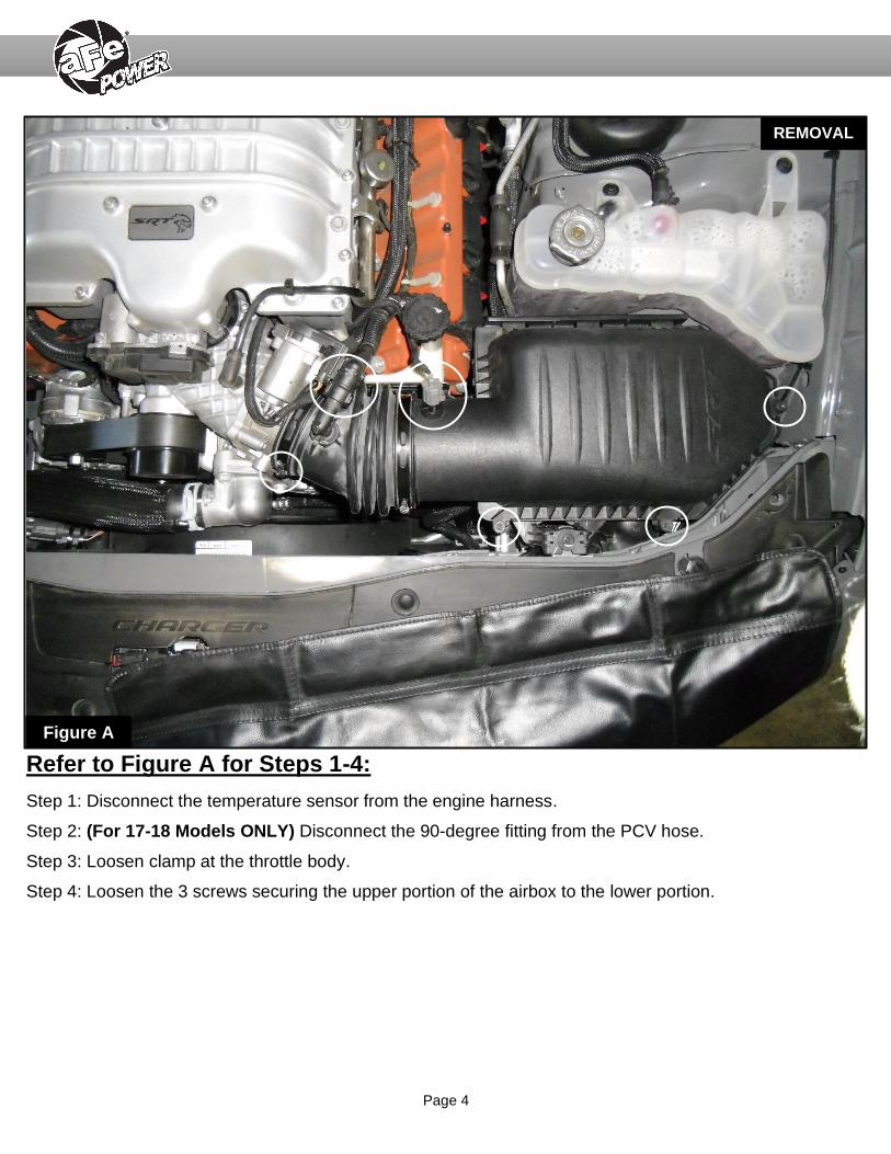
Refer to Figure A for Steps 1-4:
Step 1: Disconnect the temperature sensor from the engine harness.
Step 2: (For 17-18 Models ONLY) Disconnect the 90-degree fitting from the PCV hose.
Step 3: Loosen clamp at the throttle body.
Step 4: Loosen the 3 screws securing the upper portion of the airbox to the lower portion.
REMOVAL
Figure A

Page 5
Refer to Figure B for Steps 5-7:
Step 5: (For 19-20 models ONLY) Slice the plastic line connected to the MUA system. Try to make the cut
as clean as possible, if you ever need to reinstall the factory intake in the future. We suggest to use heat-
shrink sleeve to cover the cut if needed.
Step 6: (For 19-20 models ONLY) Disconnect the plastic hose from the MUA system. A silicone hose is
provided to connect the aFe POWER tube to the MUA system.
Step 7: Remove the upper portion of the factory airbox and the flat panel air filter.
REMOVAL
Figure B

Page 6
Refer to Figure C for Steps 8-10:
Step 8: Using an 8mm nut driver, remove the screw securing the factory airbox. This screw will be reused to
secure the aFe POWER housing.
Step 9: (For Challenger Models ONLY) Remove the lower part of the factory airbox and inlet duct as one
piece.
Step 10: (For Charger Models ONLY) Disconnect the inlet duct from the factory airbox and pull the lower
part of the airbox outside of the vehicle. (The inlet duct is not removable on Charger models)
Figure C
REMOVAL
Page 7
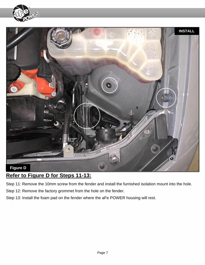
Refer to Figure D for Steps 11-13:
Step 11: Remove the 10mm screw from the fender and install the furnished isolation mount into the hole.
Step 12: Remove the factory grommet from the hole on the fender.
Step 13: Install the foam pad on the fender where the aFe POWER housing will rest.
INSTALL
Figure D
Page 8
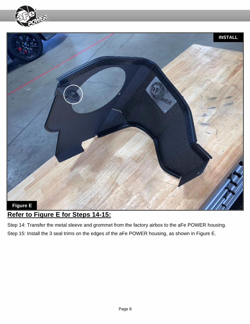
Refer to Figure E for Steps 14-15:
Step 14: Transfer the metal sleeve and grommet from the factory airbox to the aFe POWER housing.
Step 15: Install the 3 seal trims on the edges of the aFe POWER housing, as shown in Figure E.
INSTALL
Figure E

Page 9
Refer to Figure F for Step 16:
Step 16: Install the aFe POWER housing into the vehicle. Secure it with the factory screw removed at step 8
and also secure it to the isolation mount using the furnished M6 screw, lock washer, and flat washer.
INSTALL
Figure F
Page 10
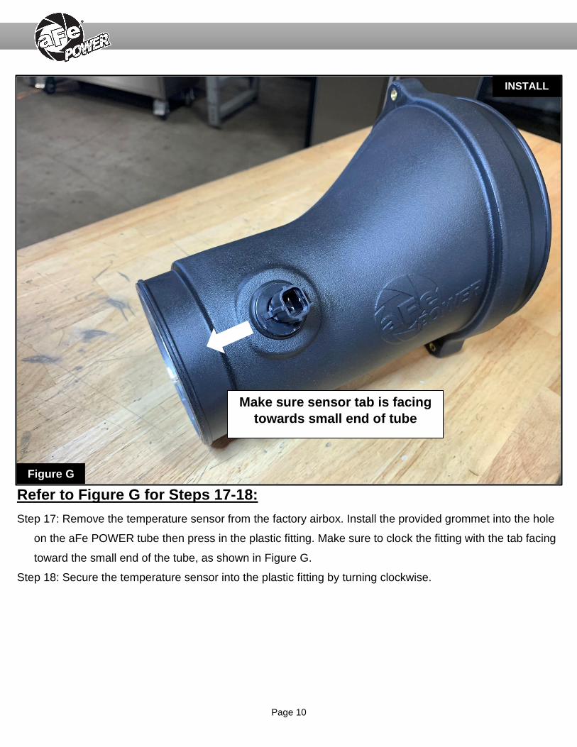
Refer to Figure G for Steps 17-18:
Step 17: Remove the temperature sensor from the factory airbox. Install the provided grommet into the hole
on the aFe POWER tube then press in the plastic fitting. Make sure to clock the fitting with the tab facing
toward the small end of the tube, as shown in Figure G.
Step 18: Secure the temperature sensor into the plastic fitting by turning clockwise.
INSTALL
Figure G
Make sure sensor tab is facing
towards small end of tube

Page 11
Refer to Figure H for Step 19:
Step 19: Install the coupling on the throttle body. Install the clamp closest to the throttle body only, do not
tighten clamp yet.
INSTALL
Figure H

Page 12
Refer to Figure I for Steps 20-24:
Step 20: Install the aFe POWER intake tube, by sliding the tube through the housing then into the coupling.
Step 21: Open the remaining T-bolt clamp and install it over the coupling and tube end.
Step 22: Secure the aFe POWER tube to the aFe POWER housing using the furnished M6 screws, lock
washers, and flat washer.
Step 23: Make sure the coupling, tube and air filter are aligned correctly, then tighten all clamps.
Step 24: Reconnect the temperature sensor harness.
INSTALL
Figure I
Page 13
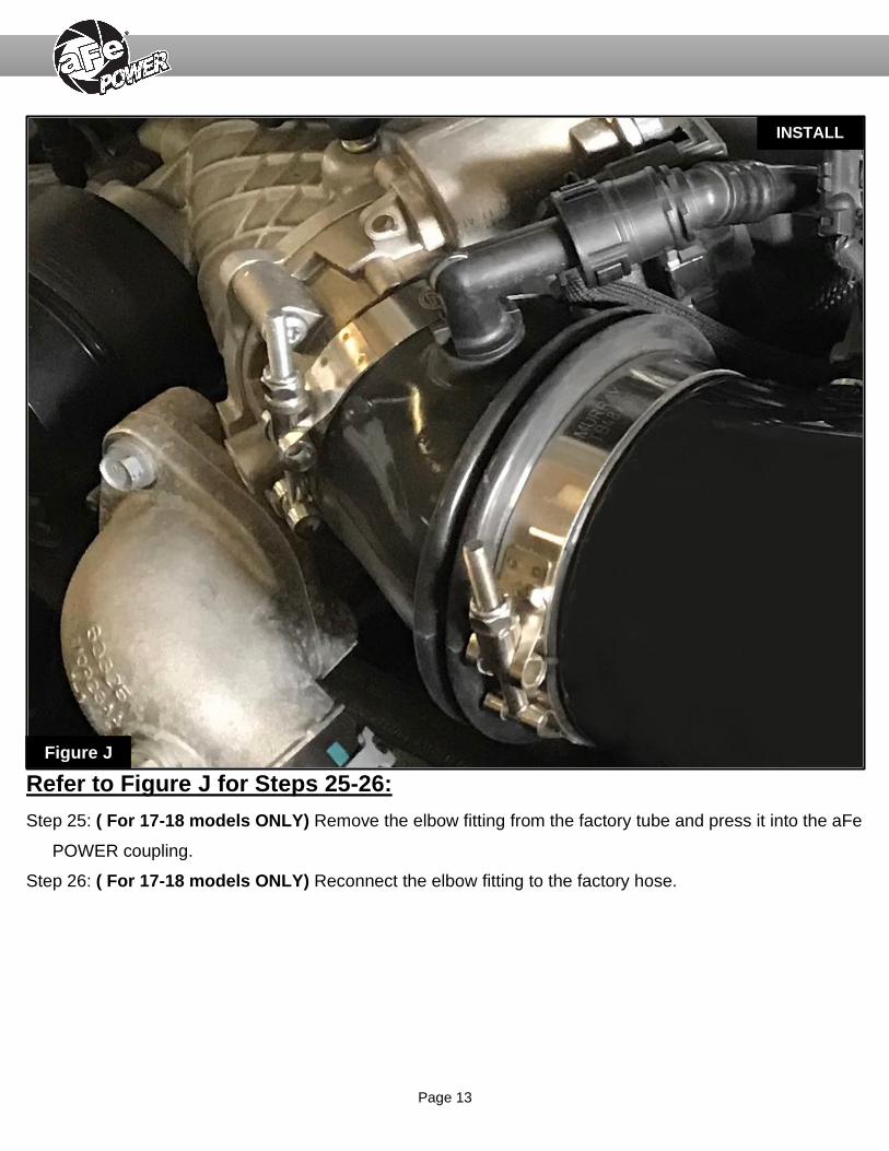
Refer to Figure J for Steps 25-26:
Step 25: ( For 17-18 models ONLY) Remove the elbow fitting from the factory tube and press it into the aFe
POWER coupling.
Step 26: ( For 17-18 models ONLY) Reconnect the elbow fitting to the factory hose.
INSTALL INSTALL
Figure J
Page 14
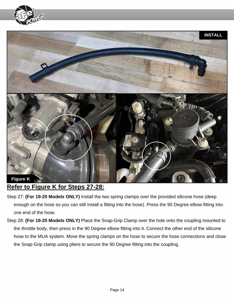
Refer to Figure K for Steps 27-28:
Step 27: (For 19-20 Models ONLY) Install the two spring clamps over the provided silicone hose (deep
enough on the hose so you can still install a fitting into the hose). Press the 90 Degree elbow fitting into
one end of the hose.
Step 28: (For 19-20 Models ONLY) Place the Snap-Grip Clamp over the hole onto the coupling mounted to
the throttle body, then press in the 90 Degree elbow fitting into it. Connect the other end of the silicone
hose to the MUA system. Move the spring clamps on the hose to secure the hose connections and close
the Snap-Grip clamp using pliers to secure the 90 Degree fitting into the coupling.
INSTALL INSTALL
Figure K
Page 15
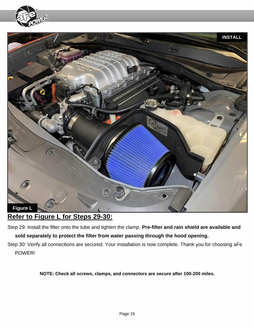
Refer to Figure L for Steps 29-30:
Step 29: Install the filter onto the tube and tighten the clamp. Pre-filter and rain shield are available and
sold separately to protect the filter from water passing through the hood opening.
Step 30: Verify all connections are secured. Your installation is now complete. Thank you for choosing aFe
POWER!
NOTE: Check all screws, clamps, and connectors are secure after 100-200 miles.
INSTALL
Figure L

Page 16
Page left blank intentionally

Page 17
Page left blank intentionally

Page 18
Pro DRY S Air Filter Pro 5R Air Filter Pro GUARD 7 Air Filter Pre-Filter
P/N: 21-91068 P/N: 24-91068 P/N: 72-91068 P/N: 28-10243
Blue Squeeze Restore Kit PRO DRY S Restore Kit Sprint Booster Challenger Sprint Booster Charger
P/N: 90-50501 P/N: 90-59999 P/N: 77-12002 P/N: 77-12009
Rain Shield Black Rain Shield Carbon Fiber Finish
P/N: 54-12808-B P/N: 54-12808-C
To purchase any of the items above, view airflow charts, dyno graphs, photos, and video; please go to aFepower.com.

Page 19
Warranty General Terms:
• aFe warrants their products to be free from manufacturer’s defects due to workmanship and material.
• This warranty applies only to the original purchaser of the product and is non-transferrable.
• Proof of purchase of the aFe product is required for all warranty claims.
• Warranty is valid provided aFe instructions for installation and/or cleaning were properly followed.
• Proper maintenance with regular inspections of product is required to insure warranty coverage.
• Damage due to improper installation, abuse, unauthorized repair or alteration is not warranted.
• Incidental or consequential damages or cost, including installation and removal of part, incurred due to failure of aFe product is not
covered under this warranty.
• All warranty is limited to the repair and/or replacement of the aFe part. To request Return Goods Authorization (“RGA”), email
[email protected] or call (951)493-7100. Upon receipt of the RGA, you must return the product to the address provided in the
RGA, freight prepaid and accompanied with a dated proof of purchase and the RGA. Upon receipt of the defective product and
upon verification of proof of purchase, aFe will either repair or replace the defective product within a reasonable time, not to exceed
thirty days.
Product Category P/N Prefix Warranty duration
Direct OE Replacement Filters 10, 11, 30, 31, 71, 73 Life of the vehicle
Racing Filters 18 1 year
Universal 20, 21, 23, 24, 72, TF 2 years
Air Intake Systems 50, 51, 53, 54, 55, 56, 57, 58, 75, TR, TA, TL, TM 2 years
Exhaust Systems 49 2 years
Intercoolers & Intercooler Tubes 46-2 2 years
Intake Manifolds 46-1 2 years
Differential Cover 46-7 Life of the vehicle
Exhaust Manifolds 46 2 years
Throttle Body Spacers 46-3 2 years
Turbochargers 46-6 2 years*
Fluid Filters 44 90 days
Pre-Filters 28 2 years
Heavy Duty OE Replacement 70 2 years
PowerSports OE Replacement 81, 87 2 years
PowerSports Intake Systems 85 2 years
No other warranty expressed or implied applies nor is any person or advanced FLOW engineering authorized to assume any other
warranty. Some States do not allow the exclusion or limitation of incidental or consequential damages or do not allow limitations on how
long an implied warranty lasts, so the above limitations or exclusions may not apply to you. This warranty gives you specific legal rights,
and you may also have other rights which vary from State to State.
*See turbocharger warranty for more info

252 Granite Street Corona, CA 92879 TEL: 951.493.7100 • TECH: 951.493.7185
E-Mail:[email protected] P/N: 06-81366