mak e-tiger® mounting instruction
TRANSCRIPT

BARTEC BENKE GmbH Schulstrasse 30 D-94239 Gotteszell Tel. +49(0)9929)-301-0 Fax +49(0)9929)-301-112 E-mail: [email protected] Internet: www.bartec-benke.de
MAK E-Tiger®
Mounting instruction
TB 180207

Mounting instruction, TB 180207

Mounting instruction, TB 180207
Contents Contents Page Issue date
1 Introduction _______________________________________ 1
2 Pipework _________________________________________ 2
3 System requirements _______________________________ 3
4 Measuring system __________________________________ 4 4.1 Piping diagram _____________________________________ 4 4.2 Measuring system layout _____________________________ 5 4.3 Ejector unit ________________________________________ 8 4.4 Suggested design for vacuum tank _____________________ 9 4.4.1 Suggested dimensions for vacuum tank ________________ 10 4.4.2 Dimensions of the measuring system with suggested design 11 4.5 Overview of pneumatic supply ________________________ 12 4.6 Pneumatic diagram _________________________________ 13 4.6.1 Information about the pneumatic system ________________ 14
5 Electrical installation ______________________________ 15 5.1 Overview plan _____________________________________ 15 5.2 Connection diagram for control cabinet _________________ 18 5.3 Terminal assignments in general ______________________ 21 5.3.1 Terminal assignment compact controller ________________ 21 5.3.2 Terminal assignment bottle drive ______________________ 22 5.3.3 Terminal assignment bottle drive mini __________________ 22 5.3.4 Terminal assignment bottle drive ABO __________________ 23 5.3.5 Terminal assignment bottle drive Schwarte Monotrans _____ 23
6 Technical data ____________________________________ 24 6.1 Three-dimensional representation Basic set _____________ 25
This document only defines details relevant to the way the equipment works with BARTEC MAK TIGER® measuring systems. It is the responsibility of the tanker and vehicle manufacturer to detail the wider design specification with regard to installation, service life and safety. All rights reserved and subject to change. Duplication, processing and distribution of this document or any part thereof is strictly subject to written consent from BARTEC BENKE. .
.
Copyright © 2018 by BARTEC BENKE
Schulstraße 30 D-94239 Gotteszell
Document / Version: TB 180207
Valid from / Author: 07.02.2018
Revised at/ by: 13.02.2018 K. Hacker


Introduction
1
Mounting instruction, TB 180207
1 Introduction The MAK E-TIGER® measuring system for milk tankers is designed for mo-bile use during milk collection. The measuring system can be operated entirely from an electrical source via a 16A CEE plug socket. It is the first self-priming measuring system to operate without gas separa-tors. The latest sensor technology measures the air portion which unavoidably occurs during intake and offsets it accordingly. This significantly increases the efficiency of the intake because the gas sep-arator with its limiting effect is not needed and the pumping output is in-creased. This new technology can only be fully exploited, however, if the design and build of the tanker meet certain basic specifications, so the tanker design engineer is crucial to the effective use of the system.
Note:
Several patents have been registered in relation to the measuring process.

Pipework
2
Mounting instruction, TB 180207
2 Pipework The MAK E-TIGER measuring system has an inlet and outlet with DN 80 (optionally DN 100) connections. The rest of the equipment is provided by the collection vehicle manufacturer. These auxiliary superstructures have a substantial influence on the perfor-mance of the milk collection vehicle. Some comments: If possible, avoid the following:
Changing the cross-sectional area
Sharp elbows
Right-angled outlets
T-pieces
Inward protruding welding seams
Rough internal surfaces in the pipework
Fittings projecting into the pipe
Anything which causes turbulence in the flow
Anything which impairs flow The inner diameter of the pipework, including the sampler and flow level me-ter, must always be at least 3 inches to avoid pressure drops, particularly on the intake side. To maximize the pump transfer rate, the pipework of the tank outlets, valve battery and pump transfer line must be at least DN 80. The pump transfer valve used by BARTEC BENKE is DN 80 (optionally DN 100) in compliance with DIN 11850. When assembling the measuring system, make particularly sure that the components are not under stress when installed. This can be achieved, for example, by decoupling the pipework with hose connections at suitable loca-tions. When attaching the components of the measuring system to different reference systems, they must be installed using flexible mountings (e.g. rub-ber dampers).

System requirements
3
Mounting instruction, TB 180207
3 System requirements For the MAK E-TIGER measuring system to operate at its optimum efficien-cy, it is essential that the design of the milk collection vehicle complies with the following boundary parameters:
The oils and antifreeze agents used in the pneumatic system (incl. compressor) must be safe for use in food production processes.
To guarantee the supply of compressed air, it must either be possible to start the vehicle remotely or an electrical auxiliary compressor must be installed.
A power supply of at least 16 A CEE must be ensured for the measuring system. To guarantee fault-free operation, we recommend using an all-current sensitive FI circuit breaker and a circuit breaker with C characteristic especially for motors.
The power supply wiring for the electronic components must be 2.5 mm2 csa. The operating voltage is 24V. A suitable voltage converter must be installed upstream for the 12V systems.
It must be possible to isolate the electronic components from the supply voltage via an all-pole main switch.
The measuring system cab must be heated in cooler weather.
If the ejector cannot be sufficiently heated using the cabin heating system, a heating sleeve must be provided.

Measuring system
4
Mounting instruction, TB 180207
4 Measuring system
4.1 Piping diagram

Measuring system
5
Mounting instruction, TB 180207
4.2 Measuring system layout In principle, all E-TIGER-measuring systems are of the same design (modu-lar). They only differ slightly in the arrangement of the inlets and outlets. The arrangement and organisation of the vacuum tank can be varied according to the customer's requirements. The vacuum tank is not included in the scope of supply of the E-TIGER. The vacuum tank must be organised so that it can be thoroughly cleaned in situ and so that it is not subject to over-suction (e.g. by partitioning plates, see Design suggestion under Point 4.4). The volume must be at least 60 li-tres and should preferably be too large rather than too small. The tank de-sign must comply with the Compressed Air Tank Directive 2009/105/EC. It is important for the vacuum tank to be able to empty itself at whatever an-gle the vehicle may take during intake. It is therefore mounted diagonally. The electric motor and the clutch housing of the pump must be protected with a suitable protective cover from milk or any Cleaning-In-Place (CIP) liq-uid running out of the valve battery. The pump and level container must be installed stress-free and vibration-damped. The basic dimensions of the measuring system arrangement must always be complied with. Measuring system basic set, front view

Measuring system
6
Mounting instruction, TB 180207
Measuring system basic set, side view

Measuring system
7
Mounting instruction, TB 180207
Measuring system basic set, plan view

Measuring system
8
Mounting instruction, TB 180207
4.3 Ejector unit

Measuring system
9
Mounting instruction, TB 180207
4.4 Suggested design for vacuum tank not included in the scope of supply from BARTEC BENKE
Note: - Vacuum tank mounted via vibration decoupling (rubber damper) - Cut the milk sensor 2 to a length of 15 cm and strip the rod approx. 3 cm.
Milk sensor 2
Partitioning panel
for the ejector via V3
Stress-free and pressure resistant connection (e.g. via hose piece)
Pressure sensor 1

Measuring system
10
Mounting instruction, TB 180207
4.4.1 Suggested dimensions for vacuum tank

Measuring system
11
Mounting instruction, TB 180207
4.4.2 Dimensions of the measuring system with suggested design
Measuring system
12
Mounting instruction, TB 180207
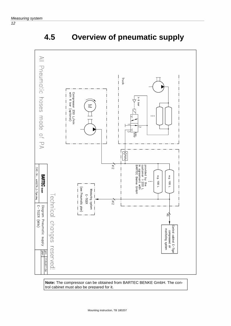
4.5 Overview of pneumatic supply
Note: The compressor can be obtained from BARTEC BENKE GmbH. The con-trol cabinet must also be prepared for it.

Measuring system
13
Mounting instruction, TB 180207
4.6 Pneumatic diagram BARTEC BENKE scope of delivery

Measuring system
14
Mounting instruction, TB 180207
4.6.1 Information about the pneumatic sys-tem In order to comply with food regulations, it is necessary to check the heavy-duty filter on component 292870 (air intake filter unit), to ensure proper drainage of condensate, and to check the contamination indicator for signs of discolouration once a week. Weekly checks are also required on the ejector control valve, the ejector and valves V3, V5 and V10 to ensure that they are all working correctly. This is simply done by vacuum testing. Any components showing abnormalities (heavy-duty filter, ejector, valves or control valve) must be replaced immediately! It is illegal to operate the system with defective components according to the food regulations. It is also essential to ensure that all the oils used in the pneumatic system and any additives which may get into it, including any antifreeze agents, are confirmed to be absolutely safe for use in food production processes and to be compliant with the relevant standards.

Electrical installation
15
Mounting instruction, TB 180207
5 Electrical installation
5.1 Overview plan
Electrical installation
16
Mounting instruction, TB 180207
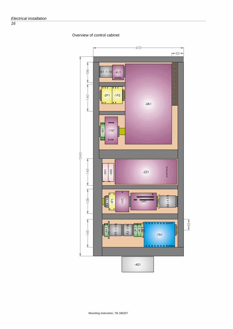
Overview of control cabinet

Electrical installation
17
Mounting instruction, TB 180207

Electrical installation
18
Mounting instruction, TB 180207
5.2 Connection diagram for control cabinet
BMK cable
Type Core N x Xmm² +earth +shield
Source Destination Comments
-W2 Ölfl.100 5x2.5 VDE0293f
Shield 5x2.5 mm² PE shield
-2Z1:PE -2M1:PE Electric motor connection cable
gnyl -2A1:PE -2M1:PE
bk -2Z1:L2' -2M1:V1
bl
br -2Z1:L1' -2M1:U1
bk -2Z1:L3' -2M1:W1
-W3 Ölflex-110 CY Shield 2x2.5 mm² shield -2A1:PE -2M1:PE Electric motor temperature moni-tor
1 -2A1:50 -2M1:
2 -2A1:53 -2M1:
-W4 Ölflex-110 CY Shield 2x2.5 mm² shield Shield/0V 24V supply from battery
1 -1F1:1 0V
2 -1F1:3 +24V
-W5 AW G20 24x0.5 AWG Metro
Shield 2x2.5 mm² shield -2A1:shield
bk -2A1:18 -X5:1
br -2A1:5 -X5:13
rd
or -2A1:29 -X5:3
yl -2A1:2 -X5:12
gn -2A1:6 -X5:5
bl -2A1:20 -X3:3
vl -2A1:54 -X5:6
gr -2A1:19 -X5:2
wt -2A1:33 -X3:2
wtbk
wtbr -2A1:55 -X5:7
wtrd -2A1:32 -X3:1
wtor
wtyl -2A1:3 -X5:4
wtgn -2A1:4 -X3:4
wtbl -2A1:20 -2K1:A2
wtvi
wtgr -2A1:27 -2K1:A1
brbk
brrd
bror
bryl
brgn
-W6 Ölflex-110 CY Shield 2x2.5 mm² shield -7A2:shield Supply for compact controller
1 -X3:10 -7A2:2
2 -X3:5 -7A2:1
-W101 Ölfl.100 2x0.75VDE0293ov/2
br 2x0.75 mm² -5A1:24 Solenoid valve for ejector
bl -5A1:25
-W102 Ölfl.100 2x0.75 VDE0293ov/2
br 2x0.75 mm² -5A1:26 Solenoid valve for discharge
bl -5A1:27
-W103 Valve terminal VM10 DIN47100
wt 25x0.5 mm² -5A1:28 Valve terminal connection cable

Electrical installation
19
Mounting instruction, TB 180207
br -5A1:30
gn -5A1:31
yl -5A1:32
gr -5A1:33
pk -5A1:34
bl -5A1:35
rd -5A1:44
bk -5A1:37
vi -5A1:38
grpk -5A1:36
rdbl -5A1:46
wtgn -5A1:29
brgn
wtyl
ylbr
wtgr
grbr
wtpk
pkbr
wtbl
brbl
wtrd
brrd
wtbk

Electrical installation
20
Mounting instruction, TB 180207
BMK ca-ble
Type Core N x Xmm² +earth +shield
source Destination Comments
-W104 LiYCY 10x0.25 DIN47100
Shield 10x2.5 mm² shield -7A2:shield PNET & power output from compact controller
wt -2K1:14 -7A2:31
br -7A1:S -7A2:73
gn -7A1:B -7A2:72
yl -7A1:A -7A2:71
gr
pk -2K1:13 -7A2:30
bl -7A1:- -7A2:74
rd -7A1:+ -7A2:70
bk -7A2:49 -X5:7
vi -7A2:48
-X5:6
-W105 AWG20 24x0.5 AWGMetro
Shield 24x2.5 mm² shield -7A2:shield Emergency mode com-pact controller
bk -5A1:19 -7A2:80
br -5A1:12 -7A2:20
rd -5A1:39 -7A2:78
or -5A1:16 -7A2:28
yl -5A1:14 -7A2:24
gn -5A1:13 -7A2:22
bl -5A1:17 -7A2:76
vi -5A1:20 -7A2:82
gr -5A1:15 -7A2:26
wt -5A1:11 -7A2:18
wtbk -5A1:41 -7A2:88
wtbr -5A1:10 -7A2:16
wtrd -5A1:18 -7A2:86
wtor -5A1:9 -7A2:14
wtyl
wtgn -5A1:3 -7A2:21
wtbl -5A1:5 -7A2:96
wtvi -5A1:4 -7A2:95
wtgr -5A1:3 -7A2:83
brbk -5A1:8 -7A2:41
brrd -5A1:6 -7A2:39
bror -5A1:7 -7A2:40
bryl -5A1:40 -7A2:84
brgn
-W106 LiYCY 7x0.25 DIN47100
Shield 7x0.25 mm² shield Milk sensor 3
pk -5A1:21
br
gn
yl
gr -5A1:22
wt
bl -5A1:23
-W107 Ölfl. 100 2x0.75 VDE 0293 ov/2
1 2
2x 0.75 mm² -x3:15 -x3 16
-651 -651
Thermostat for ejector heater
-W108 Ölflex 1 2
2x 1.5mm² -x3:17 -x3:14
-6E1:1 -6E1:2
Ejector heater

Electrical installation
21
Mounting instruction, TB 180207
5.3 Terminal assignments in general
5.3.1 Terminal assignment compact control-ler

Electrical installation
22
Mounting instruction, TB 180207
5.3.2 Terminal assignment bottle drive Bottle drive with pneumatic lift mechanism type 6774-10 Outputs Ultrasampler type 6771-31
Terminal Signal name Colour Connected to
25 26 27 28 29 30 31 32 33 34
+24 V on-board power supply, auxiliary supply for sensor system Digital input IN 1 Digital input IN 2 Digital input IN 3 Digital input IN 4 Digital input IN 5 Digital input IN 6, (bottle in position) Digital input IN 7, (star in position) Digital input IN 8, (bottle down) 0 V on-board power supply, reference ground for IN 1-8
bl Wire jumper pi/wt
As required As required As required As required As required As required Bottle drive P-Star (terminal 49) Bottle drive As required
42 43 44 45 46 47 48 49 50 51
Signal M-Up, bottle lifting motor Signal M-Down, bottle lifting motor Signal M-Out, magazine discharge motor Signal M-In, magazine infeed motor Signal M-Star, star drive motor Signal P-Star, self-holding contact for star drive Ground reference potential for P-Star signal Signal P-Star, check-back signal + 24 V on-board power supply for bottle drive GND on-board power supply for bottle drive Shield connection for bottle drive cable
bn rd yl gn pk vi grwt Wire jumper bk bnwt
IN 7 (terminal 32)
52 53
Shield connection for on-board power cable + 24V on-board power supply GND on-board power supply
Vehicle battery+ Vehicle battery-
54 55 56
+ 24V on-board power output OGND on-board power output + 44 V operating voltage output for sampler 1
rd 1.5 mm² bl 1.5 mm² bk 1.5 mm²
Terminal 39, sampler circuit board Terminal 40, sampler circuit board Terminal 41, sampler circuit board
5.3.3 Terminal assignment bottle drive mini Bottle drive mini, type 6774-12 Outputs for Ultrasampler type 6771-31
Terminal phy. log. inv. Function
6 1
7 2 82 Bottle UP/DOWN
8 3 83 PBL transport
9 4 84 Magnetic plate motor (via relay)
10 Reference ground for OUT 1-4
11 5
12 6
13 7
14 8
15 Reference ground for OUT 5-8

Electrical installation
23
Mounting instruction, TB 180207
5.3.4 Terminal assignment bottle drive ABO Outputs for Ultrasampler type 6771-31
Terminal phy. log. inv. Function
6 1 81 Clamp OPEN/CLOSE
7 2 82 Clamp UP/DOWN
8 3 83 PBL transport
9 4 84 Magnetic plate motor
10 Reference ground for OUT 1-4
11 5
12 6
13 7
14 8
15 Reference ground for OUT 5-8
5.3.5 Terminal assignment bottle drive Schwarte Monotrans Outputs for Ultrasampler type 6771-31
Terminal phy. log. inv. Function
6 1
7 2 82 Lower fill head
8 3 83 PBL transport
9 4 84 Magnetic plate motor (via relay)
10 Reference ground for OUT 1-4
11 5
12 6
13 7
14 8
15 Reference ground for OUT 5-8

Technical data
24
Mounting instruction, TB 180207
6 Technical data
Data specific to measuring system
Voltage rating for electronics DC 24V (9 - 36V) on-board power supply (load-dump protection, sta-bilised)
Operating voltage measuring sys-tem
AC 400V, 16 A CEE
Power connection AC 400V, 16 A CEE plug, 3L+PE 6h
Emergency mode On-board power supply 24V (valves), 16 A CEE three-phase AC (cen-trifugal pump)
Drive 7.5 kW IE3 electric motor, frequency inverter controlled
Speed approx.. 2000 rpm
Self-supply electronics in pump-ing mode
DC 24V, max. 10 A
Control cabinet heater DC 24V; 150 W
Compressor (optional) 250 l/min at 6 bar; max. 10 bar
Compressed air ejector 5.6 bar (service unit)
Valve terminal 6 bar (service unit)
Compressed air level 4 bar filter 0.01 µ
Air consumption ejector approx. 500 nl/min @ 5.6 bar
Suction power typical 1300 l/min. with good intake conditions, max. 2000 l/min transfer pumping
Connections level container DN 80 (optionally DN 100) clamp for transfer pumping and suction
Accuracy ≤ 0.5 %
Lowest intake rate 100 l at 3” MID, optional 50 l at 2.5” MID
CIP yes; max. 85°C @ 2 bar
Mechanical data
Material of milk line V2A; PTFE; PEEK; POM
Dimensions See scale drawing
Weight Approx. 230 kg
Ambient conditions
Operating temperature 0 to + 85°C medium; - 20 to + 50°C electronics
(frequency inverter required for cold start < 0°C a heat-up time)
Storage temperature - 20 to + 60°C (without fluid)
Protection class for measuring system
IP 55
Protection class for control cabi-net
IP 55

Technical data
25
Mounting instruction, TB 180207
6.1 Three-dimensional representation Basic set

Mounting instruction, TB 180207
***