maintenance system for electric bicycles - panasonic
TRANSCRIPT

Before use, please read this Service guide carefully.© Panasonic Cycle Technology Co., Ltd. 2014
Service guideMAINTENANCE SYSTEM FOR ELECTRIC BICYCLES
Centre driving unitENGLISH
For Dealers

2(D ENG)
ContentsBefore starting use ....................................................... 3
Caution .................................................................................. 3Precautions for use ............................................................... 3Trademarks and licenses ...................................................... 3
Outline ........................................................................... 4Introduction ........................................................................... 4Compatible model ................................................................. 4Operating environment.......................................................... 4Connection diagram .............................................................. 4
Installing the Application ............................................. 5Operation Methods ....................................................... 7
Flow of operations ................................................................. 7Connection Method ............................................................... 8Start-up method .................................................................. 10Explanation of main screen ................................................. 12Diagnosing the drive unit..................................................... 13Delete error ......................................................................... 14Saving diagnostic results .................................................... 15Clearing diagnostic results .................................................. 15Reading diagnostic results .................................................. 15Printing diagnostic results ................................................... 16Starting up the mailer .......................................................... 17Electric bicycles system update .......................................... 17Maintenance System update............................................... 18Updating the connection to the electric bicycles ................. 18
Settings ....................................................................... 19Flow of operations ............................................................... 19Starting up the setting screen ............................................. 19Setting the diagnostic results save directory ....................... 20Print settings ....................................................................... 21Network settings.................................................................. 21Language settings ............................................................... 21
[Console] screen ........................................................ 22Flow of operations ............................................................... 22[Console] screen ................................................................. 22[Settings] tab ....................................................................... 24[Operation check] tab .......................................................... 25
[Control unit (Motor unit)] screen ............................. 26Flow of operations ............................................................... 26
[Battery] screen .......................................................... 29Flow of operations ............................................................... 29[Battery] screen ................................................................... 29[Device info] tab .................................................................. 30
Other ............................................................................ 30Version information display ................................................. 30How to exit the application .................................................. 30
Diagnostic results list ................................................ 31[Console] diagnostic results list ........................................... 31[Control unit (Motor unit)] diagnostic results list .................. 33[Battery] diagnostic results list............................................. 36

3(D ENG)
Before starting useCaution
Keep the USB authentication key out of reach of infants.Accidentally swallowing it may cause injuries. ●Seek the advice of a doctor immediately if it has been swallowed.
Precautions for useOperation cannot be guaranteed under the following usage scenarios as there is the possibility of malfunction.
●If multiple Micro USB cables are connected to a single PC ●If the USB authentication key or Micro USB cable are handled with wet hands ●If a cable other than the dedicated Micro USB cable is used ●If a damaged USB authentication key or Micro USB cable is used
Trademarks and licenses ●Microsoft, Windows and Windows Vista are either registered trademarks or trademarks of Microsoft Corporation in the United States and/or other countries. ●Microsoft product screen shot(s) reprinted with permission from Microsoft Corporation. ●Intel® is a trademark of Intel Corporation in the United States and other countries. ●Other names, company names, and product names mentioned in these instructions are trademarks or registered trademarks of the companies concerned. ●Unauthorised reproduction of this software is prohibited.
4(D ENG)
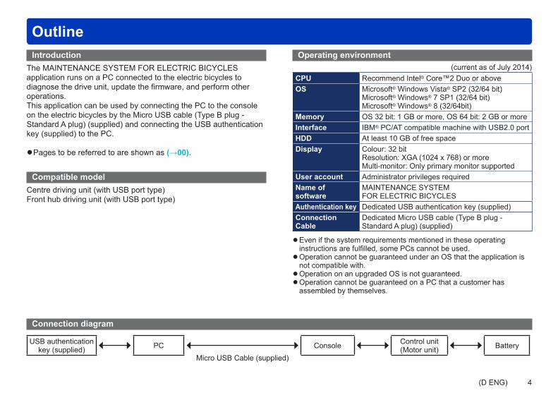
OutlineIntroduction
The MAINTENANCE SYSTEM FOR ELECTRIC BICYCLES application runs on a PC connected to the electric bicycles to diagnose the drive unit, update the firmware, and perform other operations.This application can be used by connecting the PC to the console on the electric bicycles by the Micro USB cable (Type B plug - Standard A plug) (supplied) and connecting the USB authentication key (supplied) to the PC.
●Pages to be referred to are shown as (→00).
Compatible modelCentre driving unit (with USB port type)Front hub driving unit (with USB port type)
Connection diagram
USB authentication key (supplied) PC Console Control unit
(Motor unit) BatteryMicro USB Cable (supplied)
Operating environment(current as of July 2014)
CPU Recommend Intel® Core™2 Duo or aboveOS Microsoft® Windows Vista® SP2 (32/64 bit)
Microsoft® Windows® 7 SP1 (32/64 bit)Microsoft® Windows® 8 (32/64bit)
Memory OS 32 bit: 1 GB or more, OS 64 bit: 2 GB or moreInterface IBM® PC/AT compatible machine with USB2.0 portHDD At least 10 GB of free spaceDisplay Colour: 32 bit
Resolution: XGA (1024 x 768) or moreMulti-monitor: Only primary monitor supported
User account Administrator privileges requiredName of software
MAINTENANCE SYSTEM FOR ELECTRIC BICYCLES
Authentication key Dedicated USB authentication key (supplied)Connection Cable
Dedicated Micro USB cable (Type B plug - Standard A plug) (supplied)
●Even if the system requirements mentioned in these operating instructions are fulfilled, some PCs cannot be used. ●Operation cannot be guaranteed under an OS that the application is not compatible with. ●Operation on an upgraded OS is not guaranteed. ●Operation cannot be guaranteed on a PC that a customer has assembled by themselves.
5(D ENG)
Installing the Application
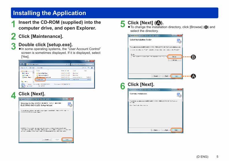
1 Insert the CD-ROM (supplied) into the computer drive, and open Explorer.
2 Click [Maintenance].
3 Double click [setup.exe]. ●In some operating systems, the “User Account Control” screen is sometimes displayed. If it is displayed, select [Yes].
4 Click [Next].
5 Click [Next] ( A ). ●To change the installation directory, click [Browse] ( B ) and select the directory.
B
A
6 Click [Next].

6(D ENG)
Installing the Application
7 Click [Next].
8 When accepting the licensing agreement for the first time, select [I accept this agreement] ( C ), and click [Next] ( D ).
CD
9 Click [Finish].
10This completes installation. When the following screen is displayed, click [Close].

7(D ENG)
Operation MethodsFlow of operations
Diagram - Flow of operations
Connect the bicycle to the PC
Turn the console on
Start-up the application Main screen Start
diagnosis
[Console] screen
[Control unit (Motor unit)] screen
[Battery] screen
Update
Electric bicycles system update
Maintenance System update
Settings
Tips ●The console screen, control unit screen (motor unit) and battery screen run by starting up diagnostics. ●The Maintenance System update is run automatically when the application is started up.

8(D ENG)
Operation Methods
1 Install with the display unit aligned with the concave and convex sections of the cradle.
2 Open the rubber cap on the bottom of the display unit.
3 Connect the PC to the display unit by the Micro USB cable (supplied), and press the power button on the display unit.
RequestsAlways close the cap of the USB authentication key and rubber cap of the display unit after exiting the application.
Connection Method Centre LCD type connection method
9(D ENG)
Operation Methods
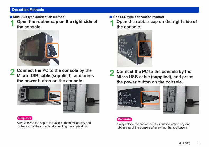
Side LCD type connection method
1 Open the rubber cap on the right side of the console.
2 Connect the PC to the console by the Micro USB cable (supplied), and press the power button on the console.
RequestsAlways close the cap of the USB authentication key and rubber cap of the console after exiting the application.
Side LED type connection method
1 Open the rubber cap on the right side of the console.
2 Connect the PC to the console by the Micro USB cable (supplied), and press the power button on the console.
RequestsAlways close the cap of the USB authentication key and rubber cap of the console after exiting the application.
10(D ENG)
Operation Methods
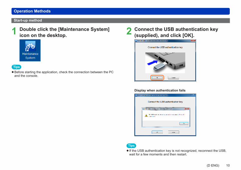
1 Double click the [Maintenance System] icon on the desktop.
Tips ●Before starting the application, check the connection between the PC and the console.
Start-up method
2 Connect the USB authentication key (supplied), and click [OK].
Display when authentication fails
Tips ● If the USB authentication key is not recognized, reconnect the USB, wait for a few moments and then restart.
11(D ENG)
Operation Methods
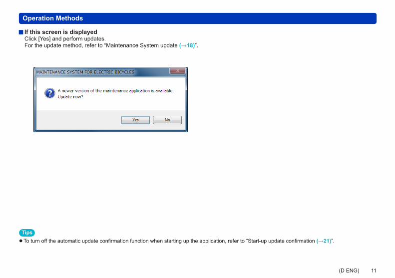
If this screen is displayedClick [Yes] and perform updates. For the update method, refer to “Maintenance System update (→18)”.
Tips ●To turn off the automatic update confirmation function when starting up the application, refer to “Start-up update confirmation (→21)”.
12(D ENG)
Operation Methods
A B C D
A9 A10 A11 A12 A13 A14A6 A7 A8
A2A1
A3
A4
A5
E F G
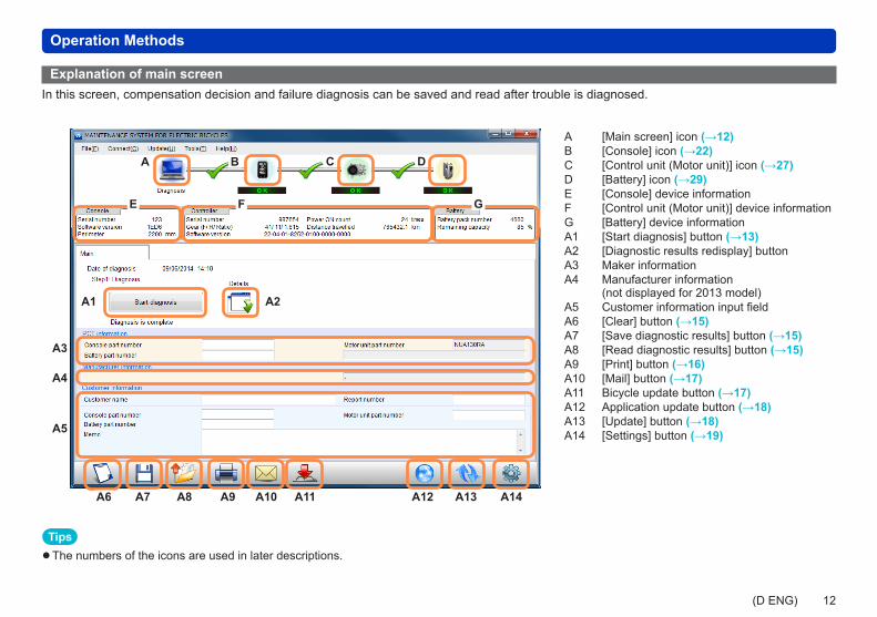
Explanation of main screenIn this screen, compensation decision and failure diagnosis can be saved and read after trouble is diagnosed.
A [Main screen] icon (→12)B [Console] icon (→22)C [Control unit (Motor unit)] icon (→27)D [Battery] icon (→29)E [Console] device informationF [Control unit (Motor unit)] device informationG [Battery] device informationA1 [Start diagnosis] button (→13)A2 [Diagnostic results redisplay] buttonA3 Maker informationA4 Manufacturer information
(not displayed for 2013 model)A5 Customer information input fieldA6 [Clear] button (→15)A7 [Save diagnostic results] button (→15)A8 [Read diagnostic results] button (→15)A9 [Print] button (→16)A10 [Mail] button (→17)A11 Bicycle update button (→17)A12 Application update button (→18)A13 [Update] button (→18)A14 [Settings] button (→19)
Tips ●The numbers of the icons are used in later descriptions.

13(D ENG)
Operation Methods
Diagnosing the drive unitDiagnose trouble on the drive unit.
Click the [Start diagnosis](A1) button. ●Diagnosis can also be performed by selecting [Tools] → [Diagnosis] on the menu. ●Failure diagnosis results can be checked again by clicking the [ ] (A2).
Diagnosis result ●[OK] is displayed if the diagnostic result is normal. ●[ERROR], [CHECK] or [WARNING] is displayed if judgment ends in error.
For details, refer to “Diagnostic results list (→31)”.
14(D ENG)
Operation Methods
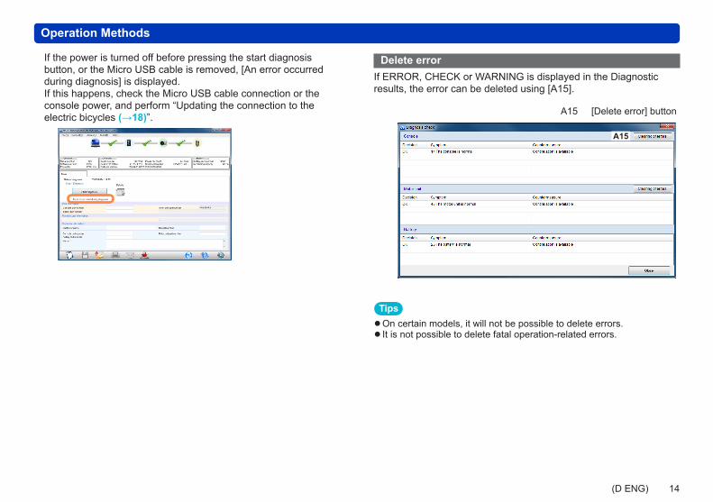
If the power is turned off before pressing the start diagnosis button, or the Micro USB cable is removed, [An error occurred during diagnosis] is displayed. If this happens, check the Micro USB cable connection or the console power, and perform “Updating the connection to the electric bicycles (→18)”.
Delete errorIf ERROR, CHECK or WARNING is displayed in the Diagnostic results, the error can be deleted using [A15].
A15 [Delete error] button
A15
Tips ●On certain models, it will not be possible to delete errors. ● It is not possible to delete fatal operation-related errors.
15(D ENG)
Operation Methods
Saving diagnostic results
1 Click [ ] (A7). ●Diagnostic results can also be saved by selecting [File] → [Save diagnostic results] on the menu.
2 Click [OK] to save. ●To change the save directory, refer to “Setting the diagnostic results save directory (→20)”.
Clearing diagnostic results
Click [ ] (A6) to clear the entire display.
Reading diagnostic results
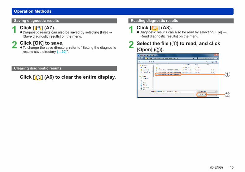
1 Click [ ] (A8). ●Diagnostic results can also be read by selecting [File] → [Read diagnostic results] on the menu.
2 Select the file ( 1 ) to read, and click [Open] ( 2 ).
2
1

16(D ENG)
Operation Methods
1 Click [ ] (A9). ●Diagnostic results can also be printed by selecting [File] → [Print] on the menu.
2 When the print details screen is displayed, set the print format, and click [OK].
3 Details will be printed as follows.Entered details will be printed in positions with the same corresponding number.
Customer details entry box at bottom of main screen
12
357
8
46
Settings screen (Print)
9
10
11
Printing diagnostic resultsPrinted results (shared)
1
3
4
910
11
5
27
6
8
17(D ENG)
Operation Methods
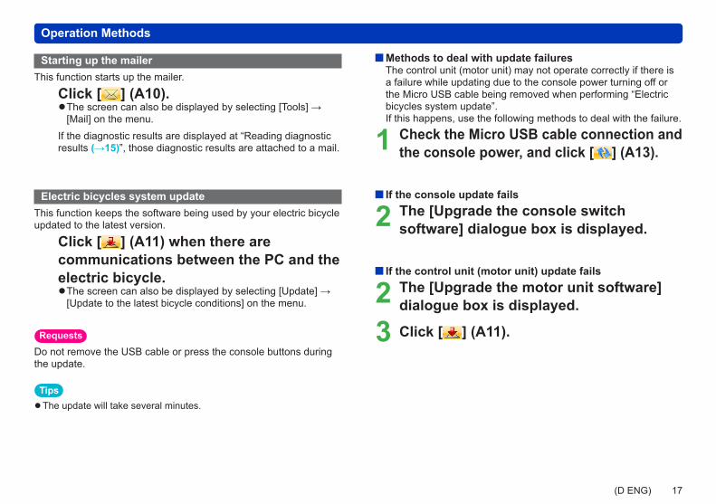
Starting up the mailerThis function starts up the mailer.
Click [ ] (A10). ●The screen can also be displayed by selecting [Tools] → [Mail] on the menu.
If the diagnostic results are displayed at “Reading diagnostic results (→15)”, those diagnostic results are attached to a mail.
Electric bicycles system updateThis function keeps the software being used by your electric bicycle updated to the latest version.
Click [ ] (A11) when there are communications between the PC and the electric bicycle.
●The screen can also be displayed by selecting [Update] → [Update to the latest bicycle conditions] on the menu.
RequestsDo not remove the USB cable or press the console buttons during the update.
Tips ●The update will take several minutes.
Methods to deal with update failuresThe control unit (motor unit) may not operate correctly if there is a failure while updating due to the console power turning off or the Micro USB cable being removed when performing “Electric bicycles system update”.If this happens, use the following methods to deal with the failure.
1 Check the Micro USB cable connection and the console power, and click [ ] (A13).
If the console update fails
2 The [Upgrade the console switch software] dialogue box is displayed.
If the control unit (motor unit) update fails
2 The [Upgrade the motor unit software] dialogue box is displayed.
3 Click [ ] (A11).

18(D ENG)
Operation Methods
Maintenance System updateThis function connects to the internet and keeps the application updated to the latest version.
1 Click [ ] (A12). ●Updates can also be checked by selecting [Update] → [Diagnosis software update] from the menu bar.
2 Click [Yes] if updates can be performed.
3 The update is started.
Tips ●Use a PC in an area where the internet can be used.
Updating the connection to the electric bicyclesThis function is for performing failure diagnosis continuously.
Connect the console to be failure-diagnosed next to the PC, and click [ ] (A13).
●The connection can also be made by selecting [Connect] → [Reconnect] on the menu.
Tips ●Do not connect the console of two or more bicycles to the PC. ●The screen can also be updated with the F5 key.
When the connection is successfully made, [ ] is displayed.In this state, diagnostics and other various functions can be used.
19(D ENG)
SettingsFlow of operations
Diagram - Flow of operations in setting screen
Main screen Settings Setting the diagnostic results save directory
Print settings
Network settings
Language settings
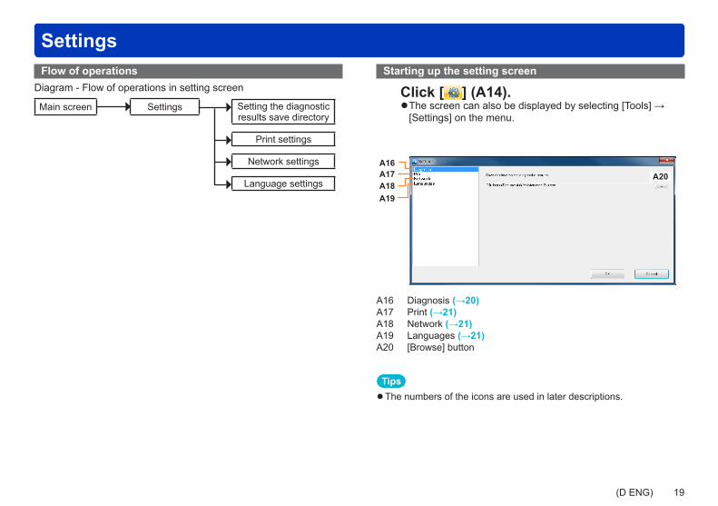
Starting up the setting screen
Click [ ] (A14). ●The screen can also be displayed by selecting [Tools] → [Settings] on the menu.
A16A20A17
A18A19
A16 Diagnosis (→20)A17 Print (→21)A18 Network (→21)A19 Languages (→21)A20 [Browse] button
Tips ●The numbers of the icons are used in later descriptions.
20(D ENG)
Settings
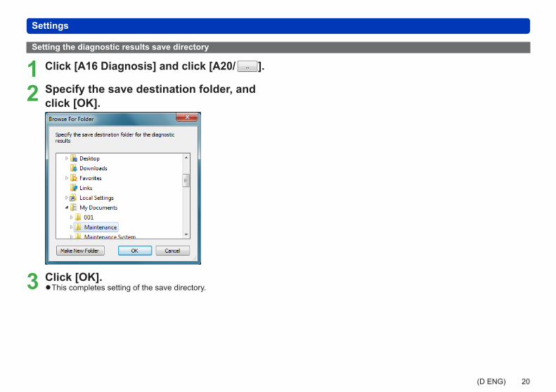
Setting the diagnostic results save directory
1 Click [A16 Diagnosis] and click [A20/ ].
2 Specify the save destination folder, and click [OK].
3 Click [OK]. ●This completes setting of the save directory.

21(D ENG)
Settings
Print settings
Click [A17 Print]. ●Only single-byte alphanumeric characters can be entered.
Network settings Proxy settings
Click [A18 Network] to change the proxy settings.
Requests ●Change this setting only if a proxy server is used. ●This should be run by the system administrator.
Start-up update confirmationDeselect the [A21 Check for software updates on startup] checkbox if you do not want Maintenance System updates to be checked when the system starts up.
A21
Language settings
1 Click [A19 Languages].
2 Select a language from the list on the right.
3 Click [OK]. ●Restarting the application completes setting of the language.

22(D ENG)
B
B2 B3
B4
B1
[Console] screenFlow of operations
Diagram - Flow of operations in console screen
Main screen Console screen [Device info] tab Firmware update
[Settings] tab Parameter rewriting
[Operation check] tab Switch test
Tips ●Before entering the console screen, perform failure diagnosis. ●The [Settings] tab is not displayed for the side LED switch.
[Console] screenIn this screen, the console can be updated, the settings changed and the operation checked.
B [Console] iconB1 [Device info] tabB2 [Settings] tabB3 [Operation check] tabB4 [Console firmware update] button
Tips ●The displayed content may differ depending on the model. ●The numbers of the icons are used in later descriptions.
23(D ENG)
[Console] screen
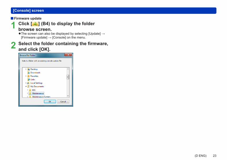
Firmware update
1 Click [ ] (B4) to display the folder browse screen.
●The screen can also be displayed by selecting [Update] → [Firmware update] → [Console] on the menu.
2 Select the folder containing the firmware, and click [OK].

24(D ENG)
[Console] screen
How to rewrite console dataSelect the item to rewrite from the [B5 Selection of rewrite item], set a value using [B6 Setup parameters], and click [B7 Write].
Tips ●The rewritable portion is displayed in red. ●The numbers of the icons are used in later descriptions.
[Settings] tabThe [Settings] tab is not displayed for the side LED switch.
Click [B2 Settings].
B6
B7
B5
B5 Selection of rewrite itemB6 Setup parametersB7 [Write] button

25(D ENG)
[Console] screen
[Operation check] tab
3 Check items currently displayed in the dialogue box in the console screen.
4 Click [OK].
If the Diagnostic results are normal the lamp lights up in green.
If the Diagnostic results are abnormal the lamp lights up in red.
Click [B3 Operation check].
Switch testTest to see if there are any abnormalities in console buttons and display.
1 Click [Switch test].
2 Press the switch on the main unit corresponding to the switch that is flashing in orange.
●If the switch is successfully recognised, the switch test item is displayed in green. If it is not successfully recognised, the item lights up in red.
In the following cases, the item lights up in red and the system moves on to the next test.
●The wrong switch is pressed 3 times ●No switch is pressed for 5 seconds

26(D ENG)
[Control unit (Motor unit)] screenFlow of operations
Diagram - Flow of operations in control unit (motor unit) screen
Main screen Control unit (Motor unit) screen [Device info] tab Write in parameter
Firmware update
Deauthorising
Delete travel log
Tips ●Before entering the control unit (motor unit) screen, perform failure diagnosis. ●The displayed content may differ depending on the model.
27(D ENG)
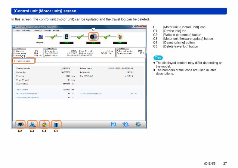
[Control unit (Motor unit)] screen
C
C1
C2 C3 C4 C5
In this screen, the control unit (motor unit) can be updated and the travel log can be deleted.
C [Motor unit (Control unit)] iconC1 [Device info] tabC2 [Write in parameter] buttonC3 [Motor unit firmware update] buttonC4 [Deauthorising] buttonC5 [Delete travel log] button
Tips ●The displayed content may differ depending on the model. ●The numbers of the icons are used in later descriptions.

28(D ENG)
[Control unit (Motor unit)] screen
How to rewrite control unit (motor unit) parameters
Click [ ] (C2), select an frm file, and click [Open].
How to update the control unit (motor unit)Click [ ] (C3), and select the folder containing the firmware and click [OK].
How to deauthorise the console and control unit (motor unit)
Click [ ] (C4).
●This function is not currently available.
Delete travel log
Click [ ] (C5).
Restore travel log to factory default settings.

29(D ENG)
D
D1
D2
[Battery] screenFlow of operations
Diagram - Flow of operations in battery screen
Main screen Battery screen [Device info] tab LED lit
Tips ●Before entering the battery screen, perform failure diagnosis.
D [Battery] iconD1 [Device info] tabD2 [The battery LED lights up] button
Tips ●The numbers of the icons are used in later descriptions.
[Battery] screen
30(D ENG)
[Battery] screen
[Device info] tab
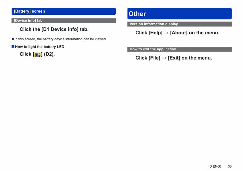
Click the [D1 Device info] tab.
●In this screen, the battery device information can be viewed.
How to light the battery LED
Click [ ] (D2).
OtherVersion information display
Click [Help] → [About] on the menu.
How to exit the application
Click [File] → [Exit] on the menu.
31(D ENG)
Diagnostic results listThis is a detailed list of diagnostic results displayed at “Diagnosing the drive unit (→13)”.
[Console] diagnostic results list
Judgment Symptom CountermeasureERROR 1. Failed to update the firmware 1. Update the console software again using the maintenance application
2. Replace the consoleERROR 2. An internal failure has occurred in the console Replace the consoleERROR 3. A past internal failure has been detected in the console Replace the consoleERROR 4. An authentication error has occurred between the
console and the motor unit(Centre LCD switch)
1. Check the motor unit for a malfunction2. Check the connection cable between the console and the motor unit3. Check for dirt on the cradle contact or the display unit contact4. Check the combination of the display unit and the motor unit
(If the display unit has been replaced, perform the authentication reset process)
5. Replace the consoleERROR 4. An authentication error has occurred between the
console and the motor unit(Other than centre LCD switch)
1. Check the motor unit for a malfunction2. Check the connection cable between the console and the motor unit3. Replace the console
ERROR 5. A communication error has occurred between the console and the motor unit
(Centre LCD switch)
1. Check the connection cable between the console and the motor unit2. Check for dirt on the cradle contact or the display unit contact3. Replace the console
ERROR 5. A communication error has occurred between the console and the motor unit
(Other than centre LCD switch)
1. Check the connection cable between the console and the motor unit2. Replace the console
ERROR 6. The DD switch button is pushed or there is a short circuit in the DD switch
1. Check that the DD switch is not pushed, and cycle the power2. Replace the console
CHECK 7. The button battery is dead 1. Replace the button battery, and configure the clock settings2. Replace the console
CHECK 8. Average speed calculation has failed Reset the odometer
32(D ENG)
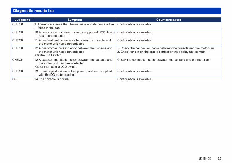
Diagnostic results list
Judgment Symptom CountermeasureCHECK 9. There is evidence that the software update process has
failed in the pastContinuation is available
CHECK 10. A past connection error for an unsupported USB device has been detected
Continuation is available
CHECK 11. A past authentication error between the console and the motor unit has been detected
Continuation is available
CHECK 12. A past communication error between the console and the motor unit has been detected
(Centre LCD switch)
1. Check the connection cable between the console and the motor unit2. Check for dirt on the cradle contact or the display unit contact
CHECK 12. A past communication error between the console and the motor unit has been detected
(Other than centre LCD switch)
Check the connection cable between the console and the motor unit
CHECK 13. There is past evidence that power has been supplied with the DD button pushed
Continuation is available
OK 14. The console is normal Continuation is available

33(D ENG)
Diagnostic results list
[Control unit (Motor unit)] diagnostic results list
Judgment Symptom CountermeasureERROR 1. A communication failure with the motor unit has
occurred1. Check the connection cable between the console and the motor unit2. Replace the motor unit or the console
ERROR 2. There is a problem with the firmware 1. Update the firmware again2. Replace the motor unit
WARNING 2. There is a problem with the firmware 1. Update the firmware againWARNING 2. There is a problem with the firmware 1. Update the firmware againERROR 3. Abnormalities in the setting values of the motor unit
have occurredReplace the motor unit
ERROR 4. Abnormalities in the setting values of the motor unit have occurred
Replace the motor unit
ERROR 5. Torque sensor failure has occurred Replace the motor unitERROR 6. Torque sensor failure has occurred Replace the motor unitERROR 7. Torque sensor failure has occurred Replace the motor unitERROR 8. Failure of the motor unit rotation sensor has occurred Replace the motor unitERROR 9. A circuit failure has occurred Replace the motor unitERROR 10. A circuit failure has occurred Replace the motor unitERROR 11. A failure has occurred in the temperature detection
componentReplace the motor unit
ERROR 12. A failure has occurred in the temperature detection component
Replace the motor unit
ERROR 13. Abnormalities in the setting values of the motor unit have occurred
Replace the motor unit
ERROR 14. Torque sensor failure has occurred Replace the motor unitERROR 15. Torque sensor failure has occurred Replace the motor unitERROR 16. Torque sensor failure has occurred Replace the motor unitERROR 17. Failure of the motor unit rotation sensor has occurred Replace the motor unitERROR 18. A circuit failure has occurred Replace the motor unit

34(D ENG)
Diagnostic results list
Judgment Symptom CountermeasureERROR 19. A circuit failure has occurred Replace the motor unitERROR 20. A circuit failure has occurred Replace the motor unitCHECK 21. Torque sensor failure has occurred 1. Do not step on the pedal when turning the power ON
2. Replace the motor unitCHECK 22. Torque sensor failure has occurred 1. Do not step on the pedal when turning the power ON
2. Replace the motor unitCHECK 23. An authentication error has occurred between the
battery and the motor unit1. Check the battery connection cable2. Replace the battery3. Replace the motor unit
CHECK 24. An communication error has occurred between the battery and the motor unit
1. Check the battery connection cable2. Replace the battery3. Replace the motor unit
CHECK 25. A communication error has occurred between the console and the motor unit
1. Check the console connection cable2. Replace the console
CHECK 26. A communication error has occurred between the speed sensor and the motor unit
1. Check the speed sensor connection cable2. Replace the speed sensor
CHECK 27. A past authentication error between the battery and the motor unit has been detected
Continuation is available
CHECK 28. A past communication error between the battery and the motor unit has been detected
Continuation is available
CHECK 29. The motor unit has reached the temperature limit in the past
Continuation is available
CHECK 30. The motor unit has reached the temperature limit in the past
Continuation is available
CHECK 31. The battery has reached the temperature limit in the past
Continuation is available
CHECK 32. The battery has reached the temperature limit in the past
Continuation is available
CHECK 33. A past communication error between the console and the motor unit has been detected
Continuation is available

35(D ENG)
Diagnostic results list
Judgment Symptom CountermeasureCHECK 34. A past communication error between the speed sensor
and the motor unit has been detectedContinuation is available
WARNING 35. A past short circuit in the switch wiring has been detected
Continuation is available
WARNING 36. A past malfunction in the crank rotation sensor has been detected
Continuation is available
WARNING 37. The battery voltage is low Continuation is availableWARNING 38. The battery voltage is low Continuation is availableWARNING 39. There is evidence that the power has been turned ON
while the pedal was being stepped on in the pastWithout stepping on the pedal, push the power button and supply power
OK 40. The motor unit is normal Continuation is availableWARNING 44. Failed to process the vehicle settings Process the manufacturer’s vehicle settings again
36(D ENG)
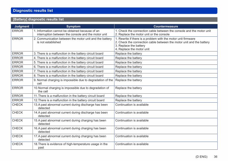
Diagnostic results list
[Battery] diagnostic results list
Judgment Symptom CountermeasureERROR 1. Information cannot be obtained because of an
interruption between the console and the motor unit1. Check the connection cable between the console and the motor unit2. Replace the motor unit or the console
ERROR 2. Communication between the motor unit and the battery is not established
1. Rewrite if there is a problem with the motor unit firmware2. Check the connection cable between the motor unit and the battery3. Replace the battery4. Replace the motor unit
ERROR 3. There is a malfunction in the battery circuit board Replace the batteryERROR 4. There is a malfunction in the battery circuit board Replace the batteryERROR 5. There is a malfunction in the battery circuit board Replace the batteryERROR 6. There is a malfunction in the battery circuit board Replace the batteryERROR 7. There is a malfunction in the battery circuit board Replace the batteryERROR 8. There is a malfunction in the battery circuit board Replace the batteryERROR 9. Normal charging is impossible due to degradation of the
cellReplace the battery
ERROR 10. Normal charging is impossible due to degradation of the cell
Replace the battery
ERROR 11. There is a malfunction in the battery circuit board Replace the batteryERROR 12. There is a malfunction in the battery circuit board Replace the batteryCHECK 13. A past abnormal current during discharge has been
detectedContinuation is available
CHECK 14. A past abnormal current during discharge has been detected
Continuation is available
CHECK 15. A past abnormal current during charging has been detected
Continuation is available
CHECK 16. A past abnormal current during charging has been detected
Continuation is available
CHECK 17. A past abnormal current during charging has been detected
Continuation is available
CHECK 18. There is evidence of high-temperature usage in the past
Continuation is available

37(D ENG)
Diagnostic results list
Judgment Symptom CountermeasureCHECK 19. There is evidence of high-temperature usage in the
pastContinuation is available
CHECK 20. There is evidence of high-temperature usage in the past
Continuation is available
CHECK 21. A past authentication failure with the charger has been detected
Continuation is available
CHECK 22. There is evidence of high-temperature (low-temperature) usage in the past
Continuation is available
OK 23. The battery is normal Continuation is availableOK 24. The battery is normal Continuation is availableOK 25. The battery is normal Continuation is available
NYT1525M0714-0
See the package for contact detailsManufactured by: Panasonic Cycle Technology Co., Ltd.