maintenance manual mm-18114 mtc-3118-fv (tc-180) transfer … · the mtc-3118-fv (tc-180) is a...
TRANSCRIPT

Meritor MTC3118FV / Fabco TC-180 Transfer Case Service Manual
Pro Gear Meritor MTC3118FV / Fabco TC-180 Transfer Case Service Manual to assist in identifying your Meritor / Fabco unit.
If you need any assistance identifying the correct transfer case unit for your truck and equipment, contact your Meritor / Fabco replacement part specialists at Pro Gear and Transmission.
Pro Gear Transmission has same day shipping and 1000’s of products in stock and ready to ship internationally for your next project.
For parts or service contact the Meritor / Fabco specialists at Pro Gear & Transmission, Inc.
1 (877) 776-4600 (407) [email protected]
,
~~ ,~ ., ... -
• ' ,!
i .. ; ~ ~ ;,::;;--~ - ~•?:'.-
Maintenance Manual MM-18114
MTC-3118-FV (TC-180) Transfer CaseIssued 09-18
~MERITOR

Service Notes
Information contained in this publication was in effect at the time the publication was approved for printing and is subject to change without notice or liability. Meritor Heavy Vehicle Systems, LLC, reserves the right to revise the information presented or to discontinue the production of parts described at any time.
Meritor Maintenance Manual MM-18114 (Issued 09-18)
About This ManualThis manual provides service and repair procedures for Meritor MTC-3118-FV (TC-180) transfer cases.
Before You Begin1. Read and understand all instructions and procedures before
you begin to service components.
2. Read and observe all Warning and Caution hazard alertmessages in this publication. They provide information that canhelp prevent serious personal injury, damage to components,or both.
3. Follow your company’s maintenance and service, installation,and diagnostics guidelines.
4. Use special tools when required to help avoid serious personalinjury and damage to components.
Hazard Alert Messages and Torque Symbols
WARNINGA Warning alerts you to an instruction or procedure that you must follow exactly to avoid serious personal injury and damage to components.
CAUTIONA Caution alerts you to an instruction or procedure that you must follow exactly to avoid damage to components.
@ This symbol alerts you to tighten fasteners to a specified torque value.
How to Obtain Additional Maintenance, Service and Product InformationVisit Literature on Demand at meritor.com to access and order additional information.
Contact the Meritor OnTrac™ Customer Call Center at 866-668-7221 (United States and Canada); 001-800-889-1834(Mexico); or email [email protected].
If Tools and Supplies are Specified in This ManualContact Meritor’s Commercial Vehicle Aftermarket at 888-725-9355.
A
A

pg. pg.
Contents
1 Section 1: IntroductionDescriptionMTC-3118-FV (TC-180) Transfer Case and Split Shaft PTO
2 Assembly Views
5 Section 2: LubricationRecommended LubricantsInspectionOil ChangeDraining the OilRefilling the OilOperating Temperature
6 Section 3: Cleaning and InspectionCleaningDry and Corrosion InhibitionInspection
7 Section 4: General InstructionsSafetyAssembly PrecautionsRemoval
8 Installation
9 Section 5: DisassemblyDisassemblyGeneral DisassemblyTransfer Case Component Removal
10 PTO Shaft Removal11 Input Shaft Removal
Rear Output Shaft Removal12 Front Output Shaft Removal13 Intermediate Shaft Removal14 Subassemblies
Input shaft Disassembly15 Intermediate Shaft Disassembly
Front Output and PTO Shaft Disassembly16 Rear Output Shaft Disassembly without Neutral17 Rear Output Shaft Disassembly with Neutral18 Shift Shaft Disassembly (PTO and Front Output)
20 Section 6: AssemblyAssemblyAssembly of SubassembliesAssembly of the Input Shaft
21 Assembly of the Intermediate ShaftAssembly of the Front Output and PTO Shaft
23 Assembly of the Rear Output with Neutral and Carrier27 General Assembly — Intermediate Shaft Installation29 Rear Output Shaft Installation30 Front Output and PTO Shaft Installation
33 Input Shaft Installation
35 Section 7: Torque SpecificationsTorque Specifications
38 Section 8: Seal Installation InstructionsSeal Installation Instructions
40 Section 9: ToolsTool Drawings

1 Introduction
1Meritor Maintenance Manual MM-18114 (Issued 09-18)
1 IntroductionDescription
MTC-3118-FV (TC-180) Transfer Case and Split Shaft PTOThe MTC-3118-FV (TC-180) is a family of transfer case and split shift power take offs with single-speed, three-shaft, constant mesh design. The new model MTC-3118-FV (TC-180) is the latest generation design replacing the model 170 and 175. The MTC-3118-FV (TC-180) features increased oil capacity, higher strength main housing, increased torque capacity helical gearing, ultra-high temperature seals and gaskets, revised declutching gearing and a proprietary lubrication pump, yet retains the same installation envelope of previous designs.
* All ratings nomical. Actual capacities determined based uponreview of application data by Meritor Engineering.
Ratings — Nominal*
—Torque 15,000 Lb-Ft
18,000 Lb-Ft (Through Shaft
—Horsepower 600 HP
—Input Speed 3,000 RPM
Ratio 1:1 Standard, Contact Mertior for Optional Ratios
Gear Type Helical, Case Hardened
Shaft Sizes
—Input/Front and Rear Output
2.50 Inches, 10 Parallel Spline
Shaft Spacing (Drop) 16.25 Inches
Shift Mechanism Integral Air Cylinders
Bearings Tapered Roller
Lubrication System Pressurized and Splash
Lubricant SAE 50 or 75W90 GL4 MT-1 Synthetic Gear Oil
Oil Capacity, Nominal 12.0 Quarts
Weight, Dry 470 Lbs. approximately
Housing Precision Cast
0

1 Introduction
2 Meritor Maintenance Manual MM-18114 (Issued 09-18)
Assembly Views
Figure 1.1
Figure 1.1
4014148a
MTC-MTC3118-FV (TC-180) TRANSFER CASE AND SPLIT SHAFT PTO
0
ew high stre ngth precision cast housing. Ho sing has thicker
section I enhanced material properties and revised -geometry
to give maximum durabil i y_ Lifting bosses, hydraulic pump support bosses and oil II hoe
'" "'" .. "'""" ~ New coarse-pil ch, high streng h
forged helical gearing gives increased torque & horsepower
capacity while retain ing qu·et performance .
Compatib le with commercial available drive yokes & ilanges.
Re ·secr declutch gear tooth profile thro ghoul
for op imized shi 'ing performance.
Available, - h a large range of PTO and SJI.E pump pad / -""~"'
Retains same mo nting-pattem and drive shaft spacing as the popular Faboo Model 170 &
175, ma ing cuslomer integralion easy.
Faboo proprietary oil p mp lo r imp roved
service pertom1ance_ Military in- heatre proven
design.
Improved lubrication distribution al crili ca I
shaft bearings_
Larger oil sump fo r improved lubrication.

1 Introduction
3Meritor Maintenance Manual MM-18114 (Issued 09-18)
Figure 1.2
Figure 1.2
MTC-3118-FV (TC-180) SECTIONAL VIEW
FRONT < OUPUT
INPUT
REAR . > OUTPUT
0

1 Introduction
4 Meritor Maintenance Manual MM-18114 (Issued 09-18)
Figure 1.3
Figure 1.3
MTC-3118-FV (TC-180) WITH UPPER REAR PTO — SECTIONAL VIEW
4014150a
FRONT
AXLE
0
,.,.._. ______ _,,.., REAR
AXLE )
PTO OUTPUT

2 Lubrication
5Meritor Maintenance Manual MM-18114 (Issued 09-18)
2 LubricationRecommended LubricantsSAE 50 synthetic is recommended for on/off-highway operation.
InspectionThe oil is to be maintained at the level of the fill plug at all times. Check at the following intervals:
Highway Service – 1,000 Miles
Off-Highway Service – 40 Hours
With every oil change, the shift cylinder air lines and valves should be inspected for leaks and possible malfunctioning. Low pressure conditions can cause partial clutch engagement which may result in premature wear or damage.
Oil ChangeThe transfer case lubricant should be changed on all new transfer cases after the first 3,000 to 5,000 miles (on-highway), or the first 40 hours (off-highway); thereafter oil changes should be done at the following intervals:
Highway Service – 10,000-15,000 Miles
Off-Highway Service – 500-700 Hours
The recommended oil change and inspection periods are based on average use and operating conditions that the unit may encounter. It is suggested that the individual owner make a periodic lab analysis of the lubricant to determine contamination based on the units specific operating conditions. With this data, the oil change and inspection periods can be better determined
Draining the OilDraining is best accomplished after the vehicle has been operated briefly, allowing the oil to become warm and flow more freely. Remove both drain and fill plugs. Allow the housing to empty completely. Before the unit is refilled, it should be thoroughly flushed with clean flushing oil or kerosene.
The lube oil filter should be replaced whenever the oil is changed. The filter element is of a spin-on type. A film of clean oil should be applied to the rubber gasket of the new filter element before installing. Do not over tighten.
Refilling the OilIf the transfer case has been removed from the vehicle for service, it is the best to refill the oil after the unit has been reinstalled into the vehicle.
Clean and replace the drain plug and fill the transfer case with the appropriate oil with the vehicle on level ground. Fill the transfer case to the level of the sight glass
Operating TemperatureThe operating temperature of the transfer case should not exceed 250°F (120°C). Extensive operation at temperatures exceeding 250°F will result in rapid brake down of the oil and may shorten the transfer case life. If reduction of operating speeds is not acceptable then the case may have to be equipped with external oil cooler to maintain the operating temperature below 250°F.
The following conditions may contribute to excessive oil temperatures:
1. A vehicle which is used in tropical or desert conditions.
2. A vehicle where extended body work or an accumulation of dirt and plant material may shield the case from air ventilation and circulation.
3. A vehicle that is operated for extended distances at high speed with the main transmission in overdrive.
NOTE: EXTREME PRESSURE (EP) OILS ARE NO LONGER RECOMMENDED FOR USE IN MERITOR TRANSFER CASES. UNDER CERTAIN OPERATING CONDITIONS THESE OILS MIGHT FORM CARBON DEPOSITS ON GEARS AND SHAFTS.
0

3 Cleaning and Inspection
6 Meritor Maintenance Manual MM-18114 (Issued 09-18)
3 Cleaning and InspectionCleaningSteam may be used for external cleaning of completely assembled units. Care must be taken to ensure that water is kept out of the assembly by sealing breather caps and other openings.
The transfer case housing which, is too large to conveniently clean with solvents, may be immersed in a hot solution tank containing a mild alkaline solution. Aluminum parts such as the carriers, caps, declutch housing, and air shift cylinder components must never be cleaned in any type of alkaline solution. Parts clean in a hot solution tank must be rinsed thoroughly to prevent damage by traces of alkaline material.
Parts with ground or polished surfaces, such as bearings, gears, shafts, and oil pump components should be clean with emulsion cleaners or petroleum solvents. An alkaline solution may damage the machined surfaces and such cleaning methods should be avoided.
Dry and Corrosion InhibitionDry compressed air or clean, soft shop towels should be used to dry parts after cleaning. Bearings should never be spun dry with compressed air.
Dried parts should be immediately coated with a light oil or corrosion inhibitor to prevent corrosion damage. Parts which are to be stored should also be wrapped in heavy waxed paper or plastic bags and kept dust-free.
InspectionPrior to reassembly, parts which are to be reused must be carefully inspected for signs of wear or damage. Replacement of such parts can prevent costly downtime at a future date.
All bearing surfaces, including roller bearings cups and cones, should be examined for pitting, wear, or overheating. Gears may also show pits, as well as scoring and broken teeth. Shafts may be nicked or marked, or have damage threads. Parts which show any signs of damage should be repaired or replaced.
Inspect the oil pump. If any damage is noted, the pump assembly should be replaced as a unit.
Check all shift forks and slots in sliding clutches for wear or discoloration due to heat. Check the engaging teeth for a partial engagement wear pattern.
0

4 General Instructions
7Meritor Maintenance Manual MM-18114 (Issued 09-18)
4 General InstructionsSafetyThe servicing and maintenance of components from any automotive vehicle present possible hazards, every endeavor should be made to minimize the risk taken to successfully complete the task. For your protection we offer these warnings and suggestions.
1. When working on, around, or under the vehicle the parkingbrake should be securely applied and all wheels should beblocked to prevent wheel movement. Do not rely on the vehiclebeing in gear with a dead engine to prevent movement. Allwork should be performed on a flat level surface free of loosematerial.
2. When working under a vehicle, it should be raised andsupported with the appropriate frame stands or very secureblocking.
WARNINGNever work under a vehicle while supported only on a floor jack or hoist.
3. Be sure any lifting equipment has adequate capacity to raisethe vehicle or component being lifted. This includes hydraulicfloor jacks, and axle support dollies, etc. The weight ofcomponents is given in the front of the applicable servicemanual.
4. Caution must be exercised when cleaning the component orunderside of the vehicle. Compressed air should not be used toblow dirt away as any harmful contaminant material on thebottom of the vehicle will be spread around the work area
Appropriate solvents and cleaning solutions can be used inaccordance with their labeling instructions or by referring to the Material Safety Data Sheet (MSDS) that is available for eachcleaner. Approved protective eyewear, gloves, masks, andclothing should always be worn.
Assembly Precautions1. Read these instructions completely before starting reassemble.
Refer to the appropriate exploded view in the parts manual.
2. All parts must be cleaned. The gasket surfaces must be free ofoil gasket material. Do not reuse old gaskets.
3. Bearing cups bores, shaft splines and bearing mountingsurface, should be coated with Lubriplate or equivalent. This isnecessary to reduce the possibility of galling.
4. All used oil seals must be replaced and the new oil sealsshould be coated with Loctite 601 or equivalent on their outerdiameter prior to being installed in their bores. The sealing lipsshould be coated with Lubriplate or the equivalent to provideinitial lubrication.
5. All external cap screw should have there threads coated withloctite.
6. All threaded fasteners should be tightened to the torquespecified in the torque specification section.
7. Any sharp edges on the seal diameter of the universal jointyoke or companion flanges should be removed with emerycloth and should be coated with Lubriplate or the equivalent onthe seal operating area prior to installation
8. In many of the procedures, when a part is assembled with apress fit, it is recommended that the part be heated prior toinstallation. The part should be placed in an oven and heated to no more that 300°F. Excessive heat my change themetallurgical properties of the part. Heated components shouldbe allowed to cool to room temperature before end floatmeasurements are made.
CAUTIONAlthough Meritor does not recommend its use in transfer cases, if formed in place gasket is used for repairs, extreme caution must be exercised to prevent compound from entering bearings, oil galleries, and passages or tapped holes. All beads must be kept smaller than 1/8-inch diameter.
Removal1. Remove fill and lower drain plugs and drain gear lubricant.
2. Disconnect wire leading to indicator light switch andtemperature sensor, if used.
3. Disconnect and tag shift cylinder air lines.
4. Disconnect speedometer cable.
5. Disconnect drivelines at flanges or yokes.
6. Position a transmission jack of suitable capacity beneath thetransfer case. The transfer case must be seated on the jack ina safe and firm position.
7. Disconnect transfer case mounting at the rubber shockinsulators. Since mounting designs vary, consult the vehicleservice manual.
A
A
0

4 General Instructions
8 Meritor Maintenance Manual MM-18114 (Issued 09-18)
8. After making sure that all mounting and connections to thetransfer case are disconnected, lower the transfer casegradually to the floor. It is imperative that the transfer case isALWAYS safely positioned on the transmission jack tosafeguard the transfer case from falling off the jack. Removethe transfer case from beneath the vehicle. It may benecessary to jack the truck up to allow room to remove thetransfer case.
Installation1. Place the transfer case onto the transmission jack, preferably
lifting by means of the eye bolts.
2. Position the transmission jack underneath the vehicle. Somevehicles may require that one side be jacked up in order toachieve sufficient clearance to place the transfer case betweenthe frame rails.
3. Raise the transmission jack to properly locate the transfercase.
4. Connect transfer case mounting. Since mounting designs vary, consult vehicle service manual.
5. Connect the drivelines, the speedometer cable, and the shiftcylinder air lines.
6. Connect the indicator light and temperature sensor wires.
7. Fill the housing with the appropriate lubrication to the correctlevel and install the oil fill plug.
8. Road test the vehicle and check the transfer case for leaksaround seals and gaskets.
0

5 Disassembly
9Meritor Maintenance Manual MM-18114 (Issued 09-18)
5 DisassemblyDisassemblyDisassembly and assembly of the Meritor MTC-3118-FV (TC-180) transfer case with PTO is a relatively simple procedure which can be made easier by the use of some very simple tooling. Details of all tooling required are given in the tooling section (9.0) for manufacture in your own facilities or Meritor may be contacted for a price and availability.
General Disassembly1. After removing the transfer case from the vehicle, thoroughly
clean the exterior.
2. Remove the drain plug and drain the oil.
3. Mount the transfer case in a suitable fixture. The fixture shouldbe such that the case can be rotated so that either its front orits rear is facing upward. A transfer case mounted in a typicalfixture is shown in Figure 5.1.
Figure 5.1
4. Remove the oil pump assembly, and gasket.
Transfer Case Component RemovalFor purposes of this manual, a MTC-3118-FV (TC-180) with PTO contains five shaft assemblies: Input, Intermediate, Front Output, Rear Output, and PTO shaft assembly.
Be sure to use the correct procedure for each shaft assembly. In some procedures, a similar procedure for a different shaft is called out.
1. Remove oil strainer. Figure 5.2.
Figure 5.2
2. Remove the four hoses. Remove oil filter from the oil filterbracket. Figure 5.3.
Figure 5.3
3. Remove the four bolts securing the filter bracket, then the filterbracket itself. Figure 5.4.
Figure 5.1
4014151a
Figure 5.2
Figure 5.3
4014152a
4014153a
0

5 Disassembly
10 Meritor Maintenance Manual MM-18114 (Issued 09-18)
Figure 5.4
4. Remove the three indictor light switches and washers locatedon the front side of the transfer case attached to the housingon the FRONT OUPUT SHAFT, the transfer case’s back side onthe declutch housing, and the rear output carrier. Figure 5.5.
Figure 5.5
5. Remove the three switch actuating pins with a pencil magnet.Figure 5.6.
Figure 5.6
6. Refer to the procedure in this section for removal of the air shiftcylinders from the declutch housings.
PTO Shaft Removal
Figure 5.7
To remove the PTO shaft assembly and declutch housing, refer to the the Front Output Shaft Removal procedure for similar instructions.
Figure 5.4
Figure 5.5
4014154a
4014155a
Figure 5.6
Figure 5.7
4014156a
4014157a
0

5 Disassembly
11Meritor Maintenance Manual MM-18114 (Issued 09-18)
Input Shaft Removal
Figure 5.8
1. If PTO declutch housing or cap has been removed, also removeshim pack on rear side. Keep the shims together with the PTOdeclutch housing or cap to facilitate reassembly.
2. Carefully rotate the TC over so that the front side is facingupward. The input shaft can slide downwards as it has someplay between the housing and the gear, and it is only held bythe bearing cup that is no longer constraint by the PTOdeclutch housing or cap.
3. Remove the ten capscrews and washers securing the frontinput carrier to the housing.
4. Remove the input carrier and shaft assembly by lifting on theshaft yoke. Discard the gasket.
Rear Output Shaft Removal
Figure 5.9
1. Position the transfer case with its rear end facing upward.
2. Remove the ten cap screws and washers securing the rearoutput carrier to the transfer case housing.
3. Mark the position of the carrier to housing with chalk as itneeds to be reassembled in the same position.
4. Remove the carrier and shaft assembly by lifting on the shaftyoke. Discard the gasket. Figure 5.10.
Figure 5.10
Figure 5.8
4014158a
Figure 5.9
Figure 5.10
4014159a
4014160a
0
5 Disassembly
12 Meritor Maintenance Manual MM-18114 (Issued 09-18)
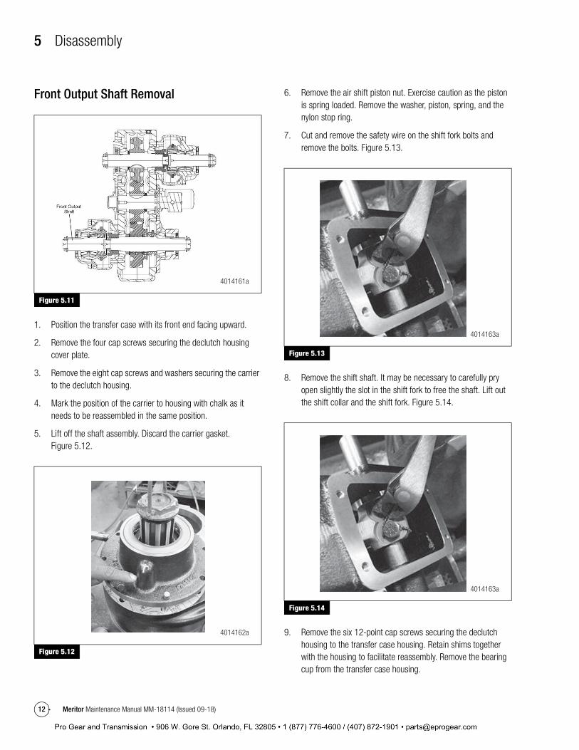
Front Output Shaft Removal
Figure 5.11
1. Position the transfer case with its front end facing upward.
2. Remove the four cap screws securing the declutch housingcover plate.
3. Remove the eight cap screws and washers securing the carrierto the declutch housing.
4. Mark the position of the carrier to housing with chalk as itneeds to be reassembled in the same position.
5. Lift off the shaft assembly. Discard the carrier gasket.Figure 5.12.
Figure 5.12
6. Remove the air shift piston nut. Exercise caution as the pistonis spring loaded. Remove the washer, piston, spring, and thenylon stop ring.
7. Cut and remove the safety wire on the shift fork bolts andremove the bolts. Figure 5.13.
Figure 5.13
8. Remove the shift shaft. It may be necessary to carefully pryopen slightly the slot in the shift fork to free the shaft. Lift outthe shift collar and the shift fork. Figure 5.14.
Figure 5.14
9. Remove the six 12-point cap screws securing the declutchhousing to the transfer case housing. Retain shims togetherwith the housing to facilitate reassembly. Remove the bearingcup from the transfer case housing.
Figure 5.11
Figure 5.12
4014161a
4014162a
Figure 5.13
Figure 5.14
4014163a
4014163a
0

5 Disassembly
13Meritor Maintenance Manual MM-18114 (Issued 09-18)
10. Do not remove the freeze plug from the shift shaft bore in thedeclutch housing unless necessary.
Intermediate Shaft Removal
Figure 5.15
On models not equipped with a lubrication pump, begin the procedure at Step 4.
1. Position the transfer case with its rear end facing upward.
2. Remove the four cap screws and washers securing the oilpump and remove it. Discard the gasket
3. Remove six cap screws securing the intermediate shaft cap.Remove cap. Figure 5.16.
Figure 5.16
4. Position the transfer case with its front end facing upward
5. Remove the six cap screws and washers securing the frontintermediate cap. Remove the cap and discard the gasket.
6. Remove the front bearing cup by pulling upwards on theintermediate shaft assembly.
7. The gear and the rear bearing cone both have a press fit to theintermediate shaft. Therefore, a puller will be necessary toremove the shaft if damage is to be avoided. (A sketchdepicting a suitable fabricated puller is illustrated inFigure 5.17.
Figure 5.17
8. To prevent damage, do not allow the bearing cone assembly orthe gear to drop inside the case as the shaft is being pulledout. Remove the shaft, gear, spacer, and bearing coneassembly.
9. Rotate the transfer case over so that its rear end is facingupward.
10. Remove the six cap screws and washers securing the rear capto the transfer case. Remove the cap, shim pack, and rearbearing cup. Keep the shims together with the cap to facilitatereassembly.
This concludes the general disassembly.
Figure 5.15
Figure 5.16
4014165a
4014166a
Figure 5.17
4014167a
0

5 Disassembly
14 Meritor Maintenance Manual MM-18114 (Issued 09-18)
SubassembliesDuring a normal overhaul, it is neither necessary nor desirable to completely disassemble the shaft assemblies. The bearing cone assemblies and the drive train gears are installed with a press fit to the shaft and their unnecessary removal only increases the likelihood of damage. The same applies to the bearing cups installed in the carriers.
Parts should be cleaned with emulsion cleaners or petroleum solvents. To avoid damage, alkaline solutions should not be used.
Input shaft Disassembly
Figure 5.18
1. Remove the input yoke (or companion flange) retaining locknutwith an impact wrench. Slide off the clutch gear if provided onthe rear side. Slide the input yoke (or flange) off the shaft onthe input side.
2. Lift off the input carrier assembly. Remove the oil seal from thecarrier and discard. Remove the bearing cup from the carrieronly if it is to be replaced. It is not necessary to disassemblethe shaft assembly any further unless one or more of thecomponents remaining are to be replaced.
3. Place the shaft assembly in a press so that the rear of the gearis supported and the press arbor bears against the threadedend of the shaft. Figure 5.19. Remove the front bearing coneassembly, the spacer washer, and the gear.
Figure 5.19
4. To remove the rear bearing cone assembly, support under thecone with a bearing separator and press the shaft through thecone. Figure 5.20. Remove the shaft key only if necessary
Figure 5.20
Figure 5.18
4014168a
Figure 5.19
Figure 5.20
4014169a
4014170a
0

5 Disassembly
15Meritor Maintenance Manual MM-18114 (Issued 09-18)
Intermediate Shaft Disassembly
Figure 5.21
It is not necessary to disassemble the intermediate shaft assembly unless a component is to be replaced.
1. To remove the bearing cone assembly, support under the conewith a bearing separator and press to shaft through the cone. Figure 5.22.
Figure 5.22
2. Remove the shaft key only if necessary.
Front Output and PTO Shaft Disassembly
Figure 5.23
1. To facilitate reassembly, the end float of the shaft should bechecked prior to disassembly. Install a dial indicator with amagnetic base as pictured in Figure 5.24. Lift upward on thecarrier and note the amount of end float.
Figure 5.24
2. Remove the yoke (or companion flange) retaining locknut withan impact wrench. Slide the yoke (or flange) off the shaft.
Figure 5.21
Figure 5.22
4014171a
4014172a
Figure 5.23
Figure 5.24
4014173a
4014174a
PRESS
0

5 Disassembly
16 Meritor Maintenance Manual MM-18114 (Issued 09-18)
3. Place the shaft assembly in a press such that the face of theclutch gear is supported and the press arbor bears against thethreaded end of the shaft. Figure 5.25. Be sure that the outerdiameter of the snap ring will clear the support. Remove thecarrier assembly, the inner bearing cone assembly, the bearingspacer ring, and the clutch gear.
Figure 5.25
4. Remove the oil seal from the carrier and discard. Lift out theremaining bearing cone assembly. Remove the bearing cupsfrom the carrier only if they are to be replaced.
5. Remove the snap ring from the shaft only if it or the shaft is tobe replaced.
Rear Output Shaft Disassembly without Neutral
Figure 5.26
1. Remove the yoke (or companion flange) locknut with an impactwrench. Slide the yoke (or flange) off the shaft.
2. Lift off the rear carrier assembly. Remove the oil seal from thecarrier and discard. Remove the bearing cup from the carrieronly if it is to be replaced.
Steps 3, 4 and 5 are necessary only if one or morecomponents remaining are to be replaced.
3. Remove the front clutch gear retaining locknut with an impactwrench. Figure 5.27. Slide off the clutch gear.
Figure 5.27
4. Place the shaft assembly in a press so that the gear issupported and the press arbor bears against the yoke-end ofthe shaft. Figure 5.28. Remove the bearing cone assembly, thespacer washer, and the gear. Remove the shaft key only ifnecessary.
Figure 5.28
Figure 5.25
Figure 5.26
4014175a
4014176a
Figure 5.27
Figure 5.28
4014177a
4014178a
PRE SS
PRESS
0

5 Disassembly
17Meritor Maintenance Manual MM-18114 (Issued 09-18)
5. To remove the remaining bearing cone assembly, supportunder the cone with a bearing separator and press the shaftthrough the cone. Figure 5.29.
Figure 5.29
Rear Output Shaft Disassembly with Neutral
Figure 5.30
1. Remove the yoke (or companion flange) locknut on output sidewith an impact wrench. Slide the yoke (or flange) off the shaft.
2. Remove the four cap screws securing the shift cylinder cap tothe carrier. Remove the cap and the nylon piston ring. Discardthe cap O-ring.
3. Remove the piston retaining locknut and washer. A wrench onthe shift fork may be necessary to prevent the shaft fromturning.
4. Lift the rear carrier assembly off the shaft and slide the shiftfork from the clutch gear. Remove the oil seal from the carrierand discard. Remove the bearing cup from the carrier only if itis to be replaced.
5. Remove the piston and the nylon stop ring from the carrier.Discard all O-rings.
6. To facilitate reassembly, the gear end float on the shaft shouldbe checked prior to further disassembly. Install a dial indicatorwith a magnetic base as pictured in Figure 5.31. Lift upwardon the gear and note the amount of end float.
Figure 5.31
7. Remove the clutch gear retaining locknut on the other side ofthe shaft with an impact wrench and slide off the clutch gear.Figure 5.32.
Figure 5.29
Figure 5.30
4014179a
4014180a
Figure 5.31
4014181a
PRESS
0

5 Disassembly
18 Meritor Maintenance Manual MM-18114 (Issued 09-18)
Figure 5.32
Steps 8, 9, and 10 are necessary only if one or more components remaining are to be replaced.
8. Place the shaft assembly in a press so that the gear issupported and press arbor bears against the yoke-end of theshaft to remove the bearing cone assembly, the spacer washer,and the gear. Figure 5.33.
Figure 5.33
9. To remove the remaining bearing cone assembly, slide theclutch collar towards the thrust washer and support under thecone with a bearing separator and press the shaft through thecone. Figure 5.34.
Figure 5.34
10. Slide off clutch collar gear.
Shift Shaft Disassembly (PTO and Front Output)1. Remove the four plate screws holding the plate to the declutch
housing. Then remove the plate and gasket. Figure 5.35.
Figure 5.35
2. Remove bolt safety wire and bolts. Figure 5.36.
Figure 5.32
Figure 5.33
4014182a
4014183a
Figure 5.34
Figure 5.35
4014184a
4014185a
PRESS
'°7
0
5 Disassembly
19Meritor Maintenance Manual MM-18114 (Issued 09-18)
Figure 5.36
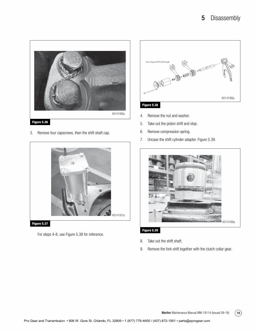
3. Remove four capscrews, then the shift shaft cap.
Figure 5.37
For steps 4-8, use Figure 5.38 for reference.
Figure 5.38
4. Remove the nut and washer.
5. Take out the piston shift and stop.
6. Remove compression spring.
7. Uncase the shift cylinder adapter. Figure 5.39.
Figure 5.39
8. Take out the shift shaft.
9. Remove the fork shift together with the clutch collar gear.
Figure 5.36
Figure 5.37
4014186a
4014187a
Figure 5.38
Figure 5.39
4014188a
4014189a
0
6 Assembly
20 Meritor Maintenance Manual MM-18114 (Issued 09-18)
6 AssemblyAssembly Make sure all parts are clean, dry and lint free. Any traces of storage wax or paper should be removed. Leave bearings and cups in their wrapper, until ready to use. Do not handle parts any more than necessary.
Unless indicated otherwise, part mating surfaces should be given a light coat of lubricant. Lubriplate is acceptable. A substitute may be used using a mixture of chassis grease and 30W engine oil. The mix should be thin enough to apply with a small brush.
Assembly of SubassembliesIn the following assembly procedures, it is assumed that the various shaft assemblies were completely disassembled. Skip any step that refers to a part that is already assembled. Refer to the General Instructions section for assembly precautions.
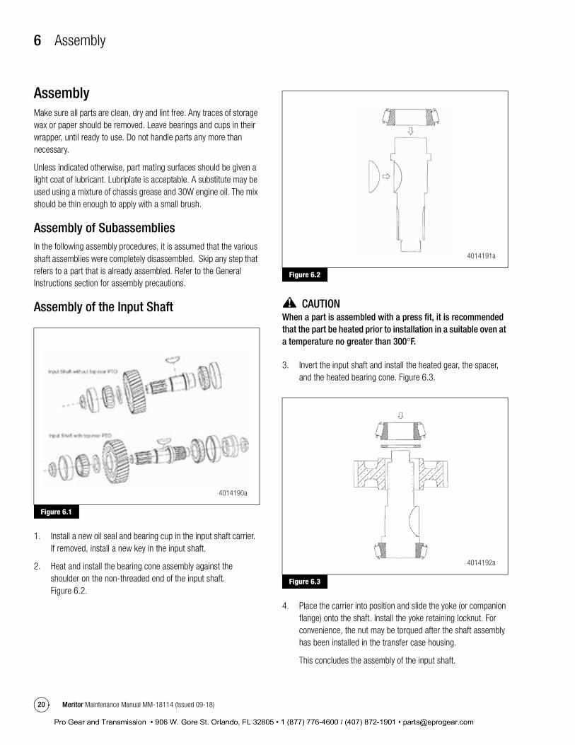
Assembly of the Input Shaft
Figure 6.1
1. Install a new oil seal and bearing cup in the input shaft carrier.If removed, install a new key in the input shaft.
2. Heat and install the bearing cone assembly against theshoulder on the non-threaded end of the input shaft.Figure 6.2.
Figure 6.2
CAUTIONWhen a part is assembled with a press fit, it is recommended that the part be heated prior to installation in a suitable oven at a temperature no greater than 300°F.
3. Invert the input shaft and install the heated gear, the spacer,and the heated bearing cone. Figure 6.3.
Figure 6.3
4. Place the carrier into position and slide the yoke (or companionflange) onto the shaft. Install the yoke retaining locknut. Forconvenience, the nut may be torqued after the shaft assemblyhas been installed in the transfer case housing.
This concludes the assembly of the input shaft.
Figure 6.1
4014190a
Figure 6.2
Figure 6.3
4014191a
4014192a
L _J
A
0

6 Assembly
21Meritor Maintenance Manual MM-18114 (Issued 09-18)
Assembly of the Intermediate Shaft
Figure 6.4
1. If removed, reinstall the keys into the key-ways of theintermediate shaft.
CAUTIONWhen a part is assembled with a press fit, it is recommended that the part be heated prior to installation in a suitable oven at a temperature no greater than 300°F.
2. Heat the bearing cones and intermediate gear and press ontothe intermediate shaft. Figure 6.5.
Figure 6.5
The remainder of the intermediate shaft assembly must be done inside of the transfer case housing during the shaft installation procedure.
This concludes the assembly of the intermediate shaft.
Assembly of the Front Output and PTO Shaft
Figure 6.6
1. Install the snap ring on the shaft.
2. Place the shaft in an upright position, with the fine-threadedend up, to protect the shaft threads and splines.
3. Install the clutch collar gear onto the shaft such that thecounter bore in the gear fits over the snap ring. Ensure clutchcollar gear is mated against snap ring before installing bearingcone.
CAUTIONWhen a part is assembled with a press fit, it is recommended that the part be heated prior to installation in a suitable oven at a temperature no greater than 300°F. Heated components must be allowed to cool before end float measurements are made.
4. Heat the inner bearing cone and install it against clutch gear.
5. Install the inner bearing spacer ring. The bearing cone spacer ring is a select-fit part that is used to adjust the shaft end float. If the end float checked prior to disassembly was within specification (0.002 to 0.004 in.) and no parts were replaced, the original bearing spacer ring should provide the correct end float on reassembly. Figure 6.7.
Figure 6.4
Figure 6.5
4014193a
4014194a
Figure 6.6
4014195a
A
A
0

6 Assembly
22 Meritor Maintenance Manual MM-18114 (Issued 09-18)
Figure 6.7
6. Press the bearing cups into the carrier.
7. Put the carrier onto the shaft and then the heated outer bearingcone. Figure 6.8.
Figure 6.8
8. Do not install oil seal at this time. Slide the yoke (or companionflange) onto the shaft. Install and torque the locknut.
9. Mount a dial indicator on the shaft as shown in Figure 6.9.
Figure 6.9
10. Lift the carrier up and note the indicated shaft end float on the dial indicator. If the end float is not within specification (0.002 to 0.004 in), it will be necessary to disassemble the shaft and repeat steps 5-8 using a bearing spacer ring of a different thickness.
11. Remove the yoke (or companion flange) and install the oil seal.
This concludes the assembly of the front output and PTO shaft.
CAUTIONWhen a part is assembled with a press fit, it is recommended that the part be heated, prior to installation, in a suitable oven at a temperature no greater than 300°F. Heated components must be allowed to cool before end float measurements are made.
Figure 6.7
Figure 6.8
4014196a
4014197a
Figure 6.9
4014198a
A
0

6 Assembly
23Meritor Maintenance Manual MM-18114 (Issued 09-18)
Assembly of the Rear Output with Neutral and Carrier
Figure 6.10
1. Install the clutch collar gear onto the shaft.
Figure 6.11
CAUTIONWhen a part is assembled with a press fit, it is recommended that the part be heated, prior to installation, in a suitable oven at a temperature no greater than 300°F. Heated components must be allowed to cool before end float measurements are made.
2. Lubricate the thickest part of the shaft and the inner surface ofthe gear. Figure 6.12 and Figure 6.13
Figure 6.12
Figure 6.13
3. Then align and install the gear on the shaft. Figure 6.14.
Figure 6.10
Figure 6.11
4014199a
4014200a
Figure 6.12
Figure 6.13
4014201a
4014202a
A
0

6
Asse
mbl
y
24M
erito
r Mai
nten
ance
Man
ual M
M-1
8114
(Iss
ued
09-1
8)
Figu
re 6
.14
4.In
stal
l a th
rust
was
her a
gain
st th
e ge
ar a
ssem
bly
follo
wed
by
the
smal
l spa
cer.
5.He
at a
nd in
stal
l the
bea
ring
cone
ass
embl
y on
the
shaf
t aga
inst
the
spac
er. T
hen
plac
e th
e cl
utch
gea
r on
top
of th
e be
arin
gas
sem
bly.
Fig
ure
6.15
.
Figu
re 6
.15
6.Ap
ply
Loct
ite 2
90 o
r equ
al to
the
lock
nut a
nd ti
ghte
n to
the
requ
ired
torq
ue.
7.In
vert
shaf
t ass
embl
y an
d in
stal
l the
oth
er b
earin
g co
ne o
n to
pof
the
clut
ch c
olla
r. Pl
ace
the
larg
e sp
acer
abo
ve th
e be
arin
g.Fi
gure
6.16
.
Figu
re 6
.16
8.St
art c
reat
ing
the
shift
-for
k as
sem
bly
by s
lidin
g sh
ift-f
ork
onto
the
shor
ter s
ide
of th
e sh
ifter
-sha
ft. P
lace
a fl
at w
ashe
r on
top
of th
e fo
rk a
nd s
crew
in a
lock
nut u
sing
Loc
tite
272
or e
qual
.Fi
gure
6.17
.
Figu
re 6
.17
9.Pl
ace
an O
-rin
g on
the
3/8
thre
aded
sid
e of
the
shift
er-s
haft
and
atta
ch th
e sh
ift-f
ork
asse
mbl
y on
to th
e cl
utch
col
lar.
Figu
re6.
18.
Figu
re6.
14
Figu
re6.
15
4014
203a
4014
204a
Figu
re6.
16
Figu
re6.
17
4014
205a
4014
206a
0

6 Assembly
25Meritor Maintenance Manual MM-18114 (Issued 09-18)
Figure 6.18
10. Press the bearing cup into the carrier. Figure 6.19.
Figure 6.19
11. Place an O-ring into the insert on the carrier. Figure 6.20.
Figure 6.20
12. Use Loctite 620 or equal on the outer diameter of the oil sealand press it into the carrier. Figure 6.21.
Figure 6.21
13. Align the carrier and place it on top of the bearing cone. Grease up the area between the shift-shaft and the carrier.
14. Place a nylon washer on to the shift-fork assembly. Soak thefelt strip in gear oil and install it in the inner groove of thepiston. Slip an O-ring around the outer groove before sliding itonto the nylon washer. The end of the piston with thecounterbore should be facing outward. Place a washer on topof the piston and screw in a locknut using loctite 272 or equal.Place another nylon washer above the piston. Put an O-ringonto the shift cylinder cap. Figure 6.22.
Figure 6.18
Figure 6.19
4014207a
4014208a
Figure 6.20
Figure 6.21
4014209a
4014210a
0

6 Assembly
26 Meritor Maintenance Manual MM-18114 (Issued 09-18)
Figure 6.22
15. Screw in the shift cylinder cap using four cap screws againusing Loctite 272 or equal. Figure 6.23.
Figure 6.23
16. Slip the yoke (or companion flange) onto the shaft and secure itwith a locknut.
17. Insert the indicator switch actuation pin into place. Therounded end of the pin must face inward. Figure 6.24.
Figure 6.24
18. Install the switch using a new copper washer. Torque tospecification. Figure 6.25.
Figure 6.25
19. Screw in a fitting onto the shift cylinder cap. Figure 6.26.
Figure 6.22
Figure 6.23
4014211a
4014212a
Figure 6.24
Figure 6.25
4014213a
4014214a
0

6 Assembly
27Meritor Maintenance Manual MM-18114 (Issued 09-18)
Figure 6.26
This concludes the assembly of the rear output shaft with neutral.
General Assembly — Intermediate Shaft Installation
Figure 6.27
1. Position the transfer case with its front end (nameplate) facingupward.
2. Heat the intermediate shaft gear and lower it into the transfercase housing through the lower or upper shaft bore. Positionthe gear against the rear of the housing in line with theintermediate shaft bores. Figure 6.28.
Figure 6.28
3. Quickly lower the intermediate shaft assembly through thegear. Be sure that the gear is firmly seated against the shaftshoulder.
4. Place one of the bearing cups into its bore in the front of thehousing. Install the front intermediate shaft cap with a newgasket. Figure 6.29.
Figure 6.29
5. Install the six cap screws and washers. Torque to specification.Figure 6.30.
Figure 6.26
Figure 6.27
4014215a
4014216a
Figure 6.28
Figure 6.29
4014217a
4014217a
0

6 Assembly
28 Meritor Maintenance Manual MM-18114 (Issued 09-18)
Figure 6.30
6. Rotate the TC over so that its rear end is facing upward. Toprevent damage, reach in the case and support theintermediate shaft assembly as the unit is rotated.
7. Slip the spacer washer over the intermediate shaft against thegear. Heat and install the remaining bearing cone assemblyagainst the spacer washer. Figure 6.31.
Figure 6.31
8. Place the bearing cup into its bore. Install the rear cap with theoriginal shim pack. Figure 6.32.
Figure 6.32
9. Install the six cap screws and washers. Torque to specification.
10. Rotate transfer case over such that its shafts are horizontal.Mount a dial indicator such that the indicator tip rests againstthe end of the shaft. Figure 6.33.
Figure 6.33
11. Pry the gear up and down several times to be sure that thebearing cups are seated. Note the indicated shaft end float on the dial indicator. If the end float is not within specification(0.002 to 0.004 in), the shim pack should be removed and replaced with a combination of shims which will provide the proper end float. Be sure to recheck the end float after replacing with new shims.
Figure 6.30
Figure 6.31
4014219a
4014220a
Figure 6.32
Figure 6.33
4014221a
4014222a
0

6 Assembly
29Meritor Maintenance Manual MM-18114 (Issued 09-18)
12. Install the oil pump using a gasket and four bolts. Torque tospecifications. Figure 6.34.
Figure 6.34
Rear Output Shaft Installation
Figure 6.35
1. Position the transfer case with its front end (nameplate) facingupward.
2. If removed, install the freeze plug into the shifter shaft bore ofthe front declutch housing. Use non-hardening sealer toprevent an oil leak.
3. Insert the front bearing cup into its bore and place the originalshim pack on top of the bearing cup. Ensure that the declutchin the next step compresses the bearing cup and shims intoplace. Figure 6.36.
Figure 6.36
4. Position the front declutch housing on the transfer case suchthat the shifter shaft bores are directly to the left of the lowershaft bore (as viewed when the unit is installed in the vehicle).Figure 6.37.
Figure 6.37
5. Install the six 12-point cap screws and torque to specification.
6. Rotate the TC over so that its rear end is facing upward.
7. Position a new gasket on the TC housing and lower the rearoutput shaft assembly into place. Figure 6.38.
Figure 6.34
Figure 6.35
4014223a
4014224a
Figure 6.36
Figure 6.37
4014225a
4014226a
0

6 Assembly
30 Meritor Maintenance Manual MM-18114 (Issued 09-18)
Figure 6.38
8. The word “TOP” on the rear carrier must be toward the top of the transfer case as installed in the vehicle as in Figure 6.37. Install the ten cap screws and washers to secure the carrier to the TC housing. Torque to specification.
9. Rotate transfer case over such that its shafts are horizontal. Mount a dial indicator on the shaft as shown in Figure 6.39. Pry the rear output shaft up and down several times to be sure that the front bearing cup is seated. Note the indicated shaft end float on the dial indicator. If the end float is not within specification (0.002 to 0.004 in.), the shim pack should be removed and replaced with a combination of shims which will provide the specified end float. Be sure to recheck the end float after replacing with new shims.
Figure 6.39
Front Output and PTO Shaft Installation
Figure 6.40
1. In order to install the Front output shaft it is necessary toreinstall the shift shaft assembly.
2. Position the transfer case with its front end (name plate)upward. The front declutch housing should already beinstalled.
3. Slide the shift fork onto the clutch collar and place the twoparts, as a unit, into the declutch housing. Figure 6.41.
Figure 6.41
4. The clutch collar and fork must be installed in the rightdirection, so that the shift fork bolts can be installed on themachined side. Figure 6.42.
Figure 6.38
Figure 6.39
4014227a
4014228a
Figure 6.40
Figure 6.41
4014229a
4014230a
0

6 Assembly
31Meritor Maintenance Manual MM-18114 (Issued 09-18)
Figure 6.42
5. Insert the shift shaft into position. Rotate the shift shaft so thatthe slots lineup with the bolt holes in the shift fork. Install the(2) shift fork bolts and torque to specification. Install the lockwire between the two bolt heads. Figure 6.43.
Figure 6.43
6. Install a new piston-to-shaft O-ring over the threaded portion of the shaft. Slide the spring over the shaft. Place the nylon stopring over the shaft and spring. Install a new piston O-ring in the outer groove in the piston. Soak the air shift piston felt strip ingear oil and install it in the inner groove. Figure 6.44.
Figure 6.44
7. Position the piston on the shifter shaft. The end of the pistonwith the counterbore should be facing outward. Push the pistondown to compress the spring and install the shifter shaftwasher and locknut. Torque the nut to specification.Figure 6.45.
Figure 6.45
8. Install the declutch housing cover with a new gasket. Torquethe four cap screws to specification. Figure 6.46.
Figure 6.42
Figure 6.43
4014231a
4014232a
Figure 6.44
Figure 6.45
4014234a
4014235a
0
6 Assembly
32 Meritor Maintenance Manual MM-18114 (Issued 09-18)
Figure 6.46
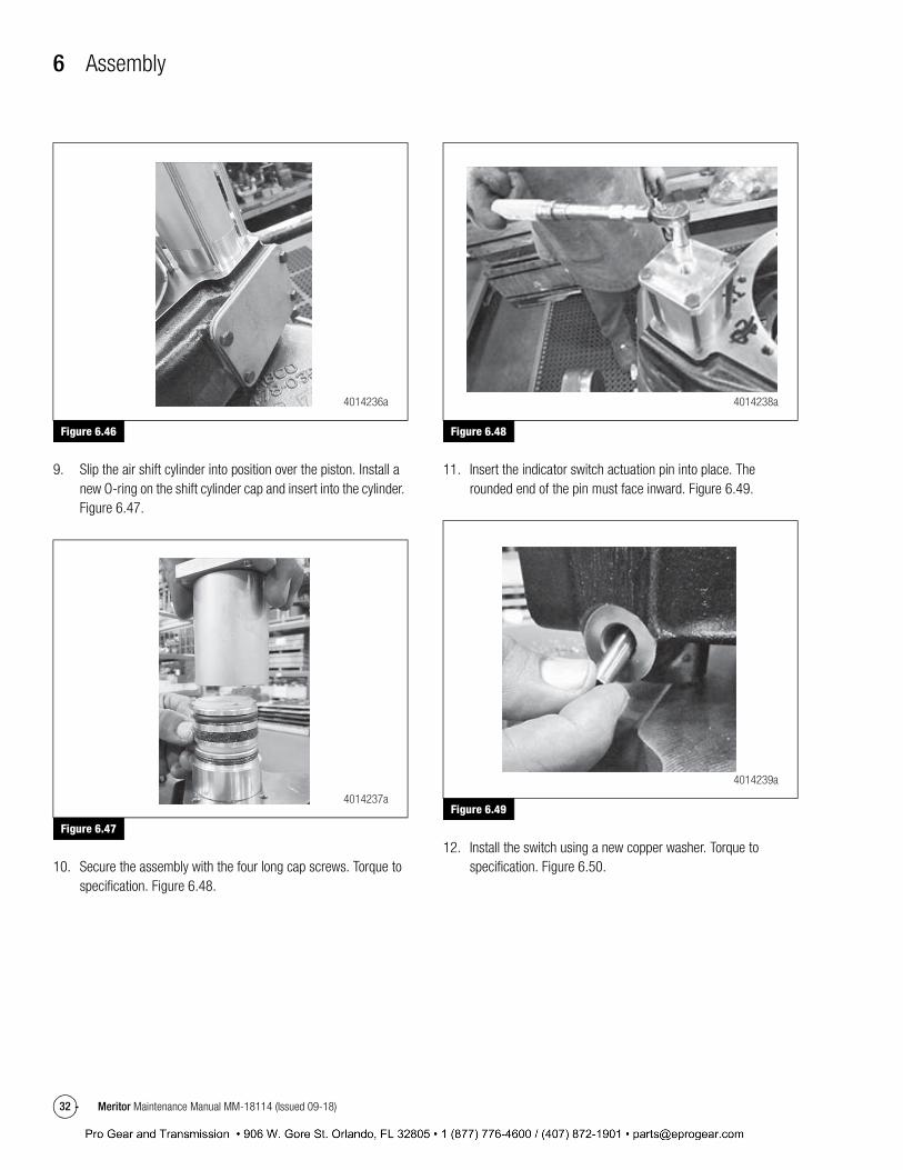
9. Slip the air shift cylinder into position over the piston. Install anew O-ring on the shift cylinder cap and insert into the cylinder.Figure 6.47.
Figure 6.47
10. Secure the assembly with the four long cap screws. Torque tospecification. Figure 6.48.
Figure 6.48
11. Insert the indicator switch actuation pin into place. Therounded end of the pin must face inward. Figure 6.49.
Figure 6.49
12. Install the switch using a new copper washer. Torque tospecification. Figure 6.50.
Figure 6.46
Figure 6.47
4014236a
4014237a
Figure 6.48
Figure 6.49
4014238a
4014239a
0

6 Assembly
33Meritor Maintenance Manual MM-18114 (Issued 09-18)
Figure 6.50
13. Using a new gasket and eight cap screws, install the frontoutput shaft assembly to the declutch housing. Torque tospecification. Figure 6.51.
Figure 6.51
Input Shaft Installation
Figure 6.52
1. Position the transfer case with its rear end facing upward.
2. Insert the rear bearing cup into the bore on the housing. Usethe original shim pack. Figure 6.53.
Figure 6.53
3. Align and install the PTO declutch housing or cap on to thetransfer case housing. Figure 6.54.
Figure 6.50
Figure 6.51
4014240a
4014241a
Figure 6.52
Figure 6.53
4014242a
4014243a
0

6 Assembly
34 Meritor Maintenance Manual MM-18114 (Issued 09-18)
Figure 6.54
4. Install the six 12-point cap screws and torque to specification.
5. Rotate the transfer case over so that its front end is facingupward.
6. Make sure that the rear bearing cup is still in place. Position anew gasket on the transfer case housing and lower the shaftassembly into place. Figure 6.55.
Figure 6.55
7. Align and install the carrier. The word “TOP” on the carriermust be toward the top of the transfer case as installed in thevehicle. Torque the ten cap screws and washers tospecification. Figure 6.56.
Figure 6.56
8. Rotate transfer case such that the shafts are horizontal. Mounta dial indicator on the shaft as shown in Figure 6.57.
Figure 6.57
9. Pry the gear up and down several times to be sure that the bearing cups are seated. Note the indicated shaft end float on the dial indicator. If the end float is not within specification(0.002 to 0.004 in), the shim pack should be removed and replaced with a combination of shims which will provide the proper end float. Be sure to recheck the end float after replacing with new shims.
10. To install the PTO Shaft turn the TC housing so its rear is facing up and follow steps in Front Output and PTO Shaft Installation, starting with step 3.
Figure 6.54
Figure 6.55
4014244a
4014245a
Figure 6.56
Figure 6.57
4014246a
4014247a
0

7 Torque Specifications
35Meritor Maintenance Manual MM-18114 (Issued 09-18)
7 Torque SpecificationsTorque Specifications
Figure 7.1
Figure 7.1
4014248a
800 FT- LBS
45 fT LBS~ 50 FT-L BS
45 FT -L BS
800 FT- LBS-
45 FT-L BS ~ 45 fl- LBS
45 FT-LBS~
45 FT·L BS 45 FT -LBS-
ALL TORQUE (LB-FT) VALUES ARE FOR DRY UNLUBRICATED THREADS AND SHOULD BE WITHIN I0X OF THE VALUES SHOWN .
0

7 Torque Specifications
36 Meritor Maintenance Manual MM-18114 (Issued 09-18)
Figure 7.2
Figure 7.2
4014249a
45 FT ·LBS
800 FT·LBS
0
800 rr · LBS SO FT-LBS- 45 f I ·LBS
45 FT ·LBS I 45 FT·LBS
500 FT·LBS
800 FT ·LBS
45 FT ·LBS ~5 FT-LBS-
800 FT ·LBS
45 rT · LBS
ALL TORQUE (LB-FTl VALUES ARE FOR DRY UN LUBR ICA TE D TH READS AND SHOULD BE WITHIN 10% OF THE VALUES SHOWN .

7 Torque Specifications
37Meritor Maintenance Manual MM-18114 (Issued 09-18)
Figure 7.3
Figure 7.3
4014250a
25 FT-LBS
45 FT-LBS
ADDITIONAL TORQUE SPECIFICATIONS
OIL FILL PLUG ..................................... 50 FT-LBS
OIL LEVEL SIGHT PLUG .................... 50 FT-LBS
TEMPERATURE SENSOR PLUG ........ 25 FT-LBS
OIL FILTER BRACKET.. ...................... 15 FT-LBS
ALL TORQUE (FT-LBS) VALUES ARE FOR DRY UNLUBRICATED THREADS, AND SHOULD BE WITH IN 10% OF THE VALUES SHOWN.
8 FT-LBS
0

8 Seal Installation Instructions
38 Meritor Maintenance Manual MM-18114 (Issued 09-18)
8 Seal Installation InstructionsSeal Installation Instructions1. Drop driveline to access the yoke or flange retaining nut.
2. Remove the retaining nut from the shaft. Input sectional viewshown in Figure 8.1.
Figure 8.1
3. Pull the yoke straight off the shaft. Inspect yoke to verify it is ingood condition. If excessive wear is noted, the yoke should bereplaced. If any burrs are found on the seal journal or beveledcorner they should be removed if the yoke is to be reinstalled.
CAUTIONCare must be exercised to avoid drive yoke damage.
4. Pull the old seal from the housing carrier. For the input location,remove three screws and washers prior to seal removal.
5. Clean the seal bore in the housing carrier where the old sealhad been located.
6. Inspect the new seal to verify that the lip material is intact andin good condition free of any nicks or marks. Also check theoutside diameter of the new seal for any dents or burrs. If anyare found the seal should not be installed.
7. Place seal on seal driver tool as shown in Figure 104 below,ensuring the spring side is facing away fromseal driver tool. Fortop input and rear output locations, use seal (732-0467), andseal driver (866-0888). For Front output location, use seal(732-0466), and seal driver (866-0861). Figure 8.2.
Figure 8.2
8. Place seal driver on shaft. For input location, drive seal intobore with old nut (688-0738). For Front and Rear outputlocations, drive seal into bore with old retaining nut. Seal driverwill stop when seal is fully seated against shoulder on housingcarrier bore. Input installation shown in Figure 8.3.
Figure 8.3
9. For input location, remove old nut and seal driver. Re-installscrews and washers. For Front and Rear output locations,remove old nut and seal driver.
10. Lubricate the shaft splines, seal lips, drive yoke seal journal,and drive yoke bevel with transfer case fluid.
Figure 8.1
4014251a
Figure 8.2
Figure 8.3
4014252a
4014253a
A
0

8 Seal Installation Instructions
39Meritor Maintenance Manual MM-18114 (Issued 09-18)
11. Start the drive yoke on the shaft, ensuring the splines areproperly engaged and slide freely. Push the drive yoke onto theshaft until it seats.
12. Check dust lip to ensuring that it is not folded under and isfacing out. If dust lip is folded under pull out drive yoke 1/2 to 1inch, rotate and push-in reseating drive yoke. Repeat until dustlip is correctly installed.
13. For input location, install a new unused retaining locknut.Torque the nut to 800 lb-ft. For Front and Rear outputlocations, install a new unused retaining locknut. Torque thenut to 800 lb-ft.
14. Rotate the drive yoke by hand to check for binding orinterference.
15. Recheck oil level and fill as necessary.
0

9 Tools
40 Meritor Maintenance Manual MM-18114 (Issued 09-18)
9 ToolsTool DrawingsDetails of tooling to facilitate the servicing of the transfer case. Service tools may be manufactured to these drawings.
The manufacture of these tools should be carried out by professional machinists and certified welders, following typical and good workmanship procedures and safe practices.
Figure 9.1
Figure 9.1
4014254a
[lJ
0
... .. ..
-- OILSEAL 732-04$7 '

9 Tools
41Meritor Maintenance Manual MM-18114 (Issued 09-18)
Figure 9.2
Figure 9.2
4014255a
]>
;~
~~~
~ - - - - -
!" ~ ~ ru
,, 0
J> td
7 "" ig
_l
n t:J
f,o------~-------1
n
--=1.11ai OIL SEAL 732-0466
t::J
w
I\)
0

9 Tools
42M
eritor Maintenance M
anual MM
-18114 (Issued 09-18)
Figure 9.3
Figure9.3
4014256a
0
I----0 4.50 --
_, - 0 3.50
0 3.00
866-0751 SETUP SLEEVE, REAR OUTPUT SHAFT
1.75 --+--- -l
.50-j
R.06
.03 x 45 · CHAMFER 3 PLCS. OUTSIDE 2 P LCS. INSIDE

Meritor Heavy Vehicle Systems, LLC2135 West Maple Road Printed in USATroy, MI 48084 USA866-OnTrac1 (668-7221) Copyright 2018 Issued 09-18meritor.com Meritor, Inc. Maintenance Manual MM-18114 (16579) ~MERITOR