maintenance manual mm-0440 heavy-duty “p” series cam brakes · meritor heavy vehicle systems,...
TRANSCRIPT

Maintenance Manual MM-0440
Heavy-Duty “P” Series Cam BrakesIssued 09-04

Service Notes
Information contained in this publication was in effect at the time the publication was approved for printing and is subject to change without notice or liability. Meritor Heavy Vehicle Systems, LLC, reserves the right to revise the information presented or to discontinue the production of parts described at any time.
Meritor Maintenance Manual MM-0440 (Issued 09-04)
About This ManualThis manual provides maintenance and service information for Meritor heavy-duty “P” Series cam brakes.
Before You Begin1. Read and understand all instructions and procedures before
you begin to service components.
2. Read and observe all Warning and Caution hazard alert messages in this publication. They provide information that can help prevent serious personal injury, damage to components, or both.
3. Follow your company’s maintenance and service, installation, and diagnostics guidelines.
4. Use special tools when required to help avoid serious personal injury and damage to components.
Hazard Alert Messages and Torque Symbols
WARNINGA Warning alerts you to an instruction or procedure that you must follow exactly to avoid serious personal injury and damage to components.
CAUTIONA Caution alerts you to an instruction or procedure that you must follow exactly to avoid damage to components.
@ This symbol alerts you to tighten fasteners to a specified torque value.
How to Obtain Product and Service Information
On the Web
Visit the DriveTrain Plus™ by ArvinMeritor Tech Library at arvinmeritor.com to easily access product and service information. The Library also offers an interactive and printable Literature Order Form.
ArvinMeritor’s Customer Service Center
Call ArvinMeritor’s Customer Service Center at 800-535-5560.
Technical Electronic Library on CD
The DriveTrain Plus™ by ArvinMeritor Technical Electronic Library on CD contains product and service information for most Meritor and Meritor WABCO products. $20. Specify TP-9853.
How to Obtain Tools and SuppliesCall ArvinMeritor’s Commercial Vehicle Aftermarket at 888-725-9355 to obtain Meritor tools and supplies.
Contents
pg. i Asbestos and Non-Asbestos Fibers 1 Section 1: Exploded View 2 Section 2: Introduction
DescriptionCam Brake Tips
4 Section 3: Removal and DisassemblyRemovalWheel Components
5 Brake ShoesCamshaft and Slack Adjuster
6 Section 4: Prepare Parts for AssemblyClean, Dry and Inspect PartsClean and Dry PartsCorrosion ProtectionInspect Parts
9 Section 5: Assembly and InstallationInstallationCamshaft Assemblies
10 Brake ShoesSlack Adjusters
12 Section 6: AdjustmentAdjust the BrakesMeasure Free Stroke
13 Commercial Vehicle Safety Alliance (CVSA) Guidelines
15 Section 7: Reline the BrakesReline the BrakesInstalling Linings with Rivets
16 Installing Linings with BoltsOversize Drums
17 Section 8: MaintenanceLubricationBrake Assembly Components
18 Slack Adjuster19 Intervals
ApplicationsAdjust the BrakesReline the BrakesImportant Information on Linings and Primary Shoe
Locations20 Major Overhaul
InspectionBefore You Return the Vehicle to Service
22 Section 9: SpecificationsTorque Specifications
Asbestos and Non-Asbestos Fibers
iMeritor Maintenance Manual MM-0440 (Issued 09-04)
Figure 0.1
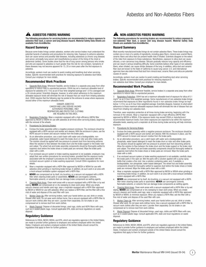
ASBESTOS FIBERS WARNING The following procedures for servicing brakes are recommended to reduce exposure toasbestos fiber dust, a cancer and lung disease hazard. Material Safety Data Sheets areavailable from ArvinMeritor.
Hazard SummaryBecause some brake linings contain asbestos, workers who service brakes must understand the potential hazards of asbestos and precautions for reducing risks. Exposure to airborne asbestos dust can cause serious and possibly fatal diseases, including asbestosis (a chronic lung disease) and cancer, principally lung cancer and mesothelioma (a cancer of the lining of the chest or abdominal cavities). Some studies show that the risk of lung cancer among persons who smoke and who are exposed to asbestos is much greater than the risk for non-smokers. Symptoms of these diseases may not become apparent for 15, 20 or more years after the first exposure to asbestos.
Accordingly, workers must use caution to avoid creating and breathing dust when servicing brakes. Specific recommended work practices for reducing exposure to asbestos dust follow. Consult your employer for more details.
Recommended Work Practices1. Separate Work Areas. Whenever feasible, service brakes in a separate area away from other operations to reduce risks to unprotected persons. OSHA has set a maximum allowable level of exposure for asbestos of 0.1 f/cc as an 8-hour time-weighted average and 1.0 f/cc averaged over a 30-minute period. Scientists disagree, however, to what extent adherence to the maximum allowable exposure levels will eliminate the risk of disease that can result from inhaling asbestos dust. OSHA requires that the following sign be posted at the entrance to areas where exposures exceed either of the maximum allowable levels:
DANGER: ASBESTOSCANCER AND LUNG DISEASE HAZARD
AUTHORIZED PERSONNEL ONLYRESPIRATORS AND PROTECTIVE CLOTHING
ARE REQUIRED IN THIS AREA.
2. Respiratory Protection. Wear a respirator equipped with a high-efficiency (HEPA) filter approved by NIOSH or MSHA for use with asbestos at all times when servicing brakes, beginning with the removal of the wheels.
3. Procedures for Servicing Brakes.
a. Enclose the brake assembly within a negative pressure enclosure. The enclosure should be equipped with a HEPA vacuum and worker arm sleeves. With the enclosure in place, use the HEPA vacuum to loosen and vacuum residue from the brake parts.
b. As an alternative procedure, use a catch basin with water and a biodegradable, non-phosphate, water-based detergent to wash the brake drum or rotor and other brake parts. The solution should be applied with low pressure to prevent dust from becoming airborne. Allow the solution to flow between the brake drum and the brake support or the brake rotor and caliper. The wheel hub and brake assembly components should be thoroughly wetted to suppress dust before the brake shoes or brake pads are removed. Wipe the brake parts clean with a cloth.
c. If an enclosed vacuum system or brake washing equipment is not available, employers may adopt their own written procedures for servicing brakes, provided that the exposure levels associated with the employer’s procedures do not exceed the levels associated with the enclosed vacuum system or brake washing equipment. Consult OSHA regulations for more details.
d. Wear a respirator equipped with a HEPA filter approved by NIOSH or MSHA for use with asbestos when grinding or machining brake linings. In addition, do such work in an area with a local exhaust ventilation system equipped with a HEPA filter.
e. NEVER use compressed air by itself, dry brushing, or a vacuum not equipped with a HEPA filter when cleaning brake parts or assemblies. NEVER use carcinogenic solvents, flammable solvents, or solvents that can damage brake components as wetting agents.
4. Cleaning Work Areas. Clean work areas with a vacuum equipped with a HEPA filter or by wet wiping. NEVER use compressed air or dry sweeping to clean work areas. When you empty vacuum cleaners and handle used rags, wear a respirator equipped with a HEPA filter approved by NIOSH or MSHA for use with asbestos. When you replace a HEPA filter, wet the filter with a fine mist of water and dispose of the used filter with care.
5. Worker Clean-Up. After servicing brakes, wash your hands before you eat, drink or smoke. Shower after work. Do not wear work clothes home. Use a vacuum equipped with a HEPA filter to vacuum work clothes after they are worn. Launder them separately. Do not shake or use compressed air to remove dust from work clothes.
6. Waste Disposal. Dispose of discarded linings, used rags, cloths and HEPA filters with care, such as in sealed plastic bags. Consult applicable EPA, state and local regulations on waste disposal.
Regulatory GuidanceReferences to OSHA, NIOSH, MSHA, and EPA, which are regulatory agencies in the United States, are made to provide further guidance to employers and workers employed within the United States. Employers and workers employed outside of the United States should consult the regulations that apply to them for further guidance.
NON-ASBESTOS FIBERS WARNING The following procedures for servicing brakes are recommended to reduce exposure tonon-asbestos fiber dust, a cancer and lung disease hazard. Material Safety DataSheets are available from ArvinMeritor.
Hazard SummaryMost recently manufactured brake linings do not contain asbestos fibers. These brake linings may contain one or more of a variety of ingredients, including glass fibers, mineral wool, aramid fibers, ceramic fibers and silica that can present health risks if inhaled. Scientists disagree on the extent of the risks from exposure to these substances. Nonetheless, exposure to silica dust can cause silicosis, a non-cancerous lung disease. Silicosis gradually reduces lung capacity and efficiency and can result in serious breathing difficulty. Some scientists believe other types of non-asbestos fibers, when inhaled, can cause similar diseases of the lung. In addition, silica dust and ceramic fiber dust are known to the State of California to cause lung cancer. U.S. and international agencies have also determined that dust from mineral wool, ceramic fibers and silica are potential causes of cancer.
Accordingly, workers must use caution to avoid creating and breathing dust when servicing brakes. Specific recommended work practices for reducing exposure to non-asbestos dust follow. Consult your employer for more details.
Recommended Work Practices1. Separate Work Areas. Whenever feasible, service brakes in a separate area away from other operations to reduce risks to unprotected persons.
2. Respiratory Protection. OSHA has set a maximum allowable level of exposure for silica of 0.1 mg/m3 as an 8-hour time-weighted average. Some manufacturers of non-asbestos brake linings recommend that exposures to other ingredients found in non-asbestos brake linings be kept below 1.0 f/cc as an 8-hour time-weighted average. Scientists disagree, however, to what extent adherence to these maximum allowable exposure levels will eliminate the risk of disease that can result from inhaling non-asbestos dust.
Therefore, wear respiratory protection at all times during brake servicing, beginning with the removal of the wheels. Wear a respirator equipped with a high-efficiency (HEPA) filter approved by NIOSH or MSHA, if the exposure levels may exceed OSHA or manufacturers’ recommended maximum levels. Even when exposures are expected to be within the maximum allowable levels, wearing such a respirator at all times during brake servicing will help minimize exposure.
3. Procedures for Servicing Brakes.
a. Enclose the brake assembly within a negative pressure enclosure. The enclosure should be equipped with a HEPA vacuum and worker arm sleeves. With the enclosure in place, use the HEPA vacuum to loosen and vacuum residue from the brake parts.
b. As an alternative procedure, use a catch basin with water and a biodegradable, non-phosphate, water-based detergent to wash the brake drum or rotor and other brake parts. The solution should be applied with low pressure to prevent dust from becoming airborne. Allow the solution to flow between the brake drum and the brake support or the brake rotor and caliper. The wheel hub and brake assembly components should be thoroughly wetted to suppress dust before the brake shoes or brake pads are removed. Wipe the brake parts clean with a cloth.
c. If an enclosed vacuum system or brake washing equipment is not available, carefully clean the brake parts in the open air. Wet the parts with a solution applied with a pump-spray bottle that creates a fine mist. Use a solution containing water, and, if available, a biodegradable, non-phosphate, water-based detergent. The wheel hub and brake assembly components should be thoroughly wetted to suppress dust before the brake shoes or brake pads are removed. Wipe the brake parts clean with a cloth.
d. Wear a respirator equipped with a HEPA filter approved by NIOSH or MSHA when grinding or machining brake linings. In addition, do such work in an area with a local exhaust ventilation system equipped with a HEPA filter.
e. NEVER use compressed air by itself, dry brushing, or a vacuum not equipped with a HEPA filter when cleaning brake parts or assemblies. NEVER use carcinogenic solvents, flammable solvents, or solvents that can damage brake components as wetting agents.
4. Cleaning Work Areas. Clean work areas with a vacuum equipped with a HEPA filter or by wet wiping. NEVER use compressed air or dry sweeping to clean work areas. When you empty vacuum cleaners and handle used rags, wear a respirator equipped with a HEPA filter approved by NIOSH or MSHA, to minimize exposure. When you replace a HEPA filter, wet the filter with a fine mist of water and dispose of the used filter with care.
5. Worker Clean-Up. After servicing brakes, wash your hands before you eat, drink or smoke. Shower after work. Do not wear work clothes home. Use a vacuum equipped with a HEPA filter to vacuum work clothes after they are worn. Launder them separately. Do not shake or use compressed air to remove dust from work clothes.
6. Waste Disposal. Dispose of discarded linings, used rags, cloths and HEPA filters with care, such as in sealed plastic bags. Consult applicable EPA, state and local regulations on waste disposal.
Regulatory GuidanceReferences to OSHA, NIOSH, MSHA, and EPA, which are regulatory agencies in the United States, are made to provide further guidance to employers and workers employed within the United States. Employers and workers employed outside of the United States should consult the regulations that apply to them for further guidance.

1 Exploded View
1Meritor Maintenance Manual MM-0440 (Issued 09-04)
1 Exploded View
Figure 1.1
22
21
20
23
19
18
16
17
13
14
15
12
4004493a
11
10
9
6
7
8
1 2 3 4 5
Item Description
1 Camshaft and Chamber Bracket
2 Bracket Capscrews
3 Bracket Lock Washers
4 Bracket-to-Spider Spacer
5 Manual Slack Adjuster
6 Cam Spacing Washer
7 Cam Head Washer
8 Small Spacing Washer
9 Cam Needle Bearing
10 Shoe and Lining Assembly
11 Anchor Pin Lock Screw
12 Brake Spider
13 Brake Shoe Anchor Pin
14 Anchor Pin Lock
15 Anchor Pin Felt Retainer
16 Anchor Pin Felt
17 Shoe Return Spring
18 Double Head Cam
19 Clevis Pin
20 Cotter Pin
21 Chamber Stud Nut
22 Chamber Stud Washer
23 Air Chamber
Item Description

2 Introduction
2 Meritor Maintenance Manual MM-0440 (Issued 09-04)
2 IntroductionDescriptionMeritor “P” Series cam brakes are air actuated and cam operated with two brake shoes – each mounted on a separate anchor. The brakes are designed for heavy-duty on- or off-highway applications and special equipment where larger shoe and drum areas are necessary. Brake diameters of 20.25-inches and 22-inches are available with automatic or manual adjustment. The brakes can be assembled with auxiliary spring brakes. Figure 2.1.
Figure 2.1
Cam Brake Tips
Air Chambers
To ensure correct brake balance, all brake chambers on the same axle must be the same size and type to help ensure a balanced brake system for maximum lining wear and drum life.
Brake Kits
Meritor brake shoes, rollers, camshafts and shoe return springs are designed to perform as a system. Always install original equipment manufacturer spec-level components during maintenance or when you upgrade from standard to long-life brakes to help ensure correct brake performance and maximum lining life.
Cam Heads
Cam heads can look the same, but that doesn’t mean they will perform the same in your brake system. Two cam head profiles can appear to be identical, but very small differences in cams from different manufacturers can be significant enough to affect the performance of your brakes. To ensure a balanced brake system and optimum lining and drum life, always install the correct replacement cam.
Cam Rollers
To avoid flat spots, lubricate a cam roller directly in the web roller pocket and not at the cam-to-roller contact area. Flat spots can affect brake adjustment and result in premature brake wear or reduced braking performance.
Drums
To help ensure balanced braking, even lining and drum wear, and correct function of the automatic slack adjuster, do not install a cast drum and a composite drum on the same axle.
A cast drum and a composite drum each absorbs and dissipates heat differently. When drum types and weights are mixed, different rates of heat absorption and dissipation occur that can affect the brake system.
Hardware
When you service cam brakes, replace all the springs, anchor pins, bushings and rollers — not just the shoe return springs — to help ensure maximum braking performance.
Linings
Insist on the same brand of quality original equipment manufacturer friction lining material to help ensure fewer relines and compatibility with your present system.
Replacement Parts
Always use original equipment manufacturer quality standard parts. Meritor brakes work as a system, and when you replace original parts with will-fit parts, you can compromise the performance of the entire system.
Return Springs
Replace cam brake return springs at every cam brake reline. The return spring is critical to alignment, accurate return of the brake away from the drum and correct automatic slack adjustment.
Trailer Cam Brakes
Long-life bushings require correct lubrication for maximum performance and bushing life. Although you do not have to replace spider cam bushings on trailer axles as frequently, Meritor recommends that you lubricate the bushings at least four times during the life of your brake lining.
Figure 2.1
4004873b
HEAVY-DUTY “P” SERIES BRAKE

2 Introduction
3Meritor Maintenance Manual MM-0440 (Issued 09-04)
Automatic Slack Adjusters
Automatic doesn’t mean maintenance-free. Correctly installed and lubricated automatic slack adjusters help to ensure maximum brake system performance.
Never mix automatic slack adjusters on the same axle. When you replace automatic slack adjusters, always use replacement parts that were originally designed for the brake system to help ensure even brake wear, balanced braking and maximum brake performance.

3 Removal and Disassembly
4 Meritor Maintenance Manual MM-0440 (Issued 09-04)
3 Removal and DisassemblyHazard Alert MessagesRead and observe all Warning and Caution hazard alert messages in this publication. They provide information that can help prevent serious personal injury, damage to components, or both.
WARNINGTo prevent serious eye injury, always wear safe eye protection when you perform vehicle maintenance or service.
ASBESTOS AND NON-ASBESTOS FIBERS WARNING
Some brake linings contain asbestos fibers, a cancer and lung disease hazard. Some brake linings contain non-asbestos fibers, whose long-term effects to health are unknown. You must use caution when you handle both asbestos and non-asbestos materials.
Removal
Wheel Components
WARNINGPark the vehicle on a level surface. Block the wheels to prevent the vehicle from moving. Support the vehicle with safety stands. Do not work under a vehicle supported only by jacks. Jacks can slip or fall over. Serious personal injury and damage to components can result.
1. Park the vehicle on a level surface. Block the wheels to prevent the vehicle from moving.
2. Use a jack to raise the vehicle so that the wheels to be serviced are off the ground. Support the vehicle with safety stands.
WARNINGBefore you service a spring chamber, carefully follow the manufacturer’s instructions to compress and lock the spring to completely release the brake. Verify that no air pressure remains in the service chamber before you proceed. Sudden release of compressed air can cause serious personal injury and damage to components.
3. If the brake has spring chambers, carefully cage and lock the spring, so that the spring cannot actuate during assembly.
NOTE: For complete maintenance and service information on Meritor automatic slack adjusters, refer to Maintenance Manual 4, Cam Brakes and Automatic Slack Adjuster. To obtain this publication, refer to the Service Notes page on the front inside cover of this manual.
If the slack adjuster is not a Meritor automatic slack adjuster, refer to the manufacturer’s literature for the correct service procedures.
4. Fully release the slack adjusters so the shoes retract and the drums will clear the linings.
CAUTIONYou must disengage a pull pawl or remove a conventional pawl before rotating the manual adjusting nut, or you will damage the pawl teeth. A damaged pawl will not allow the slack adjuster to automatically adjust brake clearance. Replace damaged pawls before putting the vehicle in service.
A. Disengage the pawl.
� If the slack adjuster has a pull pawl: Use a screwdriver or equivalent tool to pry the pull pawl at least 0.03125-inch (0.8 mm) to disengage the teeth. Figure 3.1.
� If the slack adjuster has a conventional pawl: Remove the pawl assembly, pressure relief capscrew, spring and pawl, from the side of the slack adjuster housing. Figure 3.2.
Figure 3.1
Figure 3.1
CONVENTIONALPAWL
PULL PAWL
PRY UP
PAWL
4000331b

3 Removal and Disassembly
5Meritor Maintenance Manual MM-0440 (Issued 09-04)
Figure 3.2
B. Use a wrench to turn the manual adjusting nut CLOCKWISE until the brake shoes are fully retracted, and the lining clears the drum.
C. Install the pawl into the slack adjuster housing.
5. Follow the manufacturer’s instructions to remove the wheel and drum from the axle.
Brake Shoes
1. Remove the brake shoe return springs.
2. Remove the lock rings, retainers and felt seals from the anchor pins.
3. Cut the lock wire and remove the anchor pin lock screws from the brake spider. Figure 3.3.
Figure 3.3
4. Remove the anchor pins and the brake shoe assemblies.
Camshaft and Slack Adjuster
1. Remove the two clevis pins from the clevis on the air chamber push rod.
2. Remove the slack adjuster from the camshaft.
3. Check the up-and-down and side-to-side end play of the camshaft. Figure 3.4. If end play exceeds 0.030-inch(0.762 mm), replace the needle bearings. Use a press with the correct size driver to remove the needle bearing assemblies.
Figure 3.4
4. Remove the washers, retainers and spacers from the camshaft.
5. Pull the camshaft from the spider and bracket.
Figure 3.2
Figure 3.3
4004494a
PAWLASSEMBLY
MANUALADJUSTING
NUT
4004495a
LOCKSCREWS
Figure 3.4
4000342a
4 Prepare Parts for Assembly
6 Meritor Maintenance Manual MM-0440 (Issued 09-04)
4 Prepare Parts for AssemblyHazard Alert MessagesRead and observe all Warning and Caution hazard alert messages in this publication. They provide information that can help prevent serious personal injury, damage to components, or both.
WARNINGTo prevent serious eye injury, always wear safe eye protection when you perform vehicle maintenance or service.
ASBESTOS AND NON-ASBESTOS FIBERS WARNING
Some brake linings contain asbestos fibers, a cancer and lung disease hazard. Some brake linings contain non-asbestos fibers, whose long-term effects to health are unknown. You must use caution when you handle both asbestos and non-asbestos materials.
Clean, Dry and Inspect Parts
Clean and Dry Parts
WARNINGSolvent cleaners can be flammable, poisonous and cause burns. Examples of solvent cleaners are carbon tetrachloride, and emulsion-type and petroleum-base cleaners. Read the manufacturer’s instructions before using a solvent cleaner, then carefully follow the instructions. Also follow the procedures below.
� Wear safe eye protection.
� Wear clothing that protects your skin.
� Work in a well-ventilated area.
� Do not use gasoline, or solvents that contain gasoline. Gasoline can explode.
� You must use hot solution tanks or alkaline solutions correctly. Read the manufacturer’s instructions before using hot solution tanks and alkaline solutions. Then carefully follow the instructions.
CAUTIONDo not use hot solution tanks or water and alkaline solutions to clean ground or polished parts. Damage to parts can result.
Use soap and water to clean non-metal parts. Dry parts immediately after cleaning with soft, clean paper or cloth, or compressed air.
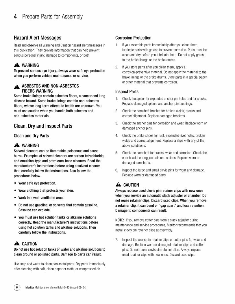
Corrosion Protection
1. If you assemble parts immediately after you clean them, lubricate parts with grease to prevent corrosion. Parts must be clean and dry before you lubricate them. Do not apply grease to the brake linings or the brake drums.
2. If you store parts after you clean them, apply a corrosion-preventive material. Do not apply the material to the brake linings or the brake drums. Store parts in a special paper or other material that prevents corrosion.
Inspect Parts
1. Check the spider for expanded anchor pin holes and for cracks. Replace damaged spiders and anchor pin bushings.
2. Check the camshaft bracket for broken welds, cracks and correct alignment. Replace damaged brackets.
3. Check the anchor pins for corrosion and wear. Replace worn or damaged anchor pins.
4. Check the brake shoes for rust, expanded rivet holes, broken welds and correct alignment. Replace a shoe with any of the above conditions.
5. Check the camshaft for cracks, wear and corrosion. Check the cam head, bearing journals and splines. Replace worn or damaged camshafts.
6. Inspect the large and small clevis pins for wear and damage. Replace worn or damaged parts.
CAUTIONAlways replace used clevis pin retainer clips with new ones when you service an automatic slack adjuster or chamber. Do not reuse retainer clips. Discard used clips. When you remove a retainer clip, it can bend or “gap apart” and lose retention. Damage to components can result.
NOTE: If you remove cotter pins from a slack adjuster during maintenance and service procedures, Meritor recommends that you install clevis pin retainer clips at assembly.
7. Inspect the clevis pin retainer clips or cotter pins for wear and damage. Replace worn or damaged retainer clips and cotter pins. Do not reuse clevis pin retainer clips. Always replace used retainer clips with new ones. Discard used clips.

4 Prepare Parts for Assembly
7Meritor Maintenance Manual MM-0440 (Issued 09-04)
WARNINGDo not operate the vehicle with the brake drum worn or machined beyond the discard dimension indicated on the drum. The brake system may not operate correctly. Damageto components and serious personal injury can result.
CAUTIONReplace the brake drum if it is out-of-round. Do not turn or rebore a brake drum, which decreases the strength and capacity of the drum. Damage to components can result.
8. Use the following procedure to inspect the brake drums.
A. Check the brake drums for cracks, severe heat checking, heat spotting, scoring, pitting and distortion. Replace drums as required. Do not turn or rebore brake drums, which decreases the strength and heat capacity of the drum.
B. Measure the inside diameter of the drum in several locations with a drum caliper or internal micrometer. Figure 4.1.
� If the diameter exceeds the specifications supplied by the drum manufacturer: Replacethe drum.
Figure 4.1
9. Check the dust shields for wear and damage. Repair or replace worn or damaged parts as necessary.
Slack Adjusters
1. If the slack adjuster has a quick connect clevis, check the gap between the clevis and the collar.
� If the gap exceeds 0.060-inch (1.52 mm): Replace the clevis with a one-piece threaded clevis.
2. Check the clevis pins, clips and bushing in the slack adjuster arm for wear and damage. Replace worn or damaged parts. Check the bushing diameter to ensure it does not exceed 0.531-inch (13.5 mm).
� If the bushing diameter exceeds 0.531-inch (13.5 mm): Replace the bushing.
CAUTIONYou must disengage a pull pawl or remove a conventional pawl before rotating the manual adjusting nut, or you will damage the pawl teeth. A damaged pawl will not allow the slack adjuster to automatically adjust brake clearance. Replace damaged pawls before putting the vehicle in service.
NOTE: When you service an automatic slack adjuster with a conventional pawl, replace the conventional pawl with a pull pawl.
3. Disengage the pull pawl. Use a screwdriver or equivalent tool to pry the pull pawl at least 1/32-inch (0.8 mm) to disengage the teeth. Figure 4.2.
� If the slack adjuster has a conventional pawl: Remove the pawl. Figure 4.2.
Figure 4.2
Figure 4.1
4000343a
Figure 4.2
CONVENTIONALPAWL
PULL PAWL
PRY UP
PAWL
4000331b

4 Prepare Parts for Assembly
8 Meritor Maintenance Manual MM-0440 (Issued 09-04)
CAUTIONYou must turn the adjusting nut COUNTERCLOCKWISE when you check gear torque on an automatic slack adjuster. If you turn the adjusting nut incorrectly, you will damage the pawl teeth. A damaged pawl will prevent the slack adjuster from automatically adjusting the clearance between the linings and drum. Damage to components can result.
4. Check manual slack adjusters by rotating the adjustment nut of the worm shaft to verify that the worm drive is free. Figure 4.3. Replace the slack adjuster if the worm drive does not operate correctly. Do NOT repair a manual slack adjuster.
Figure 4.3
5. Use a lb-in torque wrench and turn the adjusting nut COUNTERCLOCKWISE to rotate the gear 360 degrees, or 22 turns of the wrench, as you read the torque scale on the wrench. The value should be less than 25 lb-in (2.83 N�m) as you rotate the gear. Figure 4.4.
� If the torque value is less than 25 lb-in (2.8 N�m) as you rotate the gear: The slack adjuster is operating correctly.
� If the torque value exceeds 25 lb-in (2.8 N�m) as you rotate the gear: Replace the slack adjuster.
Figure 4.4
6. Re-engage the pull pawl. Remove the screwdriver or equivalent tool. The pull pawl will re-engage automatically.
� If the slack adjuster has a conventional pawl: Install the pawl assembly into the housing. Tighten the capscrew to 12-17 lb-ft (16-23 N�m). @
NOTE: If necessary, install a camshaft into the slack adjuster gear to minimize grease flow through the gear holes.
7. Use a grease gun to apply Meritor specification O-616-A, O-692 or O-645 lubricant to the slack adjuster grease fitting, until grease flows from around the camshaft splines and pawl assembly. Refer to Section 8 for more lubricant information.
Figure 4.3
4004496a
ADJUSTMENTNUT
Figure 4.4
22 TURNS
ROTATE GEAR 360°
4000344a

5 Assembly and Installation
9Meritor Maintenance Manual MM-0440 (Issued 09-04)
5 Assembly and InstallationHazard Alert MessagesRead and observe all Warning and Caution hazard alert messages in this publication. They provide information that can help prevent serious personal injury, damage to components, or both.
WARNINGTo prevent serious eye injury, always wear safe eye protection when you perform vehicle maintenance or service.
ASBESTOS AND NON-ASBESTOS FIBERS WARNING
Some brake linings contain asbestos fibers, a cancer and lung disease hazard. Some brake linings contain non-asbestos fibers, whose long-term effects to health are unknown. You must use caution when you handle both asbestos and non-asbestos materials.
Installation
Camshaft Assemblies
1. Tighten all the spider bolts to the specified torque. Figure 5.1.
Figure 5.1
2. Install new camshaft seals into the spider and camshaft bracket with a seal driver. Figure 5.2. Install both seals with their lips toward the slack adjuster. Figure 5.3.
3. If necessary, install new cage and needle bearing assemblies.
Figure 5.2
Figure 5.3
4. If the camshaft bracket was removed, install the gasket and bracket to the spider. Tighten the capscrews to the correct torque as specified in Section 9.
5. Install the cam head thrust washer onto the camshaft. Apply Meritor specification O-617-A or O-617-B grease to the camshaft needle bearings and journals.
6. Install the camshaft through the spider and bracket so that the camshaft turns freely by hand. Figure 5.4.
Figure 5.4
Figure 5.1
4004497a
T
TORQUEBOLTSIZE
7/16"-201/2"-209/16"-185/8"-18
60-75 LB-FT85-115 LB-FT130-165 LB-FT180-230 LB-FT
81-102 N·m115-156 N·m176-224 N·m244-312 N·m
Figure 5.2
Figure 5.3
Figure 5.4
4000346a
SPIDER
CAMSHAFTBRACKET
SEALLIP
SEALLIP
4000347a
4000348a

5 Assembly and Installation
10 Meritor Maintenance Manual MM-0440 (Issued 09-04)
Brake Shoes
NOTE: Meritor recommends that you replace the springs, rollers and anchor pins at each reline.
When the brake is disassembled, or when necessary, lubricate the anchor pins and rollers where these parts touch the brake shoes.
Do not allow grease to contact the area of the camshaft roller that touches the camshaft head.
1. Lubricate the camshaft roller pin and anchor pin with Meritor specification O-617-A or O-617-B grease.
2. Install the brake shoes onto the spider with the anchor pins. Verify that the flat sides of the anchor pins are aligned with the lock screw holes in the spider.
3. Install the anchor pin felt seals, retainers and lock rings.
4. Install the anchor pin lock screws and tighten to 10-15 lb-ft (13.56-20.34 N�m). Install the lock wire for the lock screws. @
5. Install new shoe return springs.
Slack Adjusters
1. Apply Meritor specification O-637 or other rust preventive grease to the camshaft splines.
2. Install the slack adjuster spacer washer on the splined end of the camshaft followed by the slack adjuster.
3. Add spacer washers to limit the slack adjuster end play to 0.060-inch (1.5 mm) maximum. Figure 5.5.
Figure 5.5
4. Install a new camshaft lock ring.
5. Connect the slack adjuster to the air chamber push rod.
Manual Slack Adjusters
1. If the clevis was not replaced, install new clevis pins.
2. Install and adjust the slack adjuster to match the Brake Slack Adjuster Position (BSAP). Figure 5.6.
Figure 5.6
Automatic Slack Adjusters
1. If you install the same slack adjuster that was removed, install the clevis on the push rod in the position you marked when you removed the clevis. Check the position of the clevis with the Installation template. Figure 5.7.
� If you are installing a new slack adjuster: Verify it is the same length as the one you are replacing. Install the clevis on the push rod. Check the position of the clevis with the Installation template. Figure 5.7.
Figure 5.5
4004499a
Check end play.
Figure 5.6
4004498a
3.750 AND 3.812BRACKETOFFSET
BSAP ± 0.062
SLACKLENGTH
CORRECT POSITION OF MANUAL SLACK ADJUSTER 3.750" AND 3.812" OFFSETS ONLY(FOR OTHER BRACKET OFFSETS, REFER TO
THE VEHICLE MANUFACTURER’SSPECIFICATIONS)
5.005.506.006.50
5.005.506.006.50
2.842.752.672.59
SLACKADJUSTMENT
SIZE
± 0.062BSAP

5 Assembly and Installation
11Meritor Maintenance Manual MM-0440 (Issued 09-04)
Figure 5.7
2. Remove the pawl assembly and align the slack adjuster arm with the clevis. Turn the manual adjusting nut to the left until the clevis pin hole in the slack adjuster arm is aligned with the large hole in the clevis. Assemble with the large clevis pin and fasten with a cotter pin. Figure 5.8 and Figure 5.9.
Figure 5.8
Figure 5.9
3. Pull on the actuator rod until the hole in the top of the rod is aligned with the small hole in the clevis. Install the small clevis pin and fasten with a cotter pin.
4. Install the pawl assembly.
5. Apply the brakes and permit the push rods to extend fully. There must be clearance between the slack adjuster and all chassis components.
NOTE: Refer to Maintenance Manual 4, Cam Brakes and Automatic Slack Adjuster, for complete installation instructions.
6. Release the brakes and verify that the manual adjusting nut rotates to the left as the push rods fully retract.
Figure 5.7
Figure 5.8
Color of Template
Part Number Applications
Dark brown TP-4786 Truck or tractor drum brakeTan TP-4787 Trailer drum brakeWhite TP-4781 Coach drum brake
Measure the slack adjuster arm length.
CAMSHAFT CENTER 4000369b
4004500a
PAWLASSEMBLY
MANUALADJUSTING
NUT
Figure 5.9
CLEVISLARGE CLEVIS PIN
ANDRETAINER CLIP
ACTUATORROD
SMALL CLEVIS PINAND RETAINER CLIP
LARGE CLEVIS PINRETAINER CLIP
P/N 2257-D-1174
SMALL CLEVIS PINRETAINER CLIP
P/N 2257-C-1173
The clevis pin retainerclips must be fully installed and positioned around the SIDE of theclevis pin.
4001487a

6 Adjustment
12 Meritor Maintenance Manual MM-0440 (Issued 09-04)
6 AdjustmentHazard Alert MessagesRead and observe all Warning and Caution hazard alert messages in this publication. They provide information that can help prevent serious personal injury, damage to components, or both.
WARNINGTo prevent serious eye injury, always wear safe eye protection when you perform vehicle maintenance or service.
Before you service a spring chamber, carefully follow the manufacturer’s instructions to compress and lock the spring to completely release the brake. Verify that no air pressure remains in the service chamber before you proceed. Sudden release of compressed air can cause serious personal injury and damage to components.
ASBESTOS AND NON-ASBESTOS FIBERS WARNING
Some brake linings contain asbestos fibers, a cancer and lung disease hazard. Some brake linings contain non-asbestos fibers, whose long-term effects to health are unknown. You must use caution when you handle both asbestos and non-asbestos materials.
Adjust the Brakes
Measure Free Stroke
When you perform preventive maintenance procedures on an in-service brake, check both the free stroke and adjusted chamber stroke. Refer to the procedures in this section.
Free stroke sets the clearance between the linings and drum. The in-service free stroke may be slightly longer than 0.5-0.625-inch (12.7-15.9 mm) specified in this procedure. This is acceptable if the adjusted chamber stroke is within the limits shown in Table A and Table B.
CAUTIONYou must disengage a pull pawl or remove a conventional pawl before rotating the manual adjusting nut, or you will damage the pawl teeth. A damaged pawl will not allow the slack adjuster to automatically adjust brake clearance. Replace damaged pawls before putting the vehicle in service.
1. Disengage a pull pawl. Use a screwdriver or equivalent tool to pry the pull pawl at least 1/32-inch (0.8 mm) to disengage the teeth.
� If the slack adjuster has a conventional pawl: Remove the pawl.
2. Use a wrench to turn the adjusting nut COUNTERCLOCKWISE until the brake shoes contact the drum. Figure 6.1. Then back off the adjusting nut 1/2 turn in the opposite direction.
Figure 6.1
3. Measure the distance from the center of the large clevis pin to the bottom of the air chamber while the brake is released. The measurement you obtain is X in Figure 6.2.
Figure 6.2
4. Use a pry bar to move the slack adjuster and position the linings against the drum, brakes applied. Measure the same distance again while the brakes are applied. The measurement you obtain is Y in Figure 6.2.
Figure 6.1
Figure 6.2
Disengage pawl.
4000371e
MEASURE FREE STROKE
“Y”
“X”
FREE STROKE = Y MINUS X
Drum brake free stroke must be 0.5-0.625" (12.7-15.9 mm).
Disc brake free stroke must be 0.75-0.875" (19.1-22.2 mm).
4000372a

6 Adjustment
13Meritor Maintenance Manual MM-0440 (Issued 09-04)
CAUTIONDo not set free stroke shorter than 0.5-0.625-inch (12.7-15.9 mm) for drum brakes. If the measurement is too short, linings can drag. Damage to components can result.
5. Subtract X from Y to obtain the in-service free stroke. The measurement must be 0.5-0.625-inch (12.7-15.9 mm) for drum brakes. Figure 6.2.
� If the free stroke measurement is not within specification: Turn the adjusting nut to adjust free stroke. Figure 6.3. Follow the steps above to check free stroke again, until the measurement is within specification.
Figure 6.3
6. Re-engage the pull pawl by removing the screwdriver or equivalent tool. The pull pawl will re-engage automatically.
� If the slack adjuster has a conventional pawl: Install the pawl assembly into the housing. Tighten the capscrew to 12-17 lb-ft (16-23 N�m). @
7. If the brakes have spring chambers, carefully release the springs. Test the vehicle before you return it to service.
Commercial Vehicle Safety Alliance (CVSA) Guidelines
Measure Push Rod Travel or Adjusted Chamber Stroke
Use the following procedure to check in-service push rod travel or adjusted chamber stroke on truck and tractor brakes.
NOTE: Hold the ruler parallel to the push rod and measure as carefully as possible. A measurement error can affect CVSA re-adjustment limits. CVSA states that “any brake 1/4-inch or more past the re-adjustment limit, or any two brakes less than 1/4-inch beyond the re-adjustment limit, will be cause for rejection.”
1. The engine must be OFF. If the brake has a spring chamber, follow the manufacturer’s instructions to release the spring. Verify that no air pressure remains in the service section of the chamber.
2. Verify that pressure is 100 psi (689 kPa) in the air tanks. Determine the size and type of brake chambers on the vehicle.
3. With the brakes released, mark the push rod where it exits the chamber. Measure and record the distance. Have another person apply and hold the brakes on full application. Figure 6.4.
Figure 6.4
Figure 6.3
SHORTENSTROKE
Disengage pull pawlor removeconventionalpawl.
LENGTHENSTROKE
4000373aFigure 6.4
• Spring brakesreleased
• Service brakesnot applied
• Spring brakesreleased
• Service brakesapplied
90-100 psi (620-690 kPa)in air tank — engine OFF
Mark push rod here to measure stroke.
STROKE
4000374b
Step 2
Step 1
Step 3
6 Adjustment
14 Meritor Maintenance Manual MM-0440 (Issued 09-04)
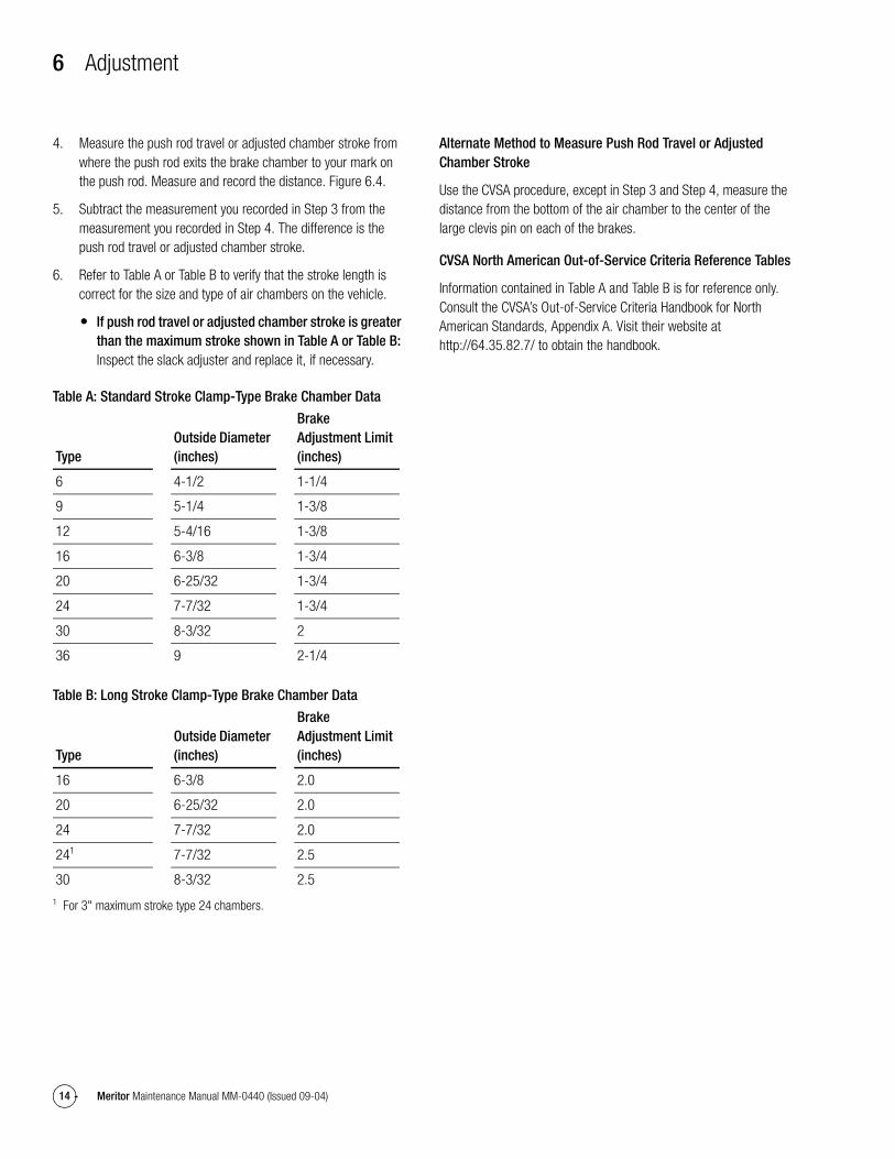
4. Measure the push rod travel or adjusted chamber stroke from where the push rod exits the brake chamber to your mark on the push rod. Measure and record the distance. Figure 6.4.
5. Subtract the measurement you recorded in Step 3 from the measurement you recorded in Step 4. The difference is the push rod travel or adjusted chamber stroke.
6. Refer to Table A or Table B to verify that the stroke length is correct for the size and type of air chambers on the vehicle.
� If push rod travel or adjusted chamber stroke is greater than the maximum stroke shown in Table A or Table B: Inspect the slack adjuster and replace it, if necessary.
Table A: Standard Stroke Clamp-Type Brake Chamber Data
Table B: Long Stroke Clamp-Type Brake Chamber Data
Alternate Method to Measure Push Rod Travel or Adjusted Chamber Stroke
Use the CVSA procedure, except in Step 3 and Step 4, measure the distance from the bottom of the air chamber to the center of the large clevis pin on each of the brakes.
CVSA North American Out-of-Service Criteria Reference Tables
Information contained in Table A and Table B is for reference only. Consult the CVSA’s Out-of-Service Criteria Handbook for North American Standards, Appendix A. Visit their website at http://64.35.82.7/ to obtain the handbook.
TypeOutside Diameter (inches)
Brake Adjustment Limit (inches)
6 4-1/2 1-1/4
9 5-1/4 1-3/8
12 5-4/16 1-3/8
16 6-3/8 1-3/4
20 6-25/32 1-3/4
24 7-7/32 1-3/4
30 8-3/32 2
36 9 2-1/4
TypeOutside Diameter (inches)
Brake Adjustment Limit (inches)
16 6-3/8 2.0
20 6-25/32 2.0
24 7-7/32 2.0
241
1 For 3" maximum stroke type 24 chambers.
7-7/32 2.5
30 8-3/32 2.5

7 Reline the Brakes
15Meritor Maintenance Manual MM-0440 (Issued 09-04)
7 Reline the BrakesHazard Alert MessagesRead and observe all Warning and Caution hazard alert messages in this publication. They provide information that can help prevent serious personal injury, damage to components, or both.
WARNINGTo prevent serious eye injury, always wear safe eye protection when you perform vehicle maintenance or service.
ASBESTOS AND NON-ASBESTOS FIBERS WARNING
Some brake linings contain asbestos fibers, a cancer and lung disease hazard. Some brake linings contain non-asbestos fibers, whose long-term effects to health are unknown. You must use caution when you handle both asbestos and non-asbestos materials.
Reline the Brakes
CAUTIONReline the brakes when the lining thickness is 0.25-inch (6.3 mm) at the thinnest point. The rivets or bolts must not touch the drum. Damage to components will result.
Use the lining material specified by the vehicle manufacturer. This will help to ensure that the brakes perform correctly and meet Department of Transportation (DOT) performance regulations.
Always reline both wheels of a single axle and all four wheels of a tandem axle at the same time. Always install the same linings and drums on both wheels of a single axle and all four wheels of a tandem axle. It is not necessary that the front and rear axles have the same linings and drums.
NOTE: The primary linings must be installed onto the primary shoe. The first shoe past the cam in the direction of wheel rotation is the primary shoe. Figure 7.1. The primary shoe can be either at the top or the bottom position, depending on the location of the cam. If the cam is behind the axle, the top shoe is the primary shoe. If the cam is in front of the axle, the bottom shoe is the primary shoe.
Figure 7.1
Installing Linings with Rivets
1. Check to ensure that the lining and shoe contact faces are clean.
2. Align the rivet holes in the lining with the rivet holes inthe shoe.
Figure 7.1
WHEEL ROTATION WHEEL ROTATION
RIGHT WHEEL ROTATION
CAM IN FRONT OF AXLECAM BEHIND AXLE
LEFT WHEEL ROTATION
WHEEL ROTATIONWHEEL ROTATION
CAM BEHIND AXLECAM IN FRONT OF AXLE
4000375a

7 Reline the Brakes
16 Meritor Maintenance Manual MM-0440 (Issued 09-04)
NOTE: Verify that the rivets are the correct body diameter, head size and shape, length and material.
3. Install the rivets into the rivet holes following the correct sequence. Figure 7.2.
Figure 7.2
A gap of 0.10-inch (0.25 mm) maximum is acceptable between the shoe and linings along the side and ends of the assembly, except between the double web. A 0.025-inch (0.64 mm) gap is acceptable between the webs. Figure 7.3.
Figure 7.3
Installing Linings with Bolts
NOTE: The same procedures must be followed with bolted linings as with riveted linings. New lock washers must be used during installation.
1. Check to ensure that the lining and shoe contact faces are clean.
2. Align the bolt holes in the lining with the holes in the shoe.
NOTE: Verify that the bolts are the correct body diameter, head size and shape, length and material.
3. Install the bolts and lock washers into the bolt holes following the correct sequence. Figure 7.2.
� Tighten 3/8-inch diameter brass bolts to 220-280 lb-in or 18-23 lb-ft (24.8-31.6 N�m). @
� Tighten 1/4-inch diameter brass bolts to 80-100 lb-in or 7-8 lb-ft (9-11.3 N�m). @
Oversize Drums
CAUTIONDo not operate the vehicle with the brake drum worn or machined beyond the discard dimension stamped on the drum. The brake system may not operate correctly if the drums are worn or machined beyond the discard dimension and cause serious personal injury or damage.
To compensate for the worn or refaced drums, X (1/16-inch oversize) and XX (1/8-inch oversize) brake linings are supplied by the lining manufacturers.
Figure 7.2
Figure 7.3
4004502a
8
9
12
11
9
10
12
8
5
4
1
2
36
73
2
1
45
6711
10
4004502a
8
9
12
11
9
10
12
8
5
4
1
2
36
73
2
1
45
6711
10
8 Maintenance
17Meritor Maintenance Manual MM-0440 (Issued 09-04)
8 MaintenanceHazard Alert MessagesRead and observe all Warning and Caution hazard alert messages in this publication. They provide information that can help prevent serious personal injury, damage to components, or both.
WARNINGTo prevent serious eye injury, always wear safe eye protection when you perform vehicle maintenance or service.
During lubrication procedures, if grease flows from the seal near the camshaft head, replace the seal. Remove all grease or oil from the camshaft head, rollers and brake linings. Always replace linings contaminated with grease or oil, which can increase stopping distances. Serious personal injury and damage to components can result.
ASBESTOS AND NON-ASBESTOS FIBERS WARNING
Some brake linings contain asbestos fibers, a cancer and lung disease hazard. Some brake linings contain non-asbestos fibers, whose long-term effects to health are unknown. You must use caution when you handle both asbestos and non-asbestos materials.
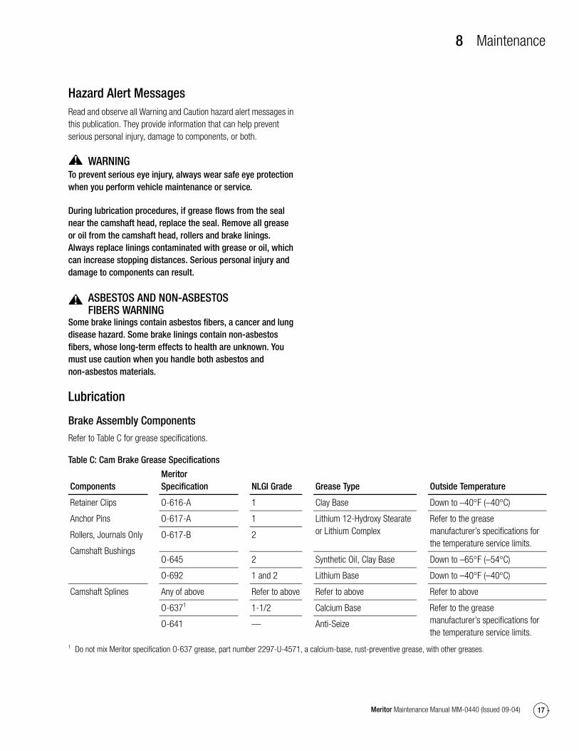
Lubrication
Brake Assembly Components
Refer to Table C for grease specifications.
Table C: Cam Brake Grease Specifications
ComponentsMeritor Specification NLGI Grade Grease Type Outside Temperature
Retainer Clips
Anchor Pins
Rollers, Journals Only
Camshaft Bushings
O-616-A 1 Clay Base Down to –40°F (–40°C)
O-617-A 1 Lithium 12-Hydroxy Stearate or Lithium Complex
Refer to the grease manufacturer’s specifications for the temperature service limits.
O-617-B 2
O-645 2 Synthetic Oil, Clay Base Down to –65°F (–54°C)
O-692 1 and 2 Lithium Base Down to –40°F (–40°C)
Camshaft Splines Any of above Refer to above Refer to above Refer to above
O-6371
1 Do not mix Meritor specification O-637 grease, part number 2297-U-4571, a calcium-base, rust-preventive grease, with other greases.
1-1/2 Calcium Base Refer to the grease manufacturer’s specifications for the temperature service limits.
O-641 — Anti-Seize

8 Maintenance
18 Meritor Maintenance Manual MM-0440 (Issued 09-04)
Camshaft Bushings
Meritor recommends that you install new camshaft bushings whenever you install a new camshaft.
Lubricate through the fitting on the bracket or spider until new grease flows from the inboard seal.
Rollers and Anchor Pins
When you disassemble the brake, or when necessary, lubricate the anchor pins and rollers where these parts touch the brake shoes.
Do not allow grease to contact the area of the roller that touches the camshaft head. Figure 8.1.
Figure 8.1
Slack Adjuster
Inspect and lubricate the automatic slack adjuster according to one of the schedules below. Use the schedule that requires the most frequent inspection and lubrication, and whenever you reline the brakes. Refer to Table D for grease specifications.
� Vehicle manufacturer’s schedule
� Fleet’s schedule
� Every six months
� A minimum of four times during the life of the linings
Table D: Automatic Slack Adjuster Grease Specifications
Figure 8.1
4000365c
BRAKE SHOEROLLER
Lubricatehere only.
BRAKE SHOEANCHOR PIN
Lubricateentirely.
Do not lubricate here.
Components Meritor Specification NLGI Grade Grease Type Outside Temperature
Automatic Slack Adjuster O-616-A 1 Clay Base Down to –40°F (–40°C)
O-645 2 Synthetic Oil, Clay Base Down to –65°F (–54°C)
O-692 1 and 2 Lithium Base Down to –40°F (–40°C)
Clevis Pins Any of above Refer to above Refer to above Refer to above
O-6371
1 Do not mix Meritor specification O-637 grease, part number 2297-U-4571, a calcium-base, rust-preventive grease, with other greases.
1-1/2 Calcium Base Refer to the grease manufacturer’s specifications for the temperature service limits.
O-641 — Anti-Seize

8 Maintenance
19Meritor Maintenance Manual MM-0440 (Issued 09-04)
Anti-Seize Compound
Use anti-seize compound on the clevis pins of all automatic slack adjusters.
For a conventional automatic slack adjuster, use anti-seize compound on the slack adjuster and camshaft splines if the slack adjuster gear does not have a grease groove and holes around its inner diameter.
Intervals
Applications
On-Highway
Q Plus™, Cast Plus™ and Q Series brakes, for every 100,000 miles (160 000 km) or every six months, whichevercomes first.
“P” Series brakes, for every 50,000 miles (80 000 km) or every six months, whichever comes first.
Off-Highway
At least every four months when you replace the seals and reline the brakes.
Every two weeks during the first four-month period, inspect for hardened or contaminated grease and for the absence of greaseto help determine lubrication intervals.
Lubricate more often for severe-duty applications.
Specialty
Lubricate every six months, at each reline or every 10,000 miles(16 000 km).
Adjust the Brakes
NOTE: Adjust the wheel bearings before you adjust the brakes.
Clean, inspect and adjust the brakes every time you remove a wheel hub.
Adjust the brakes when the chamber stroke exceeds CVSA limits. Refer to Section 6.
Adjust the brakes as frequently as necessary for correct operation.
Check for correct lining-to-drum clearance, push rod travel and brake balance.
Reline the Brakes
CAUTIONReline the brakes when the lining thickness is 0.25-inch (6.3 mm) at the thinnest point. The rivets or bolts must not touch the drum. Damage to components will result.
Meritor recommends that you replace the springs, rollers, camshaft bushings and anchor pins at each reline.
Reline the brakes when the lining thickness is 0.25-inch (6.3 mm) at the thinnest point.
Replace shoe retainer springs, check the drum, and perform a major inspection when you reline the brakes.
Important Information on Linings and Primary Shoe Locations
Use the Correct Lining Material
Use the lining material specified by the vehicle manufacturer. This will help to ensure that the brakes perform correctly and meet Department of Transportation (DOT) performance regulations.
Also note that the drums and linings on a front axle can be different than drums and linings on a rear axle. Figure 8.2.
Figure 8.2
Single Axles
Always reline both wheels of a single axle at the same time.
Always install the same type linings and drums on both wheels of a single axle.
Figure 8.2
TANDEM AXLES FRONT AXLE
Both wheel ends of each axle musthave identical drums and lining.
4000376a

8 Maintenance
20 Meritor Maintenance Manual MM-0440 (Issued 09-04)
Tandem Axles
Always reline all four wheels of a tandem axle at the same time.
Always install the same type linings and drums on all four wheels of a tandem axle.
Primary Shoe Locations
The first shoe past the camshaft in the direction of wheel rotation is the primary shoe. Figure 8.3. The primary shoe can be either at the top or bottom position, depending on the location of the camshaft.
If the camshaft is behind the axle, the top shoe is the primary shoe.
If the cam is in front of the axle, the top shoe is the primary shoe.
Figure 8.3
Major Overhaul
Perform a major overhaul at every second reline, or as necessary. Replace the shoe return springs. Replace the damaged or worn parts with genuine Meritor parts. Check the components for the following conditions.
� Spiders for distortion and loose bolts
� Anchor pins for wear and correct alignment
� Brake shoes for wear at anchor pin holes or roller slots
� Camshafts and camshaft bushings for wear
� Brake linings for grease on the lining, wear and loose rivets or bolts
� Drums for cracks, deep scratches or other damage
Inspection
Before You Return the Vehicle to Service
WARNINGTo prevent serious eye injury, always wear safe eye protection when you perform vehicle maintenance or service.
1. Check the complete air system for worn hoses and connectors. With the air pressure at 100 psi (689 kPa), the brakes released and the engine off, tractor air pressure loss must not exceed two psi (13.8 kPa) per minute. Total tractor and trailer loss must not exceed three psi (20.7 kPa) per minute.
2. Verify that the air compressor drive belt is tight. Air system pressure must rise to approximately 100 psi (689 kPa) intwo minutes.
3. The governor must be checked and set to the specifications supplied by the vehicle manufacturer.
4. Both the tractor and trailer air systems must match the specifications supplied by the vehicle manufacturer.
5. Both wheel ends of each axle must have the same linings and drums. All four wheel ends of the tandem axles also must have the same linings and drums. It is not necessary for the front axle brakes to be the same as the rear drive axle brakes. Figure 8.4.
Figure 8.3
WHEEL ROTATION WHEEL ROTATION
RIGHT WHEEL ROTATION
CAM IN FRONT OF AXLECAM BEHIND AXLE
LEFT WHEEL ROTATION
WHEEL ROTATIONWHEEL ROTATION
CAM BEHIND AXLECAM IN FRONT OF AXLE
4000375a

8 Maintenance
21Meritor Maintenance Manual MM-0440 (Issued 09-04)
Figure 8.4
6. Always follow the specifications supplied by the vehicle manufacturer for the correct lining to be used. Vehicle brake systems must have the correct friction material and these requirements can change from vehicle to vehicle.
7. The return springs must retract the shoes completely when the brakes are released. Replace the return springs each time the brakes are relined. The spring brakes must retract completely when they are released.
8. The air chamber area multiplied by the length of the automatic slack adjuster is called the AL factor. This number must be equal for both ends of a single axle and all four ends of a tandem axle. Figure 8.5.
Figure 8.5
Figure 8.4
Figure 8.5
TANDEM AXLES FRONT AXLE
Both wheel ends of each axle musthave identical drums and lining.
4000376a
AL FACTOR = A x LA = AIR CHAMBER AREAL = LENGTH OF SLACK ADJUSTER
“A”
“L”
4000377a

9 Specifications
22 Meritor Maintenance Manual MM-0440 (Issued 09-04)
9 SpecificationsTorque Specifications
Table E: Brake Mounting Bolts
Table F: Air Chamber Mounting, Grade 8 Nuts and Hard Flat Washers
Figure 9.1
PUSH ROD LOCKNUT (1)0.625"-18 Thread25-50 lb-ft (34-68 N·m)
0.500"-20 Thread20-30 lb-ft (27-41 N·m)
Add camshaft spacing washers to provide no
more than 0.060" (1.52 mm) end play.
CAM BRACKET MOUNTING (4)0.500"-13 Thread
Grade 8 = 90-120 lb-ft (122-163 N·m)Grade 5 = 65-100 lb-ft (88-136 N·m)
0.625"-18 ThreadPlain nut = 150-190 lb-ft (203-258 N·m)Locknut = 130-165 lb-ft (176-224 N·m)
AIR CHAMBER MOUNTING (2)Add camshaft spacingwashers so that slack
adjuster is alignedwith air chamber clevis.
GREASE FITTING (1)(SOME MODELS)
1/8" Dryseal3-5 lb-ft (4-7 N·m)
BRAKE MOUNTING BOLTS
Grade 8 bolts with locknuts and twohardened washers on each bolt.
HOLD DOWN CLIP (2)
(SOME MODELS)0.250"-28 Thread
105-135 lb-in (12-15 N·m)
DUST SHIELDMOUNTING (4) or (6)
(SOME MODELS)0.312"-18 Thread
12-20 lb-ft (16-27 N·m)
.375"-16 ThreadGrade 8 = 30-50 lb-ft (41-68 N·m)Grade 5 = 25-35 lb-ft (34-47 N·m)
ANCHOR PIN SET SCREW (2)
(SOME MODELS)0.375"-16 Thread10 lb-ft (14 N·m)
MINIMUM
ANCHOR PIN (2)
(T BRAKE ONLY)0.750"-16 Thread
185-350 lb-ft (250-474 N·m)
(15 X 4 Q BRAKE ONLY)325-375 lb-ft (441-509 N·m)
4004505a
Bolt Size, Grade 8 Torque, lb-ft (N�m)
7/16″-20 60-75 (81-102)
1/2″-20 85-115 (115-156)
9/16″-18 130-165 (176-224)
5/8″-18 180-230 (244-312)
Chamber Size 9 12 16 20 24 30 36 Spring Chamber
Bendix 20-30 lb-ft (27-41 N�m) 30-45 lb-ft (41-61 N�m) 45-65 lb-ft (61-88 N�m) 65-85 lb-ft (88-115 N�m)
Haldex 35-50 lb-ft (48-68 N�m) 70-100 lb-ft (95-136 N�m)
MGM 35-40 lb-ft (48-54 N�m) 133-155 lb-ft (180-210 N�m)
Anchorlok/Haldex — 130-150 lb-ft (177-203 N�m)

Printed in USA
Copyright Issued 09-04ArvinMeritor, Inc. Maintenance Manual MM-0440
Meritor Heavy Vehicle Systems, LLC2135 West Maple RoadTroy, MI 48084 USA800-535-5560arvinmeritor.com
2004(16579/24240)