maintenance manual cec/imc digital audio … · lbi-38938 maintenance manual cec/imc digital audio...
TRANSCRIPT

LBI-38938
MAINTENANCE MANUAL
CEC/IMC DIGITAL AUDIO SWITCHINSTALLATION, SET-UP AND TROUBLESHOOTING
TABLE OF CONTENTS
Page
GENERAL .........................................................................................................................................5
INSTALLATION ...............................................................................................................................5FLOOR PLAN ............................................................................................................................5EQUIPMENT ROOM GROUNDING ....................................................................................... 5AC POWER AND UPS EQUIPMENT....................................................................................... 5IN-CABINET DC POWER CABLES ........................................................................................ 5LOCAL BUS CABLES ...............................................................................................................6INTER- AND INTRA-RACK CABLES ..................................................................................... 6TERMINATOR BOARDS .......................................................................................................... 6CONCENTRATOR CARD CABLES ........................................................................................ 6EXTERNAL CONNECTIONS ................................................................................................... 6
Telco Cables...........................................................................................................................6Concentrator Card Pin-Outs................................................................................................... 6External Cable Length And Shielding.................................................................................... 7Telephone Lines.....................................................................................................................73002 Data Grade Phone Line Specifications........................................................................... 7
AUXILIARY I/O OPTION MSDE3U ........................................................................................ 7CABLE INTERCONNECTION FIGURES ............................................................................... 8
POWER-UP PROCEDURE..............................................................................................................8
CONTROLLER BOARD LIVE INSERTION PROCEDURE ......................................................... 19
SET-UP PROCEDURE......................................................................................................................20STEP 1 - INITIAL CONFIGURATION ..................................................................................... 20
A. CEC/IMC Manager Users................................................................................................20B. MOM Parameters............................................................................................................20
Set Baud Rates..........................................................................................................20Disable Data Logging...............................................................................................21Enable/Disable Printer Status.................................................................................... 21Disable Redundant Clocks........................................................................................ 21Disable Unit Logout Timers...................................................................................... 21
C. System Time And Date....................................................................................................21STEP 2 - SYSTEM MANAGER WIDE AREA CONFIGURATION ....................................... 21
A. Group Call Parameters....................................................................................................21Wide Area Enable/Disable........................................................................................ 21Automatic Tracking Enable/Disable......................................................................... 21Confirmed Call Enable/Disable................................................................................. 22Valid Site Mask Enable/Disable................................................................................ 22Forced Site Mask Enable/Disable.............................................................................. 22
B. Individual Call Parameters..............................................................................................22Wide Area Enable/Disable........................................................................................ 22Automatic Tracking Enable/Disable......................................................................... 22Confirmed Call Enable/Disable................................................................................. 22
1

LBI-38938
TABLE OF CONTENTS (Continued)
Valid Site Mask Enable/Disable............................................................................... 22Forced Site Mask Enable/Disable............................................................................. 22Home Site Assignment............................................................................................. 22Home Group Assignment......................................................................................... 22
C. Additional Recommendations And Firmware Notes........................................................ 23Patching A Conventional Channel To A Group........................................................ 23Verify MIM Site Assignment Number Matches Site Number.................................... 23Disable Patches/Simul-Selects Before Upload........................................................... 23CEC/IMC Firmware Prior To V.30 .......................................................................... 23
Database Clears At Upload................................................................................ 23Database Tracking Reset After Upload.............................................................. 23Partial Upload (Failed Upload).......................................................................... 23
CEC/IMC Firmware V3.0 (And Later) ..................................................................... 24Defaults To Wide Area And Automatic Tracking .............................................. 24Database Does Not Clear At Upload.................................................................. 24Saves Current Tracking Data............................................................................. 24Default Home Site/Home Group........................................................................ 24CNI/Paging Radio Systems................................................................................ 24
STEP 3 - SYSTEM MANAGER UPLOAD ............................................................................... 24STEP 4 - TDM BUS AND TIME SLOT CONFIGURATION .................................................. 24
A. TDM Bus Configuration................................................................................................. 24B. Time Slot Configuration.................................................................................................. 25C. Reset The CEC/IMC....................................................................................................... 25
LINE LEVEL ADJUSTMENT OVERVIEW ............................................................................ 25Line Level Input Adjustments................................................................................................ 25Line Level Output Adjustments.............................................................................................. 26
STEP 5 - RADIO SYSTEM ("SITE") CONFIGURATION ..................................................... 26A. Input And Output Line Levels......................................................................................... 26
Input Level And ALC Enable/Disable...................................................................... 26Output Level............................................................................................................ 26
B. Channel Control Signalling............................................................................................. 27C. NIM "Sites".................................................................................................................... 27D. Confirmed Call ............................................................................................................... 27
STEP 6 - CONSOLE CONFIGURATION................................................................................. 27A. CIM Channels................................................................................................................. 27
Input Level And ALC Enable/Disable...................................................................... 27B. Console User Profiles...................................................................................................... 28
Configure User Profiles............................................................................................ 28Save User Profiles.................................................................................................... 28Send User Profiles.................................................................................................... 28
C. C3 Modular/Desktop Console.......................................................................................... 29Configure Console Modules..................................................................................... 29Save Console Configuration..................................................................................... 29Send Console Configuration..................................................................................... 29
D. Console Privilege Lists.................................................................................................... 29Configure Privilege Lists.......................................................................................... 29Save Privilege List.................................................................................................... 29Send Privilege List................................................................................................... 29
E. Set-Up At The Consoles.................................................................................................. 29C3 Maestro Consoles................................................................................................ 29
Copyright September 1993, Ericsson GE Mobile Communications, Inc.
2

LBI-38938
TABLE OF CONTENTS (Continued)
C3 Modular/Desktop Consoles................................................................................. 29STEP 7 - DISTRIBUTED MULTISITE / STARGATE CONFIGURATION .......................... 29
A. NIM Channel Configuration ........................................................................................... 29B. NIM Control Link Baud Rate.......................................................................................... 30C. NIM Link-Up.................................................................................................................. 30
STEP 8 - CONVENTIONAL CHANNEL CONFIGURATION ............................................... 30A. VMIM Channel Configuration........................................................................................ 30B. Conventional Channel Programming .............................................................................. 30C. VOX Threshold And Secur-It/ Function/2175 Hz Hold Tone Levels............................ 30D. System Manager Database UploadAnd Console Updating............................................... 31
STEP 9 - CTIS/CTIM CHANNEL VERIFICATION .............................................................. 31STEP 10 - DIGITAL VOICE CHANNEL CONFIGURATION ............................................... 31STEP 11 - EDACS DATA GATEWAY INTERFACE VERIFICATIONS ............................... 32STEP 12 - REQUEST STATUS MONITOR VERIFICATION ................................................ 32STEP 13 - CENTRALIZED ACTIVITY LOGGER CONFIGURATION ............................... 32
A. DIP Switch Settings........................................................................................................ 32B. Interconnect Cable.......................................................................................................... 32
STEP 14 - LOGGING RECORDER CONFIGURATION ........................................................ 32STEP 15 - AUXILIARY I/O CONFIGURATION ..................................................................... 33
A. Aux. Input Connections .................................................................................................. 33B. Optocoupler Aux. Output Connections............................................................................ 34C. Relay Aux. Output Connections...................................................................................... 34D. I/O Loop-Back Connections............................................................................................ 34E. Redundant MIM Controller Boards................................................................................. 36F. CEC/IMC Manager Configuration .................................................................................. 36
STEP 16 - CONFIRMED CALL VERIFICATIONS ................................................................ 36STEP 17 - MULTISITE UNIT LOGOUT CONFIGURATION ............................................... 37
A. Multisite Logout Timers................................................................................................. 37B. Enable Timers ................................................................................................................ 37
STEP 18 - WWVB TIME STANDARD CONFIGURATION ................................................... 37A. Netclock II Set-Up.......................................................................................................... 37B. CEC/IMC Manager Set-Up............................................................................................. 37
STEP 19 - E & M SIGNALLING VERIFICATIONS ............................................................... 37STEP 20 - REDUNDANT CLOCK CONFIGURATION .......................................................... 37
TROUBLESHOOTING.................................................................................................................... 38RECOMMENDED TEST EQUIPMENT .................................................................................. 38OVERVIEW ............................................................................................................................... 39
MIM Problems....................................................................................................................... 39CIM Problems....................................................................................................................... 39XLTR Problems..................................................................................................................... 39MOM Problems..................................................................................................................... 39NIM Problems....................................................................................................................... 40VMIM/CIA Rack Problems................................................................................................... 40Tone Generation.................................................................................................................... 40
Confirmation Tones ................................................................................................. 40Alert Tones.............................................................................................................. 40Emergency And Ring Tones..................................................................................... 41Failsoft Tones (Firmware V3.0 And Later Only)...................................................... 41Error Tones.............................................................................................................. 41
3

LBI-38938
TABLE OF CONTENTS (Continued)
SELECTED DIAGNOSTIC PROCEDURES ............................................................................ 41Clearing Controller Board NOVRAM.................................................................................... 41Monitoring Controller Board Serial Data Flow....................................................................... 41Console Re-Initialization........................................................................................................ 42
INITIAL CHECKS ..................................................................................................................... 42SYMPTOM/CAUSE OUTLINE ................................................................................................. 44
Audio Problems After Bus Or Slot Changes........................................................................... 44Unequal Audio Levels............................................................................................................ 45Controller Board "RUN" LED Not On Or Not Blinking......................................................... 45Controller Board "SEC" Or "2ND" LED On.......................................................................... 45Audio Board(s) LEDs Are Not Indicating Normal Operation.................................................. 45Audio Board Not Active Per CEC/IMC Manager's HDLC Statistics....................................... 45No Receive Call Indications At All Consoles.......................................................................... 45No Receive Call Indications At A Single Console................................................................... 46No Receive Audio At All Or Many Consoles.......................................................................... 46No Receive Audio At One Or More (But Not All) Consoles.................................................... 47Transmit Indication Good At Console, But No Receive Audio And No Confirmation/Alert Tones At Console .................................................................................. 47One Or More Consoles Cannot Initiate A Call........................................................................ 48No Transmit Audio From All Consoles.................................................................................. 48No Transmit Audio From A Single Console ........................................................................... 48Wide Area (Multisite) Call Problems...................................................................................... 49No Receive Audio At Console(s) From Conventional Channel............................................... 49No Transmit Audio From Console(s) To Conventional Channel............................................. 49
DIP SWITCH SETTINGSCONTROLLER BOARD 19D903299P1 & P3........................................................................... 51AUDIO BOARD 19D903302P1 & P3......................................................................................... 52CI BOARD 19D903324P1 & P2.................................................................................................. 53CLOCK BOARD 19D903305P1 (Rev. E And Later)................................................................. 54
4

LBI-38938
GENERAL AC POWER AND UPS EQUIPMENT
The CEC/IMC power supply structure in based on theuse of a separate Redundant Power Supply (RPS) unit foreach Card Cage (rack) assembly. Normally, all RPS unitswithin a CEC/IMC cabinet are plugged into two separate acpower strips horizontally-mounted just above the RPS units.The cabinet fan is also plugged to one of the power strips.
The intent of this manual is to guide field installationand test personnel through installation of the Ericsson GECEC/IMC Digital Audio Switch and subsequentmaintenance of the CEC/IMC. Installation, set-up andtroubleshooting information is presented. In addition, therecommended CEC/IMC power-up procedure and theController Board live insertion procedure is included. All cabinets require UPS-protected 120 or 230 Vac (47
to 63 Hz) power sources. Each fully-loaded CEC/IMC CardCage consumes approximately 600 watts; UPS equipmentshould be rated accordingly. In addition, UPS hold-up timeshould meet the specific installation requirements.Typically, the UPS equipment should provide power until aback-up generator can be brought on-line.
INSTALLATION
FLOOR PLAN
In most CEC/IMC installations, the co-locatedCEC/IMC cabinet(s) and GETC uplink cabinet(s) arewithin several feet of each other. This floor plan minimizesthe length of the Telco cables that join the cabinetstogether. Servicing is also eased since the CEC/IMCequipment and the GETC uplink equipment may beconcurrently monitored by a single individual.
AC-line circuit breakers should be located within four(4) feet of the UPS equipment. The breakers can be housedin cable trays above the cabinets or in wall-mountedbreaker boxes.
An entire CEC/IMC cabinet can be protected by asingle UPS rated at 1800 watts minimum. This cabinetrequires only a single ac receptacle and 20-amp circuitbreaker. In this installation, cords from both of the acpower strips are plugged into the UPS. The completecabinet is powered by a single UPS and circuit breaker.UPS or circuit breaker failure would affect the entireCEC/IMC.
Cabinets that contain any optional equipment orderedor planned for the installation should also be included onthe original floor plan. Optional equipment includeslogging recorders, CTIS, DVIU, CAL and RSM equipmentIn addition, floor plan provisions should be made for anyplanned UPS equipment.
Every GETC uplink cabinet has a single power supplyand power cord. A full-loaded GETC uplink cabinet (18GETCs) requires approximately 550 watts of ac power. TheUPS equipment should be rated accordingly.
Punch blocks are usually installed in a dedicatedcabinet or in a closet located near the CEC/IMC equipment.
EQUIPMENT ROOM GROUNDINGIN-CABINET DC POWER CABLESProper grounding techniques should be observed in
order to protect the equipment and service personnel fromlightening and other sources of electrical surges. Allcabinets, lightening arrestors, and associated equipmentshould be connected to a common grounding point that isprovided as a part of the building and/or tower structure.This common grounding point must be within 25 feet of allcabinets (or ground buses) and it should have an impedanceof less than 10 ohms to earth ground.
Power Cable 19D903309P1 provides the dc powerinterconnections between a CEC/IMC Card Cage and itsrespective RPS unit. One cable is required per Card Cageand RPS set. These cables are factory installed and shouldnot normally require any changes during the installationprocess. Simply verify each cable is connected between theBackplane connectors as shown in LBI-38662.
DC power cabling in the GETC uplink cabinets arealso factory installed. Separate interconnections for eachGETC are provided by Power/Phone Line Cable19D902759P1 between the Fuse Panel and the GETCs.Verify the connectors have not come loose during shipmentand they are connected as shown in the applicable assemblydiagrams in LBI-38662.
Insulated 6-gauge copper wire should be used betweeneach cabinet and the common ground point or ground bus.If ground busses are used in a multiple cabinet installation,insulated 4-gauge copper wire should be used between eachground buss and the common ground point. All groundbus-to-common ground point connections should be 25 feetor less.
5

LBI-38938
LOCAL BUS CABLES has two Terminator Boards per rack − one on each end ofthe Backplane.
The Local Bus Cables join digital buses betweenadjacent Card Cage board slots so data can be transferredbetween the Controller Board and Audio Board(s) within agiven interface module. These cables are factory installedand should not normally require any changes during theinstallation process. Repositioning of a Local Bus Cablemay affect board-to-slot positioning and the connectionlocation of the Concentrator Card Cable at the Backplane.Therefore, changes to these cables should not beperformed. Simply verify each cable is connected betweentwo (2) Backplane connectors in accordance with thecustomer-specific system documentation. If necessary, seeLBI-38662 for cable length and assembly details.
CONCENTRATOR CARD CABLES
Each Concentrator Card Cable in the CEC/IMCcabinet interconnects a 24-pin dual-row connector on therear of the Backplane to a Concentrator Card. Twisted-pairshielded cabling is utilized on all of these factory-installedcables. During the installation process, no changes shouldnormally be required. Simply verify none of the cables havebecome loose during shipment and they are all connected inaccordance with the customer-specific systemdocumentation.
In the GETC uplink cabinet, a Concentrator CardCable is required for each GETC installed in the cabinet.These cables interconnect the GETCs to the ConcentratorCard. Up to ten (10) GETCs can be connected to a singleConcentrator Card. Verify all GETCs are properlyconnected to a Concentrator Card as shown in the assemblydiagram in LBI-38662.
INTER- AND INTRA-RACK CABLES
All primary CEC/IMC Backplanes are interconnectedor "daisy-chained" together using multi-conductor ribboncable pairs referred to as "intra-rack" and "inter-rack"cables. Intra-Rack Cables join the Backplanes in anindividual cabinet together and Inter-Rack Cables join theBackplanes between cabinets in a dual-cabinet installation.EXTERNAL CONNECTIONS
The Intra-Rack Cables used in the CEC/IMC areinstalled at the factory. No changes to these cables shouldbe required at installation. Verify each cable has notbecome loose during shipment and it is connected to aBackplane connector as specified by the customer-specificsystem documentation.
Telco Cables
All audio/modem signal and data connections at theCEC/IMC cabinet are made with standard 25-pair Telcocables. These cables have 50-pin Champ (D-style) maleconnectors on both ends with the connectors' pins wired ina straight-through pin-to-pin fashion − pin 1 to pin 1, pin 2to pin 2, etc.. Each cable joins a 50-pin Champ femaleconnector on a Concentrator Card to the external punchblock or other associated equipment. Typically, the punchblocks are located in a separate cabinet or closet. Table 1lists the Telco cable part numbers available from EricssonGE. These Telco cables have each pair individuallyshielded.
If the CEC/IMC uses four (4) or more primary CardCages there will be two (2) Inter-Rack Cables that join theprimary Card Cages together between the two cabinets.These cables pass through openings in adjacent sides of thecabinets which are placed to minimize the Inter-Rack Cablelength. During installation, each cable must be routedthrough the openings and connected to the appropriateBackplane connector in each cabinet as specified by thecustomer-specific system documentation. See LBI-38662for cable length and assembly details. The GETC uplink control data Telco cables are not
routed to the punch blocks. These Telco cables pass directlyto the co-located GETC uplink cabinet(s) and plug into thefemale 50-pin Champ connectors on the ConcentratorCards in the GETC uplink cabinet(s).
TERMINATOR BOARDS
Terminator Boards are plugged onto the appropriateBackplane connectors at the factory. No changes to theseboards should be required at installation. Simply verifyeach board has not become loose during shipment and it isconnected to the Backplane connectors in accordance withthe customer-specific system documentation. The primaryCard Cage "daisy-chain" has Terminator Boards on eachend of the chain − two Terminator Boards per chain. Inaddition, if the CEC/IMC is so equipped, each CIA rack
Concentrator Card Pin-Outs
Since every CEC/IMC installation is unique, the pin-out for the Concentrator Cards can vary greatly from oneinstallation to another. The customer-specific systemdocumentation identifies the Concentrator Card pin-outs.This documentation is included with the CEC/IMC when itis shipped from the factory. It lists unique details about theas-shipped CEC/IMC.
6

LBI-38938
TABLE 1 - TELCO CABLE LENGTHS
assembly diagram in LBI-38662 for connector pin-outdetails.
Punch blocks at the equipment room entry/exit pointshould employ surge-protection for lightening and otherelectrical surges. It is highly recommended that the
PART NUMBER CABLE LENGTH
19D903880P120 5 feet channels for EDACS sites and tone controlled conventionalstations be equipped with ±27-volt clamp protection.However, ±27-volt clamp protection cannot be employed onthe transmit pair to a dc controlled conventional station.This pair may have up to a 135 Vdc potential when a dccontrol current is sent out from the CI Board to theconventional station.
19D903880P121 15 feet
19D903880P122 7 feet
19D903880P123 10 feet
19D903880P124 20 feet
3002 Data Grade Phone Line Specifications19D903880P125 25 feet
19D903880P126 30 feetThe GETC uplink-to-downlink connections require 4-
wire type 3002 data-grade telephone lines or equivalentmicrowave links. In addition, if other remote dataconnections are needed, 4-wire 3002 data-grade lines arealso required for these data links. Equipment requiring3002 data-grade lines if remotely located includes dispatchconsoles, the System Manger and the CEC/IMC Manager.Specifications for type 3002 lines are:
19D903880P127 35 feet
19D903880P128 40 feet
19D903880P129 50 feet
External Cable Length And Shielding
Maximum audio line length is limited only by the lineloss and induced noise. All lines should be twisted-pairs.
• Frequency Response (1 kHz reference)300 - 2700 Hz -2 to +6 dB500 - 2400 Hz -1 to +3 dBLocal audio lines should not require shielded pairs
unless noise is a problem. Shielded pairs are recommendedfor all local lines that carry modem signals.
• Maximum Frequency Error ±5 Hz
• Maximum Net Loss 16 dBTwisted-pair shielded cabling should be used for all
control data connections between a CEC/IMC cabinet andthe external equipment. RS-232 interfaces should belimited to 50 feet and RS-422 interfaces should be limitedto 4000 feet.
• Group Delay (800 - 2400 Hz) 2000 µS
• Minimum S/N Ratio 24 dB
• Special Conditioning (C1, C2, C4) not required
• Special Conditioning (D1) not recom-mendedTelephone Lines
The CEC/IMC audio channels should employ high-quality low-noise phone lines or equivalent microwavecircuits. All audio channels will require 4-wire (duplex)circuits except channels to 2-wire remote controlledconventional stations. Channels that carry modem signals(mobile data or Aegis calls) require 3002-conditionedphone lines.
AUXILIARY I/O OPTION MSDE3U
Every Controller Board has eight (8) bi-level inputlines and eight (8) bi-level output lines that can be used forauxiliary I/O control. This section lists internal CEC/IMCcabinet hardware installation details for auxiliary I/Ooption MSDE3U. The option includes:
All control data uplink/downlink phone lines to/fromEDACS sites, CNI systems, etc. should employ 4-wire3002-conditioned phone lines or equivalent microwavecircuits. Lines of this type guarantee low bit-error datatransfer rates for the 9600 baud GETC uplink/downlinkdata. At the GETC uplink cabinet, phone line connectionsare made at the connector panel mounted near the top rearof the cabinet. This connector panel has two (2) 50-pinChamp connectors (J21 and J22) allowing Telco cable pin-to-pin interconnections to punch blocks. See the cable
• Auxiliary I/O Concentrator Card 19C852221P1
• Concentrator Card Mounting Panel 19D903268P1
• Concentrator Card Cable 19D903628P52
If the CEC/IMC installation includes this option, itmay be beneficial to review the related information in the"SET-UP PROCEDURES" section (Step 15) at this time.
7

LBI-38938
Internal CEC/IMC cabinet aux. I/O hardware installation isas follows:
POWER-UP PROCEDUREThis section describes the recommended CEC/IMC
power-up procedure. It also gives details that can resolveminor problems that may occur during the power-upprocess.
1. Attach Concentrator Card Mounting Panel19D903268P1 to the rear cabinet rail just belowthe existing Mounting Panels. Use the extramounting hardware supplied with Hardware Kit19A130031G12. Blank positions in any existingMounting Panel (the upper three) should not beused to mount the Concentrator Card. Thesepositions should be reserved for future CEC/IMCexpansion.
1. Simultaneously switch on the two (2) RPS unitsthat supply power to the two "end-chain" or "endnode" Card Cages (racks). These Card Cages haveTerminator Boards installed on their Backplanes.The MOM will always be located in one of these"end-chain" racks and the other rack typicallyhouses the LRIM and/or VMIM Controller andAudio Boards. The entire CEC/IMC must bepowered-up simultaneously if it has two (2) or lessCard Cages.
2. Mount the Concentrator Card supplied with theoption onto the CC Mounting Panel that was justinstalled. Connectors J3 and J6 should faceoutwards and J1, J2, J4 and J5 should faceinwards. Use four (4) No. 6-32 x 5/16-inch pan-head screws and four (4) No. 6 lock-washers. Even though a CIA rack has Terminator Boards
on each end, it is not a part of the primaryBackplane structure and it should not be powered-up simultaneously with the "end-chain"Backplanes.
3. A Concentrator Card Cable is required for eachController Board that will handle aux. I/O.Connect a cable to the PA1xx connector on theBackplane that corresponds to the respectiveController Board's Card Cage slot. The PA1xxconnectors are the upper row of 24-pin dual rowheader connectors on the rear of the Backplane.
2. Switch on all other RPS units including the CIArack's RPS units (if present).
3. Verify both switches on all RPS units are turnedon. Also verify the green "STATUS" indicators onthe front panels of all RPS units are illuminated.All "TEMP" indicators should be off.
4. Connect the other end of the cable to appropriateconnector on the Aux. I/O Concentrator Card.Each Aux. I/O Concentrator Card will provideaux. I/O connections for up to four (4) ControllerBoards.
4. All cabinet fans should be tested. With a heat gun,trip each fan's thermostat and verify the fan pullsair up and out of the cabinet.Installation of the Aux. I/O related hardware internal
to the CEC/IMC is now complete. Step 15 in the "SET-UPPROCEDURES" section of this manual details externalpin-outs of the Champ connectors on the ConcentratorCards. Step 15 also includes programming related details.
5. From the CEC/IMC Manager's (MOM PC's)"SYSTEM DISPLAY screen, verify every installedprimary interface module's Controller Board(MIMs, CIMs, XLTRs, NIMs, LRIMs, VMIMs,RIMs, CTIMs, CAMs, DATA, DVIM and theMOM) is active by observing the one- or two-lettersymbol reference. This screen is accessed byselecting "View System/Diagnostics" from themain menu. One or more of the symbol referencesmay be flashing to indicate errors.
CABLE INTERCONNECTION FIGURES
Figures 1 thru 10 in this manual show cableinterconnection details for selected CEC/IMC interfacemodules. Both internal CEC/IMC cabinet interconnectionsand interconnections external of the CEC/IMC cabinet areshown for each interface module. If an interface module does not have a symbol
reference displayed, reset the respective ControllerBoard by pressing the reset button on its frontpanel. At this point, if the "RUN" LED onController Board 19D903299P3 is not lit solid(blinking on 19D903299P1), momentarily removethe board from the from the Backplane and verifyall DIP switch settings. Now, reinsert the boardinto the same slot. If necessary, follow theController Board live insertion procedurepresented in this manual.
The figures are not intended to detail the connectorpin-outs at the Concentrator Cards or the Backplanes. Seethe customer-specific system documentation for connectorpin-out details.
8

CABLE INTERCONNECTIONS LBI-38938
Figure 1 - Typical MIM Cable Interconnections (12 Channels Shown)
9

LBI-38938 CABLE INTERCONNECTIONS
Figure 2 - Typical CIM Cable Interconnections
10

CABLE INTERCONNECTIONS LBI-38938
Figure 3 - Typical XLTR Cable Interconnections
11

LBI-38938 CABLE INTERCONNECTIONS
Figure 4 - MOM Cable Interconnections
12

CABLE INTERCONNECTIONS LBI-38938
Figure 5 - Typical NIM Cable Interconnections (8 Channels Shown)
13

LBI-38938 CABLE INTERCONNECTIONS
Figure 6 - Typical LRIM Cable Interconnections (8 Channels Shown)
14

CABLE INTERCONNECTIONS LBI-38938
Figure 7 - Typical VMIM/CIA Rack Cable Interconnections UsingAudio Concentrator Card 19D903531P1 (8 Channels Shown)
15

LBI-38938 CABLE INTERCONNECTIONS
Figure 8 - Typical VMIM/CIA Rack Cable Interconnections UsingConv. Concentrator Card 19D904337G1 (12 Channels Shown, Standard Configuration)
16

CABLE INTERCONNECTIONS LBI-38938
Figure 9 - Typical VMIM/CIA Rack Cable Interconnections UsingConv. Concentrator Card 19D904337G1 (8 Channels Shown, Main/Standby Configuration)
17

LBI-38938 CABLE INTERCONNECTIONS
Figure 10 - Typical VMIM/CIA Rack Cable Interconnections UsingConv. Concentrator Card 19D904337G1 (8 Channels Shown, Remote Controller Enable/Disable Configuration)
18

LBI-38938
6. Verify the number of "Total Nodes" displayed onthe "SYSTEM DISPLAY" screen matches thenumber of primary interface modules installed inthe CEC/IMC. The node or interface module countincludes all active Controller Boards connected tothe primary GSC bus including the MOM, activeMIMs, CIMs, XLTRs, LRIMs, CTIMs, VMIMs,etc.. Controller Boards with an inactive orsecondary status such as back-up MIM ControllerBoards and the CCI Controller Board in the CIArack do not add to the "Total Node" count.
9. If the CEC/IMC has only one Clock Board, checkthe panel-mounted toggle switches on the boardand verify the "A" clock is off and the "B" clockis on.
If the CEC/IMC has two or more Clock Boards,verify all "A" clocks are off and only one "B"clock is on.
NOTE
If the redundant clock feature can be used, itmay be enabled at a later time in accordancewith the instructions outlined in the "SET-UPPROCEDURE" section.
7. The MOM symbol reference should be "O" in itsFB (hex) reserved position on the "SYSTEMDISPLAY" screen.
The MOM Controller Board and "end" ControllerBoard are referred to as "end nodes" since they arethe far-most Controller Boards on the ends of thedaisy-chained Backplanes. These two (2)Controller Boards have a special DIP switchsetting to identify them as "end nodes". If allinterface modules' symbol references are flashing,verify SW1 position 2 on the "end" ControllerBoard is set to the "1" or "OPEN" position.
10 On each Audio Board, verify the "RUN" LED isflashing, the "RST" LED is off and all other LEDsare on and not flashing.
11. Now verify each Audio Board is active by viewingits status on the "HDLC STATISTICS","CHANNEL B" screen at the CEC/IMC Manager.This screen can be accessed using the functionkeys and the structured window selection methodfrom the "SYSTEM DISPLAY" screen or by usinghot-key "H" from this same screen. Note that thecursor should be on (selecting) the desiredinterface module in the "SYSTEM DISPLAY"matrix before entering the "HDLC STATISTICS","CHANNEL B" screen.
NOTE
If the "end" Controller Board is removed, theController Board closest to it should be set asa temporary end node by setting SW1 position2 to the "1" or "OPEN" position. When thenormal end node is reinstalled, the temporaryend node should be turned off by setting SW1position 2 back to the "0" or "CLOSED"position. The Controller Board must be resetafter each DIP switch change.
CONTROLLER BOARD LIVEINSERTION PROCEDURE
The following Controller Board live insertionprocedure should be followed for all Controller Boards thatdo not have extended power pins on the 96-pin DINconnectors. These earlier Controller Boards include all19D903299P1 boards and 19D903299P3 Rev. B andearlier boards.
8. If an EDACS site uses a redundant MIM, reset theMIM Controller Board whose "SEC" or "2ND"LED is off (the active Controller Board) whilesimultaneously observing the MIM on the"SYSTEM DISPLAY" screen. This MIM shoulddisappear and the back-up MIM should becomeactive and appear in a different location on the"SYSTEM DISPLAY" screen.
1. Place the Controller Board partially in the correctCard Cage slot. DO NOT allow the DINconnectors to make contact with the Backplane atthis time.
If this does not occur, temporarily remove theback-up Controller Board and then reinsert it. Ifnecessary, follow the Controller Board liveinsertion procedure presented in this manual.Reset the back-up Controller Board and repeat thefirst part of this step.
2. Connect either end of Live Insertion Cable19B802612P1 to the DB-9 connector located onthe front panel of the Controller Board beinginserted.
3. Connect the other end of the Live Insertion Cableto the DB-9 connector on any Controller BoardRepeat this step for all redundant MIMs.
19

LBI-38938
that is already "live". The "+5V" LED shouldlight.
• all CEC/IMC boards are installed in the properslots as specified in the configuration print-outsupplied with the equipment
4. Slide the Controller Board being inserted into theCard Cage until its DIN connectors fully engagedinto the Backplane DIN connectors.
• all equipment related to the CEC/IMC is powered-up and operating
5. Disconnect the Live Insertion Cable from bothDB-9 connectors. STEP 1 - INITIAL CONFIGURATION
6. Reset the Controller Board by pressing therecessed reset button on the board's front panel. A. CEC/IMC Manager Users
Up to twelve (12) different users can access theCEC/IMC Manager (MOM PC) at different times. Eachuser is assigned an access level from 1 to 4. The accesslevels are "System Administrator" (level 1), "ConsoleAdministrator" (level 2), "General Maintenance" (level 3)and "User" (level 4). The System Administrator (level 1access) has all CEC/IMC Manager privileges and a User(level 4 access) has minimum privileges. Passwordprotection guarantees only valid users can access theCEC/IMC Manager.
7. Verify the Controller Board is operating byobserving the LEDs on its front panel andobserving the CEC/IMC Manager's "SYSTEMDISPLAY" screen. See LBI-38911 Chapter 3(section 3.5.) for CEC/IMC Manager operatingdetails.
It is recommended that this procedure should be usedfor all Controller Boards if the CEC/IMC has any of theearlier Controller Boards that lack the extended power pins.This will establish a insertion routine and will thus preventaccidental Controller Board damage.
NOTE
SET-UP PROCEDUREThe default user name is "MOMUSER" and thedefault password is "GUEST".
This section summarizes procedures that must beperformed to set-up the CEC/IMC after the hardwareinstallation is complete. Most of the set-up procedures areaccomplished at the CEC/IMC Manager (MOM PC). SeeLBI-38911 for specific CEC/IMC Manager operatingdetails.
Adding users should be the first step in the CEC/IMCManager set-up process. If necessary, additional users canbe added and/or existing users can be deleted at later times.
Select the "User Account Maintenance" from theCEC/IMC Manager's main menu and add all initial users.Assign each user an access level and a password. See LBI-38911 Chapter 3 (section 3.6.) for specific details.
There is also limited information in this sectiondevoted to System Manager set-up procedures andrecommendations. This information highlights specificSystem Manager unit, group and site database settings thatinfluence wide area (multisite) communications. See LBI-38704 for detailed System Manger set-up and operatingprocedures.
B. MOM Parameters
Several MOM Controller Board parameters must beset-up from the CEC/IMC Manager (MOM PC) before anyother CEC/IMC functions are configured. From the mainmenu, select "System Configuration" and then from thesub-menu select "MOM Configuration". Set/verify thefollowing parameters from the "MOMCONFIGURATION" screen (see LBI-38911 section 3.2.1.):
IMPORTANT NOTE
All set-up procedures presented in this manualshould be performed in the order presented.
Set Baud RatesUnless otherwise noted, all of the set-up procedures
assume the following has already been accomplished: Set the MOM's baud rate to 9.6k or 19.2k baud, asrequired. A MOM Controller Board with version 3.0 (andlater) software has "auto-baud" sensing; it does not requirea DIP switch change when the baud rate is changed at theCEC/IMC Manager. The 19.2k baud setting should be usedunless CEC/IMC-to-CEC/IMC Manager cable length isexcessive or induced noise causes data errors. In addition,
• all local and remote audio and control dataconnections are in-place
• all DIP switch settings are set in accordance withthe configuration print-out supplied with theequipment
20

LBI-38938
the 9.6k baud setting may be required if the CEC/IMCManager is remotely located and the full-duplex modemlink does not support 19.2k baud.
STEP 2 - SYSTEM MANAGER WIDE AREACONFIGURATION
The CEC/IMC uses data from the System Manager'sunit (individual) and group databases to control routing ofall wide area (multisite) calls. These databases must be set-up correctly at the System Manager before the SystemManager's data is transferred or "uploaded" to theCEC/IMC. This section highlights the System Managerdatabase settings that will directly influence wide areaoperation and therefore must be set-up very carefully.
Set the MOM's port for the System Manager to therequired baud rate − either 9.6k or 19.2k baud. The SystemManager's baud rate may also need to be changed to matchthis setting. The 19.2k baud setting should be used unlesscable length limits the data rate.
Disable Data Logging
Disable data logging. Data logging of the GSC bustraffic may be enabled at a later time to allow tracing ofcalls and/or lost-call troubleshooting.
With the exception of the "valid site mask" field, allfields described are used by the CEC/IMC for wide areaand console call routing. The valid site mask field is onlyused by the EDACS Site Controllers for unit/groupvalidation.Enable/Disable Printer Status
If a printer is connected to the CEC/IMC Manager(MOM PC), enable printer status. Otherwise, disable theselection.
See LBI-38704 for detailed System Manger set-up andoperating procedures.
A. Group Call ParametersDisable Redundant Clocks
Wide Area Enable/DisableDisable redundant clocks. It may be possible to enablethis option later as outlined in STEP 20. Do not skip toSTEP 20 at this time.
Each group that will operate as a wide area group mustbe enabled for wide area operation at the System Manager.If wide area operation for a group is disabled, a console canonly call the group if the console's "default home site"matches the System Manager's "default home site". Foradditional information on CEC/IMC firmware V3.0 (andlater), review the sub-section entitled "Default HomeSite/Home Group" under the section "CEC/IMCFirmware V3.0 (And Later)" (STEP 2 C).
NOTE
If two or more Clock Boards are installed,corresponding clocks ("A" and "A" for example)on different Clock Boards should not both beturned on via the toggle switches on the frontpanel of the Clock Boards. Only one clock "A" andone clock "B" should be turned on concurrently. Each console's default home site is initially set at the
CEC/IMC Manager (MOM PC). The default home site fora group is set to the default home site of the last unit recordreceived with the group as the default home group. A C3Maestro dispatcher can change a module's default homesite; however, subsequent System Manager uploads willreset it.
Disable Unit Logout Timers
Disable the multisite unit logout timers. This insuresradio units will not be automatically logged off the widearea (multisite) network until these timers can be correctlyset-up as described in STEP 17. Do not skip to STEP 17 atthis time.
Automatic Tracking Enable/Disable
When automatic tracking for a wide area group isenabled, the CEC/IMC will only route wide area groupcalls to radio systems that have at least one unit logged onto the group being called.
C. System Time And Date
Set the system time and date from the "SET SYSTEMTIME" and "SET SYSTEM DATE" screens as described inLBI-38911 Chapter 3 (section 3.2.2.) These screens areaccessed by selecting "System Configuration" from themain menu and "Set System Time and Date" from the sub-menu. Verify the time is entered in a 24-hour format.
If automatic tracking is disabled, the CEC/IMC willonly route wide area group calls to "forced sites". Forcedsites are the radio systems that will always have the widearea group call routed to them.
Enable or disable automatic tracking on a per groupbasis as required.
Set-up details for the WWVB Netclock option areincluded in STEP 18. Do not skip to STEP 18 at this time.
21

LBI-38938
Confirmed Call Enable/Disable Confirmed Call Enable/Disable
The confirmed call option ensures all EDACS radiosystems being called have working channels availablebefore the caller is given a channel access (talk permit)tone. When enabled, a wide area group call is queued untilall applicable sites have assigned a working channel for thecall. Note that even if this confirmed call group setting isenabled, a group call will not confirm on radio systems("sites") that have confirmed call disabled via theCEC/IMC Manager. See STEP 5 D for information onconfirmed call enable/disable on a per "site" basis.
If the confirmed call option for a particular unit isenabled, all individual calls made to and from the unit willbe confirmed. When enabled, a call is queued until thecalled unit has been assigned a working channel. Note thateven if this confirmed call unit setting is enabled, anindividual call will not confirm on radio systems ("sites")that have confirmed call disabled via the CEC/IMCManager. See STEP 5 D for information on confirmed callenable/disable on a per "site" basis.
Enable or disable each unit for confirmed call asrequired.Enable or disable each wide area group for confirmed
call as required. Normally, confirmed call is disabled forCNI and SCAT radio systems. Valid Site Mask Enable/Disable
Valid Site Mask Enable/DisableEach unit that has wide area capability must be
assigned to two (2) or more radio systems ("sites") usingthe valid site mask field. Wide area calls can only be madeif both the caller and the callee are valid (enabled) on thesecondary (receiving) radio system. However, duringfailsoft periods, all units can make wide area calls.
Each wide area group must be assigned to one or moreradio systems ("sites") using the valid site mask field. Foreach wide area group, enable the group for operation on theapplicable radio system(s). A radio system will deny agroup call request to it if the group is not a valid (enabled)group as defined in the valid site mask field.
For each unit, enable or disable each radio system("site") as required.
Forced Site Mask Enable/DisableForced Site Mask Enable/Disable
The CEC/IMC will unconditionally route wide areagroup calls to radio systems that have been enabled in theforced site mask field. Enable or disable the forced sitemask option on a per radio system basis as required.
The CEC/IMC will unconditionally route wide areaindividual calls to all radio systems ("sites") that have beenenabled in the forced site mask field.
For each unit, enable or disable each radio system("site") for forced site operation as required.B. Individual Call Parameters
Home Site AssignmentWide Area Enable/Disable
Each unit must be assigned a home radio system("site") at the System Manger. The CEC/IMC uses thishome radio system as a default when initializing thetracking database. A System Manger upload will reset theCEC/IMC database, tracking the unit to its home siteassignment.
The caller or the callee must have wide area capabilitybefore the CEC/IMC will route a wide area individual call.Therefore, each unit that must have wide area individualcall capability must be enabled for wide area operation atthe System Manager.
If wide area operation for a unit is disabled, a consolecan only call the unit if the console's default home site forthe unit matches the System Manager's default home site.
Home Group Assignment
The CEC/IMC also tracks which group a unit is loggedinto. It uses this group as a default when resetting thetracking database. A System Manager unit database uploadwill reset the unit's current group to the home groupassignment. At the System Manager, assign each unit ahome group.
Automatic Tracking Enable/Disable
When automatic tracking for an individual unit isenabled, the CEC/IMC will only route wide area calls to theradio system that the unit is logged into. If a unit'sautomatic tracking is disabled, the CEC/IMC will onlyroute wide area calls to the unit if the radio system ("site")is a "forced site". Enable or disable each unit for automatictracking as required.
22

LBI-38938
C. Additional Recommendations AndFirmware Notes
Manager database upload. The database is also clearedwhen the CEC/IMC Manager's copy of the database isuploaded. This is done to ensure any deleted entries willhave a clear database entry after the upload.Patching A Conventional Channel To A Group
During an upload, MIMs lose their wide area, forcedand automatic tracking field settings until a new record forthat entry is received. This may disrupt wide areacommunication during the upload.
When a conventional channel is patched to a trunkedgroup, the following database items must be correctly setbefore the patch will function:
• The trunked group must be enabled for wide areaoperation. Database Tracking Reset After Upload
After an upload with firmware releases prior to V3.0,the CEC/IMC resets its tracking data in accordance withthe unit's default home site and default home groupsettings. If a unit was tracking to a different site before theupload, it will have to key or auto-login for a group or sitechange before the CEC/IMC will re-track the unit. Thismay also disrupt wide area communication after the fullupload until the unit has re-established tracking.
• The trunked group must have automatic trackingenabled.
• The conventional channel must be defined as anindividual unit and the LID number must matchthe conventional channel number assigned at theCEC/IMC Manager (MOM PC).
Verify MIM Site Assignment Number Matches SiteNumber If the default home site or home group is incorrectly
set, problems may occur in CNI and paging radio systemsafter a full upload. Communication to CNI and/or pagingunits will be disrupted since the tracking data is lost. It isvery important in this case to set the default homesite/group for a device of this type to the actual MIMassignment number; otherwise, the CEC/IMC will not routewide area or console calls to CNI and/or paging systemssince no units ever log on these radio systems.
A MIM will issue a single warning if its siteassignment number does match the site number reportedfrom the Site Controller. Since the CEC/IMC uses the MIMsite assignment number and not the site number reportedfrom the Site Controller, differences will cause problemswith the forced site mask function. For example, a unit isset valid on site "2" and forced to site "2", but the MIM isactually set for site "1", then the MIM will use site "1" andit may not set the forced site mask correctly. Partial Upload (Failed Upload)
Disable Patches/Simul-Selects Before Upload If the System Manager-to-CEC/IMC link fails during afull System Manager upload with firmware prior to V3.0,database entries for the records that were not received willbe cleared. Consequently, wide area communications forthe cleared units and/or groups will not be possible.
A patch or simul-select uses a special group ID called aSAID. Tracking information for a SAID is built from thetracking information of the entities in the patch/simul-select upon activation. A System Manager full upload whilethe SAID is active will reset the tracking data for the SAID.To avoid problems, all SAIDs should be defined in theSystem Manager's database with wide area and automatictracking enabled. In addition, each SAID should be validon all sites. With these settings, a SAID may lose trackinginformation on an upload like a normal group, butcommunication will resume as units on the SAID are re-tracked.
Before an upload is started, a back-up copy of thecurrent database should be stored in a backup directory onthe CEC/IMC Manager (MOM PC). Then, if the SystemManager link fails the database can be copied back to theCEC/IMC Manager's main directory (C:\MOMPC) and afull unit/group upload from the CEC/IMC Manager willrestore operation. Backup the database as follows:
1. If necessary, exit the CEC/IMC Manager (MOMPC) program.
CEC/IMC Firmware Prior To V.302. Create a backup sub-directory
(C:\MOMPC\BACKUP for example) to store thecurrent (existing) database files in.
CEC/IMC firmware prior to V3.0 requires specialattention to certain database parameters. The following texthighlights the related issues. This firmware is located in thePROMs on the Controller Board. 3. From the DOS prompt in the MOMPC directory,
copy the UNIT_REC.DAT and GRP_REC.DATfiles to the backup directory so they cannot bemodified by the upload routine.
Database Clears At Upload
In firmware releases prior to V3.0, the CEC/IMCcompletely clears its database at the start of a full System 4. Re-enter the CEC/IMC Manager program.
23

LBI-38938
CEC/IMC Firmware V3.0 (And Later) STEP 3 - SYSTEM MANAGER UPLOADCEC/IMC firmware V3.0 (and later) virtually
eliminates the database clearing, tracking reset and partialupload issues in the prior firmware versions as previouslydescribed. This firmware is located in the PROMs on theController Board.
After all System Manager related data is entered thedatabase should be transferred to the CEC/IMC by selecting"System Manager Data" from the CEC/IMC Manager'smain menu and then "Request From System Manager"from the sub-menu. Upload unit, group and site data fromthe System Manager to the CEC/IMC Manager using the"Unit Upload", "Group Upload" and "Site Upload"functions. Upload all data using the "Full Upload" option.See LBI-38911 Chapter 3 (section 3.4.) for specificoperating details.
Defaults To Wide Area And Automatic Tracking
With firmware V3.0 (and later), wide areacommunication can proceed after the Controller Board'sNOVRAM is cleared. Unit and group records default towide area enabled and automatic tracking enabled when theNOVRAM is cleared. Therefore, a System Managerunit/group upload is not required before the unit and groupentities can proceed with wide area communication.
NOTE
Review all information in STEP 2 beforeuploading.
Database Does Not Clear At Upload
Firmware V3.0 (and later) does not clear the databaseat the start of a full System Manager upload. This allowswide area communication to continue during a full upload.At the completion of the upload, any record that did notreceive a new data is deleted. This ensures deleted SystemManager records will be cleared in the CEC/IMC database,as before the upload occurred.
After completing the uploads, the data will bedistributed to all Controller Boards in the CEC/IMC and itwill also be stored in the CEC/IMC Manager's hard disk.Distribution of the data to all Controller Boards preventsCEC/IMC failures in the event of a MOM or CEC/IMCManager failure.
STEP 4 - TDM BUS AND TIME SLOTCONFIGURATION
Saves Current Tracking Data
Firmware V3.0 (and later) saves the current trackinginformation during a full upload. This prevents an uploadfrom interrupting wide area communications to aunit/group until that unit/group keys or logs in.
A. TDM Bus Configuration
The MOM must now be told if the CEC/IMC has theolder 4-bus or the newer 8-bus TDM Audio Boards. Sincethe 4-bus Audio Board is an older design, most CECs/IMCswill use (and will be configured for) 8-bus Audio Boards.
Default Home Site/Home Group
Since firmware V3.0 (and later) does not reset thetracking data on a unit/group upload, the default home siteand home group fields are basically not used. In addition,the console call processing function does not use the defaulthome site. A console call will be routed to a site wheneverthe CEC/IMC has a unit tracked or forced to that site. Thisis true for wide area and non-wide area entities. The defaulthome site is not required to reach a non-wide area entityfrom a console.
NOTES
Since the default number of TDM audio busses iseight (8), this section can normally be bypassedduring set-up of an 8-bus CEC/IMC.
Note that 8-bus Audio Boards will operatecorrectly in a CEC/IMC configured for 4 buses;however, approximately one-half of audio slotscannot be used.
CNI/Paging Radio Systems
Since the CEC/IMC with firmware V3.0 (and later) nolonger logs a unit to its default home site/home group aftera System Manager unit/group upload, any unit or group IDthat will always be located on a particular site (such as aCNI assigned group ID) should be forced to that site. Thisis especially important for CNI or paging systems whereradios only monitor the channel and typically do not key onthe channel. If a radio does not key, it will not be loggedinto the CEC/IMC.
The 4-bus Audio Boards will not routeaudio/modem signals correctly if they are installedin a CEC/IMC configured for 8-buses.
The 8-bus Audio Boards can be identified byAudio Board 19D903302P1 Rev. F (and later)with 344A3561G3 (and later) firmware.
24

LBI-38938
Set the number of TDM audio buses to four (4) or eight(8) by selecting "System Audio Configuration" from themain menu, "TDM Bus and Slot Configuration" from thefirst sub-menu and "System Bus Configuration" from thesecond sub-menu. See LBI-38911 Chapter 3 (section3.1.1.2.) for specific operating details. Again, mostCECs/IMCs will be set for the 8-bus system.
after both the bus and slot configurations have been sentto the MOM.
If the CEC/IMC is equipped with firmware V3.0, thiscan be done automatically from the CEC/IMC Manager byselecting the "Activate TDM Bus Slots" function from the"TDM Bus and Slot Configuration" sub-menu. Selectingthis function will command the MOM to automaticallyreset all other Controller Boards in the CEC/IMC.Send the selected configuration to the MOM by
selecting the "Send Bus Configuration" function. Note thatthis process must be repeated in a 4-bus CEC/IMC if theMOM Controller Board's non-volatile RAM (NOVRAM) iscleared.
LINE LEVEL ADJUSTMENT OVERVIEW
All CEC/IMC line level adjustments are made from theCEC/IMC Manager (MOM PC). These adjustments includeinput and output level adjustments for the radio systemsand input (CIM input) level adjustments for the consoles.
B. Time Slot Configuration
TDM bus time slots must be allocated to all interfacemodules that input audio/modem signals into theCEC/IMC. Consoles, radio systems ("sites") and digitalvoice interface modules must each be allocated one or moreslots. Radio system allocations include all "site"-typeinterface modules (MIM, NIM, VMIM, CTIM, etc.).Digital voice allocations are specifically for DVIMchannels connected to the DVIU equipment. The followingtime slot allocations are recommended:
Line Level Input Adjustments
An audio/modem signal applied to an Audio Board'schannel must be amplified or attenuated to standardreference level before the board digitizes and applies it tothe TDM network. An amplifier and an EEPOT circuitbuilt into each channel is used to accomplish this leveladjustment process. Line level input values must becarefully set (entered) for all active channels; the enteredvalue for a particular channel must match the voice peak(test tone) signal level that is applied to the channel's inputline. This process sets the EEPOT's attenuation level andthus prevents the digitization circuitry from being over orunder driven. Each input level is entered as a dBm level atthe CEC/IMC Manager.
• Consoles should normally be allocated a single slotsince they usually have only one microphone thatcan apply audio to the TDM bus via a CIM.
• Radio systems should be allocated a slot perchannel. For example, a 20-channel EDACS siteshould be allocated 20 slots.
• One digital voice slot must be allocated for eachDVIM-DVIU channel.
For example, if the voice peak input signal level to achannel is -15 dBm the channel's input level should be setto -15 dBm at the CEC/IMC Manager. The Audio Boardwill then amplify a signal applied to this channel by 15 dBso it can be digitized and applied to the TDM bus as a 0dBm reference signal. If a -5 dBm signal was applied tothis channel, the 0 dBm referenced TDM bus would beoverdriven by 10 dBm. Overdriving an input will result inclipped (distorted) audio which may lead to dropping of thechannel at the radio systems.
• EDG interface modules require one time slot foreach EDG transmit data channel needed.
• Since LRIMs do not apply audio to the TDM bus,no LRIM time slot allocations are required.
Configure all time slot allocations by selecting "SystemAudio Configuration" from the main menu, "TDM Bus andSlot Configuration" from the first sub-menu and then"System Slot Configuration" from the second sub-menu.Configure console slots, radio system slots and digital voiceslots using the "Configure Slots" function. Send the slotdata to the MOM using the "Send Slots" function. See LBI-38911 Chapter 3 (section 3.1.1.1.) for details.
Input signal levels should be set to the actual measuredvoice peak (test tone) levels. These settings should not beadjusted to set transmitter deviation. If each input signallevel is carefully measured and set all audio/modem signallevels on the TDM bus will be relatively equal. This willresult in equal output signals from the CEC/IMC regardlessof the origination point. Note that non-wide area radio-to-radio calls are not routed through the CEC/IMC and theyare therefore not influenced by input level settings.
C. Reset The CEC/IMC
No interface modules will receive the new bus and slotsettings stored in the MOM until each one is reset. This canbe done by cycling power or by individually resetting eachinterface module's Controller Board. This should be done
An EDACS MASTR II/IIe/III station is normallyfactory adjusted for a line output of 0 dBm when the stationis receiving an RF signal deviating ±3.0 kHz. The output
25

LBI-38938
line level and the line loss between the station and theCEC/IMC will determine the input level setting for therespective channel.
Disabling a radio system's confirmed call option willdisable confirmation of all calls (individual and group) toit.
Line Level Output Adjustments NOTEEach Audio Board channel output line level to a radio
system ("site") must be set to achieve the desired signallevel at the radio system. Factors that must be consideredinclude the maximum allowable signal level that can beapplied to the line (or MUX), line loss and the signal levelrequired at the radio system. Each channel's output signallevel is adjustable from -25 to +10 dBm at the CEC/IMCManager. Improper output level adjustment may cause aradio system ("site") to drop the RF channel. Normally, theoutput line level signal should not exceed 0 dBm since thisis the maximum allowable signal level for most telephonecircuits.
Many "site"-type interface modules do not actuallyinterface with EDACS sites; however, they areassigned "site" numbers based on the ControllerBoard's site assignment number DIP switchsettings and the System Manager's database siteassignment number. The site assignment numberfor each interface module can easily be obtainedfrom the CEC/IMC Manager's "SYSTEMDISPLAY" screen. Alternately, the siteassignment number can be obtained by reading the5-bit binary equivalent DIP switch setting of SW2on the interface module's Controller Board. SW2position 4 is the most significant bit and SW2position 8 is the least significant bit.
An EDACS MASTR II/IIe/III station is generallyfactory adjusted to provide ±3.0 kHz transmit deviationwith a -10 dBm line input level. This ±3.0 kHz deviationsetting can be changed at the station's control shelf and itmay be necessary to do this if, for example, excessive lineloss prevents the audio from arriving at the station at -10dBm. Consult the station's control shelf maintenancemanual for station deviation adjustment details.
A. Input And Output Line Levels
Input Level And ALC Enable/Disable
From the "SITE CHANNEL CONFIGURATION"screen, set every active channel's input signal level to therequired value. This must be done on a per-channel basisfor each "site" in the CEC/IMC. For example, a 20-channelMIM assigned site number 1 must have all twenty (20)channels set and a 10-channel MIM assigned site number 2must have all ten (10) channels set and an 8-channelVMIM assigned "site" number 3 must have all eight (8)channels set. The valid input signal level range is -25 to+12 dBm. Review the previous section entitled "LINELEVEL ADJUSTMENT OVERVIEW " if necessary.
Since consoles are equipped with volume controls andthey are usually co-located, no output signal leveladjustment is provided for consoles. Volume level at aparticular console's speaker is set by volume adjustment atthe respective module.
STEP 5 - RADIO SYSTEM ("SITE")CONFIGURATION
Channel parameters for all "site"-type interfacemodules must now be configured at the CEC/IMCManager. "Site"-type interface modules include MIMs,NIMs, VMIMs and CTIMs. Parameters include input andoutput signal levels, channel signalling (tone, dc, E & M,none) and ALC enable/disable. A NIM interface moduledoes not require a channel signalling type setting but itdoes require individual enabling of the installed channels.
Enable or disable ALC for each channel as required. IfALC for the channel is disabled, change the input signallevel so it is 1.5 dBm less than the actual input signalvalue. For example, if -10 dBm is actually applied to thechannel, enter -11.5 dBm.
NOTEThese parameters are set-up by selecting "System
Audio Configuration from the main menu, "TrunkedChannel Configuration" from the from the first sub-menuand "Site Channel" from the second sub-menu. This actionwill display the "SITE CHANNEL CONFIGURATION"screen. See LBI-38911 Chapter 3 (section 3.1.2.) forspecific operating details.
DO NOT enable the ALC circuit if Audio Board19D903302P1 controls the channel.
Output Level
Output signal levels are also set from the "SITECHANNEL CONFIGURATION" screen. Set the requiredoutput signal levels for all active channels. As with theinput signal levels, this must be done for each "site" in the
This section also includes details on confirm callenable/disable on a per radio system ("site") basis.
26

LBI-38938
CEC/IMC. Output signal range is -25 to +10 dBm. Reviewthe previous section entitled "LINE LEVELADJUSTMENT OVERVIEW " if necessary.
column. This allows NIM channels to be enabled ordisabled, on a per-channel basis, for distributed multisiteoperation. All NIM "site" channels must be enabled usingthe "Channel Equipped" screen. See LBI-38911 Chapter 3(section 3.1.2.1.1.) for specific details.
NOTE
D. Confirmed CallSince the CI Boards used in the CIA racks haveunity gain channels, all VMIM input and outputlevels should be set in accordance with the linelevel requirements at the respective CI Board.
If confirmed call is enabled for the group/unit at theSystem Manager, a unit initiating a wide area (multisite)call cannot transmit until all calling units have beenassigned working channels or until a timeout periodexpires. A particular radio system ("site") can be disabledfrom the call confirmation process by disabling itsconfirmed call option. Disabling confirmed call for aparticular radio system can prevent delays in the callprocess. For example, it may be desirable to disableconfirmed call for a SCAT radio system since its singlechannel could cause unacceptable delays in confirmed widearea (multisite) group calls. Note that if this confirmed call"site" setting is disabled, unit and group calls to the "site"will not be confirmed even if the confirmed call unit/groupsetting is enabled at the System Manager; the "site"confirmed call setting has priority over the unit and groupsettings.
B. Channel Control Signalling
Channel control signalling type is also set from the"SITE CHANNEL CONFIGURATION" screen. On a perchannel basis, set the required control signalling typeneeded. Selections are "M" for E & M-lead signalling,"Tone" for tone control signalling, "Both" for tone and E &M lead signalling, and "Off" if no signalling is needed.
NOTE
VMIM audio channels should have "ChannelSignalling" set to "Off". Signalling levels for theconventional channels are set in STEP 8. Do notskip to STEP 8 at this time.
Set the confirmed call parameters by selecting "SystemConfiguration from the main menu and then "ConfirmedCall Parameters" from the sub-menu. From the "ConfirmedCall Parameters" screen, disable "sites" that should notparticipate in the call confirmation process. Also,enable/disable the "Auto Confirmed Call Database Fix" asdesired. See LBI-38911 Chapter 3 (section 3.2.9.) forspecific details.
If "Tone", "M" or "Both" is selected, a small windowwill appear allowing enabling/disabling of the channel's2175 Hz notch filter.
NOTE
NOTEDO NOT enable the channel's 2175 Hz notchfilter circuit if Audio Board 19D903302P1controls the channel. At this point in the set-up process, basic wide area
(multisite) calls between EDACS sites can beplaced. This assumes the applicable EDACS sitesare operating, configured, and linked to theCEC/IMC via the MIMs.
This small window also allows setting of the Secur-It/function/hold tone levels on a per Audio Board basis.These tone control sequences, together with the uplink, areused to control the base station. The Secur-It tone level isalways +10 dBm above the function tone and +30 dB abovethe hold tone. Only the Secur-It tone level must be adjusted.Set the Secur-It tone level based on the level required at thebase station and line loss between the CEC/IMC and theconventional base station. The Secur-It tone range is -10dBm to +11 dBm.
STEP 6 - CONSOLE CONFIGURATION
A. CIM Channels
Input Level And ALC Enable/Disable
Since each console normally has a single mic(transmit) line to its respective CIM, usually only a singleinput channel must be set-up for each console. Each activechannel must have its CIM input signal level set and theALC circuit enabled or disabled. Both parameters set-up
C. NIM "Sites"
If NIM "site" channels are displayed on the "SITECHANNEL CONFIGURATION" screen, the "ChannelSignalling" column is replaced with a "Channel Equipped"
27

LBI-38938
the CIM mic audio channel for the respective console. Thevalid range for the input signal is -25 to +12 dBm.
• Minimum Alarm Level − This sets the minimumemergency alarm tone volume level. Emergencytone volume will be the maximum of the modulevolume, mute volume or this setting (whichever isgreater).
Set-up these console channel parameters by selecting"System Audio Configuration" from the main menu,"Trunked Channel Configuration" from the first sub-menuand "Console Channel" from the second sub-menu. Thisaction will display the "CONSOLE CHANNELCONFIGURATION" screen. See LBI-38911 Chapter 3(section 3.1.2.2.) for specific operating details.
• Force Tones to Select Speaker − Enabling thisoption ("Y" in field) will force the confirmationtones (queued, grant, busy, denied) to the selectspeaker. Disabling ("N") it will route theconfirmation tones to the speaker associated withthe console module. Dispatchers that wearheadsets usually prefer the "Y" setting.
NOTE
DO NOT enable the channel's ALC circuit ifAudio Board 19D903302P1 controls the channel. • Beep On Error − Error tones are sounded at the
console if this field is enabled ("Y"). Error tonesnotify the dispatcher that an invalid keystroke hasbeen made.
NOTE• Display Failsoft Indicator (Firmware V3.0 and
later only) − Enabling ("Y") this option will causethe failsoft tones to be sounded at the console. If itis disabled ("N"), no failsoft tones will sound andno failsoft indicators will be displayed.
If ALC for the channel is disabled, change theinput signal level so it is 1.5 dBm less than theactual input signal value. For example, if -10 dBmis actually applied to the channel, enter -11.5dBm.
• Tone Volume Offset (Firmware V3.0 and lateronly) − Console tone volume levels are determinedby subtracting this setting (dBm) from the volumeof the current console module associated with thetone. For example, if the field is set to 5 dBm, thetones will be 5 dBm less than the voice audio atthe current module. Headsets equipped with AGCcircuits may defeat this feature.
B. Console User Profiles
Configure User Profiles
User profiles for each console should now beconfigured. These profiles include various options such asshift supervisor selection (yes/no), default volume settingsfor various modes, unselect speaker audio channel,minimum alarm levels, and caller label vs. LID display. Upto ten (10) user profile shifts can be entered per console.
Configure the console user profiles by selecting"Console Configuration" from the main menu and"Console User Profile" from the sub-menu. This action willdisplay the "CONSOLE USER PROFILECONFIGURATION" screen. See LBI-38911 Chapter 3(section 3.3.1.) for specific details.
Careful attention should be given to the settings thataffect the speaker, volume and tone settings. These settingsinclude:
Save User Profiles• Default Unselect Volume − This field sets thedefault volume of the unselect module/speaker.Unprogrammed individual calls to the console willalso use this setting.
Each user profile configuration should be saved on theCEC/IMC Manager's hard disk using the "Save" option.This option will be automatically activated if an attempt ismade to exit a specific user profile that has not been saved.• Default Speaker − This field sets the default
speaker that unprogrammed individual calls to theconsole will be heard on. Normally, this will be setto "2" so the unprogrammed individual calls willbe heard on the unselect speaker. However,consoles that are equipped with three (3) or morespeakers may use speakers "3" or "4". Theunprogrammed individual call can also be routedto the select speaker by entering a "1" in this field.
Send User Profiles
Each console user profile configuration must now besent to its respective console using the "Send" option. Fromthe "CONSOLE USER PROFILE CONFIGURATION"screen, send each user profile to its console as it is created.
28

LBI-38938
C. C3 Modular/Desktop Console Configure each console's privilege list by selecting"Console Configuration" from the main menu and"Console Privilege List" from the sub-menu. This actionwill display the "CONSOLE PRIVILEGE LIST UPLOAD"screen. See LBI-38911 Chapter 3 (section 3.3.2.) forspecific details.
Configure Console Modules
A special configuration procedure should now beperformed at this point to set-up each C3 Modular/Desktopconsole's Translator. This procedure configures theconsole's module database stored in the TranslatorController Board. Configurable parameters for each moduleinclude module type (trunked or conventional), display type(alphanumeric or fixed) and module present (yes or no).Each C3 Modular/Desktop console can be equipped with upto sixty-four (64) total modules.
Save Privilege List
Each privilege list should be saved on the CEC/IMCManager's hard disk using the "Save List" option. Thisoption will be automatically activated if an attempt is madeto exit a specific console privilege list that has not beensaved.
Configure each C3 Modular/Desktop console moduleat the CEC/IMC Manager by selecting "ConsoleConfiguration" from the main menu and "C3Modular/Desktop Configuration" from the sub-menu. Thisaction will display the "C3 CONSOLECONFIGURATION" screen. See LBI-38911 Chapter 3(section 3.3.3.) for specific details.
Send Privilege List
Send each privilege list to its console as it is createdusing the "Send List" option. This option will transfer thenew privilege list from the CEC/IMC Manager to therespective console.
E. Set-Up At The ConsolesSave Console Configuration
After all necessary parameters are configured for aparticular C3 module, save the console configuration to theCEC/IMC Manager's (MOM PC's) hard disk using the"Save" option.
C3 Maestro Consoles
C3 Maestro consoles should now be set-up. Buildmodules by adding a unit, group or a phone line to eachmodule as required. See the C3 Maestro Operator's Manual,LBI-38660, (section ECR-4489) for specific details.Send Console Configuration
The new configuration for each C3 Modular/Desktopconsole must be sent to the respective Translator ControllerBoard before it will become active. Use the "Send" optionto transfer the new data from the CEC/IMC Manager(MOM PC) to the Translator.
C3 Modular/Desktop Consoles
C3 Modular/Desktop modules must also be built. SeeC3 Modular/Desktop Operator's Manual LBI-38802 forspecific details.
D. Console Privilege Lists NOTE
Configure Privilege Lists At this point in the set-up process, basic console-to-EDACS site communication is possible. Thisassumes the applicable consoles are operating andlinked to the CEC/IMC via the CIMs.
Each console has a privilege list that defines itsspecific privileges. From this list, a CEC/IMC Manager(MOM PC) user can grant or deny a console access tospecific units, groups, conventional channels and/or phonelines. For example, a non-supervisory C3 Maestro consolewhich is denied access to a group will not be able to add thegroup to a module.
STEP 7 - DISTRIBUTED MULTISITE /STARGATE CONFIGURATION
It should be noted that at this point in the set-upprocess, conventional channels cannot be added to theprivilege list for a console; they are not yetdefined/programmed. Conventional channels areprogrammed in STEP 8. They can only be added to theprivilege lists and consoles' modules after they areprogrammed.
A. NIM Channel Configuration
Verify all NIM channels are correctly configured asoutlined in "STEP 5 - RADIO SYSTEM ("SITE")CONFIGURATION ".
29

LBI-38938
B. NIM Control Link Baud Rate Each channel must have its "high-level" and "low-level" characteristics programmed. High-levelcharacteristics include entry of an 8-characteralphanumeric channel alias, the VMIM assignmentnumber, control signal configuration, and 2 or 4-wireselection. Low-level characteristics for each channelinclude specific tone control frequency or dc control currentoffset values. These offset values program the state tablesstored in the CI Boards.
Set the control link baud rate for each NIM in the IMCby selecting "System Configuration" from the CEC/IMCManager's main menu and then "NIM Configuration" fromthe sub-menu. See LBI-38911 Chapter 3 (section 3.2.3.) forspecific operating details. NIM baud rates at all respectiveIMC locations must match before distributed multisitecommunication can occur.
C. NIM Link-UpNOTE
The NIM control links between IMCs can now beverified. Monitor the control link state by viewing the"NIM STATISTICS" screen and observing that the "LinkState" is "UP".
It is recommended that the conventional channelhelp screens and the applicable CEC/IMCManager's programming manual section becarefully reviewed before any conventionalchannels are programmed.Access the "NIM STATISTICS" screen as follows:
Select "View System/Diagnostics" from the main menu andthen highlight the appropriate NIM. Now select the"Diagnostics" option and then select "Statistics" from the"DIAGNOSTICS OPTIONS" window. At this point, select"NIM" from the "STATISTICS DISPLAY OPTIONS"window. See LBI-38911 Chapter 3 (section 3.5.4.2.3.) foradditional details.
To set the high and low-level characteristics for eachchannel, select "System Configuration" from the mainmenu and then select "Program Conventional" from thesub-menu. Set the characteristics for all active channels asrequired. See LBI-38911 Chapter 3 (section 3.2.6.) fordetails.
NOTE C. VOX Threshold And Secur-It/Function/2175 Hz Hold Tone LevelsAt this point in the set-up process, distributed
multisite/StarGate communication is possible.This assumes the IMCs are operating and all theapplicable NIMs are set-up.
The VOX threshold level and the Secur-It, functionand hold tone levels for each conventional channel mustnow be set. This action also sends programminginformation to the CCI Controller Board in the CIA rack,thus programming each CI Board's channel accordingly.
STEP 8 - CONVENTIONAL CHANNELCONFIGURATION
The VOX threshold level adjustment sets the VOXturn-on or trip point. The turn-off point is approximately 4dBm less than the turn-on point. Normally, a channel'sVOX threshold level should be set just above(approximately 3 dBm) the noise floor of the respective lineso the VOX circuit will not trip when the station issquelched. With this setting, the VOX circuit willimmediately trip from the increase in line noise when thestation unsquelches.
The CEC/IMC can support up to sixty-four (64)conventional channels using two (2) VMIMs and two CIAracks. Conventional channel configuration is as follows:
A. VMIM Channel Configuration
Verify all channels for each VMIM have beenconfigured as outlined in "STEP 5 - RADIO SYSTEM("SITE") CONFIGURATION ". Configurable parametersinclude input and output signal levels, channel signallingtype and ALC enable/disable. All VMIM audio channelsshould have "Channel Signalling" set to "Off".
Alternately, the VOX threshold may be set muchhigher than the noise floor (10 dBm or more) so it will onlytrip on voice signals. The VOX circuits have fast attacktimes and a long decay time which prevent turn-off betweenspoken words.
B. Conventional Channel ProgrammingNOTE
CI Board channels used in the CEC/IMC should nowbe programmed. This procedure sends programminginformation to the CCI Controller Board in the CIA rack.The CCI programs each CI Board channel accordingly.
It is not possible to set a channel's VOX thresholdlevel if it has been programmed for CORoperation.
30

LBI-38938
The Secur-It, function and 2175 Hz hold tones areused for conventional base station remote control. Thesetone control sequences are generated by the CI Boardsinstalled in the CIA rack(s). The Secur-It tone level isalways +30 dB above the hold tone and the function tone isalways +20 dB above the hold tone. The 2175 Hz hold tonelevel is the only required setting and it should be set inaccordance with the level required at the conventional basestation and line loss between the CEC/IMC and the basestation. Each conventional channel can be individually setto the required level. If necessary, see the applicable tonecontrol shelf maintenance manual for additional details ontone remote controlled base stations.
been configured as outlined in "STEP 5 - RADIOSYSTEM ("SITE") CONFIGURATION ". Configurableparameters include input and output signal levels, channelsignalling type and ALC enable/disable. All CTIMchannels should have ALC disabled and "ChannelSignalling" set to "Off".
NOTE
At this point in the set-up process, CTIS calls canbe made via the CTIM. This assumes the CTISequipment is operating, configured, and linked tothe CEC/IMC.
To set the VOX threshold and the 2175 Hz hold tonelevels at the CEC/IMC Manager, select "System AudioConfiguration" from the main menu and then select"Conventional Level Adjustment" ("Conv EE POT control"in earlier software) from the sub-menu. Set each channel'sVOX threshold level and 2175 Hz hold tone level asrequired. See LBI-38911 Chapter 3 (section 3.1.3.) fordetails.
STEP 10 - DIGITAL VOICE CHANNELCONFIGURATION
The CEC/IMC supports up to four (4) DVIMs with amaximum of thirty-two (32) channels on each. DVIMchannels are either pooled (dynamically assigned) ordedicated to a particular group. Each DVIM channel shouldbe programmed for either pooled or dedicated operation byselecting "System Configuration" from the main menu and"Program Digital Voice Interface" from the sub-menu.Transfer the data to the DVIM(s) using the "UPLOADDatabase" option. See LBI-38911 Chapter 3 (section 3.2.7.)for details.
D. System Manager Database UploadAnd Console Updating
After all conventional channels have beenprogrammed, perform a System Manager database uploadof the conventional channel information. The uploadshould be performed at the CEC/IMC Manager (MOM PC).
The fundamental DVIM channel characteristics arepermanently set and cannot be changed at the CEC/IMCManager. Input and output signals levels are set to 0 dBm,ALC is always disabled, and channel signalling is alwaysoff.
The privilege lists for all consoles that may requireaccess to conventional channels should now be updated byadding the necessary conventional channels to the lists. SeeLBI-38911 Chapter 3 (section 3.3.2) for specific details.
Each console module can now be "built" or "modified"as required by adding a conventional channel. See theapplicable console operator's manual for details on buildinga module for conventional operation.
NOTE
DVIM channels require Audio Board19D903302P3.
NOTESThe DVIU equipment should now be programmed and
configured in accordance with the DVIU maintenancemanual. Encrypt/Decrypt (E/D) DVIUs should also have avalid cryptographic key loaded into the E/D module.
At this point in the set-up process, basicconventional channel wide area communication ispossible via the VMIM(s) and CIA rack(s). Thisassumes the applicable conventional basestation(s) are operating, configured, and linked tothe CEC/IMC. NOTE
At this point in the set-up process, digital voicecalls can be made via the DVIM. This assumes theDVIU equipment is operating, configured, andlinked to the CEC/IMC.STEP 9 - CTIS/CTIM CHANNEL
VERIFICATION
The CEC/IMC can provide up to twenty (20) channelsfor CTIS equipment. Verify all active CTIM channels have
31

LBI-38938
STEP 11 - EDACS DATA GATEWAYINTERFACE VERIFICATIONS
mode (360k baud) by setting SW1 position 5 to the "0" or"CLOSED" position.
The 60k baud rate may not transfer the CAM/CALdata fast enough during busy periods. This will result indata loss between the CAM and CAL; I-frame errors willbe recorded at the CEC/IMC Manager.
Each EDG channel should be allocated a TDM timeslot as outlined in STEP 5. In addition, EDG channelrelated configurations should be set-up in accordance withthe procedures outlined for C3 Maestro consoles in STEP 6.
B. Interconnect CableSTEP 12 - REQUEST STATUS MONITOR
VERIFICATION The CAM-to-CAL interconnect cable is normallysupplied with the CAL equipment. At the CEC/IMC, thiscable does not connect to a Concentrator Card but instead itconnects directly to the lower connector (24-pin) on therear of the Backplane that corresponds to the CAM slot.
No special CEC/IMC configurations are required forthe RSM equipment. Simply verify the RIM ControllerBoard DIP switch settings are correctly set and connect theRSM-to-RIM cable as specified in the RSM equipmentmanual.
STEP 14 - LOGGING RECORDERCONFIGURATION
STEP 13 - CENTRALIZED ACTIVITYLOGGER CONFIGURATION Up to four (4) LRIMs can be installed in a CEC/IMC
for logging recorder interfacing. Each LRIM can supplythirty-two (32) output channels to logging recorders. Amaximum of sixty-four (64) "modules" can be defined perLRIM. Each module assigns a unit, group, or conventionalchannel to a specific LRIM channel. Volume levels are seton a per module basis. Table 2 lists the volume level outputsettings.
CAL configuration includes setting/verifying theproper DIP switch settings on the CAM Controller Boardand interconnecting the CAM to the CAL computer.
A. DIP Switch Settings
The default or "normal" CAM DIP switch settings areshown in the diagrams near the end of this manual. CAMController Boards are shipped from the factory with thesedefault settings and they usually do not require any changeswith standard CAL/BCU installations. The following textdescribes the optional settings:
The following items should be noted:
• Wide area and non-wide area calls are recorded.
• With respect to modules programmed with anindividual unit or a conventional channel, both thetransmit and receive audio is applied to thelogging recorder channel, not just the transmitaudio.
SW2 position 8 is normally set to "1" or "OPEN" toenable HDLC channel A. If channel A should be disabled,set this switch to "0" or "CLOSED".
• If two (2) or more modules are assigned to a singlechannel, audio summation will occur. Normally,this is not a desirable configuration unless loggingrecorder channels are limited. Up to eight (8)modules can be assigned to a single channel.
SW2 position 7 is normally set to "0" or "CLOSED" todisable HDLC channel B. If channel HDLC B should beenabled, set this switch to "1" or "OPEN". Using channel Bwill require rewiring of the standard CAM-to-CALinterconnect cable.
• Digital voice (Aegis) calls are decoded/decryptedby the DVIU before the LRIM pulls the audio fromthe TDM bus.
SW2 position 5 is normally shipped so the ControllerBoard is set as a DTE device. Change this switch to "1" or"OPEN" if a DCE device setting is required.
To define the required modules for each LRIM, select"System Configuration" from the main menu and thenselect "Program Logging Recorder" from the sub-menu.Define the alias (source) for each module as a unit, group,or conventional channel and set the LRIM channel and thevolume level as required. See LBI-38911 Chapter 3 (section3.2.5.) for details
The CAM-to-CAL HDLC serial link can be set tooperate at 60k or 360k baud. The CAM supplies a clocksignal to the CAL computer so the CAL's synchronousserial port can communicate with the CAM. When SW1position 5 is in the "1" or "OPEN" position the HDLCserial port operates in the low-speed mode (60k baud). Thissetting must be used if excessive CAM-to-CAL cable lengthlimits the transmission rate. Otherwise, use the high-speed After completing each LRIM's module definitions,
send the configuration to the LRIM using the
32

LBI-38938
"REPROGRAM LRIM" option ("PROGRAM ALL" inearlier software").
outputs (Form-A / SPST normally-open contacts).Auxiliary I/O external connections are made at AuxiliaryI/O Concentrator Card 19C852221P1 which is includedwith option MSDE3U.
TABLE 2 - LRIM MODULE VOLUME LEVELSEach I/O line can be individually defined at the
CEC/IMC Manager (MOM PC) for console I/O use. Forexample, an output can be used to turn a siren on when aconsole operator presses a key and an input could be usedfor alarm monitoring. Up to thirty (30) different I/O"events" can be defined at the CEC/IMC Manager.
VOLUMESETTING
OUTPUTLEVEL(dBm)
VOLUMESETTING
OUTPUTLEVEL(dBm)
0 -25.0 17 -0.5
Basically, an output event sets a specific output bit torespond to a console trigger such as a certain button/keyactivation and input events cause a specific message to bedisplayed at the console when the respective input bittransitions to its active state. Each event is assigned to aspecific interface module (MIM, CIM, LRIM, etc.) withinthe CEC/IMC and to a specific auxiliary input or outputline on the interface module's Controller Board. AllController Boards support auxiliary I/O except XLTRController Boards.
1 -14.0 18 0
2 -12.0 19 0.5
3 -10.0 20 1.0
4 -8.0 21 1.5
5 -7.0 22 2.0
6 -6.0 23 2.5
7 -5.5 24 3.0Auxiliary I/O Concentrator Card 19C852221P1
interconnects the auxiliary I/O lines to the external devices.Table 3 lists the I/O bit-to-I/O pin mapping for theConcentrator Card and the Backplane. Also see the tablesin Concentrator Card maintenance manual LBI-38872.
8 -5.0 25 3.5
9 -4.5 26 4.0
10 -4.0 27 5.0
11 -3.5 28 6.0A. Aux. Input Connections
12 -3.0 29 7.0All eight (8) auxiliary inputs on a Controller Board use
optocouplers to connect the input line to themicroprocessor. As shown in Figure 11, the external side ofeach input circuit consists of a 1.2KΩ resistor in series withthe optocoupler's LED.
13 -2.5 30 8.0
14 -2.0 31 9.0
15 -1.5 32 10.0
Every two (2) inputs share a common line that isconnected to the anode side of both optocoupler LEDs. Thecommon connections are listed in Table 3. Normally, thesecommon lines should be connected to an external powersource so 5 - 10 milliamps of dc current will flow throughthe input when the external switch/open-collectoroutput/etc. pulls the input line to ground. Depending uponCEC/IMC input event programming, this may or may notbe the active state.
16 -1.0
NOTE
At this point in the set-up process, loggingrecorder audio is available at the LRIM channels.
STEP 15 - AUXILIARY I/OCONFIGURATION
Most external devices will supply a ground potentialvia a switch, relay or open-collector output to the input linewhen activated. For example, a normally-open SPST switchcan be wired to ground an input line when activated. Whencurrent flows through the input (logic 0 applied) the inputevent is low. In this example, the corresponding input eventfor this line is programmed at the CEC/IMC Manager for aactive low state.
Every Controller Board has eight (8) input lines andeight (8) output lines that can be used for auxiliary I/Ointerfacing to two-state external devices. Controller Board19D903299P1 has eight optocoupler inputs (LED withlimiting resistor) and eight optocoupler outputs (NPN open-collector). Controller Board 19D903299P3 has eightoptocoupler inputs (LED with limiting resistor), fouroptocoupler outputs (NPN open-collector), and four relay
33
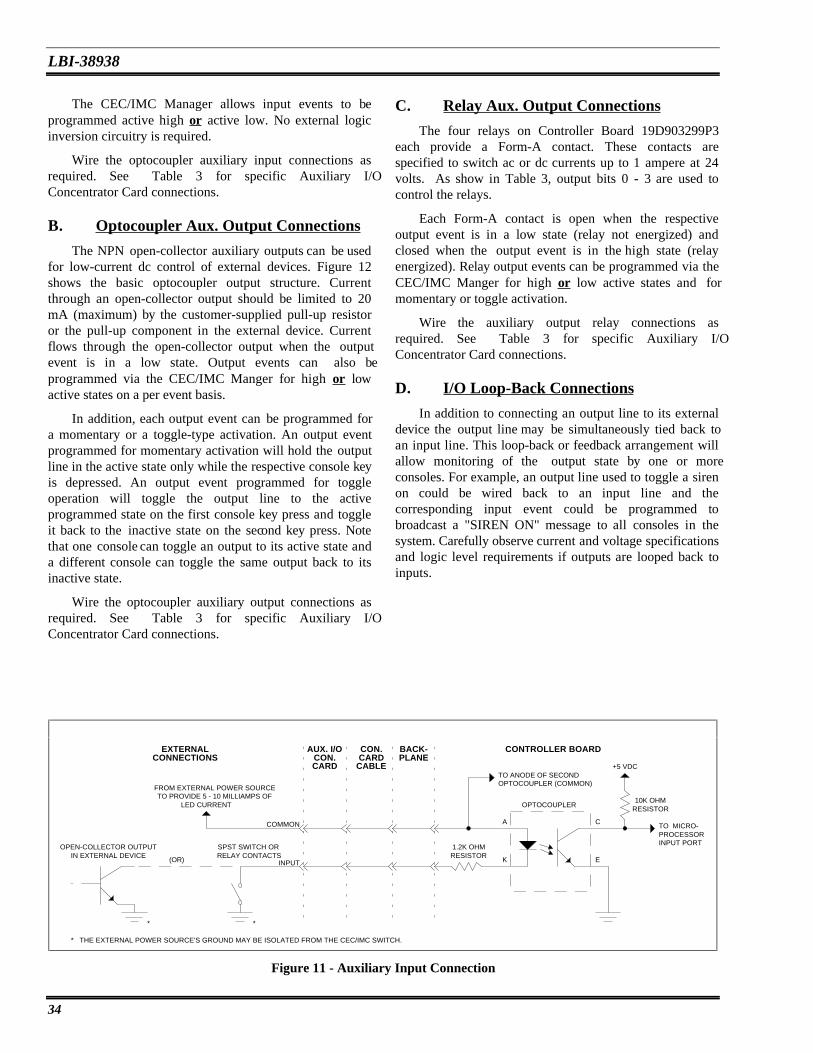
LBI-38938
The CEC/IMC Manager allows input events to beprogrammed active high or active low. No external logicinversion circuitry is required.
C. Relay Aux. Output Connections
The four relays on Controller Board 19D903299P3each provide a Form-A contact. These contacts arespecified to switch ac or dc currents up to 1 ampere at 24volts. As show in Table 3, output bits 0 - 3 are used tocontrol the relays.
Wire the optocoupler auxiliary input connections asrequired. See Table 3 for specific Auxiliary I/OConcentrator Card connections.
B. Optocoupler Aux. Output Connections Each Form-A contact is open when the respectiveoutput event is in a low state (relay not energized) andclosed when the output event is in the high state (relayenergized). Relay output events can be programmed via theCEC/IMC Manger for high or low active states and formomentary or toggle activation.
The NPN open-collector auxiliary outputs can be usedfor low-current dc control of external devices. Figure 12shows the basic optocoupler output structure. Currentthrough an open-collector output should be limited to 20mA (maximum) by the customer-supplied pull-up resistoror the pull-up component in the external device. Currentflows through the open-collector output when the outputevent is in a low state. Output events can also beprogrammed via the CEC/IMC Manger for high or lowactive states on a per event basis.
Wire the auxiliary output relay connections asrequired. See Table 3 for specific Auxiliary I/OConcentrator Card connections.
D. I/O Loop-Back Connections
In addition to connecting an output line to its externaldevice the output line may be simultaneously tied back toan input line. This loop-back or feedback arrangement willallow monitoring of the output state by one or moreconsoles. For example, an output line used to toggle a sirenon could be wired back to an input line and thecorresponding input event could be programmed tobroadcast a "SIREN ON" message to all consoles in thesystem. Carefully observe current and voltage specificationsand logic level requirements if outputs are looped back toinputs.
In addition, each output event can be programmed fora momentary or a toggle-type activation. An output eventprogrammed for momentary activation will hold the outputline in the active state only while the respective console keyis depressed. An output event programmed for toggleoperation will toggle the output line to the activeprogrammed state on the first console key press and toggleit back to the inactive state on the second key press. Notethat one console can toggle an output to its active state anda different console can toggle the same output back to itsinactive state.
Wire the optocoupler auxiliary output connections asrequired. See Table 3 for specific Auxiliary I/OConcentrator Card connections.
FROM EXTERNAL POWER SOURCE
(OR)
OPEN-COLLECTOR OUTPUTIN EXTERNAL DEVICE
SPST SWITCH ORRELAY CONTACTS
+5 VDC
TO MICRO-PROCESSOR
BACK-PLANE
CONTROLLER BOARDAUX. I/OCON.
EXTERNALCONNECTIONS
CON.CARD
CARD CABLE
OPTOCOUPLER
RESISTOR
RESISTOR
1.2K OHM
10K OHM
INPUT PORT
**
* THE EXTERNAL POWER SOURCE'S GROUND MAY BE ISOLATED FROM THE CEC/IMC SWITCH.
INPUT
COMMON
TO ANODE OF SECONDOPTOCOUPLER (COMMON)
A
K E
C
TO PROVIDE 5 - 10 MILLIAMPS OFLED CURRENT
Figure 11 - Auxiliary Input Connection
34

LBI-38938
TABLE 3 - AUXILIARY I/O BACKPLANE AND CONCENTRATOR CARD CONNECTIONS
CNTRLRBD. I/O
LINE
TYPE BACKPLANE CONNECTORS CONCENTRATOR CARDCONNECTORS
*
I/O Bit Optocplr/Relay PA101-PA119,Etc. Pin No.
PA101-PA119,Etc. Pin Name
J1 / J3 J2 / J3 J4 / J6 J5 / J6
I 0 Optocoupler 22 OPT IN A1 22 / 1 22 / 13 22 / 1 22 / 13
(In. Bit 0 & 1 common) 24 OPT IN COM 1 24 / 26 24 / 38 24 / 26 24 / 38
I 1 Optocoupler 19 OPT IN B1 19 / 2 19 / 14 19 / 2 19 / 14
I 2 Optocoupler 21 OPT IN A2 21 / 27 21 / 39 21 / 27 21 / 39
(In. Bit 2 & 3 common) 13 OPT IN COM 2 13 / 3 13 / 15 13 / 3 13 / 15
I 3 Optocoupler 23 OPT IN B2 23 / 28 23 / 40 23 / 28 23 / 40
I 4 Optocoupler 11 OPT IN A3 11 / 4 11 / 16 11 / 4 11 / 16
(In. Bit 4 & 5 common) 7 OPT IN COM 3 7 / 29 7 / 41 7 / 29 7 / 41
I 5 Optocoupler 9 OPT IN B3 9 / 5 9 / 17 9 / 5 9 / 17
I 6 Optocoupler 5 OPT IN A4 5 / 30 5 / 42 5 / 30 5 / 42
(In. Bit 6 & 7 common) 1 OPT IN COM 4 1 / 6 1 / 18 1 / 6 1 / 18
I 7 Optocoupler 3 OPT IN B4 3 / 31 3 / 43 3 / 31 3 / 43
O 0 Relay ** 2 OPT OUT A1 2 / 7 2 / 19 2 / 7 2 / 19
(Out. Bit 0 & 1 common) 6 OPT OUT COM 1 6 / 32 6 / 44 6 / 32 6 / 44
O 1 Relay ** 4 OPT OUT B1 4 / 8 4 / 20 4 / 8 4 / 20
O 2 Relay ** 8 OPT OUT A2 8 / 33 8 / 45 8 / 33 8 / 45
(Out. Bit 2 & 3 common) 12 OPT OUT COM 2 12 / 9 12 / 21 12 / 9 12 / 21
O 3 Relay ** 10 OPT OUT B2 10 / 34 10 / 46 10 / 34 10 / 46
O 4 Optocoupler 14 OPT OUT A3 14 / 10 14 / 22 14 / 10 14 / 22
(Out. Bit 4 & 5 common) 15 OPT OUT COM 3 15 / 35 15 / 47 15 / 35 15 / 47
O 5 Optocoupler 16 OPT OUT B3 16 / 11 16 / 23 16 / 11 16 / 23
O 6 Optocoupler 18 OPT OUT A4 18 / 36 18 / 48 18 / 36 18 / 48
(Out. Bit 6 & 7 common) 20 OPT OUT COM 4 20 / 12 20 / 24 20 / 12 20 / 24
O 7 Optocoupler 17 OPT OUT B4 17 / 37 17 / 49 17 / 37 17 / 49
* Connectors J1, J2, J4 and J5 are the 24-pin dual-row connectors on the Backplane-side of the Concentrator Card. Connectors J3 andJ6 are the 50-pin Champ-type connectors that the external connections are wired to. If, for example, the Concentrator Card Cable isconnected to J1, the Champ connection for input bit 1 is J3 pin 2.
** Open-collector optocoupler-type outputs on Controller Board 19D903299P1.
35

LBI-38938
CONTROLLER BOARD
OPTOCOUPLER
RESISTOR1.2K OHM
TO EMMITTER OF SECONDOPTOCOUPLER (COMMOM)
A
K E
C
FROM EXTERNAL POWER SOURCE
EXTERNAL CONNECTIONSBACK-PLANE
CON.CARD
AUX. I/OCON.CARDCABLE
+5 VDC
FROM MICRO-PROCESSOR
OUTPUT PORT
PULL-UPRESISTOR**
*
TO EXTERNALEQUIPMENT
* THE EXTERNAL POWER SOURCE'S GROUND MAY BE ISOLATED FROM THE CEC/IMC SWITCH. ** THE VALUE OF THE PULL-UP RESISTOR SHOULD LIMIT OPTOCOUPLER TRANSISTOR CURRENT TO 20 MILLIAMPS.
IT IS NOT REQUIRED IF THE EXTERNAL DEVICE HAS A SUITABLE INTERNAL PULL-UP RESISTOR.
(50 VDC MAX.)
Figure 12 - Auxiliary Output Connection
E. Redundant MIM Controller Boards• Console Mask − specific console or consoles
assigned to monitor the input event or control theoutput eventIn a redundant MIM configuration, only the active
MIM Controller Board has control of the auxiliary I/Olines. The output lines on the inactive Controller Boardsremain in the open (high-impedance) state. Therefore,since either board may become the active board,corresponding lines can be wired in parallel between thetwo Controller Boards. For example, the primary ControllerBoard's input line 0 would be paralleled with the secondaryController Boards input line 0 and the primary ControllerBoard's output line 0 would be paralleled with thesecondary Controller Board's output line 0. Whenparalleling inputs, verify the power source can supplysufficient current for both inputs and also verify theswitching device (switch, relay, open-collector output, etc.)can sink sufficient current to pull both inputs to the lowstate.
Configure all required auxiliary I/O events by selecting"System Configuration" from the main menu and "I/OConfiguration" from the sub-menu. See LBI-38911 Chapter3 (section 3.2.4.) for details. Note that the current state(high or low) of the configured I/O events can be monitoredfrom this configuration screen.
With firmware previous to V3.0, a input event textstring of up to twenty-five (25) characters in length can bedefined. Since the C3 Modular/Desktop consoles only have8-character displays, only the first eight in the defined textstring are displayed; all others are truncated.
Firmware V3.0 (and later) allows an input event textstring of only eight (8) characters in length.
NOTEF. CEC/IMC Manager ConfigurationAt this point in the set-up process, the auxiliaryI/O lines will operate as wired and configured.
The following parameters must be set at the CEC/IMCManager (MOM PC) for each auxiliary I/O event that willbe used:
STEP 16 - CONFIRMED CALLVERIFICATIONS
• Type − input or output
• State − high or low active logic state
• Device Type − MIM, CIM, LRIM, etc.The confirmed call option ensures all EDACS radio
systems being called have working channels availablebefore the caller is given a channel access (grant) tone.This software feature is enabled or disabled on a per unitand group basis at the System Manger and on a per radiosystem ("site") basis at the CEC/IMC Manager.
• Device Assignment − interface module assignmentnumber (1 - 32) of the Device Type
• Bit − Controller Board auxiliary I/O bit (0 - 7)assigned to the event
• Message (inputs only) − text string sent to consolewhen the input transitions to the active state
Verify confirmed call for all groups and units has beenenabled or disabled at the System Manger as outlined in
36

LBI-38938
STEP 2 A. and STEP 2 B. respectively. Note that if anySystem Manager confirmed call settings are changed at thispoint, a new System Manger upload will be required.
A. Netclock II Set-Up
Install, wire and configure the hardware items asdescribed in the Netclock documentation and LBI-38911Chapter 5. Special attention should be given to the sectionentitled "5.1.3 Additional Considerations".
Verify confirmed call for all radio systems has beenenabled or disabled as outlined in STEP 5 D.
STEP 17- MULTISITE UNIT LOGOUTCONFIGURATION
B. CEC/IMC Manager Set-Up
The Netclock II software must now be installed on theCEC/IMC Manager. Follow the procedures in LBI-38911Chapter 5.
The multisite unit logout feature can improve callrouting efficiency by logging inactive radio units out of themultisite system. Basically, this prevents wide area(multisite) call routing to inactive units which wouldotherwise unnecessarily delay certain wide area group calls.The multisite unit logout feature has several differentoptions as described in LBI-38911 Chapter 3 (section3.2.8.). It is controlled by the MOM Controller Board.
STEP 19 - E & M SIGNALLINGVERIFICATIONS
Verify E & M signalling for all applicable radiosystems has been configured as described in STEP 5 B andSTEP 8 B of this manual.
A. Multisite Logout TimersSTEP 20 - REDUNDANT CLOCK
CONFIGURATIONThe timer-based multisite unit logout option should
now be set-up if this option will be used. With the timer-based option, each unit has a count-down timer in theMOM that is initialized at radio login and re-initialized ateach radio PTT. The MOM periodically decrements eachtimer and when the timer for a particular unit times-out theCEC/IMC will automatically log the unit off. Each unit'stimer can be programmed in 15-minute increments up to 24hours. Typically, most timers will be set in the 8 to 10-hourrange. Set the timers to the required amount. See LBI-38911 Chapter 3 (section 3.2.8.) for details.
Two (2) identical but completely separate clock circuits − "A" and "B" − on each Clock Board provide redundant(back-up) clocking capability for the Audio Boards. Clockpulse outputs from both circuits are applied to the AudioBoards via the FUTUREBUS transceivers and theBackplane(s). The MOM Controller Board controls clockselection by sending clock select command signals to allother Controller Boards within the CEC/IMC. Clockmonitoring circuitry on the Audio Boards signal the MOMController via their respective Controller Boards if any ofthe selected clock pulses fail.
B. Enable Timers
The MOM timers must be enabled if the timer-basedmultisite unit logout option is used. From the CEC/IMCManager's main menu, select "System Configuration" andthen "MOM Configuration" from the sub-menu. Enable thetimers from this screen.
NOTE
The redundant clock feature should only be used ifthe CEC/IMC is equipped with Audio Boards19D903302P1 Rev. K (and later) and/or19D903302P3. DO NOT enable the redundantclock feature if the CEC/IMC uses19D903302P1 Rev. J or earlier Audio Boards.
STEP 18 - WWVB TIME STANDARDCONFIGURATION
A coordinated universal time standard option isavailable that allows the CEC/IMC to be synchronized toWWVB located in Fort Collins, Colorado. WWVB operateson a frequency of 60 kHz. This option uses the SpectracomNetclock II WWVB receiver which interfaces to theCEC/IMC via a serial port at the CEC/IMC Manager(usually COM2). If the CEC/IMC is equipped with theWWVB option, the Netclock should now be set-up.
The initial start-up or default clock circuit is "B". If theMOM and two other Controller Boards report a "B" clockcircuit problem, the MOM will switch clock operation tothe "A" clock. Similarly, the MOM will also switch back tothe "B" clock if a problem exists with the "A" clock. Thisredundant clock circuit selection can be enabled anddisabled via the CEC/IMC Manager (MOM PC).
Panel-mounted toggle switches on the Clock Boardsallow independent enable/disable control of the
37

LBI-38938
FUTUREBUS transceivers so multiple Clock Boards can beinstalled. Generally, two (2) Clock Boards are installed perCEC/IMC so uninterruptible operation can be achievedwhen a single Clock Board must be removed for servicing.If two Clock Boards are installed and the redundant clockfeature is enabled, the toggle switches are normally set atthe factory as follows:
1. Turn all "B" clocks off at the Clock Board(s). Allclock-related LEDs on all Audio Boards (BCLK,SSYNC, FSYNC, 2175) should turn off and stayoff.
2. At the CEC/IMC Manager (MOM PC), disable theredundant clock feature.
3. Turn one "B" clock on. All clock LEDs on allAudio Boards should turn on.• Clock Board 1 − Clock "A" is turned off and clock
"B" is turned on.If Audio Boards Are Mixed:• Clock Board 2 − Clock "A" is turned on and clock
"B" is turned off. 1. From the CEC/IMC Manager (MOM PC), disablethe redundant clock feature.
With the toggle switches set in this manner, clock "B"on Clock Board 1 will be the active clock when theCEC/IMC is powered-up. If a clock failure occurs, theMOM will switch all Audio Boards to the "A" clock andthus the "A" clock on Clock Board 2 will become the activeclock. Clock Board 1 can then be removed for service andthe "B" clock on Clock Board 2 can be turned on via thetoggle switch so redundant clock operation will continue.
2. If only one Clock Board is installed, turn bothclocks ("A" and "B") on via the panel mountedtoggle switches. If multiple Clock Boards areinstalled, turn all "A" clocks off except for one andturn all "B" clocks off except for one.
3. Clear the MOM Controller Board's non-volatileRAM (NOVRAM). This can be done as follows:Change the MOM Controller Board's DIP switchesto a different interface module type (CIM or MIMfor example), reset the Controller Board and thenwait at least three (3) seconds. Now, change theDIP switches back to the MOM setting and resetthe board again.
If the redundant clock feature will be used, first verifythe toggle switches on the Clock Board(s) are correctly setas previously described. Now, select "SystemConfiguration" from the CEC/IMC Manger's main menuand then "MOM Configuration" from the sub-menu.Enable the redundant clock feature from this screen.
4. From the CEC/IMC Manager, send the TDM busand slot assignments to the CEC/IMC.NOTE
5. Reset each Controller Board by pressing the resetswitch on the front panel. If the CEC/IMC isequipped with firmware V3.0, this can be doneautomatically from the CEC/IMC Manager byselecting the "Activate Bus Slots" option.
If two or more Clock Boards are installed,corresponding clocks ("A" and "A" for example)on the different Clock Boards should never beturned on.
If only a single Clock Board is installed, bothclocks ("A" and "B") should be turned on when theredundant clock feature is enabled. TROUBLESHOOTING
Unless otherwise stated, the troubleshootinginformation presented in this section assumes theCEC/IMC has been correctly installed and set-up asspecified in the previous sections.
If the CEC/IMC is equipped with the earlier AudioBoards (19D903302P1 Rev. J or before), the CEC/IMCmay begin toggling between the two clock circuits if theredundant clock feature is enabled. Errors will be logged atthe CEC/IMC Manager and audio problems will occur thatmay or may not be noticeable. The audio problems are morenoticeable in larger CECs/IMCs. If no backup clock isturned on during the clock toggles, distinct periods of goodaudio then no audio will occur as the CEC/IMC togglesbetween the clocks. To restore correct operation if thisfeature is accidentally enabled with the earlier AudioBoards, perform one of the following procedures:
RECOMMENDED TEST EQUIPMENT
• EDACS Portable Radios − M-PA, M-RK or M-PD(at least two needed for wide area calls)
• Audio (Test Tone) Signal Generator
• Audio Level Meter
• Volt-Ohm Meter or Digital MultimeterIf Audio Boards Are Not Mixed: (19D903302P1 upto Rev. J and no 19D903302P1 Rev. K or later and no19D903302P3 boards)
• Protocol Analyzer − HP 4951 (or equivalent)
38

LBI-38938
• Oscilloscope (50 MHz minimum bandwidth) Failure of a CIM Audio Board will cause loss of audiocommunication at the respective console. However, controlinformation handled by the Controller Board such as"CALL" and "XMT" information which is displayed at theconsole will continue. Failure of a single audio channel willresult in the loss of the respective audio device(s) at theconsole. For example, if the CIM's channel 2 audio outputfails the unselect speaker will not operate.
• CEC/IMC Extender Board 19B802578P1
• Controller Board Test Point Extender19D904176P1
• Live Insertion Cable 19B802612P1
• Controller Board Monitor Cable 19B802286P1and P2
XLTR Problems
OVERVIEW As with CIM Controller Board failures, XLTRController Board failures will also result in complete failureof the respective C3 Modular/Desktop console. Otherconsoles are not affected by the XLTR failure.
MIM Problems
If a MIM does not have a redundant Controller Board,failure of its single Controller Board will result in a loss ofwide area (multisite) and dispatch console communicationwith the respective radio system. This will also be the resultif a failure occurs in the respective GETC uplink/downlinkequipment. Non-wide area calls within the radio systemwill continue normally as controlled by the Site Controller,CNI system, etc. Other radio systems within the wide areanetwork are not affected by the MIM Controller Board orGETC uplink/downlink failure except users in these radiosystems cannot communicate with the users in the failedradio system.
Control data is transferred between the XLTR and theCIM Controller Boards via 2 pairs (one TX and one RX) inthe Concentrator Card Cable. This cable also connects tothe Concentrator Card to transfer the control data into andout of the XLTR to and from the console.
MOM Problems
If the MOM Controller Board completely fails, thefollowing will occur:
• communications between the CEC/IMC and theSystem Manger will be lost
The redundant MIM configuration provides a standbyController Board that will automatically become active if aproblem occurs with the primary Controller Board. Thisautomatic switch-over will also occur if a problem is sensedin the primary GETC uplink/downlink equipment.
• communications between the CEC/IMC and theCEC/IMC Manger (MOM PC) will be lost
• consoles will not be able to perform patch orsimul-select operations
Failure of a MIM Audio Board can cause loss of up tofour (4) audio/modem signal channels between the radiosystem and the CEC/IMC. Wide area and consolecommunication over the lost channels will not be possible.Typically, this failure can be identified by calls beingrouted (via the control data uplink/downlink) but noaudio/modem signal is received.
• EDACS trunking system status (trunked, failsoft 1,failsoft 2) will not be updated at the consoles if astatus change occurs
• other Controller Boards in the CEC/IMC will notbe properly initialized if their NOVRAM iscleared
CIM Problems• redundant MIM switching will not function
• redundant clock feature will not function if it isenabledIf a CIM Controller Board fails all communications
with the respective dispatch console will be lost.Essentially, the console is completely disabled. Otherconsoles are not affected by the single CIM failure.
• redundant GSC feature will not function
• data logging of the calls will not occur
Failure of the computer equipment at the consolelocation or a problem with the control data link between theCIM Controller Board and the console will usually notcompletely disable the console's receive (speaker) audio. Ifthe control data connection at the console is lost, receiveaudio over the select and unselect speakers will remain onthe last selected modules (groups or individuals).
MOM Audio Board failure will result in a loss ofconsole emergency and ring tones. During normaloperation, these tones are continuously applied to severalTDM bus slots specifically reserved for this application.Other Audio Boards in the CEC/IMC extract the tones fromthe slots as needed.
39

LBI-38938
These tones are the only function provided by theMOM Audio Board. If the MOM Controller Board is notoperating correctly when the CEC/IMC is powered-up,these tones will not exist. This will also be the result if theHDLC/HSCX channel B link between the MOM ControllerBoard and the Audio Board is not operating at power-up.The HDLC/HSCX signals are transferred from the MOMController Board to MOM Audio Board via the Local BusCable between the two boards.
tone is generated and it lists the specific tone frequencies,durations and where applicable, the number of repetitions.
NOTE
The tone volume levels may be adjusted on a perconsole basis using the "Minimum Alarm Level"and "Tone Volume Offset" options. These optionsare set in the "CONSOLE USER PROFILECONFIGURATION" screen at the CEC/IMCManager. Large values in the "Tone VolumeOffset" option (only in firmware V3.0 and later)may attenuate the tones to the point where theywill not be heard at the console. See STEP 6 in the"SET-UP PROCEDURE" section for details onthe console user profile settings.
Failure of the MOM Controller Board after the toneinitialization sequence is complete will not usually affectthe Audio Board tone generation. This initializationsequence occurs at power-up.
NIM Problems
Loss of a NIM Controller Board will result in a lack ofdistributed multisite capability between the respectiveIMCs. Similarly, if a NIM Controller Board within aStarGate Controller fails, distributed multisite operationbetween the StarGate Controller and the respective IMCwill be terminated.
Confirmation Tones
Confirmation tones are generated by channel 1 of theCIM's Audio Board. They are sent out to the console whenthe CIM Controller Board receives the radio system'sresponse (from MIM, NIM, VMIM, etc.) to the initialconsole PTT. These tones include the busy, denied, grantand queued tones. Normally, the speaker that aconfirmation tone is routed to (select or unselect) isdetermined by the state of the module containing thegroup/channel/individual being called. However,confirmation tones may be forced to the select speaker atthe CEC/IMC Manager if the "Forced Tones to SelectSpeaker" option is enabled. This option is a part of theconsole user profile configuration. Tone specifications are:
A NIM Audio Board problem may result in a loss of upto four (4) audio/modem channels between the IMCs.Typically, this failure can be identified by distributedmultisite calls being routed (via the control data link) butno audio/modem signal is received at the destination radiosystem or console.
VMIM/CIA Rack Problems
VMIM or CCI Controller Board problems may causeall communications to cease between the CEC/IMC and theconventional base stations connected to the respective CIArack. If this occurs, all conventional channel operations,including patches, will not be possible. In addition, consolecommunications with the conventional stations will notfunction.
• Busy Tone − 500 Hz tone for 80 milliseconds thenno tone for 20 milliseconds; three (3) repetitions
• Denied Tone − 500 Hz tone for 20 milliseconds
• Grant Tone − 1000 Hz tone for 20 milliseconds
Problems with a VMIM's Audio Board or the CI Boardmay cause up to four (4) channels of conventional stationaudio to be lost.
• Queued Tone − 2000 Hz tone for 20 milliseconds
Using the confirmation tones, basic console receiveaudio operation can be verified between the CIM andconsole. If the tones are present at the console, the CIMController Board, most of CIM Audio Board's channel 1output circuitry (to console) and the console receive pathsare good. Simply transmit on a test group or channel andlisten for one of the confirmation tones from the CIMAudio Board. Presence of the confirmation tones alsoindicates the control data link between the CEC/IMC andthe radio system is good.
Since the CI Board generates tone and dc controlsignals for remote base station control, CI Board failuresmay result in a loss of remote conventional base stationcontrol for functions such as transmit keying, ChannelGuard enable/disable, channel switching, etc. In addition, E& M control functions may be lost.
Tone Generation
Knowledge of where various tones are generatedwithin the CEC/IMC network can be a very usefultroubleshooting asset, particularly in regards to audioproblems at the consoles. This section specifies where each
Alert Tones
Alert tones are also generated by channel 1 on theCIM's Audio Board. Each specific tone is generated when
40

LBI-38938
an alert key at the console is pressed with the consoletransmitting. The alert tones are routed to thegroup/channel/individual being called (via the MIM,VMIM, NIM, etc.). Firmware V3.0 (and later) also routesthe alert tones to the console's select or unselect speaker.Tone specifications are:
• Error Tone − 1000 Hz for 40 milliseconds then500 Hz for 40 milliseconds
SELECTED DIAGNOSTIC PROCEDURES
Clearing Controller Board NOVRAM• Alert Tone − 1000 Hz tone; exists for as long asan alert key is depressed with the consoletransmitting
Clear a Controller Board's non-volatile RAM asfollows:
1. Remove the Controller Board.• Pulsed Alert Tone − 1000 Hz tone for 260milliseconds then no tone for 240 milliseconds;exists for as long as a pulsed alert key is depressedwith the console transmitting
2. Change board's DIP switches to a differentinterface module type. For example, change aMIM to a CIM.
• Warble Tone − 1600 Hz for 200 millisecondsthen 2000 Hz for 200 milliseconds; exists for aslong as a warble alert key is depressed with theconsole transmitting
3. Reinsert the Controller Board. Use the liveinsertion procedure if necessary. Now, wait at leastthree (3) seconds so the board will reinitializeitself.
Emergency And Ring Tones 4. Remove the board again.
5. Change the DIP switches back to the originalsettings.
Emergency and ring tones are generated continuouslyby the MOM Audio Board's channels 1 and 2 respectively.The emergency tone is applied to TDM bus 0, slot 0 and thering tone is applied to TDM bus 1, slot 0. Any CIM in theCEC/IMC can extract either tone as required. Tonespecifications are:
6. Reinsert the board again. If necessary, use the liveinsertion procedure.
Monitoring Controller Board Serial Data Flow• Emergency Tone − 500 Hz for 500 milliseconds
then no tone for 500 milliseconds; continuouslygenerated
Serial data flow between a Controller Board and theexternal data device(s) can be easily monitored byconnecting an oscilloscope or protocol analyzer to theappropriate pins at RJ-11 MONitor connector (J3) on theboard's front panel. Serial data coming into (RX) and goingout of (TX) a Controller Board is buffered and applied toJ3. The pin-out for J3 is shown in Table 4. Use ControllerBoard Monitor Cable 19B802286P1 with Controller Board19D903299P1. Use Cable 19B802286P2 with ControllerBoard 19D903299P3.
• Ring Tone − 1000 Hz for 20 milliseconds then500 Hz for 20 milliseconds, twenty (20) repetitionsof this then silent for 1200 milliseconds;continuously generated tone sequence
Failsoft Tones (Firmware V3.0 And Later Only)
Failsoft tones are generated by channel 1 on the CIM'sAudio Board when a MIM notifies the CIM(s) of a sitestatus transition. The CIM channel 1 output applies thetone to the console. Tone specifications are:
The serial data signals at J3 are at RS-232 levels ofapproximately ±12 Vdc referenced to J3 pin 6. It should benoted that there are separate input receivers and outputdrivers that buffer the signals between the external serialdata lines and the modem circuits on the Controller Board;therefore, if an output line driver on the Controller Boardfails, RS-232 serial data signals will continue to appear onthe TX pins at J3.
• Failsoft Tone − 1000 Hz tone for 60 millisecondsthen 500 Hz for 60 milliseconds; eight (8)repetitions
Error TonesUsing an oscilloscope, an output polling signal can be
periodically observed on the TX serial line to the radiosystem. PTT activity will add additional data bits.
Error tones notify the console operator that an invalidkeystroke has been made. For example, an error tonesounds if no module is selected when the PTT key ispressed. These tones are generated by channel 1 on theCIM Audio Board.
41

LBI-38938
"SET-UP PROCEDURE" section of this manualfor specific details.TABLE 4 - RJ-11 MONITOR CONNECTOR J3
7. From the CEC/IMC Manager, perform a SystemManager "site" upload, conventional channelupload and a console upload.
PIN CONTROLLER BD.SIGNAL NAME
SERIAL DATADIRECTION
8. Send the auxiliary I/O configuration from theCEC/IMC Manager to the MOM.
1 Y_TXD0_232_MON MIM to GETC Uplink,CIM to C3 Maestro
Console, MOM to SystemManager, etc. 9. Verify console operation. If a C3 Modular/Desktop
console incorrectly indicates the system is infailsoft mode, reset the respective CIM ControllerBoard.
2 Y_RXD0_232_MON GETC Uplink to MIM,C3 Maestro Console to
CIM, System Manager toMOM, etc.
INITIAL CHECKS3 Y_TXD1_232_MON XLTR to C3Modular/Desktop Console
& MOM to CEC/IMCManager Only
1. Verify all boards are fully inserted into the CardCage slots.
2. Verify all LEDs on all Terminator Boards are lit.If not, troubleshoot the Terminator Board failureor the +5 Vdc external power supply failure beforeproceeding.
4 Y_RXD1_232_MON C3 Modular/DesktopConsole to XLTR &
CEC/IMC Manager toMOM Only
3. At each Clock Board, verify both "PWR" LEDs arelit. This guarantees the fuses on the ClockBoard(s) are good and the +5 Vdc supply power ispresent on that Backplane.
5 none n/a
6 GND (common)
Console Re-Initialization4. Inspect the toggle switches on all Clock Boards.
Only one "A" clock and one "B" should be on.Perform the following procedure if console re-initialization is necessary. This will be required if powerhas been cycled at a console or if some other console failurehas previously occurred.
5. Verify the LEDs on all Controller Boards are intheir normal state as indicated in Table 5.19D903299P1 Controller Boards have red LEDsand 19D903299P3 Controller Boards have greenLEDs. Special attention should be given to theMOM Controller Board's LEDs since all otherController Boards communicate with the MOMController Board. DO NOT clear the NOVRAMon any Controller Board if a problem is suspectedwith the MOM Controller Board. Doing so couldcause a loss of data at the reset Controller Boardwhich may result in loss of operation of theinterface module.
1. Verify power has been restored at the console.
2. Verify correct LED status on all associatedController and Audio Boards. Monitor theCEC/IMC Manager's "SYSTEM DISPLAY"matrix screen and observe the CIM and XLTR (C3Modular/Desktop console only) symbol referencesare present and not flashing.
3. From the CEC/IMC Manager (MOM PC) send theconsole's user profile data to the console.
4. If the console is a C3 Modular/Desktop console,send the its configuration data from the CEC/IMCManager.
NOTE
The IDentify LED does not function onController Board 19D903299P1. Inaddition, this LED remains lit on an XLTRusing Controller Board 19D903299P3 withPROM firmware 344A3569/3570G3 andearlier; it cannot be enabled to blink via theCEC/IMC Manager.
5. Send the console's privilege list data from theCEC/IMC Manager.
6. If the console's input channel (mic audio) levelsetting is not the same as the default setting of 0dBm, reset the input level setting via theCEC/IMC Manager as required. See STEP 6 in the
42

LBI-38938
and/or the drawings at the end of this manualfor detailsIf LEDs on any Controller Board indicate
problems, reset the board and monitor the LEDsagain. If the problem continues, remove the boardand verify the following:
• firmware (PROMs U58 and U59) part numberis correct − the XLTR firmware (U58 =344A3569 and U59 = 344A3570) is differentfrom all other firmwares (U58 = 344A3567and U59 = 344A3568)
• all fuses are good
• DIP switches are correctly set − see thecustomer-specific system documentation • firmware (PROMs U3, U58 and U59) chip
insertion − verify none of the PROMs are inbackwards and each pin is fully inserted intoits respective hole
TABLE 5 - CONTROLLER BOARD LEDINDICATIONS
LEDNO.
FRONTPANELNAME
NOR-MAL
STATE
NOTES
1RST*
RUN**
Off
On
Off = board not in resetcondition;On = processors inoperation
2* ERR Off Off = no errors
3* RUN Blinking Blinking = processorsin operation
4 WDEN On On = watch-dog circuitis enabled
5 -12V On On = -12 Vdc on-boardpower supply & -15Vdc ext. power supplypresent
6 +12V On On = +12 Vdc on-board power supply &+15 Vdc ext. powersupply present
8 ID OnorOff
Blinks when boardplaced in identify modefrom CEC/IMCManager (MOM PC)
9 +5V On On = +5 Vdc on-board& ext. power supplypresent
12 2ND*SEC**
OnorOff
Off = board is active(applies to redundantMIM configurationonly)
TABLE 6 - AUDIO BOARD LED INDICATIONS
CR/LEDNO.
FRONTPANELNAME
NOR-MAL
STATE
NOTES
CR1 +5V On On = +5 Vdc on-board& ext. power suppliespresent
CR2 +12V On On = +12 Vdc on-board power supply &+15 Vdc ext. powersupply present
CR3 -12V On On = -12 Vdc on-boardpower supply & -15Vdc ext. power supplypresent
CR4 -5V On On = -5 and -12 Vdcon-board powersupplies & -15 Vdcext. power supplypresent
LED1
FSYN On On = Frame Sync clockpulses present
LED2
SSYN On On = Slot Sync clockpulses present
LED3
BCLK On On = Bit Clock clockpulses present
LED4
2175 On On = 2175 Hz clockpulses present
CR5 RST Off Off = board not in resetcondition
CR6 RUN Blinking Blinking = processorin operation
* only present on Controller Board 19D903299P1** only present on Controller Board 19D903299P3
43

LBI-38938
Reinsert the board. If necessary, follow theController Board live insertion procedurepresented in this manual. Controller Boardreplacement is recommended if LED problemsremain at this point.
insertion. Reinsert the board. If necessary, followthe Controller Board live insertion procedurepresented in this manual. Controller Boardreplacement is recommended if the problempersists at this point.
6. Verify all LEDs on all Audio Boards are in theirnormal state. See Table 6 for details.
9. Now verify each Audio Board is active by viewingits status on the "HDLC STATISTICS","CHANNEL B" screen at the CEC/IMC Manager.This screen can be accessed using the functionkeys and the structured window selection methodfrom the "SYSTEM DISPLAY" screen or by usinghot-key "H" directly from the matrix screen. Notethat the cursor should be on (selecting) the desiredinterface module in the "SYSTEM DISPLAY"matrix before entering the "HDLC STATISTICS","CHANNEL B" screen.
If LEDs on any one Audio Board indicateproblems, reset the board and monitor the LEDsagain. If the problem continues, remove the boardand verify PROM U99 insertion and the conditionof the 96-pin DIN connectors. At this point, if theLED problem has not been located, Audio Boardreplacement is recommended.
If the clock-related LEDs ("BCLK", "SSYNC","FSYNC", "2175") on many of the Audio Boardsare off or flashing, the redundant clock feature isenabled. Review STEP 20 in the "SET-UPPROCEDURE" section for further information.
If an Audio Board is not active, see the followingsection entitled "Audio Board Not Active PerCEC/IMC Manager's HDLC Statistics".
10. At the CEC/IMC Manager (MOM PC), monitorthe errors and warnings − current and logged − foreach interface module.
7. Although incorrect Audio Board DIP switchsettings will not influence the LED indications,these settings should be verified before anyproblem Audio Board is reinstalled or replaced.Each Audio Board within a particular interfacemodule has a unique board number based onthe settings of DIP switch SW1 positions 5(MSB) through 8 (LSB). For example, within an8-channel MIM, SW1 on the Audio Board forchannels 1 - 4 will be set to number one (binary0001) and SW1 on the Audio Board for channels 5- 8 will be set to number two (binary 0010). Seethe customer-specific system documentationand/or the drawings at the end of this manual fordetails on Audio Board DIP switch settings.
Warnings are logged for all Audio Boards whichhave been assigned TDM time slots but no activeHDLC/HSCX channel B link is present. This willoccur if an Audio Board that has slots assigned toit is not installed or if the HDLC/HSCX channel Blink between the Controller Board and the AudioBoard has failed. Since most CECs/IMCs aredesigned for expansion, warnings will normallyoccur because expansion TDM bus slots areassigned to the interface module but the AudioBoard(s) are not present. For example, warningswill be logged for a MIM that is assigned six (6)time slots − four (4) current and two (2) forexpansion − until the second (expansion) AudioBoard is installed.
From this point forward, the MOM Controller Boardmust be operating correctly and the MOM-to-CEC/IMCManager (MOM PC) control data serial link must beestablished.
SYMPTOM/CAUSE OUTLINE8. From the CEC/IMC Manager's (MOM PC's)"SYSTEM DISPLAY screen, verify every installedprimary interface module's Controller Board(MIMs, CIMs, XLTRs, NIMs, LRIMs, VMIMs,RIMs, CTIMs, CAMs, DATA, DVIM and theMOM) is active by observing the one- or two-lettersymbol reference in the matrix. This screen isaccessed by selecting "View System/Diagnostics"from the main menu.
Audio Problems After Bus Or Slot Changes
Bus and slot assignments for each interface module arestored in the MOM Controller Board's NOVRAM. Theseassignments, made at the CEC/IMC Manager, are notdistributed to each interface module until the respectiveController Board is reset. Therefore, when the bus or slotassignments are changed and sent to the MOM, everyController Board in the CEC/IMC should be reset so thenew bus and slot assignments will be distributed correctly.It is very important to reset all Controller Boards aftera bus or slot change.
If a Controller Board is not active from this screen,reset the board and monitor the screen again. If theproblem continues, remove the board and verify itsDIP switch settings, firmware version and chip
44

LBI-38938
If the CEC/IMC is equipped with firmware V3.0 (andlater), the Controller Board resets can be doneautomatically from the CEC/IMC Manager by selecting the"Activate TDM Bus Slots" function from the "TDM Busand Slot Configuration" sub-menu. Selecting this functionwill command the MOM to automatically reset all otherController Boards in the CEC/IMC.
may have the same site assignment number setting. Siteassignment numbers can be quickly viewed at theCEC/IMC Manager's (MOM PC's) "SYSTEM DISPLAY"matrix by pressing the F5 function key. See the customer-specific system documentation for correct DIP switchsettings.
Audio Board(s) LEDs Are Not IndicatingNormal OperationUnequal Audio Levels
Unequal audio levels between different channels mostlikely indicates incorrect input and/or output line levelsettings at the CEC/IMC Manager. Review the "LINELEVEL ADJUSTMENT OVERVIEW " and "STEP 5 -RADIO SYSTEM ("SITE") CONFIGURATION"information in the "SET-UP PROCEDURE" section forcorrect level setting procedures.
If the clock-related LEDs on many Audio Boardsindicate abnormal operation (either all off or all blinking),verify the Clock Board(s) toggle switches are correctly setas specified in STEP 20 of the "SET-UP PROCEDURE"section. Also verify the redundant clock feature isenabled/disabled as specified.
If this condition occurs on a single Audio Board, resetthe board by pressing the recessed reset button on the frontpanel. This should restore normal operation. Table 6 listsnormal LED states. If resetting the board does not restorenormal operation, remove the board and perform thefollowing checks.
Controller Board "RUN" LED Not On Or NotBlinking
This problem may occur when the live insertionprocedure is not used when installing an earlier ControllerBoard. Earlier boards include all 19D903299P1 boardsand 19D903299P3 Rev. B and earlier boards. Thefollowing procedure may restore operation:
1. Check the fuses.
2. Inspect the pins on the DIN connectors.
3. Verify PROM U99 insertion.1. Remove the Controller Board from the Card Cage.Verify it has the correct firmware PROMsinstalled. Audio Board Not Active Per CEC/IMC
Manager's HDLC Statistics2. Reinsert the board. Follow the live insertionprocedure specified in this manual. If the "HDLC STATISTICS", "CHANNEL B" screen
at the CEC/IMC Manager indicates an Audio Board is notactive, remove and reinsert the board. This screen can beaccessed using the function keys and the structured windowselection method from the "SYSTEM DISPLAY" screen orby using hot-key "H" from this same screen. Note that thecursor should be on (selecting) the desired interface modulein the "SYSTEM DISPLAY" matrix before entering the"HDLC STATISTICS", "CHANNEL B" screen.
3. From the CEC/IMC Manager's (MOM PC's)"SYSTEM DISPLAY" screen, verify theController Board is displaying its interface moduletype by observing the one- or two-letter symbolreference in the matrix.
Controller Board replacement will most likely berequired if this process does not restore operation. SeeTable 5 for additional LED status information.
If the above process does not restore the Audio Boardto active status, remove the applicable Controller Board andreinstall it using the live insertion procedure. Next, inspectthe Local Bus Cable(s) between the Controller Board andthe Audio Board(s). Verify the board is installed in thecorrect Card Cage slot; the Local Bus Cable(s) should jointhe Audio Board(s) to a Controller Board.
Controller Board "SEC" Or "2ND" LED On
Normally, only MIM Controller Boards in the backupmode should light the "SEC" or "2ND" LED.
Not following the live insertion procedure may causenon-MIM Controller Boards and active MIM ControllerBoards already installed in the CEC/IMC to enter thisstandby condition. To restore normal operation, reset theController Board(s) by pressing the recessed reset button onthe front panel.
No Receive Call Indications At All Consoles
This symptom most likely identifies a problem withcontrol data from a radio system or processing of this databy the respective MIM/VMIM/NIM/etc. Generally, widearea (multisite) calls to/from the problem radio system will
If the LED continues to light, check DIP switchsettings; other Controller Boards in like interface modules
45

LBI-38938
also not function when this symptom occurs. The problemis not Audio Board related.
on the TX and RX serial lines during an attemptedmodule reprogram. This test should also berepeated at the XLTR if the problem is with a C3Modular/Desktop console. The pin-out for theMONitor connector is given in Table 4.
1. Monitor call data logging at the CEC/IMCManager (MOM PC) using the CALLS.EXEprogram. See LBI-38911 Chapter 4 for details onusing CALLS.EXE. Verify calls from the problemradio system are being logged at the CEC/IMCManager. The Controller Board and the controldata link are good if calls from the problem radiosystem (EDACS site, CNI system, etc.) are beinglogged. If the calls are logging, skip Step 2 belowand proceed with Step 3.
If TX data is not present at the output of a console,troubleshoot the related console control datafailure. Similarly, if TX data is not present at theoutput of the CIM and/or XLTR, replace the CIMand/or XLTR.
If the problem is with a C3 Modular Desktopconsole and there appears to be a loss of controldata between the CIM and the XLTR, verify theConcentrator Card Cable is properly connected.There are two (2) twisted pair control dataconnections between the CIM and the XLTR − oneTX and one RX.
2. Perform all Controller Board related checks listedin the previous section entitled "INITIALCHECKS". No errors should exist.
3. Inspect the Telco cable connections for all of thefailed consoles. Up to ten (10) consoles can share asingle Telco cable for control data connections.Verify the Telco cable is properly connected atboth ends − at the Data Concentrator Card and atthe punch block.
3. Check console programming.
No Receive Audio At All Or Many Consoles
This symptom most likely indicates a possible audioproblem with the MIM/NIM/VMIM/etc. that is receivingthe call from the radio system.
4. Verify the consoles have been programmedcorrectly.
No Receive Call Indications At A SingleConsole
1. Verify call indications appear at the problemconsoles when a call is made from the problemradio system. If not, see the foregoing sectionentitled "No Receive Call Indications At AllConsoles"; the problem is not Audio Boardrelated.
This symptom indicates a problem with control datafrom the respective CIM and/or XLTR Controller Board ora control data related problem at the console. The problemcould also be related to the control data connectionsbetween the CIM/XLTR and the console. It is not AudioBoard related.
2. Perform all Audio Board related checks listed inthe previous section entitled "INITIALCHECKS".
1. At the console, attempt a module reprogram(modify). If the reprogram is successful, thecontrol data connection between the CIM/XLTRand the console is good; Step 2 below can bebypassed.
3. At one of the problem consoles, select the groupbeing used for test monitoring. Now, at therespective CIM Audio Board, monitor the audiooutput test point for the select speaker (channel 1).If audio is present at this test point and otherproblem CIM Audio Board test points but not atthe consoles, inspect the Telco cable connections.Many consoles may share a single connector at aConcentrator Card and punch block.
NOTE
C3 Maestro consoles will flash a COMM erroron the CRT screen within 10 seconds after thecontrol data connection is lost. 4. This step applies to MIMs only. Verify downlink
data is being received at the main MIM ControllerBoard for the radio system being tested. Use aprotocol analyzer and check for channelassignments. New installations may have theGETC control data links reversed between two ormore site interfaces. Reversal of this type willresult in call indications but no audio routing.
Volume level changes and module selectionwill also cause data transfers to occur betweenthe CIM and the C3 Maestro console.
2. Using a protocol analyzer connected to the RJ-11MONitor connector (J3) on the CIM ControllerBoard's front panel, check for control data activity
46

LBI-38938
5. At the problem MIM/VMIM/NIM/etc. AudioBoard, monitor the audio input test point for theproblem channel.
Temporarily disconnect the audio line'sConcentrator Card Cable to eliminate any shortand retest for balanced audio out.
If audio is not present when a call comes through,monitor the 600-ohm balanced line input foraudio. If no audio is present here, suspect thephone line, MUX equipment, etc. The problem isnot CEC/IMC related.
5. The Audio Board is good if audio exists at theBackplane connector with no shorts on the twistedpair. At this point, suspect an open in theConcentrator Card Cables or the twistedpair/MUX connections between the CEC/IMC andthe problem console. At the punch blocks, checkfor the balanced audio signal from the CEC/IMCto the problem console.
6. If audio is present on the 600-ohm balanced lineinput at the CEC/IMC Backplane and not at therespective test point on the Audio Board, there is afailure in the audio input circuit on the AudioBoard. Board replacement or repair is required.
6. At the console, check for audio from theCEC/IMC.
7. At the CEC/IMC Manager, check the TDM busslot allocations for the problemMIM/VMIM/NIM/etc. See LBI-38911 if the TDMbus slot allocations must be reconfigured.
7. Troubleshoot the console for an audio failure.
Transmit Indication Good At Console, But NoReceive Audio And No Confirmation/AlertTones At Console8. At this point, MIM Audio Board replacement is
recommended. Verify DIP switches are correctlyset before replacing any board. The presence of the transmit (XMIT or XMT)
indicator reveals the following:
No Receive Audio At One Or More (But NotAll) Consoles
• CIM-to-console control data link is good
• CEC/IMC-to-radio system being called controldata link is good.This symptom indicates a problem with the console's
CIM Audio Board, an audio failure at the console, or aproblem with the twisted pair/MUX link between theCEC/IMC and problem console.
• the radio system (EDACS site, CNI equipment,etc.) has assigned a channel for the call
The absence of the receive audio and theconfirmation/alert tone indicates there is a problem withthe CIM-to-CIM Audio Board connections (possibly theLocal Bus Cable), the CIM Audio Board's channel 1 outputor the channel 1 connections between the CIM AudioBoard and the console. The following steps list items thatshould be checked if the console control data connection isgood, but no confirmation tones are being heard. If theCEC/IMC is equipped with firmware V3.0 (and later), thistroubleshooting procedure also applies to a lack of alerttones. With V3.0 (and later), the alert tones are generatedat the CIM, not at the console.
1. Verify the TX and the RX control dataconnections between the CIM/XLTR and theconsole are good.
2. Perform all Audio Board related checks listed inthe previous section entitled "INITIALCHECKS".
3. At the CIM Audio Board, monitor the problemchannel's output test point (select speaker =channel 1, unselect speaker channel = channel 2, 3or 4).
If no audio is present on the output test point firstsuspect the Local Bus Cable on the Backplanebetween the Controller Board and the AudioBoard. If the cable is good the problem is mostlikely in the Audio Board; however, there is someparallel I/O control circuitry on the ControllerBoard that can fail and cause this symptom.
1. Check the module(s) volume; it may be set toolow.
2. Check the Local Bus Cable between the CIMController Board and the CIM Audio Board.Unless the original CEC/IMC system has beenmodified, all of the Local Bus Cables should beinstalled in accordance with the customer-specificsystem documentation.4. If audio is present at the test point, monitor the
balanced audio output at the Backplane connector.3. Verify the CIM Audio Board is in the correct Card
Cage slot. It should be in the slot just to the rightof the CIM Controller Board (as viewed from thefront).
If no audio exists on the 600-ohm balanced line,suspect either a short on the twisted pair or afailure in the Audio Board's output circuitry.
47

LBI-38938
4. Verify all audio connections from the Backplaneconnector, through the Concentrator Cards, punchblocks, etc. to the console are good.
See LBI-38664 for tone keying sequencespecifications.
If no tone keying sequence occurs, suspect theController Board, Audio Board or the Local BusCable(s) that interconnects the two.
5. The HDLC/HSCX Channel B link may beinoperative. See the previous section entitled"Audio Board Not Active Per CEC/IMCManager's HDLC Statistics" for troubleshootingdetails.
6. Verify the tone keying sequence is present at theSite Controller/CNI equipment/etc. If not, suspectthe phone line, MUX equipment, etc.
6. Ensure no uninitialized Audio Boards are installedin the CEC/IMC. Audio Boards will not beinitialized if they are not connected to a ControllerBoard, if the HDLC/HSCX Channel B link hasfailed, or if their Controller Board was not resetafter changing the TDM bus or slot assignments atthe CEC/IMC Manager.
No Transmit Audio From All Consoles
This symptom most likely indicates an Audio Boardproblem at the MIM/VMIM/NIM/etc.
1. Verify XMIT indicator is present at the consolesduring PTT. If not, see the previous sectionentitled "One Or More Consoles Cannot InitiateA Call". Troubleshoot the control data problemfirst.
7. Suspect an audio problem at the console.
One Or More Consoles Cannot Initiate A Call2. At the Backplane, check for the presence of the
balanced audio output from the problemMIM/VMIM/NIM/etc. Audio Board's channel.
This symptom indicates site channel activationproblems in response to a console PTT. Typically, noXMIT indication will appear at the console.
If the balanced audio is not present, check theoutput test point on the Audio Board. If audioexists on the test point, troubleshoot the outputcircuit failure or replace the Audio Board.
1. Verify the console(s) to CIM control dataconnections are good by reprogramming a moduleor by (C3 Maestro only) changing the volumelevel.
3. Inspect the Telco cable connections for all of thefailed consoles. Many consoles can share a singleTelco cable for audio connections. Verify eachTelco cable is properly connected at both ends − atthe Audio Concentrator Card and at the punchblock.
2. Using a protocol analyzer connected to the RJ-11MONitor connector (J3) at the problemMIM/VMIM/NIM/etc. Controller Board's frontpanel, check for control data activity on the TXand RX serial lines during an attempted consolecall to the problem radio system. The pin-out forthe MONitor connector is given in Table 4. 4. Check for the presence of mic audio into channel 1
of at least one of the problem CIM Audio Boards.Troubleshoot the console failure if audio is notpresent.
If no control data is present, monitor the console'scall data logging at the CEC/IMC Manager (MOMPC) using the CALLS.EXE program. See LBI-38911 Chapter 4 for details on usingCALLS.EXE. Verify the console's channelrequests are being logged.
No Transmit Audio From A Single Console
This symptom indicates a problem with the respectiveCIM Audio Board, an audio failure at the console, or aproblem with the twisted pair/MUX link between problemconsole and the CEC/IMC.
3. Test the CEC/IMC-to-radio system control datalink by placing a radio originated call from aknown good radio system to the problem radiosystem. This test will also check audioconnections.
1. Verify the console can activate and hold thetransmitter. If not, see the previous section entitled"One Or More Consoles Cannot Initiate A Call"for troubleshooting information. Monitor theconsole's call data logging using the CALLS.EXEprogram. See LBI-38911 Chapter 4 for details.
4. Suspect console(s) programming.
5. If the transmitter site keys and then drops checkfor the presence of the 2175 Hz tone keyingsequence at the output of the MIM Audio Board.The sequence should occur when a console PTTs. 2. Verify the console will receive audio from one or
more sources. If not, it is recommended that thereceive audio problem be found before the transmit
48

LBI-38938
audio problem. There may be a common cause.See the previous section entitled "No ReceiveAudio At One Or More (But Not All) Consoles"for details.
If the conventional channel call indication is notpresent check the VMIM-to-CCI control data linkvia the CEC/IMC Manager. No VMIM errorsshould be reported. If errors are reported, suspectthe VMIM or CCI Controller Board or the serialdata interconnect cable between the two.3. Verify the console's input signal level setting is
correct.6. At the CI Board, observe the "VOX" LED for the
problem channel. This LED should light whenaudio is received from the conventional station. Itlights on VOX (voice activated) or E & M (COR)activations, in accordance with the channel'sprogramming.
4. At the CIM Audio Board, monitor channel 1'sinput test point when transmitting. Channel 1 isthe microphone (input) and the select speaker(output) channel.
If audio is present at the test point, either the CIMhas not been set-up correctly or the Audio Boardhas failed.
If no VOX indication is present, check the 600-ohm balanced line input at the Backplane forreceive audio from the station. If no audio ispresent on the balance line troubleshoot theConcentrator Card connections, punch blocks,telephone line from the station, E & M equipment,etc.
5. If audio is not present at the test point, monitor thebalanced audio input at the respective Backplaneconnector.
If audio exists on the 600-ohm balanced line,suspect a failure in the CIM Audio Board'schannel 1 input. 7. Assuming the "VOX" LED is operating, trace the
audio through the CEC/IMC to locate the failedcomponent or board. Test for audio at thefollowing locations:
Wide Area (Multisite) Call Problems
Assuming console-to-radio system and radio system-to-console calls are operating properly, this problem will onlyshow-up due to incorrect or inadequate System Managerprogramming. Groups and individuals must have wide areacapability. See STEP 2 in the "SET-UP PROCEDURE"section for correct programming information.
• CI Board output test point (output to VMIMAudio Board)
• audio cable between the CI Board and theVMIM Audio Board (600-ohm balance lineconnection)
No Receive Audio At Console(s) FromConventional Channel
• VMIM Audio Board input test point
8. If audio is present on the VMIM Audio Board'sinput test point, suspect a VMIM Audio Boardproblem, the Local Bus Cable(s) that connects it tothe VMIM Controller Board, or improper TDMslot allocations.
1. Ensure the console(s) can receive calls from atrunked site.
2. Verify the conventional base station receiver isindeed unsquelching and applying audio to thephone line. If it is not, the problem is notCEC/IMC related. Troubleshoot the conventionalbase station receiver or control shelf problem.
No Transmit Audio From Console(s) ToConventional Channel
1. Verify the console(s) can transmit calls to atrunked site.3. Verify all required conventional channel
programming has been accomplished inaccordance with the set-up procedures presented inthis manual and in LBI-38911.
2. Verify the conventional base station transmittercan be keyed from a paralleled remote controller.If not, the problem is not CEC/IMC related.Troubleshoot the conventional base stationtransmitter or control shelf problem.
4. Verify VMIM Controller Board, VMIM AudioBoard(s), CCI Controller Board and CI Board(s)DIP switch settings are correct.
3. Verify all required conventional channelprogramming has been accomplished inaccordance with the set-up procedures presented inthis manual and in LBI-38911.
5. At the console, verify a call indication is displayedwhen a call is attempted from the conventionalbase station. This indication must be displayedbefore any audio will be routed to the console.
49

LBI-38938
4. Verify VMIM Controller Board, VMIM AudioBoard(s), CCI Controller Board and CI Board(s)DIP switch settings are correct.
6. If the station is keying but no modulation exists,monitor the 600-ohm balanced line audio outputfrom the CI Board.
5. Verify the conventional station is being keyed bythe CEC/IMC.
If no audio is present, trace the audio path tolocate the failed component or board:
If the station is not being keyed, check the CIBoard's output at the Backplane for the correcttone, dc, or E & M keying signal. The CI Board'soutputs should be tested as if they are outputs froma standard remote controller (observe impedanceloading). If good, troubleshoot the ConcentratorCard connections, punch block connections, E &M equipment, phone lines, etc.
• VMIM Audio Board output test point
• audio cable between the VMIM Audio Boardand the CI Board (600-ohm balance lineconnection)
• CI Board input test point (from VMIM AudioBoard)
• CI Board output test point (to conventionalstation)If the CI Board's output is bad, check the VMIM-
to-CCI control data link at the CEC/IMCManager. No VMIM errors should be reported. Iferrors are reported, suspect the VMIM or CCIController Board or the serial data interconnectcable between the two.
• 600-ohm balance TX line at Backplane
7. Verify the 2-wire (simplex) or 4-wire (duplex)connections between the CEC/IMC and theconventional base station are good. If 4-wire,ensure the pairs are not reversed.
Ericsson GE Mobile Communications Inc.Mountain View Road • Lynchburg Virginia 24502 Printed in U.S.A.
50

DIP SWITCH SETTINGS LBI-38938
CONTROLLER BOARD19D903299P1 & P3
(19D903515 Sh. 3, Rev. 4)
51

LBI-38938 DIP SWITCH SETTINGS
AUDIO BOARD19D903302P1 & P3(19D903515 Sh. 3, Rev. 4)
52

DIP SWITCH SETTINGS LBI-38938
CI BOARD19D903324P1 & P2
(19D903515 Sh. 3, Rev. 4)
53

LBI-38938 DIP SWITCH SETTINGS
CLOCK BOARD19D903305P1 (Rev. E And Later)(19D903515 Sh. 5, Rev. 0)
54

ADDENDUM NO. 1 TO LBI-38938
This addendum adds new information and corrects several minor errors that appear in the manual. The changes aresequentially listed below:
Page 5
In the section entitled "AC POWER AND UPS EQUIPMENT", add the following information to the secondparagraph:
UPS equipment used with the CEC/IMC should have a specified switch-over time of less than 20milliseconds. See the specifications in LBI-38662 for additional recommended UPS ratings.
Page 12
In the "CONCENTRATOR CARD-TO-CEC/IMC MANAGER INTERCONNECTION DETAILS" section of Figure4, the DB-25 pin connector is incorrectly labeled. Pins 2 and 3 should be reversed.
Page 13
Figure 5 does not indicate the optional connections to the System Manager that can be made for NIM channelassignment monitoring at the System Manager. These connections are made at J11 on the Data Concentrator Card. J11 is a50-pin Champ-type connector. A full-duplex modem is required if the System Manager is not co-located. In addition, thepart number of the cable from the NIM Controller Board to the Data Concentrator Card is incorrect. It should be labeled"19D903628P61 - P63". In addition, "J12" at the Data Concentrator Card should be labeled "J13".
Page 21
Replace the first paragraph in the "Wide Area Enable/Disable" section (part of STEP 2 A − "Group CallParameters") with the following paragraph (The change is italicized.):
Each group that will operate as a wide area group must be enabled for wide area operation at theSystem Manager. If wide area operation for a group is disabled, a console can only call the group on its"default home site". For additional information on CEC/IMC firmware V3.0 (and later), review the sub-section entitled "Default Home Site/Home Group" under the section "CEC/IMC Firmware V3.0 (AndLater) " (STEP 2 C).
Replace the first paragraph in the "Automatic Tracking Enable/Disable" section (part of STEP 2 A − "Group CallParameters") with the following paragraph (The change is italicized.):
When automatic tracking for a wide area group is enabled, the CEC/IMC will only route wide areagroup calls to radio systems that have at least one unit logged on to (tracked on) the group being called orif the group is forced to the radio system(s).
Page 22
Add the following note concerning confirmed call:
NOTE
When the primary site is in Failsoft mode, digital calls will be confirmed and clear voice calls will not beconfirmed.
Replace the second paragraph in the "Wide Area Enable/Disable" section (part of STEP 2 B − "Individual CallParameters") with the following paragraph (The change is italicized.):
If wide area operation for a unit is disabled, a console can only call the unit if the console's defaulthome site for the unit matches the site that the unit is currently logged into.
The "Home Site Assignment" and "Home Group Assignment" paragraphs (parts of STEP 2 B − "Individual CallParameters") apply only to firmware prior to V3.0. See the section entitled "Default Home Site/Home Group" on page 24for firmware V3.0 (and later) related information.
1

ADDENDUM NO. 1 TO LBI-38938
Page 25
Replace the first bullet paragraph on this page (part of STEP 4 B − "Time Slot Configuration") with the followingparagraph (The change/addition is italicized.):
• Consoles should normally be allocated a single slot since they usually have only one microphone thatcan apply audio to the TDM bus via a CIM. C3 Maestro consoles equipped with the Call Directorpatch option should be allocated 4 slots (each console).
Page 26
In the section entitled "STEP 5 - RADIO SYSTEM ("SITE") CONFIGURATION ", add the following noteimmediately after the first paragraph:
NOTE
The CNI systems are connected to the CEC/IMC via a MIM. Each CNI's MIM is limited to one (1) Audio Board.
Page 28
In the bullet paragraph entitled "• Display Failsoft Indicator" (part of STEP 6 B − "Console User Profiles"), deletethe last phrase which states "and no failsoft indicators will be displayed". Failsoft indications at the consoles are supportedin firmware prior to V3.0.
In the "Send User Profiles" paragraph, add the following sentence:
Verify the console is on-line before sending its console user profile configuration data.
Page 30
Change Step 7 "C." to Step 7 "D." and insert the following new information (new Step 7 C):
C. Set Switch Assignment Number
Before NIM call arbitration will operate correctly, special DIP switch settings are necessary at allMOM Controller Boards in the NIM or StarGate network. These settings identify each Digital AudioSwitch with a unique assignment number. At each MOM, six (6) DIP switch positions are used to assignthe IMC or StarGate Controller a "switch assignment number". This number must be different at everyDigital Audio Switch in the network. In addition, each number must be between 33 to 63 (decimal). DIPswitch positions are set identically to the MIM site assignment numbers by setting the binary equivalentat SW1 position 8 (LSB = 20 = 1 decimal) through SW1 position 4 (24 = 16 decimal) and SW2 position 5(MSB = 25 = 32 decimal). Set all MOM DIP switches as required.
NOTE
The DIP switch drawings at the end of this manual and the customer-specific system documentation donot indicate the special MOM Controller Board DIP switch settings which are necessary if a NIM isinstalled in the Digital Audio Switch.
Page 39
Add the following information to the "MOM Problems" bullet list on this page:
• Smart Call will not function
Page 44
The statement "From this point forward" between steps 7 and 8 refers to steps 8, 9 and 10.
Complete Manual
All references to Spectracom Corporation's "Netclock II" should be changed to "NETCLOCK/2" or simply,"NETCLOCK/2".
2

ADDENDUM NO. 1A TO LBI-38938
1
This addendum adds new information and corrects several minor errors that appear in the manual. This addendumsupersedes Addendum No. 1. The changes are sequentially listed below:
Page 5
In the section entitled "AC POWER AND UPS EQUIPMENT", add the following information to the second paragraph:
UPS equipment used with the CEC/IMC should have a specified switch-over time of less than 20milliseconds. See the specifications in LBI-38662 for additional recommended UPS ratings.
Page 12
In the "CONCENTRATOR CARD-TO-CEC/IMC MANAGER INTERCONNECTION DETAILS" section (lowerleft-hand side) and in the "CONCENTRATOR CARD-TO-SYSTEM MANAGER INTERCONNECTION DETAILS"section (lower right-hand side) of Figure 4, the DB-25 connectors' pins are incorrectly labeled. Pins 2 and 3 should bereversed at both connectors.
Page 13
Figure 5 does not indicate the optional connections to the System Manager that can be made for NIM channel assignmentmonitoring at the System Manager. These connections are made at J11 on the Data Concentrator Card. J11 is a 50-pinChamp-type connector. A full-duplex modem is required if the System Manager is not co-located. In addition, the partnumber of the cable from the NIM Controller Board to the Data Concentrator Card is incorrect. It should be labeled"19D903628P61 - P63". In addition, "J12" at the Data Concentrator Card should be labeled "J13".
Page 21
Replace the first paragraph in the "Wide Area Enable/Disable" section (part of STEP 2 A − "Group Call Parameters")with the following paragraph (The change is italicized.):
Each group that will operate as a wide area group must be enabled for wide area operation at theSystem Manager. If wide area operation for a group is disabled, a console can only call the group on its"default home site". For additional information on CEC/IMC firmware V3.0 (and later), review the sub-section entitled "Default Home Site/Home Group" under the section "CEC/IMC Firmware V3.0 (AndLater) " (STEP 2 C).
Replace the first paragraph in the "Automatic Tracking Enable/Disable" section (part of STEP 2 A − "Group CallParameters") with the following paragraph (The change is italicized.):
When automatic tracking for a wide area group is enabled, the CEC/IMC will only route wide areagroup calls to radio systems that have at least one unit logged on to (tracked on) the group being called or ifthe group is forced to the radio system(s).
Page 22
Add the following note concerning confirmed call:
NOTE
When the primary site is in Failsoft mode, digital calls will be confirmed and clear voice calls will not beconfirmed.
Replace the second paragraph in the "Wide Area Enable/Disable" section (part of STEP 2 B − "Individual CallParameters") with the following paragraph (The change is italicized.):
If wide area operation for a unit is disabled, a console can only call the unit if the console's defaulthome site for the unit matches the site that the unit is currently logged into.
The "Home Site Assignment" and "Home Group Assignment" paragraphs (parts of STEP 2 B − "Individual CallParameters") apply only to firmware prior to V3.0. See the section entitled "Default Home Site/Home Group" on page 24for firmware V3.0 (and later) related information.

ADDENDUM NO. 1A TO LBI-38938
2
Page 25
Replace the first bullet paragraph on this page (part of STEP 4 B − "Time Slot Configuration") with the followingparagraph (The change/addition is italicized.):
• Consoles should normally be allocated a single slot since they usually have only one microphone thatcan apply audio to the TDM bus via a CIM. C3 Maestro consoles equipped with the Call Directorpatch option should be allocated 4 slots (each console).
Page 26
In the section entitled "STEP 5 - RADIO SYSTEM ("SITE") CONFIGURATION ", add the following noteimmediately after the first paragraph:
NOTE
The CNI systems are connected to the CEC/IMC via a MIM. Each CNI's MIM is limited to one (1) Audio Board.
Page 28
In the bullet paragraph entitled "• Display Failsoft Indicator" (part of STEP 6 B − "Console User Profiles"), delete thelast phrase which states "and no failsoft indicators will be displayed". Failsoft indications at the consoles are supported infirmware prior to V3.0.
In the "Send User Profiles" paragraph, add the following sentence:
Verify the console is on-line before sending its console user profile configuration data.
Page 30
Change Step 7 "C." to Step 7 "D." and insert the following new information (new Step 7 C):
C. Set Switch Assignment Number
Before NIM call arbitration will operate correctly, special DIP switch settings are necessary at allMOM Controller Boards in the NIM or StarGate network. These settings identify each Digital AudioSwitch with a unique assignment number. At each MOM, six (6) DIP switch positions are used to assign theIMC or StarGate Controller a "switch assignment number". This number must be different at every DigitalAudio Switch in the network. In addition, each number must be between 33 to 63 (decimal). DIP switchpositions are set identically to the MIM site assignment numbers by setting the binary equivalent at SW2position 8 (LSB = 20 = 1 decimal) through SW2 position 4 (24 = 16 decimal) and SW1 position 5 (MSB =25 = 32 decimal). Set all MOM DIP switches as required.
NOTE
The DIP switch drawings at the end of this manual and the customer-specific system documentation donot indicate the special MOM Controller Board DIP switch settings which are necessary if a NIM isinstalled in the Digital Audio Switch.
Page 39
Add the following information to the "MOM Problems" bullet list on this page:
• Smart Call will not function
Page 44
The statement "From this point forward" between steps 7 and 8 refers to steps 8, 9 and 10.
Complete Manual
All references to Spectracom Corporation's "Netclock II" should be changed to "NETCLOCK/2" or simply,"NETCLOCK/2".

ADDENDUM NO. 2 TO LBI-38938(PCMS)
1
This addendum adds information on remote control data connections for the C3 Maestro console. A revised Figure 2 isincorporated. Note that Figure 2 has been expanded to two (2) sheets – Figure 2A and Figure 2B. Figure 2B (sheet 2)incorporates the required modem hook-up information.
REMOTE CONTROL DATA INTERCONNECTIONS VIA A 4-WIRE MODEMRemote C3 Maestro Console
When a C3 Maestro is installed at a remote location from the CEC/IMC, serial control data must be routed via RS-232connections and 4-wire modems. Since the C3 Maestro requires a dedicated or continuous serial link (non dial-up), a 4-wireleased line (or equivalent) meeting 3002 data grade specifications must be employed between the CEC/IMC and the C3Maestro in a remote console installation.
Figure 2B shows typical control data interconnections for a remote console installation using RS-232 connections andfull-duplex 4-wire modems. At the CEC/IMC Data Concentrator Card, RS-232 connections are made at J13, not J12. Observeall notes listed in the figure if wiring an installation of this type. Recommended modem settings are shown below.
See the C3 Maestro Console System – Installation, Set-Up And Testing maintenance manual, LBI-39055 for additionaldetails on the C3 Maestro console.. LBI-39055 is included with the C3 Maestro Console System top-level maintenancemanual, LBI-39062.
Recommended Modem Settings For DedicatedLine Control Data InterconnectionsModem Options
DCE Rate = 9600Originate/Answer = Originate (CEC/IMC modem)Originate/Answer = Answer (C3 Maestro modem)V.32 Fast Train = EnabledAuto Retrain = EnabledInternal/External Clock = InternalDial-Up/Leased Line = Leased2-Wire/4-Wire = 4 WireTX Level = (as required; use -15 dBm if line loss is 0 dB)Dial Backup = ManualLoop Back Time = 15 minutesDial Line = RJ11Line Current Disconnect = LongLong Space Disconnect = EnabledV.22 Guard Tone = Disabled
MNP OptionsMNP Protocol = EnabledAuto Fallback = Enabled (or Normal)Flow Control = CTS OnlyXON/XOFF Pass Through = Enabled
Data Compression = DisabledInactivity Timer = OffBreak Control = 5
DTE OptionsSynchronous/Asynchronous Data = AsynchronousDTE Rate = 9600Character Length = 8 BitsParity = NoneCommanded Dialer = AsynchronousAT Command Set = DisabledDTR Control = DisabledDSR = Forced HighDCD = NormalCTS = Forced HighDTE Fallback = DisabledOptions = Retained At Disconnect
Test Options - All Disabled (or factory defaults)
Dial Line Options - (not applicable; leave at factorydefaults)
Speaker Options
Volume Control = Low
Control = On Until Carrier Detect

ADDENDUM NO. 2 TO LBI-38938(PCMS)
2
Figure 2A – Typical CIM Cable Interconnections (Co-Located Console)

ADDENDUM NO. 2 TO LBI-38938(PCMS)
3
Figure 2B – Typical CIM Cable Interconnections (Remote And/Or RS-232 Connected Console)

ADDENDUM NO. 3 TO LBI-38938(PCMS)
1
This addendum updates DIP switch setting (DTE/DCE selection) information for CAM Controller Boards. The changesare sequentially listed below:
Page 32The fifth paragraph in STEP 13 should be changed to:
SW2 position 5 should be set so the Controller Board operates as a DCE device by setting it "1" or"OPEN". The "0" or "CLOSED" setting selects DTE operation.
Page 51
On the CAM DIP switches (right side of page), SW2 position 5 should be shown in the up position ("1" or "OPEN").This selects DCE operation.