maintenance manual and wiring diagram manual
TRANSCRIPT

ATPINDEX
COPYRIGHT 2008
COPYRIGHT IS NOT CLAIMED AS TO ANY PART OF AN ORIGINAL WORKPREPARED BY A UNITED STATES GOVERNMENT OFFICER OR EMPLOYEE ASPART OF THAT PERSONS OFFICIAL DUTIES OR BY ANY OTHER THIRD PARTY
OFFICER OR EMPLOYEE AS PART OF THAT PERSONS DUTIES.
"ATP" is a registered trademark of Aircraft Technical Publishers. All originalauthorship of ATP is protected under U.S. and foreign copyrights and is subject
to written license agreements between ATP and its Subscribers.
ALL RIGHTS RESERVED. NO PART OF THIS PUBLICATION MAY BEREPRODUCED, STORED IN A RETRIEVAL SYSTEM, OR TRANSMITTED IN ANY
FORM BY ANY MEANS, ELECTRONIC, MECHANICAL, PHOTOCOPYING, RECORDING OR OTHERWISE, WITHOUT PRIOR WRITTEN PERMISSION OF THE
PUBLISHER.

Section Topic
Chain Wear Limits
Nondestructive InspectionTemporary Revision No. 2-2
3 Airframe
General
Wing
EmpennageFuselageWindshield and Cabin Window
Center Pedestal
Static Discharging
4 Landing Gear and Brakes
~General
Nose Landing Gear
Temporary Revision No. 4-1
Main Landing Gear
Temporary Revision ´•No. 4-2
´•Landing Gear Retracting Mechanism
Temporary Revision No. 4-3
Operation and Check for Landing Gear System
Emergency Gear Extension Mechanism
Brake SystemWheels and Tires
Landing Gear Position Indicating Light Warning Sys
Adjustment of Limit Switch
Electric Circuit
Trouble Shooting Landing Gear Sys and Brake SystemCheck of Electrical Component
5 Flight Control SystemGeneral
Control Column
Elevator Control SystemRudder Control System
Spoiler Control SystemElevator Trim Tab Control SystemRudder Trim Tab Control SystemAileron Trim Control System
Flap Control System
12/22/2004 Copyright Aircraft Technical ´•Publishers :Page 2 ´•of 8
MU 0655 :MM)

Aircraft Technical Publishers Customer Service
101 South Hill Drive 6AM-5PM PST M-F
Brisbane, CA 94005 (800)227-4610
ATP Grid Index to Manufacturer’s Publications:
Mitsubishi Heavy Ind..LTD
MU-2B-35/-36A
Maintenance Manual and Wiring Diagram Manual
Section ToDic
General Information
Maintenance Manual
List of Chapters (Table of Contents)
Record of Revisions
Record of Temporary Revisions
Letter of Transmittal (Highlights of Changes)List of Effective Pages
1 General Information
General
Station DiagramGeneral Specifications
1A Ai rworthi ness Limi tati ons
General
Time-Limited Inspections
´•2 Ground Handling, Servicing and RepairGeneral
Ground Handling
Engine Ground Run
Storage of’Engine
ServicingTemporary Revision No. 2-1
RepairsAirframe and Skin
Access Door
Installation Torque´•Weight andiBalance
12/22/2004 Copyright Aircraft Technical Publishers ;Page 1 of 8
(´•MU 0655 MM;)
Section ToDic
Temporary Revision No. 5-1A
Temporary Revision No. 5-2
Wear Limit and Free Play Allowance
Temporary Revision No. 5-3
´•Check of Electrical Component
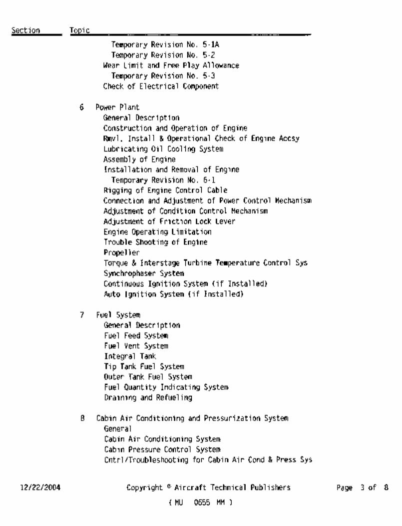
6 Power Plant
General DescriptionConstruction and Operation of EngineRmvl, Install Operational Check of Engine Accsy
Lubricating Oil Cooling System
Assembly of EngineInstallation and Removal of Engine
Temporary Revision No. 6-1
Rigging of Engine Control Cable
Connection and Adjustment of Power Control Mechanism
Adjustment of Condition Control Mechanism
Adjustment of Friction Lock Lever
Engine Operating Limitation
Trouble Shooting of Engine
PropellerTorque Interstage Turbine Temperature Control Sys
Synchrophaser SystemContinuous Ignition System (if Installed)
Auto Ignition System (if Installed)
7 Fuel SystemGeneral DescriptionFuel Feed SystemFuel Vent Syst’emIntegral Tank
Tip Tank Fuel SystemOuter Tank Fuel SystemFuel Quantity Indicating System
Draining and Refueling
8 Cabin Air Conditioning and Pressurization SystemGeneral
Cabin Air Conditioning SystemCabin Pressure Control SystemCntrl /Troubleshooting for ~Cabin Air Cond ´•Press Sys
12/22/2004 Copyright Aircraft Technical Publishers Page 3 of 8
MU 0655 MM)

Section ToDic
Air Supply System
Temporary Revision No. 8-1
9 Anti-Atmospheric SystemsGeneral
Surface De-Icing SystemWindshield Anti-Icing System
WiperDefogging System
Engine Air Intake Anti-Icing System
Propeller De-Icing SystemPitot and Static Anti-Icing SystemStall Warning Anti-Icing SystemOil Cooler Air Inlet Anti-Ice System
10 Instruments
General
Vacuum SystemPitot and Static Pressure System
Flight Instruments
Fuel Quantity Indicator
Engine Instruments
Other Instruments
11 Cabi n Equi pmentGeneral
Pilot and Go-Pilot Seat
Individual Reclining Seats
Refreshment Centers
12 Safety EquipmentGeneral
Oxygen SystemPortable Fire ExtinguisherFirst Aid Kit
Emergency Locator Transmitter (ELT) (if Installed)
13 Electrical SystemGeneral
DC Power Supply SystemAC Power Supply System
12/22/2004 Copyright Aircraft Technical Publishers .Page 4 of 8
MU 0655 ´•MM)

Section Topic
Lighting
Warning Systems
14 SupplementsSup 1 Trim-in-Motion Alert System
General
System DescriptionMaintenance
Functional Check
Troubleshooting
Wiring Diagram
Sup 2 Automatic Autopilot Disconnect SystemGeneral
System DescriptionMaintenance
Functional Check
TroubleshootingWiring Diagram
Sup 3 Pneumatic De-Ice Monitoring SystemGeneral
System DescriptionMaintenance
Functional Check
TroubleshootingWiring Diagram
Wiring Diagram Manual
List of Chapters (Table of Contents)
Manufacturer’s Introduction
Record of Revisions
Record of Temporary Revisions
List of Effective Pages
Alphabetical Index
21 Air ConditioningAir Conditioning Control (21-00-00)
Defog Overtemp (S/N 661SA) (21-00-10)
Defog Overtemp (S/N 697SA-730SA) (21-00-10)
24 Electrical Power
AC´•Power Source (S/N 661SA.697SA-710SA) (24-20-00)
12/22/2004 Copyright "Aircraft Technical Publishers Page 5 of 8
(´•MU 0655 ~MM)

Section Topic
AC Power Source (S/N 711SA-722SA) (24-20-00)
AC Power Source (S/N 723SA-730SA) (24-20-00)
DC Power Source (S/N 661SA) (24-30-00)
DC Power Source (S/N 697SA-713SA) (24-30-00)
DC Power Source (S/N 714SA-730SA) (24-30-00)
Battery Overtemp Warning (S/N 661SA) (24-30-10)
Battery Overtemp Warning (697SA-730SA) (24-30-10)
Cockpit Relay Box (S/N 661SA) (24-50-10)
Cockpit Relay Box (S/N 697SA-717SA) (24-50-10)
Cockpit Relay Box (S/N 718SA-730SA) (24-50-10)
Overhead Switch Console (24-50-20)
Overhead Auxiliary Switch Panel (24-50-30)
26 Fire Protection
Eng Fire Detctng Circ (661SA,697SA-713SA) (26-10-00)
Eng Fire Detecting Circuit (714SA-730SA) (26-10-00)
27 Flight Controls
Control Column (27-00-00)
Trim Aileron Control (661SA.697SA-713SA) (27-10-00)
Trim AileronControl (714SA-730SA) (27-10-00)
Trim Aileron Position Indication (27-10-10)
Stall Warning System (27-30-10)
Flap Control (661SA) (27-50-00)
Flap Control (697SA-700SA) (27-50-00)
Flap Control (701SA-713SA) (27-50-00)
Flap Control (714SA-730SA) (27-50-00)
28 Fuel
Main Tank Fuel Control (28-20-00)
Fuel Transfer Cntrl (661SA,697SA-713SA) (28-20-10)
Fuel Transfer Control (714SA-730SA) (28-20-10)
Fuel Quantity Ind (661SA,697SA-713SA) (28-40-00)
Fuel Quantity Ind (714SA-730SA) (28-40-00)
Fuel FilterBypass/Boost Pump Failure (28-40-10)
30 Ice and Rain Protection
Wing ´•De-Ice (30-10-00)
Engine Air InletAnti-Ice (30-20-00)
Oil Clr Init Anti-Ice (661SA,697SA-713SA) (30-20-10)
Oil Cooler Inlet Anti-Ice (714SA-730SA) (30-20-10)
12/22/2004 :Copyright Aircraft Technical Publishers Page 6 of 8
MU 0655 MM)
Section Topic
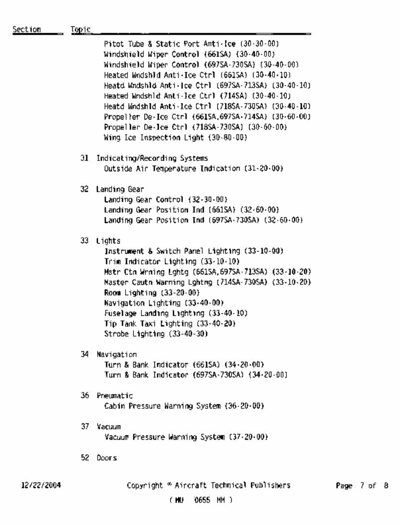
Pitot Tube Static Port Anti-Ice (30-30-00)
Windshield Wiper Control (661SA) (30-40-00)
Windshield Wiper Control (697SA-730SA) (30-40-00)
:Heated Wndshld Anti-Ice Ctrl (661SA) (30-40-10)
Heatd Wndshld Anti-Ice Ctrl (697SA-713SA) (30-40-10)
Heated Wndshld Anti-Ice Ctrl (714SA) (30-40-10)
Heatd Wndshld Anti-Ice Ctrl (718SA-730SA) (30-40-10)
Propeller De-Ice Ctrl (661SA,697SA-714SA) (30-60-00)
Propeller De-Ice Ctrl (718SA-730SA) (30-60-00)
Wing Ice Inspection Light (30-80-00)
31 Indicating/Recording SystemsOutside Air Temperature Indication (31-20-00)
32 Landing Gear
Landing Gear Control (32-30-00)
Landing Gear Position Ind (661SA) (32-60-00)
Landing Gear Position Ind (697SA-730SA) (32-60-00)
33 LightsInstrument Switch Panel Lighting (33-10-00)
Trim Indicator Lighting (33-10-10)
:Mstr Ctn Wrning Lghtg (661SA,697SA-713SA) (33-10-20)
Master Cautn Warning Lghtng (714SA-730SA) (33-10-20)
Room Lighting (33-20-00)
Navigation Lighting (33-40-00)
Fuselage Landing Lighting (33-40-10)
Tip Tank Taxi Lighting (33-40-20)
Strobe Lighting (33-40-30)
34 NavigationTurn Bank Indicator (661SA) (34-20-00)
Turn Bank Indicator (697SA-730SA) (34-20-00)
36 Pneumatic
Cabin Pressure Warning System (36-20-00)
37 Vacuum
Vacuum Pressure Warning System (37-20-´•00)
52 Doors
12/22/2004 Copyright Aircraft Technical Publishers Page 7 of 8
(’MU ’0655 MM3

Section Topic
Door Seal (52-10-00)
Door Lock Warning (52-70-00)
61 ´•P rope 1 1 ers lPropul sors
Propeller Synchrophaser Control (61-20-00)
73 Engine Fuel and Control
Fuel Pressure Indication (661SA) (73-30-10)
Fuel Pressure Indication (697SA-713SA) (73-30-10)Fuel Pressure Indication (714SA-730SA) (73-30-10)
76 Engine Controls
Engine Propeller Control (76-00-003
77 Engine IndicatingEngine Instrument Indication (77-00-00)
End of Index
12/22/2004 Copyright Aircraft Technical ;Publishers ’Page 8 of 8
MU 0655 ´•MM)

NI FGI
INTRO

i
nn
nn LI~I N T E N PL N C E
nn A, N uA.LDOCUMENT NUMBER MR-0218
ORIGINAL ISSUE 1DECEMBER~977
REVISION DATE: 27 DE C: EMBER ?999
EJIHEAVY IW DUSTRIES,
APPLICABLE TO AIRPLANE SERIAL NUMBERS
652, 661, 697 THROUGH 699 AND 701 THROUGH
730.

RECORD OF REVISIONS
MFG REV
NO DESCRIPTION ISSUEDATE ATPREVDATE INSERTEDBY
12/27/99 ISee List of Effective Pages 12/27/99 11/13/00 ATP/IB
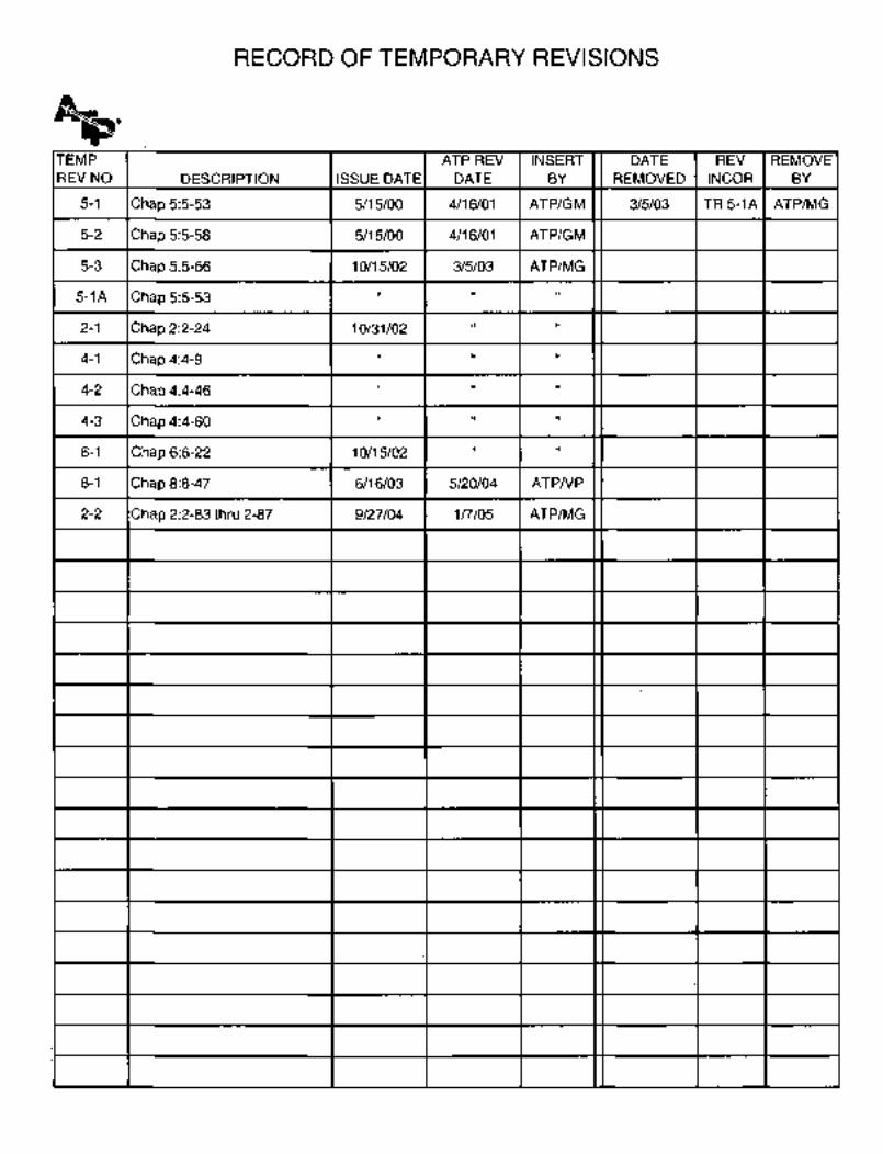
:RECORD OF TEMPORARY REVISIONS
TEMP ATP REV INSERT DATE REV REMOVE
REV NO DESCRIPTION ISSUE DATE DATE BY REMOVED INCOR BY
5-1 Chap 5:5-53 5/15/00 4/16/01 ATP/GM 3/5/03 TR5-IA ATP/MG
5-2 Chap 5:5-58 5/15/00 4/16/01 ATP/GM
5-3 Chap 5:5-66 10/15/02 3/5/03 ATP/MG
5-1A Chap 5:5-53
2-1 Chap 2:2-24 10/31/02
4-1 Chap 4:4-9
4-2 Chap 4:4-46
4-3 Chap 4:4-60
6-1 Chap 6:6-22 10/15/02
8-1 Chap 8:8-47 6/16/03 5/20/04 ATPNP
2-2 Chap 2:2-83 thru 2-87 9/27/04 1r//05 ATP/MG
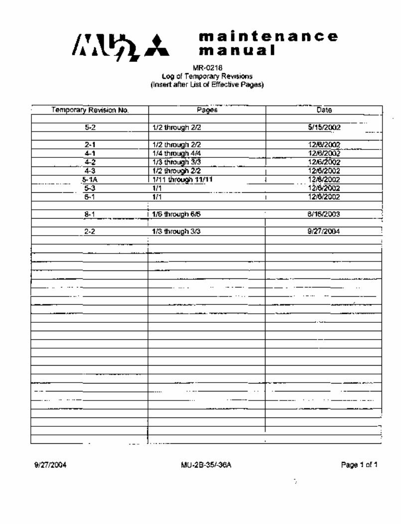
c~it3maintenanceman ual
MR-0218
Log of Temporary Revisions
(Insert after List of Effective Pages)
T Revision No. P Date
5-2 1/2 th 2/2 5/15/2002
2-1 1/2 2/2 12/6/2002
4-1 1/4th 4/4 12/6/2(302
4-2 1/3 t~irough 3/3 12/6/2002
4-3 1/2 2/2 12/6/2002
5-1A 1/11 11/11 12/6/2002
5-3 1/1 12/6/2002
6-1 1/1 12/6/2002
8-1 1/6 h 6/6 6/16/2003
2-2 1/3 3/3 9/27/2004
9/27/2004 MU-2B-35/-36A Page 1 of 1

M3iT$UBTSSE~I
VlirTSUBLSHI SEP(VICE PUBLICATIOWS TR4NSMITT;aL
The undemoted Mitsubishi MU-2B series Service Publication has baen issued by Mitsubishi HeavyIndus~-triea, Ltd, in 3apan.It is thp, ownai´• a~d/or responsibiliS to sdhere to or comply with
new infonnation contained in the undemdtec2 pubricafion attached hereto,
aa~e Pub Descri-ction tv mitials
IZ/1M I
Pf~EG 13 DtSPRIBUS"EIS B~ fUWBIPIE
6E6PVIQE~, IM~., ADD~SBM, IIWDER CBRhTRPb@P
EI~W IPIL)LfSfRli3B ARA.E3RICA IN~G., LbPEDE~ FRO~INDUSTIRBES LTf6. P4DDfP‘eSS AtD @QIWMEMT8~B
INeBLlr[l;glES PgEOARIPBMG DfSTRIK3UPfBPd O´•F f#IS PUBtlCAT)BN O´•W
~PE@EI$P QP A~6\P TH´•E IDUBh;56A~IONS LkSTE~E) #ERIM T~6:
Turbi.ne PkircrafS Services me,
4550 Simmg Dodlitf~le Drive,
lb,ddison, Te~as 75001
USA
AKentio´•n: Ridk Wheldon
Tel: (972) 248-3108 X209
Fa~: C~72) 248-3321
4951 ALRPORT PARKWAY,SUITEBOO 93C5480
ADDISON, TEXkS 75001 FACSIMILE: (972) 93~-5488

’i
MITSUBISHI -HEAVY INDUS;rRIES AMERICA INC.
MITSUBISIII_SERVTCE PUBLICGTZONS
The undemoted Mitsubishi MU-2B series Service Publication has been issued by Mitsubishi
Heavy Industries, Ltd. in Japan. It is’the owner and/or operator’s responsibility to adhere to or
comply with new information contained in the undernoted publication attached hereto.
MR-0218 Temporary Revision 8-1
NOT~E
THIS PUBLICATION IS‘ PRINTED AND/OR DISTRIBUTED BY TURBINE
AlRCRAFT.’SERVICES, INC., ADPISON, TEXAS UN I)ER C;OWTRdCT WITH
M~TSUBISHI´•HEAVY INDUSTRIES AMERICA IN-C., UNDER LICENSE
FROM MITSUB1SHI HEAVY INDUSTRIES LTD; ADDRESS’ ALL
COMMENTS OR INQUIRIES REGARDING DIST~ijBUTION OF THIS
PUBLICATION OR RECEIPT OF ANY OF THE PUBLICATIONS LISTED
HEREIN TO:
Turbine Aircraft Senrices Inc.
4550 Jimmy Doolittle Drive,
Addison, Texas 75001
USA
Attention: Rick Wheldon
Tef: (972) 24813108 X209.
Fax: (972) 24813321
4951 AIRPORT PARKWAYISUITE 800 TELEPHONE: (972) 934´•5480
ADDISONI TEXAS 75001 FACSIMILE: (912) 934-5488
:m a i n t a n, a n cem~a n u I
LIST OF EFFECTIVE PAGES
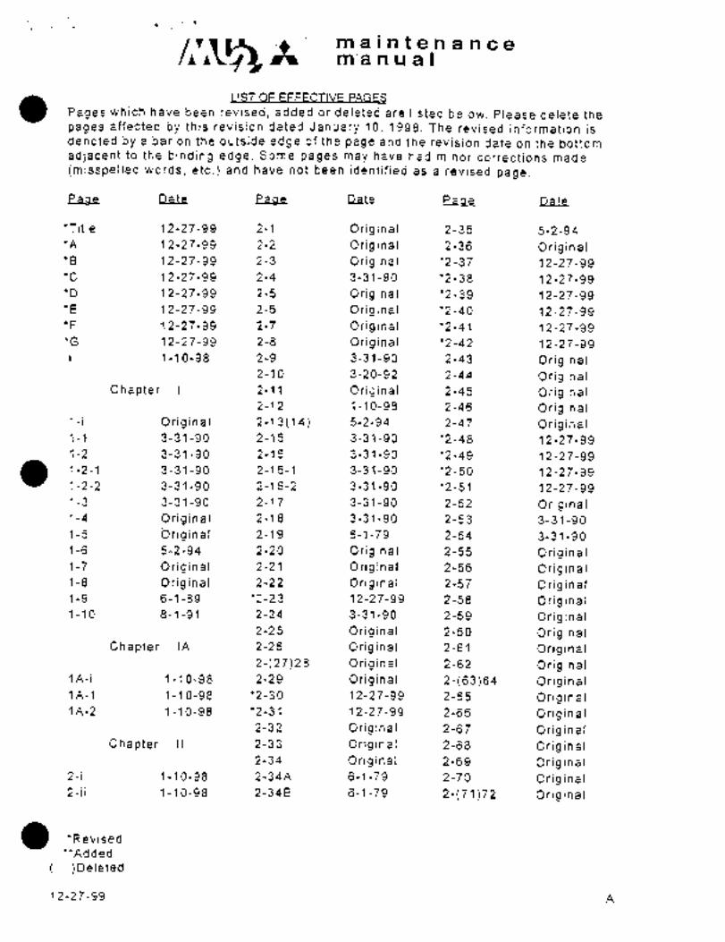
Pages which have been revised, added or deleted are listed below. Please delete the
pages affected by this revision dated January 10, 1998. The revised’information isdenoted by a bar on the outside edge of the page and the revision date on the bottom
adjacent to th-e binding edge. Some pages may have had minor corrections made
(misspelied words, etc.) and have not been identified as a ievised page.
Pace eaae Date Pace Date
*Title 12-27-99 2-1 Original 2-35 5-2-94
*A 12-27-99 2-2 Original 2-36 Original*B 12-27-99 2-3 Original *2-37 12-27-99
*C 12-27-99 2-4 3-31-90 ’2-38 12-27-99
*D 12-27-99 2-5 Original *2-39 12-27-99
*E 12-27-99 2-6 Original *2-40 12-27-99
*F 12-27-99 2-7 Original *2-41 12-27-99
*G 12-27-99 2-8 Original *2-42 12-27-99
1-10-98 2-9 3-31-90 2-43 Original2-10 3-20-92 2-44 Original
Chapter 1 2-11 Original 2-45 Original2-12 1-10-98 2-46 Original
1-i Original 2-13(14) 5-2-94 2-47 Original1-1 3-31-90 2-15 3-31-90 ’2-48 12-27-99
1-2 3-31-90 2-16 3-31-90 *2-49 12-27-99
1-2-1 3-31-90 2-16-1 3-31-90 *2-50 12-27-99
1-2-2 3-31-90 2-16-2 3-31-90 ’2-51 12-27-99
1-3 3-31-90 2r17 3-31-90 2-52 Original1-4 Original 2-18 3-31-90 2-53 3-31-90
1-5 briginal 2-19 6-1-79 2-54 3-31-90
1-6 5-2-94 2-20 Original 2-55 Original1-7 Original 2-21 Original 2-56 Original1-8 Original 2-22 Original 2-57 Original1-9 6-1-89 *2-23 12-27-99 2-58 Original1-10 8-1-91 2-24 3-3´•1-90 2-59 Original
2-25 Original 2-60 OriginalChapter IA 2-26 Original 2-61 Original
2-(27)28 Original 2-62 Original1A-i 1-10-~8 2-29 Original 2-(63)64 Original1A-l 1-10-98 ’2-30 12-27-99 2-65 Original1A-2 1-10-98 ’2-31 12-27-99 2-66 Original
2-32 Original 2-67 OriginalChapter 11 2-33 Original 2-68 Original
2-34 Original 2-69 Original2-i 1-10-98 2-34A 6-1-79 2-70 Original2-ii 1-10-98 2-34B ’6-1-79 2-~71)72 Original
*Rev´•ised
**Added
)Deleted
12-27-99 A
maintenancemanual
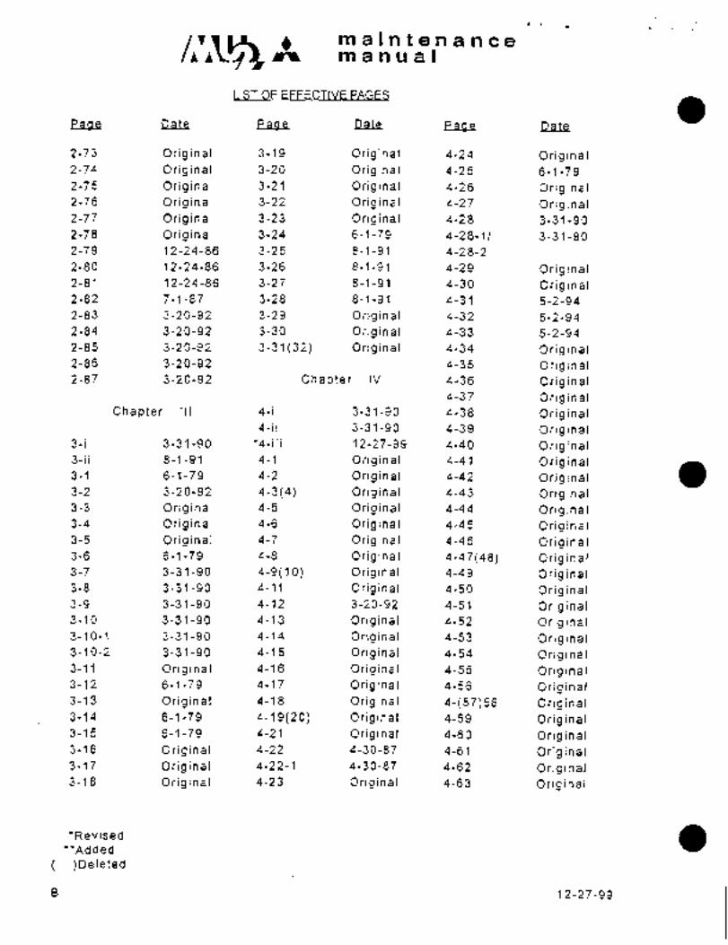
LIST OF EFFECTIVE PAGES
Pane Page Page Date
2-73 Original 3-19 Original 4-24 Original2-74 Original 3-20 Original 4-25 6-1-79
2-75 Original 3-21 Original 4-26 Original2-76 Original 3-2? Original 4-27 Original2-77 Original 3-23 Original 4-28 3-31-90
2-78 Original 3-24 6-1-79 4-28-1/ 3-31-90
2-79 12-24-86 3-25 8-1-91 4-28-2
2-80 12-24-86 3-26 8-1-91 4-29 Original2-81 12-24-86 3-27 8-1-91 4-30 Original2-82 7-1-87 3-28 8-1-91 4-31 5-2-94
2-83 3-20-92 3-29 Original 4-32 5-2-94
2-84 3-20-92 3-30 Original 4-33 5-2-94
2-85 3-20-92 3-31(32) Original 4-34 ~Original2-86 3-20-92 4-35 Original2-87 3-20-92 Chapter IV 4-36 Original
4-37 OriginalChapter III 4-i 3-31-90 4-38 Original
4-ii 3-31-90 4-39 Original3-i 3-31-90 *4-iii 12-27-99 4-40 Original3-ii 8-1-91 4-1 Original 4-41 Original3-1 6-1-79 4-2 Original 4-42 Original3-2 3-20-92 4-3(4) Original 4-43 Original3-3 Original 4-5 Original 4-44 Original3-4 Original 4-6 Original 4-45 Original3-5 Original 4-7 Original 4-46 Original3-6 6-1-79 4-8 Original 4-47(48) Original3-7 3-31-90 4-9(10) Original 4-49 Original3-8 3-31-90 4-11 Original 4-50 Original3-9 3-31-90 4-12 3-20-92 4-51 Original3-10 3-31-90 4-13 Original 4-52 Original3-10-1 3-31-90 4-14 Original 4-53 Original3-10-2 3-31-90 4-15 Original 4-54 Original3-11 Original 4-16 Original 4-55 Original3-12 6-1-79 4-17 Original 4-56 Original3-13 Original 4-18 Original 4-(57)58 Original3-14 6-1-79´• 4-19(20) Original 4-59 Original3-15 6-1-79 4-21 Original 4-60 Original3-16 Original 4-22 4-30-87 4-61 Original3-17 Original 4-22-1 4-30-87 4-62 Original3-18 Original 4-23 Original. 4-63 Original
’Revised
*’Added
)Deleted
B 12-27-99

C~153 TTi a i n t a n a n cemanu;ral
LIST OF EFFECTIVE PAGES
Pane Page Date Pa9e Date
4-64 Original 4-101 6-1-79 5-16 Original4-65 Original 4-102 6-1-79 5-17 Original4-66 Original 4-(102A)1028 6-1-79 5-18 Original4-67 Original 4-103 6-1-79 5-19 Original4-68 Original 4-104 6-1-79 5-20 Original4-69 Original 4-(104A)104B 6-1-79 5-21 Original4-70 Original 4-105 6-1-79 5-22 Original4-71 Original 4-106 6-1-79 5-23 Original4-72 Original 4-(106A)106B 6-1-79 5-24 Original4-73 Original 4-107 6-1-79 5-25 Original4-74 Original 4-108 6-1-79 5-26 Original4-75 Original 4-(108 A)108B 6-1-79 5-27 Original4-76 6-1-79 4-109 6-1-79 5-28 3r31-90
4-77 Original 4-110 6-1-79 5-29 3-31-904-78 Original 4-(110A)110B 6-1-79 5-30 Original4-79 Original 4-111(112) 6-1-79 5-31 5-2-94
4-80 Original 4-113 Original 5-32 Original4-81 Original 4-114 Original 5-33 Original4-82 Original *4-115 12-27-99 5-34 3-31-90
4-83 Original ""4-116 12-27-99 5-35 Original4-84 Original 5-36 3-31-90
4-85 4-1-78. Chapter V 5-37 Original4-86 Original 5-38 Original4-87 Original *5-i 12-27-99 5-39 Original4-88 Original *5-ii 12-27-99 5-40 Original4-89 Original 5-1 Original 5-41 Original4-90 Original 5-2 Original 5-42 Original4-91 Original 5-3 Original 5-43 Original4-92 Original 5-4 Original 5-44 Original4-(93)94 6-1-79 5-5 Original 5-45 Original4-(94A)948 6-1-79 5-6 Original 5-46 Original4-95 6-1-79 5-7 Original 5-47 Original4-96 6-1-79 5-8 Original 5-48 Original4-~96A)968 6-1-79 5-9 Original 5-49 Original4-97 6-1-79 5-10 Original 5-50 Original4-98 6-1-79 5-11 Original 5-51 Original4-(98A)988 6-1-79 5-12 Original 5-52 Original4-99 6-1-79 5-13 Original 5-53 Original4-100 6-1-79 5-14 Original 5-54 Original4-(100A)1O0B 6-1-79 5-15 Original 5-55 Original
*Revised
"Added
)Deleted
12-27-99 C

maintenancemanual
ISTOF EFFECTIVE PAGES
eaae Date eae Date Paae Date
5-56 Original 6-19 5-2-94 6-62-11 3-31-90
5-57 Original 6-20 Original 6-62-2
5-58 Original 6-21 Original 6-63 Original5-59 5-2-94 6-22 Original 6-64 Original5-60 5-2-94 6-23 Original 6-65 -Original5-60-11 5-2-94 6-24 Original 6-66 Original5-60-2 6-25 Original 6-67 Original5-61 Original 6-26 Original 6-68 Original5-62 Original 6-27 Original 6-69 Original5-63 Original 6-28 6-1-79 6-70 9-15-80
5-64 Original 6-29 5-2-94 6-71 9-.15-80
5-65 Original 6-30 5-2-94 6-72 9-15-80
5-66 Original 6-31 Origina´•l 6-73 3-31-90
*5-67 12-27-99 6-32 Original 6-74 1-10-98
’5-68 12-27-99 6-33 3-31-90 6-75 3-31-90
"5-69 12-27-99 6-34 3-31-90 6-76 1-10-98
6-35(36) OriginalChapter VI 6-37 3-31-90 Chapter VII
6-37-1 3-31-90
6-i 3-31-90 6-37-2 3-31-90 7-i 3-31-90
6-ii 3-31-90 6-38 9-15-80 7-ii 3-31-90
6-iii 1-10-98 6-39 Original 7-1 Original6-1 3-31-90 6-40 Original 7-2 3-31-90
6-2 Original 6-41(42) 6-1-79 7-2-1/ 3-31-90
6-3 Original 6-43 Original 7-2-2
6-4 6-1-79 6-44 Original 7-3 Original6-5 6-1-79 6-45(46-50) Original 7-4 Original6-6 Original 6-51 Original 7-5 Original6-7 Original 6-52 Original 7-6 Original6-8 Original 6-53 Original 7-(7)8 Original6-9(10) Original 6-54 Original 7-9 Original6-11 Original 6-55 Original 7-10 Original6-12 3-31-90 8-56 9-15-80 7-11 Original6-12-1/ 3-31-90 6-57 Original 7-12 Original6-12-2 6-58 Original 7-13 Original6-13 Original 6-59 Original 7-14 Original6-14 Original 6-60 Original 7-15 Original6-15(16) Original 6-61 3-31-90 7-16 Original6-17 5-2-94 6-62 3-31-90 7-17 Original6-18 5 -2.-94 7-18 Original
*Revised
**Added
)Deleted
D 12-27-99

maintenancemanual
LIST OCEFFECTIVE PAGES
Page rSate Page eaae Date
7-19 Original 8-5 Original 8-43~ Original7-20 Original 8-6 Original 8-44 Original7-21 O’riginal 8-7 Original 8-45 Original7-22 Original 8-8 Original 8-46 Original7-23 Original 8-9´• Original 8-47 4-1-78
7-24 Original 8-10 Original 8-48 4-1-787-25 Original 8-11 Original7-26 Original 8-12 Original Chapter IX7-27 Original 8-13 Original7-28 Original 8-14 Original 9-i 3-31-90
7-(29)30 Original 8-15 Original 9-ii 3-31-90
7-31 Original 8-16 Original 9-1 Original7-32 Original 8-17 Original 9-2 Original7-33 Original 8-18 Original 9-3 Original7-34 Original 8-19 Original 9-4 Original7-35 Original 8-20 Original 9-5 Original7-36 Original 8-21 Original 9-6 Original7-37 Original 8-22 Original 9-7 Original7-37-1 3-31-90 8-23 Original 9-8 3-31-90
7-37-2 3-31-90- 8-24 Original 9-8-1/ 3-31-90
7-37-3 3-31-90 8-25 Original 9-8-2
7-37-4 3-31-90 8-26 Original 9-9 Original7-37-51 3-31-90 8-27 3-31-90 9-10 Original7-37-6 8-28 3-31-90 9-11 6-1-79
7-38 Original 8-28-1/ 3-31-90 9-12 6-1-79
7-39 4-1-78 8-28-2 9-13 Original7-40 Original 8-29 Original 9-14 Original7-41 Original 8-30 Original 9-15 Original7-42 Original 8-31 Original 9-16 Original7-43 3-31-90 8-32 Original 9-17 Original7-44 3-31-90 8-33 Original 9-18 Original
8-34 Original 9-19 OriginalChapter VIII 8-35 Original 9-20 Original
8-36 Original 9-21 Original8-i 3-31-90 8-37 Original 9-22 6-1-798-ii 3-31-90 8-38 Original 9-22A(B) 6-1-79
8-1 3-31-90 8-39 Original 9-23 Original8-2 Original 8-40 Original 9-24 Original8-3 Original 8-41 Original 9-25 Original8-4 Original 8-42 Original 9-26 Original
*Revised
’*Added
)Deleted
12-27-99 E
maintenancemanual
~IST OF EFFECTIVE PAGES
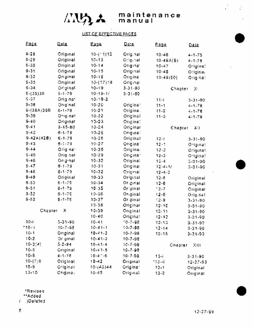
Page Date Paaa Date Page Date
9-28 Original 10-(11)12 Original 10-46 4-1-78
9-29 Original 10-13 Original 1o-46A(B) 4-1-78
9-30 Original 10-14 Original 10-47 Original9-31 Original 10-15 Original 10-48 Original9-32 Original 10-16 Original 10-49(50) Original9-33 Original 10-(17)18 Original9-34 Original 10-19 3-31-90 Chapter XI
9-(35)36 6-1-79 10-19-1/ 3-31-90
9-37 Original 10-19-2 11-i 3-31-90
9-38 Original 10-20 Original 11-1 4-1-78
9-(38A)388 6-1-79 10-21 Original 11-2 4-1-78
9-39 Original 10-22 Original 11-3 4-1-78
9-40 Original 10-23 Original9-41 9-15-80 10-24 Original Chapter XII
9-42 6-1-79 10-25 Original9-42A(428) 6-1-79 10-26 Original 12-i 3-31-90
9-43 6-1-79 10-27 Original 12-1 Original9-44 Original ´•10-28 Original 12-2 Original9-45 Original 10-29 Original 12-3 Original9-46 Original 10-30 Original 12-4 3-31-90
9-47 6-1-79 10-31 Original~ 12-4-11 3-31-90
9-48 6-1-79 10-32 Original 12-4-2
9-49 Original 10-33 Original 12-5 O r.i g i n a I
9-50 6-1-79 10-34 Original 12-6 Original9-51 6-1-79 10-35 Original 12-7 Original9-52 6-1-79 10-36 Original 12-8 Original9-53 6-1-79 10-37 Original 12-9 3-31-90
10-38 Original 12-10 3-31-90
Chapter X 10-39 Original 12-11 3-31-90
10-40 Original 12-12 3-31-90
10-i 3-31-90 10-41 10-7-98 12-13 3-31-90
*10-ii 10-7-98 10-41-1 10-7-98 12-14 3-31-90
10-1 Original 10-41-2 10-7-98 12-15 3-31-90
10-2 Original 10-41-3 10-7-98
10-3(4) 5-2-94 10-41-4 10-7-98 Chapter XIII
10~5 Original 10-41-5 10-7-98
10-6 4-1-78 10-41-6 10-7-98 13-i 3-31-90
10-(7)8 Original 10-42 Original *13-ii 12-27-99
10-9 Original 10-(43)44 Original 13-1 Original10-10 Original 10-45 Original 13-2 Original
*Revised
"Added
)Deleted
F 12-27-99

A maintenancemanual
LIST OF EFFECTIVE PAGES
qa~ Paoe Date P a_a e Date
13-3 Original 13-44 Original 13-85 6-1-79
13-4 Original 13-45 Original 13-86 Original13-5 Original 13-46 Original 13-87 Original13-6 Original 13-47 Original 13-88 Original13-7 3-31-90 13-48 Original 13-89 Original13-8 Original 13-49 Original ’13-90 Original13-(9)10 4-1-78 13-50 Original 13-91 Original13-11 Original 13-51 Original **13-92 12-27-99
13-12 4-1-78 13-52 Original ’"13-93 12-27-99
13-13 Original 13-53 Original "’13-94 12-27-99
13-14 Original 13-54 Original ""13-95 12-27-99
13-15 Original 13-55 Original "’13-96 12-27-99
13-16 Original 13-56 4-1-78
13-17 Original 13-57 Original Supplement13-18 Original 13-58 Original13-19 Original 13-59 Original Sup.l-i 1-10-98
13-20 4-1-78 13-60 Original Sup.l-l 1-10-98
13-21 4-1-78 13-61 3-31-90 Sup.l-2 1-10-98
13-22 Original 13-62 Original Sup.l-3/1-4 1-10-98
13-23(24) Original 13-63 Original Sup.2-i 1-10-98
13-25 Original 13-64 Original Sup.2-l 1-10-98
13-26 Original 13-65 Original Sup.2-2 1-10-98
13-27 Original 13-66 1-10-98 Sup.2-3/2-4 1-10-98
13-28 6-1-79 13-67 Original Sup.2-5/2-6 1-10-98
13-29 Original 13-68 Original Sup.3-i 1-10-98
13-30 Original 13-69 Original Sup.3-l 1-10-98
13-31 3-31-90 13-70 Original Sup.3-2 1-10-‘9813-32 Original 13-71 Original Sup.3-3/3-4 1-10-98
13-33 Original 13-72 Original13-34 6-1-79 13-73 Original13-35 Original 13-74 4-1-78
13-36 3-31-90 13-75 4-1-78
13-36-1/ 3-31-90 13-76 4-1-78
13-36-2 13-77 Original13-37 Original 13-78 ´•Original13-38 Original 13-79(80) Original13-39 Original 13-81 4-1-78
13-40 Original 13-82 4-1-78
13-41(42) Original 13-83 Original13-43 Original 13-84 4-1-78
*Revised
**Added
)Deleted
12-27-99 G
maintenancemanual
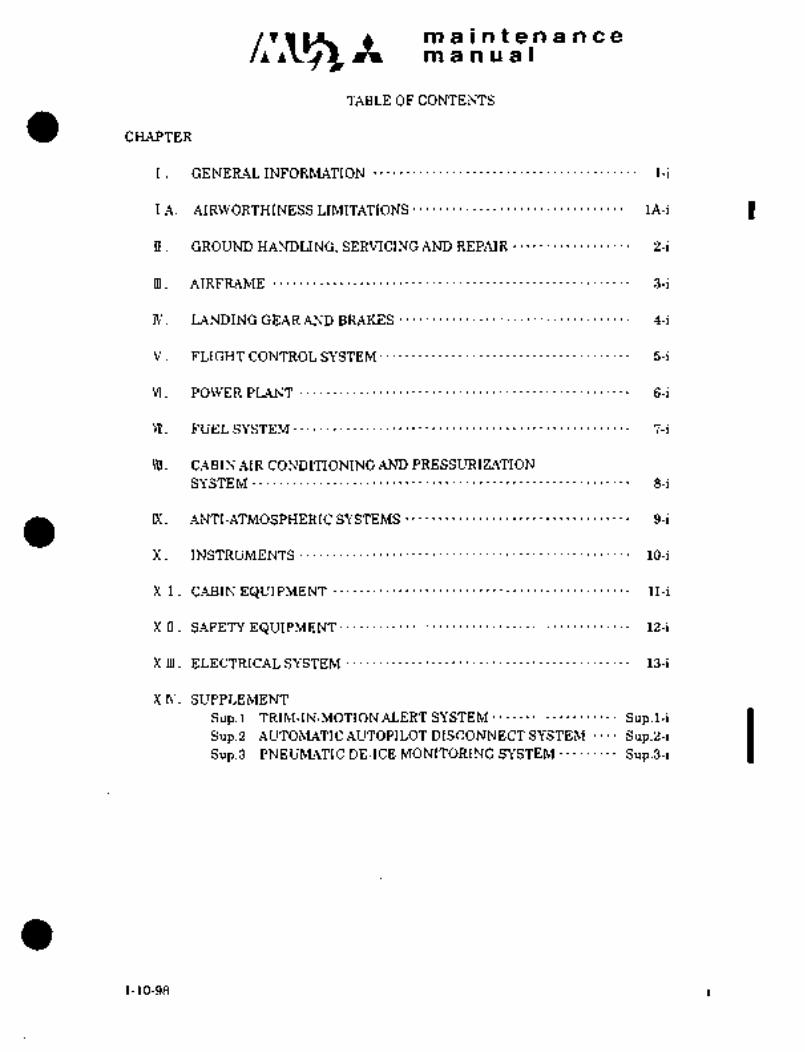
TABLE OF CONTENTS
CHAPTER
I. GENERALINFORMATION 1-i
IA. AIRWORTHINESS LIMITATIONS 1A-i I
IT. GROUND HANDLING, SERVICING AND REPAIR 2-i
m. AIRFRAME 3-i
LANDING GEAR AND BRAKES 4-i
V. FLIGHT CONTROL SYSTEM´• 5-i
VI. POWER PLANT 6-i
W. FUEL SYSTEM 7-i
WI. CABIN AIR CONDITIONING AND PRESSURIZATION
SYSTEM 8-i
IX. ANTI-ATMOSPHERIC SYSTEMS 9-i
X. INSTRUMENTS 10-i
X I CABIN EQUIPMENT 11-i
X II. SAFETY EQUIPMENT 12-i
X m. ELECTRICAL SYSTEM 13-i
XIV. SUPPLEMENT
Sup.l TRIM-IN-MOTIONALERT SYSTEM Sup.l-i
Sup.B AUTOMATICAUTOPILOT DISCONNECTSYSTEM Sup.2-iSup.3 PNEUMATIC DE-ICE MONITORING SYSTEM Sup.3-i
1-10-98 i

CHAPTER
GENERAL
INFORNIATION

c~ m alnQe 91 an c a
manual
CHAPTER I
GENERAL INFORMATION
CONTENTS
i. GENERAL 1-1
2. STATION DIAGRAM 1-4
2.1 GENERAL DESCRIPTION 1-4
3. GE~TERAL SPECIFICATIONS 1-6
3.1 ENGINE 1-6
3.2 PROPELLER 1-6
3.3 AIRFRAME 1-7
3.4 WEIGHT 1-9

c~-’Cr Itmaintenanceman ual
i. GENERAL
The MU-2 is a high wing, multi-engine turboprop type aircraft powered bytwo Garrett TPE 331-6-251# 715 SHP (*1), or TPE 331-5-252M 715 SHP ("2).The fuselage is of semi-monocoque construction with additional rigiditygained through the use of two lower parallel keels.
The aircraft is standard with an 8 place seating configuration and an 11
place high density seating arrangement is available.
The main wing center section LH W STA 2590 through ph W STA 2590 is of
integral tank design (154 U.S. gallons) utilizing a built up front and
rear spar, ribs, stringers, and stressed, chem-milled skin containingtank access doors. The outboard wings are of the same basic construction
utilizing lighter skins and stringers. ~Each outboard wing contains a
removable aluminum fuel tank of 15 U.S. gallon capacity. The outboard
wing is attached to the inboard section by four bolts through hard pointsat the upper and lower spar caps. The main wing is attached to the
fuselage by four bolts through clevis type wing to fuselage attach fittings.
The tip tanks (90 U.S. gallons each) are attached to the forward and
rear spar by three bolts; fuel from these tanks is transferred byregulated air pressure.
Lateral control is accomplished through a spoiler system. Enabling the
use of full span, doubled slotted flaps are actuated by a single DC motor
through a reduction gearbox and drive shafts.
The tricycle type landing gear is retracted by a single DC motor througha reduction gear drive train. The main gear retracts forward into the
fuselage bulge, while the nose gear retracts forward into the nose gearwheel bay.´• Emergency gear extension is accomplished through a manual
ratchet system. Nose gear steering is manually linked to the rudder pedals.
All flight controls are manual systems except lateral trim which is
through electrical actuators installed in the trailing edge of the flaps.The MU-2 hydraulic system consists of two disc type brakes, two mixer
valves and four master cylinders. The pressurization system for the cabin
compartment is provided by engine compressor bleed air which is circulated
across a two stage cooling turbine to provide conditioned air. The systemis capable of 5 psi (*1), 6 psi (*2) differential pressure and will providea cabin altitude of 6,500 feet ("1), 9,000 feet (*2) at a flight altitude
of 25,000.
~I Aircraft S/N 652SA
~2 Aircraft S/N 661SA, 697SA and subsequent
3-31-90

c~rmaintenancemanual
IWARNING)
Use only genuine MITSUBISHI or MITSUBISHI approved partsobtained from MITSUBISHI approved sources and Beech partssupport network, in connection with the maintenance and
repair of MITSUBISHI airplanes.Genuine MITSUBISHI parts are produced and inspected under
rigorous procedures to ensure airworthiness and suitabilityfor use in MITSUBISHI airplane applications. Parts purchasedfrom sources other than MITSUBISHI and Beech parts supportnetwork, even though outwardly identical in appearance maynot have had the required tests and inspections performed,may be different in fabrication techniques and materials,and may be dangerous when installed in an airplane. Salvagedairplane parts, reworked parts obtained from non-MITSUBISHI/Beech approved sources, or parts, components, or structural
assemblies, the service history of which is unknown or cannot
be authenticated, may have been subjected to unacceptablestresses or temperatures or have other hidden damage, not
discernible through routine visual or usual nondestructive
testing techniques.This may render the parts, components or structural assembly,even though originally manufactured by MITSUBISHI, unsuitableand unsafe for airplane use. MITSUBISHI expressly´•disclaimsany responsibility for malfunctions, fai lures, damage or
injllrv caused by use of non-MITSUBISHI /Beech approved parts.Contact Beech Aircraft Corporation for MITSUBISHI approvedparts support network.
1-2 3-31-90

maintenancemanual
This page is intentionally blank.
3-31-90 1-2-1
CI
1\3
h) I B
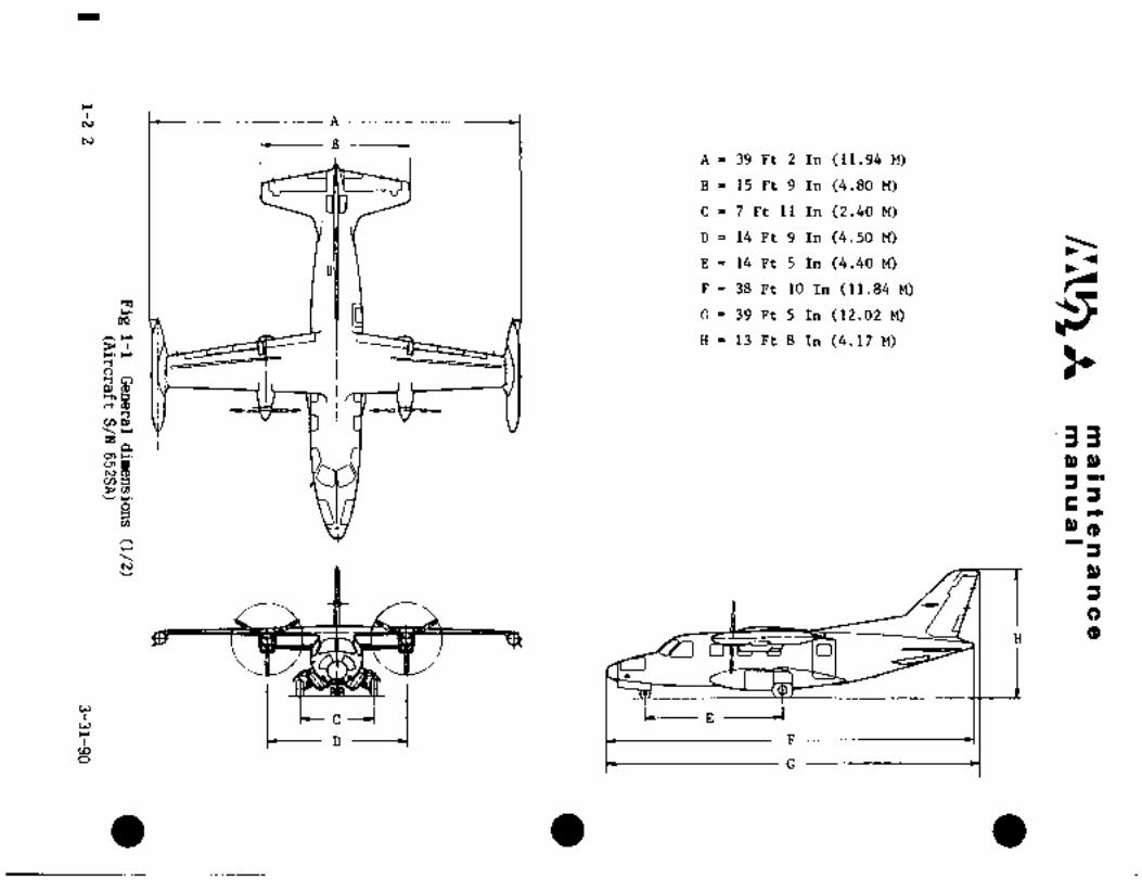
A 39 Ft 2 In (11.94 M)
B 15 Ft 9 In (4.80 M)
C 7 Ft 11 In (2.40 M)
D 14 Ft 9 In (4.50 M)
E 14 Ft 5 In (4.40 M)
F 38 Ft 10 In (11.84 M)~1
0 39 Ft 5 In (12.02 M)oSZ;’H 13 Ft 8 In (4.17 M)
r. r
ctm
v,p,
z ´•33a
p, P,N
r+m Pl(pr
I P)
C)
H (PO
L _Io
cwr
a L G

Aw
c3r
0
II II II II II II II II
utocs~PIP vlror
rr~rrcrrrct´•rcrt~cre rcct~
r 4
E;5 c~c(w0
E~33~P C´•´•
~´•09 hC~ C~
~J IPCIOr N
rpr ii O to
0000~h P~ao IP
~bggp(_zn,
´•1cnP,o~r
a 33I p)p,
tom I) (1 I I´•
-J r´•
v,
Ba n) ~p
P)
f C)~t (P’H
CI
II
ci
I
FU6002
wD G

m a Int a a a n.e a
manual
2. STATION DIAGRAM (See Fig. 1-2)
2. 1 GENERAL DESCRIPTION
(1) Fuselage
Fuselage station (F. STA) is a plane perpendicular to the center line of
fuselage circular section. Station 0 is located 170 mm (6.693 in.) aft
of the fuselage nose.
Buttock plane (B. P. is a plane parallel to fuselage center plane, (B. P. O).Water plane (W. P. is a plane parallel to fuselage horizontal center plane.
NOTE
Station locations are given in metric measurement
(millimeters). To convert station locations to inches
divide the number given by 25. 4.
4660(Example: 183. 46)
25. 4
(2) Wing
Wing station (W. STA) is a plane perpendicular to wing reference plane and
Wing reference plane is a plane canted 2" to horizontal plane at B. P. 0 and
W. STA 0 coincide with B P. O.
passing through the chord line at W. STA O.
(3) Nacelle
Nacelle station (N. STA) is a plane perpendicular to the direction of propellerthrust. N.STA 0 coincides with F. STA 3945.
(4) Flap
Flap station (FLAP STA) is a plane perpendicular to flap hinge line.
FLAP STA 0 is a plane passing through F. STA 4958.74 and B.P. 39.10.
(5) Horizontal Stabilizer
Horizontal stabilizer station (H. STA) is a plane parallel to fuselage center plane.H. STA 0 coincides with fuselage center plane and perpendicular to hinge center
line of elevator.
(6) Vertical Stabilizer
Vertical stabilizer station (V.STA) is a p~gne perpendicular to rudder
spar reference plane. V.STA 0 is a plane passing through F.STA 9758.85
and W.P. 13. Rudder spar reference plane is a plane canted 58 18’ to
horizontal plane and passing through F.STA 9758.85 and W.P. 13.
1-4

u,
1_9~L
V.S 896.9
rt3-b~ I I I FSTP~JIGTO
1N_S_43~ie_ +-1t ~ol,i
fir~5
J,~zaurzae
Q) i~z‘I
F^0~7O u
I
t-----1J189~5.e~tO 6 91 5
--C"-~----,W.S. 2590 889~-C,S. 2250 1
_y~145e 199586
_E~raza4LI C
_JO_r :o~ F a´•rl-1 0 c F A 7250
t -L-C-
OcP -1 Or-- ´•r(
B O\ 6EE r
u
LI
v,
I I _L~ 360
ri-i
_270 ~----C-/-- I_F_ST~
CV-i O II W. 850
-c_1250 "j-O
~---L i c-
HS. 1480 1 QIcL~ k
I n.s. 1 190 c- bO3
R4
~Ls H5. 2140 ST 4025´•rl
xItt5~aQ Cre
_lb~U9e_---I~g_ 269e1
I I
?ollfLS-931~e_
-t-" ~e
-1--1’ 1650
-r-
-1
532~-----+?--1F.STA 640
-LI~L

maintenancemanual
3. GENERAL SPECIFICATIONS
3.1 ENGINE
(*1) GARRETT TPE 331-6-251M (715 SHP)(*2) GARRETT TPE 331-5-252M (715 SHP)
Compressor Two-stage centrifugal type
Combustion chamber Annular type
Turbine Three-stage axial type
Anti-icing Bleed-air type
RPM 41,730 RPM takeoff power, maximumcontinuous power and cruise power 40,100 RPM
(Min.) cruise power
Power 715 SHP plus jet thrust for takeoff andmaximum continuous power operation
3.2 PROPELLER
Hub (fl) Hartzell Model HC-B3TN-5
(*2) Hartzell Model HC-B4TN-SDL, HC-B4TN-5GLor HC-B4TN-SJL
Blade ("1) Hartzell Model T10178HE-ll, T10178HB-ll
or T1O178HB-llR
(*2) Hartzell Model LT1O282B-5.3R,LT10282HB-5.3R,LT10282K-5.3R,LT10282NHB-5.3R,LT10282NB-5.3R or
LT10282NK-5.3R
Control Hydraulic, constant-speed, full-featheringsystem with reverse pitch
Feather Spring type
Diameter (fl) 7 ft. 6 in. (2286 mm)(+2) 8 ft. 2 in. (2489 mm)
Blade (fi) 3
("2) 4
RPM (*1) 2,000 rpm Takeoff, maximumcontinuous and cruise power
1,922 rpm (Min.) cruise power("2) 1,591 rpm Takeoff, maximum
continuous and cruise power1,527 rpm (Min.) cruise power
*1 Aircraft S/N 652SA12 Aircraft S/N 661SA, 697SA and subsequent
1-6 5-2-94

m a I nB a a a a a a
IP1 anual
3.3 AIRFRAME
3.3.1 DIMENSIONS
(1) AIRFRAME
Overall span 39 ft. 2 in. (11.94 m)Overall length 39ft. 5 in. (12.02 m)overall height 13 ft. 8 in. (4.17 m)
Propeller ground clearance ("1) 2 ft. 10 in. (863.6 mm)("2) 2 ft. 6 in. (762.0 mm)(Dimension given for normal
tire inflation and strut extension)
Propeller fuselage (41) 1 ct. 3 in. (’381.0 mm)clearance (*2) 11 in. (279.4 mm)
(2) Wing
Area 178 sq. ft. (16.55 m2)Span 39 ft. 2 in. (11.94 n~)M.A.C. 5 ft. 1 in. (1.538 m)Aspect ratio 7.71
Wing section Root NACA 648415
Tip NACA 63A212
Outboard leading edge is modified with droop.
incidence 20Wash out 30Dihedral 00Sweep back (25X chord) -00 21’
(3) Flap
5Pe Double slotted
Area 21.0 ~q. ft. x 2 (1.95 m~x 2)Maximum deflection 400
(4) Spoiler
Area 2.91 sq. ft. x 2 (0.270 m2 x 2)Maximum deflection Up 600
Down: 140(5) Fuselage
Total length 38 ft. 10.0 in. (11.84 m)Maximum diameter 5 ft. 5.4 in. (1.660 m)Cabin length 19 ft. 8 in. (5.995 m)Cabin width 4 ft. II in. ´•(1.500 m)Cabin height 4 ft. 3.2 in. (1.300 m)
*1 Aircraft S/N 652SA*2 Aircraft S/N 661SA, 697SA and subsequent
1-7

mralntenane a,
manual
(6) Horizontal stabilizer
Area 58.3 sq. fe. (5.412 m2)Span 15 ft. 9 in. (4.800 m)M.A.C. 4 ft. (1.219 m)
Aspect ratio 4.26
Wing section NACA64A010
The leading edge is modified with droop.
Incidence 00Wash out 0"Dihedral 0
Elevator area 7.52 sq. ft. x 2 (0.699 m- x 2)Maltimum deflection Up 280
Down 120
(7) Vertical stabilizer
Area 43.3 sq. ft. (4.02 m2)Total length 8 ft. 1.4 in. (2.473 m)M;A.C. 5 ft. 10.7 in. (1.796 m)Wing section NACA64A008
(8) Rudder
Area 12.6 sq. ft. (1.171 m2)Maximum deflection Left 220 (*1) 240 (*2)
Right 240 (*1) 220 (*2)
(9) Trim tab deflection
Elevator tab Nose up 300
Nose down 100Rudder Tab Left 250
Right 250Aileron trim Up 200
Down 200
(10) Landing gear system
Main wheel tire T.R.A. Type III 8.50-10 10 ply tubeless
or regular tire
Nose wheel tire T.R.A. Type III 5.00-5 6 ply tire
Wheel base 14 ft. 5.0 in. (4.40 m)Tread 7 ft. 11 in. (2.4 m)
(31) Fuel tank
Main tank capacity 159 U.S. gallons (602 L)
~1 Aircraft S/N 652SA
*2 Aircraft S/N 661SA, 697 and subsequent
1-8

c~rmaintenancemanual
Outer tank capacity 15 U.S. gal. x 2 (56.8 L x 2)Wing tip tank capacity 93 U.S. gal. x 2 (352 L x 2)Total tank capacity 375 U.S, gal. (1419.4 L)Unusable fuel 11 U.S, gal. (41.7 L)
(12) Engine oil
Tank capacity 6.25 qt. x 2 (5.91 L x 2)
3.4 WEIGHT
(1) Weight
*1Maximum ramp weight 10,850 Ibs (4,921 kgs)Maximun takoff weight 10,800 Ibs (4,899 kgs)Maximum landing weight 10,260 Ibs (4,654 kgs)Maximum zero fuel weight 9,950 Ibs (4,513 kgs)
*2 Maximum ramp weight 11,625 Ibs (5,273 kgs)Maximum takeoff weight 11,575 Ibs (5,250 kgs)Maximum landing weight 11,0i5 Ibs (5,000 kgs)Maximum zero fuel weight 9,950 Ibs (4,513 kgs)
*2 Aircraft SjN 661SA, 697SA and subsequent
*1 Aircraft S/N 652SA
6-1-89 1-9

c~s ma)ntenanoemanual
c.t
(B.P.O)
a Fd
pj( ’114j
F.STA.O
F.R.PI(W.P.O)
Fig 1-3 Abbreviatfon
1-10 8-1-91

CHAPTER
AlRVVORTH I N ESS
LIMITATIONS
maintenancemanual
CHAPTER IA
AIRWORTHINESS LIMITATIONS
CONTENTS
PAGE
1. GENERAL´•´•´•´•´•´•´•´•´•´•´•´• ´•´•´•-´•´•´•´•´•´•IA-l
2. TIME-LIMITED INSPECTIONS´•´•´•´•´•´•´•´• ´•´•´•´•´•´•´•´•´•´•´•´•´•1A-l
1-10-98 1A-i

If maintenancemanual
I.GENEAL
The requirements in the Airworthiness Limitations Section ARE MANDATORY
REQUIREMENTS approved by the FAA.
NOTE
Refer to the FAAApproved Airplane Flight Manual for a detailed
delineation of the flight limitations of the airplane.
Airworthiness limitation "Time-Limited Inspections" assigned to
airplane components and assemblies are based upon experience,
testing and engineering judgement and are subject to change onlywith FAA approval.
Listed inspection intervals shall beconsidered maximum. Inspection
frequency may be decreased and the number of items increased as
deemed necessary to fit operator’s application of airplane.
2. TIME-LIMITED INSPECTIONS (see Table 1A-l)
1-10-98 1A-l
I I
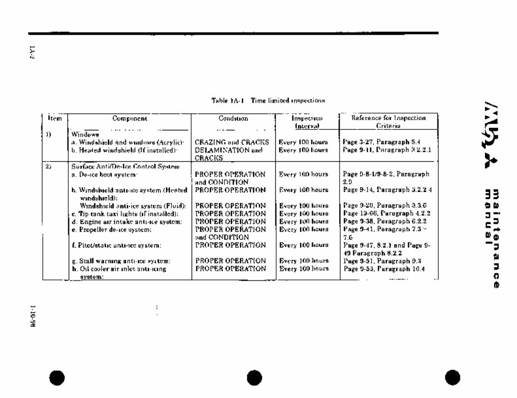
Table 1A-l Time limited inspectionsL\
Item Component Condition Inspection Reference for InspectionInterval Criteria
I) Windows
a. Windshield and windows (Acrylic): CRAZING and CRACI(S Every 100 hours Page 3-27, Paragraph 5.4
b. Heated windshield (If installed): DELAMINATION and Every 100 hours Page 9-11, Paragraph 3.2.2.1
CRACI(S
2) Surface Anti/De-Ice Control Systema. De-ice boot system: PROPER OPERATION Every 100 hours Page 9-8-1/9-8-2, Paragraph
and CONDITION 2.9
b. Windshield anti-ice system (Heated PROPER OPERATION Every 100 hours Page 9-14, Paragraph 3.2.2.4
windshield): 33Windshield anti-ice system (Fluid): PROPER OPERATION Every 100 hours Page 9-20, Paragraph 3.3.6 9) 9)
c. Tip tank taxi lights (if installed): PROPER OPERATION Every 100 hours Page 13-66, Paragraph 4.2.2
d. Engine air intake anti-ire system: PROPER OPERATION Every 100 hours Page 9-38, Paragraph 6.2.2
e. Propeller de-ice system: PROPER OPEE?1ATION Every 100 hours Page 9-41, Paragraph 7.3- rC
and CONDITION 7.6 9) (9f. Pitot/static anti-ice system: PROPER OPERATION Every 100 hours Page 9-47, 8.2.1 and Page 9-
49 Paragraph 8.2.2
g. Stall warning anti-ice syEtem: PROPER OPERATION Every 100 hours Page 9-51, Paragraph 9.3
h. Oil cooler air inlet anti-icing PROPER OPERATION Every 100 hours Page 9-53, Paragraph 10.4
m:

CHAPTER
GROUND HANDLING,SERVICING AND
REPAIR

maintenancemanual
CHAPTER II
GROUND HANDLING, SERVICING AND REPAIR
CONTENTS
PAGE
1. GENERAL ´•´•´•´•´•´•´•´•2-1
2. GROUND HANDLING 2-1
2.1 JACKING 2-1
2.2 MOORING ´•´•~´•2-3
2.3 HOISTING
2.4 LEVELING´•´•´•´•´•´•´•´•´•´•´• 2-7
2.5 TOWING´•´•´•´•´•´•´•´•´•´•´•´•´• 2-7
2.6 TAXIING ´•´•´•´•´•´•2-10
2.7 PARKING ´•´•´•´•2-10
2.8 FUSELAGE DRAIN 2-11
3. ENGINE GROUND RUN´• 2-12
3.1 FEATHER VALVE TEST 2-12 I3.1A STARTING TEST 2-12
3.2 NEGATIVE TORQUE SENSOR (NTS) TEST 2-12
3.3 OVERSPEED GOVERNOR (OSG) TEST 2-12
3.4 PROPELLER BLADE LOCK TEST 2-12
3.5 OPERATION TEST 2-(13)/143.6 ANTI-ICING AND DE-ICING 2-(13)1143.7 CONTINUOUS IGNITION EQUIPMENT TEST (Ifinstalled) 2-15
3.8 NORMAL STOP TEST 2-15
3.9 UNFEATHER TEST 2-16
3.10 EMERGENCY STOP TEST´• 2-16-1
3.11 TURNAROUND 2-16-2
4. STORAGE OF ENGINE 2-16-2
5. SERVICING 2-26-2
5.1 ENGINE OIL CHANCE AND REPLACEMEMT OF FILTER
ELEMENT 2-16-2
5.2 LUBRICATION 2-17
6. REPAIRS ´•´•´•´•´•´•´•´•2-37
6.1 SEALING ´•´•´•´•2-37
6.2 INTEGRALTANKSEALING 2-45
6.3 PRESSURE-TIGHT SEALING 2-48
1-10-98 2-i

maintenancemanual
6.4 WATER-TIGHT SEALING 2-50
6.5 SELF CONTOURING SEALING 2-51
6.6 REPAIR OF FIBER-GLASS REINFORCED POLYSTER-RESIN
SKIN ´•´•´•´•´•´•´•´•2-51
6.7 REPAIROF CABIN FLOOR 2-53
6.8 REPAIR OFACRSLIC WINDSHIELD 2-53
6.9 REPAIR OF BOOTS 2-55
6.10 REMOVAL OF BOOTS 2-57
6.11 INSTALLATION OF RUBBER BOOTS 2-58
6.12 REPAIR OF STATIC CONDUCTIVE COATING 2´•60
6.13 REPAIR AND REPLACEMENT OF DOOR RUBBER SEAL 2-61
7. AIRFRAME AND SKIN 2-(63)64
8. ACCESS DOOR 2-66
8.1 MAINTENANCE PRACTICE 2-66
9. INSTALLATION TORQUE 2-69
10. WEIGHT AND BALANCE 2-77
10.1 GENERAL DESCRIPTION 2-77
10.3 MEASUREMENT, CALCULATION AND CHECK OF WEIGHT AND
BALANCE ´•´•´•2-77
10.3 EQUIPMENT NAMES, WEIGHTS AND CENTER OF GRAVITY 2-77
11. CHAIN WEAR LIMITS- 2-78
11.1 VISUAL INSPECTION´•´•´•´•´•´•´•´•´• ´•´•´•2-78
11.2 MEASUREMENT OF CHAIN WEAR 2-78
12. NONDESTRUCTIVE INSPECTION´•´• 2-79
12.1 X-RAYINSPECTION ´•´•´•´•´•´•´•´•´•´•´•´•´•2-’79
12.2 FLUORESCENT LIQUID PENETRANT INSPECTION 2-83
1,3.3 MAGNETIC PARTICLE INSPECTION 2-85
2-ii 1-10-98

C~A ni a I nfe:n a a c aal 81 lil iii ~i I
i. GENERAL
prformed most freqliently during rou.tine operatio;n, and is intended as a guide for
This chapter for servicing and maintenance whic:h are
mecBaliics engaged in routine and periodic irispections, repairs and servicing.For serjicing and of s‘ji~tems not described’in this chaDtep, see the
respective chapter.
2. GROUND HANDL~NG
When hanciling. the ai~llie on the ground, observe the following:
(1) Do nbt lock control surfaces while t~owing or I;ajiiing the airplane.(2) Do not set parking brake if brakes are overheated.
(3) Before starting engine.
(a) Remove all towing ecluipment.(b) Head airplane into wind and chock wheels.
(c) All personnel, work stands andequipments sha.ll be clear of djngerous area.
(d) Retrieve control surface locks.
(e) Set parking brake.
(f) Remove engine intake and exhaust covers;
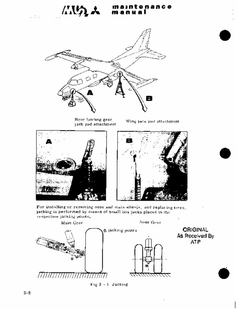
2.1 JACKING (See Figure:Z-l)2. 1~1 REQUIRED GROUND~ SUPPORT EQUIPMENT
(1) Jack~pad FWD fuselage GSE. 016A 99050
Wing GSE. 016A 99069-1´•; -2 (*1)GSE. 016A´•- 99069-31, -32
(2)~ Jack Fuselage more than i, 300 Ibs. (600 kg)
Wing Capacity more than 8; 800 Ibs. (4,000 kg)
2. i. 2 PROCEDURE
(1) Remove screws on the- under surface of wings, outboard of each nacelle
iW. S. 2560). and fuselage STA1275, and attach jack pads.
(2). Po$ition jacks underthe jack pads and, keeping airplane level; ~raise
airplane until the landing gears lea~e the ground.
CAUTION
(i) Avoid jacking airplane outside hangar
during gusty wind~conditions.
~ii): ~Avoid jacking onlthe insecure
there is the pos’sibili1 ty of ai.rplane slippingoff theli:ack,
(iii) It is recommended to drain fuel tanks before jackingai rplane. Especially iti.s desired to~drain tip tanks
less than half.
*1 Aircraft S/N’652SA:anl 661SA
*2 Aircraft S/N:6q7SA and subsequent 2-1
PtP b~ i a t e ri a iri~ c a
tn d a ~i a
O
Nose landing gear Wing jack pad attachmentjack pad attachment
J´•PL-’~- :IEi~f I
I r
~i
;"B.ii"
’3tS,id
For installing or removing nose and main wheels, and replacing tires,jacking is performed by means of small box jacks placed in the
respective j acking point s.
Main Gear Nose Gear
’9 jacking points ORIGINAL
As Received ByAT P
Fig 2 1 Jacking
2-2

ma~ntenancenl a a a a I
2.2 MOORING (See Figure 2-2)
Mooring procedures are variable fO~’ anticipated wind speed ranges of lessMooring prOcedurPa
than 20 kt (23 mph), 20 kf yo 60 kt (23 69 mph) and abwe 60 kf (69 mph)´•
z.z.l REQUIRED GROUND SUPPORT EQUIPMENT
(1) Gustlock plate Rudder GSE. 016A -99006
Elevator GSE. 016A- 99007
(2) Cover Engine air intake GSE. 016A 99010
Engine tail pipe GSE. 016A 99011
Pitot tube GSE. 016A 99015
Windshield GSE. 030A- 99016
(3) Wheel chock GSE. 016A- 99021
2.2.2 PROCEDURES
(1) When wind speed is less than 20 kt (23 mph).
(a) Raise flaps, lock rudder and elevator with gust locks, set trim tabs
in neutral position and set parking brake.
(b) Chock the main wheels fore and aft.
(c) Cover windshield, pitot tube, engine air intakes and tail pipes.
(d) Tie the nose wheel and tail skid.
(2) When wind speed is 20 to 60 kt (23 to 69 mph).
Tie down wings at W STA 4738,5.
(3) When wind speed is more than 60 kt (69 mph), hangar airplane.
Icaurlo41CAUTION
(i) For tie down, use over 1/2 in. (13 mm) manila
rope or rope having over 2,200 Ibs. (1,000 kg)breaking strength. For mooring procedures,see Flg. 2-2.
(ii) When strong wind is anticipated, head airplaneinto wind and maintain sufficient distance from
neighboring airplanes.
ORIGINA~As Received BY
ATP
2-3

maintenancemanual
a6
12 IN. (305 mm)
ii
NOSE GEAR TIE DOWN WING TIE DOWN EMPENNAGE TIE DOWN
1. WHEEL CHOCKS2. ENGINE INTAKE PLUG
3. ENGINE EXHAUST PLUG
4. PITOT TUBE COVER
5. RUDDER GUST LOCK PLATE
6. ELEVATOR GUST LOCK PLATE
7. WINDSHIELD COVER (IF EQUIPPED)
Fig 2-2 Mooring
2-4 3-31-90

~P1 ii B iia t is ~n i i14as~ ii si~ ill LP s
2.3 HOTSTING
2.3.1 REQ’CTI~.ED GROU~D SUPpORT
(1) sling Aft fiiseigge CISE. 01GA -9(3046
Wing GSE. d16A -99025-11
Fhselage GSE. 016A -99026-11
C;omplete airplane GSE. 016A 99027-11
~i) ’c-i´•arie Capacity Ik~ore th~an 22,600 Ibs. (11 tons)
2.3.2 PROCEDURE
(1) Empty fuel tanks.
(i) Hoist complete airplane´• As illustrated in Fig 2-3
Hoist fuselage As illustrated in Fig 2-5
Hoist wing As illustrated in Fig 2-4
Hoist aft iuselage 1 As illustraied in ~’ig 2-6
(3) Hook the shackle of sling and hoist slowly by cr´•ane.
da
(_.´•i
Fig 2 3 Hoisting
2-5

~enl an a a I
Fig 2 4 Hoisting wing
kl~P 61~7 1\
ialY--´•-
‘h---´•
A
Fig 2 5 Hoisting fuselage Fig 2 6 ’Hoisting aft fuselage
2-6
in a i nt. a a b a a g
m gaiua8
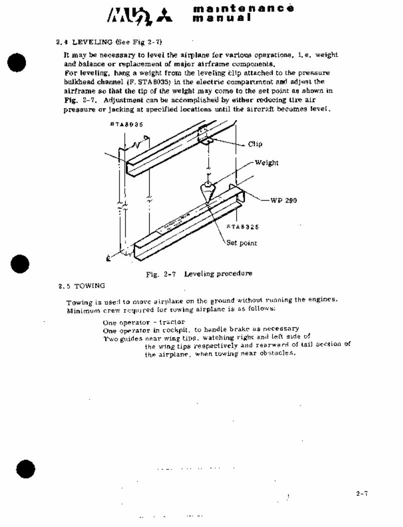
2, 4 LEVELIN~G (See %ig 2-7)
It may be necessary tb level th’i~ airplane for various i. e. weightand balance or i’eplacenient of major airfi´•ari~e components.For leveling, hajng a iYeight from the levelii~g blip attachedl to the pressure
bulltheaci channel STA8035j in the electi´•ii: compartment and adjust the
airf~ame so that t’he tip of the weig~ht maj~ come to the set point as shown in
Fig, 2-7. Aajustme~it can be acdomplished by either reducing tii´•e air
pressJre or jacking at specified locations until the aircraft becomes level.
a TA80 85
/i~´•*I Clip
1. I~Weight
IWP 290
sTA8325
Set point
aFig. 2-7 Leveling -procedure
2.5 TOWING
Towing is used to move airplane on the ground without running the engines.
Minimum crew.required for towing airplane is as follows:
One operator tractor
One operator in cockpit, to handle brake as necessary
-Two guides near wing tips, watching.right andleft side of
the wing tips respectively and´• rearward of tail section of
the airplane, when towing near obstacles.
2-7

pn a r n t a a a ii c a
an ia a a al
2. 5. 1 REQUIRED GROUND SUPPORT EQUIPMENT
(1) Toiv bar -:GSE Oi6A-99078-2i or equivaient
(2) Tow tractor
2. 5. 2 PROCEDURE
(1) Make sure that airplane is clear of obstacles, ground support
equipment, etc.
(2) Remove wheel chocks and check for normal tire pressure.
CAUTION
Before towing, disconnect nose landing gear torquearm connection. Re-connect after towing.
(3) Attach the ~tow bar in the holes in the nose wheel axle.
(4) Avoid jerky motion with tow tr´•actoi-. Tow tractor speed should not
exceed 5 MPH.
(5) If airplane is turned at a sharp angle, tires of main landing gear will
drag. Therefore, avoid sharp turns. Tow airplane with turning radius
as great as possible.
CAUTION
Tail skid s~zould not be used for towing. Never.
push, pull or lift airplane by control surfaces,tail cone, nose of fuselage, nacelles or pitot tube.
2-8

m a i a t a a a a a a
manual
o
DISTANCE LEFT EFFECTIVITY
ft.(m) ft.(m)
114.5(34.9) 104.0(31.7) *1
A 107.6(32.8) 110.9(33.8) *2
75.5(23.0) 65.0(19.8) "1
B 68.2(20.8) 71.5(21.8) *2
38.7(11.8) 33.5(10.2) *1
C 35.1(10.7) 36.8(11.2) *2
83.0(25.3) 72.8(22.2) *1
D 76.1(23.2) 79.4(24.2) *2
*1 Aircraft S/N 652SA
"2 Aircraft S/N 661SA, 697SA and subsequent
Figure 2-8 Minimum Turning Distances
3-31-90 2-9
maintenancenl a a u a I
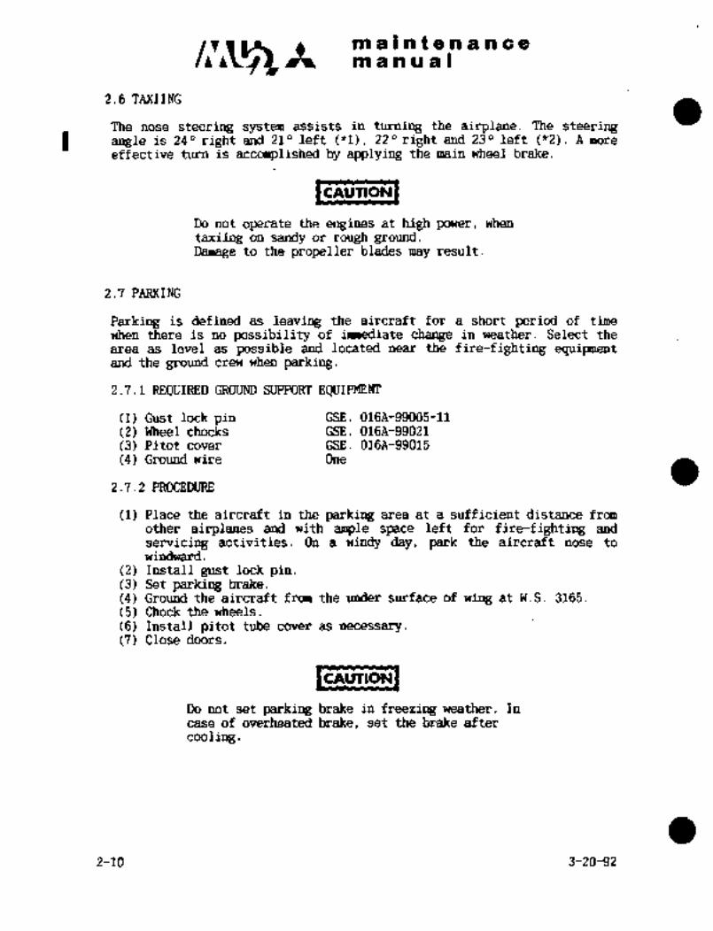
2.6 TAXIING
The nose steering system assists in turning the airplane. The steeringI angle is 240 right and 210 left (*1), 220 right and 230 left ("2). A more
effective turn is accomplished by applying the main wheel brake.
CAUTION
Do not operate the engines at high power, when
taxiing on sandy or rough ground.Damage to the propeller blades may result.
2.7 PARKING
Parking is defined as leaving the aircraft for a short period of time
when there is no possibility of immediate change in weather. Select the
area as level as possible and located near the fire-fighting equipmentand the ground crew when parking.
2.7.1 REQUIRED GROUND SUPPORT EQUIPMENT
(1) Gust lock pin GSE. 016A-99005-11
(2) Wheel chocks GSE. 016A-99021
(3) Pitot cover GSE. 016A-99015
(4) Ground wire One
2.7.2 PROCEDURE
(1) Place the aircraft in the parking area at a sufficient distance from
other airplanes and with ample space left for fire-fighting and
servicing activities. On a windy day, park the aircraft nose to
windward.
(2) Install gust lock pin.(3) Set parking brake.
(4) Ground the aircraft from the under surface of wing at W.S. 3165.
(5) Chock the wheels.
(6) Install pitot tube cover as necessarv.
(7) Close doors.
CAUTION
Do not set parking brake in freezing weather. In
case of overheated brake, set the brake after
cooling.
2-10 3-20-92

It maintenancemanual
2.8 FUSELAGE DRAIN (See Fig 2-9)
The water drains are operated by pushing the valve up slightly with a rod, etc.
r~ ~u
´•w
o ol Ln
u, ~n oIo hi
ED ~nl corto
v, vl
C~J ~II Lr
Ola o
.s B El -F~ C
I’’io 4’P (30’h~h;
4. Ptc~D Access door
F~a26(30
Drain valveo B (iP~
9
8 PtE~g~tC’ I
130a~R~Bio rorh/
Drain valve
Drain valveD
c 4´•;
Io"tt~o
Drain valve ~X @0~1P Q
~’II)4’
cj ~agDrain valve L~/´•e
0. 22 in.dia.
(5.5 mm)
*1 S/N 652SA
1~ *2 S/N 661SA, 697SA and subsequent
Push
Fig 2-9 Drain valve 2-11

maintenancemanual
3.’ ENGINE GROUND RUN
Occasionally it becomes necessary to pull (turn) the engine through by hand. Turn in the
direction of normal rotation only, due to possible damage to engine component parts.
Perform engine ground run in the following manner at the 100 hour periodic inspection,
except Para. 3.2 and 3.3 which shall be performed at time intervals specified in the
applicable flight manual.
(1) Required ground support equipment
Wheel chock GSE. 016A-99Q20 or Equivalent
(2) Preparation
(a) Set wheelchocks.
(b) Apply parking brake.
(c) Make sure that there are no safety hazards around airplane.
3.1 FEATHER VALVE TEST
Perform Feather Valve test in accordance with paragraph FEATHER VALVE CHECK in
Section 5 "NORMAL PROCEDURES" of the applicable FAAApproved Airplane FlightManua’.
3.1A STARTING TEST
Start engine and confirm items per applicable FAAApproved Airplane Flight Manual Section
"NORMAL PROCEDURES" paragraph "Before Starting Engines" and "Starting Engines.
3.2 NEGATIVE TORQUE SENSOR (NTS) TEST
Perform NTS test in accordance with paragraph NEGATIVE TORQUE SENSOR CHECK,
"NORMAL PROCEDURES" Section of the applicable flight manual.
3.3 OVERSPEED GOVERNOR (OSG) TEST
Perform OSG test in accordance with paragraph OVERSPEED GOVERNOR CHECK,
"NORMAL PROCEDURES" Section of the applicable airplane flight manual.
3.4 PROPELLER BLADE LOCK TEST
Perform propeller blade lock test in accordance with paragraph STARTING ENGINES step
14, "NORMAL PROCEDURES" Section, of the applicable airplane flight manual.
1-10-98

c~Amaintenancemanual
3.5 OPERATION TEST fl Aircraft S/N 652SA
Check the following items. *2 Aircraft S/N 661SA, 697SA and subsequent
Operating Item Power Lever Condition Lever Item to be checked
1. LOW SPEED GROUND IDLE TAXI 1. Ensure engine speedTAXI I i I is 64 to 66% RPM
(fl), 76.5 to 78.5%RPM (*2).
2. Beta Light normallyilluminated.
3. Oil pressure min.
40 psi.
4. Fuel pressure min.
15 psi.
5. No Caution Lightsilluminated.
2. HIGH SPEED GROUND IDLE TAKEOFF-LAND 1. Engine speed must be
TAXI 96 to 97% RPM.
2. Beta Light must be
illuminated.
3. TAKEOFF TAKEOFF TAKEOFF-LAND 1. Engine speed must be
POWER 99.5 to 100.5% RPM.
POSITION
2. Oil pressure must be
70 to 120 psi.
3. Beta Light must be
off.
4. REVERSE REVERSE TAKEOFF-LAND 1. Engine speed must be
94.5 RPM.
2. Beta Light must be
illuminated.
5. ENGINE TAKEOFF TAKEOFF-LAND 1. Engine power must be
POWER I I I limited at TorqueLIMITING 100% or ITT 923 "C.
Perform this test with setting "CABIN AIR SELECT" switch to "OFF" or "RAM"
position.
3.6 ANTI-ICING AND DE-ICING
(1) The loadmeter should deflect to operating range when the prop De-Ice
switch is placed to ON position and the Loadmeter selector placed to
the corresponding prop de-ice switch.
5-2-94 2-13(14)

c~ ~-tmaintenanceman ual
(2) The Oil Cooler Anti-Ice Indicator light should illumination when the
anti-ice switch is placed to the ON position.
I´•´•UrlONICAUTION
Oil Cooler Inlet Anti-Icing systemmust not be operated on ground for
more than 10 seonds.
(3) The Engine Intake Anti-Ice indicator should illuminate when theanti-ice switch is placed to the ON position.
IC*UTIONICAUTION
Engine Intake Heat Switch must not
be placed ON at an ambient temperaturecondition of 39"F (4"C) or above for
more than 10 seconds.
3.7 CONTINUOUS IGNITION EQUIPMENT TEST (If installed)
(1) Set "CONTINUOUS IGNITION" switch of LH and RH engine to "ON", one
at a time.
(2) Check to ensure igniter operates and "IGNITION" indicator lightilluminates for the engine set to "ON".
3.8 NORMAL STOP TEST
(1) Shut down engine in accordance with applicable flight manual.
(2) Check the following items.
(a) COAST DOWN TIME Approximately 50 to 60 seconds for each enginecoast down time should be about the same (time from setting the
RUN-CRANK-STOP switch to the STOP position until complete enginestops).
(b) Propeller stops in flat position by the action of propeller latch.
NOTE
Coast down time is apt to be affected by powerlever handling time, environment winds, etc.
Therefore, when abnormal incidence is found in coast
down time, determine whether the change is an
incidental one, or is steady abnormality based on dataof several operations. In the case of steadyabnormali ty, troubleshoot propellers, and en’ginesincluding engine accessories.
3-31-90 2-15

c~r Itmaintenancemanual
1. When abnormal incidence in coast down time occurs,
perform the below confirmation/check items as
follows.
(1) Confirm whether abnormal sounds exist and/orwhether the engines rotate smoothly, rotate
propellers by hand after engines stop.(2) Check damage for first stage compressor, or
contacts.
(3) Check FOD, overheating or cracks in third stageturbine wheel.
(4) Check damage or cracks in turbine rear supportstruts.
(5) Check any evidence of metal spray inside
tailpipe or at front surface of third stageturbine wheel blades.
(6) Check any abnormal metal particles in oil filter.
2. If an abnormality is not detected in the
confirmation/check, retry 3 to 5 more times to
determine if the original abnormality is an
incidental or steady condition.
3. In steady abnormality case of coast down time,troubleshoot propellers and engines includingaccessories
3.9 UNFEATHER TEST
Shut down engine with propeller in feather condition and check theunfeather function as follows:
(1) Set condition lever at TAXI and power lever at REVERSE.
(2) Push Prop UNFEATHER button until propeller latches actuate.
(3) Propeller can be set to flat pitch.
NOTE
It is recommended that operating time of propellerunfeathering pump be limited as follows: (both type I
and II Oil)(1) Oil in cool condition Max 1 min.
(2) Oil in operating temperature Max 30 sec.
When the above limit time is over, turn propeller withhands or crank by starter to drain oil from oil sumpin gear case until dip stick in oil tank shows FULL.
2-16 3-31-90

maintenancemanual
3.10 EMERGENCY STOP TEST
1CIUTIONICAUTION
This test should be performed only when emergency stopis necessary for inspection. Take care of the
following items.
(i) Perform this test after operation at ground idle
condition for at least 3 minutes.
(ii) Prepare fire extinguisher and connect external
power
(1) Slowly move the CONDITION LEVER to EMERGENCY STOP while watching the
fuel´•flow. Fuel flow should shut off prior to prop starting to
feather. When fuel flow shuts off, depress the STOP BUTTON to purgethe E P A After the E P A is purged continue moving the CONDITION
LEVER to feather the Prop.
1CnurloN1CAUTION
If turbine temperature rises abnormally after
operation of emergency stop, take the following action.
(i) Immediately place RUN-CRANK-STOP switch to "STOP"
position, then allow if to return to "CRANK"
position(ii) Return condition lever to TAXI.
(iii) Push UNFEATHER button and motorize engine bydepressing start button.
(iv) After engine reaches normal shutdown temperature,shut electrical system OFF.
(v) Inquire into the cause for abnormal rise of
turbine temperature.
(2) Place the following switches and circuit breaker OFF after enginestops completely.
FUEL MAIN switch
FUEL TRANSFER switch
FUEL BOOST PUMP circuit breaker
(3) Check the following items.
(a) Propeller stops in feather position.(b) Turbine temperature does not rise rapidly after engine stops.
3.11 TURNAROUND
If engine restarts are anticipated in 10 to 45 minutes.
3-31-90 2-16-1

c~ ctmaintenancemanual
1. Park airplane into wind if possible.
2. Manually turn engine rotating group in direction of normal rotation
occasionally to minimize thermal distortion.
NOTE
One blade width movement turns rotating group about
180 O
3. Continue these procedures until engine restart required.
L´•´•´•´•l~]CAUTION
Do not attempt to start an engine with thermal
distortion. Stagnate acceleration may occur between
the 184; to 2896 rpm range accompanied by a rapidincrease in ITT. Engine rotating group damage may
occur.
4. STORAGE OF ENGINE
In regard to preservation and depreservation of engine, see Maintenance
Manual for engine.
5. SERVICING
5.1 ENGINE OIL CHANGE AND REPLACEMENT OF FILTER ELEMENT
In regard to engine oil change and replacements of oil and fuel filter
elements, see Maintenance Manual for engine.
2-16-2 3-31-90
maintenancemanual
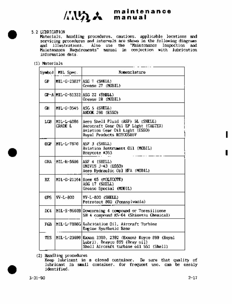
5.2 LUBRICATION
Materials, handling procedur~es, cautions, applicable locations and
servicing procedures and intervals are shown in the following diagramsand illustrations. Also use the "Maintenan~e Inspection and
Maintenance Requirements" manual in conjuction with lubrication
information data.
(1) Materials
Symbol MIL Spec. Nomenclature
GP MIL-G-238271ASG 7 (SHELL)Grease 27 (MOBIL)
GP-AIMIL-G-813221ASG 22 (SHELL)Grease 28 (MOBIL)
GH MIL-G-3545 ASG 5 (SHEU)ANDOK 260 (ESSO)
LGB MIL-L-6086 Aero Shell Fluid (ASF) 5L (SHELL)GRADE L Aerocraft Gear Oil EP Light (CALTEX)
Aviation Gear Oil Light (ESSO)Royal Products ROYCO586V
OGP MIL-L-7870 ASF 3 (SHELL)Aviation Instrument Oil (MOBIL)Braycote ~363
OHA MIL-H-5606 ASF 4 (SHELL)muIvIS 5-43 (ESSO)Aero Hydraulic Oil HFA (MOBIL)
RX MIL-G-21164 IRoex 65 (MOLYCOTE)ASG 17 (SHELL)Grease Special (MOBIL)
OPS VV-L-800 W-L-800 (SHELL)Petrotect 800 (Pennsylvania)
DC4 MIL-S-8660B IDowcorning 4 compound or Toresilicone
SH 4 compound KS-64 (Shinetsu Chemical)
FGB MIL-L-7808GI Lubrication Oil, Aircraft Turbine
Engine Synthetic Base
TES MIL-L-236991Exxon 2380, 2392 (E~xon) Royco 899 (RoyalLubri), Brayco 899 (Bray oil)Shell Aircraft turbine oil 551 (Shell)
(2) Handling proceduresKeep lubricant in a closed container. Be sure that quality of
lubricant in small container, for frequent use, can be easilyidentified.
3-31-90 2-17

maintenancemanual
(3) Cautions
a. Clean lubricated surface with clean solvent before lubricating.b. Keep quantity of lubricant applied to a minimum.
c. Wipe off excessive lubricant around press-in type fitting.d. Mixing of different greases is to be avoided.
If previously used grease is no Longer available, completelyclean and relube unit with another authorized grease.
(4) Symbols used in figures.
dWith hand With oil can With grease gun
NOT E
Should the time intervals not be defined
clearly at the lubrication points, refer to
the applicable MAINTENANCE INSPECTION AM)MAINTENANCE REQUIREMENTS Manual.
LUBRICATION CHART
FIGURE ITEM
2-10 Passenger entrance door
2-11 Emergency exit door
2-12 Nose landing gear door
2-13 Nose landing gear, steering and door mechanism
2-14 ~iain landing gear2-15 Landing gear retracting mechanism
2-16 MLG door mechanism
2-17 MLG door emergency release mechanism
2-18 Control column
2-19 Cable seal
2-20 Rudder pedal2-21 Elevator aft quadrant
2-22 Rudder trim tab actuator and hinge2-23 Elevator trim tab actuator and hinge2-24 Flap stop assembly2-25 Flap main gear box
2-26 Flap inboard auxiliary actuator
2-27 Flap main actuator
2-28 Flap outboard auxiliary actuator
2-29 Outboard flap guide link fitting
2-30 Outboard flap guide link mechanism
2-31 Trim aileron push rod
2-32 Spoiler feel spring2-33 Center pedestal assembly
2-34 Engine accessories
2-35 Engine control mechanism
2-35A Engine control torque tube/pulley2-36 Propeller2-37 Air conditioning and refrigeration unit
2-38 Flight chair
2-18 3-31-90

c~saa a a ;f 8 a a a a a
sta a a a is 1
J~´• GP
2 \1000H
GP~YI100011
5t 1000H
GP
1000H
cP
3 ~Y´•GP
GP ~YI 1000H1000H
6~U,46 GP
GP 1000H I
1000H´•\/5
GP
1000H
+GP1000H
GP
1000H
1000H
i. Rod end (Ib places) 4. ~Door hinge (2 places)
a 2. Gear (1 place) 5. Bracket (9 places)
3. Rod´•joint (9 places) 6. Press~re rod (1 place)
Pig. 2-10 Passenger entrance door
6-1-79 2-19
m a~ntenancem a a a a I
4 8
(IPY 9~0iP IOOOH
1
1000H 6~G OOP
100011
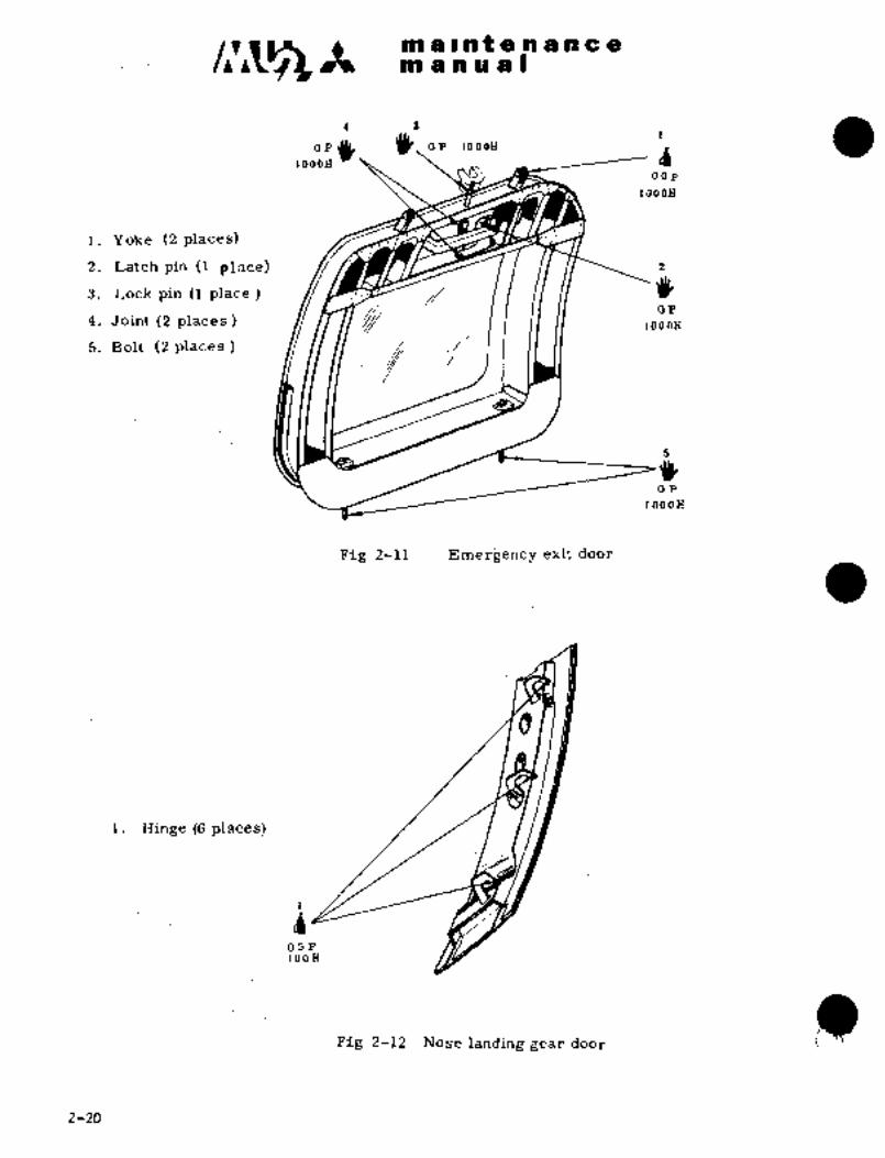
i. Yoke (2 places)
2. Latch pin (1 place) j3. Lock pin (Iplace)
4. Joint (2 places) P i i II ii5. Bolt (2 places
100011
Fig 2-1~ Emergency exit door
i. Hinge (6 places)
OCIP100H
ii)Fig i-12 Nose landing gear door
2-20

It m a a a a I
i1
´•Yt- oP At disasserribly1000H I
I
c~C ap
800H ._;t~X V~C=I
gOP-‘ c~p
’0.0 H ~ooH9 ~I MK---Zm7 ~y/V r~p ´•oP
8 OH n ri-?---l-~r´•-\ I 300H
300HOP 4
looH rC
15 a C)P100H
Or
OaAAt disassembly
4
After op100H
every yc:fli~ht or 5 C. Nose landing gear
~C 4. Drag strut assembly (L. H.100H IOOH
oP and R. H., 6 places)100H
S. Drag strut cam (L. W.
and R. i-i., 2 places)
6. noler (1 place)OHA
,After 7´• Trunnion lower bearing
every (1 place)flight s. Shimmy djmper attaching
point (2 places)12
9. Trunnion suppolt-fiteing13
Op (L1H. find n.H., 2llaces)100H
100H 3dOH~O. ´•Oleo_piston (Ip);~cc)oP oH
II; Upper torc´•1L’e link (2 places;A. Nose landing gear door mechanism
12. Upper and lo~er torrluc1. Spring cartridge (sliding surface, 2 places).
link joinC (1 place)
B. Steering mechanism 13.-: Lower torque linlt (2 I,lnces)
2. Crank/shaft (1 place) 1: Iq. Wheel be;iring
3. Cam rol-ler (1: place) ’15.‘ Shimmy damper piston outer surface(2 I,lrLc:es)
16. Inner spring (2 places) 17; T’cndu!i~n!(l´•
Fig.2-13 Noselanding gear,’st’eering anddoor mechanism
2-21

pjS1 a Ipi a a a g ri cc enr a a ai a I
15
91C’oP
OHA IOOH
After
every night C)b~~G 800H 5
113 00 H
13 R OP 300H
OP r)100H
9
CfP ..i/l I CtP
loo H I 100H
OP300H 7 4
10
It-’
‘lkI IoH
300H
7 8
yC ICa \RXOP
1 2 100H 100H
100H
OPS
G month
i. Wheel bearing (4 places) 8. Drag strut (2 places)
2. Leg end (4 places) 9. Drag strut joint (4 places)
3. Position rod (lower, 6 places) 10. Oleo lower support fitting (2 places)
4. Position rod (upper, 4 places) 11. Oleo piston (clean with oil, 2 places)
5. Leg pin’(4 places) 12. Oleo attaching pin (4 places)
6. Leg support fitting and pin (4 places) 13, Door mechanism rod (4 places)
7. Drag strut joint (4 places) 14. Wheel axle (cap inside, 2 places)
15. Pendulum (1 place)
Fig 2-14 Main landing gear
2-22

;3 1?
I;, d1.Torque tube spline (18 places)
;t´•See NOTE
GP;D LGB(D 1?
3. Sprocket (2 places) 134. Idler sprocket (1 place) RX d5. Chain (1 plaCe) d
LGB6. Emergency gear extension gear box (inside, 1 place) LGB
See NOTE7. Emergency gear extension gear box (1 place) See NOTE
8. Screw shaft (1 place) ’i9. Stop nut(l place)
10. Bearing bar (3 places)i.
11. Gear box and drag strut support (2 places)12. Balljoint (2 places)
14. Stop mechanism bearing box (2 places) GP13. Main gear box (1 place)
GP115. Actuator assembly (1 place)
GP
iy(e
U2´• GP
CP GP19
GPGP GP GP GP
100 H~JI 3GH
a3
P)P)
a
ax ir+
15 100 H9) (9
d 1
LGB4 GP P)
See NOTE At disassembly
RX16300 H
300 H rQGP GP
r)18 LGB
/C See NOTE (P/e GP16. Nose landing gear jack screw (1 place)
100 H
iiOGP
1 17. Pin (2 places)
GP 18. Rod end-(l place)
GP 19. Bracket-actuator attaching (2 places)GP I_GB
1000 H See NOTE NOTE
Replace lubricating oil at 1.000 hour or
3 year intervals whichever comes first.
w Fig. 2-15 Landing gear retracting mechanism
maintenanceman ual
TEMPORARY REVISION NO.P-~This Temporary Revision No. 2-1 is applicable to the following Maintenance
Manuals
MODEL NO. REPORT NO. PAGE
MU-2B-35/-36A MR-0218 2-24
MU-2B-60 MR-0336 2-24
Insert facing the page indicated above forthe applicable Maintenance
Manual.
Retain this Temporary Revision until such time as a permanent revision on
this subject is issued.
REASON To add lubrication of safety pin rod.
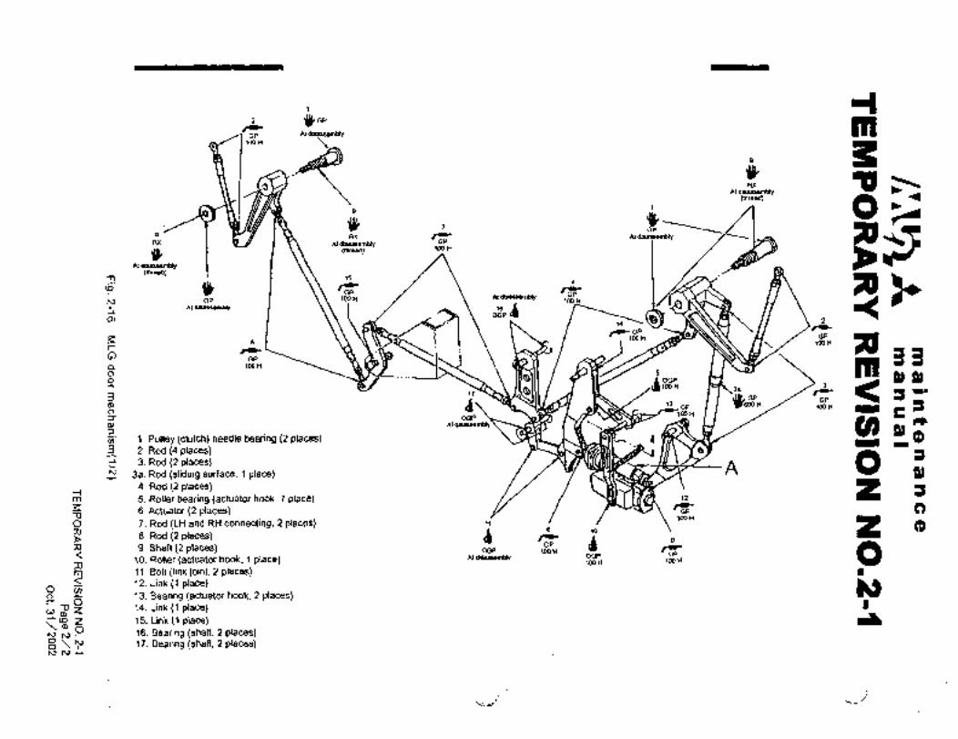
CHANGE Pig 2-16 (112) as follows.
TEMPORARY REVISION NO: 2-1
Page 1/2
Oct. 31/2002
2 g,, mGP AldisashemMy
tOOH
p$ 6a
Aldisasoemblythread)
i o~a ax rC At dls8ssembly FAtdlsassembly GP
i ehread) looH
Al d~assembly(\hread)
154 ’iP/e /i~k´•
G,.p loo H Al dlsessembly
100
OOPdAtdbassembly 18
2
/e GP1DO H 10OHGP
r
on 1MH33GP
mp,n,
,II~o/ 1 111- H 3
Ja rC3 IUL cP .GP
od ~imHO, GP ~M)OH 1WH 3
5r:
Atdlsassembly U) P, (PrC00 1. Pulley (clutch) needle bearing (2 places) I3 2. Rod (4 places) a
C~ 3a. Rod (sliding surface, 1 place)A: O P)
3. Rod’(2 places)
4. Rod (2 places)m~ 5. Roller bearing (actuator hook, 1 place) ~2
C)D
6. Actuator (2places)looHIGP
O 7. Rod~(LH and RH connecting, 2 places)i j
rir d(P
;o 0
z~ 8. Rod (2 places) 0
A 9. Shaft (2 places) GPOGP IOOH
OPAt dlaaasembly OGP
10. Roller(actuator hook, 1 place) \OOH 1M)H
m 11. Bolt (link joint, 2 places) i312. Link (1 place)O u,
13. Bearing (actuator hook, 2 places)O
~D Z 14. Link(l place)oP,-L 15. Link (1 place)(oZ
O 16. Bearing (shaft, 2 places)8 ~S 17. Bearing (shaft, 2 places)hlh)-~
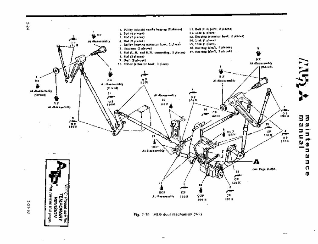
P i. Pulley (clutch) needle bearing (2 places) 11. Bolt (Hnk lolnt, 2 places)
2 k´•´• 3. Rod (2 places) 13. Bearing (actuator book, 2 places)2. Rod (9 places) 12. Lick (1 place)
IC 14. Link (1 place)oP
At disassembly 4. Rod (2 places)
LODH 5.. Rd~er bearing Iactuator hook, i placej 15. Link (1 place)
6. Actlator (2 places) IB. Bearlag (ahaft, 2 places)
j’I.:Rod (L. H. and R. H. connecnng, 2 places) 17. Bearing (ahalt, Zpl~cee)
8. Rod (2 places)0. Shaft (2 places) RX
10. Roller (actuator hook, 1 place) At dlsassembly t
8
7
(thrsad)
~C(tP
RX ´•I I t3\ RX OP ALdlaaaeemblyIOOH
At dlsassembly
(thread) 4At dlsassembly
15 TC(tbread) 6 /´•C
AtdlaaesemblyOP
OP LOOH
IOOHOP
B
;q /CGP
/clAt disassembly 2
14
aP100 K tOOH
aP ~Rr3 n ./uv/ P~ P)IOOH /eac
i OBP OP ~a100H 100 H CC
17OP r
dCD6 tOOH
OGP
Atdleaeaembly\~ ;=I
P)
,J
/e12
1~OSee Page 2-22A.
(D
II´• loo H
cp
6
b- i /CODP OP
6
ioo H loo HAt dlsaasembly IOOH OOP GP
o
-rn,
cb
Fig. 2-16 MLG doormechanism (1/2)o (0
i 81tRx
fd
C)
5 74 6 9
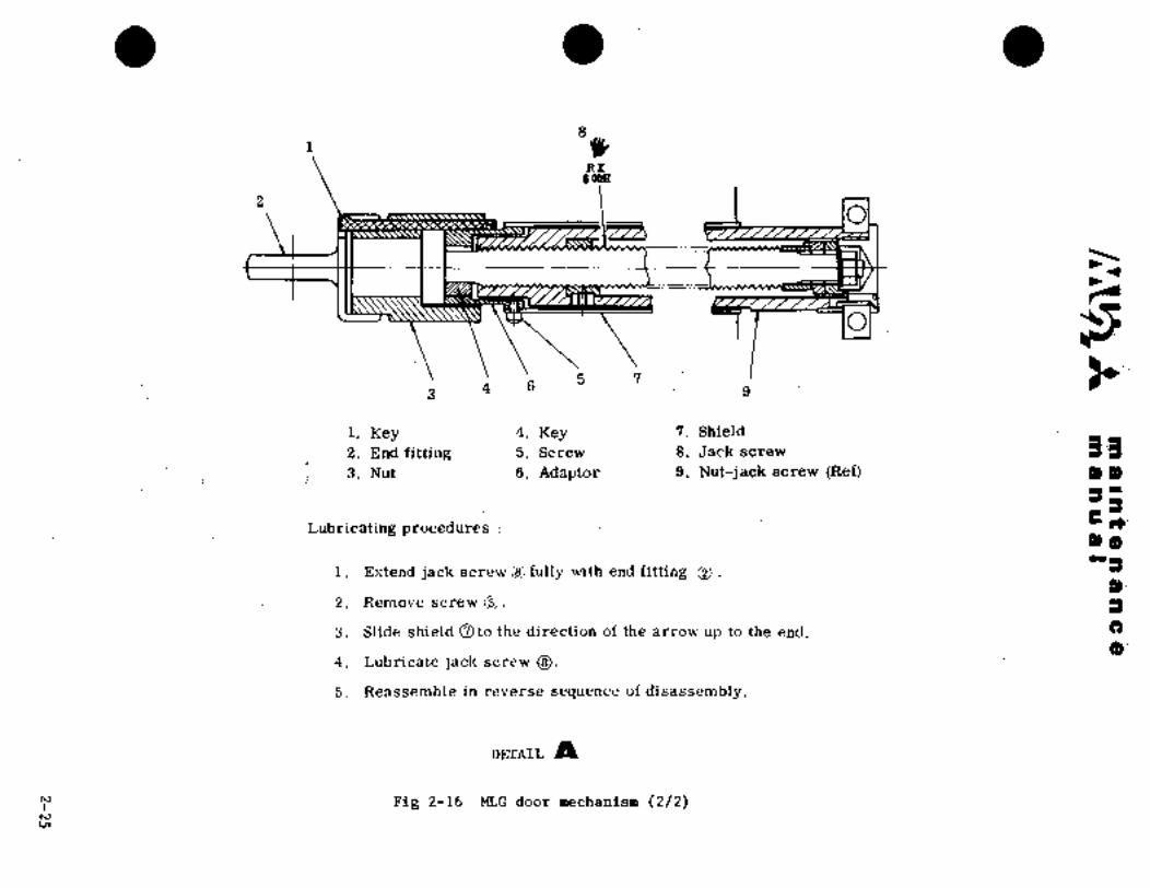
1.´• Key 4. Key 7. Shield2. End fittiag 5.s,,, s. Jack screw 3-9;3. Nut ~6. Adaptor: 9.- Nut-jack screw (Re4 3.
3-
3:3- c+:~Lubricating procedures1~.´•a0;:"3
i. Er;tend´•jack screw ~i fully with end fitting O’.8)´•
2. Remove screw O. 3’
3. Slide shieldOto the direction of the arrow upto´•the.end..
4. Lubricate jack screw
5. Reassemble in reverse sequence of disassemljly.
DETAIL Ig
Fig 2-16 MLG door mechanism (2/2)

CI~A in a II at e’a a a a 8
al a a Its a I
i O~P OOP O~PIOOH tBOH IbOH
OOPIOOH 10
b0OP
j II IOOH
i JtI.ax iO’OP
O i 10011 L OP
OBPsembly
bP 1001110011
13Atdisassemb?v
"rd,P a OOPu: OOP i
At disassembly1008
At dlsassembly i 1B i OOP DP
IOOH Atdtsassemb\y 100HOOPOP
10011 IsI
tdisased, d""’100H d embly
OoP
IOOHOOP
OP
OOP1. II/ ~Y 100H
lOOHa’
d At disa- 1;iooHju
OOP i ssemMy GP
LOOOH 5
,~P J~ JC 11 or,BIOOH
IOOH20CHOP
1000H g
OOP
OOP 8 At disassembl~´•OOPIOOHQ
i B OOPi iOOP
IOOOH0’
OOP IOOH
7 Atdisassembly100HId,P
10011
OOP AIOOOH
i. Cable terminal (15 places) 2. Fully nnoi; n~lnching point
3. Roller attaching point (6 places) (clutch, e plaues)
4. Door hook attaching shalt (4 places) 5. Lever attaching shaft
6. Hook and rod attaching point (4 places)
(pin, 4 places)7. Emergency gear extension lever 8. Linl-. ottAching shnft ii place)
(2 places)9. Spring pin attaching point 10. Crani: attaching jhaTt
(2 places) (3 plnces)
11, spring ~6 places) i?. IRnec -r.::e (1 places!
13. Bolt (I plncc) 1´•1. rc´•;~r,ue eubc, 1 (,lnce)
Fig 2-17 .MLG door emergency release mechanism
2-26

c,rs;rA ii a a a a
~P L~ Irn C
tOOH
b ~6.800H
O~P100H
i. Chain (1 place)
2. Sprocket (4 places) i. Cable seal (18 placesj
Fig 2-18 Control columnFig 2-19 Cable seal
i. Spring endi. Shaft(4 places)
fitting (6 places)2. Spring (1 place´•)
dre
Fig 2-21 Elevator aft quadrant900H
Fig 2-20 Rudderpedal
2- (27) 28.

c~amaiMfenancemanual
GP
1500 HGP 1. Chain (1 place)
j 1\Yt~RX
3. Rod (sliding surface, 1 place)1500 H 2. Actuator(l place)
4. Bush place)
i ?00 H
OGP
100 H
Fig 2-22 Rudder trim tab actuator and hinge
i 2. Actuator (2 places)Chain (1 place)
GP 3. Rod (sliding su~face, 2 places)1500 H RX 4. Bush (2 places)
i RX100 H
100 H 5. Hinge (8 places)
OGP
100 HGP
1500 H
Fig 2-23 Elevator trim tab actuator and hinge
2-29

maintenancemanual
2 6
5 300 H ,100 HGP GP
RX 1. Serration shaft (2 places)GP 100 H ´•Ss 2. Beailng (2 p\aces)
300 H 3. Screw shaft (1 place)4. Guide (1 place)
GP5. Nut(l place)
At disassembly7 7. Pin (1 placej6. Cam (Iplace)
´•j: GP
GP 100 H
At disassembly RX
100 H
Fig 2-24 Flap stop assembly
1. Serration shaft (2 places)2. Gear box (1 place)
NOTE
Replace lubricating oil at 1,000 hour or
GP 8 FGB3 year intervals whichever comes frst.
See NOTEAt disassembly
Fig 2-25 Flap main gear box
1 RX
50 H1.Jack nut (2 places)2. Jack screw (2 places)3. Pin (4 places)
O 4. Bolt (4 places)5. Serration shaft (4 placesj6. Gear box (2 places)
i 4dr 7. Bolt and pin (4 places)
GP3
50 H
GP100 H -Gp NOTE1500 H
6 1500 H Replace lubricating oil at 1,000 hour or
GP 3 year intervals whichever comes first.See NOTE 1500 H
Pig 2-26 Flap inboard auxiliary actuator
2-30 12-27-99
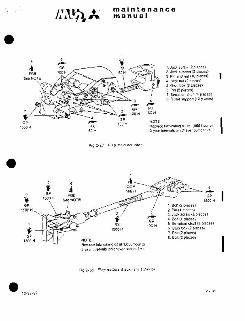
c~smaintenancemanual~
16 YI.i GP RX 01 1´• Jack screw (2 places)
FGB 100 H 50 H 2. Jack support (2 places)3. Pin and nut (16 places)
See NOTE4. Jack nut (2 places)5. Gear box (2 places)6, Pin (8 places)7. Serration shaft (4 places)
8 i 8. Roller support (12 places)
GP RX
4 GP3 100 H 100 H
GP /e100 H
NOTE
1500 H RX Replace lubricating.bil at 1,000 hour or
50 H 3 year interJals whichever comes first.
Fig 2-27 Flap main actuator
OGP 4100 H rC
GP o
1500 HFGB GP
See NOTE 1500 H
1500 H2
2, Pin (4 places)GP Bolt (2 places)
GP4, Bolt (4 places)3, Jack screw (2 places)
RX 5. Serration shaft (2 places)
1500 H100 H
6, Gear box (2 placesj7. Bolt ~2 places)
GP 8. Bolt ~2 places)1500 H NOTE
Replace lubricating oil at 1,000 hour or
3 year intervals whichever comes first.
Fig 2-28 Flap outboard auxiliary actuator
2-3112-27-99
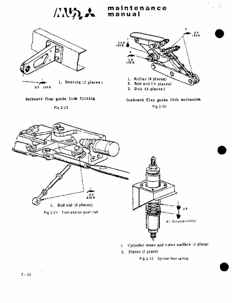
c~ltmaintenancemanual
o~1a0H
O P911 8
i. Roller (4 places)rC i. Bearing (2 places 2. Rod end (4 places)
OP 100H 3. Bolt (2 places)
Outboard flap guide link fitting Outboa~d flap guide link mechanism
Fig 2-29 Fig 2-30
1.
tOaa
i. Rod end (4 places) ´•dt-,,Fig 2-31 Trim aileron push rod i
At. disassc!ll~i,ly
i. Cylinder inner and outer surface (1 placet
2. Piston (1 place)
Fig 2-32 Spoiler feel spring
2-32
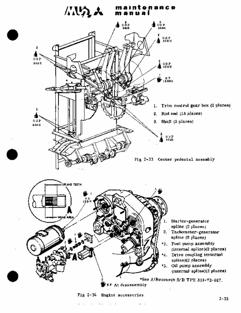
116~ ~o d a P
dO~P- dd~´•aOOH BOOH
b BOOH
O~P
i ~o´•osi
OP
i. Trim control gear box (2 places)
2 Rod end (18 places)
OCIP ~1 11,111 ~1 II 3. Shaft (3 places)800H
d 300H
Fig 2-33 Center pedestal assembly
SPLINE IEEfH
;j ax100H
A bO
WLAR
i. Starter-generator
1~2. Tachometer-generator
spline i2"places)
4
spline (2 places)3’~)(t
’3. Fuel pump assembly
(internal spline)(2 places)*4. Drive coupling (external
I spline)(2 places)*5. Oilpump assembly
(internal, spline)(2 places)
gB~ *See AiResearchS/B TPE 331-72-027.At disasse~mbly
Fig 2_34 Engine- accessories
2-33
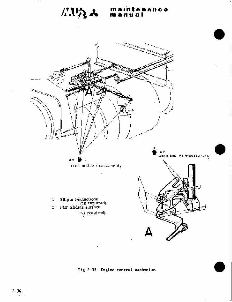
~-ci5 iai;a ;2 It;i t a a g ~i a
BBi a a I;i a O
C
I
a300H and At disassembly
~,P 3()´• 1
800H and At disassembly
ib::las required)
2. Cam sliding surface
las required)
A
Fig 2-35 Engine control mechanism
2-34

m la~ntenancgmaauall.
16~21 J~ Dc
Dc~t´• ’9 300H
300H
~T( ’i 1 ’JY´•´•e2 \u 30OH
Dc´•O~300H
i. Pulley (7 places)
2. Control ’Cable ´•(4 places)
Pi´•g.2-35A Engine control torque tube/pulley (1/2)
6-1179 2-346

m a at a a a a a a
m a a a a I
16~2
Jll´• Do
300H
Slt´• DC
300I~
A-A
Fig. 2-356 Engine control torque tube/pulley (2/2)
1 2-3486-1-79
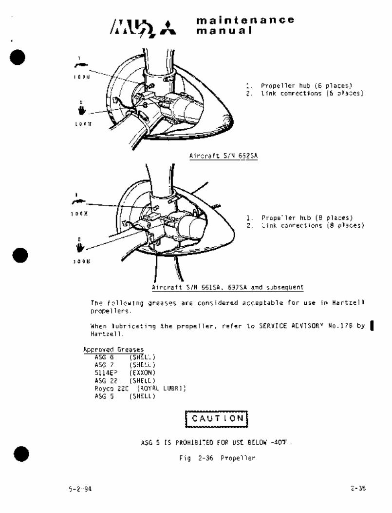
maintenancemanual
1 ~O\ ,il
100H
i. Propeller hub (6 places)2. Link connections (6 places)
LOOH
Aircraft S/N 652SA
100Hi. Propeller hub (8 places)2. Link connections (8 places)
100EI
Aircraft S/N 661SA, 697SA and subsequent
The following greases are considered acceptable for use in Hartzell
propellers.
When lubricating the propeller, refer to SERVICE ADVISORY Na.l7B by IHartzell.
Approved Greases
ASG~ (SHELL)ASG 7 (SHELL)5114EP (EXXON)ASG 22 (SHELL)Royco 22C (ROYAL LUBRI)ASG 5 (SHELL)
(CAUTloNJCAUTION
ASG 5 IS PROHIBITED FOR USE BELOW -409.
Fig. 2-36 Propeller
5-2-94 2-35

~3A ma~ntenancemanual
ij I/i
i?,t.
,n
Fig 2-37 Air conditioning and refrigeration unit
i´•´•At disassembly
i. Shaft las required)
Fig 2-38 Flight chair
2-36

maintenancem a n.u I
6. REPAIRS
In regard to repair of general structural parts, see Civil Aeronautics Manual 18, Maintenance, Repair,
and Alternation of Airframes, Power Plants, Propeller, and Appliances.
This paragraph provides only the repair instructions for specific structures.
6.1 SEALING
Seals consist of integral tank leakage protection seals, pressure tight seals, water tight seals, and self
contouring seals.
6.1.1 SEALANT MATERIALS
(Sealant) (Manufacturer) (Application)
Pro-Seal 890 A-2 Coast Pro-Seal A Teledyne Co.P’ecoat for integral tank and
brush sealing
Faying Surface Sealant for
Pro-Seal 890 8-2 Coast Pro-Seal A Teledyne Co. integral tank, Fillet Sealant.
Void Filler Sealant.
Pro-Seal 890 8-112 Coast Pro-Seal A Teledyne Co.Same as 8-2 quick hardeningtype
454-4-1 Top coating inside of the bottomFinch Paint Chemical Co.
Fungus Resistant Paint of tank
PR1221Products Research Corp. or
Yokohama Rubber Co. Pressure-tight Sealant
Products Research Corp. or Pressure-tight andPR1222 or PR14258
Yokohama Rubber Co. water-tight sealant
PR340 or PR341 or PS895Yokohama Rubber Co. self contouring sealant
Products Research Corp. or Water-tight and
Petrolatum
(VV-P-236)Self Contouring Sealant
Tape (JAN-P-127 Type IIPressure-tight sealingClass C)
12-27-99 2-37

c~~t main~enancemanual
/Cle.ningNaphtha Cleaning Acrylic Plastics for
(TT-N-95 Type ii) pressure tight sealing
MethylethylketoneCleaning(TT-M-261)
Toluene
(TT-T-548) Removing sealant
Leak Detector Turco Products Co. Detecting leakage
Cheese Cloth or Gauze Commercial Wiping for cleaning
Alodine solution
Alodine 1200 20-259Am. Chem. Product Corp. Treatment for metal surface
Nitric acid 2cc
Distilled water 1 I
Benzine Commercial Cleaning
Test tape Scotch No.?50 Minnesota Mining Mfg Co. Test for adhesion of topcoating
I6.1.2 CLEANING(1) Protect the area around repair from foreign material, contamination and scratches using thick
paper or cloth.
(2) Using a plastic scraper (preferably Nylon), remove sealant for approximately 1 inch width around
the area of repair.
Care should be taken not to remove sound sealant in the outer area.
(3) Cleaning of surfaces: After removing old sealant from area of repair, wipe the area carefully with
clean Cheese cloth or gauze saturated with Methylethylketone or Naphtha.
Immediately wipe the area with clean dry cheese cloth or gauze and allow the area to dry.
For cleaning acrylic glass, use Naphtha (TT-N-95 Type ii).
NOTE.
(i) After cleaning, do not touch the area with bare hands.
Use polyethylene gloves preferably.
(ii) Do not use a metal scraper, because it may scratch the aluminum clad surface.
2-38 12-27-99
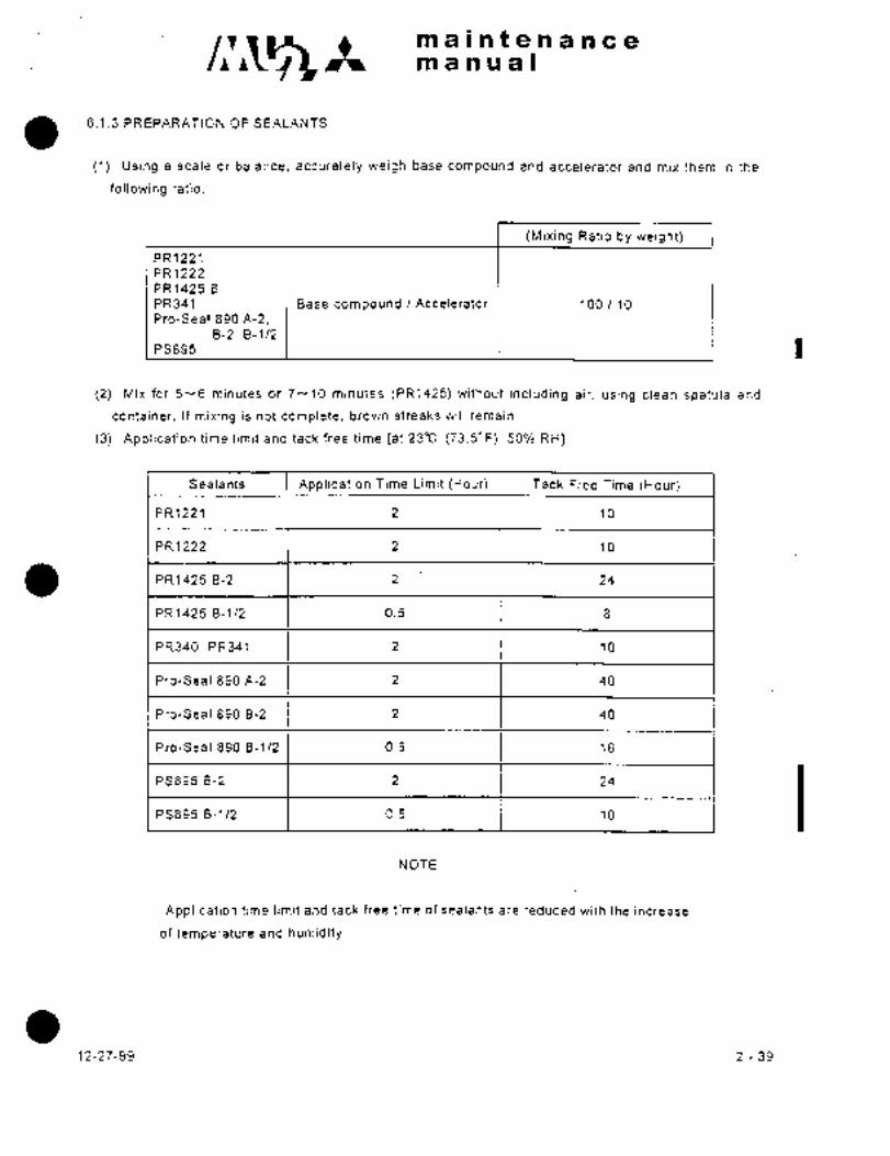
main~enancemanual
6.1.3 PREPARATION OF SEALANTS
(1) Using a scale or balance, accurately weigh base compound and accelerator and mix them in the
following ratio.
(Mixing Ratio by weight)
PR1221
PR1222
PR1425 B
PR341 Base compound /Accelerator 100 /10
Pro-Seal 890 A-2,8-2, 8-1/2
PS895 I
(2) Mix for 5--6 minutes or 7--10 minutes (PR1425) without including air, using clean spatula and
container. If mixing is not complete, brown streaks will remain.
(3) Application time limit and tack free time [at 23"C (73.5"F), 50% RH]
Sealants Application Time Limit (Hour) Tack Free Time (Hour)
PR1221 2 10
PR1222 2 10
PR1425 B-2 2 1 24
PR1425 8-1/2 0.5 8
PR340, PR341 2 10
Pro-Seal 890 A-2 2 40
Pro-Seal 890 8-2 2 40
Pro-Seal 890 8-1/2 0.5 16
PS895 8-2 2 1 24 IPS895 8-1/2 0.5 10
NOTE
Application time limit and tack free time of sealants are reduced with the increase
of temperature and humidity.
12-27-99 2-39

c~s maintenancemanual
(4) Curing: Standard time for curing is shown below. As it is affected by temperature and humidity, hot
curing with infrared lamp is preferable.
Standard time for curing at 23"C (73.5’ Fl 50% RH 14 days (36Hrs)
.48 hours (PR1425)
Hot hardening: One hour at room temperature, and 5 hours at 50- 55"C.(122--131.5" Fl
(5) Storage: Sealants (unmixed) packed in a closed container, if stored below 27"C(80.6"F), will be
effective for 6 months.
PR1425 (unmixed) in original unopened container, if stored at temperatures between 40
80" F (4.5- 27"C) will be effective at least 9 months.
Mixed sealants may be stored for 72 hours at -18--20"C (-1--4’ Fl.
6.1.4 APPLICATION OF SEALANTS
1 Sealing methods include faying surface sealing, fillet sealing, brush sealing and void filling. The typical
examples of applications are shown in Fig 2-39 below.
Tank inside Tank inside I Fillet sealing
Brush seaiing
"""Ou"ide UFayin~surfaceleaiingFig 2 39
6.1.5 FAYING SURFACE SEALING
(1) Fill the cartridge with sealant without including air. Using sealant gun with 57--100psi (4-
7kglcmt) pressure and 0,2in.DIA (5mmp~) nozzle, apply sealant continuously to one side of the
fastening holes laying beads.
Sealant 0.2 in. wide
Fastening holes on a straight line Fastening holes situated at random
Fig 2 40
2-40 12-27-99

manualntenance
(2) Have the faying surfaces fastened with rivets and screws within time limit of´•sealants, and remove
I) any excessive sealants with clean cloth saturated with toluene (or Naphtha TT-H-95 Type II for
acrylic glass).
(3) Sealants filled in fastening holes may be removed within the time limits as needed.
6.1.6 FILLET SEALING
(1) Apply sealant with spatula or gun avoiding inclusion of air, and form with spatula.
a2-41
12-27-99

c~slt maintenancemanual
(2) Apply sealant overlapping sound sealant in surrounding area by approximately 112 in. (13mm).
6.1.7 BRUSH SEALING
Apply two coats on rivet, bolt, nut and fillet seals with a brush free from loose bristles.
(1) Apply brushcoats after fillet sealant cures tack free.
(2) Apply uniform thickness without including air, overlapping brush sealant on the surrounding area
by approximately 1/2 in. (13mm).
(3) Apply the second brush coat after the first coat cures tack free.
6.1.8 TOP COATING
(1) Inspection
(a) Visually inspect inner surfaces of the wing integral tanks for evidence of discoloration, blistering
or folds of topcoating materials. (When there exists no such irregularity, no further action is
required.)
(b) If such an evidence is found to indicate faulty adhesion, determine the defected area by pressing
a topcoat with fingers or a plastic scraper to locate the spot where the topcoat peels off tank bottom.
(2) Clean up
(a) Defuel the tanks and wipe off residual fuel on the tank bottom with cheesecloth or gauze.
(b) Clean the area of faulty adhesion and adjacent area with benzine immersed clean cheesecloth or
gauze to remove any surface contamination together with any minor amounts of paint material
remaining.
Following this cleaning, the area should again be thoroughly cleaned using clean cheesecloth or
gauze and allow the area dry.
(3) Removal of defective topcoat
(a) Remove defective topcoat, using plastic or nonmetallic scrapers or test tape with the exception of
sealant applied area where scrapers should not be used, but finger tip, brush or test tape should be
used taking extreme care not to damage sealant.
(b) Apply a strip of one-inch wide test tape perpendicular to boundary between bared metal area and
adjacent topcoat. Press the tape down firmly by hand.
(c) The tape shall be removed in one abrupt motion perpendicular to the faying surface, by grasping
the tape by one end (the bared area side).
Whenever adhesion failures are observed, continue tape testing all edges of the coating
perpendicular to the coating edge, pulling away from the bared area, until steady adhesion of the
coating be ascertained.
2-42 12-27-99

C11~5 ~L itt a li.Plf a iii a 8
at a i~i ill a I
(4) Prepardti’bn of primer 454-4-1
~iix the following parts by volume, agitating the base material
trhile´• slowly adding accelerator: three parts of base material
454;-i;l;one part or accelerator. Allow material td stand for
3b minutes,then rea~gitate thorodghly. Allow material to catallzefor one hour prior to application. Maximum pot lifB of material
is 8~hours under normal temperatu~e conditions. After maximum
pot life, discard any unused catalyzed material.
(5) Recoating
NOTE
Sealant applied area does hot required recoat;ingof primer 454-4-1.
(a) Clean bared area and adjacent topcoated area one-inch wide from ~dge with
clean cloth’moistened with methlvlethyiketone (MEK). Exercise care in
cleaning DV1180/PR1005L applied area to keep MEIiout of the area.
DV1180 is subject to attacks of MEK solution.
(b) The cleaned area should be lightly scotch brited in conjunction with water.
Wipe the repair area with’clean cheesecloth or gauze and plain tap water.
Change the cloths and wash water frequently.
(c) Make sure that the affected areas are free of a water resistant nature.
Repeat the above steps (a) and (b) until water resistance’is eliminated.
id) Lay clean cotton cloths dampened with Alodine No. 1200 solution over
the hared metal area.
Care must be exercised not to allow Alodine solution in contact with the
surrounding’iritact coating or sealant.
(e) Allow Alodine solut;r~ to remain contacted with the metal surface for
approximately 5 minutes.
(f) Lay clean cheesecloth or gauze dampened with plain tap water over the
affected area. Never use scrubbingmotion.Change the cloths and water aS frequently as required to remove all residue.
(g) Lay and press down by hand clean, dry, lint-free cotton cloths over the
repair area.to dry it up.
(h) Let tank dry for 3 hours with air circulation after cleaning.Use ~special care while drying to prevent the.repair area from penetrationof dust and other contaminants.
2-43

c~a ni a i’n t a ;n a ii ~e a
m a ii ril a I
(i) Apply one uniform wet coat of primer 454-4-1 using good quality natural
bristle brushes.
NOT IE
(i) Dry film thickness should be approximately0.016 to 0.04 in. (0.41 to 1.02 mm). Do
not apply excessive amounts.
(ii) Ensure a minimum of 0.5 in. (13 mm) overlapof new primer over existing topcoating.Do not apply the primer beyond the scotch brited
area. Immediately wipe off excessive primerwith clean cloth dampened with MEK.
U) Allow to dry at least 24 hours under normal temperature conditions
before placing the tank in service.
The coating can be force dried for 1-1/2 hours at 500C (1220F),if hot air source is available.
c AU T 101J
Observe all warnings,cautions and notes on
material containers.
2-44

a a a a I
6.2 INTEGRAL TANK SEALING
6, 2, 1 TYPES OF LEAKS
Stain: Stain caused-by fuel seeping out of tank,
Action: Stains which do not affect flight safety; need not be
repaired immediately, but their development0, 24h´•0. 51 in,
should be checked periodically.DIA
(6 to 13 mm)
Seep: Advanced sta‘te’ of stain, a leak which reappears In a short period of
time after being wiped clean.
Action: Same as that for stains.
´•DIAi, 5 in, (38 mm)
Heavy Seep: A fuel leak which reappears immediately after it is wipedclean with cloth,
Action: Same as that for stains, When a leak occurs in
3.5´•c~4 in,a sealed portion on-the area other than outer
DIAsurface of wing, repair immediately.
(89 to 102 mm)
Running Leak: ´•Fuel flaws continuously out of tank and drips off wing.
Action: Repair immediately
4c5 in. DIA
~y (102 to 127 rmnll
I Fuel will usually begin to drip here..
2-45

in a;l n% a ii a a a a
in a a i~ a I
Cf. 2. 2 LOCATING LBAKTNi; AREA (See Fig2-41)
Ejven though a leakage is found on the outer surface of tank, the dCfective area
in the interior of tank.can not always be located immediately. The source of
leakage should be located in accordance with the following procedures before
attempting repair.
(1) Brush leak detector on the leaking area on ti~e outer surface of tank.
Do not ~pply to the inner surface of tank.
(2) Blow compressed air (max. 90 psi) that has been filtered by air cleaner to
the edges of fillet, and brush seals in the tank interior corresponding to
the leaking outer area as illustrated in P’ig 2-41´•
(3) Continue applying air until leak detector on the outer surface forms
bubbles.
NOTIE
Sealant may be peeled off by the compressed air.
Loosened sealant must be repaired whether or ´•Iiot
there ´•is leakage.
Leaking area
Apply leak detector
Air hose
Sealant
Nozzle
leak detector
L,eLlking area
Compressed air
90 psi(6. 31~glcm2) air
Fig 2 41 Locating leaking area
2-46.

.-m ain t~e nance
m’a n a a I
6.2.3 SEALING
6.2.3.1 GENERAL STRUCTURE (See Pig 2-42)
Perform faytingsurface sealing, fillet sealing, brush sealing and top coating in accordance with Para.
6.1. r\ r Faying surface sealingBrush sealing
Fillet sealingBrush sealing
(Precoat)
BOTTOM SEALINGFayinZ, surface sealing
UPPER PANEL I Brush sealing
Fig 2 42 integral tank sealing
6.2.3.2 BOLTS, SCREWS, RIVETS SEALS
(1) Apply brush sealant Pro-Seal 890 A-2 in accordance with instructions given in Para. 6.1.7.
Brush sealing
’i1/ 2 in. Min. (13 mm) 1/ 2 in. Min. (13 mm)
Sealant thickness 1/32 1/16 in (0.8-1.6mm)
(2) When replacing bolts, screws, or rivets, fill the holes with Pro-Seal 890 8-2 or B-t/2 using gun or
spatula and install clean bolts, screws or rivets in the holes after Pro-Seal 890 A-2 has been applied
to their shanks and´•beneath the heads with brush.
NOTE
Do not apply sealant to shanks, heads and holes for bolts and screws that are
installed with "O"ring washer or self sealing nut.
2-47

´•maintenancemanua~
6.2.3.3 VOID FILLING (See Fig 2-43)
All voids and holes in the tank that may cause leakage are sealed with Pro-Seal 890 8-2 or 8-1/2.
(1) Apply Pro-Seal 890 8-2 or 8-1/2 in a slightly excessive quantity with spatula or gun.
(2) Apply sealant to voids in the corners, in sufficient quantity to extrude when brackets are installed.
r’*
I´•!
A
A -A
Fig 2 43
6.2.4 LEAKAGE TEST
Ensure that curing of repair sealants is complete, seal all doors and holes except compressed air inlet,
and adjust internal pressure to 2.7 psi (0.19kglcm2) gage pressure using clean air that has been filtered
by air cleaner. Apply leak detector to the outer surface of the tank and inspect visually for 15 minutes.
NOTE
(i) Never allow internal pressure to exceed 3 psi (0.21kg/cm2).
(ii) Do not remove any seal before internal pressure falls to zero.
6.3 PRESSURE-TIGHT SEALING
6.3.1 SEALING OF GENERAL STRUCTURE (See Fig. 2-44)
Perform faying surface sealing and fillet sealing with
PR1222, PR14258 or PR1221 in accordance with Para.G.1.
Fig 2 44
2-48 12-27-99

c~amaintenancemanual
6.3.2 SEALING OFHOLES AND SLOTS (See Fig 2-45)
Apply sealant directly to holes with widths less than 118 in.(3mm).
Attach pressure sensitive tape (JAN-P-127, Type II, Class C) over the holes with width 1/8- 2/4 in.(3
-6mm) and apply sealant.
For holes with a width of more than 1/4 in.(gmm), fill with a rivet, balsa wood plug or cap so as to
reduce the opening below the 118 in.(3mm) max. and then seal with a layer of sealing compound,
extending a min, of 5/16 in.(8mm) from the edge of the hole.
W Sealing compound
Tape
H
Hole with 1/8 in.5/16 in. 1/8 114 in. (3- 6 mm)
(3mm) in Dia. max.(8mm) min.
\N=l /8 ’1116 in. (3+1.5 mm) Hole with 118 1!4 in.
-9 -O
(3--6 mm) in Dia.
H=1116+1/16 in. (1.5+1´•5 mm)-O -6 Fig 2 45
6.3.3 CABIN DOOR AND EMERGENCY DOOR (See Fig 2-46)Perform faying surface sealing and fillet sealing with PR1222, PR1425B or PR1221 in accordance with
Para.G.1.
Door
Fuselage
Fuselage 3 Door
Emergency door Cabin door
Fig 2 46
6.3.4 BOLT, SCREW AND RIVET SEALING
This type of sealing is performed where faying surface sealing is not practical.
Bolts, screws and rivets are sealed in accordance with the following procedures after all other sealinghas been compleied.
(1) Fill the hole with PR1222 or PR1425B using gun or spatula,´• and put a clean bolt, screw or rivet in
the hole after applying sealant’ to its shank and beneath the head with brush. Apply sealant’ to both
sides of wastier befole instailing.
Use a mixture of two parts of PR1222 or PR1425B with one part toluene.
12-27-99 2-49

c~h maintenanceman ual
(2) Apply brush sealant" in accordance with Para.4.1.7.
I Wle a mixtuie .i tw, psrfE of PR1222 or PRla258 wiih one ppri toluene
6.3.5 WINDSHIELDS AND WINDOWS (See Pig 2-47)
(1) Do not use any solvent other than Naphtha (TT-N-95, Type II) for cleaning.
(2) Do not use any sealant other than PR1222 or PR1425B for pressure-tight and self contouring
sealing.
(3) Apply a thin coat of petrolatum to retainer before installing.
(4) Apply sealant PR1222 or PR14258 to counter sink portion of screw head before installing.
1 (5) Use PR341 or PSB95 or PR340 for filletsealing on the outer suriace of airplane.
Have the foot of fillet aligned with the existing sound seal.
1.Water-tight seal
2. Self contouring seal
O 3. Pressure-tight seal
Windshields attaching screw2~\-´•1
2
Fig 2 47
NOTE
When part of pressure-tight seal is peeled off, noise increases. Locate and reseal
the area.
6.4 WATER-TIGHT SEALING (See Pig 2-48)
Water-tight sealing is performed for protection of fuselage mating ends and quick fastener receptacles
from water.
(1) Attach masking tape of approx. 3/4 in.(l8mm) width on both sides of gap so that exposed surface
with 1132- 3/32 in.(0.8-- 2.4 mm) width remains.
(2) Apply sealant, using sealant gun or wooden spatula. When a gun is used, place the nozzle of
sealant gun on the gap. Tilt the gun about 45" to the direction towards which the gun is running and
fill excess compound into the gap.
Squeeze the compound into the gap with a wooden spatula. Smooth the surface of applied
compound and remove excess compound.
(3) When sealing has been completed, slowly remove masking tape on both sides, smooth out the
edges with fingers immediately after removal of masking tape.
1 (4) Apply PR341 or PS895 or PR340 to outer suriace of airplane, and PR1222 or PR14258 to inner
surface.
2-50 12´•27-99

ni a i n t a n a n c ~emanual
Sealing compound Sealing compound
Fig 2 48
6.5 SELF CONTOURING SEALING
This type of sealing is performed around the lid of access door to protect the area from water.
(1) Apply PR341 or PS895 in ample quantity to airirame with gvn or bpatula. I(2) Apply petrolatum around lid of access door and to screws.
(3) Leave the assembly until sealant has completely cured.
(4) When a component, on which sealant has hardened, is disassembled, cut off protruding sealant with
a sharp knife and wipe off the applied petrolatum with a naphtha moistened clean cloth.
(5) Wipe off excess sealing compound with a methylethylketone or toluene moistened cloth before curing
(within approx. 4 hours after mixing).
6.6 REPAIR OF FIBER-GLASS REINFORCED POLYESTER-RESIN SKIN
The fuselage nose cone, tail cone, vertical stabilizer dorsal fin, rudder upper edge, and vertical
horizontal stabilizer tips and forward bulge of leading gear well are made of polyester-resin reinforced
with glass cloth.
6.6.1 CRACK REPAIR
(1) When the depth of crack is less than 0.008 in.(0.2mm).
(a) Smooth out cracked portion with sand paper (#300).
(b) Apply resin sealing.
Pour 1-2 parts of methylethylperoxide liquid into 100 parts of resin, approved in accordance with
MIL-R-7575 such as: Polylite 8010! Laminac 4128, or Vibrin 152, and 6% Naphtensan Cobalt liquid,
at 0.05%--0.2% weight ratio, agitate the mixture and apply with brush.
(c) Allow the patch to cold-cure for a minimum of 24 hours at room temperature, or for a minimum of 1
--2 hours under a temperature of 210" F(98.8"C), using an infrared lamp.
1~-27-99 2-51

C~gh maintenancemanual
WARNING
Do not mix methylethylperoxide liquid and 6% Naphtensan Cobalt liquid alone.
NOTE
Total amount mixed at one time should be less than 3.5 oz.(100g). Agitation should
be completed within 30 min.
(2) When the depth is more than 0.008in., leave repair to special shop.
6.6.2 PEELING REPAIR
(1) Polish the surface with #100--#300 sandpaper.
(2) Clean the surface with acetone or methyl-ethyl-ketone.
(3) Mixing of resin (weight ratio)
Epon 828 100
Diethylene-Tri-Amine (DTA) 8
(4) When the trailing edge of forward flap has peeled (See Fig 2-49), soak a sheet of glass cloth (#181)
in resin and attach it to the trailing edge.
Peeled FRPGlass cloth
1 ´•~:´•I´•rtc:
Pig 2 49
(5) When peeling has taken place between the foamed-plastics core material and cloth (See Pig 2-50):
(a) Remove 1 in. area around the peeled portion ~f the outer.skin.
(b) Soak glass cloth in resin and attach.
(6) When peeling has taken place between an aluminium member and cloth, glue with resin.
NOTE
Peeling within 112 x 1/2 in.(13 x 13mm) is serviceable.
2-52
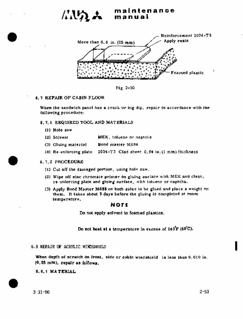
maintenancemanual
Reinforcement 2024 -T 3
More than 0. 6 in. (15 mm) APP?Y resin
00D
:Oo’´•o"´•
o o
C´•,I~ C~r C ,´•D,Qo 0_0 ]..O C.
~e Foamed plasticoD ´•’1
FoO
OO´•OC. od
Olncp´• I´• rl_EI~
Fig 2-50
6, 7 REPAIR OF CABIN FLOOR
When the sandwich panel has a crack or big dip, repair in accordance with the
following procedure:
6, 7. 3 REQUIRED TOOL AND MATERIALS
(1) Hole saw
(2) Solvent’ MEK, toluene or naphtlia
(3) Gluing material Bond master M688
(4) Re-inforcing plate 2024-T3 Clad sheet 0. 04 in. (1 mm) thickness
6. 7, 2 PROCEDURE
(1) Cut olfthe damaged portion, using hole saw.
(2) Wipe off zinc chromate primer on gluing surface with MEK and clean,
re-inforcing plate and gluing surface, with toluene or naphtha.
(3) Apply Bond Master M688 on both sides to be glued and place a weight on
them. It takes about 3 days before the gluing is completed at room
temperature.NOTL
Do not apply solvent to foamed plastics.
Do not heat at a temperature in excess of 140´°F (60´•C).
6.8 REPAIR OF ACRnLC WINDSHIELD
When depth of scratch on front, side or cabin windshield is less than 0. 010 in.
(0. 25 mm), repair as follows.
8.8.1 MATERIAL
3-31-90 2-53

c~z Itmaintenancemanual
Solvent TT-N-95 Type II
Castile Soap Solution Hock Weld Chemical Co.Fine Abrasive Type A5175 Linde Air Products Co.Glasticoate #18 R. Killon Industrial Co.
Waterproof Sand Paper U400, ~600, 8800
Flannel Cloth
6. 8. 2 REMOVAL OF SCRATCH
(1) Clean the surface of acrylic.(2) Rub the surface around the scratch with a circular motion within the limits
of 0.6 In. (15 mm) dla. by waterproof sand paper #400 wrapped around wood
or rubber block, keeping the sand paper wet,(3) Perform sanding with 600 sand paper same as para.. (2)(4) Perform sanding with 800 sand paper same as para. (2)
NOTE
Partial sanding on small area may warp the acrylicand give bad visibility. Sanding should be made on
a large area to prevent warping. Reduction of
thickness of the acrylic panel should not exceed 0.01in. (0.25 mm). If the panel is sanded beyond above
limits the panel should be replaced.6. 8. 3 REMOVAL OF SCRATCH BY ABRASIVE
(1) After sanding of acrylic, polish the sanded surface slightly with wet
flannel cloth with proper amount of fine abrasive.
(2) Polishing with fine abrasive should be continued until no scratch or
warp is on the acrylic.(3) Wipe the acrylic two or three times slightly with wet flannel cloth
with small quantity of Glasticoate #18. Glasticoate #18 is effective
for shining and keeping off dust.
NOTE
Do not rub the acrylic with hard cotton cloth or dried
flannel cloth. Wet flannel cloth should be used.
6.8.4 CLEANINGINSTRUCTION
(1) Blow dust off with shop air.
(2) Flush the pane with grit-free water and a mil’d soap solution to remove
all dust, mud, solvent, grease or other oily material, lightly rubbingwith a clean soft cloth, chamois or sponge. Rinse with clean water.
IcnurlorrlCAUTION
(a) The use of gasoline, benzene, acetone, carbon tetrachloride,fire extinguisher fluid, lacquer, thinner, toluol, isopropylalcohol, ethyl alcohol, neutral cleaner for´•automobile, etc.,is strictly prohibited, because the effects of those fluids,when introduced to the acryl.ic panes, will cause them to
craZe.or soften.
2-54 3-31-90
m a i at e-:~i a ~e ~e
m an a a s
(b) Cleaning of the acrylic panes should never be attemptedwhen dry to avoid making scratches on the surface andJor
acclu~ulating static electricity which would attract dust.
(c) Care must be exercised not to damage the surface of the
acrylic panes with a ring, jewel, belt buckle or other
sharp objects worn by worker while cleaning.
(3) For stubborne grease or oil deposits, use Soap Solution
Castile or Cleaner MIL-C-18761.
(4) When anti-icing fluid is used, the windshield glasses should
be flushed with clean water.
(5) Wipe off residu~al water and static electricity from the surface with
a soft clean cloth, chamois or sponge anti allow it dry.
6, 9 REPAIR OF BOOTS
6,9, 1 SCUFF DAMAGE
This type of damage will be most‘commonly encountered, and. it. is not.necessaryin most cases to m’ake a repair.. Repair is necessary if the scuff is severe
and has caused the riibber underneath to’be exposed.To repair the damage, proceed as follows:
Material required for repairs
a :~58EC-1403 or EC-1300L Cement 3M Cb
Ima Rubber Co.
Solvent Toluol or
MethylethylketoneMetal stitcher roller 0, 24 in.~(2i mm) in width
(1)IThoroughly clean the area around the damage with acloth dampened slightlywith solvent.
:(2)´• Buff the area with steel wool.
(3) Wipethe buffed area with a cloth, slightly dampened with solvent, to remove
allloose particles.
(4) PreDare a patch´•large enough to cover the damaged area,
(5) Apply one coat of ´•cement on the patch and the corres~ponding area of boots
and leave it:for 2h3 min;:
(6) Apply-the patch to the boot with the edge,’ or the center adhering first. Work
down the remainder of the patch carefully to avoid trapping air in pockets.Thoroughly roll the patch and allowto set for 10y15 min.
(7) Wipe the patch and surrounding area from the center outward.with a cloth
slightly dampened with solvent.
(8) Apply´•dne thin co’at´• of A-56B~ conductive cement and leave it for 4 hour~i
(9) Inflate hoots for at least 20 minutes for inspection.
2-55

iPIIlntenanceit~ a a u a I
i
6. s. 2 TEARS, RUPTtTRES qF TtTBE AREA
Cuts, tears or ruptures of tube area can be repaired with fabric reinforced
patches.
(1) Prepare a fabric reinforced patch of ample size to cover the damage and to
extend to at least 5/8 in. (16 mm) beyond the ends and edges of the cut or tear.
(2) Repair should be done in accordance with para. (1) except that emery buff-
ing stick isused for buffing.
(3) Apply the patch to the boot with the stretch in the widthwise direction of the
inflatable tubes, sticking edge of patch in place, working remainder down
with a slight pulling action so the injury is closed. Do not trap air between
patch and boot surface.
6.9. 3 LOOSE SURFACE PLY IN DEAD AREA (NON-INFLATABLE AREA)
Peel and trim the loose surface ply to the point where the adhesion of surface
ply to the boot is good.
(1) Scrub (roughen) area in which surface ply is removed with steel wool.
Scrubbing motion must be parallel to cut edge of surface ply to prevent
loosening it.
(2) Scrub with steel wool and toluol directly over all edges, but parallel to the
edges of surface ply in order to taper them down to the tan rubber ply.
(3)’Cut a piece of surface ply material large enough to cover the damaged area
(4)’1Mask off the damaged boot area 1/2 in. (13 mm) larger in length and width
and extend at least 6. 1 in. (2. 5 mm) in all directions.
than the size of surface ply.
(5) Apply one coat of EC-1403 to damaged boot and surface ply.
(6) Attach the surface ply material to the boot; roll the surface ply with rubber
roller, and roll edges with stitcher-roller.
(7) Apply just enough tension on the surface ply when rolling to prevent wrinklingand roll carefully to prevent trapping air. If air blisters appear, remove
them with a hypodermic needle.
(8) Wipe off excessive EC-1403 with solvent.
6. 9. 4 LOOSE SURFACE PLY IN TUBE AREA
This ´•type ~f failure is’ more easily detected in the form of a blister under the
surface ply when the ~boot is pressurized. If this type of damage is detected
while still a small blister [about 1/4 or 3/8 in. (6 or 9.5 mm) in dia; i and if
patched immediately, the service life of the boot can be appreciably extended.
6, 9. 5 DAMAGE TO FABRIC RACK PLY OF BOOT DURING REMOVAL
If cement has pulled loose from wing skin and adhered to the back surface of
boots, remove.it with steel drool anclMEK. In those spots where the coating has
pulled off the fabric, leaving bare fabric exposed, apply at least two additional
coats of cement EC-´•1403. Allow each coat to dry thoroughly.
2-56
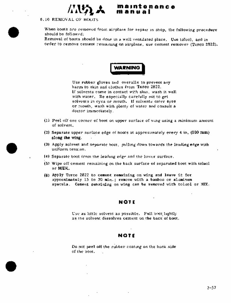
ni a ii ri~ a Iiiri a I iii;a -~iri a ill a a
6.10 R~MOirAL OF BOOTS
Viriieri bo~tS are removed fromairPiane f~f fei~air iri shop, t~e following proceduresh~uld be followed:
Remdiral d’f boots sh~uld be done in a well ventilated piaci~. ~ise toluol, and in
6rder to cei~nent’ remaining on’airpl8ne, use cement remover (Turco 2822).
WAFPNING
Use rubber gloves and overalls to prevent anyharm to skin and clothes’ from Turco 2822.
If solvents come in contact with skin, Wash it well
with water. Be especially carefully not to gdtsolvents in eyes or mouth. If solvents enter eyesor mouth, wash with plenty of water and consult a
doctor immediately,
(1) Peel off one corner of boot on upper surface of wing using a minimum amount
of solvent.
(2) Separate upper surface edge~of boots at approximately every 4 in. (100 mm)
along the wing.
(3) Apply solvent and separate boot, pulling down towards the leading edge with
uniform tension.
i(4) Separate boot from the´•leading edge and the lower surface.
(5) Wipe off cement remaining on ´•the back surface of separated boot with toluol
or MEK.
(6) Apply Turco 2822 to cement remaining on wing and leave it for
approximately 15 to 30 min.;, remove with a bamboo or aluminum
spatula.~. Cement remaining on’wing can be removed with toluol or MEK.
NOTL
Use as little solvent as possible. Pull boot\lightlyas the solvent dissolves cement on the back of boot.
NOT E‘
Db nc~t peel off the rubb~r coating on the back side
ofthe boot;
2-57

as a ii a t a a a to a a
m a a a a I
NOT E:
Do not apply cement remover to any area which does
not need’it. Painted areas should be protected with
masking tape.
6.11 INSTALLATION OF RUBBER BOOTS
6. 11.1 PREPARATION<)I;‘ hlRPLANE
(1) If leading edge has been painted, remove all paint with solvent. illodine.
iridite or anodized surfaces are satisfactory as is.
(2) Place (but do not install) boot indesired position on wing, and apply maskingtape, allowing approximately 1/2 in. (13 mm) margin from the edges of boot.
(3) Wipe the metal surface with 1L1. E. K to renlove oil and dirt completly. Before
drying solvent, wipe with dried cloth and make sure of no rust. If MEK dries
too fast to work, toluol may be used.
(4) Fill in the clearance between skins with EC-801R. Round ht:ad rivets or
misalignment less than 0. 03 in. (0.8 mm) may be left as they are.
6. 11.2 RUBBER ROOTS INSTRLLATION PROCEDURE
Wipe the back of boot (the surface to which metal surf‘ace is attached Lwice
with M.E.K.
6.11.3 PROCEDURE
Materials required
Cement EC1300L (FSN 8040-628-419!!)
or EC1403 (FSN 8040-514-1880)
Solvent Toluol or Methylethylketone (M. E. K)
Cement n-56 B Yokohama Rubber Co.
Filling cernknt EC-sblBOil-proof Cement EC-801A
Metal stitcher roller 1/4 in. (6.4 mm) wide
Hard rubher’roller 2 in. wide (50 mm) wide
Cement remover Turco 2822 (Irco Product Co.-)
(1) Apply one brush coat of EC-1403 uniformly to’the cleaned back surface of the
boot and to th´•e wing surface, and drjr for one hour.
(2) Apply a second coat to both surfaces and dry at least one hour.
NOTE
Thoroughly mix cement before using. Allow longertime to dry if relative humidity is 80Y q0OJo. If
cemented area is kept free from dust; it can be left
as is for 8 hours.
2-58

~ii i n.t a a C ~8it8 a i~i ~ijla I
(3) Di-~aw a i~Cnter line a’cCui-ately~ bn leading edge of wing.
(ii) Bose att8chi~ig clamp to ai~i cannctbr of boot.
(5) Squeeze hose and air connector into hole in l~ading ~dge and extend boot to
check cemented ai´•e;a. equal to leading edge side and boot side. Wind boot in
a Polr approx. 6 in. ~15 2 mrri) iii dia, ~rom outside toward air connector to
make the work easy.
(6) Align center lines of leadj,ng edge anil boot.
(7) Wipe the surfaces of~ boot and wing with a cioth slightl3; moistened with MEK
~r toluol. Areli td be covered jjy one wiping should be about 2 y 3 in. (50 to
75 mmj uiidt~ at~d 12 in. (305 mm) loi~g.
(8) When adhesiveness is satisradtory, e~tend boot, roll boot with roller to
cem?:´•!~i boot on wing, noll in such a irl~inncr that air is not:trapped. Areas
edge, manifoltl grid cutout should be lolled with 1/4 is. (6 mm) stitcher
roller and other areas should be rbllcti M’ith 2 in. (50 mm) rubber roller, always
rolling parallel with thedirection of the tube. Install boots in the followingsequence:~ area along cc~nter line, area around air connector, upper side,and lower side..
Na T.E
Always handle´• boots with clean hands and work
quickly when MEK is used.
(9) If air pockets are left under the non-inflated area as a result of rolling,pierce boot with hypodermic needle, let air out, and use roller at.the same
time. Air pockets under tube inflate? area are removed throu’gh the small
area Iapprox. 1/16 in,’(1.5 mm) wide] between tubes. Air pocketswith diameters less than approx. 1/4 in. (6 mm) may be left as they are.
(10) After installation, remove all masking tape. Apply new masking tape againand apply static conductive coating´• on tapered edge and on cement EC-1403.
(11) After drying the´• coating,´• :apply masking tape again and apply oil-proofcement coating.
´•6.´•11; 4 TES~ AF TER BOOTS INSTALLATION
(il(:Sampling test
Prepare a: simple, same material’as boot, 1 in, x 8in. and 0. 12 in. in
thickness (25 x 203 mm.and 3 mmin thickness).Stick’.the samplepear the bodts with the same procedure as the boot, leavingabout 1 in. (25 mm) from:.~ttie edge’loose <SfelFig_2-5l)tAt 4 houi´•s after sticking, Ijl~cea cl8mpto´•thelbose edge and pull with~a
sprin$balance. Indication oP balance should~ be 5 Ibs. (2. 3 kg) or more.
Sample
aWii~g
Fig 2 51
2-59
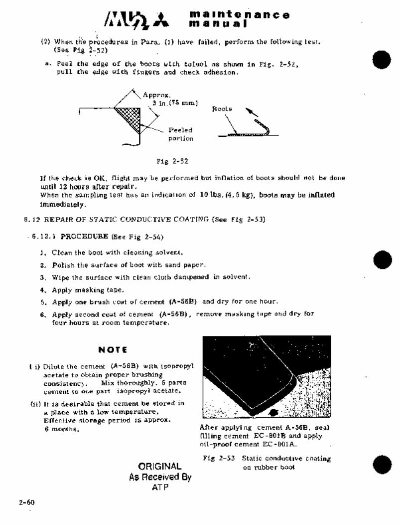
~PO a Il-iri;t is a a a c am a i;B iio a B
~I i.(2) Mfh’eri thb procedures in Para. (1) have faii~d, perform the following test.
(See Pig 2-52)
a, Peel the edge of the hoots with toluoi as shown in Pig. 9-52,pull the edge with fingers and check adhesion.
Approx,3 in.(75 mm)
Boots
Peeled
portion
Pig 2-52
If the check is OK, flight may be performed but inflation of boots should not be done
until 12 hours after repair,When the sampling test has an indication of Id Ibs. (4. i kg), boots may be inflated
immediately
6. 12 REPAIR OF STATIC CONDUCTIVE COATING (See Pig 2-53)
6.12,1 PROCEDURE (See Fig 2-54)
I. Clean the boot with cleaning solvent.
2. Polish the surface of boot with sand paper.
3. Wipe the surface with clean cloth dampened in solvent.
4, Apply masking tape,
5. Apply one brush coat of cement (Pi-56B) and dry for one hour.
6. Apply second coat of cement (A-56B), remove masking tape and dry for
four hours at room temperature,
NOT~
i) Dilute the cement (A-56B) with isopropylacetate to obtain proper brushing :´•i´•
consistencq. Mix thoroughly, 5 parts I~cement to or~e part isopropyl acetate.
(ii) It is desirable that cement be stored in I
a place with a low temperature, :~5i
Effective storage -period is approx.
6 months. After applying cement A-56B, seal
filling cement EC-801B and applyoil-proof cement EC-801A.
Fig 2-53 Static conductive’ coatingORIGINAL on´•rubber boot
As Received ByAT P
2-60

kai is iii P a rii a is h a
ii;il a ~iiU ei~ I
Ceinent EC-801A is applied on this area
0. 12 in. 0.7 in. 0, 12 in,Tape :i (3 mm) (3 mm) 1771’(3 mm)
Tape
~t/
Boot Wing skin Cement´• A 56B
Pie 2-54
6.13 AND REPLACEMENT OF DOOR RUBB~R SEAL
IS rubbeirseal is damaged or´•deteriorated, replace as follows:
6. 13. 1 REQUIRED MATERIAL
(1) ladhesion~ MIL-A-5092 Type II
(for repair) Alon ~Alpha 201 TOA GOSEJ’Co.
(2) Solvent Methylethylketon TT-M-261 or equivalent
(3) Diluent Toluol
(4) Sand´•paper #200-h´• #400
6. 13. 2 REMOVAL OF RUBBER SEAL
(1) Pee! the edge of´•rubber sealoff; using a small amount of Methylethylketoneand applying M1 E. K., pull the seal off slowly. Apply cement remover
(Turco 2822) to cement ´•temaining on airplane, -´•leave it for about
15N and scrape with bamboo or aluminum spatula. Small
amount of cement remaining should be removed with M. E; K.
NOT E
(i) Use rubber gloves.and overalls to’ prevent any
harin.to skih and clothes from nirco-2822.
Special care should be taken to prevent from
gettingthem in eyes or mouth.
(ii) Do not apply cement remover (Turco 2822)to any area.which aoes:not need it. Painted
areas should be protectedwith masking tape.
6.13..3 CEMENTING O;F RUBBER SEAL
(1) Perfdrm sanding:on cementing surface wit~200i-#400sand paper anCI wipe
with´• cloth-darriljened, in Methylethylketone.
(2) idipply one ~h’iri coat.bf cement~tb th~’ dementing surfaces of rubber seal
side aiud airplane side.
2-61

C~-A m a Int a a a.n a arol a a a a I
!9)’ A Cew ;ninutes la~er, attach fubber seal to airplane, taking care to keepdust fre’e.
Necessary time to obtain proper consistency inay differ due to temperatlireand humidity. 3t is 2- 8 minutes at 74"F (23"C) and 60~o humidity.
(4) After setting proper position, press the seal down to the cementing surface
to remove air. Roll the seal if possible.
(5) After cementing, leave it at least 8 hours at 740F (230C). Heat or
water should not be applied on the cementing surface for 72 hours.
(6) Wipe off excess cement with a Methylethylketon or toluene moistened cloth
before drying.
6. 13. 4 REPAIR OF RUBBER SEAL (See Fig ´•2-55)
(1) Preparation
Wipe off the cement remaining on the damaged area with a Methylethylketonor toluene moistened cloth: Take care that Methylethylketon or -toluene
does not sink into the cemented area.
(2) CementingAfter cleaning the damaged area, apply Alon Alpha 201 and immediately
press down the seal. A small amount of Alon Alpha should be used.
Much use of Alon Alpha reduces cementing strength in addition to wastingcement. Since Alon Alpha has a short cementing time, quick action should
be taken.
Cabin door
ADP1069
Sealed surface I I /-sealed
surface
Sealed surfaceClearance
Seal should not come 0~ 08 y 0, 12 in.
out of ddor clearance (2 to 3 mm)
Fig 2-55 ‘Repair of door rubber seal
2-62

9C m all a a a a a a Ca
at mnual
7. ,AIRFRAME AND SKIN
EYlaterial thickness and type of skin used in this airplane are shown in
Fig 2-56.
No IGauge in.(mm)~ I´• Material No I Gauge in.(mm) Material
1 i .016(0;41mm) 2024-T3C 1 17 1’ .05Q--~ .0197 2024-T3C*
(1.27 0. 5 mm
2 i .020(0.51mm) 2024-T3C 1 18 0788 --3.059 7075-T6C a
(2. O ii. 6 mm
3 .025(0. 64 mm) 2024-T3C 1 19 .0;88 --~-.059 7075-T~6C
(2. 0 -1.5 mm
4 i .032(0.81mm) 2024 -T RC 20 .032(0. 81 mm) 6061 -T6C
5 i .0~0(1.02mm) j 2024-r3C 21 j .040(1. 02 mm) 6061-T6
6 050(1. 27 mm) 2024 -T 3C 1 22 .0788 -.059 2024-T3C
(2. 0--1.5mm)7 .0394 .9237 2024 -T 3C 2.3 O 2 5 (0 i 64 mm) 20 24 -T 4 2C
(1.0--0.ii mmj .090 -.032 2024-T3C8 .063 -.032 2024-T3C 24
9;!i.s --o.BImm~I 301(MIL-S-5059)(2. 3--0. 81mm
016 (0. 25 032(0. 81mm) 20 24 -T4 2C
io .o16(0. 41 mm) 347(M1L-S-6721) 26 1 .063 .051 2024-T3C
(1.6 --1.3mm)11 .0197(0. 5 mm) FRP 27 i .020 (0.51 mm) 2024-T42C
12 1 .0296(0.75 mm) PRP 6061-T628 0 25 (0. 64 mm)
13 1 .0394(1.0 mm) FRP29 1 .040 (1. 02 mm) 2024-T42C
14 j .0492(1.25 mm) FRP
30 1 .040 (1. 02 mm) 6961-’16
15, .050(1.27 mm) 6061-T6
31´• .032 (0. 81 mm) 2024-T42C
16 059(1.50 mm) 2024 -T 3C
"denote chemical milling processed parts.
4 24
23 3 ´•4. 12 29 3 3 26_~_ 23 3 3
Fig 2-56´• Skin chart (1/2)
2-(63~6.4
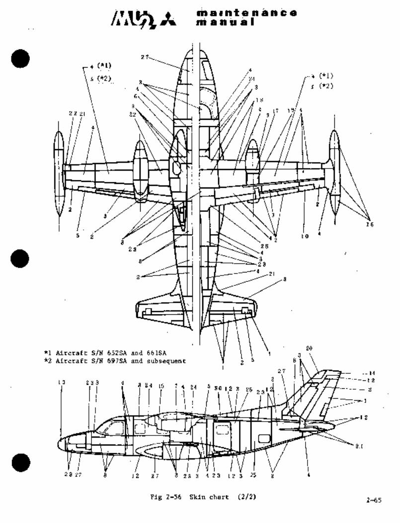
;1 d. ii
m a i a It ~i is in ;en nl a ti a a I
zi
4 ("1)
3 ICliCLL1\ /21 ya (*1)
4v~ JLtl //i 3 s (*2)
618
3. \\\´•14 L7 19/422 21 2 9
3 Il‘h r\ \3
is
52 4
34i 10
2823
4
23
2 3
20*I Aircraft S/N 652SA anh 661SA \Y ‘I ~s*2 Aircraft S/N 697SA and subsequent Y-´•’ i 5 8
2.7 1~ 1!\´• ~F-------143 1 I\ L~T-T-----1213 233 4
8 zp ‘15 -.´•7
4j$ 3P’~ilt 2523
I
12
iJ c..j
3:1
23 27 3 112 27 ’g 23’3 4 23 12 g 25 i 4
Fig: 2-56 Skin chart’ (2/2). 2-65

nl a.l a t a a a a a a
pn a a a a I
8. ACCESS DOOR
Inspection of airframe structures and equipment should be done with necessaryaccess door opened. Main access doors of wing and empennage are shown in
Fig 2-58. Main access doors of fuselage are shown in Fig 2-59.
´•8.1 MAINTENANCE PRACTICE
8.1.1 When removing access doors (panels), care should be taken not to
damage panels, adjacent structure and fasteners. Apply appropriatesealant when required and tighten fasteners to proper torque value.
8.1.2 Engine Nacelle Door Latches
(1) Close the side doors and lock the latches, closing force should be
5 to 15 Ibs., adjust as required.(2) With the side doors closed, close the uppe~ nacelle door andlock the
latch~s, closing force should be 5 to 15 Ibs., adjust as required.
DOOR
D) NOT HOOK 5 TO 15 UIS
aFig 2-57 Nacelle door latch STOPPEA ASSY
M W1LATCH HAWLE
Key to Fig 2-58
No. Name
1 Center wing leading edge upper door
2 Center wing trailing edge upper door
3 Fuel tank access door
4 Fire extinguisher access door
5 Electric and fuel system access door
6 Flap and spoiler mechanism access door
7 Fuel tip tank line access door
8 Trim´•aileron actuator access door
9 Nacelle ddor hook
10 Flapgear box access door
11 Gyro compass flux valve access door
12 Actuator chain access door
13 Elevator trim tab a~tuator access door
14 Fuel filler
15 Accessdoor
16 Fuel system access door
17 Fuel leakage inspection door
18 Trim aileron actuator electric plug access door
19 Outer tank access door
2-66
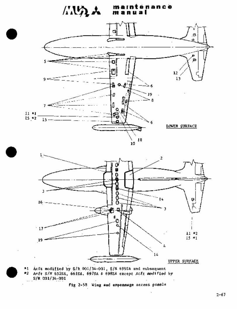
piii ia i rs 9 n n ~e
5 ’"P
13
11 *1
15 _82 15
LOWER SURFACE
1810
16
17
11’*2
15 *119
14
UPPER SURFACE´•
+1 ~icft modified b; SIR 001/34-001., SJN 699SA and:subse~uent*2 Acft S/N 652SA, 661Se, 697SA 698SA except AcS’t modified by
S/R 001/34-001
Pig 2-58 Wing and empennage access panels
2-67

~ii all ii t a a a a a a
manual
20
19
12 18
~3 o o o io
15 16 17
1 3 4 513 14
6 7 8 6 8 9 11
NO. I NAME
1 Nose cone glide slope antenna
2 Electronic compartment door
3 Landing lights (LH~& RH),anti-icer fluid tank CRH)4 Landing gear chain (LH), wiper motor (RH), anti-icer control assy (LH)~5 Communication door (LH)6 Landing gear door control mechanism
7 Cable fairlead
8 Cable
9 Landing gear motor
10 Gearbox d drag strut support11 Landing gear power train
12 Spoiler servo actuator
13 Step mechanism
14 Pulley bracket, control cable
15 Electric electronic equipments, air conditioning system16 Main fuselage-aft~fuselage connectingfitting longeron (upper lower)17 Rudder quadrant18 Actuator chain
19 1 Rudder trim tab actuator
20 Antenna system
Fig 2-59 Fuselage main access panels2-68

~O 1 II
Ptii ir In Udl
9i
(1) of_~iare ~3bB and fiexib~e hbs.
Flilre tuls8 and nexible hose fittings with steel couplirig nut or steel insert
en tube excldded) i"-lbs(kg-cin)505i-(j Al Flexible
O;D( alloy tubeij06i-T6 Al alloy tube
hos8CRES tubel NOTE
1/8 20 30 25 i 45 45 55 i"´• (Mm)(23- 35) (29; 52) (52- 63) ~be
3/16 30 C 40 4~ 55 (52 63) 70 100 90 i 100 Thi ckness(35 46) (81 115 (104 115) *1 0~0491/4 40 65 80 105 (92 121) ‘70 120 ~35 150(46 75) (1. 24)
90 115 (104 132)* (81- 138) (156 173)*2 0. 042
5/16 60 80 80 105 (92 121) 85 180 180 200 (1.07)(69 92) 125~- 175- (144-202) *2 (98 207)) (207 230)1*3 0, 028
3/8 75- 125 125-1?5 (i44-202) (0.71)100 250 270.- 300
(86 144) *4 0.0351115 288 (311 346)1/2 150 c 250’’1’ 135 -180 (156-207)*3 210 420 450 500 (0´•. 89)
~1’3:-´• 288) _(~ 200.- 300 (230-346)*4 1 (242- 484)1 -(518- 576)
400 500 (461-576)
5/8. 1 200-.’350 1 500- 600 (576-691) 1 300- 480 ’700 800
(230 403) (3~46 553) (806 922)3/4 300 500 600 700 (691-806) 500 850 1‘100 1150
(346 5:76) (576 979 (1267 -13251 500 700 1000 1300 (1152-1498) ‘700 115 1200 140
(576 806) (806 1325 (1382 -16131 1/4 600 900 1´•300 1500 (1~98-1728) 1300 145
691 1037) 1498_1670)600- 900 1400- 1700 (1613-1958) 3~0- 1500(691- 1037 1555;1728)´•
(2) Installation torque of uriion to boss
in-lbs (kg- cm)
Tube O. D.I 1/8- 3/161 1/4 5/16 3/8 1/2 5~8 3/4 1 and up
50-.) ´•75-] 80-11100- 100- 200; 360- 390- 600-Al or 75 90 100 130 130 240 400 430 900steel .(58-;1(86-1(9´•2-jl (11.52 1(115- (691--Boss 8’;) 104)1 115)1 150) 150) 276) 461) 495) 1037)
~(3) Installation torque ol-´•oxygen tube
in-lbs(kg- cm
TubeAL ailoy tube: Copper tube
O.D (solder type)
3/16 40-50(46-58)
5/1´•6 100-:125(115-144)
3/8 200-250(230-288),
1/2 300-400(346-461)
2-69

m a at a a a a a a
m.a a a a I
(4) Installation torque of niajor joints and standard installation torque of nuts.
Item Torque Valuein-lbs -cm
Nut Control wheel 1750-1C)i:’,840-1152)Nut Flap stop assembly IBolt Nose wheel assembly 60(69)Bolt Main wheel assembly 220(253)Nut Engine mount (To wing) 12 8(2. 3-9. 2)
Nut- Wing to fuselage c; 25(7 29)Bolt Propeller outer blade clamp 780(899)Screw Propeller inner blade clamp socket 480(55:’1!Screw Propeller counter weight socltet 780(899)Nut Propeller piston edge )860- 1440(991-1659)Valve Tip tank sniffle )300-400(346-461)Bolt Fuel level control valve io 1´•1(11.15 16)Bolt Scavenge pump-rear bearing Tighten to 75 to 80 in-lbs(86
to 92 kg-dm), then loosen and
retightento 50 to 55 in-lbs.
(58 to 63 kg-cm).
Plug Magnetic oil drain 60 70(69 81)
Coupling Bleed air shutoff valve (2´•´•1502-150) 90 110!10´•~ 127)
I Coupling Bleed air tubing in dorsal fin(NAS59 2-32, NAS59 6-32)(900- 1200(1037-1
Coupling Bleed air tubing (24502-200) 1120-140(138-161)Coupling Bleed air tubing in wing trailing edge(NAS592-20 and 1600-900(691-1037)
MAS5S 6- 20)
Coupling Bleed air tubing in nacelle fillet (24502-125) 65 75(75 86)
Coupling- Precooler inlet (24540-200) 30 4.0(35 46)Coupling Refrig.eration unit bypass liue (24540-150) 3b 40(35 46)
Coupling Refrigeration unit bypass valve (69738-150) 145 50(52 58)
2-70

irs’i ai pa t.ie~-h ~i n ci= ei~tn ri n lo B I
Ln;ssi E;iC AT rOi~j I 1
B~olt, Stud arid screw having a tenSile stren~th´• of 125, OdO
psi Y145, 000 pSiBOLT
I~ IEx. AN3, AN173, NIS200j3 serEes bolts, AN502, AN503,S~vnNAS 220 series screws
S%REWShear bolt ~nd screw having a tensile strength of 160, 000
NOMINAL DIA psi ^180, 000 psi
I Ex. NAS1103,NAS1143, NAS1153, NAS 1203 series bolt
NAS 51 7 series screw
Corrosion Resistant steel bolt and scr~w having a tensile
stren-gth of 140, 000 psi or more
(Ex..NAS1´•003 series bolt, NAS560H series screw)When the above bolts, studs and screws are used with
shear nut (AN320, NAS1022 or equivalent)When the: above bolts, studs and screws are used as hingepins together M’ith nuts (NAS679A or MS21042)
Coarsel Fine I a i.n Ib tp m ft- Ib
Y 8--92 8-36. 9- 1 1 7- 9
+10-24~1 910-32 14- 18 1 12-- 16
-20 29- 86 25- 80
-28 35- 46 3 9- 4 0
-!8 56" 66 48- 55
y, -2 4 7 0- 98 1 6 0-- 88
8/8 -16- L 1 0-c~ 180 9 5-- 1 1 0
8/ -24 110-- 180 95- 110’8
_14 65- 180 1 40-- 15.5
/1~-20 810- 860 ~70-- 300
1´• 290 2.8- 8.8 eo-- z42 8 0-- 940 84 0-
1/2 -20 8 4 0-- 470 2 9 0-- 410 3. 3 5 4. 7 26 c~- 81
9/6 -12 3 5 0-- 490 3 0 0-- 4 2 0 8.6 4..8 1 .26 5 86
9/ _Ig) -5 6 0-- 690 4 8 0-- 6 0 O 6 ´•c~ 6.9 1 40-- 60/16
~g -L11 1 499- 620 1 420- 640 4. BS 6. 2 86´•Y 45
5/8 -18 700´•Y 900 1 660-- 780 7. 65 9.0 1 665 65
Pi -io 810- 1100’ 7 0 Oi 950 8. 0 1 0. 9 68 78
1500- 1700 .1 1300--´• 1503 4. 9-17. 8 108--125
7/B .15 0 8-- :2.1 0 0 I 1 3 O 0--: 18 0 0 I 4. a 2.0. 7 I 0 8 1 6 0
~I 7/8 ’14 3800´•-´• 2100 iFjOO-c~ 1800 17: 8‘ 2 0. 7 125 --150
81 1. 2 6 0 O--. a 500 2200- 3000 g 5. 8 3 4. 6 18 8 2 6 0
--1 4 1 2600- 88 00 2200- 8800 1~ 26.8 38. a 188 5 2 7 8
3 8 0 0- .4 8 0 0 8800- 4000 1 8 8. 0 4 6. 0 2 7 5 -c~ 8 8 8
84. 6-48. 4 2505860I/a -12 8500- 4800 8000- 4200
4600- 6800 4000- 6000 b 6. 0 --5 7. 6 B 8 8 a 1 6
17600 1. 5400- 6600 1 6 2. 2 7 6. O 4 60 5 6 601 -12 6 80 0-
2-(71)72

rm a a a aii~ bi Ylal f se ii se a 9r
..1..,:
´•1,;.1
Bdlt;.stud.an~ Screw haviiig a tenbile~ streiigtli d~ 12j, OObi
pst; i45, P~i´•AN563STUD Y%n: A~J3´•, iiN~78, M520073 series bblt; Ai~502,
SCR~W I~As iib ~cred
Sheaii ~bblt aiid fiaviiig a tensile strength ofNOMINAL DIA
i60.000 psih´•18d, i)OO psii~Ex´•. NAS i’ i 3, l\jAS 1 i 4 3 NAS i 1 53 NAS 1 20 3 series balt~,i~AS5i 7 series screitr
O Corro~idn ItlesistBnt Steel bolt and screw having a tensile
Stren~h or140, 000 psi or more
CEx. NAS1003 series bolt, NnS560H series screw)When the above bolts, studs anc.l screws are used with ten
sioA nut (AN 31 0, MS 2104 2, MS 21 04 3 NASG 79A, NASG 79C
NAS102´•1 or equivalent), nut plate or equivalent threaded
machine part
Coarse Fine´• I C i" i Ib ~p .31 ft Ib
’8-82 8-86 1.4- ie 1 12-
~10--24 1F10--92 285 29 1 25
1~ -zs 5.8- stao- 70
-zo a65 68 40- 50
6~_18 ~s-- 105 80~ 90
6/rS 4 1155 1SO 1 0 0- 1 4 0
8/8. -16 1 R5- 215 1 1 6 0-- 1 85
8~´• -24 185- 220 1. 1.60--´• 190
7/i´•s _14 I ´•1 270’2 800 2a5- 255 i 2.8 U 2.9 29- 21
7~, -2 9 ~205 680 4 6 OCI 5 0 O 1 5´• 1 CC. 5´• a I 81CI 42
?/2 1 3 1 4 8 05´• 560 i 4 0 0-- 480 4. 6 5. 6 8 8- Q 0
-201 5 6 9- 800 4 8 0- 6 90 5 5 8. 0 49- 58/2
580-- B10 500- 7 00 5. 8 8. 0 42- 58
9~6-18 930-- 1200 809- 1000 9. 8~ 11.61 67- 88~
5 810- 1000 700- 900 8.0- 10:4( 58- 76
5~8 -18 18:00-- 1600 1100-- 1800 1´• 12.7 14.9 9 2--1 9 8
-Io 1409- 1800 i 1150- 1600 1 a. a- ~s.´•e 96--188
8~ -1 200-- 2900 j. 2800- 2500 26.6-c~ 2ii.81 192-208
7/8 _ 9 1 2 6 0 0´•-. 8 5 00 2290- 8000 25.8´•" 84.6 188-260
7~ --141 290 n-- sso 3 2500- 8000 28. 8 N -84. 8( 208-250
5’000 4-2. 6" 575 308´•14]6
1 .-1.41 4 900´•- 6800- 1 970~- 5500 48.6 68.81 8 0 8~4 6 0
1~8 -.8 6 a 0 o- 7.6 0 0 5 6 0 0- :-6 6:~0 0 6 a. 6 7 4. 7 4 60-5 4 0
11/8 -12 5.8 0 0; 8 -1 0 0. 5 0 b 0". ´•7 0 0 0 6 7.’4~ 8 0. 2 4 1 6-5 a 0
7 6 0 0~ 9 2 a 0 6’50.0- 8000 74. 7 h 92.6 1 5 4 0--6 7 0
1~ -1 i I .1 a4:oo;i 2 7 06 1 9 0 0 0--1 1 9 0 0´• 1 OL 7 N 1 2C
i 7 I,ON9 2 0
2-73

m B i.~ i a a a ri a a
on a li~ iu a I
LASSIFICATION I II
BOLT O Bolt, stud and screw having a tensile strength of
STUD 140, 000 psi´•vl60, 000 psiSCREW
NOMINAL DiATension nut MS21042 or equivalent
Coarse Fine 4 a in Ib m it Ib
t a-80 A-as Is-- 20 1441 17
+10-24 +lo -3 z 27~ 86 128- 30
1/4 -20 52- 68 1 4 5- 59
-28 69- 92 60- 80
6/;6 -18 93- 136 85- 117
;i~6 -2 4 1~ 140- 200 1 2 0-- 172
a/A -Is 200- 250 1 7 3- 217
8/8 -24 200~ 810 178-- 271
7/16 -14 280- 890 24 5- 842 2. 8- 4. 0 20- 29
~B -20 5605 720 I 7 5- 628 5. 5- 7. 2 40- 52
.510-- 7’8 0 44 0-- 686 1 5. 1--7
9 37- 58
?i -20 6 8 0- 970 5 8 C- 840 6. 8-9
7 49- 70
9/;6 -IZ 690-- 980 1 600U 845 6. 9- 9. 7 50-- 70
B~s -18 1100-´•1400 900-- 1220 1 10.1-- 14.L 1 75- 102
5/8 -11 920- 1800 800- 1125 9.3- 13.0 67- 91
1100-- 2600 1200- 1730 13.8- 19.9 100- 144
8/, -10 1600-- 2200 1380- 1925 18.9- 22.L 115- 160
8~ -16 1 28 00-- 4 0 00 2400- 9600 27 7- 4 0. 4 200- 292
7/8 9 8000´•14100 2600- 8570 299- 41.2 216-- 298
7/8 -14 3200- 5400 2750- 4650 31.7- 58.6 229--888
1 A L000-- 6800 4850-- 5920 6a´•0-- 68.4 a62- 495
-14 5800- 8400 4600- 7250 53.1- 83.6 984--605
Il/g 8 6 9 a 0 --1 0 0 0 0 6000- 8650 69.1- 99.5 500- 720
11~ -ie 6 9 0 0 ~I 1 8 0 0 6 0 0 0-- I 0 2 5 0 6 9. 1--1 1 a. 2 500- 855-
11/4 A 8 I 0 0--1 2 7 a 0 7 2 5 0-- I 1. a 0 a 8 3. 6--1 2 6. 6. 605- 916
11~ -1 2 1 1 5 0 0--1 9 8 0 0 I 0 0 O 01 1 6 7 5 0 1 1 5. 2-1 9 2. 9 8 a 8--1 9 9 5
2-74

.m a u:n 8:n ~L1 id~i a iii ii.~in O
ill
O Bolt; ~tud a~d S~i´•eC havin$ a tensile strength biBOLT
160 6b psi aiiaS~IjLi
CEx. ~iS20604YMSibb24, MSXiiS~j Serie~bdlt)SCEiE~ii
Wh~en the Biii’ove: boitt~; StuidS and Sereis are withrjoMI~JAij DIAt~lisioh n’uf; l\ii~.21’04i br´• eqLiivalent, fi~B, IIT20, 4iF’W
Coara.e...:l.:,Fink ~4 ci i ri i Ib I tp i. f t .-lb
r;ssl´•~ 8-861 is; ef lb- Ib
~IOis2 29-; 40 26-L 86
i j;B 50i 882 58-
-28 i. 81" ios 70- 90
i 1 105-- 170 90- 144
6~s _24 166-- 240 L 4 0- 208
8~ -18 220- 290 185-- 248
220~ ~00 190U 551/R
7~ ;.1 4 800- 500 255" ´•q28 2. 9´•-- -5. 0 I 21-- 86
7~, db 580-. 87´•01 505-. 718 1. 5.8- 8.7 1 42- 88
~-ls 560- 9)0 80-- 792 1 5. 5- 9. 1 40- 66
~-20 800- 12.00 1 890- 990 8.0- 11.6 68- 88
810-- 1200´•1 700~9901 5.0- 11.6 68- 88
9/;6 -18 1200- 1700 1 100´•0-- 1410 1 ´•1 1. 5- 16. 6 83-- 120I
6/8 -1 1 I I 1’1 0 02-~ i 6 CO Ii .8 0 OC1 1:9 5 0 I 0´• 4CC, 1 5´• 5 1 75U 112
6~ -18 1800~- 2600 .1800-- 2160 14, B- 24. g 108-- LBO
8~_1 0 I 1 1900- 26001. 1600- 2250 1 8. 4- 2 6. 0 188- 188
8~ ~_ 1 8 2 90 0" 6 2 00 1 2 a 0 o-- 4 5 5 0 2 8. 8-- 6 1. 8 zo8-- 876
7/9´• _, 9 I I .8 5 0 0- 1 8 0 0 1 8 0 0 0- 4 L 4 0 3 4. 6- 4 7. 7 2´•~ 0-- 8 4 6
7~_14 8600- 7800 8 00 OIy 6 8 O O I. 3 4. 6~ 72
8 1 2501. 525
1 8 1 ’1 5 8 0 0- 78 00 I 6 O O 0;. 6 8 4 0 5 7. 6- 7 8. 8 416~- 570
1 -14 6400-104.001 6600-- 9000 6 3. 6-10 8. 7 1 4 6 0-- 7 5 0
7 6 0 0--1 2 6 0 0 .1 6:6 0 0´•-10 8 0 0 1 74,7-124.4 .510- 900
1 _1 2 .8 1 0 Ou1.6 8 9 0 i 7000-18500 8 2i1 6 4. 8 5 8 0--: 1 2 0
I .920 0-18 loo I 800 o-lo 90 92.-1--160.11. 66 6--1160
12700---25900) 11000-22500 1; 1.27. 2N259. 9 1 9 2 0-1 8 B 0
2-75
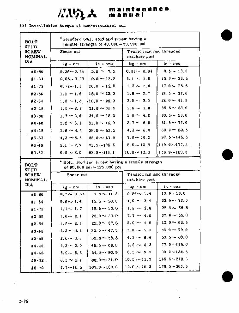
~m a Int a ~n a a a a
m a a a at
(5) Instaliation torque of non-structural nut
Standard bolt, stud and screw having a
BOLTtensile strength of 40, 000h 60, 000 P6i
STUD
SCREW 1 Shear nut Tension nut and threade’d
NOMINAL ’I I machine partDIA
kg-cm in -ozs I kg -cm I in -ozs
~0-80 0. 36- 0. 54 5. 0" 7.5 0.61h´• 0.94 8. 5´•v 13.0
81-64 O. 65-´•0. 97 9.0 13; 5 1 1.1 ´•v 1.6 15. O cy 22. 5
#1-72 .1 0. 72-1. 1 10. 0-15. O 1.2~ 1.8 17. O´•v 25.5
#2-56 1.1 ´•v 1.6 15. O 22. O 1.8 h´• 2. 7 24.5^´• 37.0
#2-64 1.2 N1.8 16. O 25; O 2. O N 3. 0 28. ON 41. 5
#3-48 1. 5 N2. 3 21.0 h´• 31. 5 2.6 N 3.8 1 35. 5´•v 53. O
#3-56 1 1.7´•~ 2. 6 124. O N 35. 5 2. 8 4. 2 39. 5^´• 59. O
#4-40 1 2. 2 ´•V 3. 3 31.0 y 46. O 3. 7 5. 5 51. 5N 77. O
#4-48 2; 6 3. 9 36. O ´•v 53. 5 4.3 N 6.4 60. 0~ 89. 5
#6-32 4. 2 rv 6. 3 58. O h, 87. 5 7. O 10. 5 97. 5~145. 5
#6_40 5. 1 N 7. 7 71. ~´•v106. 5 8. 6N 12. 8 119. 0^´•177. 5
#8-32 6,0 N 8. O 83. 3 --111. 1 1O. O 13. O 138. 9~180. 6
Bolt, stud and screw having a tensile strengthBOLT
’of 90, 000 psi~125, 000 psiSTUD
SCREW Shear nut Tension nut and threaded
NOMINAL machine partDI[A
kg-cm ~I in -ozs kg-cm in -ozs
#0-80 0. 5 h´• 0. 83 7. 5 cv 11. 5 0.94h, 1.4 13. 0~19. O
#1-64 0. 9~1.4 13. 5^´• 20. 0 1.6 2.4´• 22. 5rv 33. 5
#1-72 l.lN 1.7 15.5N23.0 1.8 h´• 2.8 25.5h´•38.5
#2-56 1.6N 2.4 22. Oh´• 33.0 2. 7 4.0 37. O ´•v 55.0
#2-64 1.8^´• 2. 7 25. ON 37. 5 1 3´•0 rV 4.5 42´•ON 62. 5
#3-48 2.3- 3.4 32. ON 47. 5 3. 8 N 5. 7 53. O N 79.0
#3-56 2.6- 3.9 1 35.5cu 53.5~1 4.3 N 6.4 59.5^´• 89.0
#4-40 3.3N 5.0 .1 46.5h, 69.0 5. 5 rv 8. 3´• 77. 0´•--115. O
#4-48 3.9^´• 5.8 54. ON 80,5 .1 6´• 5 IV 9~ 7 90. O ’V 134. 5
#6-32 I 6. 3h´•9. 4 88; 0´•--131.0 10. 5 ´•v 15. 7 146. 5-218. 5
#s-40 7.´•7~11.5 107. ON160. O 12. 9 ´•v 19. 2 178. 5--266..5
2-76

II iitiitn iii iC ri~ I
Ib.
At iihe o’l ai~’d. far:1.1´•~ Ailthe 09 iLindP~iiB1:
changes aiid 8~tei- d’eliveirj;~ ~re the
of ’t~ie airpla~e b~.tecofded’in the aiircraft log book,
To Iba~ing maintain a record of
ail weight ana balinc$ in the "mpty ~eight and,Balance Record"’chart
in sectibn APjD the PILb~ OPEkGTINO MANijAL.
to, 2 MEASUREMENT, CAiiCijLAT~ON AND CHECK.dF WEI’GHT ~3D BALA~CE
All instructibn; for me’a$urement calculatidh of
ttie ~jeiSht bPl~liCe bf th"~. is in the "WEI~HT AND BALAN~E"
se~tion bf ti~e ´•P MANtTAf,;´•
10,3: EQUIPMENT NA~S, WEIC~HTS AND C~NTEa 09
Basic equi~ment, their weights and center ofgravity~ds locdted in the
"WEIcHT AMD section of the PILbT’OPERATI~G MANUAT~.
i ’i´• :i:; i
2;77

maintenancenl a a a a I
11. CHAIN WEAR LIMLTS
11.1 VISUAL INSPECTION
(1) Gain access to chain by removing access panels, covers, etc.
(2) Carefully inspect the chain for dirt, rust’and corrosion.
(3) Should the chain require cleaning, remove from aircraft and
use a petroleum solvent for cleaning.
NOT E
Under no circumstances should
rust or corrosion be removed
with an acid because it may
embrittle and crack the links.
(4) If after cleaning there is evidence of remaining rust or
corrosion, also should there be pitted areas, especially on
the rollers, the chain should be replaced.(5) Visually inspect all links for ui~iform wear of the pin, roller
and link.
(6) Re-install chain if removed.
11.2 MEASUREMENT OF CHAIN WEAR
11.2.1 Required tools
(1) Pull scale O to 20 Ibs (O to 10 kgs)(2) Linear scale
11.2.2 ´•Procedures
(1) Remove chain ~from aircraft.
(2) Attach one end of the chain to a pull scale while
securing the other chain end (or approximately 12
to 18 in. (305 to 457 mm) from the pull scale end)to a stationary fixture (such as hook through a
link attached to a bench vise).(3) Apply 18T 0.5 lbs´•(8.20~0.24 kgs) pull on chain.
(4) Measure lengthof any 10 links of chain. Should the
length "L" exceed the weaz: limit for chain listed,
replace it with a new one.
CHAIN. LOCATION "L" MAX WEAR LIMIT
Landing gear 3.806 in (96.6-7 mm)Spoiler control
Rudder trim2.538 in (64.47 mm)
Elevator trim
(5) Re-Install chain.
2-78

c~nmaintenancem a a a a I
12. NONDESTRUCTIVE INSPECTION
12.1 X-RAY INSPECTION
12.1.1 GENERAL
(1) Radiographic inspection is a nondestructive test method used for
the inspection for-airframe structure inaccessible and internal
details of the parts. The inspection is accomplished by passingthe X-ray beam through the part or assembly to expose a
radiographic film in accordance with MIL-STD-453.
(2) This section shows a couple examplesof radiographic inspectionprocedures as guidelines for the´•technitally trained persons who
are unfamiliar with MU-2 airplanes. Therefore, it is necessary to
establish the appropriate exposure conditions of the equipmentand film used.
12.1.2 APPLICABLE DOCUMENTS
The following documents will be referred to when conducting X-rayinspection.
MIL-STD-410 "Nondestructive Testing Personnel Qualification and
Certification
MIL-STD-453 "Inspection, Radiographic"
NBS Handbook 89 "Methods of Evaluating Radiological Equipmentand Material"
12.1.3 SAFETY
The use of X-rays in nondestructive inspection presents a
potential hazard to operating and adjacent personnel, unless all
safety precautions and protective requirements are observed. An
excellent source of information on radiation protection can be
found in National Bureau of Standards Handbook 93, "SafetyStandard for Non-Medical X-Ray and Sealed Gamma Ray Source"
12.1.4 ABBREVIATION
(1) KVtkilovoltage
(2) MA’Milliampere
(3) SFDxSource toFilm Distance
12-24-86 2-79

c~nmaintenancemdnua(
12.1.5 PROCEDURE
(1) The surface of the part to beradiographed shall be clean. If
cleaning is required, refer to the Maintenance Manual for propercleaning materials.
(2) The direction of the central beam of radiation shall be, wheneverpossible, perpendicular to the surface of the film.
(3) Place the film as close to the surface of the material under test
as practicable.
(4) Keep the distance from the X-ray source to the film (focaldistance) great enough to produce a sharp image on the film.
NOTE
Settings specified in individual radiographprocedures in this section were established to
provide quality radiographs. It may be necessary to
vary the MA, time and KV settings due to differeces
in equipment, film and method of processing in order
to achieve the contrast, sesitivity and densityspecified. Therefore, the MA, KV and time settingsshould be construed as guidelines. X-ray equipmentis considered acceptable provided it produces the
quality radiographs specified for procedurescontained in this manual.
(5) Use as low a potential (Kilo Voltage), as high a current
(milliamperage) as is practicable to obtain proper sensitivity,contrast and density.
(6) Optimum densities are given for each inspection techniquecontained in this section; densities 1.0 to 2.0 are appropriatefor the radiographic examination of this airplane.
(7) Exercise care in handling and storing undeveloped radiographicfilm to prevent the creation of blemishes which might interfere
with interpretation of radiographs.
12.1.6 PERSONNEL QUALIFICATION
Personnel preparing parts, setting up or conducting the test
shall be qualified MIL-STD-410, level I or higher. Personnel
evaluating radiographs shall be qualified per MIL-STD-410, Level
II or III.
2-80 12-24-86

c,r~z. Itmi a´• iln t: ena.n~ a-a
.I. m a n- a. a I:
12.1.7 EXAMPLES, TEST EQUIPMENT
The listed X-ray unit was´•employed (unless otherwise indicated in
the specific inspection technique). When substitute equipment is´•
used, it may be necessary to make appropriate adjustments to theestablished techniques.
NOTE
The use of RADIOATIVE ISOTOPES (Gamma Ray) for
radiographic inspections contained in this manual is
Prohibited.
(1) COMPONENT’ TO BE INSPECTED:
The following components are to be inspected by X-ray inspectionas required in Maintenance Requirement.
Component Material Total Part thickness
Horizontal Stab. Front Spar Aluminum O.SO"(root) to 0.17"(’tip)Horizontal Stab. Rear Spar Aluminum 0.30"(root) to 0.13"(tip)
Flap control Sys. Ui~iversal Steel 0.24" for direction A
Joint 0.40" for direction B
(NOTE)
NOTE Thickness by direction
0.12"
0.12"0´•40"
12-24-86 2-81

nl a i a t a a a a a a
m a a a a
(2) RADIOGRAPHIC DATA
The following table represents the sample data which were used duringactual radiographical inspection practice on several experiences of
MU-2
Therefore, specific figures or conditions herein are not to be
considered as requirements for this radiographical inspection but to be
utilized as a guide for a person who is engaging this inspection.
Data herein will vary from equipment to equipment and frcnn condition to
condition at the site where inspection is performed. All necessary
requirements should be established by the qualified person and
conformed to the requirements of MIL-STD-453.
Rigaku, Radioflex
Equipment Andrex
100 GSB
Inspection Company NDE-AID, Inc.(Fortworth, Tx) MHI (Japan)
Component H.Stab. Universal Joint H.Stab.
"ON" or "OFF" of aircraft OFF OFF OFF
KV 100 150 65 70
Ma 4 1 4 5
Time 2 min 30 sec 6 min 1 min
SF Distance 46" 24" 20"
SP Distance contact contact contact
Angle 0" 00 0"
Filter NO I NO I NO
Film Type NDT55 NDT55 KODAK M
Film Size 7" X 17" 7" X 17" 7"X 17"
or smaller
Lead Screens Front No Front .005" Front No
Rear .010" Rear .010" Rear .010"
Density 1.0 to 3.0 1.0 to 3.0 1.0 to 3.0
Penetrameter As Required per MIL-STD-453
2-82 7-1-87

c,r~53 It m a i a t e~ a a a c a
m a n.u a I
TEMPORARY REVISION N0.2-2This Temporary Revision No. 2-2 is applicable to the following Maintenance
Manuals
MODEL NO. REPORTNO. PAGE
MU-2B-25/-261-26A MR-0215 2-80 thru 2-84
MU-2B-40 MR-0333 2-80 thru 2-84
MU-2B-351-36A MR-0218 2-83 thru 2-87
MU-2B-60 MR-0336 2-83 thru 2-87
Insert facing the page indicated above for the applicable Maintenance Manual.
Retain this Temporary Revision until such time as a permanent revision on this
subjectis issued.
REASON To change Fluorecent Liquid Penetrant and Magnetic Particle
inspection.
CHANGE Paragraph 12.2 and 12.3 as follows.
12.2 FLUORESCENT LIQUID-PENETRANT INSPECTION
12.2.1 GENERAL
(1) Fluorescent Liquid-Penetrant Inspection is a nondestructive method for finding,small
cracks or other discontinuities that occur on the surface of a part or assembly which
may not be evident by normal visual inspection.
This inspection is conducted by applying a liquid which penetrates into surface defects.
The ekcess penetrant liquid is wiped off and a developer is applied to draw the
penetrant from the surface crack or discontinuities. Visual Indications are observed by
the fluorescence of the penetrant under ultra violet (black) light. The penetrant method
of inspection requires that the surface in the inspection area be thoroughly clean and
free of paint.
(2) This section provides guidelines forFluorescent Liquid-Penetrant inspectionsby
technically trained persons.
TEMPbRARY REVISION NO. 2-2
Page 113
MU-2B-25/-26/-26A, -35/-36A, -40, -60 Sep. 27 12004

m a i.n f e~n a a c a
mdnwal
TEMPORARY REVISION N0.212-‘3
12.2.2 APPLICABLE DOCUMENTS
The following documents will be referred to when conducting penetrant inspection.
(1) NAS 410 "NAS Certification Qualification of Nondestructive Test Personnel"
(2) ASTM E 1417 :"Standard Practice for Liquid Penetrant Examination"
(3) SAE AMS 2644 "lnspection Material, Penetrant"
12.2.3 PROCEDURE
The fluorecent liquid-penetrant inspection should be conducted in accordance with ASTM E
1417 Latest revision.
12.2.4 PERSONNEL QUALIFICATION
Personnel preparing parts, setting up or conducting the inspection and evaluating
its results shall be qualified per NAS 410.
12.3 MAGNETIC-PARTICLE INSPECTION
12.3.1 GENERAL j
(1) Magnetic-Particle inspection is a method for locating surface and subsurface
discontinuities in ferromagnetic materials material capable of being magnetized);
consequently, nonferromagnetic materials (such as aluminum alloys, magnesium all~s,
copper alloys, lead, nickel base alloys and many stainless steel alloys) can not be
inspected by this method. Magnetic discontinuities not lying parallel to the magnetic
field will cause a "leakage field" to be formed at and above the surface of the part. The
presence of the leakage field is detected by pouring small ferromagnetic particles over
the surface of the part. Some of these particles are magnetically gathered and held by
the leakage field to form an outline indicating the location, size shape and extent of the
discontinuity.
WARN ING
Improper operation of magnetic particle inspection
equipment because of faulty equipment or by untrained
persons can jeopardize the airworthiness of parts being
inspected. Minute electrical burns caused during
inspection by improper operation of the test equipment
can result in eventual failure of the part.
TEMPOkARY REVISION NO. 2-2
Page 2 3
MU-28-25/-26/-26A, -35/-36A, -40, -60 Sep. 27/2004

C~glt m a i.n t p~n a a c a
ma’ nual
TEMPOBARY REVISION N0.2-2
(2) This section shows some examples of magnetic particle inspection procedures as
guidelines for technically trained persons.
12.3.2 APPLICABLE DOCUMENTS
The following documents will be referred to when conducting Magnetic Particle Inspection.
NAS 410 "NAS Ceitification g Qualification of Nondestructive Test Personnel"
ASTM E 1444 :"Standard Practice for Magnetic Particle Examination"
12.3.3 PROCEDURE
The magnetic particle inspection shall be conducted in accordance with ASTM E 1444
latest revision.
12.3.4 PERSONNEL QUALIFICATION
Personnel preparing parts, setting up or conducting the inspection and evaluating its
results shall be qualified per NAS 410.
TEMP6RARY REVISION NO. 2-2
Page 3 1 3
MU-2B-25/-26/-26A, -35/-36A, -40, -60 Sep. 27/2004

maintenancemanual
12.2 FLUORESCENT LIQUID PENETRANT INSPECTION
12.2.1 GENERAL
(1) Fluorescent Liquid-Penetrant Inspection is a nondestructive methodfor finding small cracks or other discontinuities that are open to
the surface which may not be evident by normal visual inspection.Fluorescent Liquid-Penetrant Inspection can be used on airframe
parts and assembl ies accessible for its appl ication This
inspection is conducted by applying a liquid which penetrates into
surface defects. Excess penetrant liquid is wiped off and optimumdeveloper applied to draw the penetrant from the surface defects so
that visual indications are obtained brilliantly by fluorescence of
the penetrant under ultra violet (black) light. The penetrantmethod of inspection requires that the surface in the inspectionarea be thoroughly clean and free of paint.
(2) This section shows an example of Fluorescent Liquid-Penetrantinspection procedures as guidelines for the technically trained
persons
12.2.2 APPLICABLE DOCUMENTS
The following documents will be referred to when conducting penetrantinspection.
(1) MIL-STD-410 "Nondestructive Testing Personnel Qualification and
Certification"
(2) MIL-STD-6866 "Inspection, Liquid Penetrant"
(3) MIL-I-25135 "Inspection Materials, Penetrant"
12.2.3 PROCEDURE
(1) SURFACE PREPARATION
a. All surfaces of a work piece must be thoroughly cleaned by suitablechemical method free from any dirt, grease, oil, paint or any
contaminants which would mask or close a defect open to surface, and
must be water rinsed. No mechanical removing method should be
applied since it would tend to mask defects. The surface should be
completely dried before applying the liquid-penetrant.b. The 1 iquid-penetrant and area to be inspected shall have a
temperature of 60 OF (15 OC) minimum to 130 OF (54 OC) maximum.
(2) PENETRATION
Afterthe work piece has been cleaned, liquid penetrant is applied byaerosol spray or brush to form a film of penetrant over the surfacebeing inspected. This film should remain on the area for a minimum of
30 minutes to allow maximum penetration of the penetrant into any
surface openings that are present. The entire surface of the partinspected shall be maintained in the fluid wet condition until the
penetrant has sufficiently penetrated into the defect interior.
NOTE: Please seeii~TEMPORARy3-20-92REVISION 2-83
C~- thal revises fhis page.

maintenancemanual
(3) REMOVAL OF EXCESS PENETRANT
Optimum removal of the excess penetrant is accomplished by wiping off
as much of the penetrant as possible with a paper towel or a lint-free
cloth, then wipe off the remaining penetrant with a clean cloth
slightly dampened with the penetrant system cleaner and finally, with
a dry paper towel or clean cloth so that the liquid-penetrant into thedefect interior is left remaining as much as possible.
NOTE
The washing method such as flushing over the
inspected surface shall be avoided since thiswill flush the penetrant from shallow defects.
(4) DEVELOPMENT
The developing agent is applied by aerosol spray to form a film over
the surface being inspected. The developer acts as a blotter to assist
the natural seepages of the penetrant out of any surface openings andto spread it at the edges to greatly magnify the apparent width of thecrack. The developer also provides a uniform background to assist
interpretation. Caution should be used in the application of the
developer to provide the optimum coating thicla~ess. If the coating istoo thinly applied the penetrant will not be spread and a crack or
other discontinuity will not be as easily detected, if the developercoating is thickly applied the penetrant might not bleed through the
coating.(5) INSPECTIONAfter being sufficiently developed, the surface is visually examinedfor indications of penetrant bleeding from surface openings. Thisexamination must be performed under suitably darkened conditions forthe penetrant to fluoresce during exposure to ultraviolet (black) lightwhich meets the following minimum requirements (1) 3200 to 4000
angstrom wave length (2) over 1000 iuw/cm2 at 15 inches (38 cm) from thesurface to be inspected (3) darkness of under 1.5 foot-candle in the
inspection area.
NOTE
Care should be taken not to leave it for too
long as the penetrant may spread excessivelyresulting in misjudgement.
NOTE: see the 1‘;TEIWPOHARY
REVISION
that revises this page. I)2-84 3-20-92

maintenancemanual
(6) POST INSPECTION CLEANING
After completion of the fluorescent liquid penetrant inspection, the
inspection areas are to be thoroughly cleaned by suitable solvent or
water rinsed to remove the developer coating and ~nv remaining traces
of penetrant. Then, the exposed area shall be painted per the
appropriate Maintenance Manual or Structural Repair Manual.
NOTE
All components of the penetrant inspectionsystem must be from the same manufacturer and
be designed to be used together. For instance,it is not permissible to use a penetrant from
one manufacturer and a cleaner/remover fromanother manufacturer to inspect the same
work piece.
12.2.4 PERSONNEL QUALIFICATION
Personnel preparing parts, setting up or conducting the inspection and
evaluating of its results shall be qualified per MIL-STD-410.
12.3 MAGNETIC-PARTICLE INSPECTION
12.3.1~ENERAL
(1) Magnetic-Particle inspection is a method for locating surface and
subsurface discontinuities in ferromagnetic materials (i.e. material
capable of being magnetized) consequently, nonferromagneticmaterials (such as aluminum alloys, magnesium alloys, copper alloys,lead, nickel base alloys and many stainless steel alloys) can not be
inspected by this method. Magnetic discontinuities lying ina
direction generally transverse to the direction of the magneticfield of the part magnetized for the test will cause a leakage field
to be formed at and above the surface of the part. The presence of
the leakage field denoting the discontinuity is detected by the use
of finely divided ferromagnetic particles over the surface of the
part. Some of the particles are magnetically gathered and held bythe leakage field to form an outline indicating the location, size,
shape and extent of the discontinuity.
NOTE: Please see the
TEMPORARYREws~onr
that revises this page.
3-20-92 2-85

mainte a. ance
manual
I W~.NING)WARNING
Improper operation of magnetic particle inspectionequipment because of faulty equipment or byuntrained persons can jeopardize the airworthinessof parts, being inspected. Minute electrical burnscaused during inspection by improper operation ofthe test equipment can result in eventual failureof the part.
(2) This section shows same examples of magnetic particle inspectionprocedures as guidelines for the technically trained persons.
12.3.2 APPLICABLE DOCUMENTS
The following documents will be referred to when conducting MagneticParticle Inspection.
MIL-STD-410 "Nondestructive Testing Personnel Qualification andCertification"
MIL-STD-1949 "Inspection, Magnetic Particle"
12.3.3 PROCEDURE
(1) SURFACE PREPARATION
All foreign matters such as grease, paint, scale, and other matter thatwill impair the normal distribution of the magnetic particle, electro
magnetic property, and identification, shall be removed from thesurface of the item to be inspected.
(2) MAGNETIZATIONThe inspection of both the circular magnetization and the longitudinalmagnetization must be performed.
NOTE
a. In the magnetization of items to be
inspected, it must be performed with
sufficient care not to have any current
burningb. The electric current flow time will be 1j2
to 1 second X more than 2 times.
NOTE: Please see the
REVISIONTEMPORARY
that revises this page.
2-86 3-20-92
maintenanceman ual
(3) INSPECTION
a. Unless otherwise specified, fundamentally, the inspection is
performed by the direct current wet type continuous method and thefluorescent property magnetic particle inspection.
b. In the fluorescent magnetic particle inspection, the ultraviolet
(black) light (which is 3200 to 4000 angstrom wave length) intensityillumination on the surface of the item inspected shall be more than
1000 Lrw/cm 2 Also, this examination must be performed under
suitably darkened conditions that are under 2.0 foot-candle (20 lux)in the inspection area.
(4) DEMAGNETIZATION
The inspected items shall all go through the demagnetizer and have a
complete demagnetization performed. If necessary, the confirmation of
the result of the demagnetization shall be made with an adequatedemagnetization meter. (field indicator etc.)
(5) POST INSPECTION CLEANINGAfter the completion of the inspection and demagnetization, all partsshall be sufficiently cleaned with proper cleaning solvent.
NOTE
Furthermore, the´•plug, mask, etc., used for
protection purposes shall be removed after the
cleaning.
12.3.4 PERSONNEL QUALIFICATION
Personnel preparing parts, setting up or conducting the inspection and
evaluating its results shall be qualified per MIL-STD-I10.
E~,REV/SION
’I that revises this page.
3-20-92 2-87

CHAPTER
Al RFRANI E

malntenan ce
manual
CHAPTEIZ’ III
AIRFRAME
CONTENTS
i. GENERAL 3- 1
2. WING 3- 1
2.1 GENERAL DESCRIPTION 3- 1
2.2 REMOVAL AND INSTALLATIONOF WING 3- 2
2.3 REMOVAL AND INSTALLATION OF OUTER WING 3- 6
2.4 REMOVAL AND INSTALLATION OF WING LEADING EDGE 3- 7
3. EMPENNAGE 3- 8
3.1 GENERAL DESCRIPTION 3- 8
3.2 REMOVAL AND INSTALLATION OF EMPENNAGE 3- 8
3.3 BALANCING OF ELEVATOR AND RUDDER 3-10-1
4. FUSELAGE 3-10-1
4.1 GENERAL DESCRIPTION 3-10-1
4.2 NOSE CONE 3-10-2
4.3 ELECTRONICS COMPARTMENT DOOR 3-11
4.4 ENTRANCE.DOOR ...................i.............;.............. 3-11
4.5 EMERGENCI EXIT DOOR 3-15
4.6 NOSE LANDING GEAR DOOR 3-17
4.7 MAIN LANDING GEAR FORWARD DOOR 3-18
4.8 MAIN LANDING GEAR AFT DOOR 3-18
4.9 STEP ASSEMBLY............I
3-19
4.10 CABIN FLOOR 3-20
4.11 AFT FUSELAGE 3-21
5. WINDSHIELD AND CABIN WINDOW 3-24
5.1 GENERAL DESCRIPTION 3-24
5.2 REMOVAL AND INSTALLATION OF WINSHIELD 3-24
5.3 REMOVAL AND INSTALLATION OF CABIN WINDOW 3-26
3-31-90 3-i

c~sAmaintenancemanual
a 5.4 WINDSHIELD AND CABIN WINDOW GLASS 3-21
6. CENTER PEDESTAL.........................................´•1......
3-29
6.1 GENERAL DESCRIPTION 3-29
6.2 REMOVAL AND INSTALLATION 3-30
7. STATIC DISCHARGER 3-31(32)
3-ii 8-1-91

nl a Int a a a a a a
Im a a a a I
aThe aircraft’s structure is divided into three major components:
Wing, fuselage, and empennage. The wing, being of an all-metal, canti-
lever, integral construction, is attached to the upper fuselage by7075-T6 extrusion frame fittings with four bolts at F. STA4850 and
F. STA5605. The wing’s major components are: wing proper, flap,spoiler, and aileron trim tab. The engines are installed on the leadingedges of both wings at W. STA2250, and the tip tanks are installed
at the wing tips.
The fuselage consists of F. STA -170 to 8895 and the aft fuselageF. STA8895 to 10670, connected at F. STA8895 by four bolts. The cockpitand cabin, between F. STA1080 and F. STA8035, can be pressurized to
5.0(*1), 6.0 psi (*2) of the maximum differential pressure. The detach-
able nose cone under which the radar antenna is installed is forward of
F. STA 180, is a honeycomb sandwich constructed radome. The forward
electronics compartment is located in the upper section between F. STA
180´•c~ 1080 and the nose landing gear, with its related mechanical
components and landing light is located directly beneath it. The
cockpit is situated between F. STA 2130 and F. STA 2690, the cabin
between F. STA 2690 and F. STA 7845.
On the left hand side of the fuselage, between F. STA6495 and F. STA7250,is the entrance door, and on the right hand side, between F. STA4850 and
1) F. STA5605, is the emergency door, respectively.
The main landing gear forward and aft doors are located at the side of
bulge between F. STA4265 and F. STA5830. Air conditioning system,
radio, and batteries are installed between F. STA8035 and F. STA8895.
2. WING
2.1 GENERAL DESCRIPTION
2.1.1 WING
The wing is divided into outboard section and inboard section outside
of engine nacelle at W. STA2590. These two sections are joinedtogether with four bolts and four shear pins. Inboard section is
stressed skin construction utilizing two spars and longerons which
run spanwise inside upper and lower skins. The front and rear
Wagner spars are located at 22X and 60% of the wing chord, respec-
tively. Ribs are placed every 11.8 to 13.8 in. (300 to 400 mm)intervalsi Wing section inboard of engine nacelle (W. STA1950) forms
an integral tank. The leading edge is hinged to wing section by a
piano hinge and is detachable for ease of access. Outboard section
is stressed skin construction~utilizing two Wagner spars extended
from those of the inboard section. Stiffeners are placed.inside upperand lower skins to provide additional stiffness. Ribs are placedevery 7.9´• to 11.8 in. (200 to 300 Imn) intervals. Between W. STA2590
and W. STA4350, provisions are made for metal auxiliary fuel tanks.
"1 Aircraft S/N 652SA
k2 Aircraft S/N 661SA, 697SA and subsequent
3-16-1-79
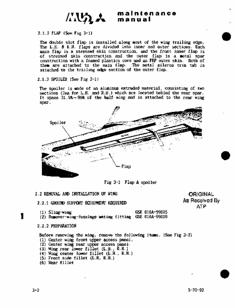
c~r m a 5 a t a a a a ce
manual
2.1.2 FLAP (See Fig 3-1)
The double slot flap is installed along most of the wing trailing edge.The L.H. R.H. flaps are divided into inner and outer sections. Each
main flap is a stressed skin construction, and the front inner flap is
of stressed skin construction and the outer flap is a metal sparconstruction with a foamed plastics core and an FRP outer skin. Both of
them are attached to the main flap. The metal aileron trim tab is
attached to the trailing edge section of the outer flap.
2.1.3 SPOILER (See Fig 3-1)
The spoiler is made of an aluminum extruded material, consisting of two
sections (2ea for L.H. and R.H.) which are located behind the rear spar.It spans 31.5%--96% of the half wing andis attached to the rear wingspar
,p~"
?r!´•
Flap
Fig 3-1 Flap Br spoiler
2.2 REMOVAG AND INSTALLATION OF WING ORIGINAL
2.2.1 GROUND SUPPORT EQUIPMENT REQUIREDAS Received By
AT P
(1) Sling-wing GSE 016A-99025
1 (2) Remwerlringfuselage mating fitting GSE 016A-99029
2.2.2 PREPARATION
Before removing the wing, remove the following items. (See Fig 3-2)(1) Center wing front upper access panel.(2) Center wing rear upper access panel.(3) Wing rear lower fillet (L.H., R.H.)(4) Wing center lower fillet (L.H., R.H.)(5) Front side fillet (L.H, R.H.)(6) Rear fillet
3-2 3-20-92

ire Q ~e ´•la it o:n a is c
~i I
1~
i. Center wing front upper access panel 4~ Wing center lower fillet
2. Center wing rear upper access panel 5. Front side fillet
9. Wing rear lower fillet 6. Rear fillet panel
Fig.’ 3 2 Removal df´•fillets and panels
2. 2. 3 PROCEDURES
/1) Fuel system
(a) Drai~ifuel.
(b) Remove pressurizing air line (W´•. STA 455) for tip tank. (See Fig. 3-3)(c) Remove electric plug of pressurizing air line shutoff valve.
(d) Remove drain lines of L. Il. and R. H´•. boost pump.
(e) Remove drain line of center fuel tank.
~2) Engine
(a) Insert rig pin into pulley of engine control cable at F. STA 8035.
(b) Remove turnbuckles (8 ea. of engine control cable located behind the rear
center wing spar.
(3) Air conditioning and wing de-icer’system (See Fig. 3-4)
(a) :DisconneCt air pressure line at L. Il; side of center wing trailing edge.(F. STA 6215)
(b) Remove ducts for engine bleedair at both side of center wing trailing edge.(See Fig. 3-5)
(c) Disconnect wing de-icer line at R. H. side of center wing leading edge.(F. STA 4745)
(4) Electrical and instrument system
(a) Remove elec.tric~l piugs P255, P26, P257 P258,- P275 (*2) ,´•P276 ("2)
P483..(*1´•) ,´•P484’(*1), P486 (*2) and P490 at both sides of center wing
leading edge´•.
*1 Aircraft´• S/N 652SA
*2 Aircraft S/N. 661SA,~ 697SA and subsequent 3-3

oa a a i~i t a h a a C a
la a n a a
(b) Remove electrical panel assembly located at center wing leading edge.(Bee Fig. 3-6)
(c) Disconnect electric wire (fuselage side) from terminal blocks TB405,TB406 and TB407 ("2) at center wing trailing edge and disconnect
electric wire for generator from 5277 and 5278,
(d) Remove bonding jumper at center wing trailing edge, (F. STA 6125)(See Fig. 3-7)
(e) Remove electric wire’of left and right boost pumps from boost pump line filters.
(f) Remove two clamps binding electric wire and located at center wing trailingedge. CW. STA 6125)
(g) Disconnect tubing for vacuum system for the gyro drive from elbow at center
wing leading edge.
(h) Disconnect auto-pilot cable (if installed), (See Fig. 3-8)
"2 Aircraft S/N 661SA, 697SA and subsequent
;II----;--´•
-d
j ii r
ORIGINAL
Fig, 3-3 Removal of pressurizing Fig. 3-4 Removal of turnbuckleAS Received By
air line for tip tank AT Pfor engine control cable
Yir~r
I‘i~TI r ´•s~n
’f ,/’ji 3 ii j I´•d
I I. it
Fig. 3-5 Removal of bleed air Fig. 3-6 Removal of electric
duct panel assembly
3-4

/P~i5 It no ail nQ a n a n ~e a
no a a a a(
(5) Flight´• control system
(a) R~move control cable of spoiler control system at denter wing trailing edge.
(FSTA 5772) (See Fig. 3-8)
(i) Loosen´•turnbuckle of cable, under the floor, F. STA 6725.
(ii) Remove retainer: from’cable fitting of quadrant in ditferential linkage.
~´•i:;´•"i:
Fig. 3-7 Removal of bonding Fig. 3-8 Removal of spoiler control
jumper cable
(6) Wing
(a) Lift wing with slidg fixtures attached at 3 points on W. STA O of the upper front
spar surface and W. STA 1150 of~ the upper rear spar surface (both sid~s).Remove rear spar wing-fuseiage connection bolts first and then front spar wing-
fuselage connection bolts. (See Fig. 3-9)
(b) .Lift wing,. in such- a manner’that, no impact:load is applied to the wing.Rest’it on a dolly with supports at W. STA 3950: (both sides).
CAUTION
Walk only on spar flanges or ribs. Do not stepon the forward or rear wing fillets.
ORIGINAL
As Received ByAT P
3-5

maintenancem a n.u a I
Rear spar After installing
attaching bolt
Front spar I~ with 6 to 25 in-
Ibs (7 to 29 kg/cm)
j", C c´• of torque, install
cotter pin.
1io cc
cc 3
After instal’ling attaching bolt with 24~89 in-lbs (28~103 kg-cm)
of torque, install cotter pin.
i. Front spar fitting 2. Attaching holt
3. Rear spar fitting 4. Attaching bolt
Fig. 3 9 Removal of wing
2. 3 REMOVAL AND INSTALLATION OF OUTER WING (See Fig. 3-10)
(1) Remove inboard and outboard flap assemblies in accordance with Para. 9. 2,
CHAPTER V, Flight Control System.
(2) Remove spoiler assembly in accordance with Para. 5. 2, CHAPTER V, FlightControl System.
(3) Remove outer wing side access panel of inner and outer wing connecting section.
(4) Remove access panel at outer wing leading edge lower surface. (W. STA 2800)
(5) Disconnect fuel vent line at W. STA 2810.
(6) Disconnect hose for wing leading edge de-icer boots at W. STA 2870.
(7) Disconnect pressurizing air line for tip tank at W. STA 2770.
(8) Disconnect fuel transfer line for tip tank at W. STA 2680.
(9) (*1) Remove electrical plug from receptacle 5415 located at inner wingleading edge W STAi590, and 5441 located at outer wing leading edgeW STA2770.
(*2) Remove electrical plug from receptable (5441, 5415 or 5401 for L.H.
and 5442, 5416 or 5402 forR.H.) located at outer wing leading edge.(W. STA2785)
(10) Remove nacelle upper access panel at W. STA 2300.
(11) Disconnect fuel transfer line for outer wing at W. STA 1950.
(12) Remove inner and outer wing attaching bolts (4 ea.
(13) Rej.nstall in reverse sequence of removal.
Take care of the following items when installing outer wing.
~1 Aircraft S/N 652SA3-G .*2 Aircraft S/N 661SA, 697SA and subsequent
6-1-79

maintenancemanual
(a) Apply rust preventive oil (MI1-C-16173 grade i, MIL-C-11796class 3 or MIL-C-16173 grade 2) on bolt shank when installingbolt.
(b) Installation torque values for bolts are as follows;
Rear spar upper 690--´• 990 in-lbs
Front spar upper 1000^´• 1440 in-lbs
Rear spar lower 1300cy 2160 in-lbs
Front spar lower 2500cv 4500 in-lbs
When attachment is used on top of torque wrench, torque values are corrected
as follows:Wrench length x torque value specified above
Corrected torque valueWrench length attachment length
Outer wingrear spar
Outer wing; fitting
1
aid‘’"E----
Outer wing front spar fitting
Fig. 3-10 Removal of outer wing
2. 4 REMOVAL AND ~INSTALLATION OF WING LEADING EDGE (See Fig. 3-11)
(1) Remove upper and lower covers of wing front spar, W. STA 1100´•--1300.
(2) Pull out hinge pins (lea. upper and lower) running from W. STA 580 throughW. STA 1950.
(3) Disconnect hose of boot.
(4) Remove wing leading edge.Reinstall in reverse sequence of removal.
ORIGINAL
As Received ByAT P :I-
:iejl
Fig 3 II Removal of wing leading edge3-31-90 3-7

maintenancemanual
3. EMPENNAGE
3. 1 GENERAL DESCRIPTION
The empennage consists of a horizontal stabilizer, elevator, vertical stabilizer,and rudder. Trim tabs are attached to the trailing edges of the elevator and
rudde r.
Empennage also includes the detachable dorsal fin made of FRP and horizontal
stabilizer leading edge fillet made of metal.
The horizontal stabilizer is all metal, integral, (L. H. and R. H. 2 spar,
stressed-skin construction and is attached to fuselage with 4 bolts.
The vertical stabilizer is all metal (except the tip), cantilever, 2 spar, stressed
skin construction and is attached to the aft fuselage.The 18.5 in. (470rmn) long tip section is made of FRP for VHF antenna installation.
The elevator is all metal, mono-spar, stressed skin construction with both L. H.
and R. H. sections made in one piece connected by a torque tube. The elevator is
attached to the horizontal stabilizer at a central hinge and 2 hinges on each side.
Rudder is all metal (except the tip which is made of FRP), mono-spar, stressed
skin construction and is attached to the vertical stabilizer with 2 hinges.
3. 2 REMOVAL AND INSTALLATION OF EMPENNAGE
3. 2. 1 HORIZONTAL STA BILIZ ER
(1) Remove tail cone, horizontal stabilizer leading edge fillet, and inspectionpanel between F. STA 9903. 5 10240.
i2) Remove elevator control cable at turnbuckle, F. STA 8605
fMain-Aft fuselage mating point).
(3) Remove trim tab control cable at turnbuckles, F. STA 8370 and 9625.
(4) Remove elevator control cable terminal at elevator quadrant. (See Fig. 3-12)
NOT IE
After removing control cable on the main fuselage,keep the cable in tension by means of rubber cord.
It is not necessary to remove down spring.
Rigging pin is to be inserted at quadrant section.
(5) Remove clamp at the fuselage frame section, F. STA 9903.5, and remove hose
for de-icing system. (See Fig. 3-13)
(6) Remove bonding jumper.
(7) Remove rear spar stabilizer-fuselage connecting bolts, and then remove front i
spar stabilizer-fuselage connecting bolts. (See Fig.3-14 and Fig. 3-15)
(8) Pull horizontal stabilizer rearward.
(9) Install in reverse sequence of the removal.
3-8 3-31-90

maintenancemanual
NOTE
To install horizontal stabilizer, install stabi lizer-
fuselage connecting bolts in forward spar before
installing stabilizer-fuselage connecting bolts in rear
spar, and then install the bolts-in rear spar.
3.2.2 VERTICAL STABILIZER
(1) Remove tail cone dorsal cover, fillet and access cover at FUS. STA
9903.5 thru 10240.
(2) Disconnect tail light electric wire at terminal block (TB319).
(3) Disconnect rudder control cable at turnbuckle located on FUS. STA 8605
(main fuselage to rear fuselage connection).
(4) Disconnect rudder trim tab control cable at turnbuckle locate on FUS.STA 9625.
NOTE
Maintain keep the tension, after disconnecting control
or other suitable means.cablesin the forward fuselage side with rubber cords
(5) Remove anti-ice equipment hose after removing clamps at forward toppart of FUS. STA 9195 fuselage frame.
(6) Remove rudder from vertical stabilizer in accordance with Chapter 5,paragraph 4-2.
(7) Remove bolts connecting front spar fittings to fuselage while hangingvertical stabilizer in a suitable manner. Next, remove bolts connectingrear spar fittings to fuselage.
NOTE
Secure the shims (etc) used on surface contacting with
fuselage side fittings, to the fuselage or to the
vertical stabilizer in a suitable manner in order to
keep them from becoming lost.
NOTE
Record the number and location of shims.
3-31-90 3-9

c~ Itmaintenancemanual
(8) Remove the vertical stabilizer lifting slowly upward taking carethat
undue pressure is not exerted between the spar fitting and the fuselageside fitting.
(9) Install in reverse sequence of removal.
3.2.3 ELEVATOR AND RUDDER
For removal and installation of elevator, see Chapter V section 3.2, and
for removal and installation of rudder, see Chapter V section 4.2 of this
manual
I~
dA I,
s"5
:e
´•;b
Remove elevator control cable fitting Remove hose for de-icing systemFig. 3-12 Fig. 3-13
E
,~L1L;
ii$"
3L~
Tighten stabilizer-fuselage connecting Tighten stabilizer-fuselage connectingbolt in forward spar with a torque of bolt in rear spar with a torque of 140
60 to 85 in-lbs (69 to 98 kg-cm) and to 203 in-lbs (161 to 234 kg-cm) and
apply alignment mark. If it is hard apply alignment mark.
to install cotter pin, nut may be
tightened up to 140 in-lbs (161 kg-cm) Fig. 3-15
torque maximum.
Fig. 3-14ORIGINAL
As Received By3-10 AT P 3-31-90
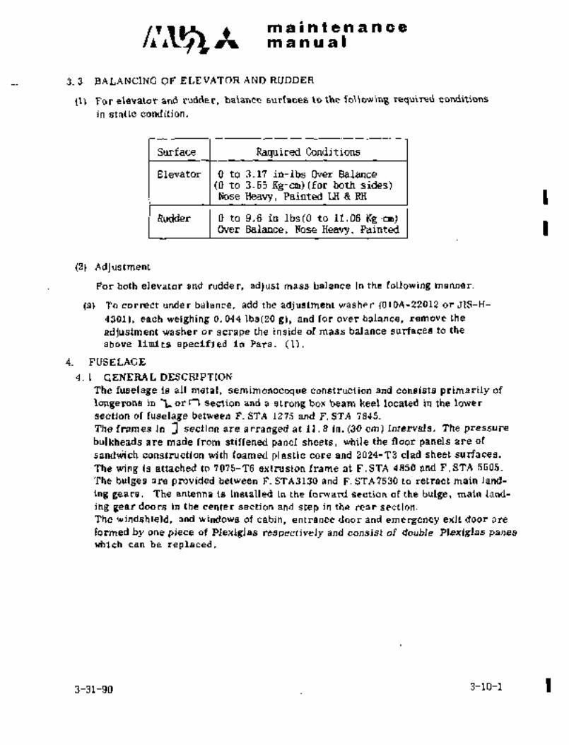
matmanualntenance
3. 3 BALANCING OF ELEVATOR AND RUDDER
(1S For elevator and rudder, balance surfaces to the required conditions
in static condition.
Surface Raquired Conditions
Elevator 0 to 3.17 in-lbs Over Balance(0 to 3.65 Kg-cm)(for both sides)Nose Heavy, Painted LH RH
Rudder 0 to 9.6 in-lbs(0 to 11.06 Kg-cm)Over Balance, Nose Heavy, Painted
(2) Adjustment
For both elevator and rudder, adjust mass balance in the following manner.
(a) To correct under balance, add the adjustment washer (0l0A-22012 or JIS-H-
4301), eac~h weighing 0. 044 lbs(20 g), and far over balance, remove the
adjustment washer or scrape the inside of mass balance surfaces to the
above limits specified in Para. (1).
4. FUSELAGE
4. 1 GENERA L ’DESCRIPTION
The fuselage is all metal, semimonocoque construction and consists primarily of
longerons in 1 or T\ section and a strong box beam keel located in the lower
section of fuselage between F. STA 1275 and F. STA 7845.
The frames In 3 section are arranged at 11.8 in. (30 cm) intervals. The pressure
bulkheads are made from stiffened panel sheets, while the floor panels are of
sand~ich construction with foamed plastic core and 2024-’13 clad sheet surfaces.
The wing Is attached to 7075-T6 extrusion frame at F.STA 4850 and F.STA 5605.
The bulges are provided between F. STA3130 and F. STA7530 to retract main land-
ing gears. The antenna is installed in the forward section of the bulge, main Land-
ing gear doors in the center section and step in the rear section.
The windshield, and windows of cabin, entrance door and emergency exit door are
formed by one piece of Plexiglas respectively and consist of double Plexiglas panes
which can be replaced.
3-31-90 3-10-1

!~B L~4 maintenancemanual
4. 2 NOSE CONE
4. 2. 1 REMOVAL AND INSTALLATION (See Fig. 3-16)
(1) Remove electronics compartment door and inspection doors (F. STA1B0
1080).
(2) Supporting nose cone, remove attaching bolts at F. STA180 frame.
(3) Install in reverse sequence of removal.
(4) After installation, seal the gap between nose cone and F. STA1SO frame
with sealant PR341 so that mold line is flush.
1 C~UTIONCAUT ION
Nose cone should be handted
with care.
:1-10-2 3-31-90

m a I!ntenan a. a
na a a a a I;
1L~ zA
U.
i. Nose cone
2. fastener
3. Electronics compartment door
Fig. 3-16 Nose cone and electronic compartment door
4. 3 ’ELECTRONICS COMPARTM´•E´•NT DOOR (See Fig. 3-16)
4. 3. 1 REMOVAL AND INSTALLATION
(1) Turn quarter-turn fasteners counterclockwise to disconnect.
(2) Remove the door frpm the airframe.
(3) Install in reverse sequence of removal.
4. 4 ENTRANCE DOOR
4. 4. 1 CONST´•RUCTION (See Fig. 3-17)
;The entrance door is opened outward, attached to the airframe with hinges at
the front end of the door. It opens forward to about 112 degrees. The door latch-
ing rods engage five~ steel latch plates on each side of the fuselage door frame,
four at the corners and the one at rear side serves as an open lock:
The door has inside and outside handles O at about the center of door and the
handles are connected mechanically to latch rods It is possible to lock or
unlock the door by rotating handle. When latch rod is in unlocked position, a
warning light notifies pilots of danger. Pressure lock mechanism and open
3-11

/I~CS m a II at a a a a a a
m an a a I
lock mechanism are provided to p~revent handle from being turned while cabin
pressurization is on or the door is’opened. As the cabin is pressurized, an
inflatable seal is provided on the entrance door for pressure sealing.The key lock is located on the outside door handle and is operated by pushing and
turning the key clockwise approximately 180 degrees. A chloroprene rubber seal
is also provided as a weather seal when the inflatable seal is not inflated.
In the center of the door at hinge side, a gust lock device is provided to keepthe door open even in the wind below 15 Kts.
4. 4. 2 REMOVAL AND INSTALLATION
(1) Remove a qpring for gust lock device.
(2) Remove dot buttons.
(3) Remove retainerrings and remove pins.
(4) Install in reverse sequence of removal.
~(5) Remove and reinstall window according to Para. 5. 3. 1 and 5. 3. 2.
4. 4. 3 INSPECTION
(1) Door handle can be operated by not more than 30 Ibs (13.6 kgs) when
pulled~down to a point 1 in. (25 rmn) inside of the handle edge.
(2) When the door is closed, a tight fit is obtained by pushing down the latch rod
inside the cabin.
(3) Latch rod is correctly adjusted.
(4) Handle stopper is correctly adjusted.
(5) Rubber seal´•shows no indication of damage;
(6) Cable tension is correctly adjusted.
4. 4. 4 ADJUSTMENT
(1) Adjustment of handle operat’ing force.
Adjust the position of bracket at the door frame.
Adjustments should be made in the following sequence.
(a) center bracket of rear side
(b) upper bracket of rear side
(c) lower bracket of rear side
(d) upper bracket of front side
(e) lower bracket of front side
Airplane should not be on jacks and fuel tanks should be empty if possible.
NOTE
(i) Missmatch between door and skin is not more
than 0. 06 in. (1.5 rmn).
(ii Shim and used’once should not be reused.
(iii) Installation torque for bolt and O is 75´•u 100 in-lbs.
(86 to 115 kg-cm).
(2) Adjustment of latch rod clearance (See Fig 3-17 Detail A)Loosen bolt and adjust spring in the installed position. Installation torquefor bolt is 75~ 100 in-lbs. (86 to 115 kg-cm).
3-12
6-1-79

PB~ bllWf8nsn c´•e:tm a a a al
%236 3537 34
1L3
B Latch :O
22 21 22 9
.Contact surface of
latch (fixed) and bracket a B I;~= UP 0. 315f0. 02 in.’9 \7 ’6 ’5
A Latch (8f0. 5 mm)Center 0. 276f0, 02 in. 2’7 27 24
(7 f 0.5 mm)Down 0. 2f 0. 02 in. zs-
z F,
j5 =t 0. 5 mm)L?= Up 2. 284 0..02 in.
29-~
~5 (58~0.´•5 mm)Center 2. 284f 0. 02 in.
1 29
(58~0.5 mm) t\3ODown 2. 244f 0. 02 in,
(57f0.5 mm)C H3ndle
Cmechanism
´•8
121
’3
82 ii D Air inlet
38
33 82
1Toseaisuppart
6 Compressed air
:~P ON 0~ 04 in. (0-i mm)
6 40 16
8~"E jj 3"
A Is FSeal should not come out
34
i. Dot button 11. Handle feeling 20. Bolt 30. Center latch
2. Pin mechanism 21. Rdd assembly mechanism
3. Retainer ring 12. Open lock 22. Adjusting nut 31´• Clamp-air inlet
mechanism 23. Gear Box 32. Seal support4. Hinge
5. Outside handle 13´• Crank 24. Stop 33. Hose
6. Key 14. Quadrant crank 25. Bolt 34. L;atch (fixed)
.7. Window glass 15´• Weather seal 26. Nut 35, Bracket
8, Turnb;uckle 16´• Inflatable seal 27. Bolt 36. Shim
9. L~atcki.rod 17. Bracket 28. Nut. 37. Bolt
10. Pressure lock 18. Shim 29. Cable 38. Gust lock device
mechanism19’ Spring 39. Roller
Fig. 3-17 ´•Entrance door 40. Spring
3-13
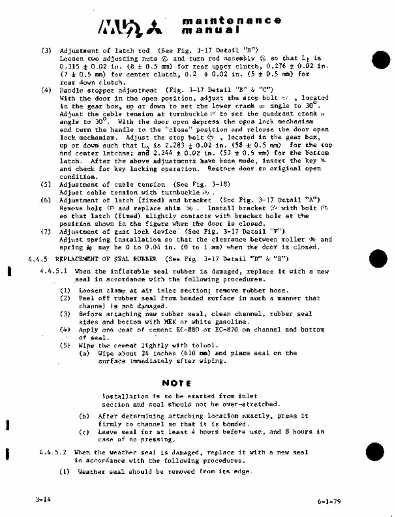
It ~in a at a a a a a a
m a a us I
(3) Adjustment of latch rod (See Fig. 3-17 Detail "B")Loosen two adjusting nuts e and turn rod assembly so that L1is(8f 0.5 mm) for rear upper clutch, 0.276 f 0.02 in.0.315 0.02 in.
(7 f 0.5 rmn) forcenter clutch, 0.2 -f 0.02 in. (5 f 0.5 mm) for
rear down clutch.
(4) Handle stopper adjustment (Fig. 3-17 Detail "B" "C")With the door in the openposition, adjust the stop bolt ,~a located
in the gear box, up or down to set the lower crank (In! angle to 300Adjust the cable tension at turnbuckle CH! to set the quadrant crank ci~
angle to 300 With the door open depress the open lock mech~nism
and turn the handle to the "close" position and release the door open
lock mechanism. Adjust the stop bolt located in the gear box,
up~ or down such that L is 2.283 0.02 in. (58 0.5 mm) for the topand, center latches; an~ 2.244 f 0.02 in. (57 f 0.5 mm) for the bottom
latch. After the above adjustments have been made, insert the keyand check for key locking operation. Restore door to original open
condition.
(5) Adjustment ofr cable tension (See Fig. 3-18)
Adjust cable tension with turnbuckle C~
(6) Adjustment of~latch (fixed) and bracket ~(See Fig. 3-17 Detail "A")Remove bolt and replace shlm Install bracket with bolt Oso that latch (fixed) slightly contacts with bracket hole at the
position shown in the figure when the door is closed.
(7) Adjustment of gust lock device (See Fig. 3-17 Detail "F")
Adjust spring installation so that the clearance between roller and
spring I~ may be O to 0.04 in. (0 to 1 mm) when the door is closed.
4.4.5 REPLACEMENT OF SEAL RUBBER (See Fig. 3-~17 Detail "D" "E")
4.4.5.1 When the inflatable seal rubber is damaged, replace it with a new
seal in accordance with the following procedureS.
(1) Loosen clamp at air~inlet section; remove rubber hose.
(2) Peel off rubber seal from bonded surface in such a manner that
channel is not’damaged.(3) Before attaching new rubber seal, clean channel,rubber seal
sides and bottom with MEK or white gasoline.(4) Apply one coat of cement EC-880 or EC-870 on channel and bottom
of seal.
(5) Wipe the cement lightly with toluol.
(a) Wipe about 24 inches (610 mm) and place seal on the
surface immediately after wiping.
NOTE
Installation is to be started from inlet
section and seal should not be over-stretched.
(b) After determining attaching location exactly, press it
’firmly to channel so that it is bonded.
(c) Leave seal for at least 4 hours before use, and 8 hours in
case of no pressing.
4.4.5.2 When the weather seal is damaged, replace it with a new seal
in accordance with the following procedures.
(1) Weather seal should be removed from its edge.
3-14 6-1-79

C~jS m a nt a a a a a a
m a nu is Ikg Ib
so
30
fio
20rn 40d tolerance: +7 -0 Ibs
10 (+3.2,-0kg´•)to
i V(I i I I i 1 ]´•I I i I I Fig 3-18 Tension of entrance
-zo -~o o ~o to 80 40 door cable
Atmospheric temper;atiire OC
(2):T3efore cementing, clean the surface with MEK or white gasoline.
(3).Apply one coat of cement EC-880 or’EC-870 (Sumitomo, 3M) in
accordance with the same procedures as inflatableseal, When the door
i’s closed, weather seal shduld not come out from clearance.
4.4.6 OPERATlONAL CHECK dF PRESSURE LOCKMECHANISM i i I A
Operate’the pressure lock mechanism by pressurizedair~P (15 psi) and measure the length´•of;stroke A.A shall be 0; 63 0. 04 in. (16f 1 mm).In accordance with the procedure described in Para,
3.9.i, Chapter VIII, the pressure lock mechanism
can be operated by pressurized air of 15 psi,(l kg/ccX).
´•4. 5 EMERGENCY EXIT DOOR
a. 5. 1 CONSTRUCTION (See Fig 3-19) P
The emergency exit door, located on the R. H. side beneath the wing, is openedinwar~d. Pressure load is carried by the 4 upper and lower hooks of the door
on the airframe side, and the air load, from outside of airframe, is carried by2 latchpins C2) in the lower sectionof the door and the latch pin~ in upper section
of door. The rub~ber seal around the door comes in close contact with the
striker on the airframe side.for a pressure-tight seal.
4. 5. 2 TO OPEN THE DOOR
(1) Pullthe handle O until it reaches the stop and the bell crank O rotates and
the latch pin O disengages.
(2) Open the door, supporting it with the hands since it falls inward with 2 latch
pins in the lower serration plate as hinges.
4. 5. 3 ADJUSTMENT
(1) Adjustment of door
(a) Circumference of do;or (See Fig. 3-19 Detail "A")
Mating of the door pin~bjand the hook~on the airframe side can be adjusted
by increasing or decreasing the number of washers
(b) Radial direction of door (See Fig. 3-19 Detail "B", "C")
Adjust the hook and the serration plate aD on the airframe by moving
them in and out so there is no play in the in-and-out direction with the
door closed.
3-156-1-79

m a Intenancem a nua)
1. Fork
2. Latch pin
3. Center latch pin
4. Handle
5. Bell crank
6. Roller
7. Stop
\2\ Plilll 11 8. Washer
9. Hook
10. Pin
11. Serration plate
12. Sealrubber
)b A a
II
’J~
L8 DLg= O. 236in.
(6 mm)~L
6 LP
7 4
Lz=O. 197in. (5 mm) LI=O. 236 in.
Fig 3 19 Emergency exit door (6 mm)
(2) Mechanical adjustment
(a) Mating of the latch pin O and the fork on the airframe side is adjusted bymeans of the fork thread so that the protrusion of the latch pin LQ is 0. 236
in. (6 mm). (See Fig. 3-19 Detail "C")
(b) Adjust fork thread so that roller and latch pin are in contact.
(See Fig. 3-19 Detail "C")
3-16
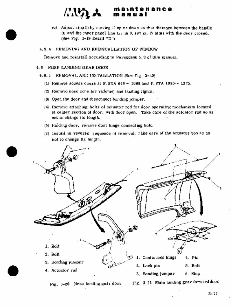
clr~s It~ al a Int a a a a a a
manual
(c) Adjust stop O by movi~ it up or down so that distance between the handle
(See Fig. 3-19 Detail "D")~and the inner panel line Lz is 0. 197 in. (5 mm) with the door closed.
4. 5. 4 REMOVING AND -REINSTA LLATION OF WINDOW
Remove and reii~stall according to Paragraph 5. 3 of this manual.
4. 6´• NOSE LANDING GEAR DOOR
4. 6, 1 REMOT~J"AL AND INSTALLATION (See Fig. 3-20)
Remove access doors at F. STA 640 N 1080 and F. STA 1080- 1275.
(2) Remove nose cone (or radome) and landing lights.
(3) Open the door and disconnect bonding jumper.
(4) Remove attaching bolts of actuator rod for door operating mechanism located
at center section of door, with door open. Take careof the actuator rod so as
not to change its´•length.
(5) Holding door, remove door hinge connecting bolt.
(6) Install in reverse ~sequence of´•removal. Take care of the actuator rod so as
not to change its length.
a
1. Bolt
i1. Continuous hinge 4. Pin
2; Bolt
3. Bonding jurhper f~2. Lockpin 5. Bolt
4. Actuator rod3. Bonding jumper 8. Stop
Fig. 3-20 Nose.landing geardoor Fig. 3-21 Mainllanding gear fonvard~door
3-17

C~g ~t sna a I~ li t a a a a 8a 19 iil a IO
4. 7 MAIN LANDI~C.GEAR FORWARD DOOR
4. 7. 1 AND
The main landing gear door is located at the side of bulge between F. S’rA
4265 and P. STA 5215. Two continuq~us hihges are provided in the upper section
of the door. The link mechanism with iridependent actuator opens or closes the
ddoi´• befo~e ok´• after gear retractibn anil 8xtension.
Lilik mechanism, bperated by a mdtor, locks or i~nlocks the door in openingor closing.
4. 7. 2 REMOVAL AND INSTALLATION ~See Fig. 3-21)
(1) Open the door and hold it open with rope or chain,etc.
Disconnect electrical system.
(2) Remove nuts connecting door and link mechanism and disconnect bonding
jumper.
(3) Remove stop.
(4) Remove hinge pin in upper section.
(5) Install in reverse sequence of removal.
4. 8 MAIN LANDING GEAR AFT DOOR
4. 8. 1 CONSTRUCTION AND FUNCTION
This door is located at the side of bulge between F. STA 5120 and F. STA 5830,
and connected by a continuous hinge provided in upper section of door. The
connecting rod of the main landing gear is attached to the door, so the door closes
or opens together with main landing gear. The door is locked by a lock pin when
the door is closed. 1
-I z
1. Continuous hinge~a 2. Pin
3. Lockpin4. ´•Bolt
I >~1 5. Bonding jumper
Fig. 3-´•2i Main landing gear aft door
3-18

is ii a a I
4; s. 2 E1EMbVI\L A~jD iNSTALjLATION (See Fig. 9-22)
(1) Remove pin connecting fi´•ont door to connecting rod and disconnect bondingJumper.
(2) Remdve c;btter pin and hinge pin from upper hinge section and remove the
door.
(3) Install in reverse ~sequence of removal.
i. Entrance door7
1P
2; Step body3. Lever If4. Lever
5. Adjusting rod 13
6. Lever
7. Torque tube
8. Bracket17
9. Bracket
10. Spring --1211. Bracket
12. Adjusting13. Shim
14. Adjusting bolt
15.. Screw
16. Bolt16 4
17; Bolt´• 3
Fig. 3-23 Step assembly and mechanism
4. 9 STEP ASSEMBL~Y
4, 9. 1 CONSTRUCTION~:.
The~ step assembly consis.ts of the step:body ’and operating mechanism, and is
provided in space,: rear oSthe ]bulge, under the entrance door and connected
mechanically to the entrance door.
When~the entrance door is´•opened by’half (about 77"), ´•´•the stepO is fully opened,then the door moves individually for further opening (See Fig. 3-2~3)..
3-19

i
mai~ni4nancenn a or a a I
4.9,2 REMdVAL ANd
(1) Open the step.
(2) Remove screw O and bolt
(3) ~o’inst811, tighten screw O and bolt
4, 9. 3 ADJUSTMENT
(1) To level the step, adjust by the rod O and bort~
(2) In case of mismatch between step and bulge skin when the step is closed, adjust
by the rod O and bracketO.
(3) Installation torque for boltO is 75 N 100 in-lbs. (86 to 115 kg-cm).
NOT E
i. Mismatch between step and bulge sltin shall
be less than 0. 04 in. (1 mm).
ii. Removed shim O should not be reused.
4. 10 CABIN FLOOR (See Fig. 3-24)
4. 10. 1 CONSTRUCTION
The cabin floors consist of six sandwich panels’ with a foamed plastic core, and
are attached to the floor-support members with screws. The two forward floors
are detachable but the four rear floors can not be detached, since they cdnstitute
a pressure bulkhead.
The rails for pilot seats and passenger se.ats are screwed on the floors.
Inspection panels for the landing gear operating mechanism and the emergency
landing gear extension mechanism are located in the two forward floors.
4. 10. 2 REMOVAL AND INSTALLATION
(1) Remove screws attaching rails for pilot seats and passenger seats.
(2) Remove screws from the floor panels and floor panel support member, and
remove the floors.
(3) install in rederse sequence of removal.

~a Csni:e-nu Ph c9
n~ a n a is I
:4 I, Forward flodr
C1 2. Center~floor
3. Aft floor
4. Inspection panel-landinggear mechanical stop
5. Inspection panel-emergencylanding gear extension
mechanism
6. Track
7. Floor side cover
Pig 3~2i Reinstailation of: cabin floor
4. 11 AFT FUSELAG~
4. 11. 1 GROUND SUPPORT: EQUIPMENT REUIRED
Sling aft fuselage (GSE 016A-99046)
4. 11. 2 REMOVAL AND INSTALLATJON
(1) Remove tail cone. (See Fig. ´•3-25)
(2) Remove.the dorsal fin in front of F. STA 8895. .(see Fig. 3-26)
3-21

mi a 8 bi P a ’Bm a a a cC~~i a a a a I
(3) Disconnect elevgtoi~ and rudder trim tab
control cables at tii~ turnijuckIes in
F. STA 8370 and 9625.
(See Fig. 3-27 and 28)
(4j Disconnect the lines for electric systemand de-icing system iri leading edgesof vertical and horizontal stabilizer.
(See Fig. 3-29 and.30)
(5) Remove rubber hose from adapter of ram
air discharge port of the refrigerationunit.
Fig. 3-25 Removaloftailcone
ORIGINALAs Received By
AT P
JA873´•8
i´•
Fig. 3-26 Removal of dorsal fin
I
a ;ir
F
id:
.L’"´•.
F,ig. 3-27 Removalofelevator Fig. 3-28 Removal of rudder trim tab
trim tab control cable control cable
3-22
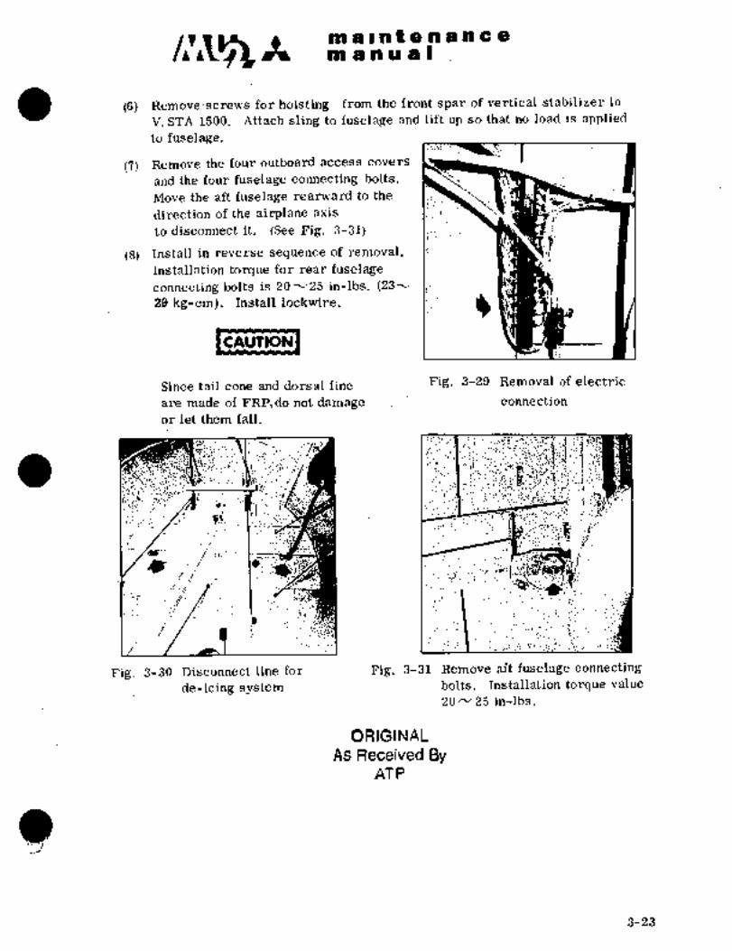
c~s m a’l n~t a a a a c a
as a a a a I
(6j Remove screws for hoisting from the front spar of vertical stabilizer in
V.’STA 1500, Attach sling to fuselage and Idt up so that no load is applied
to fuselage.
(7) Remove the four outboard access covers
and the four fuselage connecting bolts,
Move the~aft fuselage rearward to the
direction of the airplane axis
to disconnect it, (See Fig. 3-31)
(8) Install in.’reverse sequence of removal,
Installatidn torque for rear fuselage
connecting bolts is 20~25 in-lbs, (23^´•
29 kg-cm), ~Install lockwire,
CAUTION
Since tail cone and dorsal fine Fig, 3-29 Removal of electric
are made of FRP,do not damage connection
or let them fall,
;:h~-.I;;´•
*":´•9,.. a;
.i 8:i-d
Mci.
´•i´•~
;~i*
I:8
i/ ,:i i".,i
´•´•r: I´•LC;
Fig. 3-30 Disconn’ect line for Fig, 3-31 Remove aft fuselage connecting
de-icing system bolts, Installation torque value
20 25 in-lbs,
ORIGINAL
As Received ByAT P
3-23

m a Int a a a a a a
m~ anual
5. WINDSHIELD AND CABIN WINDOW
5.1 GENERAL DESCRIPTION
Applicable to Aircraft S/N 652SA
Windshield.consists of two panes of front and side glass. Each pane is
contoured and formed from one piece of acrylic plastic. Frorit outer pane
is 0.312~in. (7.925 mm) and outer pane 0.25 in. (6.35 mm) thick. The partsof front pane and side outer pane which are attached to airframe are
reinforced with glass fabric (FRP). Screw holes are provided on the re-
’inforced part to install. Front and side inner panes are installed to
airframe.thkough very soft sponge.r’ubber.
Applicable to.Aircraft S/N 661SA’, 697SA and’ subsequent
The windshield consists of two panes, inner and outer. The inner panes are
contoured and formed from one piece acrylic plastic 0.i87 in. (4.75 mm) thick.
The outer pane consists of two, an inner and outer tempered glass ply with a
vinyl sandwiched between them. The outer pane glass plies are designed to bear
the cabin internal pressure and flight loads. The outer pane windshield is of
a fail safe construction and vinyl ply. The outer pane vinyl ply contains a
heating element for flight during icing conditions. Refer to Section IX
"Anti-Atmospheric System" for details, operation and maintenance.
Each side window consists o’f two‘panes, inner and outer. Each pane is con-
toured and formed from one piece acrylic plastic; inner pane thickness is
O.lsj in. (4.75 mm), whereas the outer pane thickness is 0.25 in. (6.35 mm).Each pane is constructed with a fiber reinforced glass and is installed to
the airframe in this area. The inner panes are installed through a soft
sponge rubber.
5.2 REMOVAL AND INSTALLATION OF WINDSHIELD
CAUTION
Since the aircraft is pressurized,handle front and outer side panes
with care. Special attention should
be paid not to damage with knife, etc.,when installing or removal of glassor masking work in painting.
5.2.1 REMOVAL OF FRONT PANE (See Fig 3-32)
(1) Remove shroud and instrument panel (See Chapter X, Para. 1.4),
1 (2) Remove screws and inner glass assembly (S/N 652SA only).
-d(3) Remove screws and upper inside panel.(4) Ijisconnect wires at terminal block and identify wires (except S/N 652SA)(5) Remove screws and glass with retainer outward.
3-24 6-1-79
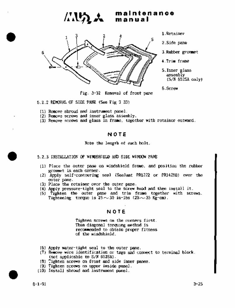
maCnten a. nce
m a~n a a I
1.Retainer3´•24
2.Side pane
6 3.Rubber grommet
4.Trim´•frame
li.Inner glassassembly(S/N’ 652SA only)
G.Screw
Fig. 3-32 Removal Of front pane
5;2.2 REMOVAL OF SIDE PANE (See Fig 3-33)
(1) Remove shroud and instrument panel.(2) Remove screws and inner glass assembly.(3) Remove screws and glass in frame, together with retainer outward.
NOTE
Note the length of each bolt.
5.2.3 INSTALLATION OF WINDSHIELD AND SIDE WINDOW PANE
(1) Place the outer pane on windshield frame, and position the rubber
grommet in each corner.
(2) Apply self-contouring seal (Sealant PR1222 or PR1425B) over the
outer pane.(3) Place the retainer over the outer’pane.(4) Apply pressure-tight seal to the screw head and then install it.
(5) Tighten the outer pane and trim frame together with screws.
Tightening torque is 25/L30 in-l;bs (29N35Kg-cm).
NOT E:
Tighten screws on the corners first.
Then diagonal torquing method is
recommended to obtain proper fitnessolf the windshield.
(6) Apply water-tight seal to the oute’r pane.
(7) Remove wire identification or tags; and connect to terminal block.
(not applicable to S/N 652SA).(8) Tighten screws on front and side ii~ner panes.(9) Tighten screws on upper inside pan;el.
(10) Install shroud and instrument panel.
8-1-91 3-25

n,a5ntenancem a a a a I
NOTE
Wind shield and window glass should be
installed after cleaning the surface
between outer and inner panes.
NOTE
Note the length of each bolt.
5 4 3 ,2 .1 1.Retainer
2.Side pane
3.Rubber grommet
4.Trim frame
5.Inner glass assembly
G.Screw
Fig.3-33 Removal of side pane
5.3.1 REMOVAL
(1) Remove inner glass assembly.(2) Remove rubber duct for defog.(3) Remove screws and outer pane with frame and anele inward.
l.0uter pane
5 4 3 2 1Z.Glass support
13.Trim frame
angle
14.Inner glass
assembly
5.Screw
G.Rubber duct
i 7.Screw
6 7
Rig 3-34 Removal of cabin window
3-26 8-1-91

ni a D a t a a a a a a
m a a a a I
5.3.2 INSTALLATION OF CABIN WINDOW
(sealant PR1222 or PR1425B) over the(1)Apply self-contouring sealouter pane.
(2) Place the outerpane on the window frame; and position the glasssupport angle.
(3) Apply pressure-tight seal to the screw head and then install it.
(4) Tighten the window frame, the outer pane, trim frarhe and glasssupport angle together with screws:
Tightening torque is 25 ~-30 in-lbs. (29N35 Kg-cm)
NOTE
Tighten screws on the corners first.
Then diagonal torquing method is
recommended to obtain proper fitnessof the cabin window.
(5) Apply water-tight seal to the outer pane.(6) Install the inner glass assembly.
NOTE
Window glass should be, installed after
cleaning the surface between outer andinner panes.
NOT~E
Note the length of each bolt.
5.4 WINDSHIELD AND CABIN WINDOW GLASS
5.4.1 INSPECTION
Inspection criteria for acrylic plastic glass is as follows:
(1) Replace with new glass if following conditions are found.:
(a) Total crazed area exceeds one square inch.
(b) Depth of crazing exceeds 5% of panel thickness.(c) Visibility is impaired.
(2) Replace when scratch exceeds O.Of in. (0.25 mm) in depth.
8-1-91 3-27 1

m anua)maCntenance
NOTE
When scratch is less than the value
specified above, glass should bereused after smoothing the scratch.
5.4.2 CLEANING
See Para. 6.8.4 Chapter II, CLEANING INSTRUCTIONS
I 3-28 8-1-91

m.lnieniicotP19 a a a a I
6. CENTER PEDESTAL
6. 1 GENERAL DESCEI~PTION
’The center pedestal is installed in forward i~enter section of the cockpit at F. STA
1650 N F. STA 1820 and contains the mec~ianism to controlthe engines, elevator
and rudder trim t:ab; and parking brakes.
The center pedestal consists of the followings. (See Fig. 3-35)
(1) Engine controlbox (2) Trim contro‘l box
(3) Bell crank assembly (4) Pulley assembly
(5) Parking brake (6). Drum as’s’embly
(7) Switch~panel (8) ~Frame assembly
-7 z~.1. Frame assembly
s 2. ’Engine power lever
3. Engine condition lever
,o_4. Engine control box
C~ B ~-U ,.4 5. Engine switch panela 6. Trim control box
II
7. Rudder trim wheel
,s s~ Elevator trim wheelt%
9. Pulley assembly~B a ~7 10. Bolt-engine .control box
11’. Upper bell~crank8 12. Frictionlever
13. Parking brake leveria
14. Lower bell crank9
15. Drum assembly16. Bolt-frame assembly
17.’ Support-keel
17
uC__jFig: ’3-3 Center.pedestal assembly
3-29

C1~55 It a s a ad 8
ad a a u a I
6.2 AND INS~ALLATION
6. 2. 1 ENGI~JE CONTROit BOX
fl) Remove four rods which art~ to bell crank, from power lever and
cohditioniever. iSee Fig; 3-3i~)
(2) Remove wiring of switch panel fr6m connector 5208 of main junction box..
(See Fig. 3-37)
(3) Remove four bolts for box attachment.
(4) Install in reverse sequence of removal.ORIGINAL
6. 2. 2 TRIM CONTROL BOX (See Fig. 3-38) As Received ByAT P
(1) Remove six screws for box attachment.
(2) Install in reverse sequence of removal.
Fig. 3-36 Removal of rod from Fig. 3-37 Disconnect switch panelbell crank wiring
6. 2. 3 BELL CItANK ASSEMBLY
(I) Remove attaching bolts (8 for upperbell crank and 2 for lower bell
crank) for rods from bell crank.
(2) Remove bearing attaching bolts
(4 for upper and 4 for lower) from
frame assembly.
(3) Install in reverse sequence of’
removal.
Fig. 3-38 Removal of screws
6. 2. 4 PULLEY ASSEMBLY
(P) Remove four bolts of control rods from bell crank.
3-30

~n ii n~ ~i .in rii is E oin ii a a a s
i2) RembGe fo’ur L. H. Blid H. bolts attaching fi-aine gssembljr.
Ri~inoirB t;Ctd bttai=hing bolts at rear ~ide from frame assembly.
Rekinovg foi;lr bolts att~chirig keel.
(5) irist8li ih reverse Of remoii$l.
iv ci ri
Fjrst; remove control cable gnd chain for
engini: and control system.
6. 2; 5 PARKING BRAKE (See E’ig. 3-39)
(1) Disconnect parking brake lever from rod.
ORIGINAL(2)-1 Remove fourscrews and brake lever:assembly.
As Received By(3) Install in reverse sequence of removal. AT P
6. 2. 6 DRUM~ASSEMBLY (See Fig. 3-40)
(1) Remove drum attaching bolt, and drum assembly.
(2) Install in reverse sequence of ~emoval.
Fig. 3-39 Disconnect parking brake Fig. 3-40 Removal ~of drum
levei´• from rod´• 1 .aBsembly
7. STATIC DISCHARGER
Static electric’ity causes disturbances in~aircraft radio equipmenti etc. The.dis-
charger is installed to discharge static electricity collected in- the airframe, so
that airframe electric potential is almost the same as that of the atmpsphe~rearound the aircraft.
The sharper the tip of the discharger, the less equipment noise and the voltage of
the discharging section drops.
.The dischargers´• are installed on wing, horizontal stabilizer and tip´• tai~k. ~CareThe dischdrger controls rapid discharging and prevents noise.
should be taken so that-oil dr dust does pot flow into the discharging section with
rain and that the discharger is not damaged.
3-31(32)

CHAPTER
LANDING GEAR AND
BRAKES

maintenancemanual
CHAPTER IV
LANDING GEAR AND BRAKES
CONTENTS
1. GENERAL 4- 1
1.1 GENERAL DESCRIPTION 4- 1
1.2 LANDING GEAR OPERATION 4- 2
2. NOSE LANDING GEAR 4-3(4)
2.1 GENERAL DESCRIPTION 4-3(4)
2.2 REMOVAL AND INSTALLATION OF NOSE LANDING GEAR 4-3(4)
2.3 NOSE WHEEL 4- 6
2.4 STATIC GROUND WIRE 4- 6
2.5 NOSE LANDING GEAR STRUT 4- 7
2.6 NOSE LANDING GEAR STEERING MECHANISM 4-11
2.7 SHIMMY DAMPER 4-13
2.8 NOSE LANDING GEAR UP INDICATOR SWITCH 4-17
2.9 NOSE LANDING GEAR DOWN LOCK 4-18
2.10 NOSE LANDING GEAR DOOR MECHANISM 4-21
2.11 TORQUE LINK ASSEMBLY 4-22-1 12.12 MAINTENANCE OF NOSE LANDING GEAR 4-23
3. MAIN LANDING GEAR 4-24
3.1 GENERAL DESCRIPTION 4-24
3.2 REMOVAL AND INSTALLATION OF MAIN LANDING GEAR 4-24
3.3 WHEELS 4-24
3.4 BRAKES 4-25
3.5 DRAG STRUT 4-25
3.6 OLEO STRUT 4-27
3.7 LEG ASSEMBLY 4-30
3.8 INSTALLATION AND INSPECTION OF MAIN LANDING GEAR 4-(31)32
3.9 MAIN LANDING GEAR DOOR MECHANISM 4-34
3-31-90 4-i

c~s~tmaintenancemanual
4. LANDING GEAR RETRACTING MECHANISM 4-49
4.1 GENERAL DESCRIPTION 4-49
4.2 NOSE GEAR ACTUATOR 4-49
4.3 DUST COVER 4-52
4.4 MOTOR AND TORQUE LIMITER 4-53
4.5 BALL JOINT ASSEMBLY AND TORQUE SHAFT ASSEMBLY 4-53
4.6 CHAIN ASSEMBLY 4-55
4.7 ADJUSTMENT OF MECHANICAL STOP 4-56
5. OPERATION AND CHECK FOR LANDING GEAR SYSTEM 4-61
5.1 OPERATIONAL TEST 4-61
5.2 OPERATION AND CHECK OF MAIN GEAR FORWARD DOOR 4-63
5.3 OPERATION AND CHECK OF NOSE GEAR DOOR 4-63
5.4 MEASUREMENT OF CURRENT FOR MAIN GEAR DOOR MOTOR 4-64
5.5 MEASUREMENT OF CURRENT FOR LANDING GEAR MOTOR 4-65
6. EMERGENCY GEAR EXTENSION MECHANISM 4-66
6.1 ADJUSTMENT AND OPERATIONAL TEST 4-67
6.2 RESET AND CHECK AFTER EMERGENCY GEAR EXTENSION 4-68
6.3 EMERGENCY GEAR EXTENSION PUSH BUTTON
I (Aircraft S/N 652SA and 661SA) 4-71
7. BRAKE SYSTEM 4-71
7.1 GENERAL DESCRIPTION 4-71
7.2 RESERVOIR 4-73
7.3 MASTER CYLINDER 4-73
7.4 MIXER VALVE 4-74
7.5 PARKING VALVE 4-75
7.6 SWIVEL JOINT 4-75
7.7 BRAKE ASSEMBLY 4-77
7.8 BRAKE LINE 4-78
7.9 MAINTENANCE OF BRAKE SYSTEM 4-78
8. WHEELS AND TIRES 4-79
8.1 GENERAL DESCRIPTION 4-79
8.2 LUBRICATION OF BEARING 4-80
8.3 DISASSEMBLY, REASSEMBLY AND INSPECTION OF NOSE WHEEL 4-80
4-ii 3-31-90

maintenancela manual
8.4 DISASSEMBLY, REASSEMBLY AND INSPECTION OF MAIN WHEELS 4-81
8.5 TIRE´•
9 LANDING GEAR POSITION INDICATING LIGHT AND WARNING SYSTEM 4-85
9.1 LANDING GEAR POSITION INDICATOR LIGHT 4-85
9.2 WARNING SYSTEM 4-85
9.3 ADJUSTMENT AND CHECK 4-86
10. ADJUSTMENT OF LIMIT SWITCH 4-86
10.1 NOSE GEAR DOWN LIMIT SWITCH 4-87
10.2 NOSE GEAR UPIN DICATOR SWITCH (S1 06) ADJUSTM ENT 4-87
10.3 UP ZONE SWITCH 4-88
10.4 UP LIMIT SWITCH 4-88
10.5 MAIN GEAR FORWARD DOOR OPEN LIMIT SWITCH 4-88
10.6 MAIN GEAR FORWARD DOOR CLOSE LIMIT SWITCH 4-89
10.7 MAIN GEAR UP INDICATOR SWITCH 4-89
10.8 MAIN GEAR DOWN INDICATOR SWITCH 4-89
10.9 LANDING GEAR SAFETY SWITCH 4-90
10.10 GROUND DOOR OPEN SWITCH 4-91
10.11 PRORELLER LOW PITCH LIMIT SWITCH 4-91
11. ELECTRIC CIRCUIT 4-92
11.1 GROUND STATIC CONDITION 4-(93)94
11.2 GEAR RETRACTION IN FLIGHT-DOOR OPEN 4-96
11.3 GEAR RETRACTION IN FLIGHT-GEAR UP 4-98
11.4 GEAR RETRACTION IN FLIGHT-DOOR CLOSE 4~100
11.5 GEAR RETRACTION STOP IN FLIGHT 4~102
11.6 GEAR EXTENSION IN FLIGHT-DOOR OPEN 4~104
11.7 GEAR EXTENSION IN FLIGHT-GEAR DOWN 4-106
11.8 GEAR EXTENSION IN FLIGHT-DOOR CLOSE 4-108
11.9 DOOR OPERATION ON GROUND 4-110
12. TROUBLE SHOOTING LANDING GEAR SYSTEM AND BRAKE SYSTEM 4-113
13.~CHECK OF ELECTRICAL COMPONENT 4-116 I13.1 LANDING GEAR UP/DOWN RELAY AND DOOR OPEN/CLOSE RELAY´• 4-116
12-27-99 4-iii

clui2 It malnaeaancem a PO a a O
i. GENERAL
1.1 .GENERAL DESCRIPTION
The landing gear is a r~tractable tricycle type and consists of two
.n~iin gears and steerable nose gear. Landing gear retracting and landing
gear door Bper~ting mech~nisins a~e electric-mechanical type.
1.1.1 LANDING GEAR RETRACTING MECHANISM
Main and nose.gear are connected through torque shafts and´•are retracted or
extendedat the´•.same time by operation of the landing gear motor. In this
system, mechanicalstop and clutch areprovdded andprevent airframe and
retracting mechanism from damage~in case of limit switch failure. Main gear
actuator is also used as´•drag struts and up-lock or down-lock because of
internal screw jack being unreversible. Nose landing gear has down
lock mechanism mechanically connected with nose gear actuator but no up
lock mechanism is necessary because of the actuator being unreversible.
1.1.2 LANDING GEAR DOOR OPERATING MECHANISM
(1) Nose geardoor operdting mechanism
This mechanism is operated together with nose gear strut and
closes the doors in gear up operation, opens the doors during
gear down operation.
(2) Main gear forward door operating mechanism
This mechanism is operated by main gear forward door actuator
which is operated electrically together with landing gear re-
tracting mechanism. If ground door open switch is operatedon theground, the main gear fqrw~rd door can be opened or
closed.
(3) Main gear aft door operating mechanism
Main gear aft door is connected mechanically with main gear´•
oleo strut and operated togetherwiththe strut.
1.1.3 ´•MAIN GEAR.DOOP, LOCK MECHANISM
This mechanism is connected mechaqically with main gear forward door operatingmechanism and ´•locks main gear forward and aft doors respectively when the
doors are fully closed.
.1.1.4 EMERGENCY GEAR EXTENSION MECHANISM
When electric system fails, this system is to perform gear extension manuallyby operating emergency gear extension handle on the floor near the pilot seat.
1.1.5 NOSE GEAR STEERING MECHANISM
This system cdnnects nose gear and rudder´•pedals mechanically when gear is
ext~ended for ground steering. Nose gear and rudder pedals are disconnectedin gear up position’allowing only rudder control.
4-1

CI~Lmaintenancem a a a a I
1.1.6 BRAKE SYSTEM
This system can be operated by either the pilot or co-pilot rudder pedals,the right brake by the right pedal and the left brake by the left pedal.By applying toe pressure on rudder pedals and pulling the parking handle,brake pressure can be maintained as parking brake.
1.2 LANDING GEAR OPERATION
1.2.1 LANDING GEAR RETRACTION
When landing gear control switch is in the UP position, gear retraction
is performed in the following sequence.
(1) Electric power is supplied to main gear forward door actuator,
unlocking the forward doors and opening them (Red lamp indicating"unsafe" comes on).
(2) When main gear forward doors are fully opened, door open limit
switch actuates and´•stops main gear forward door actuator.
Simultaneously the landing gear motor begins to retract the
gear (Green lamp indicating "down lock" goes out). The
rotation of gear motor is transmitted to LH and RH gearbox and
drag struts supports, LH and RH screw jacks in main gear dragstrut through main reduction gearbox and torque limiter to
retract LH and RH main wheels at the same time. Furthermore,this rotation is transmitted by torqueshaft to nose gear
actuator through mechanical stop to retract nose geartogetherwith LH and RH main wheels.
(3) When the landing gear comes to the appointed-position, up limit
switch actuates and stops gear motor, so landing gear stops at
up position. Nose gear door and main aft doors are operatedand clos~d mechanically together with landing gear.
(4) Just before the landing gear is fully retracted, up zone switch
actuates and operates main gear forwarddoor actuator to close
the door and stops after‘ closing. When main gear ´•forward door
is closed, the door hook is locked togeth~r wit’h main gear aft
door (Redlamp goes out).
1.2.2 LANDING GEAR EXTENSION
When landing gear control switch is placed to DOWN position, gear extension
is performed in the following sequence.
(1) Main gear forward door~actuator actuates, unlocks and opens the
forward d~or (Red lamp tomes on). At the same time, main gear
aft door lock, which is connected mechanically with main gear
aft door operating mechanism, is unlocked.
(2) When the´•main gear forward door is fully opened, door open
limit switch actuates and stops main gear door actuator. At
the same time, landing motor begins to extend the´•gear. When
the ’PZI~G reaches the down position, the NLG continues downward
until the´•nose gear down locklimit switch is actuated, which
stops the gear motor, then the Green lamps are illuminated.
(3) When the landing gear is fully extended, nose gear down lock
limit switch actuates and operates main gear forward door
actuator to close and lock the door and stops (Red lamp goes out).
4-2

’1.1~3 i~i a ie’~o a a n~a n a aibi a bi ii a I
NOS~ i,A NnIh:~ G EAR
3. 1 GENF1RAL 7See I~ig. ´•1-1)
~l’ilenose landing gear consists of strut, drag strut, n~heelS, tires and tubes. The
stl´•ut is composed of Irunnion, c~linder; piston, torque link connecting cylinderxnd piston, shimmy damper, axle, steering roller and straightener. ’rhe duty of
this strut is to absorb Iflndihg shocli loads. At tile top end of the strut is the
steering roller, which turns the ~lheels \\-ilh the cam of the steering mechanism at
the gear ex-tension and i$ disconnected aul~,lnaticall; from the cam at the gear
retraction. .L~ach of the drag sti-uts, one of each side; is provided with a down
lock. The screw jack for gear retraction is connected to the drag strut on the
right-hand side. The Si~immv damper connect~ the trunnion with.the cylinder to
prevent the nose gear from shimmying during tnxiing. The nose gear is equippedwith the nose gear door actuating mechanism mechanicaliy linked with the strut.
At the lower end of.the strut, a static ground wire is located to dischargestatic electricity of the aircraft. A disconnecting mechanismis located
between torque links to provide a greater steering angle in towirig,
2. 2 REMOVA L AND TNSTA L1,ATIO~L’ i~F NOSE LANnING GEAR
(Pi Jack up~ aircraft
(2) and tires frbm axle. (See P;lrn. 2..3. 3)
(3) Retract the nose gear slightly from the do~´•n lock position. Where lock is
displaced from lock groove of nose drag strut, remove bolts connectingscrew jack and drag strut.
Remove attaching bolt at the for~ard end of drag strut.
(5) Fold Brag strut upward. Draw drag strut out of forward end’ fitting.(6) Remove bolts from trunnion, pull out trunnion pin while holding strut, and
then remove strut from aircraft. Note number of shims between trunnion and
fitting to facilitate reinstallation,
(7) nemove bolts from trunnion, pull out drag strut attaching pin, and then
remove drag strut. Remove nose gear from aircraft..
(8) Rcinstal´•l in reverse sequence of remo~al. inspection items to be covered at
installation are as follows: (See Fig. 4-2)
(a) Place nose strut so that clearance in lateral direction between strut and
bearing of airplane may be 0, 002- 0. 01:6 in. (0, 05-0. 4 mm), Add shlms
as necessary.
(b) Place nose strut so; that clearance between~ LH and RH drag struts
and dragstrut pin may’6e.d,002 to0,012 in. C0,05 to 0.3 nrm),
(c) Af.ter reinstallation move.nose strut 4yhand back and forth to
ensure smooth operation tsith no i´•nteffeyence.
(d) Reins.ttal, trunnionpln so that it..may 6e’0.728 in. (118.5 mm) ~long
’from trunnion end to the end’of the pin.
(e) For reinstallirig nosegearscrew jaack, see Para 4,2.1,
Cf) For reinstallingwheel on axle, see Para ?.3.3,
4-3(4)

c~5 as a I as t8t-e a a a a a
ItB aual
2118
1. Nut
2. Washer
22
3. Wheel
17 4. Tire and tube11
5. Bolt
ji(6. Drag strut
3 ~O 7. Trunnion bolt
8. Trunnion pin
9. Drag; strut pin
10~Jc~ \7 :6 5 lo´• Nose gear strut
9 ii. Trunnion
1512. Cylinder
12
13. Piston
14. Torquelink
3 15. Shimmy damper
16. Axle
17. Steering roller
18. Screwjack
19i ´•Static ground wire
20. Torque link disconnecting20 mechanism
21. Nose gear actuator13
1’9 i i I 22; StraightenerIs g 1, 23. Pendulum
Pig. 4-1 Nose landinggear
Total clearance in lateral directionTrunnion pinTrunnion bolt ctt,0~ 002y 0. 016 in.
Shim7 (0´•05~0.4 mm)
BDrag strut
Drag strut pin
0. 002 0. 012 in.0.-73 in.
(0. 05N0. 3 mm)(18.5 mm)
n~nFig.’ 4-2: Installation of nose landing gear
4c.
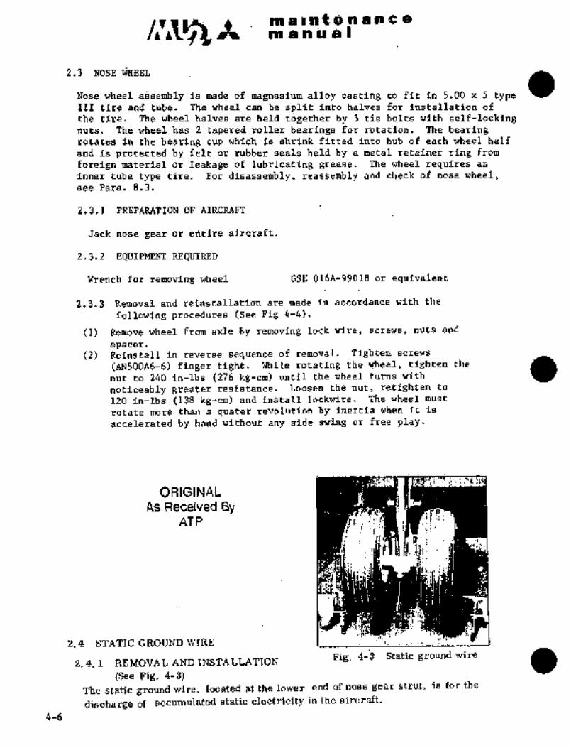
:iii a r a t ~cc,.-n iEj iDi a
in a n iai 3PI (I
2.3 NOSE WREn
Nose wi~eel asgemjDly i~i made of inagnesium alloy ccil~tilig to fit, iri 5.’b0 x 5 type;I‘II tire and tube. The wheel can be split into halves for ii~stallation of
the tife. The.wheel hal~ies are held t~gether by 3 tie bolt~ with sel~-lockingnuts. The wheel has 2 tapered.roller bearings for rdtation~ The bearingrotates in the bearing cup which is shrink fitted into hub o~ each wheel half
and is protected by felt or rubber seals held bya metal retainer ring from
foreign material or leakage of lubricating grease. The wheel requires an
inner tube type tire. For disassembly, reassembly and check of nose wheel,see Para. 8.3.
2.3.1 PREPARATION OF AIRCRAFT
Jack nose- gear or eritire aircraft.
2.3.2 EQUIPMENT REQUIRED
Wrench for removing ´•wheel GSE 016A-99018 or equivalent
2.3.3 Removal and reinstallation are made in accordance with the
following procedures (See Fig 4-4).
(1) Remove wheel from axle ~y removing lock wire, screws, nuts and
spacer.
(2) Reinstall in reverse sequence of removal~. Tighten screws
(AN500A6-6) finger t~ight. While rotating the.wheel, tighten the
nut to 240 in-lbs (276 kg-cm) until the wheel turns with
noticeably greater resistance. Loosen the nut, retighten to.
120 in-lbs (138 kg-cm) and Install lockwire. The wheel must
rotate more than a quater revolution by inertia iomen it is
accelerated by hand without any side swing or free play.
dh 1´•:
ORIGINAL
As Received By ne
AT PBR -k
2. 4 STATIC GROUND WIRE I I
Fig. 4-Q Static ground wire2. 4. 1 ’REMOVAL AND INSTALLATION
(See Fig. 4-3)
The -static ground~wire, located at the lower end of nose gear strut, is for the
discharge of accumulated static electricity in the aircraft.
4-6

c~A IPB ji~i ~i f (B a a a c a
ta~ ~a a a 8
When the giaund wire be~omes worn, t~e wire to propBr length, as
to give positive contact with the ruiii~ay.
2. 5 NOSE: LANDING GEAR STRUT (See Fig. 4-4)
3
12
z -1z
;1
12
13
12
13
21~ Tcl 1 ,8
~it ,15Ti6 i
13
1
I$i 19
12
.1 1513
Iq9 1611
9
I17
io
1. Bolt 9. Torquelink 18. Support
2. Body .10. Axle 19. Up-lock roller
3. Airvalve 11.Nut 20. MetRringpin
4. Centering roller 12; "0" ring 21. qiston
support 13. Back up ring -22. Straightener
5. Nut ´•14. Scraper
6. Shimmy damper 15. Radial bearing
7. Trunnion 16. Bearing cover
8. Cylinder 17. Thrust bearing
Fig. 4-4 ~Nose lanciing ge8rstrut
4-7

C~5 It ~nl a i at a a a a a a
m a a a a I
2; 5; 1 DISASSENIBLY AND REASSEMBLY
6ee~ Overhaul Manual (YET89148)
2. 5. i MAI~TENANCE
(1) Keep exposed strut piston clean by wiping with soft cloth moistened with
hydraulic fluid MIL-H-5606.
(2) Inflate strut ivSth Nr gas to 190rt 7 psig(l3. 3f 0.5 kg/cm2) with strut fully.extended or until H dimension and pressure conform with the followingchart withinfl5 psi. (1
CAUT)ON
When the temperature varies greatlyfrom the temperature at the timeof
last inflation, pressure and dimen-´•
sion "H" will not conform with the
chart. Reinflate strut to conform,with the chart.
700
D 500
91 400
rn 300 r- r I I 1 I I
g190 3t 7 sig
~i 200
~t too
2 3 4 5 6 7 8 9 10 11 12
HDIMENSION tin.1 I I 1 1 I I
~M) 70 90’ 110 180 150 170 190 210 280 250 no zoo 810
HDIMENSION (mm)
4-8
maintenanceman ual
TEIIIIP6RARY REVISIC)N N0.4-~This Temporary Revision No. 4-1 is applicable to the following Maintenance
Manuals
MODEL NO. REPORT NO. PAGE
MU-2B-35/-36A MR-0218 4-9
MU-2B-60 MR-0336 4-9
Insert facing the page indicated above for the applicable MaintenanceManual
Retain this Temporary Revision until such time as a permanent revision on
this subject is issued.
REASON To add a non destructive inspection for NLG trunnion.
ADD Paragraph 2.5.3 as follows.
2.5.3 Non Destructive Inspection for NLG Trunnion
NOTE
This inspection is required for Trunnion until replaced with improved
parts P/N 0104~-39190-19.
(1) Preparation
(a) Place aircraft on jacks.
(5) Remove the nose gear wheels.
(c) Remove the NLG strut assembly and the following parts from the trunnion.
Shimmy Damper
Trunnion Arm
Spring holder and Uplock Roller
NOTE
Record lengths or mark adjustable parts, such as Uplock Roller, so
they can be reinstalled in the same position to facilitate adjustment
and rigging procedures.
(2) Inspection
Inspect by Magnetic Flux Inspection or Fluorescent Penetrant Inspection method as
follows.
TEMPORARY REVISION NO. 4-1
Page 1/4
Oct. 31/2002

maintenancemanual
TEMPORARY REVISION N0.4ilB
~a) Remove paint and clean the entire surface from affected area of the part to be
inspected with Methyl Ethyl Ketone or equivalent. (Refer to Fig. 4-6A for inspection
area.)
NOTE
It may be necessary to remove trunnion for inspection.
CAUTION
Do not allow Methyl Ethyl Ketone to contact piston seal area.
(b) Inspect the specific areas on the trunnion to insure there are no indications of cracks
using with appropriate inspection procedure.
NOTE
Magnetic flux inspection must be made in accordance with
ASTM E 1444. Fluorescent penetrant inspection must be made in
accordance with ASTM E´•1417 Type I Method C.
RESULTS OF INSPECTION
PART NAME PART NUMBER
IF NO CRACK IS FOUND IF CRACK IS FOUND
SCRAP, REPLACEPART MAY BE REUSED
WITH NEW PART INTRUNNION 010A-39190-111-13 BUTMUSTBE INSPECTED
ACCORDANCE WITHAT 200 HR INTERVALS.
PARAGRAPH 2.5.3.(3).
NOTE
If cracks are found in the trunnion, notify Field Service Operations
Manager of Mitsubishi Heavy Industries America, Inc., of the
following items:
a. Aircraft Serial Number
b. NLG Strut Assembly Serial Number
c. Clarify NLG Strut Assembly Hours In Use
d. Part Number of Trunnion
TEMPORARY REVISION NO. 4-1
Page 2/4
Oct. 31/2002

maintenanceman ua(
TEMPORARY RIVISION N0.4-11(c) If no cracks are found and part is to be reused, apply one coat of zinc chromate
primer and one coat of aluminized lacquer.
(d) Repetitive inspection must be conducted at intervals not to exceed 200 flight hours in
accordance with para. (2).
(3) Replacement of Defective Part
If cracks are found, replace the trunnion with 010A-39190-19 trunnion.
NOTE
1. When the trunnion is replaced, new trunnion pins and drag strut
pins should be used.
2. If the trunnion is replaced with PIN 010A-39190-19, bearing
cover should be replaced with new type P/N 010A-39191-11
simultaneously.
3. The 010A-39190-19 trunnion does not require further repetitive
inspections.
(4) Reassembly
Reassemble NLG strut in the reverse order of removal procedures (Rec 2.5.3~1)(c)).
TEMPORARY REVISION NO. 4-1
Page 3/a
Oct. 31/2002

maintenancemanual
TEMPORARY REVISI~N N0.4-L~
A A
t 1B B
IDENTIFY WITH
VIBRATION MARKER
SECTION A-A
t+~´•´•-
SECTION B-B´•’´•t’"´•’’~ CRITICAL AREA OF INSPECTION
Fig. 4-6A 010A-39190-111-13 Trunnion inspection area
-bTEMPORARY REVISION NO. 4-1
Page 4/4
Oct. 31/2002

m al nt a 1a a $i’% a
To chlk~re fbr flui;dquantity in d~eo strlit or refill with fluid, perform as
fdll(iws: (See Fig. 4-4 and 4;5.)
(a) RemBve bleostiut from aircrat.Alr valve
(b) De~flate strut through air v8lve, andi/
remove valire; body and bolts.
r GNOTEFill strut with
~jo not loosen air valve bocijr unless gas I MIL-H-5606h3Tdraulic fluid
is completely bled through air valve,
(c) Set strut in the most compressed i up to the filler
f port when strutposition and hold irertically. Fill strut
is in the mostwith hydraulic fluid (MIL-H-5606)
compressedup to the filler port,
/i j It position and
(d) Extend strut to full length and I held.upright.
compress fully again and fill with fluid SupportFig. 4-5 Oleo strut
up to the lower end of ~the filler port.
(e) Repeat these steps two or three tiines.
(f) Install valve body with air valve and bolts into the oleo strut, then
put N2 gas through the valve up to a pressure of 190 psi (13.3 kg-cm2).
(g) Leave the strut for one hour, and check for gas and fluid leakage,
ORIGINAL
As Received ByAT P
IE$ TEMPOR~RYREVISION
that revises this page.4-9(10)
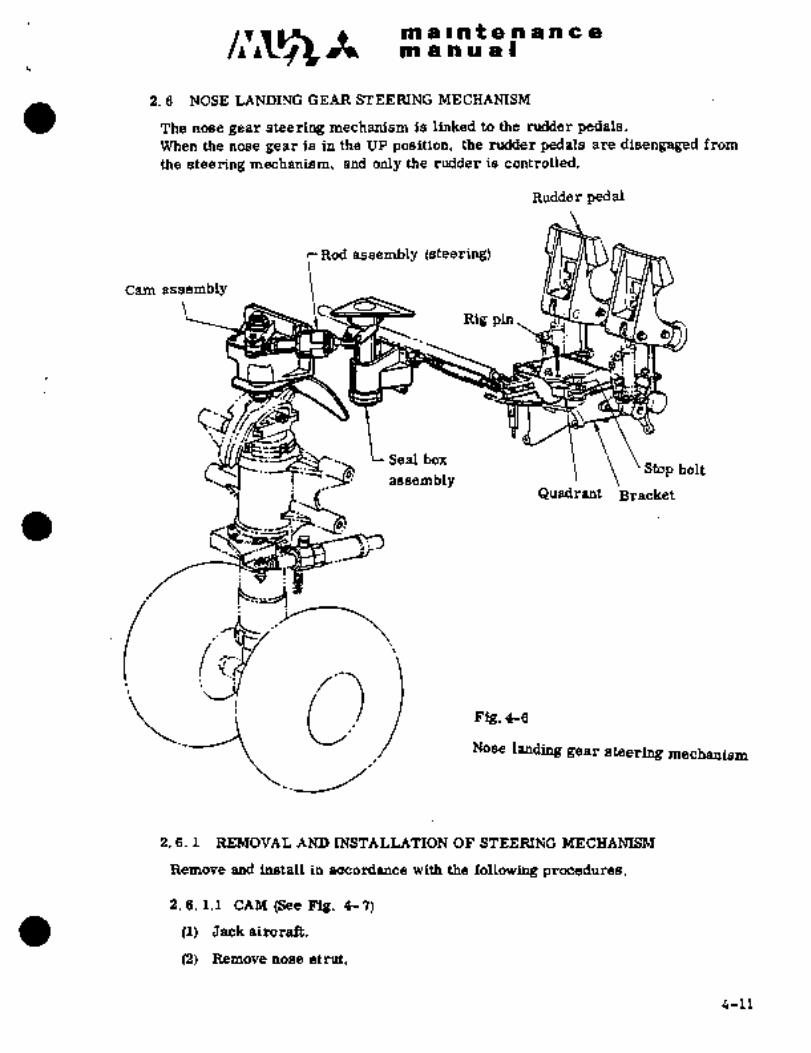
nl a Int a a a a a a
ni a a a at
2. 6 NOSE LANDING GEAR STEERING MECHANISM
The nose gear steering mechanism is linked to the rudder pedals.When the nose gear is in the UP position, the rudder pedals are disengaged from
the steering mechanism, and only the rudder is controlled.
Rudder pedal
Rod assembly (steering)
Cam assembly
.\~t3 Rig pin, Yt~,
lulTWn U4~e
Seal box
assembly’Stopbolt
,f~ Quadrant Bracket
olNose landing gear steering mechanism
2. 6. 1 REMOVAL AND INSTALLATION OF STEERING MECHANISM
Remove and install in accordance with the following procedures.
2. 6. 1.1 CAM (See Fig. 4- 7)
(1) Jack aircraft.
(2) Remove nose strut.
4-11
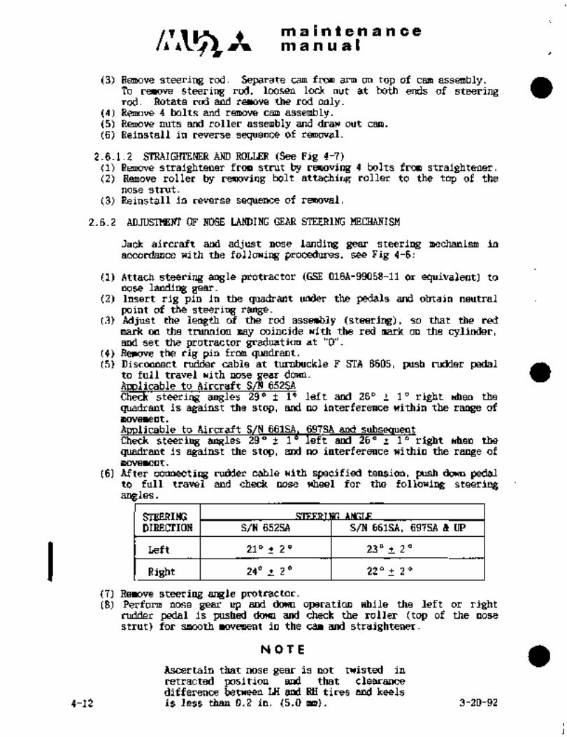
maintenancemanual
(3) Remove steering rod. Separate cam from arm on top of cam assembly.To remove steering rod, loosen lock nut at both ends of steeringrod. Rotate rod and remove the rod only.
(4) Remove 4 bolts and remove cam assembly.(5) Remove nuts and roller assembly and draw out cam.
(6) Reinstall in reverse sequence of removal.
2.6.1.2 STRAIG~ENER AND ROLLER (See Fig 4-7)(1) Remove straightener from strut by removing 4 bolts from straightener.(2) Remove roller by removing bolt attaching roller to the top of the
nose strut.
(3) Reinstall in reverse sequence of removal.
2.6.2 ADJUSTMENT OF NOSE LANDING GEAR STEERING MEMANISM
Jack aircraft and adjust nose landing gear steering mechanism in
accordance with the following procedures, see Fig 4-6:
(1) Attach steering angle protractor (GSE 016A-99058-11 or equivalent) to
nose landing gear.(2) Insert rig pin in the quadrant under the pedals and obtain neutral
point of the steering range.(3) Adjust the length of the rod assembly (steering), so that the red
mark on the trunnion may coincide with the red mark on the cylinder,and set the protractor graduation at "O".
(4) Remove the rig pin from quadrant.(5) Disconnect rudder cable at turnbuckle F STA 8605, push rudder pedal
to full travel with nose gear down.
Applicable to Aircraft S/N 652SA
Check steering angles 290 10 left and 260 10 right when the
quadrant is against the stop, and no interference within the range of
movement
Applicable to Aircraft S/N 661SA, 697SA and subsequentCheck steering angles 290 10 left and 260 10 right when the
quadrant is against the stop, and no interference within the range of
movement
(6) After connecting rudder cable with specified tension, push down pedalto full travel and check nose wheel for the following steeringangles
STEERINGDIRECTION S/N 652SA S/N 661SA, 697SA 8 UP
I Right 240 20 22 O 2 O
Left 210 _+ 2" 230 2"
(7) Remove steering angle protractor.(8) Perform nose gear up and down operation while the left or right
rudder pedal is pushed down.and check the roller (top of the nose
strut) for smooth movement in the cam and straightener.
NOTE
Ascertain that nose gear is not twisted in
retracted position and that clearancedifference between LH and RH tires and keels
4-12 is less than 0.2 in. (5.0 mm). 3-20-92

~in a ii.n f.~ H ;tii i~i i~ ;Qi
i;n b li~ ii a
OF CAR~ I4SSEMBLY (S~’e Fig 4 7)
(1) AdjuGt cain asseii~bly so that bite between centering roller and straightener
iiiay ~e dimerisio~ A in Piif. 4-.7 add biSo bite between steering roller and cam
may be dimension B,
(2) The steering roller should move smo~thly. alid meet dimension C in Fig. i~-’i
while the nose gear is steered´•to the right and leff iri down
locked pdsition.
(3) Exten~Z ndse gear with the wheel steered to full‘extent. The dimension D in
Fig. 4-j Shbuld be met whed the steer’irig roller c~mes in Contact ~lith the cam.
Adjusting plate r Shim (Record the
(Apply alignment number of shim
mark in vertical. I when removal)direction when
Bracketremoval)
Cam assemblyBolt
Cam,tSteering roller
A: 0.08f0.04 in.
Cente ring (2 f 1´• mm)~,´•B (Full range from L/Groller
down to up. iassembly
..´•1 B 0. 04- 0. 16 in.
(1--4 mm)(L/ G down position)
C 0. 08~0. 24 in.D (icv7 trim~
st~i"i 1 I/IYD More than O. 02in. (0. 5mm)
(Full range)
Fig. 4-7
2.7 SHIMMY DAMPER
2. 7. 1 REMOVAL AND INSTALLATION OF‘ SHIIMMY DAMPER
(See: Figs 4-8 ~and 4-9)
(1) Remove boltattaching shimmy ´•damper rod end.:i
(2) Remove bolt ct;nnedting shimrriy damper housing and nose Strut.
(3) Reinstall in severse selcluence of removal.
The following are check items of -installation:
.4-13

sja lie n e is n ~a ps E
m a ~s ru a s
Check bolts, nhts aad bushings for deformation and cracks,
~b) Tighten attaching bolt finger tight. install cotter pin.
adj~istmeot shim of suitable thicl~ness into the forward and
aft attaching points of shimmy damper to eliminate free play.
12 141~ 13 8
13i. 2 7 159 14 13
3 54 16 13 6 8 9 11 10
i. -Rod end 7. Wiper 13. "0" ring
2. Nut 8. Plug 14. Back up ring
3. Washer 9. Spring 15. Cap ´•seal
4. Lockwire 10. Retainer ring 16. Housing
5. Retainer ii. Spring retainer
6. Piston 12. Filler dap
Fig. 4-8 Shimmy damper assembly
2. 7. 2 DISASSEMBI;Y, AND REASSEMBLY OF SHIMMY DAMPER
For disassembly and reassembly of shimmy damper, see Overhaul Manual YET70058.
2.7.3 ADJUSTMENT OFSHIMMY DAMPER (See’Fig. 4-10
(1) Check shinrmy damper for fluid level
by inserting 0.04’in.(l mm) diameter
probe in the hole opposite to rod end.
If the probe is not allowed to enter
3.23 to3.35 in. (82 to 85 mm) deep,fill shirmny damper with fluid in ac-
cordance with the following procedures.
NOTE
The depth to which the probe is inserted
should be within 3.23 to 3.35´•in. (82~t685 nrm) just after reassembly of shinrmy
damper. While in servicing, the maximum
allowable depth is 3.94 in. (100 mm).Make adjustment if 3.94 in. (100 Ihm)~ is Fig. 4-9 Shifirmy damperexceeded
ORIGINAL4-14 As Received By
AT P

m jail afa tl h~ a a
ali a a ii a I
WIRE
Dimension "A" -.3.29 to 3.94 In´•´•
(83..6 to i00.~1 mm)
F’ig..4-lO ’:Adjustment of
shirmny damper
g
to
3. 0 3. 5
Dimension .in.
80 85 90
Dimension mm
Fig. 4- 1 1 Temperature-d imensidn
_ diagram
4-15

~3 ~t m a Int a -n a a a 8
nT ahu~l
(a) Remove shirmmv damper from nose gear.
(b)Insert through the hole and tighten into plug (Fig 4-8 Item 1).
Insert a screw assembly (Flg 4-12) into end opposite rod end.
Slide washer of screw assembly to shimmy damper housing and tightenthe nut against the washer until resistance is felt, which indi-
cates spring con~ression.(c) Remove filler cap.
NOT ii
Slowly and gently compress springin piston rod. Care must be taken
not to damage O-ring when removingfiller cap.
(d) Fill piston rod with actuating fluid MIL-H-5606.
(e) Install filler cap~and release spring compressed per Para. (b) above.
(f) Operate shinnnv damper by hand’ as quickly as possible. Check for
unusual resistance and no leakage. Fluid level check probe must be
freelyinserted to a depth of 3.23 to 3.35 in. (82 to 85 mm).
(g) Reinstall shinrmy damper to pose gear.
(2) Check shinrmv damper attaching point for any abnormal looseness.
Adjustment shouid be made per Para.. 2.7.1 (b) to eliminate free
play.If looseness is detected at rod ~nd side, replace the spacer (010A-39129-5) and adjust.
(3) Check shirrny damper attaching parts for proper lubrication,;
~1/4 x 28 x 40 Screw/Bolt
1/4 x 28 Nut
1/4 Steel Washer
Fig. 4-12 Screw assembly
4-16

A iin II nt;e.~H a n a,
in a a a II
NOSE LANDING GEAR Ui~ IND;ICATOR SW~TCH (See Fig 4-13)
fi.a.l REMOVPI~ AND INSTALLAT~ON OF NOSE LANDING GEAR UP INDICATOR SWITCH
~he nose landing gear up indicator switch is installed on the LH sidewall of
hose gear well atid is connected with "UNSAFE" indicating circuit tb indicate
nose gear in retracted positiori.
(1) Remove lower forward LH nose access panel.
iij Remove the pendulum which connects switch link and Lever
assembiji and detach switch link.
(3) Loosen the lock nut attaching the switch lever and remove the lever.
(4) Remove the nuts attachingthe switch´•and remove the switch.
(5) Install in reverse sequence of removal.
2.8.2 ADJUSTMENT OF NOSE LANDING GEAR UP INDICATOR SWITCH
After~installation of nose landing gear up indicator switch, adjustment should
be made in accordance with the procedures described in Para. 10.2.
i
~F:
F~lyd::--/ii
J/-I
i- j
Lever Assy_jSwitch
IHinge Lug.
J
Fig. 4-13 NoSe geaL up ’indicator switch
4-17

~a a In t a a a a a a
~ts a a a a I
2.9 NOSE LI1M)ING GEAR DOWN LOCK
2.9.1 ADJUSTMENT (See Fig 4-14 and 4-15)
(1) Adjust location of nose gear down lock limit switch (located on RH
keel, nose wheel)~ in accordance with procedures described in Para.
10.1, so that the switch may be actuated when down lock (LH side)of nose gear drag strut is placed in the groove more than 0.24 in.
(6 arm) deep with gear in down position.
(2) Check for a clearance of 0.002 to 0.012 in. (0.05 to 0.3´•rrrm) between
nose gear drag strut and drag strut pin (See Fig 4-2).
(3) With nose gear in down locked position, check downlock for more r
than 0.08 in. (2 rmn) clearance from the lock groove end at
RH side, more clearance at LH side.
(4) Perform nose gear retraction and extension under a load of 11 Ibs
(5 kgs) on the axle to the airplane nose direction. Adjust the
eccentric bolt on the LH drag strut so that the down lock maybe operated smoothly under the following conditions.
(a) No abnormal noise on down lock (LH) in gear retraction.
(b) The difference between LH and RH down lock engagements is
engage ingear extension.lessthan *0.12 in. (3 mm) when the down locks are´•about to
(5) Check for the following items in gear extension.
(a) Rh downlock engages *0 to 0.06 in’. (O to 1.5 mm) deeper;than LH downlock.
(b) The down lock has no interference with other parts up to
to the end of its travel.
When the difference between LH and EH exceeds the specifiedvalues, replace lock assembly with a new one.
4-18
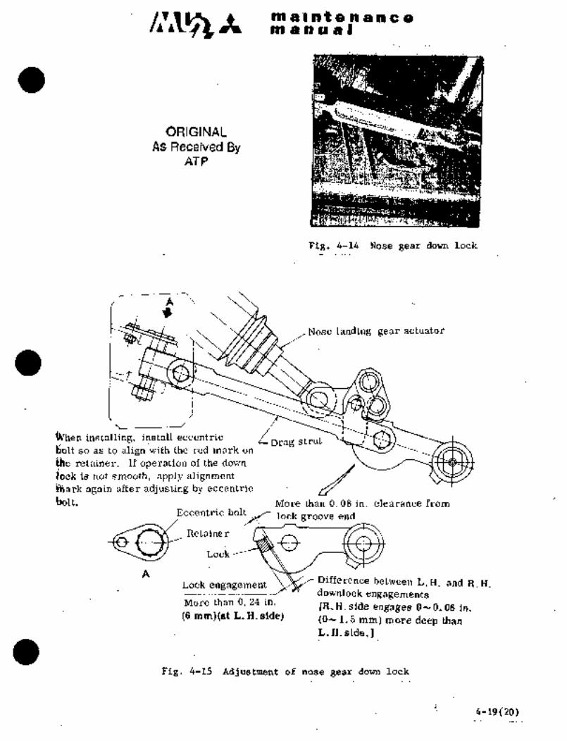
ir~i ~ci eis liiaIiEi ilB a: e
ORIGINALAs Received By
ATP
Fig. 4-14 Nose gear down l~ck
r:A
Nose landing gear actuator
1~U‘´•\) ilk-?F\12
I
installing, installeccentric iorag strutso as to align with the red mdrk dn
retainer. If operation of the dowh
iiijck is not smooth, apply alignment~ark again after adjusting by eccentric
I;blt, More than 0. 08 in. clearance fromEccentric bo~
lo~l_k groove end
Retaine
rI~ocic ;3:Lock engagement.
Difference between L.H. and R.B.downlock engagements
More than 0. 24 in. IR.H. side~ engages O- 0. 06 in.(6 mm)(at ´•L. H.side) (0-1.S mm) more deep than
L.H.side.]
Fig. 4-15kdjustment ofnosegear downlock
i-19(20)~

:im alntenance::;~nl a a a a I
2. 10 NOSE LANDING GEAR DOOR MI’:Cf-IANISM (See Figs. 4-16 and 4-17)
’I~he nose landing Real’ door nluchnnism is opcrnlcd by up or down movements of
nose gear strut. The sliding surface of the bw~gce spring and the contact surface
of the strut should be kept free of dust and foreign objects at all times.
2. 10. 1 REMOVAL AND INSTALLATION OFNOSE LANDING GEAR DOOR
MECHANISM
(1) Remove rods (L. H. and R. I-I. connecting to the nose landing gear doors.
(2) Remove bolts (L. If. and R. Ii. connecting the Llirframe filling and arm.
Remove door niechanism.
(3) Install in reverse sequence of removal.
B
.i, Bungce spring
A
f rB’
Stop bolt _~
Cam Adj usting rod
C’ 0. 04 0. 16 in.
(1--4 mm)
Fig. 4-16 Adjustment of nose geardoor mechanism
2. 10. 2 ADJUSTMENT OF NOSE LANDING GEAR DOOR MECHANISM
(1) With the nose gear down and lacked, adjust the stop bolt so that the
arm touches the stop bolt when point A comes to point A’ as illustrated
in Fig. 4-16 and 4-17 and make sure that the point A may overcenter the
line B-B’. After tightening thenuton thestop bolt, apply alignmentmark.
4-21

maintenancemanual
,I
i. Bungee spring2. Arm
3. Adjusting rod
4. Stop bolt j /35. Door I
B~----
0. 041´•0. 16 in.~1´•v4 mm) whe
point A comes to
point A’
~g. 4-17 Nose gear door
(2) When the point A falls on the line B B’, adjust the cam so that the end of
the jaw may be located 0. 04~ 0. 16 in. (1-- 4 mm) away from the nose strut.
(3) Adjust the rod so that clearance between the doors and tire may be not less
than 1. 2 in. (30. 5 mm) when the doors are open and not less than 0. 8 in.
(20. 3 mm) when the doors are closed.
(4) Retract the nose gear till the clearance of the mechanical stop becomes
zero. Hang a weight of 20 Ibs (9 kg) on the center edge of each forward
door and make sure that the doors come off the door jambs 0.39 to 0.59in. (10 to 15 mm). Adjust the rod length if necessary.
(5) The distance between LH and RH nose landing gear door at the rear-
lower end, should be more than 18in at the gear down condition.
(See Fig 4-17t´•i) (S/N 697 and up)
4-22 4-30-87

CIV42maintenancemanual
C’
18in. and up
Fig. 4-17A. Adjustment of Nose Landing Gear Door
2. 11 TORQUE LINK ASSEMBLY (See Fig 4-18)
The handle assemblies which are flble to disconnect upper and lower torque links
are installed on torque link nssembly.In towing, the upper and lower links shall be disconnected.
2. 11. 1 REMOVA L AND INSTA LLATION
(1) Pull out L. Il.. ancl R, H. handles and disconnect upper and lower torque linlts.
(2) Remove attaching bolt of upper link, pull out pin and remove upper link from
airplane.
4-22-14-30-87

i e ri a n c cim d’n is a I
(g) Remove bb~t of lower pull out pin and remove lower link
frbin airplane.
(4) 4’ff safetjr wire an remove handle assembly from the removed upper
1 ink.
(5~ Reinstall in reverse sequence of removal.
i"f-g:gj´•: ~t- j ‘l----=_______L____ ‘´•j
o
Handle
Fig. 4-18 Nosegear torque link assembly
2. 12 MAINTENA.NCE OI: NOSE LANDING GEAR
(1) For maintenance of oleo strut, perform per Pars. 2. 5. 2.
(2! Keep shimmy damper piston rod clean by wiping with soft cloth moistened
withhydraulic fluid MIL-I-I-iSGOG.
(3) Check quantity of hydraulic ~fluid in shimmy damper.When fluid is insufficient, refill fluid in accordance with procetlures given in
Para. 2. .3.
When there is any´• evidence of air mixed in. fluid, disassemble and refill
with hydraulic fluid.:
ORIGINAL
As Received ByAT P
4-23
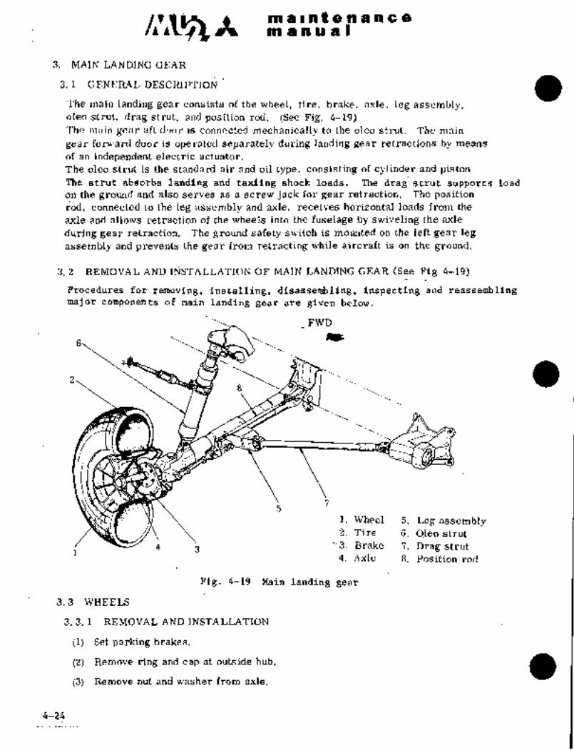
xmalnite 018ne a
m a a a a
3. MAIN LANDING GEAR
3. 1 GENERAL DESCRIPTION
The main landing gear consists of the wheel, tire, brake, axle, leg assembly,oleo strut, drag strut, and position rod. (See Fig. 4-19)7’ho ,n:tin Kc;"r uft door is connected mechanically to the oleo strut. The main
gear forward door is operated separately during landing gear retractions by means
of an independent electric actuator:
The oleo Strut is the standard air and oil type, consisting of cylinder and piston.The strut absorbs landing and taxiing shock loads. The drag strut supports load
on the ground and also serves as a Screw jack for gear retraction. The position
rod, connected to the leg assembly and axle, receives horizontal loads from the
axle and allows retraction of the wheels into the fuselage by swiveling the axle
during gear retraction. The ground safety switch is mounted ~on the left gear leg
assembly and prevents the gear from retracting while aircraft is on the ground.
3. 2 REMOVAL AND I~jSTALLATION OF MAIN LANDING GEAR (See’ Pig 4-19)
Procedures for removing, installing, disassemb~ing, inspecting and reassemblingmajor components of main landing- gear are given below.
FWD
a
i. Wheel 5. Leg assembly2. Tire 6. Qleo strut
4 j ’3. Brake 7. Drag strut
4. Axle 8, Position rod
Fig; 4-19 Main landing gear
3. 3 WHEELS
3. 3. 1 REMOVAL AND INSTALLATION
(1) Set parking brakes.
(2) Remove ring and cap at outside hub.
(3) Remove nut and washer from axle.
4-24
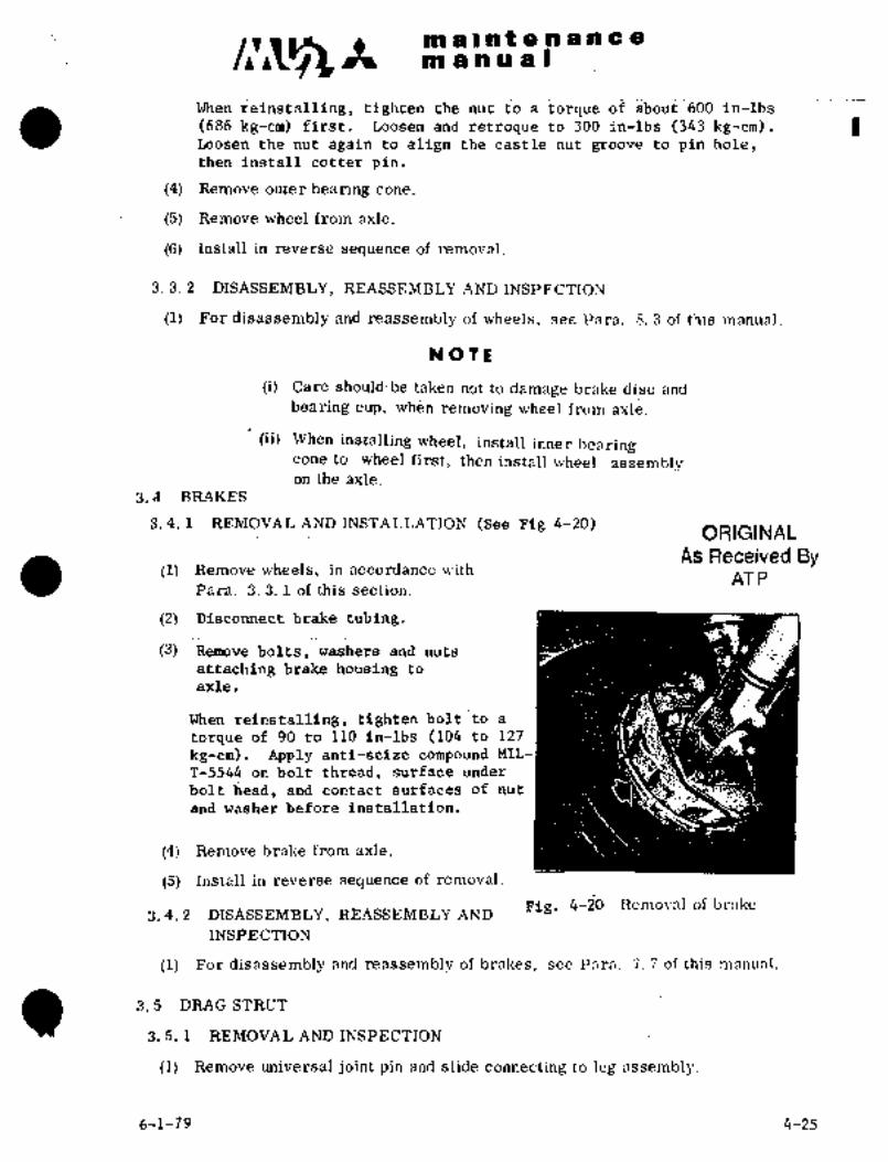
CI1~~n a’ls in t a a a a a a
m a a or a B
When reinstalling, tighten the nutto a torque of about 600 in-lbs
Loosen the nut again to align the castle nut groove to pin hole,Loosenandretroque to300 in-lbs (343 kg-cm),(686 kg-cm) first.
then install cotter pin.
(4) Remove outer bearing cone.
(5) Remove wheel from axle.
(6) Install in reverse sequence of removal.
´•3. 3.2 DISASSEMBLY, REASSEMBLY AND INSPECTION
(1) For disassembly and reassembly of wheels, see Para. 8. 3 of this manual.
Na T.~
(i):. Care should be taken not to damage brake dise andbearing cup, ´•when removing wheel from axle.
(ii) When installing wheel, install inner bearingcone to wheel first, ~then install wheel assemblyon the axle.
3; A BRAKES
3.4.1 ~EMOVALAND INSTALLATION (See Fig 4-20)ORIGINAL
As Received ByII) Remove wheels, in accordance with
AT PPara. 3. 3. 1 of this section.
(2) Disconnect brake tubing,
(3) Remove bolts, washers and nuts
attaching brake housing~ to
axle,
When reinstalling, tighten boltto a
torque of 90 to 110 in-lbs. (104 to 127
kgicm), Apply anti-seize compound MIL-
T-5544 on bolt thread, surface under
bolt l;ead, ´•and contact surfacesof nut
and washer´•.b.efore installation.
(4) Remove brake from axle.
(5) Install’in reverse´• sequence of removal.
Fig, 4-20 Removal of brnke3. 4. 2 DISASSEMBLY, REASSEMBLY AND
INSPECTION
(1) For disassemhly and reassembly of brakes, Isee Pnra. 7_ 7 of tliis manual.
(I) 3. 5 DRAG STRUT
3. 5. 1 REMOVAL AND INS6ECTION
(1) Remove universal joint pin and slide connecting to leg,2ssembly.
6-1-79 4-25

m a a f a a a a a a
m anual
(2) Remove unilersal jointpin and slide connecting to bos ;~n(l st
support.
in, ncmove drag strut from aircraft.
(´•2) in reverse sequence of removal. When installing, adjust universal
joint washer and nut to be concentric and tighten.
NoTL
Pzefore removing´•drag strut, measuring and
recording length of screw protruding from barrel
M;ill facilit’ate reinstallation.
:1. 5~ ’2 DISASSEMI~LY, INSPECTION AND REASSEMBLY OF MAIN LANDING
GEAR DRAG STRUT (See~ Fig 4-21)
UISA SS L;1L1B LY
(1) After removing drag strut from aircraft, rotate rod by hand and take rod
out of barrel.
(I~) Remove lock screw from b’arrel.
notate and remove support and ring.
INSPECTION
(L) Wash 311 parts in cleaning solution (Federal Specification P-D-680).
(2) Check acme thread carefully for wear.
I j
i. Barrel 42. Lock Screw
3. Suppor t5
4. Ring5. Rod
ae
6. Lock wirePig. 4-21 Main gear drag strut assembly
(3) Fit support in rod. Check for play in axial direction. Play shall
not exceed 0.018 in. (0.46 mm) foroverall thread section.
4-26

~5A maintenancemanual
(4) Inspect rod thread surface for condition of lubricant. Apply Molycoeeif necessary.
NOTE
It is not necessary to replace rod, even if lubricatingfilm is broken on the.surface of thread section of rod.
MIL-G-21164 Molycote grease is usually applied to
the thread for lubrication at 100 hour intervals.
Apply Molycote grease by hand as necessary depend-
ing upon conditions on the surface of thread section.
3.5.2.3 REASSEMBLY
(1) Apply Molycote grease (MIL-G-21L64) on the inner surface of support.
(2) Apply MIL-G-21164 grease to threaded portion of rod and screw rod
into barrel.
(3) Screw in support and ring and install two lock screws. Apply lockwire.
(4) Assemble universal joint and connect to gear box and drag strut support,and leg assembly. Tighten nut and install new cotter pin.
NOTE
(i) Attaching bolt on the leg assembly side should be
installed with its head on the inner side of airplane.
(ii) When ring is replaced with new one, make a drillhole of ~21(4.04 mm dia.) from lock screw holeon the barrel to ring side after installing supportand ring onto the barrel, and cut a thread of #10-32NF-3B. Reassemble in accordance with the above
procedures.
3.6 OLEO STRUT (Fig 4-22)
3.9.1 REMOVAL AND INSTALLATION
(1) Disconnect rod that links main gear forward door and oleo strut.
(2) Retract main gear‘half-way and remove cotter pin from upper connectingbolt of oleo strut.
(3) Extend main gear and remove upper universal joint of oleo strut and
lower connecting bolts of leg assembly. For installtion, tighten upper and
lower connecting bolts hand tight, and install cotter pin.(4) Remove oleo strut from aircraft.
(5) Install in reverse sequence of removal.
NOTE
Before removing oleo strut, place axle of legassembly on a stand. Care should be taken not to
damage leg assembly.
4-27

maintenancemanual
::I iz
12 a
3
10
13
3
14
1115
i. Air valve 5. Nut 9. Ring 13. Cylinder2. Upper fitting 6. Scraper 10. Piston ass’y 14. Meteringpin3. Backup ring 7. Felt 11. Shim 15. Lower fitting4. O ring 8. Bearing 12. Retainer ring
At assembly, adjust relation of cylinder and lower fitting by shims.Standard thickness of shims is 0.014 in. (0.36 mm).
Fig.4-22 Main gear oleo strur
3.6.2 DISASSEMBLY, INSPECTION AND REASSEMBLY
This work should be done at the authorized repair facility. Confer
with Beech Aircraft Corporation for more detail information.
3.6.3 MAINTENANCE
(1) Keep exposed piston rod clean by wiping it with a soft cloth
moistened with hydraulic fluid. (MIL-H-5606)(2) Inflate strut with N, gas to 510 7 psi (35.7 0.5 kg-~cm")(*l),
669 7 psi (46.8 0.5 kg-cm") with strut fully extended or untildimension "H" and pressure conforms with the following chart within
20 psi (1.4 kg-~cm’).
4-28 3-31-90

maintenancemanual
I´•´•´•´•la~7CAUTION
When the temperature varies greatly from the tempera-ture at the time of last inflation, pressure anddimension "H" will not conform with the chart.
Reinflate strut to conform with the chart.
"1 For oleo strut 030A-38151-11*2 For oleo strut 030A-38151-21
3-31-90 4-28-1/4-28-2

~n i ii~ ;f a a a a a am b’n ri a I
,3000
Pc Air25b0 valve
20001 ;I 1
Cil ´•cj 8a
8´• a
vl1500
a~_a
C3C1000 r I I I‘ ~Je ´•I I
1
~11669 zt 7 psi ´•k2m
I500
510~ 7 psi jfl
1´• ´•2´• 3 4 5’ ´•6 7 8 9 10 in.
20 40 60. 80 100.´•120140160-~80. 200. i20.2;40 260 mm
H DIMENSION
(3) If necessary, check strutfor fluid ´•levelin accordance with the followingprocedures.(a) Remove oleo strut.
(b) Bleed gasthroughair valve. Remove valve.
NOTEDo´•not loosen ~air’talv boil~l until.gas is completelybled from air´•.v8lve.
(c) Place o!eo strut infiilly´•compressed position. Fill strut held uprightwith fluidMIL-H-5606´• through filler port.
(d) Extend strut to full.length and return to fully compressed position.Fill strut with -fluid.
(e) Repeat these steps two or three times.
if) ~Reinstall airvalve.. Installoleo strut on aircraft. Apply
N gas pressure of 510 psi (~tl), 669psi. ("2) through air valve.
(6) Leave the strut for;one hour:; nd
check for gas´• and’ fluid Icaka~c.
"1 For loleo strut-030~38151-11*2 For oleo strll-t 030A-38151-21
4-29
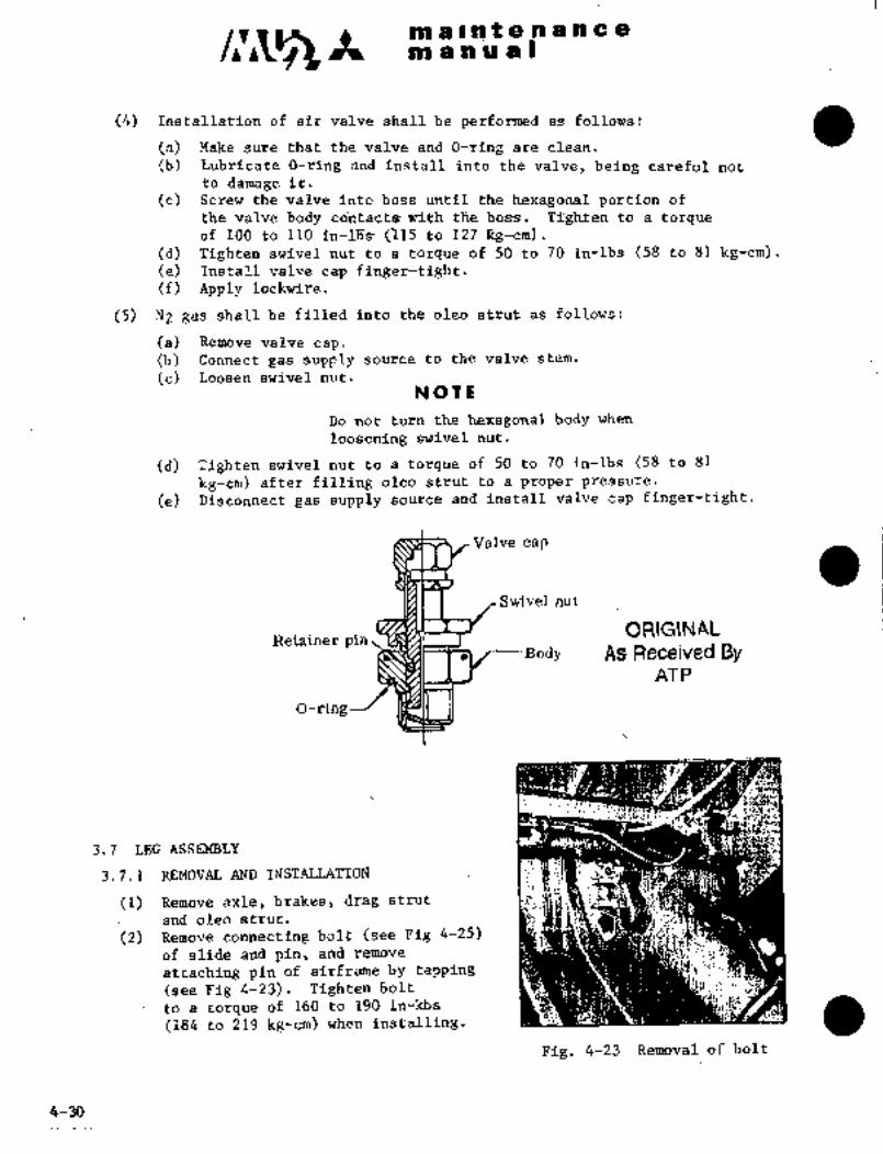
c~a m a I illt a 91 a a a a
fi~i a a W a i
(4) Installation of air valve shall be performed as follows:
(a) Make sure that the valve and O-~ing are clean.
(b) lubricate O-rin~ and install into the valve, being careful not
to damage it.
(c) Scre~w the valve into boss until the hexagonal portion of
the valve Tjody´• cdntacts with the lioss´•. Tighten to a torqueof 100 to 110 in-16s 015 to 127 lig-cm)l.
(d) Tighten swivel nut to a torque of 50 to 70 in-lbs (58 to 81 kg-cm).Ce) Install valve cap finger-tight.(f) Apply lockwire.
(5) NZ gas shall be ´•filled into the oleo strut as follows:
(a) Remove valve cap.
(b) Connect gas supply source to the valve stern.
(c) Loosen swivel nut.
NOTli
Do not turn the hexagonal bddy when
loosening swivel nut.
(d) Tighten swivel nut to a torque of 50 to 70 in-lbs (58 to 81
kg-cm) after filling oleo strut to a proper pressure.
(e) Disconnect gas supply source and install valve cap finger-tight.
Valve cap
Svlivel nut
ORIGINALRetainer pin
J--Body AS Received ByAT P
O-ring
’n~:::Xdi´• 1.
3.7 LEG ASSEMBLY
3.7. i-REMOVAL AND INSTALLATTON
Remove axle, brakes, drag strut
and oleo strut.
(2) Remove connecting bolt (see Fig 4-25)
of slide and pin, and remove
attaching pin of airframe by tapping
(see Fig 4-23). Tighten ~blt
to a torque of 160 to 190 in-kbs(184to 219 kg-cm) when installing.
Fig. 4-23 Removal of bolt
4-30

/I’~ ´•tmaintenance
man ual
(3) Remove leg assembly with position rod slide and axle attached;
(4) Install in reverse sequence of removal.
3.8 INSTALLATION AND INSPECTION OF MAIN LANDING GEAR (See Fig. 4-24, 4-25)
(1) Check bolts, washers, nuts and pins for distortion and cracks.
(2) When installing pins a.nd bolts, lubricate all parts which requirelubrication.
(3) Adjust drag strut length to the same dimension as that measured at the
time of removal.
(4) With main gear in extended position (drag strut thread length 0.67 to
0.98 in. (17 to 25 mm), adjust clearance "B" in Fig.4-25 to 0.012
a 0.004 in. (0.3+ 0.1 mm) when oleo strut is fully extended.
NOTE
Do not retract main gear before completion of the
adjustment described in Para.(4) above.
(5) Adjust position rod length as follows.
(a) Lift the aircraft on jack and level it horizontally.(See MU-2 STRUCTURAL REPAIR MANUAL YET-72035, Section 1, Para.3.3)
(b) Suspend weight from the specified point of the aircraft and draw
the center line of the aircraft at the longitudinal on the ground.
(c) Set moving nut of mechanical stop so that is comes in contact with
the mechanical stop at gear down position. By hand, adjust the
barrel of the main landing gear drag strut assembly to rotate
downward. Confirm that the drag strut length is 0.69+ 0.04 in.
(17.4 almm).
(d) Temporarily set the position rod length to the dimension shown in
Fig.4-24
(e) Confirm that center line of lower position rod and leg center crank
is within 0.02 in.(0.5 mm). If it is more than 0.02 in.(0.5 mm),adjust length of the upper position rod.
(f) Position a one (1) meter ruler inside the wheel and suspend weightsat both ends of the ruler(or set the GSE 030A-99011 to the wheel
boss and suspend weights one (1) meter apart). Project a shadow of
the weight on the ground and adjust the length of lower position rod
as the slope of wheel is 0.67in.(17 mm) to 0.87 in.(22 mm) tow-out
for39.37 in.(1000 mm) length on judgement in the different distance
between the shadow and the center line of aircraft axis.
5-2-94 4-31

maintenancemanual
(g) Confirm that center line of lower position rod and leg center crank
is within 0.02 in.(0.5 mm) as shown in Fig.4-24. If it is more
than 0.02 in.(0.5 mm), adjust the length of upper position rod and
accomplish adjustment from step (f).
(h) Adjust lower and upper position rod end bearings so they do not
hang up on main gear retraction and extension lugs.
17. 28 (Refe rence)9. 43 f 0. 02
(Temporary) ZUpper position rod
C’ I
A
A Leg center crank
LLower position rodC--- ~B
Apply mating mark on places marked with
0.020 in
39´• 37Point A should be on a straight line
io.~1001)
between B and C within 0. 020 in.
F. STA 1435 F. STA 8880
.Noc~
ForwardlCD--~
90"Center axial line
t~0. 6’lh´•0. 87 in.(17--22 mm)
Fig. 4-24 Adjustment of position rod length
4-32 5-2-94

maintenancemanual
NOTE
If adjustment is accomplished on this configuration,aircraft is 0 through 5/1000 tow-in condition with max
take-off weight with aircraft on ground.
After completion of the above adjustments, make sure that
upper and lower rod lengths are within the followinglimits.
Lower rod length dimension in Fig.4-24 ~0.04 in. (+1 mm)
Upper rod length dimension in Fig.4-24 f0.12 in. (+3 mm)
(6) Make sure that clearance "6" in Fig.4-25 is 0.02 to 0.04 in. (0.5 to
1 mm) with main gear in retracted position (drag strut thread length17.64t 0.04 in. (448f 1 mm)). If necessary, adjust by scrapingphenolic pad.
LI C~nnecting bolt
of slide and pin
Q i
jl U
r´•;
Fig. 4-25
5-2-94 4-33

/1~3A m a I´•n.:~ a .81 a na e.´• I-
m a a a al
3. 9 MAIN LANDING GEAR DOOR MECHANISM
The L. H. and R. H. main landing gear doors are composed of forward and aft
doors. The aft doors are connected mechanically with the main gear oleo strut
and operated with the landing gear. The forward doors are opened before and
closed after gear operation by an electric actuator. The fonvard door mechanism
is connected mechanically to the main gear aft door lock mechanism which is
unlocked when the forward doors open.
3. 9. 1 MAIN LANDING GEAR AFT DOOR MECHANISM (See Fig 4-26)
The main landing gear aft door mechanism consists of a rod having rod ends on
both ends and a spring in center. One end of the rod is connected to main gear
oleo strut and the other end to main gear aft door. Its length can be adjusted by
means of rod ends.
The lock mechanism is operated together with the forward door mechanism, and
also operated by emergency gear extension handle.
3. 9. 1. 1 ADJUSTMENT OF MAIN LANDING GEAR AFT DOOR MECHANISM
Adjustment should be made by moving gear up and down slowly with no load
and no inertia.
(1) Jack airplane.
(2) Adjust rod length so that the dimension "A" in Fig. 4-26 may
be 0.40 to 0.44 in. (10 to 11 mm) when up side nut of power
train mechanical stop reaches the end of its travel.
Main landing gear
aft door
Oleo strut
Emergency release cable
a, Rod detail
See Fig. 4-38 A
Rod end ,Rod rSpring!l ´•e Rod end
1 01 O
Fig. 4-26 Main landing gear door mechanism
4-34

iiP $I i;;lB f if ii ~P Q~i ~iiDi~P 10liU;i~(
~32 Undei- the cbnditi(jlis of Para. (2) above, check forthe clearancebet~we´•en m~in landing gea’r forwafd and art doo~s. The ciealrainCes~all be 0.08 f´•d.02 in. (2 f 0.5 mm) at upper edge and O.i~ f0.02 iii. (4 O,~ mm) at lower edge. (The cle~2racce between
up~er and lower edge~ changes alniost line8i-ly.) If necessary,trim again (See Fig 4-2r/).
main gear fhiii"f~llowlng It.ems:(4)
(a) The switch actliates at the position where mechanical z~top nut is less
than 0. 3’2 in. away from the end of its travel.
o. 08 f 0; 02 in.
(2+0.’5 mm)
Forward dobr
Aft door
O. 1G f O. 02.in.
(4f0.5 mm)
Fig. 4-27 Clearance between forward and aft doors
ib) With landing gear retracted, the forward door closed.and the a~t door
loaded,the "UNSAFEI’ light must not come on until the door hook
strikes the rolle r.
(5) Checkby moving the aft door for the clearance between the aft door
roller and hook tip as shown in the following figure.
Hook
Roller
0. 12N 0. 24 in. (3 to 6 mm)
4-35
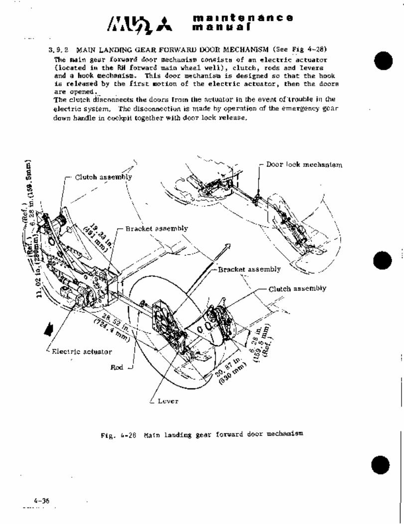
m a Inaensncem anual
3. 9. 2 MAIN LANDING GEAR FORWARD DOOR MECHANISM (See Fig 4-28)
The main gear forward door mechanism consists of an electric actuator
(located in the RH forward main wheel well), clutch, rods and levers
and a hook mechanism. This door mechanism is designed so that the hook
is released by the first motion of the electric actuator, then the doors
are opened.The clutch disconnects the ~oors from the actuator in the event of.trouble in the
electric system. The disconnection is made by operation of the emergency gear
down handle in cockpit together with door lock release.
a r Door lock mechanism
r Clutch assemi;;/y
IHoOQ)c~
i,
fs´•’9 Bracket assembly’.33
~a\ ´•1Bracket assembly
cuoClutch assembly
10.~ ´•g
98,Cu"3~´•’
Electric actuator
Rod 8~
Lever
Fig. 4-28 Main landing gear forward door mechanism
4-36

a ~:rrt a a a ti a a
sti rii Ir~ Si is I
(jF LANj3IEjG GEkR FORI~ARD DOOk
(1) D6or closed and locked conditiori (Sei~ Fi~ 4-29).
Short
i rodLink ’Y A/
Link
I A:mRod
cii~
Actuator hook ;Iq-
Torque~be Link
ass’y
ctuator Forward door
Linkass’y
Lever
ookRod
Crank ass’y
rC
_t.~e
Operated together with7 Forwarddoor
aft door operating mechani
Fig. 4-29 Main ’.-forvard’ door closed and Locked..condition
4-37

m a II at a a a a a a
ah a a a a I
(2) Door opening (See Figs 4-30 and 4-31).
(a) When electric actuator actuates, the actuator shaft extends to the arm
side, the direction of the arrow. The other link assembly side is fixed,because the door is still locked.
~j) Arm, link, torque tube, lever, rod and lock hook move or rotate to the
direction of arrow respectively and lock is released. Then, actuator
lock hook becomes free, because the door is opened slightly.
(c) The door is pulled to the open side furthermore by air pressure, so
actuator which is connectRd with the door, moves outboard ´•slightly and
actuator lock hook is locked. (actuator locked condition.
NOtE
When R. H. door lock is released earlier than L.H,actuator may be locked before L. H. door lock is
released. In this case, actuator shaft continues to
extendwith L. H. door in locked condition, so shear
pin ~will be sheared off.
Therefore, adjustment must be made so that L.H.
door rock may be~ released earlier than R.H. side.
(See Pare. 3.9.2. 3)
(d)´•´• Due to actuator lock, arm side of actuator shaft is fixed and actuator
shaft extends to the link assembly side only in the opposite direction of
Pare. (a),
(e) Link assemblies, rod assembly and short rod, etc., move´•or
to the direction of arrow and door is opened.
(f) When door is about fully opened, operationf electric actuator is
stopped by limit switch and door opening is stopped.
(3) Door closing
Door closing is made in reverse sequence of door opening.
4-38

CIViS I~R;it i iil/f d hi iC ~igi~ol g pli i~ a I
an’
9/
~li- ~Y
1_7
Fig. 4;30 Main landing gear forwarh door lock released condition
4-39
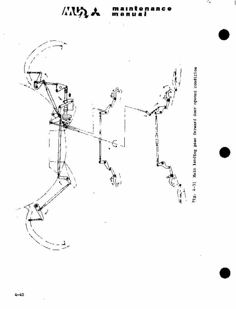
malnfenancem anual
O
isI Ijj
iTio Ir,
ii7 6"i
i C‘-I Ir-- I ~j
i iiI ’I -~p_i M
CC
2 ,i It
ikl
6-60
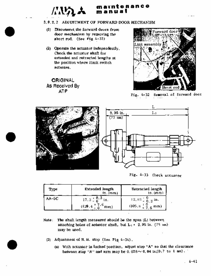
clr~sm a’I~n t a a a a a a
m an a a I
3. 9. 2. 2 ADJUSTMENT OF FORWARD DOOR MECHANISM
(1) Disconnect the forward doors from
door mechanism by removing theFonva~d door
short rod. (See Fig 4-32)
L’ink assembl
(2) Qperate the actuator independently.Check the actuator shaft for
extended and:retracted lengths at Isp~´•l a
the position where limit switch
actuates.
ORIGINAL
As Received By :IAT P
Fig, 4-32 Removal of forward door
2. 95 in., L11
r(75nm
Fig, 4-33 Check actuator
Type Extended length Retracted lengthi"´• (mmt in. (mm)
AA-SC 0. 3 t- 017.3
_ O i". L2. O3_ 0, 3
in’
7;6 0(439.4_ 0
(305. 6 mm)7.6
Note: The shaft -length measured should be the span (L) bet~een
attaching holes of actuator shaft, but L1+ 2. 95 in. (75 mm)
maybe used.
(3) Adjustment of R. H. stop (See Fig 4-34),
(a) With actuator in locked position, adjust stop"A" so that the clearance
bet;veen stop 1A" and arm may be 0. 028" 0. 04 in19.7 to 1 mm).
4-41
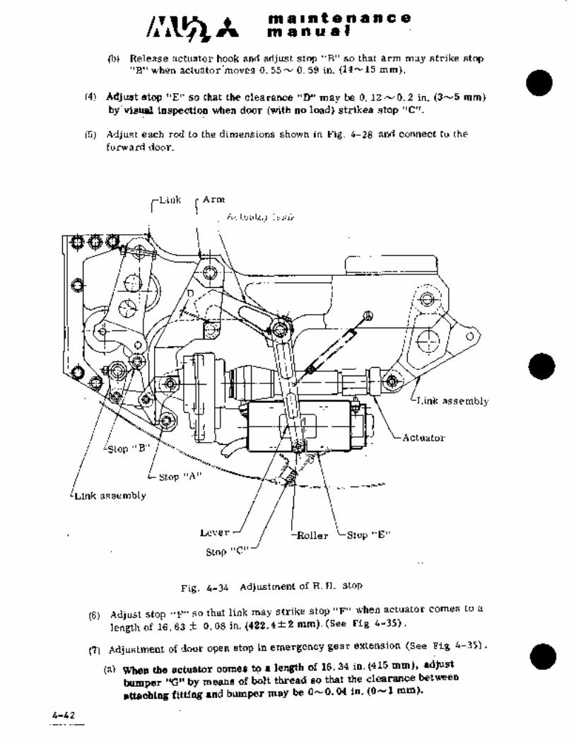
~5A malhf8nance222 a a a a I
(b) Release actuator hook and adjust stop "B" so that arm may strike stop"B’’ when actuator’moves 0. 55 N 0. 59 in. (14~v15 mm).
(4) AdflL9t stop "E" so that the clearance "D" may be 0. 12 N 0. 2 in. (3´•v5 mm)
by’visual inspection when door (with no load) strikes stop "C’).
(5) Adjust each rod to the dimensions shown in Fig. 4-28 and connect to the
forward door.
/Link rArmEtc;f.Ua.l6il’ j´•l~iOL
P k-Tz~-:
O
Link assembly
Stop "B"
Stop "A"
r
Actuator
Link assembly
Lever LRoller Stop "E"
Stop "C"
Fig. 4-34 Adjustment of R.´•H. stop
(6) Adjust stop "F" so that link may strike stop "F" when actuator comes to a
length of~16. 63 f 0. 08 in. (422.4f 2 mm)l(See Fig 4-35).
(7) Adjustment of door open stop in emergency gear extension (See Fig 4-35).
(a) When the actuator comes to a length of 16. 34 in. (415 mm), adjust
bumper 1(G" by means of bolt thread so that the clearance between
atta~iing fitting and bumper may be 0--0. 04 in. (ON1 mm).
4-42

C;C~gin ri I nt’cia a a a a -e
ni’ra;n a a I
(8) Check main landing gear; for interference.
(a) Check for interference between door mechanism and airframe
structure when adjusting in Para. (6).
(b) Check for interference between door attaching pdint and door tuhen
adjusting in Para, (6).
(9) Adjust fo~ard dobr open limit switch by means of nut,so that ther;troke ofL,H,limit s~Titch may be 0.08 to 0.10 in, (2´•to 2.5nrm),when actuator length is 16.34 in. (415 mm) (See Fig 4-68),
~10) Adjust limit switch so that the stroke of the switch may be 0. 16 0. 20 in.
(41;5 mm) when-the door strikes the stop.
Bumper ’’G’’
O-YO~ 04 in. i011 mm 0.1~812O ’n´• (4-5mm
~-Limit switcho Attaching fitting
.Q Link assembly
RodCLink
Rod
Stop’lF"Fig, 4-35 Adjustment of stop Fig, 4-36 AdJustment´• of limit switch
3,9. 2.3 ADJUSTMENT OF MAIN LANDING GEAR DOOR I;Oi=K~(See Figs4-37 and 4-38).
The door lock ~mechanism consists of.forward door locli mechanism and aft door
lock mechanism. Each lock is released before door operation.
(1) Adjustment of door side roller
Under the conditions thatthe doors strike thedoor stopsand the hook comes
in contact with stop, adjust the´• attaching fitting by means of shim and
serration unaerthe fitting so that the clearance "A" between hook and roller
may be 0; 08-0. 12 in. (2yj ,m) (both forward aft-doors) and "A’" may be
0, 08-0, 12 in1(2´•v3 mm) (forward door) and 0, 12h´•0. 20 in. (3h´•-5 mm)(aft door).
(2) Adjustment of rod
(a) Forward door,
(i) Adj’ust the clearance between L. Il; ’hook and lever to 0; 08 f 0; 02´•
in. (210., 5 mm) and the fe~igth of L, H, rod (I-l) to ii. 02O in,
0 0.04
(280,1 "M)´•
(ii) adjust the clearance"B" between n. H.’hook and lever to
0; 24 O.´• Oi n.(6 f 0.5 mm) and.connect R.H.:rod-.
4-43

br~ a I ii t a a a h a am a h a at
"R"Lever
Hook
Stop
"B" Forward door 0. 08 f 0. 02 in. (2 0.5 mm) (L. H."A"
Roller 0. 24 f 0. 02 in. (6 f 0. 5 mm) (R. H.
LAttaching fitting
Aft door O
Fig.´• 4-37 ~Adjustmellt of lock mechanism
Lever
5~’ btb´•9
Rod assembly--/’-~li ~-Crank assemblyCrank assembly~
LeverHook assembly
Rod assembly~ yHook assembly
+o +0L 11. 02 in._ O.O4
in.(280 _~1 mmj(Forward)
9. 41 in. (239 mm) (Aft)
Fig. 4-38 Main landfng gear door and lever
4-44
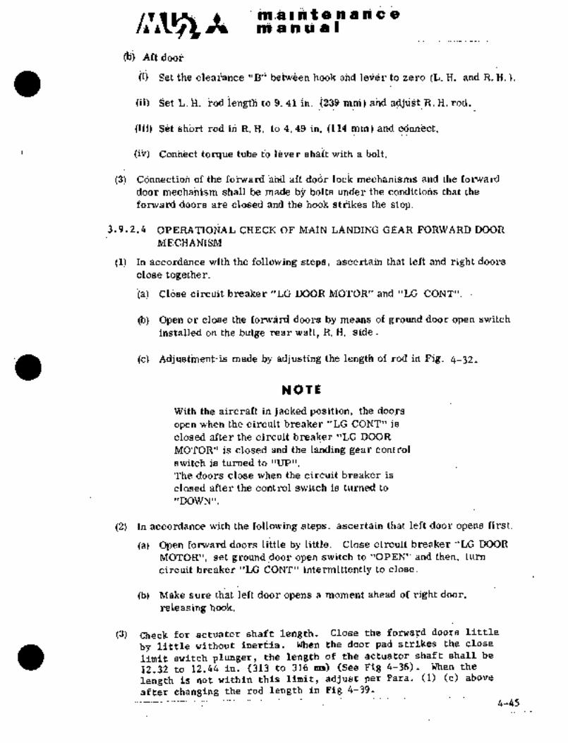
iij iiS1’ beti&e~ h~oic ahii ieii~r.td zero .(L. If; and R. ~-Ii).
(ia ~et j; ~od ie~ to :9; 41 ih::2i39 miii) aild k~ rod;.
ciii) i3b;rt rod id it. I~. tb 4. 49 iB. ili4 ~in) End ddiihi~bt.
i~ii) doiihect torque ti~be tb.ieirer with a kblt.
i3i Cd´•n6ectidh of the ~ha a~ doijr ibck and the fdrvard
door mechanism shall be made b~ bolts under the conditiolis that the
forward doors are closed and the hook strikes the stop.
~.9.2.4 OPERA’rIOrjA~ CkECK OF MA~N LANDING GE#R FORWARD DOOR
ME CHANISM
(1) In acjcdrdance ui~th the following steps, ascertain that left and right doors
close, together.
(a) C1Gse circuit b~aker. "LG DOOR MOTOR" and "LG CONT".
(b) Open or~l6se the fonjv8rddoors bymeans of ground door open switch
instsilledonth’8 bulge re;ar wall, R. H. side.
(c) ~Adjustinent-is ~made by adjusting the length of rod in Fig. 4-32.
N;O T
With the aircraft in jacked position, the doors
open when.the circuit breaker ’´•’LG CONT" is
’closed after thecircuit breaker ’;LC DOOR
MOTOR’; is.closed and the landing gear control
switch is turned to "UP".
The doors close whenthe dircuit breaker is
clos~ed after the control switch is turned to
"DOWN".
(2) .In accordance with the following steps, ascertainthat left door opens first..
(a). Open fo~ward doors little by little. Close circuit breaker "L;G DOOR
MOTOR", Set g~ound door open switch to "OPEN" and then, turn
~ircuit breaker ’’LG ´•CONT’’ intermittently to-close.
(b) Make sure th;7tieft door:opens.a moment ahead of:right door,
releasing hook.
(3) Check for actuat’or ´•sha~t :length. ’Close the.forward doors Little’
by.little withdut inertia,~ When the door pad strikes the´•close
’1‘2.32 to 12144 in; ´•(j13~; to (See Fig 4-36~:. When thelimit: sJitch: plunger the length of the´• actuator shaft shall be
length is not within this limit, adjust per Para. (1) (c) above
after changing´•t~ie rod length inF~ig’4-39.:_~._._.._ ....._.:._.
----~´•1 4-45

maintenanceman ual
TEMPORARY REVISION N0.4-2This Temporary Revision No. 4-2 is applicable to the following Maintenance
Manuals
MODEL NO. REPORT NO. PAGE
MU-2B-35/-36A MR-0218 4-46
MU-2B-60 MR-0336 4-46
insert facing the page indicated above for the applicable Maintenance
Manual
Retain this Temporary Revision until such time as a permanent revision on
this subject is issued.
REASON To change the installation procedure for the rod assembly, and
add a check of the safety pin rod.
CHANGE Change Fig 4-39 and add the paragraph 3.9.3A and Fig 4-40A
as follows.
3.9.3A Check of SAFETY PIN ROD
(1) Apply electrical power to the airplane and open main landing gear forward door using the
ground door open switch.
(2) Pull the circuit breakers "LG CONT" and "LG DOOR MOTOR".
(3) Remove the bolts, nuts and washers from the both ends of the safety pin rdd assembly
in the main landing gear door mechanism and disconnect the safety pin rod assembly.
NOTE
After removing the safety pin rod assembly the doors are free to
move. Prop the doors open for clearance purposes.
(4) Remove the cotter pin from the safety~ pin and remove the safety pin and washer from
the rod assembly. Discard the cotter pin. Check the safety pin and the rods for
anomalies as follows:
(a) The safety pin should be constructed of aluminum.
(b) Upper and lower rods should slide-freely and have no sign of corrosion at their mating
(sliding) surfaces.
(c) Inspect the safety pin for corrosion, wear, or other surface damage.
TEMPORARY REVISION NO. 4-2
Page 1/3
Oct. 31/2002

c~nmaintenanceman ual
TEMPORARY REVISION NC).4-2NOTE
Ensure that the grease applied to the joint area fully covers the
mating surfaces.
(5) Clean and lubricate the mating surfaces of jointed area between upper and lower rods
with MIL-PRF-23827 grease.
(6) Reassemble the safety pin rod assembly, install the safety pin and washer and secure
with new cotter pin per Figure 4-40A.
CAUTION
Positioning the large diameter rod in the lower position (upside
down) may result in corrosion in the joint area of the rods and may
result in the failure of the normal operation of the safety pin. This
could bind and/or damage the landing gear doors and the door
mechanism.
(7) Reconnect the safety pin rod assembly making sure that the large diameter rod (Outer
Rod) is placed in the upper position as shown in Figure 4-40A. j
Rod assembly
Fig. 4-39
.qTEMPORARY REVISION NO. 4-2
Page 2/3
Oct. 31/2002
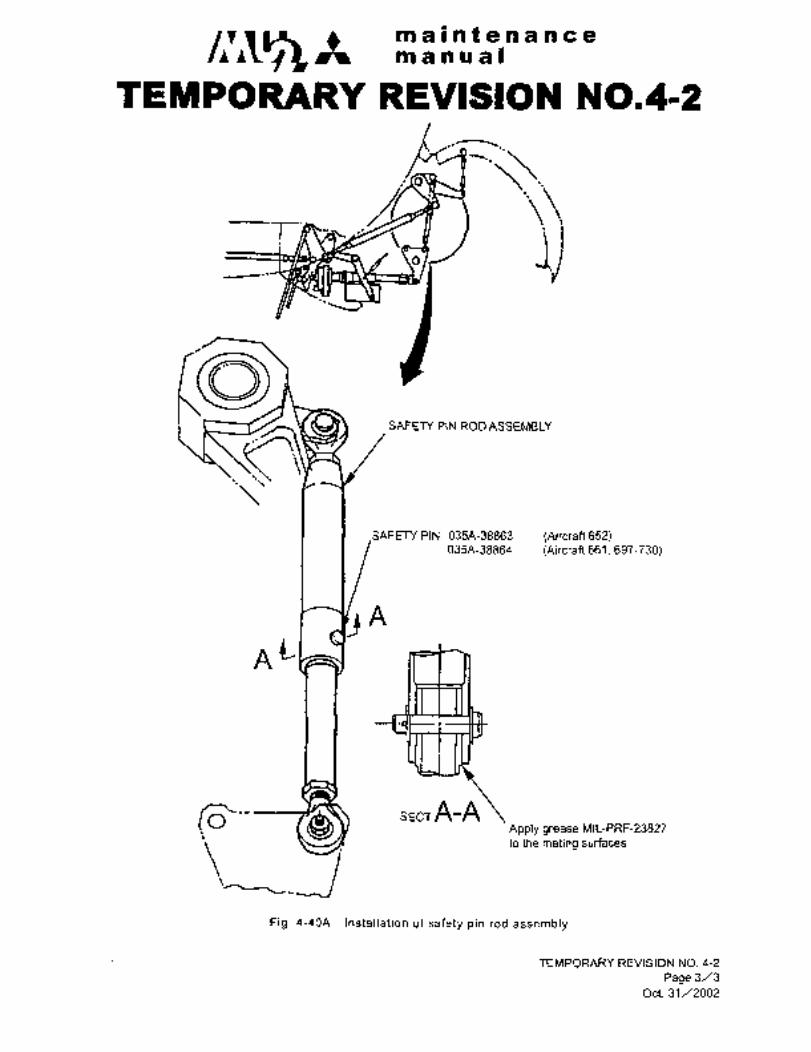
maintenanceman ual
~EMPORLI~RY REVISION ~0,412
ii
SAFETY PIN ROD ASSEMBLY
SAFETY PIN 035A-38863 (Aircraft 652)035A-38864 (Aircraft 661, 697-730)
A
AC
1Sic-- sEcrA-AApply grease Mll-PRF-23827
lodlemaln~rulkra
Pig. 4-4QA Installation of safety pin rod assembly
TEMPORARY REVISION NO. 4-2
Page 3/3
Oct. 31/2002

~le inns is Pii t a a a aa a
.i~ a OP a a
3. 9. 3 MAIN LANDING GEAR FORWARD
DOOR CLUTCH ASSEMBLY
(see Fig 4-40)
The olYLoh assembly is pmvided one set
each Ln L. H. and R. H. The’ cl´•utch
assembly is a coupling having 30
triangle teeth on the side-of link and
transinits torclue by engagements of
teeth; When the emergency gear down
handle.is. pulled, thehook is released
from the pulley, which´• then turns on Rod assem blythe triple thread screw-shaft to escape,anti Iho cl.utch is disengaged by air force
on the doors or pushing force of main
tires.
.In this case, the forward doors ar’e
disconnected from the door mechanism
and in free conditions which can not be
operated by´• electric actuator.
Fig. 4-39
Normal position Emergency gear down position
2 133 2 1
i. Link
2. Link
3. Pulley
4. Shaft
VIEW -A
Fig. 4-40 Clutch assembly NOTE: Please see the
4~;ASReceivedBy
TEMPORARYORIGINAL
REVISIONthat revises this page.
AT P

/I a lk I 7 sa f 46 -n B’i~ C iP
ls7~a gl~ .’P1 OI
3. 9; 4 ADJUSTMENT OF EMERGENCY LANDING GEAR DOOR RELEASE MECHANISM
Emergency landing gear door release mechanism is adjusted by cable tension.
3. 9. 4. 1 ADJUSTMENT OF CABLE TN KEEL
Under.the condition that the smsill lever is set-in eli~ergency gear down
handle and the center le\ier is fixed with a rig pin adjust cable tension
by turning the turnbuckle. The maximum cable tension is 12 lbs.(5.4 kgs).
3. 9. 4. 2 ADJUSTMENT’OF CLUTCH RELEASE CABLE
Adjust the cable with the clutch retaining hook e?gaged.
3. 9. 4. 3 ADJUSTMENT OFHOOK RELEASE CABLE
Adjust cabledettiniihg fitting~o that the ~learance´•between each
hook and outer skin (e) may be 0.20 to 0;32 in. (5 to8 mm) when
the small lever is about to come off the emergency gear extension
handle after the handle is pullep up.
e e, movement of spring
b attachment (Ref.0. llN 0. 19´• in. (2. 8´•v4.8 mm)
Bulge skin
4-47 (48)

´•II
tPI ii i i~ f ij iP C
ii~ ’a ni~ ~aO
c´• G~Z MEi=HAEiISri
GENEiZAL bESCRIPTION (See Fig 4’~41) i’
’I~he landing gear retiracting mec~hahism consists of motor; main reduc-
ti’on torquelimiter, mechanical stop, emergency gear ’extien-
sion methanism, gearbox and torque shafts.
When the ~iheei shaped switch on the switch panel is bper~tBd, the
landing ´•gear retracting ineChanism actiiates electrically together tJith
maih gear forwa~d doors. One motor tiirns Screw jacks of nose and
main gear ai~d retracts or ext~tidsthe landing gears. The motor is
provided with a~ electromagnetic clutch in which 10 centrifugal balls
and brake inechanlsnh are installed in order to improve disengagementcharacteristic end prompt’stop function.
Motorspeeds arereduced to approximately one-sixteenth through the
two-stage spur gears in the main reduction-gearbox. The torque
limiter is provided for the prevention’of overload upon the mechanism
and slips when torque more than 380 to 5~0 in-lbs (449 to560 kg/cm)has been transmitted.
The torque is tramsmitted by ball joint, gearbox and drag strut shpport,9 torque shafts, bearing box, chain and sprocket, nose-gear bevel
gearboxand nose gear actuator. The mechanical stop and emergency gear
down mechanism are provided_between torque shafts.´• The gearbox and
drag strut support have 2 sets of bevel gears and reduction ratio to
jack screw is 35:43.
The reduction ratio of chain assembly is 15:30 and nose gear actuator
15:42.. The bulkhead where the torque shaft goes through is sealed to
prevent air leakage. The mechanical stop opens or closes limit switches
by means:of moving nut~´•and adjusts operational times of landing gear
motor andforward door motor, and furthermore,- stops the retractingmechanism toprevent overtravel in the event of limit switch trouble.
The emergencygear extension´•mechanism is to extend lahding gear
manually in the event of failure! in the motor system. The emergency
gear down handle’ is linked mechanically to the main gear, emergency
unlock mechanism.
The main gear jack screw also serves as drag strut, but’ nose gear
is provided with jack screw,down lock and drag strut.
4.2 NOSE GEAR ACTUATOR
4.2.1 REMOVAL AND INSTALLATION
(1) In advance of removing nose gear actuator, extend~landing gear
slowly with no load~and no inertia, (Band operating shaft at the
back end of gearbox and drag-strut support may be used, see´•Fig 4-41~.
When~the nose gear down lock indicating light (green) illumiaates,
measure the following exposedthread lengths ´•by means ´•of slid$´•calipers~ and record the dimension.
(a) Exposed fhreadlength of main gear ´•jack´• screw (see Fig 4-42).
(b) Exposed thread length of nose gear jack screw (see Fig ‘4-44).
42)´•- P"-mo~ve´•.attaching bolt’of jack screw on rod end~ side per..~ara 2.2.
4-49
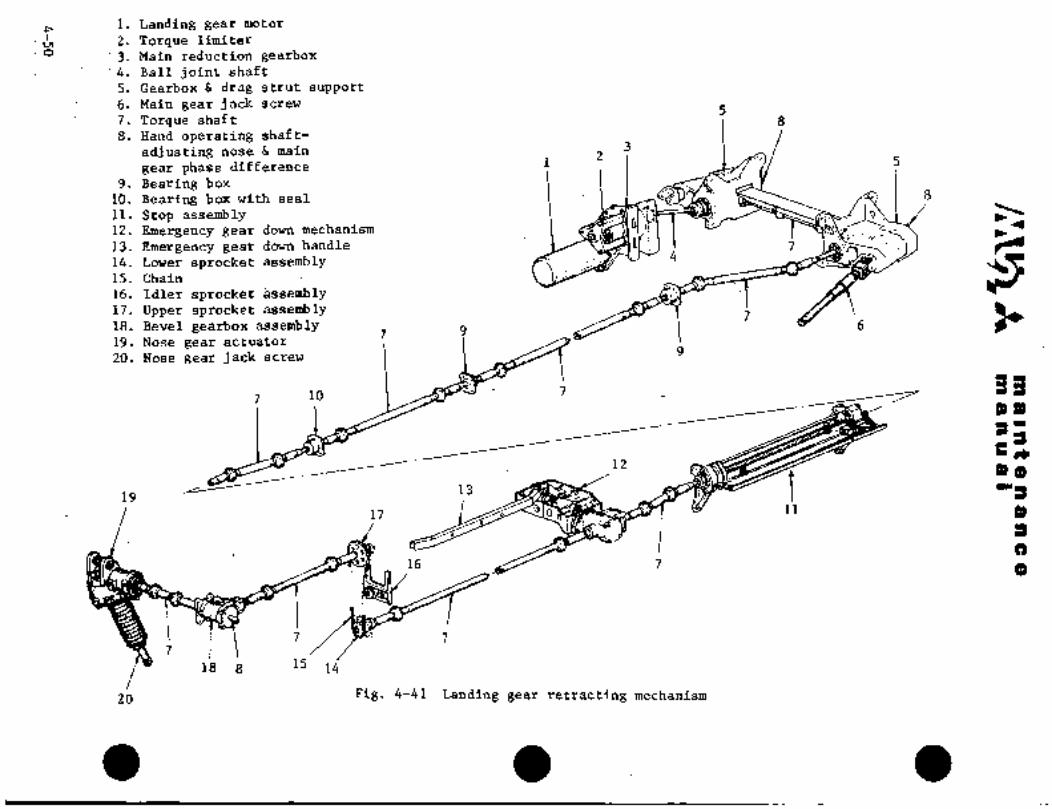
i. Landing gear motor
i ;2. Torque limiterO 3. Main reduction gearbox
~4. Ball joint shaft
5. Gearbox d drag strut support
6. Main gear jack screw5
7. Torque shaft 8
8. Hand operating shaft-
adj.usting nose 6 main2
3
gear phase difference 1 5
9. Bearing box
10. Bearing box with seal 8
11. Stop assembly o
12. Emergency gear down mechanism
13. Emergency gear down handle
14. Lower.sprocket assembly15. Chain
16. Idler sprocket ~ssembly17. Upper sprocket assembly
718. Bevel gearbox assembly
7 9 6
19. Nose gear actuator
20. Nose gear jack screw9
´•7 10 7
OOb
´•13
12
tP)(b
19
17 i 11
C)16 7 (b
7 77´•
18 15
zb Fig. 4-41 Landing gear retracting mechanism

iai leoQ is si is cc 8iEi~iLB ~P
kBTi
When nose gear actuatoror torque shaft is
instaled, reinstall on the same conditions
Oength and locatiori) as formerinstallatibn.
After reinstallation, check for the specifiedvalue by stop mechanism.
(~lj Reinstall in revei´•se sequence of removal.
Exposed thread length
Fig. 4-42 Main gear’ jack screw
SpacerBracket
Bolt 1 r ’I I Stop bolt
Nut I I Nut
L~ockwire I Washer
Nose gear r W~a I Cotter pinactuator
Fig. 4-43 Nose gearac~tustor
ORIGINAL
As Received ByAT P 4-5 Z

It’l~ maintenancem a a a a I
4. 2. 2 ADJUSTMENT AFTER REINSTALLATION OF NOSE GEAR ACTUATOR
(1) Install nose gear actuator after setting the exposed thread lengths of nose
and main gear jack screws to the lengths recorded in accordance with
Para. 4. 2. 1(1), (a) and (b).
(2) After installation, extend gear with no load and no inertia and check nose
and main gear jack‘ screws for exposed thread lengths.
(3) Perform geai´• retraction and extension. Make sure that "DOWN" side and
"UP" side clearances of mechanical stop (clearance between moving nut and
edge of thrust bearing) are the specified values, and that relative position of
nose and main gear is correct, in accordance with Para. 4.7 "ADJUSTMENT
OF STOP MECHANISM".
4. 2. 3 CHECK OF NOSE GEAR ACTUATOR
(1) Remove the dust cover and check jack screw for deformation, damage and
foreign materials.
(2) Check for axial play over the entire stroke. if the play due to thread wear
exceeds ~’0. 014 in. (0. 36 mm), replace screw jack.
(3) Remove rod and clean screw. Check screw surface for lubricant film
(Molykote). Replace screw jack if the lubricant film is peeled off theApplyMolykote greasebottom of screw thread over the entire length.MIL-G-21164 when the lubricant film is not peeled off.
4. 3 DUST COVER
4. 3. 1 REMOVAL AND INSTALLATION (See Pig 4-44)
(1) Remove jack screw attaching bolt (rod end side) in accordance with Para.
2. 2.
(2) Remove clamps and dust cover.
(3) Reinstall in reverse sequence of removal.
NOTL
Check jack screw and dust cover for cleanliness
and no foreign materials such as metalchips, etc.
4-52

I/:~/i sh a a a a I
i 2 ~3 2
i. Rod endExposed thread length
2. Clamp
3. Dust cover
2 12 3
Fig.4L44 Dust cover
4. 4 MOTOR AND TORQUE LIMITER
’4; 4; 1 REMOVAL A´•ND INSTALLATION (See Fig 4-45)
(1) Remove motor cover.
(2) Drain oil through 2 drain ports on the re~uction gear box.
(3) Remove motor attaching bolts. (4 ea.) and remove motor.
(4) Remove torque~ limiter´• case attaching bolt’s (3ea.), tab washer ´•and
nut on the top of the torque limiter shaft and remove torque limiter
from shaft.
NOTE
Check the friction surface´•of
the torque limiter forcl-ean-
liness, especiailji for’any’oilpenetration which may exist’.
(5) Reinstall in reverse sequen~e of removal.
(6) Fill-with Grade L until oil over’flows the upper port.
4. 5 BALL JOINT ASSEMBLY AND TORQUE SHAFT ASSEMBLY
4. 5. 1 REMOVAL AND INSTALLATION (Fig 4-41)
(1) Extend landing gear and set the forward doors in open position.
4-53
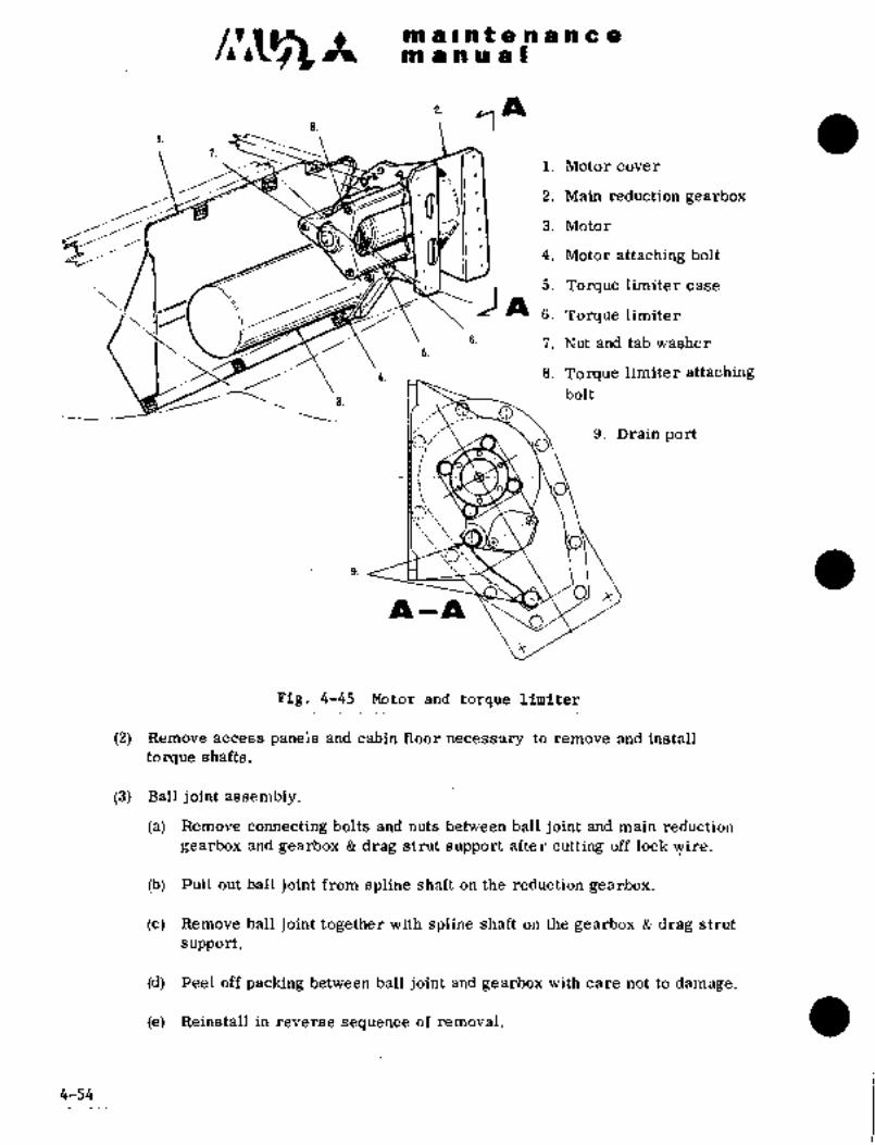
maIIlltaaaacam a a II a a
2. IILs. Y
i. Motor cover
2. Main reduction gearbox
3. Motor
4. Motor attaching bolt
5. Torque limiter case
3
6. Torque limiter
a. 7. Nut and tab washer
4. 8. Torque limiter attaching
bolt
0‘
9. Drainport
~P 1 ~LI1
Fig. 4-45 Kotor and torque limiter
(2) Remove access panels and cabin floor necessary to remove and install
torque shafts.
(3) Ball joint assembly,
(a) RRmove connecting bolts and nuts betw~en ball joint and main reduction
gearbox and gearbox drag strut support after cutting off lock wire.
(b) Pull out ball joint -from spline shaft on the i~eduction gearbox.
(c) Remove ball joint-together with spline shaft on the gearbox drag strut
support.
(d) Peel off packing between ball joint and gearbox with care not to damage.
(e) Reinstall in reverse sequence of removal.
4-54

ni a-i a ri C a
~tP In~iu a I
(.4) ’sh;2ft a~sembly
~e afop bolts, pins, ~nd Irasherd in Fig 4-411
Slide the’ shafts, tii~zd remove ~he’ other ends from the
spline.(C) Sii‘de the sh’afts to~ft;e reverse direction andr~emdire.
(d) The torque shaft aSsembly of main gear ~orward doer raechanisai
in Fig ;6-41 dan n~t be slid, so remove connecting bolts, then pull
buf the shaft.
(’e) As the rubber bb‘ots of unive’rsal joints are ebsily broken, remove
with care.
(f) ~Reinstall in reverse sequence of removal.
NOT IE
Mal~e sure that.~top bolt,nutj: washer and~otter pinare properly installed.
(5) Inspection
(s) Wipe off grease and che’ck~spline for cracks.
(b) Pull out connecting bolts and check’bolt holes for looseness, When
the looseness exceeds 0.008 in. (0.2 IIIln),), replace with oversize
bolt or new shaft assembly.(c) Check universal jount for excessiveplay. If the play’exceeds 1.50
replace with new shaft assembly.
(6) Apply grease MIL-G-23827 on splines when installing.
(7) After installation, perform operational test in accordance with Para. 5.1
and adjust relative positions to.nose gear, mechanical stop and main gear.
4.5.2 CHECK OF.TORQUE SHAFT SYSTEM
To check for play over the entire sys’tem, turn by hand the hand operating shaft
on the rear end ofthe RH gearbox and drag strut support or RH barrel slowlyand measure revoltltion angle of the shafter barrel until nose gear -jack screw
barrel:begins to-turn. When the angle exceeds 490, check per Para 4.5.1.
4.6 CHAIN ASSEMBLY (See Fig’ 4-46).
Keep chain cleanand free of dirt, rust and corrosion;´•for ins~ection and´•
wear limitations see Chapter II,~qara. 11. Adjust chain tension by moving-the idler sprocket shaft ~to the left or. right. Allow approximately
´•’0,.188 to 0.313 in.(5 to-8´•mm):sllack as,measured with th~ thumb and the
borefingei: compressing the,middle o~f the chain~span.´•: The proper amount
~bf slack is 2%´•to’3X of the span.
4-55

nldh~a I) As Received Bym 1 II nt iei h ti in e a ORIGINAL
AT P4. 6. 1 RENioVAL AND INSTALLATION
jl) Relinove access panel.
(2) Move idler sprocket and loosenchain.
(3) Remove chain clip and remove chainfrom upper and lower sprockets.
14) liLclnelall in reverse sequence ofChain
Idler
NO TE
When new chain is installed, check
chain tension after operation and Lower
adjust chain tension again if
necessary.
Fig. 4-46 Chain assembly
4. 7 ADJUSTMENT OF MECHANICAL STOP ~See Fig 4-47)
4. 7. 1 CONNECTION OF TORQUE SHAFT
(1) Connect main gear, nose gear and mechanical stop under the followingconditions.
(a) Main gear Exposed thread length of jack screw (drag strut)17. 62 in 0. 04 in. (448f 1 mm)
(b) Nose gear Center of the nose wheel is at the position 18. 07 -f 0. 12 in.
(459 f 3 mm) from the ceiling of nose wheel,
(c) Mechanical stop Clearance B O
To connect torque shafts between mechanical stop and main gear, the torqueshaft just before L. H. gearbox Q drag strut support is convenient for
adj ustment.
To connect torque shafts between mechanical stop and nose gear, the torqueshaft between bevel gearbox and chain may be used.
To operate main gear or nose gear separately, disconnect torque shafts as
mentioned above and turn the hand operating shafts on the rear end of gear-
box drag strut support for main gear and on the left end of bevel gearboxfor nose gear.
(2) Extend landing gear and set under the following conditions.
(a) Main gear Exposed thread length of jack screw 0. 69 in f 0, 04 in.(17, 5f´•1 mm)
(b) Nose gear R.H. More than 0. 08 in. (2´•mm) clearance to reach
downlock groove end.
L.H. More’clearance than R.H.side
4-´•56

ra 8 1 tllf 8 Pld a a 8
ao a a a a i
iF--c2ci
/L!
4 32 003
MAIN SHAFT~
:2. GUIDE ’SHAFT
3. TRAVELING NUT ASSEMBLY.
4. STOP NUT
Fig, 4-47 Mechanical stop (1/2)
4;(57)58

f’8 66 8 611 cC 9)
p~id. 61 66 681 s
Ad3ii~t ‘Sidi~ aodljle nlits spacer oi~ ~tbp;sd t~e"A’’ niajr I~ zejro, (decision of maxili~uni stroke)
;6 B (S~N 652~8 only)
nl’ ´•On’-li o´•i´•.j
I´• ´•1
3 2
i. Moving’nut rMo~e than 0. 0´•2 in. (1 mm)
8. lip zone switch (S28S) at the point whei´•e limit
3. UI~ limit; switch (S28i) i switch 8283 actuates, Mofe
4. Spacer Lr than 0. 12 in. (3
(lockinX) 1 mm) where S282
6 ndjusting nut I j 1 actuates.
Fig. 4-47 Mechanical Btop (2/2)
Si7.2 ADJUSTMENT dF MECHANICAL ‘S~O‘P LIMIT~.SWITCH
Applicableto aircraft.S/N 652SA
Refract landing gear slowlyand continuously under no load and no inertia
condition to ´•UP position. Check for the following clearances:
(a) Adjust the "UP LIMIT" switch (S282) toactuate whenclearance "B"
is 0.16 to 0.20 In. (4.0 to5.0 mm).(b)~ Adjust the "UP ZONE" switch (8283) to actuate when clearance "B"
is 0.14 to 0.16in. (3.5 to 4.0 mm).
Applicable to aircraft S/N 661SA, 697SA and subsequent
Retract landing gear´•slowly and continuously under no load and no inertia
condition to UP position. Check-forthe following clearances and adjustas required.
(a) Continue retraction slowly until mechanical stop reaches the endof
its travel (zeroclearance). Measure and record for clearance of "C1"
(b) Extend the landing gear by hand past the point where the "UP LIMIT"
switch is in the OFF position.(c) Retract the landing~ gear by hand until the "UP LIMIT" switch is in
the ON positidn, ´•measure and, record:clearance "C2"
(d) Adjust fhe~"UP LZMIT" siwtch so that C2- C1 =0.16 to 0.20 in.
(~4.0 to 5’.0 mm).(e) Continue.o retract the landing gear by´• hand until the "BP ZONE"
switch is~ in the: ON position, measure and record´•clearance ."C3)’(f) Adjust. fhe’."UP ZONE" Switch 80 that C3 C1 0.14 to 0.16 in.
(3.5 To 4.0 mm).
4.7.3 OPERATIONAL. TEST:OF MECHANICAL STOP (See´•.Table 4-1)
Perform landing gearretraction and extension, and.make sure of the’´•specifiedvalues in Table 4-1. :For operation ~ith´• no load and inertia, check alterten: cycles.
4-59

maintenancemanual
TEMPORARY REVISION N0.4-3This Temporary Revision No. 4-3 is applicable to the following Maintenance
Manuals
MODEL NO. REPORT NO. PAGE
MU-2B-35/-36A MR-0218 ´•4-6~
MU-2B-60 MR-0336 4-46
Insert facing the page indicated above for the applicable Maintenance
Manual
Retain this Temporary Revision until such time as a permanent revision on
this subject is issued.
REASON To add a torque check of MLG thrust gearbox attachment bolt.
ADD Paragraph 4.8 and Fig 4-47A as follows.
4.8 TORQUE CHECK OF MLG THRUST GEARBOX ATTACHMENT BOLT
Inspect to ensure the torque is correct for all four (4) MLG Thrust Gearbox attachment bolts
per the Figure 4-47A to preclude a loose bolt condition; If a bolt(s) is loose, replace the
nut(s) and retorque to proper value as required.
TEMPORARY REVISION NO. 4-3
Page 1/2
Oct. 31/2002
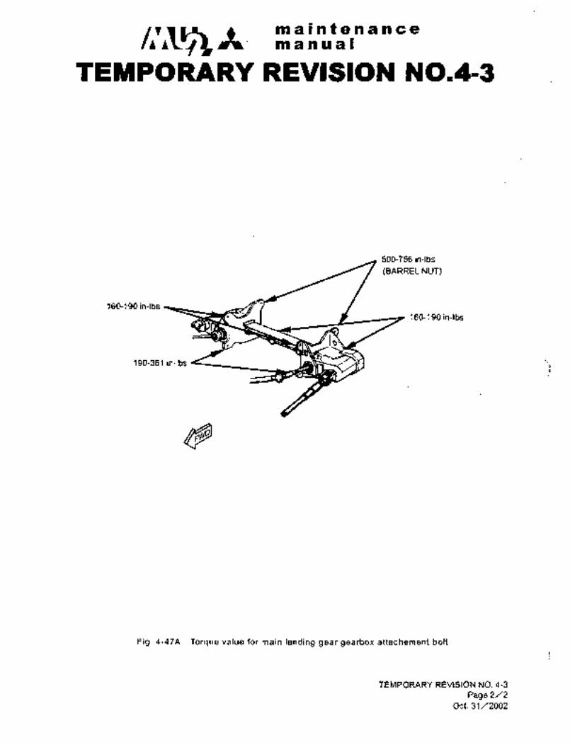
c~S,maintenancemanwal
TEMPORARY REVISION N0.4-3
500-756in-lbs
(BARREL NUT)
160-190in-lbs
160-190in-lbs
190-351 in-lbs
Fig. 4-47A Torque value for main landing gear gearbox attachement bolt
TEMPORARY REVISION NO. 4-3
Page 2/2
Oct. 31/2002

qs ´•’PP ~i W i~ QIlh a a a a(
bB r
ana ~heckint5 andijl~oHniiicai stdi,
switch adjristing. point
Ejrpbs~eil thread length of inain
Connection of torque gear jack screw 17. 64 f 0. 04 inO Mm)shaft
Center of: nose wheel
WP-18. 07~1t0. 12 in(459IT3mm)
trp zone switchQ14-´•al 61n
Sutitch attaching: screw(3. 5--4mm
~lljp limit ~witch61 6-Q20in;
Switch attaching screw(~4-v 5 mm)
Maingear up indicating ss than
2in(8mm)lSee Pars. 10~a switch
´•a,~o Nose gear up indicating IL24--1.2in.lSee Pars. 10
~7 olswitch 6^´•3 Omm)
a02~008in’l A ct"ating point of~ up:limitNo load :I 1(O; 5- 2mrn )I switch.
with inertia No shbck Disconnecting characteristici.
of motor.
Exposed thread length of mair\
0 I Igear jack screw 0. 67 fO. 04 in. ii(17fl mm)
ore than O. 08 in. (2 mm)clearance to reach nose
gear downlock groove
I I lend (R. H.
I JMore clearance than R. ii. (L. ii
41 1 Ispacer th’ickness, Adjusting nut
C11Down limit switch ’16’ 0.045" See Para. 10
4 t~ mm,
002Ya08iri. point of down limitNo load O. 5--2mm switch.with inertia No shock
Disconnecting characteristic
of motor’
NOTE: Please see the JTable Y-l Specified values for mechanical stop
4-60 TEIWPORARY
REVISION
that revises this page.

c~slt´•ni ail nt en a a a a
m a a a al
5. OPERATION AND CHECK FOd LANDIrjG ~EAR SYSTEM
5.1 OPERATIONAL TEST
dperatior~al test (operational coi~dition with no load and, with inertia) is peliformedas in the following procedures. If major components of landing gear
Bystem ar~ replaced or adjustment is made bjr ai8connecting power train of landinggear i~etracting mechanism, operational test Should be performed as follows:
NOTE
(i) When l~ding gear is performed~three times
of up and abwn operations continuously, it’is
recommended to stop operation for about 20
minutes to cool:gear motor and door motor.
(ii) When high current runs or any abnormal
condition is observed during gear operation,
stop operation immediately and incluire into
the cause.
(iii) When airplane installed battery is used for
gear operation, care should~be taken not to
drain battery capacity complet~ely.
(1) Jack airplane.
(2) Close the following circuit breakers and turnbattery key switch to ON.
"LG MOTOR""I~G CONT’!
"DOOR MOTOR""LG POS IND"
~3) Ensure that nose and main gear downlock indicating, lights (green) are
illuminated and the unsafe light:is OFF.
(4) Place gear control switch to "UP" positionand retract gears.
(5) Ensure that unsafe light (red)illuminates, and that as soon as it goes off, nose
and main gear down ´•Iock indicating lights go off.
(6) Ensure that nose gear up limit-switch actuatesi gear retraction c~ases and
main gear aft doors are completely closed.
(7) With gears retracted, open main gear foiward door and check for the followingitems.
(a) A~minimum clearancef ~.´•79 in’.~20 mm.) between left and right, main gear
leg~ end and main gear well’ wall. --A’ minimum clearance~of;0. 2 in: (5 mm)between the other points of thc~leg and main gear well wall.
4-61

m a int a ti a n a ani a Iri i~ a i
(b) o. o~ In. (O. 5´•ci inm betw~bn mnih gear aaci leg att~ch-
ing fittihg stop.
(C~ _cl~arancle between rir8s and doors, and
-tire and ~main gear for~ard door, and ~nore than 0. 2 in: (5~ mmj of clearancebe’tween’tiC and forward door cutout.
(d) More than 0. 79 in. (20 mm) of clearance between nose tires and ceilingof nose gear wheel well.
(e) Exposed´• thread Length of main gear drag strut jack screw is about 17.64
~11,1)´•1I, IAAY+I
(f) Up side clearance of mechanical stop is 0. 02U0. 08 in. (0. 5´•´•´• 2 mm)
(No shock against.stop).
(g) Up limit switch, up zone switch and up zone safety switch should be at
position operated by moving nut.
(h) Nose~and main gear position indicating lights (green) should be off.
Unsafe light (red) should be off when main gear aft doors are closed.
fifth stroke of retraction and continue retraction manually. Check mechanical(8) Extend landing gear once and retract again. Stop retraction at approx. one
stop for clearance at th~ point where each limit switch actuates.
Switch Clearance
Nose gear up indicating mechanism 0. 24 ´•e 0. 32~ in. (6. 0-8. O mm)
Up zone switch’ 0. 14--´•0. 16 in. (3.5-´•4.0 mm)
Up limit switch O. 16´•Y 0. 20 in. (4.0´•v 5. O mm)
(9) Place gear control switch in DOWN position to extend gears.’ (If main gear
aft door is open for inspection, close door before extending gears.
´•(10) Ensure that unsafe light (red) illum~nates and goes off, and thatgeardown lock indicating light (green) illuminates.
(11) With gears in "DOWN" position, check for the following.
(a) Interference in nose and maingear wells.
(b) Exposed thread ~length of main gear drag strut jack scrow should be
0.69.+0.08 +2_,.,,
in. (17.4 _Imm).
(c) Clearance at DOWN side of mechanical stop should beO to 0.04 in.
(O to l~mm). (No shock against stop)
4-62.

iPi’ta i iiit 22 jEh ii c e
~i ii ii ~C a i
(d N69~ ge~r dowiilocic (k.H. ii cii´•arcince more tti~ui ii. OS in. (2 mm) to
lock groote ahd L. ii. cio\kinlock has more clearance than R. H.
..sii~e..
(e) Pli~ngBr of nose gear down limit switch does not rea~h the end of its travel
and attaching bracket is not distorted.
(ij .Nose and nha~n gedr fidsitionindicatjlng lights (green) are illuminated.
(12)’ Retract landinggearoni~e and agaiir. .Stop extension at
approjrinately one fifth stfbke di extCnsidn´•and coiitinue exten-
sion manually; Check mC3ctianicai stop for clearance at the pointwhere each limit switch actuates.
Switch Clearance
Down ii--it switch 0. 12 ´•v 0. 24 in. (3. 0- 6. O mm)
(13) Time from start of movement of gear to end of movement both for retraction
and extension shall be within 11 seconds.
(14) ~anding gear position indicating light indicates correctly.
While gear retractingGear down position oi´• extending (Door Gear up position
opening or closing)
Unsafe light(red) OFF Unsafe light(r´•ed) ON Unsafe light(Red) OFF
Nose.light(grsen) ON Nose light(green) OFF
L. H. light(green) ON L. H. light(green)´•OFF
9. H. li_ght(green) ON R. H. light(green) OFF
5.2 OPERATION AND CHECK OF MAINGEAR FORWARD DOOR
In regirdto operation Bnclcheck of main pearforward:door, gee P$ra. 3. Y: 2. 3.
5. 3 OPERATION AND CHECK OF NOSE GEAR DOOR
(1) Clearance’, between.ndse gear door and tires is more than 1. 18 in. (36 mm)
in door opening condition and 0, 74 in. (20 mm) in Idoor~ closing condition.
(2) When the moving nut of mechanical stop reaches the end of its stroke (gear up)’and a weight of 20 lbs!9 kg) is hung~on the door center edge, ~the door
should come off mold line gbout 0. 40- 0. 59 in: (10´•v15 mm).
4-63

aT re II ~i t a h ai n-’ce a
ne a a a at
5. 4 ’MEASUREMENT OF cvnnEN~jr ~oR 1LIAIN GEAR DOOR MO’i‘OR
Electric curi~ent of main gear door motor should be less than 14A during door
ope 1´•a t.~i ol~
When major compohents of main gear dooi´• mechanism are replaced, ~easure
electric current as necessary.
5.4. 1 PROCEDURE
(1) Disconnect wire G146R12 cohnected to door motor relay on the rear bulkhead
of n. H. main gear wheel well, and connect it to the terminal of ammeter
(30A max. Connect a wire (MIL-W-508G Ty~e II,’AN-12) to terminal
of ammeter and connect the other end of the wire to the terminal of relay.
(See Fig 4-48)
MIL-W-5086 Type II AN-12
r------7
To door motor1
A mme ter
i-------J
nelay
Fig. 4-48 Measurement of door motor current
CAUTION
’rurn all power s\~itches to "OFF" before connei3tingwire. Wire connecting to ammeter should not contact
with main gear forward door.
(2) Operate main gear forward door and measure electric current of motor and
record. It should be 7 h´• 9A (No load). This does not include current value
at the moment of starting.
(3) After measurement, remove ammeter and wire and connect wire to its
original position.
4-64
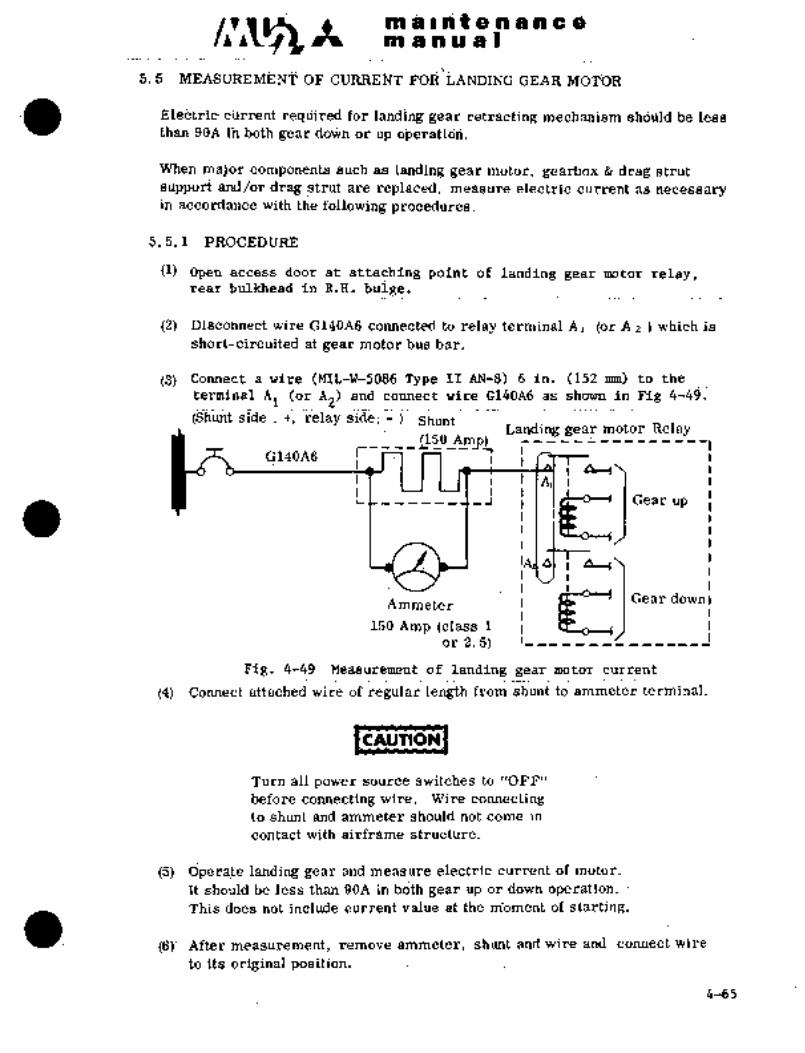
´•’I
ai ii a iii~ a ;d ac~ isll ii iia I...__._..._.. _.._. _...
5; OF i=UiiiirjMT FOfi LANDING GEAR MOTOR
ti~ari 98A iii do~a br up oiokratid~.essE~lei3trii=´• ciirreht i´•~qiiired Br iaiiding gedr retlahting mechanism shouia 6e 1
When maljor coinponents suc~i as lan~ing gear~motor, gearbx drag strut
support alid/or drag strut a~rti replaced, measure electric curk.ent as necessaryin acCojrdance with the following procedures.
5, 5. 1 PROCEDURE
(1)’ Open access door at attaching point of landing gear motor relay,rear bulkhead in R.H, bulge.
(2) pisconnect wire G140A6 connected to relayterminal Al ´•(or A z which is
sh6rt-circuited at ~ear motor bus bar.
(3) Connect a wire (M;lL-W-5086 Type ii AN-8) 6 in. (152’nmi) to the
terminai Al (or A2) ana~ connect wire d140A6 as shown in Fig 4r49,
side j~ ShuntLanding gear motor Relay
~15_0Amp) r-----’--------1G140A6
IAlt
r
Gear up f*L-----,l,~
150 Amp (class1I\j Gear down IA’mmeter
or 2. 5) 1-
Fig. 4-49 Measurementof landing gear motor current
(4) Connect attached wire of regular length from shunt~ to ammeter terminal.
CAUTIOPI
Turn all power source switches to "OFF"
before cdnnecting wire. Wire connectingto shunt and ammeter should notcome in
contact’ with air’frame structure.
(5) ’.Operate landinlg gear and measure electric current of motor.
It should be l´•ess than 90A in.both gear´• up or down operation.
This does not include iturrent value at the moment of starting.
(6)’ After measurement, remove ammeter, shunt and wire and connect wire
to its original p~sitioli.
4-65

~tl a i a t a A a ii~ a 8in a an a I
i:i ~P
t´•t!:’ 1
’1’-’
6. EMERGENCY GEAR EXTENSION MECHANISM
The emergency gear extension system extends
the landing gear manu~llv in the event of trouble
in the electrical system. ’I’his mechanism,
however, can not be used for retraction.
To ol,erate, pull up the handle on the floor of
the pilot’s compartment, a small lever in the
handle will I.hen actuate lo disengage main
gear and aft door locks and clutrth
of the mnin gear fonvanl door mechanism. Pig. 4-50 Emergency gear down
Doors are now free.handle (A) and gears (B)
Pump the lever
approximately 215 times ("1) or
approximately 130 times (*2), and
the gear ~ill extend until it reaches
down-lock position. The~ completion of gear extension is indicated by green
lamps illuminating and handle pumping becoming heavy.
*1 Aircraft S/N 652SA and 661SA
*2 Aircraft S/N 697SA and subsequent
ORIGINAL
As Received ByAT P
4-bb

at~8 LP’ I~ao f 8 a a a a a
as a a a a I
CAQITION
To make emergency gear extension, pull out circuit breakers
LG CONT, LG MOTOR and DOOR MOTOR and place landing gearcontrol switch to DOWN. Do not perform this operation with
the above circuitbreakers in CLOSE positions.
Small
lever Handle Handle
(Aircraft SjN 652SA and 661SA)I~ockwire o. ozoia
Handle~-W-821 COMPI TEMPl/aB
Small leverHandle
Clutch
(Aircraft-S/N 697SA and subsequent)A Emergency gear down handle B Gear mechanism
A Emergency gear down B´• Gear mechanismhandle
6. 1 ADJUSTMENT AND OPEII~TIONAI, TEST
(1) Jack up the airplane.
~2) Retract landing gear.
(3) Pull emergency handle to the extent of small lever comin off.
(a) Hook of’ main gear forward door is pulled gnd doors are unlocked.
(b) Clutches of main gear fonvartl door mechanism are disengag~ed and the
doors become.fr’ee.
4-67

malnteilancenn a or a a
(C) Hook of main gear aft door is pulled and doors are unlocked.
Rcnlove access doer (F. E’rA.:~035rV 4285) between keels nnd check the
following items.
<:law on the center lever engages ~vith ratchet teeth. (Fig 4-51).
(h) No abnormal condition in cable system and center lever mechanism.
(5) L. H. and R. H. clutches which release n~ain geai´• forward doors, do not reach
the ends of theii´• travels.
(6) Clearances between hooks and rollers in forward and aft doors should be more
than 0. 08 in.(2 mm).
Pe-~form emergency gear extension operation and check the following items.
(3j Ascertain that the operation is performed smoothly.
(b) Landing gear position indicating lights (green) which indicate main and
nbse gear being in down position illuminate.
(8) Adjustments of Para. (5i and (6) above are made by means of cable detaining
fitting. Nut
Inner cable
Outer cableBracket
Cable detainingfitting
6.2 RESET AND CHECK A FTER EMERGENCY GEAR EXTENSION
After emergency gear extension, reset and adjustment can be done on the groundwithout jacking as follows:
4-68

q ii.n Q ;8 a a P;i E
a’i~ ~i w iiiij a I
~1) cable assembly;
(a) Slf sinali handle into the emergency haadie and- iretGm ttie handle to
the lidrmaf Intall (bQ-~;32i .Ci2~Dia) (S/Ij 697SA
a;i~d´•(b) access doqr (F. S1;A4025ru4285) between keels ai~d return the
ceht~i. lever; ulj to th~ positioi~ where claw diseng8ges (See Fig 4-51);
(c) Pull back hbok release.cable;
-Rest of i~lutch ~asSembly;
(a) actuator of main gear forward door rriechanism to the position
.where the forward door open limit switch actuates, by using the ground
door open switch installed on the aft bulkhead of R. ii. bulge main gear well.
(b) Align clutch mating mal-k and engage each link.
(c) Push uyj hook to stop, and return pulley while winding back-clutch cable
(See Fig. 4-52).
(d) Set hook in pulley groove.
B./r .1
1. Bracket
2. Centerlever’
3. Ratchet teeth
4. Claw Y /4
5. Spring8
G. Cable (to haridle in cockpit) 3/ ..i.7. Clutch release cable
8. Unlock cable´•
´•Fig.: 4-51 ncset after -emergency gear extension
(3) Operate forwflrd door mcch;lnis.m and make sure thai Opening and cl~,sj!lg
oper´•ations’zire i,erlome~l liormally.: The:fonvard.door c~in bu opened or
closed I,?; usi;iF; Xi.ountl door open switch on th, bulgc:.l´•ear bUlkhC?L7tl of Ii; I-I.
mai:n gear whc´•cl \\,ell.
4-69
an a In t a a a a c a
al a a a a I
(4) Operation of forward door shall be as follows.
(a) Close the circuitbreaki3rs DOOR MOTOR and LG CONT.
(b) Place landing gear control switch to "DOWN."
(c) Turn the forward dooroperating switch in R. H. main landing gear
well up or down. The door fully opens or closes.
(d) After operation, close the door fully by the forward door operatingswitch turned down and return the switch guard and apply safety wire.
(5) Pull out all circuit breakers.
NOTE
When the forward door is checked for operation,pull out circuit breaker "LG MOTOR" to avert danger.
IcnuTlu~CAUTION
To change the sleeve tend of outer cable) location of
Teflon cable (lock release cable) will cause a changein sag and travel. Sufficient care should be taken
when changing the sleeve location.
Lockwire in Para. (1) should be cut in first hand.le
operation of emergency gear down. Specifiedlockwire must be used and one lockwire must
pass through holes on the both ends.
4- 70.
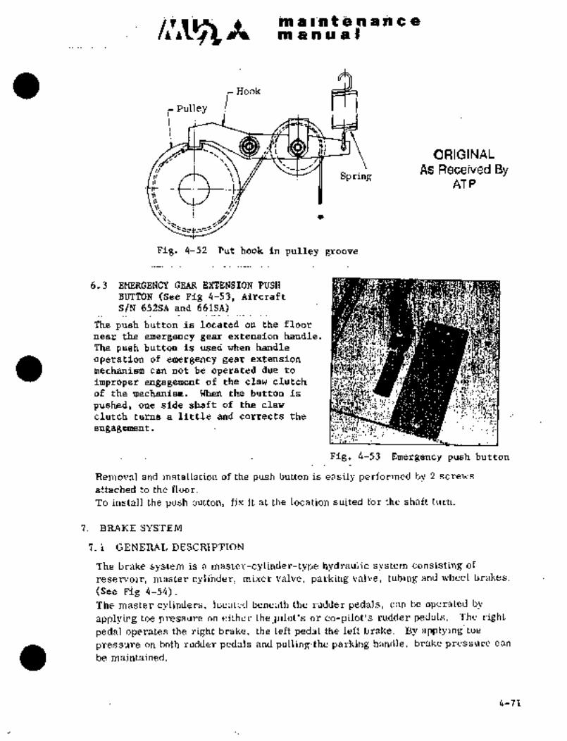
a´•
iii~ 01 4_44 t ;iec $B a a a a
~iti a~ la~ a a
Hiioi<
Pulley
ORIGINALI j
As Received BySpring
AT P
Pig. 4-52 Put hook in pulley groove
6.3 EMERGENCY GEAR EXTENSION PUSH
BUTTON ´•(See Pig 4-~3, Aircraft
S/N 652SA and 661SA)
The push button is located on´•tbe floor
near the emergency gear~extension handle.
The push button is used when handle
operation of emergencygear extension
mechanism can not be operated due to
improper engagement of the claw clutch
of the mechanism. When the button is
pushed, one side shaft of the claw.
clutch turns a littleand corrects the
engagement
Fig._4-53 Emergency push button
Removaland installation of the push button is easily performed by 2 screws
attached to the floor.
To install the push button, fix it at the location suited for the shaft turn.
7. BRAKE SYSTEM
7.. 1 GENE~RAL DESCRIPTION
The is _a master-cylinde’r-type hydraulic system consisting´•of
reservoir, ´•master cylihder, niixer valve, parking valve’, tubing and wheel brakes.
(see Fig 4-54).
The master cylinders- locflted benejth.the rudder: pedals, can be ~perated by
~plying toe pressure on either the Ipilot’s or co-pilot’s rudder pedals. The! right
pedal operates the right brake; the le~ftpedal ~the left brake. By applying:toepressure on both rudder‘pedals and pulling4he parking handle, brake pressure can
be .maintained.
4-71
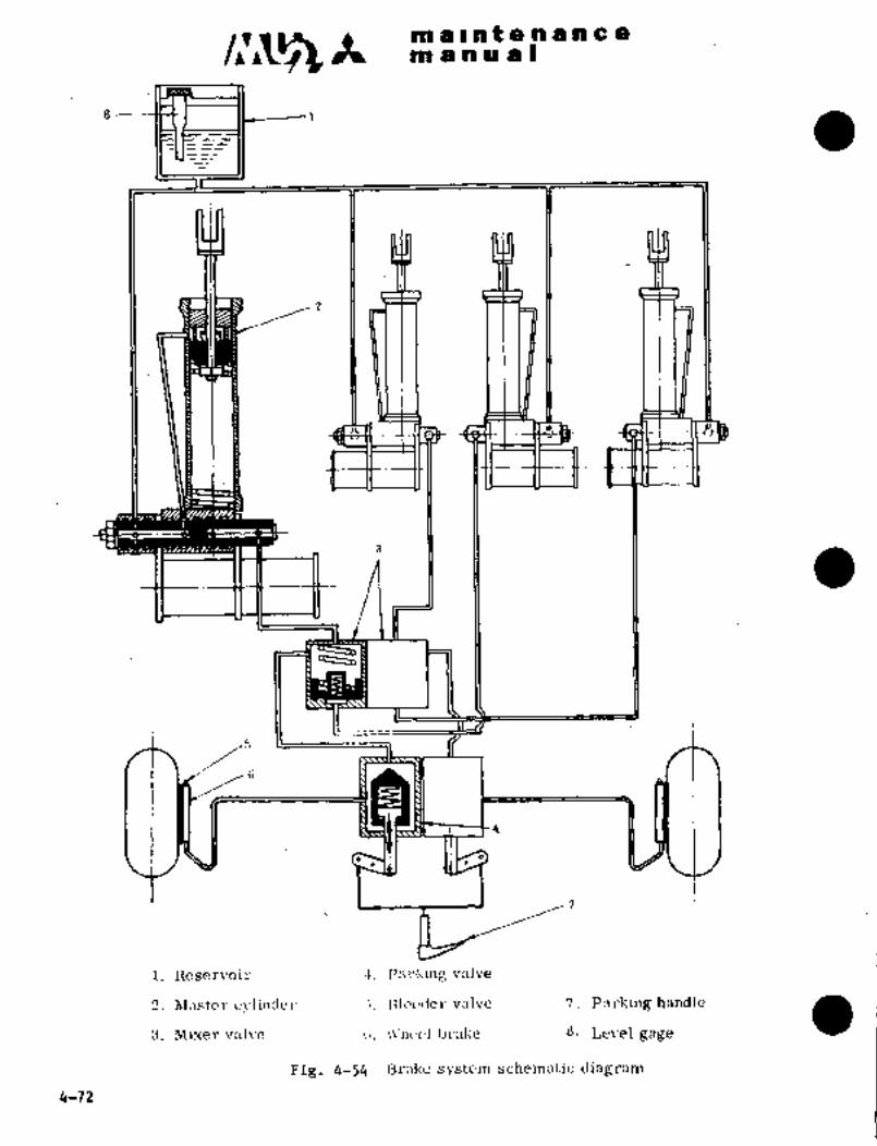
c~s It 191 a Ilhtenancenl a a a a I
s -----~t3 I II I
i. ncservoir 4. PfrltinE; valve
2_ M;lstcr c\ilindcl´• ;5. nlec´•´•der valve 7. Parking handle
3. Mi?terv~l\´•e i;. bral~e ~8´• Levelgag’e
Fig. 4-54 Brnke system schematic diagram
4-72

In at at a a a to a a
m a a a a I
7.2 .RESERVOIR (See Fig. 4-f5)
Tj~he reservoir, located on L. H. side of the r~ear wall of the electronics compart-
ment’, supplies hyd~aulic fluid’ (MIL-H-5606) to the master cylinders. There is a
level gauge beneath the cap of the reservoir, which makes it easy to check the oil
level. The cap is vented. Wipe dust off the cap surface during servicing operation.
7. 3 MASTER CYLINDER (SCe 4-56 and 4-57)
The master cylinders are designed to convert the force dpplied to the toe pedalsinto hydraulic pressure, andare directly connected to the‘lower structure of the
respective -pedals.
7. 3. 1 REMOVAL AND INSTALLATION
(1) Remove the check valve from the wheel brake, and drain the hydraulic fluid
frpm the brake system.- ..Disconnect the lines at the master cylinders.
(2) Remove the rudder and steering~(pilot´•’s master cylinders only) ´•rods, remove
the connecting bolts to the frame and the pedal base, and remove the pedaland~base together from the frame.
(3) Remove the connecting bolt from the pedal and master cylinder rod end.
(4) nsmove the two~.bolts loc’ated at the bottom end of the niaster cylinder and
remove the master cylinder from the base.
(5) neinstall in reverse sequence of removal.
Lr~
a. :;rt
;:$~X´•ji
~:nT:
is:
Fig. 4-55 1Z"sc~\.c;ir Fig.4-56 Instflllationof
master cylinder
I)ISA SSI’:hl Il I,\: ´•A N I) I NSPE CTION
In regalvl to dis:lssclnll,l!´•´• ;Intl inspection’, of b~nke s!:slcii~, sec M;unual
YET 741´•1’G,
ORIGINAL
As Received By 4-73
AT P

maintenancem a a a a I
i. Rod end 7. Spring2. Piston rod 8. Cylinder n3. Cap 9. Elbow
4. Valve 10; Reservoir port5. Piston 11. Brake port6. Spring 12. Shaft
retainer 13. Support’
7. 4 MIXER VALVE: (See Fig 4-58)
The mixer valves transfer-the hydraulic
pressure of the pilot’s or co-pilot’s master
cylinders to the brakes and are located under
the floor of the pilot’s seat.
The valves can be removed with ease by
disconnecting the lines and removing the
fitting nut.
i~n ,I’7. 4. 1 DISASSEMBLY AND INSPECTION
In regard to disassembly and inspectionof mixer valve, see Overhaul Manual la~
II Fig. 4-57 Master cylinderNo. 17160, Sterer Co.
´•ea ORIGINAL
r AS ByATP
i. Identification plate 8: Cap2. Uleeder 9. Poppet3.4Gasket 10. Spring4. Screw ii. Piston
5. C’ap 12. Nylole6. O-ring 13. O-ring
4
7. Spring 14. Body~,3 B
1:1ia’. Fig. 4-58 Mixer valve
4-74
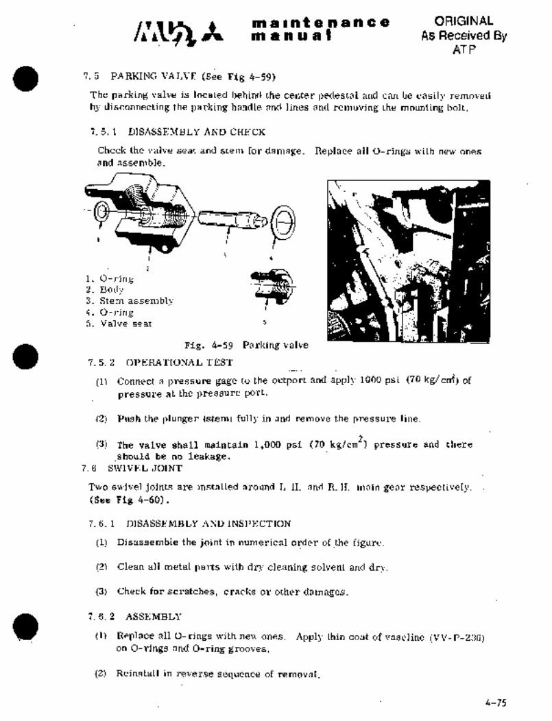
malnaenance ORIGINAL
m a a a a As Received ByAT P
7. 5 PARKING VALVE (See Fig 4-59)
The parking valve is located behind the center pedestal and can be easily removed
by disconnecting the parking handle and lines and removing the mounting bolt.
7. 5. 1 DISASSEMBLY AND CHE CK
Check the valve seat and stem for damage. Replace all O-rings with new ones
and assemble.
i. O-ring2. Body3. Stem assembly4. O-ring5. Valve seat s
Fig. 4-59 Parkingvalve
7. 5; 2 OPERATIONAL TEST
(1) Connect a pressure gage to the outport and apply 1000 psi (70 kg/cniz) df
pressure at the pre’ssure port.
(2) Push the plunger (stem) fully in and remove the pressure line.
(3) The valv;e’shall maintain 1,000 psi (70 kg/cm2) pressure and there
should be no leakage.7. 6 SWIVEL JOINT
Two swivel joints are installed around L..H. and iE.H. main gear respectively.(See Fig 4-60).
7. 6. 1 DISASSEMBLY AND.INSPECTION
(1) Disassemble the joint in numerical order of:the figure.
(2) Clean all´• metal parts with dry cleaning solvent and dry.
(3) Check for scratches, cracks or other damages.
7. 6..2 ASSEMBLY
(1) Replace all O-rings with new ones. Apply thin coat, of vaseline (VV-P-23G)on O-rings~ and O-ring grooves,
(2) Reinstall in reverse sequence of removal.
4-75

C~5 maintenancemanual
NOTE
The washer (4 in Flg 4-60, Detail B) shouldbe installed, facingthe marked side to 0-ring.
7. G. 3´• OPERATIONAL TEST
(1) Condjtioils
Actuating fluid MIL-H-5606
PressureSA
1500 psi (105 kg/cm2)
(2) After applying pressure, turn swivel 5 times.
No leakage sh0uld be detected duringsucceeding five minutes.
’BS
1
2 2
3
i. Union_
1´• Cotterpin2. O-ring -U \~a" \t~r"- 2. Nut
3; Elbow 3. Washer
4. Elbow4. Wnsher
5. Elbow7-
6. Bolt5. O-ring6. O-ring7. Bolt
IB
Fig. 4-60 Swivel joint
4-26 6-1-79
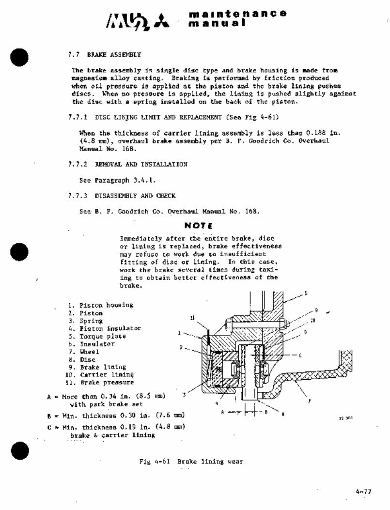
C~bsnalateaaacalaa aaual
7.7. B’RAKE ASSEMBLY
The brake assembly is single disc type and brake housing is made from
magnesium alloy casting. Braking is performedby friction producedwhen oil pressure is applied at the piston and the brake lining pushesdiscs. When no pressure is applied, the lining is pushed slightly againstthe ’dise with a spring installed on the back of the, piston.
7.7.1 DISC LIN_ING LIMIT AND REPLACEMENT (See Fig 4-61)
.When the thickness of carrier lining assembly is Lessthan0.l88 in.
(4..8 mm), overhaul brake assembly pe~ B.´•F. Goodrich Co. Overhaul
Manual No. 168.
7.7.2 REMOVAL AND INSTALLATION
See Paragralih 3.4.1.
j.7.3 DISASSEMBLY AND CHECK
See´•B.’Fi Goodrich Co. Overhaul ManualNo. 168.
NOT E~
Irmnediatkly after the entire´•brake,´• disc
or.lining is replaced, brake effectiveness
may refuse to work du~ to insufficient
fitting of disc or lining. In this case;
work the brake severaltimes during taxi-
ing to.obtain better effectivenessof th’e
brake.
1. Piston housing2.. Piston
3. Spring //104. Piston insulator
5. Torque plate6, Insulator
7. Wheel
8. Disc
9. Brake lining10. Carrier lining11; Brake pressure~
A More t~in.:0.34 in. (8.fj nrm) 13
4
Zwith park.brake set
7
B Min. thickness´•0.30in. (7.6 mm) 832 001
C Min. thickness 0.19 in.’´•(4.8 mm)brake carrier lining
F~g 4-61 Brake lining wear
4-77

CIVjS ~n a i nP a h a a ~C:apn a io a a I
7. 8 BRAKE LINE
The brake line consists of aluminum tube line (3/8 in. Dia. from reservoir to
branch leading to master cylinder, other line 1/4 in. Dia.) installed on
airframe, and flexible tub-e and corrosion resistant tube installed around
main gear leg. These lines are all standard parts.
(1) Do not disconnect lines unless parts replacement becomes necessary due to
leal(age or other damage.
(2) After disconnecting, flush line with MIL-H-5606 hydraulic fluid or
denatured alcohol. Check the threaded section of fittings for damage,the flares fordeformation or flaws, and the tubes for dents and cracks.
Replace all defective parts.
(3) When removing the fittings located on the pressure bulkhead, replacethe washers with new ones.
7. 9 MAINTENANCE OF BRAKE SYSTEM
7. 9. 1 HYDRAULIC FLUID
Use specification MIL-H-560G hydraulic fluid. The total fluid quantity for the
system is approximately 0. 18 gal. (O. 7L), of which approximately 0, 04 gal.(0. 15a) is the fluid quantity in the reservoir.
7. 9. 2 FLUID CHARGE
(1) Remove reservoir line, connect a suitable line dr hose ´•to the line and lead
the line into a container outside ´•the aircraft. Remove bleeder valve and
reducer located at the upper Part of the brake. Connect a hand pump or
test stand to brake body through a union and supply hydraulic fluid slowly.Continue until fluid appears in the container.
(2) Connect the ´•hand pump or test stand to the line leading to the container and
install bleeder valve and reducer on the brake body as original conditions.
(3) Unfasten the bleeder valve and supl!ly fluid slowly´• under a of less
tha!l 14 psi (1 kg;/Z
cm) from the hand pump.
(4) After malting sure that there are no b´•ubhles in flu-id coming out of the
bleedel´• valve, add approx. 0. 13 gal. (0. 5a) of fluid, close the bleeder
valve, apply toe pressure on the pedal (co-pilot side) and~make sure thatis
there is no air trapped.Remove Ihe hand pump or test; stand and connect line to reservoir. Talre
care not to spill fluid.
(a) xeep nuid in the reservorr to the reylar Isvel (miridle of Lhe level gogc). a
6-78
888 ae~Bla 8 a a h 8= 8
iB~ jPb in a s
7. 9. 3 REFILL
If the oil level of the reservoir drops below the end of the level gage, refill
hydraulic fluid ~MIL-H^5606) up to the middle’stage of the level gage.
(1) When it is necessary.to bleed’air during service, unfasten the bleeder valve
of the brake´•and apply toe pressure on the pedal to let fluid flow. Refill
fluid so that the reservoir does not empty.
7. 9. 4 DRAIN
(1) To drain fluid for the brake system, remove the elbow located in the
’lower part of the brake.
7, 9. 5 INSPECTION
Daily inspection can be made by feeling toe pressure on the pedals. After
replacement of components or when sponginess and ineffective brake action’is
detected, proceed as follows:
(1) Remove the bleeder valv;e and connect a pressure gage.
(2) Apply toe pressure on the pedal and make sure that a pressure of more than
G~iil r,r i. (4 2 kg/cm~) is available.
(3) With toe pressure applied on the pedal, pull the parking handle and- release
the pedal to sae if the pressure is maintained.
Check the system fo~external leaks-~r deformation.
(4) Release the.~parking handle, rotate the wheel by hand,´• and i~heck for exces-
sive drag.
(5) Disconnect the pressure gage and bleed airfrom brake.
8. WHEELS AND TIRES
8. 1 GENERAL DESCRIPTION
The wheels and tires: used on.the aircraft are´• as follows:
4-79
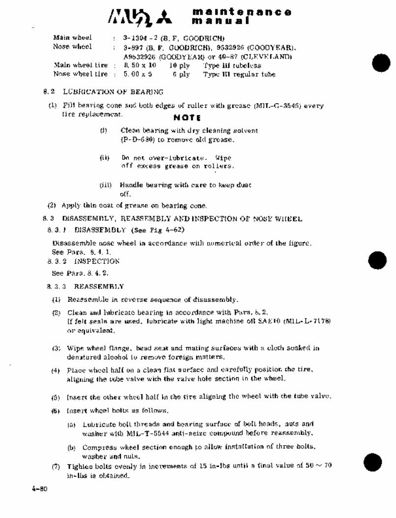
C~iLZ- It m a II nt a II a a a 8III a m a at
Main wheel 3-1304 -2 (B..F, COODRICH)Nose wheel 3-897 (B. F. GOODRICH), 9532926 (GOODYEAR),
A9532926 (GOODYEAR) or 40-87 (dLEVELAND)Main wheel tire 8. 50 x 10 10 ply Type III tubeless
Nose wheel tire 5. 00 x 5 6 ply Type I1I regular tube
8. 2 LUBRICATION OF B‘EARING
(1) Fill bearing cone and both edges of roller with grease (MIL-G-3545) everytire replacement. NOTE
(i) Clean bearing with dry cleaning s´•olvent
(P-D-6 80) to remove old grease.
(ii) Do not over-lubricate. Wipeoff excess grease on rollers.
(iii) Handle bearing with care to keep dust
off.
(2) Apply thin coat of grease on bearing cone.
8. 3 DISASSEMBLY, REASSENIBLI’ AND INSPECTION OF NOSE. WHEEL
8. 3. 1 DISASSEMBLY (See Fig 4-62)
Disassemble nose wheel in accordance with numerical order of the figure.See Para. 8. 4. i.
8. 3. 2 INSPECTION
See Para. 8. 4. 2.
8. 3. 3 REASSEMBLY
(1) Reassemble in reverse sequence of disassembly.
(2) Clean and lubricate bearing in accordance with Para. 8. 2.
If felt seals are used, lubricate with light machine oil SAE10 (MIL-L-7178)
or equivalent.
(3) Wipe wheel flange, bead seat and mating surfaces with a cloth soaked in
denatured alcohol to remove foreign matters.
(4) Place wheel half on a clean flat surface and carefully position the tire,
aligning the tube valve with the valve´• hole section in the wheel.
(5) Insert the other wheel half in the tire aligning the wheel with the tube valve.
(6) Insert wheel bolts as follows.
(a) Lubricate bolt threads and bearing surface of bolt heads, nuts and
washer with MIL-T-5544 anti-seize compound ~before reassembly.
(b) Compress wheel section enough~to allow installation:of three bolts,
(7) Tighten bolts evenly in increments of 15 in-lbs until a final value of 50 70
washer and nuts´•.
in-lbs is obtained.
4-80

m b i in ~e i~ ti a a 8ta an a al
1. Wheel half (Inboard)2. (Outbbard)3. Bearing cone
4. Felt ring5. Snap ring6. Bolt
7. Washer
8. ´•~Nut
5
7 (40-87) 7 8
2,:I4i"i I
871 1.´• Wheel half (Inboard)
I4. Bearing cup3;Bearing cone
2. (Outboard)
:Y..II ´•´•´•:,1 6. Bush5. Bolt
5:rc. 7. Washer
(9532926) 8. Nut
Fig. 4-62 Nose wheel assembly
8. 4 ’DISASSEMBLY, REASSEMBLY AND INSPECTION OF MAIN WHEELS
8. 4. 1 DISASSEMBLY (See Fig 4-63)
(1) Remove. valve core and deflate tire.
(2) Break bead from both flanges by ~applying pressure in even increments
around the entire sidewall close to the tire beads.
(3) Remove b6lts,´• nuts and washers which secure the wheel halves.
(4) Separate the wheel halves, remove tire.
4-81
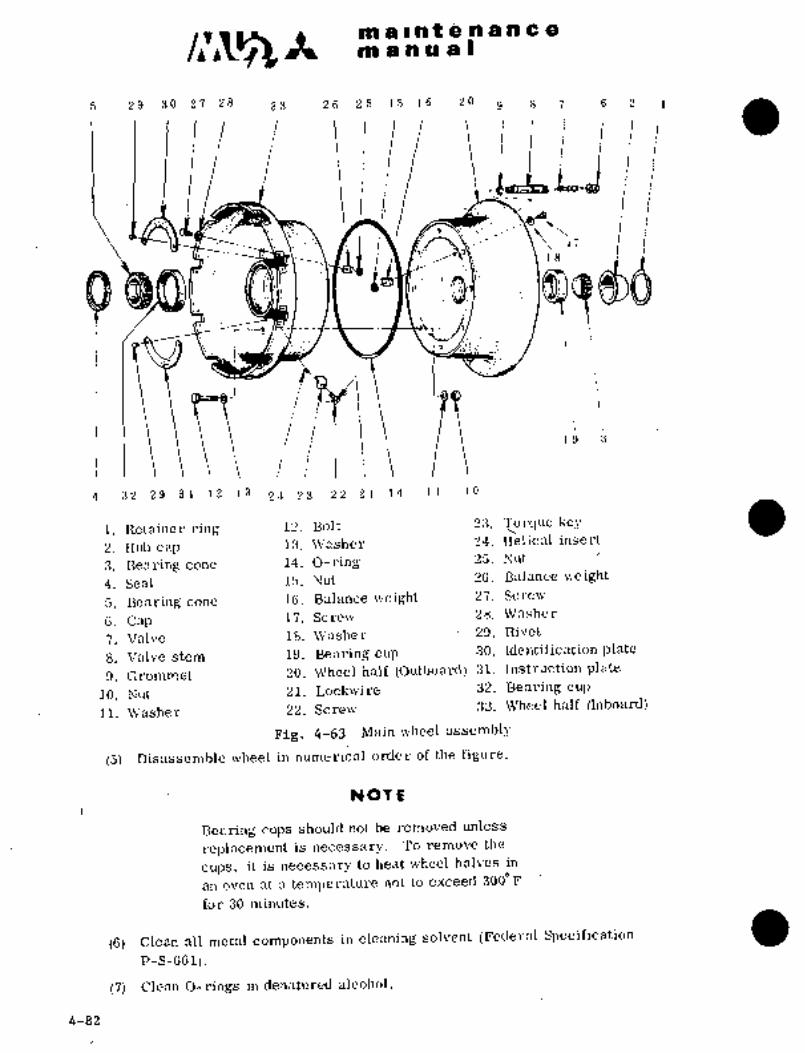
c~smi Ea I ri t e n 8 a C 8
on a a u a 1
5 29 30 27 28 33 26 25 1.5 16 20 g 8 7 6 2 1
Iliij
r.
Ir,
j
4 32 29 31 12 13 2´•2 %3 22 21 1/i 11 10
1. nctainer ring 12. Bolt 23. ~prque key
2. Hub cap l~.´•Washer 24. Helical insert
3. Bearing cone 14. O-ring 25. Nut
4. Seal 15. Nut 26. Balance weight
5. nearing cone 16. Balance weight 27. Screw
6. Cap 17. Screw 28. Washer
7. Valve 18. Washer 29. nivet
8. Valve stem 19. Bearing cup 30. Identification plate
9. Grommet 20. Wheel half (Outboard) 31. Instruction plate
10. Nut 21. 32. Bearing cup
11. Washer 22. Screw 33. Wheel half (Inboard)
Fig. 4-63 Main wheel assembly
(5)~ Disassemble wheel in numerical order of the figure.
NOTo
Bearing cupsshould not be removed unless
replacement is necessary. To remove the
cups, it is necessary to heat wheel halves in
an o\Icn fit 3 teml,erature not to exceed 300"F
for 30 minutes.
(6) Clean all metal components in cleaning solvent (Federal Specification
P-S-GG1).
(7) Clean O-rings in denatured alcohol.
´•4-82

ji~ /ije
la a I.Bat e a g e a
/n
8.4.2.,r
(1) for- cL~ick’S i or btli~kr ~bmage; ctack part~;:Cliebk fSi´• almage b~ if necessary;
~3) 6r c.iie for .irei~hdae oi:.carrol;ion.
i~hOck tha.i~dller retainer foird~idage. ~Repla’ce if ~icces‘sary,(4) ~iie;c´•k tti~ Eiu~b cab local wear. :Replri~e if neces~sary!
(5) thB se~ure the wheel halves fo~ deforina-
trcin~s hni~ cor~osion.. Replace if n~cessary;16j iiepiac6 the nhts fo~ wheel half attachig bo~ts after
ten ti:mesoi ;diSassembiy and reasseinbly or before, should there be
appa~eht deformation.
NOTE
To repai~ the ~niheels minimize the
damage area repaired by polishing.
(7) Polished portions shou~d.be finished per specification MIL-M-3171
Type I andapplytwo coafs.of zinc chro~ateprimer.per specificationMIL-P-8585A. Bearing cup should not be finished with lacquer.
(8) For~repair portions of wi~ich aluminized lacquer has been applied,apply two coats of aluminized lacquer per specification MIL-i-7178.
(9) Spray one coat of zinc chromate primer onholes for the~attachingbolts per specification MIL-P-8585A.
(10) Make sure t~at bead and flange portions of the wheels arefinished
with zinc ´•chromate primer and aluminized lacquer. This is for
corrosion preventive purpose as well as to seal air pressure of
tubeless tires.
8.4.3 REASSEMBLY
(1) Reassemble inreverse sequence ofdisassembly.(2) Clean and lubricate bearing in accordance with Para. 8.2.
(3) If bearing cups have been removed, the wheel half should be heated at
a temperature not to exceed 3000Fand the cup should be cooled at OOF,then reassembled,
(4) Before mounting tire,’ make certain it is free of foreign material,the bead, areas are clean and there is no damage.
(5) Wipe ~Jheel flange bead seat and wheelmating surfaces with a cloth
dampened´•with denatured alcohol to remove foreign matters.
(6) Lubricate O-ring with a light coat.of grease MIL-G-3545.
(7) Place thebrake side wheel half on a clean flat surface and install
O-ring.(8) Place.tire on the wheel half;
(9) Position the outboard wheel half in tire with the red dot at the
valve stem and install the b´•olts.
(B)’~Lubricate’bolt threads´•and bearingsurfaces of nuts, bolt heads
and´•washerswith anti-seize compound MIL-T-5544 before,assemb’ly.(b) Compresswheel section-enough to’allow insta’llation of four bolts,
washers~ and ´•nuts 900 agart and iristall the: bolts and tightenuntil wheel halves sfiat. ~Then, install remaining.bolts, washers
and nuts. Thebolts.should b.e inserted from the´•brake side of’
the wheel.
(c) Tighten bolts in equal increment to a torque value of 190 to 210
incibs. (219 to´•242 kg-cm).
4-83

c~A maantenanceon a a a a I
r
8. 5 TIRE: 70
8. 5. 1 INFLATION PRESSURE:
(1) Main wheel tire 80
(a) Reassembly 60 f 5 psi(4. 2f 0. 4 kg/crX)
Long period of: qs 5 psi 50
storage a
(3.4 f 0. 4 kg/ cm2)
(b) Mounting @o load): See Fig 4-64
40When the tires are on the ground,the tires shall be inflated 4~0 psi
higher than the value in the figure.
7 8 9 10 11 12(2) Nose tire
Airframe weight x 1000 Ibs(a) Reassembly 55 f 5 psi
Long period of (3.9~t0.4 kg/ cmZ) 3.5 4 4.5 5 5.544 it 5 psi Airframe weight x 1000 kg
storage (3.lf0.4 k~crX)Main tire inflation pressure(b) Mounting 55~5 psi(3.9~0.4 kg/cm2)
On ground: 57f 5 psi~4. 0~0. 4 kg/crX)Fig. 4-64
8. 5. 2 MAINTENANCE: AND CHECK OF TIRES
Tires which are worn to such an extent that the treads are barely´•recognizableand those considered unserviceable because of damage should be replaced.
8. 5. 3 BALANCE MARK
(1) Tube tire: Align the balance mark of the tube to that of the tire.
The balance mark of tube is approximately 1/2 in. (13 mm) wide and 2 in.
(51 mm) long. The balance mark of tire is a red dot located above the
bead of tire.
(2) Tubeless tire: Align the balance mark (red dot) of tire to the valve stem
in the wheel.
8. 5. 4 TIRE TREAD
The main and nose wheel tires Should be of the same tread pattern.
8. 5. 5 DUAL WHEELS
In order to ensure the equal distribution of load, tires of the same brand should
be used for the dual wheels (nose gear).When this is impossible, the diameters of tires (inflated), should be measured
to make sure that they are the same, within the difference of 1/4 in. (6. 4 mm).
8. 5. 6 SLIP MARX. (Applicable to tube tire)
To detect tire slip and to reduce damage to the tire and tube caused by wheel
slip, a marking shall be provided to indicate that’the tire and rim are in the
same position. The mark should be 1 in. (25 mm) wide and 2 in. (51 mm) long.
4-84
c~s888 a 8 nt e.n a se a a
P8 a a a 8(
It shall be painted across the tire siclewall and wheel rim so that it will extend
1 in. (25 mm) over the tire and 1 in. (25 mm) over the rim.
Use insignia red, color number 11136 (Fed Std. 595), 3-M red tire marking
paint No. ECL626.
When tire slip is detected after marking, deflate tire and place the valve
in the correct position. Then, reinflate tire, remove the previous slipmark, and paint a new one.
CAUT%ON
Check tire slip mark daily. If tire
slip is detected, deflate tireand correct.
9. LANDING GEAR POSITION INDICATING LIGHT AND WARNING SYSTEM
9. 1 LANDING GEAR POSITION INDICATING LIGHT
The Landing gear position indicating lights consist of three green lamps
and one red lamp installed adjacent to the control switch. Each indicator
lamp is push-to-test type.
(1) Gear down operation Down limit switches are installed on nose
gear and main gears. (left and right)
gGreen lamp illuminates.
(2) Gear up operation ~mal, alllamps
go off.
(3~ Red lamp Red lamp indicates unsafe condition and
illuminates in the following cases.
(a) Gear down operation Main gear forward doors are not closed or
nose or main gear is not in down locked
position.
(b) Gear up operation Nose gear up indicator switch is not set,
or main gear forward doors are not closed,
or main gear up indicator switch is not
set (main gear aft doors are~not closed).
9.2 WARNING SYSTEM
The warning horn will sound in the following cases.
(1) When the control switch is placed to the UP position on the ground.(2) If a Power Lever is pulled back to near FLIGHT IDLE and the landing
gear is not down-locked.
Pa OTE
S/N 652SA, 661SA, 697SA thru 717SA
When airborne, this Warning Horn may be
silenced by use of the Horn Cutout Switch.
S~N 718SA and SubsequentWhen airborne the Warning Horn may be silenced
by use of the Horn Cutout Switch, except when
4-1-78the Flaps are extended to 200 or 400 down.
4-85

c~sap 8 991 f 8 a a a a a
m a! a a a I
9.3 ADJUSTMENT AND CHECK
As to adjustment of switch, see Para 10.9 LAND GEAR SAFETY SWITCH and Para.Indaily check, check
a
10.11 ADJUSTMENT OF PROPELLER LOW PITCH LIMIT SWITCH.
for proper installation of switches and that no foreign material is on
the switches.
10. ADJUSTMENT OF LIMIT SWITCH
In order to perform landing gear operation safely and exactly, 13 limit
switches are used for linkages of landing gear operation mechanism (see Fig4-65). Adjustment of each limit switch is as follows.
io 12I I 6 ~s s
3;1
3
6 7 8 1011
1. Nose genr down limit switch (S105) 9. Landing gear safety switch (5322)
2. Nose gear up indicator switch (8106) 10. Ground door open switch (8921)
9. Up limit switch (8282) 11. Zone control relay (K305)
4. Up zone switch (8283) Landing gear up relay 0(306)
5. Main gear ft~d. door open limit Landing gear down relay (K307)
s\i?tch (5330) Door open relay (K308)
6. Main gear fwd. door close limit switch Door close relay (K309)
(8328, $329) 12. Propeller low pitch limit switch
7. Main gear up.indicator switch (5326, 5327) (5317, 5318)
8. Matn´•gear down indicator switch
(5324, 5325)
Fig. 4-65 Installed position of limit switches
4-86

iP C Riehrin@~iii ii Oil’BP ;Bi i
lo.i NOSE 6E~IR i)dWN (See ´•l’~g 4-66)
(1) limit switch is on the RH keel,nosegear wheel and stopsof landing gear mbtor thrbugft.landing g~ar down relay
aftet gear extension. This switch also actuates main gear forward
door actuator and closes the door.
(2) Adjust the limit switch temporarily so that the switch actuates at
the position where the LH downlock enters more than´•´•0.24 in. (6 rmn)in the groote and~ REi’ enters more deeply. Finar adjustme~t is made
tdgeth~r with the landing gear power train (see Para 4.7).
~71´•
Fig. 4-66 Nose gear down’limit switch
10.2 NOSE GEAR W IM)ICATOR SWITCH (S-106) ADJUSTMENT (See Fig 4-13)
After installation of nose landing~gear up indicator switch, adjustmentshould be made in accordance with the followingprocedures. Retract
landing gear slowly under noload and no inertia condition. Locate the
hinge~lug connecting thelever and Ifnkso that the switch.actuates at.
the position where´•the gear travelstopnut comes within-a point approxi-mately 0.28 f 0.04 in. (7 f 1 mm). to the end of the gear travel. Fine
adjustment of lever position is- made -by the worm gear.
ORIGINAL
As Received ByAT P
’4-87

sn 1 ii’ nP a a a ~ila a
IBI a so a a I
10.3 UP ZONE SWITCH (See Fig 4-67)
This switch is installed on the mechanical stop and makes a circuit to
close the main gear forward door at a moment before landing gear motor
stops. Adjust installed position of the switch in accordance with
Para. 4.1.2.
10.4 UP LIMIT SWITCH (See Fig 4-67)
This switch is installed on the mechanical stop and stops the revolution of
the landing gear motor through landing gear up relay. Adjust installed
position of the switch in accordance with Para. 4.7.2.
i. Up limit
r switdh
2. Up zone
switch
1 Cb
J~a,
iiI: _~
ORIGINALATP
As Received By
Fig. 4-67 Switches in mechanical stop
10.5 MAIN GEAR FORWARD DOOR OPEN LIMIT SWITCH (See Fig 4-68)
This switch is installed on the main gear forward door mechanism and stopsthe door movement when the forward door is fully opened, and also revolves
the landing gear motor through a relay. Adjust in accordance with
Paragraph 3.9.2.1 (9).
4-88

.r :;a~´•
e
I~ liil ii~´•i 88
til a ~i iii iih II
Fig; 4-68 Main gear fwd,
door 6pen~ limit switch
ORIGINAL
As Received ByAT P
10.6 MAIN GEAR FORWARD DOOR CLOSE LTMITSWITCH (See Fig 4-69)
(1) These switches are installed on the door jambs (L, H; and R. H. main gearforward doors, and actuate to stopdoor a~tuator through ~oor’actuator
re-lay.’ These switches are connected
’to "UNSAFE’’ indicating cii´•cuit, to
indicate main gear forward door
(2) Adjust in accordance with Para.closed.3. 9. 2. i. (10)
k?::
10.7 MAIN GEAR UP INDICATOR SWITCH
(See Fig 4-70)
(1) This switch is installed on the LH
and RH door’.jambs, ~ln.gearaftdoor, and actuatedby main gearaft doors which are connected
mechanically to main gear. .Fig,-6-This switch is~donnected to close limit switch
indicating circuit to indicate main gear
up position..
(2) Adjust~ the switch so that the limit
switch plunger may move 0. 16~
0. 20 in, (4. ly 5. 1 ~mm) from~ the~ja
most projected position u3ien
main gear aft door is cldsed.
10.8 niAIN GEAR DOWN INDIi~ATORSWITCH (Se Fig´•~-71)
(1) This switch is installed on the frame
(L. H. and R. H. attaching´•pointof main gear oleo strut, F. STA5605.,This switchlights indicator light:.to Fig´•. 4-70 Main gear up indicatorindicate main gear down position. switch
4-89
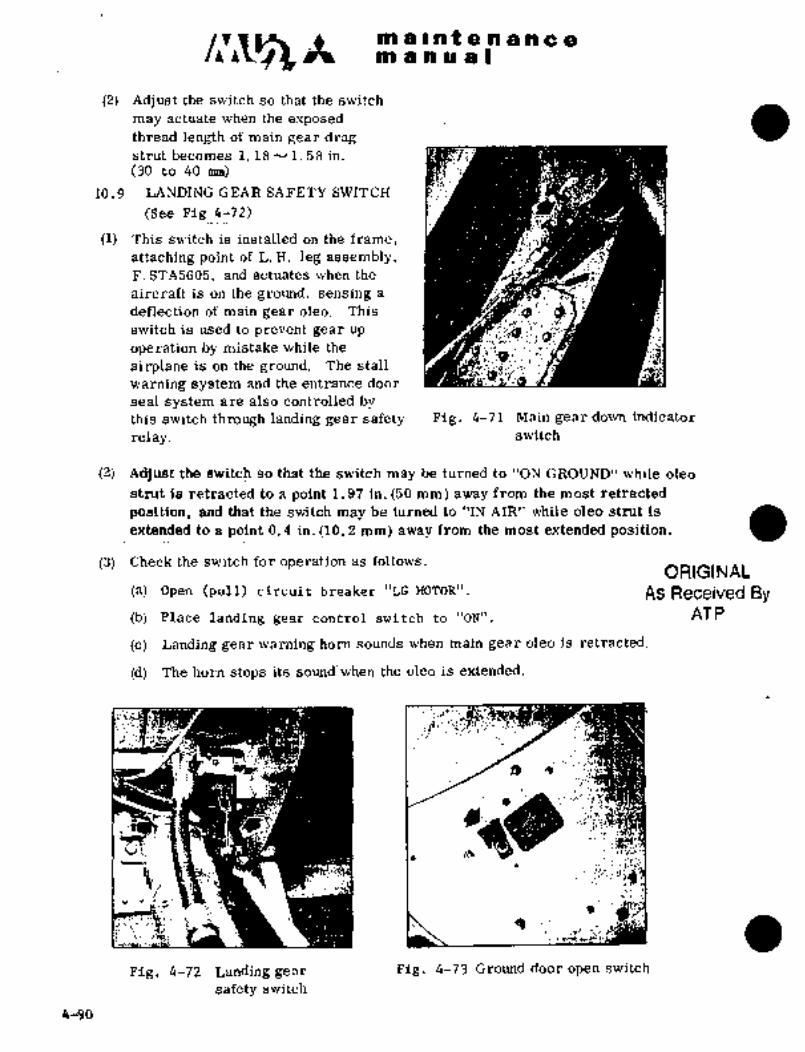
ma~ntenancean a a a a I
(2) Adjust the switch so that the switch
thread length of main gear dr~gmay actuate when the exposed
strut becomes i. 18N1. 58 in.
(30 ~to 40 mm)
10.9 LANDING GEAR SAFETY SWITCH
(See Fig 4-72)
(1) This switch is installed on the frame,
attaching point of L. H. leg assembly,F. STA5605, and actuates when the
aircraft is on the ground, sensing a
deflection of main gear oleo. This
switch is used to prevent gear up
operation by mistake while the
airplane is on the ground. The stall
warning system and the entrance door
seal system are also controlled bythis switch through landing gear safety Fig. 4-71 Main gear down indicator
relay. switch
(2) Adjust the switch so that the switch may be turned to "ON GROUND" while oleoi
strut: is retracted to a point 1.97 in. (50 mm)~away from the most ~retracted
position, alia that the switch may be turned to "IN AIR" while oleo’ strut is
extended fo a point 0.4 in. ~ld. 2 mm) away from the most extended position.
(3) Check the switch for operation as follows.ORIGINAL
(a) Open (pull) circuit breaker "LG MOTOR". As Received By(b) Placelanding gear control switch to "ON". AT P
(c) Landing gear warning horn sounds when main gear oleo is retracted.
(d) The horn stops its sound‘when the oleo is extended.
´•Ii~d
II~ d)
Fig. 4-72 Landing gear Fig. 4-73 Ground door open switch
safety switch
4-90´•

IS t i;i ih C OIn ai~ ii ~iCY I
lo. 1~ GROUND DD~R OEEN SW~’I‘6H (See Fig
(1) ’rhiB Qi~iitdh is instailed on theaft bulkhead if; STk5800) bP R. ii. ~hlge main
gear weli, and i~sed when necessary’to bpe~ mai gear ~brward ~oorfbr.inairitehande or inspection.When circuit breakers "~G CONT" arid "DOOR in circuit breaker
pahel are Closed~ using gro~ind po~ier s6urce or airp;ldne battery, this switch
can open or close the main gear forward dooi-,
NOTE
i’urn th~ circi~it breakers tb "OFF’! so that the
door may not be dpened.or closed inadvertentlywhile vvqrking iri main gear well..
(2): Adjustr~nt:ls. not necessary;
to. 11 ’-PROPEUER LOW PITCIjL LIMIT SWIT~H (See Fig´• 4-74)
(1) ‘This switch:is installed on the engine control cable pulley bracket
near F STA 8035, and energizes a warning horn when-the Power
Lever is moved near tIiePLIGEIT IDLE position. before the landingge~ir is in the down-locked position..
Actuator roller
ORIGINAL I II: -(~s$ t C
As Received ByAT P \-Switch
Rigpin hole
A A
Pig. 4-74- plopelley low pitchliinit~ switch
(2) Adjustment
(a) InstciIl the switch so.thatthe switch may be turned to "OFF" at the
condition of´•A-P;:hoivn~:inIn-Fig;, -~Z;24 a~id that the switch’ may be turned to
"ON" when.the highest pbint (a) of pulle~ side cam~ Comes to actuator
roller position.
4-91

mallntenancemanual
(b) Install the switch at about center of long hole. When the switch
is moved to fhe direction of arrow "C" after loosening screws,
the switch comes "ON" at the condition which power lever is near
TAKEOFF position. Adjustable amount by long hole is approx.
f 90 on power lever in the center pedestal.
(c) Make sure that the landing gear warning switch comes "ON" at
about 0.2 in. (5.1 mm) before FLIGHT IDLE position when power
lever is moved to FLIGHT IDLE position from TAKEOFF position.
11. EZ~ECTRIC CIRCUIT
Control circuit of the landing gear motor and main landing gear forward door
actuator is through the circuit breaker LG CONT. Powerlines to the landing
gear motor and the main landing gear forward door actuator are protected by
independent circuit breakers LG MOTOR and DOOR ~OTOR. The landing gear
position indicating light circuit is protected by an independent circuit
breaker LG POS. The circuit diagram is shown in Fig 4-75 thru 4-83 by each
phase, i.e., the landing gear in downlock position on the ground, in re-
tracted position, and extended position.
4-92
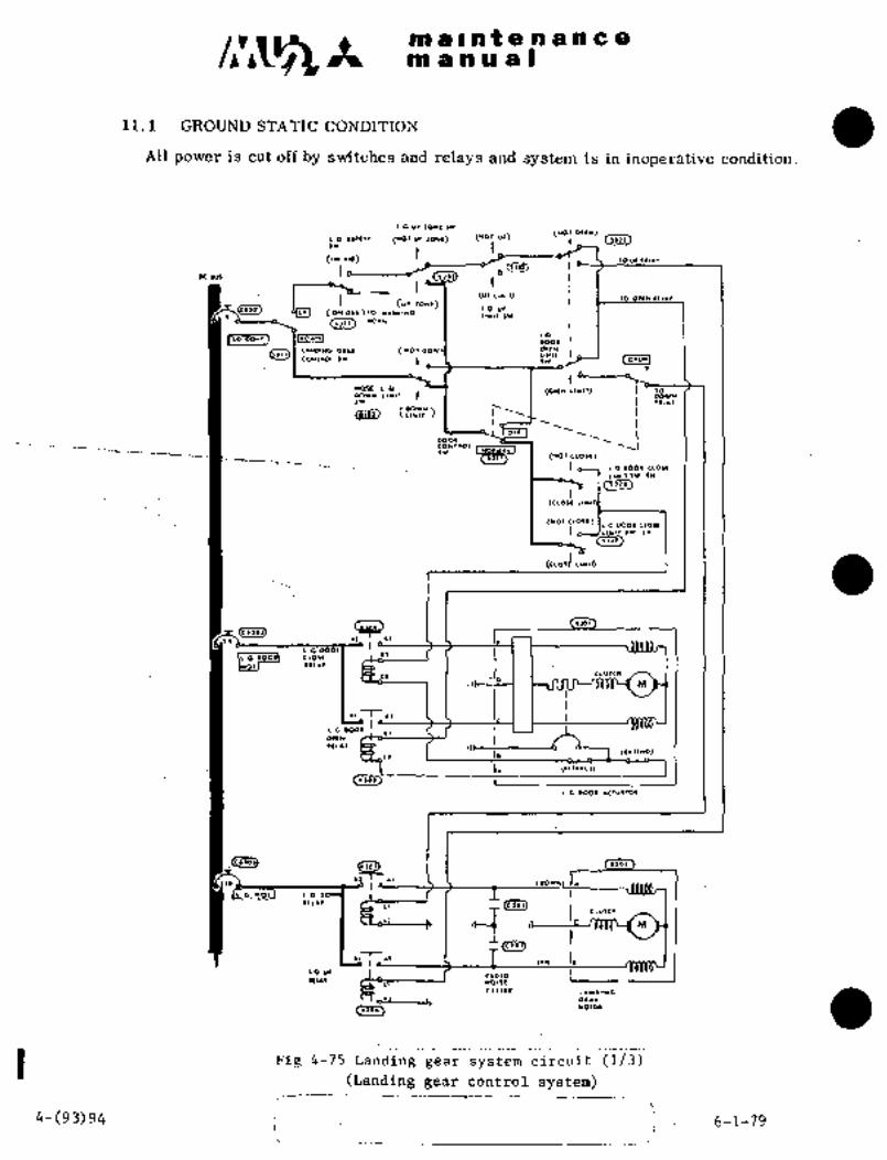
maintenancemanual
11.1 GROUND STATIC CONDITION
All power is cut off by switches and relays and system is in inoperative condition.
i cu~ lo*e w
(1101 U! 10*1)(WQ1 O,t*)
)~11
(IN~´•I(J rOUII((´•´•l(1111)
#M
(U, Ltrll) Ot(N 11(1**CUI IOW()
IO UI)01 (011010)10 YIII(IWG1I*I) IW
(1)11) *01*
I LG ,,t, IDO1CII IO,I~
LIND’k"’U (1101 ~LNLI*ll
lortu]OONllOl )11 )11
NOSE L4 (01111 IIYI~ 10DD1W Llltl 03WN
II~´•´•
(0011114
orr
DOOI
LG 0001 CLO)I
(Iiis)
(CLOII L
(IG 0001 CLOII
LI*llr)l LI(
()~I´•)
(CIOI~ L"’d
8´•~.1)C;i~3I ~ol
i,
´•I clurcr
~I M
LGDOQ´•
OIIYI)L´•l
11 IO (llll*D)
I,<´•101) 1
LG D00l ´•CIUIIOI
L(CI~ ~,03 1 I(DOI*) I´•
I1 G *011 L.G
111~´•,I cio
´•´•i M
I r~* I111*1
I~ wolcli ’L"’ LLNO1UC
1l 1. 01´•1
c.sai)110101
Pig 4-75 Landing gear system circuit :(1/3)
(Landing gear control system)
4-(93)94 1 i 6-1-79i

maintenancemanual
(LI9OI)
<f’’fl *cl*lo.,
r,lc* 99 (LO1)
ICre(
sw
91199 (LOr)
S/N 652SA 6 661SA Unless Modified By SR015/32-002
LO Il~l*Q *0911
(tllO) *CI.IO)O CUTOUT O´• I Lor~l*llomw*
~4.. eLII
990, ~or91799 CI
alo*l 1 ’7 ~o r~a*lrm
d ´•I( sYlOur I1LL´•I
COY
L*rl)OPLO´•
(LO1I
SIN 697SA Thru 717SA Unless Modified By SR015/32-002
Fig 4-75 Landing gear system circuit (2/3) ~(Position indicating system)
4-(94A3 94B 6-1-79
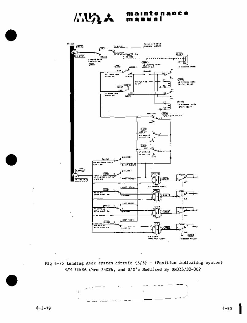
clr~smallRf 666666
man uzsl
oo suI rO LO 1TI000*
(L.2O1).201 ..fOU"OL SIIlEY
"I"""" SrOl
Co*lan Ir~,ldL
tim.)LO VIRWI*O*OIW
DOIIl
CINOI~ OL´•~
(tals) ,ctnlo~l CUTOUT sr I
cow _J*o, I
aH PROP LOI
rlteu su cLOI, I I 1 a
xiTO rL´•’ )I LG 149111*0 ~011(
11O´•I IEVIYIL RLLI*O(IOHI
Osid IC
EOY ~J I I _*
LnPaoPLov a~PITCH SW ILOll
*1
r) Fl~g)LO WIRWI*O WOR*
)II~ CUTOUT IELI*
Iwor UP, 0106)s_ HOSE LO UP IND SV
(UP"I"
(sa29
IrOT UPI
RH Yl(n LG
UP INO 511
(00)
(rs?d
UIIN LP
YP IND SI P~ICLOSEI IUP)
(sala)
r(H YL6 DOOR CLOSE
LIUIT 31 -~(WOICLOSE)
(csnoJ~ I _elcLOSrI
(gSZp) IU*1ITEIU*1ITE
3b P lbLH YLO OOQR CLOSE
POS INDI ILIYIT SI ~)INOT CLOSE I
LG UHSIFE LIGHTJ(WOT DOWNI
I Inosr
POSE LO IPOIN LIUIT II
I
Ilror WVN)
aRn
an Y´•IN LO \Z IWlw LIUIT )W tlODY1*l 1 10
all
I(WOI DOlll
(sji3) ILH
LH Y*IN LO
Z(DOIU) -I-I I\-ICe~wOnr L1YIT LLI
las
~aLO DD1*
I*DICIIOR LIOWT DIYIIWO RLL**
Fig 4-75 Landing gear system circuit (3/3) (Position indicating system)
S/N: jldSA thru 730SA, and S/N’s Modified By SR015/32-002
__I
~I
6-1-79 4-95
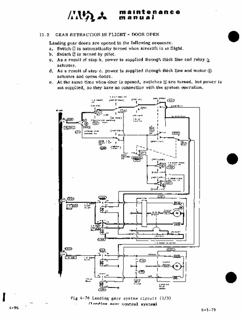
ma~ntenancem a a a a I
11.2 GEAR RETRACTION IN FLIGHT DOOR OPEN
Landing gear doors are opened in the following sequence.
a. Suritch O is automatically turned when aircraft is in flight.b. Switch O is turned by pilot.c, As a result of step b, power is supplied through thick line and relay
actuates.
d. As a result of step c, power is supplied through thick line and motor
actuates and opens doors.
e. At the same time when door is opened, switches ~are turned, but power is
not supplied, so they have no connection with the system operation.
IG UIIQYllr,
(1101 UI 10*1) (YOI OI) (NO1 O)(N)
t(IY 1I1) ’OU´•lll´•*
~1)17)
DC ,U)
---C I (Ulllllr)(VI 10111)
IG UI´•101 (O*GID)IO WI)C(IUO LI*ll
~O (1111) *ol*
Ile CONI I (001UI100001
L´•NOIIIG 0111 (1101 Otl*LI*l1
[orlwltO*~I(X )11 Ir
11051 L.O (011*DOrw 1I*I~ ODr*Ir i I I llc´•r
aDoo~
ri;o’ii~tii7("O’ CLOIl)
(CIQ(I
(1101 clOll)ILG WO. CLQI~
(1)11)))1´•
0’(cto,l LI*lr)
i ~oi
´•(,II
11 I, c~urc*
~I M
IG
OII~
lo (Iiiiuo!
4/1, (r´•11´•´•((1
(llOl) I~_
L 0 DQO1 ´•C1UIIOI
I 1 (1)01
,o ;DOr*~
I~ 0 *OII ~G
iIc~u,c*
111´•´•
´•~Dlo
~v* II iI´•I r011(
1 II111 LI*DI*CI) 01 11
(´•leil*OrO´•
Fig 4-76 landing gear system circuit (1/3)
oPnr_cqntrOl system)4-96
6-1-79

a a t a a a a a
mamual
U.l,o~
811n wc*lor,
C~C* (LOll
~M1
CV70JT
rlrcn Ir ILD11
S/N 652SA 661SA Unless Modified By SR015/32-002
to n~I*8 m)*I(s,ld r(*IOUI CUIOUT IY 1 18´•11*14*01*
E~’94eLPC* ´•ror LQI
´•ncn
*I
(11~0)~o r*~wl*o ~oel
.I.IC cvrouI ILLII
COY
ILOI)
S/N 697SA Thru 717SA Unless Modified By SR015132-002
Fig 4-76Landing gear system’circuit (2/3) (Position indicating system)
I 4-(9an) she 6-1-79

c~ It´• malntenan~emanual
00 888 10 LC lrr D0Oa
(CI)OI) .CONIaOL 1181111
i~ oNoilLo 851111 sr (rsSoi)ILo coNrl
O
ImwrlLlNol*o oc*aconraDL lr
(8111) LO WI..INO nOaNDais) wclnloac cvlout Sw I Lo´•x~aul*o*oa*
Cou -J ~s
wo Ian raoP ror
rlrc~ Sv n
(1155)XI10 TL*P?III
RTVIVIL I)ELn
LO Ylr)*INO *ORW
(~0´•IIHlOnl
(8511) uC
cou I I I A)
LWPI1OP.LOW ,NOI I i YPIrEH SI (LOII
II
(rl~BLO WIRNI*O WOllll
11 o~ CUTOUT RELI*
(NOI UP) (8108)8_ NOSE L8 UP (ND 51
cUpSb
(5128)
(NOT UP)
RN UIIN LG
UP IWD IW
IUPI
(8511)I
Ln YL~IN LO
UP I*0 811
81810881
(8518). 1_ O (up,
Rn YLO BWR CLOSE
LIH17 81 S(UOT CLOSE L
$elO~7) I _~rCLO.L)
1
S1 I -´•´•-isLH YLO DOOR CLOSE
rOSI.DI ILIUITSI -)IIIOTCLOSEI
LO U~N;I;E\ L)bnlS(HOT WI*l
NOPE
NOSE Lo 1 I
oow* LIYIT 6\*´•(DOYN) 1 1´•
IIIIOTWVII) I I
(r~aw
an YIII1 LO ~P I I~lt
8011 LIYIT S* p(DOyn) 1 10
III
,Y\ ´•I
I INO~ WYIII
(SSES) a
Lt( u´•lN LO t
DO~ LIYlr.lI(DOI.)
aa
1. (r,nOL’ oov*
IUDIC*~OI LIDn~ 01810150 aELI*
Fig 4-76 Landing ge$r system circuit (3/3) -´•(Position indicating system)
SN 718SA thru 730SA, and S/N’s Modified By.SR015/32-D02
6-1-79i_ i 4-97

c~smalnQenancemanual
GEAR RETRACTION IN FLIGHT GEAR UP
Landing gears are retracted in the following sequence.
a. When doors are fully opened, switches Oare turned automatically.b. As a result of step a, power is cut off and relays O become inoperative and
door opening operation is stopped.c. As a result of step a, power is supplied through thick line and relay O
actuates.
d, As a result of step c, power is supplied through thick line and motor
actuates and retracts gears.
e.´• At the same time when gears begin to retract, switch O is turned,but power is not supplied, so it has no connection with the system operation.
LG U) 10*1 )r
L.C I~1(1* (1101 VI 10111) (UOt U´•) (11010)ILIJ
(111 ´•n) lOvt
"W
(Ul LI~lr) I 10 Ol(..n´•~G´• 10*1)
(O*GID)IO WIINI.G
I)111) *01W
i,, tu~ loov*l
(11l1) LIllDlllOOlU (1101 O~I*LI*ll
lotlnlcOlllla ,r
NOSE I.(i ~0´•IN LI*lr) 10bOlH 1I*I1Ir In´•~
(PP~,
o´•, I Iooo´•
)11(wo~ CLOII)
L.t D001 CLOIILI*ll)*l 111
(clou I
(*or c~o,e
(11
(c~osl
--4~L--I,o,´•1~ I I, r]
~e ooolrl G 00Qll CLO)I
IrotT
I lo I I rC~*
O
le oocl
Ollu
lo
I. (I~n.Ct)
Cllol)Ilol
i G D001 ICIUlrOl
cc~ I I Cllo,
(oer*)
I1o uoil Lb
I~LLI´•I
M
~101]
iI.o ur (1) T Ilolo
Vr .71 *oi~l1 Iirii L´•*DIIG
01~1
Cl~oi)’1’ *0’01
Fir: 4-77 Landing gear system circuit (1/3)(Landing~ gear cont_r_o~y_stem)
4-98 6-1-79

c~sst m a i a t a a bi a a 8manual
61,o~
Icc*ra*l UIII*I*OYO**
COY C´•1~ ~aor LOI
rlTcn Cr tror,
tvran
CC~J) sw
,wrao.,o´•rl~c* O´• tLOY,
S/N 652SA 661SA Unless Modified By SR015/32-002
(i~,oi)
(IIOI)LO 111Y1*0 1(0111
~Tii) ICI.IO*) CUTOUT .Y I LO´•´•.114YOll*
cOu 9 eL~
~or LO1(LOr)
.I 94)44)
LO 1´•1*1*0 wol*
94111) CUTOUT IELIT
9CITCH
S/N 697SA Thru 717SA Unless Modified’By SR015/32-002
Fig 4-77 Landing gear system circuit´• (2/3) (Position indicating system)
4-(98Aj 98B 6-1-79

c~s It mallnte nance
manual
oc IuI ’m LOlil D00.
(CaIOI) 5’011211
i01~101110 11´•~1.LO CO*T
IMv*lLIHDIYG OLIR
COWTIOL I1X(IX)I)
(5212) Lo WIRHIIla HORN
6~11) HCIHI.H) CUTOUT (W LO VIOYIII. PORN
IICou _J LL-LS
HO II1(1( PPOPLOW
PITCH sW rrowl a
xi
TO
rrc~Lb IIRIIIN6 110011
(20’1 IEVIVIL RELI*(HIOWI(IIl1) re
Cou I I I _u
taraoprol i. Irlrcn sr (LOll
Al
II ("’I0)LQ *IRHIHG HORN
Il II( CUTOUT RLLII
IHoT UP,
WODELOUPIWDI*
,,p9a
(sug
Iror
iaH YIIH LG
VP INO 5V
(110)
(53262
LW Y1IN LO
UP IWD IV
BICL)SEI I (UP)Csa?8)
T_
P
RI( YLG DOOR CLOSE
LIYIT 51 CLOSEI I I
(CIlO)I) OICLOSEI
1_ rjnslrrI -´•´•´•I~
Ln YLG DOOR CLOSE
POI IWDI I LIUIT SV ~O(WOT CLOSE I
bl´•
Lb UNSI~FE LIGHT~INOT DOYW)
b~ I*01EJHOSE LO IDov* LIu,T tw
elDOWnlG
11HOr DOWN)
3laul
I* YIIH 10 12 12
WN* LIUIT SV .(DO1N) I´•
i all
IINOT DOIW)
C~ aIL HI
LI(YIINLQ 2WIW LIIIIT SV
21DOWll) I(I~
LO DOWN
1WDICLTOR LIGHT DIYYI*O I)LLII
Fig 4-77 Landing gear system circuit (3/3) (Position indicating system)SIN718SA thru 730SA, and S/N’s Modified By SR015/32-002
i
6-1779 4-99
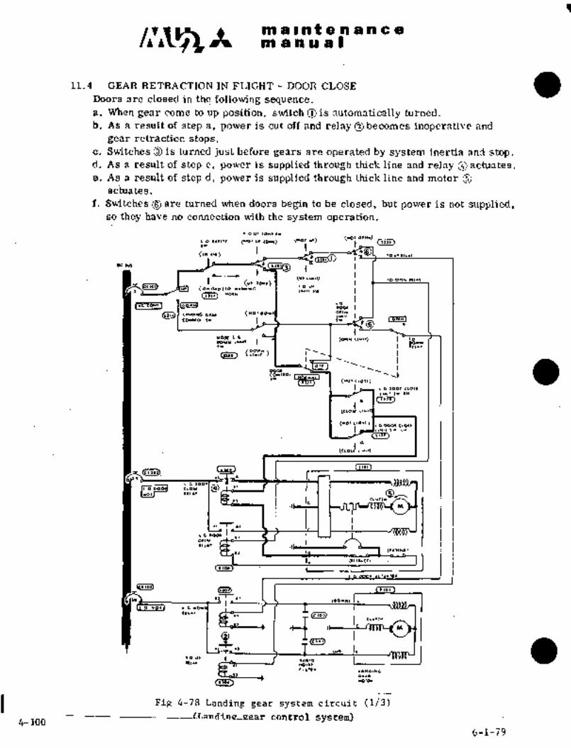
888 a Int a a a a a a
m a a a a I
11.4 GEAR RETRACTION IN FLIGHT DOOR CLOSE
Doors are closed in the´•following sequence.
a. When gear come to up position, switch O is automatically turned.
b. As a result of step a´•, power is cut off and relay O becomes inoperative and
gear retraction stops.c. Switches O is turned just before gears are operated by system inertia and stop.
dt As a result of step c, power is supplied through thick line and relay actuates.
e. As a~ result aS step d, power is supplied through thick lihe and motor Oac’tuates.
f. Switches are turned when doors 6egih to be closed, but power is not supplied,so they have no connection with the system operation.
Ic 111 lo*l ~r
I O I*)Ir’( (1101111 IOHI) (WOr U;) (1101 OII*)
111(1111)1111
(IW ´•I.) rCZii3j~III
(111 1I*I1) 1 10 Ottu
(ONGID)IO II1YIYG
(1111) "O~W
IIG CO*1I IDOr*l IB,I~ L’nDlucclu (WO’ OIll*
tO~l)Q I L Ir i O,i*]t8
!-b81.I I I II~´•*´•
011
DOOl
(’OIIIPY)i
(CLOI( L
(1(01 ~LOlt) (IC D001 CIOII
L*
cFi~i) C~ --~L----1. r
LG D001
I(,´•´• OI, I,
*1 T .1
Otl*II~´•´•
Io (lllll*D)
1.[I,b~
I (IIoi
´•G *011 L-G
-i M
(clo~
´•1
(~010
(u* II Iiou´• I´•II´•´•
1I w01,(11I,1I
I~*gllrOI,
L 01´•.
~Tar) 110101
Fig 4-78 Landing gear system circuit (1/3)
4-100---------(r´•sndinepear_control system)
6-1-79

maintenancemanual
(S~i) LC(*IO*) I Ur´•il*,*O*a~*
eOY
raor ror
ClfCH ~1
~CBeNT(XII
(L~
r,rc* ~r
S/N 65258 661SA Unless Modified By SR015/32-002
Bl10l)
~les)LI I´•nl*0 *01*
~ii) rc~*lo., curovr I Lorrlll*a~*
~Lo
el( rlor LO´•C(r6n I´• (LOll
~Ito r~a*lw, *oa~
n’C( CUTOUT ICUI
LIOCLOIC(ICH
S/N 697SA’Thru 717SA Unless Modified By SR015/32-002
Fig 4-78- Lantling gear system circuit (2/3) (Position indicating system)
r~"P
4-(100A) 100B 6-1-79
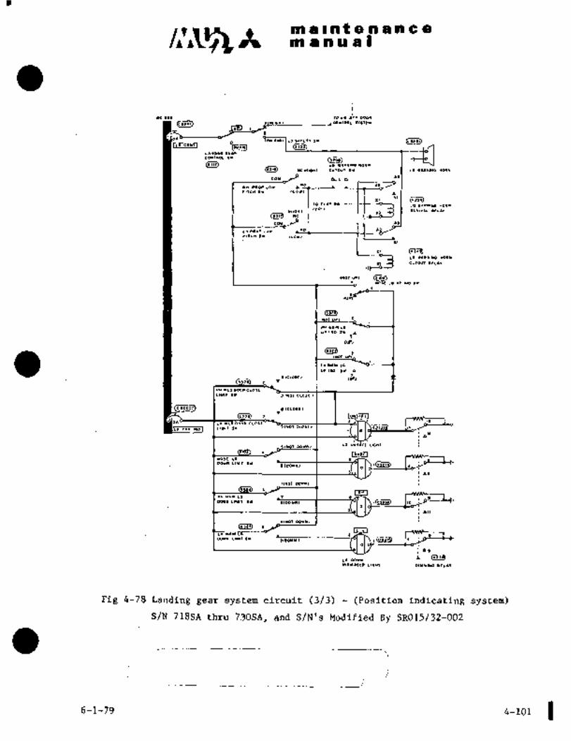
h mallntenancemanual
ocIuI rolI ~rl COOP
Bslo~ m*~1111 .coNllOL Irl,rw
ION o*oll LO IlrLI~ II1
ILO CO*~IO
(~))1)
LI*DI*O OE*OCONrROLIItos(9911) LII IIP.INO HO.W
O11~ WC(~IOHI CUIOUt IX I LOYIRNI*O *M1*
cow ~Y ois _’"*O I ct
RH CROP LOV
PlTCn 1~ (LOII
xi
10 rlIP 8*LG IIRUI*G *05*
(90’1 REYIVLL RLLIIIWIOWL
(9111) PC
COu J I I 1 R1
LI PROP LO1 ,NOI 1 1 YPllCn sI ILOI)
*I
II (1911)
LO YIR*IIIO ~IORn
CUTOUT IIELII
INor UPI (SIO~I NOSE LO UP IHO SY
(slzd)
UP,
RY U1I* LC
YPIND ZY d
(90
(sal~2
IWOT UP)
LH Y´•ln Lb
UP I*D IW Cc
~ICUIIEI (uP)´•_
O
RH YLO COOP CLOSE
LIYIT 9W I(*OT CLOSE I
(C820~ I)(SLDfC)C82O11
(i~ I
I,,
UHSIFE
LH HL(I DOOA CLOSE
PQ.(NDI JLIY)TJ*´• ~OIHOICL05EI
LG UNB*FE LIGHTIIHOT OOWN)
I LNOSEINOSE LP I 9 B
I(OOVWI I (IbDO1N LIUII (V
II
1(1107 WVNI
3LR*I
1)1( YIIN LO I 9 IZW1IILIUIT 9’9 911091) I(CSPlb) )O
hll
llllOr DOVUI
(1111) 3
L.I1IUL.
COIN LIYITIW1(DOI.) I(e~
!aiL (1914
LO DOWN
IWDICITOR LIOH7 DIYYIYO REL**
Fig 4-78 Landing gear system circuit (3/3) (Position indicating system)
S/N 718SA thru 730SA, and S/N’s Modified By SR015/32-002
6;1-79 4-101

1
ma~ntenancema nual
Il, 5 GEAR RETRACTION STOP IN FLIGHT
dear up operation is completed in the following sequence and all power is
cut off by relays and switches, so the system becomes inoperative.
a. S~itches Oark turned automatically when doors are closed completelJ1.b. As a result of step a, power is cut off and relay ~becomes inoperative and
door closing operation is stopped.
Ic u, lo*twtwOt O)IC1)
!O I´•1I1* (1101 VI 10*I) (*O: UI)
´•1)) 10 y. III´•*
~ctu,
h.(UI LIYI1) 10 OI(*
(UI IoNI)IG UI
(OwclD)´•O u*lr lw
(1111) "01*
ILC eat 1 loor*l~o
~e eat oool
(*O’ OII*L1r11
IO)INIEDNIIO( )I Iw
nosg L.4. (O~tN LIrII) 10DQr* LIrll oOw*Ir, I I I
ooal
~G D001 ClOlt
(1)11)1)11
(cloll
(*or CLOIIJI O D001 CLOLLIl*,r)l L*
Ii/N)))P
t~3 (lJOI)1 JOI
<C~)O1)r
,I:´•´•
I, I, ,,,1,.
.I M
´•1 7-´•,
I 0 0001~QII*
111´•1
11 I _ID (Ilrl*D)
I.(.)OI) L
I.o wol ´•c~u´•ro´•
~.101) 1 I (l101
(oorr*)
I.o ro~i L´•G
´•111´•´•1
1 "i M
iloO
i I lu* I~,o ut´• Ie~u *ol,e
1 II1II
11
rotor
(1101)
Fig 4-79 Landing gear system circuit (1/3)
(Landing gear control sys;4m)4-102 6-1-79

mainienancem an a a I
(LlCO))
O,lr) ICtwlo*~ I UI1.*(UP*Q*I
OlrsnCY c~or,
Klb(
1)(10)()cvran(Illr) 5w
(si~8,t~or,
S/N 652SA 6 661SA Unless Modified By SR015/32-002
Blt~i)
LO 111*1*0 1011
eL.*1~
COY
´•H 0000 LO1
´•Itt* C´• (LO1)
´•I
(*10Y1 10 ~1IYI*8Cslli) curour .LLII
S/N 697SA Thru 717SA Unless Modified By SR015/32-002
Fig 4-79 Landing gear system circuit (2~3) (Position indicating system)
j
4-(102A) 102B 6-1-79

maintenancemanuall
D~ sul 20 Ls IPI Door
rsc.
I*IlrY
to. o*O, I LO IlrLI* IY (LIIoI)ILs C041
O
(I,al)
Ls COl(r ~3 (1a2ilwrYw
L1*DI*a or´•l
COI1TIIOL )I
LO YL.UINO *O.*
Oats) .*C(YIOH) SUrdUI II LO ´•´•R.1110 WO(I*
1)cou_J elP
11 s.0. LOIii
PITCII BI a
ri
to rLIP 51
.E,,
LO UII(*IUG IOR*
(~0´•IInlOW)
(jJ(I) HC
COU
,´•i-__-_:_-1C~a-P"rIrCN BY (LO1I
*I
LG IIRUIRQ *ORW
CUTOUI ILLI*
LIIOT UPI (Siij~NOSE Lb UC I~O BY
(saPB
twOr UP
11 Y11 LO
UP INO IW
(1))
(1122)
INOT
L~ UIIN LO
UP I*D 51
sICLOSE) I (UP)~310) 7
RH YLO WOR CLOSE
LIYIT SI ~II*OT CLOSE I
slctosc,2152
(IIIS) I IUNZIIEJUNZIIE
t ISLn YLO DQOR CLOSE
´•POslnol IL’U’rlY I(*OTCLOSEI
14a
.(HOT DdWUI I LO UNSI\FE LIEWI
slOI I INOSE]NOSE LO )1Ch
DOYN LIYIT BYsIOOYYI I@sr~
I to
I aJ´•
IlrOr OowN,
b~ I I L~JRn YIIN LG 1 I ii
om. LIYI~ .*r -iTD~UT I(D021.1 ID
all
I(NOT DOIHLI
(SIlS) ILH
LIl wll* La 2 I
WI* LI*IT bY 21001*)i
as
(rll6LO DO**
I*DICITOR LIPH~ OIY*IYO
FIR 4-79 banding gear system circuit (3/3) (Position indicating system)
S/N:718SA thru 730SA, and SjN’s Modified By SR015/32-002
~-1-79 4-i03

manualmain tenance
11.6 GEAR EXTENSION JN FLIGHT DOOR OPEN
Doors are opened in the following sequence.
a. Switch O is turnad by pilot.b. As a’ result of step a, power is supplied through thick line and relay O
actuates and doors are opened.c. As a result of stepb, power is supplied through thick line and motor O
actuates and opens doors.
d. Switbhes´•O are turned when doors begin to be opened, but power is not supplied,so they have no connection with the system operation.
IG UI 10*( 11orllr)
:~G (*0r Vl’lOnl) (UO:~ut) t Ill,
(iu ~O v´• lu´•.
Dc w_
h(11 Llrlr) (O OI~U frill
I~ UI(ON G´•D)IO YIIN)IIG LI*ll IV
O *0´•*
tG
I LC COw(l elDJ"NI 0001
(1,11)(U01 DO orIN
Iiwtrlo,i*l
)r ii
HOSE Ltt~ (01111 II*11) 10DOr* M)Vm
)U i I I 11I´•1
(DOIN)LIIII
O11
coolco*rlol
3 (*0’ CLO")
It DOOI CLoII
(ClOlt L
(1101 ooo, cIoIe
LII11(II L*
(cLolf LIII1)
(1)01)1)01
I C 000´•I I
999JlP~1I, r
I~ooooll rIO,r
Iro~l "I" /n´•’VIt I, ,,,1,.
.I M
´•I I lI
I C 0001)
o´•IN
Itl iiI io It´•’1*o)
I, (II1I.C1)
<1 toil L
I c oaat
(001111)
II o _rorI ~G
~ci11111
M
C(’04
~b I,´•’ I tu*ass~ IIto II1
111I´• NOI)(
LI*DI.G
L I. CI´•l
11105)rotor
Fig 4-80´•Landing ~ear system circuit (1/3)
(Landing gearcontrol system)4-104
6-1-79

C~5 It m .a~ntenancem a a a a I
~5;i) Ulll.l;b*o~*
~O.LOIc~
rlrcn I
UclOw)(111~ Sw
rl~cn
S/N 652SA 6~ 661SA Unless Modified By SR015/32-002
Q~toi)
~iras)LO Ill*l*P*OII
u ´•U*4 *OI*
eLg
I ~I´•0)4(14)() L(OIII
S/N 697SA Thru 717SA Unless Modified By SR015/32-002
Fig 4-80 Landing gear system circuit (2/3) (Position indicating system)
1-(104A) 104B 6-1-79

c~3 It maintenancemanual
55 IUI 1O to Irr oooR
(55101) 5(1* 1IRI IIITLY
~r
ic* oro,lLO 5511115’5i (LIIO()
-~3 1 cji~
I´•wawo orIR
cowTaoc tr
05112) LO IIPNl*O nOll*
(IItI) UCrHIOH) CUIOUT II LO IIP*lUO WQO*
cou J [U9
*Dr(* PROP LO1
II 1101)1 -11
C*.nOTo rLIP 01 LG 11\9UI*G *01))1
120´•1 r(LVIVIL IIEL~IIrWIOWL
(s~ld r_e
cou
LWPOOP LO1 ,101 1 I 12
PITCI S1 ILOll
*I
(riiolLG YP.RNIIG 112511
Lt o( CUTOUT RELII
Iror UPL (5105)s_ NOI LO UP I*D 511
(5126)
INOTUPI ’1
I* Y1I* LG
UP IIYD 511
IUP)
(5521)1
INOT UPI
LH UIIN LO
UP 1115 511
s(CLOSE)(110
(5118) (P
RI( YLO COUP CLO?IE
LIUIT 5V IINOTCLOSE)
(C52052) .IELDLEIC52052o
L´•´•..~.lis
(5525) I UHS*FE
-T LH YLO COOP CLO5EINOT tLO5EI 0521
POI 1101 1 LIUIT (rY RI~
Lb UH56rE LIGnT5(102 wwN,
~J T*O5E LO L
DOWII LIYIT IVs(DOYWI l(es~3
G
as
IluoT wwwl
(5525) 5 lr r IRHIRn UIIN LO 1 1 12
DO1N LIYIT II iTO~i I(o52ls) IO
1(122 OOYWI
((IIJ) 1IL HI
LII YIIN LO
wu~ LIUIIIY nDbl.) Icp~oi,
as
i Irrns)to oovw
I*D)C*TOR LlOnT DIYYIYB REL**
Fig 4-80 Landing gear system circuit (3/3) (Position indicating system)
S/N 7188A thru 7308A, and S/N’s Modified By SR015/32-002
J
6-1-79 i4-105

m a In f a a a n’C a
manual
Landing-gears are extended in the following sequence.
11.7 GEAR EXTENSION.IN FLIGHT GEAR DOWN
a. Switches O are automatically turned when doors are completely opened.b. As a result of step a, power is cut off and relay Obecomes inoperative and
door opening operation stops.c. As a result of step a, power is supplied through thick line and relay O actuates.
d. As a result of step c, power is supplied through thick line and motor ~iactuates and extehds the gears.
e. Switch O is turned when the gears begin to be extended, but power is not
supplied, so it has no connection with the system operation.f. Switch~ is turned following switch O but power is not supplied, so it has no
connection with the system operation.I; Ut ,oul~
(1101 Ut 10111) i"O: Ut) (Y01 O)ICI),i,i
(I* ´•II)
Dc ,u,
I(Ut Llllr) OltN II11*
(Yt 10YI)(G Ut
Gill (O*clo)ro W´•INIWG
())11) "OIy
i,, CO*~ I b~o.
B,li) ’´•*D’"GGL". (NOI cn)W lo~iUI
!O
W?IL,:;*ti~l T 1 (0111lll11l1) ~8XU111´•1
(sloj, (PP~) I
oil
Doo´•
,1 (uo~ CLOII)
(CIO)(
(uOl (I.,,,, c~ov(I*il )1
CI11’)
(ELOll~"lr)
I; r ~1I.e Dool
c~o,l111´•´•
11 I, clutc*
´•I M
´•IQT.1
~.o 0001
O)IN
l11l1
I) ID (Lltl*DI
I,(1)11) I
I~´•,oO
to !DOWk\
o *Orl
II (0)11) ~C4
cI M
E,o~--r´•, 1,
as6n~ II´• lu*
,0u, Ill(tI NOI)(
)II~)) ~´•*DI*GI) I´• OI´•t
C;rs~ *orol
Fig 4-81 Landing gear system circuit (1/3)
~Landing gear control circuit)4-106 6-1-79

m a s at a n.a a a a
In a a a a I
<L.tOi)
(S~Tii) .Icc*lo*l
COY C~lu raDe LOIC(tCH 11 11011
alon~ curanrw
cOY
c~Pirlrc~ lY Irorl
S/N 652SA 6 661SA Unless Modified By SR015/32-002
a~loa
(llQl)10 1111*011011
B,ln Irtmc*, CYIOUT 1I I LO´•II*I*OWOI*
Ecor ~Q P19
I* nor LO*rllc* l´• c~o´•,
*I
g~´•p)
I1111) 11LO 1111l11 111111
9fl
ILc~
S/N 697S~A Thru 712SA Unless Plodified By SR015/32-002
Fig´•4-81 Landilrg gear system circuit (2/3) (Position indicating system)
ii’----------’-
I 4-(1~6a) io68 6-1-79

c~sm ´•a Intenancemanual
Dc lus TO LO 111 DDOI
(CIIPOI) sr,rEuapDl
LurJ ,_~‘
0.0) 10 911111 ~1
[LO CO*TJ Deli)
LI*DWO OLIR
COnTROC I*5105
(5511) LO 11511115 HO..
e~s HClnlo,, curwr sv to r~a*l*o roa*
cou 0--L9
UO I 1PIW sllOP LO1
PITCH sr I I a
rO ILIPII-- Lt I~sHIWG *01)1
(t0´•~ PEVIVIL T(ELI’I(HlOn)
(SnIl) HO
05cOu
~*PaoProv anol I I *4PITCH sr I,,,,
II
I rLLO WLRNIWB HORW
CUTOUT r)ELI*
troT UPL (5105)5_ YDIE LO UP IND SV
(5529
(NOT UP)
dw UL1N LG
UP IND IYd.
tUPI
~)261
~tcLasEl
VPI*DIHOTSW
d
LH YIIN LG
(5510)T_
P I (09
RI( YLO DOOR CLOSE
LII1IT SW ~JINOTELOSEI
(ELI?OII~ I 5(01051 I
Ila
I
Il 1LH MLG DOOR CLOSE
POI INDI I LIUIT 5V -ll*OT CLOSE I
O1R
LG UIS;T~E;IOHT6(WOT WWH)
HOSE
HOSE LO I
5 (DOWN I 1 I-I~I ~t(DS)li) I~Down LIYIT IY
IlltOT WWNI
(sjt~IRH1
11II UIIN LO I 1 12
DOYIILIU17 91 I(DOWH) 1(05.14) ID
011
I(WOr DOYWI
tsat~
LH Y1111LO I
,~oolln, 1~3wu* LIY(IIW
L (1119LO Down
I*DICI~OR LIOWT oluut*o RLLI*
Fig 4-81 Landing gear system circuit (3/3) (Position indicating system)
S/N 718SA thru 730SA, and S/N’s Modified By SR015/32-002
6-1-79 4-107

m a In;e a an a a
manual
11;8 GE.AR EXTENSION IN FLIG~-IT DOOR CLOSE
Doors are closed in the following sequence.
a. Switch O is turned automatically when the gears are completely extended.
b. As a result of step a, power is cut off and relay O becomes inoperative and
gear extending operation stops.
c. As a result of step a, power is supplied through thick line and relayOactuates.d. As a result of, step c, power’is supplied through thick line and motor O
actuates and closes doors.
e. Switches ~are turned when doors begin to be closed, but power is not supplied,so they liave no´•connection with the system operation.
f. Switches~are turned when doors are closed completely, so relay Oand motor
become inoperative, and door closing operation stops.IG U) 10111 )I
I´•~lr´• (wor ´•Ir tout) :*O: Ul) (*O; OII*)C~1)
(~U ´•!I)t
to u´•
00 lur
e.(UI LI*ll) 10 OltN.(L´•I
I~UI IOWI)IO U)(CIIO~ (ON GID)rO IllNI*GLlrlt II
(II))) 10111
ILC COYr I JLDOIY] IL1*Ol*T 01.´•
(*01 Ol(u(I*lr
lOllN1EONI´•O( II Ir
!O
(o~r IIYII) b"o,,ii 111´•1
(o~r IDQOI
:p"´•´•(*OI ClOlli
2~)
C 0001 CIOII
LI*I(Il´•*
(clorl ~l*lt
(*olI G 0001 CLOlf
ii*It Ir
Ca~ne) (r10’)(CI101) II r
sI, I
´•IT.,
’0 DOG,
OI(N
111´•´•
10
I´• ~l.’´•´•C1) 21(1)01) 1
L C DOOI ´•CIU´•IO)
(C)10~ 3 lioi
10 1 (DOr*l
i (i *Ct
111´•´•
ci M
<c,o~
I lu* II arnsJ I’our I1,1´•´• *01)1
llrll l´•kgiNCGI´•l
110~01<.la)
Fig. 4-82 Landing gear system circuit (1/3)i~ 11_
6-1-794-108

c~sA in a n t a na n a a
manual
(Lllb~
cor
lu raor LOI
rltc~ Ir I~o*l
Iwla*~
(LO~)
S/N 652SA 661SA´•Unless Modified’By SR015/32-002
cLlioi~
LO 111*I*0*QIIcs;j~ ~o ~.*l*o ~nw
G"1´•
rl)SH (LO´•)
Al
t!LO Ill*1W K)RI
I~sl´•D cvrour ILLI~
CIIC*
S/N 697SA Thru 717SA Unless Modified By SR015/32-002
Fig 4-82 Landing‘gear system circtlit (2/3) (Position indicating system)
ji__~ I,
4--(108A) 108B 6-1-79

c~Csx maintenancemanual
oc Ivt lo LO 1110O0*
(csrol) 1(I*1II) ~COUI*OL lIlTIYBtOl
0* O.D) cCs~(L´• CO*II CSSII)
Ll~nu, arIncorfaoc ,r CsI~(Itll) LO I~R*I*O*OD*
(S~ii) ,cl*isu, CUTOUT s* I Lorr~aul*e uol*
´•1cou _J eLP
*oaH PROP LOY
´•ITCH B1 I I h~I~
lO rL1CIX
R~VIYICLG YIRNI*O *OI1Y110´•1 RLL´•I(*10WI
~3, r_ecorJ I I I
rw PROP rov ~NPL_ _1LrlTCH BW (LOI)
*I
"i (r5i~La WIRNIWG HORlU
11 CUTOUT IELII
Inor UPII ROSE LO UP IND LW
lu~n
INOT UC)
aH ulilr LE
UP1ND~U
(VP)
6(CLO1EI
Ln UIIN LO
UP InD sr
J~tn P (up)
R~ ULC DOOR CLOIELIU)T SI -OI*0r CLOSE)
(CB201~ ~ICLO1EI
I r (UNS´•FEJ1 IS
LH HLO DOOR CLOSE
POIII(OI ILIIIITII -I(*OTCLOSE)
bU
LO UNS*~E LIOIIT~(1101 DOV*)
IHOJEI \IHOSE
ROSE LODOW* LIUIT 81
.(DOWHI I
)(HO1 001*)
(5~RH Y*1N LO p )1ww* LIY(T IY i(DOVn) IO
a,l
Ilua~ wr*,
a
LHLn YIIH LO I ODOWH LIYITIIY
1(DOI*I r
las
L c~ira,LB DOV*
lRO(CITOR Lla)tT DIYYI*O ILL´•I
Fig 4-82 Lan~ding gear system circuit (3/3) (Position indicating system)
S/N 718SA thru 730SA, and S/N’s Modified By SR015/32-002
j
6-1-79 4-109

m a Int a a a a a a
m a a u’a I
11.9’ DOOR OPERATION ON GROUND
Doors are opened in the following sequence.
a. Switch O is turned only when mechanic is operating. When releasing his hand,
subsequent operation stops and remains as it is.
b. As a result of step a, power is supplied through thick line and relay O actuates.
c. As a result of step b, power is supplied through thick line and motor Oactuates and opens doors.
d. Switches~ are turned when doors begin to be opened, but power is not
connected, so they have no connection with the system operation.e; Switch O is automatically turned when doors are fully opened, and door opening
operation stops. Door closing operation -is same as Para 11. 8A.
LO 11 10*( 11
.L G ~´•1I1´• (1101 U) 10111) (1(01 U)) (110101111) r~jTj)I t
(IN 11I) 10UlllL´•*
h(I1I1)
oc,u,
(U, LI*ll)10 O11*
C´•´•(O*C´•D)10 W´•)UI*G
Llllr )1*
(111)) *01)N
LG CO*I i r[DO~u] IL´•L(DI*00111 (NOI OtlW
(I*ll[OltHICONrlOl
tO1. O
(01111 b81N11L*1
[slou (PPU~N)
ooo´•
:0*"0’~ I (*Dl:L()llj-51
(CLOII L
(*ot c~olr)c~orl
1I*I1 Iw
4K~’]p
(CLOI~ LIUII)
~3, G~3-r.i
I G 0001
c~oll ,o1(111
II IG CLUI(*
´•I M
o,cu
ID (II~(ND)
gi.I lo,) I
_
~(10j) I I Ci,oi
(Dol*)
L G rOlt L G
<ClOi)CIUIC*
ti M
(c,-~
I IU’) 1. pampi I-r
to u, I~Dlo I*0111
1I11II L´•*DINGC(´•l
[1111)1’’ *0101
Fig 4-83 Landing gear sys´•tem circuit (1/3)
(Landing gear control.system)4-110
6-1-79
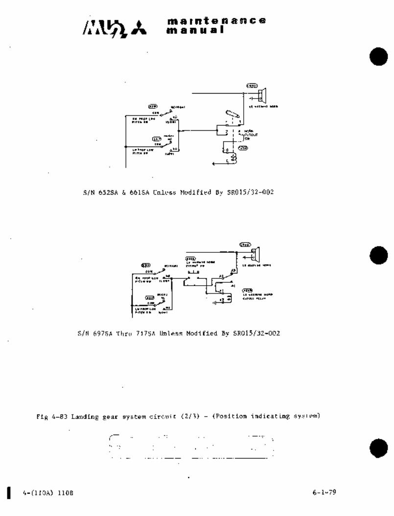
c~Ss It malntelD1WCOmanua9
´•*C(*l.l(l L. 111.11*0 DWM*
cor
idOu taor ror
tlrsn Ir 1LO´•i 1 I 1
?I~ICMIlu,o*, MDJr
(,lld *e I Isw
cou I I
L* r.OP LOI a*01 I,e i´•I~c* Cv I~or,
S/N.652SA 661SA UnlessModified By SR015/32-002
Bllo~
~IOI)IIOI
LO Ill*IW1COllO) rCl*,c*, Cr I ror~a*l*oHoa*
tou _~Y eL~to
Yn ´•rorlorrlrc*.~´• Iror,
rl ~I´•0)
O(IO~I LO Yls*l*O NQ~R
Deli) ?e I rl 5~ CL~OUT .tLIII
COY
L*CIQILOI
´•(~C* I´• ILO1I
S/N 697SA Thru 717SA Unless Modified By SR015/32-002
Fig 4-83 Landing gear system circuit (2/3)- (Positipn indicating system)
4-(1l0A) llOB 6-1-79

CIV42 It malRf8nancemanual
oc cut lo LP 1P1 D00P
(C.IOI) COWIIOL I´•IIIIY
~L18* 0*01 LO SlrCn JY
ILODo~*
or´•a
COIITROL~*tos(0.i)) LO IY´•RWINO HO.W
Ntc*laHI curour i*r .I LIY´•R*I*O .O.H
cou _1´•3*o I ~t
an paol~owrlrcn s~ rrou,-
II T;i33)ri
Io TLIP SI*LG U´•RWIUO HORH
(20´•) REY(YLL IELLI(HlOn)
C~I) *E
couJ I I I
LII dROP LOY bNOIrlrcn ss ILO1I
*I
´•ILE WII)NING HORW
Lt cureur aELlr
c*or UP,
I_ I1OSE LO UPIWD OU
tup;d
(SJZ6)
Iror UP) I
I1H Lb
vp IND SW
(VP)
(5)21)
Ln LlalH LO
W (ND SW h
61CU)IIEI S
(5~28 (UP)
Rn YLG DOOR CLOIE
LIUIT 9Y
OelosL) I elcLosel
Q~ I luasnrrluasnrr
s~ t IJLH YLO DOORCLOSE
POSIYDI ILI.ITS1
(G UN5dFE LI6HT~INOT WVNI
4INOfEI
WOSE L(I 2
.D~** LIYIT ~I´•IDOI*)
ao
Itrot DMII)
(salOnH
RH YIIN LO 11~v -.looww, to
hit
I (NOI WY*)
onzi, j
LH Y~IW LO 2 D
1100*1(1w*r nul~ Ir
as
~L c;i~a,to oo~*
r,owr O,ur,RO nrL1*
Fig 4-83 Landing gear ´•system circuit (3/3) (Position indicating system)
S/N: 718SA thru.73qSA, and S/N’s Modified By SROL5/32-002
------_-,
6-1-79 4-1´•11 (112)
i

on a oat a a a n a a
no a a a a i
12. i’ROUBLE SHOOT~NG L-ANDING GEAR SYSTEM AND BRAKE SYSTEM
Trouble I Probable Cause t Remedy
Main gear forward a. Faulty circuit breaker-"LG Replact-;door does not open in CONT" or "DOOR MOTOR"
gear up operation h. Functional defect of landing gear 1 Replace.control switch.
c. Failure of main gear for~nrd Replace.door actuator.
d. Door open relay does not operateJ Check or replace.e. Open wire or loose terminal of
door open circuit.
f. Functional defect orpoor ndjust- Replace or readjustment of switch in door open ment.
circuit.
g. Main gear forward door hook Check and readjusis not released.
Main gear forward a. Faulty circuit breaker LC I Replace.door opens, but MOTOR.
landing gear is not b. ´•Landing gear up relay does Check or replace.
i retracted not operate.c. Failure of landing gear motor Replace.
Id. Faulty torgue limiter. Replace.e. Open wire or loose terminal Check and repair.
of door open circuit.
f. Functional defect or poor Replace orredd-
adjustment of switch in justment.gear up circuit.
h. Nose geardown lock sticks.. Readjustment or
replace.i. Mechanical atop moving nut Readjustment.
sticks on "DOWN" side.
j. Failure of nose gear actuator. Replace.
Landing gear is a. Door close! relay does not Check or replace.retracted, but main operate.
gear forward door does b. Failure of main gear forward Replace.not close door actuator.
c. Functlonil defect or poor adjust- Replace.ment of up zone switch.
d. Open wire or loose terminal of Check and repair.door close circuit.
e. Functional defect or poor ,7djust- Replace or readjust-ment !if switch in door close ncnt.
Q_: f. Ground doc,r open switch is notcircuit. Set the switch to
set t, "CL~SE" side. "CLOSE" side.
4-113

Im a g at a a a a a aan a a a a I
Trouble Probable Cause I Remedy
.´•~inear ehear pin in maingear Check and replace.forward door mechantem.
h. Functionaldefoct of up zone door Replace or readfufit-safatv limit switch. ment;
blain gear forw;lrd door la. Functional defect dt;~poor ad-i Replace or read;does not open in gear f juatment. t justment.
down operation, b. Dooropen relay does not Replace.operate.
c. Failure of main gear forward Replace.door actuator,
d. Open wire or loose terminal Check and repair.of dbor open circuit.
e. Main gear forward door hook Check and read-
is not released. 1 just.
Main gear forward a, Landing gear down relay does Check or replace,door opens, hut 1 not operate.gear does not Jb, Internal defect of landing Replace,extend gear motor.
c,.0pen wire or looseterminal Check and repair,or geardown circuit.
d, Functional defect or poor .j Replace or adjust,adjustment of gear down
circuit.
a. Mechanical stop moving nut Readjust,sticks on "UPI’ aide.
g. Main gearaft door hook is Check and readjust.
f, Faulty torque limiter, Replace.
not released,
Landing gear extends,(a. Functional defect or poor Replace or read-
but main gear forward adjustment of down eone just.door does not close limit switch.
b. Door close relay does not Replace.operate.
c. Failure of main gear forward Replace,door actuator,
d. Open wire or loose terminal Check and repair.door.close circuit,
e, Ground door open switch i~ Set the to
set to OPEN side, I "CLOSE" si~dc.f. Shear of shear pin in main Check and replace.
ear forward door mechanism.
ESa~e-’ l~a:‘ ~ciicuit POS fND~ Check or’’replace.on in gear up condi- b, Nose gear up indicator switch Check or replace.tion in flight, does not operate,
c, LEI and REI main gear up 1 Check or rep’lace.indicator switches do not
operate.d. LH and RBmain gear forward -jCheck or replace,
door close limit switches
do not operate,a, Faulty unsafe light Check or replece.
4-114

maintenane a.
manual
Trouble Probable Cause Remedy
Unsafe light comes on in a. Faulty circuit breaker "POS IND" Check or replace.gear down condition in b. LH and RH main gear forward door Check or replace.flight. close limit switches do not operate.
c. Nose gear up indicator switch does Check or replace.not operate.
d. LH and RH main gear up indicator Check or replace.switches do not operate.
e. Nose gear down limit switch does Check or replace.not operate.
f. LH and RH main gear down Check’or replace.indicator switches do not operate.
g. Poor engagement of nose gear Check or replace.down lock.
Shear pin is sheared off a. Main gear forward door open limit Check or replace.switch does not operate.
b. Main gear forward door close limit Check or replace.switch does not operate.
c. Door hook is not released when Check or replace.main gear forward door is opened.
Shimmy or vibration in a. Air is mixed in shimmy damper. Bleed air.
taxiing b. Unbalance assembly of nose Readjustment.wheel.
c. Weariness or looseness of torque Readjustment or replace.link pin or shimmy damper
attaching pin.
Abnormal noise in wheel a. Damaged bearing. Check or replace.in taxiing b. Poorlubrication. Relubrication and check.
c. Excessive torque for bearing. Readjustment.
Equal depression on a. Oily lining. Clean lining.brake pedals does not b. Excessive weariness of lining. Replace lining.produce uniform braking. c. Air is mixed in the system. Bleed air.
Insufficient braking d. Operational defect of master Check or replace.effect. cylinder.
e. Blockage in the system. Drain, charge fluid and
clean the system.f. Deterioration of hose. Replace.
g. Insufficient fitting of dise or lining Work brake several times
immediately after replacement. in taxing to get goodfitting.
12-27-99 4-115
c,~l;s’ maintenancemanu a; I
13. CHECK OF ELECTRICAL COMPONENT
13.1 LANDING GEAR UP/DOWN RELAY AND DOOR OPEN/CLOSE RELAY
This check will intend to preclude a significant closed´•failure (fail to open) condition of the relays.
The following equipment is required to conduct this check.
Insulation resistance tester (500 volts r.m.s.)~
DC power supply (O to 50 volts, 1 ampare or above)
Adequate Continuity checker
(1) Preparation
(a) Remove all electrical power from the aircraft.
(bj Disconnect all wires from the terminals of each relay and tag for identification.
(2) Insulation resistance check
(a) Measure insulation resistance between power terminals (Al and A2), and power terminal (Al or A2)
to case (grounded).
(b) Insulation resistance values shall be greater than 50 megohms.
(c) Any relay which does not meet above requirement shall be replaced with a new relay.
(3) Contact operation check
(a) Connect a continuity checker between the power terminals (Al and A2).
(b) Connect a power supply to the coil terminals Xl(pos.) and X2(neg.) and set voltage at 28 volts.
(c) Check for proper continuity discontinuity in the energized and de-energized positions.
(d) Replace the relay with a new relay if this check indicates a failure.
(4) Restoration
(a) Remove the above test equipment and reconnect the wires.
(b) Restore electrical power to the aircraft.
4-116 12-27-99

CHAPTER
FLIGHT CONTROL
SYSTEM

c~slt maintenancemanual
CHAPTER V
FLIGHT CONTROL SYSTEM
CONTENTS
PAGE
1. GENERAL 5-1
1.1 GENERAL DESCRIPTION i 5-1
2. CONTROL COLUMN 5-1
2.1 GENERAL DESCRIPTION 5-1
2.2 REMOVAL AND INSTALLATION 5-2
2.3 RIGGING´•´•´•´•´•´•´•´•´•´•´•´•´•´•´•´•´•´•´•´•´•´•´•´•´•´•´•´•´•´•´•´•´•´•´•´•´•´•´•´•´•´•´•´•´•´•´•´•´•´•´•´•´•´•´•´•´•´•´•´•´•´•´•´•´• 5-2
3. ELEVATOR CONTROL SYSTEM 5-4
3.1 GENERAL DESCRIPTION 5-4
3.2 REMOVAL AND INSTALLATION OF ELEVATOR 5~5
3.3 REMOVAL AND INSTALLATION OF CONTROL CABLE´• 5-6
3.4 REMOVAL AND INSTALLATION OF CABLE SEAL 5-7
3.5 RIGGING´•´•´•´•´•´•´•´•´•´•´•´•´•´•´•´•´•´•´•´•´•´•´•´•´•´•´•´•´•´•´•´•´•´•´•´•´•´•´•´•´•´•´•´•´•´•´•´•´•´•´•´•´•´•´•´•´•´•´•´•´•´•´•´•´• 5-7
4. RUDDER CONTROL SYSTEM 5-10
4.1 GENERAL DESCRIPTION 5-10
4.2 REMOVAL AND INSTALLATION OF RUDDER 5-10
4.3 REMOVAL AND INSTALLATION OF CONTROL CABLE 5-11
4.4 REMOVAL AND INSTALLATION OF CABLE SEAL 5-11
4.5 RIGGING´•´•´•´•´•´•´•´•´•´•´•´•´•´•´•´•´•´•´•´•´•´•´•´•´•´•´•´•´•´•´•´•´•´•´•´•´•´•´•´•´•´•´•´•´•´•´•´•´•´•´•´•´•´•´•´•´•´•´•´•´•´•´•´•´• 5-12
5. SPOILER CONTROL SYSTEM 5-15
5.1 GENERAL DESCRIPTION 5-15
5.2 REMOVAL AND INSTALLATION OF SPOILER´• 5´•16
5.3 REMOVAL AND INSTALLATION OF CONTROL CABLE 5-17
5.4 REMOVAL AND INSTALLATION OF CABLE SEAL 5-17
5.5 RIGGING OF SPOILER SYSTEM 5-18
12-27-99 5-i I

c,~;s’ maintenance1´•\ manual
6. ELEVATOR TRIM TAB CONTROL SYSTEM 5-25
6;1 GENERAL DESCRIPTION 5-25
6.2 REMOVAL AND INSTALLATION OF ELEVATOR TRIM TAB 5-25
6.3 REMOVAL AND INSTALLATION OF CONTROL CABLE 8 CHAIN 5-26
6.4 ELEVATOR TRIM ACTUATOR 5-27
6.5 RIGGING´• 5-29
7. RUDDER TRIM TAB CONTROL SYSTEM 5-32
7.1 GENERAL DESCRIPTION 5-32
7.2 REMOVAL AND INSTALLATION OF RUDDER TRIM TAB 5-32
7.3 REMOVAL AND INSTALLATION OF CONTROL CABLE CHAIN 5-32
7.4 RUDDER TRIM ACTUATOR 5-33
7.5 RIGGING´•´• 5-36
8. AILERON TRIM CONTROL SYSTEM´• 5-37
8.1 GENERAL DESCRIPTION 5-37
8.2 REMOVAL AND INSTALLATION OF AILERON TYPE TRIM 5-38
8.3 REMOVAL AND INSTALLATION OF TRIM AILERON ACTUATOR 5-39
8.4 REMOVAL AND INSTALLATION OF TRIM AILERON BELLCRANK BRACKET 5-39
8.5 RIGGING OF DEFLECTION AND OPERATIONAL CHECK t 5-41
9. FLAP CONTROL SYSTEM 5-44
9.1 GENERAL DESCRIPTION 5-44
9.2 REMOVAL AND INSTALLATION OF FLAP 5-47
9.3 SYSTEM RIGGING AND CHECK 5-53
9.3A SIMPLIFIED FLAP RIGGING PROCEDURES 5-60
9.4 ADJUSTMENT OF FLAP ACTUATING SWITCH 5-60
9.5 OPERATIONAL CHECK OF FLAP SYSTEM 5-64
9.6 MEASUREMENT OF FLAP MOTOR CURRENT´• 5-65
10. WEAR LIMIT AND FREE PLAY ALLOWANCE 5-66
10.1 WEAR LIMIT´• 5-66
10.2 CONTROL SURFACE FREE PLAY 5-67
I 11. CHECK OF ELECTRICAL COMPONENT 5-68
11.1 FLAP UP AND DOWN RELAY 5-68
5-ii 12-27-99

~a a as t e:~ a n c aa ~B a a Bg
1,
1: 1..IENBii,AL~jrh8 cont~:system conblst8 $f;dliai ~ohtrol Yhel?ls ahd rudder pedais for pilot and
an~ $poile~s ak‘;e cohtu’oil~d convehtionall3i by pdsh-puli an~ by~ontrijj. iirheel left aiia liight:
ii~fie ritilder~ iB controlled by thiii rudder pedals located Bbove the floor i f~ont of the
se~ts; ;I’heSe controls are medh8nicailg eonngcted to tdrque tubes, push-pull rdds,
Ij’e;ll~cranks, etc: and cb;nriecte~d ta contfol surfaces dn empennage and wing by ~/32in. .j x 19 cables:fn t~e sijoil~i´• sjrstem, th~ L. i~j and R. I-I. are mpiieci bymeans bf
differential lilrllage located bli wing c;enter
Cabies, except for the spijile~, have turnbuckles n~ar F. STA8490 ai~d 9625 so that
tension adjustment and dlibcdnnectidn can be accomplished through thc~ access door.
Cables should be inspected periodic~iily for cor’rosion, seiratches and brbkenstrahds,
etc.
Elevato~ trim tabs and rudder trim tabs are coi?trolled by rotating the wheels located
on the center pedestal.Both systems are linked to an empennage by 1/16 in. 7 x. 7 cabl~s, which operate
actuators, installed in the hdrizontal stabilizer and the vertical stabilizer, and move
the tabs. Tab motion is shown mechanically on the indicator installed on the center
pedestal.Lateral trim is accomplished by actuating trim ailerons, of unique construction,
which are attached to.the outboard flap trailing edge.Trimailerons arecontrolled by an´•electrical actuator energizedwhen the
control switch is rotated to the.left or to the right;.Trim tab movement
is shown electrically ont2ie indicator.
Double slotted full span flaps consist of inboard and outboard flaps on
both sides of thenacelles. Flapsaremoved as one unit through 9actuators
teach wing half). ’The actuators are driven 6y an electric motor ´•(down:32A 4000 rpm, up: rpmJ.which is operatedby a control switch
in the cockpit, Gears and torque tubes connect the flaps to the actuators.
It is possible to stop the flapsat the UP; 50, 200 and 400 down positionswhich are´•shown by indicator lights located adjacent to the flap control
switch position, Sealedbearings are used in rotating and oscillatingmechanism such as pulleys, bellcranks, quadrants, etc., so´•that routine
inspection and maintenance except special)is minimized.
2. CONTROL COLUMN
2. 1 GENERAL DESCRIPTION
The T~shaped contral,column, located in front of instrument panel, is of welded
construction and moves fore and,aft aroundpivot bearings on,the airframe
attachment section, this motion being transmitted to’the .elevator;control System.A U shaped stop is provided to~´•avo´•id intterferencewith instrument panel, etc., due
toeicessive column travel.
Cbntrol-shdfts attached on both arm ends of the T-column extend through the
instrument panels for control wheel mounting. The control wheel and shaft for the
Gust lockpins´• are provided on both control shafts. Pilot side locapin is
co-pilot can be removed as required.
used tolock control column usually and co-pilot side lockpinis used in
case of removal and installation of instrument panel.
ORIGIM~Lns 5~1
RECEIVED-By ~TP
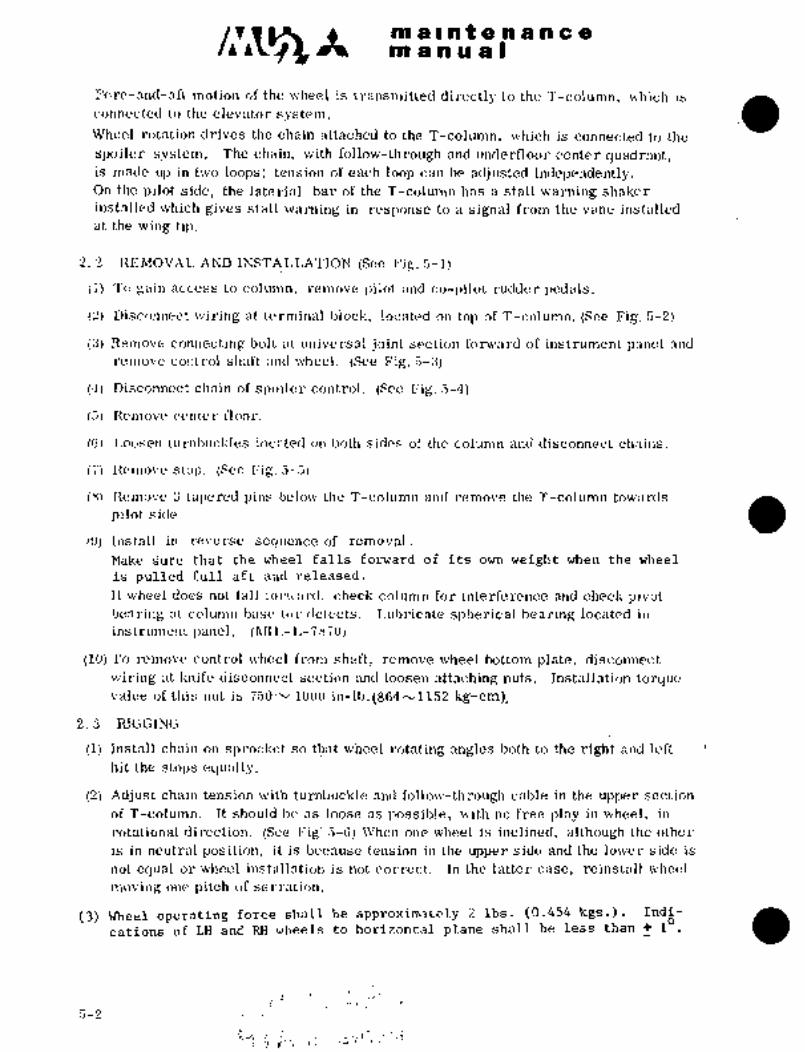
CIt. ma~ntenancem a a a a i
Fore-and-aft motion of the wheel is transmitted directly to the T-column, which is
connected to the elevator system.
Wheel rotation drives the chain attached to the T-colwnn, which is connected to the
spoiler system. The chain, with follow-tl~rough and ´•underfloor ce´•nter cluadrnnt,is made up in two loops: tension of each loop can be adjusted independently,On the pilot side, the laterial bar ´•of the T-cblumn has a stall warning shaker
installed which gives stall warning in response to a signal from the vane installed
at the wing tip.
2. 2 REMOVAL AND INSTALLATION (See J~ig.5-1)
(1) To gain access to column, remove pilol and co-pilot rudder pedals.
(2) Disconnect wiring at terminal block, located on top of T-column. (See Fig’. 5-2)
(3) Remove connecting bolt at universal joint section fonvard of instrument panel and
remove control shaft and wheel.‘(See Fig. 5-3)
(4) Disconnect chain of spoiler control. (See I~ig. 5-4)
(5) Remove center floor.
(6) Loosen turnhuckles located on both sides of the column and disconnect chains.
(7) Remove stop. (See Fig. 5-5)
(8) Remove 3 tapered pins belo\?l the T-column and remove the T-column towards
pilot side.
(9) Install in re-\ierse sequence of removal.
Make ~ure that the wheel falls forward of its own weight when the wheel
is pulled full aftand released.
If wheel does not fall fOl’M’:\I’CI, check column for interference and check pivot
bearing at column base To~.´• tlel’ccts. Lubricate spherical hearing located in
instrument panel. (~RIIIL-I,-7870)
(10) To remove control Mlheel from shaft, re~move wheel bottom plate, disconnect
wiring at linife disconnect section and loosen attaching nuts. Installation torcyuevalue of this nut is 750h´•1Q00 in-lb. (864^´•1152 kg-cm~
2. 3 R;IGGING
(1) Install chnin on sprocliet So that wheel rotating angles both to the righ’t and left
hit the stops eclually.
(2) Adjust chain tension with turnbuckle and follow-through cable in the upper section
of T-column. It should he as loose ´•as possible, with no free play in wheel, in-
rotational direction. (See Fig; 5-6) When one wheel is inclined, although the other
is in neutral position, it is because tension in the upper side and the lower side is
not eclual or wheel installation is not correct. In the latter case, reinstall wheel
moving one pitch of serration.
(3) Wheel operating force shall be approximately 2 Ibs. (0.454kgs.). Indi-
acations of LH and RH wheels to horizontal plane shall be less than 1
C5-2
i. i

B~a a j~ 9.~ 4~P a
PO~i a i~Ba a
_Ii-
B’t11
1. Control wheel 8. Stall warning shaker
2. Control shaft ~9. Stop
3. T-column 10. Elevator push pull rod
4. Gust-lock pin 11. Cen~er quadrant´•
5.~ Sprocket ´•12.´• Spherical bearing ORIGINAL
6. Fdilow through 13. i‘apeS pin As Received ByAT P
7. Terminal block 14. Pivot bearing
Fig. 5-1 Installation of control column
c-~
Disconnect wiring at; terminal~ block Remove cbnnecting bolt at universal:joint
Fig. 5-2 Fig. 5-3
5-3

ran aln~ a a a a a a
m dnual
a
i’
7k-
Disconnect chain of spoiler control ´•Relliove stop
Fig. 5-4 Fig. 5-5
~lt
ORIGINAL
As Received ByAT P
Adj ust follow-through cable
Fig. 5-6
3.. ELEVATOR CONTROL SYSTEM
3. 1 GENERAL DES CRIPTION
The elevator is controlled by pushing forward ~and pulling backward on the control
~heel. Fore-and-aft motion of the T-column rotates the forward quadrant under
t%e floor, by push-pull rods located in the lower end, and moves the 5/32 in.cables
l"unning backward under the floor between keels (second from outboard end, in both
L.H. and R.H. middlesections.). The cables pass through 7 fairleads and pressure
bulkhead seals on the way, then go upward from F. STA 7550, change their lateral
and vertical directions at pulley´•brackets at F. STA 8895 and reach the aft quadrantdn empennage.’ The aft quadrant is connected to the L. H. and R. H. elevator by a
tbrque tube.
~WO down-springs, attached to the horizontal stabilizer front spar, are connected to
the aft quadrant through levers and cables. il’he elevator is normally down with the
aircraft on the ground. The down-spring affords good control feel to pilots and
facilitates longitudinal trim´• at low air speeds.
5-4
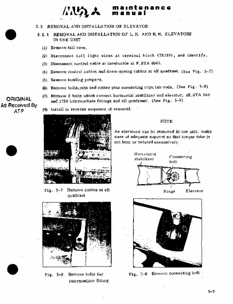
jt ~BiC so a ’4~i) h O$ so (Ciji so os as O
3. 2 Al\jD IINSTA~T;A;rION OF
3. i..i R~MOVAL L. ii; AND R. H. EL~E3ATORS
Ir;r ONE U~IT
(1) Remove tail coi~e.
(2) Disconnect tail light wires at terminal blork (TB319)1 and identify.
(3) Disconnect control cable at turnblckle at F. STA 8605.
(4) Remove dontrol dables and down-spring cables at a~t quadrant. (see Pig. 5-7)
i5) Remove bonding jumpers.
i6) Remove.bolts,nuts and cotter pins connecting trim tab rods. ~(See Pig. 5-8)
(7) I~emove 5 bolts which connect horizontal stabilizer and elevator, (H. STA 840
ORIGINALand 1790 intermediate fittings and aft quadrant). (See Fig. 5-9)
As Received ByAT P (8) Install in reverse sequence of removal.
NOTE
As elevators´• can be removedinone unit, make
sure of adequate support’lso thattorc(ue tube is
not bent ortwisted excessively.
Horizontal
stabilizer Connectingbolt
´•I
Pig, 5-1_ Remove cables at aftHinge Elevator.
quadrant
Fig. 5-9 Remove bolts for Fig. 5-8 Remove connectingbolt
intermediate fitting
5-5

c~´•t ma~nte.ilancein a a a a I
3. 2. 2 REMOVAL AND INSTALLATION OI" L. H. OR R. H. ELEVATOR
(1) Insert rig pin into aft quadrant.
(2)’Remove bolt,nut and cotter pin frbm
elevator trim tab rod,
(3) Remove 6 bolts connecting elevator torquetube to aft quadrant. (See Fig, 5-10)
For installation, tighten nut to
’B)20 to 25 in-lbs (23 to 28.8 kg-cm)torque.
(4) Remove bolt, nut and cotter pin from
intermediate fitting,between H. STA 840
and H. STA 1790 of horizontal stabilizer,
connecting horizontal stabilizer and
elevator.Remove bolts connecting elevator
Remove elevator from aircraft.torque tube to aft quadrant
Fig, 5-10
3. 3 REMOVAL AND INSTALLATION OF CONTROL CABLE (See Fig, 5-11)
(1) Insert rig pin into forward quadrant. (See Fig, 5-12)
(2) Insert rig pin into aft quadrant. (See Fig, 5-13)
(3) Remove turnbuckle from. controlcable at F. STA 8605.
(4) Remove cable terminal fitting from forward and rear quadrant. ORIGINALRemove cable from aircraft. As Received By
(5) Install in reverse sequence of removal. AT P
NOTE
When removing cable, a piece of string tied to
the end of cable and routed in place of cable
which is drawn out will facilitate reinstallation,
Aft quadrant
FU s. STA8605 KTurnbuckle
Cable se~alFus.sTAd025Forward quadrant
Fig, 5-11 nemoval and installation of control cable
5-6

~io a i. a: e il~ i a
8;pa~ a hiW ~ii LB
puadralit Rig pili
Push-irull ro Y
Rig pin
TorqUeAft tube
quadrantPig. 5-12 Fo’rYVard quadrant
Fig. 5-13 Insert rig pin in aft
quadrant
3. 4 REMOVAL AND INSTALLATION OF CABLE SEAL
Cable seal is~ provided at F.STA 4025 to prevent leakage of cabin air pressure
through the hole wherecable is routed. Remove cable seal in accordance with
the´•following procedures.
(1) Remove cabin floor.
(2) Cableseals at F. STA 4025, can´•be removed by removing cotter pins from casingand pulling sealMrward. (See Fig. 5-14)
(3) Install in reverse sequence.of removal.
‘R~ a
ORIGINALEig.~ 5-14 Removal of cable seal
As Received By3.’5 ´•RIGGINC
AT P
3. 5. 1 RIGGING OF CAB-LE
(1) Insert rig pin or gust lock pin into pilot’s control wheel shaft.
(2) Insert´•rig pin into.forivard quadrant.
(3) Adjust length of push-pull rod.
5-7

c;t~ ~1, maintenancem a a u.a I
(4) After confirming that control cable terminal is secured to quadrant, cables are,placed on pulleys properly and guard Fins are installed securely, insert rig pininto aft quadrant.
(5) Miss-matching between elev~tor traililzg edge and tail-cone inner edge and
horizontal stabiliier trailing edge sho~ld he less than 0. 12 in.
(6) Adjust cable tension by turning turnbuckles of F. STA 8605 to the specified value
of 60 Ibs+~ (70´•" Fl.
Compensation of cable tension for temperatures shall be made in accordance
with Fig. 5-62.
(7) After rigging the cable, Install safety wire on turnbuckle and apply alignmentmark to´• lock nut of push-piull rod.
3. 5. 2 ADJUSTMENT OF DEFLECTION ANGLES
Adjustment of deflection angles is accomplished in accordance with the followingprocedures after rigging of cable is completed.
(1) Attach protractor to e~levator at H. STA 855 (See Fig. 5-15).
(2) Remove gust lock pin from controlwheel and rig pins from forward and
aft quadrant´•
(3) Ensure elevator deflection is 280 f 30’ in up direction and 12´°~t 30’ in down
direction when wheel is pulled and pushed.fully.
Tighten lock nut on stop bolt. Apply alignment mark. ORIGINALFor adjustment of angle, adjust rear stop holts.
Install safety wire. (See Fig. 5-16) As Received ByAT P
(4) Detach protractor.
Fig. 5-15 Attaching of protractor Fig. 5-16 Apply alignment mark and
safety wire
3. 5. 3 ADJUSTMENT OF DOWN-SPRING AND MEASUREMENT OF CONTROL FORCE
Adlust dounspnng ul acoordanoo wit the followin~ procedures sfteP Ilgging of acable and adjustment of deflection angle are completed.
(1) Adjust length of cables connecting down-springs and quadrant to 12.40 -t- 12 in~.(315 f 3 mm) (Ref.) by turnbuckle.
5-8

p‘iris a’pn irn a IOan bi~ O- ~n a, an a a c s
:iij iit.t~iicH scal~: to ~onfrol w~bel aria~ meaSure force with
~utopilot servo cdn~rol cables discorii~ected. (See Pig. 5;17)
(~)I.Co$troi wheel. Cdntroi force
Pushed f6rward -20 f 2 Ibs, (-9.0 f 0.9 kg)
Pulled back (*1) 26 ´•f- 2 Ibs.. ’(11.8 t 0.9 kg)(*2) 28 f 2 Tbs, (12.7 0.9
Befo?e Control for~e is measured, place gust lock pin in neutral positionand make pLsh-pU11 scaleiread Q,
1341tll(608f5)
96. 3~7.7
(43.7~t3.5)
Ibs(kg) I I i
slE;wl
o
n 3.46 5.47 :’6
(88) (I39)~´•::g
Stroke
Characteristics of.down springMeasure control force
(b) Control force required for pushing and pulling controlwheel.Fig.5-17
(i) Pull’from.fully down position (contyol surface down position)
25´• 2 Ibs(ll.3f 0. 9 kg)
(ii) Push furtherfrom fullyldown position (cantrol surface Clown position)
-19 f 2 Ibs (-8. 6f 0. kg)
(Measure just before control wheel contacts ~with stop, when control
force is abruptly
(111) Push from´•fully~up position (control surface up position)
-21 f 2 Ibs (-9.5f 0. 9 kg)
(Iv) Pull further from fully up position ´•(control’:surface down position)
28 f 2 Ibs (12. 7 ~t 0. 9 kg)
(MeasUrejust: before control wheel contacts with stop, when control
force is abruptly increased. junit:lbs(kg)
Control
IjPull(upl IPush (down) I ORIGINAL
Control surface 25.~ 2 -19 rtr 2 As Received Byfull down9, (-8. 6~0. 9) AT P
26~ 2 -20‘ ~t 2Neutral´• 11. s~o.s) (-9 -10.9
Control surface:.’´•. 28:~ 2 -21~ 2
full .up (12. 7f0. 9 (-B 5 9
*1 Aircraft.S/N 652SA5-9
n2´• Aircraft S/N 661SA, 697SA- and subsequent

ORIGINAL
c~sA IPi ti Int e n a n c
m a a a a I As Received ByAT P
(3) Re-rig cable connecting down-springwith aft ciuadrant so that measured
control force may be within values
tabulated above.irij
When control force
found abnormal, check the following: t~i
(a) Interference in system.
(b) Adequate cable tension.
(c) Proper tension of down-spring.(See Fig. 5-18)
(d) Control column for binding or Iinte rfe rence.
4. RUDDER CONTROL SYSTEM
Fig. 5-18 Installation of down-spring4. 1 GENERAL DESCRIPTION
The rudder is controlled by pedals which are located on the floor under the
instrument panel. Pedals for pilot and co-pilot are attached independently to
cast brackets installed on the airframe. Pedals can be removed alone or with
lever and attaching shaft as required.When a pedal is pushed, a lever swings, rotating forwa~d quadrant through push-pull rod and cables attached to the quadrant.L. H. and R. H. quadrants are connected together by the forward push-pull rod.
Pedals for pilot and co-pilot move in the same direction and L. H. and R. Il.
pedals move in opposite directions to each other.
A bungee spring is installed in the lower section of the quadrant´•on the pilot’sside to give the pilot good control feel.
By adjusting the length of the push-pull rods within f 0.375 in. (9.5 mm),the fore-and-aft travel of the pedal can be adjusted within 1 in. (25.4 mm).Cables from quadrants run along the pressure bulkhead and at F. STA 1275, turn
aft at right angles, and run between keels. (L. H. and R. H. cables are the
outward cables in the middle section.
Cables pass through 7 fairleads, seals in the pressure bulkhead, and the cable
bracket at F. STtl 7550, and like the elevator system change their vertical and
lateral direction at brackets at F. STA 8895, to reach the aft quadrant in the
empennage
The aft quadrant is attached to the rudder by a torque tube.
4. 2 REMOVAL AND INSTALLATION OF RUDDER
(1) Remove tail cone.
(2) ´•Disconnect tail light wires from terminal block (TB319) dnd identify.
(3) Disconnectcontrol cable from tu´•mbuckle at F. STA 8605.
(4) Remove cables from aft quadrant.(5) Remove bolt connecting trim tab rod.
(6) Remove bonding jumpers (2 places).
5-10
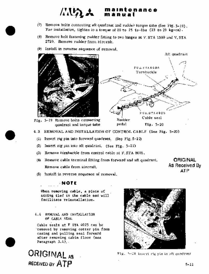
A sn iii i ~n t (P.ii a h 8aaa a a a a I
;(7) ~motre bois cdniiecting Bft quadrant allil rudder torque t~ibe (SeB Fig. 5-i9).For ittstallatibn, tighten to a tbrque df iO to ~5 in-lbs (23 to 29 kg;cm).
(8) Remoire bolt fastening rudder.fitting to t~o hinges at V. $TA i500 and V. STA
2720. Remove riidder from ~irr;raft.
i9j Inii~tBil in FeverSe removal.Aft qu~idrant
FUS.STA8605I
Turnbuckl~
~´•li´•
BNI
E’U S; STA4025
Cable sealFig. 5-19 Remove bolts connecting Rudder
quadrant and torque tube pedal Fig, 5-20
4. 3 REMOVAL AND INSTALLATION OF CONTROL CABLE (See Fig. 5-?0)
(1) Insert rig pin into ´•fonvard quadrant, (Se~e_Fig. 5-2 2)
(2) Insert rig pin into aft quadrant, (See Fig. 5-21)
(3) Remove t;mbuckle from control cable at F. STA 8605.
(4) Remove cable terminal fitting from forward and aft quadrant. ORIGINAL
Remove cable from aircraft.. AS Received ByAT P
(5) Install in reverse sequence of removal.
INOTE
When removing cable, a piece of
string tied to the cable end will "9sll~1facilitate reinstallation.
a´•a
4.4 REMOVAL AND;ISSTALLATION 2!
i~OF:CABLE SEAL
.Cable seals at FSTA 4025can.-be;´•~:n´•
rPmoved by removing cotter pin from
casing and pulling seal -forward-
after removing cabin floor (see ´•r~a
Paragraph 3.4),
s~sllwa/al I’iy. .5-21 \nsdrt ~‘ifi l,iu in ;\ft qu3dr:mt
RECE;VED gy la~BP 5-11

in a ii a a Itn ii ~i ~ilit a .n-a a a a
Forward Rig pin
Rig pin pus~ rod
Forwaril/quadrant
t.´•´• ji
Control cablePedal adjusting rods
Fig. 5-22 Insert rig pin in forward quadrant
4. 5 RIGGING
4. 5. 1 RIGGING OF CABLE
When aircraft is on_the ground, movement of rudder is linked to that of nose gear
steering system. Rigging of cable should be performed after disconnecting the
linkage at steering rod in nose wheel well, or disconnecting nose gear torque link
or jacking aircraft up.
(1) Insert rig pin into pilot´•quadrant.
(2) Adjust length of forward push rod and insert rig pin into co-pilot quadrant.Line up rudder pedals by adjusting length of push rods so that they can be
reached easily.
Ensure that rig pin can be inserted and removed properly.
(3) After confirming that control cable fitting is secured to quadrant, cables are
placed on pulleys properly and guard pins are installed securely,’ insert rigpin into aft quadrant.
(4) Miss-matching of rudder trailing edge and vertical stabilizer. trailing edge(upper) and tail cone trailing edge’ should be within 1/8 in. (3. 2 mm).
(5) Adjust cable tension by turning turnbuckles at´•F.STA 8605 to the specifiedvalue of60 Ibs +5’/-0 (27.2 +2.3/-0 kg) 700F (210C). Compensation of
cable’tensian fortemperature shallbe.made-in accordance with Fig 5-62.
(6) After rigging the cable, install safety wire on turnbuckle. Apply alignmentmark to lock nut of push-pull rod.
If pedal is adjusted, apply alignment mark to lock nut of the adjusting rod.
5-12
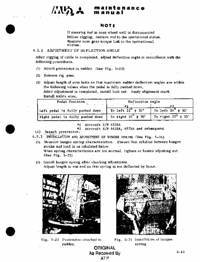
1.´•
~O iQ.´•o.;/L liQ~t i~ ~i ;im I
na.,nnpioaulNblll_lii5du~.ted
biifok´•~ .re~tbre r6ci to ih´•e: dpei’a~iiinai st~itus.
ReStlore riose ~gr torque link to the ap~rationaisi~atus,
4. 5; 2 AajiT;F;’i’ni~E’NT iOiF DEFLEG;r46N
After tig’ging of cable is complete’ci; ~cieflectibri angle in accdrdance iyitii.the
foiloiirli~g
ii) Attacfi to rudder. (Se?e ~ig. 5-23)
(2) Remove rig ~pins;
i. i´•. 1. .1
(3) Adjust rengtn or stop ~olts so ttlat maximum ruaaer aetlectlon angles are wltnln
the follo;jing vallies when the Qedal is fully pushed ilowni
After adjustment is completedi instdll lock n~it; Apply alignment mark.
InStall Bafet~y wire.
Peaal Position Deflection Angle
Left pedai’is fully pusheddown To left 22’ f 30’ To left 24’f 30’
Right Pedal is fully pushed down I To right 240 f 30’ To right 220 f 30’
~1 Aircraft S/N 652SA
*2 Aircraft S/N 661SA, 697SA andsubsequent(4) Detach Protractor,
4.5.3~ ~;INSTALLATION AND ~ADJUSTMENT OF BUNGEE SPRING (See Fig, 5-24)
ci, Measure bungee spring ´•char~cteristics. ;Ensure that relatidn bet;n~een bungeestroke and load is as tabulated below.
When spring characteristics are not normal, tighten or loosen adjusting nut.
(See Fig, 5-25)
(2) install bungee spring aftercheckin~ adjustment.Adjust length at rod end so that spring is not deflected by force.
Fig. 5-23 ~Pl.otrnctol.. ntenched to Fig. 5-24 Instnllfltion of biuigee
rudder; springORIGINAL
As Received By r,-].:3
AT P

m a II at a a a a a ani a a a a)
(27f 2. 3)50
59.41 5
40
33.4~ 2.830
o (15f0.6)ti 20
10
0 0.45 19 1.52(11. 4) (25.4) (38. 6)Stroke in. (mm)
Fig. 5-25 Characteristics of bungee spring
4.5.4 PJIEASUREMENT OF CONTROL FORCE (See Pig. 5-26)
(1) Attach push-pull scale to pedals for pilot. Measure control force for L. I-I. and
R.H. pedals. When L. H. and R. Ii. pedals are moved back and forth from the
neutral position (position where rig pin is inserted) the control forces for both
pedals must be equal.To make control forces for both pedals equal, l~ength of rod end of bungee
spring may be adjusted. Apply alignment mark to rod end.
LBS (KGS)P1 P2
DIRECTION
POSITION PUSH (P1) RETURN (P2) 2
Less than Less than Less than
NEUTRAL 7 (3.2) 7 (3.2) 7 (3.~)
Rudder 30 f 4 -18 4 Less than
deflection *l (13.6 f 1.8) (-8.2 f 1.8) 7 (3.2)
Approximately 240 *2 38 4 ;24 4 Less than
8 (3.6)(17.2 f 1.8) (-10.9 -k 1.8)
N07E
i Control force is usually measured
with the aircraft jacked up and
the nose gear down.
ii Measure control force with auto-
pilot servo control cables dis-
connected.
(2j- If contralf~rce is found unusual, check ~for the following.
(a) Interference in system.
(b) Characteristics of bungee spring.
(c) Brake cylindeyfor distortion, when pedal‘ is depressed´•.
(e) notating parts of each mechanism for lubrication.
(d) Cable foc proper tension.
*1 Aircraft S/N 652SA
*2 AircraftS/N 661SA,697SA and subsequent
5-14

..an r P ii.a ~,.pp ~i( 88 i= aiti a 91 81 D ORIGINAL
As Received ByAT P
P’edai
90"
Nlaster
cylindei-
Fig. 5-26 Measurement of Fig. 5-2j Rigging of pedalforce
4. 5. 5 RIGGING OF PEDAL (See Figi 5-27)
(1) Insert rig pinS into forward quadrants for bo’th pilot and co-pilot.
(2) Adjust the pedal adjusting rods (Fig 5-22) tothe most comfortable
position for the pilot (co-pilot). The adjusting length of the rod
is between 5.82 to6.6-lin. (1480 168 mm) which allows the pedal to
beadjusteda total of 2.0 in. (50.8 ~hm), full-forw8rdto full aft.
(3) Adjust length of´•rod of master cylinder so that pedal may be placed at correct
angle
(4) Rigging of pedal for co-pilot is accomplished in the same way.
(5) Remove rigging pin.
5. SPOILER CONTROL SYSTEM
5. 1 GENERAL DESCRIPTION
The spoilers arecontrolledby rotat´•ing’the control FTheelto the leif´•t and
right in the samemanner as a conventional aileron control. Motion of the
chain on control column is transmitted to cables through the center quad-rant and under the floor. The cables run´•aft between keels, and turn up-
ward at F.STA 8035 along the bulkhead. Then they turn at right angles(through 2 pulley brackets) and reach the differential linkage at the
wing center section. ´•Turnbuckles:’are installed 6869. A~feel
spring in parallel, with the-cable (linearPzing controllforce) is installed
on the bulkhead. Travelra’tio ofdifferential linkage, for spoiler up
and down, is approximately 4:lagainst equal‘input cable travel on LB and
RH sides. Differential linkage consists of: bracket made of cast mag-
nesium, lever, link,etc´•.~,-made of cast~’magnesium or´•aluminum.
From this point, conventional. push-pull rods :are´•used in. the LH and~RH wingsto the bellcranks. The spoiler is divided into inboard’and outboard
sections at W.STA 3800. These sections can’be adjusted independently but
their’ movements are synchroni´•ied.
5-15
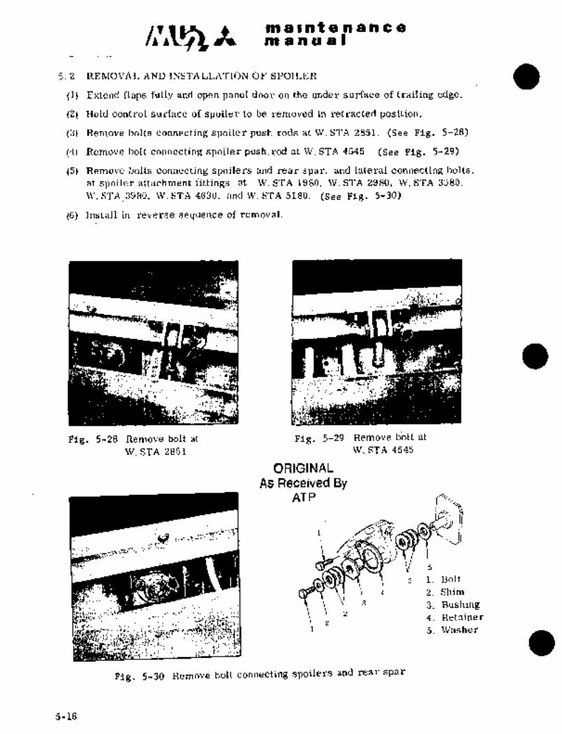
C~1$5 m a i at a a a a a a
an a no a I
5.2 REPUZOVAL AND INSTALLATION OF SPOILER
(1) Extend flaps fully and open panel.door on the under surface of trailing edge.
(21 Hold control surface of spoiler to be removed in retracted position.
(3) Remove bolts connecting spoiler push rods at.W. STA 2851. (See. Fig. 5--28)
(4) Remove bolt connecting spoiler push. rod at W. STA 4545. (See Fig. 5-29)
(5) Remove bolts connecting spoilers and rear spar, and lateral connecting bolts,at spoiler attachment fittings at W. STA 1980, W. STA 2980, W. STA 3580,
W. STA3980, \N. STA 4630, and W. STA 5180. (See F;ig. 5-30)
(6) Install in reverse secluence of removal.
k~-´•
Fig. 5-28 Remove bolt at Fig. 5-29 Remove dolt at
W. STA 2851 W. STA 4545
ORIGINAL
As Received ByAT P
"--~i
z i. Bolt
s 2. Sbim
3 3. Bushingz ’4. Retainer
z1 5. Washer
1 it;f!~:
Fig. 5-30 Remove bolt colinecting spoilers and rearspar
5-16
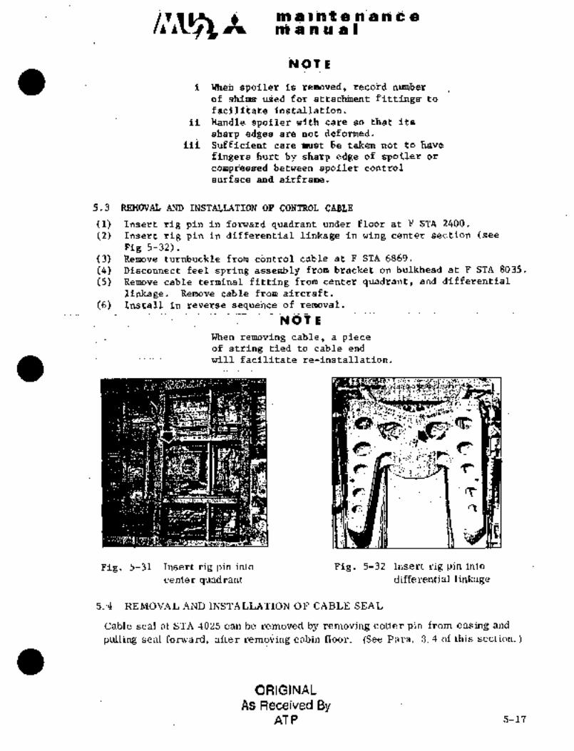
liii ii iii~~C p~i’iC a I
iC~ iii ii
i j6 remoTiedj icec.ok~d niimber
of shitns uSed for fittings to
;ilistalla;tion.
ii handle spoiler with cai~e so tfi~it its
sharp edges aire h6t deformed.
iii care ’nuut be taken not to have
fingers hurt by sharp edge of spoiler dr
compr;e8se~ between spoiler control
surfaCe and airframe.
5.3 REMOVAL AND I~STALLATION dF CO~TROL CABLE
(1) .Tnsert: rig pin in fbrward quadrant under floor at F´•STA 2400.
(2) In~ert ´•rig pin id differeiitial linkage in wing cent~r section (see
Fig 5-32).(3) Remove turnbuckle from control´•cable at F STA 6869.
(4) Disconnect feel .spfingas’sembly from bracket on bulkhead at F STA 8035.
(5) I~emotie cableferminal fitting.from cent’er quadrant, atid differenfial
linkage. Remove cable from aircraft.
(6) sequence of-removal.
NOT E
When removing cable, a- pieceof $tring tied to cable end
will facilitate re-installation.
’I’ Ct´• 1~
tE
Fig. 5-31 Insert rig´•pin into Fig. 5-32 Insert rig pin into
center qljadrant differential linkage
5.~4 REMOVAL AND INSTALLATION OF CABLE- SEAL
Cable seal at STA 4025 ;can be removed by removing cotter pin from casing and
pulling sealforward, after rembving cabin floor. (See Para. 3. 4 of this section.
ORIGINAL
As Received ByAT P 5-17
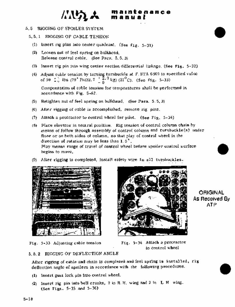
m a a a a Iiiii a cii t a a a a a
5.5 RIGGING OF SPOILER SYSTEM
5. 5. 1 RIGGING OF CAB~E
(1) Insert rig pins into center quadrant. (S~e Fig, 5-31)
(2) ~odsen nut of feel spring on bulld~ead,
Releas~ control cable. (See ~ara. 5. 5. 3)
(3) Insert rig pin into wing center section differential linkage. (See Fig, 5-32)
(4) Adjust cable tension by turning turnbuckle at F. STA 6869 to sl~ecified value
of 50 1:~ Ibs (70" P)(22.72’ 3 kg)(210C). (See Fig. 5-33)
-6
Compensation of cable tension for temperatures shall he performed in
accordance with Fig. 5-62.
(5) Retighten nut of feel spring on bulkhead. (See Para. 5. 5. 3)
(6) After rigging of cable is accomplished, remove rig pins.
(7) Attach a protractor to control wheel for pilot. (See Fig, 5-34)
(8) Place elevator in neutral position. Rig tension of control column chain by
means of follow through assembly of control cblumn and turribuckle(s) under
floor or on both sides of column, so that play of control wheel in the
direction of rotation may be less than 1. 5".
Play means range of travel of control wheel before spoiler control surfacebeginsto move.
(9) After rigging is completed, install safety wire in all turnbuckles.
ORIGINAL
As Received ByAT P
L´•X
Fig, 5-33 Adjusting cable tension Fig, 5-34 Attach a protractor
to contrbl wheel
5, 5. 2 RIGGING OF DEFLECTION ANGLE
After rigging of cable and ~hain is complete’dand feel springis installed, rig
deflection angle of spoilers in accordance with the following procedures.
(1) Insert gust lock pin into control wheel.
(2) Insert rig’pin into bell cranks, 2 in-R. H. wing and 2 in L. Il. wing.
(See Figs, 5-35 and 5-36)
5-18
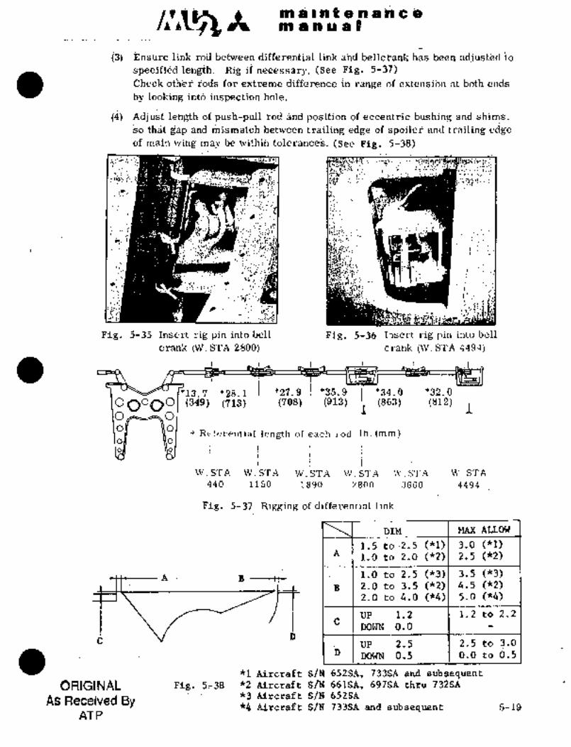
i~ i ~:n a ie~8 asP1 i~jis~ a I
t i.m´•´• -i.;i ´•´•~11-.i:. i.
h jdjiisti~d to(3) r;nsure IlnK roa Denveen alIIerentlal IlnK ana DelrcranK nas rJee
ie’~igth; RigiP (See Fi’g; ´•5-37)
r;ods for xtreliie in i"a´•iige dE:ejitelisii~n gt both i3hd~
iij~ i~oitii;ig ihtd inspe’ctj,ari hole;
;idj i~St leri~t;h of plish-puli gna pds~tibri of ~ccentric ijiisi~ing shilii’s i
~d tji~t gBp arid bet\ireeii edi~$ of gn~ t~i´•giiing eci~em8~n wing ina~jb.e ivit~iih tolerahCes. (See Fig, 5;38)
G:
il.n´•
d-I´•
Pig, 5-35 Insert iig’pin into bell Pig, 5-36 Ihsert rig pin into bell
crank CW. STA 2800) crank (W. STA 4494)
j9*13.7/ *28.1 *27.9 j *35.9 II *34.0 1 *32.0O o (349) (713) (708) (913) B (863) (812) hO O011 ~O
Referential length of each: rod in. (mm)011 ~O
I
W~..STA’ W.STA W. STA‘ W´•. STA’ W. STA W. STA.
440 1150 1890 2800 3660’ 4494
Pig, 5-37 ‘Rigging of differential linl<
DIM MAX ALLOW
1.5 to~2.5 (~kl) 3.0 (kl)A 1.0 to 2.0 (*2) 2;5 (*2)
A- ´•.~´•B 1,0to’2,5 (*3)´• 3.5 (*3)
B 2;0 to 3.5~("2) 4.5 -(*2)2.0 to 4.0 ("4) 5.0 ("4)
UP 1.2 1,2 to 2.2
DOWN 0.0
UP 2.5 2.5 to 3.0
DOWN 0.5 0.0 to‘d.5D
*l:Airc’raft S/N 652SA, 733SA and subsequentORIGINAL Fig.’.:f~-38.’ jiZ.:~rcr8ft S~N 661SA, 69jSA t~Iu 732SA
As Received ByX3 Aircraft S/N 652SG*k--Aircraft S/N. 733SA and subsetluent 5-19
AT P

ni a ii t a ii a a a eli~ a h~u a
(a) Adjustment of push-pull rod. (See Pig. 5-39)Push-pull Lod is adjustable for changing the mismatch between trailingedge df spoiler and that of wing which is given in dimension "D’’ of
Pig. 5-38.
(b) Adjustment of eccentric bushing. (See Pig. 5-40)Remove retai~er. Rotate eccentric bushing clbckwise or counterclockwise.
Change in mis~tch ~etweenleaciing edge of spoiler and that of wing givenin dimension "C", Fig. 5-38, may be changed for vertical adjhstment.
(c) The fwd and af~ horizontal gap adjustment between the spoiler and wingis given in Pig. 5-38, dimensions "A" and "B". This adjustment maybe made by changing the ciuantity of shims between the hinge fittingand the rear spar, refer to Figs. 5-30 and 5-41. All remaining shims
should be installed undeir the bolt head.
NOTE
After link rod and push-pull rod are adjusted,check all rods for range of extension.
_
Tighten lock nut. Apply alignment mark.
I,Y:
Rig pin ‘t~v ~Rig pin
Internal push-pull rod External push-pull rod
(W. STA 4494) (W. STA 2800)
Fig. 5-39 Adjustment of push-pull rod
Shim remained
Retainer
E ccentri c
bushingShim
Eccentric bushing
Fig. 5-40 Adjustment-of Fig. 5-41 Adjustmentof shim
eccentric bushing
(5) Attach a prdtractor to spoiler.’(See Pig. 5-42)Before attaching, remove screws from inboard and:outboard holes.
(6) Remove all rig pins.
5-20

iiQis ~P ~p li~ ;t~a 81aslb a;it e:pl W ieji~
:(7) and ensure defle’ctioii anglebeirig ~i;jithih spij.i~ified rangi~,
Right s’poile~ Left Spoiler
14"~P;5’ Up ;600
Vp 60" i’ Down i4´°tP:5’
Angle betwe~n.l. 8. and H.
spoilers are within l"for both inboard and S-.,jf; _.t~outboard spoilers.Adjustment is mad~ by adjilsting lehgth of
storj bolt in differential linkge. kfterFig. 5-42 attach protractor
adj ustment is completed, tighten lock nutto Spoiler
on stop bolt. Apply alignment mark.
When spoiler deflection does not satisfy the specified values, complete adjustmentin with the following procedures:
(a) When;spoiler angles of both L. ii. .and R. H. are larger or smaller, adjust
stop bolt in differential linkage,
(b) Spoiler deflections of L. H. or R. H.,wing are large or small.
(i) If rotating angles of control wheel to the left and right are~ equal,accomplish re-adjustment´• so that inclinations of bell cranks in both
wings are equal.
iii) If wheel angles for L..H. and R. H1 are not equal, adjust stop bolt for
differential linkage.
(c) When deflections’of inboard and outboard spoilers are not equal, adjustlengths ofpushrodsf~r Inboard and outboard spoilers independently.(When deflection~ is small,:lengthen rod. When it is larg$, shorten it.
Foy this adjustment, mis-alignment:of rigging pin hole position maybe necessary.)
(d) Vl;en deflection is out of’ limit~s’ for any reason, re-adjust differential
linkage in accordance with the following procedures, (See Fig, 5-43)
(i) Confirm that.cable moves i. 93$0.02-O in,(49.0 0. 5
turns 40"~1-o mm~ and quadrant
TO counterclockwise, when wheel iS turned 80f~ (exceptfree play! te:the right.
(ii)’Adjust:length of R.’H; Sod~assembly so that motion of R. Il. bell crank
along X-Y chord is 3. in.(94. 5- _f mm) and adjust length of
stop bolt sothat bell crank makes contact.
(iii) Adjust L.H. side in the.same manner as (ii).:Turn. wheel the direction opposite-to ii).Confin~ that motion’ of R.H. bell c~ank’i´•i; 0. 941 f 0.01 in (23.9f0.2j mm) along X-Z chord.
(iv) of~L: H.~ bell crank´• is-O; 941 f O. 01 in. (23. gfO. 25 mm) when
OBIGINAL A~ R. H. bell,crank is´•turned ´•until it hits the stop,
RECEIVEDBY d88fa r
5-21

ii Int a ;n a a a am ri ii a I
i; ii. XY:3. i2 f ~´•04 in. H.H.
jiz o;94ii,0.bi is, iix (94.5
;0 mm) X
(23, 9 f 0; 25 mrjh~’
It 1´•
UtCable stroke40"+0.02
1.93-0 S"
(49. 0 f 0. 5_O mm)
i. Pulley 4. Arm 7. Bracket
2. Rod assembly 5. Bellcrank
3. Leirer 6. Stopbolt
Fig, 5143 Differentiallinkage
5. 5. 3 REMOVAL, INSTALLATION AND ADJUSTMENT OF FEEL ShRING
(See Fig, 5-44)
(1) Measure characteristics of feel spring.Ensure relationship between stroke and load of spring conforms to figuresgiven in the following table.
If it is found to be abnormal, loosen the nuts in upper cylinder section and
move cap for adjustment. If adjustment in this manner is not successful,
replace spring.
NOTE
Check and confirm spring characteristics before
installation of feel spring.
(2) Since the feel spring is assembled with the cable into a unit, it can only be
removed after disconnecting the cable at the quadrant in the differential
5-22

c~w obo a i~b aa a B
linkage aiid at th8 turh~juckle.Whn installing the assembly to the ser~ation brai=ket, loosen the nuts at bothei~ds ~ufficientiy´• Bo that the s~ring is not deflecte~ initially.
i. 4. f2. 0
(8.BfO.)
11.9 hi;z ORIGINAL(5.4f0.5)
o.As Received By
E4 AT P4.4 f0.5
(2 Ifr 0. 2)
0 0.19 l;g(4.8) (49)
Stroke in.(mm)Characteristics of feel spring
NOT f
After feel spring is mounted on serration bracket,and tension. of control cable is rigged, ensure no
i~nterference between´• inner cylinder of feel spring
tin which.cable is put through) and the cable.
In case ofiriterference, move serrationbracket
to left and right oradjust the bracket backward
and forward.by inserting adjusting shim in order
to avoid interference.
(3) Finger-tighten the adjusting nuts on~both ends of the feel spring.Do nottwist the.terminal in tightening or loosening the adjustingnuts and lock nut.
(4) After installation,tighten and lock the nuts at both ends, hold
tab washers in.position arid apply alignment marks,
MOT~Care must be taken not to over torque the
nuts on both ends.
i. Feel spring body
2. Lock nut 3
B 3. Adj usting cap
5
4. Adjusting nut
5. Tab washer
6. Serration bracket
7. Serration plat~
8. A~d;justlng shjm´•´•´• I~
9. Terminal
Fig.. 5144 Feel spring assembly5-23

/1"111~5 It. -ioi a I ~8(i 8 ii 8 a a a
in a a a a I
5. 4 OF CONTROjL FORCE
(i) Plack push-pull scale on pilot’s control wheel. Measure control farce.
~See Fig. 5-45)values are tabulated’below.
Ibs(kg)
CONTROL FORCE FRICTIONi
DirectiP1 Force increasing
ition PuZjh (P 1 I Return (P 2 P1+ Pt deflection angle.
Neutral 5(2. 3) Max.) 3(1.4) Max. 8(3. 6j Max. Pt Force which
returns control20" position 1 -3fl(-1.4~ 05 8(3. 6) Max.
wheel to
800 position 011 1)-4 rtl(-1.8 0.5)1 8(3. 6) M;LY. neutral position.
NOTL
Measure control´•force
with autopilot servo
control cables dis-
connected.
5. 5. 5 OPERATIONAL CHECK
dl) Check´•‘relation between travel of control
wheel and that of control surface. When
control wheel contacts with stop of
differential linkage, maximum range of
travel of control wheel shall conform to
the value given below.
Fig. 5-45 Push-pull scale placedon control wheel
Rotation of Maximum range Movement of
control wheel of travel control surface
ORIGINAL5´° LH down
Clockwise’(CW) 80´° As Received By3" RH upAT P
Counter-80~
+5~ LH up
clockwise(CCW) 3" RH down
Difference between L. H.~ and R. H. control wheel range of travel should be less
than 5".
(2) Rotate control wheel clockwise and counter-clockwise.
Check fornoise, interference´•and smooth movement of contrdl surface.
When control forces are not normal, check the following.
(a) Interference in system.(b) Chain and cable, tension.
~C) Characteristics of feel spring.
(d) Lubrication.
5-24
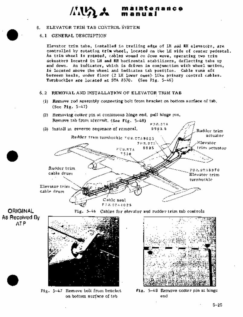
PB~ n ~tl ~in: s
iii ’i’RiiC~ TAB
6; i G~NER4i, ´•DESi=RI~TION
EleTiatcjii trim tabs, inSt8lled iii trailing edgC´•-of LH arid RH ´•eleiratoi~B; are
controi~8d b3i rotating trim wheel-i Idated on the LH side or center p´•edestai.as trini is rotated, ca~les wound on drian rnove, bpbratilig two trim
actuafbr;s locate~d in LH and I~H horizsntsal stabi´•iizers,’defle~ting t~bs
and do~m. ~An indicator, which is driven in cohjunction with wheel motion,PB~ locate~ abdi2e the wizeei and indictes tab position. Cable rims aft
between keels, under floor (TLHlower ones)´•like prima?y control cables.
B~e loc~ted at STA 8370. (See Fig. 5-46)
B. 2 REMOVAL A~D INSTALLATION OF E~EVATOR TRIM TAB
(1) Remove rod assembly connecting bolt from brack~t on bottom su~face of tab.
(See Fig. 5-47)
(2) Removing cotter pin at continuous hinge end, plill hinge pin.
Remove tab from aircraft. ´•(See Fig, 5-48)FUS.STA
(3) Install in reverse sequence of remov&l. 9 9,0 3. 5Rudder trim
Rudder trim turnbuckle Fu s. sTA9625actuator
Fvs.sTn\ /Elevator
PUS.STA 889.5~ actuator
7550
Rudder trimFUS.STA8370
cable drum II --Elevator trim
turnbuckle
Elevator:trim
cable drum
Cable seal
Fus.sTn4025
ORIGINAL Fig, 5-46 Cables for klevator ~gnd rudder trim tab controls
As Received By t’h;P1
AT PC
´•´•,"I;;
r, :dL
i’?´•
l.Z ;pl;:A’
apIt
iB ~iiq I!Pi7kSi? :~ie
’9’"..S,~r:
Fig, 5-47 Remove bolt from‘bracket Fig, ~5-48 Remove cotter pin at hinge
on bottom surface of tab end
5-25

m$rntehancem anus)
8. 3 ~tEMOVAL AND INSTALLA~ION dF CONTROL CAB~E AND CHAIN
(1) Insert gust lock pin into control wheel.
(2) Insert.rip pin into cirum of elevator trim forward of center pedestal in the
cockpit. (See Fig, 5-49)
(3) Insert rig pin into elevator trim actuators (both L. H. and R. H. )(See Fig, 5-50),
(4) Disconnect cable from turnbuckle at F. STA 8370.
(5) Remove rig pin from drum.
(C;I dr´•um, r´•t´•rnc,ve cable terminal without impairing cable on drum of
elevator triin. Remove forward cable from aircraft.
(7) Remove rig pin from trim actuator. Open access panel on bottom surface of
inboard horizontal stabilizer. Remove pin from chain.
Remove aft cable from aircraft. (See Fig. 5-51)
(8) Remove tail cone. Remove trim actuator chain cover. Install chain.
(9) Install in reverse secluehce of removal. Note the following when installingchain.
(a) Adjust length of turnbuckle of chain to 6 f 0. 04 in.. (152. /Ifl mm).
(b) Ensure no interference of pin on cable terminal with chain sprocket and
pulley of trim actuator when trim is moved to maximum extent.
NOTE
i If drum is rotated inadvertently in removingcontrol cable, cable may be entangled or com-
pressed between guide pins and impaired.
´•ii When removing cable, a piece of string tiedto
cable end’will facilitate re-installation.
j
´•:,d I:
Fig. 5-49 Inserf rigpin Fig, 5-50. Insert rig pin into
into drum trim actuator
ORIGINAL
As Received By5-26
AT P

c~rmaintenancemanual
Detail of joint of cable and chain
6~0. 04 in.(152.4~1 mm)
´•i’-’’bfi~!"
Fig. 5-51 Disconnect cable Fig. 5-52 Adjustment of turnbuckle
and chain
6.4 ELEVATOR TRIM ACTUATORORIGINAL
6.4.1 REMOVAL AND INSTALLATIONAs Received By
(1) Insert gust lock pin into control wheel.AT P
(2) Insert rig pin into drum of elevator trim in center pedestal.
(3) Remove bolt connecting trim tab to rod assembly of actuator.
(4) Remove 2 bolts attaching trim actuator from the gap between horizontal
stabilizer and elevator.
(5) Open access panel of trim actuator. Remove 2 bolts attaching actuator.
(6) Remove chain guide. Remove chain from sprocket.Remove trim actuator from aircraft. (See Fig. 5-53)Pin may be removed from connecting part of cable and chain to facilitate
removal of chain.
(7) Install in reverse sequence of removal.
Precautions for installation of trim actuator are shown below.
(a). Before installation, place trim actuator and rod assembly in neutral
position and ensure dimension as indicated in Fig. 5-54.
(b) Tighten bolt connecting rod assembly with tab finger tight. Insert cotter
pin securely.
NOTE
Al alloy washer iNAS 1197-10) should be placedunder attaching bolt head when installing,
5-27
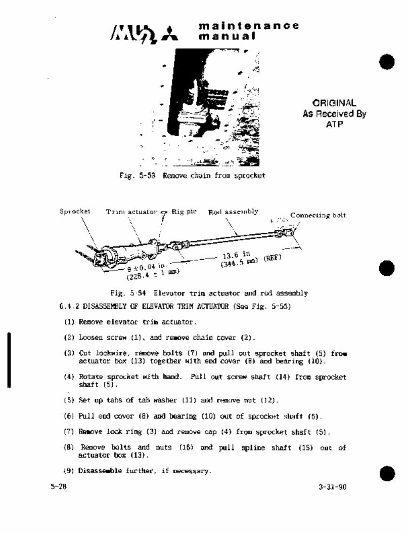
maintenancemanual
I
B~e
´•%"-:i,
ORIGINAL
As Received By
ti-
AT PI,
´•ct~-
Fig. 5-53 Remove chain from sprocket
Sprocket Trim actuator
PRig pin Rod assembly
Connecting bolt
13.6 in
sso. 04 ’""".5 mm~ (REF)
(228.4
Fig. 5-54 Elevator trim actuator and rod assembly
6.4.2 DISASSEMBLY OF ELEVATOR TRIM A@I~UATOR (See Fig. 5-55)
(1) Remove elevator trim actuator.
(2) Loosen screw (1), and remove chain cover (2).
(3) Cut lockwire, r~move bolts (7) and pull out sprocket shaft (5) fromactuator box (13) together with end cover (8) and bearing (10).
(4) Rotate sprocket with hand. Pull out screw shaft (14) from sprocketshaft (5).
(5) Set up tabs of tab washer (11) and remove nut (12).
(6) Pull end cover (8) and bearing (10) out of sprocket shaft (5).
(7) Remove lock ring (3) and remove cap (4) from sprocket shaft (5).
(8) Remove bolts and nuts (16) and pull spline shaft (15) out ofactuator box (13).
(9) Disassemble further, if necessary.
5-28 3-31-90

maintenancemanual
6.4.3 INSPECTION AND LUBRICATION OF ELEVATOR TRIM ACI~UATOR
(1) Wash all metallic parts with dry cleaning solvent (P-D-680) and dry.
(2) Visually check all parts for abnormal wear, damage, crack or
corrosion and replace if necessary.
(3) Apply grease (MIL-G-23827) on the following points during reassembly.
a. Ball and needles of bearing (10)
b. Thread and spline of screw shaft (14)
c. Internal surface of spline shaft (15), especially internal splineand internal surface of bushing (17)
6.4.4 REASSEMBLY OF ELEVATOR TRIM ACTUATOR
(1) Reassemble in reverse sequence of disassembly.
(2) Make sure that the actuator actuates smoothly for full stroke after
reassembly.
(3) Adjust the length of rod end (19) so that distance between outer
side of sprocket and center of rod end hole may be 9 0.04 in
(228.4 1 mm) when actuator is set to neutral position and rig pinis inserted, and tighten lock nut (18). (See Fig.5-54)
(4) Install elevator trim actuator on the airplane.
6.5 RIGGING
6.5.1 RIGGING OF CABLE TENSION
(1) Insert rig pin into elevator aft quardrant. (See Fig.5-13)
(2) Insert rig pins into L.H. and R.H. trim actuators.
(3) Insert rig pin, into cable drum in center pedestal.
(4) Rotating turnbuckle at F.STA 8370, adjust cable tension to the
specified value of 10f~ Ibs (70"F) kg) (21"C).Compensation of cable tension for temperatures shall be performed in
accordance with Fig 5-62.
(5) After rigging is completed, install safety wire on turnbi~ckle.
(6) Remove rigging pins.
NOTE
After rig pins are removed, chain must not be looserthan it has been before rigging.
3-31-90 5-29

ma~ntenancemanual
i. Screwand nut 2. Chain cover 3. Lockrln~
4. Cap 5. Sprocket shaft G..Oil seal
7. Bolt 8. End cover 9. Packing
10. Bearing 11. Tab washer 12.´• Sut
13. Actuator box 14. Screw shaft 15. Spline shaft
16. Bolt and nut 17. Bush
88: 5
18. Lock nut 19. Rod end
8
3 10
11
12
h___
613
a
1416
1~ 19
1~18
Fig.5-55 Elevator trim actuator
5-30

maintenancemanual
6.5.2 RIGGING OF DEFLECTION
After cable rigging is accomplished, rig tab deflection in accordance
with the following procedures.(1) Insert rig pin into elevator aft quadrant.(2) Insert rig pin into trim actuator.
(3) Adjust length of rods so that mis-match of trim tab trailing edgesand elevator trailing edges is less than +0.04 in. (+1 mm).
NOTE
(i) Check to see if a threaded portion of clevis is visible
through the inspection hole in the operating rod.
(ii) If threads are not visible, loosen the other end of the
operating rod and adjust both ends so that threaded
portions are visible through inspection holes, and
alignment is achieved at trailing edge.
(4) Attach protractor to trim tab at H.STA 400. Set pointer to "O".
(5) Remove rig pin from trim actuator.
(6) Operate elevator trim wheel and check the relation between the
indication and deflection.
Trim wheel Indication Tab deflection
(fl)Not"UP" Turn to "NOSE UP" direction 30" 2" DOWN 300 a’ modified
Reach to stop after 4 4/5 turns by S/B
NEUTRAL 0" 0" 1" 079/27-010("2)
"DOWN" Turn to "NOSE DOWN" direction Modified
STOP will be reached after 110" 2" UP 10" by S/B1 3/5 turns (*1) (fl) 079/27-
STOP will be reached after 1" (f2) 1" ’~Tf2) 010
1/6 turn ("2)
(7) Remove rig pin from elevator aft quadrant.(8) Tab should not move more than +2" (or 0.20 in. (5.1 mm) at tab
inboard trailing edge) at 330 up and 10" down positions of
elevator when control wheel is fully pulled or pushed with the
condition of trim indicator setting to the neutral position "O"
Adjustment is made by adjusting the length of actuator [9 ~0.04 in.
(228.6+1 mm) ref.] or by adjusting location of actuator.
(9) After rigging is completed, tighten lock nut on rod assembly, and
apply alignment mark.
6.5.3 RIGGING OF TRIM WHEEL
Trim wheel control force is 1.3 to 2.2 Ibs (0.6 to 1.0 kg).If the control force is beyond this limit, rerig trim wheel in
accordance with the following procedures. (See Fig.5-56)(1) Remove cap from center of trim wheel.
(2) Remove screw from nut holding wheel.
(3) Loosen or retorque nut holding wheel so that trim wheel may be
(4) Tighten screw on nut to hold wheel in position. Reinstall cap.
rotated with specified control force.
5-2-94 5-31
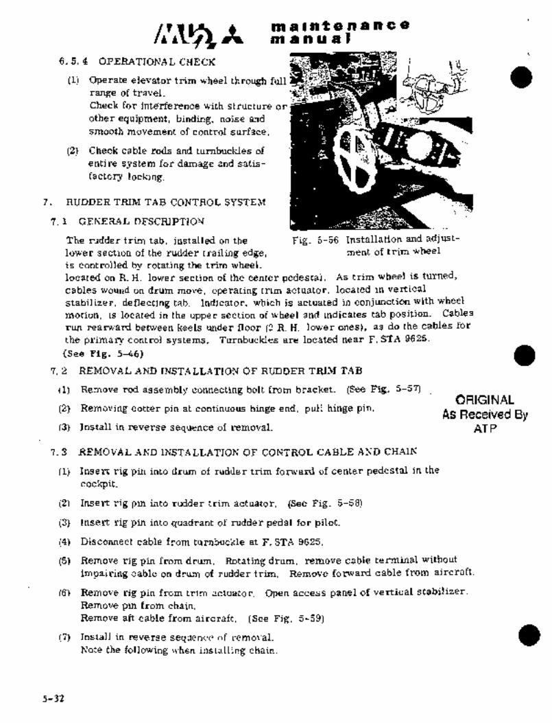
C~3A ma~ntenancemanual
6. 5. 4 OPERATIONAL CHECK
(1) Operate elevator trim wheel through full
range of travel.
Check for inte~rference with structure or
other equipment, binding, noise and
smooth movement of control surface.
(2) Check cable rods and turnbuckles of
entire system for damage and satis-
factory locking.
7. RUDDER TRIM TAB CONTROL SYSTEM
7. 1 GENERAL DESCRIPTION
The rudder trim tab, installed on the Fig. 5-56 Installation and adjust-
lower section of the rudder trailing edge, ment of trim wheel
is controlled by rotating the trim wheel,located on R. H. lower section of the center pedestal. As trim wheel is turned,
cables wound on drum move, operating trim actuator, located in vertical
stabilizer, deflecting tab. Indicator, which is actuated in conjunction with wheel
motion, is located in the upper section of wheel and indicates tab position. Cables
run rearward between keels under floor (2 R. H. lower ones), as do the cables for
the primary control systems. TurnbucMes are located near F. STA 9625.
(See Fig. 5-46)
7. 2 REMOVAL AND INSTALLATION OF RUDDER TRIM TAB
(1) Remove rod assembly connecting bolt from bracket. (See Fig. 5-57)ORIGINAL
(2) Removing cotter pin at continuous hinge end, pull hinge pin.As Received By
(3) Install in reverse sequence of removal. AT P
7. 3 REMOVAL AND INSTALLATION OF CONTROL CABLE AND CHAIN’
(1) Insert rig pin into drum of rudder trim forward of center pedestal in the
cockpit.
(2) Insert rig pin into rudder trim actuator. (See Fig. 5-58)
(3) Insert rig pin into quadrant of rudder pedal for pilot.
(4) Disconnect cable from turnbuckle at F. STA 9625.
(5) Remove rig pin from drum. Rotating drum, remove cable terminal without
impairing cable on drum of rudder trim. Remove forward cable from aircraft.
(6) Remove rig pin from trim actuator. Open access panel of vertical stabilizer.
Remove pin from chain.
Remove aft cable from aircraft. (See Fig. 5-59)
(7) Install in reverse sequence r,f removal.
Note the following when installing chain.
5-32

ORIGINAL
As Received By maintenanceAT P manual
(a) Install chain so that both ends may meet at neutral position when rig pin is
inserted in actuator.
(b) Ensure no interference. ´•of pin on cable terminal with chain sprocket and pulleyof trim adtuator´•when Itrikn. is moved to maximum extent.
Fig. 5-57 Remove connecting Fig. 5-58 Insert rig pin into
bolt from bracket trim actuator
NOT L:
i´• If drum is rotated inadvertently when
removing control cable, cable may be
entangled or compressed between guardpin and impaired.
ii. When removing cable, a piece of
string tied to cable end willfacilitate re-installation.
Fig. 5-59 Remove connecting7.4 RUDDER TRIM ACTUATOR pin and cable
7.4.1 REMOVAZ~ AND INSTALLATION OF RUDDER TRIM ACTUATOR
(1) Insert rig pin into quadrant of rudder pedal, pilot side (see Fig 5-22).
(2) Insert rig pin into drum of rudder trim in center pedestal.(3) Disconnect cable from turnbuckle at F STA 9625.
(4) Remove chain guide. Remove chain from sprocket. Pin may be removed
from connecting part of cable and chain to facilitate removal of chain.
(5) Remove 4 bolts attaching trim actuator. Remove trim actuator from
aircraft.
(6) Install in reverse sequence of removal. Precautions for installation
of trim actuator are shown below.
(a) Before installation, place trim actuator and rod assembly in
neutral position and ensure dimension as indicated in Fig 5-60.
(b) Tighten bolt connecting rod assembly with tab finger tight.Insert cotter pin securely.
5-33

c~s Itmaintenanceman u.al
NOTE
Al alloy washer (NAS1197) should be placed under
attaching bolt head when installing.
Actuator Rod assembly Connecting bolt
Rig pin
zo.o i"’
~sos0.04 in.
14.622(371´•4~ Ima)
Fig.5-60 Rudder trim actuator and rod assembly
7.4.2 DISASSEMBLY OF RUDDER TRIM ACTUATOR (See Fig.5-61)
(1) Remove rudder trim actuator.
(2) Loosen screw (1), remove chain cover (2).
(3) Cut lockwire, remove´•bolts (7) and pull out sprocket shaft (5) from
actuator box (13) together with end cover (8) and bearing (10).
(4) Rotate sprocket with hand. Pull out screw shaft (14) from sprocketshaft (5).
(5) Set up tabs of tab washer (11) and remove nut (12).
(6) Pull end cover (8) and bearing (10) out of sprocket shaft (5).
(7) Remove lock ring (3) and remove cap (4) from sprocket shaft (5).
(8) Remove bolts and nuts (16) and pull spline shaft (15) out of
actuator box (13).
(9) Disassemble further, if necessary.
7.4.3 INSPECTION AND LUBRICATION OF RUDDER TRIM AC~UATOR
(1) Wash all metalic parts with dry cleaning solvent (P-D-680) and dry.
1 (2) Check all parts for abnormal wear, damage, crack or corrosion
visually and replace if necessary.
(3) Apply grease (MIL-G-23827) on the following points duringreassembly
a. Balls and needles of bearing (10)b. Thread and spline screw shaft (14)c. Internal surface of spline shaft (15), especially internal
spline and internal surface of bushing (17)5-34 3-31-90

ma~ntenancem an a a I
´•1. Screwandnu~ 2. Chain cover 3. Lock ring
4, Cap 5. Sprocket shaft 6. Oil seal
7. Bolt s. End cover 9. !’a~king
10. Bearing II. Tab washer 12. Nut
13. Actuator box ;4. Screw shaft 15. Spline shaft
Bolt and nut I’I. Ij:lshin~
li3. Lock nut 19. F:ijd end
1-
ks
io
P11
;j 12
i; i i3
14 --Iti
15 19
17
Is
FiF~5-61 Rudder trim actuator
5-35

C~SZ- Itmaintenancemanual
7.4.4 REASSEMBLY OF RUDDER TRIM ACTUATOR
(1) Reassemble in reverse sequence of disassembly.
(2) Make sure that the actuator actuates smoothly for full stroke after
reassembly.
(3) Adjust the length of rod end (19) so that distance between outer
side of sprocket and center of rod end hole may be 14.622 rt 0.04 in.
(371.4 1 mm) when actuator is set to neutral position and rig pinis inserted, and tighten lock nut (18). (See Fig. 5-61)Ensure that the bolt hole in the rod end (19), swivel bearing, when
centered, is parallel with the rig pin.
(4) Install rudder trim actuator on the airplane.
7.5 RIGGING
7.5.1 RIGGING OF CABLE
(1) Insert rig pin into trim actuator.
(2) Insert rig pin into cable drum in center pedestal.
(3) Remove access panel forward of tail cone. Insert rig pin into
rudder aft quardrant.
(4) Rotating turnbuckle at F.STA 9625 adjust cable tension to specified_,
Ibs (70"F) (4.5f~.3 kg) (21" C)value of 10+5Compensationof cable tension for temperatures shall be performed inaccordance with Fig.5-62.After rigging is accomplished, install safety wire on turnbuckle.
100
802+Sj/ I ~I Elevator Rudder
soSpoiler
50
40 Elevator trim actuator
Rudder trim actuator
201 //r I I i /1/16"1*710
+5Tolerance Ibs
-o-11 o 20 40 60 70 80 100 120F
c j +2.3-O kg)Atmospheric temperature´•
Fig.5-62 Temperature compensation table for cable tension
5-36 3-31-90
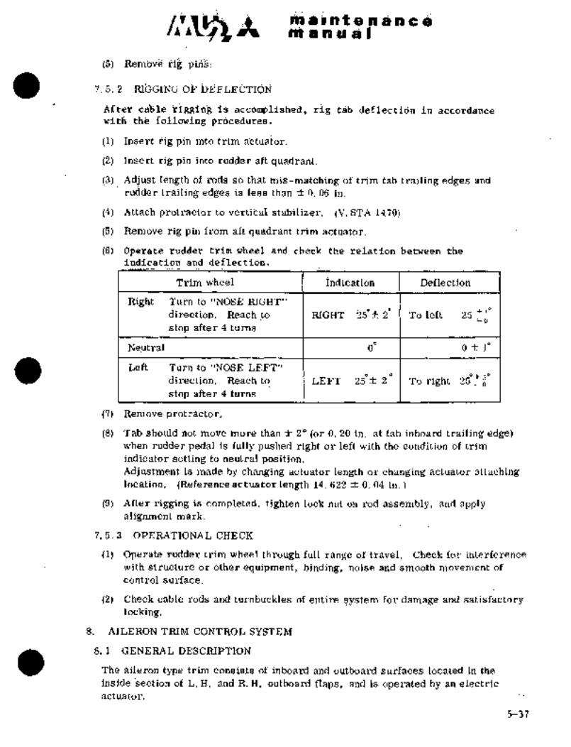
li~iii ~i C i~i t PO si ccIP1 a a ai B
-:´•´•.´•.,.i(5) Rem~ve rig
7. 5. i RI%%I~G i3i~ ij~DEFLE?i´•l ´•.:1_
Afte3 caijle is rig t~b in
witii fh~ prdceddres.
(i) Insert ~ig pin ihto trim a~ctuator.
(2) Insert i;ig pin into rudde~ aft quadrant.
(3) Adjust length of rods so that mis-matd’hing of trim tab trailihg i~dges and
ru;lder tr.ilirig edges is less than f 0. 06 in.
(4) Attach protractor to vertibal stabilizeri (V. STA 1470)
(5) Remove rig pin from aft quadrant trim actuator.
(6) Op~Late rudd~r triin wheel and check the relation between the
indication and -deflectio~.
Trim. wheel i~ndication Deflection
Rili~ht Turn to "NOSE RIGHT"
direction. Reach to RIGHT 2Sf 2 To left 25t"´°
-o
stop after 4 turris
Neutral 0 Ofl"
Left Turn to "NOSE LEFT"
direction. Reach to’´• LEFT 2 To right 25-C 30-O
stop after 4 turns
(7) Remove p’rot racto r.
(8) Tab should not move more than f 2"´•(or 0. 20 in. at tab inboard trailing edge)when rudder pedal is fully pushed right~ or-left with the condition of trim
indicator setting to neutral position.Adjustment is made by changing actuator length orchanging actuator attachinglocation. (Reference actuator length 14. 622 f 0. 04 in.
(9) After rigging is completed, tighten lock nut on rod assembly, and applyalignment mark,
7. 5. 3 OPERATIONALi=HE i=K1.
(1) Operate ruddertrim wheel t6ro~ghfull range of travel. Check for interference
with structure or other equipment, binding, nbise ´•and smooth movement of
control surface.
(2) Check cable rods and turn6uckles of entire system for damage and satisfactorylocking.
8. AILERON TRIM CONTRO.L SYSTEM
8. 1 GENERAL DESCRIPTION
The aileron type ´•trim consists of inboard and outboard surfaces Icicated´• in the
inside section of L. H. and R. H. outboard flaps, and~is operated by an electric
actuator.
5-37

m a I ~f a a a a
IIB a a a a I
Actuators, bell push rods, etc., are located in flaps and are electrically
pedestal is held iii the left or right position, the actuators in the flaps are enei´•giz-
connected with wings. If the contrbl switch located in the center of t~he center´•
ed to move the control shrfaces. The momentarily ON switch sprihgs back to its
origii~al neutral position, wi~eh it is released, stopping actuators at bnce. If the
sttiitch is held in the operating positidn, the actuators are stopped at the maximum
deflected position automatically by a built-in limit switch. Actuator motion is
picked up by potentiometers and shouin on an indicator located above the control
switch. Inboard and outboard aileron trim tabs connected by linkage are moved
in the same direction. The L. H. and R. Il. klectrically connected aileron typetrim tabs move in opposite directions to each other.
Although operating speeds of the L. H. and R. H. actuators are usually different,
accumulation of differences is avoided because the actuator is stopped
momentarily by means of neutral limit switch.
When the aileron trim selector switch, located on the switch panel, is selected in
the right or left position, interconnection between L. H. and R. Ii. tabs is dis-
connected and the control surface which has been selected can be operated
independently. Therefore, flight safety is assured even if the control surface on
one side is in-operative.
8. 2 REMOVAL AND INSTALLATION OF AILERON TYPE TRIM
(1) Remove bolts connecting inboard and outboard push rods.
(2) Remove hinge pin holder of trim aileron, draw the pin out and remove trim
aileron from aircraft. (See Fig. 5-63)
(3) Install in reverse sequence of removal.
Zp
A *~-(L-
ORIGINAL
As Received ByAT P
Fig. 5-63 Remove connecting bolt;
and hinge l,in holder
5-38
C~A li~iw $I li8li ~t iri 99 99 e isi~8d ;ah~ ho u i
8.3 AND INSTALiATION C~F TRIM AILERON A~;TUATOR (See Pig 5-64)
II) Place trin Hileroh in neutral posifion.
(2) actuator access panel,
Disconnect wiring to act~tor and switches and identify.
(4) Remove colter pin, nut,-washer and bolt connecting the bellcrank
with the rbd end of the actuator.
(5) Remove cotter pin, nut, washer and bolt attaching actuator.
(6) Remove actuator from the aircraft.
(7) Installin reverse seijuence of removal, noting the following.
(a) Before installing, adjuststroke "L" (Fig 5-64) of trim actuator
to 8.62 +0.04/id.00 in. (219 +1/-0 rmn) at retracted position. The
rigging is made by means of the actuator rod end andEXT and RET
screws of the trim actuator limit switch. After rigging, install
safetywire on the screws.
(b) Install actuator andconnect bellcrank.
NOt L
Place actuator in RET positionto fdcilitate installation.
(c) Tighten attaching hardware to proper torque, install cotter
pin and apply alignment mark.
(d) Remove wire identification and connect wiring.
(e) Perform operational check in accordance with Para 8.5.
8.4 BWDVAL PIID INSTALLATIO~ OP TRM AILERON BI~LCaANK BRA~ET (See Pig 5-64)
(1) Place trim’aileron in neutral position.
(2) Remove actuator access panel.
(3) Disconnect wiring to actuator and switches and identify.
(4)’ Remove push-pull rod from bracket on outboard trim aileron Control
surface.
(5) Remove cotter p~n, nut washer ´•and bolt.connecting the bellcr9nk
with the rod endof the actuator.
(6) Remove 2 bolts attaching..neutral switch to bracket and remove switch.
(7) Remove 4bolts atta~hing bellcrank bracket assembly to the aircraft
and remove bracket. .assenhbij´•~::
(8 install in reverse sequence of remolal;´• after torquing attachinghardware, apply alignment mark. Remove wire ident~ification and
connect wiring. Perform operationalcheck in accordance with Para 8.5.

.ai~ a-a at in a a a aPBP a h ii a I
2 f p
"-1io
i;~"´•’’c
t
’CI’Aircraft S/N 652SA, 661SA, 697SA tkru-713SA and 715SA
1 7 2 3 i,
11 I
’1
D
L
io
2~ 001
B
Aircraft S/N 714SA, 716SA and subsequent
,1. Wire 7. Actuator
2. Potentiometer arm 8. Limit switch
3. Bracket 9. Bellcrank
4. Neutral limit switch 10. Push rod
5, Push-pull rod 11. Poisiton Indicator
.Potentiometer6. Attaching bolt
Pig. 5-64 Installation of trim aileron actuator
5-40

ni ri a i’i~ t a a i ai he eihl a ii~C;i~ a III
8.5 RIGGING OF AM) OPEI~TIONAL CHECK
MQTE
Do trim actuator
continuou$ll´• for checkingafteiinstall~tion.
Stop’for~3 to5 minutes a´•ft~r
2 consecutive operation.
8.5.1 LOCATING NEUTRALPOSITION
(1) Insert rig pin’into inboard and outboard bellcranlis.
(2) ~ittach protractor to control surface at upper portion of´• push rod
(see Fig’ 5-65.(3) Adjust the lengths of outboard and inboard push rods so that mismatching
of trim tab trailing edgeand flap trailing edge is less than 0.04 in.
(1 mm): at trim tab o~tboard edge. (For mismatching of inboard edgeand flap actuator.box,see P,Eter.:-´•rfgging; ’tighten lock
nut on the rod. Check through inspectionhole for proper lengthof rod screwed in.
(4) Rembve rig pin.
8.5.2 RIGGING OF DEFLECTION
(1) Operate trim aileron as follows:
Close circuit breakers ~RIM AIL and TRLM POS.
Place control switch:~´•in LOWER LN WING or LOWER´•RH’ WING po~ition.(2) Adjust limit switches located in the actuators so that: deflection is
direction. After rigging, installsafety wire.
~3) Adjust neutral‘´•limit- switch of trim aileron ´•so that switch may operatesatisfactorily at neutral position (dflo) (see Fig5-66). Loosen
switch lock nut so that plunger of neutral limit swit~ch may be ON
atOo of deflection. After rigging, install safety wire. Confirm
that plunger of switch is not bottoming and has suffi~ient marginof stroke atON position.
Fig. 5-65’ Attach protractortocontrol´• surface
a i"--
OF$QGgNAL 1´•~´•
R"EI"ED BY ;5-41

m a a a atm a I ri t a a a a a a
8.5,3 ADJUSTMENT OF POTEN~IOMETER
(1); Remove actuator acce’ss panel to gain access to the trim aileronindicator potentlometer.
NOTE
It may be necessary to remove the
potentiometer-bellcrank assemblyfrom the aircraft.
(2) Insert a rig pin through the bellcrank for neutral positionand connect a multitester to terminals per below. Loosen lever
arm set screw and turn potentiometer shaft to indicate 5 f 0.5 K
ohms resistance. Tighten lever arm se~ screw against potentiometershaft.
LH potentiometer Pins B (2) and CCW (1)
RH potentiometer Pins B (2) and CW (3)
(3) Remove rig pin and install potentiometer-bellcrank assembly in
position, tighten attaching bolts and nuts to proper troquevalue and apply alignment mark.
(4) Connect electrical wires.
(5) Close circuit breakers TRIM AIL and TRIM AIL POS. Adjust resistor
at the back of center pedestal, so~that trim aileron’indicator may read
O-wfth control surface held in neutral position. Afterthe adjustment,
lock resistor knob securely. (See Fig. 5-68)
5-42

m´•inierahnsOo~ iti iig iui ~a I1I
I
S.
i:t:´• ii"~
Fig. 5-66 Adjustment of neutral Fig. 5~-67 Adjustment of
’limit switch potentiometer
8.5.4 OPERATION OF TRIM AILERON
(1) Close circuit breakers TRIM AIL
and TRIM PdS. Place´• selector
switch in BOTH position;re
(2) Place trim aileron control switchon
center pedestal in LOWER LH WING or
LOWER RH WING~ position, and the
control surface will move as follows:
ORIGINALFig. 5-68 Adjustment of "O" position
As Received ByAT P
Position Movement of control surface Swing of
Control switch LH RH Indicator
LOWER L WING Vp Down Left
LOWER R WING Down Up Right
If trim aileron is operated in opposite direction, check wiring and correct.
(3) Place selector switch in LH EMERG or RH EMERG positions.
(41. Place trim aileron control switch in LOWER LH WING or LOWER RH WING
positions, and thec~ntrol surface will move as follows:
Movement ofSelector switch Control’ switch
control surface
LH EMERG LOWER LH WING LH alone up
LOWER RH WING. LH alone down
nH EMERG LOWER LH WING RH fllone´•down
LOWI~R RH WING R1-l ;Ilone
5-43
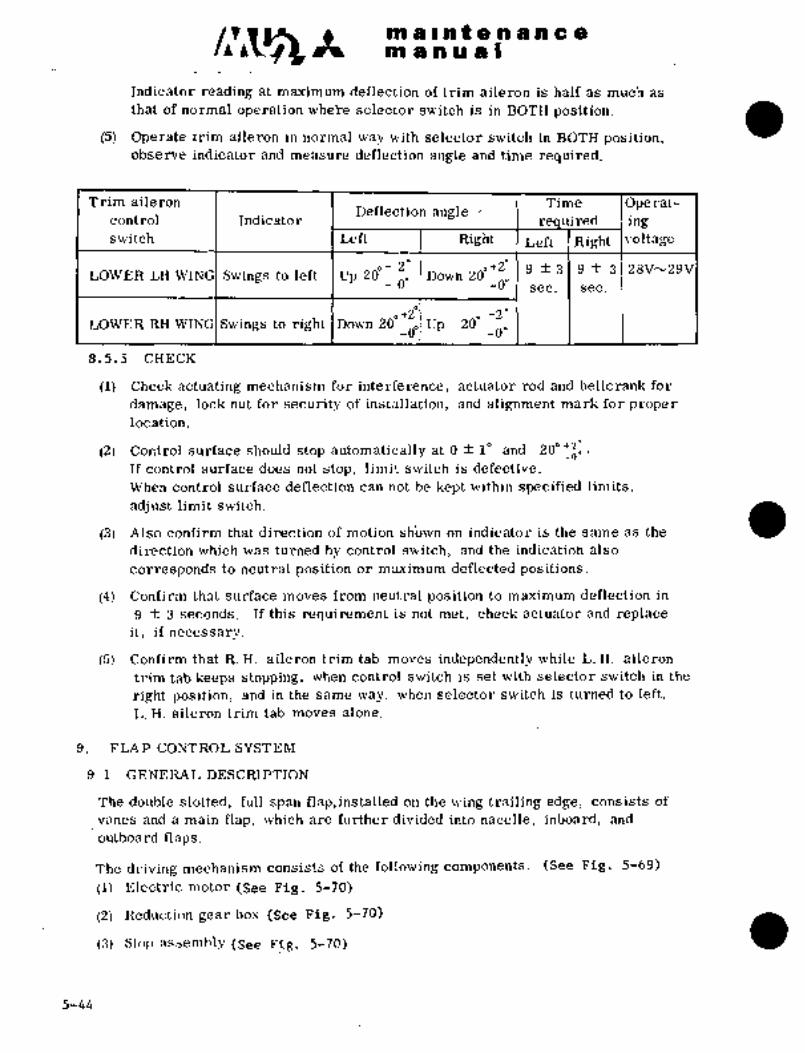
mallnfenancemanuiP1
Indicator reading at maximum deflection of trim aileron is half as much as
(5) Operate trim aileron in normal way with selector switch in BOTH position,
that of normal operation wheire selector switch is in BOT~ positidn.
observe indicator and measure deflection angle and time required.
Trim aileron Time Ope rat-Deflection angle
control Indicator uired ingswitch ´•Left Right Left Right voltage
of 20 ,+2" 9 f 3 9 f 3 28V~29VLOWER LH WIN Swings to left Up 20 Down 20
-0’ -0" sec. sec.
+2´° +2"LOWER RH WINGISwings to right IDown 200 Up 200
-0"
8.5.5 CHECK
(1) Check actuating mechanism for interference, actuator rod and be’llcrank for
damage, lock nut for security of installation, and alignment mark for proper
location.
(2) Control surface should stop automatically at O f 10 and 20"+~%.If control surface does not stop, limit switch.is defective.
When control surface deflection can not be kept within specified limits,
adj ust limit switch.
(3) Also confirm that direction of motion sh’own on indicator is the same Bs the
direction which was turned by control switch, and the indication also
corresponds to neutral position or maximum deflected positions.
(4) Confirm that surface moves from neutral position to maximum deflection in
9 f 3 seconds. If this requirement is not met, check actuator and replace
it, if necessary.
(5) Confirm that R. H. aileron trim tab moves independently while L. H. aileron
trim tab keeps stopping, when control switch is set with selector switch in the
right position, and in the same way, when selector switch is turned to left,
L. H. aileron trim tab moves alone.
9. FLAP CONTROL SYSTEM
9. 1 GENERL\L DESCRIPTION
The double slotted, full span flap,installed on the wing trailing edge, consists of
vanes and a main flap, which´•’are further divided into nacelle, inboard, and
outboard naps.
The driving mechanism consists of the following components. (See Fig. 5-69)
(1) Electric motor (See Fig. 5-70)
(2) Reduction gear box (See Fig. 5-70)
(.7) Stop Rssemhl~y (see Fig. 5-´•70)
5-44

C1~5k BPi a i~ ii t e a a a a aBB1 1 PI a a i
(4) Maih actuator (See Fi$..5-71)
(5) Inboard.auxiiiajry actu~ator (See Fig. 5-72)
(6) Outboard auxiliary actuator (See Fig. 5-73)
(7) Guide mechanism (See Fig; 5-74~)
(8) Torque tube assembly
(9) Flexible shaft assembly
Each actuator consists of: a bevel gear box, jack screw, jack nut, guide rail,
rollers and links and transforming torque tube rotation to flap deflection.
Flap moves backward along-guide rail and then turns with its center of rotation at
a rear end guide rail when the flap touches it, resulting in a specific deflection.
Limit switch is energized and stops the flap at´•the same time.
:Flap deflection is determined by main actuators, and auxiliary actuators onlycorrect fore-and-aft mis-alignment offlaps.The jack screw in the L’. ii, wing.is -aL. H. threaded screw and 1*n the n. H. wing
is a R. H. threaded screw.
The stop assembly’ protects the system, ov~rdoming stall torque of motor´•, when
limit switch is inoperati´•ve. Control switch in cockpit has 3 or 4 positions, i.e.,
UP, 50 20q.´•’and 40f When switch is placed in any one of them, the flap stops
automatically in the selected position, and the indicator lamp illuminates.
Between 10 and 200, the control surface is moved intermittently.
In normal operation, flap does not stop at intermediate positions.
When greasing huts of inboard auriliar31 actuator and main actuator, inject grease
(MIL-G-21164) until the grease overflows from top of nuts or threads.
i. Flapmotor2. Reduction gear box
6 8 4 7 9 7 5 1 3. Stop assembly.4. Main actuator
5. Inboard auxiliaryactuator
6. Outboard-auxiliaryactuator
7. Universal joint8, Flexible ~shaft assembly9. Bearing stand
1 3 7 5´• 7 -´•9: 7
/i ~ns nih i
Fig. 5-69 .:Flap driving mechanism
5-~5
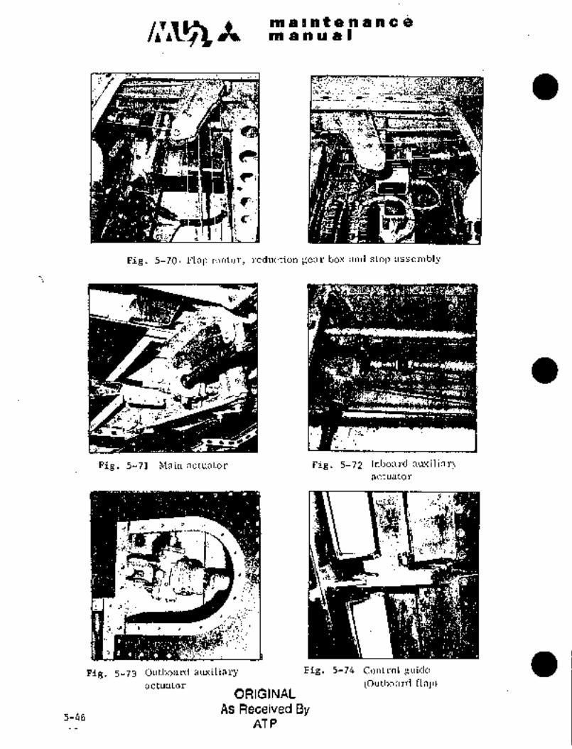
c~sarir a a nt’e rs’Ple a
tiia ’a ~aol a all
;.i;; :´•P 3:;ia´•; :4
~:p´•’-
-1 1 I t
Fig. 5-70 Flap motor, reduction gear box and stop assembly
H’
´•c;~
eL 3´•-~iwy_,
so
Fig. 5-71 Main actuator Fig. 5-72 Inboard Buxiliar3iactuator
:´•i´•li~0rs:
c´•
jTT"
8 1 1
Fig. 5-73 Outljoard aiuriliary Fig. 5-74 Control guide
actuator (Outboarul flap)ORIGINAL
As Received By5-46
AT P

i
A BDO a OP a Bta as B ~O g ´•n b an C a
a. 2 Fi-IAP
anil ’df fisjp is a~d;bmpiished ~d- accord~since witli the f~oliijwiiigbn tlie followili~ pa~eg.
(2) Di’son~ct dehtrii ma~i actuator jad& froin ~psear box. (8ee i~ai´•a. 8. 2. 2)
(3) Discd;iinect gctuato;i. ja~k sci~eiir frdm gear 6ox. (SEse Pai~a. 9. 2. 3)
bttljoard gctciator jack sdrei~ iroiri roller asaembiy fittin~.(See pgjr., 9. i.crj
(5) Remove guide iillk niechanism from outer flap. (See Pa~a. 9. 2. 5)
(6) ´•Discdnnect trini aileron wi~ing routedfrom outer flap to wing.
~See Para. 9. 2. 6)
(7) Disconnect iriboard ´•flap and outboard flap from central main actuator box
assembly. (S’ee Para; 9,2; 7)
Af~er above´• pro.cesses are completed, remove inner flap, outer flap and central
main actuator box assembly from aircraft.
´•Install.in reverse sequence of removal.
9. 2. 1 REMOVAL AND INSTAiLATION OF -NACELLE FAIRING
(2) Remove 5 screws on the upper´•side of nacellefairing trailing edge.
(1) Place the flap in the extended position.
(3) Remove 5 screws on the upper and inner ´•side of nacelle fairin~.
I(See Fig. 5-75)
(4j Remo~ie:access panel. Remove 4 bolts fastening nacelle fairing and flap.
(See´•Ffg. 5-76)
(5) Remove nacelle fairing’from aircraft.
(6) Install inreverse sequence of removal.
a
c.g;:;F
´•t cls.:
PiR. 5-75 Rem~ve screws from Fig. 5-76 Remove bolts fasteningnacelle fairing nacelle fairing and flul~
ORIGINAL
As Received By ~-47
AT P

a r a t ie a a a a 4
9. 2. 2 REMOVAL AND INSTALLATION OF CENTRAL MAIN ACTUATOR
JACK SCREW (See Fig, 5-77)
Removal should be done as follows:
(1) Place flap at 200 down position.
(2) Remove cap from jack support.
(3) Disengage jack screw from serration of gear box with flap held by hand.
(4) Take jack screw accompanied by bearing out of nut support by rotating byhand.
NOTE
Do not allow flap to be lowered, when removing
jack screw from nut support.
Installation should be done as follows.
(1) Place jack nut on gimbal.
(2) Screw in jack screw from back of jack support.
(3) Screw in jack screw until serration at the tip of jack screw reaches gear box.
(4) Connect jack screw to gearbox with flap held at 200 down pqsition. After
inserting jack screw into gearbox serrated hole, turn jack screw to make
sure of smooth operation. If jack screw does not move smoothly, loosen
gearbox attaching screws once with jack screw connected to gearbox,
and then retighten the screws. Make sure that gearbox does not interfere
with wing rear spar web. If It interferes, elongate the gearbox attach-
ing hole 0.OS in. (2 mm).
00
1 2 3 4 5 ii i 9 I’o
1. Gear box 6. Jack su’pport
2. Jack nut block 7. Bearing
3. Gimbal 8. Nut
4. Jack nut 9. Cap
5. Screwjack 10. Actuator box
Fig. 5-77 Insl:~ll:itlon OT main actuutu~’ sc~c_w j:~ck
(5) To hold jack screw in position, tighten nut in jack support, install cotter pinand place cap in position.
5-48

lia a ii a a I
9. 2. 3 REMOVAL ~ANIj irjSi‘ALLATIC)N OF INBOARD AC’I’UATDR JACK sdn~w
(see i-78)
Eieknoval shoul;l be done with flap in iOO down positibn as ~oliows:
~1) kemov~ bolt and nlit attaching jack screw: Disconnect jack screiv from gear
boi´•.
(2) Rotate jack screw by liandl and remove from jack nut.
Installation:
(1) Scre~i jack sck´•eiv irito jack nut.
(2) Plac;e jack~screw into geai´• box. Hold it in position with bolt and nut.
In;C~tBil ~otterpin.
1 2 3 1 4 8
i. Gear box 4. Plate
2. Scre’w jack attaching bolt -5. Screwjack
3. Jack nut 6. Guide rail
Fi~..5-78 Installation of inbo8rd actuator s’crew jack
9. 2. 4 .REMOVAL´•AND .INSTALLATION- OF OUTBOARD A CTUATOR JACK SCR~W
(See Fig.. 5-79)
Removal:
(1) Place flap’in 200 down position. Remove bolt and nut fastening tip of jackScrew and gimbal.
Installation
(1) Extend wing. by screwing to allow installation of flap,
(2) Connect tip of jack screw‘from gimbal: Hold it in position with bolt and nut.
Install cotter pin.
5-49
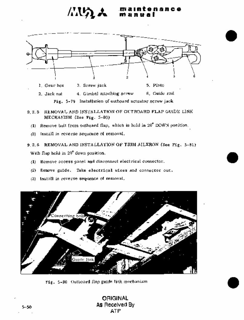
.Ilbi a i n% a I$ a Ple~aba a a a 81
4 5 a
1. Gear box 3. Screwjack 5. Plate
2. Jack hut 4. Gimbal attaching screw 6. Guide rail
Fig. 5-79 Installation of outboard actuator screw jack
9. 2. 5 REMO;VAL AND INSTALLATION OF OUTBOARD FLAP GUIDE: LINK
MECH~ANISM (See Fig. 5-80)
(1) Remove bolt from outboard flap, which is held in 200 DOWN position.
(2) Install in reverse sequence of removal.
9. 2. 6 REMOVAL AND INSTALLATION OF TRIM AILERON (See Fig. 5-81)
With flap held in 20" down position.
(1) Remove access panel and disconnect electrical connector.
(2) Remove guide. Take electrical wires and connector out.
(3) Install in reverse sequence of removal.
C onnect
i´•iQ
1 -~CcaP D’~
i: i;´•--
Guide link
Fig, 5-80 Outboard flap guide link mechanism
ORIGINAL
5-50As Received By
AT P

Bai~ a a lie a B
1. Guide
2. Electric wire
Pig. 5-81 Installation of trim aileron electricwire
9. 2. 7 REMOVAL AND INS1~ALLATION OF INBOARD AND OUT.BOARD FLAPS
Removal should be done after jack screw link mechanism and electrical wiringare removed,~ as follows:
(1) Place flap in 20" down Position.
(2) ´•Remove.bolt and outb6ard flaps ih.central´• main actuator
bori au’serribly. :(See Fig. 5’82)
(3) Remove roller assembly at endof flap from guide rail with inboard
Slap held. Remove inboard flap from aircraft.
(4) Remove roller assembly at outer end´• of flap from guide r/ailwith outbo~ard
flap held. Remove ´•sutboard flap from aircraft.
Installation should be done as follows.
(I) :Set flap actuator box as configured for 20" down‘on guide rail of central main
actuator. (’See Fig. 5-8?)
(2) Set roller assembly at inner end of inboard flap on guide rail of inboard
actuator- at W. STA 664.
(3) Set roller assembly at outer end of outboard flap on guide ´•rail of-outboard
actuator ´•at W. STA 4755.
Fig. 5-82 Remove flapconnecting Fig. 5-83 14ctuator- box on
bolt from. actuator-box guide rail
QFdi B G I NAL As 5-51
RECEIVED BY

an a I! at a a in a a aan a a a a I
(4) Install inboard and outboard flaps and actuator box as a unit into a space
Tentatively attach inboard and outboard flaps to actuator box with bolts.
where flap is retracted.
(See Fig. 5-84)
Guide rail
Roller
Fig. 5-85 Position of roller
Fig. 5-84 Attach tentatively inboard
and outboard flaps to
actuator box ORIGINAL
Bolis need no~ be tightened to re.ular Lomue. AS Received By aAT P
Use 25/32 in, wrench.
(5) Place assembled inboard and outboard flaps in.200 down position and adjust
as follows:
Att aching Inboard Actuator
(a) Inboard and outboard actuatorbolt flap box assy.
rollers should contact the surface
of guide rails, when roller of
flap actuator box contacts the
rotating surface of jack support.
(b) Rollers of inboard and outboard
actuators should be placed at the
center of guide rail. (See Fig. 5-85) Bushing IThe abovementioned adjustments I yl 1\1 Washer
Eccentricare possible by increasing or
decreasing number of washers orbushing 111 (1~ \Hollow
boltby relocating eccentric bushing;
(See Fig. 5-86)
(6) With flap retracted, adjust gap and
mismatch between flap and acti~atorFig. 5-86 Adjustment of
roller positionbox, and between flap and wing to
the specified limit. (See Fig. 5-87)
5-52
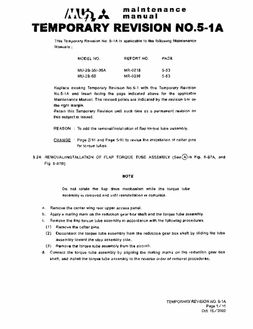
maintenancemanual
TEMPORARY REVISION N0.5-~AThis Temporary Revision No. 5-1A is applicable to the following Maintenance
Manuals
MODEL NO. REPORT NO. PAGE
MU-2B-351-36A MR-0218 5-53
MU-2B-60 MR-0336 5-53
Replace existing Temporary Revision No.5-1 with this Temporary Revision
No.5-1A and insert facing the page indicated above for the applicable
Maintenance Manual. The revised points are indicated by the revision bar on
the right margin.
Retain this Temporary Revision until such time as a permanent revision on
this subject is issued.
REASON To add the removallinstallation of flap torque tube assembly.
CHANGE Page 2/11 and Page 5/11 to revise the installation of cotter pins
for torque tubes.
9.2A REMOVALIINSTALLATION OF FLAP TORQUE TUBEASSEMBLY (See~in Fig. 5-87A, and
Pig. 5-878)
NOTE
Do not rotate the flap drive mechanism while the torque tube
assembly is removed and until reinstallation is complete.
a. Remove the center wing rear upper access panel.
b. Apply a mating mark on the reduction gear box shaft and the torque tube assembly.
c. Remove the flap torque tube assembly in accordance with the following procedures.
(1) Remove the cotter pins.
(2) Disconnect the torque tube assembly from the reduction gear box shaft by sliding the.tube
assembly toward the stop assembly side.
(3) Remove the torque tube assembly from the aircraft.
d. Connect the torque tube assembly by aligning the mating marks on the reduction gear box
shaft, and install the torque tube assembly in the reverse order of removal procedures.
TEMPORARY REVISION NO. 5-1A
Page 1/11Oct. 15/2002
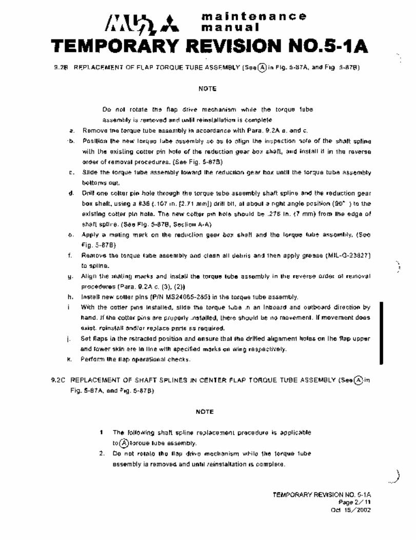
maintenancean a a u a I
TEM’PORARY REVISION N0.5-llA9.2B REPLACEMENT OF FLAP TOR~UE TUBE ASSEMBLY (SeeO in Fig. 5-87A, and Fig. 5-878)
NOTE
Do not rotate the flap drive mechanism while the torque tube
assembly is removed and until reinstallation is complete.
a. Remove the torque tube assembly in accordance with Para. 9.2A a. and c.
´•b. Position the new torque tube assembly so as to align the inspection hole of the shaft spline
with the existing cotter pin hole of the reduction gear box shaft, and install it in the reverse
order of removal procedures. (See Fig. 5-878)
c. Slide the torque tube assembly toward the reduction gear box until the torque tube assembly
bottoms out.
d. Drill one cotter pin hole through the torque tube assembly shaft spline and the reduction gear
box shaft, using a #36 (.107 in. 12.71 mml) drill bit, at about a right angle position (90" )to the
existing cotter pin hole. The new cotter pin hole should be .276 in. (7 mm) from the edge of
shaft spline. (See Fig. 5-878, Section A-A)
e. Apply a mating mark on the reduction gear box shaft and the torque tube assembly. (See
Pig. 5-878)
f. Remove the torque tube assembly and clean all debris and then apply grease (MIL-G-23827)
to spline. f\~g. Align the mating marks and install the torque tube assembly, in the reverse order of removal
procedures.(Para. 9.2A c. (3), (2))
h. Install new cotter pins (PIN MS24665-285) in the torque tube assembly.
i. With the cotter pins installed, slide the torque tube in an inboard and outboard direction by
hand. If the cotter pins are properly installed, there should be no movement. If movement does
exist, reinstall and/or replace parts as required.
j. Set flaps in the retracted position and ensure that the drilled alignment holes on the flap upper
and lower skin are in line with specified marks on wing respectively.
k. Perform the flap operational checks.
9.2C REPLACEMENT OF SHAFT SPLINES IN CENTER FLAP TORQUE TUBE ASSEMBLY (See~inPig. 5-87A, and Pig. 5-878)
NOTE
1. The following shaft spline replacement procedure is applicabl~
toO loTqUe tube assembly.
2. Do not rotate the flap drive mechanism while the torque tube
assembly is removed and until reinstallation is complete.
TEMPORARY REVISION NO. 5-1A
Page 2/11Oct. 15/2002

maintenanceman ual
TEMPOWARY REVISION N0.5-~Aa. Remove the torque tube assembly in accordance with Para. 9.2A a. and c.
b. Replacement of the shaft spline connected to the stop assembly shaft.
(1) Remove the torque tube assembly bolts, washers, nuts and cotter pins.
(2) Remove the existing shaft spline from the stop assembly side of the torque tube assembly.
(3) insert the new shaft spline into the stop assembly side of the torque tube assembly.
(4) Connect torque tube assembly by aligning the cotter pin holes of the reduction gear box
shaft and the torque tube assembly, and install the torque tube assembly temporarily in the
reverse order of removal procedures. (Para. 9.2A c. (3), (2))
(5) Install the cotter pin in the torque tube assembly temporarily.
(6) Set the shaft spline protrusion to the specified dimension (L2) and retain the shaft spline
inseition position using masking tape or other suitable materials. (See Pig. 5-870)
(7) Remove the torque tube assembly in accordance with Para. 9.2A c. (1), (2) and (3).
(8) Drill two #3 (.213 in. [5.41 mml) drill bit holes in the shaft spline to match the existing tube
ass(3mbly holes and ream .2213’.000’5 ,,d clean all debris.
(9) Install the shaft spline with new bolts ~NAS3003-12D), washers (AN960-10L) and´• nuts
(AN320-3), and secure the nuts with new cotter pins (MS24665-132).
c. Replacement of the shaft spline connected to the reduction gear box shaft.
(1) Remove the torque tu´•be assembly bolts, washers, nuts and cotter pins.
(2) Remove the existing shaft spline from the reduction gear box side of the torque tube
assembly.
(3) Insert the new shaft spline into the reduction gear box side of the torque tube assembly.
(4) Connect the torque tube assembly by aligning the inspection hole of the shaft spline with
the existing cotter pin hole of the reduction gear box shaft, and install the torque tube
assembly temporarily in the reverse order of removal procedures. (Para. 9.2A c. (3), (2))
(5) Install the cotter pin in the torque tube assembly temporarily.
(6) Set the shaft spline protrusion to the specified dimension (L1) and retain the shaft spline
insertion position using masking tape or other suitable materials. (See Pig. 5-87D)
(7) Remove the torque tube assembly in accordance with Para. 9.2A c. (1), (2) and (3).
(8) Drill two #1 .(.272 in. [6.91 mml) drill bit holes in the shaft spline to match the existing tube
assembly holes and ream .2813+.000’5 ,,d clean all debris.
(9) Install the shaft spline with new bolts (NAS3004-14D), washers (AN960-416) and nuts
(AN320-4), and -secure the nuts with new cotter pins (MS24665-134).
d. After completion of shaft spline replacement, install the torque tube assembly in accordance
with Para. 9.28, b through j.
TEMPORARY REVlSlON NO. 5-1A
Page 3/11Oct. 15/2002
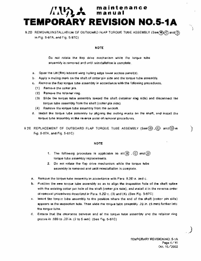
C~31-tmaintenancemanwal
TEMPORARY REVISIOM N0.5-~A9.2D REMOVALIINSTALLATION OF OUTBOARD FLAP TORQUE TUBE ASSEMBLY (See~O and~
in Pig. 5-87A, and Pig. 5-87C)
NOTE
Do not rotate the flap drive mechanism while the torque tube
assembly is removed and until reinstallation is complete.
a. Open the LH (RH) inboard wing trailing edge lower access panel(s).
b. Apply a mating mark on the shaft of cotter pin side and the torque tube assembly.
c. Remove the flap torque tube assembly in accordance with the following procedures.
(1) Remove the cotter pin.
(2) Remove the retainer ring.
(3) Slide the torque tube assembly toward the shaft (retainer ring side) and disconnect the
torque tube assembly from the shaft (cotter pin side).
(4) Remove the torque tube assembly from the aircraft.
d. Install the torque tube assembly by aligning the mating marks on the shaft, and install the
torque tube assembly in the reverse order of removal procedures.
9.2E REPLACEMENT OF OUTBOARD FLAP TOR~UE TUBE ASSEMBLY (SeeO,O and~in 3Fig. 5-87A, and Pig. 5-87(=)
NOTE
1. The following procedure is applicable to a11~.0 and~torque tube assembly replacements.
2.’ Do not.rotate the flap drive mechanism while the torque tube
assembly is removed and until reinstallation is complete.
a. Remove the torque tube assembly in accordance with Para. 9.2D a. and c.
b. Position the new torque tube assembly so as to align the inspection hole of the shaft spline
with the existing cotter pin hole of the shaft (cotter pin side), and install it in the reverse order
of removal procedures described in Para. 9.2D c. (3) and (4). (See Pig. 5-87(=)
c. Insert the torque tube assembly to the position where the end of the shaft (cotter pin side)
appears in the inspection hole. Then slide the torque tube assembly .20 in. (5 mm) farther into
the torque tube.
d. Ensure that the clearance between end of the torque tube assembly and the retainer ring
groove is .080 to .20 in. (2 to 5 mm). (See Fig. 5-87C)
._gTEMPORARY REVISION NO. 5-1A
Page 4/11Oct. 15/2002

C~gltmaintenanceman ual
TEMPC)RARY REVISION N0.5-~Ae. Drill one cotter pin hole through the shaft spline and the shaft using a #36 (.107 in. [2.71 mml)
drill bit at about right angle position (90" to the existing cotter pin hole. The new cotter pin
hole should be .276 in (7 mm) from edge of shaft spline. (See Fig. 5-87C, Section A-A)
f. Apply a´•mating mark on the shaft of cotter pin side and the torque tube assembly. (See
Pig. 5-87C)
g. Remove the torque tube assembly and clean all debris and then apply grease (MIL-G-23827)to spline.
h. Align the mating marks and install the torque tube assembly in the reverse order of removal
procedures.
i. Install new cotter pin in the torque tube assembly.
j. VVith the cotter pin installed, slide the torque tube in an inboard and outboard direction by
hand. If the cotter pin is properly installed, there should be no movement. If movement does
exist, reinstall and/or replace parts as required.
k. Install the retainer ring ´•in the groove and make sure that the clearance between end of the
torque tube assembly and the retainer ring is .080 to .20 in. (2 to 5 mm).
I. Set flaps in the retracted position and ensure that the drilled alignment holes on the flap upper
and lower skin are in line with specified marks on wing respectively.
m. Performthe flap operational checks.
9.2F REPLACEMENT OF JOINTS IN OUTBOARD FLAP TORaUE TUBE ASSEMBLY (See~,Oand~in Fig. 5-87A, and Fig. 5-87C)
NOTE
1. The following shaft spline replacement procedure is applicable to all
~,O and torcyue tube assembliss.
2. Do not rotate the flap drive mechanism while the torque tube
assembly is removed and until reinstallation is complete.
a. Remove the torque tube assembly in accordance with Para. 9.2D a. and c.
b. Replacement of the shaft spline connected to the shaft at retainer ring side.
(1) Drill out two rivets and remove the existing shaft spline.
(2) Insert the new shaft spline into the torque tube assembly.
(3) Connect torque tube assembly by aligning the cotter pin holes of the shaft (cotter pin side)
and the torque tube assembly, and install the torque tube assembly temporarily in the
reverse order of removal procedures.
(4) Temporarily install the cotter pin in the torque tube assembly.
(5) Set the shaft spline protrusion to the specified ´•dimension (L1) and retain the shaft spline
insertion position using masking tape or other suitable materials. (See Fig. 5-87D)
(6) Remove the torque tube assembly in accordance with Para. 9.2D c. (3) and (4).
TEMPORARY REVISION NO. 5-1A
Page 5/11
Oct.-l 5/2002

C~stmaintenancemanual
TEMPORARY REVISION N0.5-IA(7) While holding the torque tube with the shaft spline inserted, drill two rivets holes in the
shaft spline to match the existing rivets holes on the torque tube assembly using a #21
(.159 in. [4.04 mm]) drill bit.
(8) Install the shaft spline with rivets (NASM20615-5M18 for 010A-61260-( and
017A-61805-( torque tube assemblies or NASM20615-5M20 for 010A-61250-( and
010A-62 251-( torque tube assemblies).
c. Replacement of the shaft spline connected to the shaft at cotter pin side.
(1) Drill out two rivets and remove the existing shaft spline.
(2) Insert the new shaft spline into the torque tube assembly.
(3) Connect the torque tube assembly by aligning the inspection hole of the shaft spline with
the existing cotter pin hole of the shaft (cotter pin side), and install the torque tube
assembly temporarily in the reverse order of removal procedures.
(4) Set the shaft spline protrusion to the specified dimension (L2) and retain the shaft spline
insertion position using masking tape or other suitable materials, and apply a mating mark
on the shaft (cotter pin side) and the torque tube assembly as shown in Pig. 5-87C. (See
Fig. 5-878)
~5) Remove the torque tube assembly in accordance with Para. 9.20 c. (3) and (4).
(6) While holding the torque tube with the shaft spline inserted, drill two rivet holes in the shaft
spline to match the existing rivets holes on the torque tube assembly using a #21 (.159 in.
[4.04 mm]) drill bit.
(7) Install the shaft spline with rivets (NASM20615-5M18 for 010A-61260-( and
017A-61805-( torque tube assemblies or NASM20615-5M20 for 010A-61250-( and
010A-61251-( torque tube assemblies).
d. After completion of shaft spline replacement, install the torque tube assembly in accordance
with Para. 9.2E,b through i.
BTEMPORARY REVISION NO. 5-1A
Page 6/11Oct. 15/2002
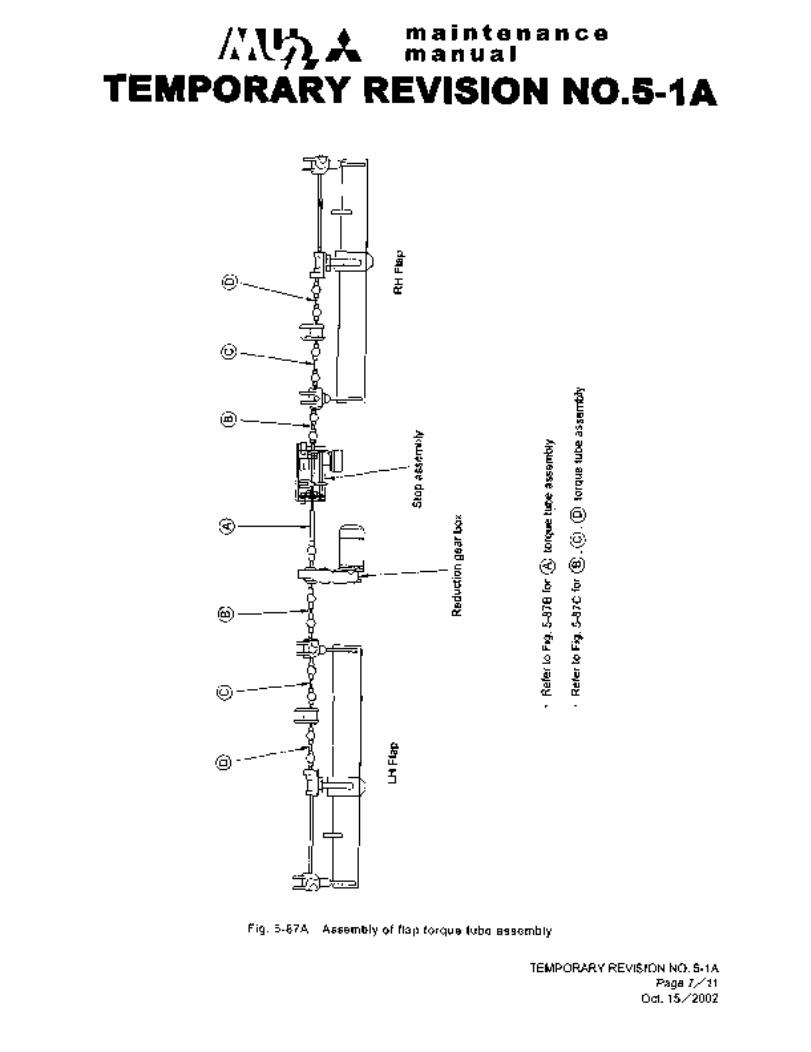
C~1;3ft maintenancemanual
TEMPORARY REVISION N0.5-~A
a
bI
O
r
Ir m
~E, rE n o
e, E an a,m 3
a m Pa a, avJ o
ga
s~iP,
c~u m oa, t~
CPu,rj,u. u-
9 gL L
L
O
n
d
I-I
Fig. 5-87A Assembly of flap torque tube assembly
TEMPORARY REVISION NO. 5-1A
Page 7/11
Oct. 15/2002

maintenancem a a a a I
TEMPORARY REVISION N0.5-LtA
Cotter pin (Ref.)(For existing shaft spline)
Grease (MIL-G-23827) Stop assembly
u,l,~m
Mating mark Torque tube assembly
01111 11110 1 YX o
o o
Inspection hole
AG.276 in. (7 mm)
Grease (MIL-G-23827)
Reduction gear box B
New cotter pin hole Approx.90"
Inspection hole
Shaft spline ii (for reduction gear box shaft side)
Existing cotter pin hole
Reduction gear box shaft
Section A-A
Fl,. 5-878 InstallationlRemoval of center flap torque tube assembly
TEMPORARY REVISION NO. 5-1A
Page 8/11
Oct. 15/2002

mainten ance
manual
TEMPORARY REVIS16N N0.51tA
Grease (MrL-G-23827) Shaft (Retainer ring side)
S~haft spline (Cotter pin side) Retainer ringCotter pin
A~ MdngmshGrea~e (MIL-G-2382:I
Inspection hole Shaft spline (Retainer ring side)
O 1111 1111 O1 YA 101111 1111 O
.276 in. (7 mm) Tor;lue tube assembly .080 .20 in. (2 5 mm)´•
.LMating mark
Shaft (Cotter pin side)
New cotter pin hole Approx.
Y~i:
Inspection hole
Shaft spline (Cotter pin side) iiExisting cotter pin hole
Section AIA
Fig. 5-87C Installation/Removal of outboard flap torque tube assembly
TEMPORARY REVISION NO. 5-1A
Page 9/11Odt. 15/2002

maintenancemanual
TEMPORARY REVISION N0.5111A
Shaft spline (Stop assembly side)
Shaft spline (Reduction gear box side)
Bolts
Bolts
O
WILz
Torque tube assembly
Shaft spline lengthL1 L2
’orque tube assemblyefer to Fig. 5-87A)
.45 in. (11.5 mm) 2.56 in. (65.0 mmj
;;3Fig. 5-87D Required value of shaft spline insertion (1/2)
TEMPORARY REVISION NO. 5-1A
Pgge 10/11Oct. 15/2002
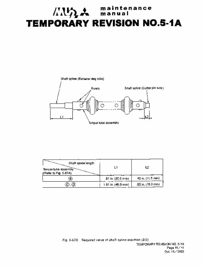
C~5mainte nance
manu al
TEMPORARY REVISION NO.5-IA
Shaft spline (Retainer ring side)
Rivets Shaft spline (Cotter pin side)
.O O O
~IL21
Torque tube assembly
Shaft spline lengthL1 L2
i~rque tube assemblyRefer to Pig. 5-87A)
.81 in. (20.5 mm) .45 in. (11.5 mm)
1.81 in. (46.0 mm) .63 in. (16.0 mm)
Fig. 5-87D Required value of shaft spline insertion (2/2)TEMPORARY REVISION NO. 5-1A
Page 11/11
Oct. 15/2002
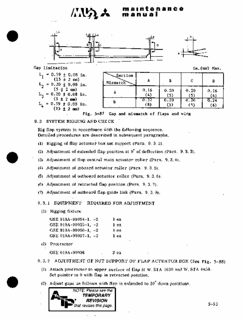
_~ a ia;mit~ all a ai Ob ;es´•8
Gap limit~8tibh ia.(rmn) -Max.
L1 0.59 -t 0.08 in.
(1~ mijn) A B C D
Z~2MiSmaf~h‘
I 0:20-f 0.08 in; I
(j f2 mm)a
0.16 0.2b 10.26 0.160.20 f 0.08 In.L3 (4) (5) (5) (4
(5 ~t 2b
0;32 0.20 0.20 0.24
Lq 0.59 ;t 0;08 in. (8) (5) (5) (6)(15 f 2 mm)
Fig. 5~8j ’~i;gp and iismatch ~f flaps and wing
9. 3 SYSTEM RIGGING AND CHE%K
Rig flap system in accordance ~Nith the following sequence.
Detailed prdcedures are described in subsequent paragraphs.
(1) Rigging of flap actuator box nlit support (Para. 9. 3. 2).
(2) Adjustment’of extended. flap position at 0 of deflection (Para. 9.3. 3).
(3) Adjustment of flap central main actuator roller (Para. 9. 3. 4).
(4) Adjustme~nt of inboard~ actuator roller (Para. 9. 3. 5).
(5) ~Adjustment of outboard actuator roller (Para. 9. 3. 6).
(6) Adjustment´•of retractedflap position (Para. 9.3. 7).
(7) Adjustment of outboard flap guide link (Parla. 9. 3. 8).
9.´•3. 1 .EQUIPMENT REQUIREDFOR ADJUSTMENT
(1) Rigging fixture
GSE 010A-99054-1, -2 :lea
´•GSE 010A-9055-1, -2: 1 ea
GSE 010A-99056--1, -2 .lea
GSE 010A-99057-1, -2 1 ea
(2) Protractor
GSE 010A-99036 2 ea
9. 3. 2 ADJUSTMENT OF NUT SUPPORT OF FLAP ACTUATOR BOX (See Fia. 5-88)
(I) Attach protractor to upper surface of’flap’:at´•W, STA 1630 and WI STA 4450.
Setpointer to 0 with flap in retracte’d position.
(2) Adjust gaps as follows with.flap in extended to-200 down’positions.NOTE: Please see the
TEMPORARY
~ee REVISION
L that revises this page.5-53

a i’~ t a n C ano a ijl a a
(a) Gap when nut Support set to one side:0 in.
(b) Gap between guide rail and side shoe: 0; 008~ 0. 016 in.
(c) ~easdre gap of 0.008 +0.002/-0.004 in. (0;2~+0.05j-0.linm) between
the guide rail and roller with the flap at 200 and 400 down pbsition.The gap may be adjusted by removing the retainer and adjusting the
eccentric bushing.
(3) After adjustment is completed, apply alignment mark to eccentric.bushing.Install safety wire on retainer attaching bolt.
NOTo
(i) When measuring flap deflection, lift flap by hand
to eliminate play in flap system.
(ii) Flap may be operated by hand by disconnecting
torque shaft between flap motoi´• and stop
assembly, or disconnecting torque shaft between
stop assembly and inboard actuator. Flap may
be operated by motor after all adjustments are
completed.
41234
~I
1. Retainer 4. Guide-rail 7. Jack nut block
5 6 7 8 9 1021 Eccentric ,5. Gear box 8. Gimbal
bushing 6. Roller 9. Jack nut-
3. Side shoes 10. Jack screw
Fig, 5-88 Adjustment of jack nut block
9. 3. 3 ADJUSTMENT OF EXTENDED FLAP POSITION
(1) Disconnect torque- shafts connecting stop assembly with actuator on R. Il. and
flap main reduction gear with inboard actuator on~-L. H; Plade~ flap in fully
extended position´•´•by rotating torque shaft by hand.
(2) Check rollers- of central main actuator and inboard and outboard actuators
for contact with guide rail.
(3) Discbnnect torque tube from inbojrd actuator geak´• box at W. STA 664.
Rotate actuators individually by hand so that rollers contac’t with guide rail.
Disconnect flexible shaft from central main actuator gear box.
(At this time, adjust the number of washers in Fig 5-86so as not
to cause twisting between inboard and outboard flaps. Reassemble
torquetubes and flexible shaft.) (See Figs 5-89 and 5-90)
5-54

.i~a a is.pi Ipt e naR ia~uin ;iie~ H 5 a s
MQTE
ORIGINAL Tiaten flbliibi~ shlift: fih8et:.tighti hsta~i´•i"
As Received By safety wire. If fleki~b´•ie Qh;pft is tighteiied6~ ~haft inay riot
AT P Be corlve~ied p~odthly, to Poiiitibn
Beai eve? shaft nut 8nd secure with tie strdij
.´•rii’´•.
Pig. 5-89 Disconnect torquetube Pig. 5-90 Remove flexible shaft
9. 9. 4 ADJUSTMENT OF ACTUATOR ROLLER (See Pig. 5-91)(1) Place flap in 200 azid 4q0 down position by´• rotating torque shaft by hand
at the inboard: actuator gearbox. Adjust the aft roller and jack supportto 0.008 +0.002/-0.004 in.(0.2 +0.05/-0.1 mm) by removing the retainer-
and adjusting the eccentric bushing.(2) Extena~’the fiap’by hand to 2/3 position on the guide´•rail from 00 and
adjust the gap between the forward roller and guide rail to 0.008
+0.002/-0.004 in. (0.2 +0.05/-0.1 ms) by removing the retainer and
adjusti~g the eccentric bushing,
(3) After adjustment is cbmpleted, apply alignment mark to eccentric bushing.Install safety wire on retainer attaching bolt.
2 3 4 5 6 7. g
00
1. Guide rail 4. Retainer 7. Ii~ar roller
2. Front roller ´•5. RRtainer 8. Jack support3; Eccentric bush 6. Eccentric ~bushing
Fig; 5-91 Adjustment of main actuator roller
5-55

malnfenancem a a us I
9. 3. 5 ADJUSTMENT OF INBOARD ACTUATOR ROLLER (See Pig. 5-92)
(1) Place flap in 200 and 400 down position by rotating the torque shcift at
the jnboard actuator gearbox. Adjust the gap between the aft rolle~ and
guide rail to 0.01 $0.004/-0.006 in. (0.3 +0.1/-0.15 mm) by adjustingthe eccentric bushing.
(2) Extend the flap by hand to 2/3 position on the guide rail from 00 and
adjust the gap between the forward roller and guide rail to 0.01 +0.0041-0.006 in. (0.3 +0.1/-0.15 imn) by adjusting the eccentric bushing.
(3) After adjustment is completed, apply alignment mark to eccentric bushing.
z 6 4 5i 3 4 5 7
3 7 8 2 6
i. Plate 5. Guide rail i. Front roller 5. Rear roller
2. Front roller 6. Retainer 2. Eccentric 6. Eccentric
eccentric bushing 7. Roller bushing bushing
3. Retainer eccentric bushing 3. Retainer. 7. Guide rail
4. Rear roller .8. Retainer 4. Retainer
eccentric bushing
Pig. 5-92 Adjustment of inboard Pig. 5-93 Adjustment of outboard
actuator roller actuator roller
9. 3. 6 ADJUSTMENT OF OUTBOARD ACTUATOR ROLLER (See Pig. 5-93)
(1) Place flap in 200 and 400 down position by rotating torque shaft by hand
at the outboard actuator gearbox. Adjust the gap between the aft roller
and guide rail to 0.01 +0.004/-0.006 in. (0.3 +0.1/-0.15 mm) by adjustingthe eccentric bushing.
(2) ~Extend the flap by hand to 2/3 position on the guide rail from 00 and
adjust the gap between the forward roller and the guide railto 0.01
+0.004/-0.006 in. (0.3 +0.1/-0.15 mm) by adjusting the eccentric bushing.
(3) After adjustment is completed, apply alignment mark to eccentric bushing.
9. 3. 7 ADJUSTMENT OF RE~RACTED FLAP POSITION (See Pig. 5-94)
(1) Place’flap in retracted position.
(2) Attach flaplrigging fixture, on upper surface of wing. ~See Figs. 5-94 and 5-95)
Attaching positionW.STA 950 GSE 016A-99054-1, -2 1 ea.
W. STA1750 GSE 016A-99055-1, -2 1 ea.
W. STA3150 GSE 016A-9~056-1, -2 1 ea.
W. STA4750 GSE 016A-99057-1, -2 1 ea.
5-56

as a ii.t B n ´•t:jO;BI ri ia a I
(3) ]Ciisconnect flexible shaft at dehtral main actuator gear box.
Disconnect torqiie shaft at inboard actuator gear b´•ox.
’(4) Rbtate inboard and outboard jack screws individually, and place them iii
retracted position. i’rim flap trailing edge.
~w. STA ~5T) 0; 04 in. (1 mm) Min; W. STA 1750 b. 04 in. (1 mm) Ri[in.
in~. STA ~150 0. 08 in..(2 mm) Min. W~‘STA 4750 0. 12 in. (3 mm) Min.
Measure flap trailing edge against rigging fixture, and verify the gap between
flap ~8xtension and ret~gcti0ri as specified above; Tile gap is adjusted byr6tating ja~k screw.
ORIGINAL ´•,Lt
As Received ByAT P
Gap between flap~.retraction and
extension
L1 0. 2 f 0. 12 in. Difference between L. H. and ´•R. H. 0. 12 in. (3 mm) Max.](5 3 mm)
Lz 0. 2 f 0. 16 in. 1~ (I
i(5 4 mm)
L 3 0. 06 +0.0 8 2-0.04 in.~(1.5 _Imm)[’ r, i
La Uniformly contact with flap surface
Fig. 5-94
W. STA. 950
W.STA.1750
W. STA. ´•31 50
W. STA. 4750
Fig. 5-95 Installation~of flap rigging fixture
(5) ´•Adjust’gap between flap and rigging fixture L1 and Li.
.(6) Adj ust gap-between flap and;upper surface of wing trailing edge.
(7) pdjust gap betweenflap and seal ´•reta;iner on lower surface´• of wing trai~ingedge.
5-57

c~~t maintenancemanual
TrEMPORARY-REVISION N0.5-2This Temporary Revision No. 5-2 is applicable to the following Maintenance
Manuals
MODEL NO. REPORT NO. FAG E
MU-2B-35/-36A MR-0218 5-58
MU-2B-60 MR-0336 5-58
Insert facing the page indicated for the applicable Maintenance Manual above.
Retain this Temporary Revision until such time as page is revised per the
change below.
REASON To change and add the removallinstallation of flap torque tube
assembly.
CHANGE Revision of NOTE next to Paragraph 9.3.7.(15) and addition of
Fig.5-96A and 5-968 as follows.
(15) Connect torque shaft which leads to flap stop assembly to inboard actuator gear box. (REF)
NOTE
When-replacing or reinstalling the flap flexible shaft,~install the short end ferrule
to main flap gear box side. (See Pig. 5-96A) Aircraft that have the flap flexible
shaft installed with the longer end ferrules attached to the main flap gear box side
are acceptable provided that 8.7 inches minimum radius is maintained.
ii Tighten flexible shaft finger tight. Overtightening of flexible shaft may hinder
smooth rotation of the shaft. Make sure that the bending radius of flexible shaft is
more than 8.7 in (221 mm).
iii When the flexible shaft is installed and safety wired, apply sealant around the
connections as follows. (See Pig. 5-97B)
iv When connecting torque shaft, do not change alignment of flap with wing. Install
retainer ring and cotter piniecurely. Ensure engagement of over 0.28 in. (7.1 mm) in
depth. (See Fig. 5-95)
v The flap cable should be degaussed prior to installation.
TEMPORARY RNISION NO. 5-2
Page 1/2
May. 15/2000

c~sh maintenancemanua~
TEMPORARY REVISION N0.5~2
rLongend fenule I Short end fermle
Flap gear-box Main flap gear box
(OUTBD side) (INBD side)
Pig. 5-96A
Main ffap gear box
Sealant PR-~442 (REF)
Sealant
Pig. 5-968
TEMPORARY REVISION NO. 5-2
Page 2/2
May. 15/2000

~i gl~nt ~i n i n b on~i i ii Irf a I
(8) Adjust mismatches between flap and central main actuator box assembly, and
between outer end of nap and wing in´• accordance witii Fig. 5-87.. C(9) Adjustments described in (5), (6), (7) and (8) above are possible b~ means of
eccentric bushing on bolt incorporated in central main actuator box ass;emblyfor attaching-inboard and outboard flaps.
(10) Tentatively reassemble torque shaft and flexible shaft.
(11) Retract inboard and outboard flaps as a unit until flaps contact with structure
by rotating torque shaft, Rotate torque shaft in opposite direction by one and
a half tdm. Ensure flap trailing edge being trimmed as specified in paragraph
(5~ above. Ensure gaps conforming to limits specified in paragraphs (6), (7)and (8) above. If those limits ~re not complied with, readjust positions of jackscrew and eccentric bushings.
(12) After position for retraction of flap is adjusted, tighten inboard and outboard
flaps that were tentatively assembled. Install flap attaching bolt and retainer
of eccentric bushing. Install. safety wire, cotter pin and apply alignment mark.
The tightening torque of flap attaching bolt is 52N 61 in-lhs(60-70 kg-cm),and that of the hollow bolt is 1300--1390 in-lbs(1498--1601 kg-cm).
(13) Ensure alignment of flaps with wing at inner end of inboard flap, outer end of
outboard flap and central actuator box.
(14) Remove rigging fixture from upper surface of wing. Replace screw in the
attaching hole for rigging fixture.
Q(15) Connect torque shaft which leads to flap- stop assembly,to inboard actuator
gear box.
NOTE
i Tighten:flexible shaft finger tight. Overtighteningof flexible shaft may hinder smooth rotation of the
shaft. Make sure that thebending radius of flexible
shaft is more than 8.7 in. (221 mm).
ii Position’water seal over shaft nut and secure
with tie strap (MS 3367-5-X).
iii When connecting torque ~haft, db not change alignmentof flap with´•iring. Install retainer-ring cotter pin
securely. Ensure engagement of’over’0.28 (7.lnrm) in
depth. (SeeFig. 5-96)
0.08 0;2 in. (2N5 mm)’
Serration I 0~ 28 in. (7. 1 mm) Min. CRetainer ring
NOTE: Pleaseseeijj~Flg. 5-96 Detail of serration fit
I TEMPORARYREVISION
5-58 ~that revises this page.

clr~ ctmaintenancemanual
9.3.8 RIGGING OF OUTBOARD FLAP GUIDE LINK (See Fig. 5-97)
(1) Attach protractor on upper surface of flap at W.STA 1630 and W.STA
4450.
(2) Tentatively fasten outboard flap to flap guide link with bolt.
(3) Place flap in retracted position.
(4) With flap in retracted position, adjust mismatch and gap as follows bymeans of adjusting rod and eccentric bolt.
(a) Mismatch between upper link and upper surface of wingi0.12 in. (3 mm) Max. (D)
(b) Mismatch between lower link and lower surface of wing+0.16 in. (4 mm) Max. (A)+0.1 in. (2.5 mm) Max.(B)
(c) Gap between roller and rail should be 0.010+ 0.004/-0.008 in.
(0.25+0.11/-0. 10 mm). (C)
Rear spar reference line
1 2 3 G 7
Upper surface
of wing
C
/I
/v
ly
I
A5 i. Adjusting´• rod 5. Connecting bolt
Lower. surface 2. Stop bolt and eccentric
of wing3. Upper link bushing4. Lowerlink 6. Roller
7. Rail
Fig. 5-97 Rigging of outboard flap guide link
(5) Place flap in 40" down position. Adjust gap between roller and rail
to less than 0.04 in. (1 mm) by means of Adjusting rod and eccentric Ibushing with the stop bolt fully in. After the mismatch and gap are
adjusted, install lock nut on bolt and apply alignment mark.
Gap between stop bolt and stop 0.02 to 0.06 in.(0.05 to 1.5 mmJ. (E)
(6) After adjustment of outboard flap guide link is accomplished, tightenouter flap attaching bolt. Install cotter pin.
5-2-94 5-59

maintenancemanual
9.3A SIMPLIFIED FLAP RIGGING PROCEDURES
NOTE
If the rigging fixture are not available, these proceduresare acceptable when the flap assembly is original and has
never been replaced. But, all other adjustment and riggingrequirements specified in Para.9.3 have been complied with.
(1) Retract the flaps.
(2) Ensure that the holes on the underside of the flap are inline with
the punch mark on the guide rail at both ends. Lay a straight edgeacross the holes to see if they line up.
(3) Ensure that holes drilled on the top of flap on each side of the
engine line up with the trailing edge of the wing.
(4) Mount a protractor on each flap.
(5) Advancethe flap to the first position of 5 (or 20) degrees with air
load (pull up) applied.
(6) Check the deflection.
(7) Continue to check at other positions.
CAUT ON
ONLY CHECK THE DEFLECTION GOING DOWN. DO NOT CHECK
DEFLECTION GOING UP.
(8) Ensure that all measurements meet requirements in Para. 9.3 of this
maintenance manual.
(9) Readjust flap as required.
(10) Remove the protractor.
9.4 ADJUSTMENT OF FLAP ACTUATING SWITCH
9.4.1 PREPARATION
Prior to adjustment, check flap for the following.
~1) L.H. and R.H. flaps for smooth movement by hand from retracted
position to 40" down position.
(2) Rollers at inner end, outer end and middle of flap for contact with
guide rail during the movement of flap from extended position to
down position. (See Para.9.3.3 of this manual)
5-60 5-2-94
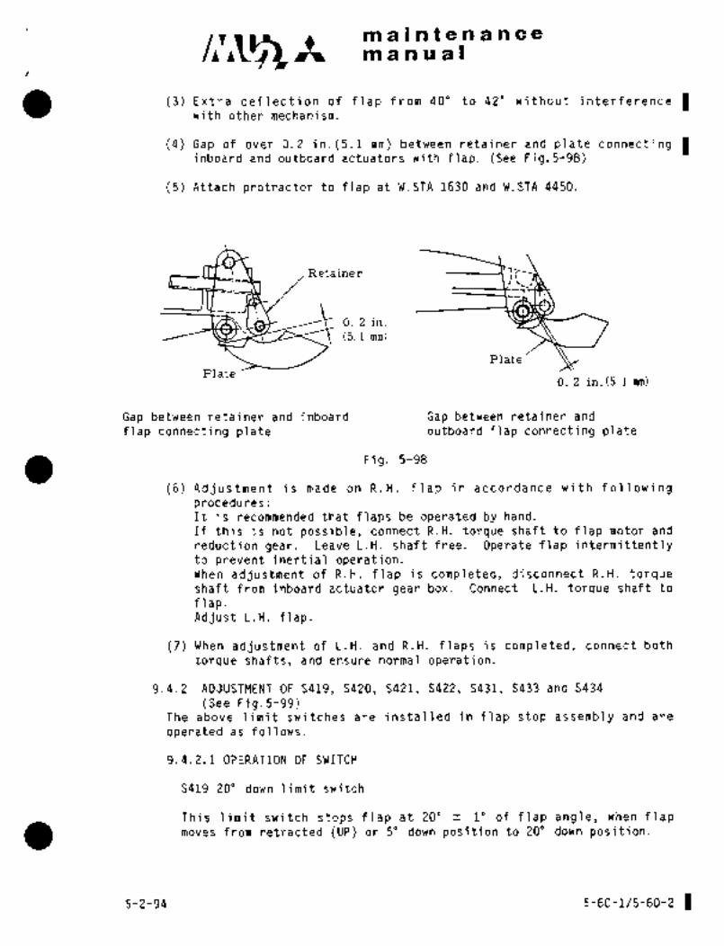
c,r~ ~tmaintenanceman a al
(3) Extra deflection of flap from 40" to 42" without interference Iwith other mechanism.
(4) Gap of over 0.2 in.(5.1 nm) between retainer and plate connectinginboard and outboard actuators with flap. (See Fig.5-98)
(5) Attach protractor to flap at W.STA 1630 and W.STA 4450.
Retainer -’’7;i´•
0. 2 in.
(5. 1 mm)
Plate
Plate0. 2 in.(5.1 mm)
Gap between retainer and inboard Gap between retainer and
flap connecting plate outboard flap connecting plate
Fig. 5-98
(6) Adjustment is made on R.H. flap in accordance with followingprocedures:It is recommended that flaps be operated by hand.
If this is not possible, connect R.H. torque shaft to flap motor and
reduction gear. Leave L.H. shaft free. Operate flap intermittentlyto prevent inertial operation.When adjustment of R.H. flap is completed, disconnect R.H. torqueshaft from inboard actuator gear box. Connect L.H. torque shaft to
flap.Adjust L.H. flap.
(7) When adjustment of L.H. and R.H. flaps is completed, connect both
torque shafts, and ensure normal operation.
9.4.2 ADJUSTMENT OF S419, S420, S421, S422, S431, S433 and S434
(See Fig.5-99)The above limit switches are installed in flap stop assembly and are
operated as follows.
9.4.2.1 OPERATION OF SWITCH
S419 20" down limit switch
This limit switch stops flap at 20" 1" of flap angle, when flapmoves from retracted (UP) or 5" down position to 20" down position.
5-2-94 5-60-1/5-60-~ 1

~n i8 c:int e tl 8 ~C
’s4i6 ~2" iiiiiit si~itZlh;jr’his: iik~ki?it switch stops flap at 22" ii i0 6f flap gngle, wi~eh Yiii~ves frorii
position to 20" cioci~n40 ion.
S4ii j" down li~it swithh
This liniit sivitch stops haP at 5"f 1" df flap angle, when flap moves from
UP position to ~a down i3ositi’on.
S4i2 6´° down limit switch
~jrhis limit switch hBij at 6" fl. 50 of flap angle, when flap moves
froin 40" or 200 down positiijns to 5" down position.
S43i puls~ operating limit Bwitch
This Ilniit switch makes pulse operatibn such as 1.5 seconds stop perone turn of pulse. ~perating cam´•wh8n flap moves from 00 DOWN to 200 DOWN
bt from 200 DOWN to"20 OWN.
8433 06 down limit switch
~is limitswitch stopsflap automatically for 1.5 secbnds-at 00 of
deflectionwhen flapmoves from 20’ DOWN.
5434 20 down. limit ’stjitCh
This limit swit~h i~eleases pulse operatiori autbmati~ally at i0 +10/-00of ’deflection when flap moves from 400 DOWN (or 200 DOWN) to UP.
01 P/. B
15
o \1 3
7 -8 10 9
i. aoodokn limitswitdh :Id. 50 down limii switch
.3. 200 dswn limit switch 11. 1VIechanical stop nut (DOWN side)3. 220 downlimit..switch _1 12. Lock washer
4. Uplimit :switch 13. Doiible Idck-nut
5,: Ddubte lock nut 141:- Ftap transmitte’r
6. Lock washer 15. .Pulse operating liniit switch
7. P?lechanical stop nut CUP-side) ~-16; Pulse operating cam
8. Moving arm 17. .20 down limit switch
9. 60 down limit switch .18. 00 downlimit switch
Fig. 5-99: Flap stopassembly
A6 5-61
orrt~\,Fn RY

in a i In f a a a a a 8m an a a I
9.4.2.2 FOR AD~USTMENT
(1) Conhe‘ct the ~ot8ting shaft between flap motor main reduction ge~irloox and stop
assembly so that the shaft may slide axially and smoothly.
(2) Discoilnect r6tatii~g shaft bf I;. H; flap f~om fiaip inotor main reduction gear
and inboard actuator. Disconnect rotatilig shaft of R. H. flap from stop
assembly and inboard actuator.
(3) Rotate shaft of flap stop assembly by motojr. Stop shaft at the position where
20" down limit switch (S´•4´•19) actuates.
(4) Set L; Il. and R. H. flaps at 20"f 1" of deflection by protractor.
(5) Connect L. H. flap with L. Il. rotating shaft.
(6) Place flap in extended position.
NOTE
Do not place flap in UP position, while UP ´•limit
switch has not been adjusted.
(7) Return flap from extended position to 20" down position.Check flaps for deflection of 20of lo and difference in deflection of less than
f 0. 5" between L. H. and R. H. flaps.If deflection is not within~specified range, adjust flap by relocating 20´° down
limit switch (S419) or by changing engagement of rotating shaft; serration.
(8) Gently extend flap by motor from 20" down position to 400 down position.Stop at 400 of deflection. Tentatively locate 400 down limit switch.
(9) Gently retract flap from 4’0" down position to UP. Stop at the position where
flap is aligned with wing at the alignment marks. Tentatively locate UP limit
switch.
(10) Gently retract flap from 40" down position to 200 down position.Stop at 22"fl" of deflection. Locate 220 down limit switch (S420).
(11) Gently, retract flap from 20" down position to UP. Stop at G"f 1. 5" of
deflection. Locate 60 down limit switch (S422).
(12) Gently, extend flap from UP to 50down position. Adjust the pulse operriting limit
switch and pulse operating cam so that the switch may be turned ON in the point"s" of cam.atl0 (+30’, -0) of deflection.
oThen adjust 2 down limit switch so
that the.switch may be turned ON at the position where the torque tube Is
returned back 0.5 turn to the UP directidn.
(13) Gently extend nap from UP to 5’ down position. Stop at~5’fl0 of deflection.
Locate 50down limit switch (S421).
(14) After ~uliustment of all limit switches is completed, actuate flap by motor.
Check for proper deflection at UP, 50 20oand 40" down positions.If de:flection is within specified range, fix limit switches securely.
eS) Adjust mechanical stop at UP and 40’ down positions.(See Para. 9. 4. 3 and 9. 4. 4 of this manual.
5-62

C~R nQi a Ci~ a a
Na fr
jIt b~ nbtei~ that S~19 "S420, which S4i9 d;enotes
di?fl8dtiori’oi~ flap tiith ttj4i9 ~ctuated, and S4i0 d~i?otes
deflec~olh df ~gp with S42b 8ctuat$d.It must be a1s6 noted that S421"S422, which S421
cieiiotes defl~ction df flap with S421 actuated; and
S422 denotes deflection of flap with 5422 actuated.
ADJUSTMEN?’ Oi~ UP LilLiIT SMiI;rdH AhTD UP POSITTON M~3 CI-IANICI\L S’1’OP
This limit switch autdmatically stops flap when flap mo\ies to retracted position
(OOf 1" of deflectioh);
(1) Place flap in retracted positiod, where flap comes in contact with wing
Structures, Return torque Shaft one and a half turns. Apply alignment: mark
to clarify’the flap position againSt wing trailing edge.
(2) Return torque shaft~an additional one turn by hand. TentBtively loc:lte UP limit
switch.
(3) After adjustment of UP limit switch is completed, normally operate flap bymotor, and allow flap to stop au’tomatically at UP position.
(4) At this position, set UP position mechanicai.stop nut to touch the moving arm.
Return stop nut one turn’. Stop nut must be away from moving arm by 0. 04
0. 005 in. (If 0; 13 mm). Tighten stop nut which is double nut to 250--350 in-lbs
(288^1403 kg-cm) torque using lock washer. Make sure that the lock washer
tabs securely catch the stop nut.
9. 4. 4 ADJUSTMENT OF 400 DOWN LIMIT SWITCH A ND ’DOWN;POSITIONMECHANICAL STOP
This limit ´•switch automatically stops flap when flap moves to ~0’0 down position.(40"~ I" df deflection).
(1) Extend flap by~hand to the pbsition: where flapcomes in contact with wingstructure.. Return torque shaft one and ahalf turns. Record the deflection.
(2) Return torque shaft ~an adhitional one turn. Locate 40" down limit switch.
(3) After adjustment of down limit switch is completed, normally operate flap bymotor, and´•’´•allow flap to stop -automaticaily at 40" own:position,
(4) At this position,.set 400 down side, mechanical, stop ~lnut to’ touc~i´• the moving arm.
Return stop nut, one:~turril Stop nut must be away from moving arm bylQ. 04 f
Or,005in..(l~I 0;1´•3 mm). Tig;h~ten’ stop’nut which i.s double nut to 25 0~35 0 in-lbs
(288 --403~kg-cmf td~que using iock.~washer. Make .sure that the lock washer
tabs securely catch the stop’nut.(5) Normally ope rate flap~ by motor. Allow ´•flap ~to stop automatically at 40" down
pdsition. Check f~jr.:clearance’ from´•´•the structure. (See Fig. 5-100) Gap between
jack: support and jack nut s~iould, be over 0. 2 in. (’5 min). Gap between nut support
End roller:under guide rail should be over 0. i ih.,(5 mm).
5-63
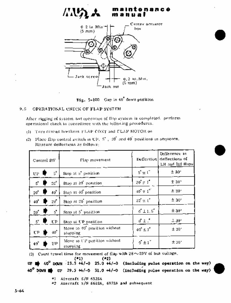
hi a C at a a a a c am a a a a I
Center actuator0. 2 in.Min:
box(5 mm)
Jack screw0, 2 in,Min.
’(5 mm)Jack nut
?Fi&. 5-100 Gap in 40e down position
9.5 OPERATIONAL CHECK OF FLAP SYSTEM
After rigging of system and operation of flap system is completed, perform
operational check in accordance ~ith the follo~ing procedures.
(1) Turn circuit breakers FLAP CONT and FLAP MOTOR on.
(2) Place flali control s~itch in UP, 5´° 20~ and 40~ positions in sequence.
Measure deflections as follon´•s:
Difference in
Control SW Flap movement I Deflection I deflections of
LH and liH flaps
UP 50 Stop at 5´° position 1 50 t 1~ f 30’
1~ 200 Stop at 20~ positidn 1 20´°+1’ f 30’
20´° 40" Stop position 30’
40. 1) 200 Stop at ’~d position 2~" 1" f 30’
20. P Stop at s. position 6.f1.5~’ I f30’
50 UP Stop at UP~position O~ -fi 10 1 f 30’
Move to 40" position without 400 4 1" 30’UP 400 stopping
40’positian\rithout o" f 1" I f 30’
(3) Count travel time for ´•movement of flap with 28rv29V of bus voltage,
(*1) (142)UP a. 400 DOWN 23.5 +4/-0 25.0 +4/-0 (including pulse operation on the way)
~o’ mm w 29.5 t~/-q SL.O ~/-O (I.c~ddg ~ulse ope~atloo on the re~) a~1 Aircraft S/N 652SA
*2 Aircraft S/N 661SA, 697SA ´•and :subsequent
5-~4´•.

’cti ci~ II ii t n d ii c Om a h ii ail)
Operil’ta flap t:untroi sivitdh. C:hdcl< cohi~oi sul´•fnce ilnil ilidic$toj´• light for
i=ont.rol Su rfxce I’nclic;~toi´• lightF1;1~ aontEbl S~iJ
vP Stop at r,etrricted p.ositibn CJ ri~eii
St;op at ~elloiv
Stuj~ at 20"
40ii .StdIj at i10" Yellon’‘I
(5) Check flny syst~in fordeformation; interference, strahge noise and smooth
movement over the entire range cif travel,
(6) Check torque: shafts and nctuntol´• guide rail for d:lmage.dheck lock nut, ~otter pin and I´•ctninei´• ring for I,i’oper installation,
(7) Check alignment marks for proper indication at mid point and at inner and
outer ´•ends of flap:
(8) Check flap jack ~crew and jack nut foi. lubrication,
9.Ii MEASUREMENT OF FLAP MOTOR CURRENT
Me~surement’of flk~ itiotor current should be made as necessary when
abnormal load is at:ted on flap control sjistem or major components of
this system are replaced,9.6.1 PROCEDURE´•
(1 Ite move a(:(: (:ss p;lnc:l´•s on w in Liiitl c~enfe r wing t rail ing edge.
(2) Discorlnect. ric wire 101 1)1 2) c:onnected to terminal of flap motoi´• relay10Cated nt L,. II, Side, centi!r wingCc,nnc´•ct the ai,ovo wire to positive sitle terminalof Shunt,
(3) Cdnnect.an electric wire~(MIL-W-5086 TYPE II AN-12) prepared for
measurenient to negative sicit: ter´•minal of shunt and flap motor relay.
FLAP MOTOR WIRESHUNT
20A MIL-W-5086C101D12 _I ´•nn 1 TYPE II AN-12-
Al! A2FLAP
MOTOR
~Ellap’Up Relay
Amme’r,er :(1 00´• Anp)
5-65

maintenanceman ual
TEMPORARY REVISION N0.5-3This Temporary Revision No. 5-3 is applicable to the following Maintenance
Manuals
MODEL NO. REPORT NO. FAG E
MU-2B-351-36A MR-0218 5-66
MU-2B-60 MR-0336 5-66
Insert facing the page indicated above for the applicable Maintenance
Manual.
Retain this Temporary Revision until such time as a permanent revision on
this subject is issued.
REASON To add wear limits for flap actuator jack screws.
ADD Paragraph 10.1. (1A) and table as follows after paragraph 10.1.
(1A) Flap actuatorjack screws
Maximum WearName of- parts inspected Inspection method
limit
Flap main gctuator jack screw Measure width of top of thread 0.06 in. (1.5 mm)
Flap inboard actuator jack screw Measure width of top of thread 0.032 in (0.8 mm)
Flap outboard actuator jack screw Measure width of top of thread 0.032 in (0.8mm)
TEMPORARY REVISION NO. 5-3
Page 1/1
Oct. 15/2002

d Ifll ii le~ a Im~ ii~ ten B h
´•po~er Buvi~h to ’’O~F;’i ijelor8 connectingwire. Cbnaect a wire to shunt and^ammetei´• so
as not to interfere with flap mechanism.
(4) Corin´•ct ~4re ffom shunt to ammiit~f teri;nitiai.
(5) Actuate flaps and measure current of flap motor carefully.
(6) Make sure that operating currents ai´•e as follows, except for a moment
.of starting.
Full dycle of flap uli operation 12 A or less
Full cycle of flap down´•operatfon 14 A. or less
(7) After measurement´•is completed, i´•emove ammeter, shunt and electri~
wire and restore the system.
to. WEAR LIMIT AND FREE PLAY ALLOWANCE
10.1 WEAR LIMIT
(1) Flap actuator jacknut
Name of parts inspected Inspedtion method Abrasion limit
Flap main acb~ator jack nut Measure width of top of thread 0. 04 i;l. 1(1 mm)
F’lap inboard actuator jack nut r, r, O. 032.in. (0. 8mm)
Flap outboard actuator jack nut ~1 t( 0. 032 in. (O, 8mm)
NOTE: Please see the
TEMPORARY
REVISION
I that revises this page.
5-66
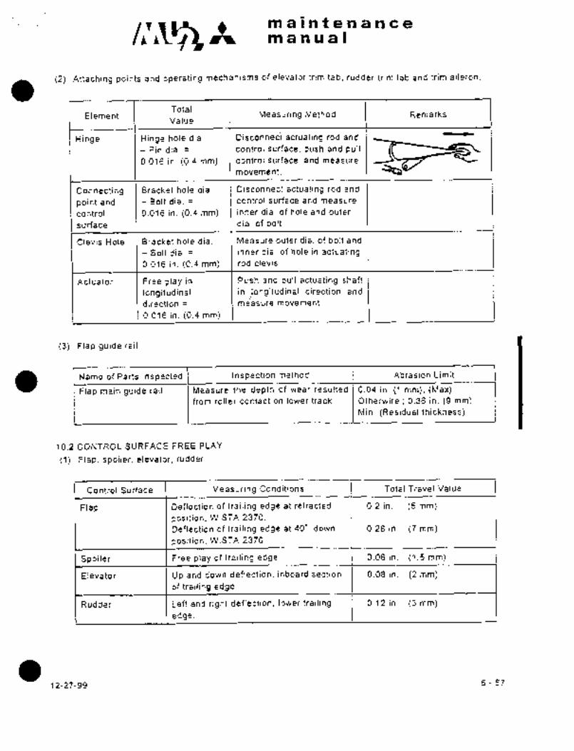
maineenanceIsr, man u’’a I
(2) Attaching points andoperating mechanisms of elevator trim tab, rudder trim tab and trim aileron.
TotalElement Measuring Method Remarks
Value
Hinge Hinge hole dia. IDisconneciactuating rod and
Pin dia. ’I control surface, push and pull
0.016 in. (0.4 mm) control surface, and measure
movement.
Connectihg Bracket hole dia. Disconnect actuating rod and
point and Bolt dia. control surface and measure
control 0.016 in. (0.4 mm) inner dia. of hole and outer
surface dia. of bolt
Clevis Hole Bracket hole dia. Measure outer dia. of bolt and
Bolt dia. I inner dia. of hole in actuating0.016 in. (0.4 mm) rod clevis.
Actuator Free play in Push and pull actuating shaft
longitudinal in /longitudinal direction and
direction measure movement.
0.016 in. (0.4 mm)
(3) Flap guide rail
Name of Parts Inspected Inspection method Abrasion Limit
Flap main guide rail Measure the depth of wear resulted 0.04 in. (1 mm), (Max)from roller contact on lower track Otherwire 0.36 in, (9 mm)
Min. (Residual thickness)
10.2 CONTROL SURFACE FREE PLAY
(1) Flap, spoiler, elevator, rudder
Control Surface Measuring Conditions Total Travel Value
Flap Deflection of trailing edge at retracted 0.2 in. (5 mm)
position, W.STA 2370.
Deflection of trailing edge at 40’ down 0.28 in. (7 mm)
position, W.STA 2370
Spoiler Free play of trailing edge. 0.06 in. (1.5 mm)
Elevator Up and down deflection, inboard section 0.08 in. (2 mm)of trailing edge.
Rudder Left and right deflection, lower trailing 0.12 in. (3 mm)
edge.
12-27-99 5-67
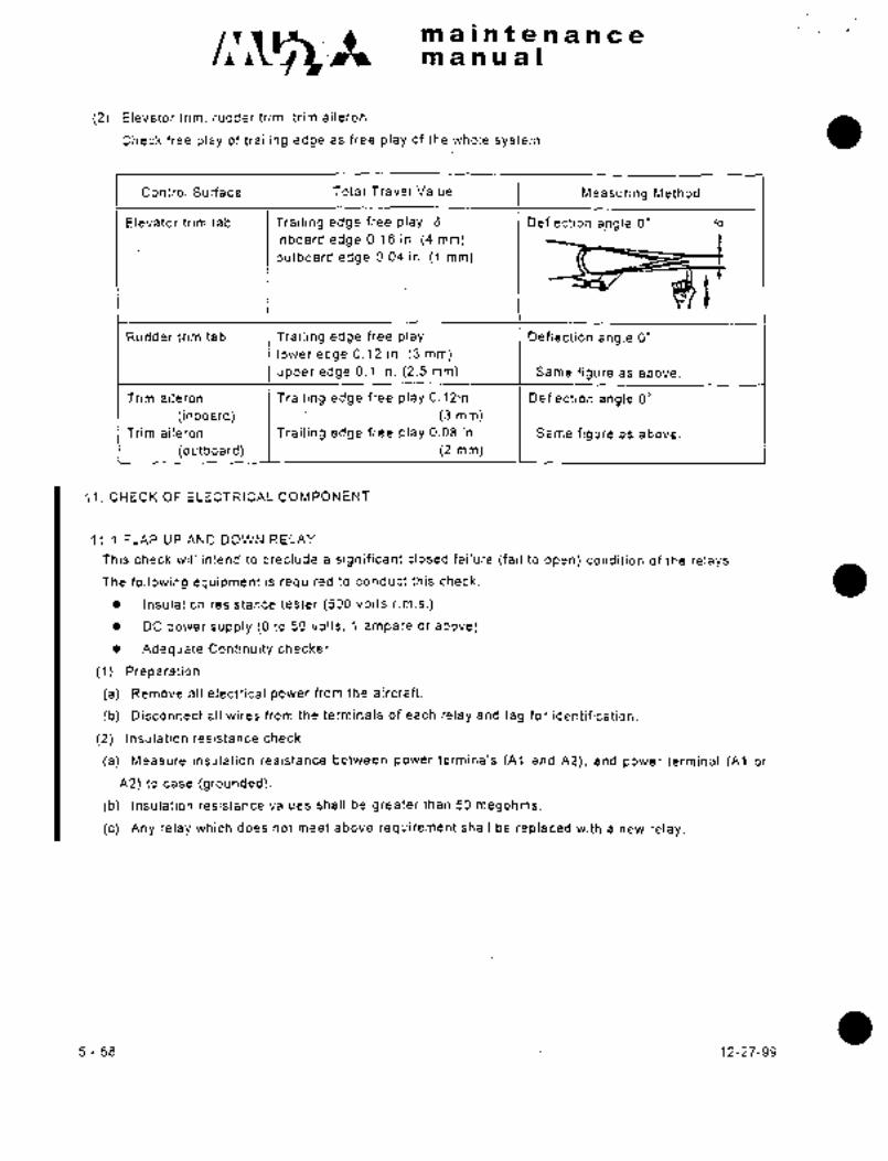
c,~l;s’ maintenanceII manual
(2) Elevator trim, rudder trim, trim aiieron
Check free play of trailing edge as free play of the whole system.
Control Surface Total Travel Value Measuring Method
Elevator trim tab Trailing edge free play 6 Deflection angle O’ a
inboard edge 0.16 in. (4 mm)outboard edge 0.04 in. (1 mm)
´•tRudder trim tab Trailing edge free play Deflection angle O"
lower edge 0.12 in. (3 mm)
upper edge 0.1 in. (2.5 mm) Same figure as above.
Trim aileron Trailing edge free play 0.12in. Deflection angle O"
(inboard) (3 mm)Trim aileron Trailing edge free play 0.08 in. Same figure as above.
(outboard) (2 mm)
11. CHECK OF ELECTRICAL COMPONENT
11.1 FLAP UP AND DOWN RELAY
This check will intend to preclude a significant closed failure (fail to open) condition of the relays.
The following equipment is required to conduct this check.
Insulation resistance tester (500 volts r.m.s.)
DC power supply (O to 50 volts, 1 ampere or above)
Adequate Continuity checker
(1) Preparation
(a) Remove all electrical power from the aircraft.
(b) Disconnect all wires from the terminals of each relay and tag for identification.
(2) Insulation resistance check
(a) Measure insulation resistance between power terminals (Al and A2), and power terminal (Al or
A2) to case (grounded).
(b) Insulation resistance values shall be greater than 50 megohms.
(c) Any relay which does not meet above requirement shall be replaced with a new relay.
5-68 12-27-99
c~s- maintenanceII manual
(3) Contact operation check
(a) Connect a continuity checker between the power terminals (Al and A2).
(b) Connect a power supply to the coil terminals Xl~pos.) and X2(neg.) and set voltage at 28 volts.
(c) Check for proper continuity I discontinuity in the energized and de-energized positions.
(d) Replace the relay with a new relay if this check indicates a failure.
(4) Restoration
(a) Remove the above test-equipment and reconnect the wires.
(b) Restore electrical power to the aircraft.
12-27-99 5-69 1

CHAPTER
POVVER PLANT

c~ Itmaintenancemanual
CHAPTER VI
POWER PLANT
CONTENTS
1. GENERAL DESCRIPTION 6- 1
2. CONSTRUCTION AND OPERATION OF ENGINE 6- 1
2.1 FUEL CONTROL SYSTEM 6- 1
2.2 LUBRICATING SYSTEM 6- 1
2.3 PROPELLER CONTROL SYSTEM 6- 1
2.4 ELECTRIC SYSTEM 6- 1
2.5 TORQUE SENSING SYSTEM 6- 1
2.6 ENGINE ANTI-ICING SYSTEM 6- 1
2.7 TORQUE AND INTERSTAGE TURBINE TEMPERATURE CONTROL SYSTEM 6- 1
2.8 FUEL PURGE SYSTEM 6- 1
3. REMOVAL, INSTALLATION AND OPERATIONAL CHECK OF ENGINE ACCESSORIES 6- 3
3.1 REMOVAL AND INSTALLATION OF TORQUE TRANSDUCER 6- 4
3.2 REMOVAL AND INSTALLATION OF TORQUE TRANSDUCER 6- 4
4. LUBRICATING OIL COOLING SYSTEM 6- 6
4.1 GENERAL DESCRIPTION 6- 6
4.2 BYPASS VALVE 6- 6
4.3 COOLING IN NACELLE 6- 6
5. ASSEMBLY OF ENGINE 6- 8
5.1 ASSEMBLY 6- 8
5.2 INSTALLATION OF EXHAUST PIPE 6-14
5.3 ASSEMBLY OF ENGINE MOUNT 6-14
5.4 INSTALLATION OF ENGINE EMERGENCY STOP MECHANISM 6-17
5.5 CONNECTION ADJUSTMENT OF ENGINE EMERGENCY STOP MECHANISM 6-18
6. INSTALLATION AND REMOVAL OF ENGINE 6-19
6.1 CONNECTION OF ENGINE MOUNT 6-19
6.2 CONUNECTION OF ENGINE EMERGENCY STOP MECHANISM 6-20
3-31-90 6-i

maintenancemanual
6.3 CONNECTION OF POWER CONTROL MECHANISM 6-20
6.4 CONNECTION OF CONDITION CONTROL MECHANISM 6-20
6.5 WIRING CONNECTION OF STARTER GENERATOR 6-20
6.6 WIRING CONNECTION OF FIRE DETECTING SYSTEM 6-20
6.7 WIRING CONNECTION OF ELECTRICAL SYSTEM 6-20
6.8 TUBING CONNE@rION OF LUBRICATING SYSTEM 6-20
6.9 TUBING CONNECTION OF FIRE EXTIGUISHING SYSTEM 6-22
6.10 TUBING CONNECTION OF FUEL SYSTEM 6-22
6.11 TUBING CONNECTION OF ENGINE BLEED AIR SYSTEM AN3 VACUUM SYSTEM 6-22
6.12 TUBING CONNECTION OF ENGINE TORQUE SENSING SYSTEM 6-22
6.13 REMOVAL OF ENGINE 6-22
7. RIGGING OF ENGINE CONTROL CABLE 6-23
8. CONNECTION AND ADJUSTMENT OF POWER CONTROL MECHANISM 6-24
8.1 CONNECTION 6-24
8.2 ADJUSTMENT 6-24
8.3 CHECK AFTER ADJUSTMENT 6-26
9. ADJUSTMENT OF CONDITION CONTROL MECHANISM 6-26
9.1 ADJUSTMENT AND CHECK BEFORE ENGINE INSTALLATION 6-26
9.2 CONNECTION ADJUSTMENT AFTER ENGINE INSTALLATION 6-27
10. ADJUSTMENT OF FRICTION LOCK LEVER 6-28
11. ENGINE OPERATING LIMITATION 6-29
12. TROUBLE SHOOTING OF ENGINE 6-33
13. PROPELLER 6-33
13.1 GENERAL 6-33
13.2 GENERAL DESCRIPTION 6-34
13.3 REMOVAL OF PROPELLER 6-34
13.4 INSTALLATION OF PROPELLER 6-37
13.5 PITCH ADJUSTMENT 6-38
13.6 MEASUREMENT OF PROPELLER PITCH ANGLE 6-39
13.7 REPAIRING CRITERIA OF BLADES 6-40
6-ii 3-31-90
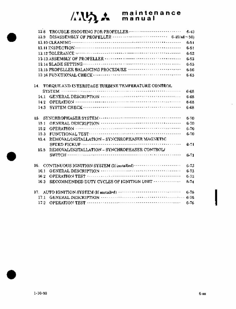
maintenancemanual
13.8 TROUBLE SHOOTING FOR PROPELLER´• 6-43
13.9 DISASSEMBLY OF PROPELLER 6-45(46 50)
13.10 CLEANING´• 6-51
13.11INSPECTION 6-51
13.12 TOLEPLANCE 6-52
13-13 ASSEMBLY OF PROPELLER 6-53
13.14 BLADE SETTING 6-55
13.15 PROPELLER BALANCING PROCEDURE 6-56
13.16 FUNCTIONAL CHECK´• 6-65
14. TORQUE AND INTERSTAGE TURBINE TEMPERATURE CONTROL
SYSTEM 6-68
14.1 GENERAL DESCRIPTION 6-68
14.2 OPERATION 6-68
14.3 SYSTEM CHECK 6-68
15. SYNCHROPHASER SYSTEM 6-70
15.1 GENERAL DESCRIPTION 6-70
15.2 OPERATION 6-70
15.3 FUNCTIONAL TEST´• t 6-70
15.4 REMOVAL/INSTALLATION SYNCHROPHASER MAGNETIC
SPEED PICKUP 6-71
15.5 REMOVAL/INSTALLATION SYNCHROPHASER CONTROL
SWITCH 6-71
16. CONTINUOUS IGNITION SYSTEM (If installed) 6-73
16.1 GENERAL DESCRIPTION 6-73
16.2 OPERATION TEST 6-73
16.3 RECOMMENDED DUTYCYCLES OF IGNITION UNIT 6-74
17. AUTO IGNITION SYSTEM (Ifinstalled) i 6-76
17.1 GENERAL DESCRIPTION 6-76
17.2 OPERATION TEST 6-76
1-10-98 6-iii
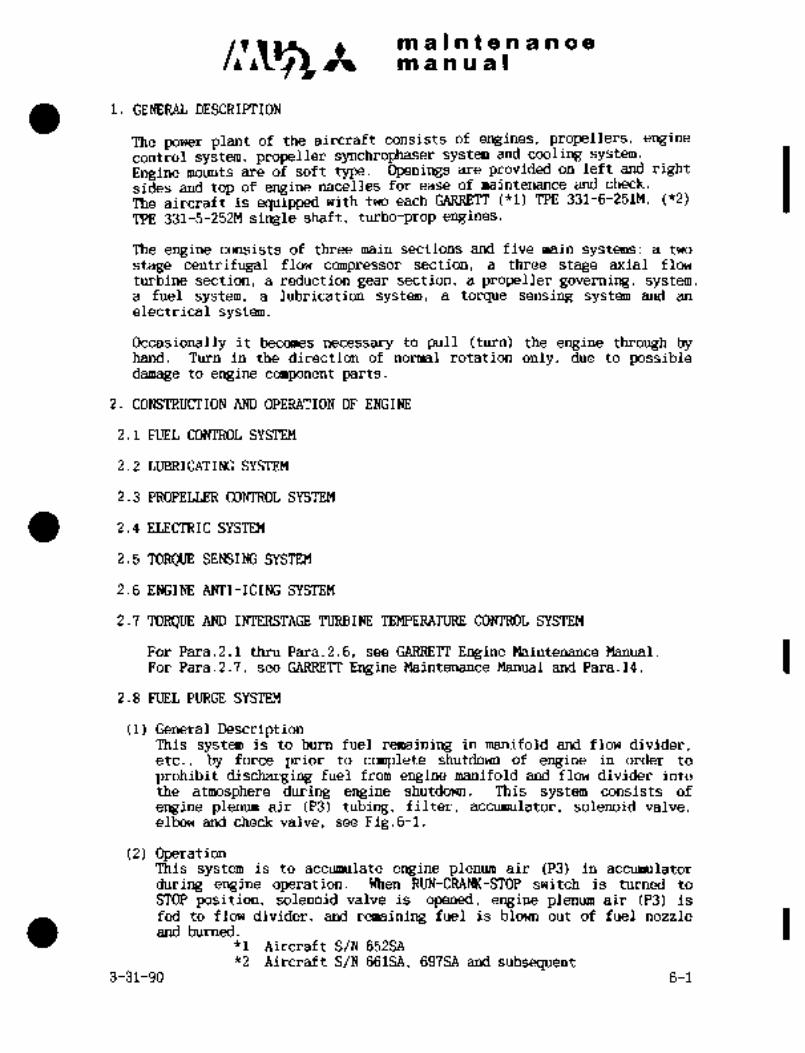
c~ Itmaintenance
1. GENERAL DESCRIPTION
The power plant of the aircraft consists of engines, propellers, enginecontrol system, propeller synchrophaser system and cooling system.
Engine mounts are of soft.type. Openings are provided on left and rightsides and top of engine nacelles for ease of maintenance and check:
The aircraft is equipped with two each GARRETT (*1) TPE 331-6-251#, ("2)
TPE 331-5-252M single shaft, turbo-prop engines.
The engine consists of three main sections and five main systems: a two
stage centrifugal flow compressor section, a three stage axial flow
turbine section, a reduction gear section, a propeller governing, system,a fuel system, a lubrication system, a torque sensing system and an
electrical system.
Occasionally it becomes necessary to pull (turn) the engine through byhand. Turn in the direction of normal rotation only, due to possibledamage to engine component parts.
2. CONSTRUCTION AND OPERATION OF ENGINE
2.1 FUEL CONTROL SYSTEM
2.2 LUBRICATING SYSTEM
2.3 PROPELLER CONTROL SYSTEM
2.4 ELECTRIC SYSTEM
2.5 TORQUE SENSING SYSTEM
2.6 ENGINE ANTI-ICING SYSTEM
2.7 TORQUE AND INTERSTAGE TURBINE TEMPERATURE CO~ROL SYSTEM
For Para.2.1 thru Para.2.6, see GARRETT Engine Maintenance Manual.
For Para.2.7, see GARRETT Engine Maintenance Manual and Para.l4.
2.8 FUEL PURGE SYSTEM
(1) General DescriptionThis system is to burn fuel remaining in manifold and flow divider,etc., by force prior to complete shutdown of engine in order to
prohibit discharging fuel from engine manifold and flow divider into
the atmosphere during engine shutdown. This system consists of
engine plenum air (P3) tubing, filter, accumulator, solenoid valve,elbow and check valve, see Fig.G-l.
(2) OperationThis system is to accumulate engine plenum air (P3) in accumulator
during engine operation. When RUN-CRAM(-STOP switch is turned to
STOP position, solenoid valve is opened, engine plenum air (P3) is
fed to flow divider, and remaining fuel is blown out of fuel nozzle
and burned.*1 Aircraft S/N 652SA
*2 Aircraft S/N 661SA, 697SA and subsequent3-31-90 6-1

maintenancemanual
5/
5 aZ
6 Ij
3 8
2
i. plenum chsmber P3 port 2. En~ine P3 line (engine side)
3´•i Air filter 4. Check valve
5. Accurauliitor 6. Solenoid valve
7. Elbow 8. Checkvalve
9. Flowdivider
Fig. 6-1 Fuel purge system
6-2

c~sm alntenancem a a a a I
DC 28V
Fuel
FUEL’SS1 DC 28VSHUTOFF I
VALVE
RUN-CRANK-
STOP SWITCH
FLOV3
DIVIDER CHECK SOLENOID
VALVE VALVE
Ic
ENGINE ACCUMU-
PLENUM LATOR
FILTERIVALVECHECKP3 AIR
Fire wall
REMOVAL, INSTALLATION AND OPERATIONAL CEIECK OF ENGINE ACCESSORIES
For this paragraph, see ´•AiResearch Engine Maintenance Manual.
NOTE
i ~To close the nacelle up~per door aftermaintenance
and inspection of engine, the stay must be fixed
surely with lockpin to the nacelle upper dooror
removed.and stored.
ii When work is done near plenum chamber in engine nacelle,air intake leading to front of oil cooler from nacelle
should be covered with a tape to keep foreign objects out.
6-3
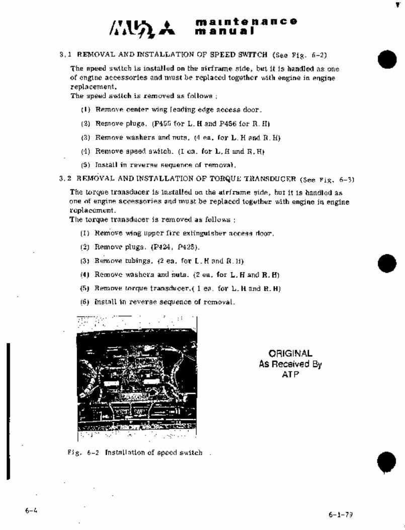
m a II at a n.a a a a
m a a a a I
The speed switch is installed on the airframe side, but it is handled as one
3.1 REMOVAL AND INSTALLATION OF SPEED SWITCH (See Fig. 6-2)
of engine accessories and must be replaced together with engine in enginereplacement.The speed switch is removed as follows
(1) Remove center wing leading edge access door.
(2) Remove plugs. (P455 for L. H and P456 for R. H)
(3) Remove.washers and nuts. (4 ea. for L. H and R. H)
(4) Remove.speed switch. (1 ea. for L´•. H and R. ii)
(5) I~stall in reverse sequ~nce of removal.
3.i REMOVAL AND INSTALLATION OF TORQUE TRANSDUCER (See Fig. 6-3)
The torque transducer is installed on the airframe side, but it is handled as
one of engine accessories and must be replaced together with engine in enginereplacement
The torque transducer is removed as follows
(1) Remove wing uppei´•’fire extinguisher access door.
(2) Remove plugs. (P424, P425).
(3) Remove ~bings. for L.X and R.H) a(4) Remove washers and nuts. (2 ea. for L. H and R. H)
(5) Remove´• torque transducer.( 1 ea. for L. H and R,H)
(6) Install in reverse sequence of removal.
ORIGINAL
As Received ByAT P
Fig. 6-2 Installation of speed switch
6-46-1-79

pn IlntenanceIIl a a -u a II
O Oo m ooo~ o 6h,
Fig. 6-3 Installation of torque trans-
ducer
a
6-1-796-5

nl a Inte 91 an a a
n9 a a a a i
.4. LUBRTCATING OIL COOLING SYSTEM
4. 1 GENERA L DESCRTPTION
The lubricating oil cooling system consists of fuel-oil heat exchanger, air-oil
heat exchanger and bypass valve. The fuel-oil heat exchanger located on the
side wall of the output housing transfers heat from lubricating oil to fuel.
Air-oil~ heat exchanger located beneath the exhaust pipe in the rear of nacelle
introduces air from L.H. and R. ii. air intakes and transfers heat from
lubricating oil to air.
.The bypass valve adjusts oil temperature and regulates pressure.
When ~oil temperaturerises, the valve closes; When oil temperature falls, the
valve opens to keep the oil temperature more than 131oF. When the pressure
between oil pLunp and air-oil heat exchanger rises due to blocking of the
exchanger, the valve opens and returns oil to oil tank. (See Fig. 6-4)
4.´•2 BYPASS VALVE (See Fig. 6-5)
Temperature and pressure settings of bypass valve are as follows:
Temperature settings ’150DF............ .Yalve is open.
1650F.............VaIve is fully closed.
Pressure settings10 psi Valve is closed.
(Oil temperature 900C)
40psi .....~......Valve is open.
4.3 COOLING IN NACELLE
Air introduced from air intake prevents temperatures in the following locations
from rising.
(1) Zone I
(2) ZoneII
(3) A.rea between nacelle side door outer skin and firewall
(4) Area between upper firewall and wing lower slirface
(5) Fire extinguishing container compartment
(6) Starter generator
6-6
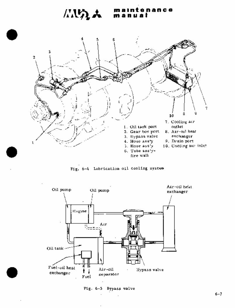
c~g It all ala4eaaacem a a a a i
4 5 6
2 1 i
c´•t~r:-a--...
C--~L/
d’ li?i:r
1I-
98i, 16
7. Cooling air"c"i. Oil tank port outlet
2. Gear box port 8. Air-oil heat
3. Bypass:valve exchanger
1 4. Hose ass’y 9. Drain port5. Hose ass’y .10. Cooling air inlet
6.´• Tube ass’y;fire wall
Fig.6-4 Lubrication oil cooling system
Air-oil he’atOil pump Oil pump exchanger
I~ngine
Oil tank
FuelLoil heat Air-oil B;rpass valveexchanger t~
separatorFuel
:Fig;:65. Bypass valve6-7

in a~ ~i t ;e h a h c:gm a a a at
5. ASSEMBLY OF ENGINE
5.1 ASSEMULYNOTE
For installation torque of bolts, niits, ti~bing ai~d
fi~tings, etc., in case of direct in~tallation of dii’
fram~ pafts onto engine and engine accessorieS,
see Engine Maintenance Manual unless otherwise
specified.
(1) Preparation
(a) Make -sure that engine is in the following conditiorl and adjust per EngineMaintenance Manual if necessary.
.Power control system
Fuel Control Unit PROP PITCH CO NT.
F/I Rig pin can be inserted.
Max. Stop 1000 10
Min. Stop Rig pin can be inserted.
.Condition control-system
Fuel Control Unit PROP-GOVERNOR
Max. Stop (420 f 10) Max. Stop
300 f 30 Min. Stop, micro adjusting screw and
arm G hit at the same time.
(b) Specific gravity adjustment
Perform specific gravity adjustment of fuel control unit depending
upon type of fuel used, in accordance with,Engine Zlaintenance Manual.
(c) Make sure that lever of fuel shutoff valve is in the position as shown
in Fig 6-22. If not, remove the -lever and reinstall so that the mark
on the shaft is as shown in the figure.
(d) Remove fuel line between fuel control unit and fuel shutoff valve and
install fuel flow transmitter. (See Fig. 6-7)
(2) .~nstall´•B-pressure switch, NTS check switch, and fuel pressure switch
with -adapter.
(3) Install tachometer generator. (See Fig 6-6) Tighten bolt(NAS1OZ1C4) to 65
70 in-lbs torque. Apply a light coating of grease(MIL-~-21164) on fit of
generator shaft.
(4) Install bracket for starter generator on engine mounting pads.Tighten nuts to 120Ni30 in-lbs. (See Chnpter~XLIIPara. 2. 2. 2)
6-8

s~n ´•iii ii .Pa ~jl d ORIGINAL
9n sna ii 4a L As Received ByAT P
~ebt ina~iiess adsi~inbly t~ of ea~h comp~nent.
~iistall einergeiidy s;tdp mBcha~iisin; ~or instal’iadon ahd iinic
se~ Para; 5:4.
(7) ie´•v~rs iro c’dntrol governor and u~derspeed governor
of thefu~i control Install engine shdck mount and engine mount
assembl~, see eara. ~.3.
(8) Install bracketitd engine mount assem~il3i Install unfeathering pump.
ApIj~ly safety wire oh fburattaching bolts, see Fig. 6-7.
Fig. ~-6 Installation of Fig. 6-7 Installation of un-
feathering pump andtachometer generator fuel flow transmitter
(9) Install tubes between unfeathering pump and engine, and unfeathering pump and
oil tank.
(10) Install engine bleed air duct, see Fig. 6-8.
(a) Tighten adapter of bleed air duct on engine plenum chamber, and gasket with
bolts. Installation torque is 40N50 in-lbs.j46-- 58 kg-cm).
(b) Install gasket on flange in front~of air bleed duct between N. STA 1300
to 1635 and connect duct with couplingInstallation torque for coupling is65 to 75 in-lbs. (75 to 85 kg-cm).
(11) Connect a test wire to magnetic drainplug at the bottom of engine output:
housing, see Fig. 6-9.
(a) Remove magnetic drain plug and install’ wire.
(b) Reinstall the plug and apply safety wire. Tighten the -plug and nut.to 90~
95 in-lbs. (104 h´• 109 kg-cni). Check magnetic plug for installation resistance.
(12) Installengine front cowling,’ see Fig. 6-10.
(a) Install an electric terminal block with two screws on cowling
(b) Install front cowling on engine. Tighten attaching bolts to 15N 20 in-lbs.
beforeinstallation of cowling, see Fig. 6-11.
(17^123 Irg-cm).
6-9(10)

clr~ m a Int a a a a a a
manual.
ORIGINAL
As Received ByAT P
Fig. 6-8 Installation of enginebleed air duct
i
Fig. 6-9 Installation of wire for Fig. 6-10 Installation of engine
magnetic drain plug cowling
(13) Install oil pressure transmitter.
(a) Install attaching bracket for oil pressure transmitter to cowling and install
oil pressure transmitter to bracket.
(b) Install tube between oil pressure output and oil pressure transmitter.
(14) Install engine oil bypass valve, see Fig. 6-12.
~(a) Place union, elbow and tee into bypass valve and install the valve with clamp
and bracket on output gear housing.
Apply a light coating of grease (VV-F-236) on O-rings used in union, elbow
and tee.
6-11

maintenanceman ual
Fig.G-ll Installation of terminal Fig.6-12 Installation of engineblock oil bypass valve
(15) Install cowling anti-ice line. (See Fig.6-13)(a) Tighten coupling nuts. And paint slipmarks on nut and sleeve
plumbing.(b) Apply safety wire to coupling nuts.
(16) Install bracket for brush block of propeller anti-icing.(See Fig.6-14)
(17) Install drain and vent lines. (See Figs.6-15 and 6-16)(a) Install drain line for start pressure regulator.(b) Install drain line for unfeathering pump.(C) Install drain lines for fuel control unit.
(d) Install vent line for oil tank.
(e) Install front and rear drain lines on turbine plenum and fastenwith clamps.
(f) Install drain line for input gear housing.
(18) Connect tubing and hose to torque sensor adapter.
j ORIGINAL
As Received ByI AT P
Fig.6-14prop. anti-icing brush block
Installation of bracket for
6-12 3-31-90
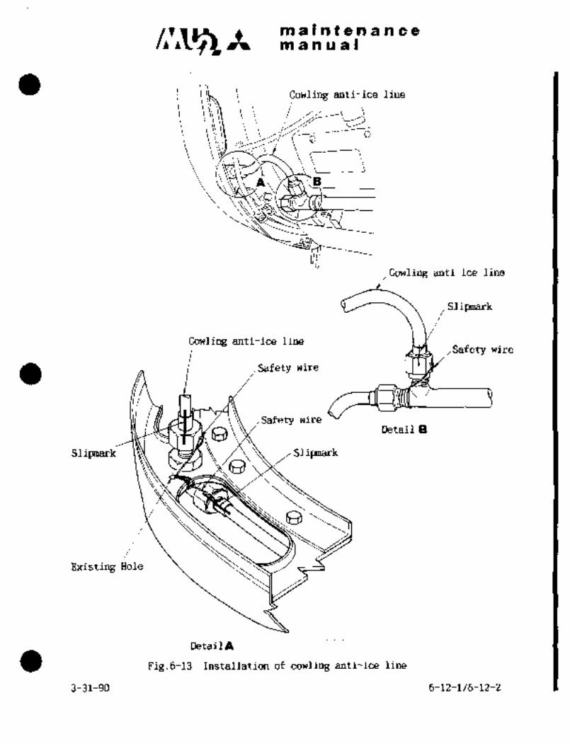
maintenancemanual
Cowling anti-ice line
Cowling anti-ice line
Slilrmark
Cowling anti-ice lineSafety wire
Safety wire
Safety wireDetail a
Slipanark 1~Y d~a Slipsnark
Existing Hole
Detai1A
Fig.6-13 Installation of cowling anti-ice line
3-31-90 6-12-1/6-12-2

ORIGINAL;9
As Received Byi:%gt’.~L.b, nria C e
AT P i.
:Ei~l
Fig. 6-15 installation of forward Fig. 6-16 Installation of gft
drain vent line -drain line
(19) Tnst:\ll engine: fire estin~uisher line (if Insfalled). (See ~Figs. 6-17, 6-18)
(a) Inst~nll cl;iml,s and brackets on circumference of "ZONE I’’tog~ether \vitli
engine outl,ul t~tiusing.
(b! Instnll Cl;lnlJ)S nllC1 brackets dn circumference of "%ONE II" \vjth
tulhine ]~lenurn att:lching~ bolts. Tighten bolt to 50--55 in-lbs(58-63 kg-cm).
(c) Instal:l.e!~gine Fi~e e?rtinguisher line and fixwith clamps.
(20) iiistnll fi~e de’tc~ctc,P.
(a) Fix sensing element attaching clips at brackets.around engine. ’Whenthebracket is tight8ned together with turbine plenum, tighten bolt to 50´•vfjg
.in-lbs.(58--63 kg-cm).N baE
Sensing element should be installed with grommet.
(b) Connect sensing element and flexible cable at three connector plugs.
i;.5i
~I
Fig. 6-17 Inst3ll~llon of fire Fig. 6-18 Inst:illation of ~fi l´•e
c,xtinguisher line~:in’ZONEI_
extinguisher line ill %0NE 11
(21) Inslali´•fuel piirgc: Yystem.
(22) fuel I,ros~ul:e transmitter, (See Fig. ’10-24)
(a) Install !-lrackt´•t fi,r´• fuel pressure transmiitc~.
6-13
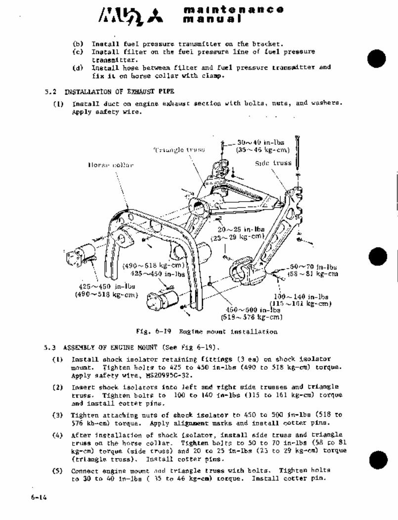
malnfgnancem a a a a.)
(b) Install fuel pressure transmitter on the bracket.
(c) Install filter on the fuel pressure line of fuel pressuretransmitter.
(d) Install hose bet~nJeen filter ai~d fuel pressure transmitter and
fix it on horse collar with clamp.
5,2 INSTALLATION OF PIPE
(1) Install duct on engine exhaus´•t section with bolts, nuts, and washers.
Apply safety wire.
30N40 in-lbs
Triangle truss X (35--46 kg-cm)
Eorse collar Side truss
1L,
iB20N25 in-lbs
(23h29 kg´•-cm!i
CZo (490- 518 kg-cm) 11 50/v70 in-lbs
425u45~ in-lbs \j~j\ 1 ~3 (56181 kg-cm
425´•´•´•450 in-lbs
(490--518 kg-cm) ldON140 in-ibs(115-vlsl kg-cm)
450^/500 in-lbs
(518-576 kg-cm)
Fig. 6-19 Engine mount installation
5.3 ASSEMBLY OF ENGINE MOUNT (See Fig 6-19).
(1) Install shock isolator retaining fittings (3 ea) on shock isolator
mount, Tighten bolts to 425 to 450 in-lbs (490 to 518 kg-cm) torque.
Apply safety wire, MS20995C-32.
(2) Insert shock isolators into left and right side trusses and triangle
truss. Tighten boltsto 100 to 140 in-1bs (115 to 161 kg-cm) torque
and install cotter pins.
(3) Tighten attaching nuts of shock isolator to 450 to 500 in-lbs(518 to
576 kb-cm) torque, Apply marks and install cotter pins.
(4) After installation of shock isolator, install side truss and triangle
truss on the horse collar. Tighten bolts to 50 to 70 in-lbs (58 to 81
kg-cm) torque (side truss) and 20 to 25 in-lbs (23 to 29 kg-cm) torque
(triangle truss). Install cotter pins.
(5) Connect engine mount and triangle truss with bolts. -Tighten bolts
to 30to 40 in-lbs 35 to 46 kg-cm) torque. Install cotter pin.
6-14

Rm ~P h ii a i
5.3:i b~ REA~ 6-2~)
(i) the i~diatoi´• Pdto ttie ili;st8il the cover; with irjoltiijwtisi~elis nuts aii~ ap~ly
(i) ’righteii the v~ith bolts, w8dher’~ and nuts and ~pljl5r cotter pins;
NQT~
instaliing the r’eak´• engine mdunt dn the air-
fram’e; place the over and
bracket with the faci~ig forward.
Isolator
Cover
*1 i
hing fitting
FWD
C7-/i Cutout
e -(Ref
.1 i
Bracket
Section A-A.
Fig. 6-2q :Assemb~Sr of rearengine mount

c~Amaintenancemanual
5.4 INSTALLATION OF ENGINE EMERGENCY STOP MECHANISM (See Fig. 6-21)
(1) Install support O of linkage together with forward attaching bolts of
compressor housing and connect bellcrank and rod 8.
Tighten the bolts to 50 to 60 in-lbs’(58 to 69 kg-cm) torque.Connection of bellcrank and rod is made by pin (MS20392-2C15) and
cotter pin.
(2) Install support O with forward attaching bolts of compressor housing.
7
2
1121
1. Pin 5. Pin 9. Rod 13. Feather valve
2. Rod 6. Bellcrank 10. Lever 14. Fuel shutoff valve
3. Bellcrank 7. Rod 11. Support 15. P3 Line
4. Pin 8. Rig pin 12. Support
Fig. 6-21 Installation of emergency engine stop mechanism
(3) Connect bellcrank O and rod O to support O of linkage.Connection of bellcrank and rod is made by pin (MS20392-2C15) and
cotter pin.
(4) Insert a rig pin into bellcrank
(5) Install rod O on feather valve O, adjust the rod length and connect
to bellcrank 0. Connection of feather valve O and rod O is made bypin (MS20392-2C15) and cotter pin. Make sure that connecting pin 6 of
bellcrank O and rod O is in the long hole edge near the shaft.
(6) Adjust lever of fuel shutoff valve to the position as shown in
Fig. 6-22.
(7) Adjust length of rod so that fuel shutoff valve is in "OPEN"
position.
5-2-94 6-17

ORIGINAL
m a i n t a a a a c a As Received Bymanual AT P
(8) Attach protractor to lever of fuel shutoff valve. (See Fig.6-23)
(9) Pull out rig pin.
Operational angle CLOSE
OPEN
,Mark on lever
on shaft
t level as installed
on the aircraftUP
Fig. 6-22 Installation of lever Fig. 6-23 Measurement of shutoff
valve lever operationalangle
(10) Move lever of fuel shutoff valve by hand to "CLOSE" position and
measure the following items:
Operational angle of fuel shutoff valve 87" to 93"
Travel of feather valve 0.24 to 0.405 in.
(4.5 to 10.3 mm)
When the above specified Values are not met.
(a) Readjust length of rod O connecting to feather valve O.
(b) Move attaching place of pin connecting bellcrank O and rod
O to change lever ratio and readjust.
(11) Set the lever of fuel shutoff valve to "OPEN" position and
ascertain that the rod O does not pull bellcrank 0.
(12) After adjustment, move lever of fuel shutoff valve by hand to "CLOSE"
and "OPEN" positions and ascertain that the lever moves smoothly.
(13) Make sure´•that clearance between P3 Line O (P/N 31011415-1) and rod
O/pin O is more than 0.125 in. (3mm). If not satisfied, the P3 line
and its attaching clamp/bracket should be installed at the position as
shown and adjusted to make more than 0.125 in.(3 mm) clearance.
5.5 CONNECTION AND ADJUSTMENT OF ENGINE EMERGENCY STOP MECHANISM
(1) Assembly and adjustment of the linkage of emergency stop mechanism
should be completed per Para. 5.4 before installation of engine on
aircraft.
(2) Move lever of fuel shutoff valve by hand to "OPEN" position.
6-18 5-2-94
C~5- Itmaintenancemanual
(3) Place condition lever of center pedestal to "TAXI" position, connect
engine and aircraft structure with rod 0. (See Fig. 6-41)(4) Move condition lever of center pedestal to the direction of "EMERG
STOP" so that a rig pin is inserted into "EMERG STOP" position of
cylinder ass’y.(5) Place condition lever to "EMERG STOP" position and lock it. Fuel
shutoff valve should be in "CLOSE" position and engine feather valve
in "OPEN" position. Adjustment is made by changing the length of
rod 0.
(6) Unlock condition lever and move to "TAXI" position. Fuel shutoff
valve is in "OPEN" position and engine feather valve in "CLOSE"
position. Make sure that clearance between pin and cam of cylinderass’y is 0.04 to 0.08 in. (1 to 2 mm). Adjustment is made by movingconnecting position of rod. (See Fig. 6-44)
(7) Move condition lever between "EMERG STOP" and "TAXI" positions and
check for smooth operation without any interference, contact,deformation and abnormal noise.
NOTE
When condition lever is moved to "EMERG STOP" from "TAXI",adjust the lever so that there is no abnormal heaviness or
obstruction in movement.
6. INSTALLATION AND REMOVAL OF ENGINE
Installation of engine should be performed as follows.
NOTE
When work is done near plenum chamber in engine nacelle,air intake leading to front of oil cooler from nacelle
should be coverd with a tape to keep foreign object out.
6.1 CONNECTION OF ENGINE MOUNT
(1) Hang up engine with a sling (GSE 016A-99024).(2) Install bolts (016A-13264) by setting engine front mount to mount
fitting of with leading edge. (See Fig. 6-24)Tighten nuts handtight and apply cotter pin on bolts.
NOTE
Attaching bolts of engine front and rear mount should be
inspected by magnetic particle inspection at every engineremoval if the previous inspection has not been conductedwithin 1,500 hours in service.
(3) Install bolts by setting engine rear mount to attaching fitting on
airplane. (See Fig. 6-25)Tighten nuts handtight and apply cotter pin on bolts.
NOTE
Apply a light coat of anti-seize compound (MIL-G-6711)on attaching bolts of engine rear mount to prevent seizing.
5-2-94 6-19

malnt a nane a.
m a a a a I
I
B~u!
Fig. 6-24 Connection of engine Fig, 6-25 Connection of engine
front mount rear mount
6.2 CONNECTION OF ENGINE EMERGENCY STOP MECHANISM
See Para. 5.5 (l)--(’i). ORIGINAL6.3 CONNECTION OF POWER CONTROL MECHANISM As Received By
See Para. 8, AT P
6,4 CONNECTION OF CONDITION CONTROL MECHANISM
See Para. 9.2
6.5 WIRING CONNECTION OF STARTER GENERATOR
6.6 WIRING CONhTECTION OF FTRE DETECTING SYSTEM (See,Figs. 6-26 and 6-27)
(1) Connect plug of flexible wire for fire detecting in "ZONE I" to connector in wing’
leading edge. Install safety wire on plug.
(2) Connection of flexible wire plug for fire detecting in "ZONE II", located at fire
wall of rear nacelle (N. STA1300), is performed after connection of engine air
bleed line.
6.7 WIRING CONNECTION OF ELECTRICAL SYSTEM (See Figs, 6-28 and 6-29)
Connect electric plug 5422 and 5428 (R. H. engine) and 5921 and 5427 (L. H. engine)
to connectors in wing leading edge. Install safety wire on each plug.
6.8 TUBING CONNECTION OF LUBRICATING SYSTEM
Install t~o hoses leading to oil cooler, in front of nacelle fire wall (N. STA790)
(See Fig 6-30),
6-20
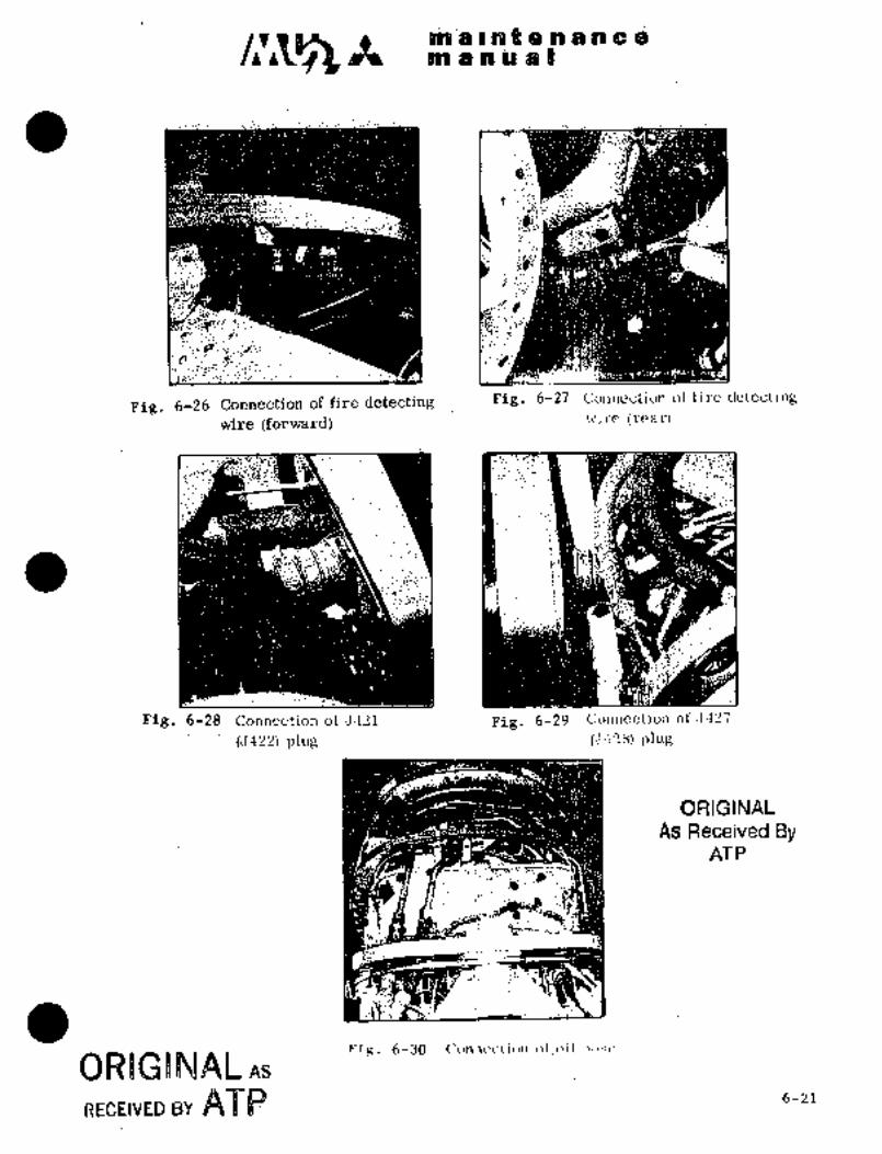
iP~l’g :1
ij~ a:~Jp a B
if~
1,
D~D
-k~:
Q1~ I’~"
Figi 6-26 Connection of fire d~tecting Pig..6-27 Connection of fire detecting
wire (forward) w~re (rear)
:;´•´•~i
Fig..6-28 Connection of 5421 Fig. 6-29 Connection ofJ~42’i
(5422) plug (j4",8) plug
ORIGINAL
As Received ByAT P
FIR. 6-30´•-
ORIGWNAL As
RECEIVED BY 6~8$$ 6-21

maintenancema nual
TEMPORARY RIVISION N0.6-1This Temporary Revision No. 6-1 is applicable to the following Maintenance
Manuals
MODEL NO. REPORT NO. PAGE
MU-2B-35/-36A MR-0218 6-22
Insert facing the page´•indicated above for the applicable Maintenance
Manual.
Retain this Temporary Revision until such time as a permanent revision on
this subject is issued.
REASON To change the inspection of the engine bleed air tube.
ADD Paragraph 6.11A as follows after paragraph 6.11 and the note.
6.11A Inspection of the engine bleed air tube 022A-964220-7
(1) Remove nut and screw from clip securing the engine bleed air tube.
(2) Disconnect the.tube from the adapter assy and the tube assy.
(3) Perform a pressure check to the tube using typical shop method with shop air (if possible,
use the air pressurized of 100 psig (7.1 kglcm’(4) If no leaks are found in the line, it may be reinstalled; If any leaks are detected, thetube
should be replaced with a new one.
TEMPORARY REVISION NO. 6-1
Page 1/1
Oct. 15/2002
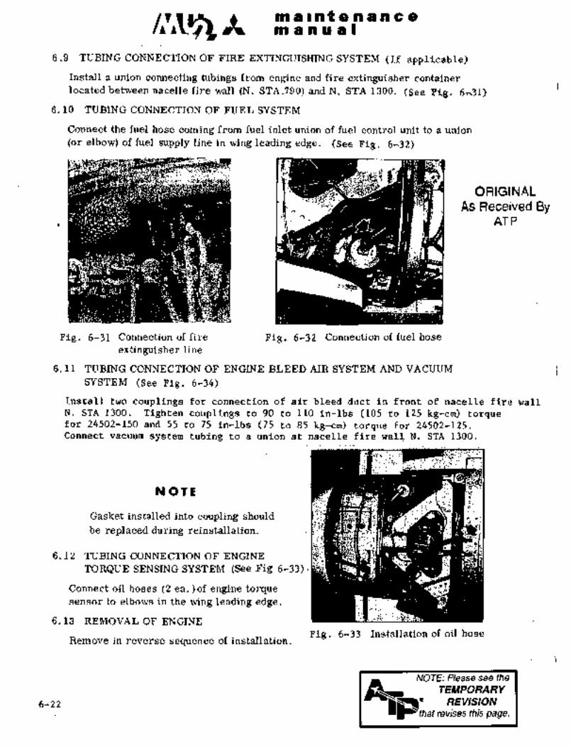
A see a I set g, n.ra se c ~p
see ta se se -a I
6.9 TUBING CONNECTION OF FIRE EXTINGIIISHING SYSTEM (:~f applicable)
Install a union connecting tubings from engine ahd rfire extinguisher container
located.between na’celle fire wall. (N. STA.’790):and N. STA-13bO. (See T-ig, 6r31)
6. to TUBING CONNECTION OF FUE~ SYSTEM
Connect the fuel hose coming from fuel inletunionof fuel control unit to a union
(or elbow) of fuel supplyline in wing leading edge. (See Fig. 6*32)
ORIGINAL
_.-:d As Received ByUI:l AT P
Fig. 6-31 Connection of fire- ´•Pig.’6-32 .C6nnedtiono~ fuel Slose
extinguisher line
6. 11 TUBING CONNECTION OF ENGINE´• BLEED AIR SY’STEM;AND’: VACUUM:
SYSTEM (See pig. 6-14)install two couplings ´•foy connection of air:lleea:´•dudt in front:ofnacelle fire wall
N. STA 1300. Tighten: couplings tb:90 to 1-10: in-lbs:(105 -to. 125 kg-cm) torquefor 2450?-150and 55 to 75 in;lbs:(75 to8’5 kg-cm) torquefor 24502-125.Connec’t vacuum system tubing to a union at nacelle fire wall. N. STA 1300.
NO TL
Gasket installed into coupling shouldbe replaced during reinstallation.
6. 12 TUBING ´•CONNECTION ’OF ENGINE
TORQUE SENSING SYSTEM´•:(See ´•Fig 6-33)~!
Connect oil hoses’(2 ea.)of engiae:tor;dluesensor to elbows in the wing:~eading edge.´•
6.13 REMOVAL OF ENGINE
Remove in reverse sequence of installation. :;-:Pig. 6-33 Installation of oil hose
NOTE: Please see the
TEMPORARY
REVISION
~that revises this page.

iiiii~i i b.~i8 ~8 a a 818 C
7. EiIGrfrjC: Z)F COP;jTROL CABILE
--´•´•1-~
(1) rig i~in into grm df p~lejr.Eissenibiy under enter pedestal an~
´•i-~---
fix puil.e3i and arin tb brailket,(Sce E’iB’. 8735~
(2) Insert rig pin ~into pulieji of puileyassembly located ’at the back of pressure
bulkhead. (F:ST~A8035) (See Fig. 6-36)
(3) Ihsert rig pin into bracket of pulleyassembly -located at upper part of rear
nacelie (wing rear spar)i ~and fix pull;ey.
(See Fig. 6-37)Fig. 6-34 Corinectionof airbleed
line
ORIGINAL
As Received ByAT P
Fig. 6-36 Insert rig pin into pulley
ass’y at STA 8035
Fig. 6-35
(4) Adjust power control cable and condition
control cable by turnbuckles so that the
cable tensions become the specified values.
For specified value, see Fig. 6-38.
Turnbuckles are located at the back of
pressure: b~ilkhead (F..STA8035) and rear
access panel of center wing.
turnbuckles and pull out rig pins.
(6) ’Check control Cabie for- specified clea:rance
from neighboring ´•structi~r;e gnd ´•for speci-fiedl alignment with pulley installition. Fig. 6-37 :Inse~t rig pin into pulley
´•ass~’y ~atj aft nacelle
6-23

malnQenan in a
m a a ri a I
kg: Ib
26 ~60
24
s: 22. 50
20 r~O9 ,e
6
E,6´•
9,18 ~40 cable 3/32"
iJ~ Is
1430
-10 0 10 20 30 40
Air t~mperature "C
Fig. 6-38 Control cable tensions
Cable deflection to pulley Max 2"
Clearance between cable and other Cable near pulley must be more than 0. 24
part s I in. (6.1 mm) away from structures or
installed equipment.
Cable between pulley or fairledds should
not contact with structures or equipments
Clearance between cable and electrical
line must be more than 0.47 in(11.9 mm).
Clearance between turnbuckle or cable
fitting and structures or equipmentsmust be more than 0. 75 in.(19.1 mm).
8. CONNECTION AND ADJUSTMENT OF POWER CONTROL MECHANISM
(See Fig. 6-41)
8.1 CONNECTION
(1) Set power lever of center pedestal to "FLIGHT IDLE" position.
(2) Set lower lever of propeller pitch control to "FLICHT IDLE" position on the
rigging plate.(3) Adjust rod O by turning turnbuckle to adjust rod length,~ and connect the
rod to upper lever of propeller pitch control. (See Fig. 6-40)8.2 ADJUSTMENT
(1) Set power lever to "REV%RSE" position.
(2) Insert rig pin into IREVERSE" position of propeller pitch control. When the
rig pin can not be inserted, move adjusting serration retainer to changelever ratio and readjust. To shorten one pitch of serration makes movement
of power lever larger approx. 0.16 in. (4.1 mm) on the dial of center pedestal.
(3) When power levers of L.H. and R.H. engines are~moved together, the difference
of each stroke should not-be more than 0.12’ in. (3 mm):on the dial of
center pedestal.
6-24

na ai s ii t B ~ra a a 6 a~n a a a si I
i4) Whenpower lever of center pedestal is set to and "REVERSE"Positions, adjust stops so that clearance of 0.08 to 0.16 in, (2 to 4.1 mm)is ~etweeh leve~ and stbps, (See Fig. 6-39)When cleai-ance df power lever is extremely different between-"TAKEO~F" Side
and "REV~ERSE" side, readjust by moving lever attaching serration of prop~llerpitch control to divide the clearance eqLialljr.
Power lever Check item
"FLIGHT IDLE"´•j "TAKEOFF" 0.08 to 0.16in. (2 to 4.1 mm)clearance betwee~ lever and stop..
"FLIGBT IDLE" -c"REVERSE" ~´•08 to 0.16 in. (2.to 4.1 mm)clearance between lever andst’op.
F´•~:
B 0.08 to 0.16 in. (2 to 4.1 mm)II
i 8 BLI~HT IDLE
ORIGINAL
As Received ByAT P
;ici´•
I /e>eA= 0.08 to 0.16 in.
~I (2 to 4.1 nrm)i ’Stop
Fig.~ 6-40 Power lever Fig, ~6-39 Connect rod to pitchcontrol arm (power control)
i. Rod 7. Cable drum 11: Rod ass’y
2. Lever 8. Retainer 12. Rod
3. Cyli~der ass’3r ´•9´• Lever 13. Turnbuckle
4. Rod (Ref. dimension 10; Rig´•:pin hole 14. Bellcrank8
3. 39 ~t 0. 02 in)~ 15 Rodass’y
5. Bell~crank 16. Lever
6. Rod 17. Rod
1 I I ~C \II
16
/-i
14
a,
12
13
IIMERO
sT.QP
TAXI
CRUISEii
Flg. 6-41 Adjustmentof´•engine controlsysteln TAITF OFF--LAND
6-25

sis is i a t $~n a a a Qsis a ii se ii I
NOT L
Adjustment of stops shohlci be performed aftermakingsure that no difference of stroke i~ in L. H.
and R. H. erigine poiYer levers.
8.3 CHECK AFTER ADJUSTMENT
(1) Move power levers of L. H. and R. H. engines from "TAKEOFF" to "FLIGHT
IDLE", and make sure that landing gear warning switch becomes "ON" at
position approx. 0. 2 in. (5 mm) before reaching "FLIGHT IDLE".
(2) Make sure that rig pin can be inserted into "FLIGHT IDI,E" positionon the rigging plate of propeller pitch control when power lever is set to
"FLIGHT IDLE" position.
(3) Make sure that a rig pin can be inserted into "REVERSE" position on the
rigging plate of propeller pitch control when power lever is set to
"REVERSE" position.
(4) Make sure that manual fuel valve lever is in contact with the stop properlywhen power lever is set to "TAKEOFF" position. If the lever is not in
contact with the stop, repeat rigging of fuel control unit and propellerpitch control.
9. ADJUSTMENT OF CONDITION CONTROL MECHANISM (See Fig. 6-41)
9.1 ADJUSTMENT AND CHECK BEFORE ENGINE INSTALLATION
(1) Set condition lever of center pedestal to "TAXI" position and fix lever withfriction lock.
(2) Set cylinder assry O to "TAXI" position and inse~i´•trigpin.
(3) Connect rod between bellcrank O and cylinder ass’y 0. Do not changelength of rod Connect by adjusting length of rod
Connection of rod and lever should be done at the tip of long hole of
lever.
(4). Pull out rig pin and loosen lock of
cbndition lever.
(5) Set condition levee to "TAKEOFF-LAND"
and "EMERG STOP" positions and make
sure that rig pins are inserted into each
rig pin hole on cylinder ass’y 0. If rig
pins can not be inserted, move adjust;-ing serration retainer at connection of
rod and lever to change lever
ratio and readj ust. To shorten one pitchof serration makes stroke 6f cylinderass’y O smaller approx. 0. 05 in. (1.3 mm);
Fig. 6-42 Connect airframe
and engine with rodORIGINAL
(condition control)As Received By
6-26 AT P
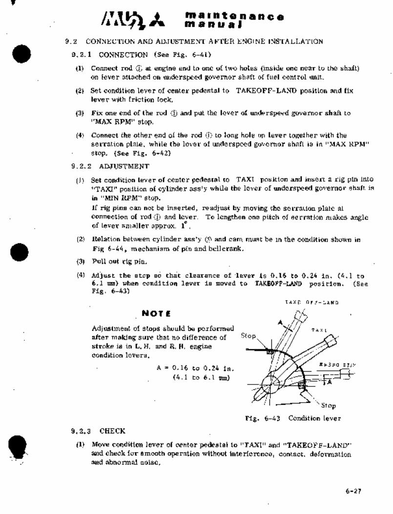
C~Z .nT a a r a a a a c anT anua9
9.2 CONNECTION AND ADJUSTMENT AFTER ENGINE INSTALLATION
9.2. 1 CONNECTION (See Fig. 6-41)
-(1) Connect rod O at engine end to one of two holes (inside one near to the shaft)on lever attached on underspeed governor shaft of fuel control unit.~
(2) Set ~ondition lever of center pedestal to TAKEOFF- LAND‘ position and fix
lever with friction lock.
(3) Fix one end of the rod O and put the lever of underspe~d governor~ shaft to
"MAX RPM’’ stop.
(4) Connect the other end of the rod O to long hole on lever tbgether with the
serration plate, while the lever of underspeed governor shaft is in "MAX RPM"
stop. (See Fig. 6-42)
9.2.2 ADJUSTMENT
(1) Set condition lever of center pedestal to TAXI :position and insert a rig pin into
"TAXI" position of cylinder ass’y while the lever of underspeed governor shaft is
in "MN RPM" stop.
If rig pins can not be inserted, readjust by moving the serration plate at
connection of rod O and lever. To lengthen one pitch of serration makes angleof lever smaller approx. 10;
(2). Relation between cylinder ass’y O and´•cam must be in’the condition shown in
Fig 6-44, me6hanism of pin and bellcrank.
(3) Pull out rig pin.
(4) ~Adjust the stop so that clearance of.lever is 0.16 to 0.24 in. (4.1 to6.1nrm) when condition lever is moved to TAKEOFF-LAND position. (SeeFig. 6-43)
TAK~ OFF--LAND
NOT L
Adj ustment of stops should be performed TAXI
after making sure that no difference of Stop
stroke is in L. H. and R. H. enginecondition levers.
EMERO STOPA P 0.16 to 0.24 in.
(4.1 to 6.1 mm)
Stop
Fig. 6-43 Condition lever
9.2.:3 CHECK
(1) Move condition lever of center pedestal to "TAXI" and "TAKEOFF-LANDI1
arid check for’smooth operation without interference, contact, deformationand abnormal noise.
6-27

I-m a Int a a a a a a
m a a a a I
(2) When condi~:tion lever of center pedestal is set to "TAKEOFF-LAND"
position, lever of underspeed governor shaft should be in contact with
"NIAX RPM" stop.
(3). ’When condition lever of center pedestal is set to "TAXI" position, lever of
underspeed governor shaft should be in´• contact, with "MIN RPM" stop.
At the sarhe time, check that the lever’of propeller governor is in contact
with "LOW SPEED" stop. If the levers are not: in contact with the stops,
repeat rigging of fuel control unit and propeller governor.
Clearanc~ 0. 04 0. 08 in.To fuel shutoff
(1~´•2 ’mm) valve
NTAKE OFF--LA’ND"’
"TAXI CR~ISE"
PinI
"EMERCf STO.P~ (~TC/\ r.
To underspeedgovernor
Cam
a
Fig. 6-44 Mechanism of pin and bellcrank
(4) Set condition lever to "EMERG~STOP" position. Check lever operation for
abnormal heaviness or any interference.
10. ADJUSTMENT OF FRICTION LOCK OF ´•LEVER
(1) Set power lever to "TAKE OFF" position and condition lever to "TAI~EOFF-
L;AND" position and lock the’ levers with friction lock.
(2) Adjust the’ position of friction bolt (016A-91529) hole by three plateattaching screws (AN507-832R5) and tighten the bolt so that the power and
cdndition levers move when about 10 Ibs (4.5 kg) of tension forces are appliedon the top of levers in tangential directions.
6-28 6-1-79
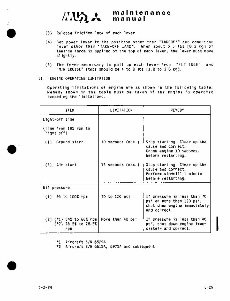
maintenancemanual
(3) Release friction lock of each lever.
(4) Set power lever to the position other than "TAKEOFF" and condition
lever other than "TAKE-OFF LAND". When about 0.5 Ibs (0.2 kg) of
tension force is applied on the top of each lever, the lever must move
slightly.
(5) The force necessary to pull up each lever from "FLT IDLE" and
"MIN CRUISE" stops should be 4 to 8 Ibs (1.8 to 3.6 kg).
11. ENGINE OPERATING LIMITATION
Operating limitations of engine are as shown in the following table.
Remedy shown in the table must be taken if the engine is operatedexceeding the limitations.
ITEM LIMITATION REMEDY
Light-off time
(Time from 10% rpm to
light off)
(1) Ground start 10 seconds (max.) Stop starting. Clear up the
cause and correct.
Crank engine 10 seconds.
before restarting.
(2) Air start 15 seconds (max.) Stop starting. Clear up the
cause and correct.
Perform windmill 1 minute
before restarting.
Oil pressure
(1) 96 to 100% rpm 70 to 120 psi If pressure is less than 70
psi or more than 120 psi,shut down engine immediatelyand correct.
(2) (*1) 64% to 66% rpm More than 40 psi If pressure is less than 40
(*2) 76.5% to 78.5% psi, shut down engine imme-
rpm diately and correct.
*1 Aircraft S/N 652SA
f2 Aircraft S/N 661SA, 697SA and subsequent
5-2-94 6-29

~-c;5 Itmaintenancem a a u a I
ITEM LIMITATION REMEDY
Ambient air temperature
(1) Start -40"C to ISA+30"C Do not start.
(2) Operating -54"C to ISA+30"C If in flight, search for the
place where the limitation
is met.
Turbine temperature
(1) During starts 1149"C Stop starting.(1 sec. max.) Overhaul engine.
(2) Takeoff power 923"C Reduce power. When temp.10" to 20"C is exceeded for
more than 30 sec. or more
than 200C is exceeded,record the max, temp. and
exceeding time on engine logbook and consult with
AiResearch Field Service.
(3) Maximum continuous 923"C See Takeoff power limitation
power
(4) Maximum cruise 905"C See Takeoff power limitation.
power
Engine speed
(1) Min. RPM 64% (fl) Correct with condition lever.
76.5% (f2)(2) Continuous maximum 99.5 to 100.5%rpm Correct with condition lever.
(3) 5 min. maximum 101% rpm Correct with condition lever.
(4) Absolute max. 106% rpm (*1) If exceeding 5 seconds,(5 sec.) 105% rpm (*2) overhaul engine.
Oil temperature
Type II oil Min. Clear up the cause and
Start -40"C correct.
Operating 55"C
Max.
Ground run
127"C
Takeoff
Climbing 127"C
(5 min. max.)Other operation
llO"C
fl Aircraft S/N 652SA
*2 Aircraft S/N 661SA, 697SA and subsequent
6-30 5-2-94

~is a a ii ~i Im a r;i ;t is i~o
ITEM
i
Totque
(1) pdwer c~ndition 1002 Reduce power with power leveic.
(2) Max. ebnt~huous 100% Same as above.
pdwer
(3) M~uc; cruise power 100% Same as above.
Fuel Pressure 15 to’ 90 psi If pressure is less than 15
psi or more than 90 psi, shut
down engine immediately and
correct.
oRgoelbjwr AS
RECEIVEDB~ 7~86-31
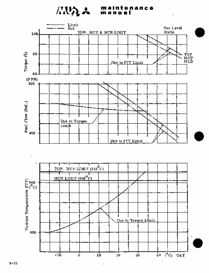
/I’~CCS Im a at a a a a a a
m a a a a I
LimitRef. Sea Level
too I TOP, MCP MCR LIMIT Static
80 TOPMCP
I I I I I I i I Du_e to ITT Limit ´•kY I I I1ICR
60
(P PH)500
I I IDue to TorqueT~j I ILimlt
400
Due to ITT Limit
TOP, MCP LIMIT (9230C)
MCR LIMIT (9050C900
(Oc)
Due to Toraue Limit
800
-Ib d Ib ´•b 3’0 iO (OC)OAT
´•6-32

maintenancemanual
12. TROUBLE SHOOTING OF ENGINE
GARRE~T Engine Maintenance Manual. IFor trouble shooting of engine, see
This is provided as an aid in locating the most probable cause of a mal-
function based on the symptoms it produces. Though primarily intended for
use by-maintenance personnel, it may aid a pilot or other operator of
the engine in writing-up more informative and meaningful "flight squawks",thereby reducing the time required by maintenance personnel in locating and
correcting the problem.
13. PROPELLER
13.1 GENERAL
Applicable to aircraft S/N 652SA
The propellers are Hartzell three-bladed propellers of the followingseries.
HC B 3TN 5 T1078 1I Series
(1) Type of hub includes HC-B3TN-5B, -50 and -5E.
(2~ Type of blades for 90 inch (2286 nnn) propeller is T1078HB-ll.
Applicable to aircraft S/N 661SA, 697SA and subsequent
The propellers are Hartzell four-bladed propellers of the followingseries.
HC B 4TN 5DL/LT10282 B (or HE) 5.3R Series
(1) Type of hub includes HC-B4TN-SDL.
(2) Type of blades for 98 inch (2489 mm) propeller is LT 10282
B-53R (or HB-5.3R).
Model designation used above is explained in example below.
(a) Symbols for propeller hub (Shown for 4-blade propeller)
HC B 4 T N 5 D L
LP,,peller rotational direction (CCW)Minor modification
i L-,- Specific design featuresL-- Flange with 8-9/16 in, bolts on circumference
LII Blade shank sizeof4 1/4 in. diameter
Number of bladesI
Basic designation__ Hartzell controllable pitch
(b) Symbols for propeller blade (Shown for 4-blade propeller)
3-31-90 6-33

c~r Itnl a i a t a a a a a a
manual
T 102 82 H B 5.3 R
LBlade tip is elliptic
i Diameter reduced 11 in.
I LI _,icins boots equipped
I IL_ Blade material is 7076-T61(SYMBOL H)2025-T6 (SYMBOL None)
Design basic number
I_
Basic diameter before reduction
Needle bearing is installed in blade shank
13.2 GENERAL DESCRIPTION
The propeller is constant speed, feathering and reversible; designed for the
GARRETT TPE-331 series engine. The total pitch range possible is from
full feather to reverse, but actual pitch range allowed to the aircraft is
about 920 as described later.
These propellers are designed to be controlled by a~governor installed on
the engine supplying engine oil through the propeller shaft. Governor oil
pressure (O to 400 psi) decreases pitch, including the reversing range;while counterweights attached to the blade clamps plus springs, located inside
the cylinder, increase pitch to the feathered position.
The propeller has spring-loaded centrifugal responsive latches (low pitch stop)which prevent feathering when the propeller is stationary. This is a typethat centrifugal force balances with spring force. When the propellerreaches high speed with condition lever in "TAXI" and power lever moving from
"FLIGHT IDLE" to "REVERSE" side, the propeller latch is disengaged.
An electric unfeathering pump is also provided to set feathered blades to
low-pitch.
13.3 REMOVAL OF PROPELLER
NOT E
Cover.engine air intake so that screws, etc.,
may not enter into engine through air intake.
(1) Open nacelle upper door.
(2) Remove cowling upper section.
(3) Remove spinner dome.
(4) Remove electric connector for propeller de-icing brush block.
(5) Remove brush block from attaching bracket (see Pig 6-47). When
removing, take care not to lose nuts and washers installed on the
lower section of the bracket.
Place a piece of tape or rubber band around the brush block, thus
retaining the brushes and avoiding their loss from the block.
(6) Remove brush block attaching bracket from engine.
6-34 3-31-90

dii 4 r h e e-.A ~i or i~ o
pin a a O ~ni I
(i) Setp~op´•PileP in featherea positioh.
’Set. Iib~er levi~r o’f dent~ir ped8stal t~ poisition.(b) Push "Pi~OP ~aPBA’riI’ER" o~erate puinp and ihove
blades slightly to Bide;
(c) hold pin of high i~itch stop. (SeeFig. 6-45)(d) Set lever to "TAi(EOFF" position and make "~ROP UNFEATHER’’
(8) RemoTieoil bdlton top; of propeller and taice out
oil transfe~ tube, turning slowly toprevent damage. (See Pig. 6~46)
NOTE
Handle oil. transfer tube -with
c8re to prevent damage or bend.
ORIGINAL
As Received ByAT P
Pig. 6-45 Remove prop, highpitch´• Pig. 6-46 Remooe screw and
stop and set prop. in I nut f.rom top of
feather´•position, propeller
(9) Loosen propeller attaching bolts from the back of~engine flange.
(See Fig. 6-48)
(10) After hanging.propelier with a’; sling (016-990!4 or equivalent), pull
out 8 bolts an~ remove propeller:from´•eng~ne.
(11) Remove 0-ring from engine flange.
6-35(36)

ORIGINAL maintenanceAs Received ByATP
manual
a-´•;s~::
Fig.6-47 Remove prop, de-icing Fig.6-48 Remove eight bolts
brush assembly from prop. flange
13.4 INSTALLATION OF PROPELLER
(1) Open nacell upper door and make sure that propeller de-icing brushblock is removed.
(2) Remove cover from propeller attaching flange, engine side and clean
up the flange.
(3) Lubricate a new O-ring with engine oil and put it in the flange.
(4) Make sure that propeller assembly has passed balance test andfunctional test.
(5) Remove spinner dome.
(6) Make sure propeller is in the feathered position. If no feathered
position, push up high pitch stop unit pin to set to feathered
position
(7) Hang propeller with a sling (016A-99074 or equivalent).
(8) Clean up propeller flange and check for damage.
(9) Install propeller so that dowel pin on engine flange may align with
hole on propeller flange.
(10) Install eight each of propeller attaching bolts (A-2047 or B-3339)and new washers (A-2048-2) from the rear of the propeller mountingflange of engine. Install washers under boltheads as shown in
Figure 6-48A.
NOTE
Replace with new propeller attaching bolts (A-2047or B-3339) and new washers (A-2048-2) when replacingpropellers.
3-31-90 6-37

maintenancemanual
Washer with no Washer with countersink
contersink /The countersink side
the washer must face t
bolthead. Do not use washer
not interfere wi:") withameter .sharp edge at insiderner radius shal
Round side
Propeller attaching bolt
Fig.6-48A
a. When attaching bolt A-2047 is used. Torque to 125 ft-lbs.
NOTE
Apply torque in sequence as shown in Figures 6-48B and
6-48C.
b. When attaching bolt B-3339 is used.
(a) Apply lubricant (petrolated graphite MIL-T-5544 or TRW Hartzell
lubricating oil A-3338-1) on bolt thread and washer surface beforeinstallation.
(b) Ensure the mounting flange surfaces of propeller and engine are inclose contact before tightening attaching bolts.
(c) Tighten bolts as follows.
(i) Temporarily tighten eight bolts.
(ii) Torque in the order as shown in Figure 6-48B to 40 ft-lbs, and
then in the same order to 80 ft-lbs.
(iii) Torque in the order as shown in Figure 6-48(3 to 100 thru 105 ft-
Ibs.
3-31-90 6-37-1
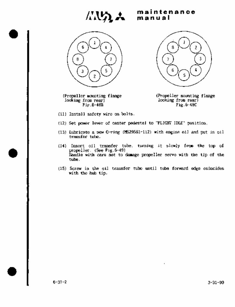
c~rmaintenancemanual
ooo00 00ooo
(Propeller mounting flange (Propeller mounting flangelooking from rear) looking from rear)
Fig.6-48B Fig.6-48C
(11) Install safety wire on bolts~
(12) Set power lever of center pedestal to "FLIGIIT IDLE" position.
(13) Lubricate a new O-ring (MS29561-112) with engine oil and put in oil
transfer tube.
(14) Insert oil transfer tube, turning it slowly from the top of
propeller. (See Fig.6-49)Handle with care not to damage propeller servo with the tip of the
tube.
(15) Screw in the oil transfer tube until tube forward edge coincideswith the hub tip.
6-37-2 3-31-90
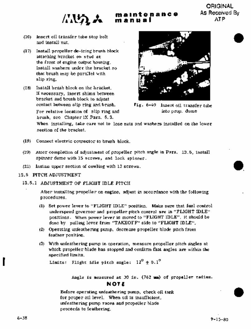
ORIGINAL
It maintenance As Received Bymanual AT P
(16) Insert oil transfer tube stop bolt
and install nut.
(17) Install propeller de-icing brush block
attaching bracket on stud at
the front of engine output housing.Install washers under the bracket so ~7that brush may be parallel with
slip ring.
(18) Install brush block on the bracket.
If necessary, insert shims between
bracket and brush block to adjustcontact between slip ring and brush. Fig. 6-49 Insert oil transfer tube
For relative location of slip ring and into prop. dome
brush, see Chapter DI Para. 5. 3.
When installing, take care not to lose nuts and washers installed on the lower
section of the bracket.
(19) Connect electrid connector to brush block.
(20) Arr;er completion of adjustment of propeller pitch angle in Para. 13.5, install
spinner dome with 15 screws, and lock spinner.
(21) ZnstaLr upper section of cowling with 13 screws,a
13.5 PITCH ADJUSTMENT
13.5.1 ADJUSTMENT OF FLIGHT IDLE PITCH
After installing propeller on engine, adjust in accordance with the followingprocedures.
(1) Set power lever to "FLIGHT IDLE" position. Make sure that fuel control
underspeed governor and propeller pitch control are in "FLIGHT IDLE"
positions. When power lever is moved to "FLIGHT IDLE", it should be
done by pulling lever from "TAKEOFF" side to "FLIGHT IDLE"
(2) Operating unfeathering pump, decrease propeller blade pitch from
feather position.
(3) With unfeathering pump in operation, measure propeller pitch angles at
which propeller blade has stopped and confirm ihat angles are within the
specified limits.
Limits: Flight idle pitch angle: 120 f 0.I"
Angle is measured at 30 in. (762 mm) of propeller radius.
NOT L
Before operating unfeathering pump, check oil tank
for proper oil level. When oil is insufficient,
unfeathering pump races and propeller blade
proceeds to feathering.
6-38 9-15-80
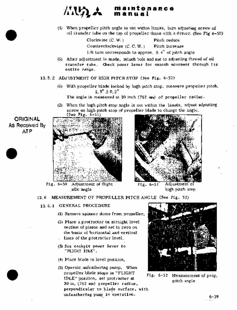
IPO PIIPBIBii d i~ I B
(4) ~n BrbpeliBj: pitch angle is riot within limits, tumadjusting scri~iv df
oil eub’e on the top of pjrapeiler dome wieh B.drivei´•, (See Fig ’6-5~0)
(’C. W; Pitch reduce
i=ounterclockwise (i=i C. W. Pitch increase
1/6 turn corresponds to appjrox. 0. 40 of pitch angle
(5) After adjustinBnt i~ made, attach j~olt and nut to adjusting thread of oil
trhnsfei tube; ’Ctieck lever for smooth movPment: through its
entire range~
13.5. 2 OF PITCH S~CjP (See Fig´•. 6-52)
(1) pro]i~eller bladle.iocked by high pitch stop, measure prdpeller pitch.2, 5" 0, 2"
The angle is measured at 30 inch (762 rmn) of propeller radius.
i2)~ When the high pitch stop arigle is not within the limits, adjust adjustingscrew on high pitch stop of propeller blade to change the angle:
~(See Fig, 6151)ORIGINAL e.
As Received ByAT P
I
r.
Fig. 6-50 Adjustment of flight Fig. 6-51’ Adj ustment of
idle angle high pitch’ stop
13, 6´• MEASUREMENT OIF’PROPELLER PITCH ANGLE (See Fig, 52)
1´•3. 6. 1 GENERAL PROCEDURE
(1) Remove spinnerdome from- propeller.
(2) Place a protractor on straight level
section of piston and set to zero on
the basis of horizontal and vertical
lines -of the protractor level,
(3)_Set coCkpit power lever to
"FLIGHT IDLE".
(4) glace blade in level position,
(5) Opeyate~unfeatheMng pump, When
propeller plade~ stops in !’FLIGIj[TFig, 6-52 Measurement of prop.
IDLE" pos~it´•ion, set protractor at
.30 in. (762 mm): propellei~ radius,pitch angle
perpendiculair ´•tb:blade surface, with,
unfeathering Ipump in operation.6-39

C~ ~t m a c ii t a a a a a a
n~ a~ a a)
The jprotractor reading indicates "FLIGHT IDLE" pitch angle."REVERSE", "FEATHER" and "START" pitch angles can be
measured ih the same way.
13. 6. 2 MEASUREMENT OF PITCH WITH REFERENCE TO FEATHERING
PITCH ANGLE
(1) Set propeller in "FEATHER" position. Place protractor at 30 in. (762mm)propeller radius, perpetidicular to blade surface and set to zero on the basis
of horizontal and vertical lines of the protractor level.
(2) When blade stops in "FLIGHT IDLE" position, note the protractor reading."FLIGHT IDLE" pitch angle is obtained by deducting the protractor readingfrom feather pitch angle.
13.7 REPAIRING CRITTERTA OF BLADES
13.7.1 SCOPE OF REPAIR
Nicks located within a quarter of length of blades from the center shall
not be repaired, but the blade shall be replaced;
13. 7. 2 REPAIRING PROCEDURES
(1) Nicks on leading edge or trailing edge of blades (See Fig. 6-53)
Radius
3 in. min.
(76. 2 mm)FACE
SE CTION
To be smooth becauseTo be smooth
crack starts here.
This dimension must meet the
requirement of Para. 13.7.3 (min. width)
Fig. 6-53
(2) Damages on blade surface (See Fig. 6-´•54)
To be smooth
r~5f
D~10 f
I I T:This dimension inust
meet the requirementof Para. 13.7.3.
f I j I (min. thickness)
Fig. 6-54
6-40
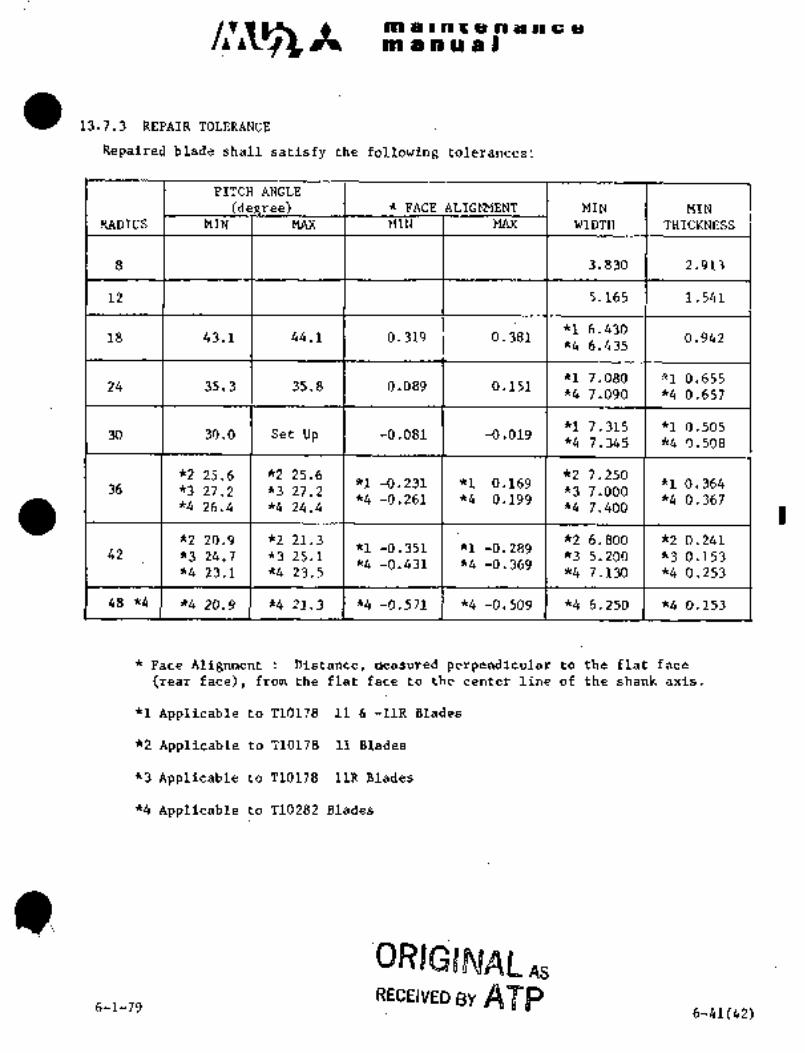
m a~n a a Ion a Inr a n an c a
13.7.3 REPAIR TOLERANCE
Repaired bladeshall satisfy the following tolerances:
PITCH ANGLE
(de eel FACE ALIGMMENT MIN MIN
RADIUS MIN MAX )IIN MAX WIDTII THICKNESS
8 3.830 2.913
12 5.165 1.541
*I 6.43018 43;1 44.1 0.319 0.381 0.942
*4 6.435
*1 7.080 "1 0.65524 35.3 35.8 0.089 0.151
*4 7.090 *4 0.657
*1 7.315 ~1 0.50530 30.0 Set Up -0.081 ´•-0.0 19
*4 7.345 ~4 0.508
~225.6 *2 25.6 *2 7.250*1 -0.231 *1 0.169 "1 0.364
36 *3 27.2 *3 27.2 *3 7.000~4 -0.261 *4 0.199 "4 0.367
~4 26.4 *4 24.4 k4 7.400
5(2’ 20.9 *2 21.3 *2 6.800 *2 0.241kl -0.351 *1 -0.28942 *3 24.7 *3 25.1 *3 5.200 *3 0.153*4 -0.431 *4 -0.369
*4 23.1 *4 23.5 *4 7.130 *4 0.’253
48 *4 k4 20.9 *4 21.3 *4 "4 -0.509 "4 6.250 k4 0.153
Face Alignment Distance, measured perpendicular to the flat face
(rear face), from the flat face to the center line’of the shank axis.
kl Applicable to TlOli8´• 11 -ilR Blades
*2 Applicable to T10178 11 Blades
~3 Applicable to T10178 11R Blades
*4 Applicable to T10282 Blades
QRIGBMAIL.6-1-79
RECEIVED gy APP6-41(42)

ia a’n ii d Im a I at O a b‘ii a
13. 7.4 PROCESSING AF’I’ER REPAIR
If a small area of-bladesurface is repaired, the area shall be touched up with
chemical film and refinished with a coating of the following paint;Neogosei #200 (Shinto Toryo KK)or equivalent epoxy resln painta 13. 8 TROUBLE BHOOTING FOK PRDPELLER~
Trouble Probable Cause Remedy’
RPM fails to Start lock blhde Adjust start’lock,increase gngle too high,normally at
starting or
will reduce
dur running
RPRI change in Exce s s ive .friction’ in ´•’See "Excessive fri~tion in hub
both directions hub mechanism. mechanism".
is sluggish
Excessive a; Pilot t~be has ´•slipped Push´•down pilot tube ~and measure
friction in hub out sli´•ghtly and is height from -top of hub spider to
mechanism rubbing hard against top:end of pilot tube. Should ´•beend of hole in blade. 3 :3/4´•´•in; (95.3 mm).
b. Damage to split Replace be8ring.bearing
c. Excessive friction of Check part$ individually. If tight-piston assembly. ness is encountered~ in sliding
parts, ´•increase clearances slightl
a oil extemaiig ia moving
6-43

ma~atenancepa a a a a I
Trouble Probable Cause Reinedy
RPM is not adequate a. Inadequate adjustment See "Excessive friction in hub
of propeller governor, i mechanism" in this chart.
b. Inadequate adjustment See "Excessive friction in
of underspeed i~ub mechanism:
governor.
Failure to feather a. Governor control Provide sufficient travel in
does not provide governor control. Governor
enough travel to must drain oil out of propellerallow governor to during feathering.move from feather to
high pitch stop.b. Excessive friction. See "Excessive friction in hub
mechanism" in this chart.
c. High pitch stop pin Check for burrs onpins. Check
fails toslide out at for stiffness of spring. If
feathering rpm. I’propeller feathers at high rpm
but fails to.feather at low rpm,too-stiff spring is indicated.
Red~ce length of spring by one
or two coils.
d. Weak or droken Replace spring.
feathering spring.
Surging a. Air trapped in pro- Provision should be incorporated(When governor peller actuating in engine to allow trapped air to
control is changed piston or in engine escape ´•from system during one
rapidly or rough shaft. half of the pitch change cycle.air is encountered. I I Exercise propeller by changing
pitch or feathering before each
flight.b. Governor pressure A.djust governor relief pressure
too low. .I so that rate of pitch change is
the same in both directions.
c. Excessive friction. See "Excessive friction in
hub mechanism"
d. Governor lacks suf- Change or adjust speeder spring.ficient dampeliing. This gives governor more
stability, but makes pitch control
more sensitiv~, which may in turn
require re-rigging or control to
offset~higher spring rate.
Changing to stiffer speeder springshould be done only after all other
factors have been checked and
corrected;
‘til-~i4

T ~il ,IFI LII ii iC O.:i.´• :.i
pDI 3i~n U ail B
i´• a.,,... ...:´•i
Oit 1~.KB*ge Fai~lty O-ring s’eals as Dlshs~eirible and O;Mrigs ana
fblldw~ i ’tlieji s’e811 iEeplaceC)-riligs if de~fective, Replace
g~ Propeller shaftcylinder if is scrati~hed or
nicke$’ili area where ’Or ring slides.
b, Cylinder USe gasket compound’on cylinderthrea%ds when replacing, Peen down
c. Pistonraised places caused by tightening of
d, Pilot tube cylinder with bar,ii
Grease leakage a. ~Grease leaks past Loosen clamp bolts and replace(Only sdurc~e of clamp seal gaskets. gaskets. Standard thickness of
grease leakage gasket is 0.’05 in., but 0, 06 in.
is blade gaskets are available in case 0, 05 in.
bearings, gasiiets a~e not compressed suffi-
ciently to hold,
b, Grease leaks from Iliscribe blade with ink or pencil to
between biade and assure correct; blade angle on
clamp,. reassembly, and~remove blade and
clamp. Add gasitet compound in
radius of blade butt, Replace blade
and clamp,
13.9 DISASSEMBLY´• OF PROPELLER
(1) -Remove the spinnerdome. Mount the propeller ona table (016A-99034or equivalent)~with 4 bolts.
(2j Identify hub spider and propeller blades by numberwith’grease pencilfor ease of pitch angle setting.
(3) Remove ~lower safety screw of link arm from pis’ton unit.
(4) Withdraw link pin unit and disconnect link arm from piston unit.
(5) Remove’hub clampsthat~hold the de-icer boots leadstrap.
(6) Remove outer blade clamp.boltand nut, and inner blade clamp socket
screw,
(7)-.Remove blade~clamp and gasket.
Remove blades from hub spider.
(9) Remove b~earing retention ring and split:bearing ball and ball.spacer:
(10) Remove ild ´•rir;g..
(11) Remove flexlock nut.
(12) Remove "O’) ri,B aod aus; seal.
6-45(46 thru 50)
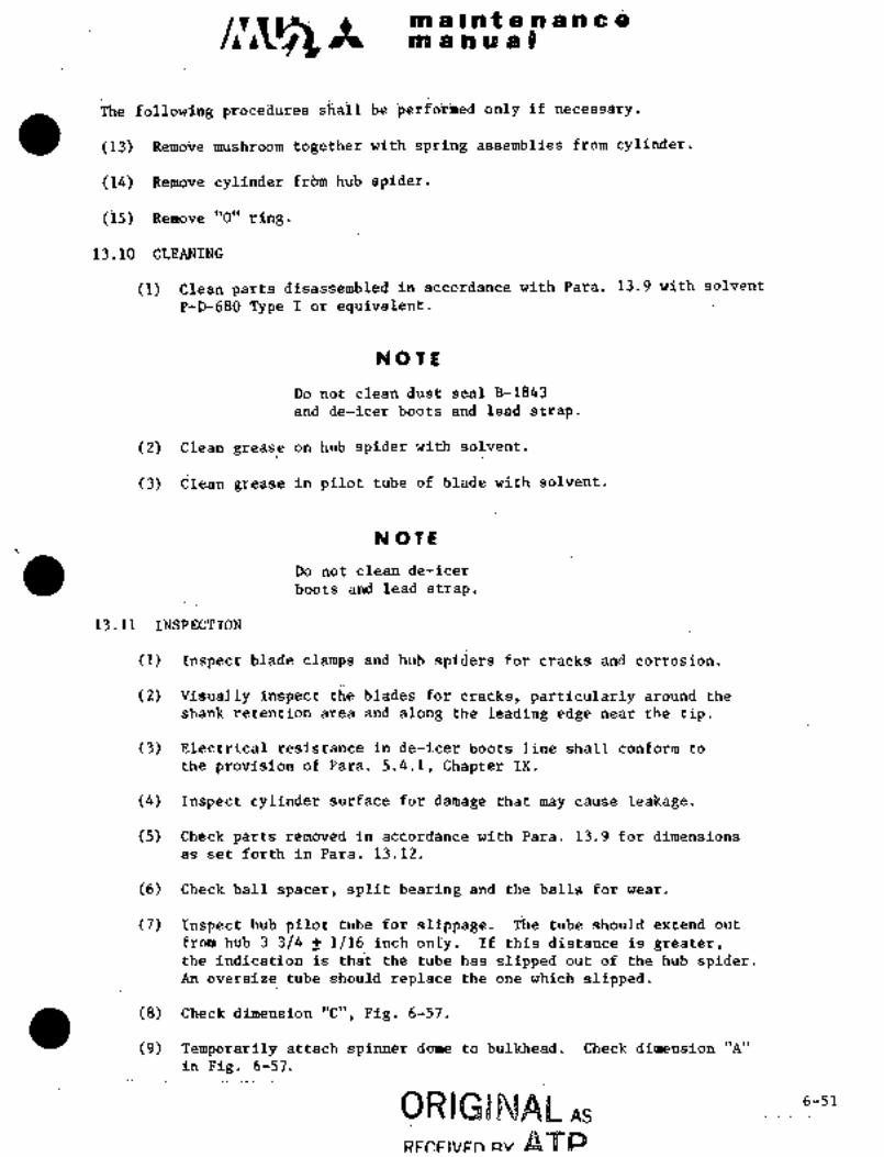
is~ i~ u ~i I
The f~ii:d’triiig proceiiur~ ~iiail b~e’pelfoiined olily if ne~esSgry.
(13) with spring assemblies from cylinder.
(14) Remove ~cyliad;er f~bm hub spider.
(i5) Remoire´• ’’0" ring.
13.10 %LEANING
(1) Clean partb disassembled In accordance with Para. 13.9 bith solvent
P~D;680Type I or equivalent.
NOTe
Do not ciean dust seal B-1843
and de-icer bbots strap.
(2) Clean grease on hub spider with solvent’.
(3) Clean grease’ in pilot tube of blade with’solvent.
NOTE
Donotclean de-icer
boots and lead strap.
13.11 INSPECTION
(1) Inspect blade clampsand hubspiders for cracks and corrosion.
(2) Visually inspect the bladesfor cracks, particularly around the
Shank retention area and along the leading edge near the tip.
(3) Electrical resistance in de-icer boots line shall conform to
the provisidn of Para.5.4.1, Chapter IX.
(4) Inspect.cylinder: surface for damage that may cause: leakage.
(5) Check parts removed in accordance with Para.. 13.´•9 for dimensions
as set forth in Para. 13.12.
(6) Check ball.Spacer, split~´•bearing and the balls for wear´•.
(7) Inspect hub pilot, tube for~ slippage. The tube should~ extend..out
from hub 3´•3/4 f´• 1/16.inch only’.~]If this distanceis greater,the Indication. is that~-the tube has:slipped out of the hub. spider.An oversize tub;? should repldce fhe one which ´•slipped;
(8~’:’Check dimension "C", Pig. 6-57.
(9) Pemporiirile attach spinner dome to bulkhead. Check dimension "A"
in Pig. 6-57.
As.6-51
RF~FIVFn Rv

C~k ~i a I at a a a a a
an a a a Bi
Terminal board for~de-icing wire
.r
~CA~ter spinner installa-
tion check for a minimum
clearance of 0.12 in.
(3 mm) between the spinnerRive nut
I edge and the propeller in
I all positions; re-form
(spinner if necessary.
0)(0
AILI ’B
A 0.12 f 0.03 in. (3.05 f 0.76 rmn)´•~J ~E1~(E( B 3.25 f 0.01 in. (82,55f 0.25 n~R)’Hp,Oc
C 0.47 1-0.03 in. (11.94 f 0.76 mm)
wk oi
d~ip ´•k
wk Q, Fig. 6-56
o
13.12 TOLERANCE
For overhaul tolerances, see Hartzell Manual No. 118.
6-52
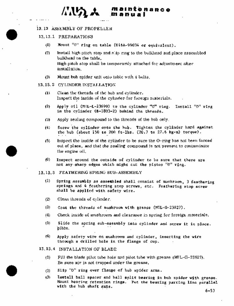
´•4 ~i os ~ce C
iS, 13 ASSEMBhY OF
19, 13. 1 PREPARATIONS
(1) Mount "0" ring on table (016A-99~34´•or epi~ivalent).
(i) Install high pitch stop and slip rin~ td the bulkhead and place asseri~isledthe t~bl’ei
High pitch stop shall´•b~e temporarily a~tached for adjustment after
install‘ati~n.
(3) PJIount hub spid8~ ~uiit orito table with 4 bblts.
13.13.i CYLINDER INSTALLATION
(1) Clean tl?ethreads df the hub and cylinder.Inspedt the inside of the cylinder´•fdr foreign materials.
(2) A~ply oil (MIL-L-2369.9) to the cylinder "O"ring. Install "O’’ ringin the cylinder (B-1803-2) behind the threads.
(3) Apply ´•sealing conipound.to the threads~ of the hub.only.
(4) Screw the cylinder onto the hub. Tighten the cylinder hard againstthe hub(about 150 to 200 ft-lbs. (20.7 to27.6 kg-m): torque).
(5) Inspect the inside of the cylinder to be sure the O-ring has not been forced
out of place, and that thesealing compound is not present to contaminate
the engine oil.
(6) Inspectaround the outside of cylinder to be sure that there are
not any sharp edges which might cut the piston 10" ring.
13’. 13. 3 FEATHERINC SPRING SUB-ASSEMBLY
(1) -Spring ´•assembly ´•as asseinbled shall consist of- mushroom, 3 featheringsprings and 4feathering stop screws, etc. FPathering stop screw
shal~.be applied with safety wire.
(2) Clean threads of cylinder.
(3) Coat the threads of mushroom with grease (MIL-G-23827).
(4) Check inside’of’ mushroom and clearance in spring for foreign materials.
(5) Slide the~ spring sub-assembly irlto, cylinder-´•and´• screw it in place.’is~ace.
(6) Apple safety’wire on.mush’rboni~gnd´• cllin~dei:, inserting the wire
throug;h a drilled:holBin the flange of cup;
13. i. 4 .INSTALLATION:OF BLADE
(1) Fill the blade pilot tube hole’ and pilot tube~with-grease (MIL-G-23827).~Be sure air is not trapped under the grease.
(2) .’Slip "O" ring over flange of hub´• spider arms.
(3) Instali:dail:spacer and ball split bearing- in hub spider with grease;Mount.bearing ret’ention rings. Put the bearing parting line parallelwith the hub shaft axis.
6-53

´•t´• pjl 8 In t 8 a a ii am a ~i a a s
(4) E’ill split bearing with grease.
(5) install blade on hub pilot tube. Sprend sealing compound ground the bladeshanic in the shoulder radius.
Do not change original comhination of blades and hub spider.
(6) Install the correct matching clamp. Slip the clamp gaskets between
the clamps at the parting line.
This procedure will locate the inner bearing race parting line at
right angles with the blade clamp parting line.
The installation shall meet the requirement in Para. 13.14 (6).
NOTE
clamp gasket
Clamp
Take care not to place clamp gasketin these positions.
(7) Tighten the outer blade clamp bolts and nuts, and inner blade clamp socket
screw.
Outer clamp bolts 60~-65 ft-lbs (8.3"9.0 kg-m)Inner clamp socket screw 40 ft-lbs. (5´•5 kg-m)
(8) "1 Hold de-icer boots lead strap in position with hub clamp. Fas ten
with screw.
~2 Secure wire leads with tie straps (MS18034-6).
(9) Connect de-icer boots wire harness to terminal strip. Support with
lead clip.
(10) Inspect blade for smooth rotation by turning blades by hand. Check
bQarlng for friction.
13.13.5 PISTON ASSEMBLY
(1) Install O-ring in the second groove and dust seal in the first groove
of the piston unit. Soak seal and.O-ring with. engine oil (MIL-L-23699).
(2) Carefully inspect inside of cylinder for foreign materials. Slide
the piston onto the cylinder.
(3) Install the link arms in the piston.. .Insert all link pin units.
(4) Install safety screw and safety wire.
*1 Aircraft S/N 652SA
*2 Aircraft S/N 661SA, 697SA and subsequent
6-54

ma~ntenancemanual
(5) Soak "O" ring in engine oil (MIL-L-23699). Install "O" ring in
the cylinder.
(6) Install flexlock nut on end of pilot tube. Torque to 120 ft-lbs.
(16.6 kg-m).
13.14 BLADE SETTING
(1) Blade end play in peripheral direction shall not exceed 1/16 in; (1.6 mm;.
(2) Fore and aft blade movement at tip shall not exceed 0.1 in. (2.5´• mm)
(3) Blade track of blades shall not exceed f 1/16 in. (f 1.6 mm) when
measured at 4 in. (101~6 mm) point from tip with blades in flat
pitch position.
(4) No blade slip shall occur ~between clamp and blade when blade is torguedto 167 ft-lbs. (23’kg-m) with respect to‘pitch control axis.
(5) Counterweight angle should be located within2" beyond the propelleraxis when in reverse pitch. (See Fig. 6-57)
Counterweight angle’ Countenveight
Reverse
5~
dFig. 6-57
6-55

m a Int a a 8 a a a
manual
13.15 PROPELLER BALANCING PROCEDURE
13.15.1 GENERAL DESCRIPTION
Dynamic balancing of the propeller should be performed to prevent possibleengine and prop hub damage due to a heavy blade. An unbalanced propeller
may cause a harmonic vibration resulting in engine component damage and
flight and passenger compartment noise and discomfort. Propeller balancingshould be performed when deemed necessary; after routine prop maintenance,overhaul, propeller replacement of flight squawk by the ´•pilot.
13.15.2 SPECIAL TOOLS AND/OR EQUIPMENT
Items 1 through 2 are manufactured by Spectral Dynamics Corp. of San Diego;items 4 and 5 are ma‘nufactured by IRD Mechanalysis, Inc., Columbus, Ohio;and items 3 and 6 are manufactured by Mitsubishi Aircraft Int’l.
MODEL NO. ITEM NOMENCLATURE
1. DS119B Trim Balance Analyzer
2. M 801 Velocity transducer
3. MTS 700A or equivalent# Mounting Bracket
OR
4. 330 Vibration Analysis/DynamicBalancing
5. 544 T-321-1 Vibration Pickup
6. MTS 700 or equivalent" Mount Bracket
*MFG by MAI
13.15.3 PRELIMINARY
Check to be sure the following have been complied with before balancing propeller.
1. Prop has been properly greased.
2. Aircraft has flown or run at least thirty minutes since lubrication.
3. Start locks are set at 2.5 f 0.10
4. Flight idle blade angles are 12.0 f 0.10
5. Propeller spinner properly installed and clocked.
Any discrepancy´•in the abnve shall be corrected prior to balancing the
propeller(s).
6-569-15-80

A ~rii a:i nt e n a aiii a a a a s
13.15.4 SET UP
h: General
Gain access to top engine gear ~ase by raising upperenginenacelle door and securing support rod in open positi~n-.
NOTE
Sec~ire’’ or tighten~door latches
to avoid loss during engine run.
(2) Remove.cl~´•inp s.ecuring prop .de-ice 8nd’ syrichrophaser ´•i~riringharness from bossed area on engine gear case and move to one side.
(3) Install mounting bracket to bossed area of gear case, Fig.‘ 6-58, and
install velocitytransducer (M80) or vibration-pickup (544 T-321-1)on mounti;lg bracket.
(8) Move and;/or remove the following as required:
(1) Disconnect fuel pressure transmitter electrical connector.
(2) Disconnect pressure line´•between fuel control assembly and
fuel pressuretransmitterat transmitter.
(3) Remove safety wire and 4 bolts attaching fuel pressure trans-
(4) Plug pressure line and port.
mitter’assembly; remove transmitter from aircraft.
(4) Connect one coax cable end to velocity transducer or vibration
pickup and the other end to the analyzer. It~ is suggested to
route coaxas shownin.Fig. 6-59.
B. SetTup Using. Spectral Dynamics Equipment
(1) Cdnnett power cord (115 ~VAC) to trim balance analyzer and t~o power
source. Turn analyzer to test and allow stabilization time. Check
display on trim b’alance analyzer to ensure proper calibration. The
following readings should beobserved: 5.0 mils displacement,6,000rpm-, 1800 phase (if applicable), a tolerance of f‘l% of the
values´•is acceptablefor prop balance..
(2) The following settings and/or adjus’tments should be ~made before
beginning the prop balance´•,check.
SW.ITCH ´•-’´•,tl ,POSIT~ON/SETTING
Display Range 10
Pickup-Ampl Display: :VEL D
Mode 00 Automatic:
Filter IN
Input Selector As Required
6-57

manualmi ri i ii t e a a ii a e
1AN526-lOW6 sc;-ew, I-BO:;S with Hell Coil (TS’p 3 ptaces)
(Typ 3 places)2.15
Z TQ to 5 in-lbs
0~L’c~1
Bracke~ ’L’iY\´•. O
View A-A
Viiir´•. Picli-U1> Bracket
1 clarify
r7 I I ~Z Prop. Shaft (Ref.)
Bracket7-
(View looking aft from’front of engine)
FFg. 6-58 Installation -Bracket-Vib Pick-Up
6-58

irC re I ilt ~i, a ii is ;c ~isis i a a a I
Coax
Pick~ Up
Analyzer I on. Work Bench
Fig:. -6-59
HEIGHTS
61 00d
Figi 6-60 Balance~ Weight Location
6-59

/iir~ ´•t no a n a
ni a I:~i t.;e ii a h.e 8
During Engine Run
Adjust the rpm speed manually (smaller mode knob) to indicate
1,600 f 1 rpm.
NOT L
It may be necessary to
adjust the rpm settingduring each engine run.
Allow amplitude to settle, depress "Display Hold/Update" switch
to lock the "mil displacement" indication.
C. Set-up Using IRD Equipment
(1) Turn power switch to AC or BATT positioh as required; if AC, connect
to power source prior to turning AC ON. Turn "Amplitude Range"select switch to TEST, allow needle to settle, check amplitude"test" indication.
(2) The following settings and/or adjustments should be made before
beginning prop balance check.
SWITCH POSITIONISETTING
Amplitude Range 10
DISP VEL DISP M~LS
Frequency Select 500 5 K CPM
Filter Tuning Dial 1,590
Input Select L or R as required
13.15.5 BALANCING PROCEDURE
A. If the propeller ~ias been balanced before or has balance weightsinstalled, a preliminary run may be required; refer to Pig. 6-60.
(1) Start engine and allow time’for warm up.
(2) Accelerate engine to 100% rpm with Eiropeller on.start locks.
(3) Allow engine to stabilize, then observe and record displacementreading.
(4) Should the reading be 0.5 mils or less, no further action is
required; proceed to Paragraph "C"
B. Perform the following displacement checks for each engine run. All runs
to be at 100% rpm and propeller blades on start locks. For placement:of weights (slugs), see Fig. 6-60. Number prop blades’, i, 2, etc.
(1) Run No. 1
Remove all dynamic balance weights (slugs) from the propeller.Run engine and record the value "mil" displacement.
6-60

maintenancemanual
(2) Run No.2
Install 3 weights to blade i, run the engine and record the
value "mil" displacement.
(3) Run No.3
Remove weights from blade 1 and install on blade 2, run engineand record the value "mil" displacement.
(4) Run No.4
Remove weights from blade 2 and install on blade 3, run engineand record the value "mil" displacement.
(5) Run No.5 (4 blade propeller only)
Remove weights from blade 3 and install on blade 4, run engineand record the value "mil" displacement.
(6) Subtract the "Disp Mil" value of R1 from each "Disp Mil" value
of the additional runs to find the unbalance of each blade and
record in the "Balance Data" column.
(7) Determine the heaviest blade by noting the highest displacementvalue as found in (6;) above.
(8) Subtract each light blade from the heaviest blade and record in
the "Disp Value" column.
(9) Find the "Disp Value," determined in (8) above, in column A of
the Displacement Balance Chart under the heading "DISP MILS" to
determine the quantity of weights required for each blade.
(10) Install the required number of weights on the appropriateblade(s). Run the engine and record the mil displacement in the
"DISP MILS" column for the next run; also record the weightquantity per blade in the space provided.
(11) A maximum mil displacement of 1.0 mil is acceptable, but 0.5 mil
or less is preferred. If the recorded value is greater than 1.0
mil, find the "DISP VALUE" in column B of Displacement Balance
Chart to find the adjusted quantity of weights required perblade, and record inthe space provided for the next run.
Perform next run and record DISP MILS.
N~TE
i. No more than four stacks of eleven weights perblade should be used.
ii. A maximum of three weights should be installed on
the de-icer wiring clamp ton the back side of the
blade).
3-31-90 6-61

c~rhmaintenancemanual
iii. A minimum of three threads engaging with clampthread is necessary for screw length to install
balance weight to the clampiv. If dynamic balance cannot be adjusted by balance
weight installed on clamp, balance weight may be
installed on bulkhead by HARTZELL S/I No.148A.
(12) All propellers that have been dynamically balanced should be
identified with special Decal No. A-2803k installed on the
propeller cylinder. The presence of this decal will alert
propeller repair station personnel that the existing balance
weight configuration may not be correct for static balance
purposes
CAUTIONTHIS PROPELLER HAS BEENDYNAMICALLY BALANCED.
Location of Static Balance WeightsMay Have Been Altered.
A-2803
Decal No. A-2803
C. Restore aircraft to original configuration.
(1) Disconnect coax cable from velocity transducer (M80) or vibration
pickup (544 T-321-1) and test unit. Remove velocity transducer or
vibration pickup and mounting bracket.
(2) Install fuel pressure transmitter,if removed.
(a) Remove pressure line and port plugs.(b) Position fuel pressure transmitter in place, attach with
bolts, tighten to proper torque value and safety wire.
(c) Connect pressure line to transmitter and tighten to proper
torque value.
(d) Connect electrical connector and safety wire.
(e) Move wire harness into position, secure with clamp and
safety wire.
(f) Secure and/or remove door support rod, close upper enginenacelle door and latch.
(3) Reference the spinner to a blade and remove spinner.
(4) Tighten weight attaching screws and safety wire.
(5) Install spinner per blade reference, clock (center) spinner and
torque attaching screws to correct valu.
6-62 3-31-90

manualmaintenance
Sarbple Prppeller Balance
DISP WEIGHT 9UANTITYRUN DISP BALANCENO MILS DATA VALUE BLADE NO
(HEAYY 1 2 3 4
O O O O
R2 1 -09 1 9 -(-as)= 2.8 j 3 1 O O O
R3 6~2 j1.9 -[-/.3)=3.21 O 1 3 O O
R4 1 9~4 1 ,7.5 /.9 1/.9 -/.9 =0.0 1 O I O 3 1 O
R5 g~ j ,75 i´•b j 1.9 /.b 0.3 j G j O j O i 3
R6 0´•55
R7j:: :’:.:I:::::i´•J:: ´•´•:-::i::.:j-:´•: i::l
i:
3-31-90 s-sz-l/s-sz-2
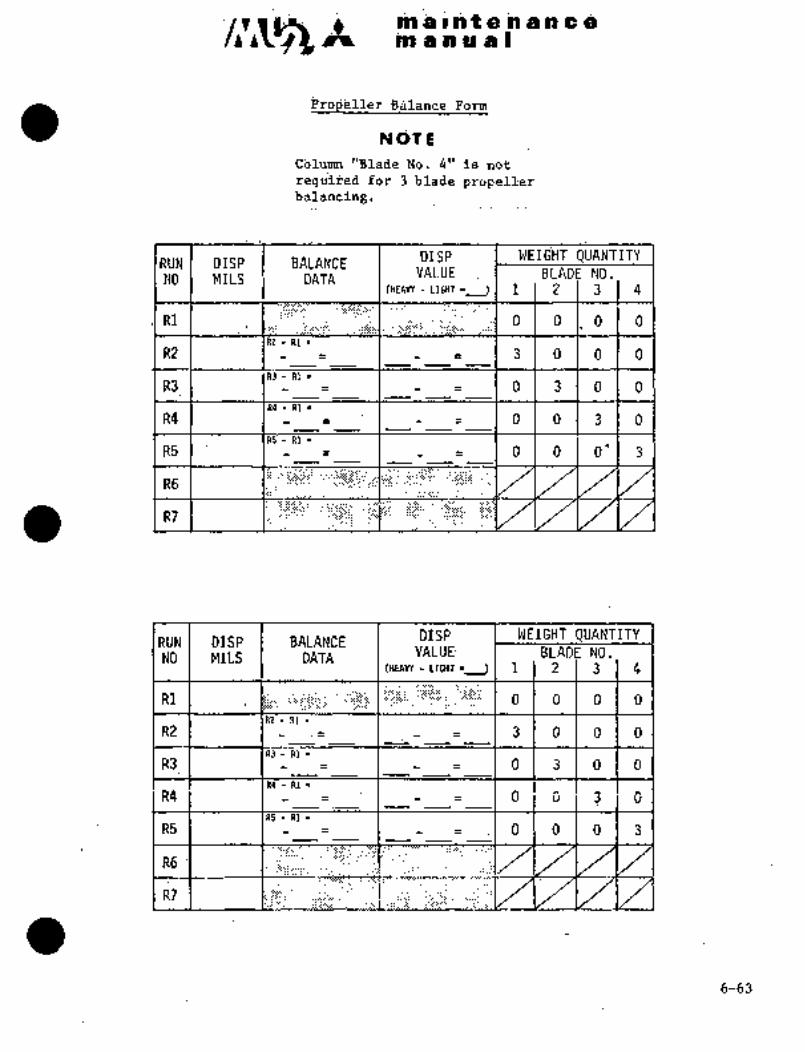
i.
itlll iihi :iiii a~e a
rCI iii ~i s
~brm
koli
Cblu´•I~ "Blafa~ ~ol .4" 19 not~
3
RUN BA~ANCE DISP 1 WEI6HT QUANTTTY
NOI MilS DATAVALU~ NO.
(H~AVY ilGHi i 1 2 3 4
R1 o I O.l.o o
R2 I ´•1 1 3 O. i O O
R3-R1´•R3 O 3 O O
R4. R1´•
R4 O O 3 O
R5- R1´•
R5 1 I I r I O O 0’ 1 ´•3
R6
RUN ´•I DISP -´•I BALANCE DISP I I WEIGHT QUANTITYVALUE BLADE NO.NO´• MILS I DATA
(HEAW LIGHT~ 4
R1 I: O O O O
R21: I I 1 3 1 O j O I O
R3 I I I I o’l 3 1 O 1 O
R4 i i´•‘- ~´•´•i iQ i ´•01 3 i- ’G
R5 I .-i .I 0 I olo~13
R6
R7
6-63

c~sn at an a a Im a I h t 8 ni a a a i,
DISPLA6EMENT DALANCE CHART
COLUMN A COLUMN 5
DISP MTLS WT QTY DISP MILS
O to 0.30 0.0 O to 0.30
0.35 to 0.60 0.5 0.35 to 0.65
0.65 to 0.90 1.0 0.70 to 1.00
0.95 to 1.20 1.5 1.05 to 1.35
1.25 to 1.50 2.0 1.40 to 1.70
1.55 to 1.80 2.5 1.75 to 2.00
1;85 to 2.10 3.0 2.05 to 2.40
2.15 to 2.45 1 3.5 1 2.45 to 2.70
2.50 to 2.75 4;0 1 2.75 to 3.05
2.80 to 3.05 4.5 1 3. 10 to 3.40
3.10 to 3.35 5.0 3.45 to 3.75
3.40 to 3.70. 5.5 1 3.80 to 4.10
3.75 to 3.95 1 6.0 4.15 to 4.50
4.00 to 4.30 6.5 4.55 to 4.80
4.35 to 4.65 7.0 4.85 to 5.20
4.70 to 4.95 7.5 1 5.25 to 5.55
5.00 to 5.30’- 1 .8.0 5.60 to 5.90
5.35 to 5.60 1 8.5 1-- 5.95 to 6.25
5.65 to 5.90 9.0 6.50 to 6.60
5.95 to 6.20 9.5 6.65 to 6.95
6.25 to 6.55 10.0 1 7.00 to7.35
6.60 to 6.85 10.5 7.40 to 7.70
6.90 to 7.20 11.0 7.75 to 8.05
7.25 to 7.50 11.5 1 8.10 to 8.40
7.55 i-i 12. O I 8.45
6-64
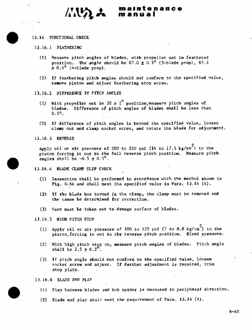
’ni ~ii i a t a i~ $:~i a a
iin a nua I
1ji16 CHECK
13.1~.1 FEATHERING
(1) Measuire pitch a~igi&s o‘f blades´•, with propeller set in feathered
po’sition. The angleshbuld be 8j;df´•0.50 (5-biade prop), 87.5
f 0.50 (4-blade prop).
(2) If ~eathering pitdh angi~s should not to the specified value,remo~ie pistori and adjust feathering stop scr~w.
13.16,2 DIFFERENCE IN PITCH ANGLES
(1) With set in 36 Id positionjmCasure pitch angl~s of
blades. Difference of pitch angles of blades shall be.less than
0.20.
(2) If difference of pitcharigles is beyond the specified value, loosen
ciampnut andclamp socketscrew, and rotatethe blade for adjus~tment.
13.16.’3 REVERSE
Apply oil or air pressure of 200 to 250 psi (14 to 17.5 kg/cm2) to the
piston forcing it outto.the full reverse pitch position. Measure pitchangles shall be -6.5 f Q.50
13.16.4 BLADE CLAMP~SLIP CHECK
(1) Inspection shall be performed in accordance with the method shown in
I Fig. 6-56 and shall meet f~e specified:value’in Para. 13.14 (4).
(2)~ If the blade has rurned´• in:the clamp~, the ciampmust be´•removed and
the cause be determinedfor correction.
(3) Care must be taken not’to damage surface of blades.
13.16.5 HIGH PITCH STOP-
(1) Apply oil or air pressure of-1OD to 12j psi (7 to 8.8 kgjcm2) to. the
piston, forcing it:´•out to the reverse pitch position. Bleed pressure.
(2) With high pitch stopon, measure pitch angles of blades. Pitch angleshall be 2.5 f 0.2
(3~) If pitch angle. should not:conforin:to ~the:´•specified value, loosen
socket screw andadjust. If further adjustment is required, trim
stop plate.
13.16.6 BLADE END PLAY
(1) Play between blades and.hub spider is measurdd.in peripheral direction.
(2) Bladeend play shall meetthe requirement of Para. 13.14 (1).
6-65
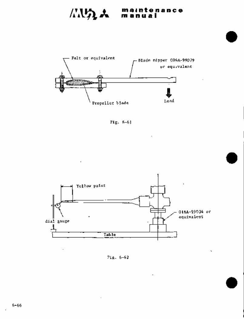
tn a PO II a Dnoa On t a a a a a a
Pelt br equivaientrBlade nipper 016A-99079
or equivalent
PLoad
Propeller blade
Pig. 6-61
Yellow paint
:016A-519rJ34 orequivalentdial gauge
Table
Fig. 6-62
6-66
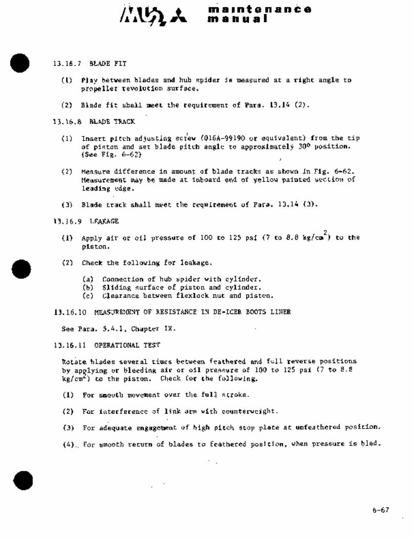
m a a ~h a im a ii nt ici.ao a 91 a a
a 13.16.7 BL~DB PIT
(1) Play between blades and hub spider is measured at aright angle to
propeller revolution surface.
(2) Blade fit shall meettherequirement of Para~ 13.14 (2).
13.16.8 BLADE TRACK
(1) Insert´•pitch adjusting sd~ew (0168-99190 the tiPof piston and set blade pitch angle to approximatel3 300 position.(See Pig.~ 6-62)
(2) MeasuicC difference in amount~ of blade tracks as shown in Fig. 6-62.
Measurement may be madti? at inljoard end of yellow painted section of
leading edge.
(3) Bladetradk shall meetthe requirement ofPara. 13.14 (3).
13.16.9 LEAKAGE
(1) Apply air or oil pressure of 100 to 125 pal (7 to 8.8 kg/cm2) to the
piston.
(2) Check the following for leakage.
(a) Connection of hub spider with cylinder.(b) :Sliding surface of piston and cylinder.(c) Clearance betweenflexlock nut and piston.
13. 16. 10 ’.MEASUREMENT OF RESISTANCE IN DE-ICER BOOTS’ LINER´•
See’ Para. 5.4.1, Chapter. IX.
13116.11 OPERATIONAL TEST
Rotate blades several times between feathered and full reverse positions
by apqlying or b~leeding air or ail pressure of 100 to 125 psi (7 to 8.8
kg/cm )..fo the piston. Checkfor the following.
(1) For smooth movement over the´•full stroke..
(2) For interference of link arm with counterweight.
(3) For adequate ´•engagement of high pitch-stop plate at unfeathered position.
(4).~ For smooth return of blades to::feathered position, when pressure is bled.
6-67

%i~jS f, rm 8 I n 8 n ~P 8 Qino 8 n 111 8
14. A_Ej~j TLTRsiNE TEMPERATijRE SYSTE~i
14.1 G~NERAL
This system is, to limit maxim~im torque and maximum interstage turbine
temperature automatically to the presetting values (mslximum torque1002, maixiniu‘m ITT 9230).This paragraph describes the electric system only. For the Gysteni desc~ip-tion pertaining to the engine, see AiResearch Maintenance.ManuB1.
14.2 OPERATION (See Fig. 6-63)
This system actuates when circuit breaker ENGINE POWER AUTO LIMIT on the
circuit breaker panel is closed and ENG PWR LIMIT switch on the LH switch
panel is placed to the AUTO position.
This system operation is that a torque signal from torque transducer, and
an interstage turbine temperature signal from engine thermocouple are sent to
the limiter controller installed on the RH side of main junction box, and
if torque exceeds 100% or interstage turbine temperature exceeds 9230C, the
torque motor bypass valve is driven and engine torque or interstage turbine
temperature is automatically reduced to the presetting values by bypassingfuel to boost pump inlet and decreasing fuelto engine. Even if either
torque system or interstage turbine temperature system fails, the other
system can be operated normally.
When ENGINE PWR LIMIT swi.tch is placed to MAN, this system is inoperative.
14.3 SYSTEM CHECK
(1) After engine starting, set condition l-~ver to TAKEOFF-LAND and set
engine rpm to 100% by power lever.
(2) Ascertain that ENG PWR LIMIT switch is in the AUTO position and c~cuit
breaker ENGINE POWER AUTO LIMIT is closed.
(3) Set PWR AUTO LIMIT TEST switch, on the center instrument panel, to
TORQUE and hold for about 2 seconds and ascertain that fuel decreases
and engine rpm reduces about 3%.
(4) Set PWR AUTO LIMIT TEST switch to ITT. and hold for about 2 seconds and
ascertain that fuel flow decreases and engine rpm red~ces´•about 3%.
(5) Advance power lever and ascertain that engine power is limited to 100%
torque or interstage turbine temperature 9230C.
6-68

~t´• m a s to t a a a a a a
manuai
DC 28V
ENG POWER AUTO LIMIT
UE METE
Torque meter
Torque PressureIn te~s tage
TransducerTurbine Temp.Indicator
Interstage Turbine Temp.
ThermocoupleITORQUEI
Governor I I I I I I I 1 1 IITTI
Power Auto Limit Test SW.
Torque Motor BypassIAUTOI
Valve
o LMANI
Power Auto
Limit Switcho a,
O)o Q)~ta, ~:4 Uk
aPk O S:
f
1 aS
E-lo
m k
ra) ’3~ h)hO bD PI
Miij iiip,
V1
B E~e"a k
F~ a,~E S~m
o",~-IFl.a C: E
Torque’ and Interstage Turbine Temp. Control Sys.Limiter Controller
Fig. 6-:63
6-69

ma~ntenancemanual
15. SYNCHROPHASER SYSTEM
15.1 GENERAL DESCRIPTION
The synchrophaser is a system which is installed as an aid to the pilot to
maintain identical engine rpm of both engines. It automatically matches
the engine rpm and the phase.relationship between the propellers. The
system operates within a predetermined range limit, approximately 2%.
There are three major components: magnetic pickups, control box and
actuator. The magnetic pickups are located in the propeller governor for
each engine. The control box is located in the cockpit and contains all
the necessary transistorized circuitry to maintain both engine rpm and
propeller blade angle phase. The actuator is a stepping type motor
that operates on command from the control box and is mounted on the slave
(right) engine nacelle.
15.2 OPERATION
Electrical pulses from each magnetic pickup are fed into the control box
where they are compared. Any difference in these pulse rates or phasingpulse position will cause the control box to run the actuator motor and,through the flexible shaft, trim the slave (right) engine propellergovernor speed setting to match the master (left) engine rpm and preset
phase relationship. Normal propeller governor operation is unchanged bythe synchrophaser and will continuously monitor engine rpm and propellerphase angle and reset the slave engine propeller governor as required.
NOT E
The synchrophaser should not be operating during
engine ground run operation, taxi, takeoff and
landing,
15.3 FUNCTIONAL TEST
To functionally test the synchrophaser on the ground, start both enginesand manually synchronize the rpm. Place the synchrophaser switch to ON,allow the engines to become synchronized. Slowly adjust, in small increments,the master (left) engine propeller governor to increase and decrease the
rpm. The rpm range over which the slave~ (right) engine remains synchronizedwith the master engine is limited to approximately 2%. With the synchrophasernear its travel end, turn the system OFF, allow the actuator time to return
to its mid-position, then turn the system ON again; synchronization should
result.
I
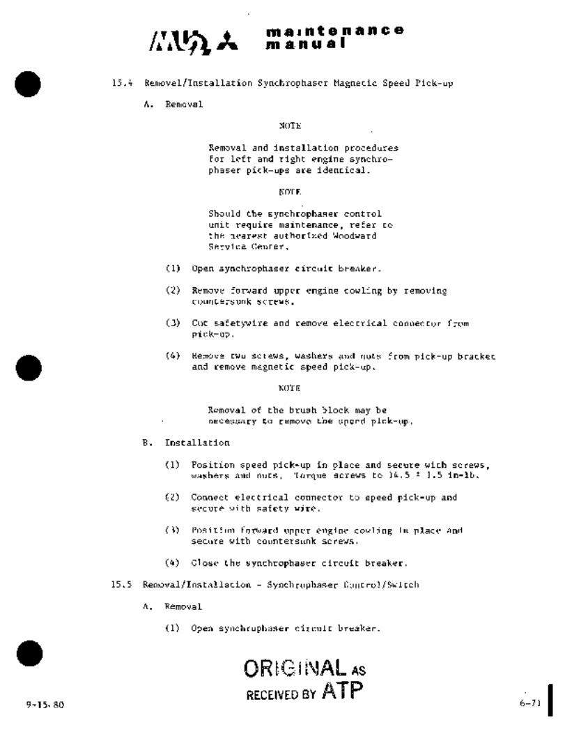
C~g It ma´•lntenalncemanual
15.4 Removal/installation Synchrophaser Magnetic Speed Pick-up
A. Removal
NOTE
Removal and installation proceduresfor left and right engine synchro-phaser pick-ups are identical.
NOTE
Should the synchrophaser confrol
unit re´•quire maintenance, refer to
the nearest authorized Woodward
Service Center.
(1) Open synchrophaser circuit breaker.
(2) Remove forward upper engine cowling by removingcountersunk screws.
(3) Cut safetywire and remove electrical connector’ from
pick-up.
(4) Remove two screws, washers and nuts from pick-up bracket
and remove magnetic speedpick-up.
NOTE
Removal of ~he brush blockmay be
necessary to remove the speed pick-up.
B. Installation
(1) Position speed pick-up in place and secure with screws,
washers and nuts. Torque screws to 14.5 1.5 in-lb.
~2) Connect electri’cal connector tospeed pick-upandsecure with safety wire.
(3) Position forward upper engine cowling in place and
secure with countersunk screws.
(4) Close the synchrophaser circuit breaker.
15.5 Removal/Installation Synchrophaser Control/Switch
A. Removal
´•(1) Open synchrophaser ’circuit breaker.
BRsGr~JAe As
APP I9-15-80 6-71

maintenancema-nu a. I
(2) Remove radio control panel, radar indicator an~
radar mounting rack.
(3) Remove nut and washer from synchrophaser toggleswitch.
(4) Remove electrical connector from toggle switch and
remove switch.
(5) Remove electrical connector from synchrophaser control
box.
NOTE
Removal of additional electrical connectors
to other equipment may be necessary for
acc’ess and removal of the control box.
(6) Remove screws from control box and remove box..
B. Installation
(1) Position control box under-dash and secure with screws.
(2) Connect electrical connector to control box and connect
electrical connectors removed for access.
(3) Connect electrical connector to toggle switch and
position switch in panel.
(4) Secure switch to panel with washer and nut.
(5) Position radio~control panel in place and secure.
(6) Close synchrophaser circuit breaker.
NOTE
With the propeller loaded aft, the minimum
gap between the synchrophaser support bracket
and spinner backing plate must be .050 in.
measured around the diameter.
9-15-80

~5 It maintenancemanual
16. CONTINUOUS IGNITION SYSTEM (If installed)
16.1 GENERAL DESCRIPTION
The continuous ignition system provides independent ignition switchin each ignition circuit, and allows engine ignition as required.This system is used to prevent engine flame out during takeoff,
flight or landing under adverse weather conditions, especially when
icing weather condition exists or may exist.
16.2 OPERATION TEST (See Fig.6-64)
(1) Remove access door from center wing leading edge.
(2) Disconnect the left and right engine switch connectors and connect a
20 AWG jumper wire between pins E and F of the respective airframe
plug.
(3) Restore electrical power, battery or APU.
(4) hull the BA~RY key switch ON.
(5) Place the RUN-CRAM(-STOP switches to RUN.
(6) Place the continuous ignition snitch ON, left then right. The
respective ignition light should illuminate to confirm ignition unit
function
~C*UTION ICAUTION
Do not exceed 10 seconds operating time during this
test
NOVE
Operation may also be verified by an audible click
from the respective ignition unit.
(7) Remove the jumper wire and restore the speed switch plugs.
(8) Start the engines in accordancewi´•t~h the applicable Airplane FlightManual. Ensure that simultaneous illumination of the ignition lightand engine start switch light does not occur during engine start.
NOTE
The continuous ignition switches must be OFF duringthischeck.
3-31-90 6-73
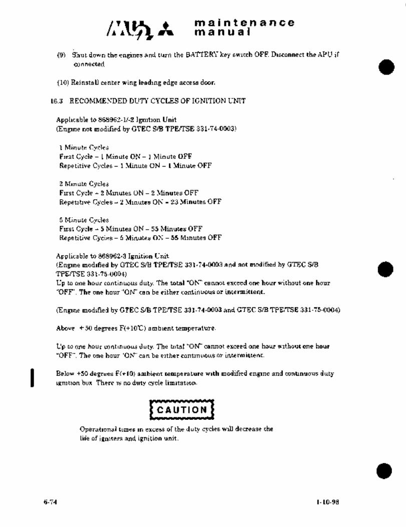
/´•’~;5maintenancemanual
(9) Shut down the engines and turn the BATTERE’ key switch OFF. Disconnect the APU if
(10) Reinstall center wing leading edge access door.
16.3 RECOMMENDED DUTY CYCLES OF IGNITION UNIT
Applicable to 868962-1/-2 ignition Unit
(Engine not modified by GTEC S/B TPEITSE 331-74-0003)
1 Minute CyclesFirst Cycle 1 Minute ON 1 Minute OFF
Repetitive Cycles 1 Minute ON 1 Minute OFF
2 Minute CyclesFirst Cycle 2 Minutes ON 2 Minutes OFF
Repetitive Cycles 2 Minutes ON 23 Minutes OFF
5 Minute CyclesFirst Cycle 5 Minutes ON 55 Minutes OFF
Repetitive Cycles 5 Minutes ON 55 Minutes OFF
Applicable to 868962-3 Ignition Unit
(Engine modified by CTEC S/B TPE/TSE 331-74-0003 and not modif~ed by GTEC SIE
TPE/TSE 331-75-0004)
Up to one hour continuous duty. The total "ON’ cannot exceed one hour without one hour
"OFF". The one hour "ON’ can be either continuous or intermittent.
(Engine modified by GTEC S/B TPEPTSE 331-74-0003 and GTEC SIE TPEPTSE 331-75-0004)
Above 50 degrees F(+1O"C) ambient temperature.
Up to one hour continuous duty. The total "OK’ cannot exceed one hour without one hour
"OFF". The one hour "OW’ can be either continuous or intermittent.
I Below +50 degrees F(+10) ambient temperature with modified engine and continuous duty
ignition box. There is no duty cycle limitation.
J~UTIONICAUTION
Operational times in excess of the duty cycles will decrease the
life of igniters and ignition unit.
6-74 1-10-98

maintenancemanual
I
_~Ln RH~_
O ~e-L\IGNITION LIGEF~
oN oH
oFFIGNITION SWITCH conrlHlous
~cniTion
Ignition Switch Detail
Fig 6-64 Ignition Switch Installation
3-31-90 6-75
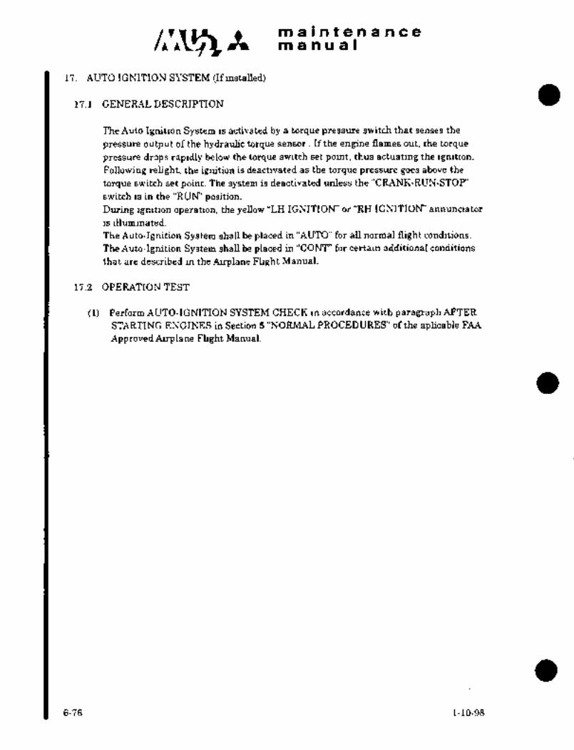
maintenancemanual
l’i. AUTO IGNITION SYSTEM ~finstalled)
11.1 GENEh4LDESCRIPI~loNa
The Auto Ignition System is activated by a torque pressure switch that senses the
pressure output of the hydraulic torque sensor If the engine flames out, the torque
pressure drops rapidly below the torque switch set point, thus actuating the ignition.
Following relight, the ignition is deactivated as the torque pressure goes above the
torque switch set point. The system is deactivated unless the "CRANK-RUN-STOP"
switch is in the "RUW’ position.
During ignition operation, the yellow "LH IGNITION’ or "RH IGNITION’ annunciator
is illuminated.
The Auto-Ignition System shall be placed in "AUTO" for all normal flight conditions.
The Auto-Ignition System shall be placed in "CONT"’ for certain additional conditions
that are described in the Airplane Flight Manual.
1’i.2 OPERATION TEST
(1) Perform AUTO-IGNITION SYSTEM CHECK in accordance with paragraph AFTER
STARTING ENGINES in Section 5 "NORMAL PROCEDURES" of the aplicable FAA
Approved Airplane Flight Manual.
6-76 1-10-98

CHAPTER
FWEL SYSTEIVI

maintenancemanual
CHAPTER VII
FUEL SYSTEM
CONTENTS
i. GENERAL DESCRIPTION 7- 1
1.1 MAIN FUEL SYSTEM 7-2-1/7-2-2
1.2 AUXILIARY TANK FUEL SYSTEM 7- 3
1.3 FUEL ADDITIVES 7- 3
2. FUEL FEED SYSTEM 7-(7)8
2.1 BOOST PUMP 7-(7)8
2.2 FUEL SHUTOFF VALVE 7-10
2.3 FUEL FILTER 7-12
2.4 BC~ST PUMP WARNING SWITCH 7-14
2.5 FUEL LOW LEVEL WARNING SWITCH 7-14
2.6 MANIFOLD 7-15
3. FUEL VENT SYSTEM 7-15
3.1 CENTER TANK VENT VALVE 7-17
3.2 OUTBOARD TANK VENT VALVE 7-17
3.3 OUTER TANK VENT VALVE 7-17
4. INTEGRAL TANK 7-19
5. TIP TANK FUEL SYSTEM 7-20
5.1 FUEL TRANSFER SYSTEM 7-20
5.2 AIR SHUTOFF VALVE 7-20
5.3 AIR PRESSURE REGULATOR 7-20
5.4 FUEL SHUTOFF VALVE 7-21
5.5 FUEL LEVEL CONTROL VALVE 7-22
5.6 SNIFFLE VALVE 7-23
5.7 TIP TANK 7-23
5.8 OPERATIONAL CHECK AFTER TIP TANK INSTALLATION 7-26
5.9 OPERATION CHECK OF TIP TANK FUEL TRANSFER 7-27
5.10 STRAINER 7-28
3-31-90 7-i
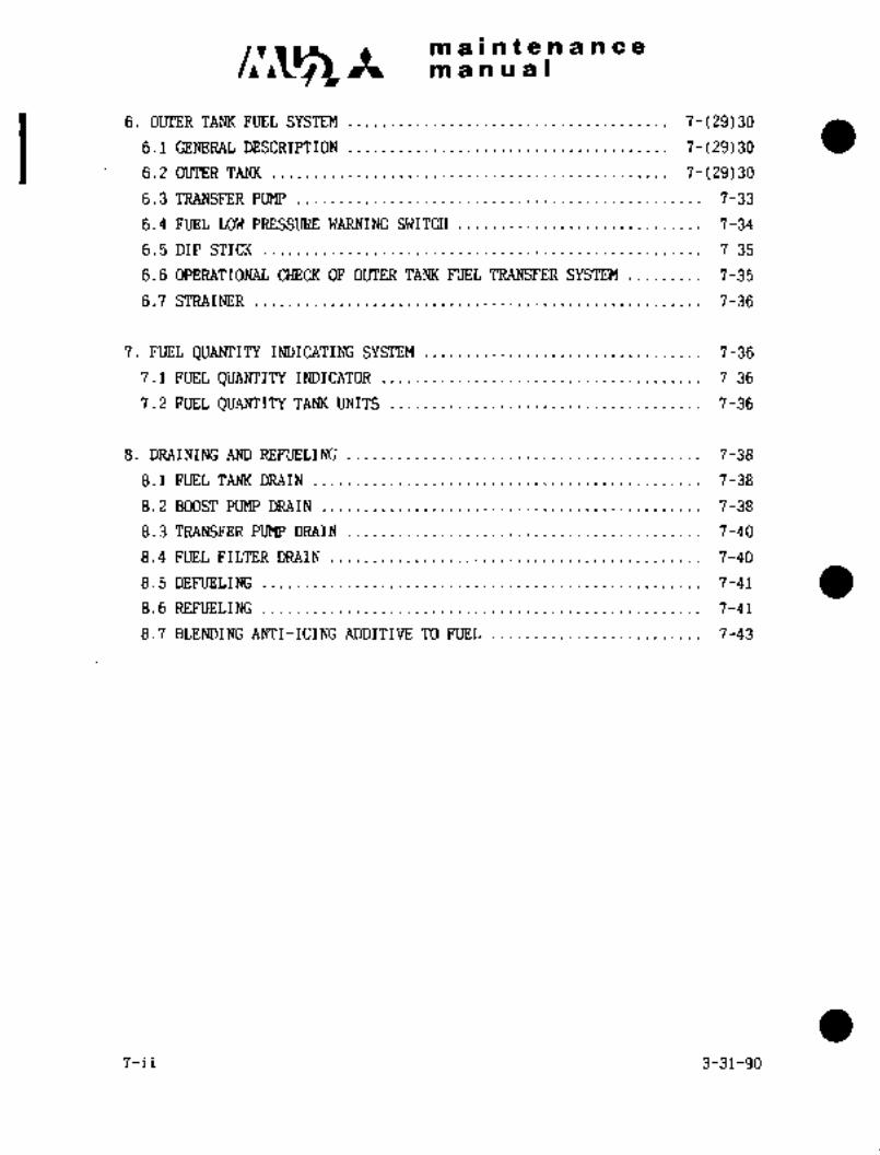
maintenancemanual
6. OUTER TANK FUEL SYSTEM 7-(29)30
6.1 GENERAL DESCRIPTION 7-(29)30
6.2 OUTER TANK 7-(29)30
6.3 TRANSFER PUMP 7-33
6.4 FUEL LOW PRESSURE WARNING 7-34
6.5 DIP STICK 7-35
6.6 OPERATIONAL CHECK OF OUTER TANK FUEL TRANSFER SYSTEM 7-35
6.7 STRAINER 7-36
7. FUEL QUANTITY INDICATING SYSTEM 7-36
7.1 FUEL QUANTITY INDICATOR 7-36
7.2 FUEL OUANTITY TANK UNITS 7-36
8. DRAINING AND REFUELING 7-38
8.1 FUEL TANK DRAIN 7-38
8.2 BOOST PUMP DRAIN 7-38
8.3 TRANSFER PUMP DRAIN 7-40
8.4 FUEL FILTER DRAIN 7-40
8.5 DEFUELING 7-41
8.6 REFUELING 7-41
8.7 BLENDING ANTI-ICING ADDITIVE TO FUEL 7-43
7-ii 3-31-90

maintenancemanual
i. GENERAL DESCRIPTION
The fuel system consists of the following systems (See Fig. 7-1).
Main fuel system System which feeds fuel from wingtank to engines.
Tip tank fuel system System which transfers fuel from tiptanks on the wing tip to the wingfuel tank.
Outer tank fuel system Systemwhich transfers fuel from
outer tanks in the outer wing to
the main fuel tank.
Fuel Specifications The following lists the approved fuels.
(1) Aviation Turbine fuels ASTM D 1655-68T Types Jet A, Jet A-1
and Jet B
(2) MIL-T-5624-1 Turbine Fuel Grades JP-4 and JP-5
(3) MIL-F-5616-1 Fuel Grade JP-l
(4) Ma-F-46005 (MR)-1 Types r and II
(5) British Ministry of Supply Specifications(a) D. Eng. R.D. 2482 Issue No. 2
(b) D. Eng. R.D. 2486 Issue No. 2
(c) D. Eng. R.D. 2494 Issue No. 4
(6) MIL-G-5572 Aviation gasoline (emergency fuel use only)(a) Grade 80/87 octane
(b) Grade 100/130 (low lead) octane
CAUTION
Avoid operations above 10,000ft. msl when using aviation
gasoline.
Anytime the mixture of aviation
gasoline to turbine fuel is 25%
or more, add one quart of avia-
tion grade oil (MIL-L-6082,Grade’ 1065 or 1100) per 100
gallons of aviation gasolineto the fuel mixture.
(a) Grade 80/87 octane aviation gasoline maybe used as emergency fuel only. The amount
mustnot exceed 1,000 gallons per engine foreach 100 hours of engine operation.
(b) Grade 100/130 (low lead) aviation gasolinemay be used as emergency fuel only, The
amount must not exceed 250 gallons per enginefor each 100 hours of operation. Maximumtotal usage is 7,000 gallons per engine duringany 3,000 hour period.
7-1
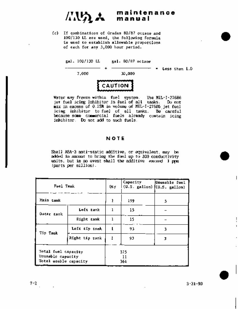
c~rmaintenancemanual
(c) If combinations of Grades 80/87 octane and
100/130 LL are used, the following formula
is used to establish allowable proportionsof each for any 3,000 hour period.
gal. 100/130 LL gal. 80/87 octane
Less than 1.0
7,000 30,000
CAUTION
Water may freeze within fuel sys tem. Use MIL-I-27686
jet fuel icing inhibitor in fuel of all tanks. Do not
mix in excess of 0.1596 in volume of MIL-I-27686 jet fuel
icing inhibitor to fuel of all tanks. Be carefulbecause some commercial fuels already contain icinginhibitor. Do not add to such fuels.
NOTE
Shell ASA-3 anti-static additive, or equivalent, may beadded in amount to bring the fuel up to 300 conductivityunits, but in no event shall the additive exceed 1 ppm(parts per million).
Capacity le fuelFuel Tank Qty (U.S. gallon) J(U.S. gallon)
Main tank 1 159 5
Left tank 1 15Outer tank
Right tank 1 15
Left tip tank 1 93 3Tip Tank
Right tip tank 1 93 3
Total fuel capacity 375Unusable capacity 11Total usable capacity 364
7-2 3-31-90

maintenancemanual
I´•I MAIN FUEL SYSTEM
The main -fuel system consists of three integral tanks in wing center section,right and left wing outboard sections (W STA 580 to 1950), two boost pumps
for supplying fuel to both engines, two fuel shutoff valves, two fuel filters,two boost pump warning switches, manifold check valve, tubing, hoses, fuel
quantity transmitter, fuel flow transmitters, etc.
The three integral tanks are interconnected to act as one fuel tank, havinga total capacity of 159 U.S. gallons including unusable fuel of 5 gallons.The fuel filler port is located on~top of outboard tank. The fuel in the
tanks flows into the center tank by gravity. Between the center tank and
outboard tanks, a check valve is provided to prevent the reverse flow of fuel.
Boost pumps are located at the left rear and right center bottom inside the
center tank. Through these pumps, fuel is injected under pressure into the
manifold located on the front wall in the center tank. The boost pumps
supply fuel to both engines through the manifold. The fuel flows out of
the manifold, departs right and left, and is delivered under pressure
through the electric-motor operated fuel shutoff valves and the fuel
filters to both engines.
3-31-90 1

iii 8 t 88 ii~ ii 6 i~
~n-a H iu a I
The bodsti Pump ail is on the right-hand
PI~P FAIL on the annuriciafo~ pariel of cockpitsddeof the cente~ tanki alid aut.oinatically iliiirhinates the lights of BOOST
the upper
part of the instrument panel, when fuel pressure falls b~low 3.2 psi,iridbcating the presefice of t~ouble in the In the center tank and
outboard t.aTiks, capacitor ’tyiie ruei quantity transmitters are mounted to
show the total quantitl of fuel in the tanks.
1;2 AUXILIARY TANK FUEL SYSTEM
Auxiliary tank fuel System consists of tip tank fuel system and outer
tarik fuel system.
1.2.1 TIP TANK FUEL SYSTEM
This systemconsists of tip tanks (93 U.S. gallons each) mounted at
the wing´•tips, airpressure shutoff valve, air pressure regulator,fuel shutoff valves, fuel level control valve, and tubing. The
fuel in the tip tanks is transferred into the center fuel tank byair pressure. Fueltransfer from the tip tank to the center tank
is controlled bythe fuel levelcontrol valve´•installed in the
center tank.
1.2.2 OUTER TANK FUEL SYSTEM
This system consists of outer tanks(l5U.-S. gallons-each) mounted
at the LH and RH outer wings, transfer pumps,,fuel low pressure
warning switch, check valve, vent valve, dip stick, and tubing.The fuel in the outer tanks is transferred into the center tank bytransfer pumps, flowing together with the tip tank fuel transfer line.
1.2;3 CONTROL OF AUXILIARY TANK FUEL SYSTEM
Tip- tank and outer tank fuel is transferred in AUTO or TIP MANUAL
mode. InAUTO mode, tip tank fuel andouter.tank fuel is trans-.
ferred in turn,selecting automatically. TIP MANUAL mode is used
when AUTO mode is defective and only tip.tank fuel is transferred.
Mode is selected by placing FUEL TRANSFER switch to AUTO or TIP
MANUAL
1.3 FUEL ADDITIVES
1.3. 1 ANTI-ICING ADDITIVES.
Fuel system icing´•inhibitors which conform to MIL-I-27686 are accep-
table- for use with fu’elwhich is not premixed.with anti-ice additives.
The -amount of, additive to be used in the fuel should not exceed 0;15%
:(nlaximum) by volume.
For blending procedures, seeParagraph 8.7.
1.3.2 ANTI-STATIC.ADDITTVV
SHELL ASA-3 anti-static additive(or equivalent) is approvedfor use
in amounts torais’e the fuel up to300 conductivity units, except
that in no case shall the additive concentration exceed 1.0 ppm.
7-3

CI1~A in ~a II ii t a ii a in a a
in a n Iii a I
1.3.3 MICROBICIDE ADDITIVE
Microbicides should not be us~d in fuels unless there is presence of
foreign organisms or conditions are such that their presence may be
anticipated. In such instances Sohio Biobor JF Biocide (mfg. by U.S.
Borax) or equivalent may be used in the fuel for pesticide and microbicid~
purposes in amounts not to exceed 270 ppm maximum for the initial sterili-
zation, and 135 ppm for continuous usage or intermittent use.
Should there´• be an indicated presence of micro-organisms in the fuel
system, it is recommended to use the biocide additive for a minimum of
three months or 600 hours of engine operation. The initial steriliza-tion level (270 ppm) should be maintained at least 72 hours before
adding untreated fuel.
Should conditions require continued use, stored ~fuel may be pre-mixedwith the biocide additive in amounts not to exceed 135 ppm.
The bioclde may be meter blended with the fuel during the fuelingprocess or by batch blending. When batch blending, the biocide should
be added while the tank is approximately 1/2 full.
NOT E:
Complete mixing is necessary
for fungicidal activity.
The following chart lists the required amount of biocide to be
blended with various fuel tank quantities. The biocide requirementis based on a fuel weight of 6.7 Ibs/gal for this chart. To blend
with other fuels, multiply the amount of fuel in pounds by 0.004;this will give the amount of biocide in fluid ounces required to
meet the270 ppm requirement (use afactor of 0.002 for 135 ppm).
7-4
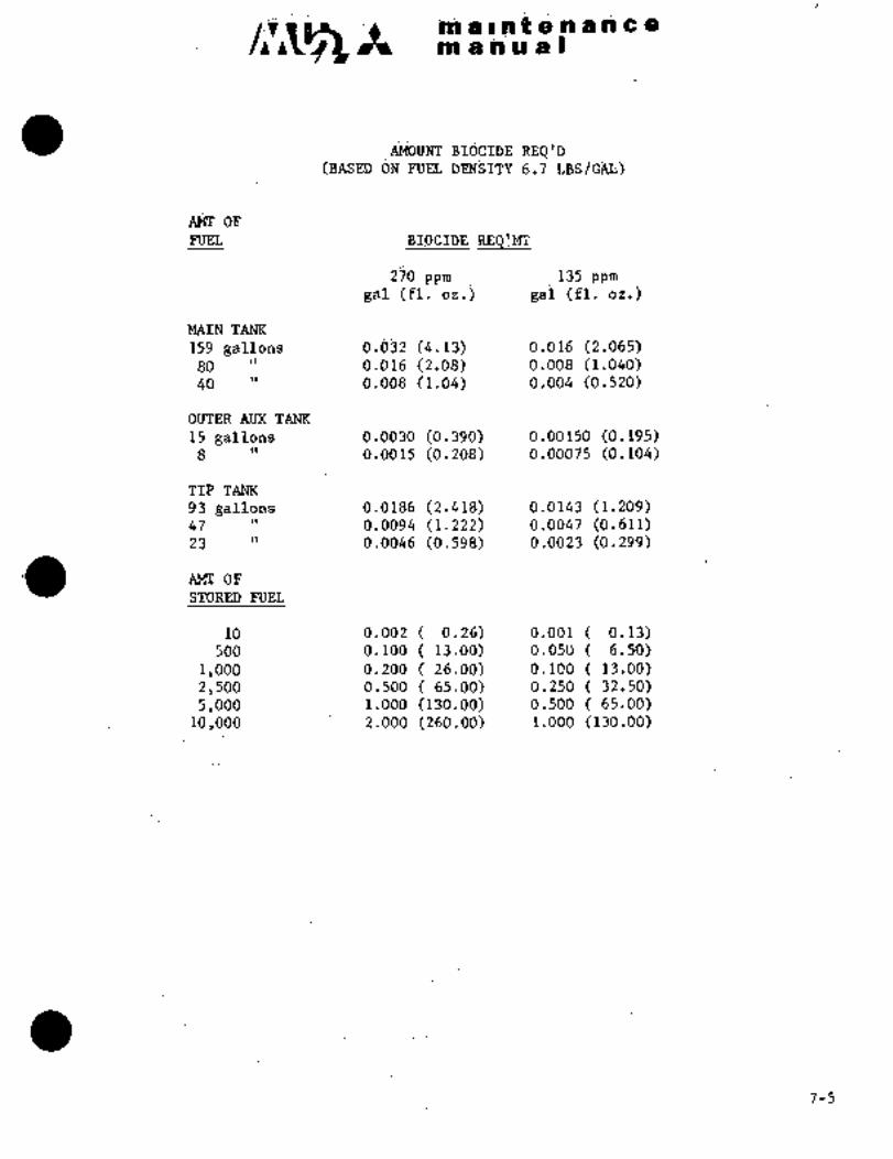
REQ’ij(BAS;I~D ON FrEi; 6;7 LBS/Gi4I;)
’oPPnj’EL REQar~
270 ppm 135 ppm
gal ;(fl. ~iij gai (fl. oz;)
MAIN TANK
159 gdllons 6.bSi i4ii3) ~;016 i2.065)80 1’ 0;016 (2.08) 0;008 (1.040)40 d.008 0.004 (0.520)
ijUTER AUX TANK
is gallons (0.39d) 0.06150 (0.195~8 o.oois (0.208) 0.00075 (0.104)
T~P TANK
93 gallons ’0.0186 (2.418) 0.0143 (1.209)47 0.0094 (.1.222) :0.0047 (0.611)23 0;0046 (0.598). 0´•.0023 (0.299)
AE´•TII OF
STORED FUEL
10 0.002 0.26) 0.001( 0.13)500 0.100 13.00) 0.050 6.50)
I, ooo ´•0.200 26.00) 0.100 13.00)2,500 ..~0.500 65.00) 0.250 (~32.50)5,000 1~;00T)‘ (136.00) 0.500( 65.00)
io ,ooo 2’. 000~’ (260.00) 1.000 (130.00)
7-5
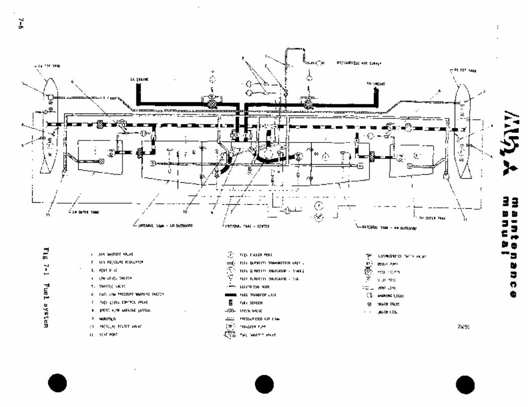
a\
PRESSURI~ED AIR SUPPLY~LH TIP TANK 2
~RH TIP TANK
’LH ENGINE
a 46
RH ENGINE3~ I 6
e
t´•
s .4
ss 1 jj Ct’
F p-O
9
:F BP .rp?
LY f~ I_ U qn ill ii
L~--’---f--
f 33DUfER TATX )O 9
7c--~i11 r\ i P´•~.
TANK LN w~onao1 i
RN OUTER ~ANI 11
7ANK tEmR3 Z~
INTEGRAL TANY RH OLiTBa4RD
i~´•
3)- (3rr-´• 1. AIR YIUTOFF VALVE O F:IEL FILLER PORT
´•I
OQ 9 INTERCONNECT VALVE
2 AIR PRESSURE REGULATOR cEt FUEL OUANTITY TRANSMITTER UNIT
3. VEMOISC FUEL QUANTITY INDICATOR SIHGLE
BOOST pUnpFCCCF1CTER
3)
4. LOU LEVEL SNITCH r\r‘. FUEL QUANTITY INDICATOR OUAI YENTPOCi
r 5. SHIFFLf~ALYE ~mh ELECTRICAL UIRE3)
VENT tl?iE
(3C 6. FUEL LhN PRESSURE YARNI1(G SNITCH FUEL TRANSFER LINE YARNIHGLIGHT
7. FUEL LEVEL CONTROL VALVE FUEL SCREEI OW\INVALVE
8. BOOST PUMP NARNING SNITCH =I~F´• CHECK VALVE ~RAINLIIIE
9. MANIFOLD TTZZZ PRESSURIZED klR 1INE
10. PRESSURE RELIEF VA~VE i~ TFaNSFIRP~P 250~1
Il. VEliTPOR7 FUEL SHUTOFF VALVE

Cllri3A kip a i n~ ii ii g a c a;i
~m a iii a a I
2. FUEL FEED SYSTEM
Fuel in the wing tanics flows into the center tank by gravity. A check
valve is located betwee~ the center tarik and outboard tanks to preventreverse flow of fuel.
Fuel is fed into the manifold mounted in front of the tank b~ two boost
pumps in the center ta~nk. A boost pump warning switch is mounted in front
of the center tank, and turns on the light of BOOST PUMP FAILon the
ahnunciator panel o~ the cockpit and of CAUTION on the instrument panel,to indicate the presence of trouble when fuel pressure has droppedbelow 3.2 psi,
Fuel flow branches off into two lines at the manifold and passes throughthe fuel shutoff valve and flows into the fuel filter. Filtered fuel is
fed through the fuel line to the ~fueL inlet of. the engine. ~In case the
fuel filter becomes:blocked with dirt, the’fuel flows through the bypassvalve to each engine.
2.1 BOOST PUMP
Theboost pumps are constant-speed, centrifugal, submerged type pumps
located one each at the left rear and right center bottom of the cenrerfueltank. These pumps´• are operated by closing the circuit breaker BOOST
PUMP. The boost pump is designed to operate on 28 volt 10 amp DC´• power,
has a.capacity of O to 2,000PPH of flow rate at 14.1 to 50 psi (0.9 to
3.5 kg/cm2) of delivery pressure, which is sufficient to operate both
engines at the same time with one pump operational. The electrical
wiring to the pumps is designed to operate both pumps when either engine
has malfunctioned.
7-(7)8
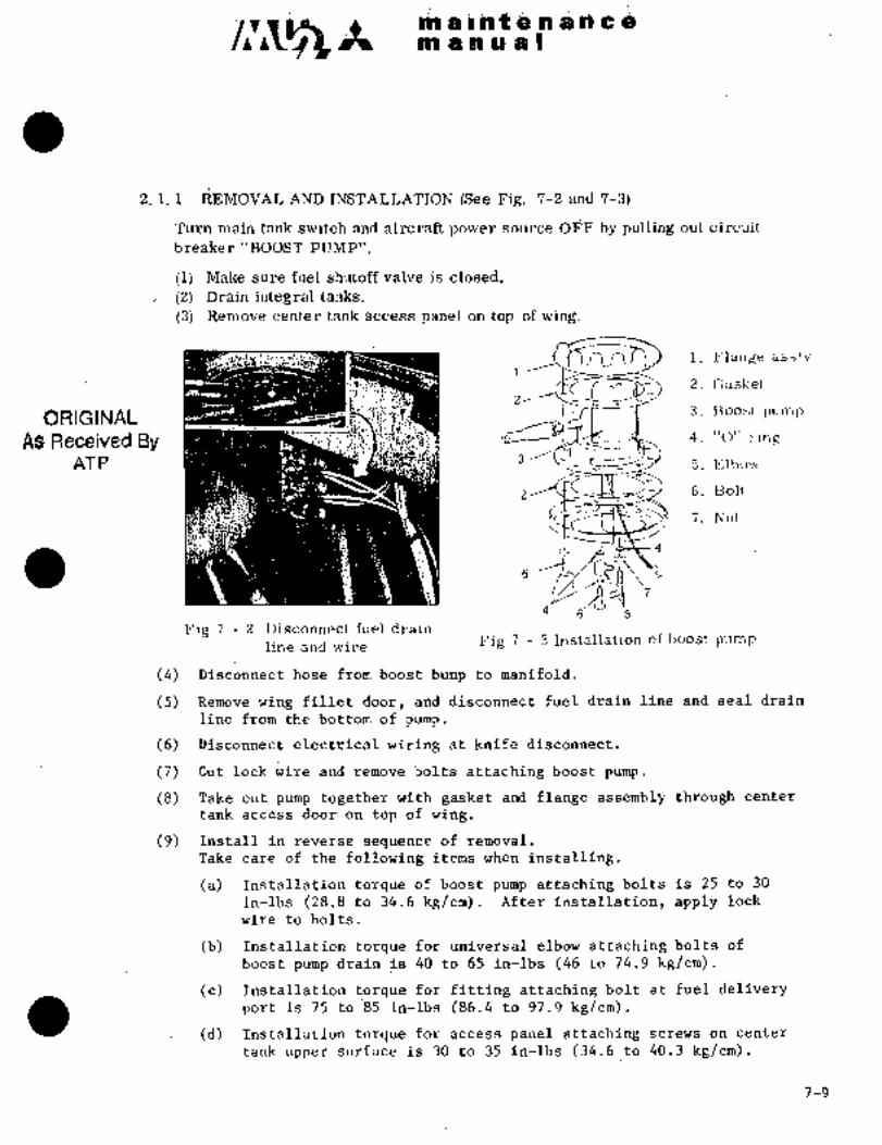
c~A C iis f Q ~i PB a iE~
e~ a a a a 8
2. i. 1 ~EiEMOVAL (S$e Fig. 7-2 ada 7-3)
Turn main tank switci~ and aircraft power source O‘E;F by pulling out circuit
breaker "BOOST PUMP".
(i) Make sure fuel shutoff valve is closeci,
(2) Drain integral tanks.
(3) Remove center tank acces’s pahel on top of wing.
i. Flange ass’y
2. Gajket
ORIGINAL 3´• BOOSt pump
As Received By 4: 110" ring
AT P 5. E~how
6. Bolt
7. Nut
4
4"465
Fig 7 2 Disconnect fuel drain
line and wire Fig 7 3 Installation.of boost pump
(4) Disconnect hose -from boost bunp to manifold.
(5) Remove wing´•filletdoor, and’disconnect fuel drain line andseal drain
line from the bottom of pump.
(6) Disconnect~electrica1 wiring at knife d~sconnect.
(7) Cut lock wire and remove´• bolts attaching boost pump.
(8) Take out pump together´•with gasket and flangeassembly through center
tankaccess door on top of wing.
(9) Install in reverse sequence of removal.
Take care of the following items when installing.
(a) Installation torque of boost pumpattaching bolts is 25 to 30
in-lbs (28.8 to 34.6kg/cm). After installation,. apply lock
wire to bolts.
(b) Installation torque for‘´•´•universal: elbow attaching:bolts of
boost pump drain is..4d to.65 !in-lbs (46 to 74.9 kg/cm).
(c) Installation torque for fitting attaching bolt at fuel delivery
port is 75 to::85- inilbs (86.4 to’97;9: kg/cm).
(d). Installationtorque for accesspanel attaching screws on center
tank upper surfaceis 30 to 35.in-lbs- (34.6.to 40.3kg/cm).
~7-9

in a irn te:bi a a i= am a a a a I
NOtE
Access panel of center tanli on top of wing should
be installec~l in correct position.Incorrect installation may cause fuel leakage.
NOTE
I’lace put-lip ~vith its fuel deliverji port: faced iii
proper clii´•ection when insl33ling.I-’roper direction of port is ;il,out 20
dcGrccS to the right: from front (flight direction) on
Icfl-j~alnl side pun~p and al,out 05 degrees to 1:he
left froln i’ront (f7ight clircc:tion) on right-handsitle punil,.
Opel-3lion check of I,oosi I,rim~-, is as follows:
(1) Close MASTER CAUTION circuit breaker and make sure that left
and right boost pump warning lights BOOST PUMP FAIL are illu-
minated.
(2) Close RH BOOST PUMP and LH BOOST PUMP circuit breakers and make
sure that left and right boost pump warning lights BOOST PUMP
FAIL go out.
(3) Make sure that operation noise of pump is normal, no leakagefrom pump section and drain line connecting sections, and that
leakage from the seal drain is less than 2 cc per hour.
(4) Pull out circuit breakers RH BOOST PUMP and LH BOOST PUMP. Left
and right boost pump warning lights BOOST PUMP FAIL should be
illuminated.
(5) Pull out circuit breaker MASTER CAUTION.
NOTE
Do not operate boost pump
in dry fuel condition.
2. 2 IE~UEL SI-1U"OFF VALVE
The fuel shutoff valve isa motor-operated gate valve, located on the
manifold at the center tank front outlet. To open the shutoff valve,close "SHUTOFF VALVE" circuit breaker and turn ’%LAIN TANK" switch to on.
To close the valve, turn the switch to off. In case of emergency such as
engine fire, trouble, etc., when the fire handle in´•the cockpit is pulledthe valve closes immediately. The valve is designed to close normally in
one second. The valve-driving motor operates on 18 to 30V DC power.
7-10

msinipaacseof~ re n to D
i. 2.1 A~N‘D ir;j8TAi~jLATION (See Fig 7-4)
(1) Drj~in integral tai~ks and ifLiel lines.
(2) Remove ceiiter wing front access panel.
(3) Discoiinect fuel line at the valve.
(4) Dis’connect elect’ric connector and bonding jump´•er.
(5) Remove two bolts to separate bracket from front spar of wing.
(6) Remove wi~idh connect shutoff valve and remove Shutoff valve.
(7) Install iii reiierse seclu8nce of removal.
Take care of the following items i;Nhen ihstalling.ORIGINAL
(a) Install "0’’ ring,lubk´•icatin$ with petrolatum (W-P-236). AS Received ByInstallation torque of~bolt connecting the valve and AT Pconnectoi~ to elbow is 50 to 70 in-lbs. (57.6 to 80.6
kg-cm)’*l, 20 to 25 in-lbs. ~23´•to 28.7kg-cm) -k2.
i. Shutoffvalve 5. Bracket
2. Elbow 6. Line
3. "0" ring 7. Front spar7
cJ4. Connector 8. Bonding jumper
´•1
2 8
6
31
5.~U ~I
"1 Aircraft S/N 652SA, ~61SAAircraft S/N 697SA and I-subsequent
Fig 7 4’ Inst~llation of fuel shutoff valve
2. 2. 2´•’OPERATIO~j CHECK
(1) Remove center wing front access panel.
(2)’ Close ’’BOOST PUMP" and "SHUTOFF VALVE" circuit breakers.
(3) Turn "MAIN TANK" switch to on.
(4) Make sure, th~itvalve ovei´•ride lever(Red) moves positively from FULL
CLOSE positionto FULL OPENposition and th‘at pressuredfuel flows out
when fuel hose:to engine is ~remdved?
(5, Turn "IIIAIN TANK" suitch to off: .OWIGI NAL ns
RECEIVED BY aBP 7-11
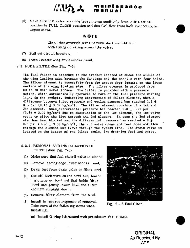
/I~lt meint~npne´•in a a a a)
16) Make sure that valve ojerride lever moves positively from FUEL OPEN
position to FULL CLOSE position and that fuel flow from hos’e connecting to
engine stops.
NOTE
Check that override lever of valve does not interfer
with tubing or wiring around the valve.
(7) Pull out circuit breaker.
(8) Install center wing front access panel.
2. 3 FUEL FILTER (See Fig. 7-5)
The fuel filter is attached to the bracket located at about the middle of
the wing leading edge between the fuselage and the nacelle with four bolts;
The filter element is accessible´•from the access door located on the lower
surface of the wing leading edge. The filter element is produced from
60 to 70 mesh metal screen. The filter is provided with a pressure
switch, which automatically operates to turn on the fuel pressure warning~light in the cockpit, indicating obstruction of filter element, when a
difference between inlet p2essure and outlet pressure has reached 1,9 f
0.3 psi (0.13 f 0.02 kg/cm The filter element consists of a.lst and
2nd element. When differential pressure has reached 2.0 f 0.25 psi(0. 14 f 0.02 kg/cm2) due to obstruction of .the Ist element, the Ist valve
opens to allow the flow through th’e 2nd element. In ca´•se the 2nd element
0.5 psi (0.28 f 0.03 kg/cm~), the 2nd valve opens and fuel does not. flow
also has been blocked and the differential pressure has reached 4.0 f
through the element but flows through the bypass line. The drain´• valve is
located on the bottom of the filter bowls, for draining fuel and water.
2. 3. 1 REMOVAL AND INSTALLATION OF
FILTER (See Fig. 7-6)
(1) Make sure that fuel shutoff valve is closed.
(2) Remove leading edge lower access panel.
(3) Drain fuel from drain valve on filter bowl.
(4) Cut off lock wire on the bowl nut, loosen
the clamp or bowl nut that holds filter
bowl and gently lower bowl and filter
element straight down.
(5) RRmove filter element from the bowl.
(6) Install in reverse sequence of removal.Fig. 7 5 Fuel filter
Take care of the following items when
installing.
(a) Install O-ring lubricated with petrolatum (VV-P-236).
ORIGINAL7-12 As Received By
AT P

c~sn ito a a Iri aJana I i~ t h a a i~
(b) Check filter element ahd bowl for scratches, abrasions or cracks.
Damaged part should b~ replaced.
(c) Ins~rt element and baffle with bypass valve into the bowl, set O-ringin glrootr8 on head, and install the bowl at correct position.Tighten nuts hand-tight and secure lock wire. For clamp type filter tightenclamp to 25 30 in-lbs torque.
(d) If nutis tightened with "0" ring´•out of groove, damageor cuts to "0" ring will occur, so installation should~beaccomplished with great care.
lhQ OTE
When removing bowl from ;´•-~3filter asernbly, lower the
bowl down gently to avoid
spilling of fuel.
C~UTION
After removing filter ele-
ment, do nijt leave the head 2
opknl Reinstallthe bowl
temporarily so as not to let-3’
dust in.
2. 3. 2 CLEANING OF FILTER ELENIENT 4
.The’lifeand performance of the filter
´•element depends on the method for hand-
lir?g it "therefdre, handling should be 5
done Carefully.To clean the fuel filter element, proceed.as follows,
(1) Soak the element~’in trichloroethylenefor 10 minutes and clean off bulk df
dirt by vapor degreasing. :6
(2) Sonicly´•clean element´•in mild detergentsolutipn~ (MIL’D-16 71, type l)’for.20 30 ’minute s.
(3) Rinse in hot water,.l40": idbOF fdr20 minutes.
´•(4) Allow screento air dry, dr dry in oven
at a temperature between 100" ’300"F. i. Filter head´• 5. Bowl
2. "O"ring 6. Drain valve
3. Filter element 7. Nut or
4. Baffle clamp
Fig 7’- 6 ~Fuelfilter element
7-13
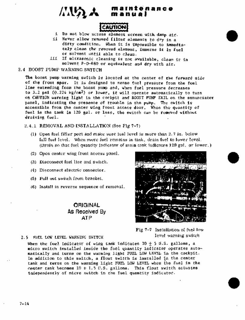
/:~5 ~t m a ~´•n Z a a a a amanual
CAUTION
i Do not blow across element screen witk damp air.ii Never allow removed filter elements to dry in a
dirty condition. When it is impossible to ~nmedia-
tely clean the removed element, immerse it in fuelor solvent until able to clean.
iii If ultrasonic. cleaning is not available, clean it insolvent P-D-680 or equivalent and dry with air.
2.4 BOOST PUMP WARNING SWITCH
The boost pump warning switch is located at the center of the forward sideof the front spar, It is designed to sense fuel pressure from the fuel
line extending from the boost pump and, when fuel pressure decreases
to 3.2 psi (0.224 kg/cm2) or lower, it will operate automatically to turn
on CAUTION warning light in the cockpit and BOOST PUMP FAIL on the annunciator
panel, indicating the presence of trouble in the pump. The switch is
accessible from the center wing front access door. When the quantity of
fuel in the tank is 120 gal, or less, the switch can be removed without
draining fuel.
2. 4. 1 REMOVAL AND INSTALLATION (See Fig 7-7)
(1) Open fuel filler port and make sure fuel level is more than 2. 7 in. below
full fuel level. When more fuel remains in tank, drain fuel to lower ].evel.
(Drain so that fuel’ quantity indicator of main tank indicates 120 gal, or lower.
(2) Open center wing front access panel.
(3) Disconnect fuel line and switch.
(4) Disconnect electric connector.
(5) Pull out switch from bracket.
(6) Install in reverse sequence of removal.
ORIGINAL
As Received ByAT P
Fig 7-7 Installation of fuel low
2.5 FUEL LOW LEVEL WARNING SWZTCHlevel warming switch
When the fuel indicator of wing tank indicates 30 f 5 U.S. gallons, a
micro switch installed inside the fuel quantity indicator operates auto-
matically and turns on the warning light FUEL LOW LEVEL in the cockpit.In addition to this switch, a float switch is installed inthe center
tank and turns on the warning light FUEL LOW LEVEL when ~he fuel in the
center tank becomes 10 f 1.5 U.S. gallons.. This float switch actuates
independently of micro switch in the fuel quantity indicator;
7-14

´•I´•´• I;: :ir i:.
POO ~bia i PO f: ..PO ~i iii~ ~ia,
APJLi, ’6HECIi;L
(1)(2) fiiei in ~wing t8nk;intil warning light F’I~L i;dFj L~VEL
(3) When the t\ramihg light illtrmi~ihtesi in the.tank sfioulii b~ 30f5U.S. galldns, excluding fuel;
(4) Inspe~tion of switch in the cBnte~tank is withoutoperating the fuel ~uanfity indicator. fu~i (ceihtertank andi LH and R~I outboaid tanks) after illumination of warning lightshould be 33+5 U.S. gallans;
2;6 MANIFOLD
The manifbld cods´•isting of adapter.and body is located $lightly to the left
from the centeroi the fr6izt ~Side of the center fbel tank. Fuel comingfrom two boost pumps in the center tank collects in this manifold, and
is then fed to both engilies. The adapter is attached to the front spar
of the center fuel tank. The elbow on which the fuel shutoff valve is
inst’alled is mounted on the adapter.
2.6.1 REMOVAL AND INSTALLATION (See Fig 7-8)
(1) Drain integral’ tank.
(2) Remove center tank upper LH access panel.
(3) Disconnect fuel hose which connects boost pumpto manifold, at the´•
the tee joint.
(4) Remove pressdre sensing hose connecting to boost pump warning switch.
(5) Remove center wing front access panel.
(6) Remove fuel shutoff valve~and elbow.
(7) Cut lock wire and remove ten attaching bolts for manifold.
(8) Take manifold:out through~center tank upper access door.
(9) Install in reverse sequence of removal.
3. FUEL VENT SYSTEM’
The fuel vent system is providedfor the proper ´•aajustn;entof fuel tank
inner pressure unherev´•ery condition. Integral~tanks are interconnected
by vent holes and vent lines ´•.nd air ´•in the tanks are freely open to each
other; Vent holes are pr.ovided between the center ta~k andoutboard tanks.
The vent valves are located on the’ top of´•the center tank and outboard
tanks. Vent valves connect the outboard tank valves to the center tank
vent valve and are led to the flush type vent‘ outlet on the lower surface
of wing between spars,.near the wing tip..: This vent outlet is designedto provide slight pressure’ to fuel tanks, preventing ~obstruction by icing.
The vent valveis designedto operate.during climb or descent of:the aircraft
by corresponding float-movement~to the the fuel level. Two relief
valves are provided ~on thecenter fuel tankwhich are connected to the vent
line. These valves are designed´• to openlwhen the pressurereaches and/or
exceeds 2.0 psi~ (0.14 k.g/cm2j ´•in-’the tank to allow the air and/or fuel into
the vent line to prevent pressure builaup´•.in the tanks.
_li---´•´•´•-’’;----.-I 7-15

ra a i at a .n a a a 8m a a a d(
i.4 ~-5
o~q.4 2
3
I. Check valve 3. Elbow
2. Adapter 4. "0" ring
Fig 7 8 Installation of manifold
3
~,STT=
I;
8i. Vent valve
i. Gasket
3. Vent valve body
4. Ventline
Fig 7 9 Center tank vent valve
7-16
C x iit~ a n nrii i
i;´•´• a I´•
in a I a ~e:~.rh a its ci~
$.i TANK
of the part of th~ center It is designed to close the vent byaThe%enter tank irent valve i´• fl’oat-type andlocated at the access door on the top
flbat when the fuel ievel rises,
3.~.i REMOVAL AND I~STALLATION (Se~ Fig 7-9)
(1) D’~gin the integral tank.
(2) i2eli~oire the L. k. and R.1H. aces:s panel on the top of the center wing;
(3) Ri~nioire fd~r iyhich attach l;h vent valve cov~r and v~nt valve body,and discorine.ct the vent lines leading to the L.H. and R.H. outboard tanks
and also le&ding to the main vent line.
(4) Cut ~the lock i~iire from thevalve body and remove the valve with
a gasitet froni the valve body.
(5)- Install in ~ireverse Sequence of re~sval.
Takecare of thi~’following items when iilstalling.(a) InSrallation torque of the vent valve to the body is 150
to 250’in-lbs. (17~1 to286 kg-cm).(b) Installation torque for the screws of the access dooris
30 to 35 in-Llbs.(.34 to~40kg-cm).3.2 OUTBOARD TANK VENT VALVE
The outboard tank vent valve is installed on the top of the~ outboard tank and
the same~one as the center tank vent valve. It is easj.ly accessible throughthe access door on the top of thetank.
3. 2. 1 REMOVAL AND INSTALLATION (Se Fig 7-10)
To remove and install the vent valve, proceed´• as follows.
(1) Open the acces’s panel (W. STA1250h´•W;STA1600) on the top of the outboard tank.
(2) Disconnect the vent lines.
(3) Remove four bolts which secure the valve and fitting;
(4) Remove the valve and fitting from the bracket and remove the valve with "O"
ring from t~e fitting.(5) Install in reverse sequence of removal. Installation torque of
the valve’ to screw into the.fitting is 390 to~ 430 in-lbs. (445to 491-kg-cm)
3. 3 -OUTER TANK VENT VALVE (See Fig 7-11)
The- outer; tank vent valve is a ball-type valve installed on the top of the~ outer
It is designed to close the vent by a ball-type float when the fuellevel rises.
It is easily. accessible.through the .ccess door on the top of the tank.
3. 3. 1 REMOVAL AND INSTALLATION
To remove dr install. the~ vent valve, ´•perform the following procedures with
aircraft power off.
(1) Drainthe outer tank.
7-17

m a a a a Ime~nte?lano8
2
~nnC
i.
’5
O
1. Ventline
2. Vent valve fitting
3. Bracket
4. Attaching bolt
5. Washer6 lcl
6. Vent valve
ii7. "0" ring
Fig 7-10 Outboard tank vent valve
(2)(3) Remove dip stickand filler port cap.iBpen filler port cover at W,STA 34;40..
(4) Loosen hose clamp at fuel filler’ portand disconnect vent line.
(5) Cut safety wires of 14 bolts attachingVent valve, remove bolts, and remove
vent valve with vent line and connector hose.
(6) Install in reverse sequence of removal.
1~
2
i. Vent valve 3
2. ’~0" ring
3. Ventline
Fig 7-11 Outer tank vent valve assembly
7-18

B8a~ qe il~n t e.~l ~ii h eet~i a Irs u ri 81
t~ gpa~ df Sectib~ ii7~boara o~ frbi41
w;.s;ir~i, ~i; S~A ´•ig´•gg ~i, ~i an iitegk´•ai~ f~el Bnic.ta~k is thi;e~ se´•ctions, sei~ter: t~ni(, it; i-I ’dutbd$~d taiiic ai~d
tank ioy bdikhedds at ~iT; 586. Eac~’’’h sadtii~n is iiiterdoj3rie~ted
by ve~t Foi’ repair of integral t~i’iiii; see chaljter 2 Sectioi~ 6 df this
ms~uai
WOTE
kccess panel install~d in correct position.Incbrredt instdllation ma)i cause ´•fuel leakage.
center access Fuel filler port (’kl)
Center\Yin tankOutboard tank
door access dooraccess door
Filler port Filler port ("2)
III III~
-----J[L-- -L- --)IL---
Left outboard tank Center tank ~ht outhaatg tank
I1950 1660 1250’ 920 580 194 0 194 580 920 1250 1600 1950
(W. STA)
Access dqor~ ~(Rem oval)
"1 Aircraft S/N 652SA, 661SA; B97SAthru 724SA
"2Airdraft S/N 725SA alid´•subsequent
Fig 7-12 I~ocation of integral´•tank access door
7-19
c~-’Csk M a i nt e.n a a a 8
m a a a a
5. TIP: ANK FiTEL SYSTEM
Th;e tip tank fuel syZ;tem consists of two 93 U.S. gallon tip tanks located
on the wing tips, pressure air line for pressure supplyof fuel, air
shutoff valve, air regulator, check valve, vent disc, fuel line
for transferring fuel to c~nter tanks, fuel shutoff valve, and fuel level
control valve. The fdel in tip tanks is transferred to.the center tank
automatically by air pressure in accordance with the’fuel level. of the
center fuel tank. The screen and orifice are installed in the line for
air conditioning system.
5.1 FUEL TRANSFER SYSTEM
Close the TRANS CONT circuit breaker and place the left or right TRANSFER
switch to the TIP MANUAi; position. When the fuel quantity remaining in
each tank is over 3 gallons, the pressured air taken from the air condi-
tioning system flows through the air shutoff valve and the air pressure
regulator where it is regulated to 4 to 5.5 psi (0.28 to 0.39 kg/cm2),thus adding air pressure to the tip tanks. The pressurized fuel from
each tip tank passes through a fuel line, strainer, fuel shutoff valve
and joins at the center main tank inflow port. The fuel level control
valve acts when the fuel level in the center tank drops below the opera-
ting level of the fuel level control valve and allows fuel to flow into
the tank. The valve closes when the fuel level rises.over the operatinglevel. The fuel low level switch, in each tip tank, operates when the
operates the TIP LOW LEVEL annunciator light on the lower enginetip tank fuel level is 3 gallons or less. This low level switch
instrument panel and also energizes the air pressure shutoff valve to
the closedposition.
5.2 AIR SHUTOFF VALVE (See Fig 7-13)
The air shutoff valve, which is solenoid-operated, is designed to operatein 0.05 second.. It is located in the wing-fuselage fillet on the tip of
the top of the right-hand side of the fuselage. When’both the right and
left: low level switches of the tip tanks operate, thevalve automaticallycloses.
5.2.1 REMOVAL AND INSTALLATION
(1) Remove center wing front access panel.
(2) Disconnect electric connector.
(3) Disconnect air lines on both sides of shutoff valve and remove
the valve.
(4) Install in reverse sequence of removal.
5.3 AIR PRESSURE REGULATOR
The pressure regulator is located on the same bracket as´•the air shutoff
valve.
7-20

si’9, :bti LiP C.il~lt Q iii! i~i8~C ciSL~e os ~1 a I
~hls i$ the ~s the shutoff valve u’sed in the aiain fuel feed
sijitch is p~aced to ~IANZjAL Position, The ~alve is cios~ds~stemi ~he vaiv@ is bgened iniheli circui~ breaiter TIliWS ‘CO~T i~ ~losed aild
when the ~witch is placed to the OFF position, This ~alve is accessible
thrdtiBh the bccess door ~n the wing leading edge lower surface iriboard of
the ~celle i
5.3.1 RE~MOVAL AND INSTALLATION (See Fig 7-13)
~o Lemove and install the air pressure regulator, proceed as follows,
(1) Remove c~nterwing front access panel,
(2) Disconnect lines at both ends of the regulator and disconnect drain line,
(3) Remove three screws and spacers, and regulator,
(4) Install in reverse sequence of removal,
5.4 FUEL SHUTOFF
This valve´•is the s~me’as th.g.fuel shutoff iraliie used in the main fuel feed
sys fem, The iralve is opened when circuit breaker FUEL TRANSFER CONT is closed
and FUEL TRANSFER switch is placed to AUTO (when fuel remains in tip tank)oi- TIP MANUAL, The vdlve is closed when’the switch is placed to the OFF position,
This valve ~s accessible through tile access door on thewingleadingedge lowersurface inboardof the nac~lle.
5.4.1 REMOVALAND INSTALLATION (See Fig 7-14)
(1) Remove access door on’wing leading edge lower surfac´•e inboard of
the engine nacell~.
(2) Disconnect electricconnector and bonding jumper,
(3) Disconnect fuel lines at both sides of shutoff valve,
(4) Remove attaching bolts for the:valve and take the valve.outof bracket,
(5) Install in reverse sequence of removal,
ii
s: ~:S´•:’C3
Fig~ 7-13 Installation of aik´• shutoff valve Fig 7-14, -Installation of fuel
and air pressureregulator shutoff vrilve
ORIGINAL7-21
As Received ByAT P

m a Int a a a a a a
m a a a al
5. 5 FUEL LEVEL CONTROL VALVE
The fuel level control valve, located ~in the center tank, consists of a float, pilotvalve, and diaphragm.The pilot valve is interlocked with the float. The diaphragm chamber, the top of
which constitutes the wall, is connected to the pilot valve chamber. The bottom,formed by the diaphragm, is pl;ovided with a small hole in the center. The fuel
outlet is closed by the seal of the diaphragm.
5. 5. 1 REMOVAL AND INSTALLATION (See Fig. 7-15)
To remove the fuel level controlvalve, proceed as follows:
(1) Drain fuel system.
(2) Open access door on top of right-hand center tank.
(3) Disconnect fuel line by removing four bolts and take out the valve.
(4) Install in reverse sequence of remo3al.
sjrsm
6
O
I:~
1. Fuel control valve 3. Adapter 5. Seal 7. Diaphragm chamber
2. 0- ring 4. ~Pilot 6. Float 8. Diaphragm
Fig. 7 15 Installation of fuel control valve
.Take care of the following items´• when installing.
(a) Installation torque of four:bolts connecting the fuel level control valve is
10 N 14 in-lbs. (11.4 to ´•16.0 kg-cm).
(b) Install O-ring, lubricating with petrolatum (VV-P-236).
7-22

mPintensheitbo a a,~b 21
j.6 (~ee jFi~ ii16)
~lie Zelilei at gbove 7 psi(i).49 kg/cn:) of tanii i nn.er p~essure to let
pr´•essure dht fiito the’atm~sphere, af;d at -O. ?y -´•1 .r2~1:lsi.i7-0.;05--to suip~iy oiitbi~e ´•air iiito the tanii. The \ialve
is sci´•eiired in bri the taiik ´•waij Bndl ´•i,ermitsremoval and iristallation tlirectly i‘lctrr~ outside;Installation ~brque ie 300- 4(10 :id-l 1,9 i346~ 46 i
kg- ctn).
5. 7
The tip taizks are made of ailuminum alioy~and each t~nk is installed to the wing tipwith two brackets. Each tank’ is divided Fig. 7 16 Sniffle valve
into three parts: front, center and rear.
These three parts are connected to ohe another with 20bolts gt each seam.
There is a vacant space in the ´•tip of the front and rear .to prevent tank
d~magefrom lit~hta2ng strike.
Two~fins are provided on the tank for improved flying characteristics. An
access hole is provided on.the top of the front section. Ar the center of
the tip tank, the fuel quantity galge tank unit is installed, by which
fuel quantity is’transmitted to the dual pointer indicator in the cockpit,
indicating fuel quantity of-the tank. I
Tip light and sniffle valve are located on outer side of each tip tank.
The pressure air line and fuel feed line are connected with hoses to the
counterpart lines on the airframe. The area between the tip tank and the
wing is faired with fill’ets. The drain valve is located on the bottom
of the tank. On of the.tankis a low-level switch,which automatically operates at 3~gallons of remaining fuelto close the
air shutoff valve.
Onthe top at the rear.of the´•tank is a fuel filler port.
Connection’and separation of the three sections of the tip tank can be
accomplished through access doors on the´•top of each section.
P11OTE
When work’ is done in ~the tank,´•´• specialattention must be paid not to apply
~!´•st’rong force on tubing’~and conduit, et´•c.
7-23

c~s It ni $I a pi f 8 Ilo a n e
mbnu’a(
5.7.1 REMOVAL AND INSTALLATIONTo remove the tip tank, proceed as follows.
(1) Push sniffle valve to relieve pressure inside the system.
1~ R M I P1 G
i High pressure may be present in the systemand, therefore, be sure to relieve pressure ORIGINALprior to tank removal.
As Received Byii Do not stand directly in front of the sniffle
AT Pvalve when releasing pressure, due to
possible.fuel ejection through the valve.
u;´•:
Fig. 7- 17 Remove fillet and wire Fig. 7 18 Pull out air pressure line
at terminal block and fuel transfer line
(2) Drain fuel.
(3) Remove fillet.
(4) Disconnect electric wires at terminal block, see Fig 7-17.
(5) Loosen hose clamps of pressure air line and fuel transfer line, and
then pull hoses off, see Pig 7-18.
(6) Remove three attaching bolts and then remove tip tank carefully.
(7) Install in reverse sequence of removal.
5.7.2 NOTICE TO INSTALL TIP TANK
(1) Tighten hand-tight the bolts which connect wing side rear fitting to
tip tank rear bracket after applying MIL-G-21164 grease on the bolt
shanki ´•Apply lock wire to prevent bolt from rotation.
(2) Apply MIL-G21164 grease on the bolt shank. Make sure that the clearance
between wing side fitting and tip tank bracket is less than 0.01 in.
(0.25.mm), and then apply 270 to 300 in-lbs (309 to 343.kg-cm) torque.
(3) Make sure that the clearance between wing side rear fitting and tiptank rear bracket is more than 0.002 in. (0.05 mm) after installation,see Pig 7-19.
(4) Installation torque of hose clamps used in pressure air line and fuel
transfer line is 25 in-lbs (28.8 kg-cm). Check the bolts for torqueafter installation or flight, and retighten if necessary.
7-24

a n iEi
~i i~ a B
M’eaSure tkiis ’cl’earance
6. 002 iri. NIin. Ih-r i: Edit ~MS20006-12)
(n.i) mm) IIU~U
jnstallation torque value
1 till ~1 1.60 rv 190 in-lbs (183 to 217 kg-cm)
2. ~iirasher (M~20002 C6)
2\ ~fT 1TTT’HTT~ 3. Sealing washer (2230-6)
3, hfil II 1 4. Spacer (022A-48454)a’ 5. Fitting-wing side (010A-12137)
4~ I r 6. Bracket-tank side (016A-48204)7 j; O-ring
Fig. 7 19 ´•Details of tip tank rear jbin!
Wing tip fittingApply grease M1L-C-21164
~n bolt shank.
Torque 270~300 in-lbs
(309 to 343 kg-cm)
One washer Two washers
Clearance less than 0. 01 in. (0.25 mm)
FRONT SPAR SIDE
Apply grease
Approx.SOO IMIZ-G-21164
on- bolt shank.Apply lock wire to
prevent bolt from
rotation. sf~ I LHand tight
Twist lock wire here
REAR SPAR SIDE
7-25

c~s ?e m a Int a a a.n a a
m a a a a I
5.7.3 TIP TANK LEAK TEST
When a part in the tip tank is replaced, work is done ´•in the tiptank or strobe light is replaced, perform the following leak test
and make sure of no leak at the relative point.
5.7.3.1 When tip tank is not installed on the airplane:
(1) Plug fuel transfer line.
(2) Connect pressure source- with pressure air line.
(3) Clog sniffle valve with tape.(4) Apply air pressure of 7.5 psi +0.05/-0.0 on the tank.
(5) Check for leaks.
5.7.3.2 When tip tank is installed on the airplane:
(1) Remove the access panel of the center wing leading edge,disconnect tip tank pressure air line at tee and connect
pressure source with it.
5.8 OPERATIONAL CHECK AFTER TIP TANK INSTALLATION
Supply fuel and accomplish operational check of the system in accordance
with the following procedures after removal and installation of tip tank.
(1) Close circuit breaker TIP\FUEL QTY and make sure that the tip tank
fuel quantity indicator points correctly.
(2) Close circuit breaker NAV LIGHT and turn the navigation light switch
NAV in the overhead switch panel to ON. Make sure that the wing tip
light becomes illuminated.
(3) Close circuit breaker STROBE LIGHT and turn strobe light switch STROBE
to ON. See that the strobe light becomes illuminated and goes out.
(4)- Start the engine and close circuit breaker FUEL TRANSFER CONT and
place FUEL TRANSFER switch to TIP MANUAL: Make sure that fuel is
transferred normally from the tip tank, in accordance with indication
on fuel quantity indicator.
(5) Inspect that pressure air line and joint of fuel linebetween tank
and airframe have no leaks.
7-26

s~k e’A i~i.~.i i
$L aP iE~iD
5.9 OP$RA~ION Cit’Ei~GK Tfij TANK E;i~ti, Ti~ANSPEII
Gjhen naiiijo’r p~rtS iii this system (f~i.el cbntrdl valve and low level switch)a~e Chec’k ~he fuel transfer system as follows:
(i) Fe’ea 30 gallons of fuel fb eaCh LHand tip tank.
(2) ’~pen C~ntei- ‘tank RH access’dbor and feed abo~it 47 galloi~s 05 fuel.
~uei level at this time is approximately 2.7 inches rmn) from the
Surface of the access door.
(3) Disconnect tip tank air line at the air source side of the air shutoff valirej coiihect to grdund air sou?ce and apply 30 psi (2.1 kg/cmof air to the tip tank air pressure system.
,(4) Close TRANS CONT ciircuit breaker and place the TRANSFER switch to
the TIP MANUAL POSITION.
(5) Make su~e fuel letrelof center tank rises ~ue to transfer from tiptank and ~jhen the level reaches approximately 1.85 inch (47 mm) from
the Surface of the center tank RH access’dodr, fuel eransfer Stops.
(6) Operate boost pump and take out fuel rrom the center tank.
(7) Make sure rhat´•wh~en the fue~´•levelof center tank becomes approxi-mately’2i0 inches’(51 rmn) fuel´•transfer starts again.
(8) Place TRANSFER CONT switch to AUTO position and repeat steps (5)thru (7) a6ove.
(9) To operate LH andRH tip tank lowlevel switches, continue to transfer
fuel until the airshutoff valvefor tip tank~pressure air line (fuelquantity ~indicator points at ZERO gallons) closes. ~While transferring,check difference between LH and RH fuel quantity indicators for ex-
cessive fuel transfer imbalance.
(10) Place the TRANSFER switch to the OFF position and open the TRANS
CONTandBOOST PUMP.circuit breakers. I
(11) Check the system for~fuel leaks.
(12) Install access panel after checking thatno foreign substanceismixed
in center rank fuel. ground air source a~id connect pressure
air l;inefor t´•ip´•tank-.
7-27
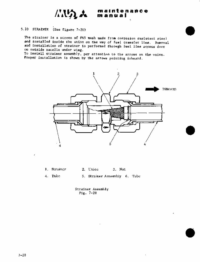
ra a at a a a a a a
m a a a a I
5.10 STRAINER (See Figure 7-20)
The strainer is a screen of ~65 mesh made from corrosion resistant steeland installed inside the union on the way of fuel transfer line. Removaland installation of strainer is performed through fuel line access dooron outside nacelle under wing.To install strainer assembly, pay attention to the arrows on the union.
Proper installation is shown by the arrows pointing inboard.
1 2 3
IINBOARD
5 4
i. Strainer 2. Union 3. Nut
4. Tube 5. Strainer Assembly 6. Tube
Strainer AssemblyFig. 7-20
7-28
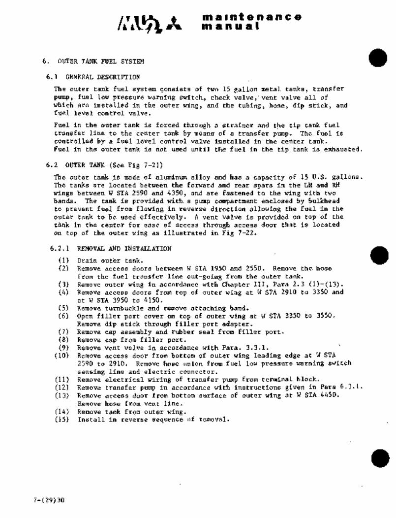
c~s III a s a f 8 11 a a a 8
BtO as a a
6. OUTER TANK FUEL SYSTEM
6.1 GENERAL DESCRIPTION
The outer tank fuel system consists of two 15 gallon metal tanks, transfer
pump, fuel low pressure warning switch, check valve,’vent valve all of
which are installed in the outer wing, and the tubing, ´•hose, dip stick, and
fuel level control valve.
Fuel in the outer tank is forced through a strainer and the tip tank fueltransfer line to the center tank by means of a transfer pump. The fuel is
controlled by a fuel level control valve installed in the center tank.
Fuel in the outer tank is not-used until the fuel in the tip tank is exhausted.
6.2 OUTER TANK (See Fig 7-21)
The outer tank is made of aluminum alloy and has a capacity of 15 U.S. gallons.The tanks are located between´•tEie forward and rear spars in the LH and RH
wings´• between W STA 2590 and 4350, and are fastened to the wing with two
bands. The tank is provided with. a p~rmp compartment enclosedby bulkhead
to prevent fuel from flowing in reverse direction allowing the fuel in the
outer tank to be used effectively. A vent valve is provided on top of the
t;8nlo in the center for‘ ease of access through- access door that is located
on top of the outer wing as´• illustrated in Fig 7-22.
6.2.1 REMOVAL AND´•INSTALLATION
(1) Drain out~rtank.
(2) Remove access doors between W STA 1950 and 2550, Remove the hose
from the fuel transfer line out-going from the oute’r tank.
(3) Remove outer wing in accordance with Chapter IIS, Para 2.3 (1)-(13).(4) Remove access doors from top of outer wing at W STA 2910 to 3350 and
at W STA 3950to 4150.
(5) Remove tun;buckle and remove attaching band.
(6) Open filler port ~overon top of outer wing at W STA 3350 to 3550.
Remove dip stick through filler port adapter.(7) Remove cap assembly and rubber seal from filler polt.(8) Remo´•re cap from filler port.(9) Remove vent valve in accordance with Para. 3.3.1.
(10) Remove access door from bottom of ´•outer wing leading edge’at W STA
2590 to 2910. Remove hdse union from fuel low pressure warning switch
sensing line andelectric connector.
(11) Remove electrical wiring of transfer pump from terminal block.
(12) Remove transfer ´•pump in accordance with instructions given In Para 6.3.1.
(13)~ Remove access door from~bottom surfaceof outerwing at W STA 4450.
Remove hose from vent line.
(14) Remove tank from out’er wing.(15) Install in reverse sequence of removal.
7-(29)30

I~ b wu ~4% h~ e.I,r a ~a i~ ~si I
ioi ik~iel warni;i~iz~ ii. Vent iralve
z 12. St~aiherI::
13
i. i~ueltransferline:-1
i: Outer tank
3. Bbndingwire I/
4. AttBching b~rid
5. Dip Stick
10 96. Filler Port
7. Drainline
3. V‘entlilie
9. Transfer pump Fig. 7-2i Outer tank
Fuel filler
port cover
Tank fastening band
access doorTank fastening band ’ai~dvent valve access door
Vent line access
door
I II 1´• II/
1950 1~ 2690 1 2910 saaol 3 9 6 0 1 4 a’5 0
9550 4150.’ 4650
Engine upperaccess door I Transfer’.Dwnr, access´•door
Fuel low pressure warning switch ac~cess door
´•Note~: ’1’.’ ’rh‘e, figure shows~wingupper surface
2. OiA~ccess door on wing upper- surface
:i.~ C~;AccesS door on wing lower surface
Fig. 7-22 Outer tank access door
(PWIGB ~BAC As
RECEIVED BY7-31
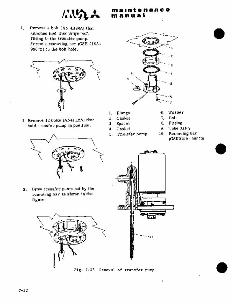
clr~zat a II to t a a a a a a
t9a a a a a I
1. Remove a bolt (IAN 4Ha4A) that
attaches fuel discharge port
fitting to the transfer pump.
Screw a removing bar (GSE 016A-
99072) in the bolt hole.
C~
Bs1. Flange 6. Washer
2. Remove 12 bolts (AN4H12A) that 2. .Gasket 7. Bolt
hold transfer pump in position.3. Spacer 8; Fitting
4. Gasket 9. Tube ass’y
5. Transfer pump 10. Removing bar
(GSE016A-99072)
3. Draw transfer pump out by the
removing bar as shown in the
figure.
I ~lo
Fig. 7-23 Removal of transfer pump
7-32

c~wa~a se a o~i B n
~Ea
ijij ;TRANSFER ~PUMP
a A cdh’staat speBd, subm~lgea t3pi~transferEleCt;rii~ ~s thi! tank. Th’e pump hs´• rat~d at:
Ci t~ 608 PijH´•i~i´• i.’t’b S;j ~oi (~;i4 to b.5 kg/cm2j di
pressure; 28 V6C a~id 3.75 Aihi>s; maximum;
a~rcraftiA conbtent ~ea, aenerifii~al, jubrde~god tyt~e tranSfer purop iAiLbbihe inodel
1612-3) isII
of.fla;~-, 6.to~:d ps´•i (0.42 to 2,1 iiglcmiihe i~ ratd at O to b25 PPHi~ t,nk.
of pressure, 28 VD6 and
6.3.1 REMOVAL AND INSTALLAillION (See Fig 7-23)
(1) Place FUEL TRANSFER mitcfL on LK intrument panel to OFF, open TRANS
CONT circuit breaker, and turn aircfaft power OFF.
(2~ Removb access door froin- bottom of‘outer tank at W STA 2590 to 2910,
(3) Drain outer tank.
(4) R~emove gccess door f~om boftoli~ of outer tank leading edge at W STA
2590 to 2910.
(5j Reinoire electric terminal from transfer p~rmp, E’ig 7-24.
(6) RBnioi~e a bolt that attsickes fuel discharge port fitting to the transfer
pump. Screw a removing bar ~GSE 016A-99072) in the bolt hole. Installation
tor~ue of.theboltis- 75 to 85 in-lbs (86,4to 97..9.kg-cm).(j) Cut safety wires of bolts that hold transfer pump in position, ´•Remove
bolts. Installation torqu~ of the bolts is 25 to 35 in-lbs (28.8 to 40.3 kg-cm),(8) Draw tranSferpump out the removing bar, see-Fig 7;25,
(9) I~iemove trsinsfer~´•pump´• ...drai;n- valve Installation torque of the valve
is i5-.t-a1.35 in-lbs (28.8 to 40,3‘kgicmj.,(10) Remove hose fitting from fuel discharge port, Remove transfer pump~
(11) Install in reverse sequence of removal,
149
ORIGINAL
As Received ByAT P I
Fig. 7-24 Remove electric terminal Pig. 7-25 Remove tlansferpump
from transfer pump
NOTE
Wl~c:ii Ic:il,~tit;lllina ti´•ansfer Ii~lmp, he;´•ic-l the nc?cili nf
fuel discharge fitting forward,
7-33
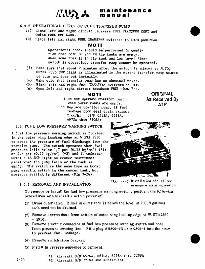
li~ a c Pa t a bP a ii a
POI ahuas
6.3. 2 Oj?ERAT~ONAL CHECK OF FUEL TRANSFER PUMP
(1) Close left and right circuit ~reakers FUEL TRANSFER CONT and6iPTER FUEL EMP WARN.
(2) Place left and right FUEL TRANSFER switches to AUTO position.
NOTIE
Operational check should be~performed in condi-
tion that both LH and RH tip tanks are empty.When some fuel is in tip tank and low level float
switch is operating, transfer pump cannot be operated.
(3) ~lake sure that about 2 minutes after the switch is placed to AUTO,OUTER FUEL EMP light is illuminated in the moment transfer pump starts
to turn and goes out instantly.(4) Make sure that transfer pump has no abnormal noise.
(5) Place left and right FUEL TRANSFER switches _o OFF.
(6) Open left an~d right circuit breakers FUEL TRANSFER.
rY OIE ORIGINALi Do not operate transfer pump As Received By
when outer tanks are empty. AT Pii Replace transfer pump, if fuel
leakage from seal drain exceeds
2 cc/hr. (S/N 652SA, 661SA,697SA thru 720SA)
6.4 FUEL LOW PRESSURE WARNING SWITCH
A fuel low pressure warning switch is providedin the outer wing Leading edge at W STA 2950
to sense the pressure of fuel discharge from the
transfer pump. The switch operates when fuel
pressure falls below 1.7 psi (0.12 kg/cm2) ("1)or 2.5 psi (0.17 kg/cm2) (*2) and illuminates
OUTER FUEL EMP light on center instrument
panel when the pump fails or the tank is
empty. The switch is the same type as boost
prrmp warning switch in the center tank, but
pressure setting is different (Fig 7-26). 1
Fig. 7-26 Installation of fuel low6. 4. 1 REMOVAL AND INSTALLATION
pressure warning switch
To remove or install the fuel low pressure warning switch, perform the following
procedures with aircraft electric power off.
(1) Drain outer tank. If fuel in outer tank is below the level of 7 U.S gallons,tank need not be drained;
(2) Remove access door from bottom of outer wing leading edge at W. STA2590
N 2910.
(3) Remove electric connector of fuel low pressure warning switch and hose
from pressure sensing line. Fit a plug AN806-4D or AN806-4 into the hose
to prevent fuel leakage.
(4) Remove switch from bracket.
(5) Install in reverse sequence of removal.
*1 Aircraft S/N 652SA, 661SA, 697SAthru 720SA
7-34 *2 Aircraft S/N 721SA and subsequent_

m ii ta U a s
tank ~s with ~uel qii;antitfi indi~8toi´• tank unit; ~nste8ci; a d’ipsti~k is~ iis~d for cheilking fuel Ievel.
i. GaugeI/
Insert bar O into
2. Bar gauge as shown in
3. Ciarrip ass’y
4. Cap3 Datum line
5: Seal
Rdapter
21 Put the bar inserted into
,I the gauge on the filler port
as shown:in the figure and
measure fuel quantityrom the datum line.
Fig. 7-27 How tr,;se dip stick
6.6 .OPERATIONAL CHECK OFOUTER TANK FUEL TRANSFER SYSTE~:
Operational checkof outer tarik.fuel transfer~systemis accomplishedas follows.´•
(1) Fill LH and RIF outer tank with 10 U.S. gallons of fuel each.
(2) Open’RH access door of center ta~ik. Refuel the tank-to a level of
approximately 2 in. (50 mm) below access doot.
(3) Turn aircraft electric power ON. Close circuit breaker FUEL TRANS
GONT and OUTER FUEL´•EMP WARN.
(4) Place LH- and RH FUEL TRANSFER switch to AUTO.
MOTE
Operational checkshould be´•performed in
condition that both LH and.RH tip tanks
are empty. When’~some fuel. is in- tip:tank-arnd c.o~ Plo:a~t:’: switch Ps: opeirati;ig,tqans:fer punhp’’~can:riot be ~operated.
’:Ma~e suri~].that abou´•t. 2´•´•minutes gft~er the.switch:i’s ~placed.’to AUTO,OUTER FUEL EMP´•~light’ is.~illuminated at the.mordent transfer pump starts
to turn and goes .out instantly.(5) Bleedfuel from’center tank at a rate of approximately 2.4 gal/min.(6) LH and RiT OUTE~´•FUEL EMP lights are illuminated, then place FUEL
TRANSFER switches to OFF. Stop draining center tank.
(7) Open‘circuit breaker’FUEL TRANSFE~.CONT and OUTER FUEL EMP WARN and
turn aircraft powerOFF.(8) Ensure thatLH and RHouter tanks gre empty, seeing through filler ports.
7-35

C1~5 ma~,ateaancem a a a a I
NOTE
i If EMPTY light is not momentarilyilluminated with FUEL TRANSFER
switch in AUTO, it is usually due
to poor contact or failure of lamp.
ii If empty light does not go off and
remains on, it is usually due to
fuel low pressure warning switch
being preset at a higher operatingpoint. Replace the switch.
6.7 STRAINER
This is the same strainer as the one for tip tank installed on the way of
tip tank fuel transfer line (See Para. 5.10). The strainer is installed
on the way.of outer tank fuel transfer line and can be removed or installed
through the engine upper access door on wing. The strainer assembly should
be installed so that the arrows on the union point to the airplaine center
line. .Installation torque to the boss is 390 to 430 in-lbs. (446 to 491
kg/cm) (Fig. 7-20).
7. FUEL QUANTITY INDICATING SYSTEM
The fuel quantity indicators in the cockpit, indicating in U.S. gallons,indicate the quantity of fuel in the fuel tanks in the wing´•and in the tiptanks. For this purpose, capacitor-type tank unitsare employed. For
the quantity of fuel in the wing tanks, one fuel quantity indicato~ is
employed, which indicates the total quantity of fuel in the tanks. The
quantity of fuel in the tip tanks,however, is indicated by a dual indi-
cator. When the quantity of fuel remaining in the fuel tank in the winghas decreased to 30 f 5 gallons, the warning light FUEL LOW LEVEL illuminates.
For adjusting fuel quantity indicator, see Chapter X, section 5.
7.1 FUEL QUANTITY INDICATOR
The fuel quantity indicators a~e arranged on the front instrument panel in the
cockpit.
7. 2 FUEL QUANTITY TANK UNITS
In this aircraft, five capacitor-type fuel quantity tank units are
employed: one in the center tank, one each in outboard tanks, and one
in each tip tank. Each tank unit is installed with bolts to.~a bracket
attached to the tankrib..
7.2.1 REMOVAL AND INSTALLATION OF CENTER TANK UNIT
(F~g. 7-28)
(1)´• Drain integral tank.
(2) Remove center tank upper R.H and center access panels.
7-36

maintenancemanual
(3) Through RH access panel opening, disconnect vent valve lines from the
vent valve/panel assembly, and disconnect electric connector.
(4) Remove bolts attaching tank unit to brd~ket through center tank
upper access panel, and remove tank unit.
(5) Install in reverse sequence of removal.
NOTE
When removing unit from tank, caution
should be exercised not to damageinner wall of tank.
7.2.2 REMOVAL AM) INSTALLATION OF OUTBOARD TANK UNIT
(1) Drain integral tank.
(2) Open upper access door W STA 1250 to 1600 of outboard tank.
(3) Remove electric connector from tank unit.
(4) Remove bolts which attach tank unit, and take out tank unit throughaccess door.
(5) Install in reverse sequence of removal. Installation torque of
access door attaching screws is 30 to 35 in’lbs (35 to 40 kg-cm).
7.2.3 REMOVAL AND INSTALLATION OF TIP TANK UNIT (See Fig 7-29~
(1) Drain tip tank.
(2) Remove tip tank upper center access door.
(3) Disconnect the electric connections from tank unit and remove bolts
which attach tank unit and remove the unit through access door.
(4) Install in reverse sequence of removal.
NOTs
When work is done in the tank, specialattention must be paid not to applystrong force ontubing, conduit, etc.
!:i: r
:ZB ´•:i
s~: i;
´•´•r~
iili,
Fig. 7-28 Center tank fuel quantity Pig. 7-29 Tip tank fuel quantityindicator tank unit indicator tank unit
ORIGINAL
As Received By 7-37
AT P
maintenancemanual
7.2.4 INSPECTION AND CLEANING OF TANK UNIT FOR FUEL QUANTITI INDICATING
SYSTEM
(1) Defuel the wing integral tank and the LH and RH tip tanks.
(2) Remove access panels from the upper wing and upper tank surface to
gain access to the tank units and connectors.
(3) Check the connector for dirt and other contamination which mightaffect continuity. Clean the connectors in accordance with Fig7-29B and/or Fig 7-29B as required. Perform electrical resistance
check in accordance with Fig 7-29C after inspection and cleaning in
the location noted below;
a. Between tank unit of main integral outboard tank (or connector on
tank wall) and electrical ground.
b. Between tank unit of LH tip tank (or connector on tank wall) and
electrical ground; and,
c. Between tank unit of RH tip tank (or connector on tank wall) and
electrical ground.
NOTE
may be used for the grounding point.Installationscrew holes of fuel tank inspection panels
d. Reinstall the access panels that were removed by step (2) above
after completion of inspection and cleaning procedure.
3-31-90 7-37-1

maintenanc-emanual
Visually inspect for dirt
and other foreign material
at all coaxial connector
connection points.
Dirt or foreign No dirt or foreignmaterial found material found
Clean the contact area
between receptacle and
plug.
Check the electrical resistance in accordance
with Figure 7-29C. Physically move coaxial
connection.cable during check to assure a positive
Electrical resistance Electrical resistance
over 151 (ohm) below 151 (ohm)
Inspection Successful
Locate the faulty connection.
Reinspect and reclean.Restore
Figure 7-29B Instruction for Inspection and Maintenance
7-37-2 3-31-90
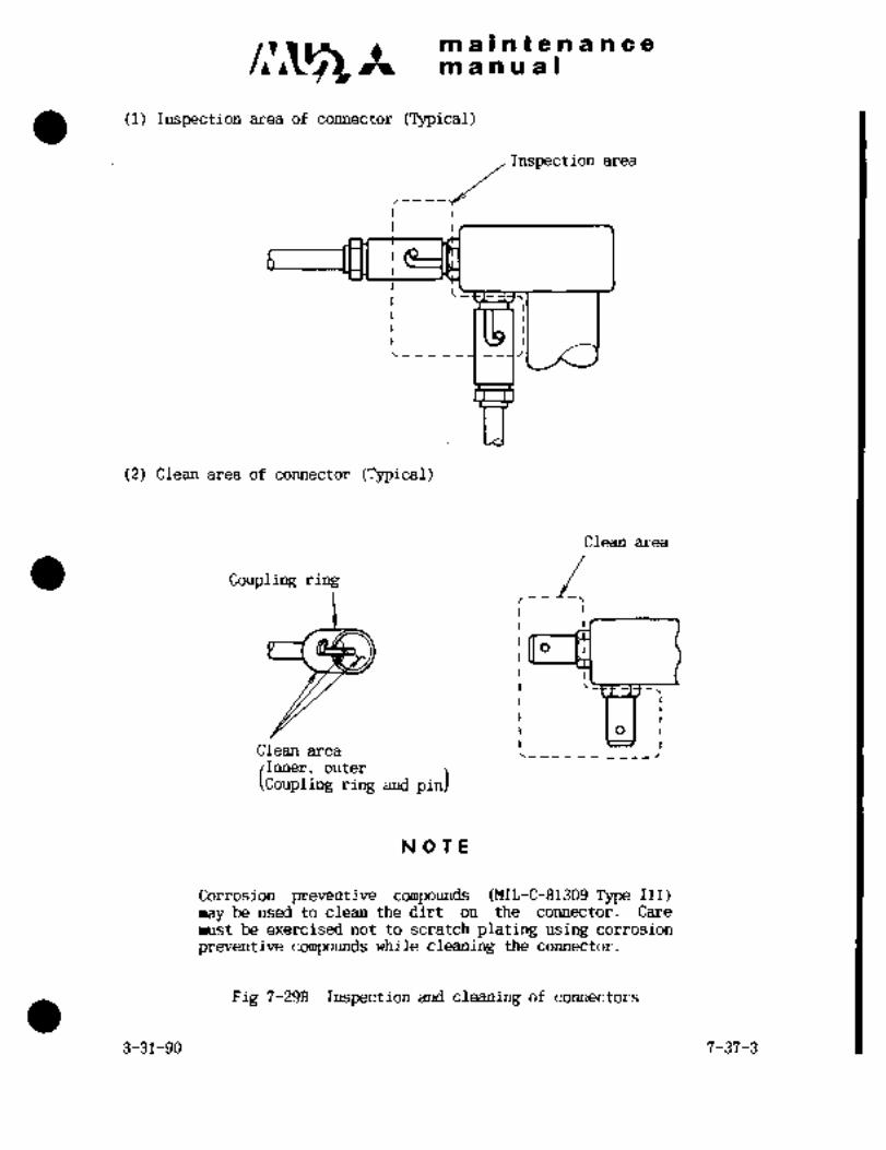
c~r Itmaintenancemanual
(1) Inspection area of connector (Typical)
Inspection area
(2) Clean area of connector (Typical)
Clean area
Clean area 1__________:outer
pin)
NOTE
Corrosion preventive compounds (MIL-C-81309 Type III)
may be used to clean the dirt on the connector. Care
must be exercised not to scratch plating using corrosion
preventive compounds while cleaning the connector.
Fig 7-29B Inspection and cleaning of connectors
3-31-90 7-37-3
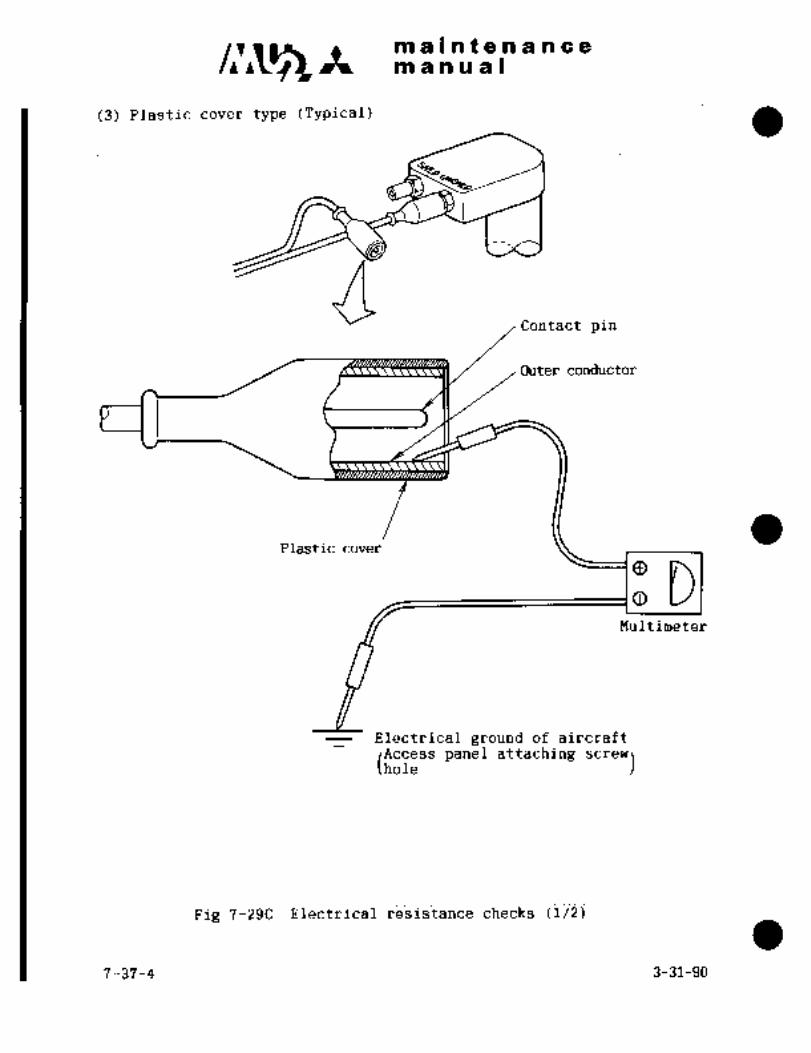
maintenanceman ual
(3) Plastic cover type (Typical)
QContact pin
Outer conductor
Plastic cover
OO DMultimeter
Electrical ground of aircraft
panel attaching screw)
Pig 7-29C Electrical resistance checks (1/2)
7-37-4 3-31-90
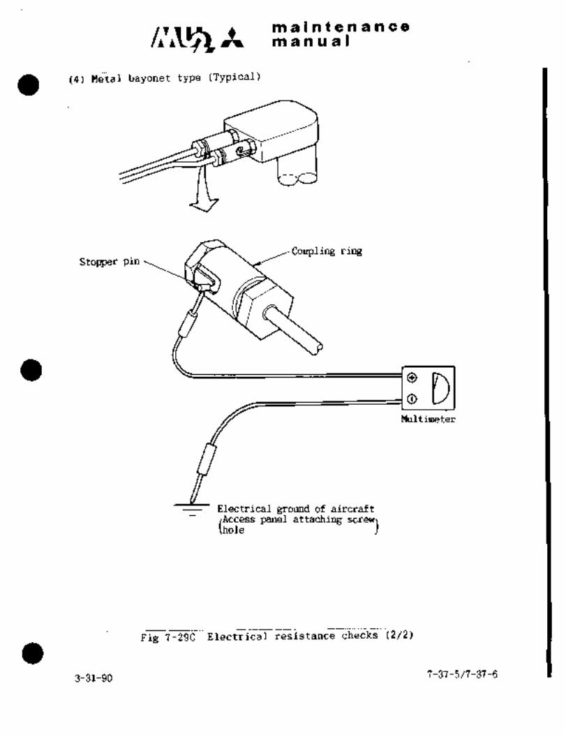
maintenancemanual
(4)Metal bayonet~type (Typical)
Coupling ringStopper pin
OO DMultimeter
Electrical ground of aircraft
(i~ss panel attaching screw)
Fig 7-29C Electrical resistance checks (2/2)
3-31-90 7-37-5/7-37-6
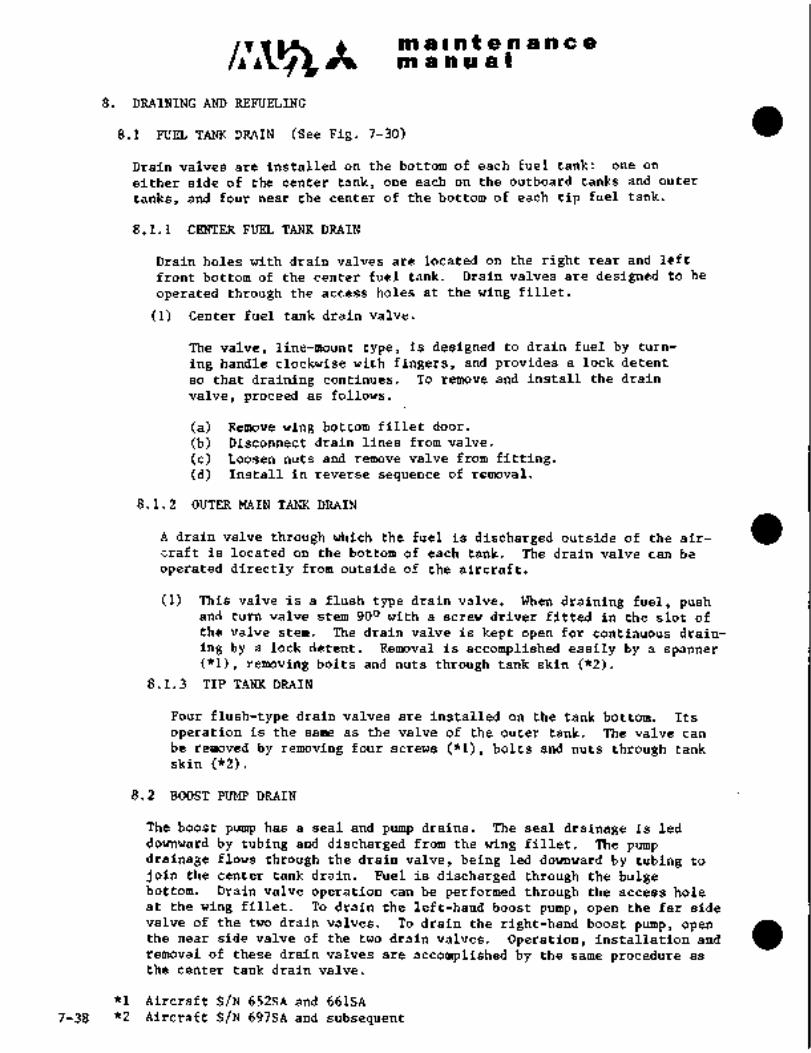
c,r~smaintenancem a a a a I
8. DRAINING AND REFUELING
8.1 FUEL TANK DRAIN (See Fig. 7-30)
Drain valves are installed on the bottom of each fuel tank: one on
either side of the center tank, one each on the outboard tanks and outer
tanks, and four near the center of the bottom of each tip fuel tank.
8.1.1 CENTER FUEL TANK DRAIN
Drain holes with drain valves are located on the right rear and left
front bottom of the center fuel tank. Drain valves are designed to be
operated through the access holes at the wing fillet.
(1) Center fuel tank drain valve.
The valve, line-mount type, is designed to drain fuel by turn-
ing handle clockwise with fingers, and provides a lock detent
so that draining continues. To remove and install the drain
valve, proceed as follows.
(a) Remove wing bottom fillet door.
(b) Disconnect drain lines from valve.
(c) Loosen nuts and remove valve from fitting.(d) Install in reverse sequence of removal.
8.1.2 OUTER MAIN TANK DRAIN
A drain valve through which the fuel is discharged outside of the air-
craft is located on the bottom of each tank. The drain valve can be
operated directly from outside of the aircraft.
(1) This valve is a flush type drain valve. When draining fuel, pushand turn valve stem 900 with a screw driver fitted in the slot of
the valve stem. The drain valve is kept open for continuous drain-
ing by a lock detent. Removal is accomplished easily by a spanner
(*1), removing bolts and nuts through tank skin (~R2).
8.1.3 TIP TANK DRAIN
Four flush-type drain valves are installed on the tank bottom. Its
operation is the same as the valve of the outer tank. The valve can
be removed by removing four screws (*1), bolts and nuts through tank
skin (*2).
8.2 BOOST PUMP DRAIN
The boost pump has a seal and pump drains. The seal drainage is led
downward by tubing and discharged from the wing fillet. The pump
drainage flows through the drain valve, being led downward by tubing to
join the center tank drain. Fuel is discharged through the bulgebottom. Drain valve operation can be performed through the access hole
at the wing fillet. To drain the left-hand boost pump, open the far sidevalve of the two drain valves. To drain the right-hand boost pump, openthe near side valve of the two drain valves. Operation, installation and
removal of these drain valves are accomplished by the same procedure as
the center tank drain valve.
*1 Aircraft S/N 652SA and 661SA
7-38 "2 Aircraft S/N 697SA and subsequent

ORIGINAL
As Received ByP~ a 1910 a a a a a a
a a a a PAT P
r iI: ´•~x C
:.t´•´•e :’’6:tli.
ii,
3"
~ji
iP’1´• 13
nrain valve-center tankDrain valve filter´• T..k,,,t porteL boost pump
11i
8 8 c8 Fb E o
B 8
Drain valve
outer tank 8~ J~rain valve tip tanknrain valve outboard tank
transfer pump
~bai: iF
FPfSI
.´•´•i
Flg. 7-30 Location of drain valve in fuel system
4-1-787-39

clr~s A m a II at a a a a a a
af a a a a I
8.3 TRANSFER PUMP DRAIN
The transfer pump has a seal drain and a pump drain. The seal is open
at the bottom or the pump. A hollow stem drain valve is provided in the
pump drain port. The valve is opened by inserting a screw driver in the
slot of the valve through a small hole in the lower access panel of the
tank and by turning it clockwise. The valve locks in OPEN position for
continuous draining. The transfer pump drain valves are also used as
the outboard tank drain valves. Removal and installation of the valve
can be accomplished by using a 3/8 in, square bar of a torque wrench,breaker bar or ratchet drive.
8.4 FUEL FILTER DRAIN
The hollow stem drain valve, the same as the transfer pump, is located in
the bottom of the filter, and is opened by inserting a screw driver in
the slot of the valve through a small hole in the access panel on the lower
side of the inboard leading edge, and by turning it clockwise. The valve
locks in OPEN position for continuous draining.Removal and installation of the valve can be accomplished by the same
procedure as the transfer pump. For access, remove the inboard leadingedge lower access panel.
7-40

V- 11’:1 ~,Bi 8 n (e
6i~ ii as a
s.~
:r~m alnlng In s"h8il be
iiith’the follb~
(1>
(2i sure fuel- a
(3) Ni~ak ure tha~t.a~l drain vali;~s ar~
O~en iippQjr iiace~.e door.
i5) Discijnnect hos~e at fuei iriiet cif engiiiej and i~onhect draining ´•hose lea~iri‘g to
a ~iessel.
(6) Close breaket ~AIN irALVE and PUMP.
(7) Piac~ MA~N TANKswitch to ON.
(8) Wing tank fuel is discharged ehroi~’g2i hose.
(9) When bd8st punip be~ins no-lohd i.udning and lio mor’ef~iel comes out,place MAIN TANK switch to O~F and:ope~ i~ircuit breaker.
(10) Drain remaining fuel througi~’ drairi:.iraive of e~ch t8hk.
(11) Open fuelfilter drain valve to drain.
´•(12) t~lose fuel filter~drain valv.::l´•i
~.6 RE~U’ELINd
R,fUelingis accomplish~: through ~e:fuel:f i;ler:ports located on the top of the
right ai~d left outer tanks;
rc"n’iiii~ijlCAUTION
(i) Caution should be exercised.during Irefuelingoperation. Aircraft, fuel truck´•and fuel nozile
must.be grounded.,
(ii) Beforerefueling, make sure that there is no
pressurein tip tahks by drawing air out through:’.sniffle’valve, and then remove::fueling cap.
8. 6.. 1 FU´•LL ´•REFU3ELING
(1) Reach L. H. filler pdrt using ladder work stand.
(2) R‘emove cap by lif~ing up::handl ~andlurningit co;unter-cloekwi-s~j.’
(3) GrounCfirefiielins, nozzle- to ~:aircraft,
(4) St~t fuel: flow.-:~’
(5) When fuel, level has reached filler port~; stop.´•filling;; and after few minutes
for staljiliiation, fill up the shortage.
(6) Install cap.
(7) Reach R.H. filler port and refuel-in accordance with pro~kdure: specified in
Para. (1) thru (6) abov8.’
7-41

X ni ~a i a t Qe i~ a HI id (P
;il a a a a I
8.6.2 PARTIAL REFUELING
(1)
(3) Service lower leveltants first with 60X of fuel td be add~d. Service
remainder 402 of fuel t~ opposite tank. If the lower leiiel tank
becomes full before filling 60% of fuel, fill up opposite tank.
8.6,3 TIP TANK REFUELING
CAUTION
Release tip tank pressure by pressingthe sniffle valve with a non-metallic
rod or probe. Do not stand directlyin front of the valve when releasing
pressure due to possible fuel ejectionthrough the valve.
(1) Reach filler port.(2) Remove cap by turning it counter-clockwise 90 degrees.(3) Ground refueling nozzle to aircraft.
(4) Refuel.
(5) When fuel levelhas reached filler port,stop filling; and after a
few minutes for stabflization, fill up the shortage.
(6)(7) Refuel the opposite tank in accordance with procedures specified in
Install filler cap.
Para.(l) through (6) above.
CAUTION
After refueling, close the fiiler port
immediately to keep out dust and water.
P1 OTE
In the following cases, drain water from each
drain valve.
(i) Before and after flight.(ii) 30 minutes after aircraft is moved from
warm place to cold place.(iii). 5 to 10 minutes after refueling,
8.6.4 OUTER TANK REFUELING
(1) Open the’ filler.port cover by pushing the latch with a finger tip.Remove the dip stick.
(2) Remode the filler port cap by pulling up the cap~:handle and turningit counter-clockwise,
(3) Ground refueling nozzle to aircraft.
(4) Refuel.
(5) When the fuel level has reached filler port, stop filling.(6) Install cap.
(7) Refuel the opposite tank in accordance with procedures specified in
Para.(l) through (6) above.7-42

c~r Itmaintenancemanual
8.7 BLENDING ANTI-ICING ADDITIVE TO FUEL
8.7.1 REFUELING FUEL CONTAINING ANTI-ICING ADDITIVE
Refuel in normal refueling procedures. This mixture can be used in
the main tank.
8.7.2 REFUELING WITH ANTI-ICING ADDITIVE
Blending procedures are as follows.
IWARNING)
"HI-FLO PRIST" may be harmful if inhaled or
swallowed. Use adequate ventilation. Avoid
contact with skin and eyes.
(1) Using "HI-FLO PRIST" blender manufactured by PPG INDUSTRIES, INC.,remove actuator cap.
(2) Press valve button (attached to tube and clip assembly) into valve
on top of can.
(3) Reattach actuator cap bypositioning onto can.
(4) Place clip with tubing onto fuel nozzle.
(5) To start flow, press actuator down fully. To stop flow, press tilt
to side and return to normal position.
(6) Use can upright and start flow of PRIST after refueling begins(refueling should be at a minimum rate of 30 gal/min. to a maximum
of 60 gal/min.). A rate of less than 30 gal/min. may be used when
topping off tanks.
(7) Stop flow of PRIST a moment before refueling stops.
IC~UTI(IN]CAUTION
Assure that the additive is directed into and
blends with flowing fuel from fueling nozzle.
Do not allow concentrated additive to contact
interior of fuel tanks or aircraft paintedsurfaces. Use not less than 20 fl. oz. of
additive per 260 gallons of fuel or more than
20 fl. oz, of additive per 104 gallons of fuel.
3-31-90 7-43

maintenancemanual
ALTERNATE BLENDERS
If alternate blenders must be used such as PRIST proportioner Model
PRE-101 or AP-2, use instructions furnished with blender.
8.7.3 MEASUREMENT OF ANTI-ICE ADDITIVE DENSITY
To measure density of anti-ice additive in fuel, use the followingequipment
Differential Refractometer AC-500
Seiscor Corp., Tulsa, Oklahoma
See Manufacture’s Manual.
7-44 3-31-90

CHAPTER
CABIN AIR
CONDITIOMING AND
PRESSURIZATION
SYSTENI

maintenancemanual
CHAPTER VIII
CABIN AIR CONDITIONING AND PRESSURIZATION SYSTEM
CONTENTS
1. GENERAL 8- 1
2. CABIN AIR CONDITIONING SYSTEM 8- 1
2.1 GENERAL DESCRIPTION 8- 1
2.2 REFRIGERATION UNIT 8- 3
2.3 WATER SEPARATOR 8- 7
2.4 ENGINE BLEED AIR SHUTOFF VALVE 8- 8
2.5 REFRIGERATION UNIT BYPASS VALVE 8-10
2.6 RAM AIR SHUTOFF VALVE 8-10
2.7 BLEED AIR PRESSURE REGULATOR 8-11
2.8 PRESSURE SWITCH 8-12
2.9 TEMPERATURE CONTROL SYSTEM 8-12
2.10 DISTRIBUTOR VALVE 8-15
2.11 COOLING AIR INTAKE SCREEN 8-16
3. CABIN PRESSURE CONTROL SYSTEM 8-17
3.1 GENERAL DESCRIPTION 8-17
3.2 CABIN AIR OUTFLOW VALVE CONTROL 8-20
3.3 OUTFLOW SAFETY VALVE 8-21
3.4 MANUAL PRESSURE CONTROL VALVE 8-22
3.5 PNEUMATIC RELAY 8-23
3.6 AIR FLOW VENTURI IAircraft S/N 652SA and 661SA) 8-24 13.7 JET PUMP VENTURI 8-25
3.8 E3ECTOR (Aircraft S/N 697SA and subsequent) 8-26 13.9 AIR FILTER 8-26
3.10 ENTRANCE DOOR INFLATABLE SEAL SYSTEM 8-27
3.11 INSTRUMENT AND WARNING LIGHT RELATED CABIN PRESSURIZATION 8-29
4. CONTROL AND TROUBLE SHOOTING FOR CABIN AIR CONDITIONING AND
PRESSURIZATION SYSTEM 8-30
4.1 AIR CONDITIONING AND PRESSURIZATION SYSTEM 8-30
3-31-90 8-i
c~r Itmaintenancemanual
4.2 OPERATION AND CHECK OF AIR CONDITIONING SYSTEM 8-32
4.3 TROUBLE SHOOTING CABIN AIR CONDITIONING SYSTEM 8-40
4.4 OPERATIONAL CHECK OF CABIN PRESSURE CONTROL SYSTEM 8-42
4.5 CABIN PRESSURE LEAKAGE TEST AND OPERATIONAL CHECK FOR OUTFLOW
SAFETY VALVE 8-43
4.6 TROUBLE SHOOTING CABIN PRESSURE CONTROL SYSTEM 8-45
5. AIR SUPPLY SYSTEM 8-47
5.1 GENERAL DESCRIPTION 8-47
5.2 PRESSURE CONTROL VALVE (18 PSI) 8-47
5.3 PRESSURE CONTROL VALVE (15 PSI) 8-47
I 8-ii 3-31-90

C~5 Itmaintenancemanual
i. GENERAL
The cabin air conditioning and pressurization system provides cabin tempera-ture control, ventilation and pressurization by air with controlled tempera-ture and pressure. For this’ purpose, left and right engine compressorbleed air from the final stage is used and sent to the cabin after temperatureis controlled by the air conditioning system. This system consists of the
refrigeration unit, water separator, temperature control system, and cabin
pressure control system, etc., and will maintain cabin pressurization, and
air conditioning on the ground or during flight. When the system is switched
to ram air condition during flight, cabin ventilation is accomplished with
ram air.
Cabin pressurization capability is 5.25 (*1), 6.10("2) psi maximum, that is, Iat an altitude of 25,000 ft., cabin pressure altitude of 8,500 (*1),6,700 (*2) feet can be maintained. Cabin pressure control and temperaturecontrol systems are provided with automatic and manual controls.
2. C~IN AIR CONDITIONING SYSTEM
2.1 GENERAL DESCRIPTION
This system controls temperature and pressure of engine compressor bleed
air and sends it to the cabin as air source for pressurization and air
conditioning. The system consists of refrigeration unit,´•water separator,
refrigeration unit bypass valve, cooling turbine bypass valve, ram air
system and air outlets.shutoff valve, engine bleed air pressure regulator, temperature control
High temperature and pressure air from the engine compressor is
regulated by pressure regulator and is precooled by precooler and primaryheat exchanger and then compressed into high temperature and high pressureair by the compressor. The air is again cooled by the secondary heat
exchanger and further cooled by the cooling turbine. (See Fig. 8-1)
The power absorbed by the cooling turbine is used to turn the compressorand fan connected directly to the turbine. The fan draws ram cooling air.
The cold turbine discharge air passes into the cabin for cooling throughthe water separator where.the condensed water is removed.
To provide cabin heating, high temperature air is branched off from the
upstream side of the precooler, regulated by refrigeration unit bypassvalve and mixed with cold water separator discharge air to provide air
temperature selected by cabin temperature control.
*1 Aircraft S/N 652SA
aAircraft S/N 661SA, 697SA and subsequent
3-31-90 8-1

maln5enancemanual
~I-
I
Engine
Cold air duct Conditioned airductbleedair,,
I Tooutboard
~lo O I I S1 I 11 1-TI 6bl O
8 Qol O
j:
I
Ram Air
To de-icer bootsEngineTo windshield anti-ice systembleed airTo tip tankTO door seal
__
O Refrigeration unit O Water separator inlet air temp. sensor
O Water separator O Windshield defog air outlets
O ´•Ref. unit by-pass va7e Mixing chamber
Cooling turbine by-pass valve O Forward conditioned air outlets
~O Ram air shutoff valve Main conditioned air outlets
O Bleed air shut-off valve O Cold air outlets ~For passengers)
O Bleed air checl valveCold air outlets (For pilots)
Air conditioning control unit Distributor valve
Cabin temperature controlCabin temperature selector Ceiling outlet
Auto-manual selector switchO Cooling turbineCabin air outlet selector switch
SWitChWarning light
Cabin temp. control selector and O Cabin temperature sensor
transfer switch
Engine bleed air
Vater’separator inlet air temp. controlII Engine bleed air
O Cabin supply air temp. sensor
Cooling air
QL´• Conditioned air
Cold air
Wiring
Fig. 8-1 Air conditioning system
8-2

m a’ln a a Iiln a7 at a ii a,n c a
Ih.oid~r to prevent wate~ separator i~let icing the water separator inlet
8ir tempei~ature is maintained at approirimately-38;0F (3PC) by mixing turbine
discharge air with from primary ~eat exchangerinlet through cooling turbine bypass valve. Cabin air temperature con-
trol is accomplished by controlling cabin supply air temperature, and the
air temperature is sensed to control the refrigeration unit bypass valve
automatically dr manually. Water separator inlet air temperature iscontrolled automatid8liy.
Cabin air outlets consist df the forwa´•rd, centeit and aft cabin air outlets
(LH and RH), private room conditioned air- outlets,.ceiling outlet and cold
airoutlets for pilotsand passengers.
2.2 REFRIGERATION UNIT
The refrigeration unit consists of precooler,heat exchanger (primary and´•secon’
dary), air cycle machine, water asi~irator, turbine bypass valve. and temperaturelimit’switch. The fin’an;i’ heat exchanger or the
plate´•´• fill type. The air cycle machine is the one in which compressor andfan are installed ona shaft supported with ball bearings. L;libricatingoil for the bearing is drawn up by wick and distributed throughout the
bearing cartridge by the use of. oil slingers. The water aspirator is an
ejector which uses some of the engine bleed air from the downstream side
of the secondary heat exchanger aspowersourceand sprays drained water
of water separator to cooled air side of heat exchanger’ in order to raise
cooling c~pacity of heat exchanger.
The turbine bypass valve is an electric motor type butterfly ´•valve which
controls Bypassed air flow.
The temperature limit switch actuates when the:compressor. dischargetempera’tur~ exceeds preset.point of´•’435 f 150F (224 80C) ~and’ the signalcloses LH engine bleed airshutoff valve and also illuminates the ASC
FAIL warning light.
2.2.1 REMOVAL. AND INSTALLATION (See Fig. 8-2)
2.2.1.1 Refrigeration Unit (Removal of entire’unit)
(1) ´•Removewfring conliectolrsfor turbine bypass’valve and tempera-
ture switch.
(2) Remove.screws at fan inlet, loosen clamp and remove’rubber hose.
(3) Loosen clamp at turbine, outlet ~and remove tubber hose.
(4) Loosen couplings at compressor inlet and primary heat ex-
changer outlet, and remove tube.
(5) Loosen coupling at primary heat exchanger inlet and, separatetube assembly upstream side.
(6)- Separate drain line for watei:separator. and water a$pirator.
(7) Rem6ve sensirig ~line forpressure.switch.8-3

’b";~
1. Refrigeration unit 1421
2. Water separator3. Refrigeration unit bypass valve
:4. Coolingturt´•Jine bypass valve
5. Ram air shutoff valve
1
13
I\12
ii I 3)- Pb
8 ~I3:
IC~
´•q pitoI~ 10. Venturi
(Ct~ 9/ ~1. pressure regulator a’
1 12. Pressure switch
j2
13. Temperature limit switch C1´•
14. Air cJ;rcle machineII 6. Temperature control system 15. Cooling air intake screen
7. Water separator inlet temp. sensor
8. Mixing chamber
9. Water drain pan
Fig,8-2 Air conditioning and pressurization equipment
O

C~t!’I‘n t ’ai. i~ ii= 8
(8) R~move aiit tubihg at ~recooler inlet.
(q) Remove bolts attaching unit to the frame.
(Id) ~einove i~ooling air disdhdrge port adapter.
(ii) Remove ~olts-connecting flanges or heat ei-
changer and separate precooler and ~eat exchanger.
(12) Cover all openings.
(i3) Remove the unit from the frame and take outboard from
fan housing through t~heiHaccess door.
(14) When other units interfere with the refrigeration unit,remove them if necessary.
(15) Install in reverse sequence of removal.
(a) Spray MS12´•2 Flourocarbon Parting Agent´• (Miller StephensChemical:Co., Canbury,Conn.)on the connecting flangesurface of precooler and heat exchanger and applyRTV60 and Thermolite 12 (General Electric Co.,Pittsfield, Mass.).
(b) Installation’torque of unit attaching bolts and con-
necting bolts of precooler and heat exchanger is 2’5 to
30 in-lbs.(29 t~o 34 kg/cm).
(c) Installation torque of couplings at primary heat´•ex-
changer inlet and optlet.and compressor inlet is 45 to
50 in-lbs.(51 to 57 kg/cm).
(d) .The nylon coupling nut of water separator drain line
should´•be re-tightened 2 or 2.5 turns more by tool
after hand-tightening,
2.2.1.2 Air Cycle Machine (Removalof single unit only)
(1) Remove attachingolts at the downstream tube of air cyclemachine and turbinebypass valveandSeparate tube assembly.
(2) Loosen´•couplings atcompressor inlet and outletand turbine
inlet and separate each tubeassembly’from air cycle maehine.
(3) Loosen ~hqse’ clamp at turbine outlet ´•and separate’ downstream
tube assembly from ai~ cycle machine.
´•(4) Cover all’’openings.
´•(5~ Removk bolts attacbingajr, cycle machine to heat exchanger´•.
(6) .Remove bolts at’taching: air cycle machine to fan housing.
(7) Remove ’air~ cycie,machine.
8-5

.m a 1 i~ P a i’L a a a ~Ci
c~ ~te
(8) Install in reverse sequence df removal.
(a)machine and fan housing,,heat exchanger and downstream
Installation torque df connecting bolts at air cycle
tube assembly of turbine bypass valve is 25 to 30 in-lbs.
(29 to 35 kg/cm)-.(b) Istallation torque of coilplings at compressor outlet
and turbine inlet is 45 to 50 in-lbs. (52 to 58 kg/cm).(c) Use as many washeic’s as to ~aintain gap tiei~ween
turbine housing flange and heat exchanger bracket within
0.016 in. (0.4 mm).
2.2.1.3 Turbine Byp~ss Valve (Removal of single unit only)
(1) Remove wiring conneator’from the valve and identify.
(2) Slide spring clamp and rubber hose back onto the downstream
ducts.
(3) Remove bolts attaching the valve to the heat exchanger.
(4) Remove connecting bolts at valve inlet and upstream duct
and remove the valve.
(5) Cover all openings.
(6) Install in reverse sequence of removal.
(a) Installation torque of connecting bolts at valve inlet
and up-stream duct is 25to 30 in-lbs. (29 to ?5 kg/cm).(b) Use as many washers as required to maintain gap between
valve attaching flange and heat exchanger bracket within
0.016 in. (0.4 mm).
NOTE
Do not incline air cycle machine with
lubricating oil more than 450 wherever
practicable. In case of reinstallingturbine bypass line, replace packing(694945129) at air cycle machine inlet
and gasket (691498150) at bypass valve
inlet with new ones.
2.2.2 CHECK AND REPLACEMENT OP LUBRICATING OIL
Check lubricating oil‘quantity every 100 hours and refill per’ below,as necessary.
(1) Remove filler plug (AN8i4-´•2DL) and packing (6949K9q2).
(2) Fill lubricating oil (MIL-L-23699) upto thelevel of filler port.
(3) Reinstall packing and filler’plug. Apply 15 to 20 in-lbs. (17 to
23 kg/cm) of torque.
8-6
1.;
C, Pal Itl f ieS.n a in c e
a
Ghahge;ubricatirig bil everl 00 hours as fbliows.
ilj R~ve scre~ (Nlcl60d3UB) and jssher (IIAS620ClbL) .r~aching sum~to air cycle ~achine;
(2) R~move and clean suinp ant~ refill with new oil (~IIL-L-23699) up to
the level of filler port,
(3) install li~mp. Replace packing (69ii94K3) with new one ~f necessary.
Tighten screw-with a 12 tb 18 in-lbs. (14 to 21 kg/cm) more
than ruiining.toi-que.
NOT E
Running to~que is a torque necessary to
turn -screw (torque before tightening),
CAU T ION
Do not allow solvent to enter any ro~atingcomponents. The air cycle -machine must not
be operated for 3 hours after filling with
lubricating oil. If the machine is to be
operated at~l hour after lubricating, the
wick shouldbesoaked with oil prior to
installing to ensure’immediate bearinglubrication.2.2.3 TEST
Carefully determine that the rotating section of the air cycle machine
is free fuming.
(1) Before installatidn
Carefully insert a non-metallic probe through the fan inlet and
gently turn the fan blades.
(i) After installation
Cain access to intake air duct, open spring door and carefullyinsert a non-metallic prdbe through the door and faninlet and
gently turn the fan blades.
2.3 WATER SEP~ATOR
The water separator.is locateb~ downstream of the turb’ine and-is designedto remove condensed wat~r from incoming air. It is divided into 4 parts
functionally: coalescer, swirl generator, discharger and bypass relief
valve. Small wafer drops in.the incoming air become larger drops in
thecoalescer and are’thrown:outward by.the centrifugal force‘in the
swirl generator and arecollected In the discharger. The water,´•then,
watera~pirator through drain line.isspraled at the upstream side (cold air)~ of heat exchanger by’means of
When thecoalescer is blocked and
difference pressure between ~upper and downstream reaches 3 ~t 0.5´• pei(0.21 f 0;:d4 kg/cm~):i i-be bypass relief´•valve is. opened and incoming air
’flows directly downstrean;;
8-7’.

zi tin t a a a ;em a n ri I
2.3.1 kEMOVIIL AND INSTALLATION
(1) Loosen clamps at inlet and outlet and remove rubber hose.
(2) S~earate drain line.
(3) Remove 2 screws attaching water separator to frame bracket.
(4) Remove wafer separator.
(5) Cover all openings.
(6) ’Install in reverse sequence of removal.
NOtE
Make sure that drain line (aspirator line) is
installed firmly to water separator. When con-
nections between water separator, nylon elbow
and line are faulty, water may spout out.
’2.3.2 CHECK, CLEANING OR REPLACEMENT OF COALESCER
(1) Loosen V-band coupling at the center of water separator and remove
end housing.
(2) Carefully remove coalescer from the inner housing and remove rubber
end from the flange.
(3) Check coalescer for damage. If not damaged, clean by washing in
amild soap solution, thoroughly rinsing and drying.
(4) Reinstall coalescer. Stretch rubber end with care.
(5) Make sure that all edges of coalescerare in the fixed position.
(6) Installend housing, tighten nut for~V-band coupling to 6 to
8 in-lbs. (7 to9kg/cm) torque.
2;4 ENGINE BLEED AIR SHUTOFF VALVE
The valve isinstalled´•in engine bleedair tubing in the nacellerear’
section ´•and controlled by the cabin air selector switch located on RH
switch panel. It is a butterfly valveoperated by 28VDC a~ctuator and
operating, time required from´•"full closel’ to "full’open" is 7.5 to 12
seconds.
8-8

c~s i~n a-r.n t Dn a a a a
a h a ~a I
2.4.1 REMOVAL AND INSTALLA’rION .(Fig. 8-3)
(1) Remove access eanel Ibcated in RH
upper icear~ sectidn of the
(2) Remove wiring connectors. ~k´• ~n
(3) Reli~ove joint clamps upstrearii and
downstreain of t~e valve.
(4) Remove valves and two gasket~.
(5) Cap valve ports.d
S~?"(6) InstallinTeverse sequence of
rembval.Fig. 8-3 Bleed$ir shutoff valve
NOTEORIGINAL
When bleed air shutoff valve is re- AS Received Byinstalled, gasket (Marman- 240.96-150-C)
sh$uld’be replaced with a new one.AT P
2.4.2 OPERATIONAL CHECK
(1) Remove access panel´• located,in RH.upper rear: sections of LH and RH
engines.
(2) Connect DCpower.source (battery or APU).
(3) Set circuit breaker:for.AIR COND of’the group AIR COND DE-ICE.
(4) Turn ~AIR COND. ~(cabin air selector switch located on RH switch
panel) toOEF. Make sureposition indicator:attached toeach
valvein LH and RHnacelles shows CLSE.
(5) Select LH,:check the actuation of the LH valve only, and´• make sure
OPEN is shown.
(6) Select BOTH, check the actudtion:of the RHvalve, and make sure
OPEN is ´•shown.
(7) Select RH, check the-ac~tuation of the.LH:vaLve, and make sure
CLOSE is shown.
(8) .Turn swi~ch toOFP.
8-9

m a I iii it a i;i a iii ic ~ec~a manual
2.5 REFRIGEKATIDN iTNIT B~PASS VALVE
This valvP is located on the bypass line connecting bleed line, upstreamof the precooler and mixing´•chamber, downstrPam of the water separator.This valve controls bleed bypass flow by means of signal´• from cabin tem-
perature regulator to maintain cabin temperature at the selected value.
This switch can also be directly operated by the pilot. Required time
from full close to full open is 7.5 to 12 seconds.
2.5.1 REMOVAL AND INSTALLATION (See Fig. 8-2)
(1) RH electric compartment doorat F.STA 8615.
(2) Remove wiring connector from the valve.
(3) Loosen coupling at valve outlet.
(4) Remove connecting bolts at valve inlet and upstream ductand
remove the valve.
(5) Cover all openings.
(6) Install´• in reverse sequence of removal.
Installation torque of´•´•connecting bolt is 25.to 30 in-lbs.’(29 to
35 kg/cm).
ORIGINAL
As Received By NOTEAT P
In reinstallation, replace gasket‘ (51134-10;1\).at valve inlet with new one.
2.6 RAM AIR SHUTO%F VALVE
This unit is located between ram’air intake and upstream of the mixingair selector switch to RAM to venti_chamber and is opened by setting cabin
late cabin with ram air.. If necessary, turn~manual pressure control valve
in the direction from INC to DEC positions. Ram air shutoff valve requires15 to 21 seconds ("1), approximately 1 second’ ("2) to full open from full close.
2.6.1 REMOVAL AND INSTALLATION (See Fig. 8-4)
(1) Remove LH access panel~of electrical
compartment; F.STA 8615.
(2) Remove wiring connector and bonding I:’’ h Y~wire.
(3) Remove valve attaching bolts.
(4) Remove valve and two gaskets.
’i’ ""’~"´•D´•´•´•- 1:11 1´•(6) Installin reversesequenceof
removal.Fig. 8-4 Ram air shutoff valve
8-10 *1 Aircraft S/N 652SA, 661SA, 697SA thru732SA
*2 Aircraft S/N 733SA and subsequent
m s’iiit 8 n gh i~ e
m ~a’n u a)
N6tlE
Replace with new.gasket (AN6230r9) wh~n´•
ram air shutoff valve is reinstalled. *1
CAU T´• iO N
Do not attempt t adjust limit switches; *1
2,6.2 OPERATIONAL CHECK
(1) Remove LH and elect~ic compartment door, F.STA 8615, as required.
(2) Connect DC current (battery or APU).
(3) Cldse .circuit dreaker AIR COND.
(4) Turn‘OFF cabin air selector, switc~ on RH switch panel and make
sure that thevalve position -indicatoy shows CiOSE.
(5) Turn to RAMand make’ sure this OPEN.
(6) Turn it: again to OFF and make ’sure CLOSE is Shown.
,.7 BLEED AIR PRESSURE REGULATOR
(7) Restore aircraft to original configuration.
This regulator is)located upstream of venturi in engine bleed air line and
regulates the -regulator output pressure at´• the ecified value. The regu-
lating pressure is: 33 f 2 psi C2.3 -10.14 kg/cm when the upstreampressure is 40 psi (2.8.kg/cm2) and 30 f 3 psi (2.1 f 0.21 kg/cm2) for 100
psi (7kg/cm2) of upstream pressur.e.
This regulator also works to control flow in combination with venturi.
2.7.1 REMOVAL AM) INSTALLATION
(1) Remove LH electric compartment door, F.STA ~8615;
(2) Removepressuresensing line.
(3) Remove 8 connecting bolts-at regulator inlet’’flange and remove´• valve.
(4) Cover all~openings.:
(5) Install inreverse sequence´• of´•~removal.
NO TE
In reinstallation, rep lace gaske ts 5 1 134-2008
ORBG\NAe ASat valve inlet and outli~t with hew, ones.
*L A.Lrcraft S/N 62sA, hhlSA.:6475A th;ou~h 7325A RECEI\IED BY
8-11
ni a h u a)iii a i i~ t a ii a ill ic 9
2,8 PR~SSURE SWITCH
This swifch is located on engine bl~ed air linei upstream of precoolerand actuates when the bleed air pressure exceeds 37 psi <2.6 kg/cm2) of
the specified value. The signal closes LH engine bleed air shutoff valve
and illuminates the "ACS FAIL" warning light.
2.8.1 REMOVAL AND INSTALLATION
´•(1) Remove wiring connector of pressure Switch.
(2) Disconnect pressure sensing line.
(3)- Remove 2 screws and remove pressure switch.
(4) Cover all openings.
(5) Install in reverse sequence of removal.
2.9 ~TEMPERATURE CONTROL SYSTEM~
The temperature controlsystem in air conditioning system consists of
the following two systems.
1. Cabin’temperature control system.
2. Water separator inlet temperature control~system.
2.9,1 CABIN TEMPERATURE CONTROL
The cabin temperature control system maintains cabin temperature at
the preset temperature. The major components are as follows:
(1) Cabin temperature control.
(2) Cabin temperature selector (cockpit, cabin).
(3) Auto-manual selector switch.
(4) ´•Cabin temperature sensor.
(5) Cabin temperature sensor fan.
(6) Air supply temperature sensor.
(7) Air supply temperature limit switch.
(8) Transfer switch.
The cabin temperature contfol is made by regulating opening’of refrigera-tion unit bypass valve and adjusting mixing ratio of engine compressor
bleed air and cold water separator discharge air. In automatic control,the signal controlling valve opening is originated by thedifference
between cabin temperature settled by the selector.
The signal-passes temperature control circuit before.reaching valve
and standard value of supply air temperatureis settled. This standard
value is comparedwith the temperature sensed by duct sensorand the
difference actuates bypass valve.
8-12

~8’ a ii~ ii1. bi~B~oa a B a a
i~´• ~bO .to Q00´•~ (´•lj.~O.rarige, ~ji se
supp13 ii~ coritt~lled’ within th~ ´•ii~d3it o~:18~" lao;F ~2. to´• 850 f 5.506). Iii inanu~l cohtic~li 360F ~2i20C)
8r cdld’ ai~ is 8btain~a ~h iljjOLD" p~Eiiti6ri’df selectorsi;iitiSh ~irid.2000 f 10OP ~.5dC) oi hbt aii- which is t~tie actuatingpdi,t cjf ~.bin siiI;pi~ ti~perature limit switch is obtained’ in"ZIOT"
2´•;9.2 WA~ER S~PARATdR Cd~jTROi; SYST~
The water separatoir ihlet femperatuirii~ cbritrol’: slsstei: maintains the
water separator inlet Bir temperat~ireare as follows:
i. Watei: inlet air temperature control.
2. Water separator inlet s~nsor.
The temperature control is made by adjusting opening oT turbine bypassvalve.
2,9.3 REMOVAL INSTALLATION
C
Rig. 8-5 ´•WateZ separator inlet temp. sensor
8-13

maintenancenT anual
2.9.3.1 Cabin Temperature Control (See Fig. 8-2)
Remove LH electronic compartment access door at F.STA 8615.
(2) Remove wiring connector from the control.
(3) Remove 4 screws attaching the control.
(4) Rembve thecontrol.
(5) Install in reverse sequence oP removal.
2.9.3.2 Water Separator~ Temperature Control (See.Pig. 8-5)
(1) Remove LH access panel of electrical compartment F.STA 8615.
(2) Remove wiring connector.
(3) Remove screws attaching the control.
(4) Remove thecontrol.
(5) Install in reverse sequence of removal.
2.9.3.3 Water Separator Inlet Temperature Sensor
(1) Remove LH electric compartment door at F.~STA 861.
(2) Remove wiring connector from the sensor.
(3) Remove sensor and gasket.´•(4~ Install in reverse sequence of removal.
NOTE
If gasket (MS28778-8) is damaged, replace.
2.9.3.4 Cabin Supply Air Temperature Sensor
(1) Remove RH junction box cover.
(2) ’Remove wiring connector.
(3) Remove sensor and gasket.(4) Install in reverse sequence of removal.
NOTE
If gasket (MS28778-8) is damage~-, replace.
2.9.3.5 Cabin Supply Air Temperature Limit Switch
(1) Remove RE junction box cbver.
(2) Remove wiring connector.
(3) Remove screws attaching the control.
(4) Remove the_ cbntrol.
(5) Install in reverse sequence of removal.
NOTE
If gasket ~828778-5, S/N 652S~ and66lSA;MS2778-8, S/N 697SAand up) is damaged,
replace it.
8-14

m I drC e
ota a a ib tjl i)
r.9,3,8 ~enipBratuPe anh Fan
I’l) R.nidire ~aiiel d~ the LH sii~de ht F.’S~A 58’90.
(2) Remoii~ screws attaching bracket t6 side panel,~3) Remd~e wiring coahector.
(4) Be~mdte seii6or. and fan.
~5j rnstgll in reverse ~equehde
2. 10 DISTRIBUTOR VALVE
The distributor vaiveisinbtai~ed i~nthe conditiorded air ti~bingbettjeenaft pressurizing bulkhead and side ~anel, and distri6utes~air ~mong condi-
tioned, air outlets anh ceiling outlet. This valve is actuated by turningthe switch "CABIN AIR OUTLE~" to "CEIL", and thereby airflow from cabin
conditioned air outlets decre~ses and comes out of the ceiling outlet.
This valve produces satisfacto~y cooling results if operated in coolingcondition.
2,10, 1 REM’OVAL AND INSTALLATIO~ ´•(See Fig, 8-6)´•
(1) Remove main junction bbx: and RH side anel.
(2) Remove-wiring from rotgrysoienoid.(3) Remove bracket on which´• rotary solenoid is ii~stalled, from: valve;
bocly.-(4) Disconnect´•rubber duct downstream of th~´•valve.(5) Remove clamp,(6) Remove screws attaching the valve to bulkhead and remove the valve.
(7) -,Install in reverse sequence ofremoval.
i. Rotary solenoid´•
2´•. Bracket ~1
3. .Rubber duct
4. Clamp
s.:so,e;l:-,:i.
5
Fig. 8r6 Dls tributer valve
8-15

c~x ni a i´•h t e II1 n c e
2.10.2 OPERATIONAL CHECK
(1) Connect DC power (battery or ground power source).
(2) Close circuit bre~ker AIR COND.
(3) Turn the switch CABIN AIR OUTLET on RH sw’iteh panel to CEIL and
ensure valve operation.
2.11 COOLI´•NG AIIR INTAKE SCREEN CSee Flg. 8r´•7)
A screen is installed’in the cooling air fntaketokeep’sand and foreignobjects from entering the air cycle machine. Two relief doors are pro-vided to draw air from air conditiong electrical compartment should the
screen become blocked.
2.11.1 REMOVAL AND INSTALLATION
(1) Remove -LH door of electric compartment, F.STA 8615.
(2) Remove rubber seal at joint of cooling air intake andfan housingof refrigeration unit.
(3) Remove screws and cooling air intake from aircraft.
(4) Remove screws and screen from cooling air intake.
(5) Install in reverse sequence of removal.
Screw
aRubber
’iseal
C‘Screen Screw
Fig. 8-7 Cooling air intakeScreen
8-16

C~3W a e~8
ili~ a i~ iisl d
3.
3;1 DESCRIPTION
tiibls c~bin at apressure ’~ontfijl con
Speclfi’e’d i Cabii~ cii~i‘t’irol is by thi~dttlingair flow Into c$~in thlo~gh Bir sy~tem.
The major 8bmponents bf ~is systeih are as follows (See Fig. 8-8)~
(I) Cabin~air dutflow valve control,
(2) Outfldw~ safety valve.
(3) Manual ’Pressure control
(4) pneumatic rela>is.
(5) air f16w ventuiri (AircraftS~N 652SA and 661S~).
(6) Jet pump venturi (Aircraft S/N 652SA and 661SA).Ejector 697SA and si~bsequent).
(7) Filter.
(8) Ground test valve.
Cabin´• pres~ure control’ automatically ormanually the
following operations,
(1) Cabin altitude- control.
(2) dabin rate of climb control.
(3) Maximum (positive) differential pressure relief control.
(4) Negative pressure relief control.
(5) Cabin pressure dumping control.
Discharged air from the cabinenters the electronic compartment in the
airplane-nose .through outflow safety valve(s) installed on the forward
pressurized ´•bulkhead and performs heating and/or cooling for~´•the elec-
tronic compartment and ’thengoes o;utboard.
8-17

0,
OD
s I 1TICE3 Fn\1 8
9 2op 4 7
7 b
03
h C~ C~
Z
c~ 2 4
~s I a
C 1
rn m 3 1 _1
Zrlm
~D 9 33,ovll
F: Components of cabin pressure control I II I#I II Isystem at F. STA. 1080-1820 ill r~ll niJ1 T 4 3
=3v, L:o\~C
Cabin air outflow valve controlo\ m i.
2. Outflow/safety valve I s 3)(3~E3
3v 3. Manual pressure control valve
3)4. Pneumatic relay3N 5. Air ~now venturi
5
3
i6. Jet pump venturi C)
7. Filter (38. Ground test valve Ih II H db II 11 ,9
9. Tubing for atmospheric pressure IB~" 6
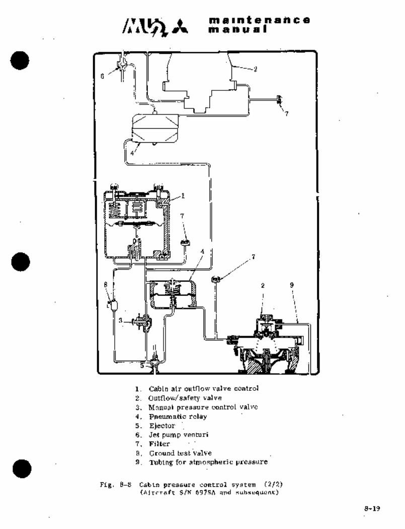
k´•i ni -Iht bi i~ ai n C ~ailli;li i~ii ii ill U~a I
si
~9 1l 4
´•8 11~ 7~ 2’ 9
i. Cabin air outflow´•valve control
2. Outflow/ safety valve
3. Manual pressure control: valve
4.’ Pneumatic .relay
5, Ejector6; Jet pump ~irentui´•i
7; Filter
8. Ground´• test val´•ve
9. Tubing for.atmospheric .pressure
Fig. 8-8 Cabin pressure dontrdlsystem (2/2)(Aircraft´•S/N 697SA and subsequent)
8-19
c;r~s It m a at g’n a to a a
manual
3.2 CABIN AIR OUTFLOW VAZ~VE CONTROL
This control unit is installed on the RH switch panel of the pilot seat
and controls cabin altitude and cabin rate of climb. To this unit are
connected tubes sensing cabin pressure and atmospheric pressure and a
tube co~nected to the outflow safety valve through a relay. On the
control unit there is provided a cabin altitude selector knob and a cabin
rate of climb control knob.
The former is used to select desired cabin altitude during cruising byturning the knob and setting the pointer to desired cabin altitude.
Selectable range of altitude is from -1,000 ft. to 10,000~ft. If the
pointer is set to ~esired altitude, the maximum aircraft altitude at
which aircraft can fly with the desired cabin altitude is indicated in
a small window below the dial.
At altitudes above this, cabin pressure is constantly maintained at a
value of 5.25 (*1), 6,0 0.1 (*2) psi higher than atmospheric pressure.A cabin rate of climb control knob is provided to controlcabin pressure
variation during climb and descent and is capable of controlling cabin
rate of climb between 50 ft/min. and 2,000 ft/min. Marking in the center
between "MIN" and "MAX" corresponds to rate of climb of 500 ft/min.
3.2.1 REMOVAL AND INSTALLATION (See Fig. 8-9)
(1) Remove three tubesconnected to thecontrol unit.
(2) Remove four screws attaching the control.
(3) Removeelectric wiring for instrument light.
(4) kemove the control and cap ports.
(5) Install in reverse sequence of removal.
CAU ’1 IOP1
Do not attempt to adjust or repair the
control unit. Replace ft if trouble occurs.
*1 Aircraft S/N h5?SA
*2 Aircraft S/N 661S~, 697SA and subsequent
8-20

ORIGINAL
As Received By al IPi ~t g In is as
AT P a a 1
´•rC~
Fig. 8-9 Cabin air outflow valve Figi 8-10 Outflow safety valve ("1)
3.3 OUTFLOW SAFETY VALVE
This valve controls discharged airflow from the cabin by a signal lairpressure):from the cabin air outflo~i valve control in order to control
cabin air pressure and, at the-same time, performs maximum (posit-ive)differential pressure.yelief and.negative pressure relieft Controlled
pressure fromthe cabin air outflow valve control through a relay is
applied to one side of the diaphragm in the valve and cabin pressure on
the other side. The differential pressure across the diaphragm moves a
poppet valve attached to a diaphragm controlling the area of the outletI’
6.0 f 0.1 (*2) psi during climbsection for cabin pressure or (xl),or in case of failure of automatic control of cabin air outflow valve
control. The maximum pressure relief mechanism, which is actuated bydifferential pressure between cabinpressure and atmospheric pressure,
performs pressure relief, and,.t~herefore, differential pressure does not
exceed the specified ´•value. In case of rapid descent, if cabin pressurebecomes less than atmospheric pressure, differential pressure between
cabin and atmosphere moves the poppet valve to prevent negative differen-
tial pressure from increasing.
3.3.1 REMOVALANDINSTALLATION (See Fig. 8-10)
(1) Remove four tubes (srl) ortwo rubber hoses (*2) connected to valve.
(2) Remove eight screws ("1)~ or.16 nuts and washers ("2) attaching valve.
(3) Remb~e valve and seal.
Rer?ove two unions and one: tee (*1) for tub´•e’connection and cap port.
(5) Install in reverse Sequence of removal.
*2 Aircraft S/N 697Sh and subsequ~ntBW861NAL As
kl Ati.CruTL S/N clftl~h61Sh
RECEIVED BY ~iB$ 8-21

c~5 *t a e at ~.n d a c a
lab a a or a
~RMING
After removal, check for tobacco tar and other
foreign matter accumulated on poppet valve and
popp~t seat and clean with dry cleaning solveilt
(~-S-661). When solvent is being used, adequateventilation should be provided and open flame
should not be permitted near the work site.
C~UTION
Do not attempt to adjust or repair the outflow
safety valve. Replace. it, if trouble occurs.
3.3.2 CHECK
(1) Wipe valve attaching seat and its vicinity on airframe side with
clean sqft cloth moistened with naptha (MIL-N-15178) to remove
oil and dirt.
(2) ´•When seal is.damaged or has deteriorated, replace it.
(3) Apply ~ealant (MIL-S-8802 Class B) to circumference of valve
attaching flange and screw heads which may cause a leakage.
CAUTION
Be careful not to apply sealant
to poppet´•valve and/or poppet seat.
(4) When the aircraft has not been flown for one consecutive month or
longer, apply a negative pressure of 5.0 to 5.3 psi ("3), 5.9 to
6.1 psi (*4) to the atmospheric port of the valve before flight,and ensure poppet valve is actuated.
3.4 MANUAL PRESSURE CONTROL VALVE
One end of this valve is located between the cabin air outflow valve
control and pneumatic relay and the other end is connected to a jet
pump venturi ("1), an ejector ("2). In case of failure of the cabin air
outflow valve control, cabin pressure is controlled manually by this
valve and ram air ventilation can be made by this needle type valve
according t~o RAM position qf cabin air selector and fine adjustment is
possible.
kl Aircraft S/N 652SA and 661SA
j~2 Aircraft S/N 697SA and subsequent.1"13 Aircraft S/N 652SA
k4 AircraftS/N 661SA, 697SA and subsequent
8-22
nl a n ~e iPP (i~ ~biia a a aii a I
3.4.1 A~jl) INSTAiiATIijN
(1) Remijve tub~s (2 eaij td iiaive;
(2) Remdve scirews(4 iia.) attached to switCh panel..
(:3) Remove iialve aiid cap P;orts.
i;b) In~tali in r~eberse sequence df removal.
Shobld the manual pressure c~ontrol valve
develop trouble,’ replace it. Do not, dis-
asse’mble the iralve or repiac~e component
parts except to clean the valve parts and
pa~sageswith compressed air.
3.5 PNEUMATIC RELAY (Fig. 8-12)
This relay is divided’ into two parts by a diaphragm. Control pressurefrom cabin air outflow valve contrbl is applied to one, side and air
pressure chamber of’outflows’afety valveis applied to the other Side.
Adcordirig to diaphragm motion, a metering valve is provided iri outflow
safety valve to control airflow to ejector. Small fluctuation of control
pressure from cabin air outflow valve control is -transmitted to metering
valve, which,in turn, controls passage between reference pressure chamber
to vacuum´•source of jet pump venturi ("1), ejector (jt2), andoperatesoutflow safety valve rapidly and positively.
3.5.1 REMOVAL AND INSTALLATION
(1) Remove tubes (3 ea.)- attached to relays.
(2)’ Remove bolts (2 ea.), nuts (2.ea.), washers (2ea.) and-cushion
(2 ea.) attaching relay.
(3) .Remove relay.
(4): Remove imions -and elbow or tee from relay’and cap ports.
(5) Install in reverse sequence of r.emoval.
NO T´•E
(i) In.cas~’:of-trouble of pneumaticrelay:,’replaceit with hew one
without perrdrmingrepair dr
adjustment.
(ii) If attaching cushion -is ´•found.
deteri6rated, replace cushion´•i:~
*1 Aircraft ´•S/N 652SA and 661SA
*2 Aircraft S/N 697SA and subsequent8-2’3
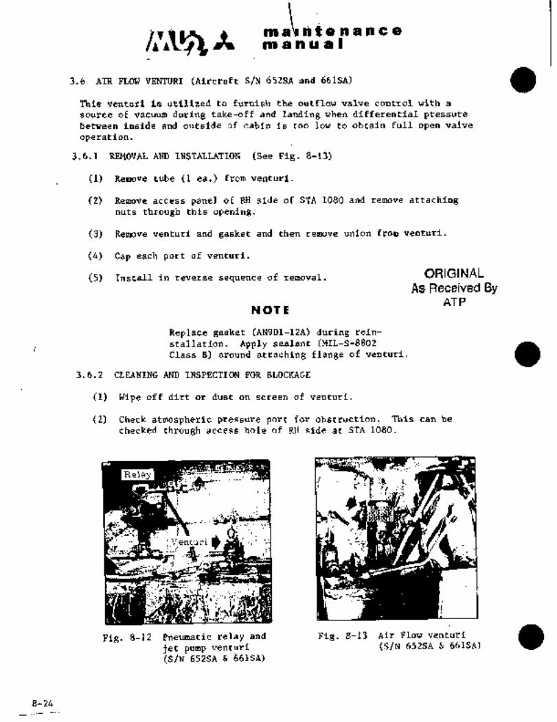
h t e.ri ii a a
m a a ii a I
3.6 AIR FLOW VENTURI (Aircraft S/N 652SA and 661SA)
This ventuti is. utilized to furnish the outflow valve control with a
source of vaci~um during take-off and landing when differential pressure
between inside and outside of cabin is too low to obtain full open valve
operation.
3.6.1 REMOVAL AND INSTALLATION (See Pig. 8-13)
(1) Remove tube (1 ea.) from venturi.
(2) Remove access panel of RH side of STA 1080 and remove attachingnuts through this opening.
(3) Remove venturi and gasket and then remove union from venturi.
(4) Cap each port of venturi.
(5) Install in reverse sequence of removal; ORIGINAL
As Received ByAT P
NOTE
Replace gasket (AN901-12A) during rein-
staIlation. Apply sealant (MIL-S-8802Class B) around attaching flange of venturi.
3.6.2 CLEANING AND INSPECTION FOR BLOCKAGE
(1) Wipe off dirt or dust on screen of venturi.
(2) Check atmospheric pressure port for obstruction. This can be
checked through access hole of RH side at STA 1080.
.s
Relaya
I I´• I
1
ir,´•ir
t t
i
l~j Ir~
Fig. 8-12 Pneumatic relay and Fig. 8-13 Air Flow venturi
jet pump venturi (S/N 652SA 661SA)
(S/N 652SA ti61SA)
8-24

iri i~ i ip f ;e:’i~ia a ;6: a
m a a ;ia ~i I
3.7 JET PUMP tjEN;rZTRI
(1) Fdrward jet ~unip 652Sa’and 661SA)
This vei~turi produces vaciium pres~ure with high pressure air and
controls teference pressure of outflow Shfety valve through a
pneurhatic r‘el~y. It is also connect’ed to a manual pressure contr81
val~ie to control the valve.
Pressure regulated engine bleed air is used ´•for high pressure air
source.
(2) Aft Jet Pump Venturi
This venturi produces vacui~m pressure with high pressure air and con-
trols reference pressure of outflow safety valve thrdugh a pneumaticrelay. If is also connected to a manual pressure control valve to
control the valve.
Pressure regulated engine bleed air is used forhigh pressure air
source.
j.7.1. REMOVAL AND INSTALLATION(See Pig. 8-12)
(1) Remove connecting tubes (3 ea.).
(2)~ Remove screws (2 ea.) and nuts (2 ea.) attaching venturi.
(3) Remove venturi and’seal. Remove union (3 ea.)and cap each port.
(4) Install in reverse sequence of removal.
NOT IE
If seal (010A-63113)is damaged or deteriorated,
replace it. Apply Sealant (MIL-S-88O2Class B)around venturi attaching flange.
8-25
m a ~nt an a n a a
m a a r~ is ii
:3.8 EJECTbR (Aircraft S/N 697Stl and subsequent)
This ej~cfor produces vacuum pressurewith high pressure ai~ and controlsreference chamber of outfldw´•safety valve through reference pressure ofcabiri pressure regulator and pneumatic relay. It is ~lso used as vacuum
source in manual pressure regulating. Pressure regulated engine compressorbleed air-is used for high pressure air source.
3.8.1 REMOVAL AND INSTALLATION
(1) Disconnect tubings and remove fitting.
(2) Remove attaching bolts of ejector plate and remove ejector from
airframe.
(3) Remove plate and seal by removing screws.
(4) Cap each port.
(5) Install in reverse sequence of removal.
NOTE
When seals (035A-63113 and 035A-63115)become damaged or deteriorated, replace them.
Apply sealant (MIL-S-8802 Class B) around
ejector attaching plate to prevent leakage.
3.8.2 ´•IMSPECTION FOR BLOCKAGE
Check ejector discharge port in nose landing gear well for blockage.
3.9 AIR FILTER
The filter prevents dirt or tobacco tar from entering cabin pressure sensingtubes of cabin air outflow valve controls and outflow safety valve.
This filter consists of a nylon screen for large matter and a filter
element for small particles.
3.9.1 REMOVAL AND INSTALLATION (See Fig. 8-14)
(1) Remove connecting tube (1 ea.).
(2) Remove cushionclamp attaching filter.
(3) Remove filter. Cover inlet~and outlet air ports.
(4) Install in reverse sequence of.removal.
8-26’
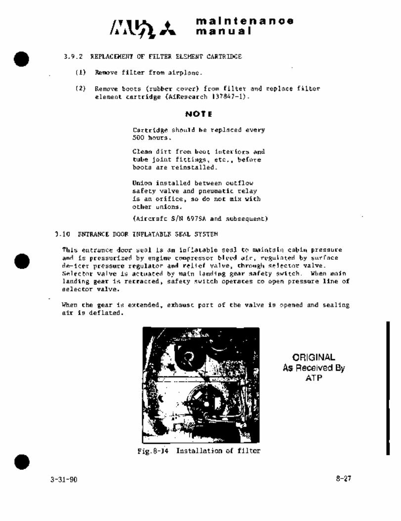
maintenancemanual
3.9.2 REPLACEMENT OF FILTER ELEMENT CARTRIDGE
(1) Remove filter from airplane.
(2) Remove boots (rubber cover) from filter and replace filter
element cartridge (AiResearch 137847-1).
NOTE
Cartridge should- be replaced every
500 hours.
Clean dirt from boot interiors and
tube joint fittings, etc., before
boots are reinstalled.
Union installed between outflow
safety valve and pneumatic relayis an orifice, so do not mix with
other unions.
(Aircraft S/N 697SA and subsequent)
3.10 ENTRANCE DOOR INFLATABLE SEAL SYSTEM
This entrance door seal is an inflatable seal to maintain cabin pressure
de-icer pressure regulator and relief valve, through selector valve.andis pressurized by engine compressor bleed air, regulated by surface
Selector valve is actuated by main landing gear safety switch. When main
landing gear is retracted, safety switch operates to open pressure line of
selector valve.
When the gear is extended, exhaust port of the valve is opened and sealingair is deflated.
ORIGINAL
As Received ByAT P
i;,
Fig.8-14 Installation of filter
3-31-90 8-27
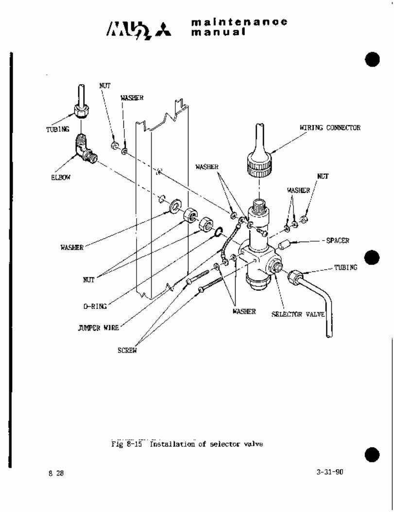
maintenancemanual
NUT
WASHER
TUBING WIRING CONNECTOR
WASHER
ELBOW
WASHER
N[JT
4iWASHERSPACER
O-RING
rTUBING
NUT
WASHERSELECTOR VALVE
JUMPER WIRE
SCREW
Fig 8-15 Installation of selector valve
8-28 3-31-90

maintenancemanual
3.10.1 REMOVAL AND INSTALLATION OF SELECTOR VALVE (See Fig.8-15)
(1) Remove LH electric compartment door at F.STA 8615.
(2) Disconnect wiring connector from the valve.
(3) Disconnect jumper wire.
(4) Disconnect tubing.(5) Remove the valve attaching screw.
(6) Remove valve and cap each port.(7) Install in reverse sequence of removal.
3.10.2 PROCEDURE FOR GROUND INSPECTION OF ENTRANCE DOOR PRESSURE SEAL SYSTEM
(1) When ground air source is used:
(a) Connect DC power (ground power or battery).(b) Connect high pressure air source to ground test port of
de-icing system and close entrance door.
(c) Supply pressurized air gradually and stabilize pressure at
30 psi (2.1 kg/cm2).(d) Close circuit breaker DOOR SEAL, open LG POS IND circuit breaker
and make sure that seal ispressurized and inflated. Check for
air leaks at seal.
(e) After confirming (d), open circuit breaker and make sure
seal pressure is deflated.
(f) After confirming (e), restore airplane to~original condition.
(2) (a) Make preparation in accordance with (l)(a) above and close
(b) Run up engine, per AIRPLANE FLIGHT MANUAL.
entrance door.
(c) Open circuit breaker LG POS IND and close DOOR SEAL circuit breaker.
(d) Make sure seal is pressurized and inflated and check for air
leaks at seal.
(e) Open circuit breaker DOOR SEAL, close LG POS IND circuit breaker
and make sure that the seal pressure is deflated.
(f) Shut down engine and restore airplane to original condition.
CAUTION
Do not operate engine unless entrance
door is fully closed. Entrance door
must not be opened during test.
3.10.3 PRESSURE LINE DRAIN
(1) When ground air source is used:
(a) With the entrance door open, perform steps (a), (b) and (c)of paragraph 3.10.2 (1).
(b) Close circuit breaker DOOR SEAL and drain water from entrance
door pressure line connector with compressed air.
(c) After completing step (b), open the circuit breaker and wipeoff water drops around the connector.
(d) Restore airplane to original condition.
3-31-90 8-281/8-28-2 1
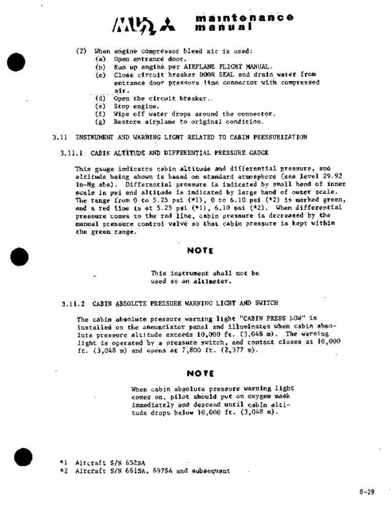
ii tti 2 ~i ih a ri C a,
i~ii ai a id ii~ III
(2) tjh~n erigiiie l;lee8 air is usea:
(a) Opeli entiraiiti~ dbor t
’ib) Run Gp ehgi~i8 per AIRPLANE FiiGEii’
(c) Cldse circuit breaker DOOR SEAjL ah;l drain water from
entrance door pressure lirie connector with compressedair.
i;d)0pen the circuit breaker..(e) Stop engi~e.(f) ~ipe off water‘iiFops ari;iind theconnector.(g) Restdre airplank to original condition.
3.11 WARMING LIGHT RELATED TO ~ABIN PRESSUiZIZATION
3.11.1 CABIN ALTITUDE.AND ~IFFERENTIAL PRESSURE GAUGE
This gauge indicates cabin altitude and differential ’pressure, and
altitud(l being shown is based on stalidard atmosphere (sea level 29.92
in-Hg abs). Differential pressur~ is indicated by small hand of inner
scale iii psi and altitude is indicated by large hand of outer scale.
The range from O to ~.25 psi (nl), O to 6.10 psi (´•k2) is marked green,
and a red line is at 5.25 psi (*1), 6~10: psi ("2). When differential
pressure comesto the redline, cabinpressure isdecreased by the
manual pressure control valve so that cabin pr~ssure is kept within
the.green ?ange
NOTE
This instrument shall not be
used as an altimeter.
3.11.2. CABINABSOLUTE PRESSUREWARNING LIGHT AND SWITCH
The cabin absolute pressure warnirig light "CABIN PRESS~ LOW" is
installed on the annunciator panel and illuminates when cabin abso-
lute pressure altitude exceeds 10,000 ft. (3,048m). The warning
light is operatedby a pr~ssure switch,and contact closes at l0,000ft.’ (3,048 m) and opens at 7,800 ft. (?,377 m).
NOTE
When cabin absolute pressure warning lightcomes on, pilot´•´•s~oiild put on oxygen mask
immediately and:;lescena.until cabin alti-
tude drops below’16,000 ft.(3,048 m).
´•:´•I P;ircraf.t S/N 652SA
*2’Aircraft- S/N 661SA,697SA and subsequent
8-29

at a I-h t a a a ii a e
m a a a a I
4. CONTROL AM) TROUBLE SHOOTING FOR CABIN AIR CONDITIONING AND PRESSURIZATIO~1SYSTEM
4.1 AIR CONDITIONING AND PRESSURIZATION SYSTEM
Switch panel for air conditioning and pressurization control is shown
in Pig. 8-16.
4.1.1 CABIN AIR SELECTOR SWITCH
This switch selects supely air for air conditioning and pressuriza-tion.
Position "RAM"~ Ram air shutoff val~ie fully opens and LH and RH enginebleed air shutoff valves are fully closed. Only cabin
ventilation is possible with ram air. Pressurization
and temperature control are possible,
Position "OFF" Bi~th ram air´• shutoff valve and engine bleed air
shutoff valves are´•fully closed. No air supply to
the cabin is available.
Position "LH" Ram airshutoff valve is closed, "LH" ("RH") engine("RH") bleed air shutoff valves open, "RH" ("LH") engine
and air conditioning are possible on one engine bleed
bleed air shutoff valve is closed. Pressurization
air source.
Position "BOTH"- Ram air shutoff valve is closed, LH and RH engineshutoff valves open. Pressurization and air condi-
tioning with both engines bleed air are possible.
4.1.2 AUTO-MANUAL SELECTOR SWITCH
This switch is used to select automatic or manual cabin temperature
control, and is a toggle switch with four positions. This switch
is operative only for "LH",.IBOTH" and "RH" positions of cabin supplyair selector switch.
Position "AUTO"- Automatically maintains cabin air temperature at
value set by cabin air temperature selector. In
other words, cabin air temperature control is
actuatedand the value sensed by cabin air tempera-
ture sensor, is compared with the value.set by cabin
air temperature selector and analyzed,~ and regulatesrefrigeration unit bypass valve as required, con-
trolling air supply temperature.
Position At manual cooling position, refrigeration unit by-"MAN COLD" pass valve is fully closed and air supply tempera-
is approx’imately 380F (3.30C) except on especiallyture´• reaches its minimum. Air supply temperature
hot days.
8-30

a i-i~ t ~i ii a a a a~ii ri ~i ii~ a i
Pobitio~:_; At ~e8tin$ refrigera~ion iiiiit bl-"MAN HO~" ~ass vaiie teni~.$ to bpenl H~w’ever; suppljr ’air
teiriperafure is kept beibw 2000F i43ioc) by.hightniperatiire limit Gwitch. signal froni
limit switch restricts valve opening.
Position i Tempetafure is ni~t colitroll’ed; R~frigeration unit
"OFF" tjypdss valveremains in the position setbefore it
is turneil to "C)FF"
4.i.´•3: CliBIN TEMPERATURE SELEC;r6R
Settjngrarige of.´•the temperature selectoir is thru 900F(15.60 thru
32.20C) an~ supply air temperature is csntro~lled between 380F (3.30C)and i856 f 100F ~85 5.50C); Selection is available only when the
auto-nianual selectoris in the AUTO position.
4.1.4 %IRCUIT BREAKER
Circuit breaker "AIR.COND" shall be closed to actuate cabin air
selecfswitch, cabin temperature selector, auto-manual select Switch,cabin teinperature control, and water separator inlet air temperaturecoiitrol.
4.1.5 CABIN ALTITUDE SELECTOR KNOB
This knob is attached to cabin air outflow valve control and is
marked "CABIN ALT’! Rotating the knob; set the pointer on center
dial of the. control .at ´•desired’ altitude. Itis advisable to set
cabin altitude: at altitiude´• in excess of pressure altitude of
airport 1,000 ft.(305 la)´•in normal flight so.that airplane is not
pressurized at takeoff’orllanding.
4.1.6.~ CABIN RATE OF CLIMB CONTROL KNOB
This knob is also attached to cabin air outflow valve control and is
marked "RATE". Control range of cabin rate of climb is between´• 50
ft/min. (15.~ m/min.) !’MIN" and 2,000 f 500 ft/min. (610 f 152 m/min.) "MAX’"
and mark in the center corresponds to´• 500 f 75 ft/min. (152 f
23 m/min.). Controllof cabin rate of climb is available, within climb
conditi~on from´•’aijcport elevation to selected cabin altitude.
6.1.´•7 MANUAL:PRGSSURE CONTROL VALVE
This valve pressure .control and.this Is-turned from
INC position to DEC:’pbsitibn (counter-clsckwise) as ~requi;yed. Knob
is rotated approximately 6; t~imes to‘.reachfull o~en position´• (DEC
position). however, valve bc~g’ins to open when knob: is rotated about
one-half ~urni
CA1~9 ION
Manual pressure control valve’controls
pressurewithjet pump venturi or ejec-f~r atld is sosensSt~ve that
the valve should not be turned rapidly.
8- 3~L
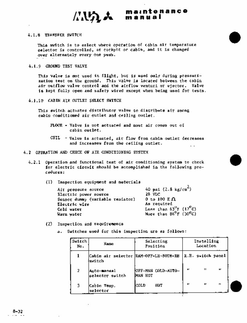
c~S´•rnl a I a f 8 a a a a a
n~snual
4.1.8 TRANSFER SWITCH
This switch is to select where operation of cabin air temperatureselector is controlled, at cockpit or cabin, and it is changedover alternately every one push.
4.1.9 GROUND TEST VALVE
This valve is not used in flight, but is used only during pressuri-zation test on the ground. This valve is located between the cabin
air outflow valve control and the airflow venturi or ejector. Valve
is kept fully open and safety wired except when being used for tests.
4.1.10 CABIN AIR OUTLET SELECT SWITCH
This switch actuates distributor valve to distribute air among
cabin conditioned air outlet and ceiling outlet.
FLOOR -‘Valve is not actuated and most air comes out of
cabin outlet.
CEIL Valve is actuated, air flow from cabin outlet decreases
and increases from the ceiling outlet.
4.2 OPERATION AND CHECK OF AIR CONDITIONING SYSTEM
4.2.1 Operation and functional test of air conditioning systemto check
for electric circuit should be accomplished in the following pro-
cedures:
(1) Inspection equipment and materials
Air pressure source 40 psi (2.8 kglcm2)Electric power source 28 VDC
Sensor durmny (variable resistor) O to 100 Kn
Electric wire As requiredCold water I Less than 630F (170C)Warm water More than´•860F (300C)
(2) Inspection and requirements
a. Switches used for this inspection are as follows:
Switch Selecting InstallingName
No. Position Location
1 Cabin air selector FF-LH-BOTH-RH R.H. switch panelswitch
2 to-manual OFF-MAN COLD-AUTO-II
selector switch HOT
3 ICabin Temp.selector COLD HOT I II
8-32

si~ a rr~:an’t ss P~ h C a
Ib~ ~ssa a (I
f~af th~ v~ilves are as in~i-i3cite~ sii at t~he positioii oft~i’e ab6´•t;k table; chE~Ck shoul~ bd
tifes respeetjldely for.each vblve;
c. OpeL~tidriai checic ~f engine bleed air shiitofji ~aive and Lamshutofr valve.
Nd. 1 Valve Position
Selbc’ting Eri~i:ne bleell~ air shutoff valire: Ram air Shutoff valve
Position LH RH
OFF ´•CLOSE CLOSE CLOSE
~CLOSE CLOSE OPEN
LH OPEN CLOSE CLOSE
BOTH OPEN OPEN CLOSE
RH CLOSE OPEN CLOSE
Cycle: OFF-RAM-OFF-LH-BOTH-RH-BOTH-LH-OFF
d. Operational check of refrigeration unit bypass valve
(i) Operational chec~ at MANUAL position
Switch No. 2
Selecting I Valve Position
Position
MAN COLD I FULL CLOSE
MAN HOT I FULL OPEN
Cycle´•: OFF-MAN COLD-MAN HOT-MAN COLD-OFF
8-33
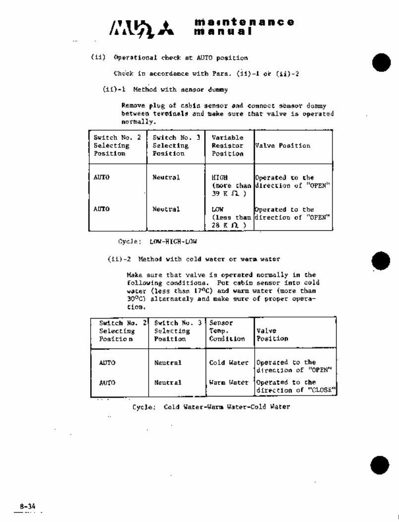
It iiii iB’I a t ci-,n a a cr eni a n a a I
(ii) OperBtioncil checkat AU~O position
i~hecli’in’accordance with Para. Tii)-~
~ii)-I Method with sensot dummy
Remove plug of c~bln sensor and connect s~nsor duhrmybetween terminals and make sure that valve is operatednormally.
Switch No. 2 Switch No. 3 Variable
~electing Selecting Resistor alve Position
Position Position Position
AUTO Neutral HIGH rated to the
(more than rection of "OPEN"
39 K R
AUTO Neutral LOW rated to the
(less than irection of "OPEN"
zs K´• n
Cycle: LOW-HIGH-LOW
(ii)-2 Method with cold water or warm water
Make sure that valve is operated normally in the
following conditions. Put ´•cabin sensor into cold
water (less than 170C) and warm water (more than
300C) ~alternately and make sure of proper opera-
tion
Switch No; 2 Switch No. 3 Sensor
Selecting Selecting Temp. Valve
Positio n Pdsition Condition Position
AUTO Neutral Cold Water Operated to the
direction of "OPEN"
AUTO Neutral Warm Water Operated to the
direction of "CLOSE"
Cycle: Cold Water-Warm Water-Cold Water
8-34

i n ii~ ;a sPOi ~Ei ii O e PI a iii ~i
;I
e. OpbrBtionaichi?d% or cooling ;uibine vaive
~i> Rer;ioi;e pliig o~ seti~6r and coiinect sensor
dummy’ (vari´•abl~ ´•yesistor and fixed resist~r eoi~riected~li ~ieri´•es2 bit~tween;jlug t~erntnaisi
~ii) Make’sure thatvalve is normally in thecondditt’oons.
Resistor PbSition Valve position
HI~H (lirdre thaii 9~ ~i(nj dperate~i to the dir~ctionof "OPEN"
LOW (mor~ than about: 74 Kn) I bperatea‘to: the directionof "CLOSE"
Bydl: LOW-HIGH~LOW
f. Operationalcheck of fan
Put circuit ~reaker "AIR COND"inand make sure that fan is
operated normally.
Z´• Operational-check of thermal switch
(i) Set switch Na. 1 to "BOTH"and make~.sure that LH~andRH engine´• bleed´•air solendid´•valves open.
(ii) Make’sure that "ACS.FAIL;" lamp illuminates and LHenginebleed air’:solenoid valve dloses when over-temp switch
circuit is shorted.
(iii) Release short-circuit.:and make sure that the above condi-
tions are.kept.
(iv) Turn circuit breaker ´•"AIR COND" off and set on again.Make;sure that LH enginebleed´•air solenoid valve
opens and ´•"ACS FAIL" lamp’goes out.
h. Operational check of pressure~switch
(i) Makesure that LH and RH engine bleed air solenoid-valves
~re open whenswjtch No.,l is in ~’BOTH"position.
(ii) Connect air pressure source to over pressure switchand
make sure that "ACS-FAIL" lamp illuminates-at 37 psi(2.6 kglcm2) ~and.LH engine bleed air solenoid valve
closes.
iiii); Reduce, pressure;’arid’make :suy~’ that-the above cond´•ftions
are pSi.
(iv) Tur~ cir’cuitbr~aker "AIR COND" off and.on again and
make sure that LH.engine’bleed´• air :solenoid valve opens
and "ACS-FAIL1 lamp’goes out.
(v) Turn switch No.l off.
(vi) Disconnect ~iir pressure source and´•restore the system.8-35
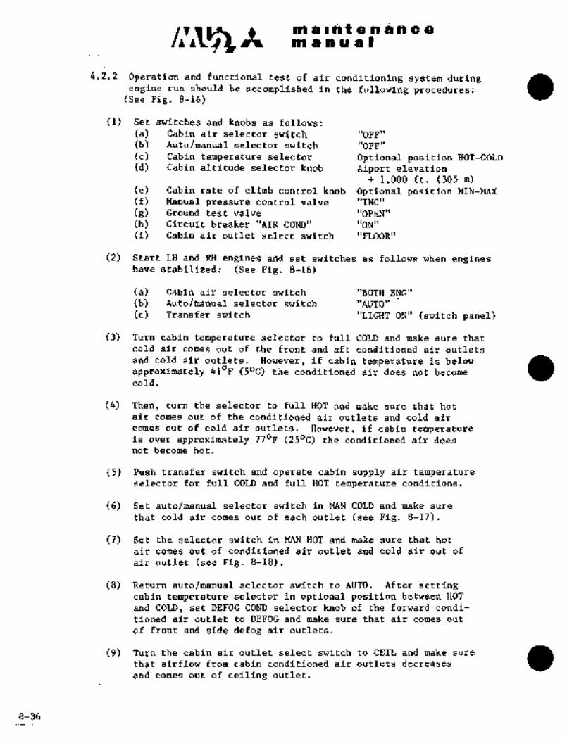
C~5Pa aPPif 8 .n h h a
nP anual
4.1.2 ~peration and functional test of air conditioning system duringengine run should be accomplished in the following procedures:
(See Fig. 8-16)
(1) Set switches and knobs as follows:
(a) Cabin air selector switch "OFF"
(b) Auto/manual selector switch "OFF"
(c) Cabin.temperaturP selector. Optional position HOT-COLD
(d) Cabin altitudeselector knob Aiport elevation
1,000 ft; (305 m)(e) Cabin rate of climb control knob Optional position MIN-MAX
(f) Manual pressure control valve "INC"
(8) Ground test: valve "OPEN"
(h) Circuit breaker "BIR COND" "ON"
(i) Cabin air outlet select switch "nOOR"
(2) Start LH and RH engines and set switches as follows when engineshave stabilized: (See Pig. 8-16)
(a) Cabin air selector switch "BOTH ENG"
(b) Auto/manual selector switch "AUTO"
(c) Transfer switch "LIGHT ON"(switch panel)
(3) Turn cabin temperature selector to full COLD and make sure that
coldair comes out of the front and aft conditioned air outlets
and cold air outlets. However, if cabin temperature is belowOF (50C) the conditioned air does not becomeapproximately 41
cold.
(4) Then, turn the selector to full HOT and make sure that hot
air comes out of theco’nditioned air outlets and~cold air
comes out of cold air outlets, However, if cabin temperatureis over approximately 770F (250C) the conditioned air does
not become hot.
(5) Push transfer switch and operate cabin supply air temperatureselector for full COLD and full HOT temperature conditions.
(6) Set auto/manual selector switch in MAN COLD and make sure
that cold air comes out of each outlet (see Fig. 8-17).
(7) Set the selector switch in MAN HOT and make sure that hot
air comes out of conditioned air outlet and cold air out of
air outlet (see Fig. 8-18).
(8) Return auto/manualselector switch to AUTO. After settingcabin te~perature selector in optional position between HOT
and COLD, set DEFOG COND selector‘knob of the forward condi-
tioned air outlet toDEFOG and make sure that air comes out
of front and side defog air outlets.
(9) Turn the cabin air outlet select switch to CEIL and make sure
that airflow from cabin conditioned air outlets decreases
and comes out of ceiling outlet.
8-36

a r,ii t a ´•n $n a a
m a i~i a a 1
(iO) Set cat~in air seleCtor switch in RAMpositibn and make sure
that ram 8ir comes out of conditioned ait outlets (seelFig.8-i9). However, the Of ram air during ground opera-
tion is not ~sufficient; therefore, the opening~ and closing
ope~ation of ram air shutpff valve and other valves of thisl
system should be checked thoroughly.
(11) Return switches and knobs to OFF or their original positions,and stop engines.
AIR CONDCABIN Al
aOTH E/ AUTO CONT/´• AUTOLH RH MAN I 1( MPN
OFF
COLb
COLD ~-u( HOT
"ii’0 ra OHOT
RAMPVSH FOR. TEMP CONT 2
.CABIN AIR OUTI.ET dcs FAILURE CI.IH PREQSURC 7CEIL
6RATE o
tOll~ROL
QCABINFLOOR
MAN PRESS CONT ALT.
I:RTP::FEDIC~T
DEC~ 8: INe tf w lLI
21 006
7. 84 5 6 9
i. Cabin air selector switch
2. Cabin supply.air temperature switch
3. Auto-manual selector switch
4. Cabin air’ outlet select=switch
5. Transfer ’switch
6. Manual predsure control value.
7. Cabin rate of cl~imb knob
8. Cabin altitude select switch
9. Air Conditioning System Fail Warning Light(S/N 652SA and 661SA)
Eig..8-16 Air Conditioning and Pressurization Control Panel
Key to Figures 8-17,8-18, 8-19 and 8-?0
i. Engine bleedair shutof~.vlave .7. Prifnarqr heat exchanger
2. Ram air shutoff valve´• 8.. Secondary heat exchanger
3.’Refrigeration unit bypass valve 9. Air discharge port
4. Cooling turbine bypassval.ve -’10. Coalescer
5, Cold´•air intake& screen:.´• 11. Water´•aspirator
6. Precoo~er It.Ramair;intakepott’ 8_3,j:..9

nl a ~i, ii t t;i -a a Pi C BE
an a ii a a I
/1U)U) AIR
I t gcoNniTlcmn AIR
Y 7
tOU) HOTY
O\BIN AIR
LENGBOM EN6’" O‘4
RAW
.10
I1AnAUTO
HAH 1tOU1 HOT ‘11 11
OFF
/1//1
21 WIS
Fig. 8-17 Air Supply Temperature Control Condition
12
U)U) AIR
HOT A~R f i -~6UU)IA AIR ~J 7
BOTH EHG
LD(6,a12~RDlti Y
RAW
2
AUTOaN rYIW
HOT
10
COU) Il
OFF 8
1
11
5~ 21 004
Fig. 8-18 Manual Heating Condition
8-38
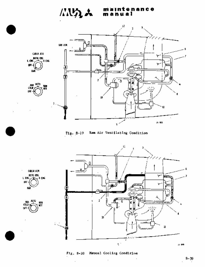
ni ii; li~ a I
12
i
´•RAn AIR fCABIN AIR
´•BOTH ENGL
Y
WV~
H :1 2AUTO 4MAN IYW
HOTCOLD
OFF
1.
11
///I/
21 003
Fig.:8719 Ram Air Ventilating ~Conditibn
123
D tCABIN AIR
BOTH ENG- YR ENGL ENG
OFF
RAM
2MAN AUTO
OFFMANCOLD HOT4
ilr \210
1
´•1l
5 21 00B
Fig, 8-20 Manual Cooling Condition
8-39

Cllr;5 A m a a a a)
4.i TROUBLE SHOOTING CABIN AIR COM)ITIONING SYSTEM
Tro~ble I Probable cause Remedy
Eo~ine compressor bleed a. Engine bleed air shut- i. Check electrical circuit.
air is not available (or off valve cannot be ii. Replacevalve (when valve
quantity of bleed air is opened. is faulty.too low)
b. Engine bleed air check Replace valve.
valve cannot be
opened.
c. Bleed air tubing´• i. Ch‘eck bleed air tubing.defective. ii. Replace faulty components.
d. Ram air shhtoff valve i. Check electrical circuit.
not fully closed. ii. Replace valve (when valve
is faulty).
Engine compressor bleed a. Engine bleed air shut- i. Check electrical circuit.
air cannot be stopped off valve cannot be ii. Replace valve (when valve
closed. I is faulty).
Heating air cannot be a. Temperature control i. Check electrical circuit.
obtained I defective. ii. Check each component and
replace faulty units.
’Ib. Refrigeration unit by- i. Check electrical circuit.
pass valve cannot be ii. Replacevalve (when valve
opened. is faulty).
Cold air is not a. Temperature control i. Check electrical circuit.
obtained defective. ii. Check each component and
replacefaulty units.
b. Refrigeration unit by- i. Check electrical circuit.
pasS´•valve cannot be ii. Replace valve (when valve
closed. I is faulty).
c. Cooling turbine bypass i. Check electrical circuit.
valve cannot be ii. Replace Valve (when valve
closed. I is faulty).
d. Cooling air intake or Remove obstacle.
outlet is blocked.
e. Operation of refrige- I i. Replace unit.
ration unit is faulty-. J~´•ii. Tty tb turn the fan blades
bya non-metallic probe.
Ram air ventilation la. Ram air shutoff valve i. Check electrical circuit.
can not~be accom- I cannot be opened. ii. Replace valve (when valve
pl~shed I is faulty).
b. Ram air intake is Remove obstacle.
blocked.
8-40

It aP 811 nr ts Il ct II
m a.n a a I
Trouble Probable cause Remedy
Cabin air temperature la. Cabin supply air tem- Replace sensor.
fluctuates perature sensor does
not work normalljy.
b. Cabin air temp. I Replace control.
control does not
work normally.
c. Refrigeration unit I Replace the unit.
does not work normally.
Temperature cannot be a. Cabin air temp. con- Replace the control.
controlled when auto- trol doesnot work.
manual selector isb. Cabin supply air tem- Replace sensor.
placed in "AUTO"perature sensor does
not work normally.
Very hot air flbws out a. High temperature Replace limit switch.
when auto/manual I limit swi´•tch does not
selector is placed in I work normally.MAN HOT
b. Operation of relay is I Replace relay.faulty.
c.. Refrigeration unit by- Replace valve.
pass valve does not
work normally.
Cabin supply air a. Operation of water Replace sensor.
contains too much separator inlet air
moisture, or carries I temp. sensor is
ice flakes I faulty.
b.. Operation of water Replace regulator.separator inletair
temp. control is
faulty.
c. ’Condenser in water I Replace water separator.
separator .is blocked
with dirt, oil, etd.,so bypass valve opens.
Air does not come out a. Rotary section of the i. Disassemble the valve
.of ceiling outlet when valve interferes with I and adjust not to
cabin air outlet select fixed sectioni interfere;
switch is turned tob. Rotary solenoid does i. Check electric circuit.
CEILnot work. ii. Replace rotary solenoid
c. Ceiling outlet or I i. Remove obstacle.
tubing is blocked.
fACS FAIL light I a. Operation ´•of engine I Replace pressureilluminates bleed pressure regu- regulator.
later isblocked.
BRBB~$NAL p~s /b. Operationof cooling Replace air cyclefan’is faul.ty. machine.
RECEI$EDBYY~P lc. Cooling air systemisblocked.
Remove obstacle.
8-41

C~jS m a int-a a an a a
m.a a a a I
4.4 OPERA~IONAL CHECK OF CABIN PRESSURE CONTROL SYSTEM
(1) Start engines per AIRPLANE FLIGHT MANUAL and stabilize at 100% rpm and
50% torque (condition lever; takeoff-land; power lever torque 50%).
(2) Set air conditioning and pressurization controls as follows:
Cabin supply air selector BOTH
Auto/manual selector AUTO
Cab-in altitude selector Field elevation -1,000 ft.
Cabin rate-of-climb control Adjust the arrow mark on knob
to calibrated mark
.Ground test valve OPEN
Cabin Temp control As desired
Manual pressure control valve FULL INC
DOOR SEAL circuit breaker Closed
(3) ~When the airflow volume into the cabin has stabilized, check the
differential pressure indicator; the value should be approximately 0.5 psi.
(4) After confirming the differential pressure, set the controls as follows:
Manual ´•pressure control valve FULL DEC
Ground test valve CLOSE
(5) Turn manual pressure control valve to FULL INC position. Note the
following:
Differential pressure 4.80 to 5.25 (*1)5.80 to 6.10 (*2)
Cabin rate-of-climb Up approximately 300 ft/min.Outflow safety valves Functioning normally
\NARNIN
Should the differential pressure exceed
the maximum limit, decrease the cabin
pressure by turning the manual pressure
control toward decrease. Shut down all
systems and locate c~use for cabin over-
pressurization.
The differential pressure should not fluctuate.
"1 Aircraft S~N 652SA
*2 Aircraft S/N 661SA, 697SA and subsequent
4
8-42

:no ii~ s:hl’t.lai3B i~ ~i i~i a s
The contltol~valveL(ilC)f C~
equlres;6.0 to6.5 ’turns frommnfi ~NC
to RiLL D~C. The cabin will inlc~ease rapidly the i~st 1 to ~S tiirn bef´•or~ILNt: poSiti6n, ~o iralve operation ~holi/ld be
ca~efully performed i
(6) Turn the. inanual ~ontrol valve ~rom FULL INC to FULL DEC
gra&uaiiy. ~iedabin r$te-oi-cl’imb indicator shou~d indic~ite Down
approxiinately 4,‘000 jit/min. and the dif’feirential pressure indicatorshb´•i~ld iti’dicate "0" (zero).
(7) set thh cabin alrit~ide selector to "O" (zero) feet and the
pressurecontrol valve to FiTLL INC.
(8) AdJ’ust each engine rpm to ground idle.
(9) Set all air-conditioning and pressurization contirols as hescribed in
paragraph (2) except the~cabin altitude selector, which should be
set to´•"O" (zero) feet.
(10) Shut down engines per AIRPLANE FLIGHT MANUAL.
(11) Open the ground test valve a~d installsafety wire.
4.5 CABIN PRESSURE LEAKAGE TEST.AND OPERATIONAL CHECK FOR OUTFLOW SAFETY
.VALVE.
(1) Disconnect conditioned air tube and cold air tubeon the side of the
rearbulkhead (F.STA 8035),9n~’plug tube ends bn.bulkhead side.
Plug-vacuum line for gyro. Pull ~ut circuit breaker LDG.’POS IND’
(2) Disconnect atmospheric pressure seasingtubes of outflow safety valves
and plug the’two unions.
(3) Remove RH lower access panel at STA 1080 and plug atmospheric portof venturi (k´•l). Optionally select positions for cabin altitude
selector knob, and cabin rate of climb control´•knob.
(4) Set ground t~est valve lever to CLOSE located at right side front of
co-pilot pedal.
(5) Close circuit breaker DOORSEALand actuate selecor:valve for
entrance door seal..
(6) Connect pressurizer to the ´•poi-t:(STA~ 1080 bulkh~ead, LH).for pressure
testand piressure bensing line to sensing.portSTA 1080 bulkhead, RH)respectively.
Aircraft S/N 652~A
8-43

´•1C m aiiltenLne ti
m anual
(7) (*1) Increase airpressure in pressurizer gradually and-stabilize
at 5.0f 0.1 psi. Leakage should be less than 70 cu. ft/min.; shouldthis limit be exceeded, seal the leaking points.
(*2) Increase airpressure in pressurizer gradually and stabilize
at 6.0 0.1 psi. Leakage should be less than the value shown in
Fig. 8-24. Should the limit be exceeded, seal the leaking points.
(8) After confirming Para. (7), reduce pressure and recon~ect atmosphericpressure sensing tubes, of outflow safety valve to normal tubing. Then,
pressurize cabin again and check for pressure relief at 5.0 +0.25/-0.10
psi ("1), 6.0~f 0.1 (*2) psi. If relief does not work when air pressure
is increased up to 5.35 psi ("1), 6.1 psi (n2), outflow safety valve
is defective. Replace it.
(9) After completion of test,restore airplane to original´•condition.
CAUTION
After test, set ground test valve ~to
full open position (valve handle is
parallel to tube), and appIy lock wire.
78
77
76
75
LEAKAGE 74
CFM
73
72
’71
70
-10 0 10 20 30 40
PRESSURIZED CABIN AIR TEMPERATURE ’C
Allowable leakageof pressuri´•zed cabin
*1 Aircraft S/N 652SA
*2 Aircraft S/N 661SA, 697SA and subsequenf
8-44

~ii i i iii iLi ´•ii ~i) liit:~nii ~a ii U a I
4.~ SHOOTING CAjBf~ PRES~UkE 60~JTROL
Trouble Probable cause Bem~dy
cannbt ~e leakage ~rom airplane I Repair defective
ob tained I i~ excessiire~ ’I seal.
b. Fo~eign matter ai3cu- ~I Remove foreignmulated on valve r~tter.
poppet Seat.
c. Cabin altitude selector Reset at desired
knob is not set gltitude.
properly.
d. Cabin pressure air Replace control.
outflow valve control
is faulty.
e. Outflow´•safety valve Replace valve.
is defective.
f. Air supply to cabin I Check supply air
is low. system for tube
damage, ´•defective
connections, etc.
g; ´•Manual pressure Close valve (tocontrol valve is open. I~ IMC direction).
h. Pneumatic relay is Replace relay.faulty.
Cabin pressure is J´•’.a. Tube connections be- I Tighten loose
higher than selec~ted I tween cabin air out- I connections.
flow valve control
and outflow ~afetyvalve are loose.
b. Outflow safety valve Replace valve.
is defective.
c. Internal defect of I Replace control.
cabin air outflow
valve control..
d. Pneumatic relay is I: Replace control.
´•defective.
Selected cabin alti- Tribe connection be- I Check ttibing and
rude cannot´•he;main- I tween, cabin a5r~out- I ~tighten loose
tained I flow valve control I connections.
and ~outflow safetyvalve is faulty.
8-45

c~sCn a i a i 8 a ii 8 C: a
mainQa)
Trouble Probable cause I´• Remedy
b. Cabin air outflow valve Replace valve.
control is faulty;
c. Outflow safety valve is Replace valve.
faulty.
Maximum differential a. Outflow safety valve Replace valve.
pressure exceeds is faulty.limit
b. Connection of static Tighten loose
tube of outflow safety connection.
valve is faulty.
c. Cabin altitude and Replace gauge.differential pressure
gauge is faulty.
Manual pressure a.. Manual pressure con- I Replace valve.
control cannot be I trol valve is faulty.performed properly
b. Tube between manual Tighten loose
pressure control connection. If
valve and jet pump blocked, remove
venturi or ejector I obstacle.
is loose or blacked.
Cabin pressure varies I a. Water separator tem- Replace controller
perature controller or sensor.
or its temp. sensor
is at fault.
b. Water separator is I Check the bag for
faulty. contamination and
clean or replaceif necessary.
c. Cabin temp. control- Replace controller.
system is faulty.
8-46

It ~allnte aaa a a
Hn sa~n a a I
5. AIR SUPPLY SYSTEM
5.1 GENERAL DESCRIPTION
This systeflconsists of tubing, flexible tube assembly and pressure control
valve, and supplies air to the surfacede-icer system, windshield anti-icingsystem (if installed),:- cabin pressure control system, entrance door sealingsystem, tip tank fuel transfer system, vacuum system and autd-pilotsystem.
The compressed hot air from the last stage of the L. H. and R. ii. engine compres-
sors is led to the fi~selage through the lines in the wing trailing edge, regulated bythe pressure regulator to a constant pressure and divided to each system.The check valves installed inthe lines in the wing are to prevent the reverse flow
.of hot air’from the operatingenginB into the compressor of the~dead engine,shduld one engine become inoperative.
This system is ´•Sufficient to supply air to each system even if one engine is
inoperative. (See Fig´•. 8-2i)
5.2 VALVE (18 PSI) (See Pig. 8-22)
This valve regulates engine bleed air, air source for the ejector u´•hich producesgyro driving vacuum, to 18 psi. (1.3 kg/ cm). This valve also has a pressure
relief function, and it works when the valve outlet pressure exceeds 20 psi. (1.4 kgjcm’).5.2.1 REMOVAL AND INSTALLATION
(a) Remove center wing rear access door.
(b) Remove tube assembly, upstream and downstream of the valve.
(C)~ Remove four screws from the valve
attaching bracket and remove valve.
(d) Remove reducer and union upstreamand downstream of valve and cap
valve ports, 7´•
(e) Install in reverse secluence of
removal.
ORIGINAL ~i .i
As Received ByAT P
Pig. 8-21 Pressure control valve
5.3 PRESSURE CONTROL VALVE (15 FSI)
This valveregulates engine bleed air, air sources for the surface de-icer
system, windshield anti-icing system (If installed), cabin pressure control
system, entrance door sealing system and tip tank fuel transfer system, to
15 psi (1 kg/cm2).5.3.1 REMOVAL AND INSTALLATION
$ea ChapterIX, Para. 2; 2. i.
4-1-78 8-47

maintenancemanual
TEMPORARY REVIS16N N0.81elThis Temporary Revision No. 8-1 is applicable to the following Maintenance
Manuals
MODEL NO. REPORT NO. PAGE
MU-2B´•351-36A MR-0218 8-47
MU´•2B-60 MR-0336 8-47
Insert facing the page indicated above for the applicable Maintenance
Manual.
Retain this Temporary Revision until such time as a permanent revision on
this subject is issued.
REASON To add Tubing Inspection and Repair.
ADD Paragraph 5.4 as follows.
5.4 TUBING INSPECTION AND REPAIR
5.4.1 PREPARATION
(1) Remove access panels and equipment as required to gain access to the pneumdtic
line to be inspected as shown in Figure 8-22A.
(2) Remove all lines supporting clamps identified on the figure and retain these clamps
and attachment hardware for reinstallation.
5.4.2 INSPECTION
(1) Visually inspect the clamped surface of the pneumatic lines for any signs of corrosion.
Use a mlrrorand flashlight to check the entire periphery surface of clamp attachment
area.
a. If inspection does not reveal corrosion damage (slight oxidized material without
pitting or discoloration is acceptable), it is acceptable to.reus. Proceed to section
5.4.3 for surface refinish.
b. If inspection does reveal corrosion damage, remove and replace the tube assembly.
Proceed to section 5.4.4 for local fabrication of replacement tube assembly.
(2) Visually inspect the clamp for signs of corrosion, burning, hardening, or absence of
the rubber gasket. Remove and replace the clamp with a new one as necessary.
NOTEUnauthorized clamps, especiallysteel clamps, are
susceptible to galvanic corrosion and cbuld caGsea loss of pressurization, pneumatic air, andlor surfacedeice systems.
TEMPORARY REVISION NO. 8-1
Page 1/6
MU-2B-35, -36A, -60 Jun.16/2003

ma~intenanceman ual
TEMPORARY REVISION N0,81~
(3) Visually inspect each clamp removed from the aircraft and verify the usage of the´•
correct part number that is specified in figure as applicable.
5.4.3 SURFACE REFINISH OF TUBE ASSEMBLY
The following steps are applicable to the all tube assemblies that are confirmed
serviceable after the inspection in Paragraph 5.4.2.
Before restoring plumbing of thess pneumatic lines,.treat the clamp contact area on
the tube assembly as follow.
NOTEUse only fine grade sandpaper #400 with aluminumoxide or silicon carbide sandpaper.No other material is permitted.
5.4.3.1 For Electrical Bonding Surface (See Note-b in the figure 8-22A)
Remove Ilght corrosion and deposits from the contact area of the bonding clamp by
sanding with fine #400 sandpaper as shown in Figure 8-228.
(2) Clean all sanded surfaces with Methyl Ethyl Ketone, TT-M-261.
NOTEDo not disturb the treatment surface.Avoid contact´•with body oils or acids which may cause
corrosion or prevent adhesion of alodine film.
(3) Apply alodine #1200, chemical film.
(4) Keep the treated area wet for approximately 3’to 5 minutes until a yellow color
develops.
(5) After the alodine has changed color, rinse the area with a wet cloth and
blow dry with shop air.
5.4.3.2 For Non-Bonding Surface
The clamp attachment positions where the top coating exhibits light corrosion
andlor peeled paint appearance, treat the surface per following steps.
(1) Thoroughly sand the area of the damaged´• coating with fine #400 sandpaper.
(2) Clean all sanded surface with Methyl Ethyl Ketone, TT-M-261.
NOTEDo not disturb the treatment surface.Avoid contact with body oils or acids which may cause
corrosion or prevent adhesion of alodine film.
(3) Apply alodine #1 200, chemical film, to area of exposed metal.
(4) Keep the treated area wet for approximately 3 to 5 minutes until a yellow color
develops.
TEMPORARY REVISION NO. 8-1
Page 2/6MU-2B-35, ´•36A, -60 Jun.l 6/2003

c~inmaintenancemanual
TEMPORARY REVISION N0.81~
(5) After the alodine has changed color, rinse the area with a wet cloth and
blow dry with shop air.
(6) Touch-up with one coat of zinc-chromate primer TT-P-1757.
5.4.4 FABRICATION OF TUBE ASSEMBLY
Replacement tube assembly may be locally fabricated per the following steps.
(1) Refer to the Table 8-1 in order to prepare parts and material for tube assembly.
(2) Cut and form the tube to fit with actual mold made from the existing tube assembly.
(3) Instail the coupling nuts (2 ea) and sleeves (2 ea) before flaring the tube ends.
(4) Make single flare at both ends of tube per MS33584.
(5) Degrease and flush tube using Methyl Ethyl Ketone, TT-M-261.
(6) Cap or mask both ends of tube to prevent contamination.
NOTEDo not disturb the treatment surface.Avoid contact with body oils or acids which may cause
corrosion or prevent adhesion of alodine film.
(7) Apply alodine #1200 solution with a brush to the entire external surface of the tube
assembly. Keep treated area wet for approximately 3 to 5 minutes until a´• yellow
color develops.i j
(8) After the alodlne has changed color, rinse the surface with water and blow dry with
shop air.
(9) Mask off all contact surfaces of the bonding clamp contact area 1-1/2 times the
clamp~width as shown in Figure 8-228 preparation of electrical bonding surface.
(Refsr to mark in Figure 8-22A for the location of ground bonding)
(10) Mask off external surface of both ends of tube approximateiy 1 inch from the end of
tube.
(11) Apply one coat of zinc chromate primer TT-P-1757 with brush to the exterior surface
of tube assembly.
(12) Remove masking tape.
TABLE 8-1 TUBING MATERIALAND END FITTINGS
TUBE MATERIAL OUTER COUPLINGTHICKNESS SLEEVE
ASSEMBLY SPEC. DIAMETER NUT
5052-0 tube AN818-10D MS20819-10D030A-64304-17 5/8 inch dia. 0.035 inch
-T-700/4 2ea 2ea
5052-0 tube AN818-10D MS20819-10D030A-64304-67 5/8 Inch dla. 0.035 inch
-T-700/4 2ea 2ea
TEMPORARY REVISION NO. 8-1
Page 3/6MU-2B-35, -36A, -60 Jun.l 6/2003

C~5, ftmaintenanceman ual
TEMPORARY REVISION
5.4.5 RESTORATION
(1) Restore the serviceable or fabricated tube assembly.
(2) Reinstall ail line supporting clamps that were removed in section 5.4.1 for inspection.
Sand and clean all contact surfaces on the clamp with a suitable solvent before
installation.
5.4.6 LEAK TEST
Perform the pneumatic system leakage test to ensure proper restoration of the
reinstalled tube assembly as follow.
(1) Disconnect pneumatic line at the location as shown in the applicable figure.
(2) Connect air pressure source to the system and supply air pressure gradually and set
at 100 psi.
(3) Check for leaks from the line connections while air pressure is applied.
(4) Disconnect pressure source and restore the system.
TEMPORARY REVISION NO. 8-1
Page 4/6
MU-2B-35, -36A, -60 Jun.l 6/2003

maintenancemanwal
T~MPOFZARY RIVISION N0.8-~
7
CLAMP´•(155-10-2-8)3 PLCS /iATTACHMENT HARDWARE (REF)
AN520-10R8 SCREW(3ea)NAS679A3W NUT(J ea)
~jS
~Ei j
\\U
030A-64304-11
CLAMP (MS21919DG10)1 PLC
ATTACHMENT HARDWARE (REF)AN52Q´•10R12 SCREW(lea)NAS43DD3-25 SPACER(?ea)NAS679A3W NUT (1 ea)
DISCONNECT LINE HERE
FOR LEAK TEST
(REF PARA.5.4.6)
NOTE
a Remove all the clamps depicted in this figure and inspect the clampcontact surfaces on the tube assembly and the clamps.(Ref. Paragraph 5.4.1)
b Clamp position Identffied the special clamp positionthat function as an electrical bdnd and requires bonding surface
treatment at the clamp attachment position on the tube assembly.(Ref. Paragraph 5.4.3.1, 5.4.4( 9) and Figure 8-228)
Flg. 8-22A Inspection Areas
TEMPORARY REVISION NO. 8-1
Page 5/6
MU-28-35, -36A, -60 Jun.18/2003
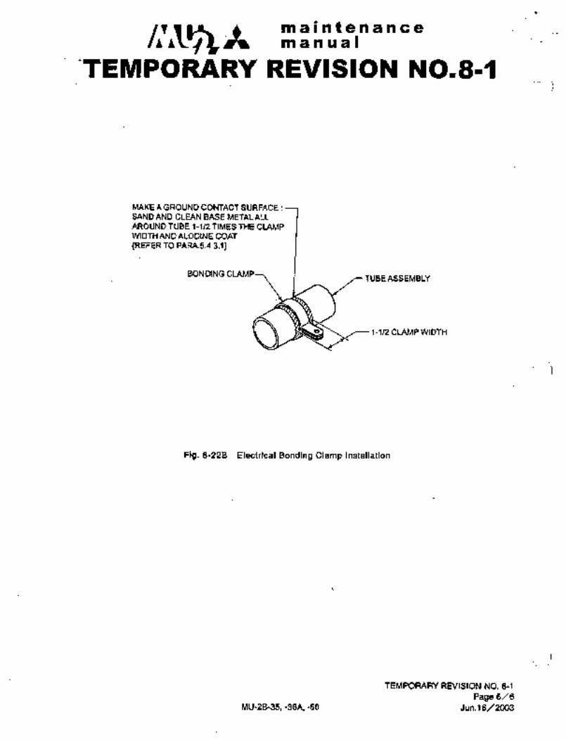
n maintenancemanual
TEMPORARY REVISION N0181~
MAKEAGROUNDCOMACTSURFACE:SAND AND CLEAN BASE METAL ALL
AROUND TUBE 1-1!2 TIMES THE CLAMPWI DTH AND ALODINE COAT
(REFER TO PARA.5.4.3.1)
BONDING CLAMPTUBE ASSEMBLY
~I ~--1-112 CLAMPWIDTH
Pig, 8-228 Electrical Bonding Clamp Installation
TEMPORARY RNISION NO. 8-1
Page 6/6
MU-28-35, -36A, -60 Jun.l 6/2003

03
E-00
i. Engine bleed air port~ae lligh pressure line lair supply system)
2. Checkvalve nmr 15 psi line
3. Regulator reliefvalve ~-LSL´• 8 PS1 line
Vacuumline4. Manifold
5. Shutoff valve 15psi&vacuumline
6. Regulator valve i~Lea Otherline
7. Controlassembly 18 psi line CI,
r/ )i8. Anti-icer fluid tank
N~ail.
1D1 Jet pump venturi
11. Marmal pressure
control valve
12. Outflow valve controller
13. Filter i j14. De-icer timer
15. Ground testvalve Db"16. Airflow venturie---~\11 r"~-J17. OuMow safety valve
18. Pneumatic relay19. Pressure suitch
asi´• I,2 r-i
I,
/j g)~ pp
L_i 1
i ’,O 18ee
.,z
A/P 9, ggis’ i;~l 13~ (1
313
igist
2fi1~.
9
:1
1,
,~48 /i 3 28iii] L---d Cb
(P
j 2020. Checkvalve
21. Selectorvalve
22. I~oor seal
23. Ejector 31. Entrance door pressure iock
24. Relief valve mechanism
25. Gyro26. Filter
27. Distributor valve
28. Pressure switch
29. Screen and orifice
30. Windshield anti-ice timer Fig. 8-22 Air pressure system(If installed)
r
D3

CHAPTER
ANTI-ATNIOSPHERICSYSTEM

maintenancemanual
CHAPTER IX
ANTI-ATMOSPHERIC SYSTEMS
CONTENTS
1. GENERAL 9- 1
2. SURFACE DE-ICING SYSTEM 9- 1
2.1 GENERAL DESCRIPTION 9- 1
2.2 PRESSURE REGULATOR AND RELIEF VALVE 9- 1
2.3 MANIFOLD 9- 4
2.4 DISTRIBUTOR VALVE 9- 6
2.5 EJECTOR 9- 6
2.6 TIMER 9- 7
2.7 PRESSURE SWITCH 9- 7
2.8 RUBBER BOOTS 9- 7
2.9 OPERATIONAL CHECK 9-8-1/9-8-2 I2.10 TROUBLE SHOOTING SURFACE DE-ICING SYSTEM 9-10
3. WINDSHIELD ANTI-ICING SYSTEM 9-11
3.1 GENERAL DESCRIPTION 9-11
3.2 HEATED WINDSHIELD ANTI-ICING SYSTEM
(Aircraft S/N 661SA, 697SA and subsequent) 9-17 I3.3 FLUID ANTI-ICING SYSTEM
(Aircraft S/N 652SA and Aircraft equipped with system) 9-22
4. WIPER 9-22
4.1 GENERAL DESCRIPTION 9-22
4.2 REMOVAL A~ INSTAUATION OF WIPER MOTOR .9-22A(B) I4.3 REMOVAL AND INSTALLATION OF CONVERTER 9-23
4.4 REMOVAL AND INSTALLATION OF WIPER BLADE 9-25
4.5 ASSEMBLY AND ADJUSTMENT OF WIPER SYSTEM 9-25
4.6 TROUBLE SHOOTING 9-31
5. DEFOGGING SYSTEM 9-32
5.1 GENERAL DESCRIZYTION 9-32
3-31-90 9-i

c~ Itmaintenancemanual
5.2 WINDSHIELD DEFOGGING 9-32
5.3 CABIN WINDOW DEFOGGING 9-32
5.4 TROUBLE SHOOTING OF DEFOGGING SYSTEM 9-34
6. ENGINE AIR INTAKE ANTI-ICING SYSTEM 9-(35)36
6.1 GENERAL DESCRIPTION 9-(35)36
6.2 ANTI-ICING BLEED AIR VALVE 9-(35)36
7. PROPELLER DE-ICING SYSTEM 9-39
7.1 GENERAL DESCRIPTION 9-39
7.2 TIMER 9-39
7.3 BRUSH BLOCK AM) SLIP RING 9-41
7.4 DE-ICER 9-43
7.5 OPERATIONAL CHECK OF TIMER 9-44
7.6 OPERATIONAL TEST OF PROPELLER DE-ICING SYSTEM 9-44
7.7 TROUBLE SHOOTING PROPELLER DE-ICING SYSTEM 9-46
8. PITOT AND ANTI-ICING SYSTEM 9-47
8.1 GENERAL DESCRIPTION 9-47
8.2 MAINTENANCE PRACTICES 9-47
8.3 TROUBLE SHOOTING 9-48
9. STALL WARNING ANTI-ICING SYSTEM 9-50
9.1 GENERAL DESCRIPTION 9-50
9.2 REMOVAL AND INSTALLATION OF LIFT TRANSDUCER 9-50
9.3 OPERATIONAL CHECK OF LIFT TRANSDUCER 9-51
9.4 TROUBLE SHOOTING 9-51
10. OIL COOLER AIR INLET ANTI-ICE SYSTEM 9-52
10.1 GENERAL DESCRIPTION 9-52
10.2 ANTI-ICER 9-52
10.3 THERMOSTAT 9-52
10.4 OPERATIONAL CHECK 9-53
10.5 TROUBLE SHOOTING 9-53
I S-ii 3-31-90

a~9 a 61~1ati ~a ce ~p8n bD 8 IB
i; DEruead (ri8´• 9-1)
A p’~eumati.e .i-iibber :boot de-~ic.ing ~yF;tem iS instlied~ on ´•tHE~ wi~g’eag’eg’. Electiicalljr heated i;;
systemsanti-ice ana ae;lce
are utilized components which are pitot tube, static port,´•Stail warnilig´•lift transduc’er, prbpellers, wirid$hi~elds a~d oil i~ooleirair inl~fs; The engi~e ait int~ke by n~eans of engine
i~dinpress0r ~leed gir. Cabin air is Suppiied´•tbali windowsroi: ciefogging between the dou~le window pan~s; A wiper is provided for
remo~ial oi~ rain and slJsh ice from the windshields.
2, SURFACE SYST~M (Fig. 9-2)
2.1 ~ENERAL DESCRIPTION
De-icing.of thewing and empennage leading edges is accomplished byinflating and deflating rubber boots attached to the leading edges.The system consists of a pressure regulator and relief valve, mani-
fold, distributor valve, ejector, timer and required tubing.
When the WING DE-ICE switch in ´•the overhead console is placed to the ON
position, a timer is energized and the pressuriiarion port of the dis-
tributor valve is opened in response to thetimer signal, thus allowingair pressure ´•to inflate the boots causing ice removal from the leadingedge surfaces. A pressure switch is installedin.the tube to the
wing boots causing an indicator light in the overhead console to illu-
minate. Deflation occurs when the timer signals the distributor valve
to close the pressure port and open the negative pressure (suction) and
exhaust ports. During automatic operation, cycle time of inflation and
deflation is approximately three minutes, but manual control can shorten
the cycle to 16 to 18 seconds. ´•When the switch is in the OFF position,the pressurizationand exhaust ports are inthe closed position and the
negative pressure (suction) port is open. The negative~ pressure (suction)is connected to the ejector, causing a´•negative pressure in the de-ice
boots, so that the boots do not inflate during flight.
2;2 PRESSURE REGULATOR‘ AND RELIEF VAI~VE (Fig. 9-3)
Enginecomp’ressor bleed airis theair source for the surfacede-icingsystem, and is’regulatedatl5 psi (1.1 kg/cm2)by this valve. Regu-lated air flowstothe distributor valve’for pressurization and ejectorfor high pressure air source. The vaivealso has a pressure relief
function,should the outletpressure exceed 17.5 psi (1.2 kg/cm2).
9-1
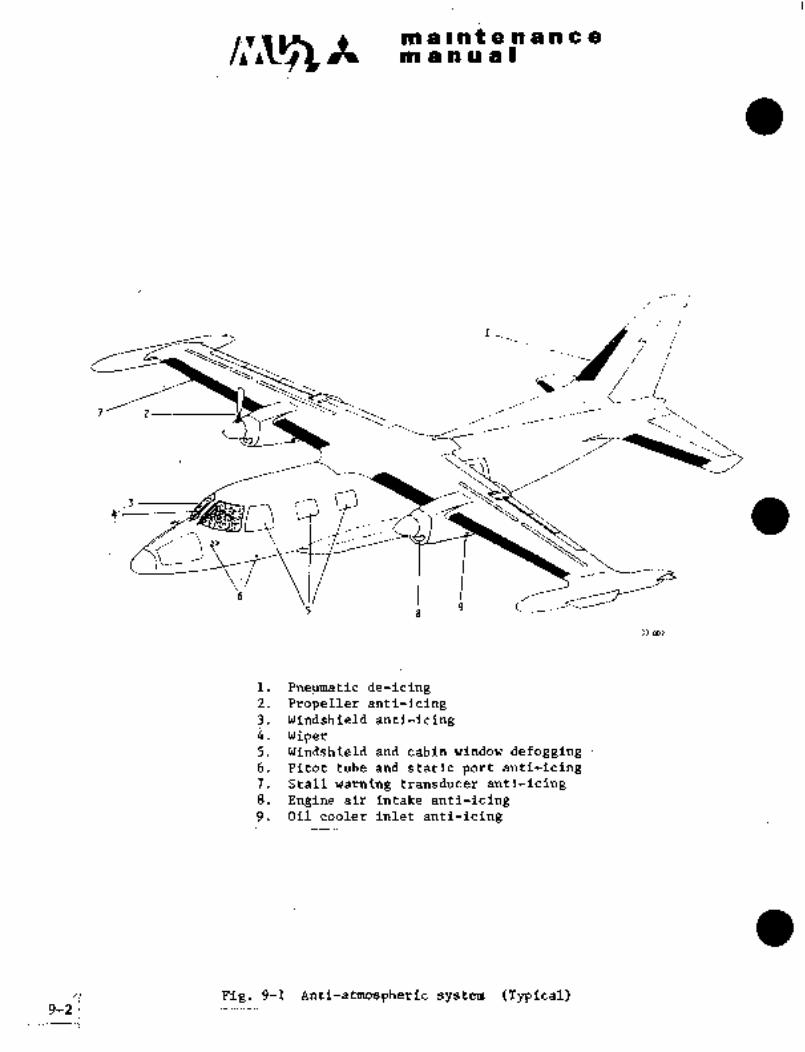
c~siii~ is i ia t. e~.ii a ii c ~ejin ~i a ii i~ I
I~7’ 2 ___,
r~J)
ij’ 9
30 W7
1.~ Pneumatic de-icing2. Propeller anti-icing3. Windshield anti-icingi.´• Wiper5. .Windshield ´•and cabin window defogging6. ´•Pitot tube and static port anti-icing7. Stall warning transducer anti-icing8. Engine air~ Intake anti-icing9. Oil cool~y inlet ~anti-icing
/i Pig. 9-1 Anti-atmospheric system (Typical)9-21

c~h atP a n a~ I
i 1 i 8 8
s\, i \1 i. Regulator relief valve
2. Manifold
3. Distributor valve
4. Ejector5. Timer
6. De-Icer switch
7. Pressure switch
I,h
8. Indicator light9. De-Icer boots
I2..~_ "Ii
80 001 8 ’8
Fig. 9-2 Surface de-icer equipment and syste’m
9-3

G~iS A sao a i i ´•a e n a R C ~iDin a P1U 1 I
2~2;i i4Ej~i;
ii) Remove LH ei~ctrical compartinent door (F,STA 8~15).
(2) Ijisconnect tube at the upstreain side of the pressure regulatorand relief ialve.
(3) Disconnect manifold from the downstream side of the valve.
(4) Remove valve attaching screws (3 ea.) and remove the valve.
(5) Remove reducer from the upstream and downstream ports; cap the ports.
(6~ Install in reverse sequence of removal, installing safety wii-e to
the attaching screws, and apply alignment mark to the coupling nuts.
2.3 MANIFOLD
The manifold divides the regulated air pressure for the boot de-icingsystem, fluid anti-icing system (if installed) and also to the entrance
door seal and pressure lock. The manifold is installed at the down-
stream side of the pressure regulator and relief valve.
2.3.1 REMOVAL AND INSTALLATION
(1) Remove LH electrical compartment door (F.STA 8615).
(2) Disconnect coupling nut from the upstream side of the manifold.
(3) Disconnect coupling nuts (3 ea.) from the downstream-side of
the manifold.
(4) Loosen and/or remove the hose clamp from the downstream side
of the manifold, upstream side of the ejector.
(5) Remove the manifold.
(6) Install in reverse sequence of -removal. After tightening nuts
and hose clamp to proper torque value, apply alignment mark.
9-4

~allnt e:n nce
I F:: i
i:a
Fig. 9-3 Pressure regulator and Fig. 9-4 Distributor valve
relief valve
Fig. 9-5 Ejector Pig. 9-6 Timer
:DORIGINAL
P
..!i
i´•2´•~ "r;.:´•
Fig. 9-7 PressMye switc:ll
9-5

c~sA n’i d~nf e:nan%;8manual
2.4 V~VE (Fig’i 9-4)
The distributor Salve iS cbnnected to the manifold o~ the upstreamside and to each boot on the downstream side. The valve incorporatesa solenoid to operate the valve’s three functions: boot inflation,boot deflation and a valve for the ejector to maintain a negative air
pressure in the boots. These functions are controlled by signals from
the timer.
2.4.1 REMOVAL AND INSTALLATION
(1) Remove LH electrical compartment access door (F.STA 8615).
(2) Disconnect wiring connector from the distributor valve.
(3) Disconnect tubing joints (4 ea.).
(4) Remove safety wire and 2 bolts installing the valve.
(5) Remove the valve and cap each port.
(6) Install in reverse sequence of removal. After tightening, attach-
ing bolts, install safety´•wire. After tightening hose clamps
apply alignment marks to each.
2.5 EJECTOR (Fig. 9-5)
The ejector is connect’ed to thenegative pressure (suction) port of
the distributor v~lve and to the manifold. The air pressure from the
manifold causes a negative pressure (suction) on the distributor valve,thus causing the boots to remaindeflated with the system OFF and aids
in deflation of the boots with the system ON.
2.5.1 REMOVAL AND INSTALLATION
(1) Remove the LH electrical compartment access door (F.STA 8615).
(2) Loosen and/or remove hose clamps (2 ea.) from the upstream side
(manifold and distributor valve) of the ejector.
(3) Remove nut, screw and clamp installing the ejector to the airframe.
(4) Remove the ej’ector.
(5) Install in reverse sequence of removal. Apply alignment mark
to hose clamps after tightening to proper torque value.
9-6

maintenancemanual
a1.6 TnaR (Fig. 9-6)
The timer sends a signal to actuate the distributor valveperrodicalllyso that the boot inflation and deflation cycle is completed. Duringautomatic operation, the timer sends a signal of 6 seconds ON and 174
seconds OFF, for a complete cycle (3 minutes). When the WING DE-ICE
switch is placed to OFF, approximately 2 seconds is required for the
timer to return to the starting position.
2.6.1 REMOVAL AND INSTALLATION
(1) Remove LH electrical compartment access door (F.STA 8615).
(2) Disconnect wiring connector.
(3) Remove attaching screws (4 ea.).
(4) Remove timer.
(5) Install in reverse sequence of removal.
2.7 PRESSURE SWITCH (Fig. 9-7)
The pressure switch is located in the pressure line between the distri-
butor valve and the wing boots. The switch is closed whenair pressure
increases to 10 f 2 psi (0.7 f 0.1 kg/cm2), illuminating an indicator
light in the overhead console. The indicatorlight is illuminated when
the surface de-icer system is in operationand the system is functioningnormally.
2.7.1 REMOVAL AND INSTALLATION
(1) Remove LH electrical compartment access door (F.STA 8615).
(2) Disconnect wiring from switch and identify.
(3) Remove switch from tubing.
(4) Install inreverse sequence of removal, noting the following:(a) Tighten to proper torque and apply alignment mark.
(b) Remove wiring identification, connect to switch and
install wire shielding as required.
2.8 RUBBER BOOTS
The de-icer boots are long thin plates made of rubber and are inflatedand deflated by means of compressed air to break away the ice mechani-cally. Service life depends on handling and maintenance practices toa great extent.
9-7

maintenancemanual
2’. 8.1 MAINTENANCE
(1) General
(a) Direct contact of ladders and worktables to leading edge boots
should not be made during airplane maintenance, etc. Apply pads of
cushion materials, etc, when contact with boots is unavoidable.
(b) Do not drag hoses over boots when servicing fuel or oil to airplane.Use protective pad in such cases.
(c) Do not step on boots when doing airplane maintenance, etc. Do not
put tools and equipment on-boots.
(2) Cleaning of boots
After flights, checks for oil, fuel and other harmful objects to
boots. Give special attention to horizontal stabilizer boots,because fuel and oil coming out of engine tend to adhere to them.
These materials should be removed as soon as possible.
(a) Clean de-icer boots with hot neutral detergent or hot water of no
higher than 180"F (82"C).(b) During cold seasons, clean boots at the inside of warm hanger if
possible. Preheat neutral detergent or water if cleaned at the
outdoors.
(c) If freezing may occur, warm with portable heater being careful not
to heat boots surface to 180"F or over.
If it is inevitable to use petroleum type’solvents in cleaning,wipe lightly with clean cloth moistened with the solvent, and then
quickly wipe dry with clean dry cloth before the solvent penetratesinto rubber. Because these petroleum type solvents give adverseeffects to rubber, they must be used sparingly.
(3) Surface coating (Application of ICEX)
(a) ICEX is a silicone based material specially compounded to reduceadhesive force between ice and rubber surface, harmless to rubber,and gives protection against ozone.
(b) When ICEX is applied, smooth glossy film is formed on the surface,and the boot surface with tiny microscopic irregularity becomes
flat. A chance of icing is reduced, and ice is quickly and
completely removed when boots are operated.(c) Give attention to the fact ICEX is not the greatest in de-icing
ability. The effects of application of ICEX is not in preventionof icing or removal of ice, but in prevention of strong adherence
of ice to make removal easier.
(d) Boots tend to be worn away by dust in air during flight. It is
recommended to reapply ICEX in every 150 hours of flight.(e) ICEX can be purchased from the following maker.
Nomenclature Maker ’s Name Address
ICEX YOKOHAMA RUBBER CO. 5-chome,Shinbashi, Minato-ku,Tokyo-to
9-8 3-31-90

c~ ~t~n a i a t a a a a ce
manual
(4) Environmental conditions
Because de-icer boot is a rubber product it ages when placedoutdoors for a long time. This phenomenon is´• expedited in very hot
or high ozone density areas. Therefore, it should be avoided to
place airplanes equipped with boots in the following areas for a
long time as much as possible.
(a) Near motors or other machines which generate ozone.
(b) High temperature areas over 1600F (70"C).(c) Areas with sunshine, harmful vapors, or unreasonably dense dust.
2.9 OPERATIONAL CHECK
Operational check of the surface de-icing system on the ground may be
accomplished as follows:
Required equipment:
Air supply source capable of 30 to 50 psi (2.1 to 3.5 kg/cm’) with
a regulator and gauge.
(1) Remove LH electrical compartment access door (F.STA 8615).
(2) Locate and remove plug cap from the ground test port.
(3)Connect ground air supply to the test port and apply air pressure
gradually until 30 psi (2.1 kg/cm") is attained.
(4) Connect APU and turn the Battery Key switch to ON.
(5) Check for WING DE-ICE circuit breaker "closed" condition and pressthe WING DE-ICE indicator light for illumination check.
(6) Place the WING DE-ICE switch in the overhead console to the ON
position(a) Check for uniform inflation and deflation of each boot; approximate
inflation height should be 0.25 in. (6 mm).(b) Check for the indicator light illumination during the inflation and
going out during deflation.
(c) The inflation and deflation time shall be within the acceptablearea in Charts 9-1 and 9-2.
3-31-90 9-8-1/9-8-2 1

c~h CtP -Int 451~ a; nce´•iroo; ai ii~ u a I
9.~:i i´•i;i i.: iIt´•’´• Ii
i i iB.S
ji li:ill1’1
BtO
7,5~"’: :i-/- ~i´•:;::t
7;0 i7-:-r´•---´•
i
[r(NITIOH -!i6.5 i ´•´•´•´•i
:1.1 i.:: .i.i.TIME 6.0
i
(SEtORDSi ii
5.5:i....
´•;1´• ´•´•i;;i_l~i;:l:::::s,a ii~l_´•i ir!: ;il iii.i.il4.iii:-~-LiCI.
i
:.I~j i I 1 i i i i i I !::i.i !I i
4,0I- ii
ELIEIPLE:!IHEI~ TEFIPERL~URE 240C(ljdF)i :::i
-i i.i.t iti:i 1111IniL~lon M(N 5111 8E~MIDSMax6;6 sacoiiIis 3,0
1’1
-lo -5 u 5 to 15 a 25 30 35 40 ’15 50´•55 60 OC
I I I I I I 1 I I
20 30 40 M 60 70 80 90 100 110 120 130 140 OF
Chart 9rl De-Ice boot inflation time TIMER AMBIEIT- TEMPERATURE91 oil
280:´•~i´•´•: i i i I
.:_i270i ~Knw
260’i"’
250 HI:i
i i i i´•i i240
’i
230 i.:i:i
!-i.ii220
i
’’i r:!i i´•! I´•i
,s
210t
200ir.l
I!190
aEeE´•~vEo sv tYCLE i j I I ITIIQ 180~
:1 II;: I i:´•::(SEtDHDS)
170:L- i i.: i i I;:I
;;_160 1-11
1M~(jl:l( ~i-jj:i-i’- iI.iiiii
j:~il ,i:140
:i.i ´•´•i
130
i:i::li:i:; i:iiBI- ii iI i I I I120
‘"D ei:´•i-~ ii il.iii: I.;i-ii ii ii:-:;1: i ilj::"iiiij i
100
I~Lni;
Fi4"’’so
i
ExnnpLr TlnER TEP1PERATURE. ?qOC (750F) Iiii:: ::::t_:.r:70
:~;.´•´•iCICLE 1INE MIN 56.5SECONbSMnd ~[1!1 ;ccoNo:- ilt I-I I;i ~:::II;:; i i i;-l-i´•; i; i i i i il´•i I I-I i ;:I ii:!
:-60i -10´•-5 0 5 10 15 20 25 M´•35 40 45 50 55 60 OC
I J~´•I I I 1 I _I _I I
20 30 40 50. 60 70 80 -90 100 110 120. 130 140 OF
Cka~t9-2 De-Ice boot cycle time. TEMPERATURE
st 012
9-9

in a in ii~ a I
(7)late~ tb ens~re tbetim~r has reset to the iafiafion Tetarf)
PF and-ON again 3 b 1 QecbndsPlace WING DE-ICE´• to
or the cyclei
(8) Clds~ the gi~ supply and release the air ptessure in
the surface de-ice systemi
(9) Place WING DE-ICE switch and turn the Battery Key switch to the
OFF positiori.
(10) Remove the air supply source from the test port and install the
plug cap to the test port.
(11) Install the LH electrical compartment access door (F.STA 8615).
(12) When the operational check of the system is performed on~the
ground during engine ground run, steps (1) through (4) and (8)
through (11) are not required.
2.10 TROUBLE SHOOTING SURFACE DE-ICING SYSTEM
Trouble Probable cause Remedy
Boots do a. Distributor valve does i. Make sure that light illumi
not inflate not operate. nates when indicator lightis pushed. (If not,
electrical system is faulty.)ii. Confirm timer operation.
(Replace if necessary.)iii. Inspect va~lve.’ (Replace
if found faulty.)
b. Boot line is broken Repair. ,Iand air is leaking.
c. There is leakage or I´• Correct leakage or remove
obstructed tubing foreign material.
between distributor
valve. ´•and hoots.
Boots inflate a. Faulty wiring. I Check.
but indicatorb. Faulty indicator light. Replace light.
light does not
illuminate c. ’Faulty pressure switch. Replace switch.
d. Air pressure is Check air lines fo~ leakage.insufficient.
e. ‘Faultydistributor. ~heck air lines for leakage.
f. Faulty regulator and Replace regulator and relief
relief valve. I valve.
Boots inflate la. Faulty distributor valve. Replace valve.
but do not deflateb. Faulty´•timer. I Replace timer.
9-10
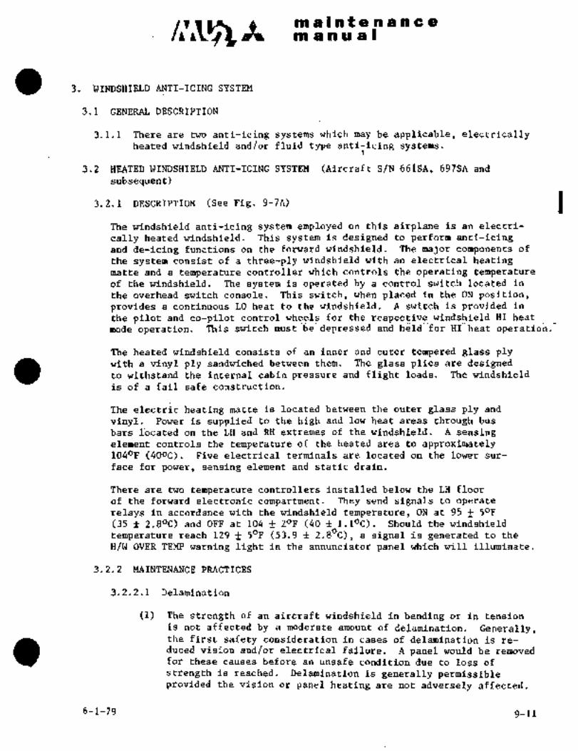
C~jS ra a In~ a n;a a a a
as a. a a a I
WINDSHIELD ANTI-ICING SYSTEM
GENERAL DESCRIPTION
3.1.1 There are two anti-icing systems which maybe applicable, electricallyheated windshield and/or fluid type anti-icing systems.
~.z BEATED WINDSHIF~LD ANTI-ICING SYSTEM (Aii-craft S/N 661~SA, 697SA and
subsequent)
3.2.1 DESCRIPTION (See Fig. 9-7A) IThe windshield anti-icing system employed on this airplane is an electri-
cal´•ly heated windshield. This system is designed to perform anti-icingand de-icing functions on the forward windshield. The major components of
the ´•system’consist of a three-ply windshield with an electrical heatingmatte and a temperature controller which controls the operating temperatureof the windshield. The system is operated by a control switch located in
the overhead switch.console. This switch, when placed in the ON position,provides a continuous LO heat to the windshield. A switch is provided in
the pilot and co-pilot control wheels for the respective windshield HI heat
mode’operation.~ Thisswitch.mustbe depressed and held for HI heat operation.
The heated windshield consists of an inner and outer´•tempered glass plywith a: vinyl ply sandwiched between them. The glass plies are designedto withstand the internal cabin pressure and flight loads. The windshield
is of a fail safe construction.
The electric heating matte is located between the outer glass ply and
vinyl. Power is supplied to the high and low heat areas through bus
bars Ibcated on the LH and RH extremes of the windshield. A sensingelement controls the temperature of the heated area to´•approximately1040F (40oC). Five electrical terminals are located on the lowersur-
face for power, sensing element and static drain.
There are two temperature controllers installed below the LH floor
of the forward electronic compartment. They send signals to operate
relays in accordance with the windshield temperature, ON at 95 f 50F
(35 f 2.80C) and OFF at104 f 20F (40 l.loC). Should the windshield
temperature reach 129 f 50Fi (53.9 f 2.80C), a signal is generated to the
H/W OVER TEMP warning light’ in the annunciator panel which will illuminate.
3.2.2 MAINTENANCE PRACTICES
3.2.2.1 Delamination
(1) ´•The strength of an aircraft windshield in bending or in tension
is not affected by a moderate amount of delamination.´• Generally,the first safety consideration in cases of delamination is re-
ducedvision and/or electrical failure. A panel would be removedfor these causes before an unsafe condition due-to loss of
strength is reached. Delamination is generally permissibleprovided the vision or panel heating are not adversely affected.
6-1-79 9-11
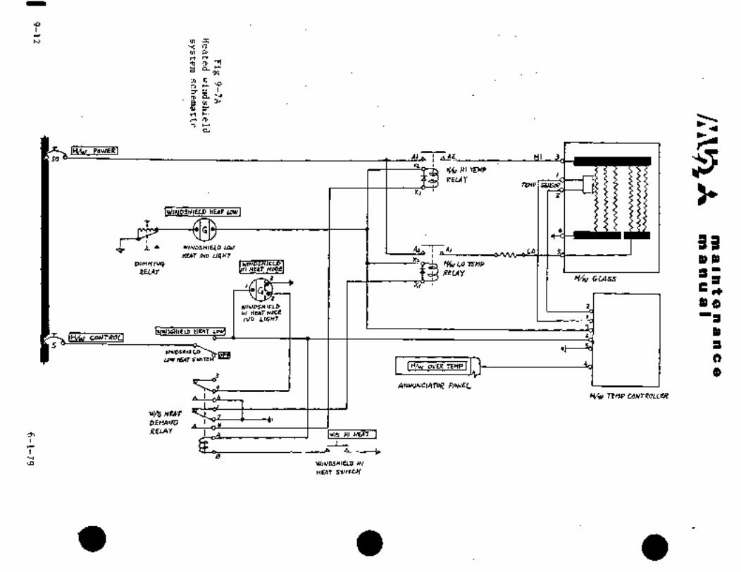
\O
r
m 3:Y (D
rn Eurt~t
oo
m
n r´•’o
P&YBm~
rrr r´•
.n,o~-
a
IH~v PawEK1Cr=r56 dl AZ WI 3
nHSv HI TEnP
RELAYTEnP1SMhe
XI
hVINDSHIELD HUIT MVJIELD HUIT MV
r
uxu I I I LO33
HEaT n~D U6HrX2 3)3)
RELQYY~u Lo TEMP16REtAy ~UIT
3 ~t/w C;L4sS
3+
WI~DSHIELD I i I I 1 2 3)(3WIHUITnoDE I I 1 I I .1 I- IIU~ LIGHT
PDIELD nUTILkl caurnoU 6
WIUDIHIELD
LDYTHEAT
IH/W OVER TE)IPIb)
ANARINaAroip PAEJEt’
Y/w rrnp CONTROLLER
w/s HEAT
DErVIND
REm* Iwn HI WFAT IA
r
HRUDSHIELD WI\o
nEAr SYIITCC(

~i´•-
no Iln -g:;n a so c a
’iif~ Li ns so rB
c~ b penefratfon ´•iato- ther I ’.-1
’iriteir A Islrl5;eresu~t rrom the. absence or’iacir of mai~tenaace:Bi;´• the’tJe~thei:
arouna the of ’A.II.:.
lo~ in~-iky in th~: ~SGiriiprg3ess:iani and, shulh tie replBcedA area is an Irreguiar dr
botmairji; TtjlE;’separ~tioii ~rii3iicaQes t~at the vihjilbi~d glass are not iirii’fdrmi Such r6na´•iti´•on ~an the
viiiyl to pull chips from the inner which couldlead to failure of the glass ply. In case of such delamilia-tioniaperiodic inspectioni~s reconrmended to determine if
the dainagP is progr~ssive, orif chipping of the innerglasssurface ´•is present. Replace the windshield if either condi-
tion exists.
(3) Generally, a delamination is characterized:by B smdoth-~edgebbundary ahd is ´•ci~ear (not.cloudy).; therefore ~nod-progressionexists as the st~resses Cau~ing such a del.aminatidn are relieved
when the delamin8fibn occu~s..
5.2.2.2 Anti-Static Tabs
Windshields that havea coating on thesurface of the’
outboard ply of the glas’s also have an anti-static’ tab, groundcontact. There are generally two types of tabs.. One is a
metal finger´•that grounds to the airframeiand the other is a
fiber-glass shielded tab fhat is connected to the electrical
grounding system of the’ aircraft. All fiber-glass shieldedtabs should~ be painted with a urethane base paint. to protectagainst windand rain´•erosion and ultra-violet light exposure.
3.2.2.3 Removal /Installation
A. Removal -Windshield
(1)- Disconnect wires fromterminalblock and-identify.
(2) Remove windshield in accordancewith Chapter III, para. 5.2.
(3) Install in-reverse sequence of removal.
B. Thetemperature controllermaybe removed and.installed as
follows
(1)~ Remove the forwardlHaccess panel below the electronic
compartment floor,
(2) Disconnect the wires and identify.
(3)’Remove the attaching screws and’the controller.
(4) ~‘Tnstall iri reverse´• sequence of removal.
9-13´•

C~Sa a a a a I
3.’2;2.4 Operationgl Chck
The’ windshield anti~fcSng system may bp$lated~ i~heri
the aircraft powef system is in operation. The syst’erq is op8ra-´•tidn~l ~y placiizg theoverhead don~ole to
ON. Normally, when the control switchis ON, the LO HEAT portionof the glass is heated. In severe icing conditions the HI HEAT
portion of the glass is heated by operation of the HI HEAT switch
in the control wheels. During HI HEAT operation, the LO HEAT
portion becomes inoperative.
The inspection procedures are as follows:
(1) Make sure that both control switches in the overhead console
are in the OFF position.
(2) Connect DC power.
(3) Place the WINDSHIELD HEAT-LH switch in the overhead console
to ON and make sure that the indicator light ON illuminates
and the LH windshield becomes warm gradually.
(4) Place the WINDSHIELD HEAT-RH switch in the overhead console
to ON and make sure that the indicator light ON illuminates
and the RH windshield becomes warm gradually.
(5) Insure the indication lights repeat the ON and OFF cdndi-tions with the switches ON.
(6) With the WINDSHIELD HEAT-LH switch ON,´• depress the W/S HI
HEATswitch in the pilot’s control wheel. Make sure the
LH W/S HI HEAT MOD~ ON indicator light illuminates and the
HI HEAT operation of the LH windshield becomes warm gradually.
(7) With the WINDSHIELD HEAT-RH switch ON, depress the W/S HI HEAT
switch in the co-pilot’s control wheel. Make sure the´• RH W/SHI HEAT MODE ON indicator light illuminates´•and the HI HEAT
portion of the RH windshield becomes warm gradually.
(8) Insure that the W/S HI HEAT MODE ON indicator. light repeatsON and OFF conditions with the W/S HI HEAT switch in the
depressed condition.
N8T~
The operational check should be per-formed ata temperature less than 100oF
(37.80C). When the windshield temper8-ture is more than 1000F (37.80C) the relayis OFF at all times and operationalcheck can not be performed.
9-14
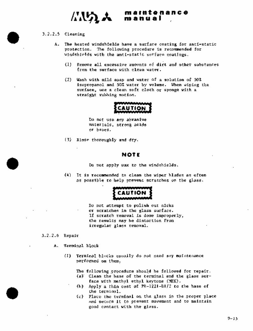
c~n ai a in a a Iiii ii i ii t a a a a c a
3.2.2.5 Cleaning
A. The heated windshields have a sulface coating for anti-static
protectibn.: The following procedure’is recommended for
windshields with the anti-static surface coatings.
(1) Remove all excessive-amounts of dirt and other substances
from the surface with clean water.
(2) Wash with mild soap and water of a solution of 50%
isopropanol and 50% water by volume. When wiping the
surface, use a clean;soft cloth or spong~ with a
straight rubbing’motion.
CAUTION
Do not use any abrasive
materials, strong acids
or bases.
(3) Rinse thoroughly and dry.
NOTE
Do not apply wax to the windshields.
(4) It is clean the wiper blades as often
as possible to help prevent scratches on the glass.
CAUTION
Do not attempt to polish out nicks
or scratches in the glass surface.
If scrat’chremoval isdone improperly,theresults may be distortionfrom
irregular glass removal.
3.2.2.6 Repair
A. Terminal.:Block
(1) Terminal block’s us;ially ~do. not need any maintenance
performed on them.
The following ~procedure should he: followed for:repair.(a)’ Clean:the,bas~e’of the terminal’and the glass’sur-
face with:methyl ethyl’ keytone (MEK).(b) Apply a thin coat ´•of PR-12211B1/2 to the base of
the terminal.
(c) [Place the terminal’ on the glass in the.proper placeand secure it to prevent movement and to maintain
good contact with the glass.
Y-15

i’in a i at B a a a a a
~m a ii a a I
NOt E
U~e masking tape to hold block in place.
(d) Remove excess PR-1221-B1/2 from around edges of
terminal block.
NOT~
Allow the PR-1221-B1/2 sealant
to cure for 24 hours before
removing the tape.
B. Anti-Static Tabs
(1) Mask all exposed glass surfaces.
(2) Remove ~ab from over bonding position.(a) For metal tab, remove the screw that fastens it
to~the airframe and lay the tab to one side.
(b) For fiber-glass tab, the tab cannot be completelyremoved since it is tied into the unit by a metal
braid.
NOT IE
Be very careful not to tear
the braid connecting the tab
to thegrounding system; justplace the braid away from
the bonding area.
(3) Bonding Surface Preparation(a) Silicone under tab finger.
(1) Carefully and thoroughly remove and clean all
the conductive silicone that remains on the glass.
NOtL
Be extremely careful not to
scratch t~e glass surface.
(b) Epoxy based under tab finger.(1) Carefully roughen the surface of -the electri-
cally conductive epoxy which remains on the
glass surface.
(2) Clean t~e´• tab and~rough the surface.
(4) Apply conductive silicone (Technik RTV silicone, P/N72-00002) to the tab and also to the glass surface.
(5) Apply the tab to the windshield(s) and if the tab is of
the metal finger type, install the screws.
(6) Remove windshield maskings.
9-16

m am tm a ill u a i´•
a s., nuID ANTI-ICING SYSTEM (Aircraft SIN 652SA a~d Aircraft equippedwith system)
3.3.1 DESCRIPTION
il~ie flu~d-’anti-icing system consists of a pressure control valve which
controls air pressure from the engine bleed air system which forces
the fluid from the tank to the spray nozzles. The anti-icing fluid is
a mixture of 60% ethylene glycol (MIL-A-8243, Amend i, MIL-E-9500,MIL-H-5559 or 0-A-00548) and 40%water The fluid flow rate is 1.7
U.S. pints (0.804 liters)/minute to both the left and right windshieldsurfaces. The tank capacity is approximately 2.5 U.S. gallons(9.46liters).
When the windshield anti-icer switch is placed-ONin icing cond~itions,the solenoid valve inthe pressure control valve opens, allowing enginecompressor.bleed air to flow. The air, controlled~ to specified pressure,
pressurizes the.fluid tank. Pressurized anti-icer fluidis sprayedfrom the nozzle to windshield surface and then dispersed by free air
stream flow. The wiper.is used as required. The fluid tank’ is located
on the fuselage on the right side of the nose landing gear.bay. ´•The
antiiicer fluid filler port is located in the electronic compartmentabove the tank (Pigure 9-8).
NOTE
ai. Do not usethe.anti-icer fluids
(such as isopropyl alcohol,.ethyl´•alcohol, etc.) other than
ethylene glycol.
ii. ´•Flush thewindshield with clean
water´•after using anti-icer fluid.
3.3.2 .PRESSURE CONTROL VALVEI
The pressure contro~valve, installe8:on the RH forwardsectionof
the pressure bulkhead in the electronic compartment, is installed
between pressurizing air source and anti-icer fluid tank. This valve
notonly controls pressure of engine compressor bleedair to 8 psi(0.6 kg/cm2), but also actuates the pressure relief mechanism when
pressureonthe downstreamside of the valve reaches 12 psi (0.8kg/cm2),. .preventing pressure’~from´• rising above the limit.
When the anti-icersystem is~not inuse ~i.e., solenoid valve in
pressure dontrol valve is ciosed’and pressurized air is not flow-
ing), the discharge port:opens to preventingdiffer.ential pressure. bet~nieen inside and outside´•of the tank. A
check valve is installed’in--the ’pressure ~control: valve to avoid
reverse flow of anti-icer fluid.
9-17

c~s It m alnt a a a a a a
m a a a at
"r
1
4
i i"!"
Control- assembly
ORIGINALi. Nozzle 6
2. Engine com- As Received Bypresser bleed air AT P
3. Control assembly
4. Filler cap
5. Clamp Windshield anti-icer equipment6. Anti-icer fluid tank Fig. 9-8
3.3.2.1 REMOVAL AND INSTALLATION
(1) Remove RH electronic compartment access door.
(2) Remove access panel on RH STA. 1080.
(3) Disconnect wiring connectors.
(4) Disconnect tubing on upstream and downstream sides of valve.
(5) Remove bolts and washers attaching valve, and remove the valve.
(6) Remove union (1 ea.) and elbow (1 ea.) from valve and plugeach port.
(7) Install in reverse sequence of removal.
9-18
;.I
a I la a8 nacl ;e e
a a a
5.3:3 ANT~;ICER. Fi~iTaIj TANK
The airti-i´•C~r fluiii eank is installed in the fuselage, RH section of
nose landing gear cdn~ected with pressure line to
Suppijl air from cbntroi assembly to tank, and: anti-icer fluid line to
lead fluid to nozzlesr
A float type check valve is Provided at the pressure line connecting
port and prevents reverse flow of anti-icer fluid in pressure line and
leakage to relief port of’control assembly while system is not in
operation.
3.3.3.1 RE~OVAL AM) INSTALLATION
(1) Remove RH electronic compartment access door.
(2) Open access dbor at F.STA 350-930.
(3) Remove pressure line and anti-icer fluid line from tank.
(4) Remove tank attaching bolts and remove tank.
(5) Plug‘ each port.
(6) Remove clamps from tank.
(7) Install in reverse sequence of removal.
3.3.4´• TIMER
The timer is installed on the overhead console and is operated by
placing the windshield anti-ice switch to "WINDSHIELD ANTI-ICE!’. The
timer actuates the control assembly periodically by sending electric
current. "ON" time is about 4 seconds (constant) and "OFF" time can
be set to optional value between 0.5 thru 8seconds by means of
anti-ice cycle Selector.
3.3.5 ANTI-ICE dYCLE~SELECTOR
The anti-ice cycle selector changes operating cycleof the timer. "OFF"
time of the rimer-is about 0.5 seconds in "FAST"-position and about 8
seconds in "SLO~" position. Setting,should be ~made according-to icingcondition. r
1
9;19

~ia s´•n t a rb~an c a
m a tP’U a I
3.3.6 OPERATIONAL CHECK (Fig. 9-9)
Confirm that the WINDSHIELD switch in the overhead console is
in the OFF position and circuit breaker AIR COND is open.
(2) Connect DC power (28 VDC battery or external power).
(3) Pdur 0.5 to 0.8 gal. (2 to 3 L) of water´•into the fluid tank.
(4) Remove the LHelectrical compartment access door (F.STA 8615).
(5) Locate and remove cap plug´• from ground test: port; connect ex-
ternal air supply source (capacity: 30 to 50 psi (2.1 to 3.5
kg/cm2) with regulator and gauge).
(6) Grad~ally pressurize and stabilize the system to 30 psi (2.1kg/cm2).
(7) Turn Battery Key switch to ON, close circuit breaker, place the
switch to the AUTO position and confirm the fluid is sprayedfrom the nozzles to the windshield surfaces to the specifiedarea as shown in Fig. 9-9.
(8) Confirm cycle operation of spraying for 4 seconds and stoppedfor 0.5 seconds in the FASTposition, and spraying for 4 seconds
and stopped for 8 seconds in the SLOW position.
ON ~--7 ~---´•1B 0.5 seconds 1´•gs´•Ate-~te;LtB A 4 seconds
I I ’I I I A 4 secondsQFF--- ´•--J ´•L--J L--J
B 8 seconds
(9) Place switch to OFF position and confirm spraying is stopped.
(10) Place the switch to MANUAL position and confirm a continuous
spray from the nozzles; place´•to OFF when the fluid tank is
empty
(11) Turn the Battery Key switch to OFF.
(12) Close air supply source, release the air pressure from the system
and disconnect the air supply source from the ground test port.
Install the cap plug.
(13) Install the LH: electrical compartment access door.
(14) When the operational check df this sytem is-performed on the
groundduring engine ground run, steps (2), (4) through (6)
and (11) through (13) are not required.
.9-20

no a it at a a a a a aon a 91 a a
Point where anti-icer fluid 3
is sprayed on ´•the windshield
8a---d~-:----------o----,
c E-___1
-c´•o
A 7-rA 8.7 in.
(220 mm)All dimensions are measured on
the glass surface.
\1i. Air supply line
2.´• Control assem6ly3. Anti-ice control switch
4. Timer a
5. Cycle selector:30 005
6. Anti-icer ´•Eluid tank
7. Filler cap
8. Spray nozzle
Fig. 9-9 Windshield anti-icer systera
3.3.7 TROUBLE SHOQTING WINDSHIELD A.NTI-ICING SYSTEM
Trouble Probable cause Remedy
Anti-icer fluid a. Anti-icer fluid tank is empty. Fill tank with anti-icer.
ddes not sprayb. Control assembly does not i. Check electrical circuit.
operate. ii. Replace valve if it is
defective
c. There is leak between Repair component which
control assembly and leaks.
nozzles.
e. Nozzle is blocked. Tightencap.
d. Tank filler cap is not Remove foreign material
closed tightly. in nozzle hole with wire.
f. Timer does not i. Check~electrical
work. ci rcuit.
ii. Replace timer if it is
defective
Anti-icer fluid spray a. Control assembly Replace valve.
can not be stopped faulty.b. Timer faulty. Replace.
Anti-icer fluid spraying Timer faulty. Replace.cycle varies and anti-
ice cycle selector does
not change cycle
9-21
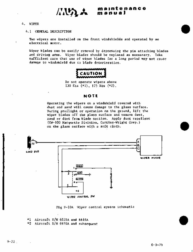
m a Int a a a a a a
m a a a a I
4. WIPER
4.1 GENERAL DESCRIPTION
Two wipers are installed on the front windshields and operated by an
electrical motor.
Wiper blades can be easily removed by depressing the pin attaching blades
and driving arms. Wiper blades should be replaced as necessary. Take
suSficient caLe that use of wiper blades for a long period m~y not cause
da~nage to windshield due to blade deterioration.
CAU´•TION
Do notoperate wipers above
130 Kts~(*l), 175 Kts (*2).
NOTL
Operating the wipers on a windshield covered with
dust and sand will cause damage to the glass surface.
During preflight or operation on the ground, lift the
wiper blades off the glass surface and remove dust,sand or dirt from blade section. Apply dust repellent´•(CW-100 Marquette Division, Curtiss-Wrfght Corp.)on the glass surface with a soft cloth.
1.5
U3AD 8US
~VIPER MOfOE
ILPeSILI
z IPEEI)jD-------~te
s I
06
WIPER coUTRoL SW
Fig 9-10A´• Wiper control system schematic
*I Aircraft S/N 652SA and 66rSA*2 Aircraft S/N 697SA and subsequent
9-226-1-79
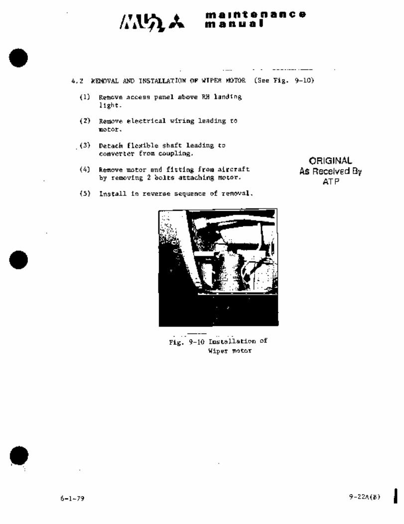
c~5m a a t a a a a a a
m a a an a I
4.2 REMOVAL AND INSTALLATION OF WIPER MOTOR (See Fig. 9-10)
(1) Remove access panel above RH landinglight.
(2) Remove electrical wiring leading to
motor
(3) Detach flexible shaft leading to
converter from coupling.ORIGINAL
(4) Remove motor andfitting from aircraft As Received Byby removing 2 bolts attaching motor.
AT P
(5) Install in reverse sequence of removal.
Fig. 9-10 Installatibn of
Wiper motor
6-1-79 9-22A(B)

´•~t m g i a t’e a a a’c airm a a iii a, i
4.3 REMOVAL: ~ND INSTALLATION.OF C~NVERTER (See Fig.´• g-il)
(1) Ijisconnec.t fleXible shaits´• from ea~h convertei: loeated air ~ipperbdc~ (F.STA 1275) of instrument ~anel;
(2) Remove triper blade and drive arin converter shaft;
(3) Remove honveltei. from ~iirtraft by removing bolts dttdching eachconve~ter.
(4) .Inst~il in reverse sequence of L~emoval.
O i::: ~P
I,e ft con\´•e rte r liight converte r
i. Motor
2.
3. Flexible- sh~ft
4. Wiper
L~k
I;Ip;a c3~.
,u
B
Ffg.9-ll Installation bfmotor andconverter- (1/2).(Typical’-S´•/N 652SA:’~and ~661SA) I~
9-23

maintenanCem a a a a i
A
n~s ~Gc3B~i B
/ir.
i: B
a ~´•?-s- d
1.M~tor’7
2. Converter i I3. %lexible shaft
4. Wiper B /i
bP’3/18
Fig. 9-11 ’Installation of motor and converter (2/2)(Typical’S/N 697SA and subsequent)
9-24
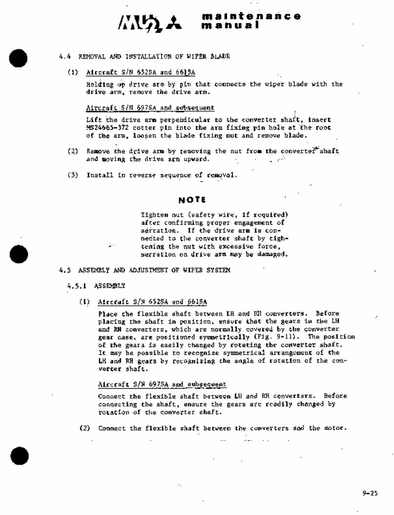
C~ It m a ~i at a A tir~i c a
liil a a a a I
4.4 REMOVAL AND OP WIPER BLADE
’652SA‘ and 66iSA
Hbldihg .drive armby pin that cbdaects the wipe~ biadB with the
drive arm, remove the drive arm.
Aircraft S/N 697SA arid.subsequent
Lift;:hedrive arm perpendicular to the converter shai’t, insert
MS24665-372 cotter pin into the ´•arm fixing pin hole a’t root
of the arm, loosen the blade fixing nut and remove blad~.
(2) Remove the drive arn; b)i removing the nut from the~ converee;~idbshaftand moving the drive arm upward.
(3) Install in reTierse sequence b´•f removal.
NOTL
Tighten nut (safety wire, if requiieed)after confirming proper eng~gement of
s~rratibn. If the drive arm is con-
nec’ted to the conveyter.shaft.by tigh-tening the nut with ekcessive force,serration on drive arm may be damaged.
4.5 ASSEMBLY AND ADJUSTMENTOF WIPER SYSTEM
4.5.1 ASSEMBLY
(1) ´•´•Aireraft S/N 652SA and 661SA
Place~the flexible shaftbetween LH and RH converters. Before
placingthe shaft in position, ensure that the gears inthe LH
and’RH converters, which are~normally coveredby theconverter
gear case, are positioned symmetrically (Fig. 9-11).. The positionof thegearsis easily changed by rotating theconverter shaft.
It may be possible to recognize symmetrical arrangement of the
LH and RH gears’by recognizing the angle.of rotation of´•the con-
verter shaft.
AircraftS/N 697SAand subsequent
Connect the flexible shaft between LH and RH converters. Before
connecting:.the shaft, ensure the gears ar~readily changed byrotation of the donverter´•shaft.
(2) Connect the flexible shaft between the converters and the motor.
’i
9-25

C~ It lip a i~n t.8’.n a a ~i:c~i
tit a ii a jEi
4.5.2 ADJUSTNT OF SYMME~RICAL MOTION OF LH AM) RH BLADES
(1) Aircraft S/N 697SA and subsequent
Li~t the blade off the glass surface and insert a 1/8 inch dia.
cotter pin into the side hole of the arm.
(2) Turn wiper switch ON. When LH wiper blade travels to innermost
position, turn switch to OFF. If RH blade is not symmetricalwith LI-i blade, adjust as follows:(a) Remove flexible shaft frbm LH converter.
(b) Turn wiper switch ON, actuate RH blade. When blade travels
to the innermost position, turn switchOFFr The position of
the RH blade must coincide with that of the LH blade, where
both blades cease to travel at the innermost position.(c) Connect flexible shaft. Turn wiper switch ON and ensure
symmetrical movementof LH and RH wiper blades.
(3) Aircraft S/N 652SA and 661SA
Position of converter gears can be set symmetrically by Para. (2)above. Adjustment to set.arm symmetry is made by removing and
turning adjusting sleeve (adjusting sleeve has 50 serrations
inside and 51 outside; minute’adjustment of 0.03 in. (0.8 mm) at
the arm tip is available). In this case, remove the bolt at the
converter shaft end and loosen~allen screw. Adjust and return
hardware to original configuration.
(4) Aircraft S/N 652SA and:661SA
Remove cotter pin and allow blade to return to position on the
glass surface.
4.5.3 ADJUSTMENT OF PARKING POSITION
Applicable to aircraft S/N 652SA and 661SA
(1) Adjust the parking limit switch in accordance with the followingprocedures.(a) Turn wiper switch ON; when the blade travels to its outer
position, place the switch to PARK.
NOTE
Wiper.shouldnotbe operatedon a dry windshield.
(b) Adjust: the-cam position. in the converter as shown below,such that the blade may travel from outer position to
inner position and r~turn to the parking position auto-
matically.
9-26
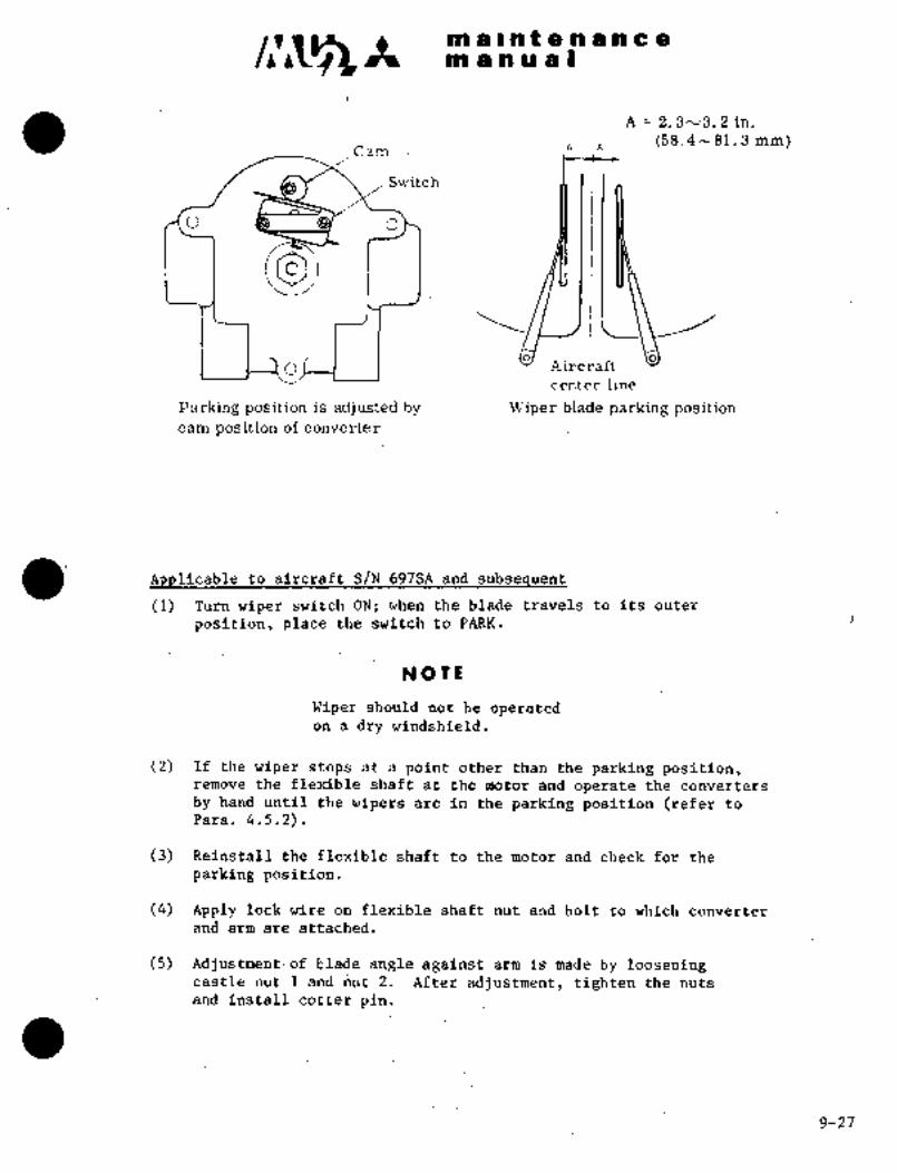
c~s m a .lnten a. nca
m a a a a I
´•A 2. 3´•v3. 2 in.
t\ n (58.4 hi 81~ 3 mm)Cam
Switch
O D o
o o
C) Aircraft
center line
Parking position is adjusted by Wiper blade parking positioncam position of converter:
´•~pplicable to aircraft S/N-697SA and subsequent
(1) Turn wipPr switch ON;when thebladetravels to its outer
position, place the.switch to´•PARK.
Na T´•~
Wiper should not.be operatedon a dry windshield.
(2) If thewiper stops at a pointother than t~ie.parking´• position,remove the flexible shaft at the motor and operate the. converters
by hand until the wipers are in the parking position (refer to
Para. 4.5.2).
(3) Reinstall the flexible shaft to the motor and check for the
parking position.
(4). Apply lock wire on flexible shaft nut and bolt to which converter
and armare attached.
(5) Adjustment: of blade angle against.arm iS made by looseningcastle nut After adjustment, tighten the nuts
and install cotter pin.
9-2i
m iii i h t 4e ti a a a ~bm a a a a i
I\iax. ’mlin
Windshield center
post
Wiper bladeN OT
tie nut 1
ut 2 ~Blade should not be on
Max. 35 mm retainer and/or retainer
I seal of center post.
4.5.4 ADJUSTMENT OF WIPER BLADE CONTACT PRESSURE
Check the wiper blade ´•contact pressure in accordance with the followingprocedures:
Set the wiper blades to the position shown in Fig. 9-12.
(2) Pull the blades~ perpendicular to the glass surface at the
position where the driving arms are most extended.
(3) Measure the tension force when the center of the blades comes
off the glass surface.
if the wiper blade contact pressure is not within the specific value,
adjust in accordance with the following procedures:
(1) ~1 Adjustment of blade contact pressure is made by adjustingthe length of the spacer.
*1 Aircraft S/N 652SA and 661SA
9-2,5

c~a rii a 1-iit n a ii a
tn a a ii i I
:6~7A~ 8.47f 0,4 in. (215 ’t, 10 mm) kl
a =´•8,86 f 0.4 in. (225 f 10 mm) *2
ii
Tensio
Specified ValueWiper
blade1.7 to 2.7 Ibs. (0.8to 1.2 kgs)’"l
hield’.~ 3.5 to 7.0 Ibs. (1.6 to 3.2 kgs) "2
glass surface
*1 Aircraft S/N 652SA and 661SA
*2 ~Aircraft S/N 697SA and subsequent
Fig. 9112 Blade,Contact Pressure
´•9-29

It´• tn ii Int e ’n;a a a amanual
NOTL
The converter shaft angle should be
adjusted such that it remains parallelwith the airplane axis. Do not lean
the shaft to the left or right.
Driving arm
attaching bolt
ConverterSpacer
attaching bolt
~2 Adjustment of blade contact pressure is made by turningadjusting screw of the drive arm with WX20509 wrench.
NOTE
To increase the contact pressure, turn
clockwise, and to decrease contact pres-
sure, turn counterclockwise.
(2) *2 After adjustment, operate for 30 seconds and ~echeck the
contact pressure.
Blade contact
pressur.e adjust~in~ screw
Arm positionadju stingsleeve´•
Ar´•m fixing
pin hole
Sleeve fixing Alien screw
~2 Aircraft S/N 697SA and subsequent
9-30
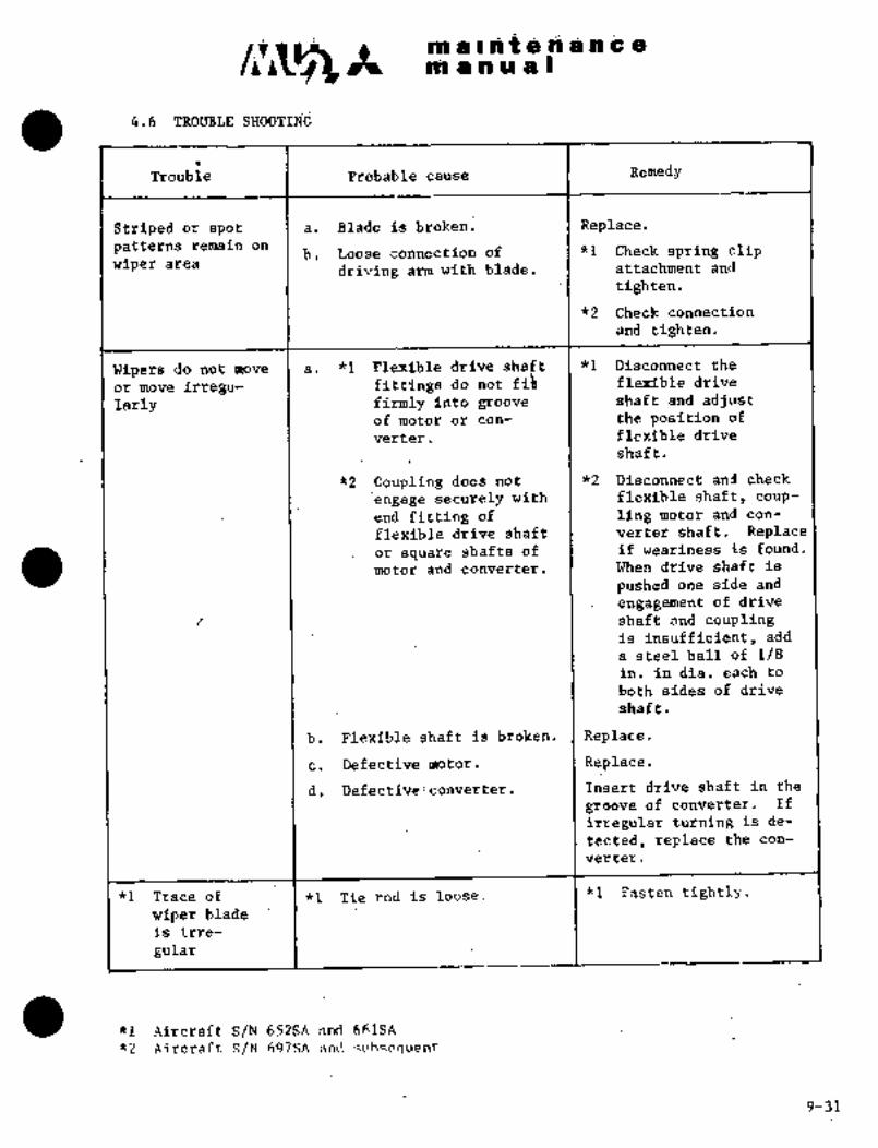
~iii iii i~ ~eiii a ii I
4.6 SHOOTIN~
Tr;oub ie I Probable cauSe I
Striped o~ spot :I a. Blade is broken. Replace.
patterns remain dnb~ Ldose cdnnecti6n of .1 *1 ChPck Bpring clip
wiper aiCadriving arm with blade. I attaChment and
ti~h ten.
~2 CheCk co~nection
and tighten.
Wipers do not move a; "1 shaft *1 Disconnect the
or move irregu- fittings do: not fih flexible drive
larry firmly into groove shaft and adjust6f motor or con- the position of
verter. I flexible drive
shft.
*2 Coupling’ does not 1 "2 Disconnect´• and check
engage Securely with I´• flexible shaft, coup-
end fitting of ling motor and con-
flexible drive shaft I verter shaft. Replace
or square shafts of I if weariness is found.
motorand converter. When drive shaft is
pushed one side and
engagement of drive
I I shaft and couplingis insufficient, add
a steel ball of 1/8in. in dia. each to
both sides of drive
shaft.
b. ´•Plexible :shaft:-isbrdken. I Replace.
c. Defective motor. i Replace.
d. Defective:converter Insert drive shaft in the
grooGe of converter. If
irregular turning is de-
tected, replace the con-
verter.
fl Trace of- Tie rod is: ~oose. "1 Fasten tightly.
wiper-blade
g,iarI
*1 Aircraft S-/N’´•652SA and ´•661SA: ;i.:..i:
*2´• Aircraft ´•S/N 697SA and~-,uhsequent:..
9-31

~ii a In ~lte ~i a a ac~´•t ni iP a iu a I
5. DEFOGGING SYSTEM
5.1 GENERAL DESCRIPTION
Windows consist of front windshields, side windshields and cabin windows.
Windshields and cabin windows are defogged by conditioned air from the
defogging air outlet in the lower section of windshield and cabin windows.
A thermostat switch is installed on the front windshield defogging air
outlet. When defogging air temperature reaches 200 -4 50F (93.3 f 2.80C)due to air conditioning system failure, the switch actuates and illuminates
DEFOG OVER TEMP warning light to indicate abnormal condition of defoggingair.
5.2 WINDSHIELD DEFOGGING
The windshield defogging system consists of air conditioning-defoggingselector valve incorporated in the forward conditioned air outlet,defogging air outlets, tubing and main outlet flow control valve
for defogging capacity augmentation in extremely cold weather.
5.2.1 DEFOGGING SELECTOR VALVE (See Fig. 9-13)
This selector valve is a butterfly type and can be set for COND to
supply conditioned air to cabin and DEFOG for windshield defogging.For windshield defogging, turn the knob in the outlet towards the
arrow direction (clockwise). Normally, the selector valve is set
to COND position.
5.2.2 WINDSHIELD DEFOGGING AIR TEMPERATURE WARNING SYSTEM (See Fig. 9-14)
The windshield defogging air temperature warning system consists of
thermostat switch and warning light. The thermostat switches are
installed on LH and RH front windshield defogging air outlets. When
defogging air temperature reaches 200 f 50F (93.3 f 2.80C), the switch
panel actuates and illuminates DEFOG OVER TEMP warning light. When
defogging air temperature drops below 180 f 100F (82.2 f 5.60C) the
switch opens and warning light goes out.
5.3 CABIN WINDOW DEFOGGING
Cabin window defogging is performed by feeding conditioned air between
double window glasses. The conditioned air blows off constantly while
the air conditioning system is in operation.
9-32

i~;a c nie n d cmaliub´•l
i.
Fig, 9~1? DefoggingBeZector va~ve´•
ORIGINAL
As Received ByAT P
i. Thermostat Switch i. LH Thermostat. Switch
’2. Defogging]Air Outlet 2. RH Thermostat Switch
3. Windshield ~Glaes 3. TestSwitch
4. Warning Light5.- Master Ca~tion;
Fig. 9-14 Defogging air temp. warning system
9-33
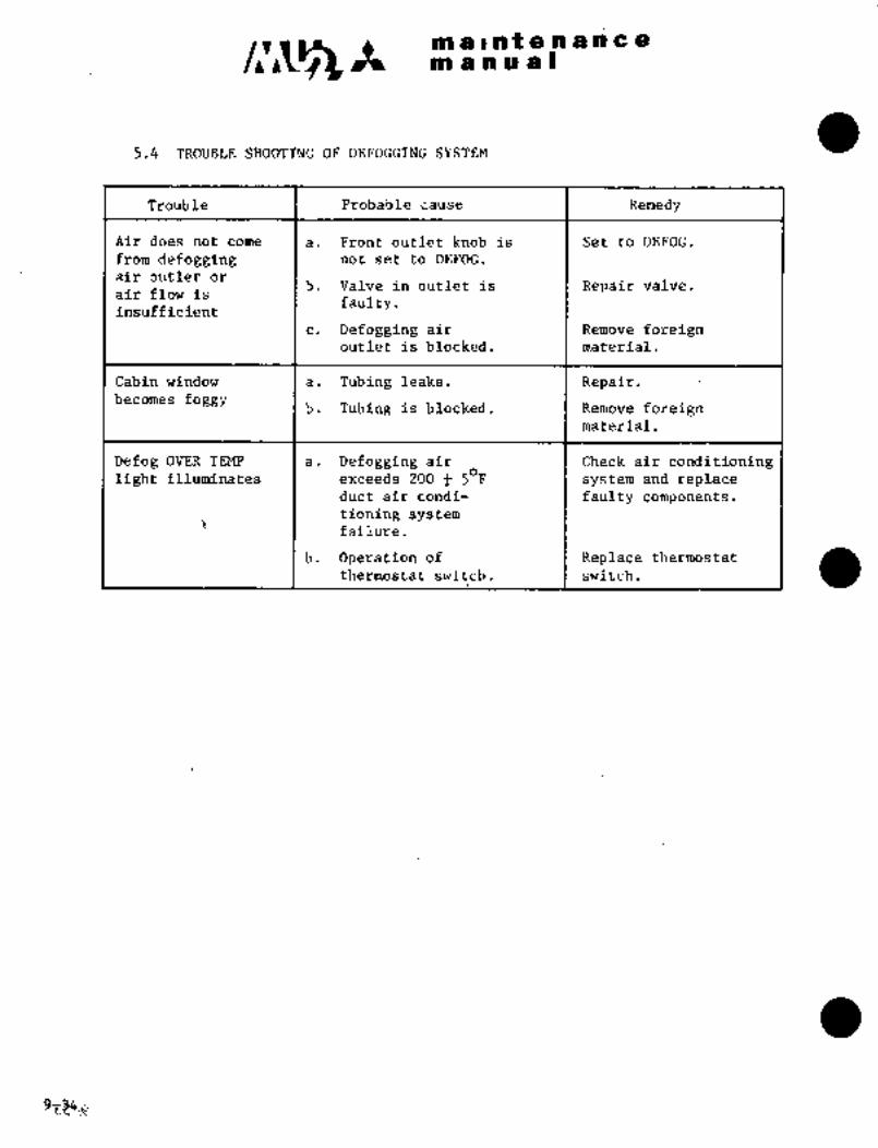
c~nmaliltenancemanual
5.4 TROUBLE SHOOTIN6 O~ DEFOGGING SYSTEM
Trouble Probable cause Remedy
Air does not come a. Front outlet knob is Set to DEFOG.
from defogging not set to DEFOG.
air outlet orb. Valve in outlet is Repair valve.
air flow isfaulty.
insufficient
c. Defogging air Remove foreignoutlet is blocked. material.
Cabin window a. Tubing leaks. Repair.becomes foggy
b. Tubing is blocked. Remove foreignmaterial.
Defog OVER TEMP a. Defogging air Check air conditioninglight illuminates exceeds 200 5 F system and replace
duct air condi- faulty components.
tioning systemfailure.
b. Operation of Replace thermostat
thermostat switch. switch.

clr~san a ant a a a a a a
an a a a a s
6. ENGINE AIR INTAKE ANTI-ICING SYSTEM (See Fig. 9-15 and 9-15A)
6.1 GENERAL DESCRIPTION
Engine air intake, cowling lip, air intake duct, pressure and temperature
sensors are providedwith anti-icer devices. The cowling lip has a
double outer skin through which bleed air from the anti-icing bleed air
valve passes. The forward lowersection of the engine air intake duct
has a double skin, andin the area of the first´•stage compressor, the back
side of ´•this surface skin forms a large cavity. The lower outer skin of
this double construction is glass fiber. Bleed air through the anti-icingbleed air valve is fed into the forward double skin section and dischargedoutboard. Bleed~ air passed’ through the anti-icing bleed air valve is
also fed to the pressure and temperature sensors located on the RH wall
in´• the air~ intake duct.
To test the system, placethe EH (RH) ENG INTAKE HEAT switch, located in
the dverhead console,tothe’0N position; the indicator light illuminates.
A yellow (amber) indicator light, located adjacent to the respectiveswitches in the overhead console, is employed to indicate the "open"position of the anti-icing bleed air valve. When the engine is not
running, the switch may be placed to ON and the indicator light will
illuminate, bdt no anti-icing function will be performed.
6;2 ANTI-ICING BLEED AIR VALVE (See´•Fig. 9-16)
The engine anti-icing bleed air valve is installed at ZONE I of the
engine~which bleeds air from the second stage compressor for engineanti-icing. It is a solenoid type valve spring loaded to close when
electric power is cut off. The micro switch for the anti-icing indi-
cating light is installed in the valve head section. Current drain of
the valve is approximately 1A/28V.
6.2.1~ REMOVAL AND INSTALLATION
.(1) Disconnect the wiring connector at valve head.
(2) Disconnect the inlet and outlet tubing at valve, and cover the
tube openings.
(3) Removebolts and’washers attaching valve, and remove the valve.
(4) Install in reverse sequence of removal.
DmMIM; RELAY
E)JQINE PIR I~JTAKE
E
lose
HEAT ~ND LleH~
Ir~-te lii~El c
eU6lhlE *IR I~TArE
H~AT Sw~rcH EA/GINE ALJ7~1-ICINGBLEED AIR VALVE:
9-(35)36 Fig 9-15A Engine anti-icing system schematic6-1-79

c~A rn ;Ita II ~a f.9 n ti c
bOoOo
tl ~Io oo
.5~0 O gOg
-L-~e
0,-j
o
1
\s
80 009
1’. First State Compressor;Impeller 5.´•´•..P;nti-Icing Bleed Air Valve
2, Second Stage Compressor/Impeller -~.:6´• Cowling Lip3. Combustion Chamber ´•7.’ Air Intake Duct
4. Bleed Air Port
Pig. 4-15 Engine anti-icing
ORIGINAL
As Received ByAT P
_i´•i
I&´• :’:5"
Pig. 9-16 Anti-icing bleed solenoid valve
9-37

CI~ It. in a i.ii t en a ii a
m a a ~u a I
6.2.2 OPERATIONAL CHECK
Perform operational check of the left and right engine anti-ice in
accordance with the following procedures.
(1) Connect DC power (battery or external power), turn Battery Keyswitch ON.
(2) Place L (R) ENG INTAKE switch to the ON position.
(3) When the anti-ice bleed air valve is "open", operating sound is
heard; the indicator light will illuminate.
(4) Place the switch to OFF.
(5) When the anti-ice bleed air valve is "closed", operating sound
is heard;the indicator light will go out.
(6) Turn Battery Key to OFF; disconnect external power (i’f used).
NOTIE
If this operational check is
performed during engine groundrun, a decrease in engine rpm
(side being checked) and an
increase in fuel flow occur
during indicator illumination.
9-38

c~3maintenancemanual
PLIPIUU~
IPlcop~-!Cfl S ~5E1PPP
pEOpELCER -ICEOZ-IcEn SrITtH
InEATE4 CvPaEUtl8auMBLocr;
DE-ICE 8AUT--IQ DLOAD HETE4
F
IWEA~a SELECd
LH PR6PDE-ICED5lnEP
t--´• RH
Al I At
pnoPDE-ICELZeLAY
pppp DE-ICE SHUVT
LOAD BUS
zsApplicable to S/N 652SA
Ipgpp~E- ICd
6blW 5 ~3PEDPELLEDoe-lcrre SVJITCH
mEarrncuaaEun
paop#-ICE 8 Aun-IQ DE-ICE
LOAD HRE8 I r IAl a IHEAI~S
BPVMBLOCI.
t3
I I I I /--------~oI
paopDE-IC~ttlmES
t--40~´•ICE. 8 /VITI-ICE
PE1-ECT SWITCH-r
Al I AZ
XePCtoPDE-icePeL~Y
pSJp DE-IR’SH~UT
I LOAD BUS
zs Applicable to S/N 661SA, 697SA and Subsequent
Pig 9-leA Propeller de-icing system schematic
6-1-799-(38A) 38B

~i´•da i./sO n ~p sBO aP
am se ai ru B
pRoEj‘ELi~ER DE-ICIMG SYSTEM
j.i DEdRIPTION
Applicable to~aircra’ft S/N 652SA
Electrically heated de-icer strips cbntainin~ two heating elementsiinner and outer, are bonded to the propeller blades for de-icing.Electrical power is supplied through brushes and slip rings. When
the PROPDE-ICE switchj loi3atCd in the overhead console, isON,current through the timer is sequentially delivered to the inner and
outer heating element of the LH or RH propelle~. The heating sequence,RH outer, RH inner, LH inner, cdmpletes the cycle in approxi-mately 136 Qeconds (34 seconds per each heating element). A loadmeter
in the overhead conSole deflects betwee~ 0.93 to l.iO to.indicat~
system op’eration.
A manual, back-up supplements the main system, should a malfunction qccur.The STAND BY PROP DE-ICE switch‘ (three‘position, center position OFF)turned to the OUTER position for 30 to 35 seconds, then to the INNER
for 30 to 35 seconds will properly operatethe prop de-ice systemmanually.
´•:NO TE
During STANDBY (manual) operation,the loadmeter will not function.
ApplicabTe’to ’dirrraft S/N 661SA, 697SA and subsequent
Electrically heated de-icer strips containing two heating elements,inner and outer, are bondedto the propeller blades for de-icing.Electrical power’ is ~supplied through brushes and slip rings. When the
I;H and RH PROP DE-ICE switch, located in the overhead console, is ON,currentis delivered through each timer to their inner and outer heatingelements sequentially. The cycle duration is 60 ´•to 68 seconds or 30 to
34 seconds when thede_ice selector switch, adjacentto the loadmeter,’ispositioned to the LH- or RH PROP ~DE-ICE position.
7.2 TIMER
Applicable to aircraftS/N652SA (See Fig. 9-17)
Thetimeris installedin the traiiing-~edge of the center wing and
distributes current´•~in the sequence described in Para. 7.1 above ~to
the de-ice s´•trips. The: Sequence of strip activation must be: rightoutboard, right’´•i~nbbara, left :outbdard, left .inboard .heaters.
Appljcable to aircraft S/N 661SA, 97SA and
The timers are attached to the´• inboard rib of the´•wing leading edgeadjacent to the fuselage fillet-; Each of the dual timers works its
propeller de-ice strips a;l;ernat’ing between the outer and inner elements
at 30 to 34~ second inter-vals.
9-39
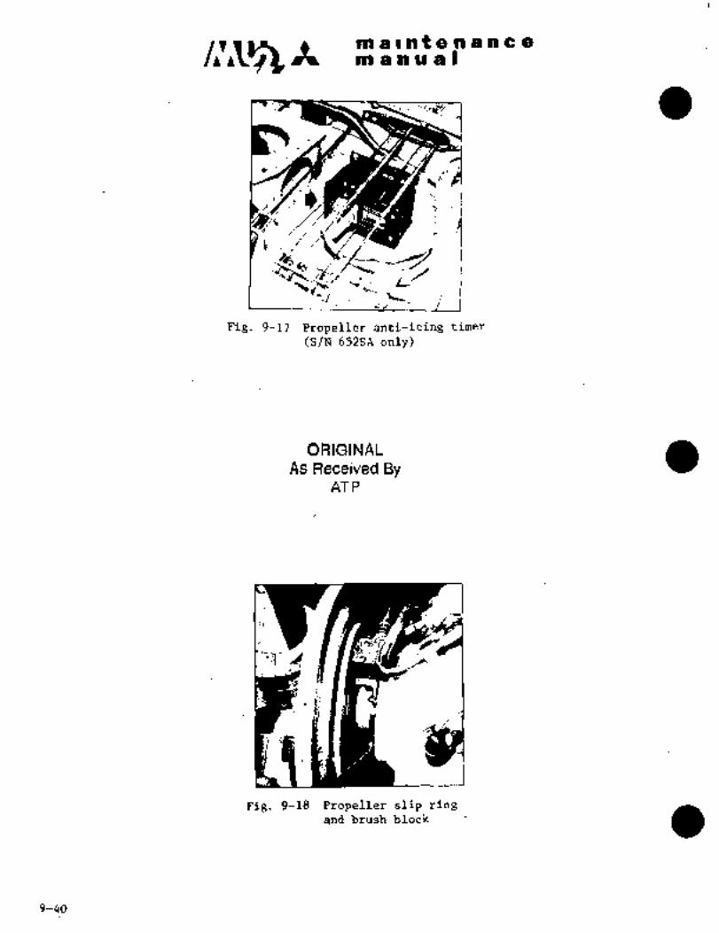
c~s m is In ~t a a a a a a
m anual
~a:1 ~´•6c,
Pig. 9-17 Propeller anti;icing timer
(S/N 652SA only)
ORIGINALAs Received By
AT P
Pig. 9-18 Propeller slip ringand brush block
9-40

C~g m alntenancemanual
a 1.3 BRUSH BLOC. b~D SLIP RrNC (See Fig. 9-18)
The slip ring is a copper ring installed in the rear section of the
propeller spinner bulkhead and consists of S´•coaxial rings for propellerouter and inner circuits and a commonreturn line. Brushes are installed
in contact with these slip rings and supply electric current to the
slip ring.
7.3.1 BRUSH BLOCK (Fig. 9-19)
(1) Removal and installation
(a) Remove engine cowling.(b) Remove brush block mounting screws and brush block at
rear of propeller spinner bulkhead.
CAUTION
If brush block is over-
tightened, the brush, may
not contact the ring freely.Torque-to 14.5 1.5 in-1F.
(c) Install in reverse sequence of removal.
C A iC T I a N
Install brush and slip ring with
care. The improper installation
may’hinder properoperation of de-
icing’systemand cause radio noise.
(2) Inspection
(a) Inspect the contact condition of the brush and slip ring after
installation, rotate the propeller 3600 tin the direction of
normal rotation only) and check for local wear and eccentricity.
S/N 652SA, 661SA, 697SA thru 730SA unless modified by SL003j30-001(b) Check the brush wear by-inserting a piece of wire (use as a
depth gauge) into the inspection hole of the brush block.
Replace the´•brush block when the wire can~be inserted more
than 0.40 inch (10.2 mm).
Aircraft modified by SL003/30-001(b) Check the~ brush wear by insetting a piece of wire, 0.10 inch
(2.5 mm) dia., (use as.a depth gauge) into theinspectionhole of the module. The module should be’replaced when the
wire can be~inserted to a depth of 1.08 inch (27.4 IIIln)n) and
must be replacedwhen the depth is 1.14 inch (29.0mm).
NOTE
Some modules have a rod which protrudes throughthe inspection hole. As the brush wears, the rod
moves into the hole. With a piece of wire, check
the depth of the rod. When the depth becomes 0.23
inch (6.0 mm), the module should be replaced. Whenthe depth becomes 0.30 inch (7.5 mm), the module
must be replaced.
9-15-80 9-41

NE a I ~n t a a a a c a
manual
-~te 20 SLIP RING SLIP RINB-- ROTATIONROTATION C~20
ff)
125 20 20125
13.is Mn) ga (1. IR WMI
j/llllBRUSH BLOCK-’ I _,L j BRUSH BLOCK-/
30 003INSPECTION HOLE INSPECTION HOLE-
Aircraft S/N 652SA Unless Aircraf; S/N 661SA, 697SA thru 730SA
Modified By SL003/30-001 Unless Modified By SL003/30-001
SLIP RING
iFWD
SLIP RING
1 1 _e I-f r -f
0,03 0.09 rN, 20 20 0,03 0.09 IN,
(0,76 2,29 nn) (0.76 2,29 ru4)
BRUSH BLOCK BRUSH BLOCK
Aircraft S/N 652SA´• If Aircraft S/N 661SA, 697SA thru 730SA
Modified By SL003/30-001 If Modified By SL003/30-001
Fig 9-19 Installation of brush block
7.3.2 INSPECTION AND ADJUSTMENT OF SLIP RING
(1) Inspection
With a dial gauge installed, check for uneven wear or wobble by rotatingthe propeller. If run-out´•over 3600 rotation is over 0.005 inch
(0.13 rmn) total or exceeds 0.002 inch (0.05 wm) are, adjust in the
following manner,
NOTE
Push aft on propeller to eliminate play.in propeller thrust bearing while turning,
9-426-1-79
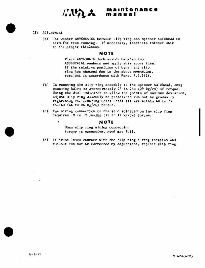
as a s os t a a a a a a
as a.a a a i
(2) Adjustment
(a) Use washer AN960C416L between slip ring and spinner bulkhead to
shim for true running. If necessary, fabricate thinner shim
to the proper thickness.
NOTE
Place AN963R416 lock washer between two
AN960C416L washers and apply shim above them.
If therelative position of brush and slipring has changed due t´•o the above operation,readjust in accordance with Para. 7.3.1(2).
(b´•) In´•mounting.the slip ring assemblyto the spinner bulkhead, snug
mounting bolts’to approximately 25 in-lbs (29 kg/cm) of torque.Using the dial indicator to allow the points of maximum deviation,adjustslip ring assembly to prescribed run-out by graduallytightening the mounting bolts until all are within 40 to 75
in-lbs (46 tog6 kg]cm) torque,
(c) The wiring connection to the stud soldered on the slip ringrequires 10 to 1? in-lbs (12 to 14 kg/cm) tbrque.
NOTE
When slip ring wiring connection
torque is excessive, stud may fail.
(d) If brush loses contact with the slip ring during rotation and
run-out can not be corrected’by adjustment, replace slip ring.
6-1-799-42A(42B)

a8 a Int a 918 a a a
nl a a a a I
a 1.,.3 MEASUREMENT OF INSULATION RESISTANCE OF BRUSH BLOCK
(1) To determine whenopen or short circuit or high resistance is presentin the brush block, use a low range multi-tester to measure resistance
from the face of the brush to its receptacle´•pin or terminal stud.
The probe contacting the brush should have an area of 1/16 sq. in.
minimum. If the resistance is over 0.013 ohms, locate and repairthe cause of excessive resistanceor replace the brush.
(2) Check the insulation resistance between the connector pins land pinstoconnector shell)-or terminal studs. The resistance should not
be less than 0.5 megohms after one minute. Should the resistance
be less than0.5 megohms, check for a short between the brush leads
and repair in accordance with B.F. Goodrich Overhaul Manual ReportNo. 68-04-714.
7,4 DE-ICER (See Fig. 9-20)
The de-icerS are rubber stripsglued on theleading edge of the propellerblades and ~ontaining resistance heating wire hereinafter referred to
as ~ieater) inside. Theheater consists of 2 circuits, one for de-icing.b~ the outer half of the blade and one for the inner half. The power
supply wire to and return wire from the heater are connected to sliprings with´•lead strips and screws.
7.4.1 MEASUREMENT OF HEATER ELEMENT RESISTANCE (See Fig. 9-21)
There are two methods for checking the resistance.of the heating elements.
First., check the resi‘stance of inner and outer elements of the propeller.The parallelresistance of three elements should be 1.55 to 1.78 ohms
and of four elements should be 1.15 to 1.?3 ohms between the power
supply and return (ground) wires. If not, then check the resistance
of each element to be within 4.58 to 5.26 ohms between the power supplyand return -(groulid) wiiies~.
9-436-1-79

m a II a t a a a a a a
m a a a a I
I ’L fip~
Fig. 9-20´•’´•De-icer boots Fig. 9-21 Electrical connection
of de-icer boots
7.5´•. OPERATIONAL CHECK OF TIMER
Operational check of the timer should be performed in accordance with
B.F. Goodrich:Malntenance Manual (Report No.68-O4-712).
7.6 OPERATIONAL TEST OF PROPELLER DE-ICING SYSTEM
7.6..1 TEST FOR-ENTIRE SYSTEM
.´•Applicable~to aircraft _S/N ~652SA
(I) Turn. aircraft power ON, use ofAPU’is preferred, and close the
necessary circuit breakers.
(2) Placethe PROP DE-ICER switch in the overhead console ON. Observeand confirm the loadme’ter needle movement from the timer auto-
matic cycling of 30 to 34 seconds. Touch each propeller bladede-icer with bare hand to confirm all blades are heated uniformlyand ia proper sequence.
Place the switch to OFF and restore the system to the originalcondition.
ORIGINAL
As Received ByAT P
9-44

clr~nl a~i nt a a a n a a
nl a a a a)
Applicable to airct~ift_S/N ’661SA;’697SA and’sdbsequent
(1) Turn aircraft power ON, use of APU is preferred, and close requiredcircuit breakers for LH and RH PROP DE-ICE.
(2) Turn the HEATER CURRENT´•SELECT swith to LH PROP position and
place the LH PROP DE-ICE~switch ON.
(3) Observe and confirm deflection of load meter needle.between 0.85
andl;02 at: time intervalsof 30 to 34’second~. ~ouch each
propeller blade´• de-icer with bare hand and confirm uniform heat-
Ing ai~d proper sequence:per’Para. 7.1 and 7.2.
(4) Place LH PROP DE-ICE.s~itch OFF.
(5) ~Turn HEATER CURRENT SELECT’switch to RH ´•PROP position and placeRHPROP DE-ICE switch ON.
(6) Perform~:steps ’(2) and (3) above for RH´• prop blade de-icer.
(7) Place RH PROP IjE-ICE switch OFF.
(8) Turn aircraft power~OFF, disconnect APU (if used).
7.6.2´• ELECTRICAL LOAD TEST
to aircraft ~S/N 652SA
(1) Remove the overhead switch console´•and connect an´• ammeter’ (25 to
30 Amps) to the.´•load s~de bf PROP ´•DE-ICER switch.´•----i;---;1~.
_.
-1;=:-----´•´•
(2) Place the propeller de-icing switch PROP DE-ICER in the overhead
console ON.´• When power is supplied from the aircraft batteryonly, the ammeter must read´•~12 to15.5 Amps, and´•the loadmeter
must read´•0.7 tq´•0.9. .When power is supplied from the generator,with the engine running at Ground’ Idle, the ammeter must read 14
to 18 Amps and the loadmeter must read 0.8 to 1.0.
td aircraft S/N_6:61SA,. 697SA
(1) Connect ammeter-(25 fo 30Amps)~in line to terminal B of the prop
timer. When power is supplied to the de-icer boots, the ammeter
should read 17, to 20 Amps while the loadmeter.deflects between 0.85
tcr 1-.02 forboth LH and RHpropde-ice timers.
9-45. _i:

iti is a U a IIm a a at a a a a c a
7.7 TROUBLE SHOOTING PROPELLER DE-ICING SYST~M
Trouble Probable cause Remedy
Load meter does not a. Fai~lty switch. .I Replace switch.
deflect when switchb. Power source is dis- Check electrical poweris turned on
connected i. system.
c. Faulty loadmeter, Check and/or replace.fuse or shunt wire.
d. Faulty timer. Replace timer.
e. Wire broken. Repair wire.
Heating is out of a. Faulty wiring. Check wiring.sequence
Load meter indica- a. Corresponding de- Replace or repair wire
tion is too low icer or wiring is or de-icer.
broken.
b. Contact of corres- Correct attachment
pending slip ring conditions.
and brush is poor.
Load meter indica- a.´• Short circuit of Replace or repair.tion is too high de-icer or circuit.
b. Short circuit of Replace diode.
diode.
Brush wears I a. Brush is attached I Correct brush attach-
improperly. ment.
b. Slip ring is I Adjust slip ring attach-
eccentric. ment or replace slipring.
Radio noise is pro- a. Brush are. Polish or clean slipduced when de-icer ring and brush and
is operated adjust attachment.
Replace brush or slipring if necessary.
b. Faulty contact of Check circuit and over-
wiring connection. I haul connector and/orterminal section.
c. Faulty switch. Apply jumper to switch
and replace switch if
noise disappears.
9-46

c~A m a I n’0 a a a a a a
´•m a a a a I
8. PITOT AND STATIC ANTI-ICING SYSTEM
8.1 GENERAL DESCRIPTION
The anti-icing of the pitot tubes and static ports is carried on con-
tinuously by electrical heaters installed in the~ units. These circuits
are protected by the OVERHEAD circuit breakers. The system is operated
by means of LH and RH PITOT STATIC HEAT switch located in the over-
head switch console.
STAT(C IPITOfNBE
PoRT
II~T
Pltoy roea 1
sn\ncPwrHCIT SVlrcy Aircraft S/N 652SA
(HEATFP QInRwr s~ctn
biEa;7tR
ST~T,C
poRy ~BEt~ I
AUT’-’CE’DC-ICP
iLMDCIPT~R
PITDT To8E1ET*nC PDQTAUTI-ICE S~LAlr
~O
ALm-ICE) D~-ICELa4Dnlirr~nrorrusElSUecT swlml
d~nC PoaT
HUr SVIICY
Aircraft S~N 661´•’SA, 697SA And Subsequent
Fig 9-21A Pitot and static anti-icingsystem schematic
8.2 MAINTENANCE PRACTICES
8.2.1 STATIC PORT ANTI-ICE HEATER
A. Removal and Installation
(1) Disconnect the electrical wiring at the static port.
(2) Disconnect the plumbing.
6-1-79 9-47
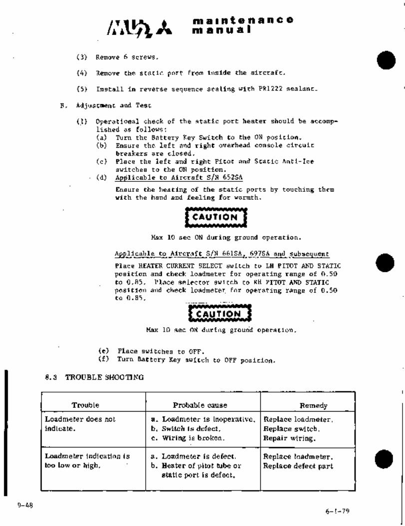
m a Int a a a a a a
m a a a a i
(3) Remove 6 screws.
(4) Remove the static port from inside the aircraft.
(5) Install in reverse sequence sealing with PR1222 sealant.
B. Adjustment and Test
(1) Operational check of the static port heater should be accomp-lished as follows:
(a) Turn the Battery Key Switch to the ON position.Ensure the left and right overhead console circuit
b~eakers are closed.
(c) Place the left and right Pitot and Static Anti-Ice
switches to the ON position.(d) to Aircraft S/N 652SA
Ensure the heating of the static ports by touching them
with the hand and ´•feeling for warmth.
CAU’IION
Max 10 sec ON during ground operation.
AZjplicab;le’td Aircraft S/N’661SA, 69 7SA and’s~ilj seguent
Place HEATER CURRENT SELECT switch to LH PITOT AND STATIC
position and check loadmeter for operating range of 0.50
to 0.85. Placeselector switch to RH PITOT AND STATIC
position and check loadmeter for operating range of 0.50
to 0.85.
CAUTION
Max 10 sec ON during grourid operation.
(e) Place switches to OFF.
(f) Turn Battery Key switch to OFF position.
8.3 TROUBLE SHOOTING
Trouble Probable cause Remedy
Loadmeter does not a. Loadmeter is inoperative. Replace loadmeter.
indicate. b. Switch is defect. Replace switch.
c. Wiring is broken. Repair wiring.
too low or’ high.´• I b; Heater of pitot tube or Replace defect part
Loadmeter indication is a. Loadmeter is defect. Replace loadmeter.
static port is defect.
9-456-1-79.

c~s~81 aln enanceIm a a a al
8.2.2 PITOT TUBE ANTI-ICE HEATER
A. Remotial and Installation
(1) Remove pilot tube from pitot tube fitting inside the aircraft.
(2) Remove connector for heater from inside the aircraft.
(3)´• Remove pitot tub~. Remove’ heater by removing 4 screws
attaching heater..
(4) Install in reverse sequence of ´•removal, sealing as required.
B. Adjustment and Test
(1) Operational check of the pitot tube heater should be accom-
plished as follows:
(a) Turn the Battery Key switch to the ON;position.(b) Ensure the left and right overhead console circuit
breakers are closed.
(c) Place the left and right Static and Pitot Anti-Ice
swit~hes to the ON position.(d) to Aircraft S/N 652SA
Ensure the heating of the pitot tubes bytouching them
with the hand and feeling for warmth.
CAUTION
Max 10 sec ON during ground.operation.
to AirdraftSIN_661SA, 697SA
Place HEATER SELECT switch to LH PITOT AND STATIC
position and check loadmeter for operating rangeof 0.50
to 0.85. Place selector switch to RH PITOT AND STATIC
position and.check loadmeter for operating range of 0.50
to 0.85.
CAUTION
Max 10 sec ON during ground operation;
(e) Place switches to OFF.
(f) Turn Battery Key switch to OFF position.
a
9-49
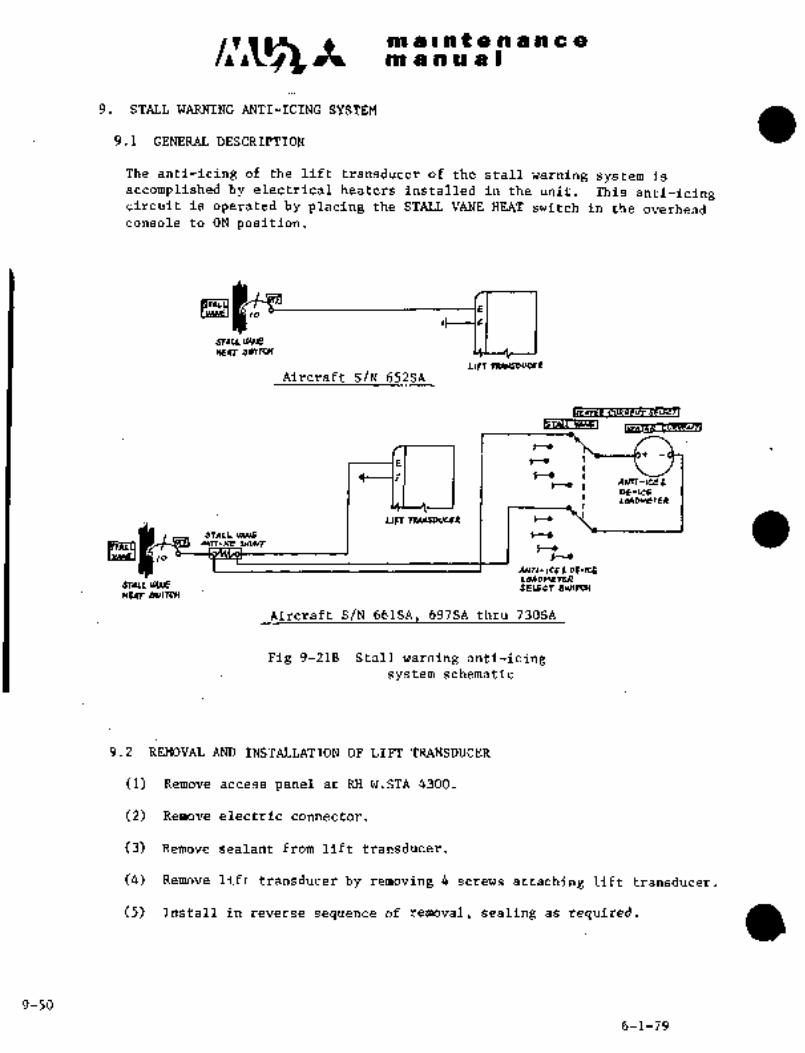
m a Int a a a a a a
n~ a a a a I
9. STALL WARNING ANTI-ICING SYSTEM
9.1 ´•GENERAL DESCRIPTION
The anti-icing of the lift ~ransducer of the stall warning system is
accomplished by electrical heaters installed in the unit. This anti-icingcircuit is operated by placing the STALL VANE HEAT switch in the overheadconsole to.ON position.
c
JTAU
HEAT SUNTCH
U~T raAIIsDvcEn
Aircraft S/N 652SA
SELi;Cfl
BTACLYArSI
I--´• I
F t~ It-´• Aur~-aEB
DE-ICELWD~IErrR
LlrT 7E4L[SDUCEI t-´•
SfAIL V~W6 tj
tp~yI~n-laE SHLLlr
t--´•to t-´•
ANn-lcEa DE-RE
~ALLVAMEHEAT 1YIITCH
Aircraft S/N 661SA, 697SA thru 730SA
Fig 9-21B Stall warning anti-icingsystem schematic
9.2 REMOVAL~AND INSTALLATION OF LIFT TRANSDUCER
(1) Remove access panel at RH W.STA 4300.
(2) Remove electric connector.
(3) Remove sealant from lift-transducer.
(4) Remove lift transducer by removing 4 screws attaching lift transducer
(5) Install in reverse sequence of removal, sealing as required.
9-50
6-1-79

c~C1 no a 0 or t a n a n a ano a a a a I
a L~´•9 OPERATIONAL CHECK OF LIFT TRANSDUCER
Operational~ check of the Stall Warning Anti-Ice System should be
accomplished as follows:
(1) Turn the Battery Key switch to the ON position.
(2) Ensure the overhead console circuit are closed in.
(3) Place the STALL VANE´•HEAT switch toON.
(4) Agpli6a~b-le to Aircraft S/N 652SA
Ensure ~the heating of the lift t+ansducer by touching it with the
hand and feeling for warmth.
CAUTIBN
Max 10 sec ON during.ground operation.
6B1SAI
Turn HEATER CURRENT SELECT switch to STALL VANE position and check
loadmeter for operating range of 0.30 to 0.70.
CAU T )8N
Max 10 sec ON during ground operation.
(5) PLace.switch~ to OFF.
(6) Turn Battery’Key switch to OFF position.
9.4 TROUBLE SHOOTING
Trouble Probable cause Remedy
Lift transducer does a. Broken wiring Repair wiringnot heat b. Defective switch Replace switch
c. Defective lift trans-
ducer heating element Replace lift transducetLoad meter does a. Broken wiring Repair wiringnot indicate (*1) b.Defective shont Replace shunt
c. Defective load meter Replace load meterLoad meter indication a. Defective shunt Replace shuntis too low or high (*1) b. Static port or pitot
tube heating element
´•I)*1 Aircraft_S/N 66iSA, 697SA thru 730SA661
defective Replace defective part~
6-1-79 9-51
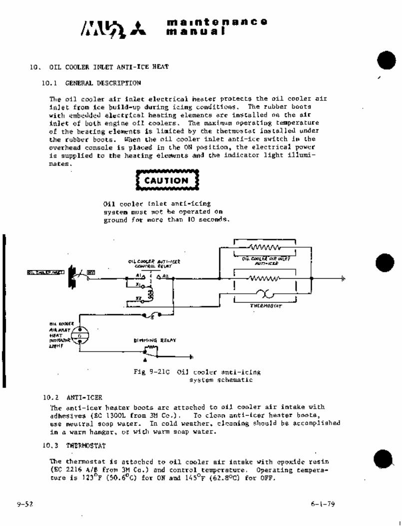
malntenane a,
m a a a a I
10. OIL COOLER INLET ANTI-ICE HEAT
10.1 GENERAL DESCRIPTION
The oil cooler air inlet electrical heater protects the oil cooler air
inlet from ice build-up during icing conditions. The rubber boots
withembedded electrical heating elements are installed on the air
inlet of both engine oil coolers. The maximum operati~g temperatureof the heating elements is limited by the thermostat installed under
the rubber boots. When the oil cooler inlet anti-ice switch in the
overhead console is placed in the ON position, the electrical power
is supplied to the.heating elements and the indicator light illumi-
nates.
CAU T ION
Oil cooler inlet anti-icing
system must not be operated on
ground for more than 10 seconds.
I.,1...,
I
I011 COoLER AIP AAe~
OILCOOLER AOTI-ICEP aun-IC~CoNr~oL IPELCIY
nc~ f At I I 1IO~L Cabirp iU~FTI
I r ITHELNOSTLI~
OIL COOLE~
kR ~rT
HEAT GIIJ~ICAToR O plnMI~G REVIY
uttnr
Fig 9-210 Oil cooler anti-icingsystem schematic
10.2 ANTI-ICER
The antilicer heater boots are attached to oil cooler air intake with
adhesives (EC’~1300L from 3M Co.). To clean anti-icer heater boots,
use neutral soap water. In cold weather, cleaning should be accomplishedin a warm hangar, or with warm soap water.
10.3 THERMOSTAT
The thermostat is attached to oil cooler air intake with epoxide resin a(EC 2216 A/B from 3M Co.) and control temperature. Operating tempera-ture is 1230F (50.60C) for ON and 1450F (62.80C) for OFF.
9-52 6-1-79

c~c;s m a I ~n t a a a a a a
m asa a a B
10~. 4 OPERATIONAL CHECK
(1) Turn the Battery Keyswitch to the ON position.
(2) Check for closed condition of the LH and RH overhead circuit
breakers.
(3) Place LH and RH OIL COOLER HEA~ switch to the ON position.
(4) Check LH and RH OIL COOLER HEAT indicator lights for illumination.
(5) Confirm system is operational by touching the left and right
engine oil cooler inlet heat boots with the hand.
(6)- Place the LH and RH OIL COOLER switches to.the OFF position.
(7) Turn the Battery Key -switch to OFF.
10.5 TROUBLE SHOOTING
Trouble Probable cause Remedy
Indi’cator’light does I a. Faulty light. Replace.
not il~umlnate´•with Checkwire connectionb. Poor wire connec-
system ONtion. with´• ohlmneter.
Boots will not heat a. Poor wire connec- Check ~iire connection.
tion.
b. Faulty relay. Replace relay.
c. Faulty heating Replace boot.
element in boot.
d. Malfunction in Replace.thermostat..
6-1-79 9-53

CHAPTER
INSTRUMENTS

TPI aintenancemanual
X
INSTRUMENTS
CONTENTS
1, GENERAL.....:. 10- 1
1.1 GENERAL DESCRIPTION 10- 1
1.2 RANGE MARKING 10- 1
1.3 INSTRUMENT PANEL 10- 1
2. VACUUM SYSTEM 10- 9
2.1 GENERAL DESCRIPTION 10- 9
2.2 EJECTOR 10-(11)12
2.3 RELIEF VALVE 10-(11)12
2.4 VACUUM GAUGE 10-(11)12
2.5 AIR FILTER 10-(11)12
2.6 WARNING SWITCH 10-14
2.7 OPERATION AND ADJUSTMENT OF VACUUM SYSTEM 10-14
2.8 LEAK TEST 10-15
2.9 TROUBLE SHOOTING 10-16
3. PITOT AND STATIC PRESSURE SYSTEM 10-(17)18 I3.1 GENERAL DESCRIPTION 10-(17)18
3.2 LEAK TEST OF STATIC PRESSURE LINE 10-20
3.3 OPERATIONAL CHECK OF STATIC PRESSURE LINE 10-20
3.4 LEAK TEST OF PITOT LINE 10-21
3.5 OPERATIONAL CHECK OF PITOT LINE 10-21
4, FLI~ INSTRUMENTS 10-21
4.1 ALTIMETER 10-21
4.2 AIRSPEED INDICATOR 10-24
4.3 RATE-OF-CLIMB INDICATOR 10-26
4.4 ATTITUDE GIRO 10-27
4.5 TURN BANK INDICATOR 10-28
4.6 CLOCK 10-28
3-31-90 10-i

m a i n t a re a n ce
qd IIP~BL
4.7 TVLACNETIC COMPASS´•´•´•´•´•´•´•´•´•´•´•´•´•´•´•´•´•´•´•´•´•´•´•´•´•´•´•´•´•´•´•´•´•´•´•´•´•´•´•´•´•´•´•´• 10-25
4.8 ELECTRICCOMPASS CALIBRATION´•´•´•´•´•´•´•´•´•´•´•´•´•´•´•´•´•´•´•´•´•´•´•´•´•´•´•´•´•´• 10-30
4.9 AILERON-TRIhl POSITIONINDICATOR 10-32
4.10 TROUBLE SHOOTING 10-33
5. FUEL QUANTITY INDICATOR 10-35
5.1 DESCRIPTION 10-35
5.2 WING TANI(FUEL QUANTITYINDICATOR 10-35
5.3 TI’P TANI(FUEL QUANTITYINDICATOR 10-35
5.4 AMPLIFIER´•´•´•´•´•´•´•´•´•´• 10-36
5.5 CENTERTAIU’I~UNIT´•´• 10-36
5.6 OUTER TANI( UNITS 10-36
5.7 TIP TANI(UNITS 10-36
5.8 TESTOFINDICATOR´•´•´•´•´•´•´•´•´•´•´•´•´•´•´•´•´•´•´•´•´•´•´•´•´•´•´•´•´•´•´•´•´•´•´•´•´•´•´•´•´•´•´•´•´• 10-36
5.9 ADJUSTMENT OF MAIN TANII FUEL QUANTITY INDICATOR
susTEM´•´•´•´•´•´•´•´•´•´•´•´•´•´•´•´•´•´•´•´•´•´•´•´•´•´•´•´•´•´•´•´•´•´•´•´•´•´•´•´•´•´•´•´•´•´•´•´•´•´•´•´•´•´•´•´•´•´• 10:395.10 ADJUSTMENT OF TIP TANI( FUEL QUANTITY INDICATING
SYSTEM 10-39
5.11 OPERATIONAL CHECI( OF FUEL QUANTITY INDICATOR 10-40
5.12 CHECI( OF LOW LEVEL WARNING LIGHT 10-40
5.13 TROUBLE SHOOTING 10-40
6. ENGINEINSTRUMENTS 10-41
6.1 TOR&UEMETER 10-41
11 6.2 TACHOMETER 10-41-6
6.3 UNTERSTAGE TURBINE TEMPERATURE INDICATOR 10-44
6.4 OTLPRESSURE INDICATOR 10-45
6.5 OILTEMPERATURE INDICATOR 10-45
6.6 FUEL FLOW SYSTEM 10-46
6.7 FUEL PRESSURE INDICATOR 10-46
6.8 TROUBLE SHOOTING´•´•´•´•´•´•´•´•´•´•´•´•´•´• 10-47
7. OTHERINSTRUMENTS 10-48
7.1 VOLTMETER-AMMETER 10-48
7.2 CABINALTITUDE DEFFERENTIAL PRESSURE INDICATOR 10-48
7.3 CABINRATE-OF-CLIMB INDICATOR´• 10-48
7.4 OUTSIDE AIR TEMPERATURE INDICATOR 10-48
7.5 TROUBLE SHOOTING 10-49(50)
10-ii 10-7-98

c~ ct ai~ altifenancesn a a a a I
1. GENERAL
´•.1.1 cFNenaroescnrPTIoll
The instruni~nt panel is installed in front of the pildts, and consists ofLH instrument panel, center instrument panel, and RH instrument panel. LH
and RH instrument panels are mounted on the frames with quick fastenersto facilitate removal. The center instrument panel forms integral con-
struction with frames and is supported by 6 shock mounts on the lower
sectioli~ and 4 on the upper sectri~ils. Instruments are lighted by pillarlights above each instrument. Brightness of lighting is controlled byrheostats (PILOT FLT INST, COPILO~ FLTINST and ENG INST) installed in
the dverhead switch console. Switch panels consist df LH and RH switch
panels installed below LH and RH instrument panels at a 200 angle, and
the oveihead switch console’is located~ in the ceiling above the
pilot and co-pilot. The ~swifch panels are edge-lighted by bulbs´• mounted
in thepanelfaces. ’Brightness´•of~:the lighting is controlled by’rheo-stats (COPILOT nT INST, PANEL and ENG INST) located in the overhead
switch console. Aircraft power source 28 VDC is supplied to the lightsthrough circuit breaker INST PANEL.
1.2 RANGE MARKING
See Figure 10-1 for range~markingof major instruments,
1.3 INSTRUMENT PANEL
Various kinds of instruments are installed on the LH, RH and center
instrument panels as shown in Figure 10-2. Instrument panels ~are made of
aluminum alloy sheet 1/8.inch ~3.2 mm) in thickness and arepainted with
matfe acry~ic.iacquer and lighteh.’by pillarlights. For vibration pre-
vention, rubber type shoclimounts are used. Rubber type shock mounts
should beinspected formounting condition andvibration preventioneffects. When ~excessive stre~tching.is observed or vibration preventioneffect’is abnormal, shock mounts should be-replaced,
1.3.1 REMOVAL AND INSTALLATION OF LH INSTR~ENT PANEL. (See Fig. 10-3)
(1) Disconnect hose of pitot, static pressure and, vacuum system ´•at
union, F.STA~´•1440, back of-:instrument panel.
(2) Disconnect plug at connection box, back-of center pedestal.
(3) Remove fasteners attaching´• LH instrument panel.
(4) Pull control wheel and ´•turri:td~the ´•right’, and remove LH instru-
ment paneli
(5) Install in reverse sequence of removal;
1.3.2 REMOVAL AND INSTALLATION OF RH ´•INSTRUMENT PANEL (See Fig. 10-3)
(I) Disconnect hose of pitot, static pressure and vacuum system at
union, F.STA 1440j:back of instrument panel.
(2) Discdnn‘edt´• plug at conne’ction box, back, of center.pedestal.
10-1

clr~s m ;a~nt e.nance
m a a a at
(3) Remove fasteners attaching RH instrument panel.
(4) Pull control wheel and turn to the left, and ;remove RH instru-
ment panel.
(5) Install in reverse sequence of removal.
10-2

maintenanceman ual
TORQUMFTER (2 To)OIL TMP IND (OC)
x e5 Oro1O0 8R -40
R 100Y -40 To 556 5510110
Y UOro127R 127
011 PRESS IND (PSI) FUEL PRESS IM) (851)160
R 40 PSI 200 R 15 /L’iooY 40To70 I~ --~n\ v 15 To 20 Nn PRESSC 70To120 6 20To8O 80
R 120 80 Y 80To9O 20011 6040 R 90 90
BATTERY TEMP IND (OF) VACUUI1GAU6E (IN-HG)i 5
G 0To120 R 4.0
R 150 To 190 OOG 4.2 To 5.0Y 120To15O
9 o
(7 O
O O
Aircrafe S/N 321SA, 348SA,
Aircsaft S/N 313SA 349SA 350SA thru 394SA
TACHOMETER (1 RPn)TACHOMETER (2 RPII)
R 50 To 76,5Y 6510961 ;tb~,o 11
6 96ro1001 )Ii;)Y 76.5To 96G 96 ro 100
Y 100To1011 n´•cl*1
rIlC(NI W 72 19 101 po
R lau Y 100 ro 101 ~060
R 101
6 GREEH
C~:rl Y YELLOW
R RED
I I W WHITE
Fig. 10-1 Instrument range markings (1/2)
5-2-94 10-3(4)

c~5malnt a. nan68
P P u~F9
~01 a91Ual ´•Qr
AirCraft S/N 65iSA
ogh;~
;xso 5
I ;atss´•si
TS ‘b,J’ 15
,o
\~´•(CC,3P
AIRSPEED IND.CABIN ALTITIIOE DIFF, PRESS. IND
W 80T0120KTG’ 1O11TO250KS t O TO 5.25 psr
R 250 KTR 5.25
subsequent
1~so/ ~;D"´•:
80 O ~´•:iG: ,,,~p
.I
x
KN~S loo_j~ 45
lso B‘j~ 76200 k´•i;
30
AIRSPEED InD (KTS) CABIN ALTITUDE DIFF PRESS IND (PSI)
W 81 To 120 G O TO 6.00G 106 To 250 R 6.10R 250
Aircraft S/N 652SA, _unless modified Aircraft S/N 661SA, 697SA and
by Kit brawing K926A-8202 subsequent, and aircraft modified
by’ Kit Drawing K926A-8202
INTERSTAGE TURBINE TEMP IND (OC) INTERSTAGE TURBINE TEMP IND (OC)
G O TO 92j ~12 G O TO 9239.5 1910
1´•2
R 923 R 923-10
W 1149 1Uil W 1149
8.5 ~loo 276 8 6 4
G GREEN
Y YELLOWW WtjlTER RED
Fig. 10-1 Snstrument range markings (2/2)
19-5
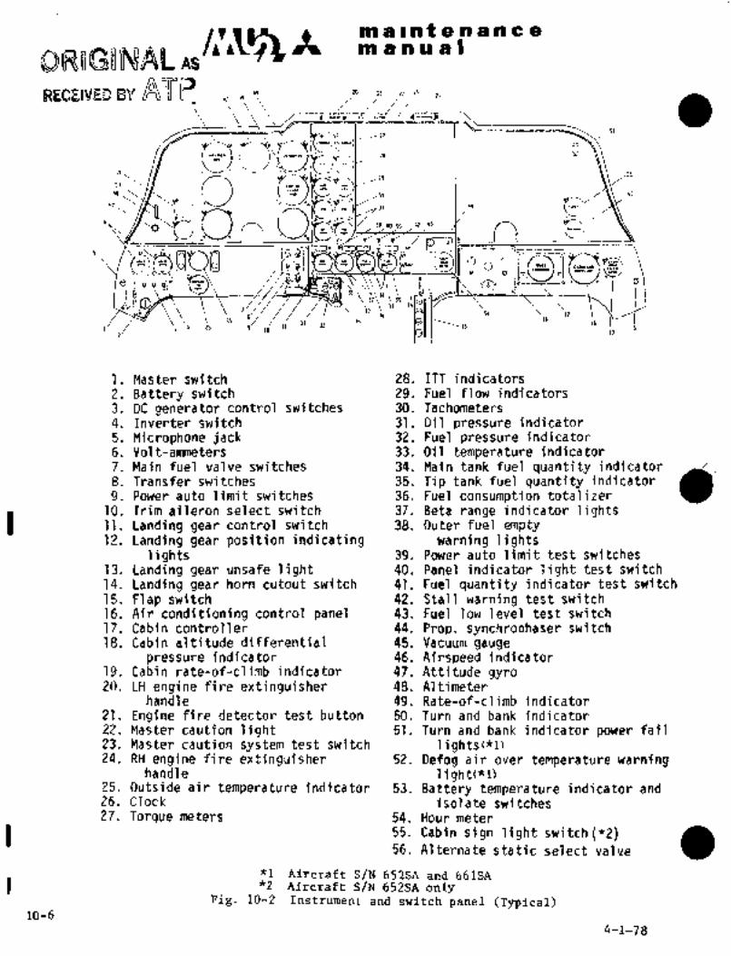
Pn a B nt a a a a a a
manual
V
26~
Q ".pU~C--50. ,JO
51. 8-~
,i‘’g
oo
´•o ´•o ~Z´•
35
i. Master switch 28. ITT indicators
2. Battery switch 29. Fuel flow indicators
3. DC generator control switches 30. Tachometers
4. Inverter switch 31. Oil pressure indicator
5. Microphone jack 32. Fuel pressure indicator
6. Volt-ammeters 33. Oil temperature indicator
7. Main fuel valve switches 34. Main tank fuel quantity indicator
8. Transfer switches 35. Tip tank fuel quantity indicator (I)9. Power auto limit switches 36. Fuel consumption totalizer
1O. Trim aileron select switch 37. Beta range indicator lights11. Landing gear control switch 38. Outer fuel empty12. Landing gear position indicating warning lights
lights 39. Power auto limit test switches
13. Landing gear unsafe light 40. Panel indicator light test switch
14. Landing gear horn cutout switch 41. Fuel quantit~iindicator test switch
15. Flap switch 42. Stall warning test switch16. Air conditioning control panel 43. Fuel low level test switch
17. Cabin controller 44. Prop. synchrophaser switch
18. Cabin altitude differential 45. Vacuum gauge
pressure indicator 46. Airspeed indicator19. Cabin rate-of-climb indicator 47. Attitude gyro20. LH engine fire extinguisher 48. Altimeter
handle 49. Rate-of-climb indicator21. Engine fire detector test button 50. Turn and bank indicator22. Master caution light 51. Turn and bank indicator power fail23. Master caution system test switch li9htsc*1~24. RH engine fire extinguisher 52. Defog air over temperature warning
handle light("l)25. Outside air temperature indicator 53. Battery temperature indicator and26. Clock isolate switches27. Torque meters 54. Hour meter
55. Cabin sign light switch(*2)56. Alternate static select valve
"1 Aircraft S/N 652SA and 661SA"2 Aircraft S/N 652SA only
Fig. 10-2 Instrument and switch panel (Typical)10-6
4-1-78
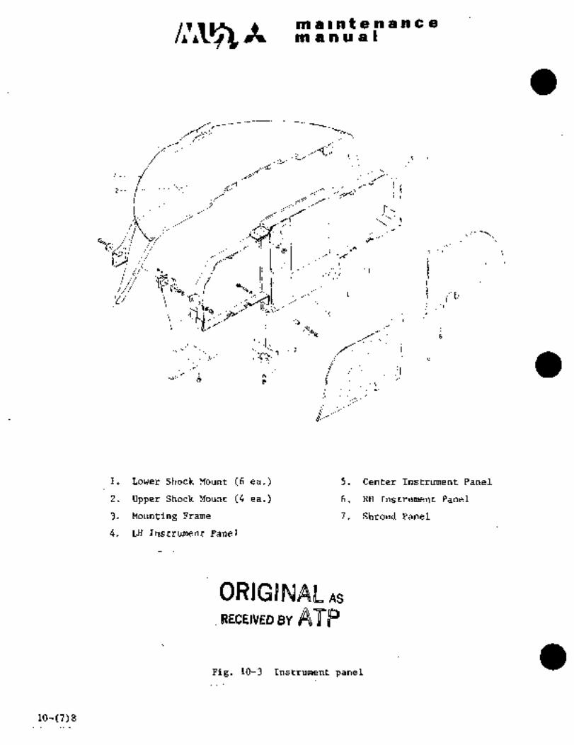
c~sm a Int a a a a a a
pn a a a a I
jj7
2--´•
--.~J! i
´•i
t:-1 1I/iP~
V g‘;´•´•1
~´•´•r h
o´• ...~.1
’’c~F´•,
IiIi
i
d
i. Lower Shock Mount (6 ea.) 5. Center Instrument Panel
2. Upper Shock Mount (4 ea.) 6. RH Instrument Panel
3. Mounting Frame 7. Shroud Panel
4. LH Instrument Panel
BWI@INAL As
RECEIVEB BY
Pig. :10-? Instrument panel
to-(7)8

..1´•: i:
iri; a nane a
m$nual
REMOVAL AEjD IE;jSTALLAT~ON OF RADIO PANEL
(1) Remove quick fasteners attaching radio panel.
~2) Dis~onnect electric connector for radio equipinent.
(3) Reinove radio pai~el.
(4) Relnstall in reverse sequence of removal.
1.3.4 REMOVAL AND INS~ALLATION OF SHRO;UD PANEL
(1) ´•After removing quick fasteners, pull out LH and RH instrument panel.
(2) Remove 4 shock Illounts atta~hed on upPer section of shroud panel.
(3) Remove screws and remove panel.
(4) Remove 4screws and 4 bolts attaching shroud panel to frame and
remove the panel.
(5) Reinstall in reverse sequence of~removal.
a z.vanmMsusrLn
2.1 GENERAL DESCRIPTION
The vacuum system operates air driven type gyros by suction pressure.
This system consists of one ejector, one’ relief valve, one filter, and
vacuum gauge. A´• warning switch is installed for low vacuum pressure
warning
This system regulates vacuum pressure produced by ejector operation, byarellef valve, and~rotates the gyros inthe instruments (See Fig. 10-4).
Vacuum pressure is adjusted to 4.6 in-Hg at the instrument end and is
shown on a vacuum gauge. A filter through which ´•clean air is supplied is
installed on the suction side of the instruments. The ejector Is operatedwhile engines are operative. Ifeitherone of the engines is inopera-tive, vacuum pressure required.for instrument operation is available from
thP other engine. A vacuum.pressure warning switch is installed in the
vacuum line. The warning switch i´•s actuated iihen vacutttt pressure faljsbelow 4 in-Hg;: lighting the warning light on the annunciator panel. When
the’~ engine is inoperative orn ejector is faulty, the trouble can be warned.
10-9

m a In t a a a a a a
manual
-I
6 5
INST
7\
\B~9 9
10 1137001
I. Air filter 7. Ejector
2. Attitude gyro 8. Regulator valve
3. Vacuum gauge 9. Check valve
4. Relief valve 10. LH engine
5. Vacuum pressure 11. RH enginewarning switch
12. Turn and bank
6. Annunciator panel indicator
Fig. 10-4 Vacuum system
10-10

c~Ss~Rjl ~.I a f 8 Pt 8 a 6 a
at a a a a I
2.2 EJECTOR
The ejector is oper~ted by engihe bleed air pressure and is installed on
the LH wing-fuselage fillet and produces vacuum pressure through ejector
operation.
2.1.1 REMOVAL AND INSTALLATION (See Fig. 10-5)
(1) Disconnect tube from ejector.
(2) Remove screws and nuts attaching the ejector.
(3) Reinstall in reverse sequence of removal.
2.3 RELIEF VALVE
The relief valve regulates vacuum pressure, produced by the ejector, to the
pressure required by the instruments.
When suction pressure rises, outside airflows into the valve through a
screen and, when suction pressure falls, air flow is stopped by spring
tension. The spring tension may be adjusted by the upper screw which
regulates the suction pressure. The valve is installed ~n the LH section
in the back of the instrument panel.
2.3.1 REMOVAL AND INSTALLATION (See Fig. 10-6 and’l0-7)
(1) Remove hose a~taching clamps at valve ends.
(2) Remove screws and nuts attaching the valve~ (SIN 652SA and ~61SA).
Remove nuts attaching the valve (S/N 697SA and subsequent).
(3) Reinstall in reverse sequenceof removal.
NOTE
Check for dust sticking to
air intake. Clean with a
non-petroleum base solvent
and dry with compressed air.
2.4 VACUUM GAUGE
The vacuum gauge is a flange type instrument and is installed in the RH
instrument, panel with 4 ´•screws. Range´•of indication is’O to 10 in-Hg.
2.5~ ATr\ PILTF,R (Sea F11~. 1C)-8)
avoid abnormal functioning of instrumenrsdue to foreign materials inThe air filter is installed at the back of the LH instrument panel t~
the air.
10-(11)12

C~ ~t in L II nO a ti a a a a.
a a a a I
S:ll~´•:k
Fig. 10-5 Installation Fig. 10-6 Installation of
of ejector relief valve
(S/N 652SA, 661SA)
ORIGINAL
As Received ByAT P
RHose
Clamp
Relief´•valve-
B
Fig. 10-7 Installation-of r.elief valve
(S/N 697SAand subsequent)
10-13

c~s am a ant a a a a a a
an a a a a I
2.5.1 REMOVAL AND INSTALLATION
(1) Remove the filter front cap and remove the element.
(2) Reinstall in reverse sequence of removal.
2.6 WARNING SWITCH (See Fig. 10-9)
The warning switch is installed at F.STA 1275 and is actuated when
vacuum falls below 4 in-Hg due to vacuum system failure. The warningswitch illuminates INST VAC FAIL warning light.
2.7 OPERATION AND ADJUSTMENT OF VACUUM SYSTEM
(1) Start LH and RH engines and set power Lever, condition lever and
cabin air selector to the position shown in the table below.
(2) Adjust relief valve by turning a button and a nut on the center of
the valve, so that vacuum gauge indicates 4.6 0.4 in-Hg in the
position 1 shown~in the table below.
(3) Make sure thatwarning light INST VAC FAIL is off.
(4) Make sure that attitude indicator is operating normally.
(5) Set levers to position 2 shown in the table and make sure that the
vacuum gauge indicates 4.6 f 0.4 in-Hg and attitude indicator
operates normally.
POSITION CONDITION LEVER POWER LEVER CABIN AIR SELECTOR
1 Takeoff-land Takeoff Off
2 Taxi Ground Idle Both
10-14

c~a ip´•i~ is ib iii t.s a~P h e
in a a as a I
I-
h.´•´•l I
Fig. 10-8.´• Installation Fig.:lO-9 Installtion of
of air filte~r: vacuum pressure
warning switch
2.8 LEAK TEST
(1) Disconnect hose (outlet side of each indicator)of instrument
panel and plug it.
(2) Disconnect hoses,- both ends. of relief valve and connect pipe5/8 In. (16 mm)in diameter, instead of valve.
(3) Disconnect ejector line,.and apply vacuum pressure 5 in-Hg´• to the system.
(4) No ´•leak should be found while vacuum’ pressure is applied.
(5) Restore aircraft to original ~configuration.
ORIGINAL
As Received ByAT P
to-’15

c~sx iai a i ii a a a ti a e
in bl ii U Zi I
2.9 TROUBLE SHOOTING
Trouble Probable cause Remedy
Vacuum pressure a. Relief valve faulty or Adjust relief valve or
insuff icient adjustment erroneous, replace, ´•if defective.
b. Vacuum line is leaking Perform line leak test
or broken, and repair defective
component.
c. Ejector is broken or Repair or replace ejector.bleed air piping is Perform leak test of bleed
leaking. air line and repair or
replace it.
d. Vacuum gauge indica- Repair or replace vacuum
tion is faulty while gauge.
relief valve is ad-
justed.
Vacuum pressure a. Relief valve faulty or Adjust relief valve or
is excessively adjustment erroneous, replace it if defective.
high Blocked screen of Clean screen.b.
relief valve.
c. Vacuum gauge indica- Repair or replacetion is faulty while vacuum gauge.
relief valve is ad-
justed.
Vacuum gauge a. Line is blocked. Clean line and replace or
does not work repair defective component.
b. Instrument is defective. Repair or replacevacuum gauge.
c. Ejector is defective. JReplace ejector and con-
duct operational test.
Vacuum pressure a. Vacuum pressure is too ISee "vacuum pressure in-
warning light loworis not available. lsufficient"
is on Perform continuity check andb.. Electr~ical wiring is short
circuited or warning repair defective component
switch is defective.’ lor replace warning system.
10-16
c~s It no ~zais a a ~6)a C a)ioi Il n iu a s
3; P’ITO’r AND STATIC PRESSURE SYSTEM
3.1 GENERAL DESCRIPTION
The pitot-statlc system coiisists of two pitot tubes, one eaci~ installed
on the LH and RH forward ~ection of the fuselage and static pressure port
fittings on LH and RH lower sections at F.STA 2550. The pitot tube head
is electrically heated by 28 VDC for’anti-icing. (See Chapter IX Parai 6,Pitot Tube Anti-Icing System.) Quarter inch (6 rmn) aluininum tubes are
used between pitot and instruments and back of instrument and back of
iristrument panel, and 3/8 inch aluminum tubes are used from static pressure
port to side panel. Flexible hoses are used between the back side of the
instrument panel and instruments. The pitot is’connected to the airspeedindicator and static pressure is connected to the airspeed, altimeter,rate-of-climb indicator and cabin altitude differential pressure indicator
(see Fig. 10-13). An alternate static port is installed outside of the
pressure bulkhead’ on the LH lower section at the back of the instrument
panel. A selector valve (Fig. 10-12) is´•installed on the LH instrument
panel for the purpose of an alternate static source,.should the normal
source become inoperative due to ice, rain, _etc.
Instruments forpitot and static pressuresystem are very sensitive to
air pressure and inspection should be performed very carefully. After
the aircraft is washed or flight in rain, drain pitot and static lines.
The drain is located near the LH and RH rudder pedals on the lower
section at the back of the instrument panel (See Figs. 10-10 Sr 10-11).(airspeedindicator, altimeter, rate-of-If the indication of instruments
climb indicator, etc.) is erratic after draining, apply low pressure air,2.5 psig (0.18 kg/cm2), to the lines to remove foreign materials.
NOTE
When pitot and static pressure
lines are disconnected from
instruments, cover connection
ports of instrumentsand cap lines.
CAIl T I O N
Do not connect pitot pressureto static lines.
10-(17)18

maintenancemanual
Fig.10-10 Drain for pitot tube Fig.lO-ll Drain for pitot static tube
ORIGINAL
As Received ByAT P
Fig.10-12 Alternate static source
valve
3-31-90 10-19
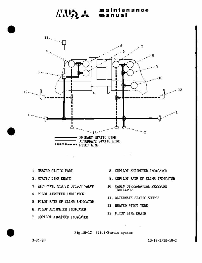
maintenancem a.n a a I
11
4
7
10
PRIMARY STATIC LINE
ALTERNATE STATIC LINE
PITOT LINE
1. HEATED STATIC PORT 8. COPILOT ALTIMETER INDICATOR
2. STATIC LINE DRAIPj 9. COPILOT RATE OF CLIMB INDICATOR
3. ALTERNATE STATIC SELECT VALVE 10. CABIN DIFFERENTIAL PRESSUREINDICATOR
4. PILOT AIRSPEED INDICATOR11. ALTERNATE STATIC SOURCE
5. PILOT RATE OF CLIMB IM3ICATOR12. HEATED PIT(Tr TUBE
6. PILOT ALTIMETER INDICATOR13. PIT(Tr LINE DRAIN
7. COPILOT AIRSPEED INDICATOR
Fig.lO-13 Pitot-Static system
3-31-90 10-19-1/10-19-2

maintenancemanual
j.P IE5T OF SZ4~IC PRESSL~J:a
(1) Disconnect static lines to cabin altitude differential pressure indi-
cator and airspeed indicator, and cap.
(2) Connect air source to static pressure air port and supply air
regulated to about 2.5 psi. Check air blowing off LH and RH static
pressure air ports and no blocking in the lines. After check, cover
the ports with tape.
(3) Remove caps for cabin altitude differential pressure indicator and
airspeed indicator, one afterthe other, and check air flowing out.
After check, cap again.
(4) Cap static pressure line of tester MB-1, apply 12,000 ft. ("1),13,800 ft. (*2) of negative pressure to tester and maintain for
one minute, then record indication (record leak for tester only).
(5) Connect tester to static pressure air port.
(6) One minute after applied pressure, the differential pressure
between indication after one minute and indicationrecorded per
Para. (4) shouldbe less than 20 ft.
(7) After completion of test, restore airplane to original condition.
3.3 OPERATIONAL CHECK OF STATIC PRESSURE LINE
(1) Check airspeed indicator, altimeter, rate-of-climb indicator and
cabin differential pressure indicator connecting to static pressurelines.
(2) Cover static pressure air port with tape.
(3) Cap static pressure line of tester ME-i, apply 12;000 ft. (*1),13,800 ft. (*2) of negative pressure to tester and maintain for
one minute, then record indication.
(4) Connect tester to drain port.
(5) Apply 12,000 ft. (*1), 13,800 ft. (*2) of negative pressure with
tester MB-1. At the same time, to the pitot connecting port of
airspeed indicator apply negative pressure lest the pointer should
deflect over the full scale. Check altitude indicator and cabin
differential pressure indicator indicating about 12,000 ft. ("1),13,800 ft. (*2).
(6) One minute after applied pressure, the differential pressure
between indicationafter one minute and indication recorded per
Para. (3) should be less than 240 ft. (*1), 276 ft. (n2).
*1 Aircraft S/N 652SA
*2 Aircraft S/N 661SA, 697SA and subsequent
10-20

IPi a i-n a a 8 a C ~e
in ~a si a a i
3.4 ’L~AK TES’I’ OF PITOT LIME
ii) Disconnect pitdt line to airspeed indicator and cap the line so
that pitot pressure will not be supplied to i6dicator.
(2) onn~ctair soulce to Pitot ti~be and supply air regulated to about
2.5
(3j Remove c~pand che~k that air flows out and tber~ is nB
itrline. After ~heck, cap again.
(4) Cap pitot line of tester MB-i, apply pressure~of .300 kt to pitotline and maintaii~ for one ininGte, then record indication (recordleak for festeronly).
(5) Disconnect air source froth pitot tube and connect tester MB-i.
(6) Apply pressure´• of 300 kt´•with tester and maintain for one minute.
One minute’later, Indication shbuld bethe value~recorded perPara. (4) plus´•or minus 1 kt;
.(7) After completionof test, restore airplane to originalcondition.
3.5´• OPERATTONAZ, CHECK OF PITOT LINE
(1) Make sure airspeed indicators connected to pitot tube.
(2) ´•Cap pitot line of´•tester MB-1 and applypressure of 300kt to pitotline,´•maintainfor one minute,then record indication.
(3) Connect tester MB-1 to pitot tube.
(4) Apply pressure.of 300 ktwithtester and make.’s~re airspeed indi-
cator indicates about 300 kt. Oneminute later, indication should
be the value-recorded per Para.´• (2) +0/-5 kts.
4. FLIGHT INSTRIFMENTS
4.1 ALTIMETER
The altimeteris a3 inch dial,~flange-mount typeinstrument, connected to
static pressure line, and ~indJcates pressure in terms of altitude corres-
ponding to atmospheric pr~ssure change dire to flight altitude change.
The instrumenthas 3.neediesi the’ long needle indicates hundreds of feet,middle needle thousands of feet andshortneedle ten´•thousands’bf feet.
Range of indication is.O to50,000 feet and atmospheric pressure.settingrange is 28.1 to 31;0’ inlHg. (851 fo 1,050 mb). The atmospheric pressure
setting is adjustable by turning a kno~ located in.one corner of- the in-
dicator.
When atmospheric’ pressure is Set´•.at sea level atmospheric pressure,
height from sea level iS:indicated. In order to know-height above a
certain airfield, set altimeter~at the airfield atmospheric pressure.When the needle-is ~et;:to 0, the pressure indiCation indicates atmos-
pheric pressureof that place.10-21

C~jSA in a i.ti a a n c 8iii a a a a)
4.1.1 TEST FOR SCALE ERROR AT ROOM TEMPERATURE
Test for scale error at room temperature is to be made at atmospheric
presstire approximately 29.92 in-Hg and at room temperature approximately770F (250C). Vibrationcondition of the test is at a frequency of
1500 to 2000 cpm and at amplitude of 0.002 to 0.005 in. The barometric
pressure scale shall be set at 29.92 in-Hg and the readingof the
pointers shall be taken. The error of this indication shall be
determined by comparison with a barometer. This error will be used
later in the after effect test. The reductib~ in pressure shall be
made at a rate not in excess of 20,000 ft. per minute in less than
about 2,000 ft. of the test point. The test point shall be approachedat a rate compatible with the test equipment. The altimeter shall be
kept at the pressure corresponding to each test pqint for at least
1 minute, but not more than 10 minutes before a reading is taken.
The error at all test points must not exceed the tolerances specifiedin the table.
A LTITUDE PRESSURE TOLERANCE
(feet) (in-Hg) f (feet)
-1, 000 31. 018 20
0 29.921 20
500 29.385 20
i, 000 28. 856 20
i, 500 2’8. 335 25
2,000 27.821 30
3, 000 26. 817 30
4, 000 25. 842 35
6,000 23.978 40
8,000 22.225 60
10,000 20.577 80
12,000 19.029 90
14, 000 17. 577 100
16,000 16.216 110
18,000 14.942 120
20, 000 13. 750 130
22,000 12.636 140
25,000 11.104 155
30, 000 8. 885 180
I~-oI10-22
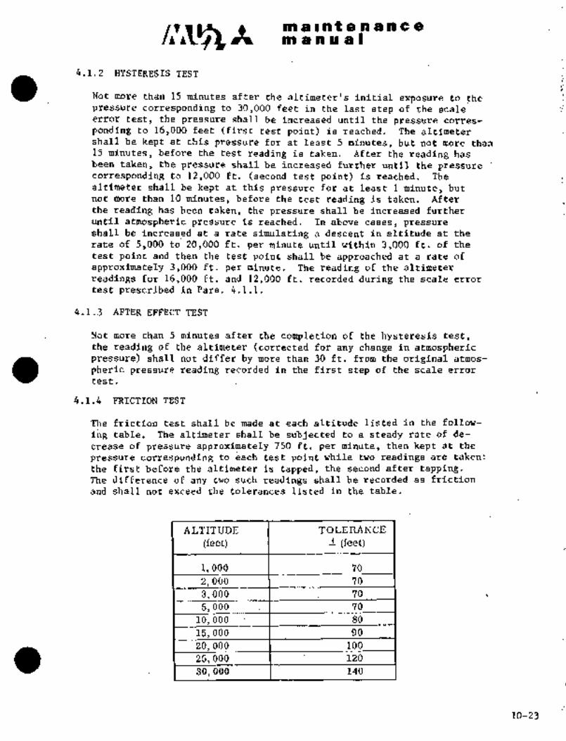
m a i~ at. a a ail a a
m a a ri a I
4.1.2 HYSTERESIS TEST
Not_more thanl5 minutes after thealtimeter’s initial exposure.to´•thepressure corresponding to 30,000 ~feet in the last st~ep of the scaleerror test, the pressureshall be increased until the pressure corres-
ponding to 16,000 feet (first test point) is reached. The altimetershall be´• kept at this pressure for at least 5 minutes, but not more than
15minutes, before the test reading i.staken. After the reading has
been taken, the pressureshall be increased further until the pressurecorresponding to12,000 ft. (second testpoint) is reached. The
altimeter shall be kept at this pressure for at leastl minute, but
not: more than 10 minutes, before the test reading is taken. After
the reading has been taken, the pressure shall be increased further
until atmospheric pressure is reached. In abovecases, pressureshall be increased at a rate simulating a descent in altitude at the
rate of 5,000 to 20,000 ft.´•per minute until within 3,000 ft. of the
test point and then the test point shall be approached at a rate of
approximately 3,000 ft. per minute. The reading of thealtimeter
readings for 16,000 ft. and 12,000 ft. recorded during the scale error
test prescribed in Para. 4.1.1.
4.1.3 AFTER EFFECT TEST
Not more than 5.minutes ~after .the completion of the hysteresis test,the reading of thealtimeter (correctedfor any change in atmosphericpressure) shall not differ by more than 30ft. from the original atmos-
pheric pressure reading recorded in the-first step of the scaleerrortest.4.1.4 FRICTION TEST
The friction test shall be made- at each altitude listed in the follow-
ing table. ’The altimeter shall be subjected to a steady rate of de-
crease of’pressure approximately 750 ft. per minute, then kept at the
pressure corresponding to each test point while Two readings are-taken:
the firstbefore the altimeter is tapped, thesecond after tapping.The difference bf any two such readings shall be recorded.as ´•friction
and shall not exceed the tolerances listed in the table.
ALTITUDE TOZIEItANCE
(feet) f (Eeet)
i, 000 76
2, 000 70.
3, 000 70
5,000 70
10,000-´• 80
15,’000 90
20,000 Ido
25, 000 1 120
30,000 140
10-23

C~g iti a I nP e n a ill c ain a n a a I
4.1.5 LEAK TEST
When the altimeter is kept to the pressure corresponding toan altitude
of 18,000 ft., the reading shall not change by more than 100 ft. within
one minute.
4.1.6 TEST FOR POSITION ERROR
With atmospheric pressure applied tothe altimeter, the difference
between the pointer indications in normal operating position and in
any other positionsshall not exceed 20 ft.
4.1.7 TEST FOR´•BAROMETRIC SCALE ERROR
At constant atmospheric pressure, the barometric pressure scale is set
at each of the pressures listed in the following table. The altimeter
shall indicate the equivalent altitude difference shown inthe table
with a tolerance of 25 ft.
PRESSURE ALTITUDE DIFFERENCE
(in-Hg) I (feet)
28. 10 i, 728
28. 50 i, 340
29. 00 863
29. 50 392
29.92 O
30. 50 531
30. 90 893
30. 99 1 974
4.2 AIRSPEED INDICATOR
The airspeed indicator is a 3 inch dial. flange-mounttype instrument.
Full pressure from.the pitot tube is led to the inside of a diaphragmcapsuleand static pressure from the static tube is ledto the outside
of the diaphragm capsule. The indicator indicates airspeed in knots bymeans of transmitting different pressure between inside and´• outside of the
diaphragm capsule to the pointer. Range of indication is 40 to 400 kts.
4.2.1 TEST FOR SCALE ERROR AT NORMAL ROOM TEMPERATURE
Test for scale error at normal room temperature is accomplished byapplying pressure corresponding to airspeed specified in the followingtable, to pitot connecting port of indicator, first with pressures
increasing, then with pressures decreasing. The errors should not
atmospheric pressure agproximately 29.92 in-Hg and at room temperature
exceed those specified in the table. The test is to be made at
approximately 770F (25 C).

iia s I i~ t ´•ce.ha ini e 8
tP1 P Db 119 dJ
SPEED ERRORS
~i(nots) (in-HzO) (Ki~ots)
50 1. 634 f4
60 2; 354
100 6. 5~3 f4
140 12. 94 f 10
iso 16. 95 fro
200 26. 71 f 10
250 42. 27 f 10
300 61. 82 f 10
350 85. 70 f 10
400 114. 33 f 10
4.2.2 INSPECTION FOR FRICTION
in the following table,l to pitot connecting port of the~ i~dicatqr.Inspectionfor’friction Is performed by applying pressure specified
The pressure should’ be’´•increased to bring the pointer approximatelyto the desired reading, and then held constant while two readings are
taken, thefirst before-the.indicator is tapped, the second after.
The difference betwe@n~ any two such readings should not exceed the
values’specifiedin thetable.´• The’ljointer should move smoothly while
thepressure is varieduniformly-without tapping.
SPEED I>nESSUnE ALLOWABLE ERROR
CKn´•ots) (iaHz O) (Knots)
50 i. 634 4. 8
100 6.563 4.8
160 16.95 4. 8
250 42.27 4. 8
350 85. 70 4. 8
4.2.3 INSPECTION FOR POINTER ZERO POSITION ~ERROR
When pitof connection ofindicato~ isopened to atmosphere, zero´•
position of the pointer shouldbe-~within 1/16in. ´•(1.6 mm).
10-25

c~smaintenancem anual
4.2.4 LEAK TEST
Pitot and static pressure connections of the indicator are jointedand connected together to sources of suction and pressure. A suc-
tion of 15 in-Hg is applied to pitot and static pressure connections.
With the source disconnected for 10 seconds, the pressure should not
change by more than 0.4 in-Hg. Then, the static connection is openedto the atmosphere and a pressure sufficient to produce approximatelya full scale deflection of the pointer is applied to the pitot con-
nection. During a period of 1 minute after disconnecting the pressure
source, the pointer should not change its position by more than 1 kt.
4.3 RPiTE-OF-CLIMB INDICATOR
The rate-of-climb indicator is a 3 inch dial, flange-mount type instrument.
It senses change of atmosphericpressure during climbing or descendingthrough static pressure lines and indicates change in terms of speed (ft/min)in vertical direction.. Range of indication is O to 6,000 ft/min.
4.3.1 TEST FOR SCALE ERROR AT ROOM TEMPERATURE
Test for scale error at room temperature is performed by giving a rate
of climb at each altitude interval specified in the following table.
Scale errors should not exceed the allowable value in the table. The
test should be conducted at atmospheric pressure approximately 29.92
in-Hg and at room temperature approximately 770F (250C).
When the test is made with atmospheric pressure or room temperature
differing materially from the above values, proper allowance should be
made for the difference fromthe specified condit-ion. Vibration condi-
tion of the test is at a frequency of.1500 to 2000 cpm and at amplitudeof 0.002 to 0.005 inch.
STD ALTITUDE TEST IZATE ALLOWABLE Ennon
~t) (~t /nl in) (ft;/m in)
2, 000 2, 500 500 100
2, 000 3, 000 1000 200
2, 000 4, 000 2000 300
2,000 5,000 3000 300
2,000 h 6, 000 4000 400
2,000 7,000 5000 500
15, 000 17, 000 2000 300
15, 000 17, 000 4000. 400
28, 000 30, 000 2000 300
28, 000 30, 000 4000 400
10-26
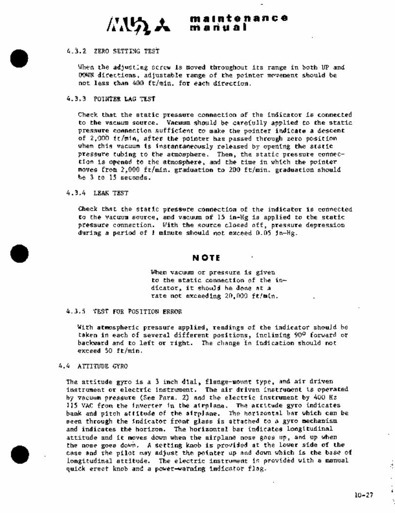
C~Aii~i ii ii iii;ii t ~i,.ii Y riii e
sir rr sri a a
4.3.2 Z~R6
When the adjusting sdre~i is moved thrd~ghbut its range in bbth UP and
DOWN directiolis, adjustable range of~the pointer movement should be
not less than 400 ft/miii. for each difection.
4.3.3 POI~TER LAG TEST
Check that the staticpressure connectionof the indicator is connected
t~ the vacuum sour~e. Vacuum should be caref~lly applied to the static
press~re connection sufficient to make the pointer indicate a descent
of 2j00b ft/min, afte~the pointer has passed through zero positionthis vacuum is instantaneously released by opening the static
pressure ti~bing to the atmosphere. Then, the static pressure connec-
tioli is opened to the atmosphere, and the time in which the pointermoves from 2,000 ft/min. graduation to 200 ft/min. graduation should
be 3 to 15 seconds.
4.3.4 LEAK TEST
Check that the statiC pressure connection of the indicator is connected
to the vacuum source, and vacuum of 15 in-Hg isapplied to the static
pressure connection. With the source closed off, pressuredepressionduring a period of 1 minute should not exceed 0.05 in-Hg.
N OTE
When vacuum or pressure is givento the static connection of the in-
dicator, it should be doneat a
rate not exceeding 20,000 ft/min.
4.3.5. TEST FOR POSITION ERROR
With atmospheric pressureapplied, readings of the indicator should be
taken in´•each of several different positions, in‘clining 900 forward or
backward and to left or right. The change in indication should not
exceed 50 ft/min.
4.4 ATTITUDE GYRO
The attitude gyro is a 3 inch dia~,´•flange-mount type, and air driven
instrument or electric instrument. ~The airdriven instrument is operatedby vacuum pressure See Fara. 2) andthe electric instrument by 400 Hz
115 VAC from:the inverter-in the.airplane. The attitude gyro indicates
bank and pitch attitude of the airplane., The horizontal barwhich can be
seen through ´•the indicator is attached to a gyro‘mechanismand’ indicates the horizo;i. ’The‘:horizontal bar.indicates longittidinalattitude and it moves down´•when ´•the airplane nose goes ´•up,:and-- up when
the nose goes~.down. A setting.knob is providedat the lower side of the
case and the pilot may adjust the pointer up and down which is´•the baseof
longitudinal attitudC. Th‘e electric instrument is provided with a manual
quick erect knob:and apower-warning indicator flag.
10-27

c~ It .ni a t at Ct a a a a a
epn a a a a I
4.5 TZlRN BANK INDICATOR
The turn and bank indicator is a 3 inch dial flange-mount type iristrument
which incorporates a turn indicating pointer actuated by electrical gyro
powered by 28 VDC and a bank indicator which contains damping fluid and
black ball in a glass tube. ~he turn indicating pointer is calibrated to
a two minute turn. The indicator is installed so that pointer may be
placed in vertical position with aircraft in level attitude.
4.6 CLOCK
The clock is a 2 inch dial, flange-mount type instrument which permits
reading seconds. This is an 8-day spring-wound clock.
4.7 MAGNETIC COMPASS
The magnetic compass is installed in the center of the windshield center
post and indicates magnetic heading of the airplane. Compensation of
indication is possible by means of a compensator contained in the compass.Indication errors are recorded on the compass card located immediatelyabove the instrument. An illuminating light on 28 VDC power source is
installed inside. The magneticcompass must be calibrated usually everythree months.
4.7.1 CALIBRATION OF MAGNETIC COMPASS
Compensate the magnetic compass on the ground in accordance with the
following procedures.
(1) Place aircraft on compass rose, ready to be oriented to magneticheading.
NOTE
Do not place any magneticmasses near aircraft.
(2) Check compensator of magnetic compass for emplacement in neutral
position. If compensator is not placed in neutral position,replace it~in proper position.
(3) Head the aircraft to magnetic~, note compass reading and
determine deviation.
(4) Turn aircraft to W, N, and E in succession and repeat proceduresin Para. (3) above.
(5) Calculate coefficients C, B and A from deviation 6f slaving meter
obtained at every heading of aircraft.
10-28
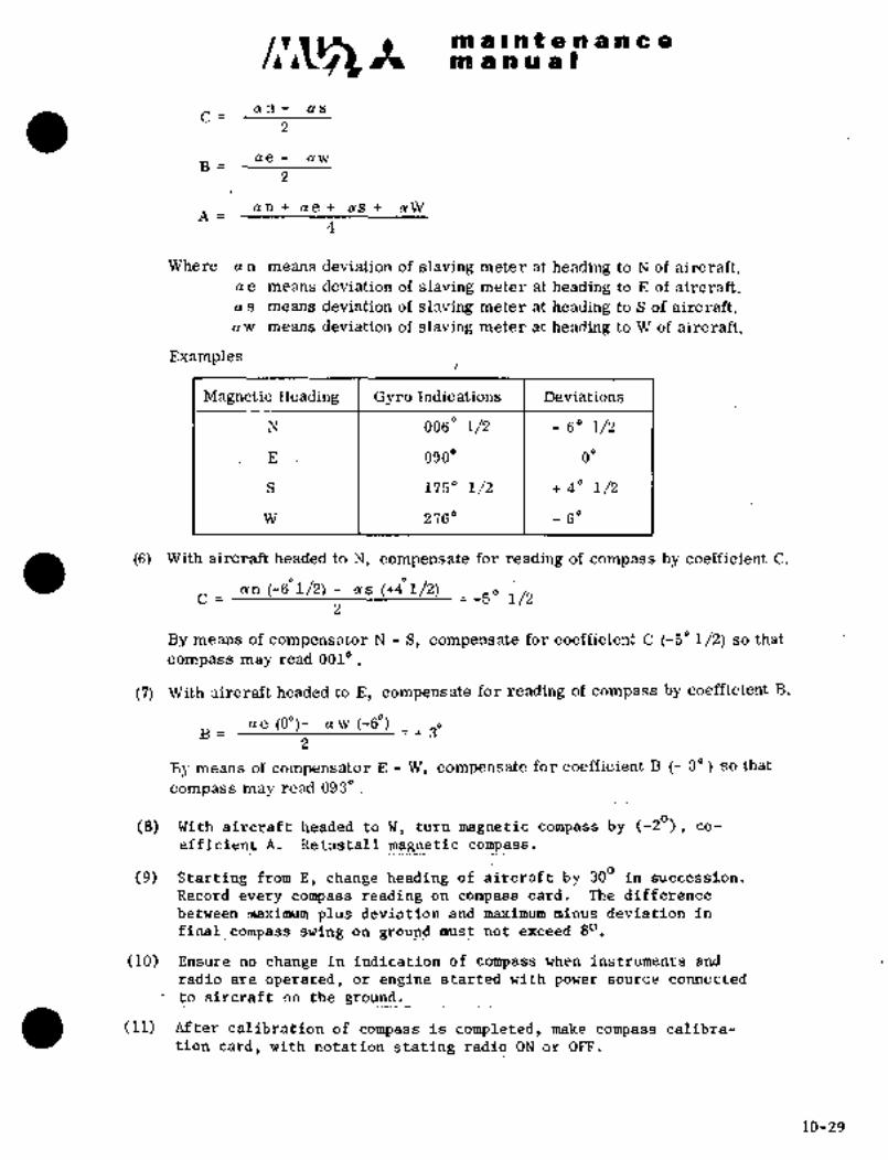
c~s 8P Il~ifBnsnceatlj 8 n U a s
an- as
ae L aw
an ae as aW
Where a n means deviation of slaving meter at heading to N of aircraft.ae means deviation of slaving meter at heading to E of aircraft.
a s means deviation of slaving meter at heading to S of aircraft.
aW means deviation of slaving meter at heading to W of aircraft.
Examples
Magnetic Heading GySo indications Deviations
N 0060 1/2 60 1/2
E 090" 0"
S 1750 1/2 t- 40 1/2
W 2760 60
(6) With aircraft headed to N, compensate for reading of compass by coefficient C.
an (-601/2) as (+41/2)C -5" 1/2
By means of compensator N S, cmpensatefdr coefficient C (-5"1/2) so that
compass may read 0010
(7) With aircraft headed´•to E, compensate for reading of compass by coefficient B.
ae to")- _(vw (-6")i 30B=
By:means of compensator E: W1~ compensate for coefficient B 3") so that
compass may read 093"
(8) With aircraftheaded toW, turn magnetic compass by (-2"), co-
efficient A. Reinsfal~ magnetic compass.
(9) Starting from E, change heading of aircraft by 300 in succession.
Record every compass r~ading:oncompass card. The difference
between maximum plusdeviatlon and maximumminus deviation.in
final_compass ~swing on gFoU´•~ must not exceeds"
(10) Ensure no change in indidation-of compass when instruments and
radio are operated, or engine started with power source connected
to aircraft on the ground.
(11) After cal-ibratibn:ldf compass: is: completed,’make ~compass calibra-
tion~card-, with notation stating radio ON oir.OFF.
10-29
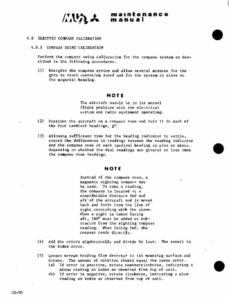
Im a In t a a a a a a
pn a a a a I
4.8 EI~ECTRIC COMPASS CALIBRATION
4.8.1 COMPASS SWING CALIBRATION
Perform the compass swing calibration for the compass system as des-
cribed in the following procedures.
(1) Energize the compass system and allow several minutes for the
gyro to reach operating speed and for the system to slave to
the magnetic heading.
NOTE
The aircraft should be in its normal
flight positionwiththe electrical
system and radio equipment operating.
(2) Position the aircraft on a compass ~rose and turn it to each of
the four cardinal headings, fO.
(3) Allowing sufficient time for the heading indicator to settle,record the differences in readings between the heading indicator
depending on whether the dial readings are greater or less than
and the compass rose at eachcardinal heading as plus or minus,
the comi~ass rose readings.
NOTE
Instead of the compass rose, a
magnetic sighting compass maybe used. To take a reading,the compass is located at a
considerable distance fwd and
aft of the aircraft and is moved
back and forth from the line of
sight coinciding with the plane.When a sight is taken facingaft, 1800 must be added or sub-
tracted from the sighting.compassreading. When facing fwd, the
compass reads directly.
(4) Add the errors algebraically and divide by four. The result is
the index error.
(5) Loosen screws holding´• flux detector to its mounting surface ai~d
rotate. The amount of rotation should equal the index error.
(a) If error is positive, rotate counterclockwise, indicating a
minus reading on index as observed from top of unit.
(b) If error isnegative, rotate clockwise, indicating a plusreading on index as observed from top of unit.
10-30

c~a ni a I‘~h f ’ri ai n a a
m a a a a I
(6) Tighten the’moimtirig scr~ews and recheck the readii~gs at the four
Recalculate the i~dei error to make sure it
ii~ zero.
(7) IT the in~eX ~rror is riot iero, rPadjust the iilux di~tector fian~eimti~ this error is ca$celled.
(’8) Aiiy errors in excess oE.~ 10 which are caused by extra-
iieous magnetii~ fields should be ~buriteracted by using the~coinpen-sator (i~ installed).
4.8.2 ADJUST ~RC-1 TO COMPENSATE FOR SINGLE-CYCL~ ERRORS (HARD IRON: EFFECTS)AS~DESCRIBED IN THE FOLLOWING PROCEDURES.
(1) Remove the DRC-1 cover.
(2) Make sure compensation potent~ometers, are in their center position.
(3) ´•Using a compassrose, placethe:aircraft on.a North heading 10a~d allow compass dial or Radio Deviation: Indicator (RDI)´• to-settle.
(4) Compensate for any difference between actual heading and RDI
indication by loosening the rocking nut and adjusting N S
(North-South) potentiometer on DRC-1 (tighten locking nut).
(5) Place~the aircraft~on an.East’heading 10and allowthe compassdial to settle.
(6) Compensate for any difference between actual headirig and RDI
indication by loosening lock nut and adjusting E W (East-West)potentidrmeter on DRC-1 (tightenloclring nut).
(7) Place the aircraft on a South heading f 10 and allow compass
dial to settle.
(8) Compensate for half of any.difference betweenactual heading and
RDI indication by loosening locking nut and adjusting N S poten-tiometer on DRC-1 -(tighten locking nut.
(9) Place the aircraft on a West heading f 10 and allow compass
dial tosettle.
(10) Compensate for half of any differen~e between actual heading and
RDI indication byloosening locking nut and adjusting E W pdten-tiometer (tighten’occking nut).
(11) The DRC-1 should now be fully adjusted for proper compensation.Asa´•check, swing.the~:aircraft o~ 300 increments and note readingson comp;ass dial´•~’All readings should be within floo~f theactual
heading. If errors are greater than f lo, repeat index error ad-
justment of paragraph 15.1 and the above adjustments for greater
accuracy.
4.8.3 CONFIRMATION
Stop the aircraft at taxiways parallel to and at a right angle to´•
the runway~ ahd confirm the Compass indications. The compasses should
not be split by more than~ 20.a; any’ point.10-31

maintenancemanua9
4.9 AILERON-TRIM POSITION INDICATOR (Fig. 10-14)
The aileron-trim position indicator is installed on the lower center
section of the center pedestal and is an ammeter which’works in a bridgecircuit consisting of a transmitter and adjusting resistance installed on
the forward back side of the center pedestal. The electric power source
is 28 VDC. When indicator or transmitter has been replaced, adjustmentshould be accomplished in accordance with Para. 8.4.3, Chapter V.
Pig. 10-14 Aileron-trim
position ind.
ORIGINAL
As Received ByAT P
10-32

pn Ilnit e ~nncte
4.10 ’rROUBLE SHdOTING
4.10.1 II~TIMETER; AIRSPEED INDICATOR INDICATOR
Trouble Pr´•obable cause I’ie 117 e’tlv
Instrument inai- a, Stdtic pressure line Drain static pressure
cation is inaccui~ate, is blocked, I line and clejn line.
instrument does not
u´•ork dr needle I I~ALiTiONfluctuates
Instruments.must be dis-
c~nnected before apply-´•ing air to clean lines.
b, Static p´•ressure line I Perform leak test and
i leaking, I repair defective com-
p~nent.
c, Instrument defective, Replace instrument.
Rate of climb indi- I a, Calibration of instru- Turn adj Listing screw
cater does not I ment is I located on L.H. lower
indicate zero in I I section of instrument.
level:flight, Give a little.vibration
to instrument during
adjustment.
Air speed’indicatbr la. Pitot line is blocked. Drain static pressure
indic~tion is in- I I line and clean,
accurate, instru-
ment does not urork CAUTION
or needle flactuatesNever use air to clean
lines without disconnect-
ing lines froni.instru-
ments,
b, Pitot. line is leaking. I qerform leak test and
repair ´•defective compo-
nent.
c, -Tnstrument faulty. I ’Replace instrument.
10-33
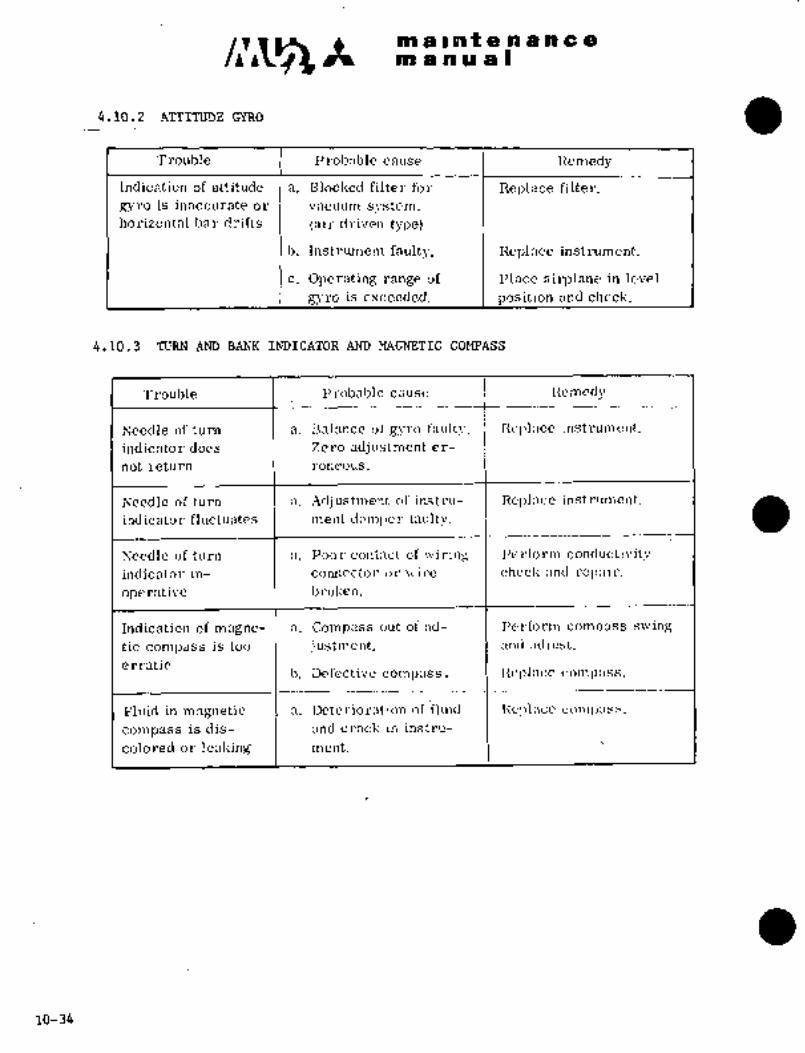
m a I at a a a a -e a
manual
4.10.2 ATTITUDE GiRO
Trouble Probable cause Itemedy
Indication of attitude a. Blocked filter for neplace fi.lter.
gyro is inaccurate or vacuum system.horizontal bar drifts lair driven type)
b. Instrument; faulty. Replace instrument.
c; Operating range of Place airplane in level
gyro is exceeded. position and check.
4.10.3 TURN AND BANK INDICATOR AM) MAGNETIC COMPASS
Trouble Probable cause Remedy
Needle of turn a. I3alance of gyro fault!´•. Replitce, instrument.
indicator does Zero adj ustment er-
not return roneous.
Needle of turn a. Adjustn~ent of instru- Replnce instrument.
indicator fluctuates ment dnmi,er faulty.
Needle of turn a. Poor cont;zct of wiring Pe~form conductivity
indicator in- connector or wj I.-e checl; anti rep;~i r.
operative b~oken.
Indication of magne- a. Compass out of ad- I>el´•form compass swing
tic compass is too justment. and ;~cljust.
erraticb. Defective compass. Replace comp:iss.
Fluid in magnetic a. Deterioration of fluid ncpl:ice colnl,ass.
compass is dis- and crack in instru-
colored or leaking ment.
10-34

c~s pn a ilt a a a a a
m a a a a)
RTEL QUANTTTYINDICATOR
5.1 DESCRIP~ION
Capacitor type fuel quantity ’imlicators. are pi´•oviaed. With several
cylindrical tank units dipped in fuel, a change in fuel level.and
specific weight of fuel are indicated as compensated by electrical
capacity on the basis of different rates of induction of fuel and air.
Fuel quantity indicators~include wing tank´•fuel quantity indicator and
tip tank fuel quantity in~icator.
5.2´• WING TANK FUEL QUANTITY INDICATOR
Thewing tankfuelquantity indicator systemconsists of a 2 inch dial
clamp mount type instrument installed on~thecenter switch panel,capacitor type tank units, each one in the center tank, LH and RH outer
tanks and a test switch‘ for operational check on.the center switch panel.Capacitor indication isgiven in.terms of GAL. When residual fuel is
decreased until it is sufficient only for 30 minutes flight (30 f 5 gal.),FUEL LOW LEVEL warning ’light illuminates. The amplifier contained in the
fuel quantity indicator converts an input~signal from the tank unitinto
U.S. gallons. The fuel quantity indicator system receives power supplyof 115VAC 400 Hz from the inverter. The electrical capacity of the tank
unit is compared with that of a reference condenser in re-balancing the
type bridge- circuit through the medium of change in fuel level ~or quantity
amplifier, energizes’the transistor of the phase.discriminator output.Anunbalancing signal, amplified by a transistor voltagein the tank.
The output voltage is transmitted to one of the 2 phase AC motors, and
mechanically actuates the rebalancing potentiometer and needle of the
fuel quanfity indicator. For theother phase of the AC motor, power of
115 VAC is transformed to´• 15 V by a.transformer contained in the
indicator-and a rectified convertible two-phase induction motor-driven
sliding part of the balance´•´• potentiometer, through the medium of a gearmechanism of alargC reduction ratio, and.keeps the bridge circuit
balanced; A pointer attached on the, same axis as that of the sliding´•part indicates fuel quantity in U.S. gallons. Components of the fuel
quantity indicator are contained. in a sealed case. Electrical connections
are provid~d at the back of the instrument to set‘ the indicator of the
elec~rical’capacity of the tank unit with fuel EMPTY and mnL.
5.3 TIP TANK FUEL QUANT´•ITY. INDICATOR
The tip tank fuel quantity indicator system consists of: a 2-inch dual
clamp mount; dual pointer tyPe instrumenf installed on the center switch
panel; one each..capacitbr type´• tankun´•i´•ts’id the -LH: and RH tip tanks; an
amplifier at the back of left´•´•instrument panel; and a test switch for
operational check on the RH switch~ panel. Fuel quantities in both tiptanks are indicated by pointers marked L and Ri respectively. Indication
is given in terms of GAL. The amplifier contained in the’ fuel quantityindicator converts an input signal from the tank uni´•t into U;S. gallons.Electricalcapacity of the tank unit is compared with that of reference
condenser ir?.a re-balancing type bridge circuit’ through the medium of
change´• in fuel level or quantity in the tank. The unbalancing signal,amplified by a transistdr voltage amplifier, energizes the transistor of
10-35

pna a81na e a d pr a a
rril a si ii a
the phase discriminator output. The output:voltage is transmitted to
one of the 2-phase AC motors, and mechanically actuates the re-balancingpotentiometer and needle of the fuel quantity indicator. For the other
phase the AC niotor, poeer of 115 VAC 400 Hz, is transformed to ´•15 V by a
transformer contained in the indicator and rectified. Two pointers (L over
R) are attached on the same axis of the dial. Each pointer is connected
’to a balancing potentiometer and convertible two-phase induction motor
through the medium of gear mechanism of a large reduction ratio. Elec-
trical connections are provided at a receptacle at the back of the
instrument.
5.4 AMPLIFIER
The amplifier is provided at F.STA 1250 at the back of the LH switch panel.The amplifier consists of individual amplifiers for LH and RH tip tanks,bridge circuits and regulating screws. Incorporated in each assemblyare amplifying circuits with phase discriminating function, transformer
and reference condenser for the bridge circuit, EMPTY and FULL regulator,potentiometer and phase power source for´•the indicator motor. An elec-
trical connection is provided at the receptacle located on one side of the
container. On the other side of the container, a regulating screw is
provided.
5.5 CENTER TANK UNIT
The tank unit consists of 2 concentric electric’poles. The poles are
insulated by a plastic spacer interfaced for the entire length of the
poles. The induction ratio between 2 poles of the tank unit changes,depending upon fuel level in the tank. The tank unit is clamped to the
inner wall by 4 bolts. On top of the unit, 4 connectors are provided.
5.6 OUTER TANK UNITS
The outer tank units are the same as the center tank unit in construc-
tion, function and installation, but smaller in length.
5.7 TIP TANK UNITS
Tip tank units are the same as the center tank unit ´•in construction,
function and install8tion. On top of the units, 2 connectors are pro-
vided.
5.8 TEST OF INDICATOR
5.8.1 WING TANK FUEL QUANTITY INDICATOR
(1) Connect the indicator as shown´•in Fig. 10-15, select the
condenser.capacity per the following table, and read
the
(2) When indicator reads :30 5 gallons, check pointer deflection.
10-36

C~S k rrlaa n O g=
BIW ti IH U 8
AC power s~odrde
s.w
D 1TesterFuel qt3’ )E
indica~tdfl8’ _I
CrI
~Test SW
Pig. 10-15 Wing tank fuel qty. ind.
Static i~lectric CapacityZndicator Reading (GAL) I of CX (PF)
E (O) 1 129.3
20 1. 143. 0
60 178, 3
90 1 204. 7
120 1 231. 1
150 1 257. 5
F (154) 1 260. 5
10-37

ill alat a a a a a a
m a a a a II
5.8.2 TIP TANK FUEL QUANTITY INDICATOR
Connect the indicator as shown in Fig. l0-16,~select the condensercapacity per the following table, and read the indicator.
Cr\
Fuel qtyD I’
indicator c n Amplifiern w
E x
L
ri :I
J 1´•
u~ u
t Y
M z
N r,
N
R M
I Fi
Test SW F
C;P Y
Fig. 10-16 Tip tank fuel qty. ind.
indicator neading (GAL) Static El:ectric Capacity (PF)
Cxl(ni~ht) I Cx2 Left-
E (O) 55. 0 5. 0
15~ 64. 4 1 64. 4
30 73.8 1 73. 8
45 83. 3 83. 3
60 1 92. 7 92.. 7
75 1 102. 1 1´• 102. 1
F (90) 111. 5 1 111. 5
10-38

6~ Ar: ~;oi ii la~ Ilk ejr iEa E e
tsia ri R ih iP ´•s
5.9 ADJUST~ENT bF MA~N TA~ Fi~EL 9UANTITY INI)ICATING SYSTEM
~iT ’’E~P;’jrY" PO~NT
(1) Letel the airplane and drain thrdugh drain iralve to keepthe tank unit dry. (Undrainable fuel 1.0 U.S. gallons remains
in the tank.)
(2) Supply fuel 4.0 U.S. gallons into the fuel tank.
(3) Turn Battery Key swit~h, circuit breaker (FUEL QTY IND)~andinirerter swlt~h to ON;
(4) AScelifain that quai~tity indi~cator indicates "E" point under
the above condition. If he indicator does not show "E" point,adjust. by the:"E" adjusting screw on the back of the indicator
so that the indicator map read "E" point.
5.9.2 ADJUSTMENT AT "F~LL" POINT
(1) Fill up the tank after completing adjustment at "E" point.
(2) Ascertain that ~uel quantity indicator indicates "F" point when
the tank is filled up. If the indicator does not show:"F" point,adjust by the (’F" adjusting screwon the back of the indicator
so that the indicator may read "F" point.
5.10 ADJUSTMENT OF TIP TANK FUEL QUANTITY INDICATING SYSTEM~
5.10.1 ADJUSTMENT AT "EMPTY" POINT
(1) Level the airplane and drain fuel through drain valve to keepthe tank unit dry.
(2) Turn Battery Key switch, circuit breaker ~TIP FUEL QTY IND) and
inverter switch to ON.
(3) Ascertain thatfuel quantity indicator indicates "E" point.If the indicator does not show "E" point, adjust by the "E"
adjusting screw onthe´•side of the amplifier so that~the indi-
cator may read "E" point.
5.10.2 ADJUSTMENT AT "FULL" POINT
(1) Fill up the tank after completing~adjustment at ’’E":point.
(2) Ascerrain that indicator indicates "F" point when
the tank is filled:up.. If the ´•indicator does not show."F" point,adjust by the"F" adjustingscrew on theside.of the amplifierso~that the indicator may read "Flpoint.
10-39

~n a i n t e.n a n a
sil a ii ii is I
j.ii OPERATION~ CHECK OF FUEL Q~JANTITP INDICATdR
Operational che~k of the fuel quantity indicators should be performedfollowing the adjustment of the "F" point indication, To test the fuel
quantity indicators, place the FUEL Qm TEST switch to the MAIN positionand confirm the main fuel quantity indi~ator needle moves smoothly toward
EMPTY (zero) direction. Place the test-switch to the TIP position andconfirm the tip fuel qitant~itl indicator needles move smoothly toward
EMPTY (zero) direction.
5.12 CHECK OF LOW LEVEL WARNING LIGHT
Ascertain that the warning light "FUEL LOW LEVEL" on the annunciator
panel illuminates when the fuel quantity indicator indicates 30 5 gallonswhilein check per Para. 5.11.
5.13 TROUBLE SHOOTING
Trouble Probable cause Remedy
Indication 05 fuel a. Systemadjustment Readjust system.
quantity indicator faulty.is inaccurate
b. Tank unit defective. Check tank unit.
c. Indicator faulty. Replace indicator.
Needle of indicator a. Friction error of Replace indicator.
is stuck indicator excessive.
Needle of indicator a. Faulty:Amplifier. Check and.repairfluctuates during amplifier.flight
10-40
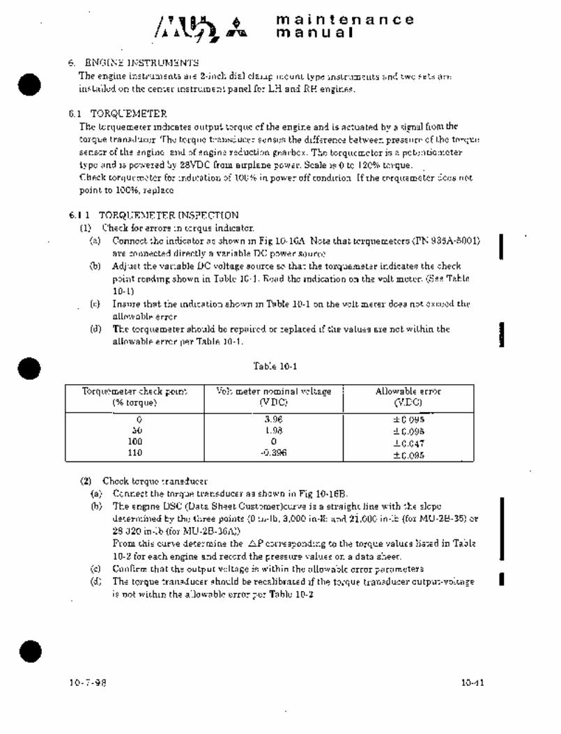
na a i nit a n a n c a
~4 manual
6. ENGINEINSTRUMENTS
The engine instruments are 8-inch dial clamp mount~ type instruments and two sets -are
installed on the center instrument panel for LH and RK engines.
6.1 TOR&UEMETERThe torquemeter indicates output torque of the engine and is actuated by a si_rmal from the
torque transducer. The torque transducer sens~s the difference between pressure of the torque
sensor of the engine, and of engine reduction gearbox. The torquemeter is a potentiometertype and is powered by 28VDC from airplane power. Scale is O to 120% torque.Check torquemeter for indication of 100% in power off condition. If the torquemeter does not
point to 100%, replace.
6.1.1 TORQUEMETER INSPECTION
(1) Check for errors in torque indicator.
(a) Connect the indicator as shown in Fig 10-16A. Note that torquemeters (PN 935A-5001) Iare connected directly a variable DC power source.
(b) Adjust the variable DC voltage source so that the torquemeter indicates the check
point reading shown in Table 10-1. Read the indication on the volt meter. (See Table
10-1) i
(c) Insure that the indication shown in Table 10-1 on the volt meter does not exceed the
allowable error.
(d) The torquemeter should be repaired or replaced if the values are not within the Iallowable error per Table 10-1.
Table 10-1
Torquemeter check point Volt meter nominal voltage Allowable error
torque) Cv.DC) Cv.Dc)
0 3.96 f0.095
50 1.98 +-0.095
100 0 -t0.047110 -0.396 10.095
(2) Check torque transducer
(a) Connect the torque transducer as shown in Fig 10-16B.
(b) The engine DSC (Data Sheet Customer)curve is a straight line with the slopedetermined by the three points (O in-lb, 3,000 in-lb and 21,000 in-lb (for MV-2B-35) or
28,320 in-lb (for MU12B-36A));From this curve determine the aP corresponding to the torque values listed in Table
10-2 for each engine and record the pressure values on a data sheet.
(c) Confirm that the output voltage is within the allowable error parameters.
(d) The torque transducer should be recalibrated if the torque transducer output-vaitage Iis not within the allowaljle error per Table 10-2.
10-7-98 10-41

maintemancema a n La a I
Table 10-2
For MU-2~-35
Torque load inch/pounds Torquenp transducer
error
(psid) output-voltagein-lb (V.DC)
(VDC)
0 0.0 3.960 +0.1
3,000 14.3 3.394 f0.1
21,000 100.0 0.00 +0.03
For MU-2B-36A
Torque load inch/pounds ´•Torque AllowablenP transducer
error
(psid) output-voltageIn-lb (vnc)
(V.DC)
0 0.0 3.960 f0.1
3,000 10.6 3.541 +0.1
28,320 100.0 0.00 rt0.03
(3) Torque transducer calibration
I For PIN 895369-1. -2. and 3101299-1
(a) Connect the torque transducer as shown in Fig 10-16B.
I (b) Set nP corresponding to 21,000 in-lb (for MU-2B-35) or 28,320 in-lb (for MU-2B-36A)
by adjusting the pressure source.
I o Loosen the zero adjust lock screw on the front of the transducer. Using a spanner wrench
in the two holes on the face, rotate the inner body of the torque transducer until 0.00+
O.OSVDC output is observed. (Re~Eer to Fig 10-16C)
NOTE
Clockwise rotation increases positive voltage.
(d) Set nP corresponding to 3,000 in-lb by adjusting the pressure source.
ie) Remove dust cover from span adjustment screw. Rotate span adjustment screw until
an output voltage versus torque is observed as 3.394+ O.lvolts (for MU-2B-35),
3.541f O.lvolts (for MU-2B-36A) on the volt meter. (Refer to Fig 10-16C)
NOTE
Clockwise rotation increases positive voltage.
(f) Increase pressure of the pressure source to 100% torque and verify that a O.OO-f
0.03VDC output is observed. A recheck of steps (b) to (e) may be required.
(g) Obtain nP output voltage corresponding to the torque listed in Table 10-2.
By varying pressure of the pressure soiirce, confirm that the output voltage is within
the values described in Table 10-2.
10-41-1 10-7-98

IIPa a i n t a re a P1Ce
I~P a n u a.l
01) Upon completion of the adjustment, install. the span adjustment dust cover finger tight.
Tighten zero adjustment lock screw to 10-15 in-lbs and lockwire the cover to the zero
adjustment lock screw. Apply sealant.
(i) Recheck the setting of torque transducer.
Cj) Reinstall torquemeters and torque transducers in the airplane making sure that the
proper transducer is mated to its matched engine.
0 For P/N 897331-4/-5
(a) Connect the torque transducer as shown in Figure 10-16B.
(b) Set nP corresponding to 21,000 in-lb ´•(for MU-2B-35) or 28,320 in-lb (for MU-2B-36A)
by adjusting the pressure source.
(c) Remove the adjustment plug with a 3/16 inch Alien wrench to provide access to the
span and zero adjustment screws. Rotate the zero screw (marked "Z" until O.OOt
0.03VDC output observed. (Refer to Figure 10-16C)
’N O T E
Counterclockwise rotation increases positive voltage.
(d) Set nP corresponding to 3,000 in-lb by adjusting the pressure source.
(e) Rotate range adjust screw until an output voltage versus torque is observed as 3.394
rt O.lvolts (for MU-2B-35) or 3.541+ O.lvolts (for MU-2B-36A) on the volt meter. (Refer
to Figure 10-16C)
NOTE
Counterclo6kwise rotation increases positive voltage.
Switch D.C variable/
Torquemeterpower source
Voltm eter
Fig 10-16A Test setup for torquemeter inspection I10-7-98 10-41-2

maintenancemanual
(f) Increase pressure of the pressure source to 100% torque and verify that a 0.00+
0.03VDC output is observed. A recheck of steps (b) to (e) may be recluired.
(g) Obtain nP output voltage corresponding to the torque listed in Table 10-2.
By varying pressure on the pressure source, confirm that the output voltage with the
values described in Table 10-2.
01) Replace adjustment plug. Safety wire, as appropriate.
(i) Recheck th~ setting of torque transducer.
Cj) Reinstall torcluemeters and torque transducers in the airplane making sure that the
proper transducer is mated to its matched engine.
6.1.2 Ground Check
With the torque transducers and torcluemeters installed in the airplane conduct a ground run
to verify that full power can be set and the engines are essentially symmetric.
(a) Start engines and verify no leakage from the torque transducers.
(b) Check engine output torque for the ambient pressure altitude and temperature with
the Power Assurance Chart in the Performance Section of the Airplane Flight Manual.
(c) Record torque, RPM, EGT, and Fuel Flow for both engines at the takeoff power
obtained from the AFM power assurance chart for the ambient conditions.
(d) Record the engine parameters at the ground idle setting.
(e) If the power assurance torque check is successful and the other engine parameters are
reasonable, proceed to the next step. If the torque cannot be attained, and the reason
for the low torque indication cannot be determined, the engine may have internal
damage and require additional maintenance inspections before takeoff is attempted.
10-41-3 10-7-98
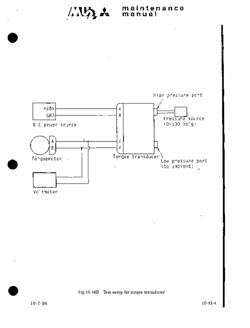
ap´•n a i n t a TP a BP Ga
pa~8 a n u a I
High pres~sure port
+28V’ ’A
GNDI IBPressure source
D.C power source (0-100 psig)
Al ’C
B1 ’F
Torquemeter I I Torque transducerLow pressure port(to ambient)
Voltmeter
Fig 10-16B’ Test setup for torque transducer
10-7-98 10-41-4

It sn a i n t an a n ce
ra a nual
From engine torquepressure port
Unit under test FrontFrom engine gearcase (Transducer) o
negative case
pressure port
To 28V DC source To 28V DC source
Dust cover
F
Zero adjust
F\\
Span adjust screw
lock screw
A AEo Eo
B B~oo Do
C C
Spannerwrench Access plug for zeroholes and span adjustment
(Range)Front view Front view
(P/N 895369 and P/N 3101299) (P/N 897331)
Fig 10-16C Location of adjustment on torque transducer
10-41-5 10-7-98
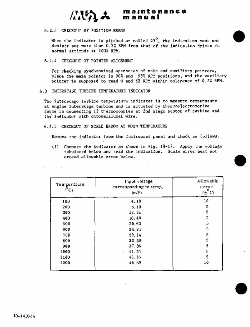
/P~C Ict it8 i6i~ I: ~9 h 6I C 8
PtI b~ OP ill a I
6.2,3 CHECI~OUT OF ERROR
When the indicatoir is pitched or rolled 450, the indication must ndt
deviate any more than 0.3% RPM from that of the iindication driven in
normal attitude at 1002 RPM.
6.2.4 CHECKOUT OF POINTER ALIGNMENT
For checking synchronized operation of main arid auxiliary ~oinTers,place the pointer in 90% and 96% RPM positions, and the auxiliarypointer is supposed to read O and 6% RPM within tolerance of d.2% RPM.
6.3 INTERSTAGE TURBINE TEMPERATURE INDICATOR
The interstage turbine temperature indicat6r is to measure temperature
at engine interstage turbine and is actuated by thermoelectromotive
force in connecting 12 thermocouples at: 2nd stage stater of turbine and
the indicator with chromelalumel wire.
6.3.1 CHECKOUT OF SCALE ERROR AT ROOM TEMPERATURE
Remove the indicator from the instrument panel and´•check as follows.
(1) Connect the indicator as shown inFig. 10-17. .Apply the voltagetabulated below and read the indication. Scale error must not
exceed allowable error berow.
Input voltage Allowable
Temperature corresponding to temp. error
C)(mV) c~c,
100 4. 10 10
200 8. 13 5
300 12. 21 5
400 16.-40 5
500 20.65 5
600 24.91 5
700 29. 14 5
800 33. 30 5
900 37. 36 5
1000 41;’31 5
1100 45. 16 5
1200 48.89 10
10-(43)44

n~ a In t a a a a a a
m anual
Indicator
FED CBAalumel wire
copper VariableGNDwire
power
copper corres-
("1) 115 VAC 400 Hz unit(mV)
("2) 28 VDC
wire pendingchromel wire
each temp.Ice box
Pig. 10-17
6.4 OIL PRESSURE INDICATOR
This system indicates pressure of lubricating oil. This instrument, a
dual needle read-out, is a voltage ratio type instrument and is poweredby 26 VAC 400 Hz power from the ircraft inverter. The indication range
is O to 200 psi.
6.5 OIL TEMPERATURE INDICATOR (See Pig. 10-18)
This system indicates temperature of the lubricating oil and its sensor
is attached to the reduction gearhousing of the engine to a torqueof 60 to 65 in-lbs. (69 to 74.~ kg/cm). The indicator is ioperated by the
change in resistance in response~ to temperature change and is powered by28 VDC. Range of indication is -70 to -f-1500C (-94 to +3020F).
ORIGINALAs Received By
AT P
Big. 10-18 Installation of
transmitter
(sensor)
"1 AiScraft S/N 652SA unless modified by Kit Drawing K926A-8202*2 Aircraft S/N 661SA, 697SA and subsequent, and aircraft modified’by Kit
Drawing K926A-820210-45

A m a at a a a a a a
m a a a a I
6.6 FUEL FLOW SYSTEM
The fuel flow system senses fuel flow supplied to each engine by a trans-
mitter installed in the middle of fuel supply line within engine and
through signal conditioning unit makes each fuel flow indicator and
fuel consumption totalizer indicate fuel flow. The range of indication
is a double type or O to 80 gal/hr. and O to 500 Ib/hr. The system is
powered by 28 VDC.
6.7 FUEL PRESSURE INDICATOR
The fuel pressure indicator indicates fuel pressure and the sensor is
installed on the RH upper section of the engine reduction gearbox (Fig.10-19). This indicator is voltage ratio type and is powered by 26 VAC
400 Hz from the inverter in the airplane. The range of indication is
O to 100 psi.
Fuel Pressure
Indicator Transmitter
I~ i/r i)r?I-I´•,’
s.~ c/~
-i
i
b.;´• i 8,.´•
Aircraft S/N 661SA, 697SA, 699SA,Aircraft S/N 652SA and 698SA
701SB thru 704SA, unless
modified by’S/R 003/73-001unless modified by S/R 003/73-001
Fig. 10-19 Installation of fuel pressure indicator transmitter (1/2)
10-46 4-1-78

Q m se i n t~en a n ce
manual
6.2 TACHOMETER
The tachometer indicates engine speed in percentage in response to output of the tachometer
generator. The tachometer generator is installed on the rear section of the engine reduction
gear box and rotates approximately 1/10 of engine speed. Scale of the instrument is 0 tollO%
and consists of a principal nee’dle which indicat~es O to 100% and a small needle located in the
LH upper section which indicates O to 10%. This system is not connected to the airplane
electricalpower source.
6.2.1 CHECI( OUT OF SCALE ERROR AT ROOM TEMPERATURE
Scale error at room temperature determined under increased or reduced RPTUI muSt not exceed
the tolerance tabulated below. The pointer oscillation shall not exceed 0.5% from zero to 15%
RPM, and 0.3% from 15 to 110% RPM. Perform checkout under atmospheric pressure of about
29.92 in-Hg and ambient temperature of about 25"C.
10-7-98 10-41-6 1

maintenancemanual
Drive shaft Indic ato r Allowable error
(r´•P´•m´•) e]o r. P. m. ejor.p. m.
0 0 =t 0. 5
210 5 f 0. 5
420 10 I f 0. 5
630 15 1 ‘=t o. 5
840 20 0. 5
1260 30 =t 0.6
16 80 1 40 f 0. 8
2100 50 1 k 0. 8
2520 60 1 f 0. 8
2940 70 1 f 0. 8
3150 75 fo. 5
3360 80 o. s
3570 85 1 ~t o. 5
3780 1 90 1 ~I o. 5
3990 95 fo. 5
4200 100 o. 5
4410 105 ~f: o. 5
4620 110 fo. 5
6.2.2 CHECKOUT OF FRICTION
When the indicator is driven in increased or reduced RPM, the tolerance
due to friction must not exceed tolerance for each RPM tabulated
below as check points. Allow the pointer to stabilize at a checking
RPMwithout tapping the indicator, and read the indication. Then tap
the indicator and record the indication. Note the difference betveen
the two readings.
Indicator Allowable Error
(X rpm) I (X rpm)
5 1.5
20 0.6
40 0.5
70 0.5
85 0.5
10-32100 0.5

clr~s A no a Int a n a n a a
no a n u a I
Fuel Pressure Indicator Transmitter
Aircraft S/N.705SA thru 730SA
and aircraft modified by S/R 003/73-001
Fig l0-19Installation of fuel pressure indicator transmitter (2/2)
4-1- 7810-46A

A :~ii a i a t 8 a ;d ill a a
in a ii a a I
6.8 TROUBI;E SHOOT~NG
Trouble shooting ~torquemeter, ’tachometer, oil temperature indicator,interstage turbine temperature indicator,oil pressure indicator, fuel
flow’indicatorand fuel pressure indicator.
~rotlble I Prqbable cause I Remedy
Instrument indication a. Contact of’wiring I Perform conductivityfaulty orindperative ’I connector defective,. I test and check connector
short circuit of I and circuit breaker.
wiringdr broken wire.
b. Instrument defectivei I. Replace instrument´•.
Indication of torque- a. Sensor defective.- I Adjust sensor or re-
meter,oil pressure ’I I place it.
indicator or fuel
pressure indicator
is faulty
meter is fa;ltyIndicatibn of tacho--- -la´• Tachometer genera- I.Check output and re-
tor’faulty. pair or replace.it.
IndiCation of oil a.’´• Temperature sensor Replace sensor.
temperature indica- faulty.toris faulty
Indication of inter- la. Defective engine I´• Replace thermocouple.stage turbine thermocouple.indicator is’faulty
Indication of fuel Transmitter I Replace transmitter.flow ind. or I defective.
totalizer isb. Signal conditioning Replace ~sigrial con-
faulty unit-defective; ditioning unit.
c. Instrument defective. Replace instrument.
10-47
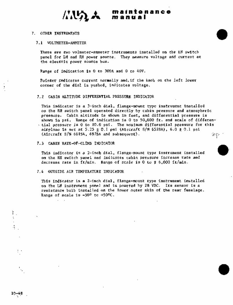
c~sA ni a i at e~.ii a a amanual
7. OTHER INSTRUMENTS
7.1 VOLTMETER-AMMETER
There are two volmeter-armneter instrum~nts installed on the LH switch
panel for LH and RH power source. They measure voltage arid current at
the electric power sdurce bus.
Range of indication is O to 30DAand 0 to 40V.
Pointer Indicates current normally and,if the knot on the left lower
corner of the dial is pushed, indicates voltage.
7.2 CABIN ALTITUDE DIFFERENTIAL PRESSURE INDICATOR
This indicator is a 3-inch dial, flange-mount type instrum~nt installed
on the RH switch panel operated directly by cabin pressure and atmospheric
pressure. Cabin altitude is s~own in feet, and differential pressure is
shown in psi. Range of indication is O to 50,000 ft. and scale of differen-
t tial pressure is O to 10.0 psi. The maximum differential pressure for this
airplane isset at 5.25 f 0.1 psi (Aircraft S/N 652SA), 6.0f 0.1 psi(Aircraft S/N 661SPI, 697SA and subsequent).
7.3 CABIN RATE-OF-CLIMB INDICATOR
This indicator is a 2-inch dial, flange-mount type instrument installed
on the RH switch panel and indicates cabin pressure increase rate and
decrease rate in ft/min. Range of scale is O to f 6,000 ff/min.
7.4 OUTSIDE AIR TEMPERATURE INDICATOR
This indicator is a 2-inch dial, flange-mount type Instrument installed
on the LH instrumentpanel and is powered by 28 VDC. Its sensor is a
resistance bulb installed on the lower outer skin of the´•rear fuselage.Range of scale is -500 to +500C.
P
10-48

A Im a i ii;i;t 8 a a a Q81 ni iii ~ii i
i:;
7ij TROUBEE SH(IOTINC
Tro~ibi;e shob~ing tt~e altitu~e indicator,
cabii~ air indicator, voit-
Trouble Probable cau~e Remedy
Indication of cabin a. Instrument faulty. Replace instrument.
altitude and dif-b; Satic pressure lilie Perform leak check.
ferential p-ressureis erratic
is leaking. (See static pressure
system.)
Indication of cabin Instrument faulty. Replace instrument.
rate-of-climb indi-
catoris erratic´•
Cabin rate-of-climb Zerb adjustment Perfo~m zero adjust-indicator does not erroneous. ment.
indicate zero in
constant cabin
altitude
Indication df out- a. Instrument faulty. Replace instrument.
side air tempara-.b. Broken wire or Perform conductivity
ture indicator ispoor’~contact. t’est and repair
erraticdefective component.
Indication of a. Instrument faulty. Replace instrument.
voltmeter-am-b. Broken wire or Perform conductivity
.meter is erraticpoor contact. test and repair
orit is in-defective component.
operative
10-49(50)

CHAPTER
CABIN EQUIPNIENT

m a i a t a a a a-a-a
man ual
CHAPTER XI
CABIN EQUIPMENT
CONTENTS
i. GENERAL 11- 1
2. PILOT GO-PILOT SEAT 11- 1
2.1 REMOVAL AND INSTALLATION 11- 1
3. INDIVIDUAL RECLINING SEATS 11- 2
3.1 REMOVAL AND INSTALLATION 11- 2
3.2 HYDRAULIC SEAT LOCK 11-3(4)
4. REFRESHMENT CENTERS 11-3 (4)
3-31-90 11-i
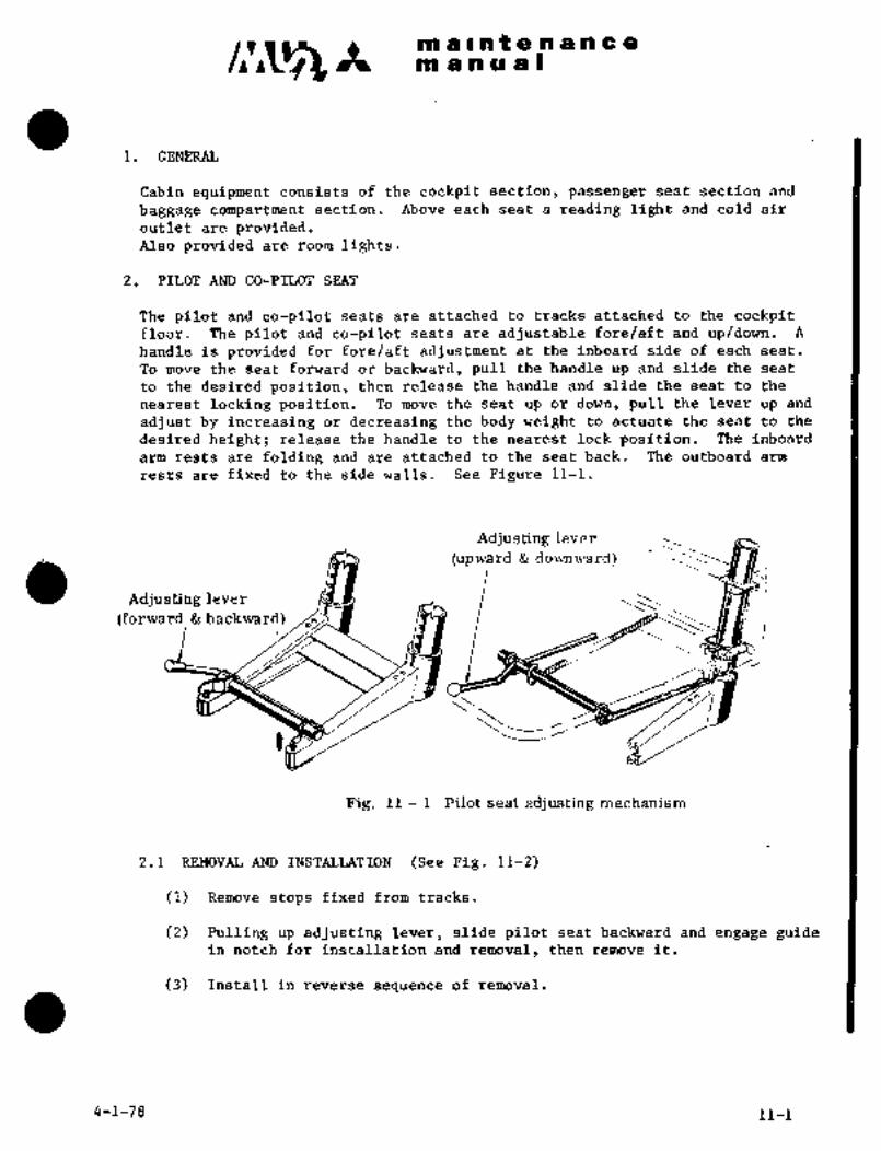
/1~5 It m a I nt.g a a a a a
at a a a a I
1. GENERAL
Cabin equipment consists of the cockpit section, passenger seat section and
baggage compartment section. Above each seat a reading light and cold air
outlet are provided.Also provided are room lights.
2. PILOT AND GO-PILOT SEAT
The pilot and co-pilot seats are attached to tracks attached to the cockpitfloor. The pilot and co-pilot seats are adjustable fore/aft and up/down. A
handleis provided for fore/aft adjustment at the inboard side of each seat.
Tomove the seat forward or backward, pull the handle up and slide the seat
to the desired position, then release the handle and slide the seat to the
nearest locking position. To move the-seat up or down, pull the lever up and
adjust by increasing or decreasing the body weight to actuate the seat to the
desired height; release the hand’le to the nearest lock position. The inboard
arm rests are folding and are attached to the seat back. The outboard arm
rests are fixed to the side walls. See Figure 11-1.
Adjusting lever
(upward downward)
Adjusting lever
(forward backward) ,o
Fig. 11 1 Pilot seat adjusting mechanism
2.1 REMOVAL AND INSTALLATION (See Fig. 11-2)
(1) Remove stops fixed from tracks.
(2) Pulling up adjusting lever, slide pilot seat backward and engage guidein notch for installation and removal, then remove it.
(3) Install in reverse sequence of removal.
4-1-79 11-1

m a Int a a a a a a
m anual
Track
-F~ StopLever
Fig. 11 2 Installation of pilot seat
3. INDIVIDUAL RECLINING SEATS
The individual passenger seats are attached to seat tracks attached to the floor
and fuselage side wall of the passenger compartmenf. The reclining seats can
be adjusted to suit the comfort of the occupant. A button on the inboard side
of each seat adjusts the reclining position. To adjust the reclining angle,push the button and lean forward, then release the button. The side panel of
the cabin may be used as outboard arm rests for the seats. Lift the inboard
arm rest into position. Lift arm rest and then lower for stowing.
3.1 REMOVAL AM) INSTALLATION (See Flg. 11-3)
1. Remove seat stops fromfloor track.
2’; Lift the adjusting´•lever and slide the seat in its facing direction
until the retaining guide is in the appropriate track notch and
remove. Continue to slide the seat until all retaining guides are
removed from the track. Remove the seat.
3. Install in reverse sequence of removal.
NOfE
When installing the seat stops, placea small amount of adhesive on one side
before positioning in the seat track.
11-2 4-1-78

c~s ItmalPlf8nancem a a a a I
´•Track
side 4
cover/ /Side cover
AdjustingI s
Hydraulic seat lever
lock button Hydraulic seat lock
Fig 11-3 One passenger seat
3.2 HYDRAULIC SEAT LOCK
The hydraulic seat lock should be sent to the manufacturer ~(P.L. Porter
Co.) for repair, disassembly and inspection as necessary when an oil leak
is found or an abnormal load has been applied to the seat back due to
emergency landing.
3.2.1 REMOVAL AND INSTALLATION (See Fig. 11-3)
(1) Remove side cover.
(2) Turn hydraulic seat lock counterclockwise
and remove it.
(3) Install in reverse sequence of removal.
4. REFRESRMENT CENTERS
Hot and cold refreshment centers are available to be installed in the passenger
compartment. The refreshment centers contaiqspace available for liquor dis-
pgnsers and bottl~s, ice hot ii~uid container, stereo tape player and availablestorage space.
4-1-78 11~?(4)

CHAPTER
SAFETY EQUIPMENT

maintenancemanual
CHAPTER XII
SAFETY EQUIPMENT
CONTENTS
1. GENERAL 12- 1
2. OXYGEN SYSTEM 12- 1
2.1 GENERAL DESCRIPTION 12- 1
2.2 REMOVAL AND INSTALLATION 12- 1
2.3 INSPECTION 12- 3
2.4 OPERATIONAL TEST 12- 4
2.5 TUBING LEAK TEST 12-4-1/12-4-2
2.6 OXYGEN CYLINDER RECHARGING PROCEDURE 12- 6
3. ~ORTABLE FIRE EXTINGUISHER 12- 7
4. FIRST AID KIT 12- 8
5. EMERGENCY LOCATOR TRANSMITTER (ELT) (If installed) 12- 9
5.1 DESCRIPTION 12- 9
5.2 REMOVAL AND INSTALLATION 12-12
5.3 CHECK 12-13
5.4 OPERATION 12-13
5.5 REPLACEMENT OF BATTERY PACK 12-15
3-31-90 12-i

~´•.´•.´•.:il ~iii icia ii~i u I
irei’ ~st $id ~f are
the aliigfii~t.
i;
i:i ;l~i.i\´•´•.: ~´•´•´•´•l-:rJ-’!´•:.:; .r:..
GENER~ IIESCR’IiPTIt~j
j~lot HIlif ijne´•I~e oxygen dblyijz~i; oxy~enlliri df aa.~fie;gencl; ii~ faili~e
8~ ~ii ig6ij psi (126iB/cm2)~ ii
cui it; d[ji~j´•gen c3lin~eri ´•3 ati~d rria~ics.
Aa Be~ be oxygen fo ti~e
reli~8isiiig Thi~ ~Pt´•idiii ’ddmpl6teiybf an~ impl8ys an 1800 p62 i126.6 kglcm2),
;ICU.~? reguiatoli ~utlets dnd masks (f6r2i ciii ct. (d, i;
thi~ Idcations).
2..2 kEM6~iAL -I.
I .::::[Jv~Before rembv;ng: any comp~entof the’o6ygen -system, ensure
\´•-:that no oxygen.pressure re-
´•-mains’:ini’the system.~:´•
AU´•i I a;‘N:´•I
:..,-’Care:should be;e:sh~ld be exerci$ed.Irjhen handingI tubing-so that itdoeg’; nor come in:-!I: con-j
tact;wlth:any tlpe,-of lubtic~t.
?.2,1 OXYGEN ;CYLINDER
C~ose cyiindet shrttoff
(3j‘:i,iloosen ´•:seciirina. ci~mps. gndIv.´•j;.´•i´•~
’1.´•
be~:necessajr to
’c~bYn;et assembiy
~.1.: .’..:i:.~nbiosi’ng ryli~her (st~n-
:(4):; Install.in reveree sequencd:of te~noval. ]:Apply alignment a$rkafte~.:ti:gheelning tubing:´•cpnnectipns tco.-iptdrs~ .vaiue.

a 4 1 s ~d
.3
rro~ZII1 CI~[5 1
69 J 2
Standard Oxygen System
a ´•s 1~´•
cn
sr ;6
Optional Oxygen System
1. .Oxygen filler valve
2. Oxygen cylinder/pressure gauge
´•3, High pressure tubing4.0xygen regulator a
~5.:Low pressure tubing6. Pilot oxygen.outlet7.. Co-rpilQt oxyged outlet
1 8. Passenger´•oxygen ou’tlet
9. Oxygenmask under.seat oOu:rcOeQr)l~10. Pasaen~er’ oxygen outletaxvcaan 3
(located as :res’d max 7)´•. cvrinPei
11. Oxygen regulator pressure-gauge12, Oxygen regulator shutoff valve REQUCA’POR
Pig. 12-1 Oxygen gystem
12-IESd
m a II nf a .n a a a a
nl a a a a I
2.2.2 OXYGEN REGULATOR
(I) Close cylinder shutoff valve.
(2) Remove co-pilot side panel.
(3) Disconnect high and low pressure tubing from the regulator.
(4) Remove screws attaching regulator valve assembly and remove
regulator valve assembly.
(5) Install in reverse sequence of removal. Apply alignment mark
after tightening tubing connections to proper torque value.
NOTE
Installation torque for oxygen tubingshould be applied the following values.
In case of taper fittings, use Permacel
Tape 1~412 (Permacel Tape Corp.) for
sealing before installation.
120 to 140 in-lbs. (138 to 161 kg/cm).stainless steel or copper tube.
90 to 110 in-lbs. (104 to 127 kg/cm).aluminum tube.
2.3 INSPECTION
dr) Check oxygen cylinder for security of attachment, deformation,
damage and oiliness.
(2) Check oxygen cylinder for pressure of 1500 to 1800 psi (105.5 to
126.6 kg/cm2).
(3) Check pressure gauge for "0" (zero) indication with shutoff valve
of oxygen regulator mounted on side panel in OFF position.
(4) Check oxygen outlets for cleanliness, rust and damage.
(5) Check oxygen mask for cleanliness and damage. Check mask bag for
proper position.
CAUTION
High pressure oxygen is liable
to cause an explosion upon con-
tact with oil, grease, or sol-
vent. The handling should be
done with extreme care.
12-3

maintenanceman ual
2.4 OPERATIONAL TEST
(1) Open cylinder shutoff valve gradually to supply oxygen in the highpressure line.
(2) Make sure indication of regulator pressure gauge is equal to that of
the cylinder gauge.
IWARNING)If oxygen cyl inder valve is not open, the oxygen
pressure gage will indicate the lower pressure in the
system. If the indicated values for the oxygen cylinderand the regulator pressure gage are equal, the cylindervalve is open.
(3) Open regulator shutoff valve.
(4) Plug mask assembly into outlet; put maskon, and breathe normally.Make sure the red mark is not visible in the flow indicator attached
to the mask assembly.
(5) Close regulator shutoff valve.
(6) Close cylinder shutoff valve.
IC*UTION]CAUTION
High pressure oxygen is liable to cause an explosionupon contact with oil, grease, or solvent. Handlingshould be made with extreme care.
NOTE
When bleeding oxygen from the system after operation,close the shutoff valve of the cylinder, check the
pressure gage of the regulator for 3 reading which
indicates system pressure being equal to atomosphericpressure, and close valve of the regulator.
12-4 3-31-90

maintenanceman LI al
2´•5 TUBING LB~K IEST
2.5.1 HIGH PRESSURE TUBING
(1) Close shutoff valves of regulator and cylinder.
(2) Remove filler port cap.
(3) Connect oxygen (Spec. BB-0-925, Grade A, Type 1) or nitrogei~charger (N2: MIL-N-6011, Grade A, Type 1) to filler port.
(4)’ Pressurize system gradually to 1800 f- 50 psi (126.6 f 3.5 kg/cm2).Maintain the pressure 5 to 10 minutes, to allow the tubing and
gas to adjust to room temperature, then close the valve.
(5) Record the regulator pressure gauge indication and the room
temperature.
(6) After 5 minutes perform step (5).
(7) Compensate the pressure for the room temperature in accordance
with Figure 12-2.
(8) Ensure the pressure drop is below’50 psi (3.5 kg/cm2). To cal-
culate the pressure drop, use the following example.
3-31-90 12-4-1/12-4-2

X it~ a i nt a a a ii C Qb
m a a ii a)
Examp~e:-
(a) initial gau~e ptBss;te 1800 psi (126.6 kg/cm2)
(b) InitiaZ ’75PF (240C)
(C) Final gauge preSSure 1780 psi (125 kg/cm2~)(d) Final temperature tdOF (210C)(e) Temperature change (b);(d) i 5bF (3"0)
(f) Pressure change correspoilding to
temperature change(Fig. 12-2) 17 psi (1.2 kg/cm2)(g) Initial gressure compensated for
7joF i~4 C)I 1817 ´•psi (127.8 kg/cm2)
Temperature:rise (8) ’.(a)+(E)Temperaturefall (g) (h)-(f):
(h) Pressure drop (g)-(c)~ j 37 psi (2.6 kg/cm2)
1~0
10U
Pig. ~L2-2 ´•:Initial pressure o
comp.enSation for
tefflpefatltre chan&f?.;
Pc 5()
tps i)
0´•io ’zo´•.so. 40 --60
Temperaturk(P)Change
(9) Should the pressure. drop:exceed: 50 psi. !.5 kg!cm2), proceed as
´•follows~
Remove ~inferior as necessary;
.(b) ´•:With the -system pressurized, apply soap water (MIL-S-4282 or
equivalent):’:to’ all fit~tings and connections of.the high
pressure section from the fillerlport,- including cylinder and
reguiator,.to detect leaksi Repair the leak(s) and recheck
the system.
(10) Restore:´•´• the: aircraft to its~oyiginal’ con’figuration.
12-5

c~Sr´•t´• m a i PI f 8 a a Pi ;e a
iin a ii u d i
PRESSUilE ’rijBINd
Gi-adually cylinde~ valve uintil th~ sjrstem is pregsuriied to
1800 f 50 psi (li6.6 f j.5 kg/cm2
Open the reguiatoi: shutoff TI´•alVe anci pre~surize the low p~essuretubing ii~es;
Apply soap sudS (MIL-S-4282 or equivaient~ to all fittings and
joints. Leakage causing a bubble of 0.24 in. (6.1 mm) in diameter
to be formed 10 secon~s or longer, or a bubble df 0.47 (12 r~m) in
diameter 60 seconds or longer may be permissible. Leakage must be
repaired if found excessive.
Close regulator and shutoff valve.
2.5.3 CHECK AFTER LEAK TEST
~I) Wash the system with clean water and wipe with a dry cloth after
leak test is performed.
(2) If nitrogen is used ~or testing; bleed ‘from.the system and
reduce the system pressure to~that equal to atmospheric.Blow oxygen into the system for cleaning for at least 2 minutes
prior-to recharging.
r.6´• OXYGENCYLINDER RECHARGING PROCEDURE
(1) Connect oxygen supply source to filler port’.
(2) Open cylinder shutoff valve and recharge the cylinder at a chargingrate not to exceed 500 psi/min. (35.2 kg/cm2) until cylinder pressure
gauge indicates 1800 +50. psi (126.6 i 3.5 kg/cm2).
(3) Allow time for the cylinder and oxygen to equalize that of room
temperature, then recheck the ´•cylinder gauge for 1800 f 50 psi
(126.6 3.5 kg/cm2). Recharge if necessary.
(4) Close the cylinder valveand detach supply source from the filler
port and install port cap.
(5) Watch gauge ind~cation for a while to ensu~e no leakage occurs.
12-6
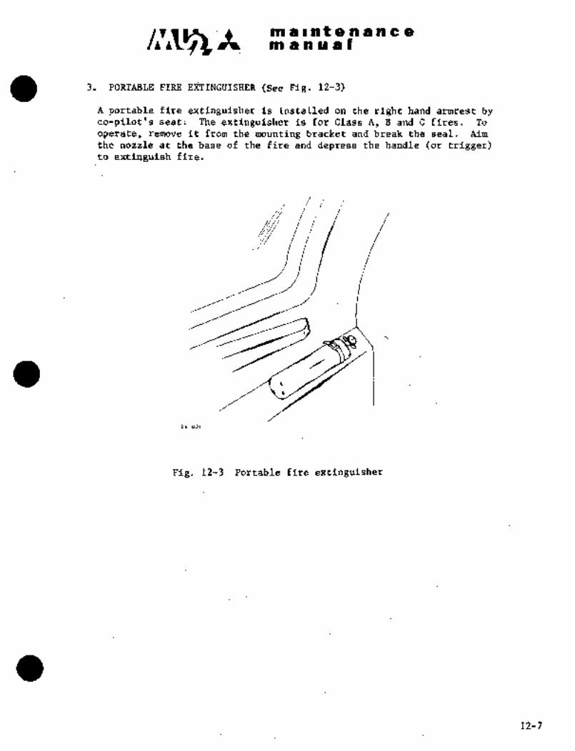
Cllri3 in a i at a a a a a a
~n a a a at
3. PORTABLE FIRE (See Fig. le;~)
A portable fire extinguisher ds :installed i~n the right hand rmrest byCo-pilot~s seat; The extinguisher is for Glass A, B and C fires. To
operate, remb~e it ~rom the mounting bracket and break the seal. kimthe nozzle at the bas~ of the fire and depres~ tB´•e handle’(or trigger)to fire.
26 001
Pig. 12-3´•´• Portable fire extinguisher
´•12-7’

iii ~i i:n t ~g ii ill ii ic ;iinl dnu ti I
4. P~kST AIjJ Kfli~ isee F~s. ii-4)
The fir~f aid irit i$ iinstaiiei ~n the side of fhe peirsohal convenience
center. To remove, pull the bottom up slightly and lift from the two
screw heads.
The first´•aid kit and suppliesare from Scott Aviation, Lancaster, New
York, 14086. The kit contains sterile adhesive bandages; trianglebandages and bandage compresses; iodine swabs; carbolated petrolatumi and
ammonia inhalant. ~he kit lid may contain general instructionS for ddminis-
tering inrmediate first aid for common injuries.
The equipment and supplies in the kit should be checked periodically and
items replenished as required after each usage.
a i
First aid kit
Fig. 1274 First aid kit
12-8

maintenanceman ual
5. EMERGENCI LOCATOR TRANSMITTER (ELT) (If installed)
5.1 DESCRIPTION
Emergency locator transmitter (ELT, DORNE and MARGOLIN Inc.) is a
transmitter to assist in locating downed aircraft and is operableunder a wide range of environmental conditions.
ELT consists of transmitter (including battery pack), antenna and
control switch. (See Figure 12-5)
(1) Transmitter and battery
(a) Transmitter is equipped with internal battery pack, composed of 6
long life alkaline D type cells operable at low temperatures.Battery pack is installed in transmitter properly separated from
transmitter electronic circuit.
(b) G switch incorporated in transmitter detects abnormal shocks in
airplane, and automatically turns on transmitter.
(2) Antenna
(a) DM ELT 6 unit utilizes flexible antenna installed inside dorsal fin.
(3) Control switch
(a) Control switch is installed on switch panel to allow remote control
from cockpit.
Transmitter is installed at upper part of aft fuselage. (See Fig 12-6
(1/3))
Flexible antenna is installed protruding into interior of dorsal fin.
(See Fig 12-6 (2/3))
Toggle type remote control switch is installed on auxiliary switch panelin left switch panel. (See Fig 12-6 (3/3))
Transmitter
ANTENNA
Antenna
R~IIOTF IION/TESTI
N.O.
Control Switch
Fig.12-5 ELT schematic diagram
3-31-90 12-9
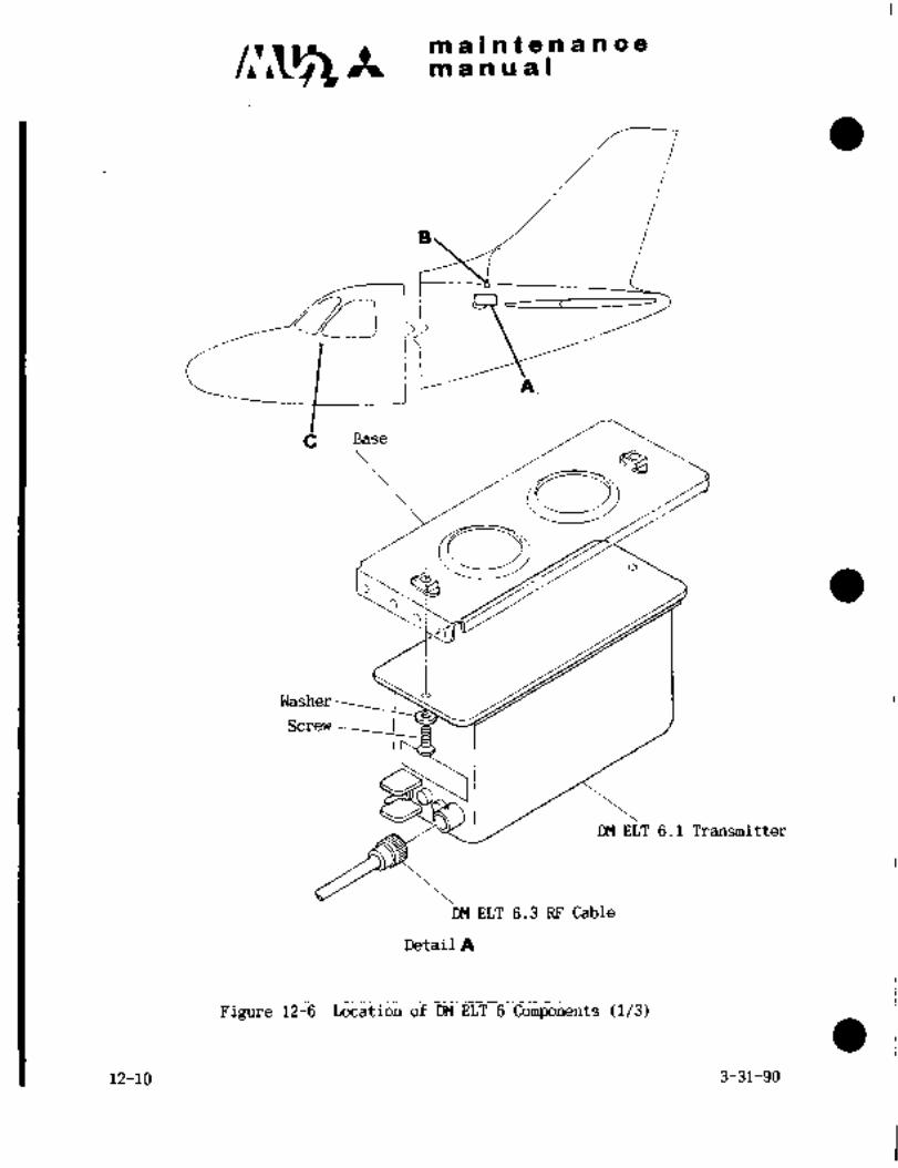
c~r Itmaintenancem a a a a I
_._*~-1
´•::J~ j G- A
C Base
iY0~3:
Washer
Screw
DM ELT 6.1 Transmitter
DM ELT 6.3 RF Cable
Detail A
Figure 12-6 Location of DM ELT 6 Components (1/3)
12-10 3-31-90

c~ Itm a i a t a a a n:e a
manual
Strain Relief Boot
Nut
Skin
DM ELT 6.2 Flexible Antenna
DM ELT 6.3 RF Cable
Detail a
Figure 12-6 Location of DM ELT 6 Components (2/3)
3-31-90 .12-11

c~smaintenancemanual
I
cI I
Detail C
Fig. 12-6 Control switch Installation (3/3)
5.2 REMOVAL AM) INSTALLATION
5.2.1 REMOVAL OF ELT 6.1 TRANSMITTER
(1) Open aft fuselage door, and make access to transmitter.
(2) Disconnect DM ELT 6.3 RF matching cable assembly from transmitter.
(3) Remove screws and washers securing transmitter to base.
(4) Remove transmitter from airplane.
5.2.2 INSTALLATION OF DM ELT 6.1 TRANSMITTER
(1) Position transmitter on base, and secure with screws and washers.
(2) Connect RF cable assembly to transmitter.
(3) Do operation test.
5.2.3 REMOVAL OF DM ELT 6.2 FLEXIBLE ANIENNA.
(1) Remove dorsal fin.
(2) Open aft fuselage door.
(3) Disconnect DM ELT 6.3 RF matching cable assembly from antenna.
(4) Remove nuts, and then remove antenna.
12-12 3-31-90

maintenancemanual
5.2.4 INSTALLATION OF DM ELT FLEXIBLE ANTENNA
(1) Position antenna in the interior of dorsal fin.
(2) Secure antenna with nuts.
(3) Connect RF cable to antenna.
(4) Do operation test.
(5) Install dorsal fin.
5.3 CHECK
5.3.1 VISUALLY CHECK TRANSMITTER COMPONENTS
(1) Check for evidence of damage in antenna assembly, and ensure it is
correctly installed.
(2) Check for evidence of corrosion in transmitter, battery packassembly and surrounding structures. Check condition ofinstallation and base for evidence of damage and function switch.
(3) To check transmitter, remove antenna of unit.
5.3.2 BATTERY PACK
(1) Replace battery pack when emergency locator transmitter (ELT) was
used one hour or over in total, and/or the battery reached its
usable period.
(a) Date showing usable period is marked on battery by maker.
(b) Whenever battery is installed in ELT, note the battery usable
period on the space provided on Name and Data Plate of ELT unit.
(2) Operation time of battery pack should be recorded when doingoperation test on ELT unit with battery pack power. Replacebattery when battery pack has been operated one hour in total.
5.4 OPERATION
5.4.1 OPERATION OF SWITCHES
ELT unit is automatically turned on by a shock given to impulse ("G")switch, or manually turned on with remote control switch.
(1) Impulse switch functions and turns on transmitter when it is givena force of 5+2/-0 g for 11+5/-0 milliseconds to the direction of
longitudinal axis of airplane.
3-31-90 12-13
c~r~tmaintenancemanual
(2) If ELT does not operate at crashed landing, it can be manuallyoperated with remote control switch. Impulse ("G") switch
functions only when ELT is set to automatic mode.
That is, it functions only when "ON/OFF/AUTO" switch on transmitter
front panel is set to "AUTO". When resetting transmitter to
automatic mode after it was turned off, set remote control´• switch
to "ON/TEST" and then reset to "AUTO". When transmitter functions,modulating signals are transmitted with emergency frequencies of
121.50 and 243.00 Hz simultaneously. Modulating signal is a 700 Hz
sweep signal. (Max. 1600 Hz, Min. 300 Hz)In normal operations, remote control switch is set to "AUTO"
position. Transmitter automatically operatesby shock and sends
emergency distress signal. Impulse switch can be reset as follows
when transmitter is accidentally turned on by impulse switch for
some reason.
(3) Set remote control switch to "ON/TEST" position, and then reset to
"AUTO"
5.4.2 OPERATION TEST
(1) Obtain authorization from control tower and flight service station
for monitoring of ELT.
(2) Operate ELT unit.
(a) Ensure transmitter "ON/OFF/AUTO" switch is at "AUTO"
(b) Communicate with control tower, and set remote control switch to
"ON/TEST" to test ELT unit. After testing, reset remote control
switch to "AUTO", or communicate with control tower, and set
transmitter "ON/OFF/AUTO" switch to "ON" to test ELT unit.
After testing, reset "ON/OFF/AUTO" switch to "AUTO"
CAUTION
Authorization by control tower and flight service
station should always be obtained before checkingoperation of ELT.
(C) Record the length of time powered transmitter with battery pack.Total time should conform to replacement and inspection schedules.
12-14 3-31-90
maintenancemanual
5.5 REPLACEMENT OF BATTERY PACK
NOTE
Replace battery pack when total operation time
exceeds one hour, or usable period of battery is
exceeded
(1) Set transmitter "ON/OFF/AUTO". switch to "OFF".
(2) Disconnect transmitter RF cable.
(3) Remove transmitter from airplane.
(4) Loosen screw securing base to bottom of transmitter, and remove base.
(5) Disconnect and remove battery pack from unit.
(6) Replace with new battery pack, DM ELT 6.13 or DM ELT 8.B.
(7) Reassemble and reinstall transmitter.
(8) Connect transmitter to antenna.
(9) Do operation test.
(10) Stamp on transmitter the date replaced with new battery. Date on
battery pack and transmitter should be the same.
3-31-90 12-15

CHAPTER
ELECTRICAL SYSTEIVI

c~s It maintenanceman ual
CHAPTER XIII
ELECTRICAL SYSTEM
CONTENTS
PAGE
1. GENERAL 13-1
1.1 GENERAL DESCRIPTION 13-1
1.2 POWER DISTRIBUTION SYSTEM 13-3
1.3 AIRPLANE WIRING´• 13-20
1.5 TROUBLE SHOOTING FOR ELECTRICAL SYSTEM 13-23(24) I1.4 INSPECTION AND MAINTENANCE OF ELECTRICAL SYSTEM 13-23(24)
2. DC POWER SUPPLY SYSTEM 13-25
2.1 GENERAL DESC~IPTION 13-25
2.2 DC G EN ERATO R 13-30
2.3 VOLTAG E REGU LATO R 13-32
2.4 REVERSE CURRENT CUTOUT: RELAY 13-32
2.5 OVERVOLTAGE PROTECTING RELAY 13-32
2.6 VOLTAGE SENSING UNIT´• 13-32
2.7 CHECKOUT AND ADJUSTMENT OF DC POWER SYSTEM 13-33
2.8 TROUBLE SHOOTING DC POWER SYSTEM 13-43
2.9 BATTERY 13-50
3. AC POWER SUPPLY SYSTEM 13-61
3.1 GENERAL DESCRIPTION 13-61
3.2 INVERTER 13-61
3.3 INSPECTION OF AC POWER SOURCE SYSTEM 13-62
3.4 TROUBLE SHOOTING AC POWER SYSTEM 13-63
4. LIGHTING 13-64
4.1 LANDING AND TAXI LIGHT´• 13-64
4.2 TIP TANK TAXI LIGHT 13-65
4.3 NAVIGATION LIGHT 13-66
4.4 ANTI-COLLISION LIGHT 13-66
4.5 STROBE LIGHT´• i 13-67
4.6 ]CE INSPECTION LIGHT 13-68
3-31-90 13~i

c,~s’maintena nce
manual
4.8 PANEL LIGHT 13-69
4.7 INSTRUMENT LIGHT 13-68
4.9 RADIO CONTROLLER PANEL LIGHT 13-69
4.10 TRIM INDICATOR LIGHT´• 13-69
4.11 MAP AND CENTER PEDESTAL LIGHT 13-70
4.12 MAP LIGHT 13-70
4.13 ROOM LIGHT 13-70
4.14 READING LIGHT 13-70
4.15 PRIVATE ROOM LIGHT 13-70
4.16 CABIN SIGN LIGHT 13-71
4.17 CIRCUIT BREAKER PANEL LIGHT 13-71
4.18 CIGARETTE LIGHTER 13-71
4.19 LAMPS AND FUSES 13-72
5. WARNING SYSTEMS 13-73
5.1 STALL WARNING SYSTEM 13-73
5.2 ENGINE FIRE DETECTION SYSTEM 13-76
5.3 OUTER TANK FUEL LOW PRESSURE WARNING SYSTEM´• 13-78
5.4 LANDING GEAR WARNING SYSTEM 13-78
5.5 MASTER CAUTION SYSTEM AND ANNUNCIATOR PANEL 13-79(80)
5.6 FUEL LOWLEVEL WARNING SYSTEM 13-83
5.7 (DELETED)
5.8 BOOST PUMP FAILURE WARNING SYSTEM r3-84
5.9 FUEL FILTER BYPASS WARNING SYSTEM 13-84
5.10 CABIN PRESSURE WARNING SYSTEM 13-85
5.11 AIR CONDITIONING FAILURE WARNING SYSTEM 13-85
5.12 DEFOG AIR TEMPERATURE WARNING SYSTEM 13-85
5.13 ENTRANCE DOOR OPEN WARNING SYSTEM´• 13-85
5.14 HEATED WINDSHIELD ANTI-ICE TEMPERATURE WARNING SYSTEM
(Aircraft S/N 661SA, 697SA and subsequent) 13-85
5.15 TURN/BANK INDICATOR POWER WARNING SYSTEM 13-86
5.16 VACUUM PRESSURE WARNING SYSTEM 13-86
5.17 GENERATOR FAILURE WARNING SYSTEM 13-86
5.18 FEEDER FAILURE WARNING SYSTEM 13-86
5.19 INVERTER FAILURE WARNING SYSTEM 13-87
5.20 INDICATING LIGHT 13-87
5.22 BATTERY TEMPERATURE WARNING´•SYSTEM 13-89
5.22 ICE DETECTOR SYSTEM (SHIPS MODIFIED BY S/B No.080/30-003A) 13-92
13-ii 12-27-99
;r~S´•r a ~in a n t a ’ii a in a a
tin a a a a I
i. GENERAL
1;1 GENERAL DESCRIPTION
The electrical system consists df a negative grounded 28 VDC power
supply, and one liile grounded, single phase, 400 Hz; constant frequency,AC power supply with associated wiring and protective deviCes. The DC
electric power supplyis the primary electrical power source for the
airplane and is supplied_by two-generators; two batteries; or by ´•an
external power supply through an external power receptacle. The batteries
are used forenginestarting and as electrical power in case of no
power being supplied´• from the generator. Two nickel cadmium typebatteries are installed in order to facilitate engine Startingdur-ing cold weather. When the battery switch.is turned to ON, the two
batteries are connected to the main bus, in parallel. While startingan engine, the batteries can be connected .automatically, in parallel or
series, to thestarter bya battery selector switch. A DC generator,with a nominal output of 30V, 200A, is installed on each engine,.supply-ing power to the airplane electrical systems for operation and batterycharging. Eachgenerator circuit: is provided wi´•th a reverse current
relay which prevents current from the battery flowing back to the
generator, and a shunt for the ammeter. The output voltage~of each
External power can be connected directly to the airplane by connection
generator is kept constant by ~a rransistorized voltage regulator.
of an external power. source to the receptacl~-located forward of’the LH
electrical compartment door. When the MASTER switch, located on the LH
switch panel, is placed in EMER positioni all elecfric power sources in
the airplane are cutoff; The left and.right engin’e fire detectingcircuits remain operative, even when the master switch is placed in EMER
position,´•because the circuits are directly operated by battery. The
MASTER switch is used only in case of emergencies such as.an.electrical
fire, forced landing,.etc’., and is normally protected by a switch guardin~the NORMALposition.´• The amperage output of each generator and
voltage of the monitored bus is indicated by a volt-armneter on the LH
switch panel. Unusually high voltagefrom the: generators is detected
by an overvolt~ge protecting relay;lfa generator fails, it is auto-
matically disconnected:by reverse. current cut~ut relay from the.aircraft
electrical bus. When the generatoris cut off from the-bus, the L(R) DC
GEN OUT warning"li~ht´• on the annunciator p.anel illuminates,’ Alternatingcurrent is providea by means of a static.inverter that is installed in
the LH side of the’electrical compartment.
13-1

mblni8nan~8nl in ii a I
FJ~ile starti’ng an engine, the AC’irolt~age ~oittput drops, foliowingany DC power drops. In order to prev~nt this d~op, a DC-DC converter,operated only during engine start, is installed and normal AC power is
generated and supplied to the interstage turbinetemperature indicator
(ITT) (Aircraft S/N 652SA only). After an engine start,´• the DC-DC
converter is automatically cut off. A single phase, 250V, 400 Hz
inverter supplies the air conditioning system, fuel quantity indicatingsystem and engine instrument system with the required AC power. Inverter
failure is detected by an inverter fail relay and indicated by an INVERTER
FAIL warning light on the annunciator panel. The electrical circuit of
each system is protected by trip-free circuit breakers or fuses. The
majority of circuit breakers are installed- on the circuit breaker panelto the left side of the pilot seat. Some circuit breakers foranti-
icing are in the overheadswitch console.
The circuit breakers for the cabin lighting engine start circuits,utility and fuses for the DC power source (ammeters, generator voltage,etc,) are installed in the upper LH side of the main junction box.
CAUTION
Circuit breakers once tripped due to excessive
current cannot be reset as long as an overload’
current exists. Circuit breakers which trip twice
should not be reset except in an emergency.
When necessary, extreme care should be exercised
to prevent electrical fire when resetting the
circuit breaker. The number of manual circuit
breaker operations on the ground should be keptto a minimum.
Warning lights which are important to flight safety are grouped on the
annunciator panel and a master caution light is used for general caution.
Two landing lights are installed on each side of the lower´•surface of
the forward fuselage and one in each tip tank. Anti-collision lightsare installed on the lower surface of the fuselage and on top the vertical
stabilizer. ,Navigation lights and strobe lights are installed~on LH and
RH wing tips and ~aft fuselage and also an ice inspection light on LH center
wing leading edge fillet. Cabin room lights and reading lighrsareinstalled in the cabin. Room lights and map reading lights areinstalled
in-the cabin. Room lights and map reading lights are provided in the cock-
pit. Illumination of flight instruments, engine in~struments, and switch
panels ca;z be adjusted independently b’y the rheostats located in the over-
head switch console. Location of the:electrical equipment is shown in
Figs. 13-1 through 13-12.
13-2
c~s m a Int a a a a ca
~n a a a al
1.2 POWER DISTRIBUTION SYSTEM
In the DC power system, LH and RH generators are connected to the LH andRH main bus through individual reverse current cutout relays installed
on the main junctidn box. The No. 1 battery is connected to the main
bus and the No. 2 battery and the external power source are connected
to the mainbus´•th~ough the starter bus and the series parallel relay.
The LH and RH main buses are connected with power circuit breaker.. In
the cockpit circuit breaker Ijanel, there are the LH and RH buses which
are supplied power fro~ the LH and RH main buses through feeder-protectedcircuit breaker, feeder and reverse current cutout diode. !When the
feeder-protected breaker is~.tripped due to failure, etc., the L(R) FEEDER
OUT warning in the annunciator panel illuminates’ for warning.
The bus in the overheadswitch console is supplied by power through the
circuit breaker OVERHEAD PANELlocated on the circuit breaker panel,left side of, pilot seat´•, LH and RH power for radio equipment is suppliedfrom the load bus through a toggle type circuit breaker. The AC power
distribution system from the inverter supplies power from the electrical
comp’artment, LH to the circuit breaker panel, left of the pilot seat.
AC power is, supplied to the fuel quantity indicator system and engineinstrument system through circuit breaker. The AC power 26V, 400 Hz
necessary for the engine instrumentation system is provided by the
main or standby inverter in the and is supplied to
the circuit breaker.
"´•i: "j ir tsM

lil a i i~ t a n a n ;i= am a a a a
i, 1
I;Ik z
32
4’ 6, 78~ 33
9.33
17 --~Y U~J7 /1511
13 16 X f´•4
31/ ~I I I \X ‘31
12 12
2421- 18 20\19
23’’22
26 n n i27
31
28 29
i. Landing and taxi light 17. Flap motor (Center wing
2. Connection box trailing edge)3. LH instrument panel 18. Propeller de-icer timer
4. -RH instrument panel 19. Landing gear motor
5. LH switch panel 20. Landing gear control relay
6. ph switch panel tin bulge)7. Center pedestal switch panel 21. Main junction box
8. Overhead switch console 22. Inverter
9. Anticollision light 23´• External power receptacle
(Fuselage lower surface) 24. Wing de-icer timer
10. Circuit breaker panel 25. Air conditioning controller
11. Start~r generator 26. No. 1 battery
12. Trim aileron actuator 27. No. 2 battery
13. LH wing tip light 28. Anti-collision light
.14. RH wing tip light (Vertical stabilizer)
15. Relay- panel (Center wlng´•..:_
29. Tail lightleading edge) 30. Ice inspection light
16. Landing gear~´•ddor´• actuator 31.´•´• strobe li~ghttin bulge) iftl) 32. Heated windshield anti-ice
controller sr relay33. Tip ~8nk taxi light
*1 Aircrafts;/N 661SA, 697SA and subsequent
Fig. Main electrical equipments13-4

m alnaenancera a a a a I
1415
9 -’~-C3 to
1
)!i
12II
13
i
12 i
r,
7 .8
1. LH instrument panel. 8. Radio panel
2. RH instrument panel 9.. I;H upperswitch panel (kl)
3. Shroud switch panel ’10. RH upper switch panel (kl)
4. LH switch panel ii.- Annunciator panel
5. Engine &’instr. panel 12. Circuit breaker. panel6. RH switch panel (See 13. Circuit breaker panel light
Fig. 13-’4)14. ´•Center pedestal lighting panel (nl)
7. Center pedestal switch
panel’j’(See Fig. 13-3)15. Ovel-head switch console (jt2)
16. Loadmeter &selector switch (j(2)
kl aircyaftS/N 652SA
´•k2 ~Airciaft SIN661SA,’697SA and:s~ubsequent
Fig.’l3-2 rCd’ckpit~ electr´•ical install’ation’

bn i i ii t e a a in aan a a 9 a I
2 3
(4~DU
5 10 (~kl)
0‘
/M I
i. Beta range light. 7. Aiieron trim indicator
2. Engine start switch 8; Aileron trim control switch
3. Engine crank run stop switch 9i Flap controller
4. Unfeathering switch 10. Manual propeller de-ice
switch (´•kl)5. Start fuel enrich switch
11. Manual propeller de-ice6. Engine start select´•switch
indicator light (*1)
Fig.’ 1’3-3-:Center pedestal Switch panel
~1 Aircraft S/N 652SA only
13-6

maintenance
c~s It manual
On ?O 21 22 23 2p
O52 04
O 42 .43 Y ,’57
a1 ao ooo
8BB I )\I I //Y;- luL rt;hh\~\\l I I un 16
)231\’" j5
34 ii53 ~3 14 16
56 Is25 12 ISIn 19
1. MASTER SWITCH 31. OIL PRESSURE INDICATOR2. BATTERY SWITCH 32. FUEL PRESSURE INDICATOR3. DC GENERATOR CONTROL SWITCHES 33. OIL TEMPERATURE INDICATOR4. INVERTER SWITCH 34. MAIN TANK FUEL QUANTITY INDICATOR5. MICROPHONE JACK 35. TIP TANK FUEL QUANTITY INDICATOR6. VOLTAMMETERS 36. FUEL CONSUMPTION TOTALIZER7. MAIN FUEL VALVE SWITCHES’ 37. BETA RANGE INDICATOR LIGHTS8. TRANSFER SWITCHES 38. OUTER WING TANK FUEL EMPTY9. POWER AUTO LIMIT SWITCHES WARNING LIGHTS
1O. TRIM AILERON SELECT SWITCH 39. POWER AUTO LIMIT TEST SWITCHES11. LANDING GEAR CONTROL SWITCH 40. PANEL INDICATOR LIGHT TEST SWITCH12. LANDING GEAR POSITION INDICATING LIGHTS 41. FUEL QUANTITY INDICATOR TEST SWITCH
13. LANDING GEAR UNSAFE LIGHT 42. STALL WARNING TEST SWITCH14. LANDING GEAR´•HORN CUTOUT SWITCH 43. FUEL LOW LEVEL TEST SWITCH15. FLAP SWITCH 44. PROPELLER SYNCHROPHASER SWITCH16. AIR CONDITIONING CONTROL PANEL 45. VACUUM GUAGE17. CABIN CONTROLLER 46. AIRSPEED INDICATOR18. CABIN ALTITUDE DIFFERENTIAL 47. ATTITUDE GYRO
PRESSURE INDICATOR 48. ALTIMETER19. CABIN RATE OF CLIMB INDICATOR 49. RATE OF CLIMB INDICATOR20. LH ENGINE FIRE WARNING LIGHT AND 50. TURN AND BANK INDICATOR
FIRE EXTINGUISHER HANDLE 51. TURN AND BANK INDICATOR POWER21. ENGINE FIRE DETECTOR TEST BUTTON FAIL LIGHT22. MASTER CAUTION LIGHT 52. DEFOG AIR OVER TEMPERATURE23. MASTER CAUTION SYSTEM TEST SWITCH WARNING LIGHT24. RH ENGINE FIRE WARNING LIGHT AND 53. BATTERY TEMPERATURE INDICATOR
FIRE EXTINGUISHER HANDLE AND ISOLATE SWITCHES25. OUTSIDE AIR TEMPERATURE INDICATOR 54. HOUR METER26. CLOCK 55. CABIN SIGN LIGHT SWITCH (S/N 652 only)27. TORQUE METERS 56. ALTERNATE STATIC SELECT VALVE28. ITT INDICATORS 57. CONTINUOUS IGNITION INDICATOR LIGHT29. FUEL FLOW INDICATORS ii installed)30. TACHOMETERS 58. CONTINUOUS IGNITION SWITCH (If installed)
59. ELT CONTROL SWITCH (If installed)
Fig.13-4 Instrument and Switch Panel (?lypical)
3-31-90 13-7
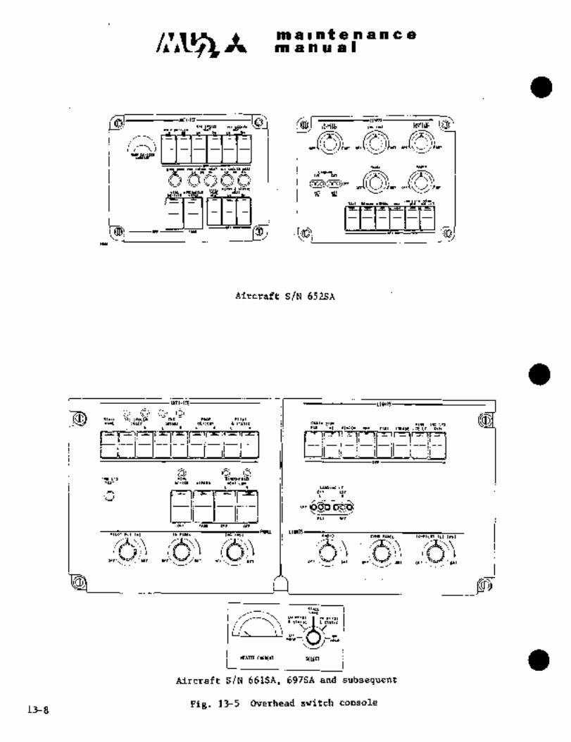
maintenancemanual
0’~41"
uolollri 1101 Di ln*12 IE*T DIL COQEI *UT
m in or an
m
IJ~ )I~ 1 I:L:ICIC1T B ~T
Till wro.rmosr uv "ODWR1S:~r
Aircraft S/N652SA
STILL OILCMOLEa EWb WlOs PITOTVINE INLET I*T*IE DE~ICER (ITLTIC c~sl* IIIO(l *1*6 INm LTs
L a L a L R L R II FIBBELCOII UY TUI STROBEICELT DIN
BTEST DE-ICE IIPERI XEIT LO*
L R UIIDI*b LT
EXT EXTO I
SET RET
OFF FIFr OFF OFF
LIRTSPILOT FL~ IYIT )U(IL EY(I 111~7 1*010 OVW PIIIEL CO-P1LOT FLT IYST
OFF OFF OFTear aFF/sRTIBIT
STUL1111
Ln PITO’I aH PITmIsnrle Pn*rle
LH _I \j IIH
"OP-i P rR1OP
IIEATER CURREKI SELECT
Aircraft S/N 661SA, 697SA and subsequent
Fig. 13-5 Overhead srJitch console13-8
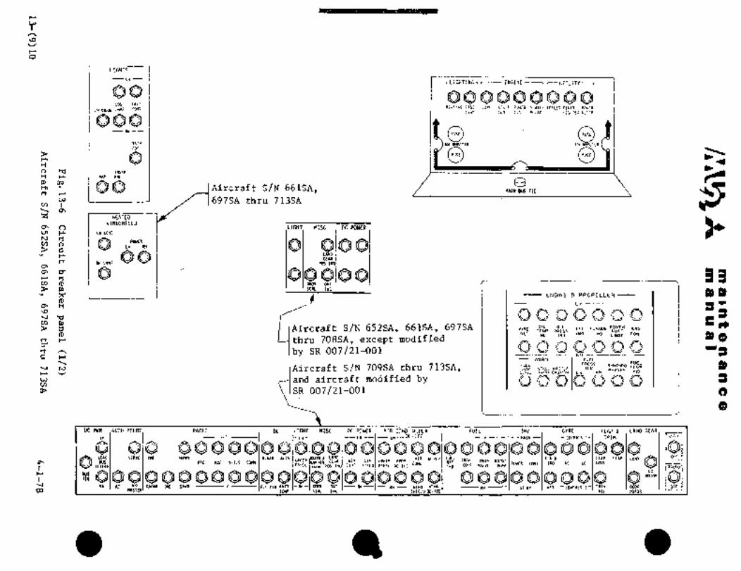
W
h
\Ov
r
O
LIBITS
LHrLiGHTINGI ~--ENGINE-1
QO OOQQQQQQOLOC TRYI
RELOING P:SS CSNV ST;^i Pry~ER SLillfS TOILiiCIWIR WWERIHTEGRIULWP CONIS;;N COYI CG$I RELRY Li;HiEi RLtiF
QOOFUSE FUSE
7Pir 1(1( /U9lETER LH Z~tTL9
dBFUSE FUSE
0 r InsiR
Y R9P PR
P, 09 I Aircraf t S/N 661SA, IV\II( BUS nEm´•rrr
4´•’ 1697SA thru 713SA
I HEATEDWINDSHIELD
O\ n LIMT MISC .OCWWER99 ~-I. LH COM
V)N nrc WUER
RH CONI
Q QIQQu\no5555
rt POS0\
QQ QQ~n 91 moR Onr
P, I I ’5EPI IHD ~19)Y 71’ ENGINE 8 PROPELLER
0
3o\
B Aircraft S/N 652SA, 661SA, 697SA TI.EOIL Oli ITTTOR~UFPOWER ENG
cPTEMP PRESS nu~o
m orr tao IND CONT
thru 708SA, except modified*a INo
by SR 007/21-001 O Q OQ Q Q Q 588
RHr
WnRN FUEL
8),v ;IA~rcraft S/N 709SA thru 713SA, PRESS
PHIZSEH FUELINDSYNCHRO FL.OW10 LOIY Si~i MI5iLP INC
LEYEL V~RN CPUT")1I Ln HH
3and aircraft modified bywc~
SR 007/21-001
o
DCPWR ~AUTOPILOT. RADIO DC LIGHT NISC OC POWER I\IR COND WIPER FUEL INY GYRO FLAP LAND GEAR
LH LH LH --OE-ICE IILH cn:PAss 1- TRIM i: ~oia
6 6 6QQ Q Q’Q Q Q QI~ QIQ Q Q QiO O Q Q QIO QIQ iif.
~log QQ000V/ILS CO~ YUYLLR
GEAR GEII tE9 UPPE’( PPOP OTICOr(i
RIN BOOSTY’" L´•*O "~dFULL
BUS UPPERATC ADi CONC P~IR MM IND AC DC COIIT
Plr:EL p0S INDI COHT FIFLD PPN’L OC-ICt IHD YILYE PUIIP
BU5 QIQ O OQ000Q QOQ ~d QIQ O Q O Q noran i;QnE
RH IC RADL\R DEe SPKR OIRBATT RH DOOR OPiT --RH----RH-- wine wrle ST BI PITT -COWPMS 2- TRIH IWOR II OFr ii03 TERP SERL IND SHIELO OE-ICE 1II HOTc9
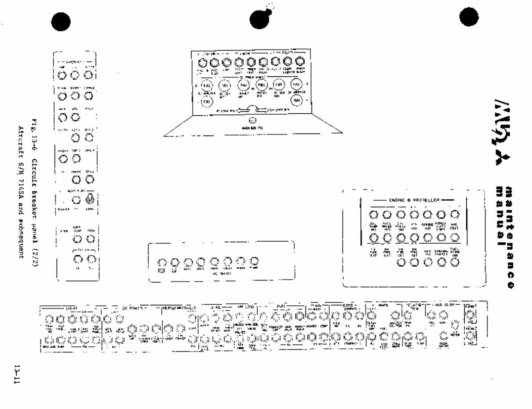
rllMTING~ UTILITY I
--I~YIONICS
---vuEj,L~I u/cSZOQO660Q6QSEAOI’IGPIISS tOliV Sii~ST PMER SERIES iOi~ii CIGAR FOYER
Lil 116H iOhi LOIIT RTiin
R-N1I~I COBM: LOMLLP i FUSE O ,E,, OFUSE FUSE NSE FUSE
OOQ ,*~rrRarm irmta aron o~smwuma
0ur OUT OUT OUT
,EFUSE
?I1(R nTC21 I RH LOAD d
rrQO I er
09 TEIPH PIOF~ ~OF 2~L111 BUI ~IE
´•o" t;P, a~
RaolR OMLI OMEZ
rn r.
~Z o HF DHONE SP14
5.r .rr
r-nuTo ´•,ior 33f-
04 ENGINE 8 PROPELLER~P ct
(D 3)3)d, a,3;’ I´•nvooEs oc coN1
a (p
:MOIL FUEL OIL ITT TORaUE POWER ENO’d TEMP PRESS PRESS IUTOBATT IND IND LIUIT CONT:a a) IHe InD INO
QQ on,I
aLT DIR LH RH LH RH FUELr FIRE FIRE FIRE FIRE 0*T SYHCHROFLOW
h, IND PWISER IND 3)rtm EXT OLi DET
QQQQOQQQFLTOIR LDFI 1DFt WLSIL\C RnDIOV/ILS2
ll*OU1 JDc HOG
C)
(D
~Ii,NDGE~IR--WARN 1- FLAP B
Rnoaoc POWER -----IMmED WU~tilELD DE-ICE BIRCOND -------FUEL
Q 8I,51 ;3~ 8 O Qt8 010 O 018I~ 018 Q--iH- -Lr--
----LH---- -M*IN-- -LH- TRIM--LH-- -LH-
8000is318Qs~rm wu~ u´• Q
P05 RZKL LMiB~nXI LPPER GEN CEN C~NT PROP IIP~ER AIR YALYEBOOSTPOWER CCNT IND DC IC F~EL bit
IND LL1IIP COIIT P~EL FIELD DE-ICE Fe~riEi CONT ~LVE PUMP Ek~ FUEC
Om.--I
’"O---RH---- --RH -Rn- I AIR DOOR TIP07~ --ST B(- D~TT COMPASS Z -R*- LOW ST~LL neiP P~IP OCCR0008~08
OFFWVIG -RH-- LEML HI\RN carr
DE.I-E CORD sEnL !ND-----------_--------
C1
.C*T
r
r

sP~ a 191f 8 a a a a a
n~ a a or a I
FUEL LOW
L BOOST PUMP FAIL
F.BOOST PT_rlMP FAIL
L FUEL FII, BYPASS
R I;’UEL FIL BYPASS
L FEEDER OUT
R FEEDER OUT
INST VAC FAIL
ENT DOOR OPEN
L DC GEN OUT
R DC GEN OUT
INVERTER FAIL
CABIN PRESS LOW
Aircraft S/N 652SA and 661SA
Fig.13-7 Annunciator panel (1/2)
13-12 4-1-78
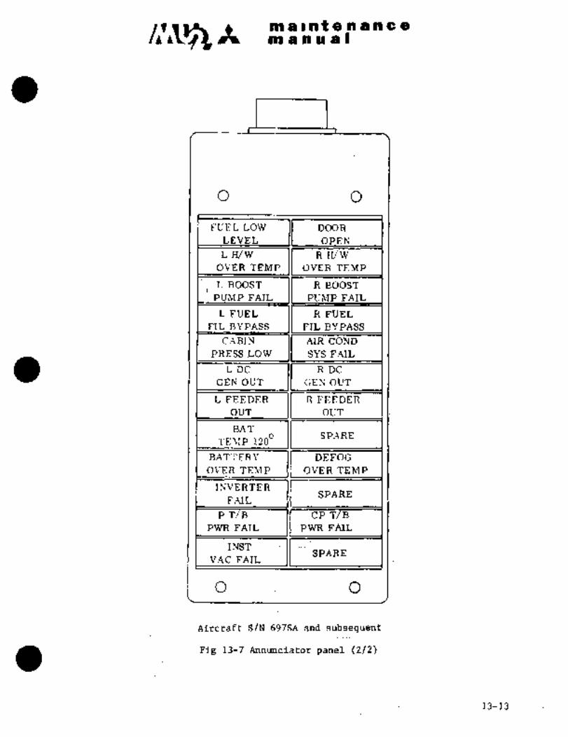
~a a I’nt(b a a a a a
m a a a a I
o o
FUEL iOW DOOR
LEVEL OPEN
LH/W R H/WOVER TEMP OVER TEMP
LBOOST RBOOST
PUMP FAIL PUMP FAIL
LFUEL RFUEL
FTL BYPASS FIL BYPASS
C~BIN AIR COND
PRESS LOW SYS FAIL
LDC. RDC
GEN OUT GEN OUT
LFEEDER RFEEDER
OUT OCTT
BAT
?’EMP. 1200 SPARE
RATTERY DEFOG
OVER TEMP OVER TEMP
INVERTERSPARE
FAIL
PT/B CP B
PWR FAIL PWR FAIL
INSTSPARE
VAC .FAIL
´•O O
Aircraf’tS/N 697SA and subsequent
Fig 13-7 Annuncidtor panel (2/2)
13-13.

c~nmaintenancem n ii gi I
22
21
20 ORIGINAL19 As Received By
23 ,2,AT P
25 ,28
2618
II1314
i ’´•~M´•, 12
10
178
27
18
o
3
4 o
F´•ig. 13-8 Electrical s\;,l~´•!I´• ii, c´•cnter wing leading edge
13--14
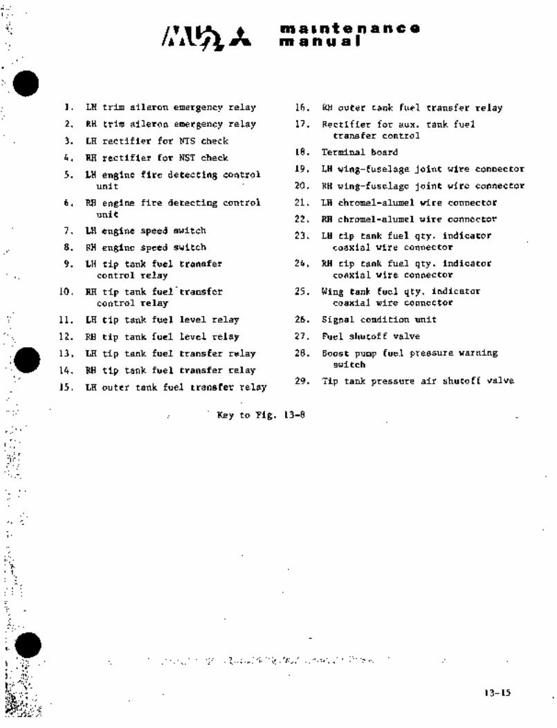
F´•´•´•
v~´•1I
~sA nl a at a a a a a a
m a a a a I
i, LH trim aileron emergency relay. 16, ’RHouter tank fuel transfer relay
2, RH trim aileron emergency relay 17, Rectifier for aux, tank fuel
transfer control3, LH rectifier for NTS check
4. RH rectifier for NST check 18. Terminal board
19, LH wing-fuselage joint wire connector5, LH engine fire detecting control
unit 20, RH wing-fuselage joint wire connector
.6. RH engine fire. detecting control 21, LH chromel-alumel wire connector
unit22, RH chromel-alumel wire connector
7. LH engine speed switch 2j~ LH tip tank fuel qty. indicator
8, RH ´•engine speed switch coaxial wire connector
9, LH tip tank fueltransfer 24, RH tip tank fuel qty, indicator
’control’ relay coaxial wire connector
10, RH tip tank fuel transfer 25. W~rig tank fuel qty, indicator
control relay coaxial wire connector
11, LH tip tank fuel level relay 26, Signal‘condition uni.t
12, RH tip tank fuel level relay 37 Fuel shutoff valveLI.
13, LH tip tankfuel transfer relay 28, Boost pump fuel pressure warningswitch
14, RH´•tip tank fuel transfer’relay29, Tip tank pressure air shutoff valve
15, LH outer tank fuel transPer.relay
Key to Flg, 13-8
´•1´•:":
c,;
i.. :J
Bi: g,;i ´•c~
13-15P´•

a i k% e.lP a pit a a
ni a a a a I
ORIGINALAs Received By
AT P
12 1 13
1
Fig. 13-9 Electrical. system in center wing trailing edge
13-16 1

c~s m a II nit a a a ~i a a
m a n a a I
i. Flap motor 7. RH oil cooler air intake
2; Flap up relayheater indication light fuse
8. Flap pulse drive delay relay3. Flap down relay9. Flap pulse drive control relay4. LH oil cooler air intake
heater contrdl- relay .10.~ Flap 200 control relay
RH oil coblerair intake 11. Stall warning system flaphii~ter control relay position transmitter
6. LH oil cooler air intake 12. Terminal-starter generator wiring,heater indication light Fjing-fuselage jointfuse
13. Starter generator wiring
Key to Fig. 13-9
13il´•7’

ni ii ii ~i t a in ii a
an a a a a I
20
´•r;’:
2132 31
7s
24
’30 ’m Im II ,2348
29
II I35
m38
=111 28 4041 39
27 37
3626 4344 45 A
1 ~s 2118- I i ~a I -9
5\; -104
19 ~n -~65) I t-rt~ 1 I \\\\i 11 ‘3
Q47 14
12 846 1315
I i i50
53
1749
16
54
51
52
Fig. 13-10 Main junction box
13-18

It IIIaI at 8 19 a a a a
m a a or a I
i. LH starter auxiliary relay 27. LH starter relay
2. RN starter auxiliary relay 28. RH feeder relay
3. LH ignition relay 29. LH feeder relay
4. IU´•I Ignitrlon relay 30. ItM I:cctlcr c,vt~rload ~:ciisor
5. LH start select relay 31. LH feeder overload sensor
6. RH start select relay 32. L R main bus tie circuit
breaker7. External power control relay
33. Series paralleling relay8. Engine start control relay34. Series parallel control relay9. Landing gear safety relay35. Monitored bus control relay10. Air conditioning room temp.
auto-control relay 36. RH voltage regulator
11. ’Air conditioning room temp. 37. LH voltage regulatormanual-control relay
38. RH overvoltage relay12. Flap delay relay
39. LH overvoltage relay13. Flap takeoff position
40. RH voltage regulator controlcontrol relay
relay14. Flap pulse drive control
41. LH voltage regulator controlrelay
relayi 15. Fuel low level relay42. Voltage detector adjusting
16. Main inverter relay resistor
17. Converter relay 43. Voltage detectdr adjustingtest terminal
18. Inverter failure detectingrelay 44. RH generator voltage adjusting
test terminal19. Instrument power exchange
relay 45. LH generator voltage adjustingtest terminal
20. Circuit breaker panel46. Voltage detector
21. Signal summing unit
47. Voltage detector condenser22. RH reverse current cutout
relay 48. Inverters
23. LH reverse current cutout 49. Strobe light power supplyrelay
50. Main inverter diodes24. RH shunt
51. Standby inverter relay25. LH shunt
52. Standby inverter diodes26. RH starter relay
53. Inverter select relay
54. Cabin lighting relay
Key to Fig. 13-10
13-19

It HI118lntenancena a a a a I
1.3 UIXING a1.3.1 GENERAL DESCRIPTION
Wire bundles in the airplane are routed as follows: Wiring from each
system in the forward fuselage passes through the forward pressure
bulkhead, and is connected to the connection box on the lower front
of the instrument panel. Wire bundles from the instrument panelsand switch panels and wiring around the cockpit are concentrated and
connected together in the connection box. Wiring between the connec-
tion box, annunciator panel, circuit breaker panel, bulge, left
upper switch panel and LH wing leading edge disconnect plug is made
through LH side panel. Wiring between the connection box, right
upper switch panel, RH wing leading edge, main junction box and aft
fuselage is made through RH side panel. Wiring for engine and
propeller control, wing tip light and fuel control is connected to
LH and RH disconnect plug in front of the center wing through wingleading edge. Wiring between the starter generator and main junctionbox passes through the wing trailing edge, center wing rear section and
aft passenger compartment ceiling. Feeder is distributed from the
main junction box to the circuit breaker panel through the aft
passenger compartment ceiling and LH side panel.
1.3.2 WIRING IDENTIFICATION
MARKING
(IWire identification markings are
stamped on all wires throughoutthe airplane. These identification
markings consist of a circuit
function letter which shows
system to which it belongs, a r-´•´•--- ~j\.lllbol for CirCUit functionswire number, a segment letter I-´• Wi z´•e nurrtb er
provided for each wiring block r- Segment letter
and a wire size number. Wire size
Grounding symbol
6~0 O<T ct lfj‘~ E3 20 N
4-1-7813-20

clr~ It 111 11 Int e n zf 11 c e
101 8111~1s
CIRCUIT FUNCTION CODES
CIRCUIT CIRCUIT FUNCTION/SYSTEM CIRCUIT CIRCUIT FUNCTION/SYSTEMFUNCTION FUNCTIONCODE CODE
C flight Controls M Miscellaneous Electric
Ct Flap Control M1 Windshield Wiper Control
62 Trim Aileron Control M2 Toi letM3 Cigar Lighter
CW Control WheelP DC Power
D Instruments (Except Flight and Engine) P1 DC Power
Dt O.A.T., Outside Air Temperature P2 DC Power
03 Trim Alleron Position Indication P5 DC Power
E Engine Instruments Q Fuel and Oil
Et Engine Instruments Q1 Main Tank Fuel Control
52 Fuel quantity 42 Fuel Transfer Control
43 Fuel Transfer Control
F- Flight InstrumentsFt Turn and Bank Indication Y DC Power and DC Control for AC
F3 Pitot and Static Port Anti-Ice V1 AC Power SourceV2 AC Power Source
G Landing Gear
61 Landing Gear Control X AC Power
61 Landing Gear Position Indication X1 AC Power Source
X2 AC Power Source
H Heating, Cooling and Anti-Ice
Ht Engine Anti-Ice, Propeller De-Ice Warning and Emergency (Master Caution)H2 Wing De-Ice W1 Vacuum Pressure Warn
H3 Air Conditioning W2 Door Lock Warn, Master Caution
H4 Door Seal W3 Fuel Pressure Indication/WarnH5 Heated Windshield Anti-Ice \54 Stall.Warn
H6 Oil Cooler Inlet Anti-Ice W5 Engine -Fire Detect
H6 Engine Fire Detect
K Engine and Propeller Control W8 Fuel Filter Bypass/Boost Pump Failure
11 Engine and Propeller Control W9 Cabin Pressure Warn
#2 Engine and Propeller Control W20 Battery OvertempK7 Propeller Synchrophaser W21 Defog OvertempK9 Propeller~Synchrophaser
BT Battery OvertempL Lighting FPM Fuel Pressure Meter
Lt Navigation Lights OC Oil Cooler
L2 Fuselage’Landing Lights HHS Heated WindshieldL3 Room Lights TTL Tip Tank Light (Taxi)L4 Instrument and Switch Panel Lights P PowerL5 Trim Indication LightsL6 Instrument LightsL7 Strobe LightsL8 Tip Tank Taxi Lights
4-1-7813-21

c~3 It m a a a a I
1. 3. 3 VrlRE SPECIFICATIONS
Wires in the airplane have been selected according to the current and nature of the
circuit and installation in the airplane. When the wire is replaced, wire of the
same type and size should be used. General policies covering the wire selection
are as follows.
Specification Use
MIL-W-5086 Type II General airplane wiring
’MIL-Mr-8777 (MS27110) Wiring within engine nacelle
MIL-W-5846 Type II Wiring for engine exhaust gas temperature
thermocouple
ML-~-7078 Type n Wiring required for static shielding
M3L-C-17/78 Type Fuel quantity indicating circuits
RG-187/U
Mitsubishi Specification Wiring in flap sliding section of aileron
M9013 trim system and cockpit connection box
QMitsubishi Specification Wiring required for static shielding in
M9007 M9014 engine nacelie
13-22
malntenane a
m a, nual
a 1.4. TNSPBCTION O~ eLBCTRTCIY´• SUSTM
Inspection and preventive maintenance of the electricalsystem should be
accomplished, thereby minimizing probability of failure.
(1) Cheakthe wiring for fuel or oil contamination.
(2) Check all terminal blocks for loose connections. Check adjacent terminals for
contact and for short circuits due tB foreign matei´•ial.
(3) Check all units for security of installation.
Check wiring for security and fo~r evidence of overheating or damage.
(4) Check all bonding for positive installation electrically and freedom from
corrosion.
(5) dheck´•operation of each system.
NOTE
Electrical bondingis required for safe and steady flow
of load current,~preventing radio noise frbm occuring,
and for protectingthe airplane from lightning.
i. 5 TROUBLE SHOOTING FOR ELECTRICAL SYSTEM
1. 5. 1 PROCEDURES FOR TROUBLE SHOOTING
Trouble shooting the electrical system can be accomplished in many ways.
The following is an example of a practical an~ rapid trouble shooting method.
Trouble after 50 hours of service is mostly due to defects of individual parts or
units rather than defective wiring. Therefore such items should be checked
before checking wiring.
(1) Referring to wiring~diagram, defermine that there is specifiedvoltagebetween terminals.
(2) If a unit involved does not operate~though there is voltage between terminals,
check grounding and bonding. If normal, replace the unit.
(3) If there is´•no voltage between teimin~ls: check circuit breaker, fusegandswitches
(4) If voltage is’ still absent between terminals, finally check the wiring.For continuity checki: disconnect all power sources ak;d disconr-´•:ct plug for~
system which is´•being
airfranie structure and for leakage ~through insulation.
Check continuity between plugs, ´•wiring for contai~t with other wiring or
13-23(24)

.--i. r. C.i.
R t 8.HIa.´•1.,- h a .e
u c~ a I
Dd POWER S~PPLfi SPST$~
2.1 GENERAL i)ESCRIPTiON (See Fig. 13-11)
In the DC p~r supply system, two batteries ate provided in order to
~acilitate englrie;st8rtiig. ~hiB systein 16 op6i~at;ed as follows. When
the batt’ery Itefi bt7itc3h and battery switch d´•n the LH subipaiiei are turned
to ON and the series patallel switch is in pararlelj the two batteries
are in paraliel-tothe DC power. Syst~em. If the engine statt
switch on the center pedestal siSitch panel is pushed ´•down ~ith the
battery selectdr switch inparallel position, thebatteries are connected
in parallel to the stak´•ter and engine start.
If the engine start switch is pushed down with the battery selector
switch the batt’p~ies are automaticai~f connected
in series arid~engine start´•i ~enan engine reachi~s about
56% of RPM and starting cdmpletes, the batteries return to a parallelconnectionwith the Dd.pdwe.r system; The’ignitors, fuel:shutof~ valve,
speed switch and inverter get st~trer bus dining engine
starting. Since tl~e’ voltage of the starter bus exceeds 30Vsometimes
in battei~yseries: startipgi-´•:the: ~ltage detedtbu .is. instglled ´•ip the main-
junction box:. When the vditlage exceeds 29V, the´•power source.iS auto-
maticaliy turned to the mciin bus to protect ignitor and inverter from
overvoltage.
When the generator:controi -srjitch DC GEN- on the LH switch panel is turned
to ON´•afterjs~ayting engines;: LH generators are connected to the
main bus..respectively .through the reverse curr~nt cutout relay. The
MASTER switch is used to cut off ail power soitrces in case of emergency,such as anelectrical fire.-
controlled at´•: i8.5Vi: by the voltage regulator. InGenerator voltage Is
order to balanci! load current to t~o gerierators, voltage drop of generator
groundwinding is utilized. This voltagecontrols the generatorthrougha voltage regulator so that the:difference in current load of both
generators --is--kep:t- -~o-´• a-:-m´•i-n-i;mums-- pro tect-e-l-ectricaaf
unusually high ´•voltage of the generator, an overvoltage relay is pro-
vided in the main junction.box; When a generator--involves high voltage
due to failure, the- relay: automatically disconnects the´• generator from
the aircraft electrical bus. ´•To´•restore the-generator to normal opera-
tion, mbmentarlly:turn ~tfie. generator cbntrol switch from QFF~ to RESET:
position and return´• tq 0~ position..; L~hme’ter shunt of:Sqmv/3QOA rating.´•
showsthe current load on the LH switch panel ´•anrmeter. When;the generator
voltage becomes lower thnthe voltage.in the´•´•main:junction box
due.to failure df= vi~ltagelregulator Br gkrierator.ciruit and a reverse
current of 9 to 25A is genera’ted, the reversecurrent relay opens, dis-
connecting a generator from the main bus.
When the generator voltage increases, the relay closes, connecting the
generator to the bus.´• The nickel’cadmium battery.will´•: withstand the
high charging current.~at the. Sniriai. .s-tage of_charging, depending on
j discharged condition. ’The charging rate usuarIy~ exceeds 300A after an
engine is started by battery. Thb..chargirig ´•rate decreases gradually as
time elapses and usually,ecomes lessthan´•50A ina fewminutes.
13-25

C;tll8 i tP n -a n aI:,
iin a-ii pu ii I
d B
ula ~lidul BBEEn 1,1 oui g,
Isoalr 6
Ixv~ -J 515 t~ i:iP::l a’~ 5:
"P a
1- P"""5~ss dj
wslr rlev~ rrsis wiarj a Pa
a-rr ep d
a yr
JB i
idE´• f
I
E8 I wr
uXZ’
5 4
s~aeE
iir:
B le;~B PB5 a Bn ta CP~ I Ri 5 t s
C elbl a Had B H IHH d~HHSB 1 ~g
s E
g y/ed n
a 5 ti
Y c
n a B I na 2 a B 5
a r H 154Hu S" a 5 a Y
a dm i-Z~P p.
B i"I aru t5so
:r 1 i 5a,-rz ’B
I 6:8 ti: 8:e~9’ u 2"e3~ 5
5
1 5 o aB r J5 "Z 35 S;i
Ir
E8e a a e Y 6 ~(P BY I
ilndiiia
2gp Sa
od
S Bs h
5$ ~6 PS r5 I 5
f 5s s 5 5 5
,t!N N
Irlrs lolli 1fH-
a311115 O 10116
Si: 3i-)0 dOld E I331-30 tart 1 S
uH"I;;~lxvirl eu~
3rviul sH3 1 in131NI 13~003´•
11D
i’ ii s 1. rii.,
113WI 833003 l10
´•5 8tRlb
~Puxr
ib Ig9
Flg.´•13-11 PaJer distribution (1/4)(Typical S/N 652S, 661SAI 697SA~thru:713SA)
L3-26

´•"´•I
W FEEO~R IUI REEOER ImERTER
rO LH EP CONTROL REL~’I I I IF41L IT I,I
I I 1 10 EH iYG LOh:i~Oi(W1+R SY XEI SY
CISCV!I BREIYEr( nOPI OH REUI CIRCUIT BREUER bI
´•e
OC 6E1l conr s~Rr I BImR1 STIRT SELECT SY s~mrtr SELECT su I~rarra
Or ul IM callpz luln
PI r´• MI M OI(ICII SERIES
IIROFF UIN
~YFEI I BUSS TIE
Cn r I IW E116 STlr(T RESET I TRESET JOPF 578111 RHEHGPU~LLR
r:
o\rc,
avorrocr VOLTK´•E TIh) vnnwcn ~d REU* REQLUTOR
rruma I I I I I I larvrarr LI II LI I~arriarr
~SUUIOI
Cb I I\sEmRaroa CURRENT CURRENT
M~TER*ISOL
(16PEADLTS D~P
COHYER~ER
bEIIERLTORSLTT ~UT-OUT tUT-OUT 33
a\rPI 101 RTLII
a-a
PI PI)i" m~ ~lp II
rl SER REU\’IBA~ER(M1 8*Ti SERIES I
AUX Rn~ n
~o d 51611
~e Isa puR CM II, REcm"II III i I ’rC
Cn rr REUI
O
EXRIi,p ac, aa~ PI(P
I i RIRnP SERIEI,
paRuL
rH STIRT I(fU1 tOHYERTERREUI I
9)e h) RLUII I --I n I I I I I I COHYERTER
o olsraRrconr
~´•f aoa~r
4YEa CONTW1
tn I I I IW STIRT~OIIITOIIEO
YOLTI\6ERrur
svs (bIl I t I I I I I ISENSORIEL~
I
AUX HELII
Lil ST~RT IW fTllli
IUX IIEUI
UI s;aR1:) Il rw STIRi
SE;LCT r) 1; SELECT
uinr II RELPII
C-’
W
h)
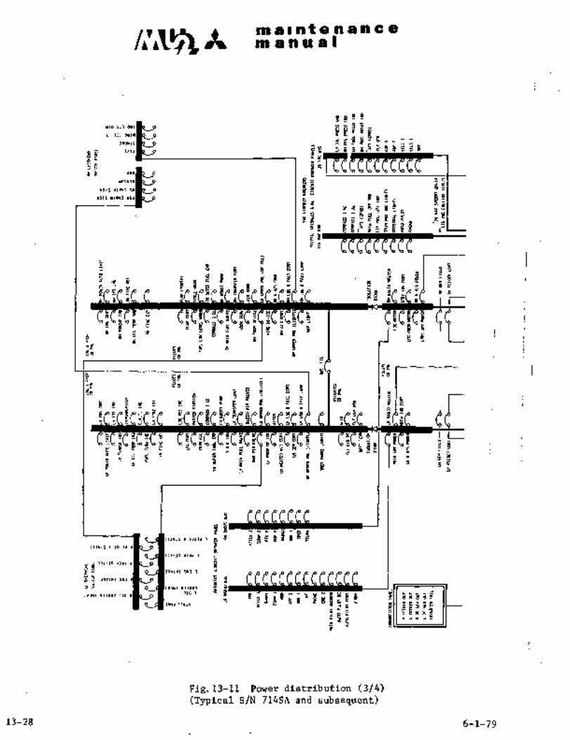
ma~ntenancean an u a I
8888
ria sn awi a B13 1,1 owl
Ilr~ 5 5 5 8.6 i gS~?S
eae K dvw~gCp6pezpC9P~ Y
Ho~vla le z~
YI)IS U1813 SYa O 1 a,U e%%H91S UIBY) 8SJ
Y
d
i i, C iuP de
n
~5’88 8E g e
´•n 4: i8 S
d
s"g
2 B 16
0858 5~P
S 3~ 5 B IJJB~ BL, H HL~ sh H\n ~\o st, HL~ H\n H\n =ii aE ~b. I I
8
diI, E B
sPS a a ffEga
Yl~a8
P g t f aH ,8~P´• B 3 5 1!H 18
Ed H~91 ~e, 8
rt iS
~d f~s
,8 HT.a 6 d 13 f 8
8a~ a
P ti g ;ag
68J
g Is 1388~He aBrE B Y
9L, S\n k \a o\o 5 P 5 s 5 C s 5 .5
E EP~ n ""5 a "8. L_ i
I"e II t j "Es~., s~g ipi´•~"
j 51
5
31 "8
I I
~5 8
5 .5h I 55 4 1 5
$BNNN
~ivis 1 ioiri 1
,Ilvlr i lolla 5
~-la doa~ 3
331-30 a Bjr5 311181 913 1
BE aYIWI BYllk OIJa 4 8
338 I 13100)
P rIr 8~65~lo 1 N
LI1HI 13300) 110 a
5 1~C; ~P 8luah 5 "a~ e5ic rxu
Fig.l3-ll Powerdistribu~ion (3/4)(Typical S/N 714SA and subsequent)
13-28 6-1-79

_I__
__
UI;EEDER I JB(ltEEOERJI Jl)lY19T~I16 iYi (Oa:l:~
LEIW IELI rR!LRI~I\1
mucEncconnmL
IIFF flarur I CIRCUIT BBUER
~IRr gRCIRCUIT BREII(ER
II
EICPBLTTal SRECT 91
Ulwxr,rltnaar sELEcr zu
~111101102sraa7 1´• rnlr
I;stlss r !1
a sysrll S%EIR~
rCNC 4rT 9iSrUt paa*ILa
OC~3 II I II I I I/YOLT/VOLTIG( OY~)VOLT
P´•cos ~--i-P, YOLTIGE
arPaaoa RELIIi
r
snarrre
RE~u\ma
orurasECURRENT 6EWE~lllmR
ITlRTERREVERSE
V1 CURRE.I CUT-OUTsnmuma
Z’da*rrolr i
e~rr CUT-CUT
~so: ate o;Poe-a
333
ppppr
:0;9 I,c- a C16
i ’ER RcuIIV1 I
~tanut rua rl
Bm 516*
Bmrtm I
i: au*1’ REcm
Isu I RaI ncr I I I I I I´•"
V, d I I pua I fI ’~71h/ P):Drt icEmr
sEEm Rnav
SERIESL-
c~ PIWI~ Raba IImsr~ar anar
.V1arur
CoNr 0).(D
8" 1c.
rrmlronror+~ w sraar va! 7J~GL
‘REUI StNSOI)SVS
V ar~r
do
11aal
~LLIiJ- ,,:~1
an sr4a-r;rar
(Ihiiii:SLIL:T
a;nr i] i’ Rar´•
i
rw
P3rD

´•H~i i~ bi Q’I
E.i. DC
the uppea side bf the engine gearThe ib.lnscall´•ea on
box. .T~i’e ge~erator i~couplrd to the eiigine.fotoie wit;ha gear ratio of
1:;o.261i Excitation bf- the field iif the generatof is by shunt and
voltage is 28.15V by a 3oltdge regulator in´•engine flightidle condition. .The genetator is cdoled by a built-in cooling fan and
by cooling air firom a scoop dn the nacelle outer $kin.
2.2.1 REMOVAL
(1) 2 hds~s from oil line leading to oil cooler’.
(2) Remove electric connector (P4001) froniwing leading edge.
Remove hoses of fuel.line~ ftom wing leading edge (RH only).
(4) Remove 2.oiI hoses of engine torque pressure line -from engine.
(5) Remove wiring from terminal block of. generator. Attach ident~ifi-
cation marks to each Gire to’ facilitate reinstallation;
(6) Unclamp:Marman clamp. Remove generator from enginemounting pad.
(7) Remove -nuts from engine-mounting pad, if necessary.
N’O TE
Care: sho;uld´•be taken.:nor;to´•have
prote’cti:ng cage oe~cooling fan
deformed whei~’ removing generator.
2.2.2 INS~ALLATION See Fig. 13-2)
(1) M~unt generator in accordance with 3 guide ´•pins on brack~t of
enginP mounting pad. Clamp with´•Marman clamp. Tighten 6 nuts
to 120 to 130 in-lbs. (137to 149.kg/cm) for attaching bracket
to engine mount. on oneof the boltsattachingbracket together with ground wire from terminal block E of
generator. Tighten’Marma’n clamp to a torque value of approxi-mately 56 in-lbs. (58 kg/cm).
(2) Connect wir~s securely to each terminal of terminal block of
generator.
(3) Connect 2 hOSCs 01 L’ngine torque preaeure line.
(4) Cbnnect 2 hbse~.of oil line leading to oil cooler.
(5) Connect hose~of fuel,line (RH only);
(´•6), Connect electricconnector (P4001).
13-50

c~r Itmaintenanceman ual
Guide pinBracket
Ground strap ´•wire
(016B-88424)Connect to
"E" terminal
Rotor coupling Bolt
K51A20 3iK56A20
~IGround strap wire
(016B-88424) P12A16
(for vol.reg.)P10A16
(for field magnet) PllA16
B (for vol.reg.)
u0 C P3h3
~for starter)
P2AO
A/C S/N 652SA only I (for generator)
P4AONFig.13-12 Wiring of M: Generator
Spring Brush
n\ approx. 0.71in.
Position "a"
BrushBrush
Commutator groove
Fig.13-13 Generator brush
3-31-90 13-31

ma~ntenancem a a a a I
2.2.3 INSPECTION (See Pig. 13-13)
(1) Open nacelle cover and check wiring for security of attachment to
corresponding terminals.
(2) Check brushes for position and smooth operation in guide fixtures.
Check for excessive play, cracks or damage. If brush measures
less than point "a" of Fig. 13-13, it should be replaced with a
new one.
(3) Check surface of coIIIlnutator´•foror cleanliness and freedom from
grease or other fluids. Blow off carbon powder by dry pressure
air.
2.3 VOLTAGE REGULATOR
The voltage regulator is installed in the main junction box and maintains
power source voltage 28.5V regardless of loaaedcurrent. This voltageregulation is accomplished automatically,changing exciting current in
the generator field coil. In additionto thevoltage regulating circuit,the load current equalizing circuit is provided. This circuit equalizesthe load current of the two generators by changing the generator outputvoltage.
2.4 REVERSE CURRENT CUTOUT RELAY
It(ro differential type reverse current cutout relays are installed in the
main junction box. These relays connect the generators ´•to the main bus
when the generator switch is turned to ON. Under this condition, load
current should be flowing in the circuit and generator voltage should be
higher than main bus voltage by 0.35’ to 0.65V. If generator voltageshould decrease and 9 to 25A of the reverse current flows through the
relay, the generator is disconnected from the main bus. At the same time,an auxiliary contact of the relay closes, illuminating L(R) DC GEN OUT
on the annunciatorpanel,
2.5 OVERVOLTAGE PROTECTING RELAY
The overvoltage protecting relay is installed in the main junction box.
This relay protects equipment from high voltage of the generator by auto-
matically cutting off generator output from the main bus, if the generatorhappens to generate unusually high voltage. The circuit can be restored
to the original condition by the generator switch turned to RESET from
OFF, then returned to ON. Trip voltage of this relay is 32 to 34V.
2.6 VOLTAGE SENSING UNIT
The voltage sensing unit is installed on the inside of the relay box in
the main junction box. When the voltage of starter bus exceeds 29V while
starting engine, the sensing unit actuates the monitored bus control relayto disconnect the monitored bus and the inverter from the starter bus.
13-32

ao a i at a a a a a a
Itn a a a a s
a ;.I CHECKOUT AND ADJUSTMENT OF DC POWER SYSTEM’
Voltage adjustment and parallel operation adjustment should be performedwhen generator or voltage regulator is replaced.
2.7.1 VOLTAGE ADJUSTMENT
(1) ´•Close the circuit breakers of engine control, DC power, AC power,
engine instriiment ai~d fuel control~systems on the ci~cuit breaker
panelin cockpit and the’main junctionbox.
(2)’ Perform engine warm up more than 2 min. with 96% RPM operation.
~’3) Hold battery switch and battery.key switch in ON positions.
(4) Turn the left and right generator switchesin LH switch panelto OFF.
(5) Connect the terminal GEN of LH reverse current cutout relay in the
main junction’box to terminal of an accurate voltmeter (30VDCClass 0.5) and"-" terminal to the airframe for ground.
(6) Turn the left generator switch to ON.
Turn the adjusting screw of voltage regulator slowly with a
screw driver (clockwise to increase voltage, counterclockwise to
reduce voltage) and adjus:t the vol~meter´•to read 28.58.
(8) Turn the left generator switch to OFF.
(9) Connect the terminal GEN of RH reverse current cutout relay in
the main junctfonbox’to terminal ofthetoltmeter and
terminal to the airframe forground.
(10) Turn the.right generator switch to ON.
(11) Turnthe adjusting screw of voltage regulator slowly with a screw
driver’andadjust the’voltmeter to read 28.5V.
‘(12) Turn the right generator switch to OFF.
NOTE
Ensure no fluctuation in voltagein five minutes operation of
engine afteradjustment.
13-33

manual
2.7.2 PARALLEL OPERATION ADJUSTMENT
Equalizeload current of LH and RH generators in the following manner
after voltage adjustment is performed in accordance with Para. 2.7.1.
(1) Close circuit breaker MASTER CAUTION.
(2) To conduct tie in test of LH generator, turn right generatorswitch to ON. R DC GEN OUT on annunciator goes off.
(3) Turn left generator switch to ON. L DC GEN OUT on annunciator
panel.goes off.
(4) Turn left generator switch to OFF. L DC GEN OUT on annunciator
panel.´• illuminates.
(5) Turn left generator switch on and off repeatedly, and verifyL DC GEN OUT going off and illuminating.
(6) To conduct tie in test of RH generator, turn left generator switch
to ON. L DC GEN OUT on annunciator panel goes off.
(7)- Turn right generator switch to ON. R DC GEN OUT on annunciator
panel goes~off.
(8) Turn right generator swi~tch to OFF. R DC GEN OUT on annunciator
panel ~illuminates.
(9) Turn right generator switch on and off repeatedly, and verifyR DC GEN OUT going off and illuminating.
:(10) To conduct tie in tests of LH and RH generators simultaneously,turn left generator and right generator switches ON or OFF
simultaneously. L and R DC GEN OUT on annunciator panel simul-
taireous’ly go off or illuminate, respectively.
13-346-1-79

A maintenancem anual
Na TE
(i) Apply 20 to 40A load to generator for
performing parallel operation adjustmentsof generator. It is recommended to
operate inverter,nding lights,anti-collision lights and cabin lights.
(ii) If the test under load does not result
in proper tie in, that is, L DC GEN OUT
on’annunciator panel does not go off
with left generator switch ON or R DC
GEN OUT illuminates with the switch OFF,the output voltage must be regulated bymeans of voltage regulator. Turn voltageregulator adjusting knob for generatorwith greater current slightly counterclock-
wise; fordecreasing output voltage, turn
the opposite regulator knob slightlyclockwise forbalancing. Confirm that
voltage measured at main bus in the
main junctionboxis 28 to 28.5V.
2.7.3 OPERATIONAL CHECK OF VOLT-AMMETER
After conducting parallel operation adjustment of LH and RH generatorsunder engine operation~at constant speed, perform operational check ofvolt-anrmeters in accordance with the following procedures with leftgenerator and right generator switches concurrently in tie in condition.
(1) LH and RH volt-ammeters must read about 28V.
(2) To perform "O" load check, circuit breakers OFF exceptMAIN INV POWER, MAIN INV CONT, LH ITT IND, RH ITT IND, LH FIRE DET,RH FIRE DET, LH GEN CONT and RH GEN CONT in cockpit circuit breakerpanel and LH GEN FIELD and RH GEN FIELD in the main junction boxcircuit breaker panel, and turn battery switchOFF to makeelectrical load to O. (ref. value). LH and RH volt-anrmeters shouldread zero (ref. value).
(3) To perform load check, operate inverter, landing light, anti-col-lision light and cabin lights to an-aggregate load of about 50A.The differential amperage between‘LH and RH volt-ammeters shouldbe less than 5A (half graduation).
13-35

c~s Itmaintenancemanual
2.7.4 CHECKOUT OF VOLTAGE VARIATION
(1) When "O" load check is performed (see Para. 2.7.3), set engine RPM
to 100% and operate inverter, illuminate landing lights, anti-col-lision light and cabin lights to give a load of about 50A.
(2) Set engine RPM to 65% (~1), 75% (*2) and operate inverter, illuminate
landing lights, anti-collision light and cabin lights to give a
load of about 50A.
(3) Make sure that voltage variation in the above tests should be
-1.0 to +0.5V.
*1 Aircraft S/N 652SA
*2 Aircraft S/N 661SA, 697SA and subsequent
2.7.5 OPERATIONAL CHECK OF OVERVOLTAGE RELAY
When the generator, voltage regulator and overvoltage relay are
replaced, voltage adjustment, parallel operation adjustment and
operational check of the overvoltage relay must be checked.
2.7.5.1 PREPARATION
(1) Connect overvoltage tester to LH and RH voltage regulators.(See Fig. 13-14)(a) Remove wires (P141D20 and P101D20) connecting to
terminal "G" of reverse current circuit breaker and
connect the overvoltage tester between the above wires
and terminal "G" as shown below.
(b) Turn tester field rheostat RF1 and RF2 counterclockwise
fully and set to "0" ohm.
"C" L. ii. reverse current "G" R. H. reverse current
circuit breaker circuit breaker
L.H. Voltage R.H. VoltageB B
Regulator Regulatora I I I lacu IcJC1 C~
r(
laI~
Pc In
k-WIL~ ~-RHGi9LHG RHI;
I I 0, Over Voltage tester
(See Fig.13-14A)DC Voltmeter (50V)
Fig. 13-14 Connection of overvoltage tester
13-36 3-31-90

maintenancemanual
1) (2
I~RF-
RF-
5)(RED)
6)(BLACK)
O Wire, MIL-W-5086/2 AWG #18 or equivalent
O Terminal lug, MS25036-6 or equivalent
O Toggle switch(ls), SPDT type commercially available
Variable resister, 0 350 ohms 3 watts ratingcommercially available
O Insulated red banana jack, commercially available
Insulated black banana jack, conrmercially available
Fig 13-14A Schematic wiring diagram for overvoltage tester
3-31-90 13-36-1/13-36-2

c~its m re a t a a rp’n i= a
m a a a al
(2) Perform engine warm up more than 2 min, with 96% RPM.
(3) Turn battery switch´•and battery L$y´•switchON.
(4) Close LH ENG FIRE DET, ´•RH ENG FIRE DET,LH GEN’ FIELD, II~I GEN FIELD, LH and RH GEN CONT.
Open other. circuit ´•breakers.
(5) Adjust output´•volt‘age df~LH and RH~ generators to 28.5 ´•f 0.5V
Of tester by -means of resistors ~RF1 and RFE.
NOTE
When the circuit breakers are turned off in accordance
with paragraph (4)-above with the engine inop’eration at
a constant: speed, only the tachometer will remain in opera-
tion. Use cautiqnwhen operating´• theengine in this condition.
i.7.5.2´• OPERATIONAL CHECK OF LHOVERVOLTAGE. RELAY
(1) ´•To check operation of LH’overvoltage relay, place~ selector
switch of volt-ammeter of tester in LH posit’ion, and
volt-ammeter indicates voltage of LHgenerator.
(2) Turn left DC GEN and-right DC GEN switches simultaneouslyON.
(3) Watching volt-ammeter reading, gently turn RF1 clockwise to
reduce excitation~resistance and gradually raise’voltage. The
´•rlsing voltage drops from 32V to 34V to 3V dr less in about
2 secondse
N,OTE
(i) Never raise voltage to 35V or higher.
(ii) Raise’voltage to 30V at a rate of about 1V/~ec.,and in excess of 30V atla rate of about 0.2V/sec.
(iii) Somet’imes,the: voltage indicator of the volt-ammeter
in the aircraft may scale over. ‘The voit-ammeter
is well capable of withstanding overvoltage of
..JZ´•-..td 34‘v.’
(4) Reset left DC ~GEN swifch with LH overvoltage relay tripped.Verify that overvoltage relay is´•re-energized, andgeneratoris not reset.
NOT: O
When: ~relay is reset, the volt-ammeter
I
indicates: approximatell 28V, When. the overvoltage relayis not reset~, the ir6lt-andmet’er inhicates. below. 3vl
13-37

ar g i nt e.h a in 8
ni a in ill a
(5) Place left jbC (;EN DC GEN swi~ches iri OFF position.
(6) ket~irn RF1 fully to driginal position.
(7) Place left DC GEN switch alone in RESET position and turn off.
(8) Adjtist output voltage of LH genetator to 28.5V by means of RF1.
2.7.5.3 OPERATIONAL CHECK OF RH OVERVOLTAGE RELAY
(1) To check operation of RH overvoltage relay, place selector
switch of volt-armneter of tester in RH position, and
volt-anrmeter indicates voltage of RH generator.
(2) Turn left DC CEN and right DC GEN switches simultaneously ON.
(3) Watching volt-ammeter reading, gently turn RF2 clockwise
gradually to raise voltage. The rising voltage drops from
32V to 34V to 3Vorless in about 2 seconds.
NOT IE
Never raise voltageto 35V or higher.
(4) R~set right DC GEN switch with RH overvoltage relay tripped.
(5) Place right DC GEN and left DC GEN switches in OFF position.
(6) Return RF2 fully counterclockwise to original position.
(7) Place right DC GEN switch alone in RESET position and turn OFF.
(8) Adjust output voltage of RH generator to 28.5V by means of RF2.
2.7.5.4 OPERATIONAL CHECK OF MASTER SWITCH
(1) Turn master switch on LH switch panel in cockpit upward.Battery relay is de-energized. Overvoltage relay trips.Volt-ammeter in the aircraft indicates zero volts.
(2) Turn the master switch downward.
(3) Place left generator and right generator switches in RESET
position, and turn on. Volt-anrmeter in the aircraft indicates
approximately 28V.
(4) After all operational checks are completed, close circuit
breakers required for operating engine at constantspeed.
(5) If operation´•of overvoltage relay is found normal after
engine is stopped, disconnect testers from LH and RH voltage~egulators. Restore wiring to original condition.
13-38

C~jS m a Ilntenance~m a a a a I
2.7.6 ADJUSTMENT AND CHECK OF VOLTAGE SENSING UNIT
2.7.6.1 REQUIRED EQUIPMENT
Variable power source DC 20V to 3qV 1 set
M DC Voltmeter O to 50V Class 0.5 1 ea.
DS-1 Light ~S25041-6-3i7 or equivalent 1 ea.
S-l,~´• S-2 Switch:MS35058-23 or equivalent 1 ea.
2.7.6.2 ADJUSTMENT
(1) Set all circuit breakers and switches to OFF.
(2)´• Connect wires as shown in Fig. 13-15.
(3) Turn the adjusting knob of sensing voltage adjusting resistor
(R225) counterclockwlse until it stops.
(4) Turn key switch andbattery switch ON (or connect
external power source).
(5) Set the output voltage of the variable power source to 29V.
(6) Turn the switch S-l ON and ´•turn the knob (R225) clockwise slowlyuntil the lightDS-lcomes on.
(7) When the light DS-1 comes on, lock the adjusting knob.
(8) Turn the switch S-l OFF and set the voltage of the variable
power source to 20V.
(9) Turn the switch S-l ON and raise the voltage of the variable
power source at a rate of about IV/sec.’and make sure that the
light comes on when the voltage com~s to 29 f 0,5V.
(10) ’Repeatsteps(8) and~(9) two or three times.
13-39

m a II at a a a a ic ism a a a a I
2.7.6.3 OPERATTONAL CHECK
To check operation of the voltage detector only, take the followingsteps.
(1) Turn battery key switch and battery switch ON Cor connect
external power Source).
(2) Make sure that the engine start select switch is in the positionof AIR START SAFE.
(3) Set all circuit breakers in the cockpit to OFF.
(4) Connect variable power source, voltmeter M-l, switches S-l and
S-2 and lights DS-1 as shown in Fig. 13-15.
(5) Set the voltage of the variable power source to 24V.
(6) A8certain operation of voltage detector by illumination of lightDS-1 or operating noise of monitored bus control relay when
~switches S-l and S-2 are turned to ON.
(7) Disconnect variable power source, voltmeter M-l, switches S-l
and S-2 and light DS-1.
I POWER CONT
Monitored bus cent. relay
Voltage SensingMonitored bus ITJ-l I Unit Adjustment
p;y~211 Test Jack
[T;T-3 1)3 DS-1
ITJ-5 1 j’ ,52
ITS-61I Variable
6 Power
Source
VoltageSensing iUnit
Fig. 13-15-Adjustment of voltage sensing unit (1/2)
(Aircraft S/N 652SA)
13-40

ms II nte a an a a
nt anual
Monitored bus Mai~hus -1rulollitnrei~
bus control rela\~´• SY- rt bus
G POWER CON?’
Voltage sensingunit
cw f
225
CCWJ
Voltage sensing
i Tj-2 .I ’I’J1-4 ´•1 TJ-(6 .L ´•H´•’ main junction box
unit adjustingre sf sbor
T5-1 T T~ 3 B TJ15 S-2
Earth to airframe
DS-1
MT
S-l
Variable pou´•er source
Fig. 13-15 Adjustment-of voltage sensjng unit (2/2)(8ircraft S/N 661SA, 697SA-and subsequent)
13-41(42)

k in a I nf a h a a a a
Bn a a a a O
2.8 ’I~ROUBLE SHOOTING DC POWER SYSTEM
Trouble Probable cause Remedy
(1)No,l battery is not (a) MASTER switch on LH Set MASTER switch
cbnnected to airplane I switch panel is in up downward.
when battery keyswitch I position.and No. 1 battery Check battery.(b) No. 1 battery has beenswitch are turned ON
discharged or is de-
fective.
(c) Faulty No. 1 battery Replace battery relay.
relay.
(d) Faulty contact of Clean or replace plug.No. 1 battery plug.
(e) Defective battery key Replace switch.
switch, No. 1 batteryswitch or master
switch.
(f) Open diode CR303. I Replace diode.
(g) faulty wiring. Check continuity of wire
and repair it if necessary
(2)No. 2battery is not I (a) MASTER switch is in Set MASTER switch
connected to airplane up position. I downward.
when battery key Check No. 1 battery.(b) No. 1 battery has beenswitch and No. 2
discharge‘d or defec-battery switch are
tive.placed in ON
(c) Faulty No. 2 battery Replace No. 2
I battery relay.
(d) ~.Faulty contact of’ Clean or replaceNo.~ 1´• battery plug. I plug.
(e) Defective battery key Replace switch.
switch, No. 1 batteryswitch ormaster
switch.
(f) Open diode CR303. I Replace diode.
(g) Fusing of fuse F103. i Check wiring ~for
grounding and
replace fuse.
(h) Faulty airplane I Check wiring for con-
wiring. tinuity and repair.
´•13-43

i iiiii iin a ir ii a I
Trouble Probable cause 1 Remedy a’(3)Battery is not dis- (a) Faulty battery key Replace switch.
connectea from air- I switch or batteryplane when battery switch.
key switch or(b) Battery relay is Replace relay.
battery switch isstuck.
placed in OFF
(c) Grounded wire be- Check continuity and
tween battery re- I repair wire.
lay and batterykey switch.
(4)External power can (a) Poor contact of ex- Clean receptacle and
not be connected ternal power I insert power plugreceptacle. securely.
(b) Defective external Replace relay.power relay.
(c) Defective diode Replace diode.
CR301.
Starter does not (a) Faulty starter I Replace starter genera-
(5)
start’ generator. I tor.
(b) Faulty starter Replace relay.relay, start auld-
lial3r relay, start
select relay, L/Gsafety relay or
engine start control
relay.
(c) Faultl engine start Replace switch.
switch, start select
switch, battery se-
lect switch or crank-
run-stop switch.
(d) Malfunction to L/G Readjust timing and
safety switch. I replace if necessary.
(e) Circuit breaker LH(RH) Check wiring for
ENG CONT, ENG POWER I’ grounding and re-
CONT,:ENG START CONT set the circuit:
or LG POS IND have breaker.
tripped
(f) Faulty engine speed Replace engine speedswitch. switch.
(g) Open diode CR205, Replace diode.
CR206.
13-44

m a II at a a d li~ a a
manual-´•i-´•------
Trouble Probable cause Remedy
(5) continued: I (h) Faulty external Replace relay.power controlrelay,series control re-
layerleling relay.(Battery series start
only.)
~i) Circuit breaker SERIES I Check wiring for ground-RELAY have tripped. ing and reset circuit
(Battery series start breaker.
only.)
(j) No. 2 battery has not See Para. (2).been connected to
airplane. (Batteryseries’start only.)
(k) External power can not See Pare. (4).be connected.
(1) Faulty airplane Check continuity and
wiring. I repair.
(6)Starter does not i (a~ No. 1 and No. 2 Check batteries.
accelerate fully I batteries have been
discharged or de-
fective.
~b) Faulty starter.´• I Check starter.
(c) No. 1 or No. 2 1 See Para. (1) and
battery is not (2).connected~to aire
plane.
(d) ’Main bus .tie circuit Check circuit and re-
break~r has tripped. set.
(Battery parallelstart only.)
(7)Starter does not.´• (a) Faulty engine speed Replace engine speed
accelerate -while switch. switch.
starting I (b) Faulty ignitionrelay. Replace relay.
(C) Faulty ignitor. Replace ignitor.
(d) Faulty tachometer Replace-tachometer
generator. generator.
13-45

malntenane a
n, anual
Trouble Probable cause I Remedy
(8)Voltmeter Indicates (a) Faulty monitored Replace relay.more than 29V in bus control relay.engine starting
-(b) Malfunction of Adjust or replace.voltage sensor.
(c) Faulty wiring. Check wiring for
continuity.
(9)L~R) DC GEN OUT on (a) Faulty generator Replace switch.
annunciator panel switch or master
does not go out when I switch.
generator switch is(b) Faulty voltag$~ regu- Replace relay.turned to ON
lator´• control relay.
(c) Faulty overvoltage Replace relay.protecting relay.
(d) Faulty reverse -Replace relay.current cutout relay.
(e) Faulty generator Replace relay.failure defective
relay (S/N 652SA
661SA).
(f) Fusing of generator Check wiring for
failure warning grounding and
fuse (S/N 697SA d replace fuse.
up).
(g) Faulty starter Check generator and
generator. I replace if necessary.
(h) Faulty voltage ad- Adjust voltagejustment. regulator and re-
place if necessary.
(i) Disconnection of Replace rheostat.
rheostat.
(j) Overvoltage pro- Reset by generato~tective relay has switch and turn to
tripped. 0N again.
(k) Circuit breaker Check wiring for
LH~RH) GEN FIELD of I grounding and re-
LH(RH) GEN CONT has I set circuit breaker.
tripped.
Poor contact or dis- Check continuity and
,cdnnecting of air-planewiring.repairif necessary.
’13-46

m a n ii Iiii L iiiit :n a ii a a
Trouble I Prbbable cause Remedy
(10)L(R) DC GEN OUT on (a) Faulty generator Replace switch.
annunciator panel i~ siJi~ch.
not illuminated when(b) Faulty reverse Replace relay.
generator switch iscufrent cutout
turned to OFFrelay
c) Defective warning Replace lamp.
lamp.
(d) FaultL annunciator Replace annunciator
panel. I panel.
(e) Faulty airplane 1 Check wiring for con-
wiring. 1 tinuity and repair.
(11)Load connecti’ng to I taj Faulty feeder. I Check wiring for con-
left and right load bus j tinuity and repair.does hot actuate even
(b) Open diode CR215 or I Replace lamp.if L(R) FEEDER OUT on
CR216.annunciator panelgoes out r (c) Defec´•tive warning Replace lamp.
lamp,
(12)Load 6onnecting to left (a) Fusingof feeder I Check wiring for ground;-and right load bus I failure warning fuse. ing and replace fuse.
actuates even if L(R)(b) Faulty annunciator Replace annunciator
FEEDER OUT onpanel. I panel.
annunciator panelis illuminated I (c) Faulty airplane I Check wiring for con-
wiring. ~C tinuity and repair.
(13).L(R) FEEDER OUT on I(a) Faulty circuit Replace circuit breaker;
annunciator panel is breaker.
illuminated even if cir-(b) Faultyfeeder over- Replace feeder over-
cult breaker L(R) FEEDERload sensor. I load sensor.
CONT is closed
(c)- Faulty feeder relay. Replace relay.
(d~ FuSing of:feeder I Check wiring for ground-failure warning fuse. ing and replace fuse.
(e) Faulty airplane wi’r- I Check’wiring for con-
ing; ’I tinuity and repair.
(14)Load connecting to cock- I (a) Faulty wiring of I Check wiring for con-
pit’ circuit breaker feeder. tinuity.
pan~l bus does not
actuate
13-47

m a a t~ a a a a a a
nl an a a I
Trouble Probable cause Remedy
(15)Voltmeter does not (a) Faulty volt-am- Replace volt-anrmeter.
swing meter.
(b) Fusing of volt- Check wiring for ground-ammeter fuse (F201 ing and replace fuse.
or F203) (onlywhen ammeter also
does not swing).
(c) Circuit breaker ENG Check wiring for ground-POWER CONT has ing and reset.
tripped´• (only when
engine starting).
(d) Faulty starter Replace relay.
auxiliary relay.
(e) Faulty airplane Check wiring for con-
wiring. tinuity and repair.
(16)Ammeter does not (a) Faulty volt-am- Replace volt-armneter.
swing meter.
(b) Fusing of volt-am- Check wiring for ground-meter fuse (F201, ing and replace fuse.
F202, F203 or F204)(voltmeter also
does not swing when
F201 or F203 is
fused).
(c) Faulty shunt. Replace shunt.
(d) Faulty airplane Check wiring for con-
wiring. tinuity and repair.
(17)Indication difference (a) Unbalance of voltage Check wiring for con-
of left and right am- I adjustment of left tinuity and repair.
metersis large in and right generators.
~parallel operation of
left and right genera-
tors
13-48
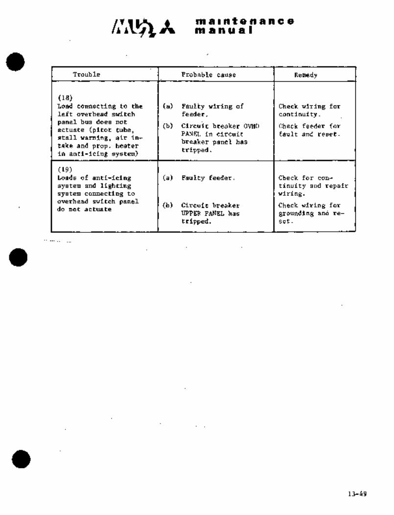
i´•
~´•t´• tio ii in ii a Ino a Ito f a a a a a 8
TLoubl~ Probable cause Remedy
(18)L’oa~d connecting to the (a) PBuit)i wiling of Check wiring for
left overhead switch feeder. continuity.panel’bus does not
(b) Circuit breaker OVHD Check feeder foractuite (pitot tube,
PANEL in circuit fault and reset.stall warning, air in-
breaker panel hastake and prop, heater
tripped.in anti-icing system)
(19)Loads of anti-icing (a) Faulty feeder. Ch~ck for con-
system and lighting tinuity and repairsystem connecting to wiring.overhead switch panel (b) Circuit breaker Check wiring fordo not actuate
UPPER PANEL has grounding and re-
tripped. set.
13-49
in’i a ii ii t e -n a a c etin a in a a
2.9 BATTERY
2.9.i GENERAL DESCRIPTION
The batteries are two nickel cadmium. They dre installed in the aftelectrical compartment, No.l battery on the LH side and the No. 2
battery in the’ center.
Since high discharge current is necessary for engine starting, the
nickel-cadmium battery which has superior rapid discharge character-
istics is used. This battery has such advantage, but, on the other
hand, it is too sensitive for poor maintenance. Insufficient main-
tenance not only causes the battery not to exhibit full performance, butalso damages it, so the following special care should be taken to
obtain the peak performance and life.
Operational practice to prevent battery overheating:
a. Reduce the number of consec~utive engine starts by´•programming the
use of well regulated external power supply when a series of short
duration flights or consecutive engine starts are planned. Also,avoid prolonged engine cranking.
b. When ambient temperature or engine oil temperature is high, avoid
series-batteries engine start and perform parallel-batteriesengine start.
c. When battery is charged after engine-starting by battery, it is
advisable that engine RPM is set to idling condition until charg-ing current drops.
Maintenance practice to prevent battery overheating:
a. Perform visual inspection and maintenance check periodically.
b. Th~ use of a service log about the following items provides an
accurate service record of battery inspections and malfunctions.
It can also be a useful tool in determining the optimum periodbetween reconditionings.
(i) Voltage of each cell before maintenance
(ii) Voltage of each cell after maintenance
(iii) Water quantity supplied to each cell
c. Frequent inflight monitoring of the aircraft bus voltage and load
current will provide an indication pf any abnormal condition.
d. During extended ground operation,.under high outside ambient tempera-
tures, keep the battery loads to a minimum and ensure there is
adequate battery compartment ventilation. Additional ventilation
may be provided by openingthe battery compartment access door or
using forced air ventilation.
1´•3-50

m a a t’co a a a a a~On a a a ~a I
3 1G j
’ii
rjiz\I
PI~1i iiie
i i!I
;i/
i. No. Ibattery2. No.2battery
103. RatterSr vent -iine
4. No.l battery rela)i5. External poarer sou’rce relay
6. No. 2 battery relay7. Emergency relay ~,48.. Room light circuit breaker
9. Battery plug10. Battery temp. sensor plug
Fig,. 13-16 Battery
13-51

CIV42 m a i at a a a ii a a
m anual
2.9.2 REMOVAL AND INSTALLATION
(1) Make sure that the battery switch is in OFF position and remove
battery plug.
(2) Remov~ plug for battery temperature sensor.
(3) Loosen clamps and remove vent tubes.
(4) Cut off safety wire, loosen wing nuts, lay attaching rods on each
side and take out battery.
(5) Install in´•reveuse sequence of removal after cleaning battery stand.
2.9.3 VISUAL INSPECTION
Visually inspect the battery for thefollowing items and conduct a
detailed investigation when any of the abnormal conditions are noted.
Perform reconditioning service on reference to the Paragraph of trouble
shooting.
(1) Cell case distortion.
(2) Burn marks or signs of overheating on battery terminals or cell
links.
(3) Overflow of electrolyte or white deposit on the tops of the cells.
(4) Check electrolyte level and adjust if necessary (See Para. 2.9.4.(4)),
blOT I~
The electrolyte level rises considerablyduring charge, and then drops fairly rapidlyfor anhour or so after charge. Adding water
to a discharged,battery is to take therisk
of Ilquid overflow during charge, causingdamage to cell, so careless adding of water
should be avoided.
Frequent inspection ofelectrolyte level is
desirable and supply of water periodicallyor at bench check is recommended.
(5) Measure electrical leakage between battery connector pin and
battery case.
(6) Any clogging in battery vent hole, check for clear (unclogged)battery vent hole.
13-52

X marnaenancean a a a a I
2.9.4 MAINTENANCE
Recohditib~ing services are determined ~ainly by the airplane flighthours depending on:
(1) Number of engine startings bybattery.
(2) Ambi~nt temperature.
It is recommended to perform it every 100 flight hours and, if~ the
batt~ry is subjected to severe starting and high ambient temperature,at 50 flight hours.
NOTL
(9). Anything aSsociated with the lea~ acid battery(acid fumes included) should never come in
contactwith the nickel-cadmium battery or its
electrolyte. Even traces of sulfuric acid from
a lead acid battery entering the electrolyte of a
nickel-cadmium battery will result in damage.
(ii) The electrolyte used in nickel-cadmium batteries
is a caustic solution of Potassium Hydroxide.Use rubber gltres, rubber~apronand protectivegoggles when handling this solution.
If electrolyte gets on the skin, wash the affected
areas with large quantities of water, neutralize
with 3 percent acetic acid, vinegar or lemon juice.If electrolyte gets into.the eyes, flush with
water and get´•immediate medical attention.
(1) Inspection
Check-battery for Ynstalled condition, then remove it and performvisual inspection per Para. 2.9.3 (1) thru
(2) Cleaning
(a) Remove white deposits on the top of the cell and cell connector
using non-metallic brush.
(b) Make sure that vent caps are properly tightened.
(c) ’Tip batterp´•on side.
(d) Flush with tap water.
(e) Remove excess water using compressed air.
13-53

no a I n ;f ´•BB Iii a n a e
no re a u h I
NOTE
~i) ~O not use metal brush.
(ii) Do not attempt to clean the battery with solvents,acids or any chemical solution.
(iii) Remove battery coler to avoid gas accumulation
while reconditioning.
(iv) Keep rings, metal’w3tch bands and tools away
from the exposed parts of the battery to preventfrom a. short circuit.
(3) Leakage current flow check
(a) Using a tester, such as Simpson 261 or 263 u7hich has an amperage scale
of the minimum of 500 mA, measure the, leakage current flow connectingterminal of tester with terminal of battery, and terminal of
tester with battery case. Also measure the leakage current flow connectingterminal of tester with terminal of battery and terminal of
tester with battery case.
(b) If the readings exceed 50 mA even though cleaning is accomplished per
Para. (2), disassemble the battery, flush and check coating of battery case
and cell case for abnormal conditions.
NOTE
Estimate the quality of battery not by between
battery terminal and case but by electric current.
(4) Charging and electrolyte level adjustment
(a) Charge the battery at room temperature by applying 28.5 constant voltagemethod and continue until the current tapers off and stabilizes at below
10 amperes.
(b) Cut-off the charging and loosen the all filler caps from each cell, then
allow to stand for three hours.
(c) Remove filler caps and check level and adjust, if necessary, to the proper
level above the baffle inside the cells by adding distilled, deionized or
demineralized water.
(d)´• Tighten the filler caps to original condition.
13-54

A m a Int a a a a a a
ao a a a a I
Electrolyte LevelManufacturer I Battery Type
above Baffle
Marathon or Sonotone CA-5 1/ 8 in. (3. 2 mm)
,t CA-BOH ".1/ 8 in. (3. 2 mm)
1, I, CA-B1H 1/8 in. (3. 2 mm)
Gulton GB-4 OA 3/8--1/2 in. (9. 5--13 mm)
n GB-122 1/8v 3/8 in. (3. 2´•v9.5 mm)
2 thru 4 hohrs after charging.
2 thru 24 hours after charging.Liquid level
NOTe
(i)As the liquid level is different due to charging
Fille~ cap~condition, the level should be measured after
charge.
(ii) Do not use any equipment associated with lead
acid battery or its electrolyte in liquid level
adjustment. Electrolyte is solution of potas-
slum hydrdxide and alkaline, and even traces of
sulfuric acid from a lead acid battery enter-Baffle
ing the electrolyte of a nickel-cadmium batterywill result in damage.
(iii) To adjust liquid level, use only distilled water.
The battery is easily contaminated through the
use of tap water which contains minerals,
chlorines, softening agents´• and other foreign Fig. 13-17materials.
(iv) For liquid level adjustment, distilled water is
generally used, but cells which havelost
electrolyte by accidental overfilling may have
a lower specific gravity than i. 24, so they should be sent to the BatteryIl~lnufactureS for adjustment. The battery which has specific gravities rangingbet\~een 1.24 and 1.32 is normal.
(v) After pouring distilled´•water, yechstrgipg is recommended to prevent water
freezing.
(vi) Liquid level measurement
Remove each cell filler cap and look down into the vent well to determine
liqllld level. If it is impossible in this manner, use a glass tube, open on both
plates. I)lace the inde,x Singer over the top open end of the tube and remove
ends. Insert the tube into filler opening deep enough to touch the top of the
the tube from the filler well, The level ~in the lower end of the tube shows the
)i9Mi~ level above the oC the plates. (See Fig. 13-17)
13-55

c~stoo a Int a a a a a a
no a to a a I
(5) Capacity check
(1) AlLcr rrcharenli in ocen~d.nco until Para 14) above, chacli for chsrgin~- acapacity as follows:
Discharge the battery at the discharging rate of one hour or two hours by
connecting the resistance lo~d bank or some equipment suitable to obtain
the constant discharge current by monitoring the voltage until cut-off
voltage is reached and then measure the time required.
Battery Discharge Current (Ampere) Cut-offManufacturer (V)
Type 1H Disch.Rate 2HDisch.Rate Voltage
Marathon or 17 19.0CA-5 34Sonotone
,1 CA-20H 20 11 19. 0
~1 CA-21H 20 11 19.0
Gulton GB-´•I-OA 35 17 19. 0
GB-122 20 11 19.0
NOTE
(IWhen ambient temperature is high, two hour dis-
charging rate which has a little temperature rise,
is recommended.
(b) The time to reach cut-off voltage must be longer than 42
minutes at a one-hour rate discharge and 84 minutes at a
two-hour rate discharge.
NOTL
If discharging time is less than 42 minutes or 84
minutes, respectively, the battery should be deep-cycled and a capacity check made.
In this case, measure individual cell voltages after
42 minutes or 84 minutes, depending on one- or
two-hour rate. If ally cell is below one volt, re-
place it or again perform a deep cycling and capacitycheck.
(li). The charging capacity of a nickel-cadmium battery,different from lead acid battery, can not be measured
byelectrolyte specific gravity.
4-1-7813-56

C~1$5 It a t~ia t a a a a a a
in a ii a a I
~eep-cycling
(a) i=ontinue discharging in Para. C5);
(b) Short out each cell aB it drops below 0.6 vijlts by using copper
shorting clips, one by one, while the load is still applied.
(c) When about 750/0 of total cells hare been shorted, a i. 0 ohm resistor of
1 thru 2 watts should be placed across remaining cells. The batteryshould remain shorted as above for a pgriod of 3 or more hours.
NOTIE
After stopping discharge, cell capacities recover
in process of time. In this condition, if cells
are s~ort-circuited, high short-circuit current
may burn cells. Therefore, short-circuit of cells
should be made during discharging.
(7) Final charge
(a) Charge thebattery by the constant current method as follows.
Manufacturer ttery Type Charge Current (A) I Charge’ Time (H)
Marathon or Sonoton CA-5 8.0 7
1( .CA-20H 5.0 7
1, rr CA-21H 5.0 7
Gulton GB-40A 8.0’ 7
GB-122 5.0 7
NOt E
For perfect dharging of battery, charging capacity,140~0 of the ampere-hour is necessary. Therefore,if the-charging -cuSrent drops´•~auring charge,’adjus;tmanually tij maint~in propdr charging current.
(b) During the final 5 minutes of charge, the voltage of each cell should be
’checked. Each cell shodld be between 1.55’ V thru ’1.75 V.
13-57

m 8 i at la a a a amaaaas
NOTL
(ij Charge shouid not be star_ted if the batterytemperature is above 100 F.
If the temperature Is raised up more than 1200Fwhile charging, stop the charging and continue
after cooling.
(ii) When any cell in which temperature is raised
remarkably (more than 680F above starting
temperature as an aim) or in which the voltage
reaches high value (more than 1.75 V), there
is the possibility of low level of electrolyte or
damaged separator.If it seems that it is caused by poor adjustmentof electrolyte level, add about 5 thru 10 cc
water judging from the conditions at that time
and recheck the level after charging.The cell which does not recover after adding
water should be replaced.
(ili) If anycell fails torise to at least 1.55 volts,the constant current charge should be continued
for an additional hour. Any cell that fails to
rise above 1.55 volts should be replaced.
(iv) When replacing cell, do not use cell other than
the one of the same manufacturer. A~so the cell
of the nearest manufacturing date is desirable,if possible.
(8) Inspection after reconditioning
Check for the following items
(a) Electrolyte level [See Para.(4)1
(b) Leakage current flow [See Para. (3)1
(c) Installation torque of connector nut between cells
Manufacturer Battery Type Nut Installation Torque
Marathon orCA-5 35- 50 in-lbs(40- 58 kg-cm)
Sonotone
,I CA-20H 35-´•50 in-lbs(40-- 58 kg-cm)
(I CA-B1H 35~ 50 in-lbs($O-- 58 kg-cm)
Gulton GB-40A 34 38 in-lbs(399- 44 kg-cm)
GB-122 34~ 38 in-lbs(39 h´•44 kg- cm)
13-58

~I s ~isii h:a’i-1-:uI;a ~m a a Y PP i)g
2.9.5; STORAGE
b~t’t8ry Shbuld be stb~ed’ivith cdmplet8ly aiscBai´•ged coriditiod;
Stora~e can be dbnP in an ainbient betiireen ;5dOC and +700C.jFdrlong period ~jf sto´•i~agej thin cozit 6f grease should be applied on conne;ctors
between cells. A battery beilig placed intb Service after long Period of storageshould be given B freshening charge.
2,9.6 TROUBLE SI´•IOOTING BATTERY
Trouble I Probable Cause Reniedy
Decrease of capacity Unbalanced cells. /Perform deep cycling.
Voltage is not gene- a. Defective connection Find out defective terminal
rated I of connecting bars connector by a voltmeter.
between cells. IClean and retighten using a
specified torque.b. Poor contact of ICheck contact surface of
battery connector. connector for dirt. Clean or
reDlace if neces
White crystals are: a.´• Excessive charging Clean battery and charge.found on the tap~oi‘ cell current or surroundingor electrolyte is found temp, is too high.on bottom of battery b. Electrolyte quantity is C1´•ean battery, charge and
case not proper. check for electrolyte level.
c. Loose vent cap or Cleanbattery and tighten vent
defective O-ring. Icap or replace O-ring.
Cell cases are i a. Overcharging, lieplace defective cells.
distorted I b. Operation under im-
proper electrolyte level.
Failure of one or I a. Different temp.,charg- Charge by constant current
more cells to balance ~ing efficiency and self- charging for more time than
with others discharging of each cell.lspecified. If these cells still
fail. to rise to the required
voltage, replace them.
One ~r more cells rise I a. Insufficient electrolyte. Adjust electrolyte level.
exCes3ively high in I b. Damage of separator. Replace cells.
temperature or voltagethan other cells while
cha rging
Foreign material is a. Foreign substances are Replace´• if capacity is insuffir
deposited I most commonly intro- ~:lcient.d~iced irito the ceil thru
the‘addition of impurewater or water contami-
nated with acid.
13-59

m a i a t a h a Pi (6 Bi/m a to a ~i
Trouble~ P1´•c,bnble
b. Charge by exeessive
high rate charging.c. Charging without
sufficient electrolyte.d. Too high a c~oncen-
tration of electrolyte.
One or more cells Unbalanced cells. Perform deep cycling.
Irequire more water
than the others
Electrolyte consump- Charging voltage is too Set charging voltage properly.tion is relatively high high or an ambient
temperature is too high.
Corrosion of top Presence of acid fumes. Clean battery and batteryhardware I I compartment.
Cell connectors I Connector has not been Tighten with proper torque.
become hot in charging properly tightened.
or discharging or
connector shows burn
marks
Voltage is detected Electrolyte spews from if leakage current exceeds
between connector cell and wets the 50 mA, flush the battery with
pin and battery case outside of cell. tap water per Para.9.4.(2).
Electrolyte’is if the current still exceeds
conductive,‘so vol- 50 mA after cleaning and
tage can be read, drying, repeat disassembly,
cleaning and inspection.
13-60

r~ ~ti ~i
maintenancem a a a a I
3. ICPOWERSUPPLYSYSTM
3.1 GENERAL DESCRIPTION
Constant frequency AC power is generated by a 250VA static inverter
installed on the RH side of main junction box. The inverter can be
operated by DC generator at normal operation or external power or batteryon the ground check when the inverter switch on the LH switch panel is
turned to MAIN from INV. AC input power is supplied generally to the
inverter through the circuit breakers in cockpit, but while startingengine, the power is supplied through DC-DC converter (constant voltageequipment) operated automarically in engine start only and installed on
RH main junction box in order to prevent AC power voltage drop, togetherwith DC power voltage drop, and regular AC power is originated.
The AC power system supplies 115V, 400 Hz AC power to the fuel quantityindicating system, ITT indicating system (Aircraft S/N 6525A) and trim
indicator lighting system. It also supplies 26V, 400 Hz of AC power to
the oil pressure and fuel pressure indicating systems. The inverter fail
detecting relay is connected to the 115 VAC output circuit and if this
output falls below a specific value, the contact closes and illuminates
the "INVERTER FAIL" light on the annunciator panel...
Should failure of the main inverter occur, a standby inverter is
installed for a backup (located adjacent to the main inverter in
the RH main junction box). The standby inverter is switched ON
by placing the inverter switch, LH switch panel, from the MAIN
position to the STBY position, while the STBY INV circuit breaker
is in the closed position.
3.2 INVERTER
The inverter cbi~verts 28V DC power of the aircraft to 115V and 26V, 400
Hz AC power. This inverter is transistor type and the output voltage is
constantly regulated by the level adjusting circuit regardless of variation
of load and circumferential temperature. The AC power of stabilized
frequency Is supplied by the L/C tuned oscillator.
The rating capacity is 250VA, but 150~ (375VA) of overload current can be
supplied for at least five minutes. In case of load more than 160~5 or
grounding of the output terminal, the overload detecting circuit works, to
shut down the inverter output, thus protecting the inverter.
3.2.1 REMOVAL AND INSTALLATION (See Pig. 13-10)
(1) Remove the RH access panel of main junction box.
(2) Disconnect an electrical connector of inverter.
(3) Remove four attaching bolts and remove inverter.
(4) Install In reverse sequence of removal.
3-31-90 13-61
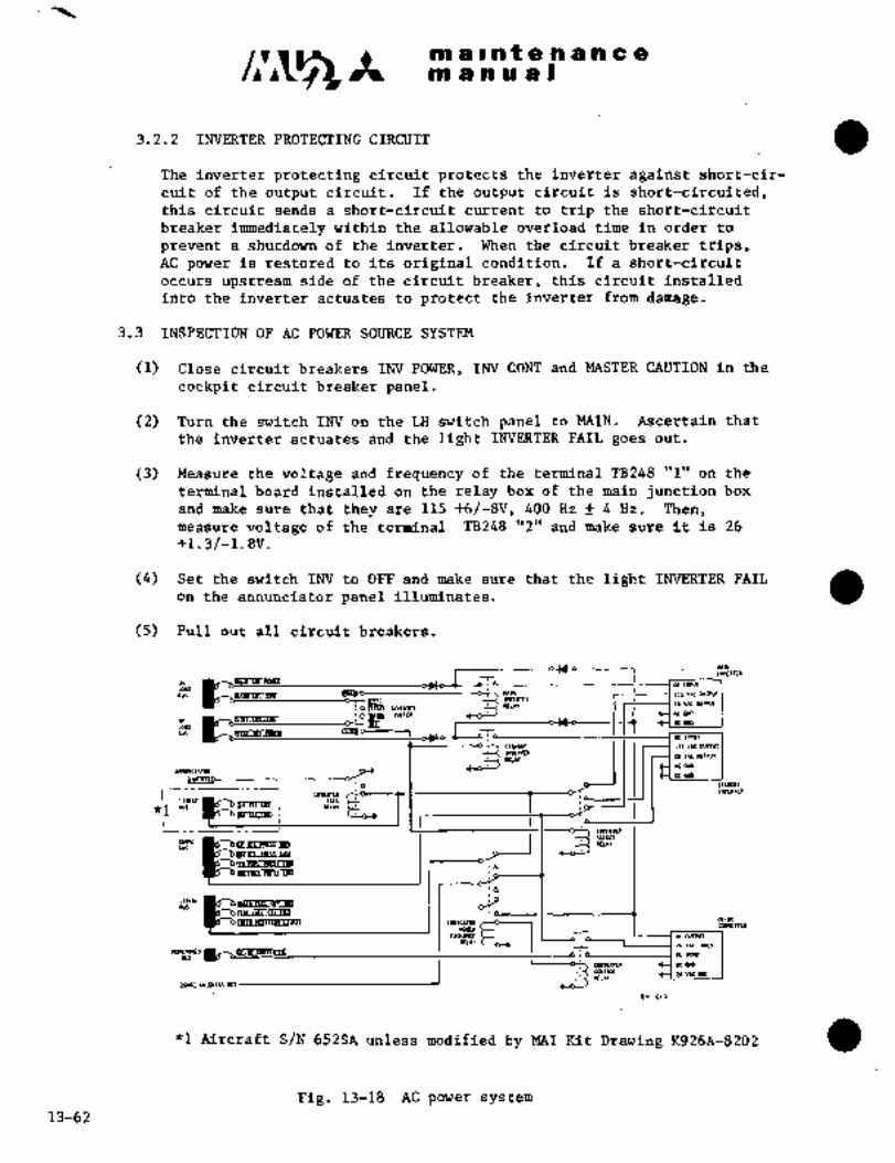
"´•a
ma~ntenancem a a a a i
3.2.2 INVERTER PROTECTING CIRCUIT
The inverter protecting circuit protects the inverter against short-cir-
cuit of the output circuit. If the output circuit is short-circuited,this circuit sends a short-circuit current to trip the short-circuit
breaker immediately within the allowable overload time in order to
prevent a shutdown of the inverter. When the circuit breaker trips,AC power is restored to its original condition. If a short-circuit
occurs upstream side of the circuit breaker, this circuit installed
into the inverter actuates to protect the inverter from damage.
3.3 INSPECTION OF AC POWER SOURCE SYSTEM
(1) Close circuit breakers INV POWER, INV CONT and MASTER CAUTION in the
cockpit circuit breaker panel.
(2) Turn the switch INV on the LH switch panel to MAIN. Ascertain that
the inverter actuates and the light INVERTER FAIL goes out.
(3) Measure the voltage and frequency of the terminal TB248 "1" on the
terminal board installed on the relay box of the main junction box
and make sure that they are 115 ~fj/-8V, 400 Hz f 4 Hz. Then,measure voltage of the terminal -TB248 "2" and make sure it is 26
+1.3/-1.8V.
(4) Set the switch INV to OFF and make sure that the light INVERTER FAIL
on the annunciator panel illuminates.
(5) Pull out all circuit breakers.
b~rrm-
:op~0 nlla CO-’-u- i
n7-~
115 vs cwrPurlararra
re v~c.mrsur
aslm
:~LLIn, NLI OT1 11101
*a~aro _1 9
Iloluma
~.VII.I.M
I
"1 Aircraft S/N 652SA unless modified by MAI Kit Drawing ~92619-8202
Fig. 13-18 AC power system
13-62
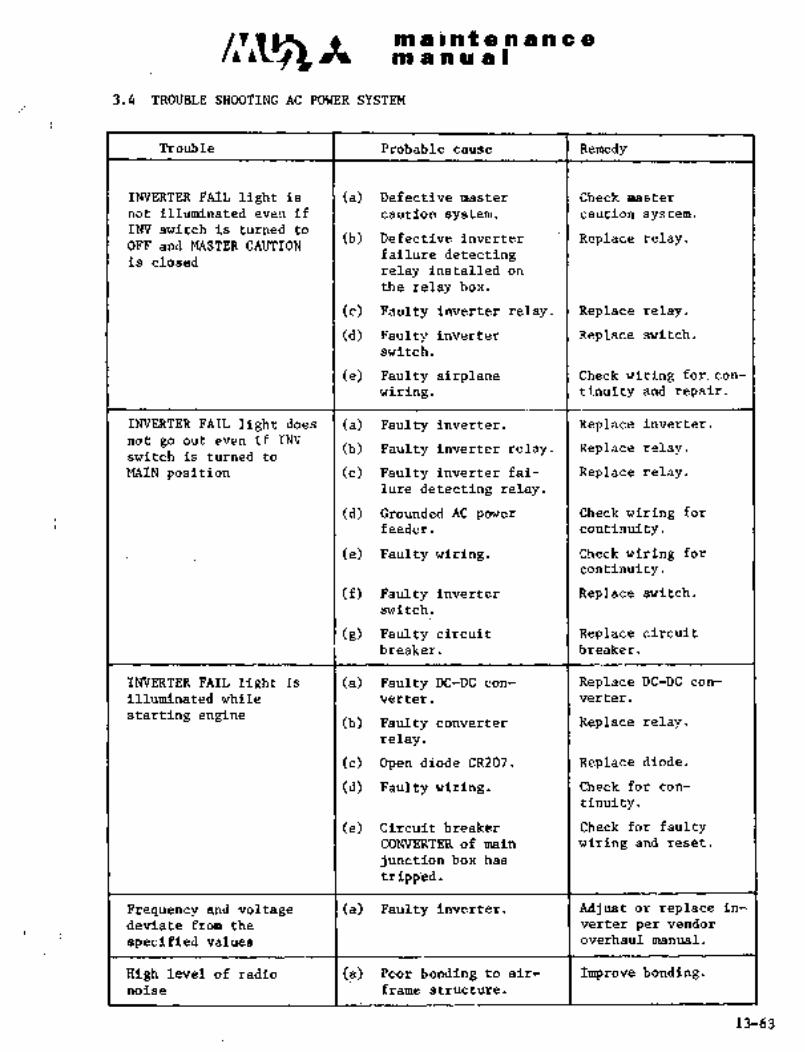
.iii a bfif a PI a a a a
m a iaO
3.4 TROUBLE SHOOTING AC POWER SYSTEM
Trouble I Prbbable cau‘se 1 Remedy
INVERTER FAIL light is I (a) Defective r;iast’er I Check master
not illuminated even if I caution system. caution system.INV switch is turned to
(b) Defective inverter Replace relay.OFF and MASTER-CAUTION
failure detectingis closed
relay installed on
the’relay box.
(c) Faulty in\ierter relay. Replace relay.
(d) Faulty inverter Replace switch.
switch.
(‘e) Faulty airplane i. Checkwiring for, con-
wiring. I~tinuity’and repair.
INVERTER FAIL light does I (a) Faulty inverter. I Replace inverter.
not go out even if INV(b) Faulty inverter relay. Replace relay.
switchis turned to
MAIN- position (c) Faulty inverter fai- Replace relay.lure detecting relay,
(d) Grounded AC power I Check wiring for
feeder. ´•I´• continuity.
(e) Fgultywiring. ~I Check wiring for
continuity.
(f) Faulty inverter Replace switch.
switch.
(g) .Faulty:circuit Replace circuit
breaker. ´•~ji-eaker.
~NVERTER;FAIL.lighf Is::~ (a) Faulty DC-DC con- Replace DC-DC con-
illuminated. while verter. I´•verter.
starting engine (b) Faulty converter ´•(:Replace relay.relay.
(c) Open diodd CR207. Replace diode.
(d) Faul:ty wiring. :I Check for con-
tinuity.
(e) ´•C´•ircuit breaker Check for faultyCONVERTER.o.f main wiring and reset.
junc t ion tioi´• ´•bas
tripped
Frequency andvdlt~ ::-l_.(a) ,Faulty-inverfer, l:AdJus+or replace~n-deviate -verter per´• vendor
specified values ´•II :I overhaul manual.
High level of rade6 1::.~ ´•:l-l~a):::´•´•Po.or: :bondlngl´•’td airr Improve bonding.noise
13-63

~a a a t a or a a e a
~n a a a a B ORIGINAL
As Received ByAT P
4. LIGHTING
4.1 LANDING AND TAXI LIGHT
Landing and taxi lights are installed on both sides symmetrically on the
lower sides of the nose. These are used as landing lights at landing and
as taxi lights while taxiing.
These lights are controlled by a switch LDG TAXI located in the overhead
switch console and they are extended or retracted separately as the
switch is placed in MT or RET.
If the switch is placed to OFF, the light will turn off at the intermediate
position.
The landing light circuit is protected by circuit breakers, LDG TAXI LAMP
and LDG d TAXI LIGHT CONT on the circuit breaker panel. Lamps, 26V 250W
sealed beam type, are so installed that the center of the light beam is
directed to the forward of the attaching position.
4.1.1 REMOVAL AM) INSTALLATION (See Fig. 13-19)
(1) Remove rear inspection panel of landing Iand ta~d lights. I
(2) Disconnect wiring from lights.
(3) Remove outer frame from landing and
taxi lights by removing 6 screws.
(4) Remove landing and taxi lights byremoving 11 screws.
(5) Install in reverse sequence of
removal.
4.1.2 ADJUSTMENT OF LANDING LIGHTS
Fig. 13-19 Landing and taxi light
(1) Level the airplane.
(2) Place target boardat 18 ft. 8 in. (5.7 m) forward of the nose
landing gear wheel-axle, perpendicular to axis of airplane. Using
plumbs suspended from four alignment points at STA 1435 and 8880,
project the distance between two points on each side of fuselageon target board to locate axis of aircraft.
(3) Using 32.7 in. (830 mm) long plumbs suspended from four alignmentpoints at FUS STA 1435 and 8880, project the distance between two
points on each side of fuselage on target board.
(4) Place RH landing light in MT position. Adjust position of lightso that center of beam may fall on a circle of 3.16 in. (80 mm)radius drawn on target board with center located 27.55 in. (700 mm)to the right of axis of aircraft and projection that is obtained
in accordance with paragraph (3) above.
13-64

maintenanceIV1 anual
(5) Adjust LH landing light to the symmetrical position with RH lightin the same way.
(6) Return landing lights to RET position.
4.1.3 OPERATIONAL CHECK
(1) Close circuit breakers LH LDG 6 TAXI LAMP, RH LDG 6 TAXI LAMP,LH LDG 6 TAXI LIGHT CONT and RH LDG 6 TAXI LIGHT CONT.
(2) Place landing and taid switch to EXT position, and landing and taxi
lights are actuated and illuminate in extended position.
(3) Place switch to RET position, and landing and taxi lights are
actuated and go out and retract.
NOTE
Check for noise and interference
during operation of landing lights.
4.1.4 MAINTENANCE PRACTICE
Refer to Grimes Manufacturing Co. "OVERHAUL INSTRUCTIONS WITH ILLUSTRATED
PARTS LIST" Manual Number H5-50069.
4.2 TIP TANK TAXI LIGHT (If equipped)
A taxi light is installed in the leading end of each tip tank and is
controlled by the TAXI switch in the overhead switch console. The lightsilluminate when the TAXI switch is placed to the ON position and go off
when the switch is placed to the OFF position.
4.2.1 REMOVAL AND INSTALLATION (See Fig. 13-20)
(1) Make sure all aircraft power is O~F.
(2) Remove 6 screws attaching the shroud.
(3) Remove shroud and shield.
(4) Remove 3 screws from the retaining clips; remove the clips.
(5) Bring lamp forward from socket and disconnect electrical wiring;identify the wires.
(6) Install in reverse sequence of removal.
13-65

maintenancemanual
NOTE
(i) Apply RTV732 adhesive sealant (Dow Coming Co.) or equivalentto inside shroud rim before installing as required.
(ii) When installing, make sure that the shield is on the inboard side
of the shroud.
4.2.2 OPERATIONAL CHECK
(1) Close circuit breaker "NO.2 OVHD PANEL (LIGHT)".
(2) Turn taxi light switch to "TAXI" position. Make sure that taxi lights illuminate.
(3) Turn switch to "OFF"’ position, and taxi lights go out.
(4) Pull outcircuitbreaker.
1. Tip tank
2. Spacer3. Ring assembly4. Screw
5. Lamp6. Clip
76
7. Screw 10
8. Shell g’a9. Shroud
10. Screw
5\4 ‘3
Pig. 13-20 Tip tank taxi light (LH shown, RH opposite)
4.3 NAVIGATION LIGHT
Wing tip lights and tail light are installed on the outboard sides of the LH and RH tip tanks
and rearmost section of the fuselage, respectively, and they can be controlled by switch NAV
located in the overhead console. When they are on, their color is red (LH tip light), green (RH
tip right), and white (tail light), and they are stationary.
4.3.1 OPERATIONAL CHECK
(1) Close circuit breaker RH UPPER PANEL.
(2) Place NAV switch ON. Verify that wing tip lights and tail light illuminate.
(3) Place switch OFF, verify that lights go out, and return circuit breaker to open position.
4.4 ANTI-COLLISION LIGHT
Anti-collision lights required by regulation are installed one each on the upper surface of the
vertical stabilizer and the lower fuselage (if installed). They are controlled by switch BEACON
in the overhead console and radiate a red flashing light to all directions.
13-66 1-10-98
li;ti ~a I iii t a ii a ii cc am pi uial
4.6.1 CHECK
(1) breaker,Ijp~ER P~JE‘L (Aircraft 66i~A).
’(2) an’tiL-coliision light switch BE~CON lo ONi Verify that
ariti-collision lights on top of vertical stabilizer and on bottom
surface of fuselage rotate and illuminate.
(3) Place switch OFF, verify that anti-collision lights cease to rotate
and go out, and return circuit breaker to open position.
4.5 STROBE LIGHT
The strobe lights are installed on the outsides of LH and RH tip tanks
and tail cone, and are operated by STROBE~ switch in the overhead console.
The strobe light flashes out at 50 cycles per minute.
NOTE
(i) When cover-attaching screws are unscrewed
to remove’tip tank strobe light, navigationlig~t cover (colored glass)-also comes off,so take care of handling.
(ii) When strobe light is installed or the tiptank is replaced, pay attention not to cause
fuel leak~due to rough work on thesmall
conduit tube in the tank.
(iii) When strobe lightinstalled´•on tip tank is
replaced, perform leak test and make sure of
no leaks at conduit tube. See Chapter VII
for leak test.prqcedure.
4.5.1 OPERATIONAL CHECK’
(1) Close circuit breaker RH UPPERPANn.
(2) Place strobe light switch STROBE to ON- and:.ascertain that the
strobe lights on LH and RH wing tips and tail cone flash out.
(3) Place the~ si~itch OFF and,upon seeing, t~je lights stop ´•flashing,pull out Circuit breaker.
.r
13-67

IPI 1 I’ n9enance~nn a a a a I
4.6 ICE INSPECTION LIGHT
The ice inspection light is installed in the LH outboard engine nacelle
and illuminates the outer wing half. This light is illuminated by the switch
WING ICE LIGHT on the overhead console.
4.6.1 OPERATIONAL CHECK
(1) Close circuit breaker RH UPPER PANEL.
(2) Set the ice inspection light switch ICE LIT to ON. Ascertain
that the ice inspection light comes on, illuminating the LH out-
board wing leading edge.
(3) Place the switch OFF, make sure that the light goes off, and then
pull out the circuit breaker.
4.7 INSTRUMENT LIGHT
Each instrument is illuminated by post type lights located’above the
instrument. The lighting system consists of three groups: pilot flightinstrument group, co-pilot flight instrument group and engine instrument
group. The brightness of each group can be adjusted indepen~ently. The
instrument light circuit is protected by circuit breaker INST PANEL LIGHT.
The brightness is adjusted by rheostats PILOT FLT INST,~ COPILOT FLT INST
and ENG TNST in the overhead console.
PILOT FLT INST: Standby compass, airspeed indicator, altimeter, turn
and bank indicatori rate of climb indicator, outside
air temperature indicator, attitude gyro, magneticcompass natigation instruments and volt-ammeter.
GO-PILOT FLT INST: Cabin rate of climb indicator, cabin altitude differen-
tial pressure indicator, cabin pressure regulator,co-pilot flight instruments, fuel quantity indicator,fuel totalizer and vacuum gauge.
ENG INST: Torquemeter, ITT indicator, fuel flow indicator,tachometer, oil pressure indicator, oil temperatureindicator, trim aileron positionindicator and fuel
pressure. indicator.
13-68
Ma rntBan a a u’a I
4.7.1 OPERATIONAL CHECK
(1) Close circ~iit breaker I~JST PANEL LIGHT.
(2) Turn ~tieostats in the overhead console (for pilbt f~ight itlstru-
ments, co-pilot flight instfumelits and eng~irieinstruments) clock-
wise, and the f62lowing instrument lights gain brightness.(a) Pilot flight instrument light (Pillar light)(b) Go-pilot flight insfrument light (Pillar light)(c) Engine instr~iment light (Pillar light)
(3) Turn rheostat counterciockwise to original position. Pull circuit
breaker to open.
4.8 PANEL LIGHT
The LH and RH switch panels and overhead console are lighted~internallyby means of an Pdge-lighted panel and brightness is controlled by the
rheostat PANEL in the overhead ronsole. The panel illumination circuit
is protected by circuit breaker INST PANELLIGHT. The forward circuit
breaker panel is illuminated by a post type ligt;t installed on the paneland center circuit breaker panel is.illuminated by a light~ under the arm
rest. The light is illuminated by a switch installed under the arm rest.
This circuit is protected by circuit breaker MAP LIGHT.
4.9 RADIO CONTROLLER PANEL LIGHT
A panel ´•type illumination system is built into each radio controller and
brightness is adjusted simultaneously by rheostat in the overhead console.
Thecircuit breaker for this system is thesame as the instrument lightcircuit.
4.10 TRIM INDICATOR LIGHT
The rudderand elevatortrim indicator~on th~ center pedestal are illuminated
by electro luminesceht in´•the dials. This :sysfem:is operated by115V 400 Hz AC power and:the lights come on when the switch’ IND LITS on
the center instrument panel is turned to DTM. Brightness of the lights is
previously adjusted. If nec’essary, readjusting is possible by means of
the variable resistor installed behind center pedestal. This circuit is
protected by´•circuit breaker -TRIK POS LIGHT.
4.10.1 OPERATIONAL.CHECK
(1) Closi~ circuit breakeys.INV POWER,INVCONT, INS;r PANEL LIGHT and
TRIM POS LIGHT.
(2) Place switch INV on the LH to MAIN.
(3) Turn switch IND LIiTS inthe overhead-console to DIM. Make sure
that elevator and rudder trim dials grow light:
(4) Place the switch OFF and pull out the circuit breaker.
13-69

in a ii a a Iin a i nt e’n a a C a
4.11 CENTER PEDESTAL iIGHT
The center pedestal light is installed on the rear sPde of overhead
console. When map light and pedestal light switch is in MAP position,it illuminates map, and in NORMAL position illuminates center pedestal.The center pedestal light is supplied power through circuit breaker INST
PANEL LIGHT and brightness can be adjusted by the rheostat ENG INST in
the overhead console.
4.12 MAP LIGHT
The map lights are installed one each on the lower section of the LH and
RH control wheel and one combination light of center´•pedestal light in
the cockpit ceiling. The nap lights in the control wheels are controlled
by rheostats in the center of the control wheel. The combination lightfor map and center pedestal light is illuminated when the switch is placedto MAP position, and brightness is controlled by a rheos´•tat installed ad-
jacent to the switch. These map lights are powered through the circuit
breaker MAP LIGHT.
4.13 ROOM LIGHT
The two room lights are installed in cockpit ceiling and continuous cabin
ceiling lighting. The cockpit room lights are supplied power through cir-
LH side of cockpit. The cabin room lights are supplied power through eir-
cult breaker MAP LIGHT and lighted by the switch COCKPIT ROOM LIT on the
cult breaker ROOM LIGHT directly connected to No. 1 battery in the electric
compartment, so ´•they can be illuminated by cabin room light switches,
having no connection with switch operation in power source.
4.14 READING LIGHT
The reading lights are installed in the cabin ceiling above each seat lo-
cation and supplied power through circuit breaker READING LIGHT in the LH
main junction box.
4.15 PRIVATE ROOM LIGHT
The private room light is an extension of the cabin ceiling lighting. The
light is suppl’ied power through circuit breaker ROOM LIGHT connected to
No. 1 battery in the electric compartment, so it can be illuminated by private
room light switch in the private room, having no connection with switch
operation in power source.
´•C
m a ~at e.n a a a a
m a a a a I
a 6.6
Aircraft S/N 652SA.
The cabin sign light is inst~lled on the cabin ceiling and can be
operated by the switch CABIN SIGN on the center instrument panel.When the switch is set to FASTEN BELT, the light FASTEN SEAT BELT
comes on and for CAi)IN S~6N, the light NO SMOKING FASTEN SEAT BELT
comes on. This circuit is protected by the circuit breaker PASS SIGN
LIGHT in the circuit ~reaker panel‘ of the main junction box. Five
lamps are installed in the light assembly and are replaced by remov-
ing the light body from the:front side.
Aircraft S/N661SA, 697SAand subsequent
The cabin sign light is installed.in the ~orward’ceiling of the cabin.
The FSB CABIN SIGN switch (in.the overhead Console), when placed to
the ON position, illuminates the FASTEN SEAT BELT sign while the
NS CABIN SIGN switch tin the overhead console), when placed to ON,illuminates the NO SMOKING sign. These circuits are protected by the
RH UPPER PNL (LIGHTS) circuit breaker.
4.17 CIRCUITBREAKER PANEL LIGHT
The forward circuit breaker panel (side wall) on the LH side of cockpitis lighted by pillar lights and the rear circuit breaker panel is
lighted by light box installedunder the armrest of pilot seat. Each
circuit breaker panel light is controlled by the ON-OFF operation of
button type switch in light box under the arm rest of pilot seat. The
circuit breaker panel light circuits are protected by circuit breaker
MAP LIGHT on circuit breaker panel, together with map light circuit:.
4.18 CIGARETTE LIGHTER.
The cigarette´•lightei-s are installed in the cabin arm rest. This cir-cult is protected by the circuit breaker CIGAR LIGHTER in the main
junction box. Power is supplied´•to each´•cigarette lighter through the
resistor on the RH upper side of the main junction box.
13-71

C~5~il a I ri t 8 a a a c a
ni a a a a)
4.19 LAMPS AND FUSES
Lamp Number I,ol:atjons
#32 7 Master caution light.. p~nel Ijffht, inEtriunent
lights, standbJ cum~,ass light~, ~ir´•e esr,inguisher h:lndle
light, warning’ I.ight ;Ind indiclat;cir lighl, cabin si8~ light
#334 i Engine instrunlent.lighl
#7512 i Wing tip light (Navigat´•ion !i~IlC)
#1683 Tail light (Navigation light!
*1 A- 7079B-24 Anti-collision light,ice inspection light:
#1495 1 Maplight, readinglight
#30$ Private room light.
*2 916-2020/961- Cabin -lightTaOO
*3 4553 Landing light
*1: Grimes Mig. Co., Urbana, Ohio, U.S.A.
"2: Ichiko Industries Co., T,td. fB n n nvn M u u
*3: General Electric Co.
RECEIVE6B BY
~are I-’arts
(lamps, fuses,etc.)
Lamp MS25 237-3 27 2
ASA H334 i 3
MS~5232-’1683 1
MS25232-307 i
ASA #7512 1
~41S25069-:1495
*1 961-2020/961-Ta00 1 g*2 A-707DB-~4
Fuse *3 AGC-S j"´•:1:1,~F;:2*3 AGC-5 i 2
Safety Pin 1 035A-38864 I
NOTE *1 IkkoInd. Co. *4 :Aircraft S/N 652SA,
661SA, 697SA thru
*2 Crimes M-fg Co. 699SA
*3 Co. *5 Aircraft S/N 700SA
and subsequent
13-72

It Pfil a I H~ 8 os a a e a
ra a a a a s
5. WARNING SYSTEM
5.1 STALL WARNING SYSTEM
This system consists of alift transducer, a signal sunrming unit, a control
shaker installed on the cross bar of the column assembly and a flap posi-tion potentiometer. T~e lift transducer actuates the control shaker to
alert the pilot(s) thatthe’~airspeed has decreased to 4 to g kts. above
the stall speed of each flap position.
5.1.1 LIFT TRANSDUCER (See Fig. 13-21)
The lift transducer is installed on the RH
wing leadin~ edgPJ W.STA 4220. Displacementof movable piece exposed on the bottom sur-
face of the wing changes the magnetic flux,changing voltage. An anti-icing system is
provided on the exposed section.
5.1.1.1 REMOVAL AND INSTALLATION
(1) Remove 4attaching screws.
(2) Disconnect wiring connector
I
through access door.
(3) Pull out the assembly showly Fig.13-21 Lift tradsducer
in outward direction of wing.
(4) Install in reverse sequence of removal.ORIGINAL
As Received ByCBUTIOM
AT P
Do not deform exposed movable piece. If
it is bent, do not try to correct it.
5.1.2 FLAP POSITION TRANSMITTER (See Pig. 13-22)
This is a potentiometer installed on the ..~icenter wing trailing edge on RH side, re-
sistance of which varies as flap travels.
5.1.3 SIGNAL SUMMING UNIT lip
This unit is installed os the relay box of
the main junction box and, upon receiving I.´•i
and the lift tra~sducer, sen4s out a signal.,r,to fhP ih~ri´•
Ilr ´•:~i:tti
Fig. 13-22 Flap position transmitter
13-73
no alntenanceno a n u at
5.1.4 OPERATION AND ADJUSTMENT OF
STALL WARNING SYSTEM
5.1.4.1 CHECKOUT BEFORE
ADJUSTMENT
(1) Check vanes of lift transducer for deformation and damage.
(2) Replace flap from UP to 200 position.
(3) Verify that resistance between output terminals B and C of
flap potentiometer is 180n -t´• 10 R
For adjustment, change.position of lever relative to shaft by
loosening set screw on shaft of flap potentiometer.
(4) With flap in UP and 400 positions, verify that resistance
between output terminals B and C of potentiometer is as
follows:
UP position 3000n f 100R (Reference value)
400 position OR
5.1.4.2 OPERATIONAL CHECK
(1) Turn battery key switch ON, make sure that the landing gear Csafety switch is operative, and place flap in 400 position.
(2) Close circuit breakers STALL WARN and L/G CONT.
(3) Place switch STALL WARN TEST on RH switch panel in cockpit in
GND position, and shaker operates and control wheel shakes.
(4) Jack aircraft. (Landing gear safety switch inoperative)
(5) Hold lift transducer vane full aft.
(6) Place STALL WARN TEST switch in nT position, and shaker
operates, and control wheel shakes. Release lift transducer
vane to neutral position; shaker may continue to operate.
13-74 4-1-78

It WP a i a t a a a a a a ORIGINALmanual As Received By
AT P
5...4.3 MEASUREMENT OF SHAKER OPERATING ELECTRIC CURRENT (See Fig. 13-23)
Measure the electric current with the aircraft jacked, landing gear
safety switch inoperative, and flap in 400 position.
(1) Remove LH access panel in the main Ire~
junction box.
(2) Connect 100plA ammeter to lead
wires from E and F terminals of signalsumming unit. (A lead wire from E ter-
minal should be connected to termi-
nal and lead wire from F teninal to
terminal of ammeter.)I
(3) Move vanes of lift transducer forward
slowly by hand. Repeat the process a
few times. The indicator of ammeter
travels smoothly from positive to-ri
negative Record average value
of amperage when shaker operates.
Fig. 13-23 Connect ammeter to
terminal board TB2455.1.4.4 ADJUSTMENT OF STALL WARNING SYSTEM
(1) Attach force applicator CSafe Flight Instr. Corp. P/N 990) to the lift
transducer in accordance with.the following procedure, see Fig 13-24.
(a) Attach gauge to force applicator mount.
(b) Place the hook of applicator on stop pin of vane. Fasten
applicator with fastening knob.
(c) By means of adjusting screw, adjust engagement of tipof pressure arm of gauge with vanes to 0.02 to 0.03 in.
(0.5 to 0.8 mm).
Lift transducer
Stop pin
Backward ~Yhook \NIovable piece
(vane)
Pressure arm Knob
Adjustingscrew Force
applicatorgage
Adjusting knob
Fig. 13-24 Attach force applicatorto lift transducer
4-1-78 13-~5
C~S3 maintenancem a a a a O
(2) Place flap in 400 position.
(3) Apply force of 0.6 G of gauge indication to vanes of lift trans-
ducer by rotating adjusting screw of force applicator. By ro-
tating NULL adjusting screw of signal summing unit, adjustshaker actuating amperage to read within 5yA that is noted
in accordance with 5.1.4.3 (3) of this Paragraph.
(4) Place flap in 200 position.
(5) Apply force of 2 G of gauge indication to vanes of lift trans-
ducer by rotating adjusting screw of force application. By ro-
tating FLAP adjusting screw of signal summing unit, adjustshaker actuating amperage to read within f 5p A that is noted
in accordance with 5.1.4.3 (3) of this Paragraph.
(6) Place flap in UP position.
(7) Apply force of 4.5 G of gauge indication to vanes of lift trans-
ducer by rotating adjusting screw of force applicator. If am-
s perage does not read within shaker actuating amperage of f 5~ A
that is noted in accordance with 5.1.4.3 (3) of this section,
adjust amperage to read within specified value by rotating F
adjusting screw of signal sunrming unit.
(8) Detach applicator and ammeter. Turn circuit breaker off. Re-
store aircraft to original condition.
NOTL
If the shaker actuating amperage is adjusted with the flapin UP position, the amperage adjusted with the flap in
200 position becomes out of order. For readjustment, steps
(4) to (7) must be repeated with flap in 200 position.
CAUTION
Do not adjust sensitivity adjustmentscretr of signal sunrming unit.
5.2 ENGINE FIRE DETECTION SYSTEM
The fire detection system is installed independently on LH and RH enginesand consists of thermistor type continuous temperature sensor, control
unit and warning light.
The circuit for the fire detection system is protected by circuit
breaker LH(RH) FIRE DET.
The system continues to operate even if the MASTER switch is placed to the
EMER position, because the system is operated by battery through the
emergency relay.
13-7 4-1-78

tn a r nt e n a n e
~n a ii iu al
5.2.1 TEMPERATURE SENSOR
Two teimperature sensors with different lengths are installed in Zone I
and Zone II of the engines.
CA U-TION
(i) Temperature sensors should not be, bent frequently.
(ii) Bending radius should be greater than 1.19 in. (30 mm).
5;2.2 CONTROL UNIT
When resistance of~temperature sensor has decreased below 350R due to
fire, the relay in the contro~´•unit isactuated to light warning lamp.The control unit is installed on the LH and.RH sides in the relay panelin the center wing leading edge.
A short discriminator is provided´• in each contrbl unit to prevent the
fire warning circuit from operating when sensor is shorted due- to
failure. Therefore, If the temperature sensor is shorted; the fire
warping light will not illuminate even if the test switch for the
fire:detector is pushed.
5.2.3 WARNING LIGHT
The warning lights are built.in the fire~ extinguisher Bandies, which
are In the instrument~shroud, one for the left and onefor~therightengine.
CAUTION:
Do not pull handle until fire is confirmed.
5.2.4 INSPECTION
When the test switch is and RH fire´• handles
are illuminated in red, indicating that~ the entire circuit of the fire
detector is operating normally. If they donot:illuminate, perform
an inspection in the followlngmanner.
(1) Faulty lampTest lamps built in the fire extinguisher -handle~.
~(2) Faulty control unit’
Check operation. If operation is faulty, replace
13-77

IC m a i nt a n a a a a
m a in a a I
(3) Open wire in circuit or faulty conract
Check continuity of circuit in accordance with wiring diagram.
(4) Short circuit of temperature sensor
(a) Disconnect the connector of each sensor and flexible cable.
(b) Measure the resistance at the plug between inner conductor
and outer sleeve. Resistance more than 200 R is normal.
Shorted wire should be replaced.
CAUTION
In measuring the resistance, use a circuit tester only.When a voltage in excess of 10V is applied, disconnect
connector so that voltage is not applied to the control
uni t.
(5) Open circuit of wire of temperature sensor
(a) Open the nacelle door.
(b) Disconnect the plug at joint sectidn of temperature sensor and
flexible cable.
(c) Check continuity of ilmer conductor of temperature sensor. If
wire is open circuited in temperature sensor, replace.
5.3 OUTER TANK FUEL LOW PRESSURE WARNING SYSTEM
When outer tank fuel is empty or outer tank fuel transfer pump is defective,a warning light LH(RH) OUTER TANK EMP in the center instrument’ panel is
illuminated (See Chapter VII). Test of warning light is performed byclosing circuit breaker LH(RH) OUTER FUEL EMP WARN and turning panelindicator test switch´•to TEST. When indicator light dimmer switch is
turned to IND LITS DIM, warning light can be dimmed’.
5.4 LANDING GEAR WARNING SYSTEM
The warning is given by a horn installed on the forward section of LH
cockpit, and an UNSAFE light mounted on the LH switch panel.
5.4.1 HORN WARNING
The horn sounds if the landing gear control switch is placed to UP
position by mistake when the aircraft is on the ground, or if the nose
landing gear uplimit mechanism is misoperated during inspection, and/orif- the power lever is moved close to FLT IDLE during flight with the
landing gear retracted. The horn ceases to operate with the shift of
the power lever from FLIGHT IDLE to TAKEOFF, or the landing gear control
switch is placed from UP to DOWN.
If the horn sounds in flight, operate the-horn cutout switch adjacent to
the landing gear control´• switch and indicator lights, and the horn will
cease to sound. When the power lever is moved to TAKEOFF position, the
horn cutout switch returns automatically to’the originalppsition.
13-78
CIViS ´•t in~ ~a.C. a titi a a in a
~ii ii a a aJ
5.4.2 UNSAF~ iIGH~
Theunsafe lightis apush-tb-test t~pe w8rnihg light mount’ed on the LH
switch pan~l ali~ can be ´•tested:bg the’ lamp; The light can be
dimmed by tu~ning ~ND LITS on theoverhead switch console
to DIM.
When the following troubles or misop’eta~ions occur in the landing gear
system, UNSAFE light illuminates for warning.
Landing gear control switch is placed’UP on the ground.
(2) Main gear forward door is not closed.
(3) One of landing gear is not perfectly retracted.
(4) One of landing gear is not downlocked.
NOTIE
The UNSAFE light illuminating during re-
tractionandextension’~of the landinggear
is´•normal. The’ UNSAFE light illuminating
after the landing gear extending or retract-
Ing operation has been completed, and landing
gear has been downlocked or retracted perfectlyis not normal.
5.5~ MASTER CAUTION SYSTEM AND ANNUNCIATOR PANEL
The master caution system consists of master caution’ light which indicates
trouble of a system grouped in the annunciatorpanel. The annunciator
panel indicates trouble of a system. It is protected by circuit breaker
MASTER CAUTION.
5.5.1 MASTER CAZITION.LIGHT
The master caution light is a push-´•to-test type light installed in the
center upper shroud and isillur~nated and indicates CAUTION if any
one of the systems- shown on the annunciator panel is abnormal.
After confirming~the nature of failure from the annunciator panel,
push the.master caution light’,. then indication of CAUTION goes off
and it is reset for the~next warning.
5.5.2 TEST SWITCH
When the-test switchjis pushed, master caut~ion,light and annunciator
The test switch is~installed adjacent to the MASTER CAUTIONlight.
panel are ’illuminated and lamp test is done.
13-79(80)

c~sn na;a I Plf 8 a 8 a a 8
an a a a a s
5.5.3 ANNUNCIATOR PANEL
The annunciator panel is installed on the side panel of cockpit. When a
system’-included in~the panel hasa trouble, master caution´•li‘ghf and
panel are illumi~nated, indicating a troubled system, and remain on until
failure or.abnormal condition of the system has been corrected.
Aircraft S/N 652SA and 661SA
Nomenclature Lighting See Para.
FUEL LOW LEVEL Lighted when indication of main tank 5.6
fuel quantity indicator or main tank
fuel drops below 30 f 5 gals.
L(R) BOOST PUMP Lighted when boost pump pressure 1 5.8
FAIL drops below 3.2 f 0.4 psi.
L(R) FUEL FIL Lighted when differential pressure 5.9
BYPASS between inlet and outlet of fuel
filter reaches more than 1.9.0.3 psi.
INST VAC FAIL Lighted when differential pressure be- 5.16
tween vacuumpressure of vacuum systemfor gyro instruments and cabin pressure
drops below 4 f 0;25 in-Hg.
L(R) DC GEN OUT Lighted when generated voltage drops 5.17
below main bus voltage or abnormal
high voltage is generated.
INVERTER FAIL (Lighted when inverter output voltage 5.19
drops below 68V.
CABIN PRESS LOW Lighted’when cabin pressure is lower 5.10
than atmospheric pressure correspond-ing to 10,000 (+0, -1000) ft. of alti-
tude.
DOOR OPEN JLi~hted when entrance door or baggage 5.13
compartment door is open or door lock
is imperfect.
4-1-78 13-82

/1~5 It m a II at a a a a a a
m a a a a I
Aircraft S/N 697SA and sdb~secjuent
Nomenclature Lighting See Para.
FUEL LOW LEVEL Lighted when indication of main tank 5.6
fuel quantity indicator or main tank
usable fuel drops below 30 5 gals.
DOOR OPEN Lighted when entrance door is open or 5.13
door lock is imperfect.
L(R) BOOST PUMP Lighted when boost pump pressure 5.8
FAIL drops below 3.2 f 0.4 psi.
L(R) FUEL FIL Lighted when differential pressure 5.9
BYPAS S Ibetween inlet and outlet of fuel
filter reaches more than 1.9 0.3
psi.
CABIN PRESS LOW Lighted when cabin pressure is lower 5.10 ethan atmospheric pressure correspond-ing to 10,000 (+0, -1000) ft. of
altitude.
AIR COND SYS FAIL Lighted when air conditioning inlet 5.11
bleed air pressure reaches more
than 37 psi or air conditioning com-
pressor outlet temperature reaches
more than 224 f 80C (435 f 460F).
L(R) DC GEN OUT Lighted when generated voltage drops 5.17
below main bus voltage or abnormal
hi~h voltage is gerierated.
L(R) FEEDER OUT Lighted when load bus is not supplied 5.18
power due to failure of feeder or
overload.
BAT TE~P’ 1200 Lighted when internal temperature 5.21of battery reaches more than
1200F.
BATTERY OVER Lighted when internal temperature 5.21of battery reaches more than
1500F.
DEFOG OVER TEMP Lighted when defogging air tempera- 5.12
ture reaches more than 2000F (930C).
13-82 4-1-78
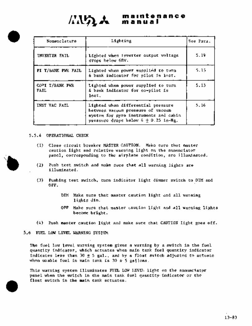
c~Cs It m -a Ilntenanceap a a a a I
Nomenclature Lighting ISee Para.
INVERTER FAIL Lighted when inverter output voltage 5.19
drops below 68V.
PI T/BANK PWR FAIL Lighted when power supplied to turn 5.15
bank indicator for pilot~is lost.
COPI T/BANK PWR Lighted when power supplied to turn 5.15
FAIL bank indicator for co-pilot is
lost.
INST VAC FAIL Lighted when differential pressure 5.16
bet~jeen vacuum pressure of vacuum
s~stem for gyro insttuments and cabin
pressure drops below 4 0.25 in-Hg.
5.5.4 OPERATIONAL CHECK
(1) Close circuit breaker MASTER CAUTION. Make sure that master
caution light and relative warning light on the annunciator
panel, corresponding to the airplane condition, are illuminated.
(2) Push test switch and make sure that all warning lights areillurn~inated.
(3) Pushing test switch, turn indicator light dimmer switch to DIM and
OFF.
DIM Make sure that master caution light and all warninglights dim.
OFF Make sure that master caution light and all warning lightsbecome bright.
(4) Push master caution light and make sure that CAUTION light goes off.
5.6 FUEL LOW LEVEL WARNING SYSTEM
The fuel low level warning system gives a warning by a switch in the fuel
quantity indicator, which actuates when main tank fuel quantity Indicator
indicatesless than 30 f 5 gal., and by a float switch adjusted to actuate
when usable fuel in main tank is 30 ;t 5 gallons.
This warning system illuminates FUEL LOW LEVEL light on the annunciator
panel when the switch in the main tank fuel quantity´• indicator or the
float switch In the main tank actuates.
13-83

n~ a~ntenancem anual
5.6.1 OPERATIONAL CHECK
(1) Close circuit breakers MAIN INV POWER, MAIN INV CONT, MASTER
CAUTION, FUEL LOW LEVEL WARN and FZ~EL QTY IND.
(2) Place the inverter switch to MAIN.
(3) Turn fuel quantity indicator test switch to MAIN and make sure
that FUEL LOW LEVEL light on the annunciator panel is illuminated
when main tank fuel quantity indicator indicates 30 -f 5 gallons.
(4) Place fuel low level test switch to TEST and make sure that FUEL
LOW LEVEL light on the annunciator panel is illuminated.
(5) Place inverter switch´• to OFF and open circuit breakers except FUEL
LOW LEVEL WARN.
(6) Set: the airplane in level position and after confirming main tank
fuel being in the same level, drain fuel until FUEL LOW LEVEL lighton the annunciator panel is illuminated. Make sure that the re-
mainingusable fuel is 30 ~t 5 gallons. If not, adjust float
switch installing position.
5.7
(I
5.8 BOOST PUMP FAILURE WARNING SYSTEM
The boost pump failure warning system gives a warning of boost pump failure
by actuating a fuel pressure switch of boost pump installed in the leading
edge of the center wing. Boost pump fuel pressure switch actuates when
boost pump discharge pressure drops below 3.2 f 0.4 psi and illuminates
L(R) BOOST PZT~IPFAIL light. This warning system illuminates L(R) BOOST PUMP
FAIL light with circuit breaker LH(RH) BOOST PUMP opened and puts out the
light with the’circuit breaker closed.
5.9 FUEL FILTER BYPASS WARNING SYSTEM
The fuel filter bypass warning system gives a warning of´•fuel filter
clogging when differential pressure between inlet and outlet of fuel filter
installed in the leading edge of ´•inner wing is 1.9 0.3 psl. or more dueto foreign material, and illuminates L(R) FUEL FIL BYPASS light.
13-84 4-1-78

C~S3 Ima P a a 8 a a a ~C 8
PtP a m’ru a I
5.10 CABIN PRESSURE WARNING SYSTEM
The cabin pressurewarning system gives a warning of low cabin pressure byactuating the cabin pressure warning switch installed on the forward section
of LH cockpit. The cabin pressure warning switch actuates when cabin
pressure drops belowatmospheric pressure corresponding to 10,000 (+0,-1000) ft. of altitude and illuminates CABIN PRESS LOW light on the annun-
ciator panel.
5´•. 11 AIR CONDITIONING FAILURE WARNING SYSTEM
The´• air conditioning failure warning system gives a warning of air condi-
tioning failure by actuating air conditioning failure~ warning pressure
switch and temperature switch installed on the air conditioning compart-ment. The pressure switch a’ctuates´• at more than 37 psi.of bleed air
pressure, inleft~ of ´•air’~conditioning system... The´•´•temperature switch
actuates at 224 f 80C~(435 f 46qF) of outlet air temperature, air condition-
ing compressor. When any of pressure switch or temperature switch actuates,
a press-to-test type air conditioning warning light ACS FAILURE (*1) on RH
switch panel, or AIR COND SYS FAIL light ("2) on the annunciator panel is
illuminated.
5.12 DEFOG AIR TEMPERATURE WARNING SYSTEM
The defog air temperature warning system gl~ies a warning of defog system
LH and RH windshield defog air outlets.
failure by actuating defog air´•temperature warning switch installed on the
Defog air temperature warning switch actuate’s when windshield defog air
outlet temperaturereaches more than 2000F (93"0) ana´•illuminat‘es DEFOG
OVER TEMP warning light on thepilot instrument panel ("1), ~the annunciator
panel (k2).
5.13 ENTRANCE DOO~ OPEN-fJARNING SYSTEM´• IThe door open warning system gives a warning of door open or imperfectlock by actuating door lock switches installed on the entrance door.
This warning sys-tem illuminates the’ ENT DOOR OPEN light on the annunciator
panel wt~en the entrance aoor is open or lock is imperfect.
5.14 HEATED WINDSHIELD ANTI-ICE TEMPERATURE WARNING SYSTEM
(Aircraft S/N 661SA, 697SA and subsequent)
.The heated, windshield anti-ice´• temperature warning system gives a warningof windshield anti-ice system failure by actuating windshield anti-ice
temperature controller installed on the lowe_r section of electronic com-
partment when temperature sensor installed on the LH and RH windshield
glass reaches 129 f~50F (5411t 30C); and by illuminating L(R)’H/W OVER’TEMPannunciator light.
*1 Aircraft S/N 652SA and 661SA
Jt2 Aircraft S/N 697SA and subsequent
13-85-6-1-79

~T´•´•
~t m a s a 19 a a a a a a
at a a a a I
5.15 TURN/BANK INDICATOR POWER WARNING SYSTEM
The turn/bank indicator power warning system illuminates push-to-test type
warning light T/B IND POWER FAIL (*1) on the instrument panel or PI(COPI)T/BANK PWR FAIL ("2) on the annunciator panel, when turn/bank indicator
is not supplied power.
5.15.1 OP~RATIONAL CHECK (*1)
(I) Close circuit breaker MASTER CAUTION.
(2) Close circuit breaker T B IND. Make sure that T/B IND POWER FAIL
light goes out.
(3) Open circuit breaker T B IND. Make sure that T/B IND POWER FAIL
Fight illuminates.
5.16 VACUUM PRESSURE WARNING SYSTEM
The vacuum pressure warning system gives a warning of vacuum pressure source
failure for gyro instruments by actuating vacuum pressure warning switch
installed on the forward section of LH cockpit.
between vacuum pressure of vacuum system ´•and cabin pressure drops below
The vacuum pr~ssure warning switch actuates when differential pressure
4~ f 0.25 inrHg: and illuminates INST VAC FAIL Light on the annunciator panel.
5;17 GENERC~TOR’FAILURE WARNING SYSTEM
The’ generator failure warning system gives a warning of generator outputfailure by actuating reverse current cutout relay installed in the LH main
junction~ box or overvoltage protecting relay installed in the RH main junc-ti’on~box and by illuminating L(R) DC GEN OUT light on the annunciator panel.
The reverse ~’curr8nt cutout relay actuates when generated voltage dropsbelow main’bus voltage and 9 to 25A of reverse current is generated in the
generator,’ and cuts generator out of main bus. The overvoltage protectingrelay actuates when generated voltage reaches more than 32 to 34V and
cuts generator out of main bus and protects the equipment from high voltage.
5. 18 FEEDER FAILURE WARNING SYSTEM
The feeder.failure warning system gives a warning of feeder failure bytripping feeder-protecting circuit breaker installed on the main junctionbox and illuminating L(R) FEEDER OUT light in the annunciator panel when
overcurrent passes through feeder. I)*1 Aircraft S/N 652SA and 661SA
*2 Aircraft S/N 697SA and subsequent
13-86

c~lt m iii a ‘u aIm a II n9fe.n a a a a
5.i9 FAII;ZjRE WARNING SYS’rE~i:
The inverter failure warning slstem giir~$ a warning of invert~r failure byactuafirig iriirerter failure war"izin~ rei~y installed on the AC power relaybbx~ of electric compartment wtze’n inverter output voltage drops and byilluminating INVERTER Fi~ILlightdn theannunciaror paneli The inverter
failure warning´• relay actuates when inveliter butput voltage drops below 68V.
5.20 INDICATING ~IGHT
5.20.1 BETA RAN%E INDICATING LIGHT
The beta range indicating light is installed on the center instrument
panel and illuminates LH(RH)´• BETA RANG~ when engine is in beta range
mode or propeller low pitch condition~. To test lamp, close circuit
breakers LH(RH) EN~ CONT and INST PANEL LIGHT and turn panel indicator
test switch to TEST. Whenindicator lightdimmer switch is turned To
DIM, indicating light´• can be´•dinwed.
5.20.2 LANDING GEAR POSITION INDICATING LIGHT
The landinggear position indicating light is a push-to-test type lightinstalled on the LH switch panel. ~It has three~lamps: -NOSE, LH and RH,and is illuminated when landing gear is in down position. To test lamp,close circuit breaker LG POS IND and push indicating iight. When
indicator light dimmer switch is turned to DIM, indicating light
can be dimmed.
5,20,3 ENGINE START INDICATING LIGHT´•
The engine start indicating light is, in the head of.engine ´•start switch
installed´•on thecenter pedestal switchpanel.and is illuminated in
engine starting.
5.20.4 MANLTAL PROPELLER DE-ICE INDICATING LIGHT
(Aircraft S/N 652SA)
This is a push-to-test tpe indicatingiight installed on the center
pedestal switch panel and is illuminated ~ilring manual operation of
propeller de-ice system. To test this lamp, close circuit breaker
RH MANPROP DE-ICE and push the light.
13-8~

CI~A ni a ii a ii I
5.20.5 FLAP POSITION INDICATING LIGHT
The flap position indicating light is a push-to-test light installed on
the flap controller, RH side’of center p~edestal. It has the four
positions of UP, 50, 200 and 400 and indicating light correspondingto flap position is illuminated. To test lamp, close circuit breaker
FLAP CONT and push the light. When indicator light dirmnerr switch
is turned to DIM, indicating light can be dimmed.
5.20.6 HEATED WINDSHIELD HI HEAT MODE INDICATING LIGHT
(Alrcraft S/N 6’61SA, 697SA and subsequent)
The heated windshield HI HEAT MODE indicating light is a push-to-testtype light installed on the instrument panel and illuminated when
heated windshield switch to ON and push the indicating light. When in-
dicatorlight dimmer switch is turned to DIM, indicating light can be
dimmed.
5.20.7 HEATED WINDSHIELD INDICATING LIGHT
(Aircraft S/N 6’61SA, 697SA and subsequent)
The heated windshield indicating light’is a push-to-test type lightinstalled on the LH overhead switch panel and LH(RH) WINDSHIELD HEAT ON
light is illuminated during operation of heated windshield .anti-icing.To test the lamp, close circuit breaker LH(RH) HEATED WINDSHIELD CONT
and push the indicating light. When indicator light dimmer switch is
turned to DIM, indicating light can be dimmed.
5.20.8 WING DE-ICE INDICATING LIGHT
The wing de-ice indicating light is a push-to-test type light.installedin the overhead switch,console and WING BOOT ON light is illuminated
during operation of wing de-ice. To test the lamp, closecircuit
breaker WING DE-ICE and push the indicating light.. When indicator lightdimmer switch is turned to DIM, indicating light can be dimmed.
5.20.9 ENGINE AIR INTAKE ANTI-ICE INDICATING LIGHT
The engine air intake anti-ice indicating light is a push-to-test type
light installed on the overhead switch console and LH(RH) ENG INTAKE
HEAT’ON light is illuminated during operation of engine air; intake
anti-ice. To test the lamp, push the indicating light. Whenindicator
light’dimmer switch is turned to DIM, indicating light can bedimmed.
5.20.10 OIL COOLERAIR INTAKE ANTI-ICE INDICATING´•L;IGHT
The oil cooler air intake anti-ice‘indicating light.is a push-to-testtype light installed on the overhead consoieand LH(RH)OIL COOLER
HEAT T)N l.ight if; -fllllmirla~cdd diirl.ng operation of cooldr air
intake anti-ice.the indicator light dimmer switch is turned to DIM, the indicating lightTo test the lamp, push the indicating light. When
can be dlnrmed.
13-88

c~s It an a II a t a a a a a a
ns an a a I
BATTERY TEMPERATURE WARNING SYSTEM
Tfie battery temperature probe consis~s of a temperature sensing element
~htained in the connecting strap whidh replaces a strap of the batteryiii the hottest area. The sensing element is connected to a quick dis-
connector mounted´•on the battery case~near the.existing batterybiinnector´•. The indicator-is a dual battery temperature read-outtype which
i~ designed to read the’temperature of two.nickelcadmium batteries in
wit~ theprobe. Two warning lights are provided: AMBER lightlabeled 1200F which illuminates if either battery temperature exceeds 1200F,~nd one RED light labeled HOT which i´•llimunates if either battery temperature~xceeds 1500F_ It is a2" indicator with test switches and battery isolate
switches.
5.20.21 REMOVAL 6INSTALLATION:OF BATTERY PROBE
CA UT ION
Makesureaircraft power is~OFF´•byturning th~’master key switch -to
the OFF position.
(1) Gain access to the battery (or batteries).(2) Disconnect battery power connector.
(3) Disconnect temperature warningconnec.tor (located’ near battery
(4) Remove battery ~cell cover.
connector).
(5) Remove 2 eachnuts attachingthe probe to the battery cells.
(6) Removenuts, washers and screws attaching connector to
battery case.
NOTE
Do notpull teflon tubing at
connector or probe strap.
(7) Install in.reverse sequence of removal.
NOTE
When installlng_ connectorseal~both~ides of: flange- with Coasf 1Pro Seal~707. o:r DOW Cd’rning 732 RTV sealant.
5.21.2 REMOVAL C INSTALLATION OF T~MPERATURE. INDICATOR
(1) :Aircr$ft potjer OFF;
(2) Loosen (1) clamp screw´•,
(4)(3) Pull indicator from’panel.Disconnect connector from back of -indicator.
(5) Install in~ reverse seque~nce of removal.
13-89

m a I a t a a a a a a
m a a a a I
5.21.3 MAINTENANCE
Inspect the temperature probe any time the battery is removed
from the aircraft for inspection or service.
(1) PROBE
Perform leakage´•check as shownin Pig. 13-25.
NOTE
Be careful not to let the test pinstouch the metal case of plug.
Perform resistance check between pins A to B and between B to
C of the temperature plugas shown in Fig. 13-25.- Check the
resistance between pin B and the pl~g metal case; this resis-
tance should be 5 megohms or higher.
NOTL
Be careful not to let the test pinstouch the metal case of plug.
If either leakage or resistance check
does not pass tests, replace the probe.
(2) INDICATOR
Calibration check per below
(a) Where possible use P601-V or ~P602 Tester (available from
Foxtronics/Tramm).(b) Refer to manufacturer’s operational handbook for use of
the’P601-V or P602 test boxes.
NOTIE
If indicator calibration is required,return to the indicator manufacturer.
13-90

maintenanceIr\ man u~ al
Simpson 260 or
I;F) 20,000 ohm/volt
3 1 test meter
Probe check
PROBE
A) "B" to "C" resistance depending on temperature
49.9 K -200F 5.5 Meg ~LFIXED
OOF 3.05 Meg~L
+320F 1.08 MegB 1750F 300 KR
S1200F 102 KI-~VARTABLE
+1500F 51.1 KrZ
f1700F 33.2 KR
C) +1900F 22.1 Kn
Resistance check
Fig 13 25
13-91
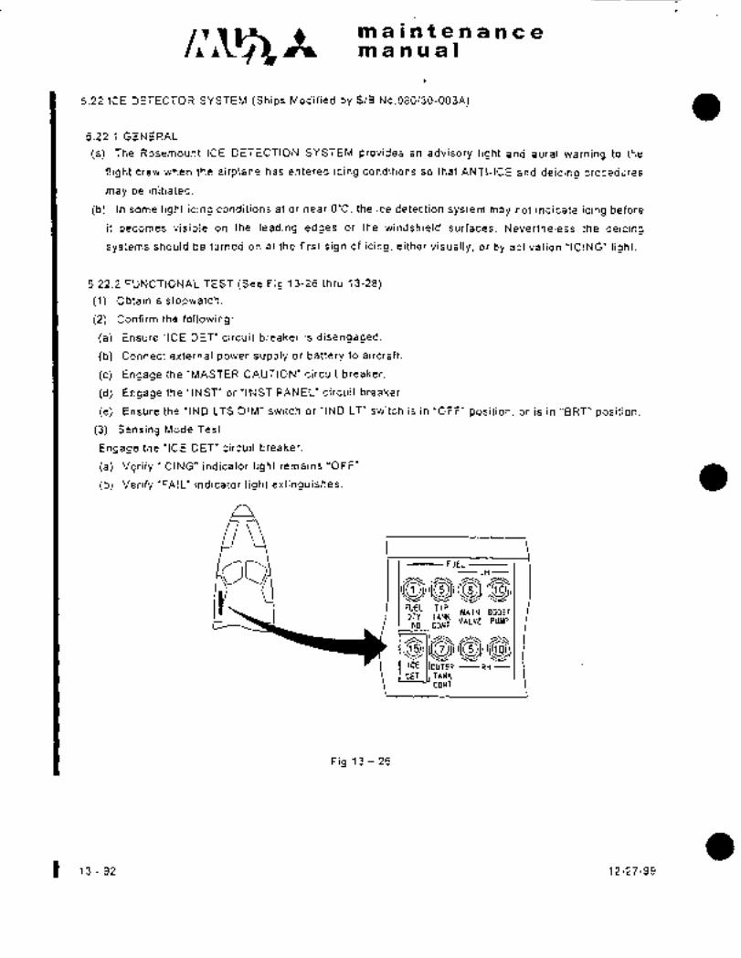
c~s-maintenanceman ual
5.22 ICE DETECTOR SYSTEM (Ships Modified by S/B No.080130-003A)
5.22.1 GENERAL
(a) The Rosemount ICE DETECTION SYSTEM provides an advisory light and aural warning to the
flight crew when the airplane has entered icing conditions so that ANTI-ICE and deicing procedures
may be initiated.
(b) In some light icing conditions at or near O"C, the ice detection system may not indicate icing before
it becomes visible on the leading edges or the windshield surfaces. Nevertheless the deicing
systems should be turned on at the first sign of icing, either visually, or by activation "ICING" light.
5.22.2 FUNCTIONAL TEST (See Fig 13-26 thru 13-28)
(1) Obtain a stopwatch.
(2) Confirm the following:
(a) Ensure "ICE DET" circuit breaker is disengaged.
(b) Connect external power supply or battery to aircraft.
(c) Engage the "MASTER CAUTION" circuit breaker.
(d) Engage the "INST" or "INST PANEL" circuit breaker.
(e) Ensure the "IND LTS DIM" switch or "IND LT" switch is in "OFF" position, or is in "BRT" position.
(3) Sensing Mode Test
Engage the "ICE DET" circuit breaker.
(a) Verify "ICING" indicator light remains "OFF".
(b) Verify "FAIL" indicator light extinguishes.
C; FUELLH
ripMAIN BOOST
TANKVALVE PUMP
IND CONT
OUTER RH
CONT
Fig 13 26
13-92 12-27-99

maintenanceIlrp manual
(4) LampTest
Press the "ICING" and the "FAIL" indicator light caps respectively.
(a) Verify respective indicator light illuminates brightly.
Turn the "IND LTS DIM" switch to "DIM" position, and press the "ICING" and the "FAIL" indicator
light caps respectively.
(b) Verify respective indicator light illuminates dimly.
(5) Detecting Mode Test
NOTE
The ice detector incorporates a probe that vibrates continuously at a specific
frequency. If ice is encountered in flight, ice adhering to the probe will result in a
change in this frequency. The frequency change will be detected and the advisory
light and aural warning will be activated. The probe is then heated automatically to
remove the ice so that a new cycle of ice accumulation and detection can start. To
simulate ice on the probe for ground tests, the vibrating probe can be grasped
between the thumb and forefinger.
WARNING
The sensing probe and strut become very hot in a few seconds when an ice
signal is turned on. Be careful to prevent burns.
Initiate the detecting mode by slowly squeezing the sensing probe between the thumb and forefinger
until the "ICING" indicator light turns on, then start the stopwatch. Release the probe when the
temperature of the probe and the strut begins to rise. Stop the stopwatch when the "ICING" indicator
light turns off.
(a) Verify that the probe and the strut heaters activate.
(b) Verify the "ICING" indicator light illuminates for 60~10 seconds, and the horn sounds for 0.5
seconds when the ’ICING" light first illuminates.
(c) Verify the "FAIL" indicator light remains "OFF".
(6) PresstoTest
Press and hold the "TEST" switch for 5-10 seconds.
(a) Verify the "ICING" indicato’r light illuminates while the switch is pressed, and the horn sounds for
0.5 seconds when the "ICING" light first illuminates.
(b) Verify the "FAIL" indicator light remains "OFF".
12-27-99 13-93 1

c~emaintenanceman ual
e%g~Q800 I I)´• O
body
~ap\lamp
TEST switch ICING indictor light
Fig 13 27
(7) Fail Mode Test
Pull the "ICE DET" circuit breaker. Verify the "FAIL" indicator light illuminates.
(8) Disengage the following circuit breakers, as applicable:
(a) "MASTER CAUTION"
(b) "INST" or "INST PANEL"
(c) "RH OVHD PANEL No.2"
~9) Remove electrical power from the aircraft.
5.22.3 Replacement of Indicator Light Lamp
(1) Turn off electrical power to the indicator light.
(2) Remove the cap from the indicator light body.
(3) Remove the defective lamp and insert a new lamp. (MS25237-327)
(4) Reinstall the cap on the indicator light body. (finger tight)
(5) Reset the electrical power.
1 13 94 12-27-99

h,
71
1’2011
w 20VDr, nIls A 28VnC IN
N
151(C11201~ ~Icl4nulle lu
O CllS2()4~)02050
2
oo, 5A
91nR (X2n~ (1203M
K STAII~S SIG.
co I´•uAssEn cAur~nEl1 03 1’MASSER CAUTIIIN
(n Y A2a
AlID I~
Z 0--------------- 02 Al3
K2n4U Ice DET
m b--------- h2 hEil 2 n~
aELnuI~ I SPAI~E 5c-FAII~ SENSE
I IHn LIT IIIM I X2
cn nS203M ~R35A X1 Y F SPI\RE
I-I 13
I I BI
N ;11
hOC K2(ISUO 204U A2 33
Al
ui X)n I IcE S16.ELINI nildi
IC~!02K) fK20:lhl
30 O 02n2M
aCr-S2T;i~ 16E nET Jo LSZO1M
J--I 1 X2.TT: 3 I(ELAY C110170 I’.ES’I rCn,
2 ´•11----" J ~ESTLI´•C O 5 1_
w ~s2onM) JtnFl
tli~II ------I c´• r.llnssls clln I a)
z IlOnN CI)I OFI- AEI.AYo J(0. 5 SEC IIELAY OEl OPER~TIOEI) o nC Return
;?5 C1ro
o
(J II I DC Returno (D6 7. 5A OI~To
ns2nsuPLT FI.T IHSI u
I)IU RIIEQSIAT LIT
C~ ICE n~’TECTOR
o
to
(II

w
too,
71
~o P201M
20VI)C OlIs n I 2evoc INC~ 17~1 Ict~ n~r I
rJ r, I znvsr. IN t-a,
CT-
o 1 I I Cz~ I FAIL]2 CP~1U3 A3II
FAIL OS204M
.JT I~A2 AlXI I K STATIIS SIG:
o.113 1MASTER CAIITION
ruY b
91on
3(o b-------- nz
(I,o osznnu
FAIL SEHSE
t+.oznnu nET
UI C~ X2
R3IIEL~Y
U
L2 ~11 n?c
3 xl u F SPAREo,
NZ
1 (I nI
nN cl 3IIIST I.T
A3N n, K2051.1
01 0204M A2 33I,
IHn LIT OIMAl
n Z XI O I ICE SIG. 8,.P)C~´• Ulnl ,c,,r
nnT I\ OFF 021)216 1120111
i----j Ictntr ,Kn =I11 IIELAY ’X2 J
DT~Oi TESTI CTEST
(D 4 _1-I.S201M
3 J TESTU
Ir IIORN
0, O hg (S203M´•e
23
C(CIIASSIS I;ND
R DC Return ;J
(D
o IIORII r.llT OFF RELAYm I~tLL-LI (0. 5 SEI: DELAY ON OPEIIATION] II ‘Oc, II ne Return
bo 7. 5A IIRT 1._-_~ CDS205M)c> DS2n5Mcs PLT FLT )NsTP
IIIII RIIEOST~T PII.LER LIT
’CF. DET~C’IOI\
N
to
co
co

CHAPTER
SUPPLENIENTS

maintenancemanual
CHAPTER XIV
SUPPLEMENTS
SUP.1 TRIM-IN-MOTION ALERT SYSTEM
i. GENERAL´•´•´•´•´•´•´•´•´•´•´•´• Sup. 1-1
2. SYSTEMDESCRIPTION Sup. 1-I
3. MAINTENANCE Sup. 1-1
4. FUNCTIONAL CHECK Sup. 1-1
5. TROUBLE SHOOTING Sup. 1-1
6. WIRING DIAGRAM Sup. 1-2
NOTE: This system is installed in accordance with MHI Service Bulletin
093/22-009 (current revision)
1-10-98 Sun. 1-i

n~3 ~i m a i_n t.e:n; a. h c a
manu a.l’
´•]1.GENERACThe Trim-in-Motion Alert System isinstalled to provide an aural alert’that the elevator trim is
operating in the airplane nose up direction with the flaps up. This sjrstem is designedspecifically to warn of an inadvertent slow down while in cruise flight: with, the autopilotengaged. The alerts will occur with increasing frequency asthe airspeed is reduced. The
Trimtin-Motion aural tone sounds only~’when the trim is opeiating in the nose up direction,and only when the flaps are UP.
2. SYSTEM DESCRIPTION
The Trim-in-Motion Alert System consists of a one way cam directly Connectdd~ to the elevator,trim cable drum assembly (PN:016A-91620) located in the center pedestal of the cockpit, a
micro switch actuatedby the one way dam, an electronic/relay equipment assembly [PN:MUB-1203´•( located in the forward cockpit area and mounted on the connection box (PN:OIS~A-88141), and an alert horn mounted in the forward ceiling panel. 28VDC discrete signais’ii;omthe micro switch are conveited to an impulse by a timing circuit and intermittent voltage is
sent to the alert horn.
3.MAINTENANCE
This system and’its ~omponents require no periodic servicing.
4. FUNCTIONAL CHECK
Proper operation ´•should be verif~ed as part~of the 100 hour check by performing fouoking.(1) Aircraft power ON
(2) With flaps UP, run elevator trim in the airplane nose up direction. Verify tone sounds.
(3) Run elevator trim in the nose down diiection. Verify no tone.
(4) Select flaps 5, run elevator trim in the nose up direction. Verify no tone:
5. TROUBLE SHOOTING
If the system fails to function properly in the functional check, conduct the following:(1) If the system fails to sound the alert horn:
(a) Cycle the "FLAP CONT’circuit breaker and verify it is IN. Verify the flap handle is in the
"UP" position.
(b) Cycle the "TRIM IN MTN’ circuit breaker (CB206M) and assure it is full IN.
(c) Listen for the micro-switch on the cable drum assembly to alternately make and break as
the trim is run in the airplane nose up direction.
(d) Verify intermittent 28V electrical power is provided to pin 5 of the equipment assembly[PN:MUZ-L203-()I when the elevator trim is run in the airplane nose up direction. (See
Fig. 14-1)
1-lb-98 Sup.l-l

c~ It: mainten ance
m a ii u a’l:~
(e) Verify operation of the Trim-in-Motion horn by removing the connector to the equipment
assembly and applying 28VDC power to socket 4 and ground~ to socket 3 of the connector
(Do not~ apply power and ground to the pins of the equipment assembly). The horn should
sound. If not,~the horn has failed,8nd needs to’be replaced.
(f) Verify operation of the flap interlock relay (I<209M) by applying 28VDC power to pin 5_and
G~and gi´•ound to~pin 7 of the equipment assembly. Place~ a voltmeter b;etweenpin 4~and
ground. Relay operation should be audible and 8SVDC~should be measured on the
voltmeter. If voltageftis not measured at pin 4, either the flap interlock relay or the Timer
Module (K208M) has failed and needs to be replaced.(2) If the alert horn sounds when the elevator trim moves in both the airplane nose up and
nose down direction:
The clutch in’the cam assembly (PN:035A-991514-105) has locked up and shouldbe
replaced.(3) If the’alert horn sounds continuously:
The i~orn Tirrier Module (PN:9514-2-0) has failed and must be replaced.
6. WIRING DIAGRAM
Fig 14-1 shows the wiring connections of the Trim-in-Motion Alert System.
*Voltage Spike is of 0.2 seconds duration-and should be measured with ´•an analog voltmeter.
:i:
Sup. 1-2 1-10-98

If maintenancemanual
TRIM-IN-MTNi ct~ W3313M22
W3312M225A- C
TRIM-IN-MOTION NO
SWITCH
TRIM-IN-MOTION
HORN TIMER MODULE I
BLU YEL 14 1 I W3314M22
ON FOR 0.2 SECS
BLK I TIMER MODULE TRIM-IN-MOTIONBRN 3 W3315M22
HORN
A3
XIAl 6
f I I I,
FLAPINTERLOCK xz i, I, I 1 ~3RELAY
ELECTRONIC/RELAY EQUIPMENT ASSEMBLY N
C123B222
UP
"I
,C~(PZ09)FROM FLAP UP LInl~e------I: j d C--------- C123822 1
SWITCH(REFER TOFLAP t~j (FOR MU-28-35 AND
CONTROL CIRCUIT) MU-28-36A(S/N 661, 3679-699))
C123C22 FLAP POSITION
CONNECTION BOX (FOR MU-2B-36A INDICATOR LIGHT
L..___.._. ._..__i (S/N 701-730))
Fig 14-1 l~im-in-motion alert system
1-10-98 Sup. 1-3/1-4

~t maintenancemanual
CHAPTER XIV
SUPPLEMENTS
SUP.B AUTOMATIC AUTOPILOT DISCONNECT SYSTEM
1. GENERAL´•´•´•´•´•´•´•´•´•´•´•´• Sup. 2-1
2. SYSTEM DESCRIPTION Sup. 2-1
3. MAINTENANCE Sup. 2-1
4. FUNCTIONAL CHECK Sup. 2-1
5. TROUBLE SHOOTING Sup. 2-2
6. WIRING DIAGRAM Sup. 2-2
NOTE: This system is installed in accordance with MHI Service Bulletin
093/22-009 (current revision)
1-10-98 Sup. 2-i

c~ ~t m, ain t: enancemanual
1.GENERAL
The Automatic Autopilot disconnect System is designed to disconnect the autopilot when the
airplane slows to 135 kias for normal operation with flaps UP. it is designed specifically to
prevent the airplane from being inadverteritly stalled by the autopilot. It Is operable only with
the flaps UP. A three second aural Olorn) and visual light alert prior to the disconnect is
provided by thiS system. The disconnect airspeed has been seiecteb to provide a largemarginabove stall. To engage the autopilot, the airspeed must be apprdximate 10 knots above the
disconnect airspeed.
2. SYSTEM DESCRIPTION
The Automatic Autopilot disconnect System colisists of an electroniclrelay equipment
assembly IPN:MU2-12b3-( )1 located in the forward cockpit area and mounted on the
connection box (PN:016A-88141), a pressure switch placed between the copilot’s pitot and
ship’s’alternate static pressure source and mounted on the equipment assembly; an alert horn
mounted in; the forward ceiling pane!, an "A/P OFF’ indicator light mounted in the windshield
center post and integrated with the disconnect circuitj of the existing autopilot. The alert
horn and "A/P OFF’ indicator light provide an aural and visual alert for 3 seconds before
disconnected. Additionally, the light remains illuminated until the pilot presses the "AP
DISC" switch on the control wheel.
S.MAINTENANCE
This system and its components require no periodic servicing.
4. FUNCTIONAL CHECK
Proper operation should be feri~edas part of the 100 hourch~ck bjr performing following.
NOTE
";yp OF" light should illuminate for approximately Isecond~and alert
horn sounds 0.5 second after.turning on Radio Master Switches.
(1) Connect the pitot-static tester to the pilot’s and copilot’s pitot tube. Vent the static
pressure to ambient.
(2) Aircraft power ON’
(3) For airplane equipped with an air driven pilot attitude gyro, disconnect engine bleed air
tube from LH or RH engine and connect an auary air pressure source~to the tube.
Apply air pressure (18 psi or above) and ensure the "INST VAC FAIL" annunciator lightgoes out and the attitude gyro isself-sustaining.
(4) For airplane equipped with an electrical driven pilot attitude gyro, ensure indicator flagdisappears and the attitude gyro is self-sustaining.
(5) Turn on inverters, and radio master switches. Autopilot master switch to ON ~if
.equipped).(6) Set the flaps to UP. Adjust the pitot pressure to an airspeed of 150 kias or greater.
Engage the autopilot. It should engage without any warnings.
1-10-98 Sup. 2-1
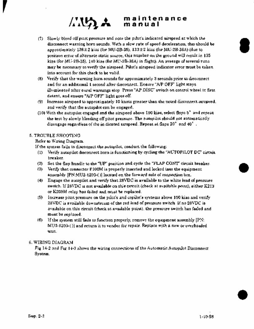
maintenancemanual
(7) Slowly bleed off pitot pressure and note the pilot’s indicated airspeed at which the
disconnect warning horn sbunds. With a slow rate of speed deceleration, this should be
approximately 128 2 kias (for MU-2B-35), 133 +2 kias (for MU-2B-36A) (due to
position error of alternate static source, this number on the ground will result in 135
kias (for MU-2B-35), 140 kias (for MU-2B-36A) in flight). An average of several runs
may be necessary to verify the airspeed. Pilot’s airspeed indicator error must be taken
into account for this check to be valid.
(8) Verify that the warning horn sounds for approximately 3 seconds prior to disconnect
and for an additional 1 second after disconnect. Ensure "AIP OFF’ light stays
illuminated after aural warnings stop. Press "AP DISC" switch on control wheel to first
detent, and ensure "A/P OFF’ light goes off.
(9) Increase airspeed to approximately 10 knots greater than the noted disconnect airspeed,and verify that the autopilot can be engaged.
(10) With the autopilot engaged and the airspeed above 150 kias, select naps 5" and repeat
the test by slowly bleeding off pitot pressure. The autopilot should not automatically
disengage regardless of the in dicated airspeed. Repeat at flaps 20" and 40"
5. TROUBLE SHOOTING
Refer to Wiring Diagram.If the system fails to disconnect the autopilot, conduct the following:
(1) Verify autopilot disconnect horn is functioning by cycling the "AUTOPILOT DC" circuit
breaker.
(2) Set the flap handle to the "UP’ position and cycle the "FLAP CON?"’ circuit breaker.
(3) Verify that connector P100M is properly inserted and locked into the equipment
assembly [PN:MUB-1203-( )1 located on the forward side of connection box.
(4) Engage the autopilot and verify that 28VDC is available to the white lead of pressure
switch. If 28VDC is not available on this circuit (check at available point), either K213
or K209M relay has failed and must be replaced.(5) Increase pitot pressure on the pilot’s and copilot’s systems above 150 kias and verify
28VDC is available downstream of the red lead of pressure switch. If no 28VDC is
available on this circuit (check at available point), the pressure switch has failed and
must be replaced.(6) If the system still fails to function properly, remove the equipment assembly [PN:
MU2-1203-( )1 and return it to vender for repair. Replace with a new or overhauled
unit.
6. WIRING DIAGRAM
Fig 14-2 and Fig 14-3 shows the wiring connections of the Autdmatic Autopilot Disconnect
System.
Sup. 2-2 1-10-98

maintenancemanual
(TBS18)ELECTRONIC/RELAY EOUIPMENT ASSEMBLY COMPUTER
I i-iL- P.PA.2A18----d L~ LH RADIO5: i BUS
YI~A/P DISC CTRL PWR(28VDC)I11 I W330SH22
A/P DISCONNECT(OUT) 1 I t---- W3301M22
A/P DISCONNECT(IN) 2 t~- W33O2M22 1 I
(TB21O)
COPILOT A/P DISC
C509C20 TO A/Pr ~I
COMPUTER
PILOT A/P DISC L...._..
i...._.._. 4
(CONTROL COLUMN) i-~GiA/P ENGAGED(EBVDC) 1 10 1 I---- W3306H22
ROLL SERVO
i..
CBDI*1B---------i ~ROH ROLLIPITCH
I´•---´•´•~ir´•´•--j´•j 7" !´•J\jENGAGE RELAY
WING CABIN
A/P OFF LIGHT
A/P OFF LIGHT(+OUT) IS I I---- W3303M22
A/P OFF LIGHT g HORN AUX GND 25
HORN(+OUT)I 14 1 I---- W3304M22
A/P OFF
HORN
LIGHT TEST(+IN) 1 17
LIGHT DIM(+IN) 1 16
AIRFRAME GROUNDI 7 1 W3317M223~11RC3A20
IEE:C
FROM IND LT TEST SWITCH
FLAP UP SIGNAL(ZBVDC) 6 W3316M22 ----1
21 IND LT DIMMING j (REFER TO INDICATOR PANELRELAY t, LIGHT CIRCUIT)
22
-iy CIFROII INO LT DIH SYITCHRCIAZO
1ND LT TEST h- iLIGIIT CIRCUI1)
(RCFER TO INDICA1OR PANEL24 RELAY
REFER TO TRIM-IN-MOTION
ALERT SYSTEM CIRCUITCONNECTION BOX
L..-.. ..-..-..-..-..-J
Fig 14-2 Automatic autopilot disconnect system
(for A/C equipped with Bendix M-4D or sperry SPZ-200 Autopilot)
1-10-98 Sup. 2-312-4

maintenancemanual
,rNa Ln
r
C OW a
X 13 gEZI O U U
4 ZT O a
a
L d O a CD 0)
n a ZZU IT N CV
O a U a
I IZ I -1
Zrr r
O v, in m E a o 4bCa O
N 3 racc a
Ch r X
Z WW =3C) PI D az z I ov,
c 00 w 5I r Lnvl
a a O
Lnr o~ C1 o s~ r 4 Y
r r r a
_W Ln Ln
Wvy U WUU
LL P LL ar r r
w w
LL LL D a a L:OCO 33
0~0YW
a~n rry,v,t
at
a o c~ ~L" 4 4J a a
B 5 4a
aO
N C1 a n ~n ~oaPr NNN
00 QIN
in IO ~nc~
N
r-N
B Br O
N \IN
4
;I m
BiiBmm 44
oa
II~u
O~I a
B BII I I lolr~ ru a II w
o uolou~-Icr vlI m--w
o m r x B B5 a cc 4 111 w
N y)a TYWLLO 44
N DLnD~ ao-J
y4r N~TWN y4Wami
XO ~7 U O~ Y I I I I I I I I I I -1 Z
CDI m 41 ~,y,
BY
4
o z 3
CL NO~W,o
,zoa:
’WN N X
Or mi~nJ Iu
Nc~WYDD
O
B ,vl
m~ruo
o--c~ rwo
Bo~nr
ocn rm mi 4 41 U
O
Bou4
m 4)1~
r
BY
r Y-3 ~z
zr wam r >-ma LnTrN a~-m o L´•
~Z N 4Wa O Or
a3
zm
w mN
cuuO uwl uLLI
Bct
x a
u N Oa aN aCL
N UW LnW ONWWw~ m~u D C
Oru~;r BOI a (ni3
a --II I I ~P: W I
W D a D a a rr 3
~El,o W ooW -IU (3)
lilr a T. WWTO
’O Ln OE
Xt B~IC3 B;cu N r: OF:5 LLY I LLY m m 4 4 x
mi Z r WL4 O m ´•~X
i oi-- O oc uaw
BC~-IP: By~ YI
u
mma
3Y I
C, (7
B-I ou
m Do 4 ,I mm w~-a
lr~4:g03
-uw JLn~n
Fig 14-3 ElectroniJrelay equipment assembly
(for A/C equipped with Bendix M-4D or sperry SPX-200 Autopilot)
Sup. 2-5/2-6
1-10-98

maintenancemanual
CHAPTER XIV
SUPPLEMENTS
SUP.3 PNEUMATIC DE-ICE MONITORING SYSTEM
1. GENERAL´•´•´• Sup. 3-1
2. SYSTEM DESCRIPTION Sup. 3-1
3. MAINTENANCE Sup. 3-1
4. EUNCTIONAL CHECK´•´•´•´•´•´•´•´•´•´•´•´•´•´• Sun. 3-1
5. TROUBLE SHOOTING Sup. 3-2
6. WIRING DIAGRAM Sup. 3-2
NOTE: This system is installed in accordance with MHI Service Bulletin
096/30-0~04 ’current revision)
1-10-98 Sup. 3-i

~3 m a i a te.n a n ce
manual
1.GENERAL
This Pneumatic De-Ice Mollltoring System is designed to inform the pilot that both wing and
tail pneumatic de-ice boot systems are receiving pressure when the ’~TING DE-ICE" switch is
selected "OW’. The wing de-ice light will illuminate only when pressure is applied to both the
wing and tail boot pneumatic lines. In automatic operation, the light will cycle approximately6 seconds on and 3 minutes off. If the wing de-ice system is selected "OW’ and the light does
not illuminate, it indicates one or both systems are not receiving pressure and icingconditions must be avoided.
2. SYSTEM DESCRIPTION
The Pneumatic De-Ice Monitoring System consists of two pressure switches located in the
pneumatic lines feeding the wing and tail boots. Since these lines are separate, a switch in
each line is needed to assure operation of both systems. In normal operation, the "WING
DE-ICE" light will illuminate only when both systems are operating properly. If the wingde-ice system is selected "OW’ and the light does not illuminate, it indicates that one or both
systems are not receiving pressure and icing conditions must be avoided. Each pressure
switch is checked for failure in the closed position during regularly scheduled maintenance
(100 hr. inspection). Note that operation of the wing boots may be visually checked from the
cockpit but that ground personnel are required to check the tail boots.
3.MAINTENANCE
As part of the normal 100 hour inspection open the drain line provided in the cross-ship de-ice
pressure line to the tail at F STA 9903 and drain any water collected. Reseal the drain plug.Water in this line is a sign of deteriorated tail de-ice boots or a leak in the pressure lines.
Repair before returning the aircraft to service.
4. FUNCTIONAL CHECK (See Fig 14-4)
(1) Verify the pressure switches have not failed in the closed position by checking for
continuity across terminals on terminal board with referring Table 14-1. These should be
open circuits.
Table 14-1 Continuity check of pressure switch
Model TB Location Continuity Check
MU-2B-35 305 Just forward the 1 and 3 2 and 3
hell-hole access door
MU-2B-36A 308 Just above the hell- 10 and Il 10 and 12
hole access door
(2) Perform normal preflight checks from the Airplane Flight Manual. Verifq´• operation of all
de-ice boots using ground personnel to observe.
1-10-98 Sup. 3-1

m a ii a t a n a n c a
manual
5. TROUBLE SHOOTING (See Fig 14-4)
(1) If the ’~WING DE-ICE" light fails to illuminate when the de-ice switch is selected:
(a) Verify at least one engine is running at 96% RPM or greater. Increase the engine power
and select wing de-ice to see if the operation is normal with increased engine power.
(b) Cycle the "WING DE-ICE" (5A) circuit breaker.
(C) Have ground personnel check the wing and tail de-ice boots for inflation and
denation when the cockpit switch is selected.
(d) If the de-ice boots are cycling normally:
a) Check wiring to the pressure switches.
b) Check operation of the pressure switches by pressurizing to 15 psi and verifying continuityacross terminals 1 and 3 (or 10 and 1 i), for the wing pressure switch and terminals 2 and 3
(or 10 and 12), for the tail pressure switch. Replace any defective pressure switch.
(e) If the de-ice boots are not cycling normally:
a) Check the regulated pressure from the de-ice distributor valve with a pressure gage.
Replace valve if the pressure is less than 15f1 psi. Conduct any other tests described
in the maintenance manual.
(2) If the "WING DE-ICE" Light illuminates without corresponding inflation of one of the
boots:
(a) Repair the de-ice boot that is inoperative.(b) Replace the pressure switch monitoring that portion of the de-ice system.
6. WIRING DIAGRAM
Fig 14-4 shows the wiring connections of the wing de-ice circuits.
Sup. 3-2 1-10-98
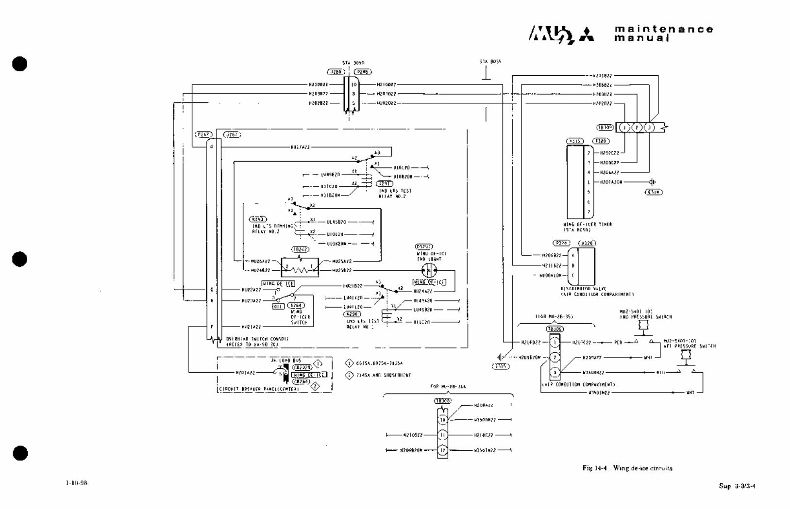
It maintenancemanual
STA 3050 STA 8035
~/(P288) I ~1211822
H21OB22 ----1 1 10 1---- H21OD22 I I i t(206B22
H203822~ 18~----H203D22 I 1 1 H203022
H202822----11 5 C----H202D22 1
T(P267)
(A315~d I HU27A22
A3 I I I I I I 1 2 t-H202C22A2
Al 3 t-H20)C22t-- U10C2O --´•---1
X1 4 t-H206A22LU49820
U1OBZON
Y2 -~j (K291 j I I I I I 1 H207A20N ----CIIIUllC2O
IND LTS TEST 5 Ii (E314)t--- UI1BZON RELAY NO.Z
A3
A2
Al~ i I i I I I I 1 7
_X1 UL45B2O I I I I I WING DE-ICER TIMERIND LTS DIMMING
RELAY NO.2 TT X2 (STA 8050)U1OL20 ----------I
--U1OKPON--------~ (A320)08262) (05297)
WING DE-ICE H206822--( A
HU26A22HU25A22I IND IIGHT
H211822--1 B
HU26B22 HU25B22
H208A20N--1 C
IWING DL-ICEI HUZ1B22A3- IUING DE-ICEI
G I I-- HU22A22 ---O A2 DISTRIBUTOR VALVE1 HU24A22
Al (AIR CONDITION COMPARTMENT)
UL49A2O --~--I3~ -2 t-- LU4LK20
H I I-- HU23A22
IOFFI LU41L20--
WING LU49B20 MU2-5401-1O1
DE-ICER (FOR nu-2B-35) FWD PRESSURE SWITCHX2
SWITCH INO LTS TEST U11C20 ---------1F I I
HU21A22 RELAY N0.1 I I I r
(78305) POVERHEAD SWITCH CONSOLE
(I H209B20N 2 H2O9A22
MU2-5401-101H210D22 1 H210C22-- RED A(REFER TO 24-50-20) AFT PRESSURE SWITCH
H201A224ilO O 6615A.6975A-713SA(E3)5~
PRH LOAD BUS
A (AIR CONDITION COMPARTMENT)U3501M22 WH
luluc DE-ICL I O 1145~ *HO SUBStOUENT3 W3500M22 RED A
2 FOR MU-2B-36ALC’RCU’T BREAKER PANEC(
08308)H2O9A22
to Ic---- W35OOM22
t---- H210D22 ----1 11 t------ H210C22
H2O9820N ----I 12 1--- W3501M22
Fig 1´•1-4 Wing de-ice circuits
1-10-98Sup. 3-3/3-4

IVIFGI
INTRO

nn u-2B-36~
\N IRING
DIAGRAM
I11I A,NU A. LDOCUMENT NUMBER MR-0219
ORIGINAL ISSU’E 1 FEBRUARY 1978
REVISION D AT E 27 A U G U T 2 9 9 9
~ITSUBISHIHEAVV IWDUSTRIES, LTD.
(LOGOCHANGE 27Aug.1999)
APPLICABLE TO AIRPLANE SERIAL NUMBER 661SA
697SA THROUGH 699SA AND 701 THROUGH 730.

MU-2B-36A
WIRING DIAGRAM MANUAL
RECORD OF REVISIONS
Retain this record in the front of the manual. .Upon receipt bf a
revision,remove the pages being revised and insert the new pages.
Enter the revision number land/or revision date), date inserted
and initials of the person incorporating the.revision.
RE3. No. fxs~RTi6ij I EY REV. 110. IHSERSIOk BY P,EY. NO. f~SEkTiOtiOR DATE DATE OR DATE DATE OR DATE DATE
nlo. 1
b
S/a7/9q ll-13-C~3
R~CORD OF REVISIONSEFFECTIVITY:. ALL
Rev´•No 1 PagelAug 1/79

RECORD OF REVISIONS
MFG REV
NO DESCRIPTION ISSUE DATE TP REV DATEI INSERTED BY
/27/99 SEE LIST OF PAGES 8/27/99 11/13/00 ATP/JB

RECORD OF TEMPORARY REVISIONS
TEMP ATP REV INSERT DATE REV REMOVE
REV NO DESCRIPTION ISSUE. DATE DATE BY REMOVED INCOR BY
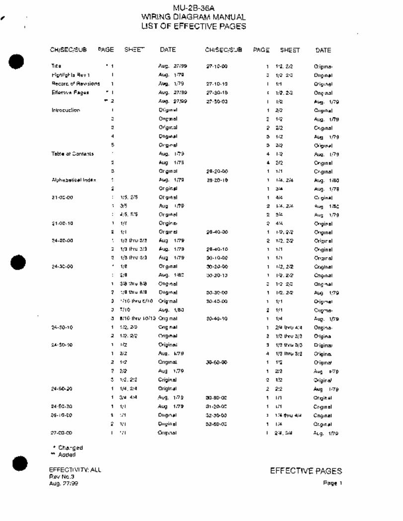
MU-2B-36AWIRING DIAGRAM MANUAL
LIST OF EFFECTIVE PAGES
CH/SEC/SUB PAGE SHEET DATE cH/sEc/svs PAGE SHEET DATE
Title ’1 Aug, 27/99 27-1 0-00 1 1/2, 2/2 Original
Highlights Rev.l i Aug. Ins 2 1/2.2/2 Original
Record of Revisions 1 Aug, ins 27-10-10 1 1/1 Original
Effective Pages Aug. 27/99 27-30-10 1 1/2, 2/2 Original
-2 Aug. 27/99 27-50-00 1/2 Aug. ins
Introduction 1 Original 1 2/2 Original
2 Original 2 1/2 Aug. Ins
3 Original 2 2/2 Original
4 Original 3 1/2 Aug. ins
5 Original 3 2/2 Original
Table of Contents 1 Aug. ins 4 1/2 Aug. ins
2 Aug. ins 4 2/2 Original
3 Original 28-20-00 1 1/1 Original
Alphabeticallndex 1 Aug. Ins 28-20-10 1/4, 214 Aug. i/80
2 Original 1 3/4 Aug. 1/79
21-00-00 1 1/5, 2/5 Original 1 4/4 Original
1 3/5 Aug. Ins 2 1/4.2/4 Aug. 1/80
1 4/5,5/5 Original 2 3/4 Aug. Ins
21-00-10 1 1/1 Original 2 4/4 Original
2 1/1 Original 28-40-00 1 1/2, 2/2 Original
24-20-00 1 1/3thru3/3 Aug. ins 2 1/2,2/2 Original
2 1/3thru3/3 Aug. ins 28-40-10 1/1 Original
3 1/3thru3/3 Aug. 1/79 30-10-00 1 1/i Original
24-30-00 1 l/e Original 30-20-00 1 1/2, 2/2 priginal1 2/8 Aug. 1/80 30-20-10 1 1/2, 2/2 Original
1 3/8thru8/8 Original 2 i/2,2/2 Original
2 1/8thru8/8 Original 30-30-00 i 1/2, 2/2 Aug. ins
3 1/10thru6/10 Original 30-40-00 1/1 Original
3 7/10 Aug. 1/80 2 1/i Original3 8/l0thru 10/10 Original 30-40-10 1 1/4 Aug, Ins
24-30-10 1 1/2,2/2 Original 1 2/4thru4/4 Original
2 1/2,2/2 Original 2 1/3thru3/3 Original
24-50-10 1 1/2 Original 3 1/3thru3/3 Original
1 2/2 Aug. Ins 4 1/3thru3/3 Original
2 i/2 Original 30-60-00 1 1/2 Original
2 2/2 Aug. 1~79 1 2/2 Aug. 1~79
3 1/2,2/2 Original 2 1/2 Original
24-50-20 i 1/4,2/4 Original 2 2/2 Aug, 1/79
1 3/4, 4/4 Aug. ins 30-80-00 1 1/1 Original
24-50-30 1 1/1 Aug, ins 31-20-00 1 1/1 Original
26-10-00 1 1/1 Original 32-30-00 1 1/4 thru 4/4 Original
2 1/1 Original 32-60-00 1 1/4 Original
27-00-00 Original 1 2/4,3/4 Aug. ins
ChangedAdded
EFFECTIVITY: ALL EFFECTIVE PAGESRev No.3
Aug.27/99 Pagel

MU-2B-36A
WIRING DIAGRAM MANUAL
LIST OF EFFECTIVE PAGES
CH/SEC/SUB PAGE SHEET DATE CH/SEC/SUB PAGE SHEET DATE
32-60-00 1 4/4 Original
2 114 Original
2 2/4 Aug. 1/79
2 3/4,4/4 Original
33-10-00 1 1/5 thru 5/5 Original
33-10-10 1 1/1 Original
33-1 0-20 1 1/1 Aug. 1/79
2 1/1 Aug. 1179
33-20-00 1 1/3 thru 3/3 Original
33-40-00 1/2,2/2 Original
33-40-10 1/1 Original
33-40-20 1 Original
33-40-30 1 1/1 Original
34-20-00 1 1/1 Original
2 1/1 Original
36-20-00 1 1/1 Original
37-20-00 1 1/1 Original
52-1 0-00 1 1/1 Original
52-70-00 111 Original
61-20-00 1/1 Original
73-30-10 Original
2 1/1 Original
3 111 Original
76-00-00 1 1/5 Original
’12/5 Aug. 27/99
1 3/5thru5/5 Original
77-00-00 1 115, 2/5 Original
1 3/5 Aug. 1179
i 4/5,5/5 Original
ChangedAdded
EFFECTIVITY: ALL EFFECTIVE FAG ESRev No.3
Aug.27/99 Page2

MU-2E-36A
~IRING DIAGRAM M~NUAL
T,9BLE OF C~NTEN7S
Chapter No,
Section of
Subject Sub~ect Page Sheets Effectivity
AIR CONDITIONING CONTROL 21-00-00 1 5 661SA, 697Sk-730S~
DEFOG OVERTEMP 21-00-10 1 1 661SA
DEFOG OVERTEMP 21-00-10 2 1 697SA-730Sk
AC POWER SOURCE 24-20-00 1 3 661SA, 697SA-710SA
AC POWER SOURCE 24-20-00 2 3 711SA-722SA
AC POWER SOURCE 24-20-00 3 3 723SA-730SA
DC POWER SOURCE 24-30-00 1 8 661SA
DC POWER SOURCE 24-30-00 2 8 697SA-7’13SA
DC POWER SOURCE 24-30-00 3 10 714SA-730SA
BATTERY OVERTEMP WARNING 24-30-10 1 2 661SA
BATTERY OVERTEMP WARNING 24-30-10 2 2 697SA-730SA
COCKPIT RELAY BOX 24-50-10 1 2 661SA
KPIT RELAY BOX 24-50-10 .3 2 718SA-730SAKPIT RELAY BOX 24-50-10 2 2 697SA-717SA
OV´•ERHEAD SWITCH CONSOLE 24-50-20 1 4 661SA, 697SA-730SA
OVERHEAD AUXILIARY SWITCH PANEL 24-50-30 1 1 661SA, 697SA-730SA
ENGINE FIRE DETECTING CIRCUIT 26-10-00 1 1 661SA, 697SA-713SA
ENGINE FIRE DETECTING CIRCUIT 26-10700 2 1 714SA-730SA
CONTROL COLUMN 27-00-00 1 1 661SA, 697SA-730SA
TRIM AILERON CONTROL 27-10-00 1 2 661SA, 697SA-713SATRIM AILERON CONTROL 27-10-00 2 2 714SA;730SA
TRIM AILERON POSITION INDICATION 27-10´•´•´•10 1 1 661SA, 697SA-730SA
STALL WARNING SYSTEM 27-35-10 1 2 661SA, 697SA-730SA
FLAP CONTROL 27-50-00 1~ 2 661SAFLAP CONTROL 27-50-00 2 2 697SA-700SAFLAP CONTROL 27-50-00 3 2 701SA~713SAFLAP CONTROL 27-50-00 4 2 714SA-730SA
MAIN TANK FUEL CONTROL 28-20-00 1 1 661SA, 697SA-730SA
EFFECTIVITY: ALL
Rev No 1 CONTENTSAu~ 1/79 Page 1

1\1U-2~-36A
WIRING DT~GRAM MANUAL
TABLE OF CONTEMTS
Chapter No.Section of
Subject Subject Page Sheets Effectivity
FUEL TRANSFER CONTROL 28-20-10 1 4 661SA, 697SA-713SAFUEL TRANSFER CONTROL 28,20-10 2 4 714SA-730SA
FUEL QUANTITY INDICATION ......1...... 28-40-00 1 2 661SA, 697SA-713SAFUEL QUANTITY INDICATION 28-40-00 2 2 714SA-730SA
FUEL FILTER BYPASS/BOOST PUMP FAIL 28-40-10 1 i 661SA, 697SA-730SA1
~ING DE-ICE 30-10-00 1 1 661SA, 697SA-730SA
ENGINE AIR INLET ANTI-ICE 30-20-00 1 2 661SA, 697SA-730SA’
OTL COOLER INLET ANTI-ICE 30-20-10 1 2 661SA, 697SA-713SAOIL COOLER INLET ANTI-ICE 30-20-10 2 2 714SA-730SA
PITOT TUBE STATIC PORT ANTI-ICE 30-30-00 1 2 661SA, 697SA-730SAi
WINDSHIELD WIPER CONTROL 30-40-00 1 1 661SAWINDSHIELD WIPER CONTROL 30-40-00 2 1 697SA-730SA
HEATED WINDSHIELD ANTI-ICE CONTROL´• 30-40-10 1 4 661SAHEATED WINDSHIELD ´•ANTI-ICE CONTROL 30-40-10 2 3 697SA-713SAHEATED WINDSHIELD ANTI-ICE CONTROL´•... 30-40-10 3 3 714SAHEATED WINDSHIELD ANTI-ICE CONTROL 30-40-10 4 3 718SA-730SA
FROPELLER DE-ICE CONTROL.........1...
30-60-00 1 2 661SA, 697SA-714SAPROPELLER DE-ICE CONTROL 30-60-00 2 2´• 718SA-730SA
I´•JING ICE INSPECTION LIGHT 30 -80 -00 1 1 661SA, 697SA-730SA:
OUTSIDE AIR TEMPERATURE INDICATION 31-20-00 1 661SA, 697SA-730SA:
LANDING GEAR CONTROL 32-30-00 1 4 661SA, 697SA-730SA
LANDING GEAR POSITION INDICATION 32-60-00 1 4 661SALANDING GEAR POSITION´•~NDICATION 32-60-00 2 4~ 697SA-730SA
INSTRUMENT SWITCH PANEL L,IGHTING 33-10-00 1 5 661SA, 697SA-730SA
TRIM INDICATOR LIG.L(TING 33-10-10 1 1 661SA, 697SA-730SA´•
EFFECTIVITY: ALL CONTENTS
Rev No 1 Page 2
Aug 1/79

MU-2B 36A
WIflING DI´•AGRA~ MANUAL
TCIBLEOF CONTENTS
Chapter No.
Section of
Subject Subgect Page Sheets´• :Eff~ctSvi ty
MASTER CAUTION WARNING LIGHTING 33-10-20 1 1 661SA, 697SA-713SAMASTER CAUTION WARNING. LIGHTING 33-10´•-20 2 1 714SA-730SA
ROOM LIGHTING 33-20-00 1 3 661SA, 697SA-730SA
NAVIGATION LIGHTING 33-40-00 1 2 661SA, 697SA-730SA
FUSELAGE LANDING LIGHTING 33-40-10. ´•1 1 661SA, 697SA-730SA
TIP TANK TAXI LIGHTING .........j.?..!. 33-40-20 ’1 1 661SA, 697SAi730SA
STROBE LIGHTING................r ..ii i´•.. 33-40-30 1 1´• 661SA; 6~7SAc730SA
TURN 3 BANK INDICATOR 34-20-00‘ 1 :1 661SATURN BANK INDICATOR 34-20-00 .2 1 697SA-730SA
(I~CABIN PRESSURE WAfjNING SYSTEM 36-20-00 1 1 661SA, 697SA-730SA
VACUUM PRESSURE WARNING SYSTEM 37120-00 1 1 66´•1SA, 6976A-7jOSA
DOOR SEAL 52-10-00-. 1 1 661SA, 697SA-730SA
DOOR LOCK WARNING 52-70r00 1 1 661SA, 6975A-730SA j
PROPELLER SYNCHROPHASER CONTROL ,.j~j.. 61-20-00 1 1 ~66iSA, 697SA-730SA
FUEL PRESSURE INDICATION 73-30-10 1 1 661SA
FUEL PRESSURE INDICATION 73-30-10 2 1 697SA-713SA
FUEL PRESSURE INDICATION i............73-30-10 3 1 714SA-730SA
ENGINE 3 PROPELLER CONTROL 76-00-00 1 5 661SA, 697SA-730SA
ENGINE INSTRUMENT INDICATION ...’.’;I;c. 77-00-00 1 5 661SA, 697SA-730SA
CONTENTS
Page 3
EFFEC~IVIIY:´• ALL
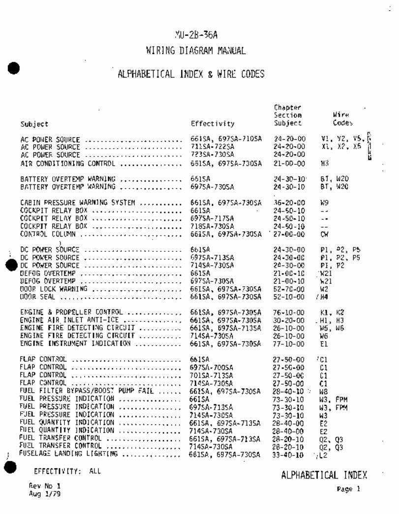
MU-2B-36A
WIRING DIAGRAM MANUAL
ALPHABETICAL INDEX 8 WIRE CODES
ChapterSection Wire
Subject Effectivity Subject Codes
AC- POIIER SOURCE 661SA, 697SA-710SA 24-20-00 V1, V2, V5,AC POWER SOURCE 711SA-722SA 24-20-00 X1, X2, X5
AC POWER SOURCE 723SA-730SA 24-20-00
AIR CONDITIONING CONTROL 661SA, 697SA-730SA ´•21-00-00 ’H3
BATTERY OVERTEMP-WARNING 661SA :24-30-10´• BT, W2O
BATTERY OVERTEMP WARNING 697SA-730SA 24-30-10 BT, W2O
CABIN PRESSURE WARNING SYSTEM 661SA, 697SA-730SA 36-20-00 W9COCKPIT RELAY BOX 661SA 24-50-10COCKPIT.RELAY BOX 697SA-717SA 24-50-10COCKPIT- RELAY BOX- 718SA-730SA 24-50-10CONTROL COLUMN 661SA, 697SA-730SA´• ’27-00-00 CW
OC PO#ER S)OURCE 661SA 24-30-00 P1, "2, P5
DC POWER SOU RC E.t..........l
697SA-713SA 24-30-00 P1, P2, P5
DC POWER SOURCE ..´•.t 714SA-730SA 24-30-00 P1, P2
DEFOG OVERTEMP 661SA 21-00-10 :W21´•DEFOG OVERTEMP 697SA-730SA 21-00-10 W21DOOR LOCK WARNING 661SA, 697SA-730SA 52-70-00~ ´•W2DOOR SEAL 661SA, 697SA-730SA 52-10-00 (H4
ENGINE PROPELLER CONTROL 661SA, 697SA-730SA 76-10-00 K1, K2
ENGINE AIR~´•INLET ANTI-ICE 661SA, 697SA-730SA 30-20-00 .~H1, H3ENGINE FIRE DETECTING CIRCUIT 661SA, 697SA-713SA 26-10-00 W5, W6ENGINE FIRE DETECTING CIRCUIT 714SA-730SA 26-10-00 W6ENGINE INSTRUMENT .INDICATION 661SA, 697SA-730SA 77-10-00 El
FLAP CONTROL 661SA 27-50-00 ,C1FLAP CONTROL 697SA-700SA 27-50-00 C1FLAP CONTROL 701SA-713SA 27-50-00 C1FLAP’ CONTROL 714SA-730SA ´•27-50-00 C1FUEL FILTER BYPASS/BOOST PUMP FAIL 661SA, 697SA-730SA 28-40-10:’-- W8FUEL PRESSUR~E INDICATION 661SA 73-30-10 W3, FPMFUEL PRESSURE INDICATION 697SA-713SA 73-30-10 W3,: FPMFUEL PRESSURE INDICATION 714SA-730SA 73-30-10 W3FUEL QUANTSTY INDICATION 661SA, 697SA-713SA 28-40-00 E2FUEL QUANTITY INDICATION 714SA-730SA 28-40-00 E2FUEL TRANSFER CONTROL-.,....; 661SA, 697SA-713SA 28-20-10 42, 43FUEL TRANSFER CONTROL 714SA-730SA 28-20-10 02, 03
CFUSELAGE LANDING LIGHTING 661SA, 697SA-730SA 33-40-10~ ‘IL2
EFFECTIVITY: ALLALPHABETICAL INDEX
Rev No 1Page 1
Aug 1/79

~tr-2B 3SA
ALPHPI3ETICFL INTIEX a CODESChapterSection Wire
S~bject Effecti v i ty Subject Codes
HEATED WINDSHIELD ANTI-ICE CONTROL 661SA 30-40-10 H5, H~S
HEATED WINDSHIELD ANTI-ICE CONTROL 697SA-713SA 30-40-10 H5, HWS
HEATED WINDSHIELD ANTI-ICE CONTROL 714SA 30-40-10 H5
HEATED WINDSHIELD ANTI-ICE CONTROL 718SA-730SA 30-40-10 H5
INSTRUMENT SWITCH PANEL LIGHTING 661SA, 697SA-730SA 33-10-00 L4
LANDING GEAR CONTROL ~61SA, 697SA-730SA 32-30-00 G1LANDING GEAR POSITION INDICATION 661SA 32-60-00 G1LANDING GEAR POSITION INDICATION 697SA-730SA 32-60-00´• G1
MAIN TANK FUEL CONTROL 661SA, 697SA-730SA 28-20-00 QIMASTER CAUTION WARNING LIGHTING 661SA, 697SA-713SA -33-10-20 P12MASTER CAUTION WARNING LIGHTING 714SA-730SA 33-10-20 W2
NAVIGATION LIGHTING..i 661SA, 697SA-730SA 33-40-00 L1
OIL COOCER INLET ANTI-ICE 661SA, 697SA-713SA 30-20-10 OCOIL COOLERINLET ANTI-ICE 714SA-730SA 30-20-10 H6 aOUTSIDE AIR TEMPERATURE INDICATION 661SA, 697SA-730Sk 31-20-00 D1OVERHEAD AUXILIARY SWITCH PANEL 661SA, 697Sk-730SA 24-50-30OVERHEAD SWITCH CONSOLE 661SA, 697SA-730SA 24-50-20
PITOT TUBE STATIC PORT ANTI-ICE 661SA, 697SA-730SF~ .30-30-GO F3
PROPELLER DE-ICE CONTROL 661SA, 697SA-714SA 30-60-00 ´•Hli HD1PROPELLER DE-ICE CONTROL 718SA-730SA 30-60-00 HIPROPELLER SYNCHROPHASER CONTROL 661SA, 697SA-730SA 61-26-00 K2, K7, K9
ROOM LIGHTING 661SA, 697SA-730SA 33-20-00 L3
STALL WARNING SYSTEM 661SA, 697SA-730SA 27-30-10 W4
STROBE LIGHTING 697SA-730SA´• 33-40-30 L7
TIP TANK TAXI LIGHTING 661SA, 697SA-730SA 33-40-20 TTL, L8TRIM AILERON CONTROL 661SA, 697SA-713SA 27-10-00 C2TRIM AILERON CONTROL 714SA-730SA 27-10-00 C2TRIM AILERON´•POSITION INDICATION 661SA, 697SA-730SA 27-10-10 03TRIM INDICATOR LIGHTING 661SA, 697SA-730SA 33-10-10 L5.TURN BANK INDICATOR 661SA 34-20-00 ~F1TURN BANK INDICATOR 697SA-730SA 34-20-00 F1
VACUUM PRESSURE WARNING SYSTEM 661SA, 697SA-730SA 37-20-00 W1
WINDSHIELD WIPER CONTROL 661SA 30-40-00 -MIWINDSHI~LD WIPER CONTROL 697SA-730SA 30-40-00 M1WING DE-IC~ 661SA, 697SA-730SA 30-10-00 H2blING IC INSPECTION ~IGHT 66~SA, 697SA-730SA 30-80-00 L1
EFFECTIVITY: ALL LILPHABETICAL I NDEX
Page 2

MU-2B-3~A
WIP,ING DIBGRA~ MANUAL
INTRODUCTION
ATA CHAPTERS
The wiring diagramf in this manual are basicall’y organited aci~ording to theATA Specification 100. The numbering consists of three sets of two numbers.
Example for 24-30-10 would be
IElectrical Power (ATA Chapter)
1 DC Generation (ATA Sub-System)24 30 10 ----Battery Overtemp (Mit;subishi) Sub-System of
DC Generation
Sub-Systemsare not always broken out per ATA Code, for instance 24-30-00includes -30 (DC Generation), -40 (Externa1 Power) and -50 (Load Distribution).When there is no specific Sub-System listing such as External Power, refer to
other diagrams within the chapter.
PAGE NUMBERS SHEET NUMBERS
Page numbersstart at 1 for each ATA Chapter number, Sub-System number and
Sub-Sub-System number.
The page number is used to separate changes in effectivity with (Page 1) repre-senting the original configuration and (Page 2) and on showing changes for sub-
sequent aircraft. The page number will represent the block of serial numberslisted the title of the page. Additional serializations may
appear on the page but will have no effect on the page number.
The majorityof the diagrams are broken down into segments which are identified
by sheet numbers such as (Sheet 2/5)which means sheet 2 of 5.
INDIVIDUAL COMPONENT OR WIRESERIALIZATION
Minor changes such as an added wire or reidentification of a component will
normally be shown as aart of the basic diagram but will be flagged by a
diamond-shaped code 1 The serialized effectivity will be shown on eachsheet whenever a code iS used and´•the codewill remain constant for all sheets
applicable to a particular page.
When tracing a coded wire O on a diagram, make sure that the terminal pointor end of traced portion is coded the same.
EFFECTIVITY: ALL Page 1
INTRODUCTION

f’iU-2B-368
WIRIMG DIAGRA~ MA~UAL
INTRODUCTION
WIRE IDENTIFICATION
All wires are normal:ly identifiedwith a letter and number code unless the wire
is less than’six inches in length. The code is eitherprinted, stenciled or bandedto each wiresegment between two points in a circuit. The letter number codewill identify the wire’to a system and will give the wire gage.
The following wire identification and explanation is a typical example.
N ~SA)-------San Angelo Modification
Wire
Numberi Wire
Segmentle T_wire Function
Wire Gage
Circuit Function
CIRCUIT FUNCTION
Circuit Function codes are listed (next page) and will serve as an aid when trying todetermine thep~rpose of a particular wire in the aircraft. These codes are
also listed bes~de the Alphabetical Index for association with each diagram.
The letter´•code is a general designation and the’number will refer to a particularcircuit.
WIRE SEGMENT
The wire segment letter identifies each segment (portion of a wire between two
connecting points) and will normally start with "A" on the segment connecting tothe power source, signal source or ground. Each connecting.segment will be
assigned the next letter alphabetically. Letters "I" and "0" are not used.
WIRE SIZE
Numerical digit(s) stating the wire gage for each segment. Coaxial cables andthermocouple wires will not be identified as to wiresize.
WIRE FUNCTION
The last alphabetical letter:further identifies the wire segment function. The
ground or conductor material letter indicates the following:
Letter Indicates
N That the wire completes a ground circuit to ground.
(SA) Sa´•n Angelo Modification or addition.
T That the wire is in a thermocouple circuit.
(AL) Alumel wire in the segment INTRODUCTION(CR) Chromel wire in the segment.
Page 2EFFFCTTVT TV t Al I

MU-2B-36A
WIRING DIAGRAM MANUAL
INTRODUCTION
CIRCUIT FUNCTION CODES
CIRCUIT CIRCUIT FUNCTION/SYSTEM CIRCUIT CIRCUIT FUNCTION/SYSTEMFUNCTION FUNCTIONCODE CODE
C Flight Controls M Miscellaneous ElectricC1 Flap Control M1 Windshield Wiper ControlC2 Trim Aileron Control M2 Toilet
M3 Cigar LighterC1J Control Wheel
P DC Power
D Instruments (Except Flight and Engine) P1 DC PowerD1 O.A;T., Outside Air Temperature P2 DC Power
93 Trim Aileron Position Indication P5 DC Power
E Engine instruments Q Fuel and OilEl Engine Instruments Q1 Plain Tank Fuel ControlE2 Fuel guantity 92 Fuel Transfer Control
43 Fuel Transfer ControlF´• ’Flight Instruments
Fl Turn and Bank Indication V DC Power and DC Control for AC
F3 Pitot and Static Port Anti-ice V1 AC Power SourceV2 AC Power Source
G Landing Gear
G1 Landing Gear Control X AC Power
GI Landing Gear Position Indication X1 AC Power SourceX2 AC Power Source
H Heating, Cooling and Anti-Ice
H1 Engine Anti-Ice, Propeller De-Ice W Warning and Emergency (Master Caution)H2 Wing De-Ice W1 Vacuum Pressure Warn
H3 Air Conditioning W2 Door Lock Warn, Master Caution
H4’ Door Seal W3 Fuel Pressure Indication/WarnH5 Heated Windshield Anti-Ice W4 Stall Warn
H6 Oil Cooler Inlet Anti-Ice W5 Engine Fire DetectW6 Engine Fire Detect
K Engine and Propeller Control W8 ~Fuel Filter Bypass/Boost Pump Failure
K1 Engine and Propeller Control W9 Cabin Pressure Warn
K2 Engine and Propeller Control W2O Battery OvertempK7 Propeller Synchrophaser W21 Defog OvertempK9 Propeller Synchrophaser.
BT Battery OvertempL Lighting FPM Fuel Pressure Meter
L1 Navigation Lights OC Oil CoolerL2 :Fuselage Landing Lights HWS Heated WindshieldL3 Room Lights TTL Tip Tank Light (Taxi)L4 Instrument and Switch Panel Lights P PowerL5 Trim´•Indication LightsL6 Instrument LightsL7 Strobe LightsL8 Tip Tank Taxi Lights
I~TRODUCTION
EFFECTIVITY: ALL Page 3

MU-2B-36A
WIRING DI~GRAM MANU~L
ELECTRICAL SYMBOLS
CircuitBattery7 rConductors Termin;il
breaker
´•11´•-111- i) JJpu,vh SVwitich =OScrew Solder
Pull Plug
Coaxial
cable
Wiret t
Disconnect
-_g~--
.Wire crossed. Wire crossedPlug and splice
(Not connected) (connected) receptacle
--8- --t~t-- d ---CC3~--~wisted Shielded Grounded Feed through-wires wires shield wire terminal CO""ectiori
Contacts------7 Fuse
block
Term‘inalMaintained Nlomentaty
i block
LightsGround 7 Heater
color code R~ Red
W.. White
G..Green_
Y..Yellow
iIndicator Incande-Pitot tube light(push scent
to test)
IVliscellaneous
Positive
Partitem(AIO~ External
O0~5)
Horn power EquipmentNumberNegative receptacle
Mechanica~ Slip ring Bus bar
linkage .,d brush Temperature Indic ator
assembly sensor
INTRODUCTION
EFFECTIVITY: A~C Page 4

MU-2B-6A
WIRING DIAGRAM MANUAL
ELECTRICAL SYMBOLS
Resistors Diode
Fixed AdjustableVariable
Relays
-ra_I
-r ’Tp_
~1s, P, D, T 8, P. D, T D, P, n, T D,P,D, T
(Double .Double
contatts) contacts)
Switches Shunt
.Toggle or slide
Ib
LsllL´° Ib~UGo_LP---‘b-
s~ P. S~T S. P, D, T D, P, D, T
Limit (R/Iechanically actuated)~r, IrThermocouple
-h_
s. P. S.T D, P~ D,T 8, P, D.T
Push-5
II
s_qqT I TransformerD, P, D, T
Miscellaneous
-o~b-- I/E-r
FloatRotary Pressure Auto
transformer
INTRODUCTION
EFFECTIVITY: ALL Page 5

CHAPTE R
AIR
CONDITIONING

I GriiS) /I e21~ B214 PZ14*l CL-I
H37/At2-´•gR( ~---´•GL-L --------T1~:L-/L 2 ~---+-1 (H ns,a~ 2 2
WJPAtZ CL-5 --;-81 JL -21
IOoB~Lo ’1III C----CG~P
IlsILBeo 1´•d cc -~*´•l------------Cc-14 lh I~s,LAPa
11908611 LG-I9
38820 CG-CT Cb-I5 Hdn A ZD
I634882
<K~501. L-~
nal7a20 )E11568220 -´•--(BF( (L---PG-4 n~sen 20
JL’bZD ,RI I CL-bl-tCt---( I-----)_
H301F20 I ´•C’~nnro
~305FZD-----´•PSi ~---Cb.lZ L tb-I2: 1
.dJ I ´•I
;HSO(BtD-----dBtl C---CD-II "’L CG- II1 ~-r T 1 IY;~-- H7OQAZO
11399020 JL-7
llJllBeO--133~ C---LJ-r CJ´•2 ~-C-$-CC--([dl usll~zo
H317820 1171 1-CJ-J
IIII .J I ’CJ-3jCJ-4 ULL 07-4
HSIOBLO 03- I ;-C-C-( let nsIoAzo
BZe B JL-2 J~ -2H994922
H14)/1 LD--(ill L-b
:IH340A20 36-i JL-5
CL-1 U1 H3CBAZO(P2/o~ 0
HsoBAeo
to ,U, CF-I CF-I
~Rf8Qv´• Hso~Jzo
z~ 13’-CI1 ~-´•c-C´•14 d
HJ9~8ZO9
I
erll r-w
u CX-4
06-Ce-260 0
(RLAT c-rS~ HIOIM 20 O L
I CK-J 0 11969A 20
i!H)olEZO ~--j
ANNUNCIATO~ i2qd
n7dlltO 75
1H LD1~ IYS
SLEEO AIL Y~L
I cacu~TBREA KER PAAIEL _iM
O S/N 66156 O5/N 66156, 69751 thru IlfsA
O S/N 69751 and Subrequent S/N 71451 end Subsequent
5/11 709SA thtu 713SA also S/)l per d~ lP modlCled per SR007/21-001
S/N 661SA, 697SA´•thru 70856 not mojili.ed per SI1007/21-001
AIR CONDITIONING CONTROL21-00-00
Aircraft S/N 661SA, 697SA -730SA
Page 1
Sheet 1/5

28 HbUbOlLt(ng~
Hal~tAe?
liY cAB,N A,nscLec raa
2255 04/2
21
WSII e20 2 020HJIOC20
0\1------ HJI)DA 20 I I
yxu~ial 2, IIIIPIPLO ~STA e16~)
lil 1 --"’7~u/bn 20
r*a~ Al4
)9c~ *´•-H3fPBL13-´•-~
(OF~ SZIZC~LP
20 U ´•:-H137C20 CIIQU AIRH915A20 Sw~rcr,522
HJ39)120 RMT SILlctWBNY a,~
SELEcs: OvFnlDE ~n/- llJJ8820 O)LIUDZ SN.
ZDrsetsu, HJ9911g0 1(11220
E(. Lu ~L =r~c+o Su ~L´•´•- H~OAtP--
CAIU~ A~L
Bn3uF20 I m
FL H3422r, !’Y4
HJOSeLO05242
LHTJ
H304bZO- /orFd ~T1I Ili~ HJ~on20
HJunto-HluoronJ04AZ~
2111
naQILILo
I~ pI
I6
´•C_ ~--´•J i~ I I I IHJI)ELO S:
KID~DIO 8338220 --)2-
H3J%C20´•1seD-sA
rl3lOAZo cwUlla rrwHj100PO 5bUe 011.)01
Hin7BZO--*2~.-Wa37EZo--- sw,rse
I-, S,,CHW Al4TCAYIR87´•SA
c
I nso7AHnsin I(( ~(oasl´•sa39 30 IJ 20
H3OIB
CS2fb) 11341520--1) ´•--HJ4/82916,
pCLIBIY lp~
~J01J20ousLb 7 9- Ha438PO
.SWITCH
’;EH367A20 0-------~_ (02201) O301MZ4 AC5.
I
-H36922o OIN~lcAron
L ~RH JYIIW RINEL_ 8320(
CP"1~
0 ’42120--1 be’ H~a,ezO----I8
(2 127)2127
<A41d)LN 8LZCD AIR
SNor-w~i YALV~LH W)UB Dl~t
IHIST* 2250)
M O S/N 661SA
S/N 709SA thru 713SA also S/n per Q~ 1P modified per SR007/21-001 O S/N 661SA, 69752 thru 71352
S/N 661SA. 697SA thru 708SA not modfrled per SR0(17!21-001 S/N 71452 and Subsequent
O S/N 66152, 69752 Ihtu 70652
S/N 707SA and Subsequent
AIR CONDITIONING CONTROL 21-00-00Aircraft S/N 661SA, 697SA´•.- !30SP1´•
Page 1
I Sheet 2/5
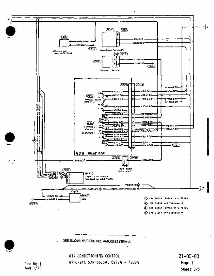
/i/
~AZJZ)
9348Rs8ZB22
SHUT-OFF M)LY5 /h(Z~Tp2.
cLs~813’
(res~
THPRMAI S~rrH
(Je4aUBlbE2
.11HIILCLO
I
(K231) 81~801H37d020 1ComaoL aaLnv ea ,.iahF-- 02
SC H379 D 113740
[mnxuAL) 188
EEm~
~-r I I I ~aBOC 20 F1380
995588
~cnlscs
C9NrROL HSO10
8PLAY Hsl-’ HBQICiFOI H301Feo
[WARN/AIG)~N ~i *h-~H?IO1 L~ ~Jol
95tE
H3s7 0 H357C~e ;r~c(5 ~’4 A201´•I(~ )I H314 8289 c´•L
~BLAT B9C(
Csess),m (0288)
´•I
(8259) STA 5090
837395P CLCILIY6~rreT89c1IU79CZil O CAO/N TWP SWSORnJ79cer
~srrom 20~i´• IC135DDZo~
r8zoi)880/
IIF~-´•IIIL´• ~lbeA20 FAN O S/N ~S1SA. 697SA thru 71jSA
(822i3 SN 71455 and Subsequent
O S/N 66iSA, 69756 thru 711SA
S/n 71256 and Subsequent
SEE BLOW-UP FICHE NO. AMUG352 ITEM A
~r´•
AIR CONDITIONING CONTROL 21-00-00
Rev No i Aircraft S/N 661SA, 697SA 730SA Page 1
Aug 1/79 Sheet 3/5

T
rslcs-,
*U, ~-wslSdLO
XJ6+AEo ~Hd29
Hs~Aro HS6Z820
HSLUAIO
H~64AEo 7S~-H3HBLO
H~lseZO -pI-N3738ZO
H974Ceo H3748ZO
~55AZe ~93)1´•H315 322
4306
T1)~4-I 63 Y I )UHJO/YLO H
HJo/geO
x~o/aeo
~DIRdO
HJ~QBeb
H35’IC
STA I r
SI
T
O S/N 661SR, 697SR thru’?llSA OS/N 661SA
S/N 712SA and fubre~uent 5/N 6975~ and Subsequent
AIR CONDITIONING CONTROL 21-00-00~Aircraft S/N 661SA, 697SA -‘730SA
Page 1
Sheet 4/5

T
I~Jc3)
p~q3
11313820BZO 1JlbEi2O
11313 ECO11369420 379420II93B420rss~n26 -I
In~7eAar I CABIN AIR
571 Ae2 IC ITL~MP11954422 h0798 el ICONTROLLER
10L W978B
11991822IISSBR2011 119829221133
APON
I~lmR;HP.
(2944)
83558228ee
P
COLD AIR~MP
8 d~’<nsao)
820
H~seeeo ~Lzns7Qaro; ,9( I11353820 s2e
c KlkS AeD yn/T erPnJ~376 820 i
O YAua
(5328):
C9MPRBSSOR
BYPAJS YALYP
~PJII) 1~305)
U~OQC2O
RAM 914
JHUT OPP
220i IYALYe
JWITLH
(SP4)
557820--r? BILH TCnPa~o
BLNITC~
*~R C4YOlf/CWI
21-00-00AIR CONDITIONING CONTROL
Aircraft S/N 661SA, 697SA 730SA Page 1
ri
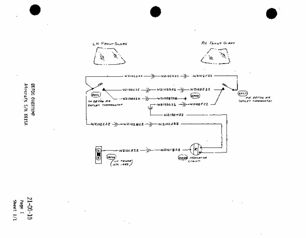
LH F~OFITGLASS RH f~ocr+ GLlssr
‘POcl´• m
j)- klZIOBDZZ 3~- W21o3 E P2
~n C´•~%o wllcunzo RI/ O~Or 1114
cc c~ LH DEFOO A14 OotLE~T
Y, 5~ 1 OvrL~r TWP~N)OSZAT ~--W2103622. --~--W21o3F22--1
Zm
i W2/cU ~22cnrv,
ZIoEC22
h W2 IDIA22 ---~---WZlol 822
~´•´•d -w,,r~
(5L~LH PRANTE/445/
1U
i
rr, O
cc O
r
Oc-´•

LH FRONTFRONT GLASSGLASS
i __I,iW2101C22 -)t- W2101 022I W21 01 G22-<t W21 01 F22-TI-
r:1~7a 1’-1l___._ls W21rJZ622->r-- W2102F22 G-- ’d
(5336‘51--- U210EE22-------/ (~Sj;7
~r77 OVER 1.EMP
SWITCH’t WZ101D22-(t W2101E22
ANNUNCIATOR
DEFOG OVER TEMP p ~-I- W2101A22
TEST
C12102A22nii
i
iW2101(;?2 iTo;iOr, ICARN0 1
(T~S).EF-12W2101H22
r~__ IW2102822 EF-13 !Z 612102C22
CENTER& AUXCONNECTION BOX
INSTRUMENT PANEL.’A"E’__ I L__.__ ___
DEFOG OVERTEMP
Afrcraft S/N 697SA 730SA 21-00-10
Page 2
Sheet 1/1

CHAPTER
ELECTRICAL
POVVER
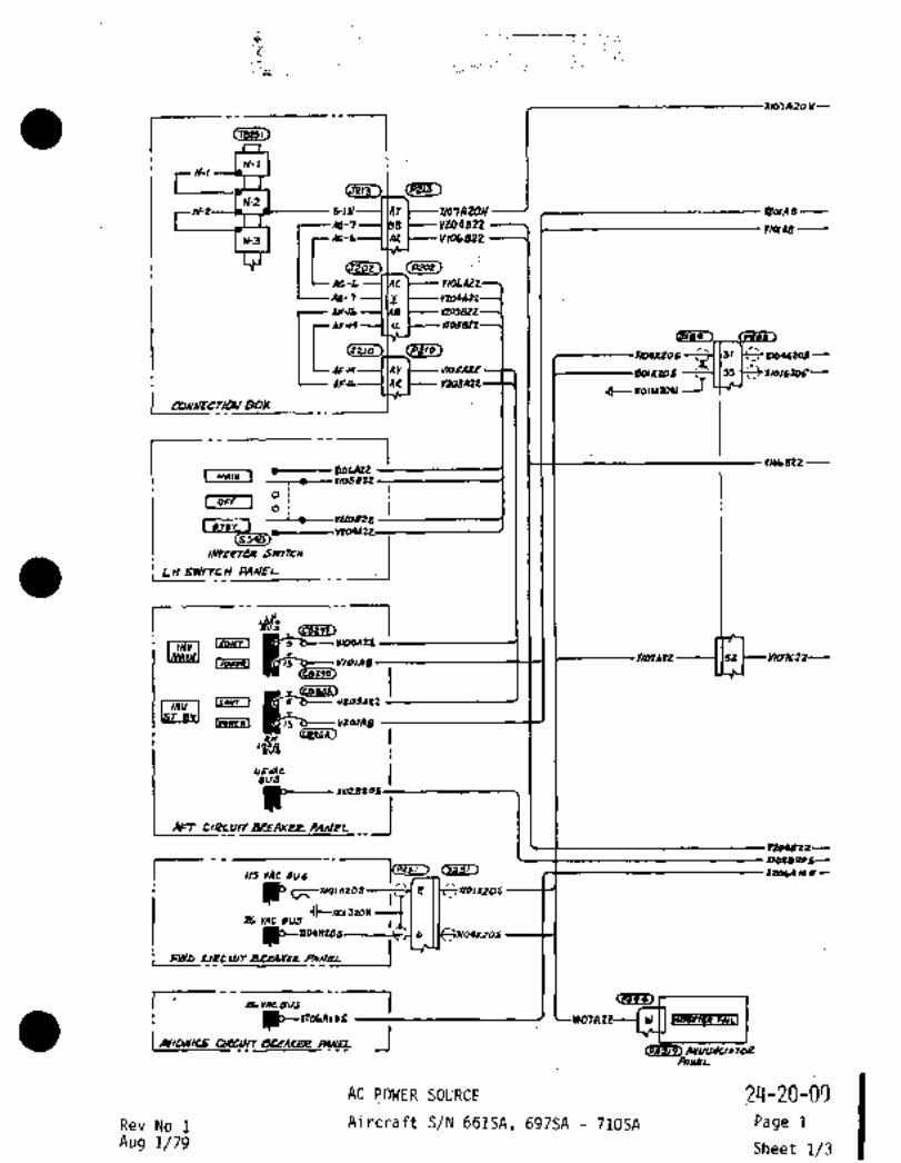
a I
i~´•....
XIO~A20)11--
I Cllsal)
N-l
I (pZ13~11-2
6-111 X167AzON----/ #olA
Ac-A6-7rWAB
AX VIObB22
Ar; -L
APJb
u YtOlA2eYLo182tY/CISgZ2 Q188~
X1WKtos-- .’191" Y164stodc
1Vrs ~WbAIZ solxaos i Irelstos--
.I)- xlol Hph)r
I-
r IYID~ BtZ
I mlw ’It------ V16&A2Z
I OFF IO
01
Y10182t
S~7LH
L~ bWITLH´•PANEII
I
1/013(2 -------I 152 )--Y107Cll----LIEIICSI Q Y/olAB
~JLr~crr I Vt~AOZ
lS .vt0UIB
w
’~JS
II~VACBUJ
P--An CIPCUrrBREAKer PAn/EL
Y204622--
Ino2deor-
113 VAC 200~3 XZobA MPI
PC~ x’0’nzos
llCXr01320W-;ia; YAc BUJ
b
Fwp r~
I A6YACBUJ --I ~erw
i U~~nobAlab: W
dePRt~e PANEL ,_Ies~
AOYEI
AC IjOWER SOURCE ,24-20-0~Rev No 1 Aircraft S/N 661SA, 697SA 710SA Page 1
Aug 1/79 1 Sheet 1/3
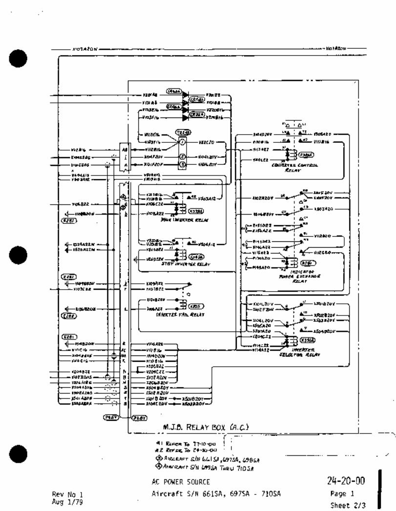
1)07A20N 1107ArON------
IR6rAe Y2DIBB
qa6~YIOIA8 Y1OIBS
YZ~BIL
tl~ ~L(
Y163NbCT824~ I Itoqelov
216 I I lb
~rr4/6 ---------I I --~--i\
XIW6201 I104UoVY1l4e2Z --laeY
IlOlceos Al 1101120Y COW~Prcn
n 1 I LJI~J I I I RtLn v
YID4AIt Y6DZAIZ
YtotAl2
D1
Y?19B16~-Yl(rBB
~Af VS03An XMPAP~VDZ’~ ~XloeFZoV
’U’~SICIC-YID6t2Z noLB20Vor hSo~AZa
~zel) III 11 I MlurlwktrenaeLa~ "f~C--E’ssoez -=-rj
i IB’ .VII2DZO
(~I?LIZtYViOlBB
vl1sa22 !41 v~Pczo
~TBT Imlolnll RELIIY
IIYDIL/ITCN:EXCHLIILVIE
iRPLAY
’1105472 ------j-Ylo7CtZ r ’1107222
210122011 --~-hX1OIL2oy
,p _t--x5o~Bto\l,I~-- I0Ob2Z1Y IWILA19 ,,~Y ~j X102F20V,,~/r
INt’rRiEl: FA(L R2UY i ~eXZ02B20VX104LZOV7
20
x5ase20vI
(rsei-)
Ilt--Y114Bi?oN----t--H 4 I t-- Y114A8
YrllP,G ----$--~AC IC---VIIIBII. IHYEI~R
x~werob ----C~-lsM I C---x~o4btov---l SPLeCr4R RCLAr
yCo C ~C--´•----t-H 1( I t-----YIIOB Ib
YZ05B22
v2we2z 11 JC~-\1204LrZBI~---XIOZAZDY
Y206A186 x20be20v
sil--wso20vrsotlz05 41C---X522B20Vpo~Atob T I 2101 8 202 --e)15011j20YIJalALo~ 911---10IM200V ’~csa3B2ov
Pf4T
M.J.B. RELAY DOX (A’.C.~4
-41 RE~ To
~Y2: R~ka:To
~AIRceAFr SIN
699SA THRLI 710 SA
AC PBWER SOURCE 24-20-00
Rev No 1 Aircraft: S/N 661SA, 697SA 7iOSA Page 1
Aug1’/79 Sheet 2/3

---l(lO~A20nl
m04~M JB
r 7YONI7DPED
BUS
_
JI Ccer?B~a,oc~ D -V’d
r 03NY14-1
MAIN
IIVYPOTER
A Ue INPUr
(Ees,, 1107A20~I L
B I OUTPJr
(r~C-- vuslzonl uasArod--F-~CI r IAc c;N~
YUPNW 11 DC QNO
XSOJAtOb 6 26VALOL)TPUT.r~------i Ilr----UUnaN I i
-Ii
STINDBYINYEPT~R
YZl2 E 12111 Y~04AIZ- A DCIUPUT
I~YII1A ILUi 1 U B IUYAC OUTRIT
(IC----Y2lbA20N C AecNo
Jt------ Y213 E12 U D PC6ND
G 26YAtOUrPUT
5
I Q-----1521AZZAI iL .---I
or-occoF1 VEPTER
Yl,aAa~ DCGAIP
nnAIL-----------dl~o) DeourPur
ua~e 16 DC IIPUT
ZLrAC IPIIT
UOSAMAI 26YlC C;llb
AppLIClerI Tg W~rH PC´•rSB/Pt-15C StPTK /IVVeRTCie;S
APPUCdOLB roL~ICk39FT ELpUIIPh~ kllTH 1AiZSO(1B) StdllC IIJ~ICTBRJ
AIRC~eAFI. 5/N 6616A, lo976A, b9B511
L99h~l T~eu 710SA
c,
AC POWER SOURCE
IAircraft S/N´•661SAi 697SA 710SA 24-20-00
Rev No 1 Page 1
Aug 1/79Sheet 3/3

IKIIA26~--
IN-l
(P2~5)N-2
6-111--1 IAr ~--´•U67AU)N Y1~A 5
AI-3AG-77----I(_Y
r~ABVIobBZ2
;4t-L
10-16 ----IIA* 1205822
AIF-IC Y1OSBtZ
I(J2~0)
11044288 31 Ylb40t0b iAF~4 Y ~OSAIP 2014202 ’2’1155 :110/6102
Yt03AZL I I
I Lf~U I r IIbo~ltos
L~ -----J
r I1106 512
L MAIK1---rt- Y109022
I OFF IO
´•i--I~----Yt01822
I Ij~gy I_
SWlrrH_._IiL)l 6W/TcH PA~EL
CcBPPI) 1Cb~trJ
I/OIAtZ ’15L C--YI07CII----Lee~sl ,5 v/oms
Ctezsr)
~1Itou~ 1 ´•~3 Vt0JAZ2
’~JB
1~ BUJ
P_,.._1roeBeOSAn rl9rulTaP~AKee PAnlEL
Y10182~--
I 1/5 YAC dua InD~ZoC--
42064 ~b-
p2Y, vAc BL)J
FW~I L~Z
C~VACSIIJ I ^"~7Ip~--ItOblllbb B~naa F*ILI
I I(YILWICS r~4) AuuuW1 Ton
AOUbL
AIRCnAFr S/N 711521 THnU 720SA 2~-20-00721M, 72ZSA
Rev No i. AC POWER SOURCE Page 2
Aug 1/79 Aircraft~S/N 711SA 722SA Sheet 1/3

1nlofAZO~ 1107~2DN---csM4Y~ldlAB Y2a1B8
Y1O1A8 YIOIB8
I XID1D~ov-I-,It2CoYI20
103F16 YWBIL
r,~ 0"
111032/6
816 I Y112t26 Y/1OBlb I~*O YIIIB)b
MltA16 8/6 I,IJdttQuM~sm
X/o4F~tov U04LZoYYrlICZt ----py9.Y
Xlo~RoY´•----KS Cb62r2Ttn L0412noL111016205 A
~Ibl reos ReLII v
ylLqAll--;H--- Y504AIZ
Y603LL2
Ds´•
’i’ D,_8C-110l02011
i P~-YSD3111L ~--XloZF;ZOYYWBZZ 0 vl66c2Z I 0"
Ilt-noes2ou -b~ Ii i Jj i Mo,al~vEnen aprar
C;-EISJDPP’--Z-~Z--ElbL~Ad2
i hBIV1)2D20
~-YLVIQAIZx~
(N4~
(XPB1
vllsntz
ST8I INLlmTEIL IIl1Ar
INDICATOCCree~ Fbwra BXcHAnIGE
L(~---- y~osln --_j& I I I RELnv
Ylo3C22 ´•----)---H r V107B22
~IOIEZOY --b~ii
XIO1L20\11 )0-x50l220VL X~6AZZ
O111020239
i I I II I INRRT~ FAIL RELAY
XI0OL20Y---\ ;~-XIOS820V20
~507ABo
11209622
IJt--W14820N 0 YNISAZt 1~119622’ ’4sr--YYIIICIG --f31AC ZZ
------$-~AM ),L--*X104bZOV--l SE1PcnXe RIIAr
YlldCII´•-------t~--IK I t---YIIOBllr.
Y204g22 ---C-H h I~-----Y204tZZ*ozszos---~--´•IB lt----X102A20Vnosnces------~ u I\-----rzobezov
sII--xswerovIsoZA2og --------t=i( aZ I C-- XSO28Z0YXSo1ALoL
,_, r r(~l- XIOI 8 202 --Q--)t501826YIUUAZ06 -----~r QI~----XIWCZDV --9--XSb3BZOY
PtB’I
M.J~B.RELAY DOX (A.C.)
JFI REF~ T~ ?n-louo1YZ ReFre To PQ~-Jooo
QAIRcaAFr S/EJ 7/15A 7ZOSA
~A,RcedFr S~N ’IZ1SA ,722SA
24-20-03Rev No 1 AC POWER SOURCE Page 2
Aug 1/79 Aircraft S/N 711SA 722SA Sheet 2/3
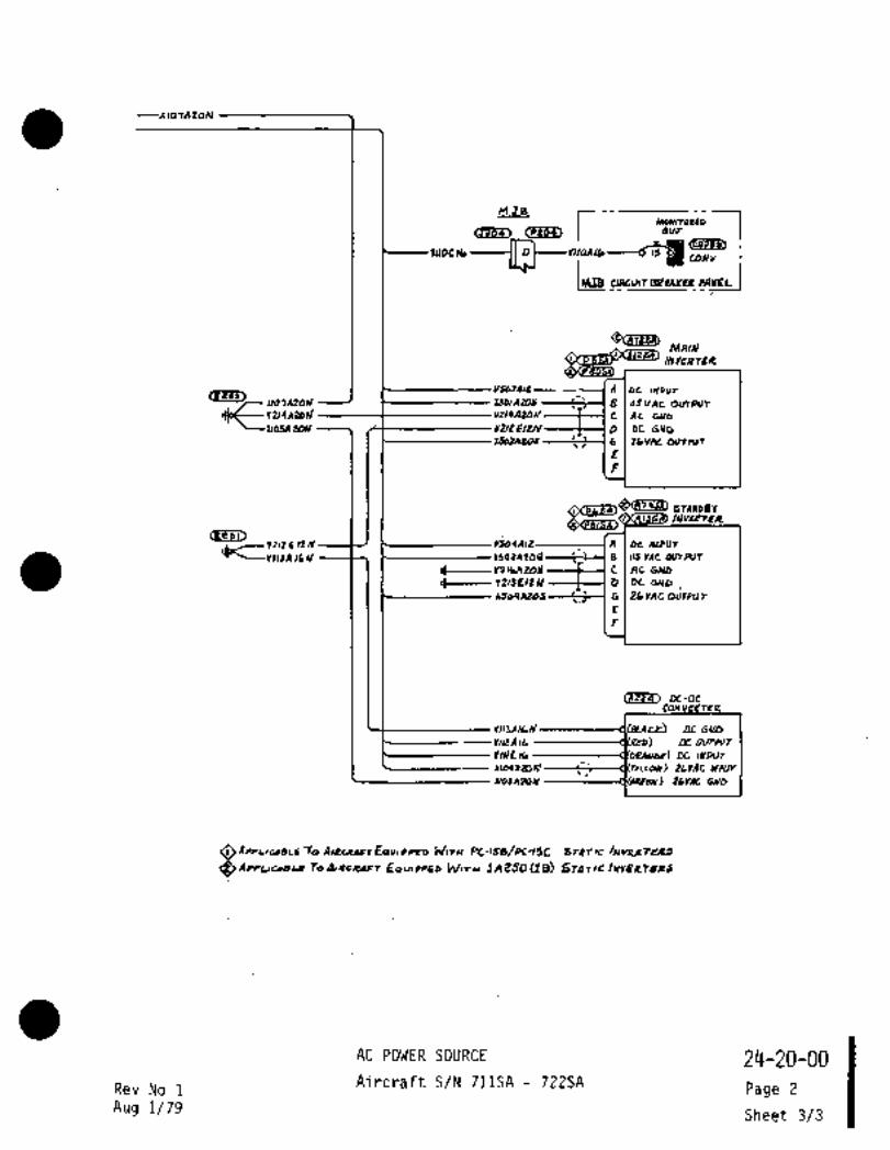
~lo,AZOIJ
JB
r 17uow~roopaBOp
II I ,I,,,~ LI~D1
YIIOCIG O d
IluJI Wco´•´•rnal
IIYY~OTER
A oc INPUT1 i
B rSvAtoorhlr
JJoC-- v’z~slad ’I; Lltl9AT6HI---1)L---( C AE WD
"-21DSA2CJN i$-----YUtN2N´•----t----I 6 DC 0110
X503A2)6 ’6 26VACO~fPOT
Q~ bnnrpgv/NVLPTPR
Cses,,Ytl2 Q 12111 YSOIAIZ: A DClhlPUT
IS~ZIIIIJA I1Al L XS02A 20~ ´•\-’BIUYACOIIIRIT
IIC---Y2lbA20)(--+---I e ~e 066
1IC---- Y2l3EIZM D I De tND
nso*Az4J G I 26vAC OjIPUr
(1~2a3 De-DcCON VEPTER
Yli3ni66’ r’lSLArr~ DCCinCo
Y,IPAIL DCDL~PUT
lIIlC Ib DC IIYPOT
~w,W8206L\ LLrAe ln~pr)r
U0SA206 1 26Ylt 066
APpLltl8Lr TQ AIIECIOFT EPIUI PPE~ WITN PC-ISB/Pt-ISC Sr4TK
APPWC~llh .Tbd,KRaFj WITU iA2SO ~B) SfPT)C
AC POWER SOURCE 2~-20-00
Rev Na 1Aircraft S/N 711SA -72ZSA
Page 2
Aug 1/79 Sheet 3/3

h:
In’-l
N-26-IIJ--l IAT ~----X/67A2CllY YZOIA s--
AG-7 V204822- 11 2/066
i[I:64-6 AY ~----1/106822
(5~202) 1 CP202)
A6-L YIOLAZO
~G-7 Y
AP-16 Mkl
U 1/05522
y104K296
AFA Y ~oSAU
INL Yt03AZe
I rcuuEcnavoox
rNUIN
I~L822
NUIN~ t---- YIDL´•WZY105822
--"-t- YIOJB2Z
V204A2Z
_.iINYC~PTLe SWITLH
L~ 6W/TcH PANEL
I 182gB~
~herm 5
CC8295)VIO~A22 1101A22yxnnl---’s Y/OIAB
Ico*r I ~65 b- YZ03AZZ
iv (8 ~---vtOlAB
i
LNSL~ACBUS
P-IloZBZOSAF7~ CIPCUIT &PEAKe;e PAn/5l _1
2204822
I2,020 ~46-
22004 las-
IL YAC BU5
P-X109WZOdFWo
F C6VACBUJ 1BNvEPren FmcLI
I avlo~csLo~f)
PA~EL24-20-00
AC POWER S~URCERev No 1 Page 3
Aircraft S/N 723SA 730SAAug 1/79 Sheet 1/3

11101A20N -----I107A20~u
no~Ae Y1D188
Ylo1AB Ylo188
la3rlb
lolP~C VasBIC
Z’a a"
Y103Nb I ~---la4b20v 2805420
~OJFlb I d-e i VIII8lb
YllrAlb YIISA22
21444208 II IVWLa~l,Yl4l22lcpr+ U
3)1 1 I 1 COU~tPrrn CwrapL
ReLav111104412 ILIL-´•IC-~-- VSDQ/IIZ2402412 -------C----~---- ~BJ1IL
DI
4’ T-
I ~42-ySa3Lln X102A20V --yT
vwsn p Y106(22"’D,
e
Eb
r~
F130~22
..II !II MIVU I
~--E(bbD22 ~--TjI~-E16LAZ2
V1l2D24d~---T--
cl~N?snzture
vllsa22
,1t-u24422 0
PnoAzaslYIaDZWoo,s~
STBYln~dnEII RUdr
P19~B)MA IYDIEATO~C
(roer~ Pbwra exc114nas8
Il~--YroqBanV i ~mvnpsAn ------~I
YI07Elt r
IIOIUOV--~L]XIOIL2L)V?. ~-IJOIB2qy
cPTuoc~onr I I
CSPB?) IN~LKTER fA)L
Xlo4120V1 ;~krSbSBtoV20
1205822L7 Wb4820y
C2ze1) 2
I))-LW14eZoN a )~----Y114A22--7 I \-C-Y114CZZYIIICIU 14422 INYEI~ER
)rl04P20V SELeCr4R RZLAr
Yl~oCIL YIIOBlb´•
Y204822----´•I--H hJC---Y20QLZ2*028208 a I a 02 A 20VJ IYtobA186 m’HI’ XtObB20V
S C- 2601 B20Y I i a
I4o2A2ob ’c~ ;ZI(---- X50es20YUwALob
’14424244 8 XIOOCe4V--tX503830YIDTAUrEO’ePUI
Pze~
M.J,B. RELBY aox cA.c.S
~I ~wR Te ’17-10-Do
2~-20-00AC POWER SOURCE
Rev No 1 Page 3Aircraft S/N 723SA 730SA
Aug 1/79 Sheet 2/3
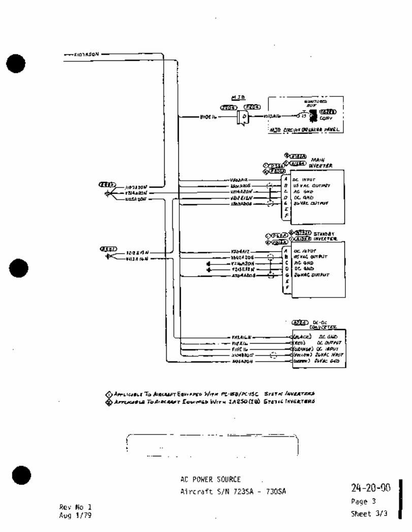
(3204~M r 17uoNITonm
dU~
n ~a ~ar,YllOelb CONY
~ulre.
MAI~LI
INYLQTER
VltptA,t ’A DL(IYPUr
ri07AZOn)I LSDIAZOS B llSvAc ODTPJT
I~C--vusnzod ul~sAzoJ ,clAe
~UPEI2N D Or CIND
tbVAco~rw+
CE~1212 5 124 YSOIAIZ A oe )AIPUT
I- L IdYAC O(rTPOT
I’’ -YtlbA2011---tl C Ae GAID
D DCbNf,
44044244 G 25YAt OUTPUj
(Ae2´•4) DL-DCCON V~PTER
Y1)3ALd DCtAlb
hlPAIL Dc ourPur
Dc MIPUT
r~WBZOS ~2irAC ~PLIT
UOSAZOW 26~e c;~Yo
OAPPL(CIBII TO AIIECI4FTEQVL PPED PC-158/PC35C S~TPTIC
CSA~PWCIIQLB TPd,~CCrt9FT WZU 1AZSD(je~ StbT~C.lelYbeTaPJ
AC POWER SOURCE
AircrBTt S/N j235A 730SA 24-20-00
Page 3Rev No 1
Aug 1/79 Sheet 3/3
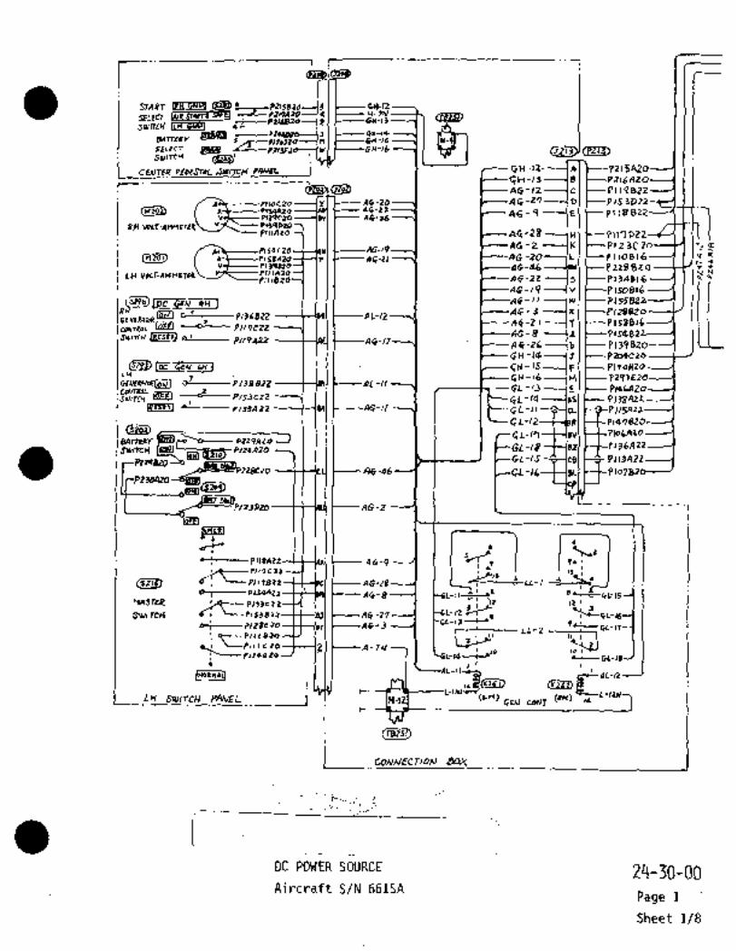
r
d(Pr~T)STAPT C~g 98-12
SELEC7H-7hl
2 3
BATTEllrt--cP GW-14
n -Is
sELEc7 O8Rn t----CH-16Sulrc~ ~2)
I CE~JTER PEb~STAL JWrrCH PANEL I GH-)2----~ A) 5620
FH-13 B P216AZO
(HzoBY AO -20 --´•J L---A6 -Z7 0 I t- p,s 3 022
AG-12 c PI 1 9 822
AG-21 4C-9 B P118822
pcclAzo AG-ZB H 9117022 17139729 A6-36VOLT-AHHCTEIP\
At soczO 19 46-2 ----(KJ ~--Plt 3020-41 I´• a!
Mzol) I--a6-3l AG -20 L pllos,bpI L~C´•-46 P 238 Bt 7
IH 1111329plN82 AC-22 151 ~--P130B16
AG-19-----(vl ~---P150816GW RH7 clf-ll 7WI r -P155822
3 A~-3 x 12882o--------PlsdS22 AL-(2
fENEW)ToR 3 66-2 I --~r ~--PLS8B16C~NneOL IPEU -´•-O-- PII7C22SIVlrCH JRESETJ L~1
P~9AP2AG-8 ,rl 1 P154822
66-/2 66-26 b P139
~H-IQ´•-----(;T I(s~qi)loc GC~N WI CN -15---(F( C-Pll9HZo
IH3 66 16 ---IH I P29)E26
~-----P139B2Z AL-II3 GL-13 5 P146/iZo
---0--P/23C22 GL-14 P138A22’L~---P/5SAP2 66-11 ~-P11Snrt
GL-12 P14782
CL-17 ’svl~-t-PlodAzoEVlmrrr P229A20
Slultc~ -18 f-lerl tt-p rssA22
L-/5 P113A22
34*VO--6~PnBCm A6 -46 GGL-IL--$--lgLJ ~-Plo?82
LLPI23PZOI-tt-IRUI ~--AG-2
-sc" R~~-t"t--~---- P11BAIZ a 6-9 I
d: L-pllle22-CCI~CI I ctG-ZIc~----plldC22 0
I~ PIJQnZ;1 46-8 BLt~--CL-I5rriSrrR ~-P1)3C12
-lz~a ,Z I
SwI TC~ 6; A6 -27 9 i~e GL-Y
97-- Pl~Oc 30-13- 91 1A6-3
LL-Z M-17Pcle sw
L-IUli-´•’"i--Pll+a 19 tLi
I~oannll -1~LN SUllfCH PANEL~_ (LH) ~H) L
Fw CONT 19
L’1BOY
C~Zii3i)
jDC POWER SOURCE 24-30-00Aircraft S/N 661SA
Page 1
Sheet 1/8
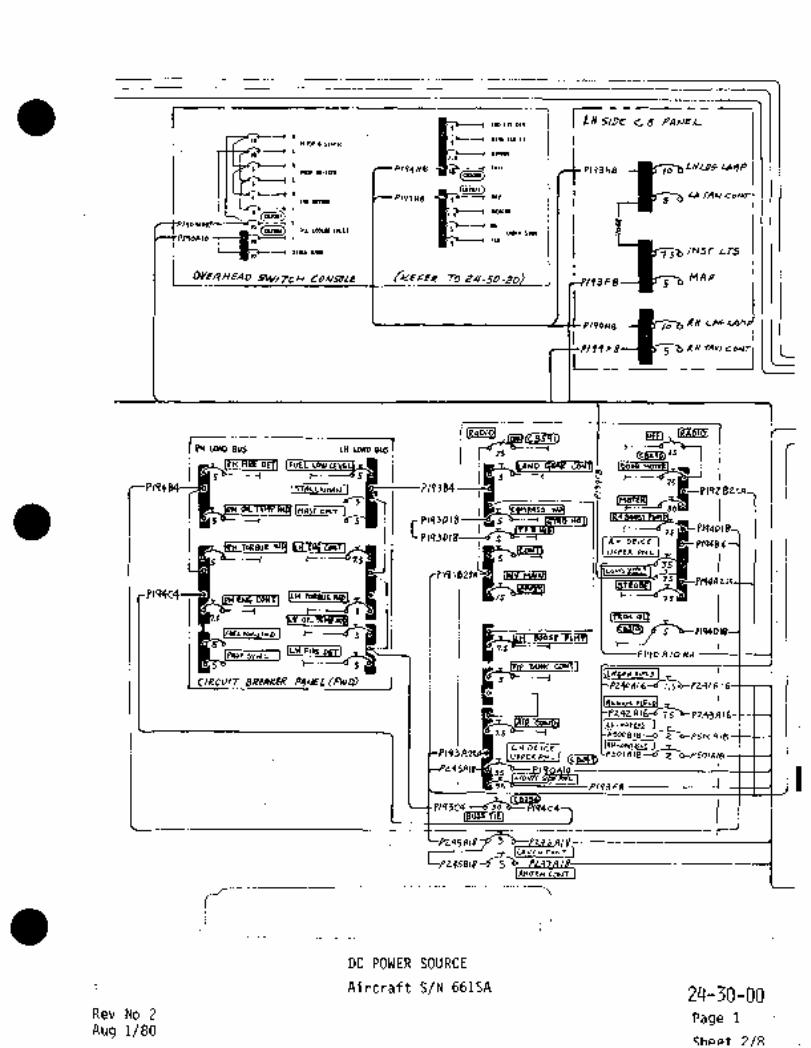
cs2oao
I LltsiDE Cb PA~eL-In In PI*
10 YI*C ICI LT,Imr 1 rarre I:
to sraar
IIOI I-lc~lP199H8 III P~93He lo
(C~1080)
I(cam~s)
s
t
015 mllI P193HB uvr 5
i_(MMB~)~LCOI
M1U1I ´•I
ZO~(CIMB6) IO
UBIISIMi
CIMB6 OIL LmR I*L~T I
tom rsa
SluL rut 7.5 /NST~TS
OYE~NEAO SW/rcHI MAp193Fg 5
P194HBdC7~aA4._,1
194F" I~5a IPHTnr( CDLITric~rlI
o Ist~J
laH U14D BVS LH LOAD 815 25 1laH 088 p~T1 IFVEL LOW ILAND Gt4R ~"nd,
s ´•1 5 S I t~’
19984 I PIP~ t L~--P192 Bz.
i ~"9’"’" s~s p_--~ 65
ISP194D1BI-´•´•
019381 Z 411 DelcE I p194B4IVPPER PNLI
75 535
null ry\i~
p194C41
\LH mP8UL 113pl
5 i 15 I I 25
_Jr
5
I ILH FIOEDFTI 7.5190 8 to 811
I 3 hP ~WIK GlilT~
1 ClRCU/T BREAK64 PA~EL CCWD) I 5 P-..--~ JLH6EIICIELD6Ell CIELD
IRW6-~ F\ELDI1
LLPLORDBUS 1~I_5oog18--o 2 ~PSooA1B
i...
I LH DEICE I LIIT~oADqv3 1~3 501818---0 2 bP501818
45A1835
Jyar35 ---Pl93F8
P1Q3C418uu Tiy
P245Rlg-P 5
RHGEN COF)T
i- 1
DC POWER SOURCE
Aircraft S/N S61SA 24-30-00Rev’ No 2 Page 1Aug 1/80
~hppt 3/8

-3
rl
~za;ii,
ec~----pzAO
e P4AO N
CdC-A 4-- ----PIOA16---- X P1o5c16 ti3- l1ose16
--prlAI6---´• 1 P,1~9u P 112822X X--PI~A16--´•´•-----re( ~-Pltfc,6 PI1Pe~
STAR rES
GENEI~IOR 6
L~ ~1W(ilJE WACEL~E
SUi 24kl
(P~E, ceru-,I CPliri)
P148A22 5 813832281’14422 P1QPBZZ~3 .IL DC~ C~EI)DUTJ P1~1612-7 P193AZSbe~CP- P191AesA
.L~ )N~----. l22l-Pl21B22P19182SA
P164e 14 R60816PIPZB2Sn 8bIhl~oaraa4a319
X XP/Qjg/b P~SA,C,
-~--t 3,22 222
~i?lPL)
E 4C~-- P4/76hl I LH W~EG
cc)-- P3Aa ~fbiD
..,PIOA16 L~
X P13ZA22 P/S2BILob------ PrIA16
-~--PIZA16 -f--(e( ~--plboDs6
PZAO --7 IC
G(E41CRATOR
LH EFJG(NE NAC~LLE
P14/AO
DC POWER SOURCE 24-30-00Aircraft SJN 661SA
Page 1
Sheet 3/8

d/61BO
PICI 80PL1DA/6 Pn~DZa PlolD PL92Alb
Apr(9AZO Cwo
fW LH aFVtPCE i PHRVBPSECEIJ
P149C\ZO--dSII COnaUJf cuwr CVR4ENT CUf- Slrt PntSAa45LAY aoT RELAY
l~b PII~AfOi CrZ3~ ~lorlroPILlci2 i(i
Pf:Ir--P1(9I I~ SHVhJT j PW SW(lrJT
d i IICt---PZ’~AE4~.AIL(IIE (a~)i P22rBZa P159 P~35A20
P2214Za 4Eu)rPIPPCtO
i" P129A2O --9~ 23 n ;Crp FalcuqEPI%Jgf0~A~ 1BL19~
PI~IBo In,g ’__
It,
A
P141A2SA-~-roL2FAsA
r~OPmi RnLRr 8 1
,EMIOR TP_S"O RE~AY(
p163Bbas C~-
fP-ii~-P/B’A"UP,BSA,~
316510 211618
c-´•---K137~01..
21-1 QWEq4r0Pprr24ia
P2,bC~o P/~A30 RCLATX) L
pl4qEZO PZSER,ZS
Cr~)P113ruo~ as
P~15r20 ----~J PH SI~PTER (LbA12 Tf~B1PEL4Y P/2SIIV2
9SY~ P~IIOA(a*’PL- P~r(llP
p17ar~a
Plg3AM tiZ sI’#Uo~avrmprD B~s 33CoPrr40L ~LOY JWES PAVILCfL
ajry ~EIAr
DC POWER SOURCE
Aircraft S/N 661SA 24-30-00
Page 1
Sheet 4/8

d
a´•
P1O9AZO _~F1D
PljlSAIO.;I Pl
B
1 I I rt--tf~- P22Wo-/~QP
C~roQ) nJB
(r~ib P16 ICU
P2,3EZO--~ IS
rUo
~f,
IkY P199Clo
cia IO(
PU~PIIO ~lldAio
~b ~aa/a P´•1+C166/6 r/CIC16
Sodl6 pl2olt6812P, p(J-Sc~2
I p/´•cnlo PIL6c2oP17949/6 ~-P179C16
CZ2
pl?OHZ P170N PIOBIZ PI
PIS68~ p~56*p/1542~ C~L PI)SAII
~VdU per ~1 couil
(ca29dP ~+7 [LD1~p,*2Ela P~SF16
160616 ~iL ~16oC/6P119BzZ jy P11Qc2lPloCnzo~ ROoAt
/76a16 P,76C,b
p136~1L P1)6c12 LPIXS ’7319316118C~2
PIILrUlu--t-1 I~ ~P,IICZZ P/S)C~22
r P,309~o
IJC~Z FZZ
PllIBzl ;3~3
P/oSF~
CU) P/I?C2I
MJB CIRCVI7 BREAICP PAI(ELPI~POlb V1 P13Q~Y6J961a--~Iwwo----l lac(C P/wcn,IS3~12--j IH P,39E1Z
P117~1--I IL F--PI13rll
DC POWER SOURCE
Aircraft S/N 661SA 24-30-00
Page 1
Sheet 5/8

1~7313) ~llbC
~1PI44lla
aPlacR p,,qCn
212 o16 P176CLb77 PII’IFR
P117C 2;
RUPr
P:(B622
Plm~ZO
Rn OVEP
i P)4,DZO
PIS7~20
P~,2DR113Cnlscn
~c,BU,
I 1 11111’"~’" rTI I I JJ~PIDU,6
PCYU16
d1 Z I lr;6; a~buLaT0R
1P170NtD
PLO)AIOPI 701 ZO ------~n,l 620
70EZO--~; i I~L-PI?OAZOOP1IBE 20 C’ "~----.P13PE
q-~---P 1l9E20
143820 P103B2O
1 j
3616 U PIO1AICPL4)A16 P193R16
U
1145116 P105F1601360213 P1bOE i) ~---3P*l a Pl/sel6P1,9E P160L116 Q---~ 1129616
Q~ia13sucRtup164LZO~I
P11S8,6--9 e- P1’7tt)6
~rlc5o16d 6_ ,lpst a
Q 661SA, 697SA 700SA
O 701SR 713SA
DC POWER SOURCE24-~0-00
Air´•raft S/N 661SAPage 1
jSheet 6/8
a.

IIt
I
EN& START RELAr
QZD
P13ltZD-~ InC p1,1020----1 I 1. I 20----CI´•~PZoQ( ZO PZ C 01700 20
lr~91?snzo ~L) I I P178A20 IJ.P1868ZO --I I1II l---PIILA tO----J*´•
oeD PLZ6I120 ----1 /--PI G-’P 177A20-J S´•
E17e +L--T~ pL24C1ZD 1 P I J9FLO~ I C---Plf6AZO----C6´•
1225 ´•w
j~----p 140FLO--~VOLTAM SENS[Ntl~ii%d´•xl
´•2 ,-~p
UtaJe ´•~F--- 01050 10
´•Y ’P170AZOPtOQBZb--$-eM I I F--PI?OCZO--YTF--PI’IOF20
a~---’stboA I?POZO P1788
P170AU) .01780´•*I´• I
~-’p173B10---- IbZAZO PlltSZOEXT POWER ILINT. REI.AY.
197820
C’ 177420
c~-pi7sAzo--+-M I I I I ~--P1)6bZO’´•1
´•u I I I 1 71 P’s60 PIO(L 20
’PI(OBZO’i’U ´•Ptd~llZO
I
´•o I
´•ah~o.=i----PLoonto
SIBRT SELECT RELAY (RH)
QZ~ ~I1I-1 P1?8C
´•a
1776tP T.. BPUISLBESIJULB14082 17dBZB-----~L-7~t----pza,Azo---C/ I I I i I I--’PIICIZO----J
1~----P203820to
I ~-iP113810-i7TJ-i ifiiI~
START SELfUT RELAY (LH)P139620
MLTACE SENSINGP1~4A20
P170 F ZO
:P184s20 ---a´•TJ-4
:P1OZsZ0 ----aTJ-S ´•~e,
20 ´•e~
nTB RRA’I BOX ~C) --c-PZLZBt~--Q ~tlD
RH GENnt4A2o --C7 2 221
VoLT~ E.PZUIP6 P2UB20-Il 4
U/2222 78ST
PrzsAzo----~7- 3223
r ~NnPOWFR EXTHANM RELAYLzo p!lole
QTi?iD i. .P19SAZO renan
I----~~a RFIAY P,OX Vltl
OC POWER SOURCE 24-30-00
Aircraft S/N 661SA Page 1
Sheet 7/8

p117ba ---´•12~----p127no
---r:=rI´•AI~----P!21 r Ib
,~--Pllrna
ri\L PIZZB:~at RI,T;FF Y Pfi.ilr p Is 7~2e
hiCLILL: L;Lb----pl2~B
IP191428
rl,la’zo1 I 1 i 1 8;7 -ij
I IIJ’IAZ(I~1
~GLfZD;r
so ’-l~---pltsna I~--PlbtAo
j r? i-camncP;llf,
P1(1~0 ~1L ’PI))AO
’aK139
t 1 i I IA2O
:P 164320 p
P1?1)C 20 r0
P113C Ef-------Pllt~ZO
Im=´•ct~-- Jin 2 a
P122C tO
I r´•s~ps, :P126AOH
PIILAO
:P~ZIA20 s &ZZTER(WalXELEC~IIIU1L CbnE)
:PIIJAO
’Pr6 2110
IDI1P1
"~----------7 1 III i I
I I 1 111 1 i. .Plj3AOn
Y----PIZZCZO P132AO
i/.P122E 2D
1 I
´•P128A 20
i AFT.F1~CTRLWIL LOPIP. BFLAY PPMLILH)
:i DC POWER SOURCE24-30-00
Aircraft S/N 661SA.Page 1
Sheet 8/8

IGH-I2
I i
START f6 ~D
SELEcr 1418 nAaTERFEI pf 17 6 N-7N-4! 021 2 &H-13
3\91701-1 I~W4Fml
t3 GH-~
BATtEI~ mRiESI 3
SCL~CT n c;H-’s llN-4
swlTcet 189941 611-(6Ts2an
-----L’ I ~I <prru
GH- 12
(M2O2) d~ Pllac2O 46-20GH-13--l8l ~---P2I
P134AZd AG-TZRH WLT-AnME J8cN) AG-1t ,c( I P1198ZZ
sQclo 46-26 AG-Z7 P153bZZV- pll)moPIIIATO AG-9 --IE I ~---P11882z
1 ,IWJ t´•---A(i-19(n~OI) plss4~0 40-31 AG-78 P11?DZZ
P/J9D2a m
L~e \IOF~-AMETtft OAJ-8 AG-2 K PltSC2OAG-lo L 9
p,,,
NO AG-46 P228BZO hF--P113Ba ~Ki-38
itAG-ZZ ----(s I 8134816IDC 6eU aHl13m
rYb p A6-37 AG-19 v PISO8lb
1~-L----p125Rzz P/558~(4292) A6-36 PlzBszoNo x
RH 684684248 Ab3bA(i-ZI----IYI
CQIITa915Ylnc~e AG-8 ,PI ~--P/J48ZZNo, 1 ~6-26 2238820
PI(QA22 AG-I2 p1398SO
Wcii, GH-14 PZoCCIOso~ GH-15 F ZO"’ije Gw-/6 IH( Pz1JEtowoI
~C-IJBF i LA 16-(2 1 G----AG-39--~11 t P146420rot ,x-AG-41 P138ATZ
LIFO p138122 42 P115422.~----PlzYltz-y I I I I 1 AG-40 147820
LH wo~ P1~6 46-39PlotAZO
JVIITCY"~)---P147ALOI I~Y I ACiP13iAZZ
ACi-38-0--ksi
A6-,l AG-36---~BL( ~tP/07820’Ic~yYO1
uc~LAJ-~0---1691 tQPZ’jSBZO~B ~-PZZ9AZO
k"~----P118A22 fttt4XI t----.AG-9~t-- P 117C2201 ~--PI11BT? aG-28-1 Pls4APztftJgn( AG-8
6;Y~- P1S3fZZp1S3 AG-27
-1 P128CZO t~t(8fl ~--AB-3PIIIBlo
PlllcZot--fl%l A-7~J
PlzqA2a
P228CZO
_
P23a92o
lgqT Jon Cszo8
,042o~---plZJD20 AC,
I~D
LH SWITCH PAhlEL BOX
661SA, 697SA 700SA
O 701SA -713SA
DC POWER SOURCE
Aircraft S/N 697SA 713SA 24-30-00
IPage 2
Sheet 1/8

IP~;b´•?. YI*CltL1T11~1 1 I LA s~F CB PA~Pc,
Imrr
not a-lulPloqHa P193HB lo LNLOeC I~nP
(CIIIUIO)
P193H8 Uv 1 5rr ,nur
i~ij:luca I /hlST 175
tnlosl
tO
~IO(L(mZLIIL(T Wllllb*ClmR6
10 re
n~*ur
143FS
jP194HB
I: 1
I
RN lalP19~FB
iIlnADral75 [C~34i) eF1-´•~ I1I~HIPL\D BUS LX L~AD BU5 I
IFUEL Low 15---a sM I ...1 9 t´•´•
Is
19484 P19389 192 Bz-sn
b~jl~ef5------, s
~PiP)D18 I ’-"^’C~k"s a
IR~I roRBo~-iimJ-´•---1
IrlUPPCR P~´•ILI
35 1
pw 41LTEL~PIYM
djPH roe411IUI)] -?f$Y
6. b-´•--~ S
~m I6~-bPIWPIFUELR6~JINDI
5 7.5190 file 811
1 CIRCUI7 BREAKE17 PA~E
"113 ~P,
ILBloRDI)US I_j~lonDl)uS
7.5 2 bP5ooA
8193 501818--0 2
LIS*TS
35~---Plq3F8
lf3C4
P2YSR18-P 5
45818RP ca~J Cc~JT
DC POWER SOURCE
Aircraft S/N 6975A 713SA 24-30-~0
Page 2
sheet 2/8i-:

,i04~ LY
!4 (Z~i)
8 PZAO
--Y5[AZO--´•-(E PQAO~J
C4-----P3AO ------j
---PlaA16--X PIOSCIC P1OSe16
--PrlA16--´•´• PI(ZAZZ p 112812~I X X--PIZA16-- e P129C16 P13PB16
STARTE4CENERA~
i L~ I
STA 8430Wr,O
I~R
PIC~8AtZ I Plf8822P194RZZ 111 P1Q982Z(i~TiS)
^-j .IL ~C (IU( OUTp16182tPlq3AE:llek--P- PI’IIAPSA
P19184s~i P/zlArt--~
P1944Wl~tp-PI 924 P~ocl6 P/608/6P19282sn----J X X
P~4?iA,6FI~D 41lL~IDE Pk~,CI.)
(~7Cb 7/h p22
r~i491)
K~ilA70--´•---e
e pqAo ~J1 LH WING D/SC
Cc(-- P3AO a~7) 1
A~-- PIaA 16 H PIA~SEIL
o b- X Xi P/s2A22 P/S2dV~
----Piznl6 e P/60t~6 slPZAO --7 1 IG
II GENCLUlmR
I LH r4 19~b i
P/4/AOP/slBo
DC POWER SOURCE2rl-30-00
Aircraft S/N 697SA 713SAPage 2
r-i
Sheet 3/8
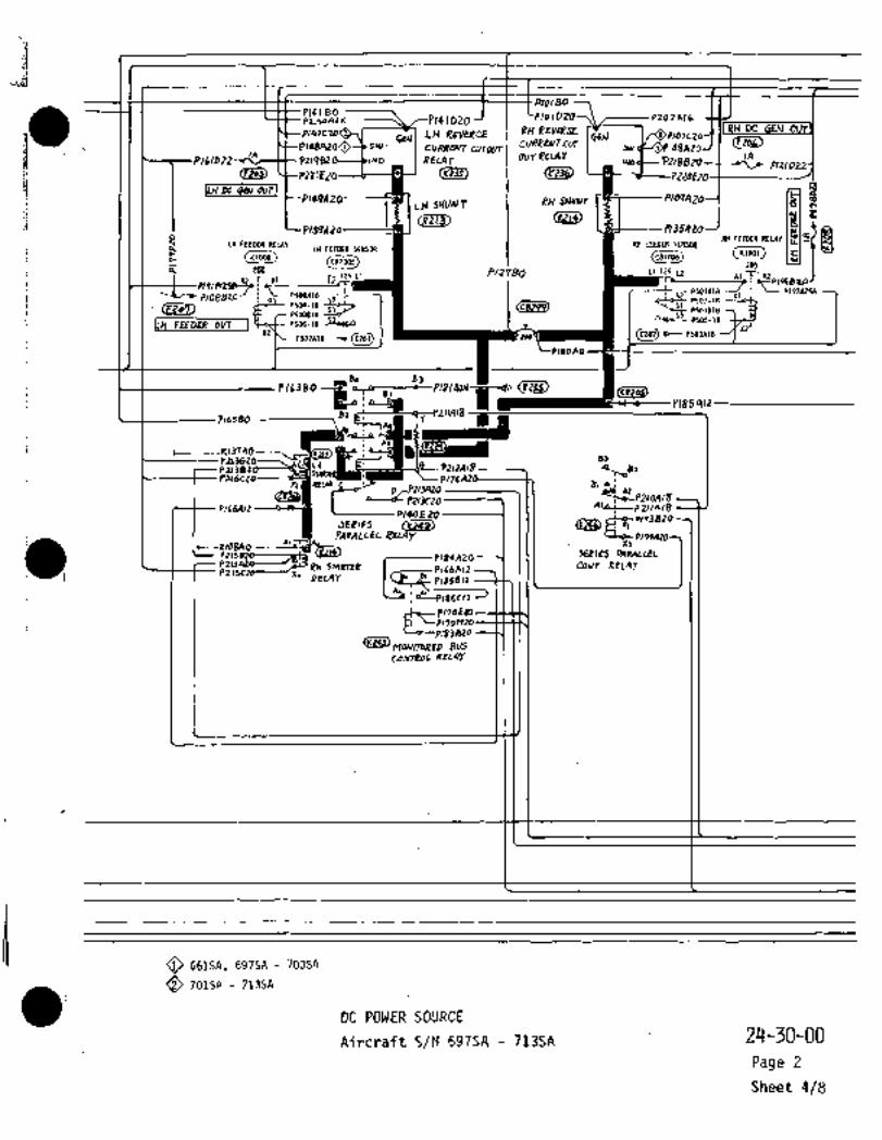
IP/d~Bo
P(Z´•l 80 PlolD207\Pr4oAl 6 IDZO
SEJ LH REVERCE RH RLV~PSE 811 DCGEIJ P/07C20
SW. C0~4RWTCoT- SwcvRRu~ t(lTWTI I PZIP8Z(~ND REUIT UOTRELAT I
CEZ~ CCP221E20 L -~U (y~jg) I:LH 90 8811 00rJ
LH SHUNT RH ~ICRZIU ´•WL4) P/35AZaJ a:
:I PIJPAZ
i. KIWO
RH FEEDER RELAY Ju~LH FEEDER REU\Y IU(.EEUIER SEH~L1B
LH FEEDER SEWSOR
(CBIM)6) K1001
200200 P/2?BO 11125 y dl IVYT 51 i1’25 L1
i ~25R;pi$ P5WAIBI PSOIAIS
I Pl~BB20 5:52 st~- Psol-1e
Vza7) P5W-18 ?To-tP a~L P501B18
´•Iws-s ~P Si~i´•IBP5WB18 -"a sa
.i52
P502A18 -9(0251)O- P603A18
X2~
48
C’ZZJ’
P/85A12---------------Br 211418
P165BO ´•I
P1III)IBPzl Q~oB2suly
P16(AIZp140EZO 3820
PAWILLELSE8IES
Al 55~´•--X168AO -o
p18*AZO F#8qLrEL
pH SIA~SER p166AIZ COhlJ RELArP215Cn~----/X+
qELAY
85012
p170t! ’p170M
~42)MoAIIToRED 8V5
co~NraoL RU4r
O 661SA, 697SA 700SA
O 701SA: 7ljSA
DC POWER SOURCE
Aircraft S/N 697SA 713SA 24-30-00
Page 2
Sheet 4/8
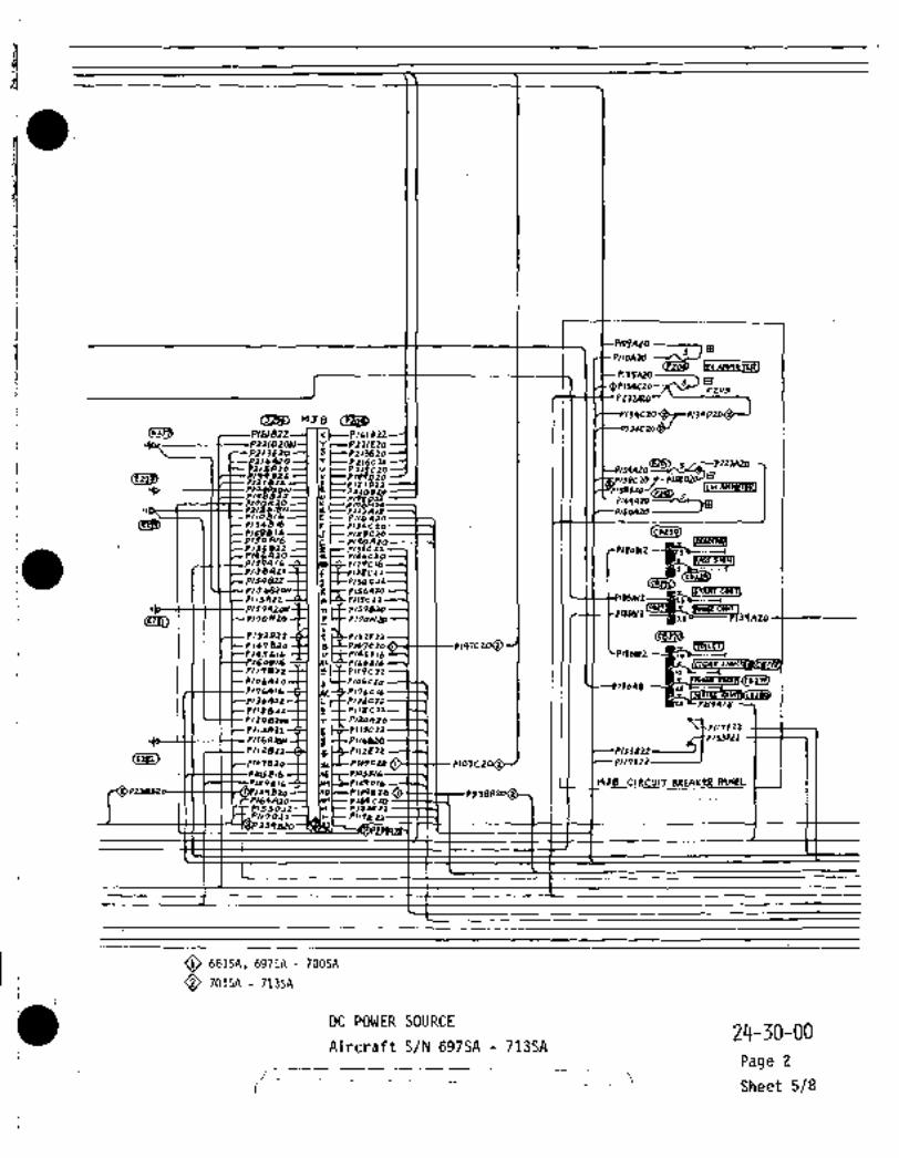
ti 1 I 1 I r--P~OPA20
f;I 8135529
8FZo3
PZ
i~s, nJB
P161822 8 Plbl PLZ
:j,Is,,
o 82160 105420 P11Sclo
V 1-8109220 24e,2lor2 ILCI AK~RI
,ogl 8110430(r~W 2134816 P~J*C10
1588/6 plZ%C2Opl3o 8/6 7, ~u
~mR61
P/74~,/ 3--1 bB1 C~ i,79c16P/S8L12r-U2154822 /sqc33PIJ p~S1Au,PI,SAlr 81/2931
In~Fllsleloplssrvr
1 crrsi~ P110~0 r P170h12~
Ii I~P)61F21P 147 Bzo y I+pn7e to ~iaiimP145B,6 0 PldZF16 Pl%agR 16/60314 ~-I ll)LI~--P160S/6
8113822-6-1 I-r I-F-PI,Pcll064 i 1Q6C30 I I I I I U
p176AIb P176c1636412-4-1 ii I-CP136Clt 82124/8
8118822 pllB
812082911 r~P120q30
(C282) plo7B2O--l~ I I I
pl~snlz 13E22PIUFZ~
P1l2822 r~PIIZEZZ
1115216lt9816~ 216 nJBclRculT 8REAYER PANE_t)38101 158)-81395100
164C208153231? IW91122221 nle P11I8Z3z3q
O 661SA, 697SA 700SA
Q 701SA 713SA
DC POWER SOURCE2~-j0-00
Aircraft S/N 697SA 713SAPage 2
sheet 5/8

B~iLt
pl*ula a~Plac~ IsLR-t
ilI--P: IsC
2~P117tnmm
C1621 F´•nbZ~
:~q
Pl~on,o
Ruay a~LAY
.j~e; ~u_
0141020 ----~el i
PIR~27 I I ID~- Pc ~iDRp1lsCn IJtR
ii I~ IUGtCplS~sa, M;I I I (/I LP11~820’I I -I I I rl
11 yLICTr~9(lf Pr Y~L ;r~Yli
PIMA’6
N
P1(9A16 1)9*4
aEbuwToi~ "wI lr
p,4e42o(ih r 1 14-
i ~´•+------P’1ON
61R20pll I (YP4~-P230AZo
r170FIO------t~,, *~----P170 620’10120--/: ~---II?OAZB
OPIXBE n~L---´•plJ4_E L
czo~ t~
.,,´•i~-- P 13911;"-1I3’IE20
ldJ820 PIOJB2
I I I I I P243R16
3616 11 U
´•II
PIOSFI(
Fpi#FzoP1~9 E ’P160 A 16 -~4-r P:29A 16I ~LH) (Rtl)
p164C~O c.."-~P-i3 E~sij´•´•1134EZO
11
11’!9A16 P17St)16-1 f- PI’IGtlr.
bulorolap170~a´•I~D>16 p~OSL*
p~S416 oloss~c,
O 661SA, 697SA 700SA
O 701SA 713SA
Dc POblER SOURCE :2rl-30-00
_
Aircraft S/N 697SA 713SAPage 2
:i i r?

r---------
I´•~Nli JTART CMYT_RELA’I
P(~10 P~03 20 I~IJicrO nPlOdCZO E
i"i~ C-~2;-P226n ~PI’IBA10
/---Pld6 E !nle plB~OZO PIBIArO~D P!LbALD ~cP1346 .P177ALO S´•
/---R zqe plrqnro P1~6AZO 6´•
E278 ’W--ILLS rtrsar PIQOA
WYO
~---I I,--´•Prl,ozo----´• plojc20 Plt,o 20
L.p I r)B 20
41 ~P170A20
1 ’1104 B ’P170C ZO :Pi?gF2a:P1799ZO PI1RB
´•~I´•~cllt_´•rl71Aid-, PI?IAIl) 1780
JB ’P(b2A ZO P18LB2JB~o
rt~--Pl)lt, 147820
C P1’17A20.P17SA PIBd A P186820
’´•I
´•u P186D I11L 20
’PI(OOZd
6263420I
´•u 1/-1140tZO
frUL--p/OObZO ’UP~O,f´•---PZconto
.1
´•(lli~
81780202
--´•I
´•II
´•a t~LZ)177~ZPdeJUSLB~LIlL]B14602 176820----;c~c--7
I‘ulo6e~o-------------,
’YIL-P103820
"1AZa
Y
to--I7rJ-l ´•ci~LL=---‘PZOI II 20´•r
JTART SE1ECT RELAY IW re-~---1 39620--~3´•N-L .(LldL)C P184A20
U~L----( FZO TJ-~ -yZg~ UbllLZESI~W(.
0 ---~´•T1-d ´•C~5)
PIBZ~ZO ----C7TJ-S ´•~p)
20 --I7´•r~?---c-,2rrgto --~I11] TZLD
RH GENnLqA~ ---~I, ri?ZI
YoLT~ E:IW1180 ----L-pW BZa ----f7 4 r ZnL T~ST 1LH
~TPSALo--I7- .223
i Vlru
Z 0I Ilj---- 8!70 K 2
L´• ’lr
IUBIVBLBa~LIUi-I~tdB RFIAT enx
IDC POWER SOURCE 24-30-00
Aircraft S/N 697SA- 7135A Page 2
Sheet 7/8´•

i
JlhlLTL~,
I:;
ii´• F127~0
(THD--r /IPIIIAO
Plz’lno ---i: I~f-P!IIFlbIL’ PI1~B!
ha~ a~TiF’ uO)17R!
´•CliL) C;d---pltJB
IIT’AI
iEXT.ehjFR-EEIA.~i
II /--’p!j,Rzo
a;
´•Q;D
’I a~Di ’p16lna
c~----.rlsler~
~ZDi. I I I I I I ´•r~
.:j I I _
P16)AO
i~)IJOA23
BLb ´•cLl~i,PlkbtO rlb?A
P13)C 20 to
´•~P---PIJ1BIDn ----rSr--TI)’IAZb
PI21C ’P12JBtO :P~2t t 20:P121C 20--cJ
:P229120 r:P)Z1A~AdH
P12tA20
LIT*T
IZ Pl2
‘216 ZAO
i :PI(JAO
´•y
:PI)JAQN*I
~----’rlZtCZO ~C(JJ I i i ’PI~LAO
´•FI~1ER6UICI REV\Y IL-.PIIIE2O ii I -I I
a~II4)E _,,,,, to1 I
L~ ~W7
1 i´•~FT FI~CTRICAI. L611P. RELAY 4P~Fr. dll,
DC POWER SOURCE24-30-00
.i Airc\-aft S/N 697.SA 713SAPage 2
I-I---
Sheet 8/8
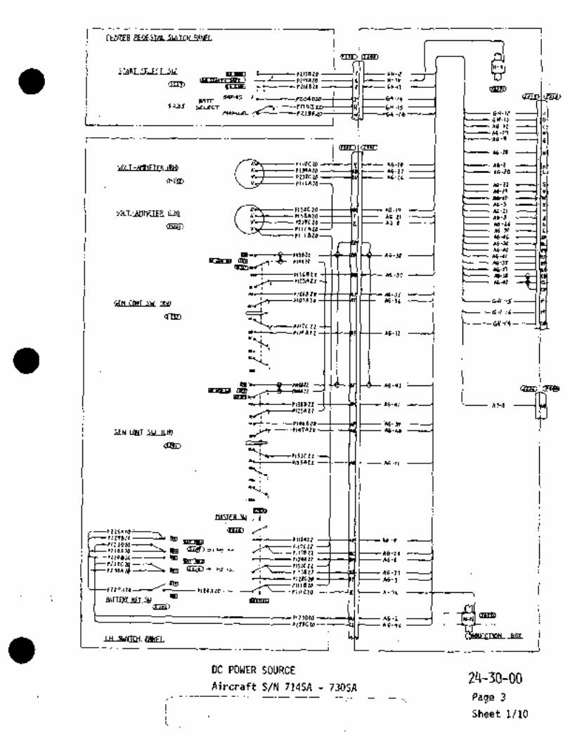
1I
t--;---rtrseto ------(f(.C---.GH-lt11-211
ns~cHm ~------P1I(BZO ----T--1ZI~---.6H-IJ ----1 1 ´•~fD449,45 p2040ZI, 6Y-,t 1 I ’c~iU1 C~Lnl
BRTTh135 ~-----pnoS to---t---(HI ~----Gtr, -15
-P113F -Ib bH-IIV
-46-12 1
514-13 11
18-27 -------(´•la
1 ma~I~46-4 ---(.IE
~116-21 11
IOCZO r As-to 46-21134421 ’A6-22
’1Z31C2O A6-Z6~eL) 1lllAZ07 I I I Ec--- 16-21 I´•IS
~A6-r0’*Q-)r
P1SOdZO A6-19 ’A6-ZIP)58A207 ’1 A6-21 A6-8:1ZjPC2O A3-8 .46-26 b(nzr?u ’pl IlAzo III I E----- ’A6-R 1.1~PI, I B207 I I E---- ´•~6-46
46-34
~AO-4022 --Ca----lll-~-- 46-38 .Ab-41
~Qe mm 46-53´•~-n
lkt---~P136122 -Ht-dd-~-t-- A6-37
Ir~i_-Plt5A tZ 46-42
#-Js
´•Kjls----Plo7Azb P---GH-~
O~oC~ Grl-~
r~---P117C22--M II~--+------pllQ AZZ ttS---kE(´• ~--’A6- 12
"t~,10´•
h--i-----PIJdBit tt--~BH; A6-QI L-
~giaamo46-42 i
~-----P1ZSn zt
46-39
´•~W;ebLWbllL´•M A6-40
~S----PISJC 22.*LC----~PKSAZZ
-~IElo´•MSIER SU 1
tZSAZO‘ ~i´°plzpszo ----~s IPID ~I----P))IAZZ 46-9
p23oA20---anm ´•Q~D lplJh--’lIILCZL
61 ~----P11782t 28’PL ZQB 24 ~A6´•6
3on2)------2, ´•gn~tL
61 46- 27plzocza 46-3
ZPnZ~ P124AIaa
:AATTEEL~ K~r SC/ -IgOi~IlBIJ
P2Z8tZO ---;---(CL(´•f---- ;46-QI t--
PIZ3DZO ~6-2
wswrrctl e~vuEL
DC POWER SOURCE24-30-00
Aircraft S/N 714SA 730SAPage 3
j Sheet 1/~10
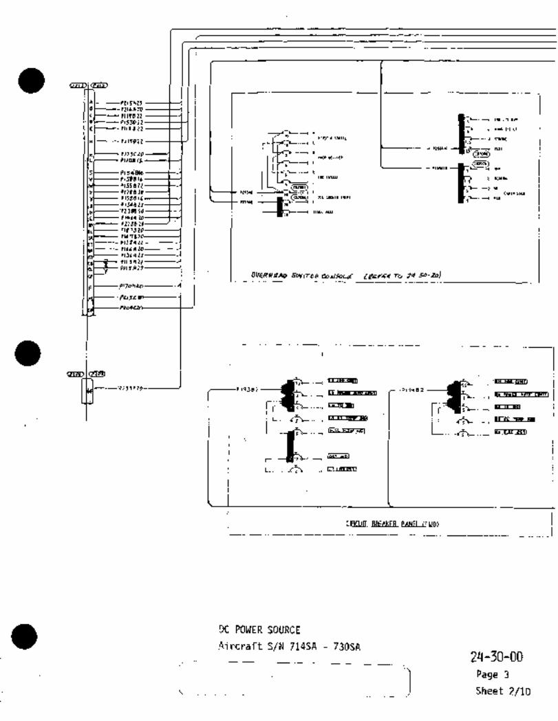
r Iw LTI OLI1
e~-----’PtltnLO
0 5JD 22’El PIIIBZZ YIN6 ICT LT
Plmr a IT1~IC ITaDal111--0117822 .s
SZ5~10 -~b--) a~I
*~---P12JCZO (cs,osci)paw or-lew
´•ILI ’P110814(C112(116)
PPSIIIO UV
I I IPlsbels----$--´•l I I I’ II I, ..E"’~Ut p;p--~ s~a
rlSSBZt i ~-;b´•----) NS
6 P129820 p25ua b-----1 CIBIII 5101
m~ I,,,,,,,,,PIS~L)P25UlB
0154022 20
bl ’Pt jgIl 20- IOb.-~ SaLL YIIL
e146A
SUVlTeO Co6/SoLLT r0 24-50-20)I
Pr288
P1678~P1478PIJg~ZZ
’P106AP1j6AL2
PIIJAZI
PIISA2Z
pu3a
I -Ic~D I cTTm,
warr~wn
1´•lm Parw
´•-I
’P2J9RZO--------~ 19402.3
r; T;: rrr~sasl
i i----b;b-----e
rCff_lgUL111PI
L-----b~b---.
j_ PANEl (FWD)
DC POWER SOURCE
Aircraft S/N 714SA 730SA2~-30-00
f
T?! Sheet 2/10iPage 3

-----dt~b-., ´•~mm
r´•heaem rC]
~rm
´•suhaen~
I! itI C1
-_~wasaRI
1 ;b.., ~erPMI
I --I
r
L~y uCIC CPIT I56-1
I
LI_ rL~* UIIN Y*LV_SJ
s ~fl i_ J~L I
r’II
I PIIY\~
´•r
~b- I IY- L*E. Pl.r CI´•ICFI
I
Plr~as ~,.lvlrt 7E-ICEIr
;k.- L~L( ly~ CP*n
P,Suls-~--C- Ladj~P.wEal
P~soslo
P)91blPlole,b Z.~FI_L PIOZCI16_,,,,,,1 I h~SL L~
bl´•7ar~P~I1LI
1 I I I I ,P19qb; ´•---1--// rICL*IQ
PI*l~lbI---ft/ I I 1 11~1
I L ~k..-P,r3E ~I
p14~bl
_~
5
L
CIRCU)T BREBIIEg MNUtCENTSR)
DC POWER SOURCE
Aircraft S/N 714SA 730SA 24-30-00Page 3
Sheet 3/10

~P,
Bblblli~C1ATOR .PANEL .1R FEEPER ODT I IJ~--’PIPBAZZ´•(FWf) OF I_H SIDE PANEL) STA 9050
´•I~ FEMEROUTI P1~9LIZZCELI~G
.IR OC GEn OLOI
Ic oc
P117R12----~ llZC---p117DZZ
P153AZZ PIYD2Z
LH FNGINE NALE1.I.F
PleZA16
i I I E---:p 161422 ’´•liS~--P1618 22
~mD I t~o IPIIIAZZ 1´•1211 -PIZ I B 22
p/99Rli~ ----I´•~ t---P/PPBI~OA----P12A16 ----~---lel 16 5 :P160C 16 PlbOB 16
I. X I’-PlIAIb P1S2A22 P152822 PISZB 22
X-a 9--.- P10~16 ---(Hlt---2-PIQSC16 a--lslt-~------P14SBIb PIQSA 16
C~-----PJAOBLLEILIL~I2 pll7err----l (36t----P)lrlCT~Z-
E -KII110 --1 r RBEZL
4AON
LB PZAO
(ILfLS) I(5171)
r a P ZAO
csue,
pioiAa ~Pioiso
’P4AON
E 20LEblSEBhllbllrflEI~ LB~
n4---´•--~P10A16
r’PIIA16 12AZZZ--(IZI´•~------’P1 IZBZZ
D~L----PIZA16 ------------lel- ~----2-P129C16 16
rc~
I´•~a ~I Gi~jy) )A z
IIBRIERp141az
--ic~- plSIAZ
GEbl~EB_bLLELG
142ez:~19ZAzEaBblLtBfllRlir .P19QAz
DC POWER SOURCE
Aircraft S/N 714SA 730SA24-30-00
i--~ Page 3
Sheet 4/10

´•REVERSE CVRRENTCVTOIIT RELA‘I(RH)
’Plo/E16PIOIOZO ’6EN
PIOIBOP107CZ SW. t-----KIOBAO -----d
(IOL) l~z
P211820 INO o*T PZISCZO
P2208Z0 1JAZO
i I I I I I P1OIA20 3820P166AIZ
P135A20 I c~s, r---K 13 7AO ------ifPZIJB20 !´•n’Slilllllp/8~A/P
Z16CZ0
i I I \I\ It I II
p/PZAI J
´•Cr~sr)rnlsm
PrY~R/d 7PwP 20
Z\3hZO(A~
:PZISC 20plZOB20 I rZILAIB
pisqAto ~174A20
C11 (E~3
~D Cr~I I I I
-T;
I´•\ ´•1. IPZIIA 18
~I
)il,Rz ~i*PR/b --~-PS P16380
--~UVP ~,J
I I I I I ´•lu
’pisl~zo
PZIIAlr
7J820
P/ZP 174420*t
p/qpn30 -----II~U (p+19) I rS----P18SBIZI I ~’PIISG
P/PB~----´•PIXD -8*T I e-P164R*t
P170Ezo
~rg---bsw I II ’Pllanlo
p14/E 11
P~DM PI(JA
so ccrrw *I
WTOVT
DC POWER SOURCE
Aircraft S/N 714SA 730SA´•24-30-00
j Page 3
Sheet 5/10

MJ 8.
p,ggSIZ
plr~zr I,P107BZO 20PIZI 8 Z Z ----1- IP PILI 0 Z Z
t--´•P? 20E ZOP147 B 20 ----1 -Iclt--- plqlC 20
91616 ZZ ----l-(Kt--- PI~IB 17c~a ----.J´•(YC--PZZI~LO
PIozeIgX PIOZC16
’P14ZB16 P142C16PI56520N ~-I 16CF-P156AZ~
B~pl) IIP--t-tS~--’PIT7AION-t-(PI7PA16 -~--I’ IABt-~-P 179LlbP~lpnzz -f---l- I~ zz
p,54ezrf-~ JP)----tPIS4C22PI-5S822 t----J )Z ~--t P1551 22
5C 22P146AZOt--I l~t-tP146L ZOP1?OHPO --C--l re C-CP,iohlzo
PI~LOZ Z ~---I I t P1S Z F ZZP14 SE 16 --t--l I v~---t P14 S f: 16PlbO 8 16 --~---1 p IbO E /6P119822Plabn2a 21)
P1?6AILPl~bA22 --t-----l I i P1~6( 22
~P,lsazr t---( I-s~---C- pIlac zr
IIC--CPllbAIO11131122
f--llrC-F-P,,6 a2o
PIIZBtZPIOSElb ~-----I´•IIECCPIISFIL
129816P2 3B820 IM)~---- P2 JBA2D~s164 4 ZO ---t ´•IAHI----P 164 G ZOPISJ622 -----((H~P15‘3F22P1I7622 -----(ILC--PII7F 22P2J982d -----1´•lhlt--P239AL(I
I I I pit 0 8 Il ----I IE C--~PIIOA 20P/34 816 ´•IF t--’p IJqC ZO
-1i58816 -----l-IJt---PI~ICIo1110 816
I1~----PZIZAlsP170H 26 ----1 IX
P2IJEZd-----I (St----P2N620P~(6AZD----IISC-- PZ16C 20P 21SAZO (U t--PtlSCZO
i´• DC POWER SOURCE24-30-00
Aircraft S/N 714SA 730SAPage 3
Sheet 6/10

r PIIOAZO PlOqA
P//4~ZO -7 .IRU ~rlHET00I B
P1)4CLO----C----POQDZO --P135A
p/PBDI’Z p/PdBIO(~d)
----~t----P/BBBZO
.Pld/DM
PU3~92D
P/5~C20 --t----Pl~ir) P159AZOI B
o G~P/mRm ------r;~----"pAlo
PIIOBIZ ~----1
IZ ----~YiSb---- --1
~na?u -)aiiEKza~
P131E2C-;rlBs8 !L
P139FZO
P164CZO
IIPILO
PIB(1PIZ
~I17TmTrriCI
rob(CL127(1) ~CIERRE(EPI
r18LIA8
(i8286)
Prb----PZIOAIB
BREAKEBSBhLEL
OAircraft S/N 714SA Thru 7235P~Aircraft S/N 724SA And Up
DC POWER SOURCE
Aircraft S/N 714SA 730SA 24-30-00
Rev No2Page 3
Aug 1/80 Sheet 7/10

i´•
C~D crllb) N
N I I yl
~-----Plssnz PIZ~A20------NI I I Inl 1~
PISQC ;Z ]X( I (K[ PIIICZZP1SZC ZL-----IJI I I -IJC--- PIIZC2ZP131C 2Z-----1HI I I IHt--P136C22P153FZ2 --~FI I I IFt--PII7F 22
P179L16~EI I IECZ’P176C16’P146CZO--t~0(- I I .IDI 1 I11)6CZO
P14JB?D--t--1CI I ICC--CP1038ZOP ISSC 22--t--~ 81 I I -le’ ´•P119czzP1QQA \A~--P104A16
LL~L IBtP
O~VERVI)LTA6F..RELP;I
ezrae, ~io
C L P119A16K K
P143A Ib J P103A16
8 H
PIS’IBZ GI. G P1168 ZOF F
ZZ E E P113CZZPcszEz2-e o 8 ,P112022
0 0
14 ID to B i B PlOlt~ZOA A
ratu r~tu
VOLTA6E RE~IYLBL4R
P170NZO
01420
r17BfZO----~., .i~C=P11062070E20----~ P178A20:PI ZEE ZO ----~C’PZ~’IAZO --.iio/r 23SA 2[)
II
~----p 139E23si0 P10382
43/\16 u p103A16ZC1b P16ZCI~
P14SF16 P105F16
~I P1240,6P160A16 PIZ9A id
´•~LtJ) (Rti)
xI
’cB´•1~Y c~e,CY11)50P179A1L P116811 -----c~--P176A16
5E16 P1OSE!6
P145A16 F105816
i’-DC POWER:SOURCE 24-30-00
Aircraft S/N 714SA 730SA Page 3
S-heet 8/10
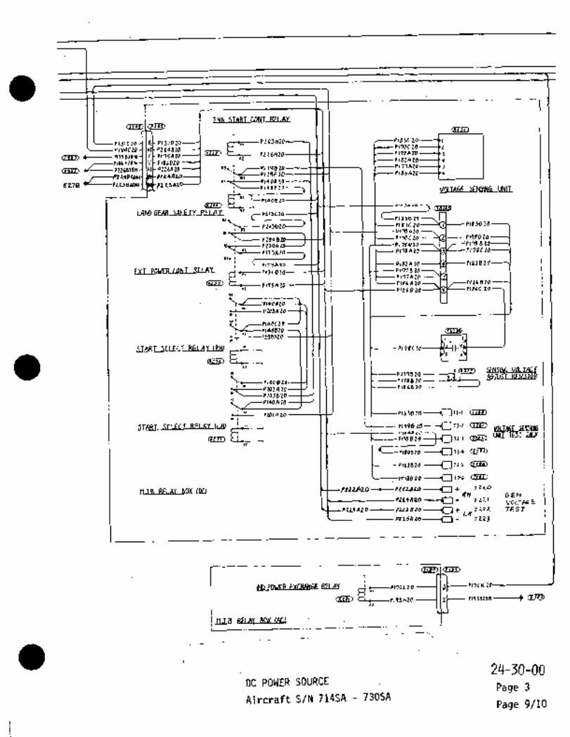
1 ‘I
EN6 ~TART CONT RELAY
I II I
131CZO .PI 310jL to----C,´•
´•~IP170G ZO 2~Z04CZO: .PZOQB t!
CE~’ P~75ezoN-ll’ ~P175A20 G~----P226A ’P 178A 2(1 ----C 3*2 IILA t
r))6tZOn P1860ZOP226A2b 8)t: ~P1396 177420-iC S
PLt ~--P139F ~Plf6AZO 6-
s, ~I--’PIQOAE~78 rL~5B2W1 rWbp225 i~----p 140Ft0
I
--’p1~9A10 --)~PXf
~’p113C10----
st ~---7 ~-P I I)B 20
hc-.PL13020 PIIIJC 20 3020la PI’IOAZO
r20Q B PI?DCZO
12044 172820 :P1788
--.P113A20--7 P178A20 P178C
´•bl´• I
C.p17382o III I I IEXT POWER LONT RELAY ,,,,,z 1’17820
tt :P117A20
.PI’ISAZa PI8I A P186Bxr :P1860 P186L 20
’PIQOBZO´•sl
’P263420´•r I
iii /-P140C207 I I I I Qn~Yu
I u
P178CZd
~hc--.P1408 178820----j~ul--7I ‘P IB6820--~------J
i~--Pzo,e 20;1! /--.PIQOA20
LL-- P20I FI 20
SLSBLSELELLBELBYILtl,
-r
´•pisaazo UNIT TEST JAGK.
.CILZ4L) ´•VOLTACE SENSING
P170 B tO TJ-3
:P18(B20 ´•cszaj-,
PlO2820 -----a.TJ-~ .G2244)
-P178D20 ---a´•TJ~b
´•nJB RELAY ROX (f~U PLZZALO --11 -C rLzo
RH GEN----~CZJ ~i?21
VOL7AC4
LHsznr TEST
pr25ArO--11- 3223
i rIND.POWFA EXCWVICE RELAY
C~ I ce~u
P170L20 --~.ISt----P170Kxitl
a~ (I .p19SA2O llr
A~LAU ROX (A~
24-30-00DC POWER SOURCE
Page 3
Aircraft S/N 714SA 730SAPage 9/10

ST~HI
~3D .-r rP1~2AaP12?eo ----4ZP---’P127AO --~i’l ’PIZZFlb
I 12 2 B 20
N0.1 RE(AY ~k-XL--p 18 7~20
nbca~Q~ Cid--PIZ)BZO
´•xt
TT´•A1e--- PI 32AO
PISIA2[1
p,j1sra
’rI)’IAZOrr
´•~PD~r
A’ I ^/1 .PlbZ/IBP165BO
r ~E,(EfD tid----PZLgAi0
~Pia380
aeru
ir---.Plb~ero164820 Pla7Aza
P131CZO -~t--plsls 20
.P1~3CZO P12J820----~
i":P122C ZD
´•Ip----P137820N 37/(20
PZZB~ZO r229A20 r1 I I /----P126AON
P12IAO
’PI1BB :PltBAZ07
Wlpp~t..ccd;s’b--------PtZ
o~,, .P~smo
e,PlbJAO
´•~’--pnt
:82 ~ee,
P133~0PI
´•nlc! At
´•P1I2D2DV .PIZZC 20
P132AO
ELIEBGh~CY_BU$Y- .-l´•L .P122E 20--J I -T1’1~0A2o
´•QE~ r; -P128~4t0*1
Pls,noa=Zy,
BLZU_SLIBIGALLnnePIELBL~MLYtli_l
DC POWER SOURCE .24-30-00Aircraft SJN 714SA 730SA
Page 3
r Sheet 10/10

PIL~TSSUIP*IILL ~-E
P299B20
CONNECTIONBOX
ISOLATE
b-ONiP228C20 ---4C~\ t- R646P228820
-=q 8AT#2
IP299B20
NORMAL
ISOLATE--7 O
CP229A20
(S209~ 46-2 P123C2015209) ‘b 6123020
NORMAL
P229A20~-- P124A20
BATTERY KEY SU
EMERGENCY
ZL:~ASTER SW _1NORMAL I__
(5843) ~g BATT TVIP
+28V DC Dt-- PBT-19B-20 PBT-19A-20 -s~J28V DC
L/H LOADBUS
LIGHTINGZBYDC B~-- 8T20A20 ~e 28VDCINSTPNLLTCBUS
GI BT21A20 8T21B20 -7
TEST I I TEST SW I
KI-- BTZ1BZO
JI W2000820 :W2000B20
NI W2O14B2O. W2O14820BATTERY #1
LC BTZ2120 ----ejj3~ 237-20 231-20
BATT TEMP
97.6KR LESS500SW
n~--BT23A20 238-20 238-20
BATTERY #2 W2013B20H~ W2013820
RC- 239-20
GROUND P 8T25A20N ----a(ll
LIGHT GND EC BT26A20N
MASTER WARNING BT35AnF BT35A22
1200 OUTPUT SIG. C
BATTERY TEMP IND
BATTERY OVERTEMP WARNING
Aircraft S/N 661SA 24-30-10
Page 1
Sheet 1/2

W2OO0B20 W200OB20 ----------(BNO.
STAeans
W2014820 W2014820 CBATTERY
237-20 237-20 -----14
239-20 239-20 ----------1C
W2013B20 W2013B20 ’B NO. 2
BATTERY238-20 238-20 ----14
P228A20
BATTERY
P228B20 P228B20 RELAY
P123C20 P123C20 P123820Y BATTERY
RELAY
I AFT BA~ERY tOHPI
ANNUNCIATOR PANEL
L/H SIDE
(5244)
W201822 -t-lhW2O3B22 --k--(fW2O4B22 -~etle
BT31A22
8T33A22
8T34A22
PISTR YRRN AOAPTER
8T34A22 ---IAl HI MSTR WARN ANN
BT33A22 D RESET IN
BT31AZ2----(C 2BVDCPWRIN
8T35A22 ----I F WARN IN
8T36A22N ´•--(H GND
lb-- 8T32A22N -181 LO FISTR WARN ANN
BATTERY OVERTEMP WARNING
Aircraft SN 661SA24-30-16
C-Page 1
i Sheet 2/2

AFT. BATTERY COMPT. r--1
BI(~I:YI´•I
5213
A W2007820 W2007820 H EG-8
BC- W2005820 W2005820 ´•----~Al C-- EG-Fi --1
CI-- W2003822 W2003822 -f II I- EG-7
NO. 2
(5842)BATTERY 5842
A~-- W2008B20 ------_------´•- W2008820 ---IWI EG-4
BC- W2013822 :-------------t--------- W2O13B22
c~-- W2014822 W2014822
X2P228820 P228B2O ---IAWI C AG-46
’K313
NO. 2 BATTERYP228A2O P228A20
X2P123820
IP123820 P123C20 P123C20 K AG-2
RELAYX1
NO. 1 BATTERY
W2010820 --e- W2015A22 --D
CONNECTION BOXRELAY I~__
F.S. 3050
CEILING DISC
5288
W2014C22 W2014822 I ANNUNCIATOR PANEL
iW2013C22 W2013822
BAT TEMP 120 T :W2013CC22
’BAT OVER TEMP Vtt- M2014CC22 ---i
SPARE U
W2013C22 ~W2013C22
W2014C22 W2014C22 ---i
BATTERY OVERTEMP WARNING
Aircraft S/N697SA 730SA
T_ 24-30-10Pase 2
Sheet 1/2
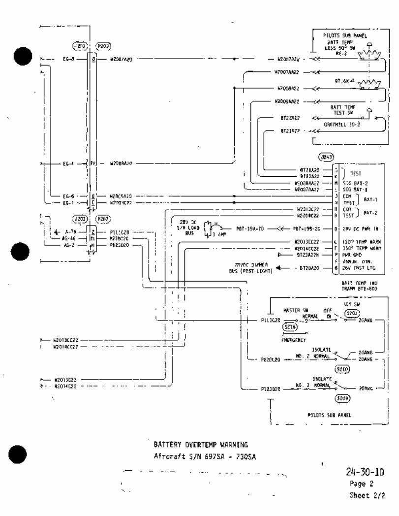
C__
__
rPILOTS SUB PANELP 15203 LESS 500 SW
RE-2t---- EG-8 ----I D/-- W2007A20 W2007A22
W2O07AA22
97.6Kn
1W2008A22
W20O8AA22BATT TEMP
TEST SWBT22A22
GRAYHiLL 30-~
EG-4 ii IEE~-- W2008A20 :I _BT21A27 T--__
I
5843
BT21A22 GTEST
BT22A22 K
W20O8AA22 --IM SIG BAT-2
W2O07AA22 L SIG BAT-1
EG-7 ICI-- W2003C22 ---t N TESTBAT-1
EG-B U W2005A20 5 COM
r~--------H COM
W2014C22 R TESTD"’-L
:II’Z5202I I L/H28V DC
cg;i~ PBT-19A-2O --<t PBT-19B-20 ---ID 28V DC PWR INA-7N PlllC20 BUS 1 AMP
AG-46 P228C20
AG-2 P123020
BUS (POST LIGHT)8120A20
Ei ANNUN. DIM.
W2013CC22 C 1200 TEMP WARN
W2014CC22 F 1500 TEMP WARN
BT23A22N P PWR GND
t-- __
i28VDC DIMMER
B 28V INST LTG
BATT TEMP IND
TRAMM 871-600
(5202) 1TER SY OFF
KEY SW
5202NORMAL CN
PlllC20~-------oISOLATEo
ZOAIJG15216
7- t(20T3CC22 EMERGENCY
t- W2014CC22 --_----------
NO. 2 g r ZOAWGNORMAL -o~oL-- 20AWG
z- W2013C22 ´•P228C20P123D20 ISOLATE
ZOAWG
i5210
W2014C22 NO.1 NORMAL
5209
L PILOTS SUB PANEL
BATTERY OVERTEMP WARNING
Aircraft S/N 697SA -730SA
24-30-10
i: Page 2
Sheet 2/2
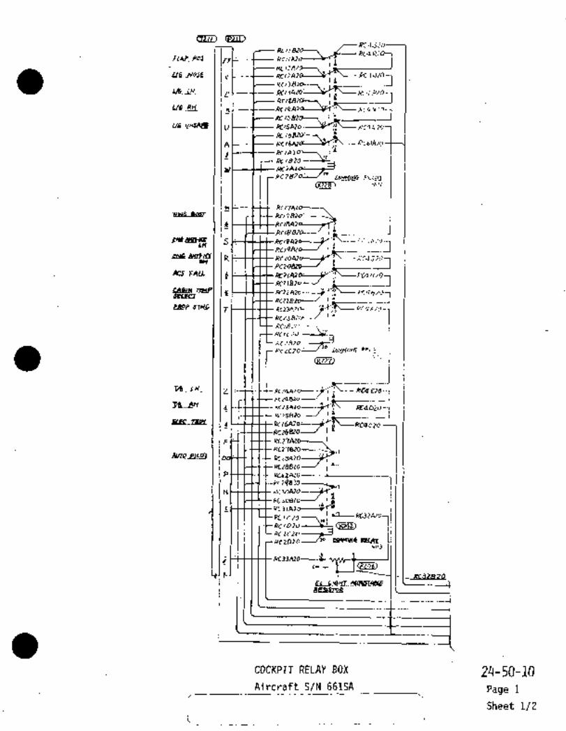
~zLU ~21l)
RCI/B~’71 C-RCQK;/IAP~Z Rt,
V RC,If
)4C’’1 4,’0llIIIr]Ln; 1H
p RC~ RC´•~ t~o-
LL6~ RC(I´•Y;!
RC I~
U RC,SA20: /5 ~ZC?L
i
A RC RC61AL~
Y RCIA20: I1RtlB24
dt: Rfl
RC7BZA
CK_Z18~
n ReWIN6 B49T RC178~o-----
R pc
Rc18 II.f~dlBUB S Rc14 ’:i´• i KI’Oi
1\1~117Ln Ii
RtZoAl RCQJ~i)rW Ip
c\cs r~le d Bz~Az I X’GQH%ORCZIB ,1~----------1
U j.’~8YgI7
RcnSZ~--/ r;e __i/a
T Rcz3Azcl KCQ~ZO-
RC23
KcZCZO
tb Lrl_ -LI;TZQBzo---/ I
Ehe~. iZC25A20: IffQD20Lu-lKCZSB2O:1J´•
Rc26AZo’RC26820.
F RC27
to
P RC6fALO
N h‘e
RC3142"’
.RC/C70 \,I
RCIDZO’----~RC2CZo"-j;bczozo’ /’O
3
eve
EL
R~CrroR
---------i
COCKPIT RELAY BOX 24-50-10Aircraft S/N 661SA Page 1
Sheet 1/2
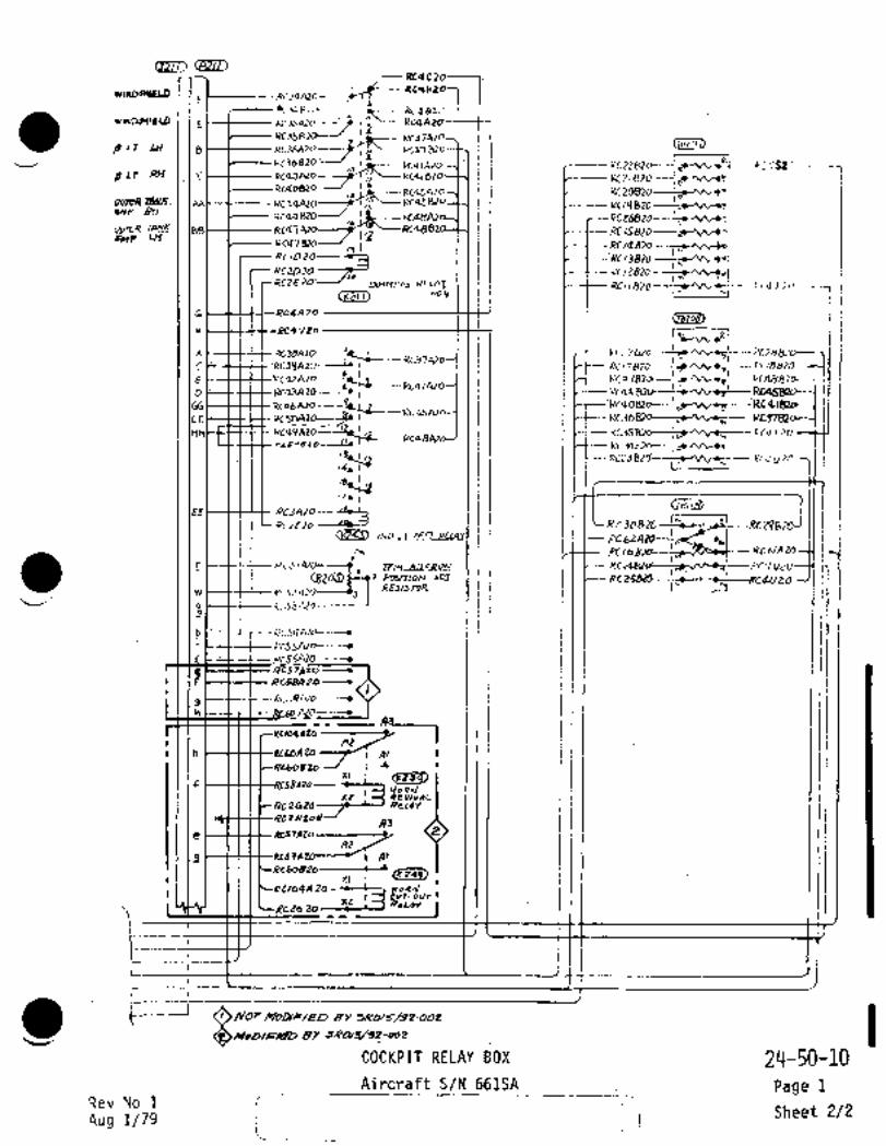
~D
RCqC:"91WIIIDS~ELD. RCQR2i ´•RC3a
NRt(l411LU)
KC35s2, /137
KC~37AZO
60 LT ~CH I I B t~Lt---KC36A~O----7I
PC37’BrzI~C6aZO/ 1~5;-----RJIA20 PC2Z XC’iSZ?
BLT RH Y KCQI 820 M21BZOto p-
ii Ir
~X- Pc45AZor ~V 20820
I.E --RcQS~Uo: I"
oYp Bn ´•Rc4a~o- I_,. i
OurtL4 Rc~7Az~ I ’PC15EMP Ui laRcq´•lezo---/ ~RC/Qn,,,,~,
RC13Ble-:n"~,RCZD2O--~J RC/ZBZOIm
Rcl 1 820 kca. I~ 0
(t(Z4;1) Nov 1-
61 1 177Rc4A 20 1171 1
i I
K638A20------~-IL ’KC 7 EVo- FC28B2~
C ’RCSq39L\~OKC37
RC 17820 FC,R8701---~KCQIA20 R:QQ RCQSEPD---~
GG.C 4182~---1I RC I" ‘I
KC.3 ~---1__
~.CQ .rZO:III I’ I II I
pc:S Bzol K~o u;O
*7´• 1
E~RCZE2O ~Le.J II I II ILRrjd8ZO
C~i) /ND I I I l-FcszRC6/PZOCW RC16
r 11 It I(BL~Z) RC
I’ "IW ~--CS--ecKtSZA
I Igb I-I--I-CI-X’CS~Ar(r----´•
d_6 t--St+-- 4C57AZO
Rcs~gZo---´•
ghi C--Rtxo ALOL---´•
RcaqlZoA2
h 1--+ttacboA20 i Al
xl´• (KT5~q)-F
´•II clo9Jlr Rev~vnL
kceaza
Aje CH-CCas´•rlro-------L
g I Al
RC60BZO1.1I I I I 1 I I~ICptlagAZo --Lc--fj´• I
Rc2s 20x,r
t---JOFlbD/FI~6tiD BY
COCKPIT RELAY BOX 21´•1-50-10Aircraft_S/N 661SA Page 1
Rev´•No 1Sheet 2/2
F\ug 1/29j

azru
rliCIIBZb--, /-RC
´•E1Ae-~r rlN~ RCIRCQRi
I~U6 NPJEPL~,
RCI RC4BZ07I~j
~cTRe B
I~ieLL72~ ml~HLQ---W:I L- RCQAIZ(I;-,
~!i 1
I Iv IZCISAZO. XC4 1~01
Rc/6s~----\lbBLLlf A RCIMZOL----Y7 ’-R
Y BIAloL-~ ~IZRclSzd
’i~F---~-- AC7
RCZBZOL/"NOI
rF-t$t Re,
jl-l
Rc/B ri4u~ I I$ ~CIP r;’ .PC4
RF: RcZoAz RC4JRH 1P
u RCcl~
7- Rt~ZO
RC238;1:7
RC/B24 L1
Re zero
RcZC20--/"’Y02
‘Pb -I~ Ilais
F1Pc26
dMq_PLCqT_( I r~LLLIlI^ ac/d
BATfP~ttfS-CCbtIYARNI
N I-
s
,RCICZO
RtZCZo----~JACZD20. /’O
N03
j
CN c I(PIZ~t
c
Q 697SA 713SA
O 714SA ;717SR
1 C_
COGKPIT RELAY BOX24-50-10
Aircraft S/N 697SA 717SA Page 2
Sheet 1/2

cs~ioRC~
L RCQB207-Rc3aATo~
_1. IPc RCQBUI--JKC3SAZD RCCAZO
i-pLr~ Ils
RC36BZO---/ i’_ 841A70: :PC22 RCQSZOklt.Rt~
:RCZIRc4aB, Ir
RC45AZO: :PLAAy RC4 I?
lae-Rn I? ’RC
IBet~ RCQ7 .Pf~5 I"
----Rcq´•l I’
;PclZB~O
?31~RCZEZO
.RCIIBZO14
RC4~-20NOQ
G RrQA2D
Rc~4Y20 VB~
~´•/\ILae
RG37c .41~6iRe42Ato
17 :~Q3A20 I´•
’R"bg"-isp"c-%;--M
RC3SBI-,,,,,~ Rccrzo:
~S0nm/iV.-´• I IJ PUJ RcqUZOI- hi
RC3AZd---1Pci III I I fRC~IO -7~-=1 1 i I U--Rcjoe ~C-RcZ98RCZrZO
cw RCr6 RcuPu,
II ~CTQ.RC ~C/ZO
w ~--$-t--ttRCSZ 1‘T y
g i-3-t3t Rc59A 2/3 --1
b RCSQA2´•o-----~
20----3
3 RCSBAzoO--~A3
AZAl
161B
O‘S/N 697SA ´•713SA
~ec OS/N 714SA 7175A
AJ OS/N 697SA 71754 UNLESS MODIFIED
J BY SR015/32-002
AZ ~S/N 69754 717SA MODIFIEDK Al BY 59015/32-002
------ca IYJ~N 907~1 i OUT R,RLA~
LILNUH-(a
zF
--XT-5
is 7’7
24-50-10COCKPIT RELAY BOX
Rev.No 1 Page 2Aircraft S/N~697SA 717SA
Aug 1/79 Sheet 2/2

I-
FLAP .poS rc~Am /C;--- ’~aRlc,
I
L/4;( NoSE Vzc/ra~´• 1
i
LH I (P Pc~m--?
n´•’t
L/GI a~J.uro´•---, RCIS~D
;eCM4n, Yr
~I----------- Re
L/Gr U~SAFE U Pc~CD-icuslo
I ´•x ISPARE A Rc~aro
M,68m-~Algaro-~c/am
\E\o LIT illpyaM
IPCCBm
."t"""
;ec/ram
jXQYmI I
pclaa2o0017810 -t~
RCo
ara~am 0( 058
RLdbB~DRco,azo
a I1nc,an 10 at369zo
S RC19410.6
SVAi(E R Rc2sn~o~av x~aa OHE RELAT
Z KC14~2D I i iA
i --i ;C----I
cAsIY TEMP kcl2nzo
iurt~o’Ir
PROP sYNC )17 nctja~o-----, I~L--aC4EZo
"RC~SBln´•s
ELEC TRIM S I~--KdDZO
AUTU P1LOT i F ~-----+tf----tt R1 774’0 (lb
PC28*~0 i~---IPC37BIO
R(;fB~O 4~ai
e AM ~--------L;i’INAsrH: C4LmON~ N t-----tttt‘--tt"’PC ~D A~O
Ft LIT A~3UsTi~I;pcJzsm- r
;cU3Z~b-;ec/sm 2 ;7
’yc’K
L~COCKPIT RELAY BOX 24-50-10
r.______Aj,,,,flt_SLMIIsSA-Z3aSA___
_\Page 3
Sheet 1/2

i
~w
i ir-jrjon a B LIT (LH)~nm
y B LIT (RH)
/I~´•IQAm: OUTER TANK EMP ~RH)’M44~m’-----/´• ‘i~L-
OUTER TANK EMP (LH)
(LUSL)"p"/L~r,
I m
XB LIT CLH)
ars7m -C--CC-( CE jp LLT (R~I)
----r=~:;rr~Jkm´•i I /~I IJOUTE~ TANI; EE(P(LH)
U~"44.
´•i~-’"UI
-C------CC-IEEI´•I IrJp Llr TEST
´•ZI´•aLUclMyar -´•,c~Em
m\i-~rrm´•
UI ~mlH mt pW6
K
A~c´•nMswr ~-´•r´• ´•´•~cr,,´•-, I I I I I II~HoKEI;a-
*23q~0´•I L
HolIJ f
RC4 V2O -------I H 3acon2o a,
I´•´• LI~HTINEi
----1KII~ SPAKE~aourloll OVBP1EN67W
24-50-10COC’KPIT RELAY BOX
Page 3Aircraft S/N 718SA 730SA
Sheet 2/2

´•m~QCd 14UIIFo ioc P~IVC(L
eB O"C2 8c,aQLU45RZ
Imll~pl
LV45AZO
3 A A~IK6 ICd
:zYLI/N LCIII~PO
LI~ZT JO-PO-L*) 5
W.s -~u-Jo L U ’1ZA 2
~F;
S P PTTL/A(600a 2
9s-4o-Io PTTLEAI60Q (5 P,W~BO
ILsolnlbO PI5Ln,
B B B LUL5AZO5 pu´•7a Ir
T 5 r LUII~´•:OJ3-4L~-LD
cJ U U LuiSJAi
L L L. LV31A22eoo~ LIGn7K9 5
c C C U32H22
-H´•IV ´•uv uZIAZZ-----------
t-l 1D~- -H lott-Luzonzz--------, I
PL)lbLILC~ E‘s
E LU13AZZ-------oC~zlij
f-IIF~- +-liF LUZ4AZ2------o LfLI
c_(C- -CI Ic C- LU2P422--o C~j~78
bl~ t-l Ib t-l IbJ--t--LUZ4AZZ´•
-C-l Iv Y IV41A?O
GI t- -H Ic L(I~IBZO
HI~ $--t --Wlyt----LU4P~
x L114liZO1i: X Lu4-’AZ
/IYJT4unW7~a~o
"I IJ~ ~J IJt----Lil4~IA L~J4(DZO
33-/L~-00
K1F- --I Iic LLIJ-IEZK LU46
JCD-P)IOT FLT INS~-lLitnn~ LU4, G20
M LU4IF’Cy ~uj7nz
I-- L~4/6A 20 a.a LU48AZ
LL151~20
PQ-go.jo
LU48820
48CLIG~\TEO
P~E?.
R
uZ14 17 QMRriT6R
e~oT/oJ S
JJ-/o-ro zz4zz O
O S/N Ld/SA, ~97SA 7K´•eu 7/35n
08~y 7/55A 7xRCI 730SA
~S/n/ 7/aSA
r-
OYERHEAD SUITCH coFlsoLE 24-50-20
Aircraft S/N 661SA, 697SA-730SA Page 1
I ´•Sheet 1/4

LUdSB2C
I IU I I E 2 0 U 59 BZ
(IL165aZ
u I O J Z O H u I 1 SzZI J~-_HIII?AZr’
WUZIAZZ O01*
~IUIOHZO---~C31nUI? AZZ
cl~
vlo G- 20st
c165
BI~
UIOF20
HL)59AZZ
CC-~-L-_LC145BZOINO LTS’DIMMING CT~- \---LV45SZO-----KELAY rJO. I
U10L20
I
HUZ68ZZ--JJU I I D zON~Hu 588 ZZ
I I
JhlWl~t--HU"48ZOI ~----Hu64A
u I I E 20I h 16A Z~
U IOE ?0 --~03
02HU16AZ
UIOF~O
ol~
U10020
n~lc;qAZ
U 10 C 20
CI~
HUP6BZZ
HLIZ5A2ZAI~
(Ki9_3~ rcc-- L. U 45C 20
IND LTS f,lMMINi, rL/--U i 0 L ZORELAY NO.Z UIOI(Z
UIDCIO
ICAZ2
LL~11020hl
LL141C20
wUzlA220
O S/N 697~A T~u 7Ns;g
OVERHEAD SWITCH CONSOLE 24-50-20
Airc.raft S/N 661SA, 697SA-730SA Page 1
Sheet 2/4

/Tr\ loll COOLER INLET C1U65820
T~YHU63AZ
ilU15422
jOlL COOLER IEIIET -~j64020----+161~----HUG2AZq----7 I L HU 63 A20
(osz91)IENG INTAM LJHU57A22----
1’1822 HU15AZ2
I~TAr;E RI I rS----------HU24A22------1116821 HU14AZZ
(psze~IWINe M-ICEIuZ5822 UZ4AZZ
HU14 A22HEAT LOW
u54822 HL/5?AZZ
VbZA20
HEAT U)W R
usBBZZ Hu56AZ2
HUZbL\22U 10 C 20
IST*LL v4NE]
10 u41A18
LO’\. COOLEPINLfTJ I llIleEoI\I
ROIL COOLEII INL~T 3HU~SBZP
n90A 100 U10820NOIL C9DLERI"LrrAXn-,ceX120-/0
HUsSBZ2 20
IENG INTAK~ Z1------HU64BZO a 5 b----Huluzz
--c- IEN" INT~)tE PI-~--HLllbS20 a j ~------HUIOAZt
(cezag~ -c, IPRoP OEICEC LI
DC porv~
I I X (PPOP DE-ICER R I
I IPI~OTB STL\TIC LId,b~----;-FI733n 18-
P IIa;0~b----FU 31A1
ECGE LI6~mD
~PANEL (Ln)
Lu48CZa
MJNB,B N--
U IOBZON I I
iVIOAlsNvVLI4I L\lgHJIIArZ
U10~20N I 1 I ~ul I ezoN 00 IOA 22--l/IOc 20 13818N HU19 A ZL
wuZ&a22 (E245) (IAI
HUIBA 2 2UIIDZON
FL133A ~8-----LU4/C2O
FL13~A18LuqBe 20 u rO A la IIl
IPlfoTLL ST*TIC
cSobA’bF306AIa -------I FJOSA16
o,j b-- N054/6
O S/N &L/SA. 6975R -rwtu 7/J~iA
0~ 7/4~SA,
s/´• 7/J5R TA/ru
rs/r/ Nbr~so/FleDBv sRo20/94-oos
IHoolc/eroey bRoZo/34-OoS
ri
24-50-20OVERHEAD SWITCH CONSdLE
Aircraft S/N 661SA, 697SA-730SA- Page 1Rev No 1
Aug 1/79Sheet 3/4
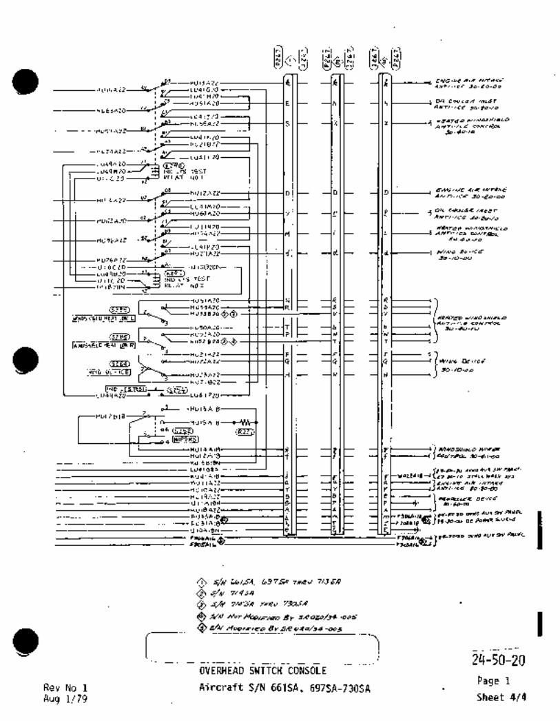
__
~----HU 13A ZP R R AIR
HU15AZZ ,,41Gz0*NN-ICE 90-20-00
LU41 HZO
UGIAZO 1~El --(lh OIL OOOLOII /NLET
L)AIT/-ICp 50-20-10
LU~IJZO
55AZZ-----~--f---(S I IX WEATr~O C/IIVDJXldLD
ANTI-IC~ COIVT~OL
~b-lo-loLU41K2O
~1
~-----Huzle2Z
LU41LZOLu49AZ
L U44 5 INO LTS TEST
U I I C 20 RELAI NO.I
HU14AZZ
A/Rf) D D
90-20-06
U41MzHU60AZO vlC ~P I C- I_P OIL C001~R
ANTI-/C6 90-20-/0nU62 ci
41NZO
nU56i’ZPLU41PZO
UZ1AZZ d dlC --IldC------I WIIIIG
hu26AzZ 90-/u-uo
UIOCZO UIOB
CKz9 I)iU498Zu I lC 20 INO LTS TEST
UIIBZON RELA* NO.Z
N R 6
IWINDSHIELD HEAT U~ RI L~HU50AZo TI~ b J;Jo-Bo -/o
(3235) OC--nU53AZO R 5
HV5382000 V YATpp
3 4~TI-/ca coNT~CaL
<5256) oe--Hus7A20 P
~HV52B2000 T T
----IFI~ --I(FDL~-Hy2ZAZZ G
WIF~G DE-ICEI2 ~o-/o-oo
HUZ3AZZ H H
nuzlezZIIND LTSTESTI
LI4qAZO---4 ´•~----LU41 P20
-3 MUI?AIS
ul2815MU15A18
06 ´•(R~Zli)
4IWIPER3]
ulZAlb------f--t---rlf FI~U14A 6
61 C I u tW422A 18 JrcLL wao~ Jy~.
--´•I In I11 /UTAAaL
II C --´•I vl´•C- --I IY 50.20-43
P
A3B OB-/rd
P B-LO-4D
111 pU-~Mo cVHD 501 SW ~ILleL
I 21 JO-(2~ DC 20936 riLuL~E
O cs/N L97~5;9 TI/RJ 7/5~J
O ~n/ 7/QM
Q By SRoZD/3e-O0S
~dE/A/ MOD/F/QD BY~e 020/34 -005
V2~-50-20
OVERHEAD SWITCH’CONSOLEPage 1
Rev No 1 Aircraft S/N 661SA, 697SA-~30SAAug 1/79 Sheet 4/4

rrp
cprZ5 151TAIL
\O ,+J<azs~)~DrV
04cul~
IJC5S--W422AIB O 1/04906 20
61151 TO
34 -/o-oo :50 NY514Le
5__ W41 bEle O 1Yu49/AZo
I .I--I7
11/02 6/2 L’T 4-3U90A20
O Ho/ 91A 20 j a-011/055/9 i
sa~v
F-6/02 C 12 LI
O Hul TJA 20H,OSA 12 9-,
-J´• ~E’I m TO
?Ip 39-66-90 I R~ PRr?e_ge~CL y/cnvr
-h ~E´• LQH/olD,2PT 77I~IF4-)2~ m ~w rr-/cp
urcu~r O xu/ponz~ 16$277)~H/D+4/2 JZD1)Mp Ic~srm
H237
´•v, :60 NVICIIRPPKT LOAD
C O~U,o2 0 124 r ’59L5CT
H ~H/o6 A IZO krU, (2 A 20 ISIYITCH
616154ZX
OI .r 1
(5~ H
Ly P~Z32d ra~uA/I
I I I I ´•-jF3DbAI
~C´•5 OV) oLA16
~b)FjO 38/8 dru 8/6V, O O F~139JAeo
L19,A206-~3
-0To
aa3b18
30-50-00 6- ~F303A16 ~Oc/P~pd SrluAf
WV 8-t~Or JC5 O CU1SoAZOV, ~enr G/Qcurr B-(
Cf61B/B
fujpe A 20
F~DIE/B/o/g
F3P/d/b
rO
r2L9/7azoN Lug9/q20N22 PAKaLOYrAH~P
Swnrr/
I__
3
cDrt n,Oi IURCL~RFT 5/4 7/8SR
0) (P A~CQAFT ~X 66164, 69754 7iY~U 7/4&4
CI
O
AIRCI(R/tdN 697JR T;V~tU 7/359 UIYLdSS SY .ZROZ0/34QL~5 A/OC4AFIYK 7/164 AIYP UUL8ss MOD/F/TD/BY
5/K 97/4 THPU 7~orLI UA/Lgr/ yOb/~’/aD CbY 24024/34’001~RtcF~ To OYERHERD 24-50-20-
S/A/ bb/I~XL5)764 73054 ´•:I´•

CHAPTER
FIRE
PROTECTION
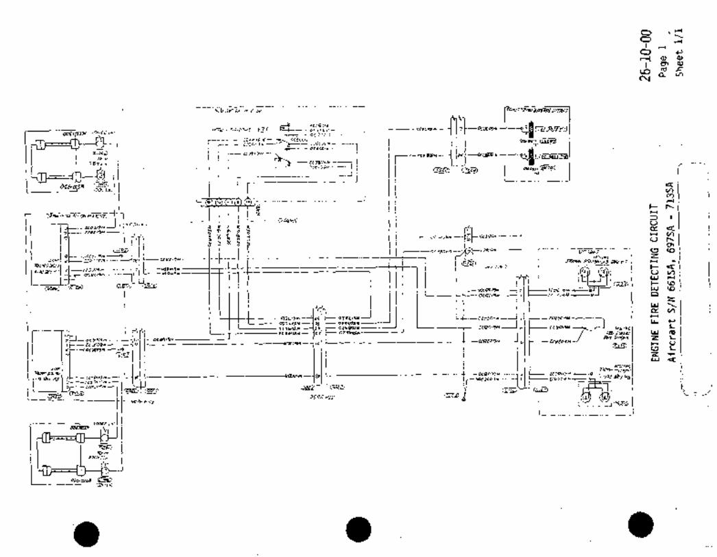
O´•T’o
O c,
I-l cu cu´•a,
cD rcr´•r:av,
N
r Br w r"~ezld
r(bc~ OZgtLld 7(WEc‘ SN)
~s,
1 ---h mohm
I;ZnLSW
UIL_ _ Oi~3Uld
i- aasos~u´•3W/ljljZZ~IOM---- i-o~rarm
W
Os~ L ii
w~ncl
t
4I 1 ;Dcv~ilnl rn
Cr,
c \1(C
%v,:a x;----I
i-I/IDn´•u~n
u
rnn/s~u
t K B or ~v‘W 0~3/0w-- ----1 H L/)
i a a 8 n ncsn T‘- onoars co
-I oho\
b:~sn-----9 Zcrbr/s/u- ,´•IM 7;DN1X j~rJ X7 j H 9
~AYlnD3 (p~7:-i4) r7i~- ~I I
L;J LI,1------eC-t-t+-----------7~ ill II I :.I ;uru c~ul I
Lc L(DE;)r W IO
*I I--nZCIYM C~Z
Wa~v,
I~L,,m DIPL,~Y oL4dcSN I;C~
OIJL´•OSM OI D1*LO~m LL
i I II ~ai 12114 w´•
Ior~enm ol*BeSY 0(80/9M n
L
´•nH Z Iocrs/tn L CC17CO9N i’ Us E~3C09* Is
3 C~
IZ ’r
W
M~s~’X"I I I lli I III
ocspoD1 ----1 3 U3P03~ e~
scloos~u I LLDC~S 1
~iZIIJ hilS
c_~_
(au ;s~
;Iv~
!CDLIS~

ccr/7m)W~9!9-’o
Fr~x/aE
ius 3300)
~55,1, aHguiasC:rAMSo I
ee~s N6o?azz
soo~sn 60~12 ~ZOF14EIE-R~NPE hr-
*codcnY~rr
!YY/7W
9-- wsow)~---le
~m CS~D I,, U60XR ,r.
Zo wio
G)
lv6/0870
H161UPO1 (511 LYLI?CIO
m kl6oclalo
3,-rlu
W6~3CII nyl~X)
im W6,3E)7 ~Tn
_I.,n W6/7A~Om1
CPM~Lm 7an FJy~TO S~rrH--I s~aaL/o
B1mNRIIIt)
~vusanO I*Y/NGH 596gZ~ t-
;OOC ~tH r
ln~1,7W)-I
cs~w
~s’ fffF Df~
IWIIBC1 B nbraga-fi~i- ~L’70ZI
wJo~3a
V1L1P82~ -------)-Y~L((CIO 7 wo,ozl’’RE
L~Ilou~M
_Larr (vsz~m,
L_ Mig
v, -J3 P,IDcP(D (P
ct Or~
OO
r

CHAPTER
FLIGHT
CONTROLS

T[-~h iMicSu
rLL~--- Cwlal I
2~---------- cwzo/ --------.L~
Plte Su.cwloz--------~3
tW103 twZa3’
CWIOQ ----8----GWSOQ b clya oa: c w z o a
~zau cw/os ~------CWZOS I~sOL---- CW 40
cwiob cwzobNAP //fi~T I ~e .us~ir
I
GO AROUN~ SW CWI O 7M
cwzoa GO AROUND SW
cwloa ------´•---(3
p_ I acwlll --_--IQ
L----C~VIIZ ----------~5
6 cw211
7t-----~-cwz12 i] I/p BISL SW
~-ew I 09 8TR/M D/Sf SW
Or‘jt-o_CW I O -----------f~9r---- C #~O 4 --o, j TRIM else sW’PTCW2/o --d I
TRIMSWvV113 GWZ13
vtWIIQ CW2/4 ---Ld TRIM SW
CW/.IS cw 2/5 h
u~S HI YEAT SW.~LH)
I
syNcHsVI 9 ocwllbOc´•uqlTcHI Cw.1/9 C1V2/B -o
orj swICW2/9
PILOT C6NT. WHEEL___
1 COPILOT CONT WHEEL
661SA, 697SA 713SA
Q 661SA, 697SA 704SA
~055RAMD SUBSE9UENT
I-coNTRoL~cocuMk 27-00-00
Page 1Aircraft S/N 661SA, 697SA 730SA
Sheet 1!1

RH uhN(1 D\SC
Crl~lD ,e~
tto78rr
z 2
C-13~81ZI ~C226C 22
~go
ioru~vKI/CW BDX TJ? jl~n AIIERQW SLLCTO~ 1<J~tin
~-7 G~TTF)
Ac-l L;IR~R/LfRav
A-/s ---I(tg) YLtiT/DR
i,,,,, ~_ I
r’
´•~a I
uil~Uo/DToBJ~1
.sJ-2 cm7Azz
DF- I II CT~A2Z-?(f~
Be-2 Irt---Cl/dATT--~IIP*RII. 1
8-25 S GiZYtT~
criurCR IPPFSTAL CaMBr BOX
CefFD
2 4c22
---1 lloC´•c2 14" 22
__
I W(LOLDBL. 1L~
C~’AIZI
I ul9cu,r PIWELV\FT)
TRIM AILERON CONTROL
Aircraft S/N 661SA, 697SA 713SA 27-10-00
r-- Page 1
Sheet 1/2
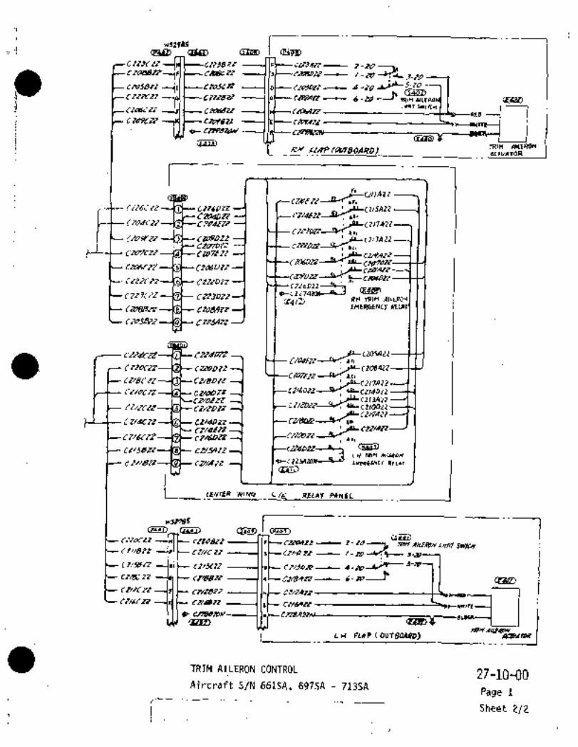
.1 rs298Z IuanlD I
Cr~rrr Ct~lB ´•7t tLUATr-e Z-ZO----´•kCZoBSI~ CbgCt( -~tD -r~L
P ClaSBT~ Ct4K1Z 5-~0
CIT~Y2I It~Z2 CRIRR 6 -~DP ~4PP
TRIM LIIU
NLdCtlLIMIT SWI)T[H I ICi~Qrr
CIOPCi~’Z C~WBn CILLPRTL
CRP8~3n/
GULP)CLcllt~ AIIERONI~ RH´• IclA;P/G~BOARD)
TRIM
~P(TVATOR
rLFI
Ccr~se It CII~DZt I~L(Z15A22tZad02~z
C2~dCt2 t-3bdflc’_
~D,---YJ~ r~7DTz
r~~LLC113A22
CTMDIZclmr2z CrO7r2r ~PLCzAAzr
CRMCz2 ~4LCII/AItn~7YDIZ--lvi
Czz~ozrC22 6022 *L_L
*I
´•0-(227~4tCW--dlr-JRH TRIM AIIU1OFI
tm88ZZ tfD(1W21
~CiZIJAtt
Ci~tdPn fLCZOSA22Ci~fll---rv; bn
ClfDC~ CtZOD12 ~LLZOgAZZtl07tir----~1Zr Lrl
CI/BCzZ Cr/Borr_~
IPLC2I7A22CZ/otn CUWlt ~PLtr14DZ2
TT/fCLIZ ti~ZDZf C2/22322---~v; ~LC210D22
t2/dCzZ CU1ID~z
rz~clz n
ru/Azi´•
Cl/5BIr CT/Ylt2 (lm~L,LW TRIM Y(C~OIJrwr;a6~Etcy
(L41L)
C1_ wlYCI R~LAT P~NEL
rp´•o7,
Cra~1
rtt08tZy mn
T2~C 22~ IsC-- rr~o r~ /-to-sre--CI/KL~’ P~ 4_iC04jq- J-
c~e,-tz --Isl c~as2r lec-ct/eRtt LS-~t´•
e~o
C.;+/lgl~ 11,I Ct/i´•At~
---(KI t-- CI~BIZ ’ILC- cL~Rtt
9~pq3L) II i c~b
1._
L.H i~LAP(OUfBOARD) AaYRmR
TRIM AICERON CONTROL 27-10-00Aircraft S/N 661SA, 697SA 713SA
Page 1
Sheet 2/2

R.H H~ING DISL
Ci~178ir
r~odnl2
C 1Z~Ba
<pzos´•69
LONN~Cl/anl BOX I ~iIfRln AILERON SCLE(TOI1 1<J30d)
&q]A~-7-----Ilh ~l;r)
-1,IC I
IEH]4-/5
I
Ie~
sr-l ----1
B~-z tZMA2Z ’r 1
:uo/ozaBF-l (s~
BF-T Immi I I i I I I
8-z5 ----1 IS~---NcVC2I
I~L4)
(Pz/a)
~sT)
~Z/dHZT
CZ/aBt~
IHLMDBEiLU. W~I1OC
I’ tUDIAZ? ICIRCUIT BRYL~R NNEL(CEN1ZFJ
TRIM AILERON CONTROL 27-10-00
~ircraft S/N 714SA 730SA Page 2
Sheet 1/2
__
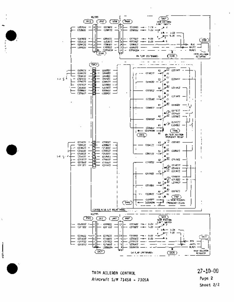
-iUSZ785 I (5407)5407
(~442) C~ C~I (PilOBJ TRIM PIILEROIIP442 5442 J4nR P408
LIMIT SWITCH
0223022 ---IHI~-- C223822 llPC C223A22 t 2-20
CZ09822 --1FI~-- C208C22 ----llS~-- C208D22 -c 1-20I gL- 3-20
5-20
C205822 E C21)~C22 O C205022 (-20 C~C222C22 G CZZZ822 6 C2ZWZZ ~-20 6
~--C209C22 --(KI~C209B22 --1IEC229Ap2n BLACK
C206t22 J C20682~ H C2D6A22 RED
C209A22 WHITE
C229B20N R
E438
i RHFLRP(OUTBO~ (L410)TR~M IIILERDN
E44D ACTUATOR
175431
F3C226C22 0226022 .F2 CZllA22
C2O4C22 C204D22 C210E22---~ F1
C209C22 C209D22 i~mC215A22i-A E2 i~-
C206C22 C206022 C214E22 E1
tZ22C22 0222022 1~03
t223C22 C223D22 02 j~t C217A22
02 j~- C213A22 iC208822 C2O8A22 C223022 ~r; D1
C205B21 C2O5A22 I~C3
C222D22 --JJ CI
83
C2010ZZ~t. CZi4UZ
iu
A2 C221A22
C209D22
C226022 --~1~b C227A20N
(EMB IX2
E446 RH TRIM AILERONEMERGENCY RELAY
F3
C220t22 --(8*-- C220DZE CZ04E22F2 C205A22C224C22 0224022
C218C22 C218D22E3
C210CZ2 ---~6)-- 0210022 E2 ~t-- C208A22
C212C22 C212D22 C2O7E22 --C Et
1-B jlC214C22 C21QDZ203
C21SC22 3 C21s022 C?17AZZ
C215822 C215A22 C216C~22
C211822 T~S CZ11~ZZ 1C3
C21ZD22C2irC t213R22
8382 I~- c219n2z
C218D22 B1I~
A3A2 ;t C221A22
C220022 1~ Al
,li´• CK~3,K407
X2
C224022
1~3 EMERGENCY RELAY
LH TRIM AILERON
(E415) .lr-- CZ25R20N
CENTER WING L/E RELAY PANEL
(5407) (P407) T( SM)ON 1S40~P441 5441 5407 P4O7
C215822 ft C215CZZ DC215022
4-20LIMIT SWITCH5-20C22OC22 0220822 F C220A22 2-20
C211822 C211C22 S C211022 1-201 3’ 3-20
C218C22 CZ1BB22 G 6-20 ~1 C~E40\C212C22 0212822 H C212A22 RED
t216C22 C216822 E C216A22 WHITE
C22882ON R C228A22Ng
BLACK
ILH FLIP (OUTBOIRD)
E437 TRIM AILERONE439 ACTUATOR
TRIM AILERON CONTROL27-10-00
Aircraft S/N 714SA 730SA Page 2
Sheet 2/2

CENTER WING WS2785
LEADING EDGE (88) LEADING EDGEI
(5255.) CP?5~ (P442) I~5255´• P255 P442 5442 5408 P409 A416
D393822 D303CZ2 C
E438
0303022 D3r,3E22 CW (or 3)
Tr D307D22 D307CZ2 O D307822 0307A22 B (or 2)
0305820N ´•0305A22 CCW (or 1)
(.E438) TRIM AILERON POSITION TRANSMITTERom R
I anr~iip lomso*nolRH FLAP (0UT80ARD)"o,
~,Zn6 ~li,P206
I L"
r’rr’5206
cum
j
BF-3 0306E22
TRIM AILERON
M214
85-3 0307922
PDSITION INDICATOR
CENTER PEDESTAL CONTROL BOX
I II
JK-2 ----11U1
I
FK-2’
3 TRIM AIL POS’
7NDADJFK-5
___ 12 j
CONNECTIONLLm LL
(azln) I5210
IUr
P210)P210
CENTER WING WS2785
=lo" LEADING EDGE (LH) LEADING EDGE
5257 P257 5407 P4O7
D302DZZ D302E22 --C CCW (or 1)D302C22.D306D220302822 0305922I
0306822 0306622 B (or 2)
0304820N n3n4A22 CW (or 3)
(EIll)E437TRIM AILERON POSITION TRANSMITTER
L LH FLAP (0UT80ARD)
iCB2033~Q LH BUS
0301A22 -7(5~ (CB210-)~0 RH BUS
C201A22(Ref) TRIM AIL
PANELCIRCUIT BREAKER
Aircraft S/N 6615A. 6975A thru 7135A
Aircraft S/N 7145A and Subsequent
TRIM ALERON POSITION INDICATION 27-10-10Aircraft S/N 661SA, 697SA -73OSA Page 1
(=------’-’--;_ sheet 1/i

r I TJrb~
d~b-- uruua/e
LSTALL 1SIK~I
OYER~O SW/rC~ CCUVSOL~
I TOZ4-~O-ZCII__
I
I I~-----u90szo -------L-~L-- ~U490AZO ----I;SL
lisi (Rzs~o~U9/Aa O dC-r;-B~ Y~1149/A20 W9~P/g
I
AUX/L/AR Y SM//sCH
jlln )I(P3/
~ii-l 1 1 4’11 W~OJA 12
99-11 Iscl WOOQAn
´•1--T
Hnl ~g I
E-SN wao~ll
I
I I IIO i
<cBtarZ)E~;b81 CW~C/A22--J
C/Rt~
VL~Z);
I ISwc~obezo
O AIRCRAFT S/N 661SA,´• 697SA THRU 713SA
0 AIRCRAFT S/N 714SA THRU 730SA 27-30-10
STALL WARNING SYSTEM Page 1
Aircraft S/N 661SA, 697SA 730SA Sheet 1/2

~ARN/N(j ~s.L/f~
~wS
~A41D ´•(Pqlb)
O~I
Q10 2ceF --9
W40qF\?2 W~313P12w4oQB22I
In wQ,oSR_-7w.rdm
wol!An w4,1Bn ~-1(4412)
~JdllA?2 Ip I wdlj812 i lrwalbC lE a
---I
(p~)
I ;B I i iZ:~n
C32~3) L
w11/6A/8 I-I j J,
I ~t
wo,a B~2: 4
wa09C2 2
STCI3caO I W410Cn ’B
wallCZZ ’C
VYP1ZCn -----(O
wdo4~27 ’R
w40lC22--tb
G~- --i
I 1wPOSSQZ2
GI~-- W42~30 f
~a88) BI f~
I~ S~N;aL
S
rlP,Critj~ o´•
pL~7
r N~tO/A1Z 49
C L~ ~wm aHAy
/c~78
O AIRCRAFT S/N 661SA, 697SA THRU 713SAr O AIRCRAFT S~N 714SA TH.RU 730SA
rSTALL WARNING SYSTEM
27-30-10Page 1
Aircraft S/N 661SA, 697SA 730SASheet 2/2
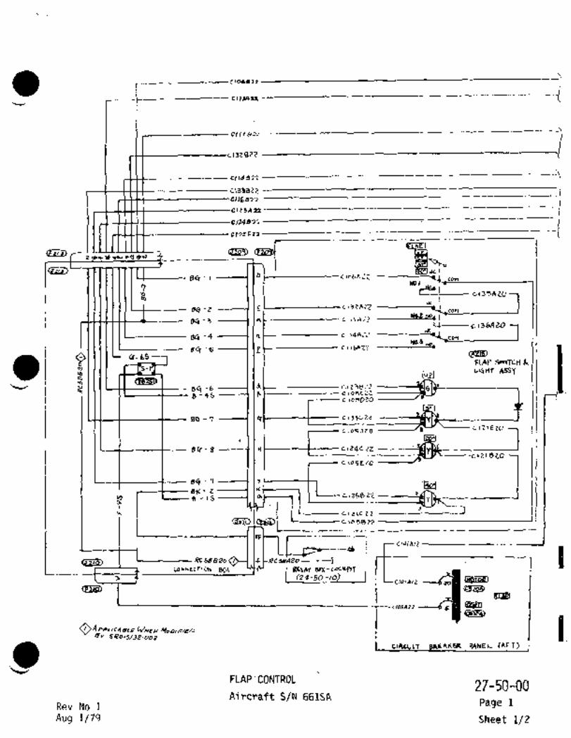
clll 8==
C13JBZi!
cIIga33
CIZSA22
C13~F21
Zc~, c~o
b clobA=Z con84.-1wo.l
s(i -Z con
84- 3 -------1 Inr~---------´•--- ct I I A Z~)(02 NO~ I
I I -cl~bAZO
84 -4 -----1 1R C1~4Ac’iJCOH
r(0.3
s4-s e c~iW2?
a 4-bS ~Ig)FLAP S~ITCY
m". L’4HT ArSY
’Lv/ 84 -b d
8-9S 8 c\ogLzZclosDZO
84 7 ------f.ltl~--t--- C 133CtZ
clo5J20~----CI7IEZO
eB s ------t ~-------t------ c 124C 22cizie20´•
c io5E20
sCI 4 ------1 17BK- 2 K
B 15 clrsar~ p
IIc e I Eic 22
c~oS8Z2
j-s=----cl,U~Le, j .L--,--. RCS8820~---I ~le58AZo--´•--
--Jclo,~lZ7
´•CONNECTION BO~ R~LAY BOX-CoCKPIT
‘M~IPHICloIAIL 20
CeZIP)
ic/OZAZZOAPPIIC481P WYE~/
Br
_
clllcUIT gMPIKER PANEL CAFr)
’i3FLAP ’CONTROL
27-50-00Aircraft S/N 661SA
Rev No 1 Page 1
Aug 1/79 Sheet 1/2

rlnHtr~ D1St
I J -40 up Un\T6 lOdb 22 1-20 ~T
(5Lll?2-10 ------------tO´•
CIP3A 22 a-2O ----------;--jC KAP UP LlnT 6w
2166 A22I-L II 5-10 ------------o´• ’UO~ 1\2
~Leuno´• (5014)tll6CZ~
C111622 C1IICZ1 FLAP 20’ 5\Jc(l’LAP1-----------d 2324 20´•
cllZePz
CIOPb22 ~I CKnn22Clt* CI1 RAP 22’ S\J
0114 B12- P~A 1 I Cloacnn Jo ov~R’LI’
olgall :_$uo~T ~r
6-10 ´•C (53
CIIGB2n Cf~L- 2-90 ------------;-~r n~P DowN unir ski
2125021 ------------iZ 3 -90 ------------L 2
Dow* LIWTy
cllhoec? _quceuow~´•C13gSZ2 7~--f-------cC132C22 FLAP I’ SI~
C117A22 -L-----~´•l I
---------~6 193~22 ---9" B~c4wj´•
c~l 71 71 RAP30 SWC106D37
IC~Be2 87
Fq\P PCILSE L#L~ SW
c(22cg~ O´•CllS~C72 FLAP O´• SW
c115B21 O~CR O´•
c(2BRE2 ---------´•r~II--4CC B~ow 2’ ~U41
CIWh22 RAP jD 5WC06h~Z
ovtK a’
c 1018/2
T 02622 I
014 622 2 Ci19C71
..rI
a,c,/ 7822 ---1 I~ C----- CI IOc) 72
C 118 831 1 I It t-- C r ~8 0 23´•8’
CIo48n ’IL FL~P RIL55ciD1LI77 n clOBd~ DPIVE C0UT20L 0
E r.i 28p
r ,acr,lell I:
(p E N u
cloSHI7
RaP T/o 6
c,o~7e, c 107C 2~ coUTOOL S~ZiLRY Pct:´•l sl? n~szz _____,;.´•4’
cn?e 21 ´•--------"ci~Cr~lON JN
g86 ii
pm I’C,i, L129
4
’Iv
n r, n
RI~´• FLOP ~ULEE;
gp a.g
e ,~onll -------------r’ P t
D~IMD6LIIYRLnY
IctoJFrz. T
C21 y 013L-----~al i"
X Cl~aR. -U~Ilgb
H3D DeLaY 6OX CDCI
FLAP CONTROL27-50-00
Aircraft SIN 661SA
Page 1
Sheet 2/2

Clllo
Clld99’2
CL9JB2;1
I
(eZL3)
clzsan
1242 ~s
C IC)-CF2Z
r gu 40
84.-1 -lIbl CIPhAZZ~B *te I
cor\
1 pp´•IC135AZO
*K.86.2
con
84-31 1,C~. I I’
ci36AZO
84 -4 ----1 IR c "4A-’i‘COH
80.3,B(T-6 e ct I Lflt2
4- bS
a FLAP Srrlft~&
~97 LLQHT ASSY
’´•v u d c.l 2382~4~ 84 -b
5 -4S ------1 (F clogczL -------iJ~LIY I ii ‘1c~o5D20
84 -1 14t---------t---- c 133(;22
clo5J20 -------J9V ~---C\71EU)
84 2 ----t I c,24C Zt
clzleZo~c co5EZO
BC7-9 f ´•i
BK-Z Y t~Jv, g -15 c I 2E;B Z’L e
0~ ‘I
I(f~ir)cIzlc,-Z
clo9eZZ
._,
---ck
CONNECTION 80~I RELAY BDX-C~Yn7 i71clruu ~PCSBOZo O J~ RcsBAZo-- ----j.
I ~29-So oj I
Icezli~
O A PPLICdgCE IJIYEA/ MODI F/eD
ti ´•~I cl~cylr BRLAHER PANEL (AFT) i
FLAP CONTROL27-50-00
Aircraft S/N 697SA 700SARev No 1 Page 2
Aug 1/79Sheet ,1/2

44 ´•rrc~a b~St I3-PO UP unrI-20-----b-rZ-2e-------------~’
Ne3ziez -17 a-Po ´•,P 442 UP Llnr~w4-20 ----------~ta"
C1~3A2z ~l’´•LO yp
ruswso´•C116CTL
cl~rsnn ---~c, er r(c~ FLAP 20’ J~’ovEll 20’cil26iz 4
0/67 622rr~- ~WIBYI’LSI
c,l 4 BR crr* CIP ----7 RlIP 5T 541C(o6cPZ j,
ClrB9i~3
:I~ __Z3;iPI I~ WY*
e-~o -----------~6 cfE~i)CIIGd37~3 2 --90- nlp oawlu unlr Ski9125422 I:?o ----------ld
2 O -PO --------------J´•
pgW1 Ll4tr
~29>c1160eZ-----------9*c ""Owr 1’
I3;1Cer F~API’ S~p(r17A22 OVEP 1’
1 c’33822I ----~---C193hZZ ------------~puc BBLOW3´•
C117* II R-AP3" SW=4)6677 ------------9 117
gye Il J
C128Ce21 ~-----clt2Be2
C:15368~ 4490 Pe~LSE Lcc(cr JW
dc~eecEZ f,224EZ --pl(C BU4~ 0´• (3i~
cIIJ87~ CllrC7i FLAP O´• 9143 t~34A22 --------------scto ovER O’
clreRf~-------------ge e~Lo* d’ ~DC134h2e RhP 30 5~OYr~ 3’
CIOIB14CldrC~O
T 096in~1---Clo4C21
c~lP 67 2 Z c1,9C72
L_1 a
-1 Irr?<p26DC1/1872 C/lql 72CIIBI)??
CID98n clW´•r Iri
clodan rr FLaP RILEI
~BIVE U)LlfPOL
"ea44CAYCrdle91 -´•----------~La E
Ip E:: NU
i´•* ~O ,.m
E
C107g?7 0
0
’1:4 all no~zzcnuzaa 4scAv p
IcIllel?r~ .R
E/O, LP 23 -------1/
g ~19o pQIIr--c~tscl? ~jlY Ij) c,
c130Rno‘
nu ruraH f P
it I 2OP\Vlie~LRYRLnY
C’""’-7 ~---rlPS012
t?l
ttr)~Tz;X
I~ 3.
H3s 4eLAY ~OX ~DC3
FLAP CONTROL27-50-00
S/N 697SA 700SA
i Page 2
i.___~
Sheet 2/2

ClilB=
~J28ei!
L13JB~i!
:C11~833
,r5n
12482j
Clc~F22
4
84 I b cloL -----cl C/oCR~ IL~B JC
NO.I C/osB~Z;
~-)-i´•135RLO24 ----I Je t- C/3 EaZ ----t----
Mn
7
BtT -Q1 ~1 c"46,2 -----e----C/l~tAaZ I
BCT-bYo.3
e c ,1 6 r32 --t_ C//L Y 7 281111´•L Cr-bs (EzI~DO FCAQ ~vlTcy
LICIHT AfSYL I~sc d84 -b R~7 I´•
8’45 F ----9--C I oSe 22
cl05yZO r
84 -7---~---1 1 Q)- c,sj~
clo5Je0 ----c/JV C~71EZO
i -r BCT 2 -------´•--t C13QCJZZ
c io5E20
st, 5 t-C/36LIZ
BK-2 --I IcC
1Le 1 I’ I I r j
f I´•i c;Z~ ICf~IZi rC/~CZZ li´•
rE---dC
I L---ac58R;zoO f 2o- ---I. -7CONrECTION BO/I
j Iz+-Jo-MJ JC/d~n
O APPLIC(ISLE i c~aJllzz ---6~’BL~BPI
Oy
J) jcrLUlr BRE~HLP PANEL CAFT)
FLAP CONTROL27-50-00
Aircraft S/N 701SA 713SARev No 1 Page 3
Aug 1/79Sheet 1/2
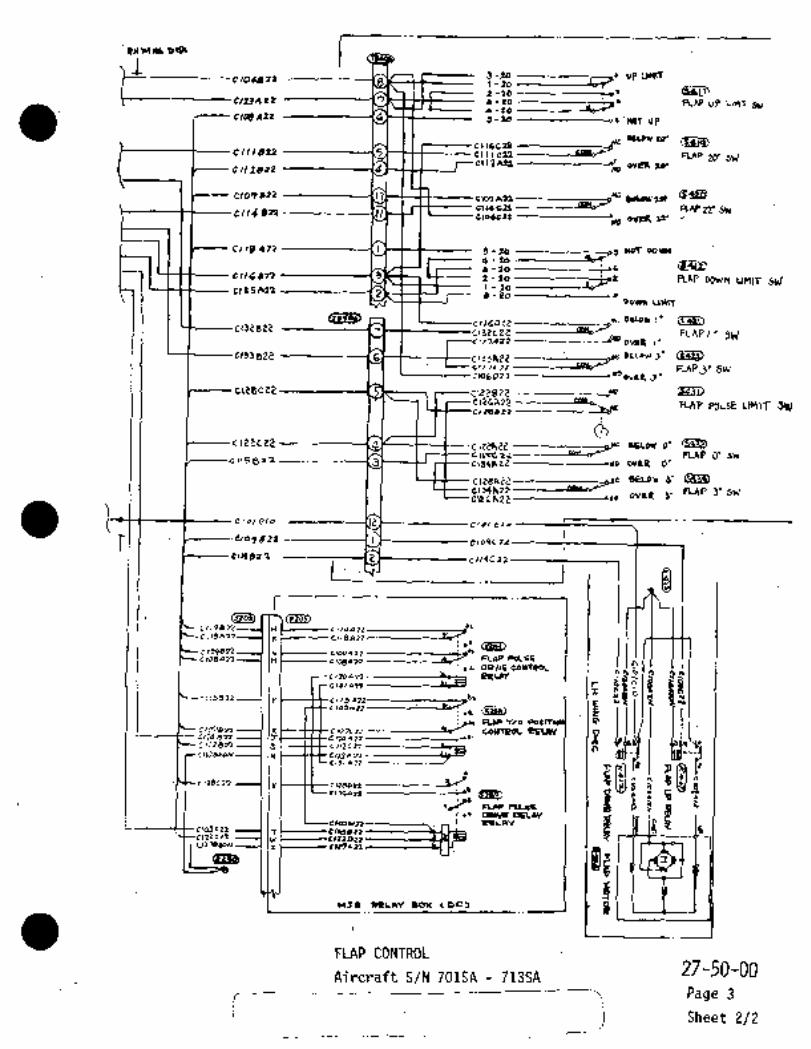
344140 olQ
Flo6dzl --------_-3 -90 up umf1-20 -------------b~2-10 (94L-?
NP3402 7 6-20 --------~--iC FLAP UP unT ~U4-20 -------fo~-
CIC~A22 -------------16 5-16 -------~´•’WOT UP
~Uswro´•CI16CT1
Cll,b22 ---14 CIIICZI FLAP 20´• 5\JEllPA91------------J oVOA 2q´•CIIZ6l2 42
C101622 -h~A0114 C22 ----,-----(iLa6 RAP 22’ SW0/14 BR ----´•--------´•III CloacPp
40 0409 21’
Cl,B 427PiA 1 -I 5 90 ----_ --91 007 2044
4-Po --------~Cr
6-130------------~s6Cllbg2n .3 2-90 ---------~-i=or nAP DO1JN UMlr S~JC125 421 1-lo ____-Lb
2 4-90 1~
22’45 ~\14rT
cllCDE~ _,wcSUo*l´•19282~
132CZC caK.FLAPI~’SkI
C117Aa3 _,,___40 OM9 I´•
cls3BZ21 -7--C133hZZ BELoW~´• ~a
Crl 74 31 RAP30 Swc~06033 ------e YO
ov%cl J
ci28c22--1
"0
c\isxeZ KAP WLsE clnlT SW1/25022 -------------a~
nc~2ece2 5Elor o’
C(1TC22---------YU~d FLAP O´• 941c 115 B11 0163 O´•
65LuW 3’
C\YCh22 RAP 3’ SWtL6R22------~d,, OvalC 3’
elolalo Cio~c,o
i L09822
01)96~2 E tllPC72
i 1I
L (J~
IC( _
,6~
re C118812------------I~C
CrOgBm croqmlzcr0t)an---( IH ,,oaa13
FLOP R1LSI
oPIYE tOUtPOL0
f KfPEUW
~D ac,tsa32~-l Ip Cr,
E r h)4)
T/o
4
1~C107BZ2a
co~srpoc 05LAY p
era~aIS ’------~----kci, 0
cr~aloEJ N IWlnE,3,12)
ly Cl~botl8i apm,30A?1
r9
FLRPClhEE f t r
p.RHR OaLny
W3´•s ~LAY 604 (OC3
3
cto~Frz. T r/050cl:Izzr?? 021
´•UZ1)6~0N X
(B~B
FLAP CONTROL27-50-00
Aircraft S/N 701SA 713SA
Page 3
j Sheet 2/2

c ~jy, ne______----------L-L-~--
CIIIB1=-------
c132BE~3
Gild 92?
L13JBZ~
rC~r5A 22 -L---~------´•l-- I
I 12Qa2s ~‘IEIT’-’F22
~u 6u
~2,b Cio6F32 ~C/obbz284-1
WD.I
"Oc 135A tO
~m *e
BG´• -t (C C/JZ~9lz
84-,0 m.
S-IP
94 -4 -----1 Ifr Cl/4C32 --t- Cj/4~2;Zcon
90.9 t
s4 6 p CIIL F32-----~---- c ,IC ~IZ
O C~Y3PAQ Y~ITCY
I) L’"HT ~WS’/
~EJ>e4 -b
d.C~- C /33C 2-2---t- C /f3 a´•72O
C I 0 ~L it---c-- C I o5C329e e-ss 0
0tn C1051)EO
ecr -1 ----i I C133CZI
6-1 ccoSJ20 3 ctzIEU?
eg3bD I,,_,
I r C C1340~2-C---c- e ,Iqe i I
CIZIBZO’1 I)c to5E2g
B(r-9---------~ljt o~jct9
BK-2 K
L-- e -15 1~ 1P C´•l ZF;A 22. p
Ut I L~--CI1IFSZ -------t--C1IIC 23 ii
(j~ L--- C10 J~mP2--c- Clo5892
d-/PO8.;ars8gzo O
t SEE’LONNECTION BOh! BOX- ICoCYPT
i (24-so-/o3~1
-Clo 5CENT
O 714SA 717SA
‘I/C/~CL//T BRh4hdn C~x7ER
I__
O 71ssA AND SUBSEQUENT
APPL/CD816 ~t/r/h´•c/ FLAP CONTROL 27-50-00 INoDI~IPD &r sRolS~Z-OoZ
Aircraft S/N 714SA 730SAPage 4
Rev No 1
Aug 1/79 Sheet 1;/2
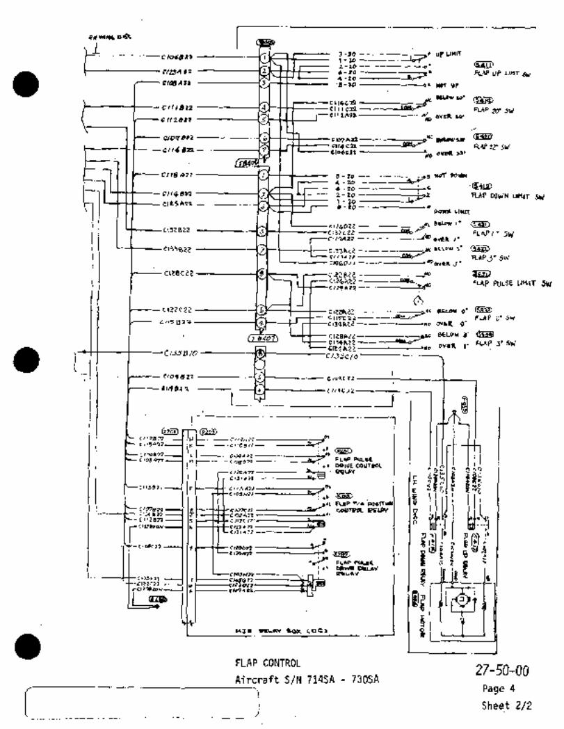
pd~wa t~rR
I3 -90 ----------;--~r UP Un\T
1 \-202-10 ,^t
e~e3402 ~2 6-PO -------------~--iC KAP UP Llnf 6~4-20 -----20"
GIL1~A22 .3 ’5-20 ------os ’CLOr UP
sC1svno’t116C2I
CIIIL)2P -----7 4 CIIIC22 FLAP 20’ 511’cllPA~-------------r’ ,V~ to.
cil2822 --\d 42
CIOPb22 ------16
C114C22 I-----""d RAP 22’ Sir’cllC 622 -------------17 closcnP~o OVbR 22’
CI,8 422 3-94 ~-93 wm 21744
4-Poa-Po -----------~s6
~1 2-90 ----------~or nAP DO\r/N unlr skicIesA21
-16J 3 -PO -----------r~
D4WI( Llllrr
~116022 ~1)132822 -~------rJ 132CeE FLAP I´•SW
rl?A22 ------~--44 OVEt
2133 BP~1 --------I~YC Bl~ou, 3´• ~3
Crl 7A 71 RAP3" SW---------~s wo
gv 2 R i
c~28c22. Uo
---------4pa,_ FL~P PCILSE LMIT SW
clzse22
1-78UO6 O´•
CI(FC72------´•----Y~--d FLAP O’ SrJL115872 ~4 c134RiZZ----------s*o 21163 O’
8486LOW3’ L~UQ)
C134h22--------P8bd FLAP 39 5111cLsAZ~--------d*o OV2* 3~
1CN~D /o C/JSC/o
Oogg2i
oNp 82 2 6 tllPC22
C ir
,1i
n
cJzo~C,17872 II~ C114P 72---------;rJ
(I( C r~ 88 22 -------------4~8’
Cr09821 c~ogszz------ _,C~rncto8an 11 ,,ga~n .--a~r FLOP PULIE
DOLVE COUTPQL
r nI(1, rI 392!~EU\Y
E:’u o011~Ip
~o ,,m 6 kl-CIO~C11
c n~ 4 22lo7c?r caUTPOC 1tiUW P
ncrr2ern c I,2e 6trljezo~ Fl
r,01L\?7
Q,o´•(Y- c~tac;? .(y c,zson -----------C! 5 ii
*~r’´• ELar CIC´•E8 f i:
MfO OeCAY a~x
coc~i aI IctMan
Z1CIOJELL. T CloSOrZ
IZ1C11 y OIZ2?dac~N
X
15
FLAP CONTROL27-50-00
Aircraft S/N 714SA 730SAPage 4
Sheet 2/2

CHAPTER
FUEL
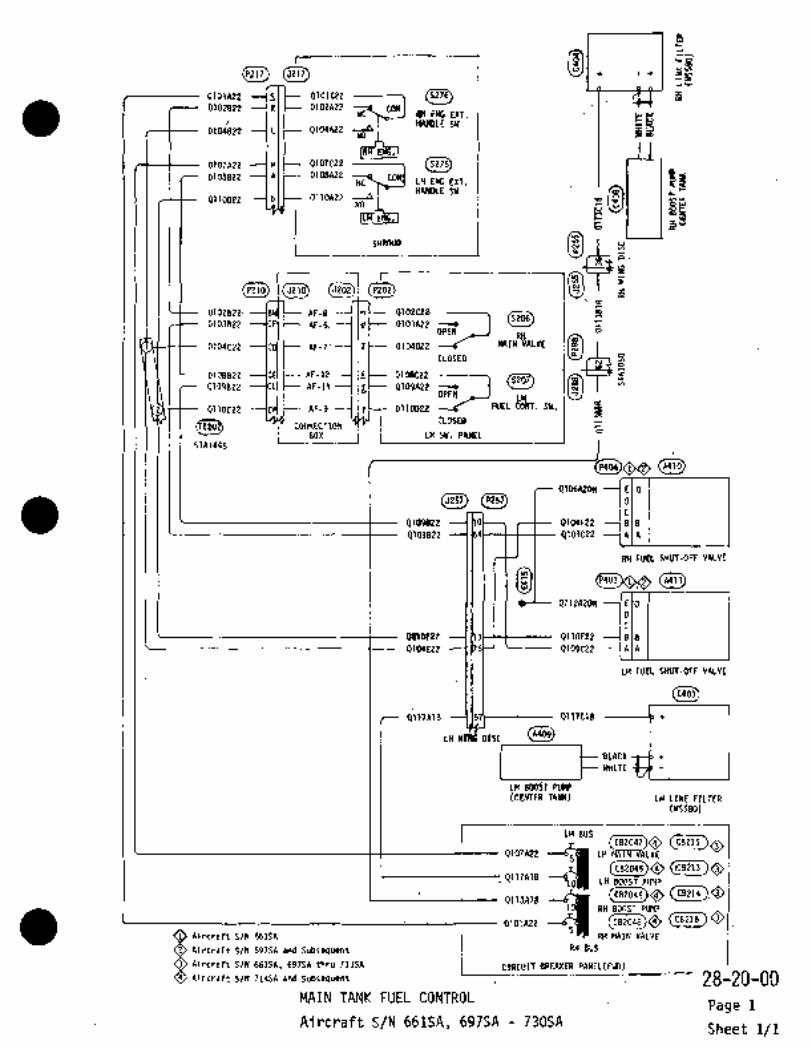
1 81
p104822 L p1041\22 hi
f I9101422 c 9101022
4102822 91021\22 COMI ENG EXT.
i HANDLE SW
XI~(3278)0107A22 MIC-- 0107922
9108822 ---la(~- 91081\22LH EXT.HANDLESW~,g0110822 -~blt-- I)llOAZ7 --9
NO
i SHROUD ti x
r
P210 5210 5202 i~ON
PZ02 IV P:
plOZBZPI Rf-8 b182tls9103822 AF-6, d 0103A22
rJPEN
1 n104C22 AF-7 2 0104022
CLOSED W
-q108822 AF-12 s 0108C22
0109822 1CL(I AF-llllbl 9109A22OPn
FUEL SY.
i=I
2 011OC22 AF-9 C 9110022cLoKOi
CONNECTION 61 j LH SW. PANEL
STA1445
WW
Q106A20N E D
(P2y~ I ID
9109822 rt-- Q104F22 ---lale9103822 4103C22 ----IAIA
RH FUEL SHUT-OFF VALVE
~I (A411)A411
´•QIIZA20N EID
Obaree ´•--1(13H--t------ 9110F22 --~Ble0104E22 ---1)75~-’ Q109C22 --~A
LH FUEt SHUT-OFF VALVE
(cson
1.157~--------- p117C18 --------b´•+
LH YA$ DISC
gLACK
´•WHITE
’LH 8O0Sf PIBIP(tEMER TANK) LH LTNE FILTER
(usss0)
I "LHBUS1 ~2 (ceeooi)~ Cceils)OCB215
9117A18
9107A22 LH MRINVALY~
~oLH BOOST PIIMP
QIIJA)BO iC82046 CB214
P101A22
RH BOOST PUMR(CB2048)~ (CB216CB216
Aircraft S/N 697SA and Subsequent RH BUSRH MAIN VALVEAircraft S/N 661SA
Aircraft S/N 661SA, 697SA thru 713SA I tIRtVI~ER PANEL(FWD)tIRtVIT BREAKER PANEL(FWD)Aircraft S/N 714SA and Subsequent 28-20-0[)
MAIN TANK FUEL CONTROLPage 1
Aircraft S/N 661SA, 697SA 730SASheet 1/1

nr~D j~n
--orozezP--h;rl t- AT-5X cSzc~zAtZ
R-5P $SolCZbFI(-3
j BZZ19i?P----P .e TALITOJ
FlzlBz~ p3n,pzo
-~olzazz--lsJ/ ~--AJ-q MIZAZ2
--43028 i-- -4J´•b 8 ´•4H ~IEL
sN
"6p t- 7n 11 I AF-(O-I (b 9~1)9ZZ -*o Q~DA-re 3 (920(cL7 C~
/t~Bllo~f3 rsr~fnuTo
33-15 Ik" ’L1 OL’3P~2.
nF-23--I WE"
LH c~-UL=Z
5W
PaI.~
~BED ~olII I 3904(
iN-4 ’33"..EK-4 n 1-03~9E2
E-IN 13 Our~PuMp TE~T-
I- ~aJ_sw_
eK-~´•----( (~5 C
(eoDI(-bp
:.´•4. I~ij´•lcrpim~ i~I- .i’339eK-484’3 .Ovr~
Pr)MPAr-la --I IBD~------021) B22 I N~J IW_AF-ca 6213522F-OP ----OZOtAU39-32
339-4r-IP
r- CULLI
q301AZO ~caa_as)
pc4 6*tO ~P 1 IL~ cP~nl)t 32 q/L) 20
IRESOAPO
T´•lt
I0
_1x.
i,
INdblF~O
gy JR 0/5/32-002
See Cockpit Relay Rox Circui~s (24-50-00) 28-20-10
FUEL TRANSFER CONTROL’ PagelRev No 2
S~eet 1/4Aircraft S/N 661SA, 697SA 713SAAug 1/80

(JPS~)´•J155 pZ5~ 022234
qelee~2 1(14 C-- g2re Ce 2 --t-- 0212 020
9 hozs 22 qt6ZC22
’Obots~O 930~6 ---~2;1::9303Bi?d I 0303~E20 OLOE2P
.-_F--Q2/9A20~il
~A440)A440
C´•P434)SHclTp~ic VALyE
pqgq RCIfIP
(wS~I/Lso L~P)
rrZfk20~
63P ~CZo i 1 1-9202Pe2 ~R7;07)CR404
’83/191b’93026´•20´• g2l9A2D
Qg~ ceo LH OU~IP Qzoz F-eo
0( r4ZO
ca465
0209820
´•i__
o~PA~ei .qt´•IIFE
eR´•´•L)
s309C20 Ru
our~aEUCLIMPC*C
63l i B 20
0’slreU,~3/1;Aao--l:Lw Or)tdP
01 r~ p.rrlnne gL arDAIR S~UTOlrP
IA~TRC)AneAII P4EIipL YArv~I
i 1n2sAzd 24 0-Pd 407;2 o-c-FrrsAZo
h22A8o~- 244-20
305820 OJCI~C120 FTZ~A 200´•0 2 I r 022 --1 1 7 Q 2 1 I E z 2
oz /3 822--1 1/4 1- O 2/3C 22
~304Beo ’I~OC-- i3304C2i, ----I M ´•I L~L-Q ii ~20 C4ab~
p 3c~ 0 20 0222420(P~57) Uo3257 P257
O´•´•2lrE´•Zb
O 2’13020
Qe/3C22 sl I Lr--~---’
92/1~92 A
´•-IJ~---- 02/54 20~ P LH:;r/p 7AA/X
bllUrO~F
e133
O A I´•ecR*rr S~´• b6/SA .O A PPL ICIQBL0WWaillMODIC/dD 28-20-10 Igy ´•Si4d~5/kP-002
O AtRC~PdTTS/N 697SA~ 7-~RU 7i3SA
FUEL TRANSFER CONTROL Page 1
’Rev No 2
Augl/80 Aircraft S/N.´•661SA,697SA 713SASheet 2/4

I~SEE BLOW-UP FICHE NO. AMUG353 ITEM N
LhAD/NCnr---
9 2~ 2 D 20
0303eP6Q1~4 AZO
ni9alo O
ptatcrzt4Xo,s~7-nl as
rB26t1Zo BozC
i, RI
C1 m yl
gZ_fr--cPZ~9AZo FrJ*ls
020 CYCL OON/
r ~pefrU Z ~dNYTR6Lj~
iF~ZMZD
Al
_--LX1
I
7-;; dC"~)01’C.z0+3
’IgSd
~U OVT~R Ik404)v pu~P sesr
f 0 CONt-NON PQCOy Ip A/
LI I
W
L~r uu~n ON~L (V
X_1: 4 st i~x~FTE4PIO
XIZ i Orolclra~20rt20
~PloX 4..~f;U LU O~rti(
Al OPur~P Tar´•T 4-no~N
9203422 ri~b)CEr;F~
4~oz KZO
uTIPF()ECi
9~1S420
i92, IK LO
,O~11 UZZ
rgzzs~eor
O BZ)IG2O
i,,,,,k.
qzzzA;’’ oz~aa 3
)c6rti~eurl9tllfza 0221*20
0 92131)29
qvl ~O
Fr331 hqr
:3’
CS214AB~--12
~OLl t01u7
BE
r I´•6’43
P,
QY1JSto
qZO~Ll)tZ
~j Oqe 39
~APPLIcASLE FUEL TRANSFER CONTROL 28-20:10By SOols/3iLoo2
Page 1Re.v No 1 Aircraft S/N 661SA, 697SA 713SA
Sheet 3/4

Qr~DmJ
--Q30S r
iP Sv/lt~H (iY~tPOO)Z Q@3B3T
---~-I
c~a--6~Ma;WY1-eP Wllb
c~su,,,,--"le
c;3 c~ LEyeL SIG! IIQ~f/Pk9NK i
K~271XT ~PD
QF~PD (cJm,
~-Otodezzl (I ~II) ~E?gp PWlpMLgp)
~t~w I
rrvrr s~rf
FIJEL TRANSFER CONTROL 28-20-10Aircraft S/N 661SA, 697SA 713SA
i
Page 1
Sheet 4/4

G~ @L~in
k~)--4raBL20u-´• -----I ~uF-- PtdBezoAJ-’5*J-~
~azo I e;s;r,
Ir-~fL
u´•i
I I tA4o
Pctcaro----´•kc(~- Jr-~
Cr-rg1 I 8205110
rr-9~F03 1 4261826
IQL(I)ID EIC´•L
--´•---ly~’ C~-J
g19A~O -.´•--CYI~
AI.Q M~-dt67920 -0
jjL ~---1 i~A 26 ---5
,r
i.. ´•I´•~’-"’ I 1 11111 1111’1i.. 0*-4 -I
iC-1N. 025(420 -5
i p~-, (tt- Qi)4QAZO --´•I
ca~ cEt~
Dl)a~C Iaru8cmu22u
----1 C
~r-a -----1 lw~--8207820--lF´•10 Cn~-0206820-00-0 -----I lo~--q247C 20
8242020
DPOZEZo-c----~r
AF- OqPoza20------S
O Applicable toAlrcraft F-)31 420/lPO-----~J
O Applicable to Ale~rurco
ft S/N 721SA thru´•730SA:
-9~ ~pF----, pi4~opo I
_I’
FUEL TRANSFER CONTROL 28-20 10
Aug 1/80Rev No 2 Aircraft S/N 714SA 73DSA Page 2
Sheet 1/4

r~ ~Zlty I I c~DI ~sr,
-j I I I c~aacls It, 4lseam---------´•--------- 8248420 --II cloaslo~ I´•cr~-- 03(MC´•´•0
OVTI* owen, ----I 171-- 0106C~O
0vnP5y 01,11120 ----1ld2~10 1416m
I I I rozem~p
OYT14 1´• I III(DunP~H,
III 1 ´•11111;QLOCEZO
~e43024320toreztm" i
-te~
o
cc~m,
FILOA~D rOIl~d ~tO
Larnu~ oloarlof~LOB 40nlE~o
qzovaio 0206cZo----Sw il´• II o2o8e 20
(YIMIO (R´•J) qzo8e 20
0292 820
40 C;EaiE)IIII I L-----qZ1ZC20------(
rra~
I Le~eJ 0za0Bzo
n36BZO Q
m/R~oaz07A20;
L 0203424Lcwwt rW6 (61~ OtllEZO
q,irc2o~i> QD qzc0feo
PCINELol~JltoN--4P,4111C0207020 ---J
6101620 $24rSZO ---5
078144()u( 06 nrCINet~RQF 14113
rr (vrOe BIWLI, qiaSCZO ---j~oAmI ~Y 6416 UIWT
CU448~0cagcaeaas
5-------~---- 0166410 i c.wOmO US~LL+IL 4101120 ~´•--1I:
aJ w~4u lleIIl
OLM
CINWR 060604617 AsrrLr TI
CruPzartBI-?O 406-PO--tFTZSAZo?
0111610I -ot,lbl0
487~n:
IC~C2O
01’lc20I 1 874X~O -----1
0101410 914,610
BZOIDtO----1 IsP~--BZOIEtO
I1I
a
10 j I~w rl~N1P1QID2O
c- b~a
Olo? j IRI rYTL ROURA COWII
QQ~OZ4za OApplicable to Aircraft S/N 714SA thru 720SPIA29 wuwoOu
6~ OApp~icable to Aircraft S/N 721SA thru 730SA
L. OAppl icable to Aircraft S/N 714SA thru 730SA
jWhen Modified’By SR017/28-00f ~sBOiY/rB-Oo2
024,1160
I oeo-i~r~U49
Cl2n//I crwC1 tcwni: 1PPOZD20 g)PP,rDZDO ´•28-2d-10
FULL ´•TRANSFER CONTROLPage 2
Rev No 2
Aug 1/80Aircraft S/N~14SA 730SA
Sheet 2/4
i

~D ~D
q14Bs2o o~dalo 914B9Zoo~asslo 4lasclo 02 ube 20O)JdRIO
I,bblO --(Ti I 4)16C1~
Qtl6etc, ---5
OZ~bl\Zo
BzoZEio~ (5212620
0252A20
9eo6EZo a228ezoI´•uI_If
iiLBI
920d01
loiiEo‘ al,oa 20OPZ
d0´•Ari~P, 423ZA10
i214
~OI ~r-Fre9/1Lo
~ilD t~ir)2~.DeEIll 1~3~LjllbLadl 1164 to
?D 0( rp FUEL LEVEL I)EU~
WrcbCro 0iolozo 1)206 070A2o 7 TT(~ 1 I 1’ 0254 420
0209920 6220AZo0208020 o,080l0 rlll -II 02144 20
4142020 ol4zczoI ..1 I I II 0042020
ozabn lo gzsCa 20
t)ZpSA2oQLltC ZO
4 2 2bP ZoOUtPtO O1Jo420
9t38BZO OI~BA2D 001?FZO--I Q?M´•E20
91,/000 OPoS~lo
q211~loQZ~,cao 01002076 O237A2002090 20 Y;Y II
paOSDIOI i I r OZZSA 20~1
014sn 92454 26424)520 9~41C10--+---- 1’LI I -L I 8241120F’~2"ZO´•dD I I r 0119110----J I r,
92234 20
Qli942aOr~Jlto 029~A8b----
4 205C 26 41Pr02o 1 I 1 9 20b PZoP291 a eo
P2114e~ a~/ll)eb se?7n
i9’ -’1IIII 41
qp~Jcpo0 j~bL g 2 Z~ A 200 Q 119/1 ~D At
I-t- 9ZblPZo PZ61PZO 0 ~o)G2O11 u
--------I I I
OlIotEa aw Cr,ll 9 0115410
LH LEYK RUIT L re OYTL’12 PllnC jnrr~v
I
~LILIU I UP~U
O~JdlO ----1*
-.wr,o _9215CeD---3-QINC)d
OI~UBm esacz0ol4lex, L-(I
___ 9rsJe eoJ_--4Zu7DZo ------~---------P147610 P2d7a~O ---Q247411
OApplicable to Aircraft S/N 714SA~thru 720SA
OApp!lcable to Aircraft S/N 721SA thru 730SA
OApp licable to Aircraft S/N 714SA-thru 730SA´•When ´•Modif~ed By SR017/28-001
;7FuEL TRANSFER COFITROL 28-20-10
Rev No I Aircraft S/N 714SA 730SA Page 2
Aus 1/79 Sheet 3/4

~aq)
QII~oo
I_
1arrr e~L RI~L 1 I "1 .7I:i i i I or.ar~o
r’
flIo1 1 I a* II. rAWI FUIL JY LT~L ~l*lfC1
Oto ’LOL11010 --t;T~-dUrl
4* 01~1PH nP UH~
5-- Oz~b C20 I I
II~--OefPRIO T 1 .~´•.44
U
Ot~ddmI ´•s~
´•II --tdJ
cnqszo
~PW
OrobD20 1 1111 III(II8244 a 20
CJZZqaco~u+nza
924ZClo8 2464168224418
I‘-
82274 Poetzsa 20dO 246 A ~o824/C eoO2lJA2o82I4A 2002344 20
4 Pob D Po
9 2JI L\ 20
_-7~JaH,
´•s~ ~---t":~R/-U
Zo~oM
Im
I ,J
(1~17)
iv RL~L COII~ PE:l)r
92~5C20
I :r. apslrcaars
0119Deo~iB(AC* w ana rw RM
~L* ovm m)
r´•´•I
rr~iii> ol’Jrq
Ir DUTU r*u HICL
i II 1 I I ppplrcsa~ac i tc4117dh)llI I I I p* ouru Irr) I
L_ iL C*~PU** I
Otq?Rra
P1(SL(D O Applicable to Aircraft S/N 714SA thru 720SA
O Applicable to Aircraft S/N 721SA thru 730SA(runoo cost)
O*y~
28-20-10FUEL TRANSFER CONTROL
Aircraft S/N 714SA 730SA Page 2
Sheet 4/4

8Z~fXI
j (6 81P2D5
A2~T- K256A20
~t]A3 K230
E255A22 E255822 X2
I EXT. POWERE251C22 E251D22´• fOURCE COM.
E252822 E25ZA22 RELAY
FUEL LOll LEVEL RELAY
MJB RELAY BOX (00)
E208D
E204D20
J E208D I
D EZ04D20
K P223
S E215A22 E215A22 ~AP EZ13AZ2 E213A22 ~BR E214/\22 E214A22 ~C
E219A22 EZ19A22 ~DX E220A22 E220A22 Eb E225AZZ EZ25A22 ~F
.la E224A22 E224AEZ ---IH iT E216A22 E216A22 --IJU E217A22 E217A22 --IKY E221A22 E221AZ2 LZ E223A22 TIP TANK
E223A22 ML E210AZ2 FUEL PTY
E210A22 N INDICATORN E212A22 E212A22 PM E211A22 EP11AZP R
I(,,,J, FUEL PTY IND TEST(8210) I~
H E207A22 E2D7A22 TIPEF-3 P E207822
h 5253E231
V E218A22 E2181\22 EF-4 ----1i9 E218B22
B E202A22 E202A’22 F-IN E-2N ---llrCt-- E231820MAIN
A E201CZ2’ TEST
E228A22 SWITCH
C EZ03D20 E227822
F-19SE229A22E227A22
F (M?O5)
E E205D
F C
MZO5P216
TIP TANK FUEL E201C22J
OTY AMPLIFIER E228AZ2 H
E2O1A22 F-75 E-2S E201B22 A
E226C2D EF-5 E2260ZO B INTANK:I FUELLOW(~ FUEL R’TYI LEVEL .II~ E222A22 E222A22 F-5S E-3S E222822 INDI
E233D6-55
ANNUNCIATOR PANEL P224
(L.H. SIDE PANEL) f-61 II lil ~UEL LOW LEVEL
FUEL LOW LEVELE253822 EF-6 ---t 1Z~f E253t22 TEST SWITCH
TEST 5215EZ55A22 T E-4S -------IIS E254A22
CENTER INST. PANEL
EZ3O ---C~. EZ33C
E201A22´•~VEL-PTY IND
(9288) j C/8PANELAFT
E253822
E252822 E252CZ2
E226C20
E203D2O
E2O5D
(5251) i LH LOAD BUS
E251C22 E251B22 (YC FUELLOW i i28-40-00c/B PANEL( LEVEL WARN
FUEL PUANTITY INDICATIDN Page 1
Aircraft-.S/N 661SA, 697SA 713SASheet 1/2

5405
LEADING EDGE
r W.S. 2785
1 b- E204F20 E204820 ISt E204EZOA454
I ITLNK
L_I~-O-- LZOBE L20BB E208CUNIT
P422 P497 P498P431
TIP TANK (R.H.) (541~5406 5416
CENTER WINGL/E A.H.
5293
i (2490)EZOBD ~tf-.E208CE204GZO E204C20
II´• I
CENTER WINd L/E 1 ~LO. 1 TANK (R.H.)
~Siiiij)~1
P255
A4565288 (5255)).’~ I
TANK UNIT
CEILINGSTA. 3050
REU\Y PANEL
(P435)EZ04C2O
E204E20
3
LEVEL SWITCH
W.S. 580 -1-S406 uJ
FUEL LOW R.H.
E253A22 --7 49 ~o
x
E252D22 ---7
A458
EZ03E20
(CENTER TANK)TANK UNITP459E203C20E226E20EZ26BPO S 4
m
N
w
CENTER WING L/ERELAYPANEL I I I I I I W.S. 580 --/-I--CENTER UING
L.H.
L/H~L/E I I I I I I4 m
N
E2S3A22
TANKUNITR457
hi w
E252C22 E252D22x
E253522
EZZ6CZO EP26820E2O3D20 E2O3C2O
Na. 1 rANK (L.H.)5292
(P292) (li486)P292 P485 P463
E233C --ol-a73-e- E2335 L.H. FRONT SPARW.S. 1550 4 m
E205D-~-CLlj)9- E201C EP481
PZ91 P488 w
P483
E2ZhE2O
E2338
(3404) (P482)
J414P426 P420 P492 P495 P496
(A455) I E205E E2058 E205CA455
I ITRIIY
Lg_ ELo3~ZO --a7~- IZ01BZO ~20jr20UNIT
(p432) ~I (P441)P432 5441 P441
28-40-005403L.H. TIP TANK
FUEC QUANTITY INDICATION Page 1
Aircraft S/N 661SA, 697SA 713SA :Sheet 2/2

i as
2os
A2 ~-,;i A1
K256A22X2i n,
E251C22 E251D22 RECP CONT
E255A22 EZ55BZ2--~EXT PUR
E252822 EZSZAZZRELAY
X21
FUEL LOW LEVEL
MJB RELAY_BOX (DC)
CENTER INSTRUMENT PANEL
JK EZOBDI
P225
DC- E204020
sC 5215422 E215A22 ----1A-P
I E213A22 E213A22 --18RC E214A22 E214A22 --1C
8219422 E219A22 D
KC EZZ0A22 E220A22 E
b~-- E225A22 E225A22 --1 F
,I E224A22 E224A22 --t H
E216A22 ----(JTC-- E216A22
II~-- E217A22 E217AZ2 IKvC E221A22 E221A22 --1C TIP TANK7 E223A22 E223A22 ,M FUEL 9’TYL1 E210A22 E2~0R22 INDICATOR
NI-- E212A22 E212A22 -1PM~-- E211bi22 EZ11A22 IR
P203) FUEL O’TY INO TEST520
TIP
E207A22’ E207A22 ----(Bd t-- EF-3 \Pt-- E207822 --V
niE231
TEST-v’ E218A27 E218A22 EF-4 --------119( E21R827 -y
9 E202A22 E202A22 ----~BXI t- F-IN E-2N
E22RA22A E241A22
MRINE231820
E E205D’i iT8253E227822I: E2O3D2O
FF
EZZ7A22 E
E229AZ2 J
tIP TANK FUEL I I II II II cl-- E228A22 IHQ1TY AMPLIFIER G E201A22 C-- 58-18 EZ01R22 --t A
5226020 EF-5 E226D20 B INI FUEL~LOW IAL E222A22 E222A22 F-5S --C~f E-3S E222R22 D
INDI~LEVEL
(OSPI9)E-55 E233D
E253a22 ---(BYl~t EF-6 EF-6´• --I IZ ~t E253C22TEST(5219
ANNUNCIATOR PANEL(L.H. SIDE PANEL) FUEL LOW LEVEL
FUEL LOW LEVELTEST SWITCH
E255A22 T 5-45- S E254A22
CONNECTION BOXEZ33D E233C
E253a22
E252822 EZ5ZCZ2
E226C2O
EZ03D2O
52050I
C82037
E201R22 EZllR22 ----6~ EVIIN FUEL 9’TY 1ND
E241A22 E241AZZ--df~ 082038
1 TIP FUEL O1TY IND
E251C22 ~21 EZ5182Z082039
FUEL LOW LEVEL WARN
C/B PANEL (CEIITER)
FUEL 9UANTITYINDICATION 28-r10-00Page 2
Aircraft S/N 714SA 730SASheet 1/2

I Y52785 L/E
P923 5442
E2(14F18 -azDe 2204820 Ilt-- Ei04E20
TANKVNIT E208E 4~DrO-- 52088 22080
E268C
J40L P494 5416P431
I ICENTER WING
L/E R.H.
(5293) 1~22080 E2O8D
52~8
E204620 E204C204456
E204020
CEILING 1(5288)~ (P255)T~l(l: UNIT
P288 5255 P255 (8.8. M). -1 TANK)
STA 3050 (P435)
N 4
E204C20
E204E2O u
CENTER WING L/ERELAY PANEL
WS580
:RH
FUEL´•LOY o
LEVEL SVITCH N
E25202?:-r E253A22 o N
hi u
O IWEZ52D22
(A458)A458
TANK UNIT
(CEKIER TANK
(P45;J)T
E203E20 N 4´•
45203020 h
O N
E226E20~ I I N W
E226820
IIIIII YfSsO--CENTER WING L/E I I I I´•I I: LH
RELAY PANEL
N 4m
CENTER WING n
N
L/E L.H. ~u ,w
~I ns
E226C20 E226820TAW1 UNIT
E252C22 2252022
E253822 E253A22
2203020 E2O3C2O(L.H. NO. 1 TANK)
(5292) 1~ i (P453)5292 P486 P463
22330 52338 --7 1 .03
LZOSO -4(~8 IZD5C a
E205C
E226E20 (P483)P484 54135414(5291)
P483
Y
5291 P488w
i WS2785 L/EE2338
~6) 5404 P492 5415 P496
t~- E2O5E -~-a73-e- E2058
E203Fls ---(Ll)e EZ03B20 IL~-- Eln3EZo
(P491) 28-40-60P491
FUEt QUANTITY INDICATION I ´•Page 2
Aircraft S/N 714SA 730SA Sheet 2/2

R.H WINCT DISC.
Cnss)
.52C 22--( Irl?r _______ Wg52 82o
~4Ut) I~-- w854~wn-----1 8
R.H FUEL FILTER BTRISS
j<S~ UALVE (y151050)
wso2cz2 Ilq 8802870 A
8c
Imo r ;H BooST punp
-rl I I I 1 NEL PRESSURE SYII+C~ Y~)t2 I I I I I I
go I C22 ----1 113 C-C UBo)BZO IAZm W803AZon--~6cn (e~ ~6)
a L.H EooST PYYPSTA 3050 FUEL PRE)SURE ~CEA/JER W~j YE´•r
V,Om
ci w%srnzz
!I i
I~BOc6TIVIPRlkl JE~---W802Azi
1> ~--WSolA22~P+393
esu~rmwlr W%SIA221 )771 uulBzo-----IA
J 8E Awuunc~AToR PA#EL;Io
(LH Slff tANEL) L.H WlhlG OIX.LH F~L NLTER BrpASSm
WLVEL (85 IdSa)
IU
;U" 90(DLP
cDr+ O
r

CHAPTER
ICE AND RAIWRAW
PROTECTION

STA~JOSO
H~rl BZL´•
N~/DB tP (,oC----.----IY210.PPiL 82206 BLL-
Hzag8zT -----------I Id H 203 PZL 1-~-------
I -r 1 ..,o 3DjLL
AloZBZ2 5 HLor02;L H20LD22(Ptb’j) C~
AJb nUZ7AZ2 I~ rn r~
Az ~a;iiir9
3~ eu
xI I ~´•-u,oc2o ---1
;f t-----LU~4BZO U/OBZo~l i
r- u//e toCK~iji) dtHZobPT13 ta3c22
;3 A3/NO LTS JEST
w RELAI ~O.Z er;s)
~2 O AZ
m CKz43)
~o rrs Di~MW6J1, i xl
7
98 REU)r No.i ~T- 20r ~e cv,NO Pr-,cr~e T~ER
‘Ct~- ----I//DLZO ---1
-u/OK ZO~l 1´•´•-i- ´•´•II -I IVBZb;L)
Q\
U26A22
Co524nuu, HU25A22
uMs22 HUZ5822 U~ZZe)
u I I I II IWINGDE- 1~1 Ao I ABG U22A22 -----OB 218 22
~nu2bAZt
HuI ee2 cB7
41 r_ _,,,,,,Z~ -´•-7e
o,sr*lsvm* mLub~-L L/a/L 20 -lua4A;co CO(DltM(I CQ(pALITIRYr)
FI~--------------H1/Z/fl ~Z LL
Cf-cr~´•---y//C 70 -------9
~ZeP)/ND LT~ 78ST
ReLPI ~Jo.,LSWI ´•TC~V CONSDL_E~-20)
I
-IIj-TUoDTZ---Ylr-- Y~O CZZ
I RH 8080 81/5 O 661SAh’~oq A ~2,
w ~il Q 6975A AIIID SUBSEPUENToplN4 DE7/i~E O 661SA, 697SA 713SAIb (4
~--1O (C8264)0P
~D rp714SP~ ANO SUBSE~UENT
tlO PZZ Iloo~- s
~J cllco~T BRrAnaa PA~EL i I~-L O ~snr, Hno9BZ
O Cs,lu~
(6la EO~OII(QNsu~lcn
(OUPITIDN LmlWRm~Wrl
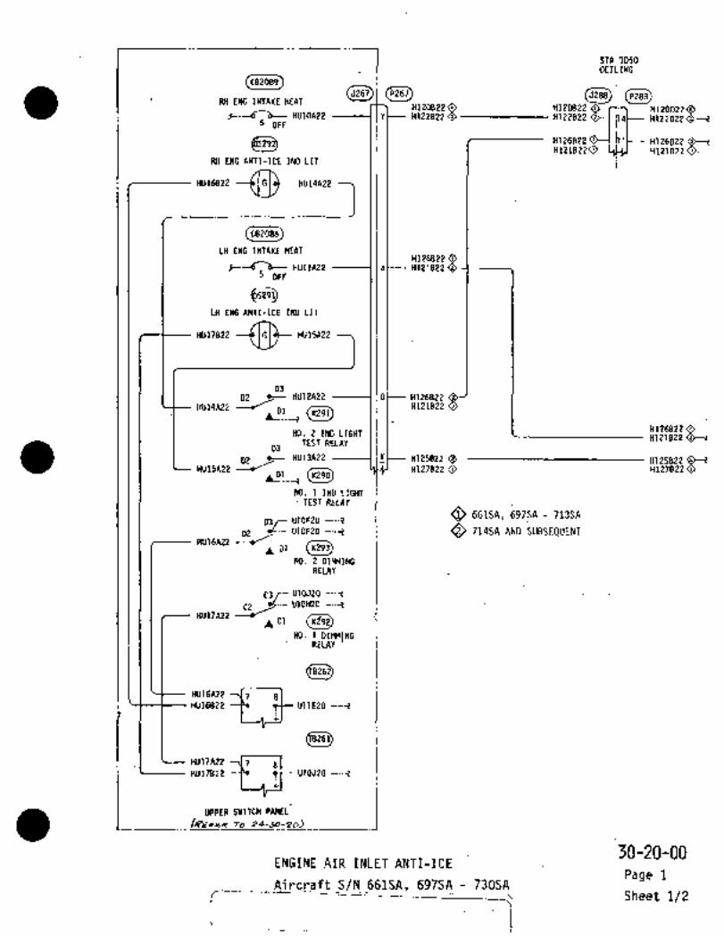
’T1 CETLINGSTA 3050
P288
CB2089
RH ENG INTAKE HEATH120822 0 H12O822 H120D220
HV1OA22 I v H122822 0 H122822 H122[3220--15 OFF
H126822 H1261)22~H1216220 H121D22 0~
RH ENG ANTI-ICE IND LIT
´•.U.
982088
LH ENG INTAKE HEATH126822 O
HUllA22 I a H121822 O5 OFF
LH ENG ANTI-ICE IND LIT
´•´•"´•22 ~D-
03
HU14A25YL_lr H12182202 HU12A22 O H126822
bl
NO. 2 IND LIGHTH126822 OH121822 0--1
TEST RELAY03
02 /C- HU13A22 -_-~ Ili~-- H125822 OHU15A22
(K290)H127822 0 H121822
NO. 1 IND LIGHTTEST RELAY
03r U10F20 ---´•~tO 661SA, 697SA 713SA
02 U10E20 O 714SA AND SUBSEQUENTHU16A22 -lr
NO. 2 DIMMINGRELAY
C3/- 010020 ---Z
02 U10H20 ----i
HU17A22 --J~ C1
NO. 1 DIMMTNGRELAY
HU16A22´• -~7 8
jHV16B22
i
011620
~8267)
HU17A22 7 8HU17822 --P1 tt-- 010020
UPPER SNITCH PANEL
i/REFER To 84-50-20)
30-20-00ENGINE AIR INLET ANTI-ICE
Page 1Aircraft SJN 661SA, 697SA 730SA
1’- Sheet 1/2

CEKTER WING
r- RH ENGINE NACELLE5255FWD. (RH)5422)1 ,-jH120022 H120C22 O ’lt>-- H124A20N 9 H31 A20 5
F- H122D22 0-1 (25~--’ H122C22 H122C22 O-("-I I a H30A20 AH120C22 O q I bC- H32A20 1 C
c- H12602201;31t-- H126A22 H126A22 O---~ JPt- Hj4A20 E
H!21022~ 4W H121A22 O H121A22 O I Ih~-- H33A20 ----I 0
ENG AIR INTAKEANTI-ICE VALVE
CENTER WING
(-‘---P40[11 LH ENGINE NACELLEP4007FWD.. (LH)
IP257 H130A20N5921t- H1218220 H121C22 O H121C22 a~-- H30A20 ----IA
H126822~ r H126C22 O H123A20N O 9 H31A20 B
H126C22 b H32A20
H125822 H125A22 HT 25422 O P H34AZO EH127822 O H127A22 O H127A22 O h H33A20 0
ENG AIR INTAKE
I RNTI-rCE YALVE
O 661SA, 697SA 713SA
O 714SA AND SUBSEQUENT.
rI
ENGINE AIR INLET ANTI-ICE ´•30-20-00Aircraft S/N 661SA, 697SA -730SA
Page 1
Sheet 2/2

___1_~r___ I---
I iO ~3 O
LH OIL tOOLER INLET 0~
I-- P190A1020OC1-1A-14oC1-li-14 OC1-1C-~4
REFER TO 24-30-00 20~ IOC2-1C-i4jM: POWER SOURCE
_ P19OA1ORH OQ-2A-14 002-15-14
L RH OIL COOiER INLET HEAT ~82687) --iO ~e I
LH OLL COOLER INLET HEAT I 0 1[rd ----P190A10 --6~----0C1-18-14 1-1C-14REFER TO 24-30-00 o Ot2-1C-14
1POWER SOURCE --P190A10RH----di~-- 0C2-1B-14
L -~--------1RH OIL COOLER INLET HEAT
(P267~ ~151,
--HUWAZ6 E 2-20 --001-26-16 281-204Q5-20 -j
REFER TO 24-50-00,OVERHEAD SWITCH CONSOLE
HuboA2a-( V Y-20 ---L OC2-2B-lb 255-26
I_~
wemREAo Slyl~cU conrsor6_
1/ ~53
O AIRCRAFT S/N 6615A. 69754 AND 6985A
O AIRCRAFT S/N 69956 THRU 7135A
O AIRCRAFT S/N 6615A. 6975A THRU 704SA
A~RCRA/FI 5/6 7055A MRU 7135A
rOIL COOLER INLET ANTI-ICE 30-20-10
Aircraft S/N 661SA, 697SA 7.13SA Page 1
Sheet lj2

OC1-1C-14 -dlLt-- :M;1-2D~14
001-26-14 OC1-2C-1614AWG
OE1-1D-16
c~C p/N INd~07 DIODE
OC2-1C-1). Lt,--- ~-20´•14F402
144;0 i OC2-2F-14 --d-E~P-- OC2-ZC-16
(1C2-1D~16
CK30)P/N IN40O7 DIODE
1-------------- 405-20 ,001-20-16
468-20 OC2-2C-16:
DD
CJ51L2)P5182 J51L2
I
iL:H~TTj //I/I ~Br-----------
E -------JCJ ~---tt-- Ot2-2E-16 Y~ 002-10-16
F OC2-1F-14n -s
A--t-(A~ltC-t-- 0C2-1E-14 Y’Y 002-20-14
B a
RH INLET
R.H. ENGINE NACELLE;~1I 1
I fI
ir"-ca---~Dc:L H. INLET
I (I I I
~c-
E-----1C 0C1-2E-16 m 001-16-16
IaA--+--I~BOC1-1E-14 Lf~ OC1-26-ll
L.H
OIL´•COOLER INLET ANTI-ICE 30-20-10
Aircraft S/N66ISA, 697SA 713SA Page 1
Sheet 2/2
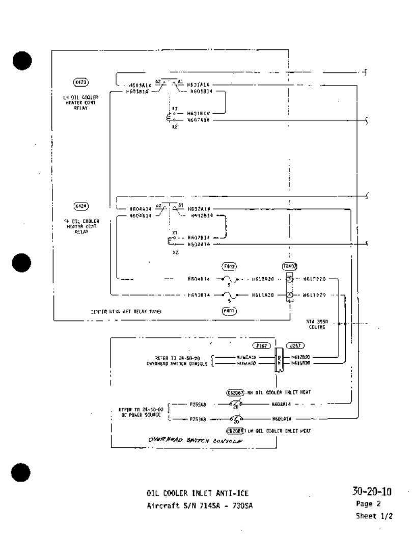
´•I
(K42~1 i H663A14!h
I
Al~.iIt~ H60iAib´•H601B14iH603Si’4!LH OIL COOLER
HEATER CONTRELAY i xll
HH6S30:8~’X2
(K424) I LHF~04p14 R2AI~Al H63?41;4H~OaBTa
RH OIL COOLER
RELAY Xli
X2
R60(414 Hb12AZO --i~3r H61.?D205 I
L_H6D3R14 ----´•/LC-- HS1IRZO n611020
CENTER WING AFT RELAY PANELi
STA 3050CELIMG
rOVERHEAD SWITCH CONSOLE r HL/LOA~D
(P267) (5267)
REFER TO 24-50-20HUblA2D
H612820
H611B2O
(082087):28 OIL COOLER INLET HEAT
I-----P253A8
20H6O1A14
REFER TO 24-30-00
DC POWER SOURCE
iovrrrHe/l~o Jw/rty
LH OIL COOLER INLET
HEAT__i
OIL COOLER INLET ANTI-ICE ’30-20-10Aircraft S/N 714SA 730SA- Page 2
Sheet 1/2

I
I ´•H603A~9.mII
H605A14R ----I IA 0 I i.
HL15A16N JD T_-I~1If------~
H607A16 B
In--------l
A435
LH ENGINE NACELLE
~1I
H604A!4. 1ICI
(E~H606A14N ----I1A’ 0 1
I 1H616A16N D F
1 Ij H6OBR1C
IA-----------J
LrRH ENGINE NACELLE
OIL COOLER’INLET ANTI-ICE ’30-20110Aircraft S/N 714SA 730SA Page 2
Sheet 2/2

RW PTrOT TURE (FSIAI~SO)
RH STATIC HEATER (FSTAZ5S0)
F302A18N --~!I
F3O1E18 OF301D18 O
,IFUI;C18 1
F3D5A18 r I h It----- F~U31A18 10~ RH PITOT STATIC
F306A18 ---lm 1 I~--- FU33A1810 LH PITOT 8 STATIC
OVERHEAD S_WITCH CONSOLE__
jLREFER TO 24-50-20 OVERHEAD SWITCH CONSOLE
r-- -iRH PITOT 8 STATIC SHUNT
c
RH PITOT 6 STATIC10AMP50MY U90A20
FU392A20F3n1818
i(5277)HEATER
8.4/´•B-?r ISELECURRENT
g-C~1237)
:Ogq~yPI
F303B18FU393A20 METER,
LH PITOT 6 STATIC SHUNT !LH PITOT 6 STATIC
iOVERHEAD AUXILIARY SWITCH PANEL (REFER TO 24-50-50)
L
F303E18 OF3O3D18
P3i14111Bn --~ill -’b CI~
:LH STATIC HEATER (FSTA2550)
1 7 ~ITi-)
LH PI‘IOT TUBE (FSTA165d)
(A212? O Aircraft S/N 661ZA. 697SA thru 713SA
O Aircraft S/N 714SA and subsequent
PITOT TUBE 8;STATIC PORT ANTI-ICE 30-30-00
Rev No 1 Aircraft S/N 661SA, 697SA 730SA Page 1
Aug 1/79 Not Modified By 59020/34-005 Sheet 1/2

RI( PliOi TUI\E (FS:A16;0)
m~I!RH SiAtIC HEATER (FSTA?550)
F302A16N ---4/)1
F301B16´•
F305A16 ~i5 RH PI;OT 8 STATIC
F306A16 1;56 LH PITOi I STATIC
I~_
OVERHFMIW!TLII CONSOLE jREFER TO 24-50-19 OVERHEAD SWITCH CONSOLE
IRH PITOT d STATIC SHUNT
RH PITOT 8 STATIC1OAMP
R253501 WO1Z(I
QFU392A2O
F301A161’1
i(5277)
~SELEtTORI
scu91a2o HEPITER
F303A16FU393A20 METER
ILRIITmllml(fHIHT L")IITLlnTIC
i OVFRHaOllll*LIRRI YTIICH
F303816
(E2r3~
F304A16N(E~16)
LH STATIC HEATER (FSTA255O)
(P279? 1 I CA~
IH PITOT TUBE (fSTA165O)
PITOT TUBE STATIC PORT ANTI-ICE 30-30-00Aircraft S/N 661SA, 697SA 730SA Page 1
Rev No 1 Modified By SR020/34-005Aug 1/79 Sheet 2/2
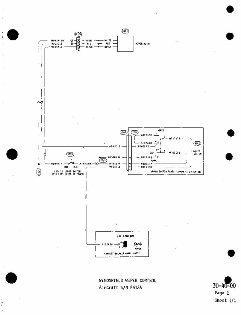
WIPER MOTOR
8101
M103A18N WHITE -t- WHITE
H1O2C18 RED -t- RED
M1O4A18 BLACK BLACK
I(J~I~ 6WIPER
CM102A18 --o
M1OZAID S25L
M1O2t18 If M1O2B18 ---I
301WIPER
’C(5242~
E212
DFF 1~LioZ-- M105C18S24P SWITCH
Hlr)6B18N q M1O6A10 ’A
11101818-jL PARK
.M105A18 M1O5B18 9 H105C18 --~------J I ICOM N.O. M101A18 ---I le~-- MI01BI8
(STA 1445 UPPER OF FW\ME)__
´•´•´•LR ~n´•
Im~rnllrllrr´•i-rr I v_c‘t-3u-1VI IPP.RY,II~ LIMIT SWITCH UPPER SWITCH PANEL (R~re ro 24-50-10)
I j
WIPERii CIRCUIT BREAKER PANEL (AFT)I
__
WINDSHIELD WIPER CONTROL 30Yd~WAircraft S/N 661SA
Page 1
Sheet i/I

~101)~Ti?i)
MiOlA18 -jt---P---- M101818 --~AWIPER
M102818 I M1OZA1B C MOTORM104B18 M1OIRIS 8
t-- 275BULKHEAD (LH)
q~-- MU1381SN MU13A18 --30
(RZ21)1 i
~2MU12818
MU12A18
WU15A18 -Ld
60
5 WIPERI-cc MU14A18 CONTROL
4n MU12818j I I SWITCH
M104818(P267)MU1´•IAIB
MU12A18
UPPER SWITCH PANEL (~rreP To Zs-50-Zo)~1L-~
__
O 697SA 713SA
1O 7r4SA AND SUBSEqUENT
Oe BVS 7
b~WrPERC82012
j P(L~I(RPTI 130-YO-00
WINDSHIELD W’IPER CONTROLPage 2
Aircraft S/N 697SA 730SASheet 1/1
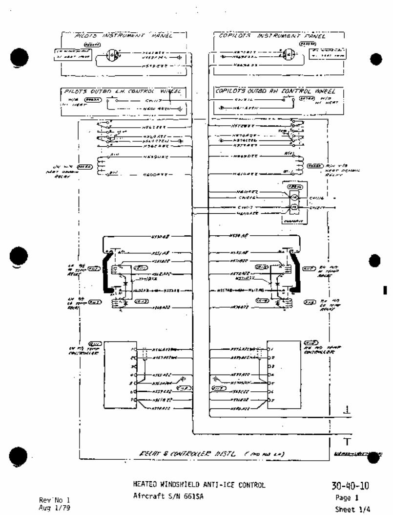
P~D7;5 COP/LdfS
~llu)Ilw plN
ia~i w´•-´•)npl6
Iw r
CI YIIOr´•´•UIY
1 I I
P/LOT~S OU;TAD L.H. CO/V~ROL YY~E%L I ICDPILO RH r01V7~ROL WH~LCOP/L 07~5-L L~Y/Jw~ (NL~a) O cwlls--------o O
L----xcaIarru--i/i~E19T
:HI I
CjSb i Ci i 1 Iu----W57i~i´•ilC t.u
II; I
Hs64 ~Le HblqRZe
H~LQCZZX/-----CIIIr
H5QIRIIr
a(r,H~90i´•Z H~LPDPZ
JH (v/S H~
~CAT Olr)Pw BI-, DEM/W~)
H600R 3~ b/oR Z Z
I‘ I E--------Hd/aaz~I
(7817-i~
cwr/b: 14 CWI/b
CW/,7
H60olA’j
jCouceu. I
rx
*´•Y/ ,’ti-+o
PY
~T 4~ I ns7/B2z_
LI 1 A8~UcnS53AB HZ17Ag-.L’- HLIZAS "III u
I I ~u´•´•p., PX
LO r~W/
i. "~"Y"" I I ~CCLPT
Iw I pX ~Hlr
CoC;~CCCR I
nn
NSUAtT j4tt I
Al~
GEL~ri´•
RPC-~ I
T
I
HEATED WINOSHIELD ANTI-ICE CONTROL 30-40 -10
Rev.No 1Aircraft S/N 661SA Page 1
Aug 7/79 Sheet 1/4
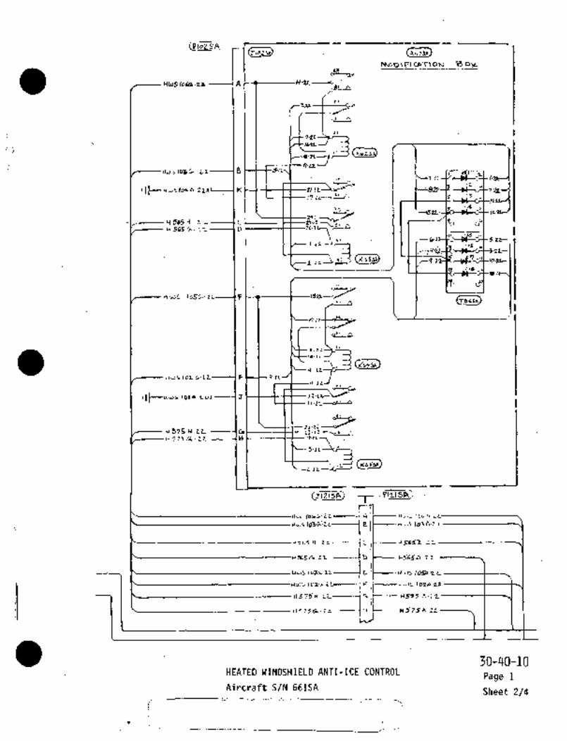
~ID1Y) (aliosa)JID1 AIIOSA
MoD\F\cRT~oN Bo)L
H1JSloCa´•nl ---i A 1
AI r~
7-21.~´•
I´•i
17-LL--J
n, I
,)t- K 2~- 1 ~137p17-2’ ’C’A 3
a
~--lru 161Y
H ´•565~-ti d’H 565 h- 2-L D Lo-1"\
,I -6,I
5-Zz--.´•1L
io
7Y12~ Ir-
i´•’e
n ws lc56- zr ,tL~ tllLJn
,a~
J-2~
II-LL
(ausn)q-L~
162 Cn´•ZL-------1 F ~--t 9´•1LIl-ZL
Il~--uws IOln-ru,lJ )L-L+
1)-2’ -L’~
2i-ZLJ 375 CI´•Lt CII
1~ 575 C ZiL --´•---(n
(r(L~Ja)
5-11
r(L~YIIr
T- \P~21 SA i
A /t--- ID6A-;L
B It----H~JS 103A´•L~
jbS H Z r -----I C t-- ct ~LSTE
u 561 b L~ -----ID /C---- U565A 2.~L
U35 (OSt. Z’L------~ E. I C--- /054 21_
jl ~-iuJS 102* L2
ZL----i r~ j~--- ~-1515 E-ft
Il ’j 75 G i.z I-Ii
575A -22
30-40-10HEATED WINDSHIELD ANTI-ICE CONTROL
Page 1
Aircraft S/N 661SASheet 2/4

nrsSRb
I~ii
MMCI’
LvmxowcvoUltr Gfi-~
i)WTrPAB
HEATEO WINOSHIELD ANTI-ICE CONTROL30-110-10Page 1
Aircraft S/N 661SASheet 3/4

r" ~9 83
HuSBsz~Hu56Pzz´•sz (i<19uHUb4A 22 ---I
I~dDSHIELD H:AT LOil R\ lhlD LS~ TEST RELAY´•N0.2
I
HUS 8/122
:LLla (Klf.’])
lND LsS DIMM,NG RELF~ ~J0.2
8’22 S-LoBt-C 578A22.
dla?z
i (WINDSHIELO n~hT LOW L~ IND LTS 7~E5T RELAJ ~o.l
y T,83_ ’1.
H11~9A2PI 1´•i~ r ~568 PZL
~Jo LTS DMNIn~ R~LAr ~al
JOAiLZi
I2 0~--HLlb2A20
IUINDSHIELD~1EATLOW
l/S IA 20 H 5SBA 1L1
H~J3 AZ0 zss;r~t-- W1~9E Lt,IWIND~YIEU) ~1EATIDW LI
:-3 111 c r~
6VL~IPHEAD SW/t~A CONSOLL~ (RCFP~
~H aVERTPV9SZRa
IIC kS93DLOIJ H183A2>575BU
rrer uL;r---p~cgD21
LH 74i I 502
565822
ssrg P~LLH Srlg PC)hl~C
u;a~
kraa~
L~cl
rX ~Y/SI ~C--C--kl
Hws/05A22
IUwS /06 n
~Ba BZOsoO------~v+S-op8
29
I´•cx n/S´•I I_ ..-"R4IP1IK´•e I
/A~1
~rrt) cP’i~)
,o~AZZAu ~lc/NCIAsoq
PAN~L wLojB~L
3WLo+B,´•
~HSWIO
-------cll´• V~7)
Z~DAB
30-40-10HEATED WINDSHIELD ANTI-ICE CONTROL
Page 1
Aircraft S/N 661SASheet 4/4
/f-‘---

if~ W/sbc?i-DH 56/ A 22 H57 /A 22
ax2
~t 55~ 8 H~ rY AS4’
b~ ~3r/AB 8Al
x~MS6Znz2 ~3 72n 22
y, rEMP ~I rt~MP
Q~,RELA-j H~tiblDZZygL1Wke
All xtl At
FIS6~AIZ<K114 )Kllq~ R´•Y W~
XI xl
H576P IF~H L~s1´•~ W~
I 1 I
r HS~ 7AZZ ~-/577A2 Z I TliMPTEMP I 3Q I I I I b3
4 rl-j---- 2 2 7~AZI --Id 4(EiiB)
5 ~D HS70/120hl 5
6 h~S;9C22 HJ~PC2P 6
i´•- t i GC---H56 4 0 22
---------t~ 22 7
579A22 HSSOA22
ce~ raH 56 2 0 2 2 H572 B 22
L~ W/S h’EAT b b RH i~S h’EA7
DEMAE/O ySL4~AZZ -------1~ 13---Hf;74A 2 ZY574C2L rJI
N
HSd2AZZ Y~72A22 T,´•,4
Act,r/5~4022 H~64DZZ B~H 6ooA ZZ Y6/ oA 22
RELAY COlr/TROLLER NvS TL
STn ,ogO-´•STA ~275
HEATED WINDSHIELD ANTI-ICE CONTROL 30-~0-10Aircraft S/N 697SA 713SA Page 2
Sheet 1/3

~557A8nss~nanl
Y RII (A I~b)
Y~PTED 4LASS
I\ W17At:
Iv ~ssSA 8
h’5~1A9\I
66R22(RED)
A P2 213UO
Lfl ~3lhlDSh’lELD
_HEATED GLASS
8hl
HS~i3n8
HI HEAi t´•1OD’ j jH57L~LZ
~ODE IND LIT
~RH) HJ69EL2CE;r/e)
r HI HEAT MODE] i_~ H1 HEAT 2
t (LH)---------ull
~Ir54 E tZ
ILH~/NSTRUMENT PANEL I
vf/s HI HEAT SW CK r" L----CWZ/bI W ,-~e
CS~7 S~Ik/S HI H-CAT II
~’6/"AL2
6~R La~
InH I (E246)
~lrrI CW217---(W~ HI HEAT SW CLtl!
IH6 O/ 111
booA ZL
Lti_ CbhlTROL WHE~Z. I (I~R/6)
´•HEBTED WINDSHIELD ANTI-ICE CONTROL 30-40-10
Aircraft S/N 697SA 713SA Page 2
Sheet 2/3

rr BS
HUbB822--~-HVSbA21LWI~DSHIELD ~ERT LOW R1 /h’D LSS TE57. R~LAY N0.2
Ilt)-1
JBAZ2,I,
/ND LrS D,rSM~’ci RELRI hlO.Z
~fDr as
S~tog 578 AztHO~q822
kNDSH16U, nfAT LOW L 1~3 LTS REUI‘J IC6.1
Hu~9A 2 ZII. ´•´•´•-I
lh~ iTs ~PELAY ~o´•l
I g --cH 56 8 A Lt
I I_ -247-zo~sgertj IWlNDSHIELD ~EAT LDi´•l R i CSz~b)
i Cr~ gctt~s IA tO --f -20-e 5 8 n tr-
A 20 ---1 25 9 -2otH r 9 tE LLIWIND~YIEU) ~lr’AT i[lCu’ L1 ~i?D
II 1 ~H559 ctz,
SLV/rC~ CO;ysOL6 (RErr~ TD 241-30-20)
´•u- 1Ir?oro~ I
(CO~u/l +O-----r
I
i~__..__ I Ii
I I
l~j,
Ipx w~- I b-----x~ABI,Fwr~e I
I i_,,,, ,,,,Ra
I
P H//y avrR T~YP CF--W30/AZE
L ´•Y/k LSVCP TH1P I~
DA/C/T~
~v r/of
v
n~OABX
N~Ir74BN----QI’ 30-40-10HEATED WINDSHIELD ANTI-ICE CONTRPL Page 2
Aircraft S/N 697SA 713SA Sheet 3/3

(Er~
H 561 A 22 H571A i~2n
If550f) 8 HS f4 8
g P’^;ca~
NS6Znzz H~ 72n ZZ r,~ c~s
yl
RrLn~ Hss,azz ~PL71~7/021
r~T´• 57A8-orr~H 61 t A 8 xzl Az
LH~ Clc~~o
YS64´•AZZ Lcu~pxl
caL~ ~_ri Lnu HS76A I~I i~H W/S
~tl w/s H4~7A2Z ~277Az2(RL Z ~EMP
Tr~MP 33
C~N T~DLLEP 22 ~3 7SA2Z- 4
~dL-, t~S6DA ZOrJ s
b~fi----h’ S;9 C 22 HS6 4C 2 2 a
FjSS4ozz HSb4DZ2
~jJ´•7/nZ? 7
578A22
t~-----H 562 8 22 H572B 22
I b RHLCI~JjS h’EnT ht-E--,’NS14 A ZZ: Hn4A22
7 jN Y 57 qC22 l\I
4-~-I----H5L;zAZ2 HS´•7zA22 -----’o-l"~Av) HS69Dz7 ´•---~Bczo-----
Hs(oAzz
RELAY S INSTL .IS Tn loso-- 57/1 1~75
HEATED WINOSHIELD ANTI-ICE CONTROL 30-40-10
Aircraft S/N 71PSA Page 3
Sheet 1/3

~/55 7A g
H5~bfl O nl
Y ~nlJo,
G~S$
I\ H~77/32
h’5~22(pIv IJsSSAB
\I ye
~56?p 2 2G’~co
h _L~ WI~JDSh’lrLD
cLnss
v
H1 ,slObZ j if~lar’---- HS7~gZ2
~ODE IND L1T Ci-----------yl~
c----- HSB~Ptt
i RH INSTRUMENT PANEL 1I 1
I ~hHI HERTHI liEAT MOD~!j
N~62822
HS~LJP1Lhl ~yl,1 (1, H)
Hr54~ tZ
1IL~._INSTRUMENT PF;IVEL
vl/s Hi HEAT SW CR~I)1
H1 H~HT1(T82/0)-L
CW2/b ~il_----H6/OALZ6~A 14~
IRH
~I /cw21 7---~
Q31~-L
HI HEAT SWILt(!I ~GooALZ
a
HC0/A1UJ ~I11
I
HEATED WINDSHIELD ANTI-ICE COMTROL30-40-16
Aircraft S/N 714SA Page 3
t Sheet 2/3

r r B,
(J261)1_(p167)
HUS8822----~IB--HU56.922 ’S2JP~-’B2 (tl2fUHU54A22 (L~---H580A22
IWldDSHIELD ~1EAT Lo’ri RJ MD LTS ~E5T RELAY NO.Z
usBAZ2LIa
i IND LTS DIMMING RElffl hlO.Z
r 83HZ78P22
HV~’IB22
IwlNDSHE~LD a~AT Low L I /ND L~S 7EST RELA‘I R.(
HU~9A22ii
WD LTS D/MM/E~ ~ELAY ~v’o.l
~0A 20 ’lb’HS69CZZ2 O~HUSZA20
i. IWINDSHIELD LDI1 R I CSzsB) ’hl HS8/8ZZ
j3
IA 20
oF;--HUJ3AZOI rWIND~YELD ~lr’AT low LI L
HUW 820 ’IV’ H~C7 ~BZZI 3
I DVERHEADSW/7CH Co~vSOLE 24-50-;?0)
1r3070ie
IL´•w~
L___
sb----~rr8AtZI td~T I
~-1pH w/r
i H~79/78!~P19/ I,Fw-Z~ i
I I.-F.-..r~Rb
C/RC~ PAn~ I
(rY~e)
P H~y LYtje rrHP CI
L L~YCit? ~YP 181 ~r-r-----
J2AA.~L~v ~of
v
Xv yl’ ~L1?9 30-40-10
HEATED WINDSHIELD ANTI-ICE CONTROL Page 3
Aircraft.S/N 714SA Sheet 3/3
h;´•’´•´•-´•:~-----=r--

rrH h~so(lll,H 561 A 22 d------H571A ZZ
H~a A 8 H s s
8 8AflT;-, 1?1
(w/12
HS6ZAz7 HS72AZZX’
yl T~%lt> (cpN,)~ h’S7/B22-~I Z~MP
.RELA’I~I~
~f83AB H~is Al r~HssqA 8 xtl A?A2 I
1H~ <KllJ) (K114) 7t~i
LO I~PhIs 9-?-AZ2
xl xl
h’_Ti bA ~576A2RH ~J/s
YS~ 7A2Z(eL Z T~MP
7ErlP j 3I
CON TROLLER 75AZI --t-b 4~TITrj)
5 dL-- ~SdDA 2Df~ ~S7aA ZOlh~ --~P 5
scC----~5;9czz Gf------~s64czz ---7P b
i’ i’-- F~SS 4012 Gt---~ss 4021
---t"l ~S------tjS7/A 22 ---~P7578A22 ---------~j Gt--- H J 80 A 22
cpTaq)H~85822 H~8bB 22 CK~P)
LCI W/S ~E1)7 b b811 W/Sf8 A22 t1590A 22 ~----oid
DEMn~DRELAI :1
H~´•90 BZO,~
h~------H5d24ZZ Yf72A22 ----~eldI AK)
Hfb4DZI .1HS 9 A ZZ Ys q´•Z A 2 2
RELAY; C0I2/TROLLER_ /NS7L
30-40-10HEATE~ WINDSHIELD ANTI-ICE CONTROL
Page 4Aircraft S/N 718SA 730SA
Sheet 1/3

H557A8HSS6A 8~
j( YEATED CrLA$S
RII (Pli~o)
H~77At
I\v
HssfA8
\IA2Z(REb
pt ~lsuo
rH
´•HEATED GLASS
h’S32RSh’
r ~lw/S HI HEF\T MODE Ij~s HI HEAT
rS~bL--H5s8Az; ----cle´•rl cKH,
3L--------H58/ C 2 t 1 D 22
IRH INSTRVMENTPANEL I
r HI HEAT MODEI jI W/S HI HEAT C~74;--YS 8.liA 2 2 ----~c---- HZ B~BZZ
E~ODE IM) LIT rPI~-H?i87A22 --c~--HSI (L H) H574C22 ---~----H579822
HI HEAT1Iy’s M YEAT SW CFI~ r" L--- H592A22L--- CW2/b
L-__-- CWZ07 HSqBfi?Ohl----oil~
1RH CD~TROL WHEEL_
I~eLI IQI2av
1_HI HeAT S#(LI1! L---Cwli7 r5
i;a_----~r
(Ei~COI\ITROL WHEEL
IT
rA io80 STA 1275 (Llu 30-40-10H~ATED WINDSHIELD ANTI-ICE CONTROL
Page 4Aircraft S/N 71´•8SA 730SA
Sheet 2/3

r c~a, r 83
~uJ8 B z2 ----~---Hu56Pz 2B2 19;-HUJ4A22
I~llrJDSHIELD ~1EAT C~W R I ~D LT5 TEST RELAY N~Z
II~-I
SBAZ2~Llr eJ>
i /ND LTS DIMM/NG RELAY ~JO.Z
cas~
H(/S4812´•----I C*/--Ht78A22
IWINDSHIE~1S nEAT LOW L I lND L7S ~E$I RELAY N’o.l
HU~9AZ2I,
~JD L7S DIMM~ ~U)Y h’O.I
20 ~sb BA 22
2, HSb9CIZ
IIWINDSHIEID dVIT LDW 8 i ----I hC--HS8/822
IA 20
I oi;HU53A2OLLJINIXSYIELD ~1EAT LOW LI r Vb HU~f38 2 0 IVt---HZ7 9822
vE;eHEpn eon/soLe TO g4-56 -20~
(An’3 6~1
Irauyi
/5
I H57dBZ" X=x
I~ I ~-Ip~ w/r
H,T39nB J ~X--X X~QA%
IIYn, H~78ABPdlvEp
PA~E/ I
IR~1/W OVER TEMPI
IL ~y OVER TEMPI
PANEL
(LY 5/0E PANEL) ----c(ll
rJS~ZP8N -----c(l~ CF~
HEATED WINDSHIELD ANTI-ICE CONTROL 30-40-10
Aircraft S/N 718SA 730SA Page 4
Sheet 3/3
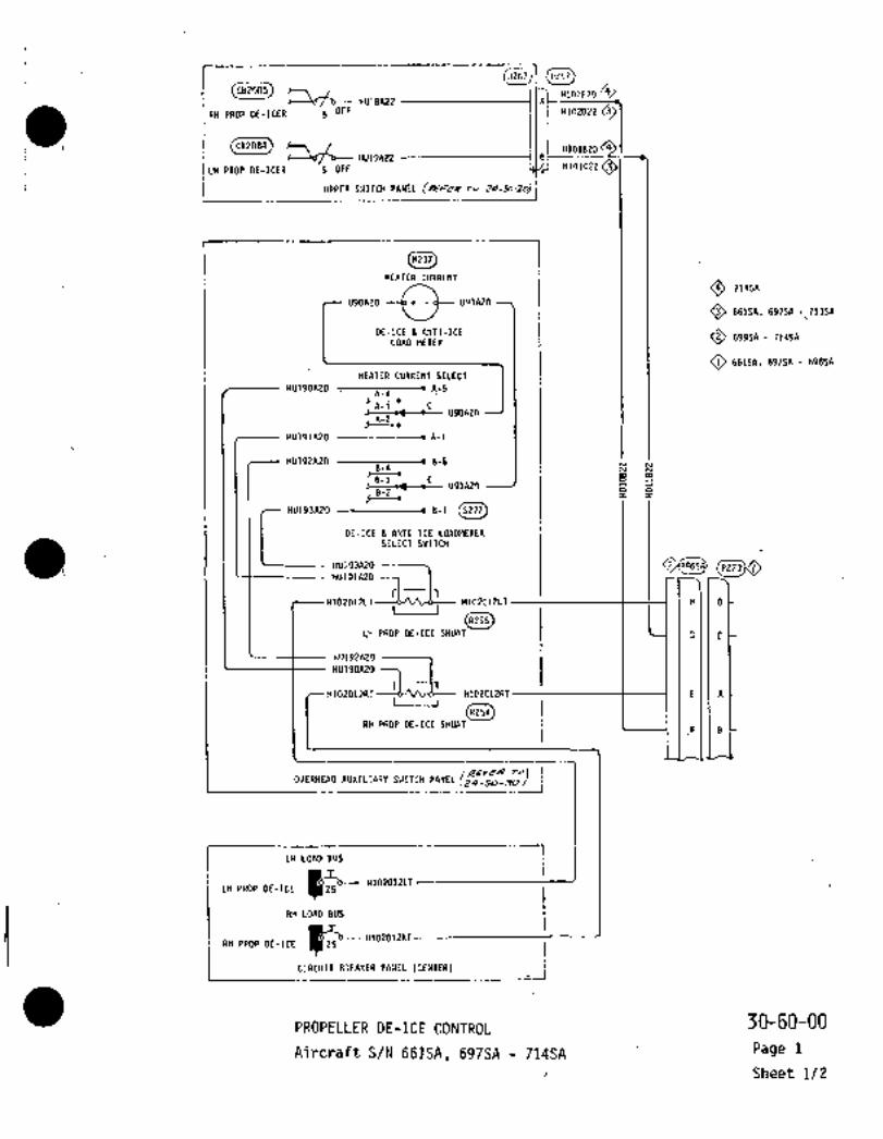
IHU18A22 k
HIO%BPO /4
RH PROP DE-ICER 5 OTF H102022
i(cszae~) H1O1DZDCB2OB4
~-)bf-b- HU19AZ2 B
ILH PROP DE-ICER 5 OFF H101C22 OI uPPra IVI~CH PPNIL jRF~UPPER SWITCH PANEL ipa ~o Zs-56-20) jI
I IHEATER CIIRRENT
U90A20 U91A20
71454
O 66154. 697SA 71354
DE-ICE ~A!ITI-ICE O 69954- 71454LOAD METER
O 66154, 69754 69854
HEATER CURRENT SELECT
HU19OA20 A-5A-4
A-3 C~--o4---e U9OA20
A-2
HV191A2O
HU192A2O 8-58-4 W
B8-3 CU91A2~ 6 o8-2 I I~t-´•
HU19JA20 B-1
DE-ICE L ANTI-ICE LOADWETERSELECT SWITCH
HU19UUO (P273~
H102D12LT--a/Vl~ H102C12LT I H DI I
(8255)LH PROP DE-ICE SHUNT 1 1 4 )G C
HU192A2r) --7HU190A20 71-1,
H102D12RT~-- H102C12RT I E A´•I I
RH PROP DE-ICE SHUNTF B
/R~n ToJOVERHEAD AUXILIARY SWITCH PANEL (24-50-30/
LH LOAD BUS
LH PROP DE-ICE I~P .I~LOIIT
RH LOAD BUS
iI ~!RCUIT ORI*IIR PnNEL~ i
(tENTER)
PROPELLER DE-ICE CONTROL30-60-00
Aircraft S/N 6SISA, 697SA 71´•4SA Page 1
Sheet 1/2

r
I
P4023 ;L´•rll[~rrldl‘l
1~4:1 :1 i:I
-´•´•-r!j*F’ HlllrlL:(N
-----11107n14 ---´•kl´•-l´•-
Il:(Llnlhj A HEATER
R )’ROI’
I DE-ICEH106D14 JI-- H35AIG
BRUSH BLOCKA493
._JRH ENGINE NACELLE
M2SA
H106C14 ----IE
O S/N 661SA, 697SA 698SA I H106D14 C
OS/N 699SA 714SA H107C14 F
H107D14 0Osin 6615A, 697SA 713SAH102A12RT B
~S/N 714SA HD21A20N ---IG
OS/N 661SA, 697SA 714SA Unless
Modified By SL003/30-001RH PROP DE-ICER
S/N 661SA, 697SA 714SA TIMER (’11.5. 580Modified By SL003/30-001 RIB ND. R.H,)
FD5A
E449
~p--- HD20AZON -I G
H109014 --O----------IDH109C14 ----I F
H108D14 C
Ht08C1I~EP273
H O LH PROP DE-ICER
TIWER (W.5. 580RIB FWD. L.H.)
G C
SLIP RING
4:
E A t H102B12RT IP4023 E405
I
H109D14 H36A16 B(A491)A49PROP1H108D14 ~1351\16 A
FIIB
~F- HIOZAIII HJTR1( HEATER
~u DE-ICE
t-T~E419
1~BRUSH BLOCK
CE#TER blLNG AFT i.._.
LH ENGINE NACELLE
LAl 1 A2
I h HIOZA12LT
X1~1DllA22
LI1 PROP DE-ICE RELAY
X2 3 (LENTER Ulllt RFT)R5Q
A’HIOZA1PP.TH102nl2RT n
X1HD10A22
r R)~ PROP DE-ICE RELAY
X2 (CENTCR Wilt ATT)t45/
PROPELLER DE-ICE CONTROL 30-60-00
Rev No 1 Aircraft S/N 661SA, 6975A 714SA Page 1
Aug 1/79 Sheet 2/2

IP288(5257)1 V’082085
HU181\22 Al-- H1)8A22 --~--113t------ H118B22
RH PROP DE-ICER 5 OFF
CB2084
~df‘b-- HU19A22 B~---- ~H117A22 17 t------ H117822
ILH PROP DE-ICER 5 OFF
I
I UPPER
STA 3050
CEILING
I (M237) ‘.M237 IHEATER CURRENT
U90A20 c U91A2n
DE-ICE 8 ANTI-ICELOAD METER
HEATER CURRENT SELECT
HU190A20 A-5
A-3 CU90A2D
HU191A2D
HU192A2O 8-5
8-3 Cus1neo
HU193A26 8-1 C5277)
L DE-ICE 8 ANTI-ICE LOADMETERISELECT SWITCH
HU193A2O STA 3050HU191A20 71-1, CEILING
H1O3A12 H1O5A1Z H105A12 -c H1O5B12 -----------´•H105812I I
(R255)LH PROP DE-ICE SHUNT
HU192A20
H1D6A12 H106A1Z -e H106B12 H106B12
1 HU190A20
H1O4A12I I
RH PROP OE-ICE SHUNT
AUXILI~RY IHITCH
1LH LOAD BUS
082071
H1O3A12LH PROP DE-ICE
RH LOAD BUS
(C820ji)H1O4A1Z
CBZO72
RH PROP DE-ICE
1 l"il ICII(IIR1I´•
CIRCUIT BREAKER PANEL (CENTER)´•
30-60-00PROPELLER DE-ICE CONTROL
Page 2
ATrcraft S/N 718SA 73OSASheet 1/2

HllBs22 (1:124)54;1;’DPCil20SLIP RING 1I
P4023 E405
H112814 H36A14 D PROP
1:124 n191
H114A14N H37A14 t
H110n14 H35A14 ~I I,,,,,Ror.- IcEH117822
I DRUSII DLOCK
I _1\493 .iR432
P446
r
H10aslz -18
H116A20N --IG
E448
RH PROP DE-ICER
TIMER (W.S. 580
RIB FWD. R.H.)
H108812 H10sn12
H107812 H107A12
P445
(E44d)E449
H115A20N ----IG
H107B12 ---IB
_ H1OSB1Z ~--7 i i 1.
LH PROP DE-IEERTIMER (Y.S. 580
R18 FWO. L.H.)
8106812
115427
rellozo ~L)O (E405) SLIP RING
HlllB14~I 1(361\14 D
H103814 H351\14 1 A
PROP
837116
OE-ICE
C IILhlER
880511 DLOCK jE419
n493
CENTER WING AFT (88)LII tNGII:E NAEELLE
LH105B12
Al~lhA2 Hlr)7A12
H117B2P
LH PROP DE-ICE RELAY
(E450) II~-- H119A20nX2^3 (0ENTER WING AFT)
E450
A’ 7~-- H108A12H106812 h
U
,1 K402
T j; RH PROP DE-ICE RELAY
(0ENTER WING AFT)(E45j) O- H120A20N --´•12~E457
Oa,,,,it NOt I~drii.d 811100iiIO-00L ´•IQAircraft Modified By SLD03/30-d01
30-60-00PROPELLER’DE-ICE CONTROL
Page 2Rev. No 1
Aircraft S/N 718SA 73OSAAug 1/79 Sheet 2/2
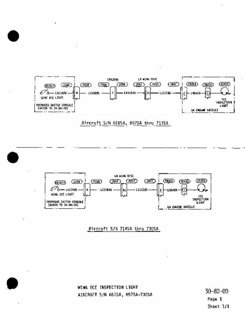
I 5143050 LH WING DISC r 1(P268) (5921~ (P9001)
d76-LU11APOWINGICE LIGHT
LlllE20 -a- -~i?-1IcE
L11182O LlllC20 L90A2O
INSPECTIONOVERHEAD SWITCH CONSOLE
I LIGHT(REFER TO 24-50-20)
Aircraft S/N 661SA, 697SA thru 713SA
I i LH WING DISC I I(c~Ti) (PP68) (5421)
d76-LU1IAZOWINGICE LIGHT
´•L111820Lll~C20 L9OA20 -K 1
ICE’INSPECTION
OVERHEAD SWITCH CONSOLE LIGHT.(REFER TO 24-50-20) L ~_LH ENGINE NACELLE
Aircraft S/N 714SA thru 730SA_
WING ICE INSPECTION LIGHT30-80-00
AIRCRAFT S/N 661SA, 697SAr730SA
Page 1
Sheet 1/1

CHAPTER
INDICATINGIRECORDING
SYSTEMS

I I I sTA 8035(8201) (J~iji)I
cC D103A~O 00-4 0103820 ---c- 0103C2I)
(F1203) BC D11)2A20 0102BZO ---c- D1O2C2r)
T
D!~1A2ZAC 0101820 0F-2
IOUTSIDE AIR
TEMPERATURE
INDICATOR
LH INSTRUMENT PANEL
ILH LOAD BUS5251
o~ulrzz I-~-- mmc2r ~b 0101A22
CB248
OAT IliD
i [IRCUII BR[I1CII ~L.II (IYU)BREAKER PANEL (FWD)
(MT301)OUTSIDE AIR
0102020TEMPERATURE BULB
STA 8680
0103C20
0103020NIr
OUTSIDEAIR TEMPERATURE INDICATION
Aircraft S/N S61SA, 31-20-OD-r---- Page 1
j Sheet 1/1

CHAPTER
LANDING GEAR
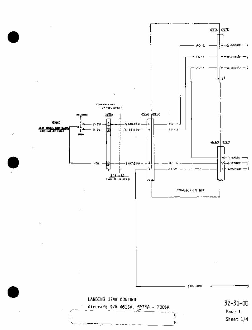
II
FG-Z ---I I´•rtG108026 J
Ft-J I~t-G104820 --5
AG-l -----1 Ir tblCi~820 -5
(51A400~C.1000LHIC~LOUm)
YDTtORIW QB~eO IPUPU e-zo 1=´•1_ ’,0,,i0 1~1 I FC-Z
tsalLWO IW ~QL) 1 J-20 20 -1 ~I Ft 3
A ~-GI15A 20 -J
1-20 M i GI, 72 20 lit I AF-5 i I CC;ld7AZo --I
1 1911 e~-Ja 1 (nl-Glo,aroSTAloaO
FWD BULICHEAD
BOX
I 1
6,oiAzo
LANDING GEAR CONTROL32-30-00
Aircraft S/N 661SA,~iS´•A- 730SA
r-I
Page 1
ij Sheet 1/4
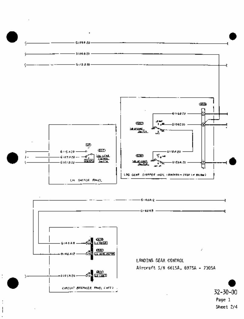
G1088 20
Gio48 Zo
0 113 2 20
r- aeZ?B
1168 20
urM
f m, G104Ct0
r 1 ca upronE
Uo!
luPI
15 Aio ----o_
I I ~-----6118A EO
0 lo7A ZO=I~J. iDG GEAR UPo WO
1 ~PbLIBPI,
5 G,orszo ~YLIftL G(~A ZO rs
Sw~TCH I~lcr
Nm~P
I_
L~i BVITC~ FAME_I OEIIR STDPPER,NSIL (JT1S(.O ~-34W
I0146412
r
G140A8
I
0146AIZ
LLC MOrDRI1
Gr40A%
gelot)
LL4 DOOR F1OTO~1
LANDING GEAR CONTROL
Aircraft S/N 661SA, 697SA 730SA
PO ILe coNT1
I C,RCUIT~ 32-30-00BREAKER PAN~L (AFT)
Page 1
Sheet 2/4

clk~4 -------~F----‘ 6142412
MWoR3
ALTUATOII
C I -1 tt--’G108820
0 --~----CltJA ZO
A 20
’GlO 64 It /46 B IZ ---------~--r
t---G1~58 20
G140A8 ~N --614088
6122 820
(LB~L,
t-tOb
I-tO
It ’EVD DIIOR CLOY
~------J-to(RnOWCE STAQ)Sb)
uose
I I I I I rI -j
G117Aea1 I I ILILI I i W
G
Glog ozo
G/Oq~Zo
I I I ))I I I I IE-----G1Z5ftO
G109A20 6-to
01080 20
GIO%B p0 -20
G12SC ZO I-ZO
CrvD DooR OPE~
GI26A2 UHIT rLH)j-zoILH BUL~ STAQJOO)
GI 1 44 20 L- 20
5-to
(;H BUL4C
t 61Jo4 B r~ OUl)tHUD)
STA 4025BULlcH~AD
ZZA to 2 20b
i i 78 20 1-20
’J-Zo FWP DOCR CLDR
icrosC (LH BU’LC~
6 115820-----~--G,,5C 20 -9- 1-20
G116A t0~i 6,~6C 20 -e i-20 -o t
RE~.eR to C15 74 20 0,5’18 20 ~Z-ZO(LH BUL6E SIAJiOS)
ONGUo
LANDING GEAR CONTROL 32-30-00Aircraft S/N 661SA, 697SA 730SA
Page 1
Sheet 3/4

’1~-6148qn n;’_LXr poon
_I~C--C’4’BZO´•*i
IG,43CtD
iCaob~
,d L/6 Doon
’t-d nit
OPEN ~ULI. I ’G 14eA% A
Z~rP31G 145 A toyC----GIZP4ZD (Yso7l
´•I~p---- G1sJAB N -~SQLni I)DWN I~LAT
’1 C14iLg/2
A’ I ’C141AB asslJoss
X’ C14QA20N-----91~´•I muD 6~uz NDmR
G,ZZBZO ~-ti---G143 4 PO
7I--CI--~IIQISZO(CJbl)
MwS~ NLT~B
Z- O 119A20
t Glo4 E W ----o~
’L GioBDZOi T
’ppW CPNTROL.I i~SI SwlTCH.
I G I roAeo _1~,--,,L---´•GlOqA ~´•a
rAND GEAR CDIJ~ROL RELAT PA~EL
B(ILM IYTERlclARD)
LANDING GEAR CONTROL
Aircraft S/N 661SA, 697SA 730SA ’32-’30-00
Page 1
Sheet ~/4

Fa(YYVID BULknr?P_
I5-50 ill3AZt
:6-CO
6P .L~ZPC~D ~-tO C/SZAZZ r
-Y1(SBI~O Ut
mLsRr
~J
L-ro tlssAtt~aul t 157CZO ---5
STA 1080(51A ha-~ooo.
Ln
(sstoJ)
G157D20
45 *u~nnluh(u~
´•Ilt>---- GI 58 B 20 N -----~1 51)5 A ZO
I """C,RCUIT BR~AKER PYI~JEL(ArT)
G~soAzo
I
LANDING GEAR POSITION INDICATION32-60-00
Aircraft S/N 661SA
Page ~1
Sheet 1/4

1
CIBe~L)
S tn39 22 F-)5P 21-722-2
AC-lo ------I /;u(C-r
,II I’FL-I ----7 i’ Lt---,,--- G- P kC~
I GL-l -----~lf
9 -55 ----11~Y
1 GL-Z ------tlrt--~
r; ~6155Aee --------~i;n
615 7C2o ------~’nol ~---+-t F -)OP G-4PP-3
AO-,6
AG-I5
G-~s -----lls5-12
Y
AL-I (h C~
A -9S ------1: liu’S´•~l
F-ijs
I 2 ~soA ZZ -)ZSI I I I L--As-,5
AG-16 (NC-S
r_A.F- 25
1 (i
I rin I ~D
A ’B P
tn OA-2P 2
--lo~C.i e~ i
AG-lo \Cr*ly~
r jP
ij-4WnnA16
hQA-BP O 04-511 -----7~ IHk--~
V Arr-t s
g( A 1(-4 \j ~--5
i~_- .I I AK-3 Ib CT
ul IAK-I IJiy
(SCPC 1 rTr CO~lhKC TlOhl BOX
I I
´•I0 A lacRA~rNor Mo ~INED B Y 2
OAlec~rr_
LANDING GEAR POSITION INDICATION 32-60-00
Ai rcraft S/N 661SA Page 1Rev No 1
Aug 1/79 1 Sheet 2/4

132 Ztr
I------~c--- 61 s 6 Ctt c
S~------G lIJB ZZ 5
I---~----------- 6 Ist c zz -r
8 150 11 tZ 3
6 1538 22c
J--~-------- 6 1 s 7A ZO s
S------- 616 ZB ZZ r
~--------------------GIGIBZZ I
G 150N ZO
r
~--G153CZZ
2~u6 150 0 tZ
Ra~r*IOll Ilewf AC I
[Ba]
L~ WYI LO(~
LIMII
ui
QI~3ii9
*t!-usllr
i;/G M~LTI
(j150Pt0 I I’U
dLLAL F~jL----tl7tAt0 r6155222 I I ’(BZi~P2150220 Locn
COS~57820 IMlunll LICmT ir--
CaIG157BZO
c-gs,sbozerslo~
I 615782Dj LblSqA221111111 cumur
i ~sbo2t
i sulrcn
I----C-GIS9222 ,,,~J
t~61.911L--16164222
6166822
6165AZZ
G16J A et
LH 51111708 PLIAIEL
OAIPCRIFT~DTSR0/5/32-a02
LANDING GEAR POSITION INDICATION 32-60-00Aircraft S/N 661SA Page 1
Rev No 1
Aug 1/79 Sheet 3/4

-Cb~ldHCE "~r
f ‘G)IJFZZ ~CII3FZt
S-------6156CIZ r~t I 1
(6rA 56011. W´•COO)STA 51135
I---------´•1 i I L--- 6 156622 ------~------(ilMB 22
:0152C22 6116420 ’3-20i’HCG UP U~IT S~YIT(
H(RII)(SPf~~isnaze j b1seo 22 cRlt8uce Sl4 9990)
ii113J22 -t-’2-20
’cesu) ~e,
G I I 3 B 22
6 I 3 0 Pt 6 ,IJ c ZZ ---I 1
-HLG mWIIUHIJ SWLTCH~RH):61618 P~ 22 121 o~u <59 sue 915 5LOL~
G150322 --fj
Giao 1122
Glsole 22‘t~ 4-20
61533 ZZ 5-20(56 WE SU1435a
G153AZZ W t--’6-20Clb~L
(rss,~
6 1166 20 --´•´•---CJr--´•----- G116C 20 --´•´•----3- eo
6115 5 to ’6115CZO -------l-Zo
I~ a~T ~wrmG157A PO 20 2-20(16 ~vur suscos)
6175420 --c--6-20Ib
6 1’134 20FI -iI 6173820 ----~---4-20~af
61’1252 GI7ZCEO ---C--5-b
~D
c1534ZZ:rra MOR CLan UWT ~Jrmw
’(LW suqe 5959559)
OIJo KtZ ---rsr-- ;6-20
~icru
:oisonzo 3-E0
HLe 1IP LIWIT SWITCHLLH)´•~lstBtz 1025 ZZ----~---i-20 "ip ’(LH W1L6e 6155979)
G11jDZZ IIJKZZ----~--i-tO
’cesw 43~
6150 6 22 3
6113522 l.r ~nLG 09991 L.IHIT SWITe~ ~LI]
’(LH
(i16tB22 6162622 2~--6(t II
STA 48 ZJ
32-60-00LANDING GEAR POSITION INDICATION
Page 1Aircraft S/N 661SA
Sheet 4/4
LI
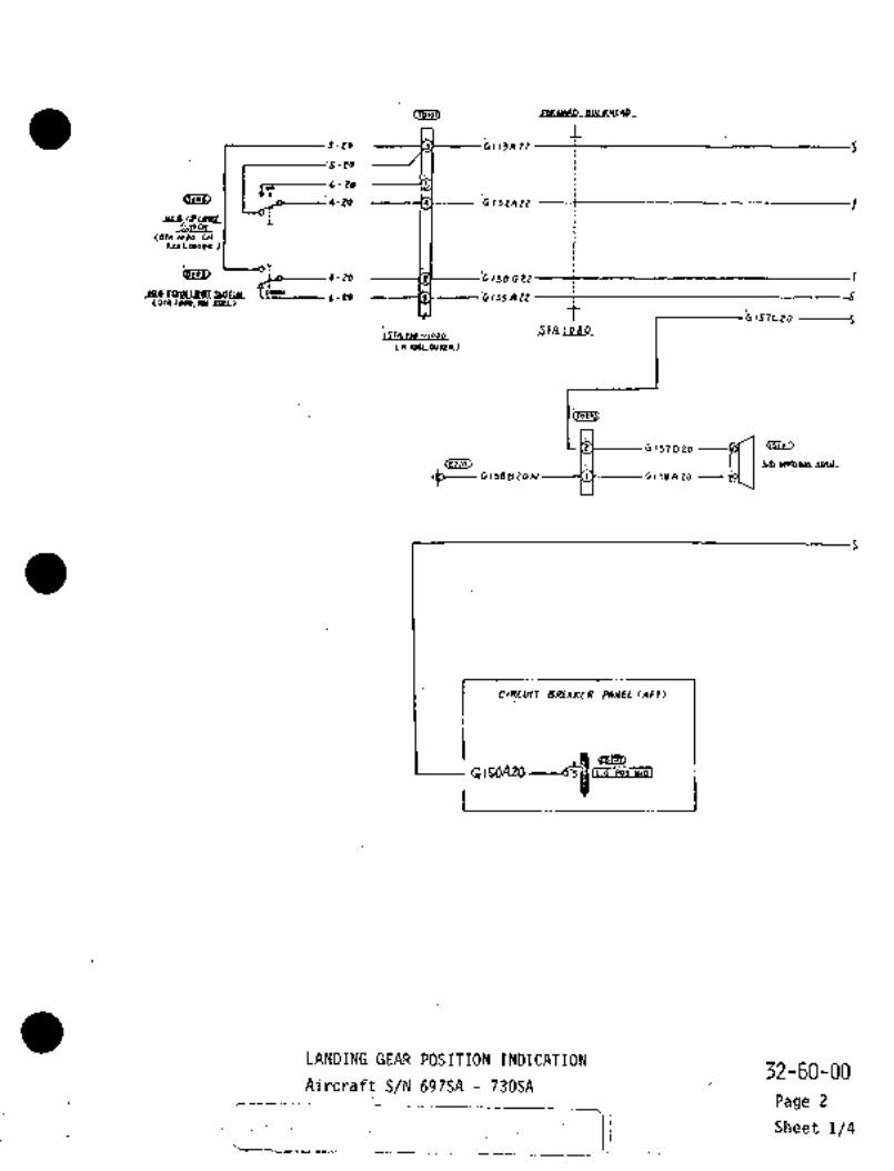
+DplaMBeBVLPYE~P_
Is-to
i
:S-CO
6~’ .L~20di~ 4-to -f
JI1UP~RlblL L
LH
*uLanP
~u ~-,50GZt f J4F(i"
(-88 t1ssAtt r
i 157CZO ---5STA, 1180
ISM rpa
Ln r%LouRa)
Gij7D20
cfi~G158B 20 N G158A ZO
I
GrSOATO IL-G POS
I
LANDING GEAR POSITION INDICATION’32-60-00
Aircraft S/N 697SA 730SA
r--------- Page 2
i I Sheet 1/4

i~Le, i ~f, I~D
cre~u
c_ 6113A22 r( F-ISP -7P 1 19
P-26-19
(S1I~Fa)
6 /52 AzZ---~---fv I t--- F L-l --1 Lt-----G- p1 ld
L-l ----II1!
-JS uCI
GL-Z ---ill
LI~FcxjZZ----l I t_ ~27- So~osEE IpJI 86-3r 61g5jP1Z m
ADI ~--C-C F-1oP -4PP-3
-16 90
-IS 99-13
Y´•
AL-I----I Ihl S
A-4S--I ii~S-ir
F-IJs
5~ C-C- F-I~S I I I I L~A 6 -15 --i I’H
\c/
I AG-16 ---I IN
r ~3a-:-ii" I
rI~i" i I GZ~
B-I
A F 25 ----1 Ii I I
rce~u i Bfi~
AG- (O --I ICr ancarl(imuT
LAK- 9 ---1 JE t--r
I6
7 P-6P:I:
kl InH-p
i-9clk- 8 --~f In
---tn00N WiouS L I´• A K
RELILI ~t--- AlAcr-e IB’
2 AK-4 j
u
AKIJ ´•Ib
i~L 24-50-00
AK-I ;9
5EEI COnIhlECf,OhJ BOX
1 I
´•I8 718SA RND SUBSE~UENT697Sn Tpau 7/764
32-60-00LANDING GEAR POSITION INDICATION
Rev No 1 Aircraft S/N 6975A 730SAPage 2
Aug 1/79 Sheet 2/4
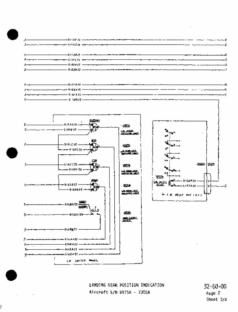
J G113F ZZ
5 G(C~CPZ
.C Gl,JB tZ
I C15~CZZ c
G150~ 22 c
,C 4 1538 22
5 G157At0 c
5 0162822 c
G161812 1
r G150N10
Mlu´•rpa
5 CISJCZE
G ISOD ZtJ; L/b
~u´•i
Qti~ ~9‘-S:G161C22
sR´•~0150020
I IC~t
iI I 1 I bJ!
Is2CPZ .4~53150F tO
vs laLle P~p-.,I i hti
18~81 G1SO P ~B (i,
S~--------------+--G 155822 dUdt cO´•"-L-- ~i 1 7tA ZO ----I I;C150820
LAP LOCh
N~lcanR I~wI
5 G1564tt------~
an~
61594
CZ~L1 sultcn~ c2lmu~.
E O1C4AZZ
tiiil5 GllbAZZ
4 1 6 3 EZ
LH SWITC~ MN~L
LANDING GEAR POSLTION INDICATION 52-60-00Aircraft S/N 697SA 730SA Page 2
Sheet 3/4

I GIIJ~ 7P _: 6 1 rj 9 22
i6/564 22
I---------G,56CZZ
SmffPJ~
i I I I -b,,~o ee’0"-4C i;i~D
,---------1 I I L-----G156C22 ---------+-------61568 Zp
1’O ~sctCZ2 Gll~kZO ’9-20
’nLG vp LI~ITSWIT(H(Rn)~152822 01599 22 ’1-20 -a ~Rn 8ura sT~ 5490)
iiIIjJ 22 -t-- 20
’ce~YGI 138 tZ
61130 22 --------[iFI---GIIJCZZ 1
:6 16 1 B 22 6 16 1 A Ze -------I ’t HLG DOWN UNI~ SHIITCH(Rn)
01*U <RY BuQ 515 5C~s)
6150322 ’3
61501122
6 ,so k ZZ ------~jf------ 4-20
61533 tZ o
sue SUQ)~o)
C15JAZZ Y ~----’6-24c16~t
t´•´•-- 6 I 1 6 A 20 --´•---~Jr--´•´• 6 1 16 0 20 3 20
6115 0 20 6115020 1-20 (sji~
61574 Zo ------m-------b~57E 20 Z-zo ~FSII SPI~M(LNsuLer SU6CO~
k-)------G175A 20 --~---6-20I~
cP---- 6 I 734 ZoFI I 6173820 ---t--4-20
61’72826 6172020 5-20
CLOSLOJIOb-Z0
GIJjAtZ W ’5-20 Tr ’~ur, 4009 cLoSE L,L(I~ =AIImw’(LH BULQE S(MISO~
OIJOKtZ a-to
crst~
6180420 J’20U:
MLB UP LIMIT SWITCH(LH)t,5r8 tZ -------~F--t-e 132 E 22 --~----i- 20 -QLp ’(LH BUL6E STIWIO)i 6/13022 7 IIJKZZ---t--i-tO
~cuw
6l50LZ2 Ij
6113E Zt’(Ln bUL6E ST~UOU
61s2et2 6ICPAPZ 2
t57A 4 Oy~
32-60-00LANDINGGEAR POSITION INDICATION
Page 2Aircraft S/N 69ZSA 73OSA
Sheet 4/4

CHAPTE R
LIGHTS
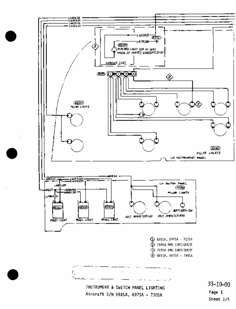
964ci2o909020
L902E30L402Ci20
r -1L40W20
7-rPLqCARD LlljHT ~DR Hi HEAT
ii i I
MODE OF HEATE~ WINDSI~E1DILH)
2 3 4
I
<psze~2
PILLAR LIBHTS
jj
I
slLLAR L~GlfTS
LH INSTIZDUEUT PIIUEL
X,
L404010
r L409CZOIVLH SWITCH PAUEL
t; ~L--L4WBZON
(D~jZQb)Lq04CTZO L404H10
X) RLuB LIQHTC
L4WF2O
~j BATTRZ~-SW
VOLT AMMETER!L~) VOLT AMMETER(RH)PANEL´•LI~HT P#NEL LI$HT PANEL C#HT
Ok61SA, 697SA -713SA
Q 714SA AND SUBSEQUENT
718SA AND SUBSEQUENT
661SA, 697SA 714SA
j,
33-10-00INSTRUMENT SWITCH PANEL LIGHTING
Aircraft S/N 661SA, 697SA 730SAPage 1
Sheet 1/5

L40ZEZ~L402Cr20L402DZOL403C20
OLeoz~p
~uu
(P8243) a~
L411JTO-----------------
O
,I~ur IYns
C; r´• r
cclns4rnugurwn ICEnITER INSTRYM~NT
Q 661SA, 697SA 713SA
714SA AND SUBSEr7UENT
7lssn AND SUBSEQUENT I I L401HZO
6615n, 697SA 714SALC1(48 30
I~3-10-00
INSTRUMENT SWITCH PANEL LIGHTINGPage 1
Aircraft S/N 661SA, 697SA 730SASheet 2/5

L411Clo L4//C 20
LnllJ ~o L4/IJ ~Q
Lal~Dy,
Lao4nle LQo?Mzo
L402H~DL401F2j
II ~1
r ii ~4//azo
PLAO)RD MR ~I YEAT MODE0F ~1EATED (P~)
~L411NZO
p~uRa L16HT
R~
1 411030l+llC20 r4,lplo 4,
L~IE2DLOllntD
PAIJEL PANEL ~E)
UGHT LIGHT CABINPPESS iColvT
i. L4(rlP20L41 DIFF PRBGS ~FID
OF CLIMB INDCABIN ALT CABIN RATE
RR swncrt PANEL
L4~12aON tlCHT
Iqo4Mlo L404N10412 D~0 L4.12820h)
O 661SA, 697SA 713SA
O 714SA AND SUBSEQUENT
O 719SA AND SUBSEQUENT__;_ __
~66lsn, 697SA -71451
33-10-00INSTRUMENT SWITCH LIGHTING
Page 1
Aircraft S/N 661SA, 697SA 730SASheet 3/5

(EZ~yil <J~i)
L40cC ao -----------IBL´•I 4 -sp
LqcqcL~o )-----------n-,NL102~t3 -------(8~1 ~-------A --~OP
L402HLqorFreL4cz02e F-dP
L4ol c 20 TX I EF 7
<r2oi,
L4DZtEO --------~P I t---- D-IPLoo3CZo ~Tll D-7S
Ld,,J 20 ----------1~1 E-3P
L401HZO ’jl i E~-7L 4~48 ZO
(PI ~31
Lal2Dlo ---------(f( C-1FICdW n 20 ---------1 v c-lpLal/CZO c -zp
U~ LaSD guSr,I,zo"1 linST Irrl
LLl~an, i_ C~RCOIT BRLiAKER PANeL (CEF~TI
O 661SA, 697SA 713SA
714SA AND SUBSEQUENT
718SA AND SUBSEQUENT
661SA, 697SA 714SA
I,
33-10-00INSTRUMENT SWITCH PANEL LIGHTING
Page 1AircraftS/N 661SA, 697SA 730SA
Sheet 4/5

6-7P
J-3P
cJ?is, ~ID
I--C-ip
(I;BgU K-4N 4A-Y)P-------- A-DP -----´•I I IN-I5
C
--A-I~J--C-IN N-12
n-H( Hrc-ic
I I II I (YYua
fRI~ AIL~R6N 1JK-5 1ND
rI--F-4P r-loe K-1W Y aun)0-19 J-a~
I I I I I -gv CEHTEP ICo~TRoL 004 I
iIJ-%
--E-3P C-LP
p-lsJ--IP
0-33ci~aw I I I I 1 I Is
~a, ~HD~ap6, I
"I V105CPO Ilel~
3-43 1~1 J
J-4PI IQI L403020---1 IH 7
LAI
J-,P 141Lt4ijP20 bSIISZO~ 1MfC~ O
4o4Fzo ~1 I~T-.´•L--JM--1 U
140nzo
BOX jI 1
O1Ar4AzDN----clll(6H~ ceri~
~OXr$WR(EsS Q9~E $TA 30~0 1
GL~FkrO~
20,--------
0 661SA, 697SA 71356
Q 714SA AND SUBSEPUENT
O 718SA AND SUBSE9UENT
661SA, 697SA’ 714SA
’i __--~L_-´•i-?
33-10-00INSTRUMENT SWITCH PANEL LIGHTING
i Page 1’:i Aircraft S/N 661SA, 697SA 730SA
Sheet 5/5

´•::45211 C~I_) ~COCKPIT RELAY BOXDIMMING RELAYI
h__
7
(R206 );ADJUSTABL_E_ RESISTOR i2WHITE
BLACKL503C22
L504A22
BK-1 k L503B22´•RUDDER
TRIM DIAL
B-1N L504B22
ri5209WHITE --7BLACK
!DS204)OB251) I
IELEVATORTRIM DIAL
r CB2040
CD L501A22 1 115VAC 400Hz
i CIRCUIT BREAKER PANE~
TRIM POS
CONNECTION BOX I
O Aircraft S/N 661SA, 697SA thru 713SA ~CO Aircraft S/N 714SA thru 730SA
33-10-10TRIM INDICATOR LIGHTING
Page 1Aircraft S/N 661SA, 697SA 730SA
Sheet 1/1

i rmo~n ~iB> IINDLI~S
J´•7s --I I.cl uolJ11---l Is~l WU1IIZZ
FJ- I -I I,sC--wzs2~----l I R WUzz~2r
~-----L-3P-I´• ~2UP.IO --L-IP-- L ~I,TCI) COI~IOLT
~o P4Sd~2o)
IdPwlo/al2
F-ldP
(llaclL5)
C~(j~6,
t17X
3 22
-------tW2,a412 luZo,B 79
CAVn6*I-P~H r~ H/c-DZ~ZZRP-F~T 7t----- ~v´•":’i ~:I --t------l a-ir-rt w:CIE7~j L) 1YZi)lD 7’L
-t
I:ru~ I I C ~L-- :I:703FI;-)-t--lf
--O- nIZclDn I Lvh?/C~
----1 le
2
-´•--vlni-)1---1P
C~ie?
L I__i II I Ii,, 7~,58ri --1-1 I t--- L170~A7P ICi
L´•~_
V
Snn~l,o __JW i,
I-----*121IA?D------l L
I------
I ~IIL.x J(LLE PANfL
w3olnn--r;´•1~----
O RI*rln~r S/hl b97SA 713SA
O
OR$GBNAL Rs
RECEIVED Ca~ka
MASTER. CAUTION WARNING LIGHTING
Aircraft sN 661SA, 697SA 113SA 33-10-20
Page 1Rev No 1
Aug 1/79 Sheet 1/i

i r" I
x- 7P 18 I2LSl A Id
Fn-,~ IN PCYIAIO
C~8_29
t-´•--C.3P-- --L~IP--´•-1 i rp-lo Bell
LXLPY)416
(nnl4u) IvnvA12F-14P
~RT6)uxwrthav
(rs?L~ aasu~ avo~m)
8 2 A22
2olC~~1M) ~5TRI)
~421
~2/OA71------t-U2,a4m *20/82M
ro
19snz Wi~oZnZZV2OjE7’1 O W202D 22 iy:r,^c 7~ ---C--~ B
I t IC
W?o:i~
(6651) le~----)YIWP?) (11~34812 re
i´•---
------vibla~i--´•----IP
R?~a´•R N
I_ ~sur/a\´• C5-r~) i r---- n~sSPlp---
~------214q4n---
W266B22 "70?lA’)P d
--O L----Elrl~l\??w;06L)n V
_
slRao I C~G
L---- V2 I IR~D-----´•1Lr--- wRsla~----IF~-----wRMrxn
t----wgol~0lSIYI~ P#I~EL)c----w~ola´•n---
(E 2/4)
ORIGIN:Ab As
RECEIVED
MASTER CAUTION WARNING LIGHTING
AircraftS/N i14SA 30SA
33-10-20
Rev No 1 Page 2
Aug 1/79 Sheet 1/1

,-____
__
.1,
ri""’^"/4 -$O 20 ru´•i C r o c L´•)´•lilO L 51bd 20 c
Dv~pHrao COLJSOLd J LIOI410
or pHc*onn~xcauraEOYPRH~AD SO~Y/nU CbUbDLh
ces~ CS14S1DI)OCH ´•d
IO-Ch -10Y~-- HCI.CO-P-
c-M)-CO
HAIC LmC/r Af~T I
r~m-c/R LXjH~/AG IPANN
r I-LYICn
f
1 j (AFn
"t~ i ,f~ "P)
lr\"2~9
i b rv~--7IL3A20~lplL--L~A2D
ACT E/4CUlZ d´•Paa*~ PnrcL
MAP L~H77-~27-OP00)
uc La4DL~~89
´•E"=LSOii~--------------Applicable to aircraft S/N 661SA when used’ in I~aP LYmTI
conjunction with MAI Drawing 935A-4O01.
NOTE: See MAI-Drawing 936A-4028 for aircraftcwr,,S/N 697SA and subsequent.
ROOM LIGHTING33-20-00
Page 1Aircraft S/N 661SA, 697SA 730SA
Sheet 1/3
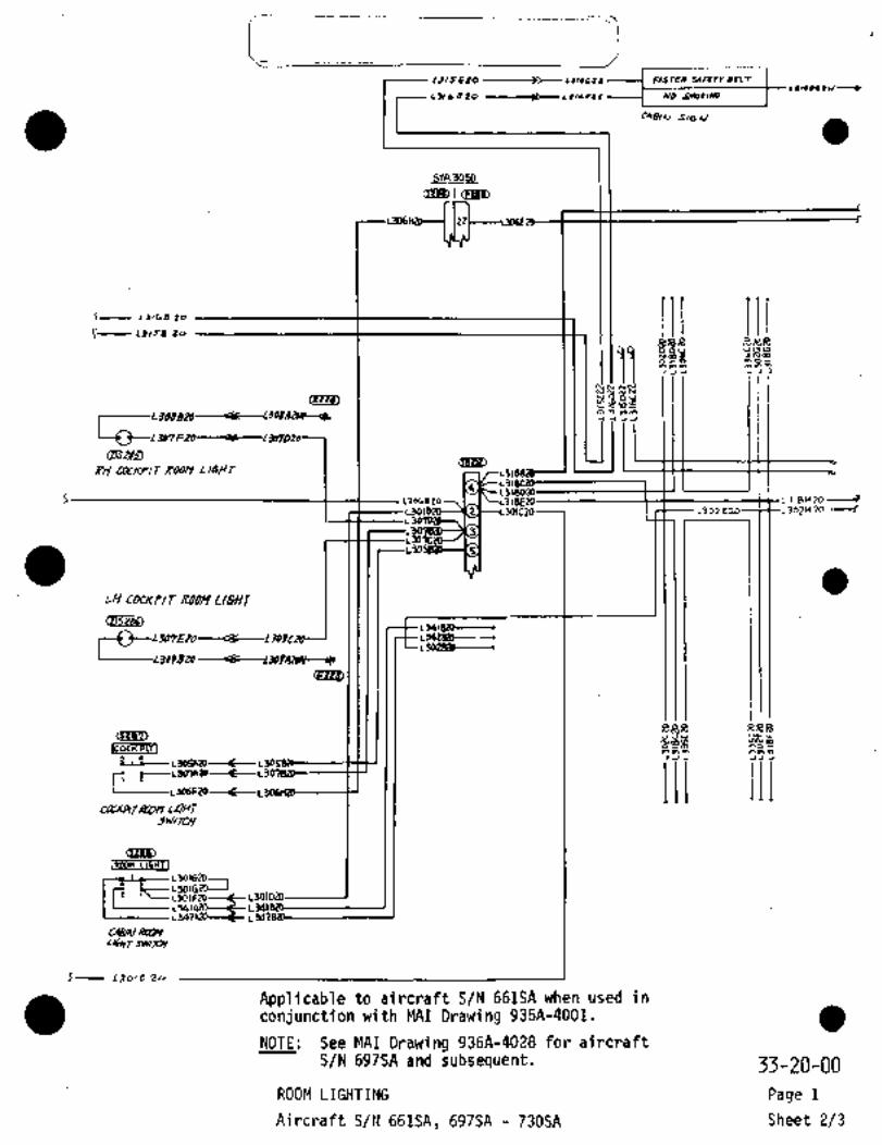
13/5~20 II,LCIt FASTPIV SARTI BCL
Lflb020 -------´•)$--1 NO
Cag~N ´•S/GA/
I I ii ril IIiC LII´•rL~ Zr, I I I
~RR
<EZ~’V) 85
U,~s9~s
L
~H CatKP/T KODY L3
I I ’IL318H10----IL332 E 23~itL 302H 20
LH COCKP/~ ROOM LIGHT
msz~Lwlezo-~
~---0--LP7 L3028ib--.L~QZBP-
ND~R RR~a
-s~;?-Le--L3051129 1
)11 111r; iLJO?AP
I LS06FZO
CLLjVM~4UDn LIGHJJHI/JU/
CIHIDiRwn LIGHTI
L30Y120L30IGZD I
L301FzP---t
~61/NL/61Y~ Jw/P/
f-- L3oic 2i
Applicable to aircraft S/N 661SA when used in
conjunction with MAI Drawing 935A-4001.
NOTE: See MAI Drawing 936A-4028 for aircraft
S/N ~697SA and subsequent. 33-20-00
ROOM LIGHTING Page 1
Aircraft S/N 661SA, 697SA 730SA Sheet 2/3
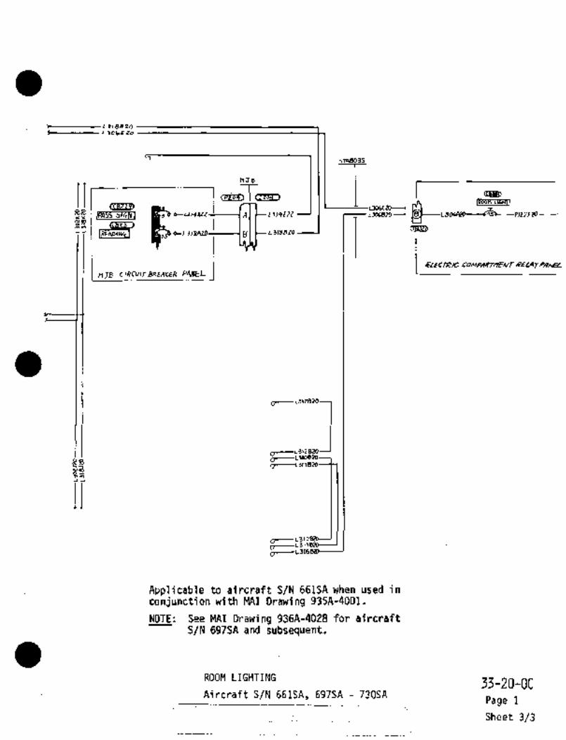
smBo35
r I ~D
j U06E20----suG~n
IREADIN-~1 g ~-L3 B
--P)27F20Rns~clN1 ~uyW A L314EZZ
(E823J
:::I~----Lstoe2o
C: L311
mJ=
i i
2~-Li)
Applicable to aircraft S/N 66134 when used in
conjunction:with MAI Drawing 935A-4001;
NOTE: See MAI Drawing 936A-4028 for aircraftS/N 697SA and subsequent.
ROOM LIGHTING33-20-00
Aircraft S/N 661A, 697SA 73034Page 1
i_ __.IISheet 3/3

~I cc~st,´•a--- L10 8 B’FJ Q L 6 q~o~E) ly/N~ T,P
L1o5 E~ S LI05FiTO v
L,6Hf_j(wssa5+ANKNSP78
(Pi164)
~\03 B~ 0 Ae
´•s--- L109A CL I OJ 0 20
B?fRT/NG BWLCDY LltnT(LOW~R RISE~E)
~7AIE00)1 *IN~ PISC 1r
(iB207~’i
~51)
BE~CDNLUIZA 20 7
L U/3P 20 u
L105CiT
NAV Il~ls LU/SAZO s I L 1 05 3 to L.105020L13JI~ZO------------
E~HEAo ~S_W/rCH CON601~ (R~FER T~ ~4-5o-2rdl
C32~7)
L";i.
L105 H
ce~u
´•wIsz´•r85-( Z
LrOSJS~O 5 io5KZe
\OrA’i~OwrNci np
LIGHT
np TANK
31-UO-0bNAVIGATION LIGHTING
Aircraft S/N 661SA, 697SA -:730SAPage 1
r: Sheet 1/2
Id

sTA9nS
L10 D ~O IlO~fE’ZOB
I loA C
LIEAUW LIWT
661S~ 697SA c 705SAI~ATIOIL SIWBNIIWI
~s
C,lo28LO--11(5~
L I IOA 20~J(BL18C
~..-1B
L10 O ~OCPED)
~hD7iSTINt BEACON UbYT
cEja~ 714SA ANO SUBSEQUENT
L~ /02 820 ----------llt~
----L/05M20~
I´• ~I (h9 :X; \8
706SA 713SA ii~7nTrNe BEACON LIO1T
IMRTI~AL
Ci~
11osP20TA(L LI~HT
LlogkPO :STAllfi70)(STA9030) ~i3
j
31-YO-00NAVIGATION LIGHTING
Page 1Aircraft S/N 661SA, 697SA 130SA
Sheet 2/2

LUZOA21
~r
1 (5~27/)iP038~2 E C-Lu 2~
(osloit) IOFF] lKFilL’iroitei~2 F LU 25 A~2E
la~ LANDINGL~o3Citit LI~HT
eLoSE L~o2C21 Swl~cH
;S IAHP LEOQA18 IEFI100 12110 L~o8BEP C_ LV22 A22
4"lorFI
Le07 BE it b L1124 Ai~20+ 001 IRETI
LZolDZZ
5 IAIVD/NG L/GHTIRHI(srAao) v LV 2l A ~tZ
21:
Q, 22R~WB 9P O
gTA)050 Ov~aHEmD suv~rcn conrsoLPV)
rH I 53e8
o
z
L20~C it2RH L06 d R~V CI~
1n RHL~AOBUS
ctosr LZ07C2il L2//A 22
LRHP
1 ZOQAIINLS’O~A18 LedBA 18~9 RX LDS~ ITAYI LAHPW
a T1H LPG~ TAX/ CaAI~cazd~l
LIO1A99
1H 1Dlid TRXI LAMPLANDING LIGHTILH) ~TA V75 LZo5AIB(sTAs/o)
LHLOAD Bug
iiO lllllallrr YI b~isa 697~ Ne, 7~sl I LIRLRCWT BREAKER PANEL (AF
~IDPO)
Al´•ecRAFs -S/K 7/4SA 7JDSA
W
to 02 -f-O
r
C~ ro
r

e~OCI -4A-16---c----PTTL5B16-----cL40 Z PTTLIA16
OCI -5A-16 c-----PTTL2A16 L408B20N --I I P C PTTL2A163TAXT661SA, 69.7SA -698SA
CENTER W~NG’FORWARD
UPPER SWITCH PANEL~o ~o
r0 24-~5a-20)
SWS 5450 RIB~ WS WS5450 RIBLH WING 2590 RH WING
~3 11-1 c;a
(d)~rPTn-4C16 PTTL-4BI 2 3A16A 2 PTTL-3B16 PTTL-3C161
L’TTL/A1 TTLIB1BN TTL-tB1 TTL-2A16N´•r/ILH TAXI RH TAXILIGHT h-L/ LIGHT
-4C´•16N911CENTER WING LEADINGEDGE RELAY PANEL
(9268)
699SA -717SA
40 1A2O- O"in.PTTL1A161 TAXI L120--0 TTL-IA-16~ ~h
OCI -SA~6-----------------e 408820# PTTL2A16---\0 15 O
EENTER WINE~3toeo
CJV6~jA) FORWARDUPPER SWITCH PANEL
069951 thru 7135~~PFBR Tb
e U 071~5n onlr ususo aleo RH WING
-T-
aaPTTL-3A-16 ------C3--1 La I 1Y----~f´•---- PTTL-4A-16 PTn6A161
(9))FPTTUAI -7B-16N ’b PTTL-BB -16N PTTL8A16--T
LH TAXI RH TAXILIGHT LIGHT
I-4C16N-´•II~CENTER WING LEADINGEDGE RELAY PANEL
TAXI L:
1A16
718SA AND SUBSE~UENTCP~S) 47 CENTER WING
CJ2~ FORWARD (R.H.)UPPER SWITCH PANEL
(R~F6R TO 19-50-20)
WS 5450 RIB I WS545O RIBLH WING I RH WING
C)~1
L801C16 ´•t~---li6)---Ct-L801E16-----(CC)--L801F161A16---~~k-1A16~Ci)~--2A1 LB02116N
RH TAXI
803A16N 2A16---~
CENTER WING LEADING LrEDGE RELAY PANEL
:TIP TANK TAXI LIGHTING Page 1
Aircraft S/N 661SA, 697SA 730SA Sheet 1/1

I~b
1702e~o
LIGHT SW
To~,o coUsocE ~P 24-M-2~:r
~v, cu
--I iv m
rImrym t~i r
Pv, f o
P F m~ 7~
1-I r~
cn r q---11 Io,
i I iw cu plD1 uHirer aeD ´•-i -PED ~5
fWms: 7D5e
Q,L e
1~BUI~Y"-,
’1I
L9
E,w II~
u
~2 s x~
1a
Igz(
u 6 6\ D
xo
no~ 831Q
:Q ~I;LSC16Cf~ IJ;-.-WHITE ST~oBe
’rr+tll+~""’ cas~an
IQS/N-- IL6/SA
t---
w
S~PoBe L16CFTCTD~C)
u, o Wleo ~ED P~o -i-
BUrr -B~RcT(D ID~t O
rI
__
Ir W
o AIRCRAFT S~ 6975A dKD UP

CHAPTER
NAVIGATION
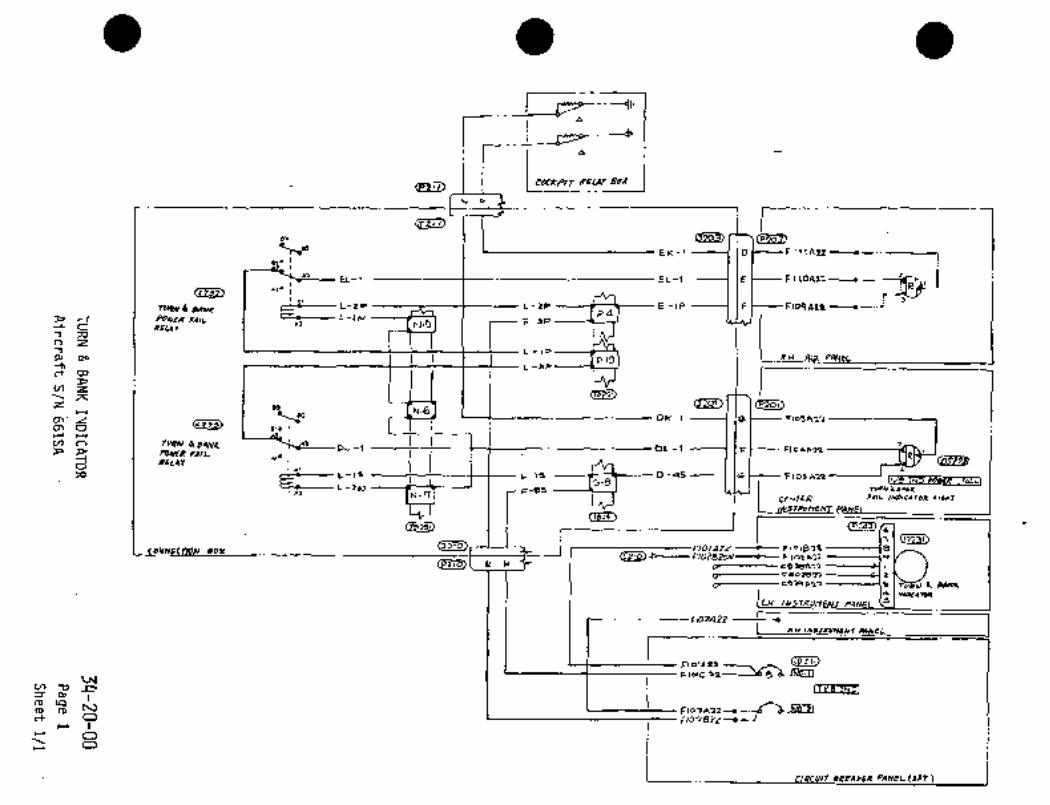
..C´•-"-~l i
ra ---~I´• I
r I a
IEU’Bb~ I
(pqlZ) I COC~-P/T R~
hi
02~L)
Ti7(prJo~EK-I 0 Frl!A22--´•--´•------1
iEL-1 E F11091~L’´•
N~4N 6; CINNX ~f----- L,ZP L-ZP E -1P --i--l I F FlOqC\ZP
A7u~p F~IL L-I~ F-3PP-d
OP zpoREUI
L-1D
P-IOAox.
Cn N-3
3, L-dP
(TBi~r~cR
cnzx
cp~ol,zH t~ DK-l
IV) O TYRN 6. BANI: DL-i DL-I F Flo4A1~FDMR ~AIL
A 1.-1’3 L-1S~-BS 0-45 Ic Flosa~IT/a rcco -~1IMR r~cl
0 psL41
L-31J
(r~lsl)
N-cl CeNmR FAIL I~NP(C*TOR L1611T
(re~
7)~BOY I
(Pllo~L U~
flOlLIZP FlolBse 8
(EZ~5)"p--Flollszov~-- F 162all s
c~--------- c~oaer,
L~---- CsW L9~2 1 a dPH~
S
IFIO?A 22
L RH
iFtornnz
FIPIC 91----~6 5 ~-´•lbW;nW
v, -c~ p I I I3 n,
n,ca
O F,o7szzrr, n, 10 Fto7AZI---´•
r
OO L
VI~ B~AIRR PAFICL (AFT
r
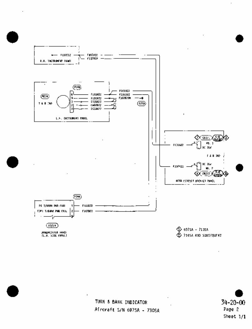
I
F107C22 F107A22
I R.H. INSTRUMENTPANELIF107D22
P249
8, F101B22
F101A22
F101D22M231
9 F102A22 F102B20N --~B
1 C538A22-13
2 C6O2822Tg8IND E210
3~------- C539A22
i
ICB271 CB
NO. 1
DC 28V
Tb8IND
~IOllP2 da3 DC 28VNO. 2i’C8272
I REAR CIRCUIT BREIKER PANEL
PI T/8ANK PWR FAIL Y~- F101D22
COPI T/8ANK PWR FAIL Z~-- F107D22
05219
O 697SA 713SAINNUIICIITOR PANEL
Q) 714SA AND SUBSE9UENTCL.H. STDE PANEL)
TURN BANK INDICATOR 34-20-00Aircraft S/N 697SA 730SA Page 2
Sheet 1/1

CHAPTER
PNEUMATIC
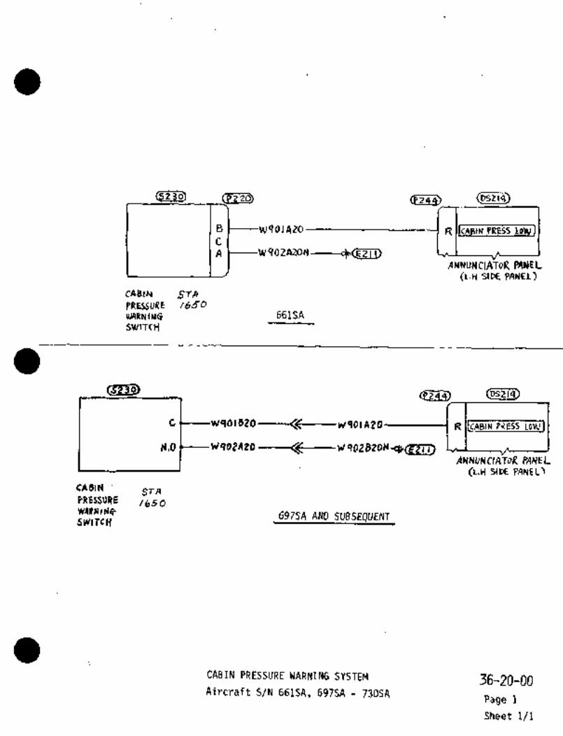
(P220)
BI W401AZo
i RJICABIN PRESS LODVJ
A ~----W ’10
ANNUNCIATOR PANE L
(L.H SIPE PANEL)
CAB(rV ST~
PRESSURE ib~O
uk9RN IL1G 661SA
SWITcH
~401820 ---~-----W901 AZO------------( Pi7ESS LoWI
VqoZA20 -----it--W qg~ BZDN
ANNUNCIATOR PANEL(L.C1 SltX PANEL)
CABINSTA
PRE~SURE /650W~IINld9 69fSA AND SUBSEOUENTS~k’lTcY
CABIN PRESSURE ´•WARNING SYSTEM .36-20-00Aircraft ´•S/N 661SA, 697SA 730SA
Page 1
Sheet 1/1

CHAPTER
VACUUM
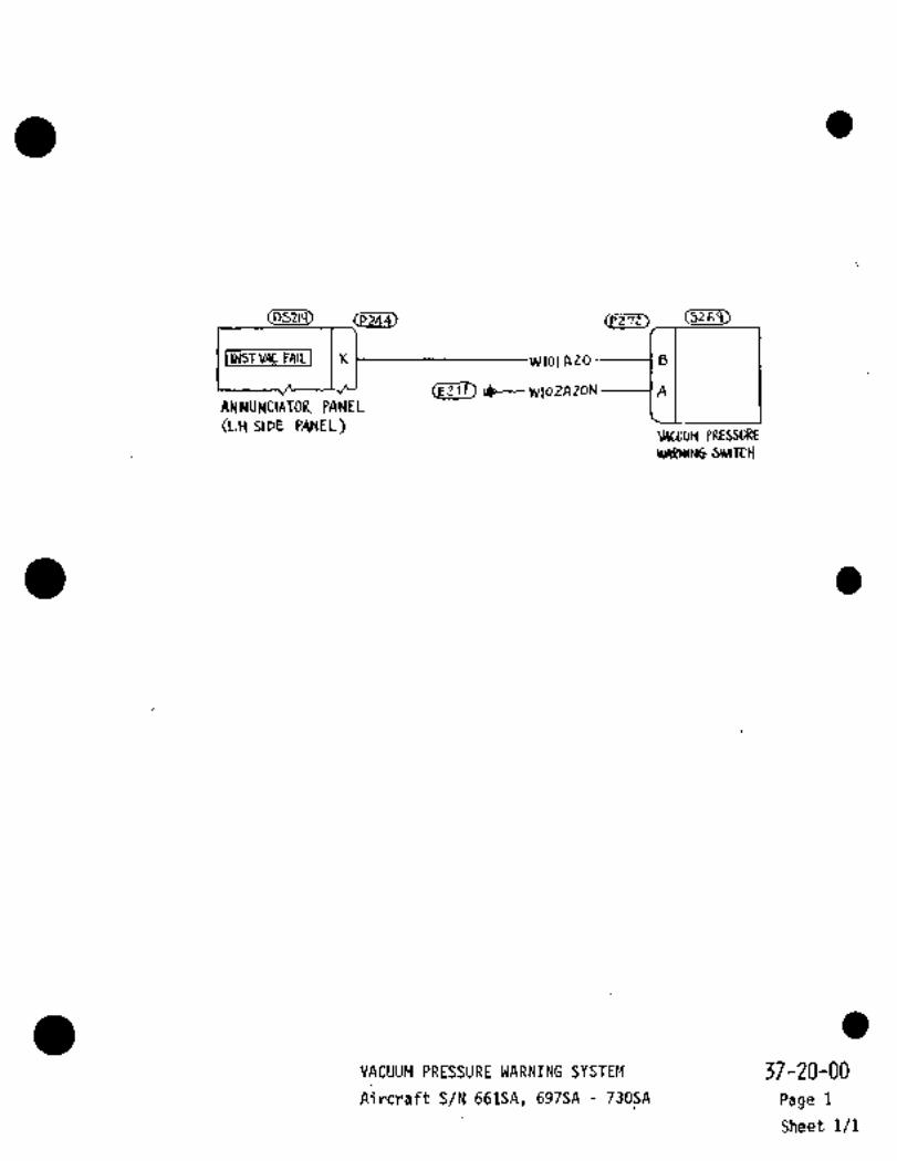
I INSI VAC TAI1J K w lot Azo -------1 B
Ilp--- IVloZA Zo~ AANNUNCIATOR PANEL~.H aoE PANEL)
wcuolj PRESSDREWARMII~ SWITT~
VACUUM PRESSURE WARNING SYSTEM ’37-20-00Aircraft S/N 661SA, 697SA 730SA Rage 1
Sheet 1/1

CHAPTER
DOORS

jSrA 5~0 50
(PRH LORD BUS
)oooR SEAIL~j3
----‘--7
C PZosl
CJ
C2~H401C?o---------1CD I ~--HLfolB?o
C/4
-X2
LAND´• GEAR SAFETYR~L;AY
M78 RELAY~ 80X__
~l.e 07
:F H402BZO-WN
P~´•O H403A20 Ha03820
DooR LOuc sw~TcH(STA 7250)
Doo~ SEAL ~VE(LI´•l. ~LECTRIC CIWPARnrENT)
O AIRCRAFT S/N 661SA, 697SA THRU 713SA
O AIRCRAFT S/N 714SA THRU 730SA
DOOR SEAL 52-10-00
Aircraft S/N 661SA, 697SA 730SA Page 1
Sheet 1/1

STA 3050
"C-
I r~Vr Dooa b~eN( Wu/gZ6 JI
~V.c.
PANc~L coN(d XO
ILH S/DE PANEL
~NTRAnlcG DD~R
LOCR SVYrrCI~
15TA 7250)
52-70-00
DOOR LOCK WARNING Page 1
Aircraft S/N´•661SA, 697SA 730SA Sheet 1/1

CHAPTER
PROPELLERS/
PROPU LSORS
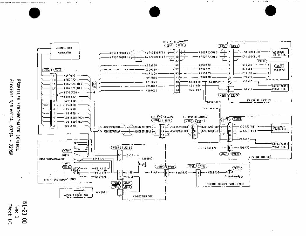
RH WING DISCONNECT
c~ (p~T)CONTROL BOX
:I K70A20(RED)----I GOVERNOR(WOODWARD) I ~---K251D20(RED) ;--i--~K251820(RED) 4 K251A2O(RED) CSPEED P.V.
K252020(8LU) ----c~-;--r K252820(8LU) 18 K252A20(BLU) ~I IU K71A20(BLU111 .1. 32 G +r ~2
K253820 50 K253A2O IB K72A2O ~---1 A (A414)
(5236) C~3 t K254820 --_1156 KZ54A20 E K73AZO I B ACTUATOR
K25582O --_--11 63 1--- K255A2O --------1(F t-- K74A2O ---t D
9 ~---K2578201(2568 20 --_----~1 71 K256A2O m K7 5A2O ----1 C
10 K267C20K258A2O V K92A2OK258CZO 80 K258B2O
11 t-KZ62E20(BLU)K257820 59 K257A20 BRUSH BLOCK
’El 12 K262D2O(BLU) K91A20 PHASE P.U.-sm K267CZ0 661- K267820 FP, r K256C20N
1 (P402O)
2 KZ41C20 RH ENGINE MACa~E Im‘ K256820;o
V, K268AZOV,
3 ~---K254820Z-<Z
4 -K253820QIOQI I 5 L KZ55BZOr;p
6 KZ51DZO(RED) STA 3050 CEILING LH WING DIS_CPNNECT
7 ~---KZ61D20(RED) (JPSf) (PZ57 IIV)O
PI~8 KZ58C20 K261CZO(RED) 77 1BEO(REDK261D2O(RED) jK261AZO(RED C K70A20(RE0) GOVERNORcSIV)
i IU K71AEOCBLU
u3 m SPEED P.U.K262CZ0(BLU) 79 BLUoP 16 G
V,
ZO v K92A207I BRUSH BLOCK
wV I Inno IPHRSE P.U. I I
SWITCH P G-1P (5427)~
~S234)
al~--E-4P
I~PROP SYNCHROPHASER K241D20 I Lf! ENGINE NACELLE__
_1
LIGHTP-15
/1~ K244A2O
1 ~bk----K241E20 F-5PK241B20-4~- K241A2O~h:
L CENTER INSTRUMENT PANELC--------------- K242A20Ib EK-3 I SYNCHROPHASER
CIRCUIT BREAKER PANEL (FWD)
I ~C----KZ42B20 T
I mcw!inilbrsoxI I
o,v, n C~3
Ivo
r oo

CHAPTER
ENGINE FUEL
AND CONTROL

rCP7~
IJzSR Cpl-~ ~l)o--L VII~OZA ZOY PC LJ 91A 2 O A
1 70~-- W j o I 5tt ----------------I pi C HlsbR la----(B
~’"’grV3MA228V5
(t+l~ FrUC~ PRhL~t+lZ
[f19e-
ini9FPMtO 17RA)JZ~17‘rLq
i Ir-24 i -20 2 bO -Ze at 472- 20--t- 4$9-20
I PH
3FP~zzor 4FP~i2
’Id aFCMi?~z -(H-h ;0 5F p.h" 21 c~
1 bP P~ L~ :C
1 FullP4~Y;NDV,V,C jSI ND
Z;Om
(3~w
250-20
409-30 ----t----447-10 I0FPWI20 IV,C3
O
ijC.jI1
--I
j~VACBFPINI 22 j W3Q3A21´• i Ilbt W303 BPP. \NsaA1 a
ii i i -1 8Bug
,1/´•-------- i P ~9/Aa o
L.lj, /v’clcE LEj
v, ~V3 P, WCDcPID rr, W
ro
rr
r O
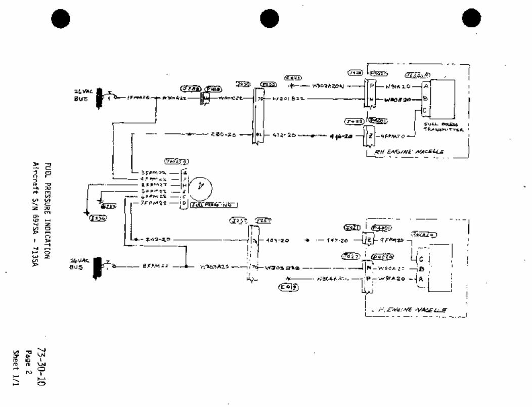
Tecp~
,,P~ u~ozA 20YI I PC-- \rl 91A 20
F~ese3
8VS wsoccZ~--f I f0t bJ 3 bl &22 )H Wg6R
T+22j(T+22)
~oo, PnEJJ
ebD-’loI le2i- 472- 20 4f~-20
1 ~t, j~i i. I C
1 m ----fe!3 4PP~iZ --JF(
eF ---)H
1_ i-
5F pn? 21ctmv, 6PPMLP C
V)V)
ZV, ACctD C7FPr/122DJ I FuU F4a~u :ND
m
(F~Zj "r"J>Z5~~J z
463-~i0 447-20jo
1~ I--I
rOi qe I1,´•~J w
iI
I j jWZV,
eFPM 22 W3Q3A22 II BPIL __IiBug N-W90A2D
C4~- It~----- -i P ;NTslA ao -7 8i i
i A
W C_i i
ii;
v, -oV
3 g, W~Dtpl
n, Wr~ O
h3
r O

IP2O1 P246 P242
IN-21 D-14N RI W307A22 E
M229
I N-3 -ID-15N B’ W308A22 ---IH0-2P IF+-- W3O3E22 ---(CDF-26 G W3O5C22 --tD(\ j FUELPRESS
D-3P --IlftW301E22 ’F IND
DJ-17 19 t~ W306C22 --~1GI I
CENIER I~JTRUMENT PRNEL )PANELI I
IDJ-17
(4452)P206 ,3255 P255 A452
J-8P 1W306822 W306A22 W9ZB20 W92A20 C
i5428
E424
~P--=--W302A20N i/P W91A20
W3O1C22 W301822 N W90A20
FUEL PRESSEFIGINE NACELLE (R.H.)TRANSMITTER
CENTER WING IL/E R.H.
II A452J21Q PZ10 5257 P257 5421
Oii. i iii~-- UIOI1IIi1"~ 110).11 --I~ YPilio Y(il2n it
(E419~E419
1~3- W304AZON -´•I I P W91A20 _--f A
F-22P i ICAC W303C22 ----1170t---- W303B22 -f IN~---- W90A20 18
FUEL PRESS
CENTEk WINGENGINE IL.H.)
i TRANSMITTER
L/E. L.H.
I -~--1F-21P -t Ii W303D22 W303A22
(08218)L.H. FUEL PRESS ´•IND.
400 HZ
F-Z3P rt- W301D2? wsoinz2h
R.H. FUEL PRESS IND. ICONNECTION BOX I I SIDE PANEL (LH) FWD 2:V AC I
I
O 714SA 717SA
Q 718SA AND SUBSEQUENT
iUT, PRI~ISURt INOIC~TIOII,~3,m
Airdraft´•S/N 714SA 730SA Page 3
Sheet 1/1

CHAPTER
ENGINE
CONTROLS

697SA- 730SA i
aH. ecT1
pcQ 661SA, 697SA 713SA
RdR6t tll)PIO---/ZI´• )--9)c-j
O 661SAL BrillRA ~t 2; 024-(1al I-0k-2
I L*,,, ~t LI.I 0 714SA 73051
661SA ONLY ~60 i (888
J-IHR;Q 1(110-~5 1(
pn rmucE IwOuTCP JK K
L~WT c----K1291;10--C---( 2 I 011-3 I le6~ 11 I
~r(-2145220
J I II I I I E-- D~-9
LW BETA 04445 114144262 DJ-e
LI(Tm 0)-7
PANR nmo~ 311-2 DJ-311204
I~po DJ-I
*J-.AFl3 n~-2
i 5u51tAvlD 20442 Ll1(lTSVI1WMaY~
I ~PAU-3I LW 21486 AYTD IllwtR umT 9*rlPI
I Ln kvllLn PHIEL IL(lvaM IiPBBD i ~D
Klowo ’el’ ~-SN ----C1 I I I ~D ~a;Dan~AGuvE 11120431 ir)~t:
dl Cn-2
JWTOY
10711’5000CH-2Cn-3
C 11-44 G-6P I ICC 1 411300
c.r /NF/N~ 31 0-40 1114700Gn-s lo~ie
JIAPllwm~y Crc-6 13016b G~-3 Cn-?
Crc-lO Cn-s
i Cn-5 an-,o Izow
Ci~lg)Gn-re 14230
s 411-1
P~S
00-4~n uAu(-nur-JTop ~ii UI Gn- 7
J*IAH y ,n-5
s-sJ-
4n-)I -0
61 Fn-5
F t~-6 S-6
LU CRAAII-IOUN-STOPJw,nn /I_ 4~-g
YI F11-2C~Z&l, ~4)
q~ ~n-4 F- rlPlu*u~un Icl n-lp
QPD Ln r P Fn-4 AF-llr(-2p F-13P
~H, 30. ´•L AF-18
BanrrmanramwrrC ,H-21 I I ’TT~ FFKn~0 Fn-3
QPI)7
Frl-Z-611 Fn-S 15
K 311-4 Fn;530~
L ~u,rcy~ART YLM F-
(J2 I I IICP 21 1)
P~mrAL ID"~Z 1
I F’k-4
a k’~P C9888c -3i RUmSIM6ln mTwr
~m
Lw ILI1Lt(E& rrr rPsrw 5
D sc~Ho
n-2PKc~W
J~-3L
1(2 d 3 C-SPc
11-10 EF-llP
k-ZP DF-UP 4-60
PANEL I-- 11-54 RELAY BoXUl,lbPSD
n-~Iln-blI
ENGINE PROPELLER CONTROL
~6-00-00Aircraft S/N 661SA, 697SA 730SA
Page 1
Sheet 1/5

ai~i010
~zsle2oK~20816 I I --I,, ra5tDZO
1(120C16 Ka5~C20K~OZt16 iK102ni611 I I I I I G---1(15aCa0 1(252870
K102C16(Ee~Pt,
""’0’8
K172020K175020 ~K175C20
K175J20
r--------------1 Isri is?o, I II I r---------~MJ5 CONTROLLER PINEL
RH LOAD BUB
K20183P K201*22
c~ I
ccai;o;e, K203822 NilBBa0 nllBJ20
IRn ’plG COPIII Ct~B)Ki72F20 K2o6P122 U8172620 K203P122 T
~8232)K10~*21 5
K205*22 M1(2(17821 L
K251C20 A
Ln Lone sus9* V(ILI*GE eEGUelTOP II
K252C20t~ 8
Ilels I
CONTROL RELAI
1(1(7820 1 *117*20~/&B161*20N C
K202A20N Y
ILn ENG CDNTIC~1BI) ~zsaaao
tlRCUm BRE*I(ER PI*IEL IFi(Ol J*173FZD
NL
K216A22 UK175520 K2213*22 i I
CtllLU 15K118*20 L~------ K215*22 ----1 N
K133820 1 ------1 L
OI~TL-- K161020 -~C1 ALH YOL~IGE REGUR*TORCONTROL RELAIl ~70 i Il
FcsTa 1020)
1(266820
L-___________l
eKlos*oCKZ~
Af
FM ST*RTEFI RELAIXI
XI
ieK137P.O
C~ULH SIPIRTER RELAY
X1
ST~ 3050
K1~1810------1331Kl~sn16 -----1 17 1 I--- Ki49E15K131n16 -------f 21 1 I(i3iJ16K139C20 ------12~ 1 K139820K1I5E16 -----)27 1Kf 75Ja0 --~--´•1 30 1 Ki75n20
I K215C22 17511 8210822
K261020 77 1 K261820K262D20 t-tke 1(262020 --+----------tcl 79 1 ~tL K262820KZB1E;LOicl I L---- K217022 ---H 40 1 ~t ~217822K261E20 t-c-I L-176
ENGINE Rr PROPELLER CONTROL AIRCRAFT S/N 66 LSA, 697SA 730SA
76-00-00
Changed Page27 AUG. 1999 Sheet 2/5

Im r*no DK
nossls g Iloclo
I Ii
j-! aDl~zo
KK
84E~J lc14K12~PX, 03
´•DI PIL 01
K1300)--f~FiCIC3KI?SIQP-=pL:CIn1756~A ss
~Am4urlLMnic~mll/et ´•BI gl´•~ (Bi
.~-nx’ A3RECAY
4rrl~_ul
17tJza
ia
KLQQCI6I6N/IILW ~UII
11~ azJIB,h187na, :*´•I ´•I
r~D LL----KI
_-L4 C6 s~mr
A~---C-/
*Is~ro ~C/NE1LZO
3,Rs~LAr ~cK,D6WO´•
~URPI(C.U/
n
~DIE
~B,RELAY 80X (D.C
r
~22)
L´•~*ne#a:
ENGIN~ PROPELLER CONTROL 76-00-00
Aircraft /N 661SA, 697SA i30SA Page I
Sheet 3/5
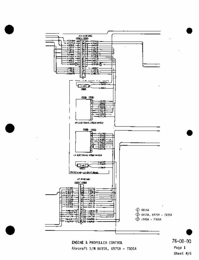
R.n ~DbC
4251530 -F~ 1(251420rz528a, d~--rnuuoKzolen~-flta
612664*124e 29~laW16 39
IIOBX)----H INH--nllo4m1(426
,4426
221n
rsi~
162326
--E166A12-----~
--E135AIZ---~121
RH
C~D ~3
KU
rla?AR---~
´•´•--E159AZZ--
cH bLELTRDhn Sl~iFOJmU/
~BBC;n~neai>
i
L~ v/MiD&
i Cp75a
Itlecp~e
Ib--~IUBn,
31(r~1(155CX1
UPA2OK145816-( ldl 41456 R)
n,1524 ~alcn,
O 661SA
Ilr O 661SA, 697SA 7135A6141 1126
rgls~Y 14 O 714SA 730SAr 1(t(a42P
ENGINE PROPELLER CONTROL 76-00-00
Aircraft S/N 661SA, 697SA 730SA Page 1
Sheet 4/5

Q 661SA
O 661SA, 697SA 713SA
O 714SA 730SA
CZCCPcI~f9, ~b wrcn
s~-´•-- Ecmo
PJL\Om~U,
K o
K KS~O
II,7424N-H ----l;r"--’~
424431 IC k70~ZOZPICDP ~L..--.JtZSZM, -~Cllu k7/nzDJsu"e IGUlnONU1IT QP~ C~b
9 ~B ~aP)
K(2IC 81 Ptr12itZo Q~7nfl--- js~nrropp r~PAEO
.K126aZaY k93A eo
I--(rb0~20 ------(v
1(94Cltpv~
K17k~ 11C´•´•-- oIL
(88) 3 ods~up Ill:I I LIL.._.~i P~mP
L----- 485 cZO
I L---Q84cg0----lal crs
L.. .-Y11:C’r-´• K’1I1ZD1-
E)4Am --´•´•-~*I
roaoucrwmnls~st´•- r7aazo la: J vAL18DC---´•-- 1(5a410 --´•-~´•-L-´•
jigL---ncn2~---- v----*621VO--´•´•Y-~r-11656814--1 II ~i_.._..J ,t
rK5TA8O
~E i
13120 11 rlD*ZD TV~BlrJIW\ZO~ ~695 Tt~p
----El?ra~ ---´•lol I~wPmMap-EldC~) -.1C:
611
Klscca, ---1 Ir 162681II 1(63PZD--´•-7g:
uz61AZO -~1IC A2a7PR~P ~L.._..J1262620 11 k7/arejsYhle 5TAlr FUSL PRH)U~ pEtiLRAfOR
9 (E3ID CIIB~
------E UAZD -7---E~onn ---~ei
nYAn, MICI~TKHIIQ RRrTOA I ~n,Q~9
OIL458679
1(176AZOll---H tn~---- 8: yLNT p~Pki i P
NTS--484crs
~(56A20hl Q85cZo PAZD-- v
i_-_..i~Ir--"60",2D 111*~-----P81
~sloz0 L 9826211 N~ CllM swW
k94tiZdC_,,,,, Iw~u
Lanwr 14198 a~ 81946
5 -´•~el ~LvO: D
14119684 lIIIT rco9AaD--- 11
QB~ L..-
EIUX)P~L 89956 LOU;QI~
C El~alo i~B)~i__..j
~nAZo
dJ*,lw3 t----- 1349
11 OOP~ZOW E( tAiZO
"p~e~YIRIEIZOBII#IDR_iE16(U)---
1F~H2 a4~ L.H EE#INE
ENGINE PROPELLER CONTROL 76-00-00
Aircraft S/N’661SA´•, 697SA 730SA Page 1
Sheet 5/5

CHAPTER
ENGINE
INDICATING

(JTT~)szl~
wza-Cn
Q 661SA, 697SA 713SA
IUOI_CL)L~C aLnL(6RN~EI~VA Q 714SA 730SA
O 718SA- 730SR
661SA, 697SA 7i4SA
rn (J´•~
(P)I~)
RHRUDLBZ-T~7 e \b 07 ~6
1400 12 4( 07- 15
A Er5?C22 id I IDF- 20
L.H
F~fnRi’
o -5N<n~B) F 5111429 Y
R~lrr YC, ellOC1? rl oF-ZI
/ND~4TDP An RVIL (G4EWJ
(a2P2) ;RII
D-6N
LHIT~ c E112 c 92 or-72
O
6
E1338e1328
caz~La) cp~je>n 313529 rlt-c~---DJ-5
XH 7RCHO- s Ei36C10 oj -b
,r o --4N
cCI~L)(P7i7~
A 6/39072 url DE-14
L.H 721C517- B EIPOCI~ Dr -10
MNFR c’ o -g~
Ero,BIQ q DF-~6
4 Elo3cPn r
O/L c tto~aPP ~e oJ-/2
(n_2Le)
P237
L.H~ P Elosem DF-17
14 5/07072 D~-/2Elo6~4ol I I
(i773n (PI~F)
EIQOC?s ,icJEIS~98n Or -24
*I~R
(n;~
HET59(5) rlg’7c22 ~´•I I
H LII~A 22 h I C--- D -lZN
O/LFKES( F EIIPE 22 3 1 C--- 0 53/N~ 0’ ’i DJ-14
(454 5_)081-----6191;4200 e~2?E21
elZBkn’2 IL DF-IS
~n430
Er06C22 ly/ t-------´• EF-2
E 190Ci2 E-?P
ix
i~/NSTRU~VT
i 77-00-00
ENGINE INSTRUMENT INDICATION PaE)e 11
Aircraft S/N 66ISA, 697SA 730SA Sheet 1/5

O 661SA, 697SA 722SA
730SA
"J /8 i 1’6~--- E1411g297- ,L E148312
07-5 \\6~---- F05B’12oJ-6
cJ -II Elo~ell151 Etozec’L
J-ZS 1 Iri?. 1DJ-14 ~B
D-/JN
0-,ZN -6N
o -r~v
D-4N
0-8N
c Ss 7-75 I5-3
-3S
0-&S ~F-dS5´•0
F-69 I rsa,s
J E190BLZ
F-(qP
jJ310~ ce´•~
DF-18F-as ----t \bF -tq P h -1 (ris~----EtSooaZF-2DP(5)----11r~--- E 190822oF-Lb ~---------1 Icll~----EtolnzeDF -171)7 -21 ----1
cF-22 i !CP~--EIIZBI?r -48 lq ~------C121n22F -Js -----------f Ir E119A22of-15 I (H"I tl06e21of -In I Ir, 21ole22.
IACI lt1498c1cF -lo ----------1DF -24 (eDF -25 I j I El9l8Z2EF-Z
~E´• -tJ 6199919CF;10 11~1 E15?B3PcF -i4 -1 IXI E158en4
77-00-00ENGINE INSTRUMENT INDICATION Page 1
Aircraft S/N 661SA, 697SA 730SA Sheet 2/5

O 661SA, 69jSA 713SA
714SA 730SA
718SA 730SA
661SA, 697SA 714SA
O 661SA,´• 697SA 722SA
723SR 73DSR
661SA
697SA 713SA
nrpeu i ID4~-- E 199e 22
CICOBI4 -----I In 5160922
~911I)~3
KELArEIagBn-----(
r
PMJB4I 22 --iP I I
I__
4:7BI
KI
lsoezys>~ D\E ~sacu----l 1?4~t+ 5 156822 EIJ~A 19
1
E184
I 142~ ~WW (olo Bu~
Q4158494 I 4
L I ~JA12 -6 5
xH---Eloscn Iwoan-----~ I ji~ ´•F [I-~uSTPTZlivTIWI
Els~ezz------l I JtK6)E(84422-I 4U~
~Jail14(1)7 -’U~
Rn411--1 CBlo)6
C,)ZblZI
Ltlos4n
NMAZ1 Clno?t
c~lpllr--l ~XSHIE1BB
77-0~-0(3ENGINE INSTRUMENT INDICATION Page 1Rev No 1
Aua 1/79 Airc~aft S/Fi ~661SA, 697SA 730SR Sheet 315

PO i 151~------E1075’15343 Elo,4?9
(ro~n
E13asal 1 )461 E136*~2 C~6133343~uce?l E~6C 1ACld~B?IErsal~ E*~2lE109g?l EtlOAseE150e~ EISOl\n~
S~-- 616,
EY18RH rc~wr
(EN~/NE XACELLE OPPE‘Zn ITTB fgRP~
~liO I
/--4wL(6*tW)B:44d
~I IE:31A 91 I I I u~v/7
:a43~
N33Aeq~
rt59cl; 192C1~3 9. U94n
nirL
Ie tQ/YIPP L)
L.H ITTB R2t
I EIPBPP1glP&qlll 10EipoB12
p~1448
rr!
LY
EN~NE NAG~LLE .UPPUI)
(F~5)
Elj6c~?6159333 ----------I a~
EICOeZZ lar(E~38Z1-------------Ir,53szl ----------I Isp~----prse*ias19183n 1 163, EEe2911 ’1 n)r---elOl
82n --E~epAoaElsacll
EADD~1Z 115~1EPnBoP I Isl~----- 1133933zllae~? --------------I IwC----ElzLCunalnsn -------1614933331976333196333 ~uoacp
Q 714SA 730SA
O 661SA L~HV,NODUC
~697SA- 713SA´•
r_
77-00-00ENGINE INSTRUMENT INDICATION
Page 1Aircraft S/N661SA, 697SA 730SA
Sheet 4/5

,~F’I´•20 (70422
102022
CI~ z.p 22 -------~1 I
B TEnp
r /~’J A/----RunLCGR) 1 )~r ICI~----CnRoM(wH) )\~----t171CH)-----10
(pqoI/)e Js 4 rz.
i (K ----1 e 7ACH
G4N
(J4"e)~ (P40U)BloLDZL.
E,o3A22--------------~ Ir\~-_rls´•le---l PI TEM P
(P402L)
E/20C22-------JI JS OILE/14C 22------( rLbnLo B
E/4~4 E/64~iLON 11 ~---fUAZo-----J A
~P 4097)
E193 A2Z(AIDI ----------------1 )G ~----EUAto-------( P
C14´•QAL1CB~ol I 020020 0 ~(IEL
r
(5-9~6)
p
c/Jsazz
L.~ CLEL~KL)N/C ZPE~
c~arm ~iwlrCy1, I
I -V- Lr_ W/hllj
7427 1
rr~inrrc.m) Eanlo RFurL
i I ~----Lf 20 420~-le FL~D W I I
0~4022)E/6bA201J (H E24At0--;;-1R 01~C149AEIL7t2’1 ’IR ~----etsAro----18 PRESS
/Zdc;U.1 i S 0 20420 ----i C
flo7~L1--------------------l O(I,
No6P22 7EM/3
(7421 )TC~Ela7AtZ-----------------l IWC--E/40r0---(2 -TPc~
22 IIXI "~oAzo---le 6#/3
cn~oNlwg----( ~URBI
Flon~ L~I) ----1 I K ~----E,6(RI) C 7En P
e/65 Plo6022B.
LH IENb NACELLE
II ElobEtoN
E´•121
77-00-00ENGINE INSTRUMENT INDICATION
Page 1
Aircraft S/N 661SA, 697SA 730SASheet 5/5