maintenance handbook on tap changer of ac …...camtech/2002/e/gr/1.0 maintenance handbook on tap...
TRANSCRIPT

CAMTECH/2002/E/GR/1.0
Maintenance Handbook on Tap changer of AC Electric locomotives March,2002
Maintenance Handbook on
Tap Changer of
AC Electric Locomotives
GOVERNMENT OF INDIA MINISTRY OF RAILWAYS
Centre for Advanced Maintenance TECHnology
CAMTECH/2002/E/GR/1.0
MARCH, 2002
Maharajpur, GWALIOR - 474 020

CAMTECH/2002/E/GR/1.0
Maintenance Handbook on Tap changer of AC Electric locomotives March,2002
2
FOREWORD
The proper maintenance of Tap Changer is necessary for trouble free operation of Electric Locomotive and to avoid failure enroute. CAMTECH has prepared this handbook to cover all essential aspects of maintenance of Tap Changer. The handbook describes various maintenance schedules along with their periodicity and detailed procedure to be adopted during repair and overhauling. A very useful compilation of list of common defects and their remedies is included in the handbook. The staff in maintenance depots will benefit from these, which in turn will be reflected in improved reliability and availability of Electric Locomotives and thus economy in operation.
CAMTECH, GWALIOR M.L.GUPTA 21ST MARCH, 2002 EXECUTIVE DIRECTOR

CAMTECH/2002/E/GR/1.0
Maintenance Handbook on Tap changer of AC Electric locomotives March,2002
3
PREFACE
The Tap Changer used in AC electric locomotives is vital equipment and its proper upkeep and maintenance is necessary to ensure reliability and availability of AC electric locomotives. This handbook on "Maintenance of Tap Changer " has been prepared by CAMTECH with the objective of making our maintenance personnel aware of correct maintenance and overhaul techniques to be adopted in field.
It is clarified that this handbook does not supersede any existing provision laid down in the “Maintenance manual of electric locomotive” or “AC traction manual” and instructions issued by Railway Board/ RDSO.
I am sincerely thankful to all officers and staff of electric loco directorate of RDSO/ LKO for their valuable comments. I am also thankful to all field personnel who helped us in preparing this handbook. Technological upgradation and learning is a continuous process. Hence feel free to write to us for any addition/ modification in this handbook or if you have any ideas. We shall highly appreciate your contribution in this direction.
CAMTECH, GWALIOR RANDHAWA SUHAG 20TH MARCH’ 2002 DIRECTOR
CAMTECH/2002/E/GR/1.0
Maintenance Handbook on Tap changer of AC Electric locomotives March,2002
4
FOREWORD v PREFACE vii
CONTENTS ix
CORRECTION SLIP xiii
Chapter 1 INTRODUCTION 1
1.1 The Selector Assembly 2
1.2 Circuit Breaker 5
1.3 Operating Principle of GR 6
1.4 Air Motor MG-2 with Control Unit 10
1.5 Operating Principle of SMGR 13
Chapter 2. MAINTENANCE 17
2.1 Periodic Schedules 17
2.2 Repairing/Overhauling of GR 24
2.3 Overhauling of SMGR 37
CONTENTS
CAMTECH/2002/E/GR/1.0
Maintenance Handbook on Tap changer of AC Electric locomotives March,2002
5
2.4 Check Sheet for Overhauling 49
Chapter 3 STICKING OF SMGR, CAUSES
AND SUGGESTIONS TO AVOID FAILURE
OF GR/SMGR 53
3.1 Sticking of SMGR 53
3.2 Suggestion to avoid Failures of GR/ SMGR 56
Annexure-A List of SMIs / MIS 60
Annexure -B List of Spares required For AOH/IOH 64
Annexure -C Kit of Standard Hardware for Tap Changer 70
References 81

CAMTECH/2002/E/GR/1.0
Maintenance Handbook on Tap changer of AC Electric locomotives March,2002
6
ISSUE OF CORRECTION SLIPS
The correction slips to be issued in future for this handbook will be numbered as follows: CAMTECH/2002/E/GR/C.S. # XX date----------- Where “XX” is the serial number of the concerned correction slip (starting from 01 onwards).
CORRECTION SLIPS ISSUED
Sr. No. Date of issue
Page no. and Item no. modified
Remarks

CAMTECH/2002/E/GR/1.0
Maintenance Handbook on Tap changer of AC Electric locomotives March,2002
CHAPTER 1
INTRODUCTION The single phase high voltage tap changer is used to notch the control winding on the high voltage side of the transformer up and down through 32 steps.
The tap changer is directly built on the transformer, the selectors and circuit breakers together form a constructional unit.
The circuit breaker is provided with magnetic blowout, and supported on two insulated columns . It is mounted on the oil filled selector casing.
Transformer and selector are separated by oil tight seals so that during overhauls only the oil from the selector casing need to be drained.
Tap changer is designed for higher service voltage (25 to 30 kV) and for high switching frequencies. This is equipped with a circulating pump and a filter for the selector oil. This device is intended to keep the selector oil clean over long periods of operations by extracting metallic particles, which may break off from the control gear.
Since two shaft extensions are available at the selector, the drive can be built on at the right-hand or left-hand end, depending on the space available.

CAMTECH/2002/E/GR/1.0
Maintenance Handbook on Tap changer of AC Electric locomotives March,2002
2
1.1 THE SELECTOR ASSEMBLY
The selector assembly consists of following components: Item Description
11 Base frames with covers
12 Contact plate with connecting pins
13 Selector housing with covers
14 Drive shaft with gearing
15 Notching wheel with contact arm
16 Bushing and contact rings
19 Components for fitting air-motor and Cowling
FIGURE 1.1 SELECTOR ASSEMBLY
16 13 12 16
15 14
14 11

CAMTECH/2002/E/GR/1.0
Maintenance Handbook on Tap changer of AC Electric locomotives March,2002
3
FIGURE 1.2 SELECTOR FRONT VIEW

CAMTECH/2002/E/GR/1.0
Maintenance Handbook on Tap changer of AC Electric locomotives March,2002
4
Details of figure 1.2 Item Description Item Description 11 Base frame complete. 14 Driving shaft with
gearing 1101 Base frame 1401 Driving shaft 1102 Sealing ring 1416 Gearing insert complete. 1103 Base cover 15 Stepping wheel with
contact arm 1104 Drain plug 1521 Distance tube 1105 gasket 1522 Circlip 1108 Hexagonal bolt 16 Bushing and contact rings 1109 Spring washer 1601 Bushing, double pole 1110 Cover plate (upper) 1602 Hexagonal bolt 1111 Hexagonal bolt 1603 Spring washer 1112 Spring washer 1607 Carrier plate with guide
sleeve 12 Contact plate complete 1608 Contact ring, inner 1201 Contact plate 1609 Contact ring, outer 1202 Sealing ring 1613 Hexagonal bolt 1203 Hexagonal bolt 1614 Spring washer 1204 Spring washer 1615 Circlip 1205 Potential contact 21 Support with circuit
breaker 1208 Contact pin, inner 2101 Support, left 1209 Contact outer 2132 Support, right 13 Selector housing
with cover
1301 Selector housing 1305 Spring washer 1302 Cover 1311 Oil-drain connection 1303 Gasket 1314 Drain plug 1304 Hexagonal bolt

CAMTECH/2002/E/GR/1.0
Maintenance Handbook on Tap changer of AC Electric locomotives March,2002
5
1.2 CIRCUIT BREAKER
Details of Figure 1.3 Item Description 21 Support with breaker
frame 22 Breaker shaft 23 Switching element 24 Magnetic core with
blowout coil 25 Arcing chamber
FIGURE 1.3 CIRCUIT BREAKER ASSEMBLY
25 24 21
21 23 22

CAMTECH/2002/E/GR/1.0
Maintenance Handbook on Tap changer of AC Electric locomotives March,2002
6
1.3 OPERATING PRINCIPLE OF GR
The moving contact rollers K1 and K2 in the selector actuate with the current cut off. Before a roller leaves the fixed contact, the relevant circuit is interrupted by the associated circuit breaker. The connections of the tap changer in the high voltage circuit of the transformer are shown in figure 1.4 and sequence of movements of the selector and of the circuit breaker contacts is shown in fig. 1.5.
FIGURE 1.4 CONNECTION OF TAP CHANGER
TO THE TRANSFORMER
MSW
23°-I 23-II 23-III
R1
R2
32
31
30
29 RW
4
3
2
1 0
M SW
1215
1608 1515-I K1 15
1216
1609 1515-II K2

CAMTECH/2002/E/GR/1.0
Maintenance Handbook on Tap changer of AC Electric locomotives March,2002
7
When changing over, the resistor R1 carries the current for a short time together with a circulating current produced by the tapping winding about to be switched in or out.
The high-value resistor R2 serves as the
connection between equal potentials, which ensures that the branches of the circuit being interrupted at the given potential. The making angles of the contact, as the angle of rotation of the selector drive shaft, must remain within a tolerance of ± 3°.
While the rollers remain at the segments 1 and 0, the breaker I close and take over the service current. A circulating current then flows through the resistor R1 produced by the tapping winding 0-1 until the breaker II opens. Finally the disconnected contact roller runs off segment 0. The tap changer is now at step 1.
The critical angles (referred to the drive shaft) between the switching sequences at the circuit breakers and in the selector are designated with the letters x and y. Deviations in accordance with tolerances indicated must be taken into account. The maximum permissible rotational speed at the drive shaft can be determined from the values of these angles (quoted for new contacts) and form the time taken for the arc to quench during and interruption. As the arcing tips of the breaker contacts piece wear the critical angles and thus also the safety margins increase. The mechanical method for achieving the intermittent switching movement is shown in fig.1.6.

CAMTECH/2002/E/GR/1.0
Maintenance Handbook on Tap changer of AC Electric locomotives March,2002
8

CAMTECH/2002/E/GR/1.0
Maintenance Handbook on Tap changer of AC Electric locomotives March,2002
9
FIGURE 1.6 INTERMITTENT SWITCHING
MOVEMENT
CAMTECH/2002/E/GR/1.0
Maintenance Handbook on Tap changer of AC Electric locomotives March,2002
10
1.4 AIR MOTOR MG-2 WITH CONTROL UNIT
The motor is of the four cylinder-reciprocating type is used to drive tap changer. A pressure reducing valve, a three- way cock and a pressure gauge to read between 0 and 10 kg/cm2 are connected in series with the motor. It is advisable to couple a two pole auxiliary switch with this three-way cock so that when the latter is closed, the control leads are switched off at the same time. The electrically operated pneumatic control unit is connected to the air motor by two connections and one return line. Depending on the pulses received this unit allows the motor to run in steps or continuously in either direction.
Facilities are provided for incorporating one or
several drums for control, indicating and interlock contacts. The air motor and its control unit is virtually unaffected by temperature changes, moist air, shock and vibration. The motor is provided with an enclosure to protect it against dust etc. The air motor and control unit is shown in figure 1.7 and figure 1.8 respectively.
CAMTECH/2002/E/GR/1.0
Maintenance Handbook on Tap changer of AC Electric locomotives March,2002
11
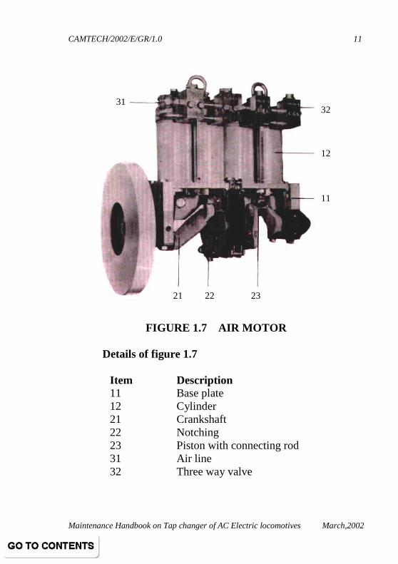
FIGURE 1.7 AIR MOTOR
Details of figure 1.7
Item Description 11 Base plate 12 Cylinder 21 Crankshaft 22 Notching 23 Piston with connecting rod 31 Air line 32 Three way valve
32 12 11
31
21 22 23

CAMTECH/2002/E/GR/1.0
Maintenance Handbook on Tap changer of AC Electric locomotives March,2002
12
Details of figure 1.8
Item Description Item Description
41 Control block 52 Planetary gearing
42 Three way valve 53 Valve push rod
43 Operating solenoid 54 Stop
44 Control cylinder 55 Auxiliary switch drum
45 Control lever 61 Gearing
51 Camshaft 62 Counter
FIGURE 1.8 CONTROL UNIT
53 62 51 54 55
44
45
52 51
43 42 41
CAMTECH/2002/E/GR/1.0
Maintenance Handbook on Tap changer of AC Electric locomotives March,2002
13
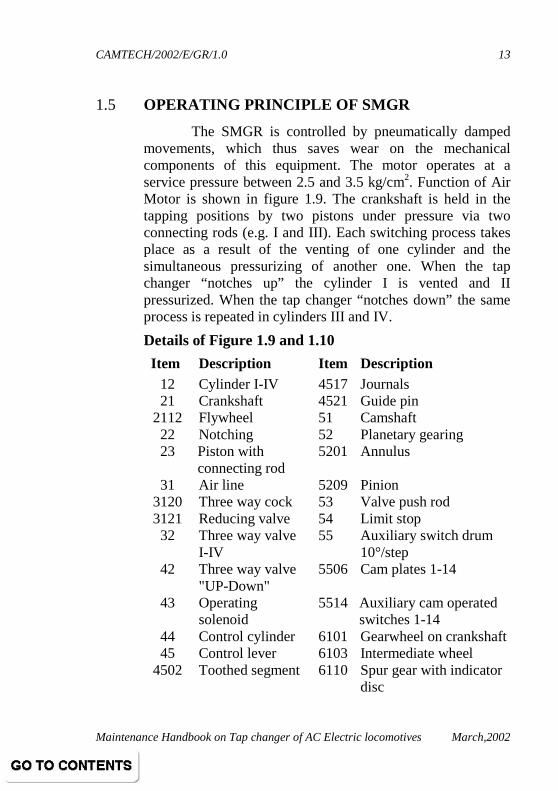
1.5 OPERATING PRINCIPLE OF SMGR
The SMGR is controlled by pneumatically damped movements, which thus saves wear on the mechanical components of this equipment. The motor operates at a service pressure between 2.5 and 3.5 kg/cm2. Function of Air Motor is shown in figure 1.9. The crankshaft is held in the tapping positions by two pistons under pressure via two connecting rods (e.g. I and III). Each switching process takes place as a result of the venting of one cylinder and the simultaneous pressurizing of another one. When the tap changer “notches up” the cylinder I is vented and II pressurized. When the tap changer “notches down” the same process is repeated in cylinders III and IV.
Details of Figure 1.9 and 1.10
Item Description Item Description 12 Cylinder I-IV 4517 Journals 21 Crankshaft 4521 Guide pin
2112 Flywheel 51 Camshaft 22 Notching 52 Planetary gearing 23 Piston with
connecting rod 5201 Annulus
31 Air line 5209 Pinion 3120 Three way cock 53 Valve push rod 3121 Reducing valve 54 Limit stop 32 Three way valve
I-IV 55 Auxiliary switch drum
10°/step 42 Three way valve
"UP-Down" 5506 Cam plates 1-14
43 Operating solenoid
5514 Auxiliary cam operated switches 1-14
44 Control cylinder 6101 Gearwheel on crankshaft 45 Control lever 6103 Intermediate wheel
4502 Toothed segment 6110 Spur gear with indicator disc

CAMTECH/2002/E/GR/1.0
Maintenance Handbook on Tap changer of AC Electric locomotives March,2002
14
FIGURE 1.9 FUNCTION OF AIR MOTOR

CAMTECH/2002/E/GR/1.0
Maintenance Handbook on Tap changer of AC Electric locomotives March,2002
15

CAMTECH/2002/E/GR/1.0
Maintenance Handbook on Tap changer of AC Electric locomotives March,2002
16
Cyclic distribution (determined by control pulses) over the four cylinders enables any sequences of switching steps in either direction. The notching holds the motor at the tapings when no air pressure is available; this also ensures that the crankshaft stops in the correct position. Function of control unit is shown in figure 1.10.
The control unit is designed so that each step of the
driven unit corresponds to two switching steps of 90° each at the crankshaft. The control pulses to the cylinders are initiated by the three way valves, which in turn are operated by camshaft. The camshaft is coupled to the crankshaft through gearing (ratio 1:1). The intermediate planetary gearing can reset the position of the camshaft with respect to the crankshaft so that the valve positions are changed over for running in notching up or down. The motor rotates in the clockwise or counter clockwise direction. External control commands act upon the solenoid valves and are transmitted to the control cylinder as pressure pulses. This causes the lever arm with the toothed segment to rotate about the pivot either towards the right (notching up) or to the left (notching down). The toothed segment engages with the pinion, which carries the axis of the planet wheel. When the annulus is stationary, movement of the planet wheel causes the camshaft to rotate in one or the other direction by 75° (lead angle). This involves a displacement relative to the crankshaft, which is maintained as long as the control command persists. Short control commands are continued mechanically so that the motor can complete one entire tap change. The guide pin on the swung out control lever then runs over a cam on the gearwheel. A mechanical interlock prevents overrunning the limit position when the operating mechanism is actuated by hand.

CAMTECH/2002/E/GR/1.0
Maintenance Handbook on Tap changer of AC Electric locomotives March,2002
17
CHAPTER 2
MAINTENANCE 2.1 PERIODIC SCHEDULES
The activities to be carried out during various periodic schedules are as under: Indication: "*" work to be done, "-" Work not to be done
S.N SCHEDULE ACTIVITIES IA
IB
IC
AOH
IOH
SMGR
1. Carry out general inspection and cleaning * * * * *
2. Check tightness of connections * * * * *
3. Overhaul SMGR - - - * *
4. Examine all auxiliary contacts for cracks, carbonisation, tightness of all connections. If required, replace by nylon auxiliary switch.
- - * * *
5. Clean all auxiliary contacts. - - * * *
6. Check and lubricate all the gears and other parts.
- - * * *
7. Check all drive parts visually for any abnormality.
- - * - -
8. Overhaul control block. - - * * *

CAMTECH/2002/E/GR/1.0
Maintenance Handbook on Tap changer of AC Electric locomotives March,2002
18
S.N SCHEDULE ACTIVITIES IA
IB
IC
AOH
IOH
9. Check proper clamping and strengthening of ZSMGR panel.
- - * * *
10. Check smooth operation of ZSMS - - * * *
11. Ensure locking of SMGR foundation bolts by plate or lock nut.
- - * * *
12. Check notching spring, selector lever bolt SMGR foundation for any cracks.
- - * - -
13. Check connection tightness of SB and foundation bolts.
- - * - -
14. Die penetrant test on crankshaft, SMGR support bolt and notching spring.
- - - * *
15. Ensure 100% replacement of " Must change items".
- - - * *
16. Leakage testing of SMGR. - - - * *
17. Load testing of SMGR along with GR and CGR on test panel.
- - - * *
18. Paralleling of SMGR auxiliary cam switches with spare one.
- - * * *
19. Check SMGR crank shaft alignment during overhauling as per Adtranz Jigs and Fixture.
- - - * *

CAMTECH/2002/E/GR/1.0
Maintenance Handbook on Tap changer of AC Electric locomotives March,2002
19
S.N SCHEDULE ACTIVITIES IA
IB
IC
AOH
IOH
20. Modification to connection lever of SMGR for tap changer to avoid air leakage RDSO/WAM4/58.
- - - * *
21. Modification to control lever of SMGR for tap changer - RDSO/WAM4/117.
- - - * *
22. Application of loctite between the mating surface of cams shafts and grub screw and tap holes of tap changer - RDSO/WAM4/145.
- - - * *
23. Ensure provision of ceramic filter. - - - * *
TAP CHANGER
1. Check condition of RGR and RPGR * * * * *
2. Check oil level if less, add up to 40 ° C * * * * *
3. Check colour of silica gel and replace/ recondition if necessary.
* * * * *
4. Check connection of double pole bushing to CGR1 and 3.
* * * * *
5. RGR (Other than Lacchman make) IR valve to be checked (with 1000 V megger. (Min - 19 MΩ)
* * * * *
6. Check BDV of oil as per IS: 6772 - - * * *
7. Check condition of selector (In 2nd IC) - - * * *
8. Check tangential play in moving contact (2nd IC)
- - * * *

CAMTECH/2002/E/GR/1.0
Maintenance Handbook on Tap changer of AC Electric locomotives March,2002
20
S.N SCHEDULE ACTIVITIES IA
IB
IC
AOH
IOH
9. Check DGA, if acetylene contents are more than 3 PPM then open the GR cover and check.
- - * * *
10 GR oil flushing to be done if due. - - * * *
11 Check for any oil leakage. * * * * *
12 Drain the oil and remove the cover. Clean with jet and nylon brush.
- - - * *
13 Check angle setting and contact shorting - - - * *
14 Check RPGR value and condition. - - - * *
15 Replace all gaskets - - - * *
16 Check safety valves and manual drive for proper functioning. Overhaul safety valve.
- - - * *
17 Replace top and bottom oil seal. - - - - *
18 Maintenance of Tap changer by set of jigs and fixtures and special tools of M/s Adtranz only.
- - - * *
19. Fastening RGR and CGR support plates on Tap changer assembly RDSO/WAM4/ 52
- - - * *
20 Modified flexible connection between RGR & GR - RDSO/WAM4/136.
* * * * *
21 Provision of canopy on safety valves of Tap changer RDSO/WAM4/187.
* * * * *

CAMTECH/2002/E/GR/1.0
Maintenance Handbook on Tap changer of AC Electric locomotives March,2002
21
S.N SCHEDULE ACTIVITIES IA
IB
IC
AOH
IOH
22 Permanent connection of 16th Tap in place of spring loaded connection. RDSO/WAM4/192.
- - - * *
23. Replacement of insulating oil & Silica gel of Air drier of GR.
- - - * *
24. 100%Replacement of "Must change items" - - - * *
25. Check working of safety valves whenever GR cover open/ canopy provided
* * * * *
26. Overhaul - - - * *
CGR
1. Check Arc Chute for flash mark, crackness and ensure intactness of latches.
* * * - -
2. Measure contact pieces dimensions. Replace if less than 36 mm.
* * * * -
3. Lubricate mechanical joints/ pins of CGR assembly.
- - * * *
4. Check CGR sequence through MOM. - * * * *
5. Check CGR to RGR and CGR1 to A34 connection. it shall not be close to foundation.
* * * * *
6. Check tightness of contact screw and foundation screw.
* * * * *
CAMTECH/2002/E/GR/1.0
Maintenance Handbook on Tap changer of AC Electric locomotives March,2002
22
S.N SCHEDULE ACTIVITIES IA
IB
IC
AOH
IOH
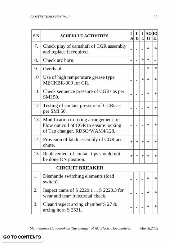
7. Check play of camshaft of CGR assembly and replace if required.
- - - * *
8. Check arc horn. - - * * -
9. Overhaul. - - - * *
10 Use of high temperature grease type MECKBR-300 for GR.
- - * * *
11 Check sequence pressure of CGRs as per SMI 50.
- - - * *
12 Testing of contact pressure of CGRs as per SMI 50.
- - - * *
13 Modification to fixing arrangement for blow out coil of CGR to ensure locking of Tap changer. RDSO/WAM4/128.
- - - * *
14 Provision of latch assembly of CGR arc chute.
* * * * *
15 Replacement of contact tips should not be done ON position.
* * * * *
CIRCUIT BREAKER
1. Dismantle switching elements (load switch)
- - - * *
2. Inspect cams of S 2220.1 ... S 2220.3 for wear and tear/ functional check.
- - - * *
3. Clean/inspect arcing chamber S 27 & arcing horn S 2531.
- - - * *

CAMTECH/2002/E/GR/1.0
Maintenance Handbook on Tap changer of AC Electric locomotives March,2002
23
S.N SCHEDULE ACTIVITIES IA
IB
IC
AOH
IOH
4. Inspect/replace CGR contacts S 2529 and S 2530. Tighten Allen bolts with 2.5 Kg- meter torque.
- - - * *
5. Clean switching elements and carry out functional checks with the use of special tools.
- - - * *
6. Lubricate contact pivot (S2528) with high temperature grease.
- - - * *
7. Tighten Allen key bolts M6, M8 & M12 with torque wrench.
- - - * *
PHGR
1. Check the working of PHGR * * * * *
2. Check visually for any leakage. * * * - -
3. Tightness of pipe line clamp as per RDSO/MODI/114.
* * * * *
4. Overhaul PHGR and replace rubber items.
- - - * *
5. Filter cleaning to be done. - - * - -
6. Attend the booking if any. * * * - -
7. Provision of modified PHGR. * * * * *
8. Ensure support for oil flow indicator as per RDSO/MODI/162.
* * * * *

CAMTECH/2002/E/GR/1.0
Maintenance Handbook on Tap changer of AC Electric locomotives March,2002
24
S.N SCHEDULE ACTIVITIES IA
IB
IC
AOH
IOH
RGR
1. Inspect elements for overheating/cracking.
- - * * *
2. Inspect insulators for cracks. - - - * *
3. Carry out meggar test and measure resistance value.
- - - * *
4. After overhauling, carry out tests as described and record.
- - - * *
2.2 REPAIRING/ OVERHAULING OF "GR"
2.2.1 Removal of Contact Arm • Lift contact rollers, place hexagonal key and turn
through 90°. • Remove bolts at bushing and circlip, lift out carrier
plate contact rings. • Remove circlip and distance tube. Lift out contact
arm with stepping wheel.
2.2.2 Removal of Roller Contacts
Turn roller-lifting gear at bolt to position "On" with key. Undo lacing and push out insulated tube. Withdraw outer contact-roller casing (hold roller with thumb), whereupon contact roller with bearings, roller guide and pressure springs are now free to drop out. Remove bolts and push out insulated tube to withdraw inner contact rollers with contact housing. The fixed and moving insulation in the selector can now be cleaned.

CAMTECH/2002/E/GR/1.0
Maintenance Handbook on Tap changer of AC Electric locomotives March,2002
25
2.2.2.1 Check for wear
If the tracks on the segments and rails are deeper than 0.5mm, these parts have to be renewed. The contact rollers are allowed to wear to a minimum diameter of 17 mm; contact rollers with smaller diameters have to be changed. When the rollers run correctly, the contact surface on the segments, rings and contact rollers should be polished bright.
Check roller guide and bearing for wear renew as necessary. The roller guide must move freely in the housing.
2.2.2.2 Refitting contact arm
Before fitting the complete roller housing on the table plate, ensure that rollers turn easily under pressure of spring during backward and forward movements. For the lacing, use good quality hemp string (1 to 2 mm thick). Before fitting the complete contact arm with stepping wheel, lift rollers when fitted set "0" position with checking pin.
2.2.3 Removal and dismantling of gearing
• Remove 3 bolts and withdraw gearing plate with bearing journal. Do not remove 6 bolts since will this release oil from transformer.
• Remove threaded pin, circlip and pull out distance tube.
• Make a note of the number at shims position during removal of drive wheel so that the original settings can be retained during reassembly.

CAMTECH/2002/E/GR/1.0
Maintenance Handbook on Tap changer of AC Electric locomotives March,2002
26
• The actuating pins are hardened (HRc 58 ± 4). • Renew lantern gear pinion when rollers are
considerably worn. Minimum permissible diameter 15.5 mm. When refitting the reassembled gearing the wheels should be set to a tapping position with the aid of the checking pin.
2.2.4 Work on the Selector, which involves draining of Transformer
• Remove contact pins and renew gaskets.
• Open up side possibly also base covers.
• Loosen connecting terminal.
• Remove special nut in the contact plate (front) and withdraw pin in direction of terminal.
• Hold connecting terminal with spanner during loosening or tightening of clamping nuts.
2.2.4.1 Removal of Bearing Flange
• Remove the horizontal shaft first. Remove driving mechanism.
• Expose shaft extension; i.e. remove gear wheel and setting device.
• Remove circlips on both sides. • Unhold journal bearing and withdraw. • Pull out shaft the right. Remove bolts at bearing
flange and withdraw this flange together with bevel wheel and coupling tube.

CAMTECH/2002/E/GR/1.0
Maintenance Handbook on Tap changer of AC Electric locomotives March,2002
27
2.2.4.2 Dismantling of Bearing Flange
• Knock out securing pin, pull out coupling pins and coupling tube. Release tab washers and withdraw bevel gear with shaft and ball bearings.
• Note number of shims. These shims must be positioned before refitting of ball bearings.
• During removal and refitting of coupling shaft ensure that the feather edge of the sealing ring is not damaged.
• During renewed of this deal it should be reinserted with a tube or ring 50/57 mm in diameter.
• Remove bevel wheel with shaft.
• Remove contact arm and gearing.
• Take off lock nut and remove threaded pin.
• Remove bevel wheel with shaft and ball bearing in a downward direction. If the sealing ring has to be taken out of this bearing, the upper bearing flange requires removal.

CAMTECH/2002/E/GR/1.0
Maintenance Handbook on Tap changer of AC Electric locomotives March,2002
28
2.2.5 Work on Circuit Breaker
2.2.5.1 Removal of Switching Element
• Remove arcing chamber
• Set tap changer so that the rollers upper and lower are loose. Lift off switching element with insulated rail.
• When refitting element ensure that the insulated bar does not become wedged between the connecting plates and the mating contacts.
• When refitting the contact lever care must be taken that the individual washers, i.e. plain washer, dished washer and plain washer, are correctly located. Ensure that the pin washers are not mixed up since these are used as shims of varying thickness.
• Renew worn out arc horns. Maintain 0.5 to 1 mm clearance between contact and arc horn.
• Clean insulated parts with dry, clean rag.

CAMTECH/2002/E/GR/1.0
Maintenance Handbook on Tap changer of AC Electric locomotives March,2002
29
2.2.5.2 Removal of Circuit Breaker Shaft
Details of circuit breaker and camshaft assembly are shown in figure 2.1 and figure 2.2 respectively.
FIGURE 2.1 CIRCUIT BREAKER ASSEMBLY

CAMTECH/2002/E/GR/1.0
Maintenance Handbook on Tap changer of AC Electric locomotives March,2002
30
Details of figure 2.1
Item Description Item Description
1316 Rating plate 2122 Hood
1401 Drive shaft 2123 Hexagonal bolt
1601 Double pole Bushing 2124 Spring washer
1602 Hexagonal bolt 2125 Threaded pin
1603 Spring washer 2126 Hexagonal nut
1604 Connection 2127 Spring washer
1605 Hexagonal bolt 2128 Hexagonal bolt
1606 Spring washer 2129 Hexagonal nut
1607 Carrier plate with guide sleeve
2130 Tab washer
1608 Contact ring inner 2131 Insulated plate, lower
1609 Contact ring outer 2132 Support, right
1620 Hexagonal bolt 2133 Hexagonal bolt
1611 Spring washer 2134 Spring washer
1612 Washer 2135 Connecting angle
1613 Hexagonal bolt 2136 Wire connection
1614 Spring washer 2137 Hexagonal bolt with nut
2101 Support left 2138 Spring washer
2102 Coupling shaft 2139 Connecting link
2103 Bevel wheel 2140 Resistor R2

CAMTECH/2002/E/GR/1.0
Maintenance Handbook on Tap changer of AC Electric locomotives March,2002
31
Item Description Item Description
2104 Securing pin 2142 Hexagonal bolt
2105 Centering 2143 Cap nut
2106 Dust cover 2144 Hexagonal bolt
2107 Clamp 2145 Washer (soft copper)
2108 Self aligning ball bearing
2146 Contact bolt
2109 Bevel wheel 2147 Contact nut
2110 Securing pin 2148 Hexagonal bolt
2111 Circlip 2149 Spring washer
2112 Lifting link 2150 Connection
2113 Bearing plate, left 2151 Contact bolt
2114 Insulated plate, upper 2152 Contact nut
2115 Connection bar 2153 Spring washer
2116 Hexagonal bolt 2154 Hexagonal bolt
2117 Spring washer 2155 Spring washer
2118 Bearing plate, right 2156 Hexagonal nut
2119 Hexagonal bolt 2157 Connection
2120 Spring washer 2158 Hexagonal bolt
2121 Hexagonal nut 22 Camshaft
2141 Insulated sleeve 2209 Bevel wheel

CAMTECH/2002/E/GR/1.0
Maintenance Handbook on Tap changer of AC Electric locomotives March,2002
32
• Remove connections between capacitor bushing and circuit breakers.
• Remove bolts and threaded pin at terminal clamps. Lift breaker frame from the carrying links.
• Unscrew bearing plate on the right and take off bolts on top and bottom.
• Remove circlip and withdraw ball bearing as well as cam plates.
FIGURE 2.2 CAM SHAFT ASSEMBLY
Details of figure 2.2
Item Description Item Description
2111 Circlip 2206 Ball bearing
2201 Cam plate I 2207 Circlip
2202 Cam plate II 2208 Shim
2203 Cam plate III 2209 Bevel wheel
2204 Shaft 2210 Securing pin
2205 Circlip 2211 Circlip

CAMTECH/2002/E/GR/1.0
Maintenance Handbook on Tap changer of AC Electric locomotives March,2002
33
• Ensure shims are correctly fitted.
• Now to remove coupling shaft, lift off support and remove base bolts.
• Knock out pin at upper bevel wheel. Withdraw bevel wheel and withdraw coupling shaft downwards. During refitting ensure that the dust cover is positioned between bevel wheel and ball bearing.
2.2.6 Mounting Tap Changer on the intermediate reservoir
This is sealed from the transformer with an insulated plate, the bushings having to be oil tight as well. The reservoir is filled through a connecting pipe to the transformer, in which a stopcock has to be fitted, which can be closed when draining the intermediate reservoir. A vent valve is provided at the highest point of the reservoir, which remains open during filling until the oil overflows. The reservoir can be emptied through a drain cock.
The electrical leads are equipped with plugs, which can easily be connected with the terminal pins on the selector.
2.2.6.1 Procedure
• Remove base and side covers also cover plate on selector frame.
• Lightly and uniformly coat gasket between selector and transformer with a paste prepared from talcum powder and a little vaseline to prevent the gasket sticking to the metallic parts.

CAMTECH/2002/E/GR/1.0
Maintenance Handbook on Tap changer of AC Electric locomotives March,2002
34
• Tighten nuts in the selector frame uniformly.
• At least two, preferably four spring washers should be placed under the nuts to avoid leakage.
• The plugs of the connecting leads are now fitted in a straight line to the contact pins of the selector. Push home connects terminals as far as body of plug. Hold with open-ended spanner and tighten clamping nuts.
• First make connections for the inner circle and check them. Fit all covers.
• After filling transformer and intermediate reservoir, check for leaks.
2.2.6.2 Removal of Drive
A 4-cylinder MG 2-air motor provides the drive power. If for some reason the drive has to be removed, the following points should be borne in mind.
• Removal and refitting of the drive should only be attempted, when both tap changer and drive are in the “0” position.
• If the front part of this cowling is removed the motor can be suspended from the eyebolts.
• The drive can be withdrawn complete with the support.
• Remove bolts. When secure with two securing pins (diameter 8 and 5 mm, length 28 mm), ensure red marking at bevel wheels is lined up.
• Separate drive from support (latter remains attached to rear side of cowling on tap changer).

CAMTECH/2002/E/GR/1.0
Maintenance Handbook on Tap changer of AC Electric locomotives March,2002
35
• Disconnect air pipe remove nuts and lift off motor.
• When refitting, motor is placed on the two guide wedges on support.
• Before the nuts are tightened the motor can then be moved in a horizontal direction so that the engagement of the teeth of the bevel wheel can be accurately set.
• The control connections can be brought to the drive with the aid of plugs or through the stuffing glands. In the former case the plug is withdrawn as the drive is removed and the airline unscrewed at the outer union threads.
• If the lines enter through stuffing glands, they have to be disconnected at the inner terminals (cam-type switches and coils). The airline should be disconnected and the connecting plate removed from the cowling. These operations are also to be carried out if the entire tap changer is removed complete with drive.
• Manual operating mechanisms as emergency devices can be coupled to the free shaft extension or at various points of the compressed air operating mechanism.

CAMTECH/2002/E/GR/1.0
Maintenance Handbook on Tap changer of AC Electric locomotives March,2002
36
2.2.7 Taking into Service
• Remove locking device or slide along shaft.
• Fill selector housing with clean transformer oil (about 75 litres at 20°C)
• Oil level gauge is provided with a scale, which allows for changes in temperature. The electrical breakdown strength of oil should attain at least 50 kV/cm for one minute between 13mm dia. spheres, distance 2.5 mm.
• Check selector housing and fittings for leaks
• If necessary retighten nuts and bolts. Repeat this check after commissioning.
• Check operation of control system and drive.
• Before voltage is applied to the tap changer, the following checks should be carried out:
• The arc chambers must be in position on the circuit breakers and the locking mechanism engages.
• The connections between the circuit breakers and the diverted resistor must be correctly made and proof against failure. If necessary retighten terminal bolts.
• Check the resistor R1 (diverted resistor) for faults which may be the result of damage during transport. During the first runs check should also be undertaken to ensure that the resistor is not being subjected to excessive vibration.

CAMTECH/2002/E/GR/1.0
Maintenance Handbook on Tap changer of AC Electric locomotives March,2002
37
• After filling with oil the tap changer should be operated over the entire range of steps from 0 to 32 and back before carrying out the voltage check; this ensures that air bubbles which may be adhering to parts of the unit rise to the surfaces.
• A check under voltage is not to be attempting earlier than ½ hour after filling of the selector with oil.
2.3 OVER HAULING OF SMGR
2.3.1 Removal of Control Unit • Remove the control leads at the coils and the cam-
operated switches.
• Remove air- line by unscrewing the hollow bolt.
• Unlatch spring-loaded push rod and swing forwards. Remove bolts of control block and lift off control unit.
• When refitting the control unit this should be set to step 0. The motor should also be set so that the red dot • on the pinion is at the front and when inserting the control unit engages between the two dots •• on the gearwheel. Before fitting control unit swing push-rod forward.

CAMTECH/2002/E/GR/1.0
Maintenance Handbook on Tap changer of AC Electric locomotives March,2002
38
Details of Figure 2.3
Item Description Item Description 5301 Bearing bolt 5309 Push rod 5302 Distance sleeve (short) 5310 Spring 5303 Link 5311 Push rod nut 5304 Distance sleeve (long) 5312 Split pin 5305 Roller (radial ball
bearing) 5313 Link
5306 Pin 5314 Hexagonal nut 5307 Disc 5315 Spring washer 5308 Push rod bolt
FIGURE 2.3 CONTROL UNIT ASSEMBLY
CAMTECH/2002/E/GR/1.0
Maintenance Handbook on Tap changer of AC Electric locomotives March,2002
39
2.3.2 Work on Motor
• Disconnect air -line and remove air supply systems parts. This also exposes the valves.
• Check gaskets and replace as necessary.
• Raise cylinder, remove nuts and eye-nuts from studs and lift off securing plates.
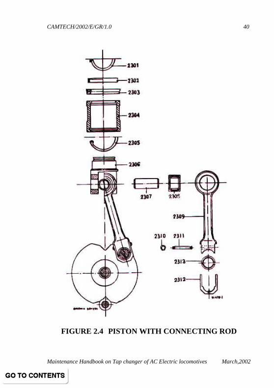
• Remove and dismantle pistons and connecting rods as shown in figure 2.4
Details of figure 2.4
Item Description Item Description
23 Piston with connecting rod
2307 Bearing pin
2301 Circlip 2308 Needle bearing
2302 Thrust ring 2309 Connecting rod
2303 U-section ring 2310 Circlip
2304 Piston skirt 2311 Securing bolts
2305 Circlip 2312 Bearing clamp
2306 Piston 2313 Bearing shells
CAMTECH/2002/E/GR/1.0
Maintenance Handbook on Tap changer of AC Electric locomotives March,2002
40
FIGURE 2.4 PISTON WITH CONNECTING ROD

CAMTECH/2002/E/GR/1.0
Maintenance Handbook on Tap changer of AC Electric locomotives March,2002
41
• Clean cylinder and connecting rod with piston and relubricate.
• Renew worn U-section rings. The shell bearings of the connecting rods must not be cleaned with petrol (gasoline).
• Renew worn bearing shells also being soaked in oil before fitting.
• The crankshaft is removed together with the flywheel and the bearing plates. Swing out notching springs at the notching lever, and then remove nut. Ensure that the crankshaft is not distorted in the process. Use screw clamp to pull off the flywheel.
• Replace worn valve push rods and sealing nipples. Check valve stroke.

CAMTECH/2002/E/GR/1.0
Maintenance Handbook on Tap changer of AC Electric locomotives March,2002
42
2.3.2.1 Dismantling control cylinder
Remove hollow bolts and airlines. Unscrew nuts at screwed pin. Dismantle components as shown in fig. 2.5. On no account unscrew nuts 4413 and 4415, otherwise the piston stoke has to be reset after reassembly. Clean cylinder and piston with clean rag. If necessary renew sealing ring. Before reassembly lightly grease cylinder and piston with approved grease.
FIGURE 2.5 CONTROL CYLINDER ASSEMBLY
4418 4417 4416 4109 4408 4406 4404 4403 4405 4402 4401 4414 4413 4415
4407 4410
4419 4420
4422 4421
4412 4411

CAMTECH/2002/E/GR/1.0
Maintenance Handbook on Tap changer of AC Electric locomotives March,2002
43
Details of figure 2.5
Item Description Item Description
4401 Cylinder 4412 Cylinder cover
4402 Sealing ring 4413 Hexagonal nut
4403 Piston 4414 Seal
4404 Sealing ring 4415 Cap
4405 Buffer 4416 Threaded pin
4406 Setting screw 4417 Spring washer
4407 pin 4418 Hexagonal nut
4408 Centering screw 4419 Gasket
4409 pressure ring 4420 Cover
4410 Spring 4421 Allen screw
4411 Cylinder cover with thread
4422 Spring washer

CAMTECH/2002/E/GR/1.0
Maintenance Handbook on Tap changer of AC Electric locomotives March,2002
44
2.3.2.2 Removal of control lever
Withdraw control unit. Remove circlip and stop washer. Withdraw lever. When refitting lever, ensure that the two red dots •••• •••• on the toothed segment coincide with one of the red dots •••• on pinion. Check clearance of 0.4 to 0.7 mm between guide pin bearing and intermediate wheel with cam plate.
FIGURE 2.6 CONTROL LEVER ASSEMBLY
CAMTECH/2002/E/GR/1.0
Maintenance Handbook on Tap changer of AC Electric locomotives March,2002
45
Details of figure 2.6
Item Description Item Description
4501 Control lever 4521 Guide pin (1)
4502 Toothed segment 4522 Spring loaded pin bearing
4503 Nut locked with pin 4523 Spring loaded pin
4504 Lever link 4524 Pressure spring (1)
4505 Needle bearing support
4525 Guide pin bearing
4506 Needle bearing support roller
4526 Needle bearings (2)
4507 Lever link complete 4527 Cylinder bolt
4508 Hexagonal bolt 4528 Pin
4509 Nut locked with pin 4529 Hexagonal nut
4510 Pin 4530 Pin
4511 Bearing sleeve 4531 Fitting tool for 4512
4512 Needle bearing 4532 Fitting tool for 4526
Check toothed segment and guide pin for wear and renew as necessary. Refit with the help of tools. The components of the control lever are shown in figure 2.6.
2.3.2.3 Removal of camshaft
• Remove circlip, cam plate, key and cover washer. The shaft extension is then pulled through the ball bearing.
• Dismantle camshaft. Components of camshaft are shown in figure 2.7.

CAMTECH/2002/E/GR/1.0
Maintenance Handbook on Tap changer of AC Electric locomotives March,2002
46
• When reassembling camshaft check position of the cam plates with respect to the key ways.
Details of figure 2.7
Item Description Item Description
5101 Shaft 5107 Nut locked with pin
5102 Slotted nut 5108 Circlip
5103 Spring washer 5109 Bearing
5104 Spring plate 5110 Ball bearing
5105 Cam plate (4) 5111 Distance ring
5106 Distance tube 5112 Key
FIGURE 2.7 CAMSHAFT ASSEMBLY

CAMTECH/2002/E/GR/1.0
Maintenance Handbook on Tap changer of AC Electric locomotives March,2002
47
2.3.3 Checks and setting of the solenoid armature strokes
For the operational motor set to step 0 and proceed as follows:
1. Close pressure line cock.
2. Unlatch push rod for valve of cylinder II and IV.
3. Turn drive with flywheel to step 1 and unlatch push rods I and III.
4. Open air line and carry out checks or settings of the solenoids.
5. Close air line.
6. Latch valve push rods I and III and turn drive to step 2.
7. Latch valve push rods II and IV and return drive step 0.
8. Open airline & operate drive Electro- pneumatically.
It is necessary for the various operations to be carried out in the sequence indicated so that the control lever, which changes position during actuation of the valves, can return to the rest position.
2.3.3.1 Armature Setting
• Unscrew nut and unscrew core a few turns. Loosen nut at setting screw.
• Slide 0.5 mm feeler gauge between push rods. • Screw in setting screw until slight leak of air occurs
at valve. • Screw out setting screw until again valve just seals. • Tighten nut and lock.

CAMTECH/2002/E/GR/1.0
Maintenance Handbook on Tap changer of AC Electric locomotives March,2002
48
2.3.3.2 Core Setting
• Depress push rod in direction of arrow until valve opens and seals.
• Screw core in until valve vents slightly. • Unscrew core until valve just seals and then by
another turn (correspondence to an additional 0.5mm armature stroke).
By following this procedure the minimum
armature stroke and the minimum attraction voltage of the solenoid is obtained. Check valves of correct operation and lock nuts with tab washers.
2.3.4 Changing Cam Plates
• Unscrew the carrier plate with the connections after removing bolts.
• Turn switch drum until slots in cam plates is to the rear.
• Using 36-mm spanner hold nut locked with pin and loosen slotted nut with hooked spanner until sufficient play is obtained.
• Slightly tilt cam plate to be replaced so that it can be withdrawn from the guide groove of the distance sleeve. Pull out cam plates towards the front.

CAMTECH/2002/E/GR/1.0
Maintenance Handbook on Tap changer of AC Electric locomotives March,2002
49
2.4 CHECK SHEET FOR OVERHAULING
S.N ITEM Standard Actual 1. Check complete body,
contact plate and segment etc. for any crack and damage.
No crack No damage
2. Check bevel wheels for any wear tear.
No wear & tear.
3. Check the bearing condition.
Good.
4. Check double pole bushing for any crack and damage.
No crack.
5. Check the insulation resistance with 2.5 kV.Megger between a) Pole to pole b)Pole to earth
100 M. ohm
6. Replace all rubber items & oil seal 100%.
To be Replaced.
7. Check the height of contact arm spring under load test of 6.2 kg. as per SMI-8.
15.3mm (min.)
8. Check the contact roller for any pitting and over heating.
No pitting & overheating
9. Check the contact roller diameter.
17mm (min.)
10. Check radial play between contact roller pin & bearing.
0.4 mm.

CAMTECH/2002/E/GR/1.0
Maintenance Handbook on Tap changer of AC Electric locomotives March,2002
50
S.N ITEM Standard Actual
11. Check play between contact roller housing.
Around 0 to 5 mm.
12. Check the wear on contact track. If found excessive wear or surface is very rough, replace them.
0.5 mm deep (Max.)
13. Check the gap between contact segment and contact plate at back side.
3 to 1mm.
14. Check the diameter of lantern gear pinion rollers.
15.5 mm(Min.)
15. Check the contact roller position on contact ring.
Middle ± 3mm
16. Check movement play at contact arm - a) Breaker on tapping Position, pin of lantern
gear pinion vertical Move contact arm to
and fro by hand. The total deflection should not exceed the standard value.
b) Breaker in intermediate position, pin of lantern gear Horizontal.
The total deflection of contact arm should not exceed the standard value.
10 mm (Max.) 4 mm (Max.)

CAMTECH/2002/E/GR/1.0
Maintenance Handbook on Tap changer of AC Electric locomotives March,2002
51
S.N ITEM Standard Actual
17. Check the tightness of the following with torque wrenches.
a) Hexagonal bolt on selector housing with moving frame.
b) Special hexagonal bolt for fixing insulating ring inner and outer.
c) Special nut and conical nut-part. No. 1214 & 1217.
3.5 M-kg.
0.5 to 0.6 M-kg.
2.0 to 2.5 M-kg.
18. Check the dielectric strength of oil for 1 minute with 2.5 mm gap between 13 mm diameter spheres.
50 kV
19. Check free operation of safety valve
Free
20. Clean the oil indicator & check oil level.
Above 20° C mark
21. Making & braking angles of GR
Inner ring.
Outer ring

CAMTECH/2002/E/GR/1.0
Maintenance Handbook on Tap changer of AC Electric locomotives March,2002
52
S.N ITEM Standard Actual
22. Check the degree setting of CGR make and brake
CGR-I CGR-II Close Open Close CGR-III
35± 3 - 145± 3
125± 3 - 145± 3
170± 3 - 190± 3
23. Check the condition of potential contact
Good
24. Replace PHGR filter 100% Replaced
25. Replace all rubber 'O' ring of PHGR 100%.
Replaced
26. Check the working of PHGR at 3 Kg/Cm2 pressure
30 to 40 strokes per minute.
27. Check for any oil leakage. No leakage
28. Check the three way cock hole dia. as per SMI-88.
8.5 mm
29. Check the colour of silicagel
Blue
30. Any other remarks.

CAMTECH/2002/E/GR/1.0
Maintenance Handbook on Tap changer of AC Electric locomotives March,2002
53
CHAPTER 3
STICKING OF SMGR,CAUSES AND SUGGESTIONS TO AVOID FAILURES
OF GR/ SMGR
3.1 STICKING OF SMGR
Probable causes for sticking of SMGR may be following.
1. Guide pin (part No. 4521) stuck up.
2. Gap between control lever and intermediate gear exceeds 0.7mm.
3. Pressure leakage from MG 6/6A and MG 4/5 A valves.
4. Improper setting of control block.
5. Progression and regression time of SMGR become more/ less ( 9 to 13 seconds)
6. Lifting valve plunger (part no. 5317) stuck up.
7. Improper profile of intermediate gear segment/ breakage or crack of segment.

CAMTECH/2002/E/GR/1.0
Maintenance Handbook on Tap changer of AC Electric locomotives March,2002
54
3.1.1 Reasons for guide pin jam
a. Deposition of dry grease around guide pin.
b. Deposition of grease in the intermediate gear segment.
c. Loss of spring tension or breakage of compression spring of control lever guide pin.
d. Rubbing of wearing plate of control lever with guide pin.
3.1.2 Gap between control lever and intermediate gear exceeds 0.7mm
a. Increasing or decreasing play between control lever and circlip provided on journal pin due to less or more shim washer (part no. 4515)
b. Loosening of needle bearing of control lever provided on journal pin.
c. Journal pin worn out.
d. Internal play between intermediate gear and bearing pin.
e. Less or more shim washer between intermediate gear and circlip.
f. Bending of control lever (part no. 4501)
g. Pin (part no. 6109) worn out.
h. Needle bearing (part no. 6104) worn out at journal pin end.
i. Improper fitting of journal pin.

CAMTECH/2002/E/GR/1.0
Maintenance Handbook on Tap changer of AC Electric locomotives March,2002
55
3.1.3 Pressure leakage from MG 6/6A and MG 4/5A valves
a. Improper setting of valve plunger.
b. Valve plunger part no. 3209/429 stuck up.
c. Valve jam due to corrosion.
d. Improper sitting of push rod and lifting valve plunger.
e. Mis-alignment of push rod.
f. Valve seat defective.
3.1.4 Improper setting of control block
a. Improper setting of control cylinder affected lead angle.
b. Not using proper grease (Bharat MP-2) between control cylinder and piston as well as increased greasing interval.
c. Using inferior quality of 'U' section ring (bucket)
d. Leakage of air from air coupling in the SMGR.
e. Pressure settings become less or more through pressure reducing valve on control panel.

CAMTECH/2002/E/GR/1.0
Maintenance Handbook on Tap changer of AC Electric locomotives March,2002
56
3.2 SUGGESTIONS TO AVOID FAILURES OF GR/ SMGR
1. Guide pin should be lubricated only by machine oil H 20/1.
2. Segments of intermediate gear should be lubricated only by graphite oil.
3. Repositioning of wearing plate should be done when it is rubbing with control lever of guide pin. Compression spring must be changed during POH.
4. Gap between control lever and intermediate gear segment should be maintained between 0.4 to 0.7 mm. This gap should be checked during every IA/IB/IC/ schedules.
5. Air leakage test of SMGR should be performed in every schedule. The leakage should not be more than 10% in 10 minutes.
6. Free movement of valve plunger should be ensured in every AOH. The valve plunger should be replaced in every POH.
7. Gap between adjustable valve screw and bolt head should be maintained between 0.4 to 0.7mm. This gap should be checked during every IA/IB/IC schedule.
8. Plunger should move free in the bearing pin with strap part no. 5301. The play between spacer and shim should not be more than 0.2mm.
9. The setting of control block should be ensured.
CAMTECH/2002/E/GR/1.0
Maintenance Handbook on Tap changer of AC Electric locomotives March,2002
57
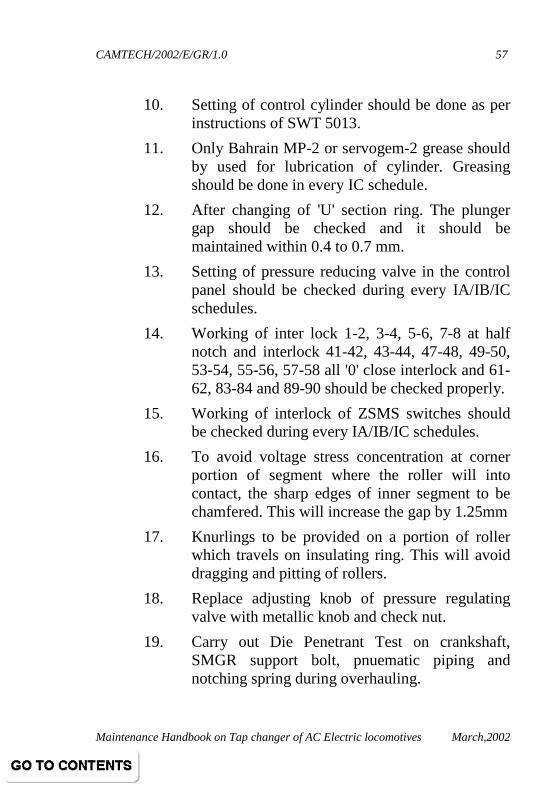
10. Setting of control cylinder should be done as per instructions of SWT 5013.
11. Only Bahrain MP-2 or servogem-2 grease should by used for lubrication of cylinder. Greasing should be done in every IC schedule.
12. After changing of 'U' section ring. The plunger gap should be checked and it should be maintained within 0.4 to 0.7 mm.
13. Setting of pressure reducing valve in the control panel should be checked during every IA/IB/IC schedules.
14. Working of inter lock 1-2, 3-4, 5-6, 7-8 at half notch and interlock 41-42, 43-44, 47-48, 49-50, 53-54, 55-56, 57-58 all '0' close interlock and 61-62, 83-84 and 89-90 should be checked properly.
15. Working of interlock of ZSMS switches should be checked during every IA/IB/IC schedules.
16. To avoid voltage stress concentration at corner portion of segment where the roller will into contact, the sharp edges of inner segment to be chamfered. This will increase the gap by 1.25mm
17. Knurlings to be provided on a portion of roller which travels on insulating ring. This will avoid dragging and pitting of rollers.
18. Replace adjusting knob of pressure regulating valve with metallic knob and check nut.
19. Carry out Die Penetrant Test on crankshaft, SMGR support bolt, pnuematic piping and notching spring during overhauling.

CAMTECH/2002/E/GR/1.0
Maintenance Handbook on Tap changer of AC Electric locomotives March,2002
58
20. Ensure implementation of various SMI's/ MI's issued by RDSO as per annexure - A.
21. Ensure 100% replacement of " Must change items" during AOH, IOH and POH.
22. Perform leakage testing of SMGR after overhauling.
23. Conduct load testing of SMGR along with GR and CGR on test panel.
24. Paralleling of SMGR cam switch.
25. Align SMGR crankshaft during overhauling as per adtranz jigs and fixture.
26. Take measures to prevent burning of notch repeater.
27. Perform dielectric test of GR oil in every IC. Conduct BDV testing with 100 kV motorised equipment.
28. Flushing of oil if BDV found less.
29. Flushing of new tap changer oil after 10,000km or where more than 25% taps have been changed.
30. Provide modified PHGR and test on test bench during AOH/IOH schedules.
31. Ensure replacement of rubber kit during every AOH/IOH & POH.
32. Use set of special tools of M/s Adtranz.
33. Ensure quality control of CGR contacts, GR segments, roller, contact ring, insulating ring and contact plate.

CAMTECH/2002/E/GR/1.0
Maintenance Handbook on Tap changer of AC Electric locomotives March,2002
59
34. Ensure periodic replacement of insulating oil and silica gel of air dryer of GR.
35. Use direct filling arrangement for GR.
36. Use of high temperature grease type MECK BR-300 for CGR.
37. Measure switching angle of contact segment of GR in AOH, IOH and POH.
38. Check pneumatic pipe line from EV PHGR to PHGR for crackness, air leakage from drain cocks etc. during periodic schedules.
39. Conduct DGA of tap changer oil in IC.
40. Plan to replace cast grid RGR with steel punched grid RGR.
41. Procure set of two sealing rings for control cylinder of SMGR in kit from approved sources only.
42. Ensure replacement of worn out shaft on condition basis both top and bottom oil seal during AOH & IOH.
43. Clean hollow insulator, bake at 80°C then apply anti tracking varnish.
44. Ensure modification of 16th tap connection by flexible connection.
45. Check operation of safety valve after fitment of canopy.

CAMTECH/2002/E/GR/1.0
Maintenance Handbook on Tap changer of AC Electric locomotives March,2002
60
ANNEXURE - A
LIST OF SMI'S/MI'S
S.No. Title No.
1. Breakage of MOM taper pin. RDSO/ELRS/SMI/17
2. Malfunctioning of modified control lever of TC
RDSO/ELRS/SMI/18
3. Sluggish operation of SMGR RDSO/ELRS/SMI/20
4. Breakage of support block of auxiliary switch.
RDSO/ELRS/SMI/21
5. Sticking up of tap changer between notches
RDSO/ELRS/SMI/22
6. Sticking of control lever guide pin.
RDSO/ELRS/SMI/46
7. Adjustment of lead angle of control cylinder.
RDSO/ELRS/SMI/48
8. Lubrication to be used for TC. RDSO/ELRS/SMI/49
9. Testing of contact pressure of CGR 1,2,3
RDSO/ELRS/SMI/50
10. Lubricants to be used for GR RDSO/ELRS/SMI/80
11. Roller contact force in GR RDSO/ELRS/SMI/82
12. Oil leakage through three way cock
RDSO/ELRS/SMI/88
CAMTECH/2002/E/GR/1.0
Maintenance Handbook on Tap changer of AC Electric locomotives March,2002
61
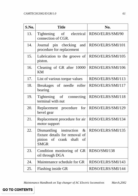
S.No. Title No.
13. Tightening of electrical connection of CGR.
RDSO/ELRS/SMI/90
14. Journal pin checking and procedure for replacement
RDSO/ELRS/SMI/101
15. Lubrication to the groove of piston.
RDSO/ELRS/SMI/105
16. Cleaning of GR after 10000 KM
RDSO/ELRS/SMI/106
17. List of various torque values RDSO/ELRS/SMI/113
18. Breakages of needle roller bearing
RDSO/ELRS/SMI/117
19. Tightening of connecting terminal with nut
RDSO/ELRS/SMI/118
20. Replacement procedure for bevel gear
RDSO/ELRS/SMI/129
21. Replacement procedure for air motor support
RDSO/ELRS/SMI/134
22. Dismantling instruction & fixture details for removal of pinion of crank shaft of SMGR
RDSO/ELRS/SMI/135
23. Condition monitoring of GR oil through DGA
RDSO/SMI/138
24. Maintenance schedule for GR RDSO/ELRS/SMI/143
25. Flashing inside GR RDSO/ELRS/SMI/144

CAMTECH/2002/E/GR/1.0
Maintenance Handbook on Tap changer of AC Electric locomotives March,2002
62
S.No. Title No.
26. Crank shaft fracture RDSO/ELRS/SMI/145
27. Breakage of pin of SMGR RDSO/ELRS/SMI/146
28. Support for oil indicator to Tap changer
RDSO/WAM4/62.
29. Provision of taper hole to accommodate the taper pin in the manual drive of Tap changer
RDSO/WAM4/69.
30. Clamping arrangement for PHGR
RDSO/WAM4/114
31. Modification to fixing arrangement for blow out coil of CGR to ensure locking of Tap changer
RDSO/WAM4/128.
32. Modified flexible connection between RGR & GR of Tap changer
RDSO/WAM4/136.
33. Introduction of locktite between the mating surface of cams & cam shaft, grub screw and taper holes of Tap Changer
RDSO/WAM4/145.
34. Provision of grub screw locking for CG bush & gear housing assembly of manual drive for tap changer
RDSO/WAM4/146.
CAMTECH/2002/E/GR/1.0
Maintenance Handbook on Tap changer of AC Electric locomotives March,2002
63
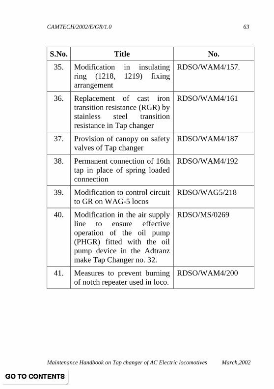
S.No. Title No.
35. Modification in insulating ring (1218, 1219) fixing arrangement
RDSO/WAM4/157.
36. Replacement of cast iron transition resistance (RGR) by stainless steel transition resistance in Tap changer
RDSO/WAM4/161
37. Provision of canopy on safety valves of Tap changer
RDSO/WAM4/187
38. Permanent connection of 16th tap in place of spring loaded connection
RDSO/WAM4/192
39. Modification to control circuit to GR on WAG-5 locos
RDSO/WAG5/218
40. Modification in the air supply line to ensure effective operation of the oil pump (PHGR) fitted with the oil pump device in the Adtranz make Tap Changer no. 32.
RDSO/MS/0269
41. Measures to prevent burning of notch repeater used in loco.
RDSO/WAM4/200
CAMTECH/2002/E/GR/1.0
Maintenance Handbook on Tap changer of AC Electric locomotives March,2002
64
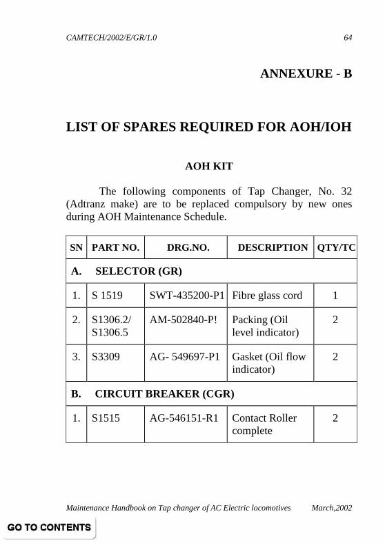
ANNEXURE - B
LIST OF SPARES REQUIRED FOR AOH/IOH
AOH KIT
The following components of Tap Changer, No. 32 (Adtranz make) are to be replaced compulsory by new ones during AOH Maintenance Schedule.
SN PART NO. DRG.NO. DESCRIPTION QTY/TC
A. SELECTOR (GR)
1. S 1519 SWT-435200-P1 Fibre glass cord 1
2. S1306.2/ S1306.5
AM-502840-P! Packing (Oil level indicator)
2
3. S3309 AG- 549697-P1 Gasket (Oil flow indicator)
2
B. CIRCUIT BREAKER (CGR)
1. S1515 AG-546151-R1 Contact Roller complete
2

CAMTECH/2002/E/GR/1.0
Maintenance Handbook on Tap changer of AC Electric locomotives March,2002
65
SN PART NO. DRG.NO. DESCRIPTION QTY/TC
C. OIL FILTRATION UNIT
1. S3235 SWT-435167-P1 Cup Seal 2
2. S3270.3 SWT-435167-P2 Cup Seal 2
3. S3221/ S3225
SWT-435430-P3 'O' Ring 1
4. S3224/ S3252
SWT-435430-P2 'O' Ring 2
5. S3251 SWT-435430-P5 'O' Ring 6
6. S3254 SWT-235033-P27 Gasket 1
7. 0450222008/ HB Mico Filter Element 1
D. AIR MOTOR
1. A1213 SWT-435144-P2 Packing Ring 4
2. A2303 SWT-435461-P1 Sealing Ring 4
3. A3108 AG- 544441-P2 Gasket 4
4. A3111/ A4120/ A4430.19
AG- 544441-P1 Gasket 8
5. A4430.4 AM-404742-P1 Packing Ring 2
6. A4430.2 AG-413762-P25 Damping Gasket 2 Note: The above list does not include standard hardware items
(such as Roll pins, circlips, washers, copper washers etc.) which also need to be changed during AOH.

CAMTECH/2002/E/GR/1.0
Maintenance Handbook on Tap changer of AC Electric locomotives March,2002
66
IOH KIT The following components of Tap Changer, No.32
(Adtranz make) are to be replaced compulsory by new ones during IOH Maintenance Schedule A. SELECTOR (GR)
SN PART NO. DRG.NO. DESCRIPTION QTY/TC
1. S1519 SWT-435200-P1 Fibre Glass Cord
1
2. S1306.2/A1306.5
AM-502840-P1 packing (oil level indicator)
2
3. S3309 AG-549697-P1 Gasket (oil flow indicator)
2
4. S1303 AG-207812-P1 Gasket 1
5. S1320.1 AG-544325-P4 Packing Ring 2
6. S1434/ S1440
SWT-435381-P1 Oil seal 2
7. S1421 AG-544325-P5 Packing ring 1
8. S1218 AM-200095-R2 Insulating ring (inner)
1
9. S1219 AM-200095-R1 Insulating ring (outer)
1
10. S1515 AG-546151-R1 Contact roller complete
2

CAMTECH/2002/E/GR/1.0
Maintenance Handbook on Tap changer of AC Electric locomotives March,2002
67
B. CIRCUIT BREAKER (CGR)
SN PART NO. DRG.NO. DESCRIPTION QTY/TC
1. S2529 AG-540123-P1 Contact 6 C. OIL FILTRATION UNIT (PHGR Circuit)
SN PART NO. DRG.NO. DESCRIPTION QTY/TC
1. S3235 SWT-435167-P1 Cup seal 2
2. S3270.3 SWT-435167-P2 Cup seal 2
3. S3221/ S3225
SWT-435430-P3 'O' ring 1
4. S3224/ S3252
SWT-435430-P2 'O' ring 2
5. S3251 SWT-435430-P5 'O' ring 6 6. S3254 SWT-235033-P27 Gasket 1
7. 0450222008/HB Mico filter element
1
D. CU GASKETS
For oil pipe line, oil flow indicator, oil pump device.
SN PART NO. DRG.NO. DESCRIPTION QTY/TC
1. S3290.12 MT-430152-P19 CU Gasket 2 2. S3290.14 MT-430152-P18 CU Gasket 2 3. S3290.10 MT-430152-P13 CU Gasket 1 4. S3290.17 SWT-435491-P13 CU Gasket 1 5. S3433 MT-430152-P34 Gasket 7
6. S3422/ S3406
MT-430152-P23 Gasket 20
CAMTECH/2002/E/GR/1.0
Maintenance Handbook on Tap changer of AC Electric locomotives March,2002
68
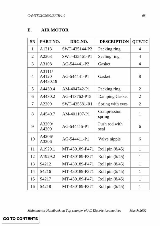
E. AIR MOTOR
SN PART NO. DRG.NO. DESCRIPTION QTY/TC
1 A1213 SWT-435144-P2 Packing ring 4
2 A2303 SWT-435461-P1 Sealing ring 4
3 A3108 AG-544441-P2 Gasket 4
4 A3111/ A4120 A4430.19
AG-544441-P1 Gasket 8
5 A4430.4 AM-404742-P1 Packing ring 2
6 A4430.2 AG-413762-P15 Damping Gasket 2
7 A2209 SWT-435581-R1 Spring with eyes 2
8 A4540.7 AM-401107-P1 Compression spring
1
9 A3209/ A4209
AG-544415-P1 Push rod with seal
6
10 A4206/ A3206
AG-544411-P1 Valve nipple 6
11 A1929.1 MT-430189-P471 Roll pin (8/45) 1
12 A1929.2 MT-430189-P371 Roll pin (5/45) 1
13 S4212 MT-430189-P471 Roll pin (8/45) 1
14 S4216 MT-430189-P371 Roll pin (5/45) 1
15 S4217 MT-430189-P471 Roll pin (8/45) 1
16 S4218 MT-430189-P371 Roll pin (5/45) 1
CAMTECH/2002/E/GR/1.0
Maintenance Handbook on Tap changer of AC Electric locomotives March,2002
69
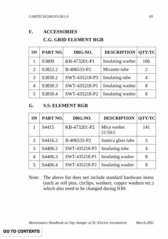
F. ACCESSORIES
C.G. GRID ELEMENT RGR
SN PART NO. DRG.NO. DESCRIPTION QTY/TC
1 S3809 KB-473201-P1 Insulating washer 106
2 S3822.2 B-406533-P2 Micanite tube 2
3 S3830.2 SWT-435218-P3 Insulating tube 4
4 S3830.3 SWT-435218-P1 Insulating washer 8
5 S3830.4 SWT-435218-P2 Insulating washer 8 G. S.S. ELEMENT RGR
SN PART NO. DRG.NO. DESCRIPTION QTY/TC
1 S4415 KB-473201-P2 Mica washer 21/50/2
141
2 S4416.2 B-406533-P2 Samica glass tube 3
3 S4406.2 SWT-435218-P3 Insulating tube 4
4 S4406.3 SWT-435218-P1 Insulating washer 8
5 S4406.4 SWT-435218-P2 Insulating washer 8
Note: The above list does not include standard hardware items
(such as roll pins, circlips, washers, copper washers etc.) which also need to be changed during IOH.

CAMTECH/2002/E/GR/1.0
Maintenance Handbook on Tap changer of AC Electric locomotives March,2002
70
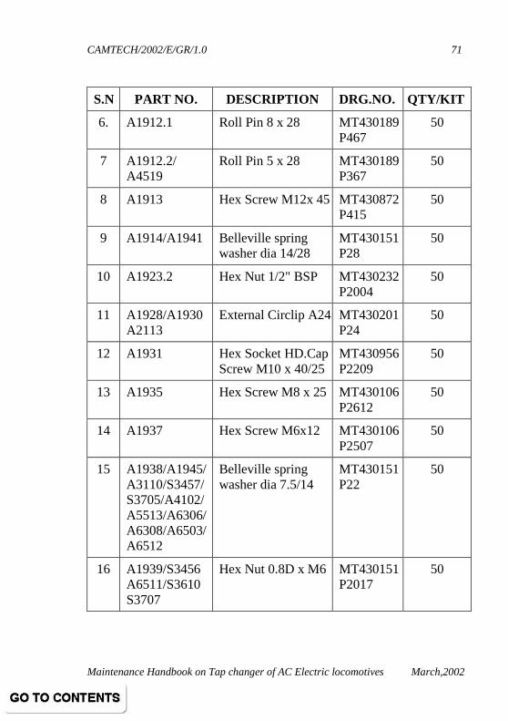
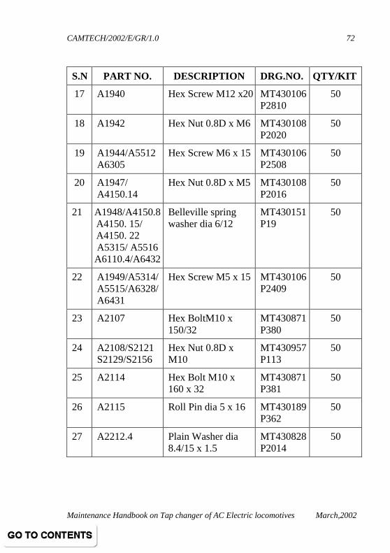
ANNEXURE - C
KIT OF STANDARD HARDWARE FOR TAP CHANGER
S.N PART NO. DESCRIPTION DRG.NO. QTY/KIT
1 A1906 Hex Screw M8 x 20 MT430106 P2610
50
2. A1907/A1936 A6302/A6418 A6509/A6514 S1415/S1460 S1464/S1611 S1614/S2127 S2182/S3450
S3816/S3905
Belleville spring washer dia 9/18
MT430151 P23
50
3. A1908/S2183
S3449/A6508
Hex Nut 0.8D x M8 MT430108 P 2018
50
4. A1909 Hex Screw M10 x30 MT430872 P362
50
5. A1910/A2109 A4127/S1109 S1112/S1204 S1305/S1403 S1603/S2117 S2120/S2134 S2149/S2155 S3426/S3453
S3710
Belleville spring washer dia 11/22
MT430151 P26
50
CAMTECH/2002/E/GR/1.0
Maintenance Handbook on Tap changer of AC Electric locomotives March,2002
71
S.N PART NO. DESCRIPTION DRG.NO. QTY/KIT
6. A1912.1 Roll Pin 8 x 28 MT430189 P467
50
7 A1912.2/ A4519
Roll Pin 5 x 28 MT430189 P367
50
8 A1913 Hex Screw M12x 45 MT430872 P415
50
9 A1914/A1941 Belleville spring washer dia 14/28
MT430151 P28
50
10 A1923.2 Hex Nut 1/2" BSP MT430232 P2004
50
11 A1928/A1930 A2113
External Circlip A24 MT430201 P24
50
12 A1931 Hex Socket HD.Cap Screw M10 x 40/25
MT430956 P2209
50
13 A1935 Hex Screw M8 x 25 MT430106 P2612
50
14 A1937 Hex Screw M6x12 MT430106 P2507
50
15 A1938/A1945/ A3110/S3457/ S3705/A4102/ A5513/A6306/ A6308/A6503/ A6512
Belleville spring washer dia 7.5/14
MT430151 P22
50
16 A1939/S3456 A6511/S3610 S3707
Hex Nut 0.8D x M6 MT430151 P2017
50
CAMTECH/2002/E/GR/1.0
Maintenance Handbook on Tap changer of AC Electric locomotives March,2002
72
S.N PART NO. DESCRIPTION DRG.NO. QTY/KIT
17 A1940 Hex Screw M12 x20 MT430106 P2810
50
18 A1942 Hex Nut 0.8D x M6 MT430108 P2020
50
19 A1944/A5512 A6305
Hex Screw M6 x 15 MT430106 P2508
50
20 A1947/ A4150.14
Hex Nut 0.8D x M5 MT430108 P2016
50
21 A1948/A4150.8 A4150. 15/ A4150. 22 A5315/ A5516 A6110.4/A6432
Belleville spring washer dia 6/12
MT430151 P19
50
22 A1949/A5314/ A5515/A6328/ A6431
Hex Screw M5 x 15 MT430106 P2409
50
23 A2107 Hex BoltM10 x 150/32
MT430871 P380
50
24 A2108/S2121 S2129/S2156
Hex Nut 0.8D x M10
MT430957 P113
50
25 A2114 Hex Bolt M10 x 160 x 32
MT430871 P381
50
26 A2115 Roll Pin dia 5 x 16 MT430189 P362
50
27 A2212.4 Plain Washer dia 8.4/15 x 1.5
MT430828 P2014
50

CAMTECH/2002/E/GR/1.0
Maintenance Handbook on Tap changer of AC Electric locomotives March,2002
73
S.N PART NO. DESCRIPTION DRG.NO. QTY/KIT
28 A2301 External Circlip 152
MT430201 P42
50
29 A2314.2/S1405.1S1433/S1441 S1503/S2111
Internal Circlip 152
MT430202 P52
50
30 A3109 Hex Bolt M6 x 70/ 18
MT439005 P270
50
31 A3207/A2407 Internal Circlip 116
MT430202 P16
50
32 A4101 Hex Bolt M6 x 45/ 17
MT430222 P2514
50
33 A4124 Hex Socket HD. Screw M8 x 70/22
MT430511 P215
50
34 A4125/S4517 Belleville spring washer M8 x70/22
MT430190 P118
50
35 A4134/A6502 Hex Bolt M6 x 30/ 17
MT430222 P2511
50
36 A4139 Slotted head screw M8 x 25
MT430229 P2930
50
37 A4150.11/ A4150.16
Counter sunk Screw 90° M5 x10
MT430237 P2713
50
38 A4150.21 A6110.3
Hex Screw M5 x10 MT430106 P2406
50
39 A4150.32 Hex Nut 0.5D xM6 MT430439 P2012
50
40 A4150.7 Hex Screw M5 x12 MT430106 P2407
50
CAMTECH/2002/E/GR/1.0
Maintenance Handbook on Tap changer of AC Electric locomotives March,2002
74
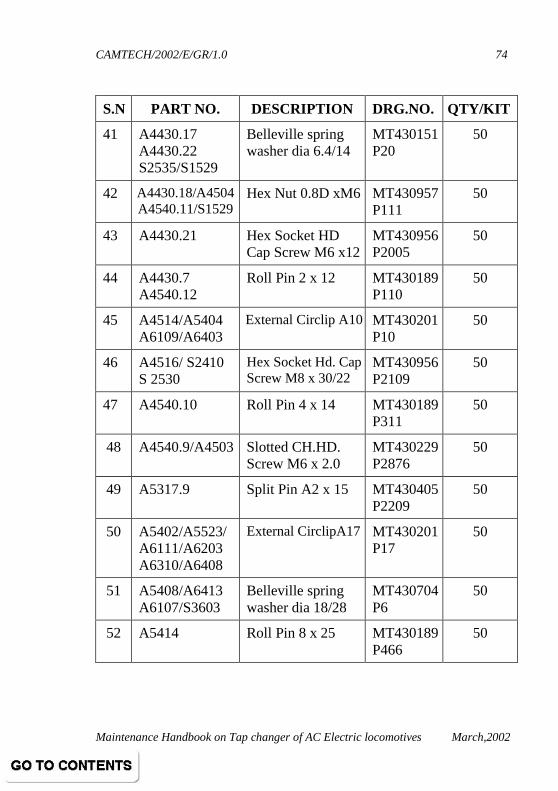
S.N PART NO. DESCRIPTION DRG.NO. QTY/KIT
41 A4430.17 A4430.22 S2535/S1529
Belleville spring washer dia 6.4/14
MT430151 P20
50
42 A4430.18/A4504 A4540.11/S1529
Hex Nut 0.8D xM6 MT430957 P111
50
43 A4430.21 Hex Socket HD Cap Screw M6 x12
MT430956 P2005
50
44 A4430.7 A4540.12
Roll Pin 2 x 12 MT430189 P110
50
45 A4514/A5404 A6109/A6403
External Circlip A10 MT430201 P10
50
46 A4516/ S2410 S 2530
Hex Socket Hd. Cap Screw M8 x 30/22
MT430956 P2109
50
47 A4540.10 Roll Pin 4 x 14 MT430189 P311
50
48 A4540.9/A4503 Slotted CH.HD. Screw M6 x 2.0
MT430229 P2876
50
49 A5317.9 Split Pin A2 x 15 MT430405 P2209
50
50 A5402/A5523/ A6111/A6203 A6310/A6408
External CirclipA17 MT430201 P17
50
51 A5408/A6413 A6107/S3603
Belleville spring washer dia 18/28
MT430704 P6
50
52 A5414 Roll Pin 8 x 25 MT430189 P466
50

CAMTECH/2002/E/GR/1.0
Maintenance Handbook on Tap changer of AC Electric locomotives March,2002
75
S.N PART NO. DESCRIPTION DRG.NO. QTY/KIT
53 A5509/A6327 A6426
Belleville spring washer dia 32/48
MT430704 P10
50
54 A5517 Hex Bolt M8 x 80/ 22
SWT439005 P322
50
55 A5521/A6317 A6405
Roll Pin 4 x 36 MT430189 P319
50
56 A5524/A6417 A6209/A6309
Internal Circlip 140 MT430202 P40
50
57 A6114 Hex Bolt M8 x 45/21
MT430222 P 2614
50
58 A6115 Special washer dia 8.4 x 15
MT430198 P17
50
59 A6205 Slotted Ch HD Screw M4 x 20
MT430229 P2676
50
60 A6301 Hex Screw M 6 x 25
MT430872 P2211
50
61 A6307 Hex Bolt M6 x 130/18
SWT439005 P278
50
62 A6311 Roll Pin dia 6 x 28 MT430189 P417
50
63 A6420/S1416 S1528/S2514 S2525/S3906
Hex Nut 0.8 D x M8
MT430957 P112
50
64 A6506/S2160.6 Hex Bolt M6 x 35/70
MT430222 P2512
50
65 S1101.2 Helicoil M 10 x 1.5 P x 1.5D
MT430935 P62
50

CAMTECH/2002/E/GR/1.0
Maintenance Handbook on Tap changer of AC Electric locomotives March,2002
76
S.N PART NO. DESCRIPTION DRG.NO. QTY/KIT
66 S1105 Gasket Diameter 21/ 25 x 1
MT430152 P28
50
67 S1108/S1304 Hex Screw M10 x 30
MT430872 P 2362
50
68 S1111/S1404 S1427/S1602 S2133/S2148 S3714
Hex Screw M10 x 25
MT430872 P2361
50
69 S1203 Hex Bolt M10 x 55/ 26
MT430871 P367
50
70 S1220/S2160.2 Belleville spring washer dia 6.4/14
MT430190 P116
50
71 S1227/S1436 Roll Pin dia 3 x 25 MT430189 P216
50
72 S1230 Roll Pin 3 x 12 MT430189 P210
50
73 S1411/S1615 S2205/S2220.5
External Circlip A25
MT430201 P25
50
74 S1414/S1461 Hex Bolt M8 x 40/22
SWT439005 P 314
50
75 S1422 CH HD Screw M5 x 10
MT430229 P2766
50
76 S1447 External Circlip A20
MT430201 P20
50
77 S1451 Hex Bolt M8 x 25 MT430872 P2261
50

CAMTECH/2002/E/GR/1.0
Maintenance Handbook on Tap changer of AC Electric locomotives March,2002
77
S.N PART NO. DESCRIPTION DRG.NO. QTY/KIT
78 S1465 External Circlip A55
MT430201 P 55
50
79 S1469 Internal Circlip 142 MT430202 P 42
50
80 S1471 Slotted head Grub Screw M5 x 6
MT430440 P2706
50
81 S1480.1/S1481.1 S1929.1/S2104/ S2100.2/S2210.1
Roll Pin 8 x 45 MT430189 P 147
50
82 S1480.2/A1481.2 /A1929.2
S2104.2/ S2210.2
Roll Pin 5 x 46 MT430189 P371
50
83 S1507 Hex Bolt M8 x 75/22
SWT439005 P 271
50
84 S1510 Hex Bolt M6 x 80/18
SWT439005 P 272
50
85 S1530/S3706 S3909
Punched washer diameter 6.6/12
MT430827 P2011
50
86 S1610/S3903 Hex Screw M8 x16 MT430872 P2259
50
87 S2216/S3709 Hex Bolt M10 x 35/26
MT430871 P363
50
88 S2119/S2154 Hex Bolt M10 x 45/25
MT430871 P365
50
89 S2126 Hex lock Nut 0.5D x M8
MT430439 P2013
50

CAMTECH/2002/E/GR/1.0
Maintenance Handbook on Tap changer of AC Electric locomotives March,2002
78
S.N PART NO. DESCRIPTION DRG.NO. QTY/KIT
90 S2128 Hex Bolt M10 x 120/25
MT430871 P 377
50
91 S2145/S2161 S3406
CU Gasket diameter 14/20 x 1
MT430152 P23
50
92 S2153 Belleville spring washer dia 13.5/28
MT430190 P122
50
93 S2164 Roll Pin dia 5 x 20 MT430189 P364
50
94 S2184 Punched washer diameter 9/17
MT430827 P2015
50
95 S2185/S3448 Hex Screw M8 x 30 MT430106 P2614
50
96 S2404 Hex Bolt M6 x 30 MT430872 P2210
50
97 S2406 Hex Socket head cap screw M6 x 30
MT430956 P2009
50
98 S2407 CU Gasket diameter 6.5/11.2 x 1
MT430152 P11
50
99 S2408/S2532 Hex Socket head screw M6 x 20
MT430956 P2007
50
100 S2409 Punched washer dia 6.6/11 x 1.6
MT430828 P2011
50
101 S2411 Spring washer SWT 435227 P1
50
102 S2413 Hex Socket head screw M12 x 35
MT430956 P108
50
CAMTECH/2002/E/GR/1.0
Maintenance Handbook on Tap changer of AC Electric locomotives March,2002
79
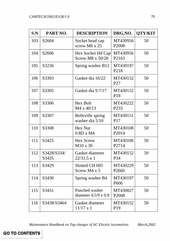
S.N PART NO. DESCRIPTION DRG.NO. QTY/KIT
103 S2604 Socket head cap screw M6 x 25
MT430956 P2008
50
104 S2606 Hex Socket Hd Cap Screw M8 x 50/28
MT430956 P2163
50
105 S3236 Spring washer B12 MT430197 P218
50
106 S3303 Gasket dia 16/22 MT430152 P27
50
107 S3305 Gasket dia 9.7/17 MT430152 P18
50
108 S3306 Hex Bolt M4 x 40/13
MT430222 P233
50
109 S3307 Belleville spring washer dia 5/10
MT430151 P17
50
110 S3308 Hex Nut 0.8D x M4
MT430108 P2014
50
111 S3425 Hex Screw M10 x 30
MT430106 P2714
50
112 S3428/S334/ S3435
Gasket diameter 22/31.5 x 1
MT430152 P34
50
113 S3429 Slotted CH HD Screw M4 x 5
MT430229 P2660
50
114 S3430 Spring washer B4 MT430197 P606
50
115 S3431 Punched washer diameter 4.5/9 x 0.8
MT430827 P2008
50
116 S3438/S3464 Gasket diameter 11/17 x 1
MT430152 P19
50

CAMTECH/2002/E/GR/1.0
Maintenance Handbook on Tap changer of AC Electric locomotives March,2002
80
S.N PART NO. DESCRIPTION DRG.NO. QTY/KIT
117 S3441/S3611 Hex Screw M6 x20 MT430106 P2510
50
118 S3451 Hex Bolt M10 x 35/25
MT430222 P2712
50
119 S3421/S3452 Hex Nut diameter 0.8D x M10
MT430108 P2019
50
120 S3454 Punched washer diameter 10.5/22
MT430827 P2017
50
121 S3455 Hex Screw M6 x25 MT430106 P2512
50
122 S3602 Gasket diameter 17/34 x 3
MT430152 P42
50
123 S3404 Special Nut 3/8"BSP
MT430232 P2003
50
124 S3609 Belleville Spring washer dia 6.4/14
MT430151 P21
50
125 S3704 Hex Screw M6 x35 MT430106 P2515
50
126 S3814 Hex Screw M8 x20 MT430106 P4610
50
127 S3818 Hex Screw M12 x 30
MT430872 P412
50
128 S3904 Plain washer diameter 8.4/18 x0.5
MT430445 P2023
50
129 S3908 Rivet diameter 3 x 8
MT430223 P8563
50

CAMTECH/2002/E/GR/1.0
Maintenance Handbook on Tap changer of AC Electric locomotives March,2002
81
REFERENCES
1. Maintenance manual of CLW for electric locomotives.
2. AC Traction manual.
3. IRIEEN journals.
4. Maintenance Schedules issued from Central Railway Head Quarter, MBCST.
5. Maintenance Schedules of Northern Railway, GZB, Western Railway, TKD and Central Railway, JHS.
6. Suggestions given by RDSO.
7. Suggestions given by various participants during seminar.
8. Maintenance practices studied during visits at various sheds.
*****