maintaining optimal alarm monitoring - saidsa · lightning damage to base station or repeater...
TRANSCRIPT


Maintaining Optimal alarm monitoring communications
MAINTAINING OPTIMAL ALARM MONITORING COMMUNICATION
Optimal communication from outstations to the control room is crucial to provide a reliable monitoring service. This document covers the various steps that can be taken to maintain good communication and how to resolve interruptions to the outstation monitoring equipment at the control room and repeater sites. It is important to note any new equipment installations, upgrades, repairs or maintenance that is done in the equipment environment, as it is usually after these events that communication interruptions occur. There are many reasons why partial or complete signal loss may occur at the base or repeater stations. This document will explore a variety of causes and remedies to these challenges in greater depth.
1.1. Lightning damage to base station or repeater antennaLightning remains one of the greatest factors affecting antenna’s at the control room or a repeater site due to the fact that they operate better when they are positioned higher. The antenna or mast being struck by lightning can result in a reduction in signal reception. It is a possibility that the receiver frontend and antenna may be damaged and will not be able to receive at optimal sensitivity. Only transmitter signals in close range to the control room or repeater site may still be received.
Solution or preventative measures – • Good quality earth conductors need to be installed at repeater sites and control centres.• Controllers need to be vigilant on the incoming traffic and report a change in traffic flow.• Far outlying radio transmitters could be put into a more frequent test cycle, that will automatically raise a receive failure event on the monitoring software.• Spare antenna’s need to be kept in stock at all times.• If there is lightning damage, replace the antenna, cable and connectors. • Spare Base and repeater equipment must be in working order and available.• Install a test transmitter in the control room that can be manually triggered to test the repeater response.• Controllers must pay attention to repeater AC fail, Battery low and Fail to test signals during and after lightning storms.
1.2 Accidental RF interference (lock-on’s) or jamming Especially with the older type crystal frequency controlled radio transmitters lock-on’s can occur where the DC supply voltage of the radio transmitter drops to below the desirable operating power or the onboard processor is damaged. This causes the radio transmitter to start looping in continuous transmissions without sending data. In this action the faulty transmitter jams the frequency by its continuous transmissions, not allowing transmitters further away to successfully get their signals transmitted through to the control centre.
1. VHF RADIO FREQUENCY PRIVATELY OWNED NETWORKS
Maintaining Optimal alarm monitoring communications
Solution or preventative measures – • Controllers can identify a significant drop in incoming radio transmitted traffic.• With the squelch turned up on the receiving base station, a distinct interfering noise can be heard. This should be done after severe thunder storms and area AC power outages.• Regularly (at least every 1 to 2 years) replace the client’s batteries on their alarm systems.• Monitor mains fail and low battery signals to trace the faulty radio.• Contact your radio supplier for assistance in tracking the faulty radio.
1.3. Deliberate signal jamming
There are two means of deliberate jamming:
A) RF technicians working for a monitoring company have utilised the opposition companies own radio transmitter as a jamming device causing the unit to cycle. This will drown radio transmitters on the same frequency in that area, creating an image of “poor service” and allows the defaulting party to gain market share in a very competitive area. These units are usually permanently installed at premises and can be traced once identified. Thisisanillegalandcriminallyprosecutableoffence.
B) Criminals follow the same trend, and jam signals with the intention of committing a burglary or robbery. This situation is more difficult to trace as the criminals use mobile devices, and usually occur at high risk sites i.e. commercial and industrial. It is illegal to own a transceiver with a frequency that you do not have a legal ICASA licence for.
Solution or preventative measures – • At high risk clients, alarm companies need to install a combination of various monitoring technologies for the communication of alarm events.• Increase the incoming test signals of transmitters in key network areas.• Be aware of syndicates operating in areas where jamming has been detected.• Keep communications open about jamming threats with companies operating in the same area. 1.4. Moisture in cables Water from rain and mist can infiltrate into connectors and damaged cables. Cables are usually damaged by technicians climbing or working on antenna masts and the hot African sun. Once the moisture is in, it will create a short in the cable and affect the quality of the received or transmitted signal. A common indicator will be a com-plaint from control room operators that signals are being received during the day but not at night or after a rainstorm. It is often heard in control rooms that the weather is affecting the signals.

Maintaining Optimal alarm monitoring communications
Solution or preventative measures – • Proper water tight self sealing tape should be used to seal the connectors connecting to the antenna and any connections when extending the antenna cable. Joints should not be at the bottom end of a loop as water will dam up and not run away. It is preferred that a single solid cable without joints is used to the antenna.• Care should be taken when installing the antenna cables. Keep the cable out of harm’s way and preferably install it in a protective casing or conduit. Always keep the cable in a circular untwisted roll.• RF cables must be secured with cable ties to the mast at least every 100cm. If there is any movement on the cable it will cause damage to the outer rubber coating and allow moisture to enter the cable.• If the cable outer casing is found to be perished, the cable must be replaced.
1.5. Bad connections and inferior cable Often connections on cables are replaced by technicians that do not have the correct training and this will result in a cable short or the earth not being connected securely causing signal loss. The antenna cable used must be 50 ohm MIL C 17 specification. RG213 or LMR400 is preferred over RG58 as these cables offer lower signal loss and a high resistance to physical damage in all weather conditions. Using cheap non specifi-cation cable or 75 ohm instead of 50 ohm cable will cause signal loss.
Solution or preventative measures – • Only use professional RF technicians to work on antenna installations or to replace connectors. • Check that the cable used is MIL C 17 and connectors fitted are neatly finished off and have no movement between the cable and connector. If it looks bad it normally is.
1.6. Tampering on connectors and cables This problem mostly occurs at repeater sites as opposed to inside the control centres. In most cases repeater sites are shared sites and access is not necessarily managed or monitored. Cable or power supplies can be sabotaged and either disconnected or cut, or antenna’s are stolen. Power supplies are switched off, damaged or removed. Reasons being that competitive companies can unscrupulously damage each other’s equipment. Cables are stolen for their copper value or just plain mischievousness.
Solution or preventative measures – • Make sure antenna cables are properly marked and secured with cable ties. The cables can then be traced to see if there was any antenna swop over.• Repeater operating status must be monitored. This includes battery low, hour test AC fail/ restore and power up. • Control room Monitoring software must be set to detect no signal events from repeater sites.• Where installed, repeater site entry and video monitoring alerts must be viewed and followed up.

Maintaining Optimal alarm monitoring communications
1.7. Localised control room RF interference With ADSL and GSM data modems used in control rooms for video or other monitor-ing systems and internet services there is a significant amount of RF interference from within the control room. With faster processors used in printers, PABX systems, computers and WiFi modems, frequencies or multiplications of the frequencies run onto the VHF band. The frequency can appear on the receiver frequency and directly interfere and limit or completely block incoming signals. To detect the interference, open the receiver squelch and listen to the receiver ‘mush’ and it should be a clear hiss without any unwanted noise.
Solution or preventative measures – • Normally any interference will be added by the most recent equipment changes or hardware upgrades done. Momentarily turn new or updated equipment off and listen to the receiver squelch to confirm that the ‘mush’ is clear of the unwanted noise. To overcome the interference another modem manufacturers equipment may be used that will not operate on the same processor frequencies.• Faulty or overloaded control room equipment like a PABX can also cause unusual frequency interference. Make sure that all equipment is operating within the manufacturers specification and add additional equipment when required.• Cheap unapproved switch mode DC power supplies and LED lighting drivers may transmit much higher levels of unwanted frequencies affecting the receiver. Use only approved equipment that is sold by a reputable company.• As a last resort, move the offending equipment and its cabling as far away as possible and place it on a different vertical plane as the VHF base station. If a component rack is used, move the equipment and cabling to opposite ends.
8. External RF interference at the control room and repeater sitesRF interference refers to an external signal or signals not necessarily on the same frequency band, that is interfering with the operating receive frequency.To understand where interference occurs we must first understand how the receiver and antenna operates.
Radio frequencies on every band are everywhere. The antenna that is on the mast will receive most of the radio frequencies that are in the airwaves. The antenna is tuned to a frequency band ie: HF, VHF, UHF and it receives frequencies in its band better than other frequencies. All frequencies will be present at the antenna and the signal levels will depend on the proximity of the transmitted frequency to the antenna. So, it is up to the receiver to select the frequency that it is set to listen to (receive) and ignore the rest. This is done through a series of filters where unwanted frequency bands are filtered out and the wanted frequency band will pass through. This process is done in the “front end” of the receiver and is also referred to as image rejection. Further selectivity is provided by filters in the IF (Intermediate frequency) stage of the receiver that will provide adjacent channel rejection filtering. In the process of filtering out the unwanted frequencies, the level of sensitivity to the wanted

Maintaining Optimal alarm monitoring communications
frequency is also lowered and therefore there is a delicate balance between selectivity and sensitivity.
2. RF INTERFERENCE TYPES
A. De-sensitising :The first type of interference that you get inside a receiver is called de-sensitising and this is caused by the receiver being exposed to very high levels of unwanted frequen-cies that are received and filtered out, automatically causing a de-sensitised level of the actual wanted frequency that the receiver is set for.
Solutions: A basic solution would be to move the antenna as far away from other antennas on site as possible on a vertical and horizontal plane. This will cause lower unwanted frequency levels at the antenna and the frontend reducing or totally eliminating the interference. In addition a band pass helical cavity filter can be added to reduce the level of the unwanted frequencies so that the frontend will operate normally.
B. Swamping: The second type of interference that you get on commercial high sites is swamp-ing and this is where the antenna is situated close to another antenna of equal or higher power transmitters. The particular frequency of the adjacent equipment is not relevant, but produces very high RF power that bias’ the front end of the receiver. Because of the high RF level present, the conventional receiver filters are overloaded and won’t work correctly. The overflow of the RF energy into the front end causes complete de-sensitising and is known as swamping.
Solutions: A basic solution would be to move the antenna as far away from the transmitter antenna on site as possible on a vertical and horizontal plane. In addition a band reject helical cavity filter can be added to block the specific offending frequency. A last resort will be to move to another site all together.
C. Inter Modulation: The third type of interference common on high sites is called inter modulation and is caused by multiple frequencies being received at the front end of the receiver where the frequencies mix (combine) and cause secondary inter modulated harmonic frequencies. The harmonic frequency could be right next to or directly on the wanted receiver frequency, causing it to receive an unwanted signal that over powers the wanted signal resulting in complete signal loss.
Solutions: Inter modulation can be resolved by the addition of a band pass helical cavity filter that will reduce or eliminate the frequencies mixing therefore preventing inter modu-lation and harmonic frequencies. In cases where the inter modulating frequencies are within 1 megahertz of the receiver frequency, a narrow band crystal filter will have to be used on the receiver. In this case a separate transmit and receive antenna will have to be used as the crystal filter cannot be transmitted through.
Maintaining Optimal alarm monitoring communications
D. Adjacent channel interference: The fourth type of interference that is relevant to us on high sites is adjacent chan-nel interference where a transmitter on a channel next to the receiver channel is transmitting and the receiver does not have the ability to reject the adjacent channel frequency. Most receivers have a channel selection that allows the adjacent channel rejection of -65dbM, however this is often not sufficient if the adjacent channel trans-mitter antenna is right next door to yours and at very high transmit power.
Solutions: The solution would be to move the antenna as far away from the transmitter antenna on site as possible on a vertical plane. A last resort will be to move to another site all together.
Summary: Being on a high site with many radio transmitters at high RF output power that are too close in channel spacing and antenna proximity to your receiver frequency the more serious the interference will be. It is important to note that by keeping the antenna far away from other antennae and not on the same horizontal plane, most interference will be minimised or even eliminated. A general precaution is to try and get onto a site that is not very busy or overloaded with equipment.It is important that interference is correctly identified by a professional RF technician and the correct method of filtering is added to the receiver as the filters are expensive and installing the incorrect filter will be a very costly mistake.
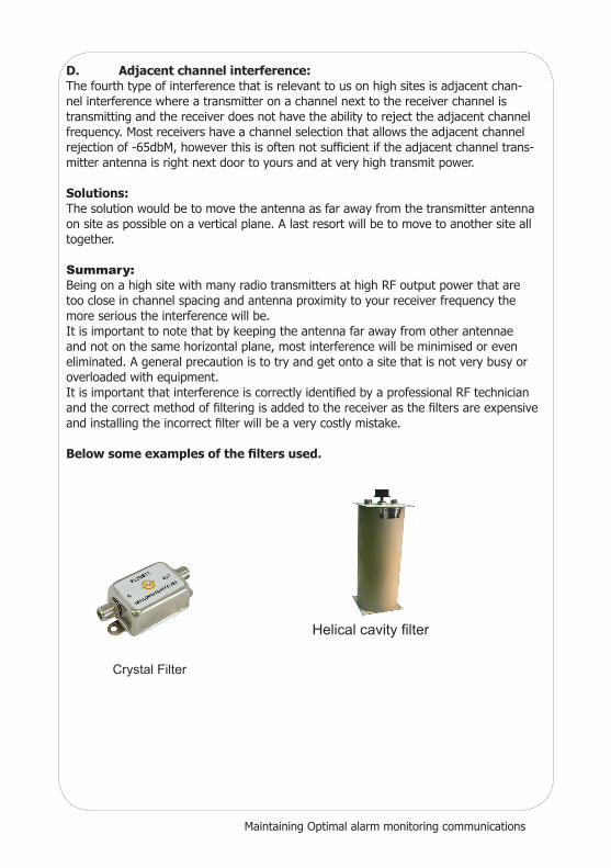
Belowsomeexamplesofthefiltersused.
Crystal Filter
Helical cavity filter