main solenoid and corrector - brookhaven national laboratory · keyed support disc courtesy: a....
TRANSCRIPT

MAC-07 November 16, 20101Main Solenoid and Corrector Ramesh Gupta, SMD
Main Solenoid and CorrectorRamesh Gupta
Superconducting Magnet Division
Nov. 16, 2010
Electron Lens

MAC-07 November 16, 20102Main Solenoid and Corrector Ramesh Gupta, SMD
Requirements
1.
Maximum design field : 6 T –
Specified operating field range 1 T to 6 T 2.
Field errors, -1050 <z <1050 mm, 1-6 T : <6 x 10⁻³
3.
Fringe field : field along the beam path till RT solenoid > 0.3T–
Unique situation, unique solution 4.
Field straightness: ±50 micron in -1050 <z <1050 mm
Field straightness is the most critical and demanding requirement guides and determines the overall design
too risky for industry to take this jobwell beyond the normal construction errors
corrector magnets become integral part of the overall designmust have enough magnetic shielding to limit the influence of surrounding

MAC-07 November 16, 20103Main Solenoid and Corrector Ramesh Gupta, SMD
Superconducting Solenoid with Superconducting Correctors
•
Axial field straightness is achieved by compensating transverse field errors (from normal construction) with horizontal and vertical dipole correctors.
•
In earlier designs, corrector dipoles were “inside”
the solenoid and were made of high current density copper. Now they are moved “outside”
and are made with superconducting wire. Benefits:
Earlier design with warm correctors(inside the superconducting solenoid)
allows stronger correctors (earlier current density in copper was too demanding).
significantly reduces the solenoid coil i.d. 292 mm to 200 mm. This in turn reduces the stored energy and Lorentz forces, thus making it a bit less demanding.
MAC-07 November 16, 20104Main Solenoid and Corrector Ramesh Gupta, SMD
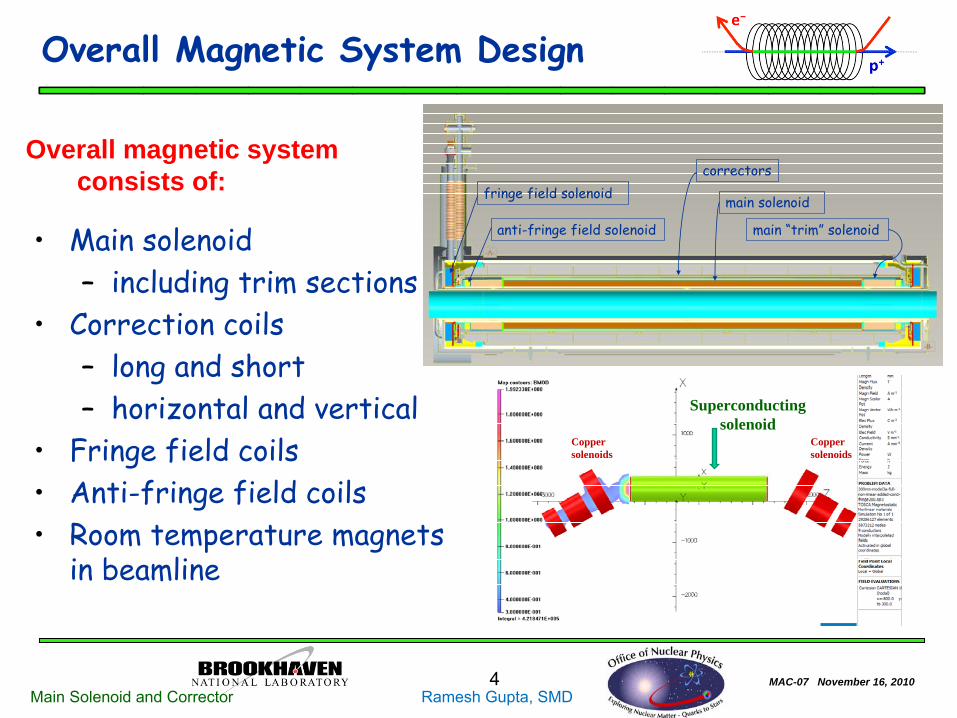
Overall Magnetic System Design
•
Main solenoid –
including trim sections
•
Correction coils–
long and short
–
horizontal and vertical•
Fringe field coils
•
Anti-fringe field coils•
Room temperature magnets in beamline
Copper solenoids
Superconducting solenoid
Copper solenoids
Overall magnetic system consists of: fringe field solenoid
anti-fringe field solenoid main “trim” solenoid
main solenoid
correctorsfringe field solenoid
anti-fringe field solenoid main “trim” solenoid
main solenoid
correctors

MAC-07 November 16, 20105Main Solenoid and Corrector Ramesh Gupta, SMD
6.0
6.2
6.4
6.6
6.8
7.0
7.2
7.4
7.6
7.8
8.0
400 420 440 460 480 500 520 540 560 580 600 620
Fiel
d (T
)
Current (A)
g p
[email protected] KWire Spec: 700A@7T,4.2K
Peak Field on Conductor
Central Fieldin Magnet
Temp Bss Bpk I(A)4.2 K 7.1 T 7.65 T 545 A4.5 K 6.8 T 7.35 T 523 A
Max. Design Field:6 Tesla
Computed Magnet Performance:
Field [email protected] K: ~13%
Stored Energy: ~1.4 MJ, Inductance:~14 Henry
E-lens Solenoid Wire and Magnet Performance
MAC-07 November 16, 20106Main Solenoid and Corrector Ramesh Gupta, SMD
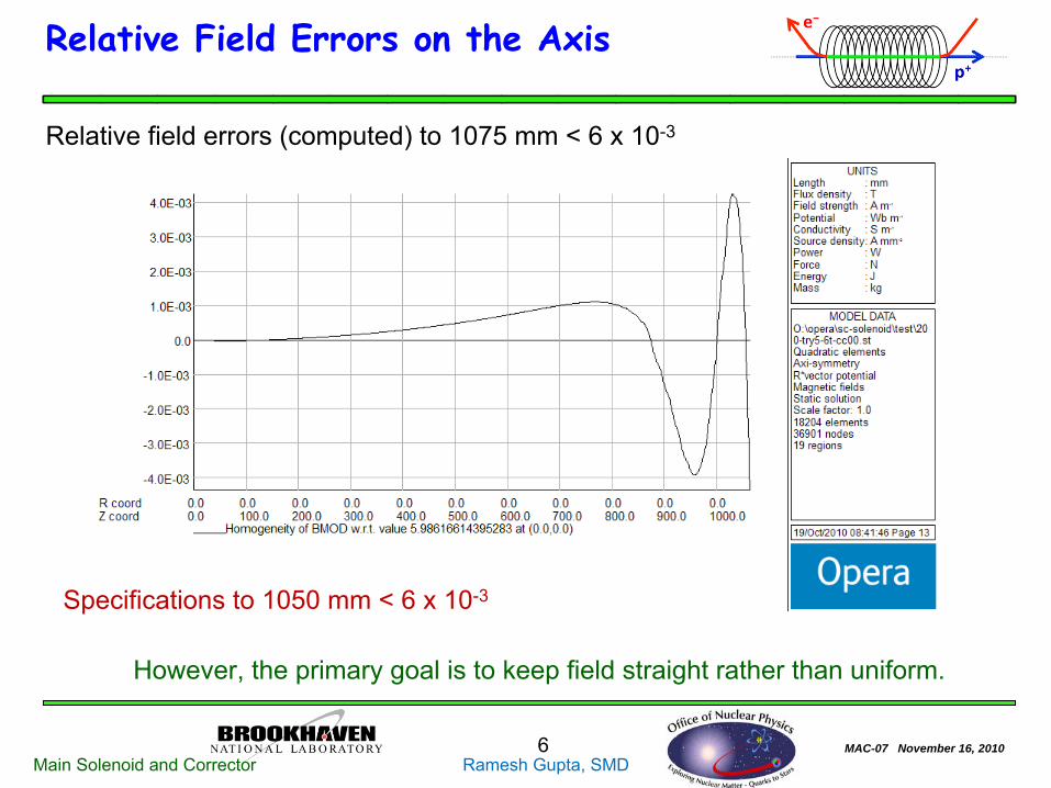
Relative Field Errors on the Axis
Relative field errors (computed) to 1075 mm < 6 x 10⁻³
Specifications to 1050 mm < 6 x 10⁻³
However, the primary goal is to keep field straight rather than uniform.
MAC-07 November 16, 20107Main Solenoid and Corrector Ramesh Gupta, SMD
Corrector Design

MAC-07 November 16, 20108Main Solenoid and Corrector Ramesh Gupta, SMD
Design Considerations for correctors
•
For e-lens to work, proton and electron beams must be aligned within ±50 micron.
•
Proton beam is aligned to the solenoid axis with long (full length) horizontal and vertical correctors. The maximum strength 0.006 T (more possible).
•
Electron field follows the solenoid magnetic axis. However, the tube on which the solenoid is wound can’t be perfect, and the coil winding can’t be perfect either. Moreover, the weight of the coil will also cause
some sag. •
Therefore, many short correctors are needed to achieve the desired straightness magnetically.
•
The strength (0.02 T, more possible) and number of short correctors (five horizontal and five vertical) is chosen based on estimated errors.
•
One must also deal with the field from the components in the surrounding area with sufficient thickness of iron shield over the solenoid coil.

MAC-07 November 16, 20109Main Solenoid and Corrector Ramesh Gupta, SMD
Estimation and correction of axis offset with 0.02 T correctors
-0.20
-0.15
-0.10
-0.05
0.00
0.05
0.10
0.15
0.20
0.25
-1400 -1000 -600 -200 200 600 1000 1400Axial Position (mm)
Sole
noid
Cen
ter
(mm
)
4 axial harmonicsλ = 0.5, 1, 2, 4 m0.1 mm amplitudesAll in phase
Comparable to what may be expected for an as-built solenoid.
-0.0050
-0.0040
-0.0030
-0.0020
-0.0010
0.0000
0.0010
0.0020
0.0030
0.0040
0.0050
-2000 -1500 -1000 -500 0 500 1000 1500 2000Axial Position (mm)
Tra
nsve
rse
Fiel
d (T
esla
)
UnCorrected3 strongest modes zeroed5 strongest modes zeroed
Computed Profile of Vertical Field, By
Hypothetical Vertical Offset Profile (before correction)
-0.200
-0.150
-0.100
-0.050
0.000
0.050
0.100
0.150
0.200
-1250 -1000 -750 -500 -250 0 250 500 750 1000 1250Axial Position (mm)
Sole
noid
Cen
ter
(mm
) UnCorrected3 strongest modes zeroed5 strongest modes zeroed
It is estimated that a system of 5-6 correctors should be able to reduce axis offsets to < ±50 μm, starting with offsets ~ ±0.2 mm.
Computed Axis Offset Profile
Afte
r cor
rect
ion
Courtesy: Animesh Jain

MAC-07 November 16, 201010Main Solenoid and Corrector Ramesh Gupta, SMD
Field on the Corrector
• Correctors will be placed outside the solenoid• They reside in a low field region (<1% of 6T)• This helps significantly:
Large margin in the superconductorLower Lorentz forces
MAC-07 November 16, 201011Main Solenoid and Corrector Ramesh Gupta, SMD
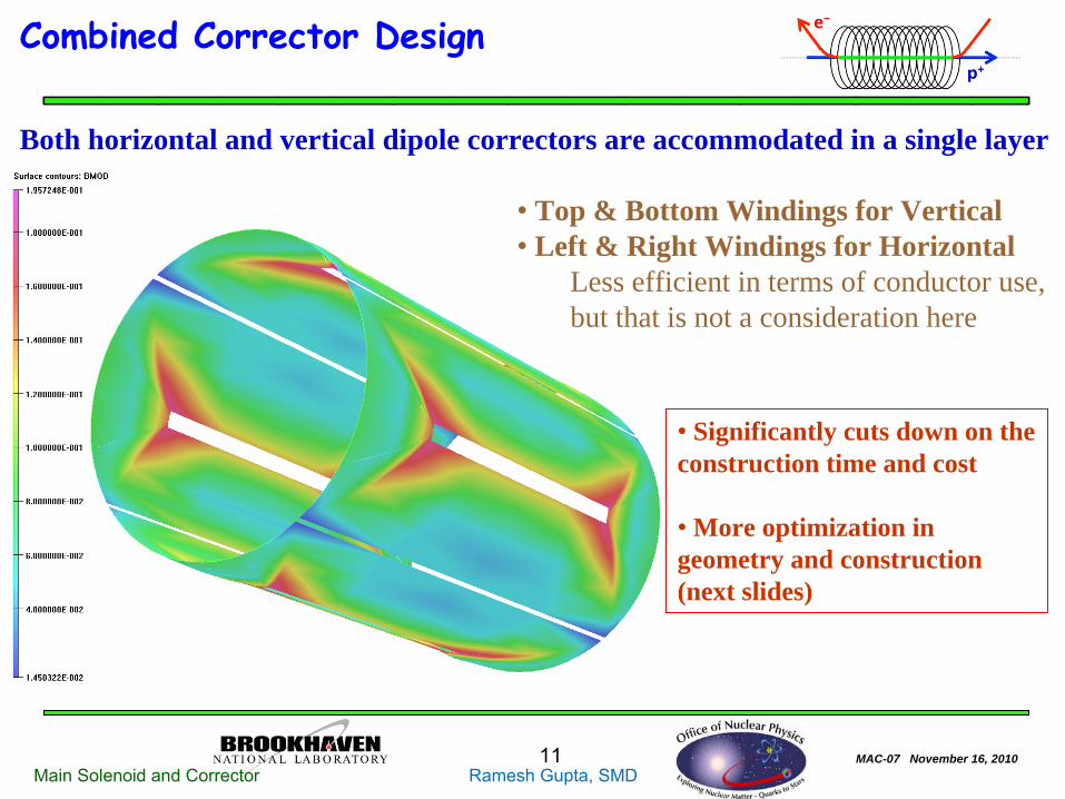
Combined Corrector Design
Both horizontal and vertical dipole correctors are accommodated in a single layer
• Top & Bottom Windings for Vertical• Left & Right Windings for Horizontal
Less efficient in terms of conductor use, but that is not a consideration here
•
Significantly cuts down on the construction time and cost
•
More optimization in geometry and construction (next slides)

MAC-07 November 16, 201012Main Solenoid and Corrector Ramesh Gupta, SMD
Slotted Corrector Design
•
Slots are machined in an aluminum tube and superconducting wires are place in the slots.•
Horizontal and vertical correctors are placed in the same radial location.•
Slotted design removes significant conflict with other projects in the use of certain machine
+45 degree
-45 degree
Right side of the vertical corrector

MAC-07 November 16, 201013Main Solenoid and Corrector Ramesh Gupta, SMD
Maximum ~10% drop between two corrector from a flat (peak) field
Superimposition of Fields of Long and Many Short Correctors (Horizontal & Vertical)
Field of long corrector
Superimposition of fields of long and short correctors
0.02
0.014
0.01
-0.025
MAC-07 November 16, 201014Main Solenoid and Corrector Ramesh Gupta, SMD
Exterior Field Requirements
MAC-07 November 16, 201015Main Solenoid and Corrector Ramesh Gupta, SMD
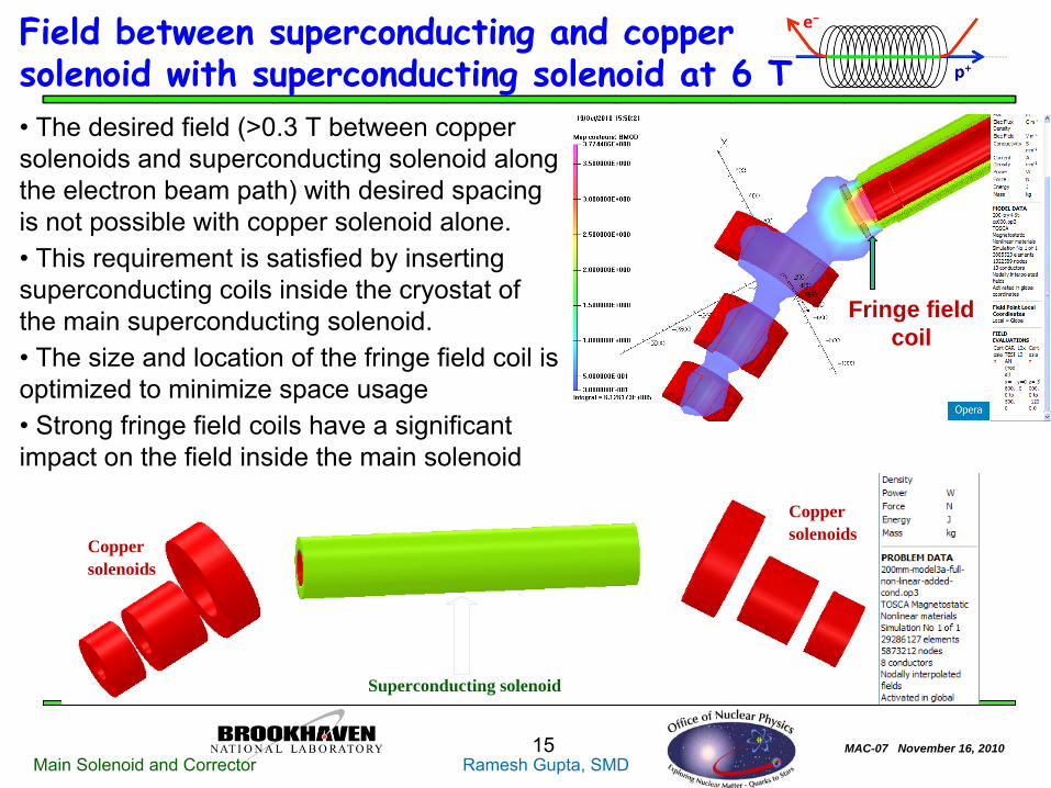
Field between superconducting and copper solenoid with superconducting solenoid at 6 T•
The desired field (>0.3 T between copper solenoids and superconducting solenoid along the electron beam path) with desired spacing is not possible with copper solenoid alone.•
This requirement is satisfied by inserting superconducting coils inside the cryostat of the main superconducting solenoid. •
The size and location of the fringe field coil is optimized to minimize space usage•
Strong fringe field coils have a significant impact on the field inside the main solenoid
Fringe field coil
Copper solenoids
Superconducting solenoid
Copper solenoids

MAC-07 November 16, 201016Main Solenoid and Corrector Ramesh Gupta, SMD
Field between superconducting and copper solenoid with superconducting solenoid <6 T
•
However, the situation becomes complicated when the main solenoid is operated at a field lower than 6 T –
the desired range is field as low as 1 T. •
In this case the outside field becomes significantly smaller because (a) the leakage field from the main solenoid becomes lower and (b) exterior field from the fringe field coil also becomes lower if it scales with the main solenoid to maintain field quality.•
To obtain desired the desired (>0.3 T) field between copper solenoids and the superconducting solenoid, the fringe field must run at full power.•
To obtain the required field quality, an additional coil (anti-fringe field coil) is added and powered independently to adjusted field quality.
Fringe field coilAnti-fringe field coil
Main solenoid @3 T
Fringe field coil Anti-fringe field coil
Main solenoid @1 T
MAC-07 November 16, 201017Main Solenoid and Corrector Ramesh Gupta, SMD
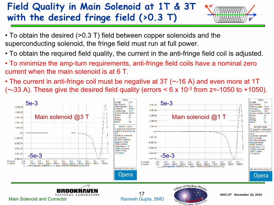
Field Quality in Main Solenoid at 1T & 3T with the desired fringe field (>0.3 T)
•
To obtain the desired (>0.3 T) field between copper solenoids and the superconducting solenoid, the fringe field must run at full power.• To obtain the required field quality, the current in the anti-fringe field coil is adjusted.•
To minimize the amp-turn requirements, anti-fringe field coils have a nominal zero current when the main solenoid is at 6 T. •
The current in anti-fringe coil must be negative at 3T (~-16 A) and even more at 1T (~-33 A). These give the desired field quality (errors < 6 x 10⁻³
from z=-1050 to +1050).
Main solenoid @3 T Main solenoid @1 T
5e-3 5e-3
-5e-3 -5e-3

MAC-07 November 16, 201018Main Solenoid and Corrector Ramesh Gupta, SMD
Quench Protection
E-Lens Main Solenoid Temp vs MIITS
y = 675.7x4 + 286.36x3 + 351.39x2 + 291.83x + 25.899R2 = 1
0
200
400
600
800
1000
1200
1400
1600
0.00 0.20 0.40 0.60 0.80 1.00MIITS
Tem
pera
ture
(K)
Calculated ValuesPoly. (Calculated Values)
Energy extraction and quench protection diodes are used to control temperature rise in the coil in the event of a quench
Total MIITs
in the circuit:
∫
I2
dt
: ~1.5 MIITs
(for I=~500 A, L=~14 H, Rdump
=~1.2 Ω;giving time constant: ~
τ= ~12 sec)
Diodes are across segments of the coil to limit the energy deposited in the coil segment ( < 0.5 MIITs).
Bus & diodes are designed to handle a much higher MIITs
than the coil conductor
(> 1.5 MIITs).
Energy extraction is used to limit the maximum MIITs
in the bus & diodes
Keep temperature < 350 K (0.5 MIITs)
This is safe as temperature remains well below 350 K Courtesy Joe MuratoreGeorge Ganetis
MAC-07 November 16, 201019Main Solenoid and Corrector Ramesh Gupta, SMD
Mechanical Analysis
MAC-07 November 16, 201020Main Solenoid and Corrector Ramesh Gupta, SMD
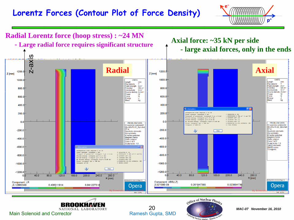
Lorentz Forces (Contour Plot of Force Density)
Radial Lorentz force (hoop stress) : ~24 MN- Large radial force requires significant structure
Radial Axial
Axial force: ~35 kN per side- large axial forces, only in the ends
z-ax
is

MAC-07 November 16, 201021Main Solenoid and Corrector Ramesh Gupta, SMD
Radial Force Restraint
•
Outward pressure (hoop stress) from 24 MN Lorentz forces.•
Radial forces can be restrained by 6 mm of material stressed (hoop) to 40,500 psi with coil energized.
•
Resulting stress in support tube (pressure vessel) is 17,000 psi. Required strain for S.S. tube is 0.014.
•
S.S. Tube heated to 80 degree C will give the required interference.•
Tube has 10 mm radial taper.3 Segment Main Solenoid
5mm Stn. Stl. Tapered Compression Sleeve
Keyed Support Disc
Courtesy: A. Marone

MAC-07 November 16, 201022Main Solenoid and Corrector Ramesh Gupta, SMD
Axial force containment
Axial
• Insert structure towards the end of the coil to contain forces•
Coil is wound continuously through the end structure to keep axial forces contained throughout (during quench). •
The axial forces exerted by the outer solenoid sections are transferred around the center section.•
The keyed support discs transfer the load to the support tube and the compression sleeve.
Structure for containing large axial force
3 Segment Main Solenoid
5mm Stn. Stl. Tapered Compression Sleeve
Keyed Support Disc
Courtesy: A. Marone

MAC-07 November 16, 201023Main Solenoid and Corrector Ramesh Gupta, SMD
Summary
This is a demanding magnet system with unique challengesMagnet aperture is large with significant stored energy and Lorentz forcesThe field should be very straight inside the magnet and the field magnitude
should be large outside the magnet In addition, significant effort is made to keep cost low and schedule accelerated
The following major steps have been taken to meet various requirements: • Novel and robust cryo-mechanical structure is developed (details not discussed)•
Corrector magnets are made superconducting and compact (H&V together) to reduce size, stored energy and Lorentz forces in the superconducting solenoid• A corrector design is developed that to facilitate the required field straightness•
Significant work is being done in magnetic measurement area (not discussed here) to assure that straightness•
Superconducting fringe field and anti-fringe coils have been added to obtain the large field outside while maintaining good field quality inside for 1 T to 6 T range.

MAC-07 November 16, 201024Main Solenoid and Corrector Ramesh Gupta, SMD
Extra slides

MAC-07 November 16, 201025Main Solenoid and Corrector Ramesh Gupta, SMD
Project Scope
Design, Build and Test 2 eLens
Solenoid Magnets:
•
Magnetic, mechanical, electrical requirements as specified by C/AD •
Conduct ongoing communications & meetings to significantly clarify scope, improve design and performance
•
Maintain cost control •
Deliver by April 2012
Courtesy: M. Anerella
MAC-07 November 16, 201026Main Solenoid and Corrector Ramesh Gupta, SMD
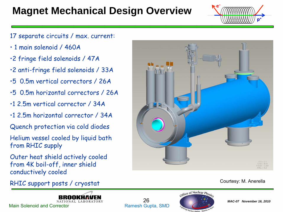
Magnet Mechanical Design Overview
17 separate circuits / max. current:
• 1 main solenoid / 460A
•2 fringe field solenoids / 47A
•2 anti-fringe field solenoids / 33A
•5 0.5m vertical correctors / 26A
•5 0.5m horizontal correctors / 26A
•1 2.5m vertical corrector / 34A
•1 2.5m horizontal corrector / 34A
Quench protection via cold diodes
Helium vessel cooled by liquid bath from RHIC supply
Outer heat shield actively cooled from 4K boil-off, inner shield conductively cooled
RHIC support posts / cryostat Courtesy: M. Anerella
MAC-07 November 16, 201027Main Solenoid and Corrector Ramesh Gupta, SMD
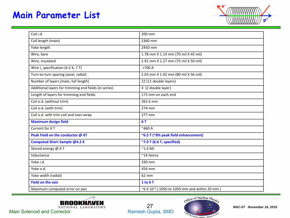
Main Parameter List
Coil i.d. 200 mm
Coil length (main) 2360 mm
Yoke length 2450 mm
Wire, bare 1.78 mm X 1.14 mm (70 mil X 45 mil)
Wire, insulated 1.91 mm X 1.27 mm (75 mil X 50 mil)
Wire Ic
specification (4.2 K, 7 T) >700 A
Turn‐to‐turn spacing (axial, radial) 2.03 mm X 1.42 mm (80 mil X 56 mil)
Number of layers (main, full length) 22 (11 double layers)
Additional layers for trimming end fields (in series) 4 (2 double layer)
Length of layers for trimming end fields 173 mm on each end
Coil o.d. (without trim) 262.6 mm
Coil o.d. (with trim) 274 mm
Coil o.d. with trim coil and over‐wrap 277 mm
Maximum design field 6 T
Current for 6 T ~460 A
Peak Field on the conductor @ 6T ~6.5 T (~8% peak field enhancement)
Computed Short Sample @4.2 K ~7.0 T (6.6 T, specified)
Stored energy @ 6 T ~1.4 MJ
Inductance ~14 Henry
Yoke i.d. 330 mm
Yoke o.d. 454 mm
Yoke width (radial) 62 mm
Field on the axis 1 to 6 T
Maximum computed error on axis ~6 X 10‐3
(‐1050 to 1050 mm and within 20 mm )

MAC-07 November 16, 201028Main Solenoid and Corrector Ramesh Gupta, SMD
Dimensions
•
Yoke length 96.5 inches (~2.5 m)•
Yoke OD 17.9 inches
•
Cold mass length 104.7 inches•
Cold mass OD 19.5 inches
•
Magnet OD 24.0 inches•
Magnet length 110.6 inches
•
Magnet weight ~7000 lbs.
20 October 2010Stephen Plate 28
Courtesy: S. Plate
MAC-07 November 16, 201029Main Solenoid and Corrector Ramesh Gupta, SMD
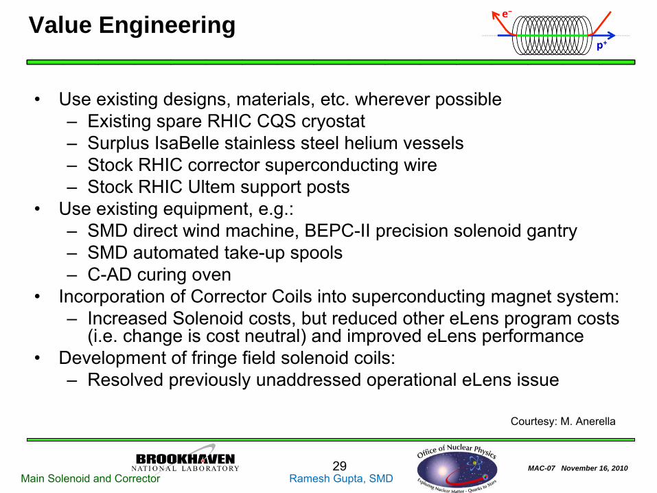
Value Engineering
•
Use existing designs, materials, etc. wherever possible–
Existing spare RHIC CQS cryostat–
Surplus IsaBelle
stainless steel helium vessels–
Stock RHIC corrector superconducting wire–
Stock RHIC Ultem
support posts•
Use existing equipment, e.g.:–
SMD direct wind machine, BEPC-II precision solenoid gantry–
SMD automated take-up spools–
C-AD curing oven•
Incorporation of Corrector Coils into superconducting magnet system:–
Increased Solenoid costs, but reduced other eLens
program costs (i.e. change is cost neutral) and improved eLens
performance•
Development of fringe field solenoid coils:–
Resolved previously unaddressed operational eLens
issue
Courtesy: M. Anerella

MAC-07 November 16, 201030Main Solenoid and Corrector Ramesh Gupta, SMD
Fringe & Anti Fringe Coils
Fringe Coil
Anti Fringe Coil
Fringe Coil
Anti Fringe Coil
Fringe Coil
Anti Fringe Coil
•
Fringe–
40,000 lbs. axially inward (toward main Solenoid).
–
2000 psi radially
outward (@ O.D. of coil)
•
Anti Fringe–
15,000 lbs. axially outward (toward fringe coil).
–
225 psi radially
inward
Courtesy: A. Marone

MAC-07 November 16, 201031Main Solenoid and Corrector Ramesh Gupta, SMD
Project Team
•
Project / Engineering Supervision –
Mike Anerella•
Scientist, Magnetic Design –
Ramesh Gupta
•
Mechanical Engineer, Magnet –
Steve Plate
•
Mechanical Engineer, Coils –
Andy Marone
•
Mechanical Engineer, Design –
Paul Kovach
•
Electrical Engineer, Coils –
John Escallier
•
Electrical Engineer, Tooling –
Piyush
Joshi•
Scientist, Magnetic Measurements –
Animesh Jain•
Scientist, Cold Test –
Joe Muratore
Many other experienced SMD personnel involved at some level Courtesy: M. Anerella