main features - novationmusic.com · main features thank you for purchasing the novation v-station...
TRANSCRIPT

Main Features
Thank you for purchasing the Novation V-Station software synthesizer.
The V-Station virtual analogue synthesizer recreates the power and rich sound of the K-Stationsynth as a plug-in for Macintosh or Windows.
At the core of the V-Station is Novation’s ‘Liquid Analogue’ synthesis engine, delivering rich,dense sounds that offer vast creative potential. The plug-in combines these with a clear andresponsive front panel interface with all the key sound shaping controls you need.
Main features• 3 audio oscillators deliver a wide range of waveforms.
• Noise generator authentically models analogue noise generator circuits.
• Ring modulator for clangy, bell-like textures.
• FM synthesis for the accurate creation of electric pianos and tuned percussion sounds.
• 5-channel mixer for combining and balancing the oscillators, noise generator and ringmodulator.
• Resonant ‘Liquid Analogue’ lowpass filter with 12dB/Octave and 24dB/Octave settings.
• 2 x ADSR envelope generators.
• 2 x multi-wave, MIDI syncable LFOs.
• Portamento with exponential and linear slopes.
• Unison mode puts all eight voices (with detune) on one note for a huge sound.
• Arpeggiator with variable patterns, range and gate time. MIDI syncable to host sequencer.
• 6 x simultaneous multi-effects including delay (echo), reverb, chorus/flanging/phasing,EQ, distortion and panning.
• Multiple instances in your sequencer host 1
• Transfer sounds to/from a K-Station.
• Easy to use ‘knobby’ panels that emulates a hardware synth.
• 400 memory locations (200 factory presets / 200 user presets).
1 The exact number of instances depends on your computer’s processing power. Naturally, thefaster the CPU, the more instances you can use simultaneously.
1 Introduction

Minimum Requirements
Minimum requirements
OPERATING SYSTEMS - PC
Windows 98SE - 98MEWindows 2000 (Service Pack 3)WindowsXP
HARDWARE
Pentium III 1GHz (or equivalent Athlon)256MB RAM or more
SEQUENCER HOSTS
LOGIC V5.5SONAR 1.3.1 (minimum) and a suitable VSTi > DXi adapter. (e.g., DirectiXer 2.3)CUBASE SX Version 1.05.58
-------------------------------------------------------------
OPERATING SYSTEM - Apple Macintosh
MAC OSX V10.2.4
HARDWARE
450MHz G3 / G4256MB RAM
SEQUENCER HOST
LOGIC V 5.5
-------------------------------------------------------------
And as they always say.....
Or greater / higher.
Copyright notice: 'VST’ is a trademark of Steinberg Media Technologies GmbH
2 Introduction

Using the V-Station
Installing the V-Station - Apple MacintoshInsert the CD-ROM into your computer’s CD-ROM drive and locate the file ‘V-Station.dmg’.
Double click on the file ‘V-Station.dmg’ - this will open as a .pkg file. Double click on this andsimply follow the on-screen instructions. At the end of the installation process, you will beprompted to finish - click on QUIT.
Note : You may need to restart your computer after the installation.
The V-Station audio unit is now installed. However, you will need to authorise your copy. This isdone when you come to insert the V-Station into a track for the first time. More on this later.
Note : The V-Station only runs under OSX. It cannot be installed on a Mac running OS9 orearlier.
Installing the V-Station - Microsoft WindowsInsert the CD-ROM into your computer’s CD-ROM drive. The installation program should startautomatically when you insert the CD-ROM. If this doesn't happen, locate the file ‘setup.exe’.
Double click on this and simply follow the on-screen instructions. At the end of the installationprocess, you will be prompted to finish - click on QUIT.
The V-Station audio unit is now installed. However, you will need to authorise your copy. This isdone when you come to insert the V-Station into a track for the first time. More on this later.
Note : You should select the correct "VstPlugins" directory for your sequencer.
Most VST applications require you to install VST plug-ins into a specific folder for theapplication in question. You should ensure that the correct directory/folder is selected. Thedefault selection should be correct but may not be if you have changed the location of yourplug-ins folder.
If you want to use the V-Station in more than one VST application, you will have to manuallycopy the ‘vstation.dll’ file which has already been installed from the default application’s plug-ins folder into the other VST application’s plug-ins folder.
For example, if you plan to use the V-Station in Cubase and Logic and you install the V-Stationinto Cubase’s plug-ins folder, you will have to manually copy the file ‘vstation.dll’ into Logic’sVstplugins folder for it to be used in that application.
However, whilst some VST applications require their plug-ins to be in very specific folders,others use the concept of ‘shared’ plug-ins folders that can be used across a variety of differenthosts from the same vendor.
Frankly, there is no one standard and if you plan to use the V-Station in other VST compatibleapplications, you should refer to each of the particular application’s operator’s manual for detailson where the plug-in should be installed.
Inserting the V-Station into a trackTo insert the V-Station into a track, you should consult your sequencer’s operator’s manualwhere it will tell you what you need to do. Each sequencer handles this differently and it isalmost impossible to explain every variation on the process here.
3 Getting Started

Using the V-Station
Authorising your copy of V-StationBefore you can use the V-Station, you need to authorise it with an unlocking code that isunique to you and your computer and plug-in.
To obtain your unlocking code, make a note of the MACHINE CODE shown in the AUTHORISEdialogue (or drag over and copy it). You can close the AUTHORISE window for now.
Now visit the following URL:
http://www.novationmusic.com
Locate the V-Station registration link. You will see a form which you must complete. Fill indetails such as name and address, etc.. You will also need to enter your V-Station’s serialnumber which can be found in the CD-ROM’s packaging. These are required so that we have arecord of your product registration. You will also be asked to enter your email address - this isrequired for us to send you the unlocking code.
You should now enter the MACHINE CODE in the appropriate box. You should also enter aUSER NAME. Fill in any other entries that are required and click on the SUBMIT button.
Shortly afterwards, you will receive your UNLOCKING CODE via email.
Copy this unlocking code and, in your sequencer, insert the V-Station again. Once again, youwill receive the AUTHORISE dialogue. Paste the UNLOCKING CODE into the KEYCODE boxand click on DONE. The V-Station will now launch and you can use it. Once authorised, you willnot receive the authorisation dialogue again and you are free to use your V-Station.
Note : The UNLOCKING CODE is tied to your computer’s machine code and your machinecode is unique to your computer. If you want to move the V-Station to another computer or ifyou upgrade your computer, you will need to re authorise.
Please keep your unlocking safe just in case of unforeseen eventualities - best to write it downon paper in case of the worst scenario, a complete disk crash.
Soundcard settingsThe minimum setting for successful operation of the V-Station with your soundcard is for44.1khz/16-bit operation. The V-Station will work perfectly well at settings higher than this but itmay place unnecessary strain on your computer. However, please note that with settings lowerthan 44.1kHz/16-bit, you will experience problems with performance and, in particular, soundquality.
Using this manualThis manual consists of several chapters: Introduction, Getting Started, a Synthesis Tutorialand then detailed descriptions of the functions found on each of the V-Station’s panels. Foreasy reference, the chapter name is printed in the footer margin of each page.
If you plan to print this manual out, it is designed for single face printing and the left of the pagehas a wide margin to accommodate a hole punch for inserting into a ring folder.
It is recommended that this manual is read in sequence chapter by chapter. If sound synthesisis an unfamiliar subject, then the Synthesis Tutorial will provide a useful introduction to thetechniques used to create sounds using an analogue music synthesizer.
If you are familiar with synthesis techniques, you can skip to the various ‘operation’ chaptersthat describe each control and switch in detail.
The screen shots used throughout this manual are principally from a Mac running OSX. Whilstsome of the windows and prompts may look different to those found on a PC and the variousflavours of Windows, their operation is basically the same.
4 Getting Started

Using the V-Station
Using the V-StationIf you are already familiar with analogue synthesizers and VSTi / Audio Unit plug-ins, you canprobably get started immediately. The most important parameters are on the MAIN panel butother, lesser used functions can be found on sub-pages EXTRA, CONTROLS and GLOBAL.These are accessed by clicking on the buttons at the top right of the window and should befairly self-explanatory. Further details regarding operation of these panels are included later inthis operator’s manual.
Selecting programsProbably the best way to get a feel for the V-Station is to play the factory presets that aresupplied.
The V-Station comes supplied with 400 program memory locations of which the first 200 areoccupied with factory presets. These presets can be selected and auditioned simply byclicking on the PROGRAM up/down buttons to the left of the LCD in the bottom left of thewindow. It is worthwhile going through these to get a feel for the sounds the V-Station iscapable of. Amongst them you will find a wide range of synth basses, pads, arpeggiators andother dramatic sounds to get you started.
It is also possible to select sounds using your computer’s numeric keypad - simply type in athree digit number (100-400) to select a specific program number.
To select sounds using your computer keyboard’s numeric keypad, the NUMPAD PROGRAMSELECT preference must be enabled in the GLOBAL page.
Note : Some sequencers use the numeric keypad for play, stop, locating and other functions.Some sequencers allow you to re-assign these so that you can use the keypad for otherpurposes. Others, however, do not. If your sequencer doesn’t allow you to re-assign thenumeric keypad, you won’t be able to select programs numerically. You should switchNUMPAD PROGRAM SELECT off.
Editing soundsThe V-Station’s panel(s) can be edited much like the K-Station’s real panel - not quite as directperhaps as reaching out and tweaking a knob but....
Simply move your mouse over the control you want to change. On the Mac, the cursor willchange to a ‘hand’ and on a PC, the cursor will change to a ‘cross-hair’ symbol. The selectedparameter and its value will be shown on the LCD:
Click on the control and move the mouse up or down. As the control is moved, the valuechanges in the display. You will also note that ‘LEDs’ around the control will illuminate to giveyou visual feedback of the control’s setting as it is adjusted.
Switches can be enabled / disabled simply by clicking on them. Also, some selections such asoscillator and LFO waveforms, oscillator octave, filter slope, effects selection, etc., are selectedby clicking on their LEDs directly:
5 Getting Started

Using the V-Station
Other parameters such as those shown below are set by selecting an item from a drop downmenu:
Click and hold on these and make your selection by dragging down the drop down list andreleasing the mouse on the value you want to set.
Note : If you have a mouse that is equipped with a wheel, you can use this to great effect withthe panels. When the cursor is over a knob or slider, simply use the wheel to move it and set avalue - no need to click... just place the cursor over the control and scroll the mouse wheel.
The mouse wheel can also be used with drop down menus as well... place the mouse over adrop down and scroll.
Using the COMPARE functionAfter making any changes to a sound it may be useful to compare it with the originally storedprogram.
To illustrate this, select any program and tweak the panel controls - move the filter, change anoscillator’s octave setting, whatever. Now click and hold down the COMPARE button. Thesound you will hear will now be the originally stored program. Releasing the COMPARE buttonwill switch to listening to the edited sound again. In this way, you can decide whether thechanges you have made are worthwhile or should be abandoned
Writing a programIf you make a change to a sound that you like, the chances are that you will want to keep it foruse later on. Sounds may be saved in any memory location. However, it is recommended thatthe user locations (300 - 499 ) are used early on for saving new sound creations if only toprevent losing the original factory presets (but if you are confident enough to overwrite thefactory presets with your own creations, feel free... it’s up to you to decide!).
The factory preset sounds are in locations 100 to 299 and may be overwritten if desired. Oncethese factory presets are overwritten, they may only be retrieved by performing a factoryrestore.
To actually save the sound, click on the WRITE button below the LCD. The display will promptyou to select a memory location:
6 Getting Started

Using the V-Station
If you want to over-write the existing sound, simply click on CONFIRM - the sound will be writtento the current location.
Note : The destination memory is always initially set to the currently selected program’snumber. Take care not to accidentally overwrite a treasured preset!
If you want to save the sound in a different location (thereby retaining the original sound in itsoriginal location), using the PROGRAM up/down buttons, select the destination memory andclick on CONFIRM.
To cancel the WRITE operation, simply click on WRITE again.
Loading and saving banksMost sequencer hosts allow you to load and save banks of sounds. This is useful if you want tocreate your own library of sounds and you could, for example, create a set of, say, ‘techno’sounds on your V-Station - these could be saved as a bank named “Techno”. You might alsocreate a series of ‘vintage’ synth emulations - again, these could be saved as a bank called“Vintage”. Whatever... you can subsequently load all these sounds back into your V-Station atany time. In this way, you can build up your own private library of V-Station sounds. It’s alsolikely that banks of sounds will appear on the Internet which can be downloaded and used withyour V-Station.
You should consult your sequencer’s documentation for details on loading and saving banks.
Note : We have used the term ‘bank’ to describe a collection of sounds that can be loaded /saved on a plug-in. Different sequencers use different terminology for the same thing.
Notes about loading and saving generallyThere are generally three ways to load and save items within your sequencer and to confusethe issue, different sequencers either deal with this differently and/or use their ownterminology for what is basically the same process!
At the top level, you can save your song. This will not only save the music you have recordedbut it will also save the current settings of the V-Station (and any other plug-in(s) you may haverunning). When you subsequently load that song, the V-Station’s sound(s) will also berecalled. Even if you have edited a sound, the edited version will be recalled when the song isopened again.
At the next level, you can save (or ‘write’) individual sounds to the V-Station’s ‘internal’ memory.Thus, whenever you use the V-Station in any song, the sounds you have edited / created canbe used in that song.
However, once you start building up lots of sounds of your own creation, you can save theseas a bank (or or ‘preset’ or ‘setting’ or whatever it is your sequencer calls them) and these canbe loaded into the V-Station quite separately from the song. To illustrate this, you could beworking on a song but can’t find the right sound. You can load a different bank of sounds intothe V-Station where you have access to 400 different sounds.
Some sequencers also allow you to save single sounds and these can subsequently beloaded into the V-Station at a later date.
Don’t be confused by all of this, however - most of the time, you will simply insert instances ofthe V-Station into your song, select sounds as required (maybe even tweak them to suit thesong) and then you’ll just save the song’s sequence file. When you load that song again, theinstances of the V-Station will be recalled along with the sounds you selected / edited. TheWRITE and SAVE / LOAD BANK (or whatever) options are more for building up a library of yourown sounds.
7 Getting Started

Elements of a Sound
Elements of a soundTo gain an understanding of how a synthesizer generates sound, it is helpful to have anunderstanding of the components that make up a sound, be it musical or non-musical.
The only way that a sound may be detected is by air vibrating the eardrum in a regular, periodicmanner. The brain interprets these vibrations (very accurately) into one of an infinite number ofdifferent types of sound.
Remarkably, any sound may be described by just three elements, and all sounds always havethem. They are :
* Volume* Pitch* Tone
What makes one sound different to another is the proportion of these three qualities initiallypresent in the sound and how these three terms change throughout the duration of thesound.
With a musical synthesizer, we deliberately set out to have precise control over these threeelements and, in particular, how they can be changed throughout the duration of the sound.These elements are often given different names: volume is sometimes referred to as amplitudeand/or level, pitch as frequency and tone as timbre.
PitchTaking the example of air vibrating the ear drum, pitch is determined by how fast the vibrationsare. For an adult human the lowest vibration perceived as sound is about twenty times asecond, which the brain interprets as a low, bass type sound and the highest is manythousands of times a second which the brain interprets as a high pitched sound.
Wave A
Wave B
If the number of peaks in the two waveforms (vibrations) are counted, it will be seen that thereare exactly twice as many peaks in Wave B as there are in Wave A. (Wave B is actually an octavehigher in pitch than Wave A). It is the number of vibrations in a given period that determines thepitch of a sound. This is the reason that pitch is sometimes referred to as frequency. It is thefrequency of the waveform peaks which are counted during a given period of time. Frequencyis expressed in Hertz (abbreviated to Hz). For example:
20Hz 20 Hz or 20 cycles per second
440Hz 440Hz or 440 cycles per second. This is also known as ‘concert A’ or ‘A-440’and is the pitch an orchestra tunes to. It is also the common tuning referencefor many other instruments.
1kHz 1,000Hz or 1,000 cycles per second
10kHz 10,000Hz or 10,000 cycles per second
8 Synthesis Tutorial

Elements of a Sound
ToneMusical sounds consist of several different related pitches occurring simultaneously. Theloudest is referred to as the ‘Fundamental’ pitch and corresponds to the perceived note of thesound. Pitches related to the fundamental are called harmonics (sometimes also referred to as‘overtones’) and these are multiples of the fundamental (i.e. x2, x3, x4, x5, x6..... etc.). Thenumber of harmonics and their relative loudness to the fundamental determines the tone or‘Timbre’ of the sound. Some waveforms contain both even and odd numbered harmonics (i.e.fundamental plus x2, x3, x4, x5... etc.), others contain only odd numbered harmonics(fundamental and x3, x5, x6, x7.... etc.). Some contain lots of harmonics (even and/or odd)whilst others only have a few.
Consider two instruments such as a clarinet and a trumpet playing exactly the same note atexactly the same volume. Even though the pitch and volume are identical, they soundcompletely different. This is because the trumpet is rich in even and odd harmonics whereasthe clarinet only contains odd numbered harmonics. Consider also a flute - another verydifferent tone. This is because a flute typically has very few harmonics. When a sound has a lotof harmonics, the sound will be bright; when a sound has very few harmonics, it will be mellowin tone.
However, tone is rarely static on most instruments and varies during the course of the note.Generally, sounds start off quite bright and, because higher harmonics have less energy, theytend to die away first followed by lower frequency harmonics - the result is that the soundgradually gets softer in tone throughout the note. Other instruments start off with fewharmonics but higher harmonics build up throughout the course of a note so that the soundgets gradually brighter. Tonal changes are often linked with level changes - i.e. the harder youhit, pluck, scrape or blow something, not only is it louder but it is usually brighter in tone.
VolumeVolume, which is referred to as the amplitude or loudness of the sound, is determined by howlarge the vibrations are. Think of a guitar string - pluck it softly so that it hardly vibrates and thesound will be low in level. Pluck it hard, however, so that it moves a lot and the sound will belouder.
In the diagram above, the waveform on the right is quieter than the one on the left.
However, volume is not a static element of a sound as it tends to change throughout a note’sduration. Consider the sound of a piano and, say, an oboe - the piano is initially very loud butdies away over time. The oboe, on the other hand, has a soft start but sustains during thecourse of the note (though not always). Other instruments’ amplitude varies in different ways aswell - some sounds start slowly (bowed instruments, for example) whilst other sounds ring onfor a long time after the note has sounded (a gong, for example). The way in which a soundvaries over time is known as the ‘envelope’ .
9 Synthesis Tutorial

Elements of a Sound
Putting it all togetherHaving shown that just three elements make up any sound, these elements now have to berelated to a musical synthesizer. It is logical that each element of the sound is handled bydifferent sections on a music synthesiser.
OSCILLATORS generate the basic waveforms which provide the pitch of the sound along withits raw harmonic content (tone). This passes into a section called the FILTER which isresponsible for further altering the tone of the oscillator’s basic waveform. It does this byremoving (filtering) certain undesired harmonics. Lastly, the filtered signal is fed into anAMPLIFIER which determines the final volume of the sound. The simplest synthesizer wouldlook something like this:
OSCILLATOR FILTER AMPLIFIER
However, additional synthesizer sections; LFOs (low frequency oscillators) and ENVELOPESprovide ways of altering the pitch, tone and volume of a sound by interacting with theoscillators, filter and amplifier. They introduce changes in the character of a sound that evolvethroughout the duration of the sound. Because the LFOs and Envelopes’ only purpose is tocontrol (modulate) the other synthesizer sections, they are commonly known as ‘modulators’. Amore advanced synthesizer might look like this:
OSCILLATOR FILTER AMPLIFIER
LFO ENVELOPE ENVELOPE
The oscillator generates the basic waveform but can be controlled (or modulated) from the LFOfor effects such as vibrato, etc.. The oscillator’s signal passes on to the filter where the basicwaveform can be modified further and the filter’s envelope can cause tonal changes to takeplace over time. Finally, the sound passes onto the amplifier where the sound’s envelope canbe shaped.
The V-Station’s sound generating process is all based around these basic principles exceptthat it has three oscillators which can be mixed and combined in any number of ways to providea far greater palette of raw waveforms than a single oscillator could ever produce. Theoscillators can also be detuned to create a denser sound (consider the sound of a single violincompared with a string ensemble where several violins are playing together but all slightlydetuned from each other).
These three oscillators are then mixed together in a mixer and the output of this mixer passesto the filter. The filter can be controlled by its own envelope but also by a separate LFO. Thesignal then passes through a final amplifier that can be shaped with its own envelope. On theV-Station, however, the output of the amplifier also passes through multi-effects where youcan add echo, reverb, chorus, etc., to add the final polish to the sound.
The various synthesizer sections will now be covered in more detail.
10 Synthesis Tutorial

Oscillators / Waveforms
OscillatorsThe oscillator is really the heartbeat of the synthesizer. It generates an electronic wave (whichcreates the vibrations). This waveform is produced at a controllable musical pitch, initiallydetermined by the note played on a keyboard or other MIDI controller. The initial distinctivetone or timbre of the waveform is actually determined by the wave’s shape.
Many years ago, pioneers of musical synthesis discovered that just a few distinctive wavescontained most of the useful harmonics for musical synthesis. The names of these wavesreflect their actual shape when viewed on an instrument known as an oscilloscope. They are:
WAVEFORM WAVESHAPE HARMONIC STRUCTURE
F
Sine wave
The sine wave contains no harmonics, just the fundamental frequency and is the purest soundavailable.
F 3
Triangle wave
5
The triangle wave is another pure sound but it does contain a few odd-numbered harmonics.
Square wave
F 3 5 7 9 11
The square wave is a very bright but hollow sounding waveform, not unlike the tone of aclarinet. It consists of a wide range of odd numbered harmonics.
On many synths (the V-Station included), it is possible to vary the width of the square wave:
The so-called ‘pulse’ waves at either extreme have a very different harmonic content to thesquare wave and sound ‘thinner’ and more ‘nasal’. However, because the pulse width is totallyvariable, the harmonic content of each variation in between the extremes also differs. If thepulse width is controlled by something like an LFO, a very vibrant and animated sound can becreated - this is called Pulse Width Modulation.
F 1 2 3 4 5 6 7 8 9 10
Sawtooth wave
11
The sawtooth wave is probably the brightest sounding waveform of all and contains a widerange of odd and even numbered harmonics in equal proportion. It is good for a wide range ofsounds including strings, brass and more.
11 Synthesis Tutorial
Oscillators / Waveforms
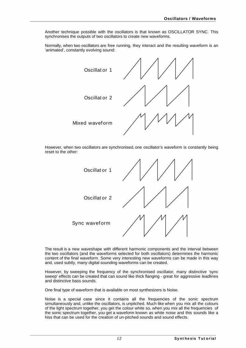
Another technique possible with the oscillators is that known as OSCILLATOR SYNC. Thissynchronises the outputs of two oscillators to create new waveforms.
Normally, when two oscillators are free running, they interact and the resulting waveform is an‘animated’, constantly evolving sound:
Oscillator 1
Oscillator 2
Mixed waveform
However, when two oscillators are synchronised, one oscillator’s waveform is constantly beingreset to the other:
Oscillator 1
Oscillator 2
Sync waveform
The result is a new waveshape with different harmonic components and the interval betweenthe two oscillators (and the waveforms selected for both oscillators) determines the harmoniccontent of the final waveform. Some very interesting new waveforms can be made in this wayand, used subtly, many digital sounding waveforms can be created.
However, by sweeping the frequency of the synchronised oscillator, many distinctive ‘syncsweep’ effects can be created that can sound like thick flanging - great for aggressive leadlinesand distinctive bass sounds.
One final type of waveform that is available on most synthesizers is Noise.
Noise is a special case since it contains all the frequencies of the sonic spectrumsimultaneously and, unlike the oscillators, is unpitched. Much like when you mix all the coloursof the light spectrum together, you get the colour white so, when you mix all the frequencies ofthe sonic spectrum together, you get a waveform known as white noise and this sounds like ahiss that can be used for the creation of un-pitched sounds and sound effects.
12 Synthesis Tutorial

Mixer / Noise Generator / Ring Modulator
MixerTo extend the range of sounds that may be reproduced, a typical analogue synthesizer oftenhas more than one oscillator. By using more than one oscillator when creating a sound, itpossible to achieve very interesting harmonic mixes. It is also possible to slightly detuneindividual oscillators against each other which creates a very warm ‘fat’ sound. The V-Stationhas three independent oscillators which can be mixed.
For flexibility, a mixer section is usually included so that the level of each of the oscillators maybe adjusted independently and mixed together to form a harmonically complex waveform.
However, as well as mixing together the individual oscillators, the V-Station’s mixer also allowsyou to adjust the relative volume levels of a Noise Generator and a Ring Modulator:
Oscillator 1
Oscillator 2
Oscillator 3
Mixer
Noise
Ring Mod
The Noise Generator produces an unpitched sound suitable for drums sounds, sound effects,etc..
The Ring Modulator is a device that takes two inputs and produces sum and differencefrequencies at the output. For example:
INPUT A: 500HzINPUT B: 750HzOUTPUT: 1.25kHz (1,250Hz - the sum) and 250Hz (the difference)
Typically, these sum and difference frequencies will be ‘enharmonic’ (i.e. not harmonicallyrelated to the frequencies presented at Inputs A and B) resulting in clangy, metallic, bell-likesounds.
The Ring Modulator also has a use as an octave divider. For example:
INPUT A: 440Hz (Concert A)INPUT B: 880Hz (An octave up)OUTPUT: 1.76kHz (1,760Hz - the sum a further octave up)
In this way, you can coax another octave out of the oscillators for a bigger sound.
The Ring Modulator on the V-Station always takes Oscillators 1 and 2 as its input sources asshown in the diagram above.
13 Synthesis Tutorial

Filter
FilterThe V-Station is an analogue subtractive type of music synthesizer. Subtractive implies thatpart of the sound is subtracted or removed somewhere in the synthesis process.
The oscillators provide the raw waveforms many of which have plenty of harmonic content andit is the filter that subtracts unwanted harmonics in a controllable manner.
The filter in the V-Station is a Low Pass type. A cut-off point is chosen and any harmonicsbelow that point are allowed to pass through unaffected and any above are filtered out. Thesetting of the FREQUENCY knob on the V-Station panel dictates the point below whichharmonics are removed. This process of removing harmonics from the waveforms has theeffect of changing the sounds character or timbre. When the FREQUENCY knob is set fullyclockwise, the filter is set completely open and no harmonics are removed from the rawoscillator waveforms:
Cutoff frequency
Here, all the harmonics pass through and the sound is very bright. However, as the control ismoved counter-clockwise, the cutoff frequency is reduced and the higher harmonics areremoved:
Cutoff frequency
In this example, all those harmonics within the shaded area pass through unaffected whilstthose above the cutoff frequency are removed and won’t be heard. With the cutoff set like this(i.e. about halfway), the sound will have mellower tone. As the cutoff moves down, so more andmore upper harmonics will be removed.
In practice, there is a gradual reduction in the volume of the harmonics above the cut-off point.How quickly these harmonics are reduced in volume above the cut-off frequency is determinedby the filter’s slope. This slope is measured in ‘volume units per octave’. Since Volume ismeasured in decibels, this slope is quoted in the number of decibels per octave (dB/Octave).Typical values are 12dB or 24dB per Octave. The higher the number, the faster the harmonicsare cut and the more pronounced the filtering effect.
12dB/Octave 24dB/Octave
Cutoff frequencyCutoff frequency
As you can see from the diagrams, the 12dB setting has a more gradual ‘slope’ than the 24dBsetting which is steeper and even though the CUTOFF is the same in both examples, moreupper harmonics are allowed to pass through with the 12dB setting than the 24dB setting.Some say that 12dB/Octave filters are ‘fizzier’ whilst the 24dB/Octave setting sounds‘punchier’ and more like the original analogue synths. The V-Station offers both types of filterslopes to be selected.
14 Synthesis Tutorial

Filter
A further important feature of the filter is the RESONANCE control. Frequencies at the cut-offpoint are increased in volume by this control:
Cutoff frequency
As you can see, those harmonics around the cutoff frequency are actually boosted in levelwhilst all those outside the shaded area are removed. This is useful for emphasising certainharmonics of the sound and with increased resonance settings, sweeping the cutofffrequency up and down causes the filter sound to change from the normal ‘waa’ sound to amore distinctive ‘weeow’ as the individual harmonics are picked out and emphasised.
As the RESONANCE is increased, a whistling like quality will be introduced to the soundpassing through the filter. When set to very high levels, RESONANCE actually causes the filterto self - oscillate whenever a signal is being passed through it. The resulting whistling tonebeing produced is actually a pure sine wave, the pitch of which depends on the setting of theFREQUENCY knob (the filter’s cut-off point). This resonance-produced sine wave can actuallybe used for some sounds as an additional sound source if desired.
15 Synthesis Tutorial

Amplifier / Envelopes
Amplifier and Mod envelopesIn earlier paragraphs, it was determined how the pitch and timbre of a sound is synthesised.This final part of the Synthesis Tutorial describes how the volume of sound is controlled. Thevolume throughout the duration of a sound created by a musical instrument often varies greatlyaccording to the type of instrument.
Note on Note off
Level
Time
An organ sound (above) quickly attains full volume when a key on the keyboard is pressed. Itstays at full volume until the key is released, at which point the volume level falls instantly tozero.
Note on Note off
Level
Time
A piano quickly attains full volume when a key is pressed and gradually falls back down to zeroafter several seconds, even if a key is held.
Note on Note off
Level
Time
A string section emulation attains full volume gradually (i.e. it swells in gracefully with a slowattack) when a key is pressed. It remains at full volume while the key is held down, but once thekey is released, the volume level gradually falls to zero.
On an analogue synthesizer, changes which occur throughout the duration of a note arecontrolled by a section known as an Envelope Generator.
Note that on the V-Station, there are no controls in a section on the MAIN panel which deal withthe amplifier directly. The only way to hear and control an audio signal passing through theamplifier is to modulate it by using Amp Envelope controls.
The V-Station has two envelope generators - one controls overall amplitude, the other controlsthe filter (amongst other things).
Each envelope generator has four controls which are used to adjust the shape of theenvelope.
Note on Note off
Level
Attack Decay Sustain Release
16 Synthesis Tutorial

Amplifier / Envelopes
When controlling volume, these controls adjust the following phases of the envelope asshown in the illustration.
Attack time Adjusts the time it takes when a key is pressed for the envelope toclimb from zero to full volume. It can be used to create a sound with aslow fade in.
Decay time Adjusts the time it takes for the envelope to decay from full volume tothe level set by the Sustain control while a key is held down.
Sustain level Sets the level that the envelope remains at while the key is held down,after the decay time has expired.
Note : It is important to realise that the SUSTAIN parameter is a level control, not one that setstime like the other envelope controls.
Release time Adjusts the time it takes when key is released from the sustain level tozero. It can be used to create sounds that slowly fade away in volumeafter you have taken your finger(s) off the keyboard.
17 Synthesis Tutorial

Low Frequency Oscillators
Low Frequency Oscillators (LFOs)Like the Envelope Generators, the LFO section on a synthesizer is a ‘modulator’. That is tosay, instead of forming a part of the sound generating process, it is used instead to modify(modulate) other synthesizer sections. For example, altering the oscillator pitch or filter cutofffrequency.
Most musical instruments produce sounds that vary not just in volume but also in pitch andtimbre. Sometimes this variation can be quite subtle, but still contributes greatly towardsshaping the final sound.
Where an Envelope is used to control a one-off modulation event which occurs during thelifetime of a single note, LFOs modulate by using a cyclic repeating wave pattern. As discussedearlier, oscillators produce a constant waveform which can take the shape of a repeating sinewave, triangle wave etc. LFOs produce waveforms in a similar way, but at a frequency normallytoo low to produce an audible pitched vibration that the human ear can perceive.
The waveforms generated by the LFOs may be fed to other parts of the synthesizer to createthe desired movements in the sound. A typical LFO will generate a variety of different controlwaveforms. These ‘look’ exactly the same as those we have seen with the audio oscillatorsexcept that, because their function is to modulate or control pitch, tone and amplitude, theeffect they have is very different. The usual waveforms are:
WAVEFORM WAVESHAPE
Triangle wave
The triangle wave will cause pitch to gradually rise and fall in accordance with its shape. Thetriangle wave is commonly used at a fairly fast speed (around 7Hz or a value of 75 on theV-Stations LFO SPEED control) to create vibrato effects.
When applied to the filter cutoff frequency, it will cause the filter to gradually open (get brighter)and close (get softer). When the LFO speed is set quite fast, it can be used to emulate the‘tremolo’ effect of instruments such as flute. With extreme settings, it can create distinctive‘bubbly’ effects.
Square wave
The square wave will cause the oscillators to jump abruptly from one pitch to another. This canbe useful for creating ‘trills’ and other musical effects. When applied to the filter, it will cause thecutoff frequency to jump from one value to another, alternating bright - soft - bright - soft and soon.
Sawtooth wave
The sawtooth wave will cause pitch to rise gradually and then drop suddenly. When applied tothe filter, the filter will open gradually then close suddenly. It is often possible to ‘invert’ thiswaveshape (i.e. turn it upside down) so that pitch falls gradually then rises abruptly and the filtercloses gradually and opens abruptly. Generally speaking, the sawtooth wave (and its invertedvariation) is used for special effects.
18 Synthesis Tutorial

Low Frequency Oscillators
Another control waveform that is commonly available on synthesizers is the ‘random’ waveform.
This is also sometimes known as ‘sample and hold’, often abbreviated to S/H. The reason forthis is because in the really early days of sound synthesis when synthesizers were modular(and huge!), there was a device that could ‘sample’ a signal2 and hold that sampled value for aperiod of time set by a clock signal. When the clock advanced a cycle, the next sampled valuewas read out. When the sample input was derived from a random noise generator and the clocksource was a repeating LFO square wave, the output was a totally random, stepped controlsignal:
SAMPLE+HOLD
CLOCK
These days, whilst the method of producing random control waveforms is achieved differently,the resulting effect is exactly the same and when fed to the oscillators, this will cause random,repetitive jumps in pitch and when fed to a filter, will cause random, repetitive changes in tone.
Another common parameter found on LFOs is a DELAY control. This causes the controlwaveform to fade in gradually after a note-on is received:
Note on
Level
DELAY TIME
TIME
How is this useful? Well, with most instruments, vibrato is not always on - it tends to be graduallyintroduced during the course of a note. Think of a violinist or an opera singer - they start at acertain pitch and then gradually add vibrato. The LFO DELAY parameter allows us to simulatethis (although it must be said that vibrato effects are more naturally controlled with aperformance controller such as the modulation wheel).
The V-Station has two independent LFOs available which may be used to modulate differentsynthesizer sections and each LFO can run at different speeds.
2 The term ‘sample’ in this context is not to be confused with the more recent meaning ofrecording sounds digitally and playing them back from a music keyboard.
19 Synthesis Tutorial

Memories
MemoriesThe first generation of synthesizers produced many years ago were large modular instrumentswhere each part of the synthesizer was housed in separate units (‘modules’). These modulescould only be physically connected together by combinations of cables (known as patch leadsor patch cords). A typical sound produced by this method would often involve connectingdozens of patch leads and every time a new sound was required, the leads would have to bephysically disconnected and reconnected. The positions and connections of the controlswould also have to be noted down on paper if there was to be any hope of creating thatparticular sound ever again!
However, it was discovered that nine times out of ten, a typical ‘patch’ (i.e. the collection ofmodules) followed the same signal path we have seen in this tutorial - i.e. oscillators into mixerinto filter into output amplifier with each of these controlled by a few envelopes and LFOs.Thus, manufacturers started making ‘hardwired’ synthesisers where everything was connectedtogether without the need for patch cords. This made them easier to use, less expensive andalso portable. However, it was still not possible to store sounds and control settings had to benoted down in order to re-create any sound. In fact, some synthesists would take Polaroidphotos of the panel(s) in an attempt to ‘store’ a sound’s settings!
Around 1977, however, someone had the bright idea of digitizing the front panel controls (i.e.have their position monitored by simple digital circuitry) and use a simple processor to storetheir positions in battery backed-up memory. As a result, patch memories were born andbecame a standard feature on all synths and it was possible to recall sounds with a simple pressof a button.
Originally, these programmable synths had only a limited number of memories (typically 40 orso) but as processors got better (and cheaper) and memory became cheaper and readilyavailable, manufacturers were able to allow more and more sounds to be stored in memory.Today, a typical synth has locations for hundreds of sounds! The V-Station is no exception withthe capacity to store 400 sounds.
20 Synthesis Tutorial

Summary
SummaryAn analogue synthesizer can be broken down into five main sound generating or soundmodifying (modulating) blocks.
1 Oscillators that generate waveforms at a certain pitches and a noise generator thatgenerates a noise signal for unpitched sounds and special effects.
2 A Mixer that combines the outputs from the oscillators and noise generator together.
3 A filter that removes certain harmonics and which changes the tone or timbre of the sound.
4 An amplifier that is controlled by an Envelope generator that alters the volume of a soundover time when a note is played.
5 LFOs and envelopes that can be used to modulate and control any of the above.
6 The combination of all the above can be stored in memories for later recall.
Much of the enjoyment to be had with a synthesizer is with experimenting with the factorypreset sounds and creating new ones. There is no substitute for ‘hands on‘ experience.Experiments with altering knobs and buttons will eventually lead to a fuller understanding ofhow the various controls interact and alter and help create new sounds.
21 Synthesis Tutorial

FM Synthesis
FM synthesisWe have seen how we can create sounds by taking raw waveforms that are rich in harmonics,combining them and processing these through filters and amplifiers under the control ofenvelopes and LFOs, etc.. However, a form of synthesis was introduced in the ‘80s that used avery different technique to create sounds and instead of taking complex waveforms andbreaking them down with filters, you start with simple waveforms and build more complex ones.This technique was known as ‘FM synthesis’
FM Synthesis is the technique of using one waveform to Frequency Modulate - FM - anotherto produce a more harmonically complex waveform. A ‘modulator’ is fed into a ‘carrier’ and asthe output of the modulator is increased, the waveform of the carrier becomes more and morecomplex as harmonics are introduced.
The following diagram illustrates that the higher the modulation level between the modulatingwave and the carrier wave, the more the output waveform changes.
MODULATOR
MODULATION LEVEL
CARRIER
OUTPUT WAVEFORM
=0 =30 =90
In the illustration, the oscillators are producing sine waves. Many different sounds are possibleusing this technique and they rely on the frequency and modulation level of the modulator intothe carrier.
However, as we have seen, the tone of an instrument rarely stays static during a note. It can bededuced that if modulation level controls the output waveform, if we can control that levelsomehow, we can cause tonal changes to occur.
22 Synthesis Tutorial

FM Synthesis
In FM synthesis, an envelope generator is inserted between the modulator and the carrier sothat there is control over of how much of the frequency modulation is taking place with respectto time.
Adding this envelope constructs the basic FM building block as illustrated below:
0
50
90
50
0
Attack Decay
MODULATOR
FM ENVELOPE
CARRIER
OUTPUT WAVEFORM
It can be seen that as the attack rises (and the modulation level gradually increases), the outputwaveform becomes increasingly more complex (harmonics are added) and when the envelopeis at its peak, the output waveform is approaching a square wave in shape.. It then returns to asimple sine wave again as the envelope (and hence the modulation level) decays to zero.
OSC 2 is able to frequency modulate OSC 3 via a dedicated FM envelope:
Osc 2 A/R envelope Osc 3
It is important that it is realised that the FM envelope is used only for FM purposes and is notone of the envelopes available on the V-Station’s MAIN panel.
Although the FM synthesis capabilities on the V-Station are not as extensive as those foundon other synthesizers that specialise in FM synthesis, it is nonetheless capable of producingsome excellent electric pianos and tuned percussion sounds not normally available onsubtractive analogue synthesizers. Plus, of course, you can run your FM sounds through theV-Station’s filter for a range of sounds not normally possible on FM synths.
The easiest way to be totally familiar with FM is to try out some of the factory presets that employFM. For example, Program 209 is a bell sound that relies on FM and Programs 135 and 145 areelectric pianos - experiment by modifying the various FM settings.
23 Synthesis Tutorial

FM Synthesis
ConclusionArmed with the knowledge in this chapter, and an understanding of what is actually happeningin the machine when tweaks to the knobs and buttons are made, the process of creating newand exciting sounds will become easy.
In the next chapter, we’ll see how all this theory relates to the V-Station.
24 Synthesis Tutorial

V-Station Main Panel
V-Station MAIN panelThe V-Station’s MAIN panel is laid out like a conventional analogue synthesizer:
The design is based on the V-Station’s hardware brother, the K-Station and if you have anyexperience with that synthesizer, the V-Station will be immediately familiar to you.
The MAIN panel houses all the main parameters associated with the creation and editing of asound. The sections are logically laid out to be representative of the signal flow (i.e. oscillatorsinto mixer into filter into amplifier). We will look at these in turn during this chapter.
25 MAIN panel / Operation

Oscillators
OscillatorsThe oscillators generate pitched waveforms (as described in the Synthesis Tutorial chapter) .
Most of the controls that determine the pitch and waveform of the oscillators and how theyreact to modulation are in this area.
OCT LEDs
Sets the basic pitch of Oscillator 1, 2 or 3 in Octave jumps. To change the basic pitch of theselected oscillator to +1 octave for example, simply click on the red LED.
Note : The 0 position corresponds to the pitch of 440Hz when the note A above middle C isplayed (and SEMI and DETUNE are also set to 0 or zero).
SEMI knob
Raises or lowers the selected oscillators pitch in semitone increments up/down to a full octave.By setting the pitch of Oscillator 1 to zero and adjusting the pitch of Oscillator 2 and 3 bydiffering amounts results in some musically pleasing intervals. Settings of 5 (a perfect 4th), 7 (aperfect 5th), 3 (minor 3rd), 4 (major 3rd), 8 (minor 6th) and 9 (major 6th) offer the best results.
DETUNE knob
Sets the detune amount in cents for the selected Oscillator 1,2 or 3. If it is set fully clockwise,the oscillator’s pitch will be 50 cents sharper than its basic pitch, fully anticlockwise and it will be50 cents flat.
Slight detuning between each oscillator will enrich the sound by introducing a beatingbetween the oscillators (in the same way a 12-string guitar sounds richer than a 6-string). Bassand lead sounds can be fattened up using a small amount of detune. Large amounts ofdetuning will lead to more extreme effects.
26 MAIN panel / Operation
Oscillators
WAVE select LEDs
These select the chosen oscillator’s waveform. To select the waveform, simply click on the redLEDs as appropriate.
PWM (Pulse Width Modulation) knob / PWM select LEDs
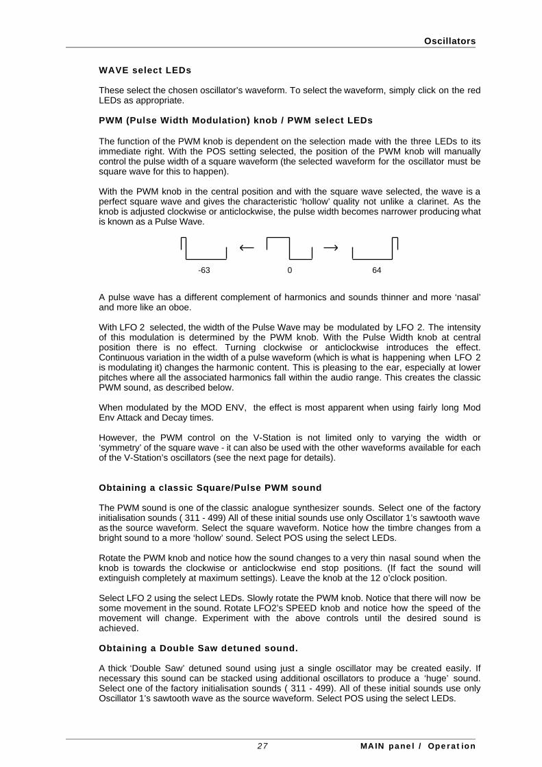
The function of the PWM knob is dependent on the selection made with the three LEDs to itsimmediate right. With the POS setting selected, the position of the PWM knob will manuallycontrol the pulse width of a square waveform (the selected waveform for the oscillator must besquare wave for this to happen).
With the PWM knob in the central position and with the square wave selected, the wave is aperfect square wave and gives the characteristic ‘hollow’ quality not unlike a clarinet. As theknob is adjusted clockwise or anticlockwise, the pulse width becomes narrower producing whatis known as a Pulse Wave.
-63 0 64
A pulse wave has a different complement of harmonics and sounds thinner and more ‘nasal’and more like an oboe.
With LFO 2 selected, the width of the Pulse Wave may be modulated by LFO 2. The intensityof this modulation is determined by the PWM knob. With the Pulse Width knob at centralposition there is no effect. Turning clockwise or anticlockwise introduces the effect.Continuous variation in the width of a pulse waveform (which is what is happening when LFO 2is modulating it) changes the harmonic content. This is pleasing to the ear, especially at lowerpitches where all the associated harmonics fall within the audio range. This creates the classicPWM sound, as described below.
When modulated by the MOD ENV, the effect is most apparent when using fairly long ModEnv Attack and Decay times.
However, the PWM control on the V-Station is not limited only to varying the width or‘symmetry’ of the square wave - it can also be used with the other waveforms available for eachof the V-Station’s oscillators (see the next page for details).
Obtaining a classic Square/Pulse PWM sound
The PWM sound is one of the classic analogue synthesizer sounds. Select one of the factoryinitialisation sounds ( 311 - 499) All of these initial sounds use only Oscillator 1’s sawtooth waveas the source waveform. Select the square waveform. Notice how the timbre changes from abright sound to a more ‘hollow’ sound. Select POS using the select LEDs.
Rotate the PWM knob and notice how the sound changes to a very thin nasal sound when theknob is towards the clockwise or anticlockwise end stop positions. (If fact the sound willextinguish completely at maximum settings). Leave the knob at the 12 o’clock position.
Select LFO 2 using the select LEDs. Slowly rotate the PWM knob. Notice that there will now besome movement in the sound. Rotate LFO2’s SPEED knob and notice how the speed of themovement will change. Experiment with the above controls until the desired sound isachieved.
Obtaining a Double Saw detuned sound.
A thick ‘Double Saw’ detuned sound using just a single oscillator may be created easily. Ifnecessary this sound can be stacked using additional oscillators to produce a ‘huge’ sound.Select one of the factory initialisation sounds ( 311 - 499). All of these initial sounds use onlyOscillator 1’s sawtooth wave as the source waveform. Select POS using the select LEDs.
27 MAIN panel / Operation

Oscillators
Rotate the PWM knob fully clockwise. As the control is rotated, a double sawtooth wave isgenerated. At this fully clockwise position the pitch will appear to double.
Select LFO 2 using the PW M select LEDs. Slowly rotate the PWM knob. Notice that there willbe some movement in the sound. Select a sawtooth LFO wave for LFO2 and rotate LFO2’sSPEED knob - notice how the speed of the movement will change. Experiment with the abovecontrols until the desired sound is achieved.
MOD ENV Knob
Controls the amount of pitch modulation to an oscillator from the Mod Envelope. In the centreposition there is no effect on the oscillator's pitch; anticlockwise the effect is negative (i.e. thepitch drops and then rises) and clockwise positive (the pitch rises and then falls).
LFO 1 Knob
Controls the amount of pitch modulation to an oscillator from LFO 1. It controls how muchabove and below the basic pitch the oscillator regularly rises and falls. If the LFO is set totriangle wave and the LFO’s speed knob is above the centre of its range, this will produce avibrato effect. Other effects like a siren or sea gull cry are possible with more extreme settings.
Some additional oscillator parameters can be found on the EXTRA page. These are describedon Pages 56 - 66.
28 MAIN panel / Operation

Mixer
MixerThe V-Station’s mixer makes it possible to combine the outputs of Oscillators 1, 2 and 3, theNoise source and the Ring modulator.
The ability to mix together any (or all) of these sound sources makes it easy to create complextimbres.
OSC 1, OSC 2 & OSC 3 Knobs
Controls the volumes of the three oscillators. Fully anticlockwise results in no signal. In thisposition and with all the other Mixer levels turned down, there will be no audio output. Fullyclockwise results in full volume for this oscillator.
NOISE
Controls volume of the White Noise Generator. White Noise is useful for creating sound effectssuch as wind and many other unpitched sounds.
RING 1+2
Controls the volume of the Ring Modulator. As we saw in the Synthesis Tutorial, the ringmodulator takes the outputs of Oscillators 1 and 2 and produces enharmonic overtones andfrequencies. As such ring modulation is useful for creating harder metallic tones.
SOLO buttons
Alongside each knob is a LED that can be clicked on to solo the associated sound source. Thiscan be useful when setting up a sound as it allows you to isolate the sound sources so that youcan concentrate solely on that element of the overall sound. When a source is solo’d, thebutton flashes.
29 MAIN panel / Operation

Filter
FilterThe V-Station’s filter is what is known as a ‘Low Pass’ type. This type of filter is musically themost useful for the majority of sounds.
FREQ Knob
This controls the basic cutoff frequency of the filter. Set fully clockwise, the filter is wide openallowing all frequencies (harmonics) produced by the oscillators to pass through.
Cutoff frequency
As the knob is turned anticlockwise, the filter closes, cutting out harmonics, starting with thehighest, then increasingly lower ones until only the fundamental (or nothing at all is allowed tosound - fully anticlockwise).
Cutoff frequency
Note : If there is silence when the VOLUME knob is turned up, it is most likely that the filter isfully closed. Turn the FREQ knob clockwise to open the filter.
RES Knob
This knob controls the resonance of the filter. The control will boost frequencies at the cutofffrequency. On some synthesizers, this control is known as Emphasis since it will emphasisecertain frequencies. At the zero position (i.e. fully counter-clockwise) there is no effect.Turning clockwise slowly introduces the emphasis.
Set fully clockwise, the filter will begin to self - oscillate, producing a new pitched element(similar to feedback on an electric guitar).
Note : At least a small signal must be fed into the filter in order for the resonance to take effect.It is not possible for the filter to self - oscillate if no signal at all is fed into it.
If the V-Station produces a high pitched whistling sound, it is probably due to this knob is beingadjusted too far clockwise. If this self-oscillating effect is not desired, keep the resonancecontrol away from the extreme clockwise setting. Increasing the resonance is very good forbringing out modulation (movement or change) in the filter cutoff frequency, such as in Acidbass lines and other very edgy sounds.
Q NORM Knob
Controls the Resonance Normalise. At zero, when resonance is applied, the main audio signalwill remain at normal levels. Adjusting clockwise will reduce the signal level in relation to theresonance level.
This feature enables the filter to emulate many of the classic filters such as the Moog type,Oberheim type and Roland TB303* type.
30 MAIN panel / Operation

Filter
O-DRIVE Knob
Controls how much the filter is overdriven. When used in large amounts it will have the effect ofmaking the sound richer and slightly distorted.
MOD ENV Knob
Controls the amount of change to the filter cutoff (set by the FREQUENCY knob) by theModulation Envelope.
In its central position there is no change to the filter cutoff frequency.
Adjusting the knob clockwise from centre will introduce an increasing amount of positivemodulation - the cutoff will rise through the MOD ENV’s attack and will fall through the MODENV’s subsequent decay and release stages.
Adjusting the knob anticlockwise from centre will introduce an increasing amount of negativemodulation and the MOD ENV effect will appear to be ‘upside down’ (i.e. the attack stage ofthe MOD ENV will force the cutoff frequency down and the decay’release stage will cause thecutoff to rise or ‘open’’)
SLOPE LEDs
Controls how drastically the frequencies above the cutoff point are removed from the sound.
When the 12dB position is selected, the cutoff slope is gentle so higher harmonics are notattenuated (reduced in volume) as sharply as they are when the 24dB position is selected.
12dB/Octave 24dB/Octave
Cutoff frequencyCutoff frequency
KEYTRACK Knob
Controls the amount of change to the filter cutoff (set by the FREQUENCY knob) by the pitchof the note played. Set fully anticlockwise, there is no change to the filter cutoff frequency aspitch increases. With clockwise movement there will be an increasing amount of modulationand the filter will be opened more as higher notes are played on the keyboard. This control isused to define how the timbre of a sound changes over the keyboard.
At the fully clockwise position, the filter tracks the pitch changes in a 1 to 1 ratio. This meansthat with RESONANCE set to a high level, the pitch of the filter’s self - oscillation will increase insemitone steps as notes are played on the keyboard. This effect is akin to adding an extra(Sine Wave) oscillator to the sound when notes are played on the keyboard.
LFO2 Knob
Controls the amount of change to the filter cutoff (set by the FREQUENCY knob) by LFO 2. Inits central position there is no change to the filter cutoff frequency.
Adjusting the knob clockwise from centre will introduce an increasing amount of positivemodulation - i.e. the filter will open and close at a rate set by LFO2’s SPEED control.
Adjusting the knob anticlockwise from centre will introduce an increasing amount of negativemodulation - i.e. the filter will close and open at a rate set by LFO2’s SPEED control.
31 MAIN panel / Operation

Envelopes
Amplifier and Mod envelopesThe V-Station’s envelopes are used to shape a sound throughout its duration. The AMPENVdetermines the volume of the sound with respect to its duration.
The MOD ENV may be used to control other sound elements of the synthesizer throughoutthe duration of the sound. It can control oscillator pulse width, filter frequency and oscillatorpitch.
Using the controls associated with the two envelopes, you can ‘shape’ the sound:
Note on Note off
Level
Attack Decay Sustain Release
ATTACK Knob / Slider
Sets how quickly the envelope rises to its maximum level when a note is struck. Fullyanticlockwise and this rise time or slope is very fast increasing exponentially to twenty secondswhen fully clockwise. To shorten attack times, turn this control towards zero and to lengthenattack times, turn this control towards maximum.
Note : When the attack time is set to zero, the instantaneous rise time of the Envelope mayproduce audible ‘clicks’. This is not a faulty condition and may be useful for the creation ofcertain sounds (for example, ‘key clicks’ on organ simulations). If this is undesirable, increasethe Attack time until the clicks are inaudible.
DECAY Knob / Slider
Sets how quickly the envelope falls to a sustain level after the maximum level has beenreached. Set to zero, this time is very fast increasing exponentially to twenty seconds when setto maximum. To shorten decay times, move this control towards zero and to lengthen decaytimes move this control towards maximum.
SUSTAIN Knob / Slider
Sets the level at which the envelope remains following the Decay phase, only while a key isbeing held on a controller keyboard (or there is a MIDI Note On command present). When set tozero, the envelope will decay to zero without being interrupted. As the control is movedtowards maximum, the sustain level increases until, when at maximum, the sustain level is at itsmaximum level.
Note: When SUSTAIN level is set to maximum, the DECAY control has no effect - with sustainat full, there’s nothing to decay down too!
32 MAIN panel / Operation

Envelopes
RELEASE Knob / Slider
Sets how quickly the envelope falls from the sustain level to zero once the note has beenreleased. When set to zero, this time is very fast (instantaneous to the ear) increasingexponentially to twenty seconds when set to maximum. To shorten release times, move thiscontrol towards zero and to lengthen release times, move this control towards maximum.
Additional settings associated with the Envelopes can be found on the EXTRA page. Theseare described on Pages 56 - 66.
33 MAIN panel / Operation

LFOs
Low Frequency Oscillators (LFOs)There are two LFOs - Low Frequency Oscillators - available on the V-Station. These produceregular electronic variations which are too low to be heard but can be used to modify or controlvarious elements of the sound such as pitch (vibrato), pulse width or filter cutoff.
SPEED Knob
Controls the speed of the low frequency oscillations. An LED directly above the knob indicatesthe speed. Faster speeds are set by turning the knob clockwise. These are suitable for vibratoand tremolo effects. Slower speeds are more appropriate for Pulse Width changes, slow filtersweeps or special effects.
DELAY Knob
Controls how long after the note is struck the selected LFO begins to take effect. Fullyanticlockwise and the selected LFO effect will begin immediately. Turning clockwise will causethe LFO effect to fade in. The time of the fade in is dependent on the knob position. This isused for delayed vibrato and other effects.
WAVE LEDs
Selects the waveform shape.
The triangle waveform gives the smoothest continuous change in level to theLFO. When routed to pitch, it introduces vibrato or a siren effect dependent ofits speed setting. When routed to filter cutoff, a ‘wow wow’ effect results.
The sawtooth waveform generates a rising level which then jumps back up tozero level. Routed to the filter cutoff, it produces a rhythmic pulse effect.Routing it to pitch produces siren type sounds.
The square waveform changes level instantly from minimum to maximum. Thiswaveform is useful for musical trills and computer game effects.
S/H Sample & Hold. At a regular interval (governed by the SPEED knob), the levelof the LFO jumps to a new random level and stays there until the next jump.This creates a rhythmic effect particularly if routed to the filter cutoff. Routingthis to pitch gives a less musical result, but is useful for computer or machinerysound effects.
Additional settings associated with the LFOs can be found on the EXTRA page. These aredescribed on Pages 56 - 66.
34 MAIN panel / Operation

Master Section
Master sectionAlthough unlabelled as such, this section houses certain ‘master’ controls that affect theV-Station
PROGRAM up/down buttons
Use these to select programs in the V-Station. You can click on them individually to go throughthe sounds one-by-one but if you click and hold these buttons, the program selection willincrement / decrement in units of 10 to make program selection quicker and easier.
VOLUME Knob
This control adjusts the overall output volume on the main master audio outputs. This controlcan be useful for preventing distortion on your sequencer’s mixer.
LCD
This ‘virtual’ LCD allows you to see program numbers and names. However, when you movethe cursor over any knobs and switches, after a short delay, the parameter name and its value isshown on the LCD:
COMPARE button
Clicking and holding this button when editing a sound allows you to compare the original withyour edited version.
WRITE button
Allows you to write any sounds you edit or create to the V-Station’s memory. Clicking on this willput a prompt in the LCD:
If you want to over-write the existing sound, simply click on CONFIRM - the sound will be writtento the current location.
Note : The destination memory is always initially set to the currently selected program’snumber.
35 MAIN panel / Operation

Master Section
If you want to save the sound in a different location (thereby retaining the original sound in itsoriginal location), using the PROGRAM up/down buttons, select the destination memory andclick on CONFIRM.
To cancel the WRITE operation, simply click on WRITE again.
Notes about editing programs
When you select a sound, you can start editing it immediately simply by tweaking the controlsand no special ‘edit’ mode is required. However, please note that if you do edit a sound, shouldyou then select another, by default, the edits you made to the previous sound will be lost.However, it is possible to overcome this: In the GLOBAL page, there is a preference - AUTOWRITE - which, when enabled, will automatically write programs to memory if another program isselected. By default, this is off.
With AUTO-WRITE enabled, selecting another sound will automatically write your editedversion before the next sound is selected.
CONFIRM button
As described above, the CONFIRM button is used to confirm the act of writing a program tomemory.
VOICE METER
Below the Master section is a voice meter that shows how many voices are being used. TheV-Station is capable of 8-voice polyphony.
MIDI indicator LED
This flashes whenever a MIDI note is received. If this LED does not flash wien a note is played,there is a problem with MIDI reception.
36 MAIN panel / Operation

Arpeggiator
ArpeggiatorThe V-Station includes an Arpeggiator which breaks down chords into single notes and playsthem one at a time. For example, if a ‘C’ triad chord is held, the notes C, E and G will play one byone in sequence. This section of the MAIN panel allows you to select the arpeggiator’s patternand range.
PATTERN menu
This determines the Arpeggio pattern played by the Arpeggiator. There are six types of patternavailable :
UP The arpeggio starts at the lowest note played and sweeps up throughthe notes until it reaches the highest note. It then starts at the bottomagain and repeats the sequence.
DOWN The arpeggio starts at the highest note played and sweeps downthrough the notes until it reaches the lowest note. It then starts at thetop again and repeats the sequence.
UD1 Up / Down : The arpeggio starts at the lowest note played and sweepsup through the notes until it reaches the highest note. It then sweepsback down. This is useful when playing three notes in songs with a 3/4time signature.
UD2 Up/Down - end repeat: The arpeggio starts at the lowest note played,plays it twice, and sweeps up through the notes until it reaches thehighest note. It then plays the top note again and sweeps back down.
ORD Order Played: The arpeggio plays the notes in the order they wereplayed on the keyboard. Once at the end of the notes played itrepeats the sequence.
RND Random: Notes played will be arpeggiated in a random order.
37 MAIN panel / Operation

Arpeggiator
RANGE menu
Sets how many octaves the Arpeggio pattern will sweep through. The sweep range isselectable from 1 to 4 octaves.
ON / OFF Button
This activates / deactivates the Arpeggiator. While the Arpeggiator is activated, the LED in thebutton will be lit.
There are other parameters related to the arpeggiator on the EXTRA page. These aredescribed on Pages 56-66.
38 MAIN panel / Operation

Portamento
PortamentoPortamento (sometimes known as GLIDE) is an effect where notes will slide smoothly from onepitch to the next.
Normally, when you play, notes just ‘play’ - they change pitch instantly as you would expect.However, with portamento applied, the notes will slide from one to another at a rate determinedby the portamento TIME control. This can be useful for simulating certain instruments such asfretless bass, trombone, etc., but is also a rich source of synth sounds and effects not least ofwhich, of course, is an emulation of the famous Theremin.
Increasing the portamento TIME control clockwise will slow the time taken for the pitch of thefirst note to reach that of the second note played. With this control set to zero, when thekeyboard is played, the pitches of notes change instantly from one pitch to another. Turningthe knob clockwise introduces the portamento effect.
The ON / OFF switch allows you to enable / disable the effect.
Other PORTAMENTO functions are available in the EXTRA page. See Pages 56 - 66 for moredetails.
39 MAIN panel / Operation

Effects / Delay
Effects sectionAt the bottom right of the V-Station’s panel is a section where you can program the V-Station’seffects.
The V-Station has six effects - delay (echo), reverb, chorus (which can also produce flangingand phasing effects), distortion, EQ and panning - which can be used simultaneously. To editthe effects, simply click on the LEDs. As the different effects are selected, the controls to theright of the LEDs change to reflect the controls available for the currently selected effect type.One control, however, that is consistent to all six effects is the LEVEL control - this sets thelevel of the signal going to the selected effect - the higher the level, the more of the effect youwill hear.
Another parameter that is consistent between all six effects is the ON/OFF switch - this is usedto disable all six effects in one convenient action. If you want to remove one effect from thechain, set its LEVEL control to zero (i.e. fully counter-clockwise).
Note: The effects use a fair chunk of CPU processing power. If you find performance is beingaffected, disabling the V-Station’s effects with the ON/OFF button can significantly reduce thestrain.
DelayThe first effect in the list is DELAY. The delay effects parameters are:
TIME Knob
Controls the amount of time it takes for the delayed signal to be heard after the original signal.
FEEDBACK Knob
Controls how much of the delayed signal is fed back into the delay input. No feedbackproduces a slapback echo effect - just one delayed sound with no repeats. Small amounts offeedback produce repeated sounds resulting in a multiple echo effect. Large amounts offeedback can produce infinite echoes.
WIDTH Knob
This sets the Stereo spread between the long and short Delay times. With a width setting ofzero, both delays appear in the middle of the stereo field (Mono). At maximum width setting,the longer delay will appear on one output and the shorter on the other, producing a dramaticstereo effect.
40 MAIN panel / Operation

Delay
RATIO Menu
The V-Station’s delay effect is actually a stereo delay and it is possible to set different delaytimes on the left and right audio outputs. The RATIO menu allows you to select the ratio of thelongest delay time and the shorter delay time into timings that are musically useful. Thefollowing ratios are available:
1/14/33/43/22/32/11/23/11/34/11/4
1/OFFOFF/1
Left / RightDelay Ratios
A simple, equal 1 to 1 ratio is the first entry in the table. This setting sends a delay of equal timeto the left and right output channels. The number in the left column of the table indicates theratio of the delay time that will be in the left channel versus the number in the right column.
For example, if a delay of twice the time is required in the left channel compared to the right,select the 2/1 option. The final 1/OFF and OFF/1 options will result in no delay being heard inthe channel indicated by the ‘OFF’.
Note: Selecting a 1/1 ratio will produce a mono effect regardless of the stereo WIDTH settingsince the timing of the echos are equal.
41 MAIN panel / Operation

Delay
SYNC RATE Menu
Enables the time of the Delay repeats to be synchronised to the tempo of a song. Thefollowing table gives the range of synchronisation values available.
OFF32nd T32nd16th T16th8th T16th D8th4th T8th D4th2nd T4th D2nd1bar T2nd D1bar2bar T1bar D2bars
-23468912161824323648647296
128144192
Manual rate32nd Triplet32nd16th Triplet16th8th Triplet16th Dotted8th4th Triplet8th Dotted4th2nd Triplet4th Dotted2nd1 Bar Triplet2nd Dotted1 Bar2 Bars Triplet1.5 Bars2 bars
Menu Item MIDI Clocks Synchronised to
When a sync interval is selected, the delay time is controlled by the sequencer’s tempo whenMIDI clock source is set to EXT (the default). If the MIDI clock source is set to INT, theArpeggiator’s TEMPO knob controls the delay time.
Note : When Sync Rate is set to OFF, the timing of the delay repeats will be controlled by thesetting of the delay effect’s Time control. Any incoming MIDI clock messages or ArpeggiatorTEMPO settings will be ignored .
42 MAIN panel / Operation

Reverb
ReverbThe Reverb Effect is an electronic simulation of a room or building that is acoustically reflective.
When a sound is made in a room or large building, there are sound reflections from alldirections. Unlike echo where you hear each reflection individually, the reflections in areverberant space ‘smudge’ together to create the reverb sound we are familiar with. When areverb effect is applied, it is these ‘smudged’ reflections of the sound that are being added.
LEVEL Knob
Sets the amount of signal going to the reverb. As the control is turned clockwise, so you willhear more reverb.
DECAY Knob
This sets the time it takes for the Reverb to die away after the original sound has decayed. Veryacoustically reflective rooms (like those with metal or glass surfaces) tend to have long decaytimes and non-reflective rooms have short ones.
TYPE Menu
Different types of rooms and halls have different acoustics and, therefore, different reverbcharacteristics. The V-Station’s reverb processor features six different reverb types. Theserange from a small room to a large hall:
Experiment with different types of reverb, noting how different ‘rooms’ affect the acousticproperties of the sound.
43 MAIN panel / Operation

Chorus / Flange / Phaser
ChorusThis effect was originally designed to simulate the sound of many people singing together(hence the name ‘chorus’) . Instrumentally, consider the sound of a 12 string guitar comparedto a 6 string guitar. The very slight detuning of the individual strings actually gives a richerquality to the sound.
Chorus is an effect produced by mixing a continuously delayed version of the audio signal backwith the original. The timing of the delayed version is very small and is controlled by thechorus’s own internal LFO (not to be confused with the two LFOs available on the V-Station’sMAIN panel). The characteristic swirling chorus effect is the result.
The V-Station’s chorus is a stereo unit which adds width as well as depth to the sound.
The V-Station’s chorus is also capable of behaving as a phaser. The way a phaser works is infact entirely different to the chorus. A portion of the audio signal is split off and phase shifted atcertain frequencies. It is then mixed back with the original signal to generate the characteristicswishing effect. The controls are:
LEVEL Knob
Sets the amount of signal going to the chorus. As the control is turned clockwise, so you willhear more chorus.
CHORUS / PHASER LEDs
Determines whether the V-Station’s chorus behaves as a standard chorus or as a phaser.
RATE Knob
Controls the rate or speed of the chorus effect. At very slow speeds (and with DEPTH andFEEDBACK set fairly high) , the chorus can also be used as a flanger.
Note : The dedicated chorus LFO should not be confused with the two LFOs available on theV-Station’s MAIN panel.
FEEDBACK Knob
Controls how much of the delayed signal is fed back to the input of the chorus generator. Thechorus effect benefits from low levels of feedback. When acting as a flanger or a phaser , theeffect often requires higher levels of feedback.
44 MAIN panel / Operation
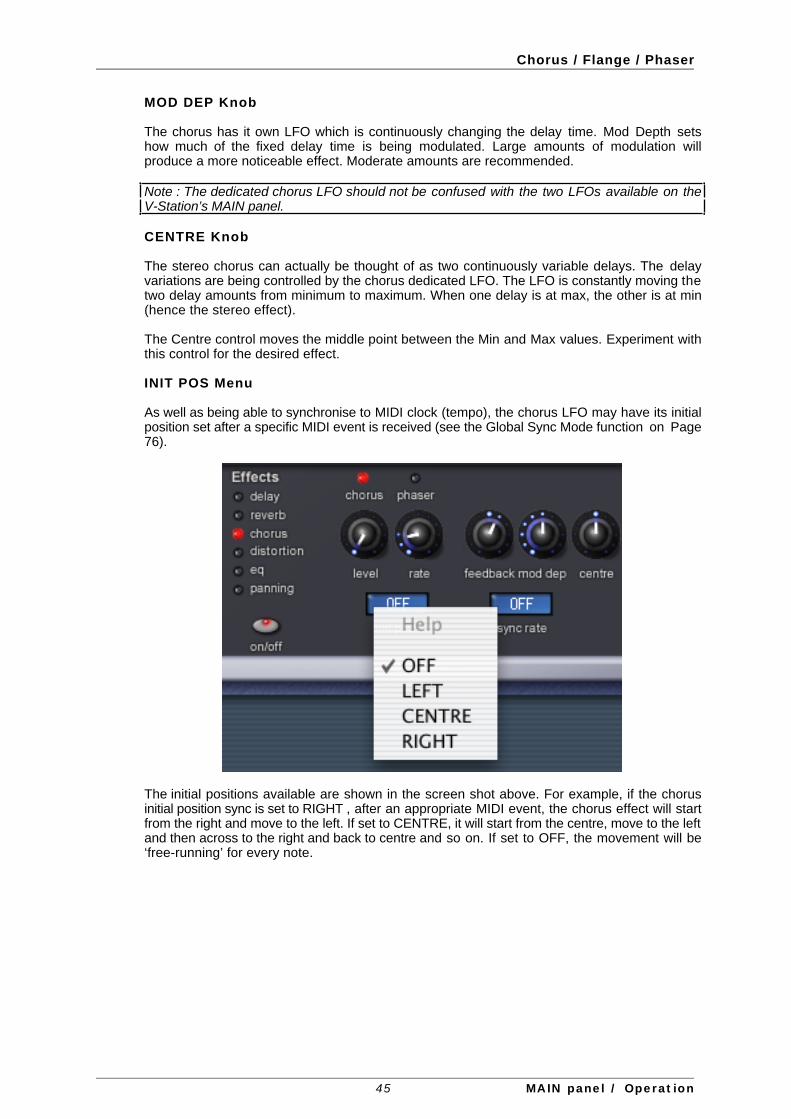
Chorus / Flange / Phaser
MOD DEP Knob
The chorus has it own LFO which is continuously changing the delay time. Mod Depth setshow much of the fixed delay time is being modulated. Large amounts of modulation willproduce a more noticeable effect. Moderate amounts are recommended.
Note : The dedicated chorus LFO should not be confused with the two LFOs available on theV-Station’s MAIN panel.
CENTRE Knob
The stereo chorus can actually be thought of as two continuously variable delays. The delayvariations are being controlled by the chorus dedicated LFO. The LFO is constantly moving thetwo delay amounts from minimum to maximum. When one delay is at max, the other is at min(hence the stereo effect).
The Centre control moves the middle point between the Min and Max values. Experiment withthis control for the desired effect.
INIT POS Menu
As well as being able to synchronise to MIDI clock (tempo), the chorus LFO may have its initialposition set after a specific MIDI event is received (see the Global Sync Mode function on Page76).
The initial positions available are shown in the screen shot above. For example, if the chorusinitial position sync is set to RIGHT , after an appropriate MIDI event, the chorus effect will startfrom the right and move to the left. If set to CENTRE, it will start from the centre, move to the leftand then across to the right and back to centre and so on. If set to OFF, the movement will be‘free-running’ for every note.
45 MAIN panel / Operation
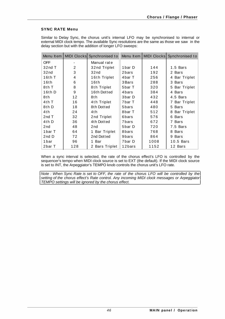
Chorus / Flange / Phaser
SYNC RATE Menu
Similar to Delay Sync, the chorus unit’s internal LFO may be synchronised to internal orexternal MIDI clock tempo. The available Sync resolutions are the same as those we saw in thedelay section but with the addition of longer LFO sweeps:
OFF32nd T32nd16th T16th8th T16th D8th4th T8th D4th2nd T4th D2nd1bar T2nd D1bar2bar T
-23468912161824323648647296
128
Manual rate32nd Triplet32nd16th Triplet16th8th Triplet16th Dotted8th4th Triplet8th Dotted4th2nd Triplet4th Dotted2nd1 Bar Triplet2nd Dotted1 Bar2 Bars Triplet
Menu Item MIDI Clocks Synchronised to
1bar D2bars4bar T3Bars5bar T4bars3bar D7bar T5bars8bar T6bars7bars5bar D8bars9bars7bar D12bars
144192256288320384432448480512576672720768864
10081152
1.5 Bars2 Bars4 Bar Triplet3 Bars5 Bar Triplet4 Bars4.5 Bars7 Bar Triplet5 Bars8 Bar Triplet6 Bars7 Bars7.5 Bars8 Bars9 Bars10.5 Bars12 Bars
Menu Item MIDI Clocks Synchronised to
When a sync interval is selected, the rate of the chorus effect’s LFO is controlled by thesequencer’s tempo when MIDI clock source is set to EXT (the default). If the MIDI clock sourceis set to INT, the Arpeggiator’s TEMPO knob controls the chorus unit’s LFO rate.
Note : When Sync Rate is set to OFF, the rate of the chorus LFO will be controlled by thesetting of the chorus effect’s Rate control. Any incoming MIDI clock messages or ArpeggiatorTEMPO settings will be ignored by the chorus effect.
46 MAIN panel / Operation

Distortion
DistortionDistortion is an effect commonly used by guitar players. However, it is now increasingly used inthe production of modern dance music. The V-Station’s distortion effect gives the sound ahard edged, distorted and dirty kind of quality.
LEVEL Knob
Sets the amount of signal going to the distortion. As the control is turned clockwise, so you willhear more distortion.
COMP Knob
If distortion is added to a sound, it will tend to get louder. In order to reduce the level of thesound back to a level which is consistent with other programs, use this function whichcompensates for the perceived added loudness of a sound when distortion is added.
47 MAIN panel / Operation

EQ
EQ (Equalisation)Contained in the Effects section is an EQ filter which can boost or cut high (treble) or low (bass)frequencies in a similar manner to the ‘tone’ controls often found on domestic hi-fi units.
As well as being able to boost low or high frequencies, the final output EQ filter may be used tocreate automatic sweeps of EQ and filtering. EQ processing may be synchronised to tempoand locked to musical timings from 32nd triplets through to several bars.
LEVEL Knob
The LEVEL control has a different purpose with the EQ effect in that instead of setting thesend level to the effect, it actually sets the amount of cut / boost around the centre frequency.
FREQUENCY Knob
The EQ frequency control determines where in the sound spectrum the boost or cut occurs.The Frequency point may be moved anywhere from very low frequencies (0 = less than 10Hz)to very high frequencies (127 = above 20,000Hz).
EQ Frequency (5)
10Hz 500Hz 1kHz 5kHz 20kHz
Boost
Cut
0dB
EQ Level : -64
Here, FREQ is set to 0 (i.e. around 10Hz) and LEVEL is set to -64 (cut). As a result, all the highfrequency component has been removed.
48 MAIN panel / Operation

EQ
EQ Frequency (64)
10Hz 500Hz 1kHz 5kHz 20kHz
Boost
Cut
0dB
EQ Level : 63
Here, the FREQ control is set halfway (64) and LEVEL is set to -64. The result is extreme bassboost (ideal for reinforcing bass sounds).
EQ Frequency (64)
10Hz 500Hz 1kHz 5kHz 20kHz
Boost
Cut
0dB
EQ Level : 63
Here, the FREQ is set halfway (64) but level is set to +64. The result is that high frequencycomponents are boosted and low frequency components are attenuated
MOD DEP Knob
The real power of the EQ filter is the ability to move the EQ Frequency with the dedicated LFO.This control (MOD DEP or ‘modulation depth’)dictates how intense the movements are fromthe LFO. Any amount of depth will result in dynamic EQ frequency movement at a ratedetermined by the EQ MOD RATE control. The effect is not unlike that of a mild filter sweepand can be used creatively to augment the V-Station’s filter section.
Note : The dedicated EQ LFO should not be confused with the two LFOs available on theV-Station’s MAIN panel.
49 MAIN panel / Operation
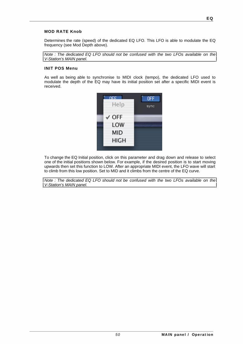
EQ
MOD RATE Knob
Determines the rate (speed) of the dedicated EQ LFO. This LFO is able to modulate the EQfrequency (see Mod Depth above).
Note : The dedicated EQ LFO should not be confused with the two LFOs available on theV-Station’s MAIN panel.
INIT POS Menu
As well as being able to synchronise to MIDI clock (tempo), the dedicated LFO used tomodulate the depth of the EQ may have its initial position set after a specific MIDI event isreceived.
To change the EQ Initial position, click on this parameter and drag down and release to selectone of the initial positions shown below. For example, if the desired position is to start movingupwards then set this function to LOW. After an appropriate MIDI event, the LFO wave will startto climb from this low position. Set to MID and it climbs from the centre of the EQ curve.
Note : The dedicated EQ LFO should not be confused with the two LFOs available on theV-Station’s MAIN panel.
50 MAIN panel / Operation
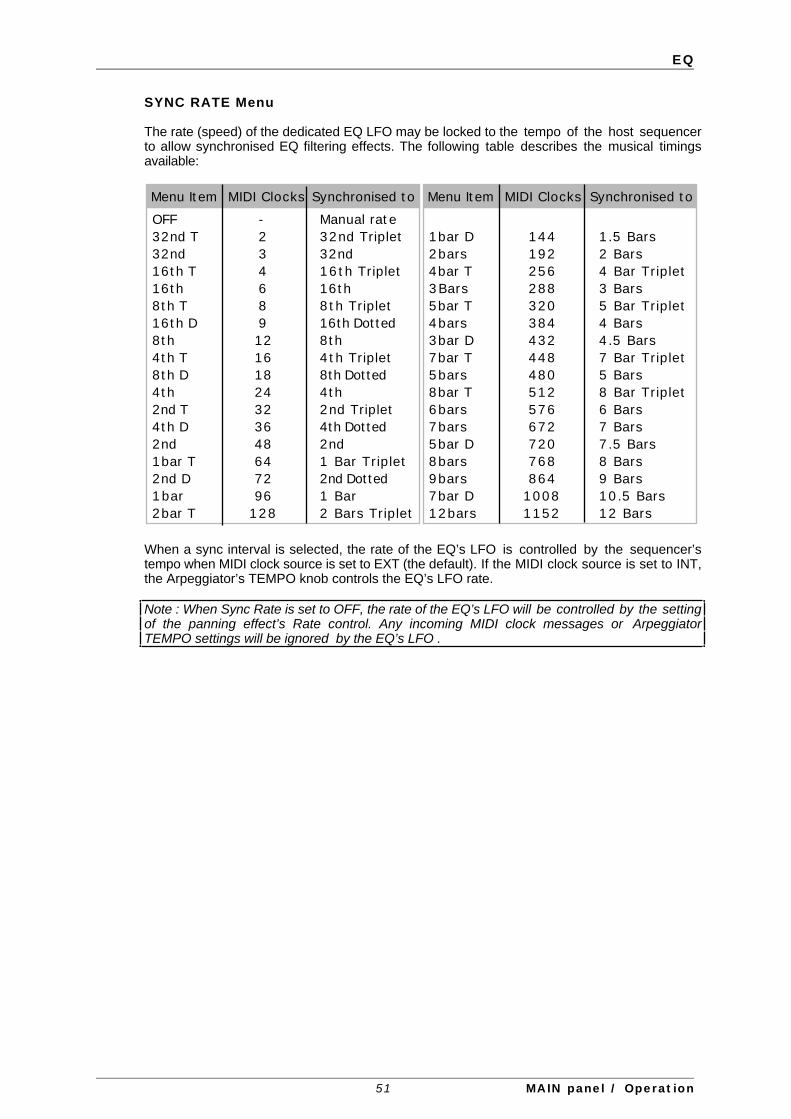
EQ
SYNC RATE Menu
The rate (speed) of the dedicated EQ LFO may be locked to the tempo of the host sequencerto allow synchronised EQ filtering effects. The following table describes the musical timingsavailable:
OFF32nd T32nd16th T16th8th T16th D8th4th T8th D4th2nd T4th D2nd1bar T2nd D1bar2bar T
-23468912161824323648647296
128
Manual rate32nd Triplet32nd16th Triplet16th8th Triplet16th Dotted8th4th Triplet8th Dotted4th2nd Triplet4th Dotted2nd1 Bar Triplet2nd Dotted1 Bar2 Bars Triplet
Menu Item MIDI Clocks Synchronised to
1bar D2bars4bar T3Bars5bar T4bars3bar D7bar T5bars8bar T6bars7bars5bar D8bars9bars7bar D12bars
144192256288320384432448480512576672720768864
10081152
1.5 Bars2 Bars4 Bar Triplet3 Bars5 Bar Triplet4 Bars4.5 Bars7 Bar Triplet5 Bars8 Bar Triplet6 Bars7 Bars7.5 Bars8 Bars9 Bars10.5 Bars12 Bars
Menu Item MIDI Clocks Synchronised to
When a sync interval is selected, the rate of the EQ’s LFO is controlled by the sequencer’stempo when MIDI clock source is set to EXT (the default). If the MIDI clock source is set to INT,the Arpeggiator’s TEMPO knob controls the EQ’s LFO rate.
Note : When Sync Rate is set to OFF, the rate of the EQ’s LFO will be controlled by the settingof the panning effect’s Rate control. Any incoming MIDI clock messages or ArpeggiatorTEMPO settings will be ignored by the EQ’s LFO .
51 MAIN panel / Operation

Panning
PanningThe Panning function in the V-Station performs the same function as the PAN knob on amixing console. It can be used to position a sound anywhere from left to right in the stereofield.
POS Knob
Uniquely, the PANNING effect does not have a LEVEL control. Instead, it has a POS (anabbreviation for ‘position’) control to place the sound in the left / right output.
MOD RATE Knob
Controls the panning LFO’s speed. If the Mod Depth (see below) is set to a non zero value, thepanning LFO will move the sound from the Left to the Right at a speed determined by this Ratesetting
Note : The panning LFO should not be confused with the two LFOs available on theV-Station’s MAIN panel.
MOD DEP Knob
The panning effect has its own dedicated LFO (not to be confused with the two LFOs availableon the V-Station’s MAIN panel) which can be used to automatically pan a sound backwards andforwards across the stereo field. This control (an abbreviation of ‘modulation depth’) controlsthe depth of this automatic panning effect.
When Mod Depth is set to zero, no automatic panning will be applied and the position of asound in the stereo field will be static, being solely determined by the POS(ition) control.
52 MAIN panel / Operation

Panning
INIT POS Menu
As well as being able to be synchronised to a MIDI clock (tempo), the panning LFO may have itsinitial position set after a specific MIDI event is received.
The initial positions are shown in the screen shot above. For example, if the panning initialposition sync is set to RIGHT (Right), after an appropriate MIDI event has been received, thesound will begin in the right output audio channel and then move towards the left. If set toCENTRE, the panning will start at the centre, move to the left then back to the right and then tothe centre, etc.. If set to OFF, the panning will be ‘free-running’ for every note.
Note : The panning LFO should not be confused with the two LFOs available on theV-Station’s MAIN panel.
53 MAIN panel / Operation

Panning
SYNC RATE Menu
A very pleasing audio effect may be heard when the panning effect is synchronised to thetempo of a musical piece. The following table describes the musical timings available:
OFF32nd T32nd16th T16th8th T16th D8th4th T8th D4th2nd T4th D2nd1bar T2nd D1bar2bar T
-23468912161824323648647296
128
Manual rate32nd Triplet32nd16th Triplet16th8th Triplet16th Dotted8th4th Triplet8th Dotted4th2nd Triplet4th Dotted2nd1 Bar Triplet2nd Dotted1 Bar2 Bars Triplet
Menu Item MIDI Clocks Synchronised to
1bar D2bars4bar T3Bars5bar T4bars3bar D7bar T5bars8bar T6bars7bars5bar D8bars9bars7bar D12bars
144192256288320384432448480512576672720768864
10081152
1.5 Bars2 Bars4 Bar Triplet3 Bars5 Bar Triplet4 Bars4.5 Bars7 Bar Triplet5 Bars8 Bar Triplet6 Bars7 Bars7.5 Bars8 Bars9 Bars10.5 Bars12 Bars
Menu Item MIDI Clocks Synchronised to
When a sync interval is selected, the rate of the panning LFO is controlled by the sequencer’stempo when MIDI clock source is set to EXT (the default). If the MIDI clock source is set to INT,the Arpeggiator’s TEMPO knob controls the delay time.
When controlling the panning rate from a sequencer, it is important to ensure that thesequencer is transmitting MIDI Clock messages. Consult the sequencer manual for details.
Note : When Sync Rate is set to OFF, the rate of the panning LFO will be controlled by thesetting of the panning effect’s Rate control. Any incoming MIDI clock messages or ArpeggiatorTEMPO settings will be ignored .
54 MAIN panel / Operation

Conclusion
ConclusionThat concludes our examination of the MAIN panel. Armed with the knowledge you have(hopefully!) gained here and the Synthesis Tutorial, you should now be able to makemeaningful edits to any of the preset sounds on offer (or even create your own sounds fromscratch)
In the next section, we’ll look at some of the lesser-used (but no less important) functions ofthe V-Station.
55 MAIN panel / Operation

EXTRA panel
EXTRA panel
The EXTRA page is where you’ll find the little ‘extras’ that add a lot to the basic functionality butare only used occasionally and don’t warrant cluttering up the MAIN panel.
As on the MAIN panel, the sections are divided up logically. We will look at these in this chapter.
56 EXTRA panel / Operation
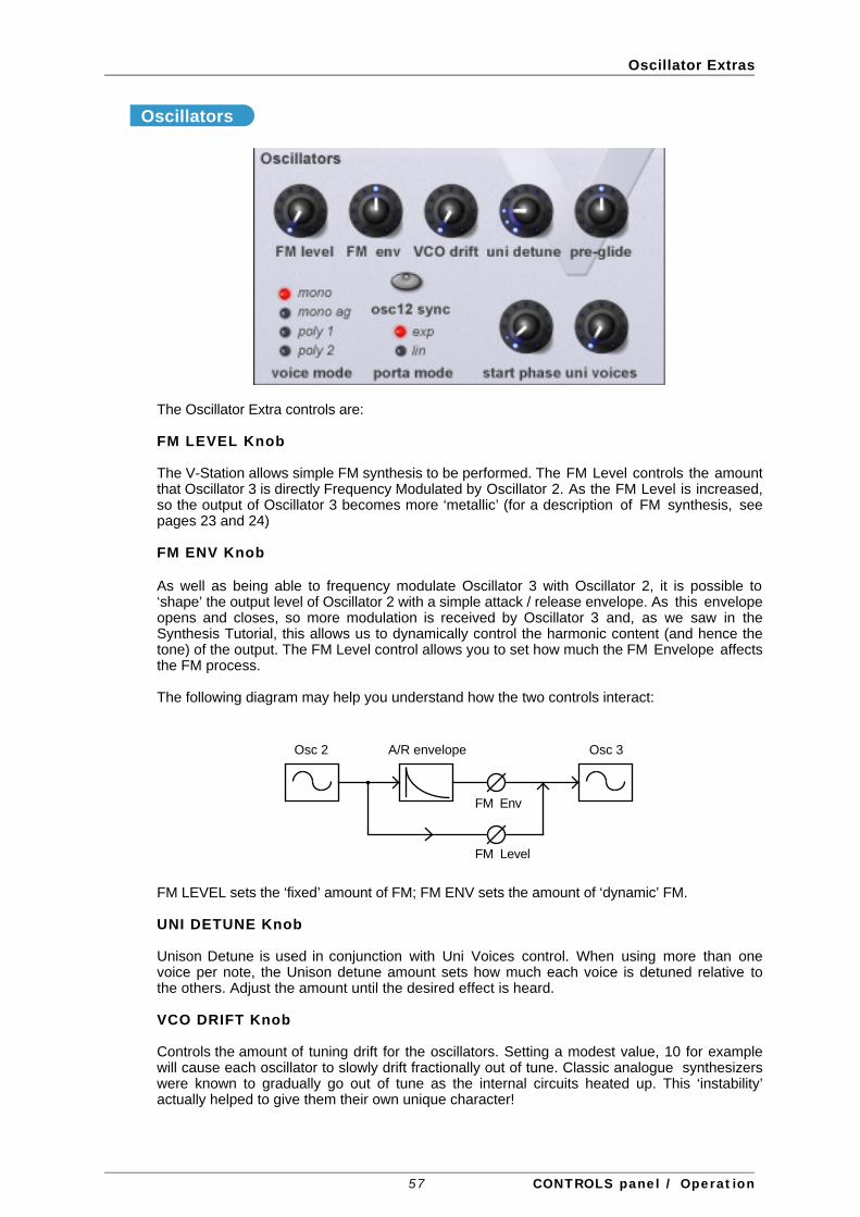
Oscillator Extras
Oscillators
The Oscillator Extra controls are:
FM LEVEL Knob
The V-Station allows simple FM synthesis to be performed. The FM Level controls the amountthat Oscillator 3 is directly Frequency Modulated by Oscillator 2. As the FM Level is increased,so the output of Oscillator 3 becomes more ‘metallic’ (for a description of FM synthesis, seepages 23 and 24)
FM ENV Knob
As well as being able to frequency modulate Oscillator 3 with Oscillator 2, it is possible to‘shape’ the output level of Oscillator 2 with a simple attack / release envelope. As this envelopeopens and closes, so more modulation is received by Oscillator 3 and, as we saw in theSynthesis Tutorial, this allows us to dynamically control the harmonic content (and hence thetone) of the output. The FM Level control allows you to set how much the FM Envelope affectsthe FM process.
The following diagram may help you understand how the two controls interact:
Osc 2 A/R envelope Osc 3
FM Env
FM Level
FM LEVEL sets the ‘fixed’ amount of FM; FM ENV sets the amount of ‘dynamic’ FM.
UNI DETUNE Knob
Unison Detune is used in conjunction with Uni Voices control. When using more than onevoice per note, the Unison detune amount sets how much each voice is detuned relative tothe others. Adjust the amount until the desired effect is heard.
VCO DRIFT Knob
Controls the amount of tuning drift for the oscillators. Setting a modest value, 10 for examplewill cause each oscillator to slowly drift fractionally out of tune. Classic analogue synthesizerswere known to gradually go out of tune as the internal circuits heated up. This ‘instability’actually helped to give them their own unique character!
57 CONTROLS panel / Operation

Oscillator Extras
PRE-GLIDE Knob
A Pre-glide is applied to the pitch of the oscillators starting at a pitch determined by the Pre-glide amount in semitones. Gliding up from a pitch occurs when the display indicates between-12 to -1, and gliding down from a pitch occurs when the display indicates between 1 to 12. At asetting of 0, no pre-glide is applied.
The time it takes to complete the Glide is determined by the PORTAMENTO knob on the MAINpanel. The Pre-glide is triggered with every note received.
VOICE MODE select LEDs
These options determine how the program will play - i.e. polyphonically or monophonically.
When set to MONO or MONO AG, the Program plays monophonically (i.e. only one note canbe sounded at any one time). If a chord is played on the keyboard, it will be noticed that as eachindividual note is released, the note sounding will revert back to the nearest played note.
The MONO AG setting enables ‘Auto glide’ (portamento) to be triggered whenever a note isplayed on the keyboard before the previously held down note has been released (legatoplaying). Using ‘Auto glide’ in this way can greatly add expressiveness to a Program. It isespecially effective when applied to lead type sounds.
The monophonic settings are often useful when replicating sounds in the ‘real world’ whichwould normally be played monophonically, for example a bass guitar.
As their name implies, the POLY 1 and POLY 2 settings allow polyphonic operation.
POLY1 allows successive playing of the same note(s) to be ‘stacked’ together, graduallyproducing a louder sound texture as the note(s) are repeatedly played.
With POLY2, if the same note(s) are played repeatedly, they will use the same synthesizervoices as used previously, thus avoiding the ‘stacked note’ effect.
PORTA MODE select LEDs
Determines the type of curve applied when PORTAMENTO is used. Two types of curve areavailable, Exponential and Linear. Linear Portamento sweeps through note intervals at aconstant rate. When Exponential Portamento is used, the glide effect gradually speeds up as itreaches the new note:
LinearExponential
OSC 1+2 SYNC Button
This button synchronises Oscillator 1 to Oscillator 2. When the oscillators are synced, Oscillator1 is the ‘master’ oscillator to which Oscillator synchronises. Depending on the interval betweenthe two oscillators, you can create new waveforms with oscillator sync enabled and if yousweep Oscillator 2 independently of Oscillator 2 with, say, the LFO or Mod Env or the pitchbend or mod wheel, you can create tearing lead lines and basses.
58 CONTROLS panel / Operation

Oscillator Extras
START PHASE Knob
When synthesising percussive or plucked type sounds, there is a lot of detailed waveforminformation at the beginning of the sound. It is often useful to have the oscillator wave start inexactly the same place every time a key is pressed.
The start phase option allows the precise starting point of the oscillator wave to be determined.At a setting of 0, the wave will start at zero degrees. Each increment on the control shifts thestart point of the wave approximately 24 degrees. The wave will start at a random phase whenset to OFF.
UNI VOICES Knob
Unison allows more than one voice to be used for each note played on the keyboard. Thiseffect is useful when a very thick sound is required. The V-Station allows up to eight voices tosound layered one on top of another when just a single note is played.
To listen to the effect, play a series of notes whilst gradually increasing this control and listen tothe sound. It will become thicker sounding. Increasing the number of notes to a maximum of 8will result in very dense sounding textures.
Note: As more voices are assigned to Unison, the available polyphony will reduce accordingly.For example, using 8 voices in Unison mode will result in just one note of polyphony beingavailable!
59 CONTROLS panel / Operation

Arpeggiator Extras
Arpeggiator
The arpeggiator’s extra controls are:
TEMPO Knob
By default, the arpeggiator is set to sync to the sequencer’s tempo so that when thearpeggiator is enabled, it automatically syncs to the song you are working on. However, it ispossible to override this default so that the arpeggiator is ‘free-running’ independently of thesequencer’s tempo. When the arpeggiator is set to free-run, the TEMPO knob controls thearpeggiator’s speed. Under normal circumstances, this control has no effect - only when youhave specifically disabled external MIDI clock sync does this control have any effect.
GATE TIME Knob
Sets the gate time or duration of the notes being played by the Arpeggiator. Small values ofgate time produce a Staccato effect. Large values produce a Legato effect. Anticlockwise andthe gate time is very short, clockwise and the gate time is long.
KEYSYNC button
When activated, the arpeggio pattern will re-start whenever a new note is played on thekeyboard.
LATCH button
When activated, remembers notes played on the keyboard, even after the notes have beenreleased.
Once all notes on the keyboard have been released, the next chord to be played on thekeyboard will clear the existing latch memory and only the newly played chord will bearpeggiated.
Note: It is possible to control the Arpeggiator Latch On/Off from an externalComputer/Sequencer/Keyboard. Transmit MID CC 64 (Sustain) with a value of 127 to turn theArpeggiator latch ON and transmit controller number 64 with a value of 0 to turn the latch OFF.
60 CONTROLS panel / Operation

Arpeggiator Extras
SYNC RATE
This drop down menu allows the Arpeggiator to be synchronised with an external sequencer.A range of synchronisation values are available :
OFF32nd T32nd16th T16th8th T16th D8th4th T8th D4th2nd T4th D2nd1bar T2nd D1bar
-23468912161824323648647296
Manual rate32nd Triplet32nd16th Triplet16th8th Triplet16th Dotted8th4th Triplet8th Dotted4th2nd Triplet4th Dotted2nd1 Bar Triplet2nd Dotted1 Bar
Menu Item MIDI Clocks Synchronised to
When a sync interval is selected, the rate of the arpeggiator is controlled by the sequencer’stempo when MIDI clock source is set to EXT (the default). If the MIDI clock source is set to INT,the arpeggiator’s TEMPO knob controls the arpeggiator speed.
61 CONTROLS panel / Operation

Envelopes Extras
Envelopes
PROG LEVEL Knob
The value of this function adjusts the program output level. This is used to maintain aconsistent volume level, avoiding distortion throughout all sound programs. Delicate sounds(such as those which use just one oscillator and closed filter settings) can be increased involume using this control. Conversely, sounds that use all oscillators and high polyphony (6 to8 notes played at once), can be reduced in volume to avoid distortion. Using a mixing desk as acomparison, this control can be thought of as the gain or trim control for the channel.
If a sound appears to be distorting unintentionally, especially when complex chords are beingplayed, reduce the value of this setting.
FM ATTACK Knob
When FM synthesis is being used, this value determines the FM Envelope’s Attack time.
Note : The FM Envelope is used only for FM synthesis and should not be confused with theAmp or Mod Envelopes available on the V-Station’s MAIN panel.
FM DECAY Knob
When FM synthesis is being used (see Pages 23 and 24), this value determines the FMEnvelope’s Decay time.
Note : The FM Envelope is used only for FM synthesis and should not be confused with theAmp or Mod Envelopes available on the V-Station’s MAIN panel.
62 CONTROLS panel / Operation

Envelopes Extras
VEL > FM
Controls the amount velocity will affect the output level of the FM envelope. At a setting ofzero, there will be no effect - it won’t matter how hard or soft you play the keyboard, there will beno difference in the sound. At values between 1 and +63, the harder you hit the keyboard, thebrighter the sound will become. At values between -1 and -64, the harder you hit the keyboard,the softer the sound will become.
Note : For this control to have any effect at all, the FM LEVEL knob (discussed on Page 56)has to be set to a value other than zero. If FM LEVEL is set to zero, the VEL > FM control hasno effect.
VEL > AMP
Controls the amount velocity will affect the overall output level of the selected sound. At asetting of zero, there will be no effect - it won’t matter how hard or soft you play the keyboard,there will be no difference in the sound. At values between 1 and +63, the harder you hit thekeyboard, the louder the sound will become. At values between -1 and -64, the harder you hitthe keyboard, the quieter the sound will become.
VEL > MOD
Controls the amount velocity will affect the overall output level of the MOD ENV. At a setting ofzero, there will be no effect - it won’t matter how hard or soft you play the keyboard, there will beno difference in the sound.
The effect other settings will have on the sound depends very much on where the MOD ENVis routed.
If the MOD ENV is controlling the filter’s cutoff frequency, at values between 1 and +63, theharder you hit the keyboard, the brighter the sound will become. At values between -1 and -64,the harder you hit the keyboard, the softer the sound will become.
Note: With positive values set for this control, if the filter cutoff frequency is set quite high, youmay not notice much difference in the sound even when extreme velocity is used. In this case,you should reduce the filter’s cutoff frequency slightly until the desired result is achieved.
If the MOD ENV is controlling oscillator pitch, at values between 1 and +63, the harder you hitthe keyboard, the pitch sweep will be greater (higher). At values between -1 and -64, theharder you hit the keyboard, the pitch sweep will be less.
If the MOD ENV is controlling pulse width at values between 1 and +63, the harder you hit thekeyboard, the more the pulse width will be affected. At values between -1 and -64, the harderyou hit the keyboard, the less the pulse width will be affected.
ENV TRIGGER
These functions only apply to a sound which has been set up to behave in a monophonicmanner (see Voice Mode on Page 60).
When the Voice Mode is set to any of the Mono options, different envelope triggering optionsare available for legato playing styles (notes overlapping).
When the first note of a musical phrase is played, it might be desirable to have both the Ampand Mod envelopes trigger. For the remaining legato notes, just the Mod envelope re-triggering would create the effect of the phrase becoming quieter and quieter.
When these are set to SINGLE, the appropriate envelope will only be triggered when the firstkeyboard note is played. Any subsequent legato style key presses (i.e. playing another notewhilst holding down the first note pressed) will not re-trigger the attack/decay stages ofenvelope. Single triggering is useful when emulating certain solo instruments such aswoodwind - it is also good for emulating older analogue synths such as the MiniMoog that hadsingle triggering.
63 CONTROLS panel / Operation

Envelopes Extras
When set to MULTI, the appropriate envelope’s attack/release will always re-trigger on each keypress, regardless of the playing style used. Multi triggering is useful where you want every noteto have a pronounced attack/decay - it is also good for emulating older analogue synths suchas the ARP range that had multiple triggering.
64 CONTROLS panel / Operation

LFOs Extras
Low Frequency Oscillators (LFOs)
DELAY TRIG select LEDs
When the Voice mode is set to any of the Mono options (see Page 60), different LFO delaysettings are available for legato playing styles (notes overlapping).
When the first note of a musical phrase is played, it might be desirable to have an initial delay onthe LFO. (If the LFO is routed to pitch modulation, a vibrato effect would be introduced afterthe delay time). For the remaining legato notes, a non interrupted vibrato might be required.Setting this to SINGLE achieves this.
Setting this to MULTI sets the LFO delay to apply to every note played.
KEY SYNC ENABLE button
Each LFO waveform may be restarted every time a key is pressed. For example, if a siren typesound effect was required, an LFO using a sawtooth wave would be set to positively modulatepitch. Each time a new key is pressed, the pitch would climb from the same point (because theLFO waveform would be restarted) rather than being at an undetermined pitch position.
Note : If the VOICE COMMON function (detailed on the next page) is set to ON for the LFO,altering this value will have no effect. How keysync is applied to the LFO is determined by thechanging the Global Sync Mode settings found on the GLOBAL page.
KEYSYNC OFFSET button
This setting provides an alternative point in the LFO’s waveform cycle where the waveform willbe restarted from when LFO Keysync is set to ON. To hear the difference, set a slow LFO tomodulate oscillator pitch modulation and experiment with different LFO waveforms and LFOKeysync Phase Offset settings.
VOICE COMMON
Each of the eight voices have two LFO’s - sixteen in total. The eight LFOs designated LFO 1(one per voice) may be ‘phase’ locked together and similarly the eight LFO’s designated LFO 2may be locked.
65 CONTROLS panel / Operation

LFOs Extras
To illustrate this, assume the LFO waveform is a triangle wave and at a specific moment in timeall eight are at the beginning of a the rising portion of the wave. At a later point in time all will beat the beginning of the falling portion of the wave. If this waveform is applied to pitch, when anumber of notes are played simultaneously, the pitch of all the notes will rise and fall atprecisely the same time.
If the LFO is not locked, then each wave will be at a random position relative to the others. Inthis pitch modulation example, the pitch of all the notes will be changing ‘out ofsynchronisation’ with others.
Imagine a string section of eight violin players. Here are eight people, each playing theirinstruments individually - they will play in time but their bowing and vibrato is going to be un-synchronised, with each player going at ever so slightly different rates and also, as one player’svibrato may be rising, another’s is falling. It is this that gives an orchestral string section its lush,rich sound. With the LFO locked and the LFO being used to create a vibrato, all eight of thestring players would have the bow in exactly the same position, would be performing theirvibrato at exactly the same rate and phase, etc.. This obviously does not occur in a real stringsection and if it did, the sound would be very rigid and mechanical - in fact, it may as well beplayed by robots! In reality, each player’s bow would be in a slightly different position and eachplayer’s vibrato would be slightly different which gives the strings a ‘chorus’ type sound. Tosimulate the string section (and to create lush pads, etc.), the LFOs should not be locked.
Setting this to ON will ‘lock’ the LFO.
SYNC RATE menu
Both LFOs may be synchronised to MIDI Clock. As an example, a very pleasing audio effectmay be achieved when an LFO is modulating the filter cutoff frequency and is in perfect syncwith your sequencer’s tempo - the sequencer opens and closes in time with the music.
To synchronise an LFO, alter this value until the desired musical timing is displayed. See thesynchronisation table below for details on how these settings relate to the MIDI Clock:
OFF32nd T32nd16th T16th8th T16th D8th4th T8th D4th2nd T4th D2nd1bar T2nd D1bar2bar T
-23468912161824323648647296
128
Manual rate32nd Triplet32nd16th Triplet16th8th Triplet16th Dotted8th4th Triplet8th Dotted4th2nd Triplet4th Dotted2nd1 Bar Triplet2nd Dotted1 Bar2 Bars Triplet
Menu Item MIDI Clocks Synchronised to
1bar D2bars4bar T3Bars5bar T4bars3bar D7bar T5bars8bar T6bars7bars5bar D8bars9bars7bar D12bars
144192256288320384432448480512576672720768864
10081152
1.5 Bars2 Bars4 Bar Triplet3 Bars5 Bar Triplet4 Bars4.5 Bars7 Bar Triplet5 Bars8 Bar Triplet6 Bars7 Bars7.5 Bars8 Bars9 Bars10.5 Bars12 Bars
Menu Item MIDI Clocks Synchronised to
Be aware that if an LFO is synchronised to the MIDI Clock, the MAIN panel’s LFO SPEED knobwill have no effect on the LFO speed. The actual speed of the LFO will be determined insteadby the tempo of the MIDI Clock signals being transmitted by a sequencer. Many sequencers donot transmit MIDI Clock messages at all when they are stopped.
Setting this function to OFF allows the LFO to run at its own speed, which can be controlled bysetting the LFO SPEED knob, found on the MAIN panel
66 CONTROLS panel / Operation

Controls Panel
CONTROLS panel
The CONTROLS panel allows you to set how the various performance controllers such as pitchbend, mod wheel, aftertouch and breath will control certain V-Station parameters. Typically,these will be set so that the modwheel will control vibrato, the pitch bend wheel will controlpitch and so forth. However, the flexibility of this page means that you can use the modwheelor pitch bend to control the filter and/or effects balance... whatever. If you have aftertouch onyour keyboard , this too can be routed to a variety of different sources. And if you are using awind controller such as the Akai EWI, there are parameters to route breath control to theV-Station’s key parameters.
These controls are described over the next few pages.
67 CONTROLS panel / Operation
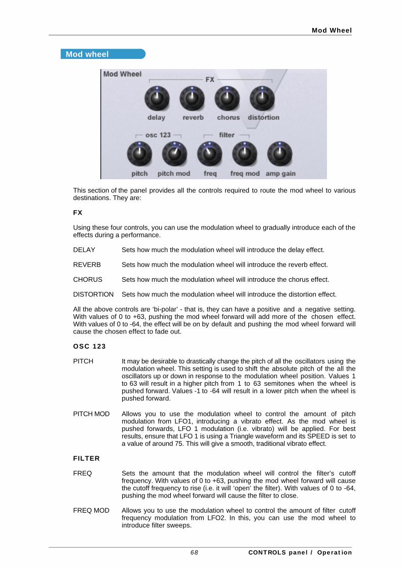
Mod Wheel
Mod wheel
This section of the panel provides all the controls required to route the mod wheel to variousdestinations. They are:
FX
Using these four controls, you can use the modulation wheel to gradually introduce each of theeffects during a performance.
DELAY Sets how much the modulation wheel will introduce the delay effect.
REVERB Sets how much the modulation wheel will introduce the reverb effect.
CHORUS Sets how much the modulation wheel will introduce the chorus effect.
DISTORTION Sets how much the modulation wheel will introduce the distortion effect.
All the above controls are ‘bi-polar’ - that is, they can have a positive and a negative setting.With values of 0 to +63, pushing the mod wheel forward will add more of the chosen effect.With values of 0 to -64, the effect will be on by default and pushing the mod wheel forward willcause the chosen effect to fade out.
OSC 123
PITCH It may be desirable to drastically change the pitch of all the oscillators using themodulation wheel. This setting is used to shift the absolute pitch of the all theoscillators up or down in response to the modulation wheel position. Values 1to 63 will result in a higher pitch from 1 to 63 semitones when the wheel ispushed forward. Values -1 to -64 will result in a lower pitch when the wheel ispushed forward.
PITCH MOD Allows you to use the modulation wheel to control the amount of pitchmodulation from LFO1, introducing a vibrato effect. As the mod wheel ispushed forwards, LFO 1 modulation (i.e. vibrato) will be applied. For bestresults, ensure that LFO 1 is using a Triangle waveform and its SPEED is set toa value of around 75. This will give a smooth, traditional vibrato effect.
FILTER
FREQ Sets the amount that the modulation wheel will control the filter’s cutofffrequency. With values of 0 to +63, pushing the mod wheel forward will causethe cutoff frequency to rise (i.e. it will ‘open’ the filter). With values of 0 to -64,pushing the mod wheel forward will cause the filter to close.
FREQ MOD Allows you to use the modulation wheel to control the amount of filter cutofffrequency modulation from LFO2. In this, you can use the mod wheel tointroduce filter sweeps.
68 CONTROLS panel / Operation

Mod Wheel
AMP
AMP GAIN By routing the Modulation wheel to the amplifier, the overall volume of thesound may be controlled. Positive values of 1 to 63 increase the outputvolume of the Amp Envelope as the Modulation Wheel is pushed forwards.Negative values from -1 to -64 decrease the output volume of the AmpEnvelope as the Modulation Wheel is pushed forwards. At a setting of 0, thewheel will have no effect.
Pitch bend
These three controls allow you to set the pitch bend range for each oscillator individually. Thevalue shown when the controls are adjusted shows the number of semitones the pitch bendwheel will affect the oscillators’ pitch.
Under normal circumstances, each oscillator should be set to the same value. However, byhaving independent control of each oscillator individually, you have an enormous amount offlexibility to set different pitch bend ranges for special performance effects. In fact, oneapplication where this is useful is in the case of using Oscillator Sync. By setting pitch bend onOscillator 1 to zero and a wide pitch bend range to Oscillator 2, you can use the pitch bendwheel to create the tearing sync sweep effect.
69 CONTROLS panel / Operation
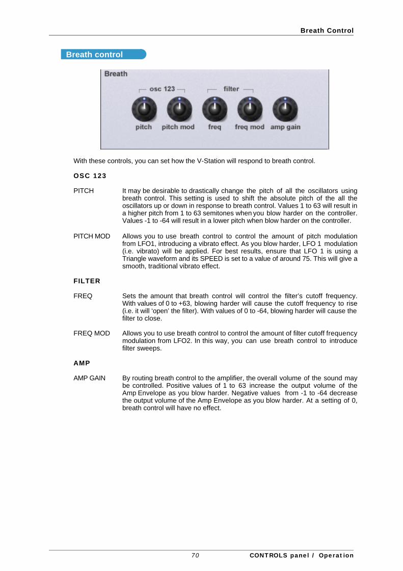
Breath Control
Breath control
With these controls, you can set how the V-Station will respond to breath control.
OSC 123
PITCH It may be desirable to drastically change the pitch of all the oscillators usingbreath control. This setting is used to shift the absolute pitch of the all theoscillators up or down in response to breath control. Values 1 to 63 will result ina higher pitch from 1 to 63 semitones when you blow harder on the controller.Values -1 to -64 will result in a lower pitch when blow harder on the controller.
PITCH MOD Allows you to use breath control to control the amount of pitch modulationfrom LFO1, introducing a vibrato effect. As you blow harder, LFO 1 modulation(i.e. vibrato) will be applied. For best results, ensure that LFO 1 is using aTriangle waveform and its SPEED is set to a value of around 75. This will give asmooth, traditional vibrato effect.
FILTER
FREQ Sets the amount that breath control will control the filter’s cutoff frequency.With values of 0 to +63, blowing harder will cause the cutoff frequency to rise(i.e. it will ‘open’ the filter). With values of 0 to -64, blowing harder will cause thefilter to close.
FREQ MOD Allows you to use breath control to control the amount of filter cutoff frequencymodulation from LFO2. In this way, you can use breath control to introducefilter sweeps.
AMP
AMP GAIN By routing breath control to the amplifier, the overall volume of the sound maybe controlled. Positive values of 1 to 63 increase the output volume of theAmp Envelope as you blow harder. Negative values from -1 to -64 decreasethe output volume of the Amp Envelope as you blow harder. At a setting of 0,breath control will have no effect.
70 CONTROLS panel / Operation

Aftertouch
Aftertouch
With these controls, you can set how the V-Station will respond to aftertouch.
OSC 123
PITCH It may be desirable to drastically change the pitch of all the oscillators usingaftertouch. This setting is used to shift the absolute pitch of the all theoscillators up or down in response to aftertouch. Values 1 to 63 will result in ahigher pitch from 1 to 63 semitones when you press harder on your keyboard.Values -1 to -64 will result in a lower pitch when you press down on yourkeyboard.
PITCH MOD Allows you to use aftertouch to control the amount of pitch modulation fromLFO1, introducing a vibrato effect. As you press down on your keyboard, LFO1 modulation (i.e. vibrato) will be applied. For best results, ensure that LFO 1 isusing a Triangle waveform and its SPEED is set to a value of around 75. Thiswill give a smooth, traditional vibrato effect.
FILTER
FREQ Sets the amount that aftertouch will control the filter’s cutoff frequency. Withvalues of 0 to +63, pressing harder on your keyboard will cause the cutofffrequency to rise (i.e. it will ‘open’ the filter). With values of 0 to -64, pressingharder on your keyboard will cause the filter to close.
FREQ MOD Allows you to use aftertouch to control the amount of filter cutoff frequencymodulation from LFO2. In this way, you can use aftertouch to introduce filtersweeps.
AMP
AMP GAIN By routing aftertouch to the amplifier, the overall volume of the sound may becontrolled. Positive values of 1 to 63 increase the output volume of the AmpEnvelope as you press harder on your keyboard. Negative values from -1 to-64 decrease the output volume of the Amp Envelope as you press down onyour keyboard. At a setting of 0, aftertouch will have no effect.
71 CONTROLS panel / Operation

Global Panel
GLOBAL panel
This page allows you to set parameters that relate to the overall performance of the V-Station.
Global
MASTER TUNE Knob
This allows you to tune the V-Station to other instruments.
SYNC MODE select LEDs
If MIDI Clock Source is set to EXT (external clock), a clock synchronisation type may be selectedusing this function This allows the first note played after all notes have been released or thefirst note played after a MIDI Program Change or MIDI Song Start Message to synchronise thePanning, EQ filter, Chorus LFO’s and voice LFO’s . This allows them to have their start positionlocked in time with the musical piece for stunning effects.
CLOCK SOURCE select LEDs
The V-Station requires a master timing clock in order to determine the tempo (rate) of thearpeggiator and to provide a time base for synchronisation to other musical timings. This clockmay be derived from your host sequencer or can be derived from the V-Station’s own internalclock. Bt default, the V-Station is set to automatically sync to your host sequencer’s tempo.
72 GLOBAL panel / Operation

Global Panel
When set to EXT, the V-Station will sync to the sequencer’s tempo. However, that’s not to sayevery syncable device in the V-Station will run in time with your sequencer - they will have to beindividually set to sync to incoming MIDI clock. The only exception to this is the arpeggiatorwhich, by default, will sync to your sequencer. Perhaps the following diagram will make thingsclearer:
OFF
OFF
OFF
OFF
OFF
OFF
DIVIDER
DIVIDER
DIVIDER
DIVIDER
DIVIDER
DIVIDER
DIVIDER
LFO 1
LFO 2
DELAY TIME
CHORUS LFO
EQ LFO
PANNING LFO
ARPEGGIATOR
CLOCK
The above is the default setting for the V-Station. External sync is selected and, by default, thearpeggiator is synchronised to the sequencer’s tempo. However, the other syncable devicesare, by default, set to free-run at rates determined by their own speed or time controls. If youwant any of the syncable devices to synchronise to the sequencer’s tempo, they should bespecifically set with the device’s SYNC RATE parameter.
Note : Most sequencers do not transmit MIDI Clock while they are stopped. Synchronisation ofthe V-Station to MIDI Clock will only be possible while the sequencer is actually recording orplaying.
When set to INT, the V-Station’s own internal clock is used for synchronisation purposes. Thetempo of the internal clock is controlled by the TEMPO knob found in the Arpeggiator section.
VEL CURVE select LEDs
The response to MIDI velocity information may be set using this function.
A setting of SOFT indicates that smaller changes in velocity (a lighter playing style) will create alarge change in response to velocity, be it volume or any other modulation destination thatvelocity is routed to.
A setting of HARD indicates that higher changes in velocity - a much harder playing style, willcreate large changes in response to velocity.
73 GLOBAL panel / Operation

Memory Restore
Memory
Restoring the factory presets
The RESTORE button allows you to restore the factory sounds originally supplied with theV-Station. To restore the factory sounds, simply click on RESTORE - you will receive a promptasking if you want to restore just the currently selected program or all programs:
Select as appropriate. You will then be asked if you are sure you want to proceed.:
Click on the appropriate response.
Note : The RESTORE process will completely replace the sounds you have in your V-Stationand there is no ‘undo’ function - please proceed with caution if you have created and storedany of your own sounds as they will be lost if you proceed with the RESTORE function.
74 GLOBAL panel / Operation

Import / Export
Import / Export
The V-Station allows you to import sounds from a K-Station and export a MIDI file that can beused to dump your V-Station sounds into a K-Station. The EXPORT function also allows you toback up your V-Station’s internal sounds and/or build up your own personal library of V-Stationsounds.
We’ll discuss EXPORT first and we’ll look at how to get that export into the V-Station and into aK-Station.
To export, click on EXPORT. You will receive this prompt:
You can export the currently selected sound or all programs. Select as appropriate. You willthen receive a typical ‘navigation’ window where you must give the file a name as appropriiateand you should save this to a location of your choosing. You should have something like‘export.mid’ or whatever saved on your hard drive.
To import, click on IMPORT. This will pop-up a typical navigation window:
75 GLOBAL panel / Operation

Import / Export
Select the file you wiant to import and click on IMPORT. After a short while, the V-Station’s LCDwill inform you that the import completed.
Note : The IMPORTprocess will completely replace the sounds you have in your V-Station andthere is no ‘undo’ function - please proceed with caution if you have created and stored any ofyour own sounds as they will be lost if you proceed with the IMPORT function.
Transferring sounds from a V-Station to a K-Station
To transfer sounds from you V-Station to a K-Station, go through the export process describedabove so that you have a MIDI file that contains your sounds. Now, open your sequencer andcreate a new project (song, arrangement or whatever it is your sequencer refers to them as).Now either import the MIDI file you created (i.e. the ‘export.mid’ or whatever it is you called it)into the empty song (or, if your sequencer allows, drag and drop it onto a track). Now, assumingthat you have a MIDI OUT connected from your Mac/PC to the K-Station’s MIDI IN (andassuming the K-Station is switched on!!), press PLAY on your sequencer - the SysEx data willbe sent to the K-Station and the sounds from your V-Station will be transferred.
Note : The K-Station doesn’t have to be in any special mode or condition to receive a SysExdump of sounds - as soon as you put your sequencer into PLAY, assuming the file is valid andthe correct MIDI connections are made, the data will be transferred to the K-Station.
Transferring sounds from a K-Station to a V-Station.
To initiate a Sysex dump, press MENUS and UTILITIES on the K-Station’s front panel - youshould see the ‘DUMP’ utility (if not, use the UP/DOWN keys to select it. Now select thedesired option using the DATA knob - you have several options: CURRENT SOUND,PROGRAM BANKS 1, 2, 3 or 4 or ALL PROGRAM BANKS which can be selected using theDATA knob. Select a track on your sequencer and start the sequencer recording. Now pressthe K-Station’s WRITE button to start transmission of Sysex data. If the CURR SOUND option isselected as the transmission type, then the LCD will flash DONE as confirmation that thetransmission has taken place. If PROG BANK1 through ALL P BANKS is selected as thetransmission type, the display will indicate progress of transmission by indicating DUMPINGPROG XXX (where XXX is the Program number). When you see the ‘DONE’ message on theLCD, you can stop recording on your sequencer.
Note : The V-Station cannot accept a GLOBAL DUMP from the K-Station. If you attempt to trythis, the V-Station will show “Invalid File” in its LCD.
Note : Some sequencers (such as Cubase) sometimes have Sysex messages filtered out as adefault setting. If the sequencer appears not to have recorded the sysex dump into a track,check that the sequencer is not set to filter out Sysex messages. Consult the sequencer’smanual for details.
The selected track you just recorded onto should now have a region shown that contains theK-Station’s SysEx data (you can check this by opening the sequencer’s ‘event list’ window if ithas one). You should now save as or export as a MIDI file with a name of your choosing at alocation of your choosing.
Please consult your sequencer’s documentation for details on saving or exporting MIDI files.
Note : The MIDI file MUST have the extension .mid at the end of the file for it to be used by theV-Station’s IMPORT function.
Now insert the V-Station into a track (or open the V-Station if it’s already inserted) and selectthe GLOBAL page. Click on IMPORT and follow the procedure described on the previouspage.
76 GLOBAL panel / Operation

Import / Export
Importing raw SysEx files from the K-Station to the V-Station
The V-Station will also import SysEx files (*syx) and it is possible (with the appropriateapplication) to import raw sysex data from the K-Station into your computer. In this way, you canreceive K-Station SysEx dumps directly into your computer, save the result as ‘*.syx’ andimport that directly to the V-Station without having to create a MIDI file.
Applications that allow this are:
PC MIDIOX ( http://www.midiox.com ) 3
OSX SYSEX LIBRARIAN ( http://www.snoize.com/SysExLibrarian ) 3
Typically, with the application open, you initiate a SysEx dump from the K-Station. Theapplication will receive the data and will then allow you to save it as a SysEx file which can beimported into the V-Station. You should consult the application’s documentation for exactdetails.
Note : The SysEx file MUST have the extension .syx at the end of the file for it to be used bythe V-Station’s IMPORT function.
3 MIDIOX and SYSEX LIBRARIAN are both 3rd-party applications. They are neither endorsed orsupported by Novation but are mentioned here as examples of SysEx applications. Any issuesor problems you may have with either application must be resolved between you and theapplication’s vendors.
Novation cannot and will not be held responsible for any dispute that may arise betweenyourself and any 3rd-party software vendors.
77 GLOBAL panel / Operation

Preferences
Preferences
In this section, you can set certain preferences. These are:
POT CONTROL select LEDs
You can choose between two different types of controlling the knobs on the V-Station’spanels. With LINEAR selected, moving the mouse up or down will cause the knob to rotate.When ROTARY is selected, you should move the mouse in a circle to rotate the knob.
SUST > ARP LATCH select LEDs
Normally, When the arpeggiator is used on the V-Station, the sustain pedal doesn't work assustain but turns the arpeggiator LATCH function on and off instead. The SUST > ARPfunction controls whether this feature works or not.
If SUST > ARP is ON, the doesn’t work as a sustain pedal but will latch the arpeggiator forhands-free operation.
If SUST > ARP is switched OFF, sustain works like a normal sustain pedal and has no effect onthe arpeggiator latch - this should be switched on/off manually using the LATCH button theEXTRA page.
The remainder of the panel shows details of your V-Station - serial number.
AUTO WRITE select LEDs
This option allows you to select whether loading external sounds into the V-Station will just bestored in memory or actually written to the V-Station’s memory permanently.
When using your host sequencer’s LOAD PRESET function (or BANK or SETTING orwhatever the terminology is that is used by your sequencer), depending on the host, these willonly be loaded into the V-Station’s ‘local’ memory - to store them permanently, they need to bewritten to the V-Station’s memory. This can be done manually, of course, but this preferenceallows you to set the V-Station so that whenever a preset/setting/whatever is loaded, it willautomatically be written to the V-Station’s memory.
You should consult your sequencer’s documentation for details about loading presets/banks.
Another use for this is for automatically writing sounds to memory when you have edited asound. Normally (i.e. AUTO WRITE : OFF), when you edit a sound, should you then select adifferent sound, unless you have specifically written the edited version to the V-Station’smemory, your edits will be lost. With this preference enabled, should you select another soundwhen editing, the edited version will automatically be written before the new sound is selected.
This sounds ideal - when you select a new sound, any edits you might have made to theprevious sound won’t be lost forever. Except.....
You might have edited a sound but made a right hash of it and it sounds worse than the originalyou started off with. So you select another sound - with AUTO-WRITE enabled, your abortiveedit will be written to memory thus overwriting the original sound!
So whilst it’s very useful to be able to auto-save your edits, you can cause problems for yourselfif you’re not careful.
78 GLOBAL panel / Operation

Preferences
NUMPAD PROGRAM SELECT LEDs
This preference allows you to enable program selection using your computer keyboard’snumeric keypad. With this enabled, programs can be selected by typing in a three digit number(100 - 400).
Note : Some sequencers use the numeric keypad for play, stop, locating and other functions.Some sequencers allow you to re-assign these so that you can use the keypad for otherpurposes. Others, however, do not. If your sequencer doesn’t allow you to re-assign thenumeric keypad, you won’t be able to select programs numerically from your keypad. Youshould switch NUMPAD PROGRAM SELECT off.
79 GLOBAL panel / Operation

K-Station control / Automation
Using the V-Station with a K-StationIf you have a K-Station, you can use this to control your V-Station directly and very convenientthis is too as it gives you all the flexibility of a software synth plug-in but with the tactile operationonly a hardware control surface can provide.
Assuming the K-Station is connected to your Mac/PC, insert an instance of the V-Station into atrack. Now, on the K-Station, start fiddling with the front panel controls - you will see thesoftware equivalent knobs moving in real-time as you adjust them on the K-Station. Similarly, asyou press the K-Station’s switches, so the equivalent switches will be ‘pressed’ on theV-Station’s panel.
Furthermore, if you have several instances of the V-Station running, as you switch betweenthem, so the K-Station will control the ‘active’ instance.
What’s more, these control movements can be automated so that they play back every timeyou run the sequencer. Which leads us neatly onto....
Automating control movements on the V-StationOne powerful aspect of synthesizer plug-ins is that control movements can be automated.Typically, as your sequencer is recording, as you move the controls, so their movements areremebered along with the music. When you subsequently rewind and play that sequence, thecontrol movements will be played back. The V-Station is capable of automating the variouspanels’ controls.
Furthermore, if (as described above) you are using a K-Station to control your V-Station, as youtweak the K-Station’s front panel knobs so the V-Station’s controls will move and thesemovements will be recorded into the sequence.
You should consult your sequencer’s documentation for details on automation. Differentsequencers approach automation in a variety of different ways offering different methods ofentering control movements in real-time, different methods of ‘overdubbing’ controlmovements and different ways of edting such movements.
80 K-Station control / Automation

Notes for Logic Users
Notes for Logic usersThere are some issues unique to Emagic’s ‘Logic’ sequencer.
• Logic uses MIDI controllers 7 and 10 for channel level and pan respectively. As a result, it isnot possible to use these controllers to set the level and pan position of the V-Stationitself. If you are using a MIDI controller to issue these control values to control the V-Station’s level and pan, you will find that instead of affaceting the V-Station’s level and pancontrols, you will be setting the selected channel’s level and pan.
• It is not possible to use your Mac keyboard’s numeric keypad to select sounds directly asthese keys are used by Logic for a variety of functions within Logic such as transport,window selection, etc.. At the time of writing, it is not possible to re-assign these functionsto other keys to allow the keypad to be used for program selection on the V-Station.
• It is not possible to save/load individual programs using Logic’s SAVE/LOAD SETTINGS.Logic saves all the V-Station’s programs when SAVE SETTINGS is used. Thus, LOADSETTINGS will load all programs back into the V-Station.
• When the V-Station is inserted into a track, if the V-Station’s window is open and a trackother than the one that the V-Station is inserted into is selected, the V-Station’s panel willappear to be inactive (i.e. the LFOs’ LEDs won’t flash and the voice meter and MIDIRECEIVE LED won’t show anything) even if the V-Station is playing. This is normal withLogic.
81 Notes for Logic Users

MIDI System Exclusive
MIDI controller listSome controllers adhere to the normal midi-specified use (eg modwheel, volume) but most areused arbitrarily and no claim is made of compatibility with other Novation products or othermanufacturer’s products. This is a common practice among manufacturers.
Whilst an attempt has been made to avoid misuse of “standard” controllers which could causeproblems, Novation takes no responsibility for compatibility issues.
Unless noted, controllers are transmitted and received. Unless specifically noted, values havethe range 0-127.
*** denotes a signed value where 64 represents zero.Unless noted, this is -64..0..+63 stored as 0..64..127another example is -12..0..+12 stored as 52..64..76
—- denotes controller not used
Some controllers use the available 7 data value bits to control more than one parameter. Theseare noted as “packed parameters” and details are given.
The term “pulse width” is properly applied when squarewave is selected. For other waveforms,read “pulse width” as “double waveform phase offset”. Double waveform phase offset is zerowhen the signed pulse width position parameter is 64 (meaning 0).
# MIDI-SPECIFIED USE V-STATION USE
0 bank msb IGNORED1 modwheel msb MODWHEEL (receive only)2 breath msb BREATH CONTROL (receive only)3 undefined msb ARP PATTERN (0..5 = up, down, ud1, ud2, order, random)4 foot controller msb —-5 portamento time msb PORTAMENTO TIME6 data entry msb USED FOR NRPN DATA VALUES7 volume msb VOLUME8 balance msb PREGLIDE SEMITONES *** -12..+12 (0=preglide disabled)9 undefined msb ARPEGGIATOR RATE (64..191 bpm)10 pan msb PAN POSITION ***11 expression msb —-12 effect control 1 msb NON-SYNC PAN RATE13 effect control 2 msb SYNC PAN RATE 0..34 (non-sync, 32Triplet..12bars)14 undefined msb —-15 undefined msb —-16 gen. controller 1 msb MODWHEEL DISTORTION ***17 gen. controller 2 msb DISTORTION COMPENSATION18 gen. controller 3 msb MODWHEEL DELAY SEND19 gen. controller 4 msb NON-SYNC DELAY TIME20 undefined msb SYNC DELAY TIME 0..19 (non-sync, 32Triplet..2bars)21 undefined msb DELAY FEEDBACK22 undefined msb DELAY STEREO WIDTH23 undefined msb DELAY RATIO24 undefined msb MODWHEEL REVERB SEND ***25 undefined msb REVERB DECAY26 undefined msb MODWHEEL CHORUS SEND ***27 undefined msb NON-SYNC CHORUS RATE28 undefined msb SYNC CHORUS RATE 0..34 (non-sync, 32Triplet..12bars)29 undefined msb CHORUS FEEDBACK ***30 undefined msb CHORUS MOD DEPTH
i Appendix

MIDI System Exclusive
# MIDI-SPECIFIED USE V-STATION USE
31 undefined msb CHORUS MOD CENTRE POINT32 bank lsb BANK SELECT 1..433 modwheel lsb EQ LEVEL ***
(0, 1..63, 64, 65. 126, 127 = LP, LPshelf, flat, HPshelf, HP)34 breath lsb EQ FREQUENCY35 undefined lsb NON-SYNC EQ MOD RATE36 foot controller lsb SYNC EQ MOD RATE 0..34 (non-sync, 32Triplet..12bars)37 portamento time lsb EQ MOD DEPTH38 data entry lsb —-39 volume lsb —-40 balance lsb OSC1 SEMITONE *** -12..+1241 undefined lsb OSC1 CENT *** -50..+5042 pan lsb OSC1 BENDWHEEL PITCH AMOUNT ***43 expression lsb OSC1 LFO1 PITCH AMOUNT ***44 effect control 1 lsb OSC1 MOD.ENV PITCH AMOUNT ***45 effect control 2 lsb OSC1 PULSE WIDTH POSITION ***
(0=50% or in-phase double wave)46 undefined lsb OSC1 LFO2 PULSE WIDTH MOD ***47 undefined lsb OSC1 MOD.ENV PULSE WIDTH MOD ***48 gen. controller 1 lsb OSC2 SEMITONE *** -12..+1249 gen. controller 2 lsb OSC2 CENT *** -50..+5050 gen. controller 3 lsb OSC2 BENDWHEEL PITCH AMOUNT ***51 gen. controller 4 lsb OSC2 LFO1 PITCH AMOUNT ***52 undefined lsb OSC2 MOD.ENV PITCH AMOUNT ***53 undefined lsb OSC2 PULSE WIDTH POSITION ***
(0=50% or in-phase double wave)54 undefined lsb OSC2 LFO2 PULSE WIDTH MOD ***55 undefined lsb OSC2 MOD.ENV PULSE WIDTH MOD ***56 undefined lsb OSC3 SEMITONE *** -12..+1257 undefined lsb OSC3 CENT *** -50..+5058 undefined lsb OSC3 BENDWHEEL PITCH AMOUNT ***59 undefined lsb OSC3 LFO1 PITCH AMOUNT ***60 undefined lsb OSC3 MOD.ENV PITCH AMOUNT ***61 undefined lsb OSC3 PULSE WIDTH POSITION ***
(0=50% or in-phase double wave)62 undefined lsb OSC3 LFO2 PULSE WIDTH MOD ***63 undefined lsb OSC3 MOD.ENV PULSE WIDTH MOD ***64 sustain pedal SUSTAIN / MOMENTARY ARP LATCH ON65 portamento on/off ENVELOPE MODES / OSC WAVEFORM KEYSYNC
(see packed parameter 1)66 sostenuto pedal —-67 soft pedal UNISON / VOICE TYPE / FILTER TYPE (see packed parameter 2)68 legato footswitch UNISON DETUNE69 hold 2 INDIVIDUAL OSCILLATOR RANDOM DETUNE70 sound controller 1 OSC 1,2,3 WAVEFORM / PORTAMENTO MODE
(see packed parameter 3)71 sound controller 2 OSC 1,2,3 OCTAVE / OSC 1>2 SYNC (see packed parameter 4)72 sound controller 3 OSC1 LEVEL (to filter)73 sound controller 4 OSC2 LEVEL (to filter)74 sound controller 5 OSC3 LEVEL (to filter)75 sound controller 6 NOISE LEVEL (to filter)76 sound controller 7 OSC 1*2 RINGMOD LEVEL (to filter)77 sound controller 8 —-78 sound controller 9 LFO 1,2 WAVEFORM / DELAY MULTI MODE
(see packed parameter 5)
i i Appendix

MIDI System Exclusive
# MIDI-SPECIFIED USE V-STATION USE
79 sound controller 10 LFO 1,2 KEYSYNC / LOCK / PHASE CONTROL(see packed parameter 6)
80 gen. controller 5 lsb NON-SYNC LFO1 SPEED81 gen. controller 6 lsb SYNC LFO1 SPEED (0=NON-SYNC)82 gen. controller 7 lsb LFO1 DELAY (GRADUAL ONSET TIME)83 gen. controller 8 lsb NON-SYNC LFO2 SPEED84 portamento control SYNC LFO2 SPEED (0=NON-SYNC)85 undefined LFO2 DELAY (GRADUAL ONSET TIME)86 undefined —- (may be used in future software releases)87 undefined ARPEGGIATOR SYNC SETTING 0..15 (32Triplet..1 bar)88 undefined ARPEGGIATOR GATE TIME
(100+ GIVES TIED NOTE IN MONO MODE)89 undefined ARPEGGIATOR CONTROL (see packed parameter 7)90 undefined91 effects 1 depth REVERB SEND LEVEL92 effects 2 depth DELAY SEND LEVEL93 effects 3 depth CHORUS SEND LEVEL94 effects 4 depth PAN MOD DEPTH95 effects 5 depth —-96 data increment —-97 data decrement —-98 nrpn lsb NRPN NUMBER99 nrpn msb IGNORED100 rpn lsb —-101 rpn msb —-102 undefined FILTER FREQUENCY LFO2 MOD DEPTH ***103 undefined FILTER Q NORMALISE
(127=zero filter drive at max resonance)104 undefined FILTER OVERDRIVE105 undefined FILTER FREQUENCY106 undefined FILTER RESONANCE107 undefined FILTER FREQUENCY MOD.ENV DEPTH ***108 undefined AMP ENVELOPE ATTACK109 undefined AMP ENVELOPE DECAY110 undefined AMP ENVELOPE SUSTAIN111 undefined AMP ENVELOPE RELEASE112 undefined AMP ENVELOPE VELOCITY DEPTH ***113 undefined —- (may be used in future software releases)114 undefined MOD. ENVELOPE ATTACK115 undefined MOD. ENVELOPE DECAY116 undefined MOD. ENVELOPE SUSTAIN117 undefined MOD. ENVELOPE RELEASE118 undefined MOD. ENVELOPE VELOCITY DEPTH ***119 undefined VOICE LEVEL TO OUTPUT & EFFECTS120 all sounds off ALL NOTES OFF WITH FAST RELEASE
(receive only)121 reset controllers RESET CONTROLLERS (receive only)122 local on/off LOCAL ON/OFF123 all notes off ALL NOTES OFF (receive only)124 omni off ALL NOTES OFF (receive only)125 omni on ALL NOTES OFF (receive only)126 mono mode setup ALL NOTES OFF (receive only)127 poly mode on ALL NOTES OFF (receive only)
i i i Appendix

MIDI System Exclusive
Refer to the lists of MIDI Controllers and NRPNs on Pages 42 - 44.
1 ENVELOPES SINGLE-MULTI / OSC WAVEFORM KEYSYNCbit 0 amp env trigger 0=single 1=multibit 1 mod env trigger 0=single 1=multibit 2 fm env trigger 0=single 1=multibits 3-6 4-bit wave keysync phase
0=free-running 1..15 = 0..336 degrees in 24 degree steps
2 UNISON / POLY MODE / FILTER TYPEbits 0-2 3-bit unison count
0=off 1..7=2..8 voicesbits 3-4 2-bit voice polyphony mode
0=mono 1=mono autoglide 2=poly 3=poly with “same note voice stealing”bit 5 filter type 0=12dB 1=24dB per octave
3 OSC 1/2/3 WAVEFORM / PORTAMENTO MODEbits 0-1 2-bit osc1 waveform sine, tri, saw, square (pulse)bits 2-3 2-bit osc2 waveform sine, tri, saw, square (pulse)bits 4-5 2-bit osc3 waveform sine, tri, saw, square (pulse)bit 6 portamento mode 0=exponential 1=linear
4 OSC 1,2,3 OCTAVE / OSC 1>2 SYNCbits 0-1 2-bit osc1 octave -1,0,1,2bits 2-3 2-bit osc2 octave -1,0,1,2bits 4-5 2-bit osc3 octave -1,0,1,2bit 6 osc1>2 sync 1=on
5 LFO 1,2 WAVEFORM / DELAY MULTI MODEbit 0 lfo1 delay multi 1=onbit 1 lfo2 delay multi 1=onbits 2-3 2-bit lfo1 waveform tri, saw, square, s/hbits 4-5 2-bit lfo2 waveform tri, saw, square, s/h
6 LFO 1,2 KEYSYNC / LOCK / PHASE CONTROLbit 0 lfo1 keysync phase shiftbit 1 lfo1 keysync 1=onbit 2 lfo1 lock 0=independent per voice 1=all voices same phasebit 3 lfo2 keysync phase shiftbit 4 lfo2 keysync 1=onbit 5 lfo2 lock 0=independent per voice 1=all voices same phase
Note that when lock is on, keysync becomes global sync (i.e. note when all notes off, first noteafter prog change, song start message)
7 ARPEGGIATOR CONTROLbits 0-1 2-bit number of octaves 1,2,3,4bit 2 arpeggiator off/on 1=onbit 3 arpeggiator keysync control 1=onbit 4 arpeggiator latch control 1=on
8 EFFECTS TYPE CONTROLbits 0-2 3-bit reverb type Ec Sr Sh Lr Lh gh (values 6,7 not used)bit 3 chorus/phaser control 0=chorus 1=phaser
9 EFFECTS GLOBAL SYNC CONTROLbits 0-1 2-bit chorus global sync off,left,centre,rightbits 2-3 2-bit pan global sync off,left,centre,rightbits 4-5 2-bit eq frequency global sync off,low,mid,high
iv Appendix

MIDI System Exclusive
10 EFFECTS, VOCODER & EXTERNAL AUDIO CONTROLbit 3 vocoder sibilance type 0=hi-pass 1=noisebit 5 external audio trigger control 1=enabledbit 6 external audio to fx control 1=enabled
11 EFFECTS SELECT/ KEYBOARD OCTAVEbits 0-2 0=Delay 1=reverb 2=chorus 3=distortion 4=EQ 5=panning 6=vocoderbit 3,4,5,6 Signed value 0 = Nominal Octave where middle C is 261Hz
-4 = Lowest Octave +5 = Highest octave
12 OSC SELECT, NOISE/RING SELECT, PWM SOURCE SELECT, LFO SELECTbits 0-1 Osc Select 0=1 1=2 2=3bits 2-3 0=Noise 1=Ring1,2 2=External Inputbits 4-5 0=PW Position 1=LFO2 Mod 2=Mod Env Modbits 4-5bit 6 LFO Select 0= LFO1 1=LFO2
v Appendix

MIDI System Exclusive
The V-Station uses a few NRPNs as detailed below. Since less than 128 of them are used, onlyone NRPN msb (bank) is needed. Therefore only the NRPN lsb is transmitted/received and theNRPN msb is ignored and is not transmitted.
For future compatibility, assume that the NRPN msb is 0.
NRPN lsb V-STATION USE
0 FM FIXED LEVEL1 FM ENVELOPE DEPTH ***2 FM ENVELOPE VELOCITY DEPTH ***3 FM ENVELOPE ATTACK4 FM ENVELOPE DECAY5 OSCs 1,2,3 MODWHEEL DIRECT PITCH DEPTH ***6 OSCs 1,2,3 AFTERTOUCH DIRECT PITCH DEPTH ***7 OSCs 1,2,3 BREATH DIRECT PITCH DEPTH ***8 OSCs 1,2,3 MODWHEEL LFO1 PITCH DEPTH ***9 OSCs 1,2,3 AFTERTOUCH LFO1 PITCH DEPTH ***10 OSCs 1,2,3 BREATH LFO1 PITCH DEPTH ***11 FILTER KEYBOARD TRACKING (0=NONE, 127=PRECISE PITCH TRACK)12 FILTER MODWHEEL DIRECT FREQUENCY DEPTH ***13 FILTER AFTERTOUCH DIRECT FREQUENCY DEPTH ***14 FILTER BREATH DIRECT FREQUENCY DEPTH ***15 FILTER MODWHEEL LFO2 FREQUENCY DEPTH ***16 FILTER AFTERTOUCH LFO2 FREQUENCY DEPTH ***17 FILTER BREATH LFO2 FREQUENCY DEPTH ***18 AMPLITUDE MODWHEEL DIRECT DEPTH ***19 AMPLITUDE AFTERTOUCH DIRECT DEPTH ***20 AMPLITUDE BREATH DIRECT DEPTH ***21 EFFECTS TYPE CONTROL (see packed parameter 8)22 EFFECTS GLOBAL SYNC CONTROL (see packed parameter 9)2324 RESERVED25 EFFECTS SELECT/ KEYBOARD OCTAVE (see packed parameter 11)26 OSC SELECT, NOISE/RING SELECT, PWM SOURCE SELECT, LFO SELECT
(see packed parameter 12)27-31 —- (may be used in future software releases)
NRPNs FOR GLOBAL DATA (not part of programs)
32 MIDI RECEIVE CHANNEL 0..1533 MIDI TRANSMIT CHANNEL 0..1534-37 —- (may be used in future software releases)38 MIDI CLOCK SOURCE (0=internal 1=external)39 —- (may be used in future software releases)40 MASTER TUNE CENTS ***41 VELOCITY CURVE (0=soft 1=hard)42 EXTERNAL INPUT RANGE (0=line 1=mic)43 EXTERNAL INPUT TRIM (-10..+20 dB)44 EXTERNAL INPUT TRIGGER SENSITIVITY (0 is most sensitive)45 GLOBAL SYNC TYPE
(0,1,2 = note when all notes off, first note after prog change, midi song start)46 PARAMETER MOMENTARY DISPLAY TIME (off.200..1200mS)47 MENU INITIAL PAGE MODE (0=first 1=last used)48 KEYBOARD TRANSMIT CHANNEL4950 -127 —- (may be used in future software releases)
vi Appendix

MIDI System Exclusive
SYSEX REQUEST MESSAGES (receive only)
PROGRAM DUMP REQUEST
F0h SYSEX START00h NOVATION ID 120h NOVATION ID 229h NOVATION ID 301h DEVICE TYPE41h K-STATIONSyCh SYSEX CHANNEL 7Fh or current receive channel41h MESSAGE TYPE Program dump requestC CONTROL BYTE Reply will copy this value for CVv SOFTWARE VERSION Don't careVi VERSION INCREMENT Don't care
B PROGRAM BANK 1-4 : don't care if C=0P PROGRAM NUMBER 0-99
F7h END OF EXCLUSIVE
PROGRAM PAIR DUMP REQUEST
F0h SYSEX START00h NOVATION ID 120h NOVATION ID 229h NOVATION ID 301h DEVICE TYPE41h K-STATIONSyCh SYSEX CHANNEL 7Fh or current receive channel42h MESSAGE TYPE Program pair dump requestC CONTROL BYTE Reply will copy this value for CVv SOFTWARE VERSION Don't careVi VERSION INCREMENT Don't care
B PROGRAM BANK 1-4 : Don't care if C=0P PROGRAM NUMBER 0,2,4….98
F7h END OF EXCLUSIVE
GLOBAL DATA DUMP REQUEST
F0h SYSEX START00h NOVATION ID 120h NOVATION ID 229h NOVATION ID 301h DEVICE TYPE41h K-STATIONSyCh SYSEX CHANNEL 7Fh or current receive channel43h MESSAGE TYPE Global data dump request00h CONTROL BYTE Don't careVv SOFTWARE VERSION Don't careVi VERSION INCREMENT Ddon't care
00h (PROGRAM BANK) Don't care00h (PROGRAM NUMBER) Don't care
F7h END OF EXCLUSIVE
vi i Appendix

MIDI System Exclusive
GLOBAL DATA BLOCK (256 bytes)
Byte Parameter
0 POWER-UP PROGRAM BANK 1..41 POWER-UP PROGRAM NUMBER 0..992 MEMORY PROTECT (0=protected 1=not protected)3 MIDI LOCAL CONTROL (0=off 127=on)4 MIDI RECEIVE CHANNEL 0..155 MIDI TRANSMIT CHANNEL 0..156-9 --- (may be used in future software releases)10 MIDI CLOCK SOURCE (0=internal 1=external)11 --- (may be used in future software releases)12 MASTER TUNE CENTS ***13 VELOCITY CURVE (0=soft 1=hard)14 EXTERNAL INPUT RANGE (0=line 1=mic)15 EXTERNAL INPUT TRIM (-10..+20 dB)16 EXTERNAL INPUT TRIGGER SENSITIVITY (0 is most sensitive)17 GLOBAL SYNC TYPE
(0,1,2 = note when all notes off, first note after prog change, midi song start)18 PARAMETER MOMENTARY DISPLAY TIME (off.200..1200mS)19 MENU INITIAL PAGE MODE (0=first 1=last used)20 KEYBOARD/WHEELS MIDI TRANSMIT CHANNEL 0..1521 PROGRAM MODE PARAMETER DISPLAY MODE (0=timed 1=permanent)22 KEYBOARD OCTAVE SHIFT ALL-NOTES-OFF CONTROL
(0=off 1=kill notes & send midi all-notes-off)
23-255--- (may be used in future software releases)Zeros are transmitted. Use zeros for future compatibility
DATA BLOCKS USED IN SYSEX MESSAGES
See Midi Controller Map for further details of parameters and meaning of ***.
PROGRAM DATA BLOCK (128 bytes)
Byte Parameter
0 UNISON / VOICE TYPE / FILTER TYPE (see packed parameter 2)1 UNISON DETUNE2 INDIVIDUAL OSCILLATOR RANDOM DETUNE3 PORTAMENTO TIME4 PREGLIDE SEMITONES *** -12..+12 (0=preglide disabled)5 OSC 1,2,3 WAVEFORM / PORTAMENTO MODE (see packed parameter 3)6 OSC 1,2,3 OCTAVE / OSC 1>2 SYNC (see packed parameter 4)
7 OSC1 SEMITONE *** -12..+128 OSC1 CENT *** -50..+509 OSC1 BENDWHEEL PITCH AMOUNT ***10 OSC1 LFO1 PITCH AMOUNT ***11 OSC1 MOD.ENV PITCH AMOUNT ***12 OSC1 PULSE WIDTH POSITION *** (0=50% or in-phase double wave)13 OSC1 LFO2 PULSE WIDTH MOD ***14 OSC1 MOD.ENV PULSE WIDTH MOD ***
15 OSC2 SEMITONE *** -12..+1216 OSC2 CENT *** -50..+5017 OSC2 BENDWHEEL PITCH AMOUNT ***18 OSC2 LFO1 PITCH AMOUNT ***Byte Parameter
19 OSC2 MOD.ENV PITCH AMOUNT ***20 OSC2 PULSE WIDTH POSITION *** (0=50% or in-phase double wave)21 OSC2 LFO2 PULSE WIDTH MOD ***22 OSC2 MOD.ENV PULSE WIDTH MOD ***
vi i i Appendix
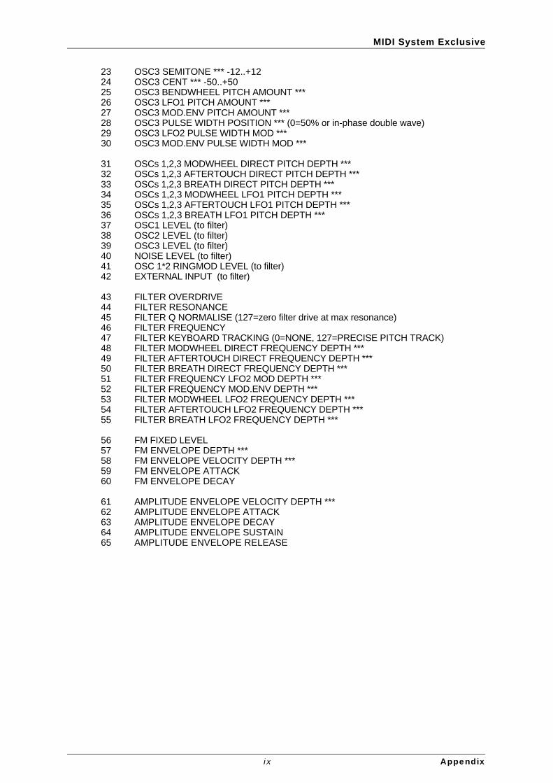
MIDI System Exclusive
23 OSC3 SEMITONE *** -12..+1224 OSC3 CENT *** -50..+5025 OSC3 BENDWHEEL PITCH AMOUNT ***26 OSC3 LFO1 PITCH AMOUNT ***27 OSC3 MOD.ENV PITCH AMOUNT ***28 OSC3 PULSE WIDTH POSITION *** (0=50% or in-phase double wave)29 OSC3 LFO2 PULSE WIDTH MOD ***30 OSC3 MOD.ENV PULSE WIDTH MOD ***
31 OSCs 1,2,3 MODWHEEL DIRECT PITCH DEPTH ***32 OSCs 1,2,3 AFTERTOUCH DIRECT PITCH DEPTH ***33 OSCs 1,2,3 BREATH DIRECT PITCH DEPTH ***34 OSCs 1,2,3 MODWHEEL LFO1 PITCH DEPTH ***35 OSCs 1,2,3 AFTERTOUCH LFO1 PITCH DEPTH ***36 OSCs 1,2,3 BREATH LFO1 PITCH DEPTH ***37 OSC1 LEVEL (to filter)38 OSC2 LEVEL (to filter)39 OSC3 LEVEL (to filter)40 NOISE LEVEL (to filter)41 OSC 1*2 RINGMOD LEVEL (to filter)42 EXTERNAL INPUT (to filter)
43 FILTER OVERDRIVE44 FILTER RESONANCE45 FILTER Q NORMALISE (127=zero filter drive at max resonance)46 FILTER FREQUENCY47 FILTER KEYBOARD TRACKING (0=NONE, 127=PRECISE PITCH TRACK)48 FILTER MODWHEEL DIRECT FREQUENCY DEPTH ***49 FILTER AFTERTOUCH DIRECT FREQUENCY DEPTH ***50 FILTER BREATH DIRECT FREQUENCY DEPTH ***51 FILTER FREQUENCY LFO2 MOD DEPTH ***52 FILTER FREQUENCY MOD.ENV DEPTH ***53 FILTER MODWHEEL LFO2 FREQUENCY DEPTH ***54 FILTER AFTERTOUCH LFO2 FREQUENCY DEPTH ***55 FILTER BREATH LFO2 FREQUENCY DEPTH ***
56 FM FIXED LEVEL57 FM ENVELOPE DEPTH ***58 FM ENVELOPE VELOCITY DEPTH ***59 FM ENVELOPE ATTACK60 FM ENVELOPE DECAY
61 AMPLITUDE ENVELOPE VELOCITY DEPTH ***62 AMPLITUDE ENVELOPE ATTACK63 AMPLITUDE ENVELOPE DECAY64 AMPLITUDE ENVELOPE SUSTAIN65 AMPLITUDE ENVELOPE RELEASE
i x Appendix

MIDI System Exclusive
Byte Parameter
66 MOD. ENVELOPE VELOCITY DEPTH ***67 MOD. ENVELOPE ATTACK68 MOD. ENVELOPE DECAY69 MOD. ENVELOPE SUSTAIN70 MOD. ENVELOPE RELEASE71 --- (may be used in future software releases)
72 NON-SYNC LFO1 SPEED73 SYNC LFO1 SPEED (0=NON-SYNC)74 LFO1 DELAY (GRADUAL ONSET TIME)
75 NON-SYNC LFO2 SPEED76 SYNC LFO2 SPEED (0=NON-SYNC)77 LFO2 DELAY (GRADUAL ONSET TIME)
78 LFO 1,2 WAVEFORM / DELAY MULTI MODE (see packed parameter 5)79 LFO 1,2 KEYSYNC / LOCK / PHASE CONTROL (see packed parameter 6)
80 ENVELOPE MODES / OSC WAVEFORM KEYSYNC (see packed parameter 1)
81 AMPLITUDE MODWHEEL DIRECT DEPTH ***82 AMPLITUDE AFTERTOUCH DIRECT DEPTH ***83 AMPLITUDE BREATH DIRECT DEPTH ***
84 ARPEGGIATOR/GENERAL SYNC RATE (64..191 bpm)85 ARPEGGIATOR SYNC SETTING 0..15 (32Triplet..1 bar)86 ARPEGGIATOR GATE TIME (100+ GIVES TIED NOTE IN MONO MODE)87 ARP PATTERN (0..5 = up, down, ud1, ud2, order, random)88 ARPEGGIATOR CONTROL (see packed parameter 7)
89 VOCODER BALANCE (0=off 64=full vocoder 127=modulator only)90 VOCODER STEREO WIDTH91 VOCODER SIBILANCE LEVEL92 EQ LEVEL *** (0, 1..63, 64, 65..126, 127 = LP, LP shelf, flat, HP shelf, HP)
93 EQ FREQUENCY94 NON-SYNC EQ MOD RATE95 SYNC EQ MOD RATE 0..34 (non-sync, 32Triplet..12bars)96 EQ MOD DEPTH
97 DISTORTION LEVEL98 MODWHEEL DISTORTION ***99 DISTORTION COMPENSATION
100 DELAY SEND LEVEL101 MODWHEEL DELAY SEND102 NON-SYNC DELAY TIME103 SYNC DELAY TIME 0..19 (non-sync, 32Triplet..2bars)104 DELAY FEEDBACK105 DELAY STEREO WIDTH106 DELAY RATIO
107 REVERB SEND LEVEL108 MODWHEEL REVERB SEND ***109 REVERB DECAY
x Appendix
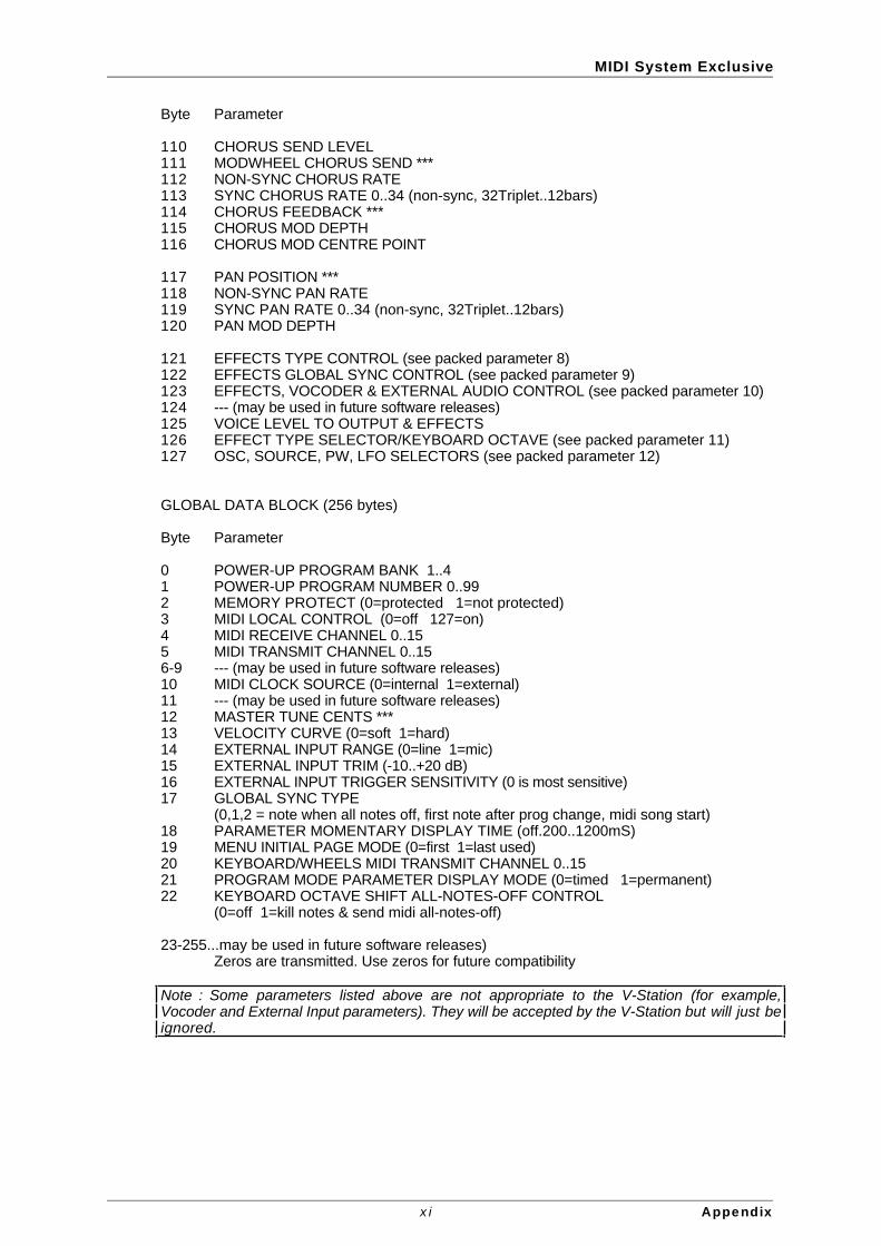
MIDI System Exclusive
Byte Parameter
110 CHORUS SEND LEVEL111 MODWHEEL CHORUS SEND ***112 NON-SYNC CHORUS RATE113 SYNC CHORUS RATE 0..34 (non-sync, 32Triplet..12bars)114 CHORUS FEEDBACK ***115 CHORUS MOD DEPTH116 CHORUS MOD CENTRE POINT
117 PAN POSITION ***118 NON-SYNC PAN RATE119 SYNC PAN RATE 0..34 (non-sync, 32Triplet..12bars)120 PAN MOD DEPTH
121 EFFECTS TYPE CONTROL (see packed parameter 8)122 EFFECTS GLOBAL SYNC CONTROL (see packed parameter 9)123 EFFECTS, VOCODER & EXTERNAL AUDIO CONTROL (see packed parameter 10)124 --- (may be used in future software releases)125 VOICE LEVEL TO OUTPUT & EFFECTS126 EFFECT TYPE SELECTOR/KEYBOARD OCTAVE (see packed parameter 11)127 OSC, SOURCE, PW, LFO SELECTORS (see packed parameter 12)
GLOBAL DATA BLOCK (256 bytes)
Byte Parameter
0 POWER-UP PROGRAM BANK 1..41 POWER-UP PROGRAM NUMBER 0..992 MEMORY PROTECT (0=protected 1=not protected)3 MIDI LOCAL CONTROL (0=off 127=on)4 MIDI RECEIVE CHANNEL 0..155 MIDI TRANSMIT CHANNEL 0..156-9 --- (may be used in future software releases)10 MIDI CLOCK SOURCE (0=internal 1=external)11 --- (may be used in future software releases)12 MASTER TUNE CENTS ***13 VELOCITY CURVE (0=soft 1=hard)14 EXTERNAL INPUT RANGE (0=line 1=mic)15 EXTERNAL INPUT TRIM (-10..+20 dB)16 EXTERNAL INPUT TRIGGER SENSITIVITY (0 is most sensitive)17 GLOBAL SYNC TYPE
(0,1,2 = note when all notes off, first note after prog change, midi song start)18 PARAMETER MOMENTARY DISPLAY TIME (off.200..1200mS)19 MENU INITIAL PAGE MODE (0=first 1=last used)20 KEYBOARD/WHEELS MIDI TRANSMIT CHANNEL 0..1521 PROGRAM MODE PARAMETER DISPLAY MODE (0=timed 1=permanent)22 KEYBOARD OCTAVE SHIFT ALL-NOTES-OFF CONTROL
(0=off 1=kill notes & send midi all-notes-off)
23-255...may be used in future software releases)Zeros are transmitted. Use zeros for future compatibility
Note : Some parameters listed above are not appropriate to the V-Station (for example,Vocoder and External Input parameters). They will be accepted by the V-Station but will just beignored.
x i Appendix

MIDI Implementation
Model : Novation V-Station Version : 1.0
Function Recognised Remarks
Basic 1 - 16 Memorised Channel 1 - 16 Mode Default MODE 3 - 4 Memorised in Program Data
Messages X Altered
Note True 0 -127
Number Voice
Velocity Note On O v = 1 - 127
Note Off X
Aftertouch
Keys X Channel O
Pitch Bend O 8 Bit data
Control Change 1 - 3, 5 - 10 See Controller & NRPN 12 - 37, 40 - 65 tables for full details 67 - 85, 87 - 89 91 - 95, 98, 100 102 - 112, 114 - 127
Program 0 - 99 Change True
System Exclusive O Program & Global data dumps, OS upgrades
System Real-Time O Start Song, Clock
System Common X
Aux Local On O Messages
All Notes Off O Active Sense X Reset Control O All Sound Off O
Default Changed
Mode 1 : OMNI ON, POLY Mode 2 : OMNI ON, MONO O:YesMode 3 : OMNI OFF, POLY Mode 4 : OMNI OFF, MONO X:No
xi i Appendix