mah21 service supplement a1 - amazon s3 · attached is supplement three for service manual...
TRANSCRIPT
16008203-03 ©2002 Maytag Appliances
1
INTRODUCTION
Attached is Supplement three for service manual 16008203. We suggest you file this withyour 16008203 Manual for reference.
Models covered in this manual:MAH21PD MAH21PN MAH21PR MAH21PS
CONTENTS
SECTION 1. Product Definition ........................................................ 2
SECTION 2. Input Modifications Defined .......................................................... 2
SECTION 3. Output Modifications Defined ....................................................... 3
SECTION 4. Revised Door Lock Operation ......................................... 3
SECTION 5. Teardown ................................................................... 4
Door Latch Hoop.......................................................... 4
Door Lock Mechanism ................................................... 4
Rear Access Panel........................................................ 4
Pressure Switch ........................................................... 5
Sump Cover ................................................................. 5
SECTION 6. Dispenser.................................................................... 6
SECTION 7. Motor and Motor Control ................................................ 6
SECTION 8. Trouble Shooting .......................................................... 8
SECTION 9. Wiring Information ....................................................... 10

16008203-03 2 ©2002 Maytag Appliances
• The door locking mechanism was updatedfrom a wax motor drive system to a sole-noid, resulting in faster locking and unlock-ing of the door. However, a wax motor isinstalled in the door lock mechanism forthe sole purpose of unlocking the door inthe event of a power failure. Figure 2
• The water level pressure switch wasrelocated from the console to the top of thepump, thus eliminating the airdome hose.Figure 6
SECTION 2. INPUT MODIFICATIONS DEFINED
PRESSURE SWITCH INPUTThe pressure switch is a two level pressureswitch. (Figure 1) The low level contactsprovide a path for a 24 VDC sensing circuit,the high level contacts provide an electricalpath for 120 VAC to the water valve relayson the board. Another sensor on the boardmonitors the high level circuit to determinewhen the high level is reached and thecircuit is opened.
During wash fill, the low level of thepressure switch is sensed (with 24 VDC)and provides an indication to the controlboard that
Figure 1
• A special sump cap is placed directly abovethe sump area which catches the detergentand allows for a better mixing of the deter-gent and the wash water. This eliminatesthe need for a separate recirculation pump.Figure 8
• Mid 2002 will introduce a different drivemotor system called an electronicallycommustatic induction motor. The operationwill be similar but the controls will be differ-ent.
the water level has satisfied the low levelsetting. Once satisfied, the 24 VDC circuit isopened. The board then opens the watervalve relays and shuts off the water valves.
During rinse fill, the high level provides anindication to the machine control as towhether the high water level has beenreached. When the water level switch issatisfied, the pressure switch circuit isopened and power for the water valves is nolonger passed through the machine control.
SECTION 1. PRODUCT DEFINITION:The model MAH21 is similar to the MAH20 washer, with the following exceptions:

16008203-03 ©2002 Maytag Appliances
3
DOOR LOCK/UNLOCK SOLENOID OUTPUTThe Door Lock/Unlock Solenoid Outputsignal is a 60 millisecond pulse sent to apush-pull solenoid in the door lockassembly. The solenoid is attached to alever which moves a slider in themechanism to lock the door. The solenoidhas two coils, one for locking and one forunlocking. Power is not continuouslyapplied to the solenoid.
Revised Door Lock OperationWhen the door is closed, the hoop on thedoor enters the opening at the bottom ofthe door lock assembly and meshes withfingers on the rotating cam. As the cam isrotated back past center a strong springtoggles the cam to the back thus drawingthe door tightly closed. At the same time,the door inner liner presses an actuatorbutton on the door lock assembly. Thisactuator causes a rocker arm to release thedoor switch button. The door switch(which is a single pole, double throwswitch) toggles to the door-closed position.
At this time nothing further happens until acycle is started.
When a cycle is started the main controlboard will first energize the wax motor (itis located at the right side of the door lockassembly). The wax motor operation doesnot cause the door to lock. Its’ main pur-pose is to assure release of the door lock inthe event of a power failure.
Approximately two minutes after the dooris closed and a cycle is started the controlsends a very short pulse of 120 volt AC tothe door-locking coil of the dual solenoid.
The solenoid pulls an actuator arm which inturn pushes a slider to the right to block
the rotating cam (which locks the door)and as the actuator arm moves it alsoactuates the spin enable (door-locked)switch.
One of the new features on the MAH21control is a “notification” to the user whenthe door is not locked for any reason. Thewords “DOOR LOCKED” in the display willblink rapidly or “flutter”. A D17 will be postedin the fault codes as well.
The door lock sequence will be repeated fora number of times (up to seven) in an at-tempt to lock the door. Should that fail, thecycle will be paused and “RESELECTCYCLE” will be posted in the display. Thewax motor will be released and will cool. Asthe wax motor cools its’ piston will be drawnback which will result in the door lock sliderbeing pushed back to the left and to theunlocked position.
At the end of the cycle, as the coast-downfrom spin begins, the wax motor is releasedand begins to cool. After the “shake-outsequence” of reverse tumble, the controlsends a short 120 volt AC pulse to the doorrelease coil. The door release coil will pushthe solenoid armature back out which willpush the actuator arm back to the unlockedposition. This pulls the slider away from therotating cam and releases the spin enableswitch (door-locked switch). The door maythen be pulled open.
Depending on how quickly the wax motorcools, the actual release of the door can befrom either the wax motor or the door re-lease solenoid.
If a door lock solenoid fails the door ofcourse would not lock; the spin enableswitch would not be made. After severalattempts to lock the door fail the displaywould “flutter’ the “DOOR LOCKED” displayand then would pause the cycle.RESELECT CYCLE would be displayed.
SECTION 3. OUTPUT MODIFICATIONSDEFINED
SECTION 4. DOOR LOCK

16008203-03 4 ©2002 Maytag Appliances
SECTION 5. TEARDOWNDOOR LATCH HOOPThe latch hoop was redesigned, eliminatingthe latch hoop support and spring.
Removal1. Remove the door assembly from the
washer.2. Disassemble the door assembly by
removing the outer door panel.3. Locate the locking tab on the door latch
hoop and pry the tab up. Figure 24. Squeeze the side tabs to disengage the
locating pins on the sides of the latchhoop from the door liner.
5. Reinstallation is a reversal of the afore-mentioned steps.
Figure 2
DOOR LOCK MECHANISMRemoval1. Disconnect power to the washer.2. Remove the front panel, dispenser bezel
and lift the top cover to expose the doorlock assembly.
3. Remove the individual wire harnessesfrom the assembly and the two mount-ing screws. Figure 3
4. Roll the top of the door lock assemblyforward and lift from the front shroudassembly.
Figure 3
REAR ACCESS PANELRemoval of the access panel gains accessto the rear components of the washer.Figure 5
Figure 5
Remove 2 Screws
Figure 4
16008203-03 ©2002 Maytag Appliances
5
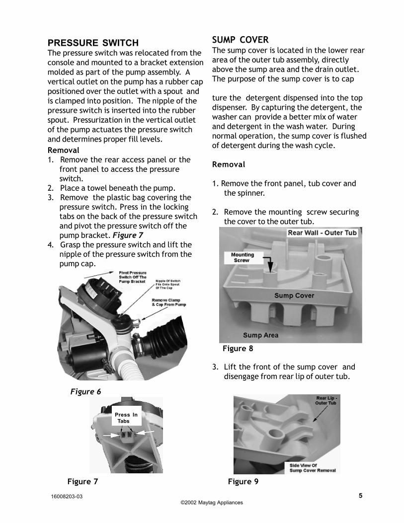
PRESSURE SWITCHThe pressure switch was relocated from theconsole and mounted to a bracket extensionmolded as part of the pump assembly. Avertical outlet on the pump has a rubber cappositioned over the outlet with a spout andis clamped into position. The nipple of thepressure switch is inserted into the rubberspout. Pressurization in the vertical outletof the pump actuates the pressure switchand determines proper fill levels.Removal1. Remove the rear access panel or the
front panel to access the pressureswitch.
2. Place a towel beneath the pump.3. Remove the plastic bag covering the
pressure switch. Press in the lockingtabs on the back of the pressure switchand pivot the pressure switch off thepump bracket. Figure 7
4. Grasp the pressure switch and lift thenipple of the pressure switch from thepump cap.
Figure 6
Figure 7
SUMP COVERThe sump cover is located in the lower reararea of the outer tub assembly, directlyabove the sump area and the drain outlet.The purpose of the sump cover is to cap
ture the detergent dispensed into the topdispenser. By capturing the detergent, thewasher can provide a better mix of waterand detergent in the wash water. Duringnormal operation, the sump cover is flushedof detergent during the wash cycle.
Removal
1. Remove the front panel, tub cover andthe spinner.
2. Remove the mounting screw securingthe cover to the outer tub.
Figure 8
Press In Tabs
3. Lift the front of the sump cover anddisengage from rear lip of outer tub.
Figure 9
16008203-03 6 ©2002 Maytag Appliances
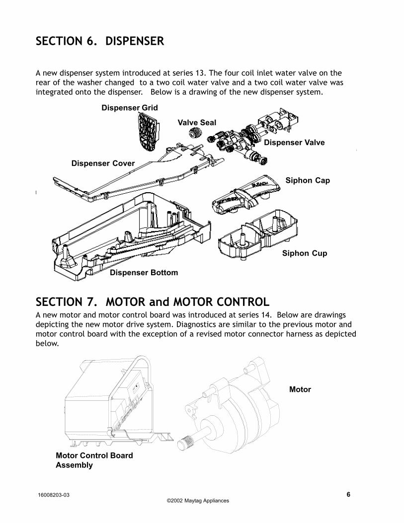
SECTION 6. DISPENSER
SECTION 7. MOTOR and MOTOR CONTROL
A new dispenser system introduced at series 13. The four coil inlet water valve on therear of the washer changed to a two coil water valve and a two coil water valve wasintegrated onto the dispenser. Below is a drawing of the new dispenser system.
Siphon Cap
Siphon Cup
Dispenser Bottom
Dispenser Cover
Dispenser Grid
Dispenser Valve
Motor Control BoardAssembly
Motor
A new motor and motor control board was introduced at series 14. Below are drawingsdepicting the new motor drive system. Diagnostics are similar to the previous motor andmotor control board with the exception of a revised motor connector harness as depictedbelow.
Valve Seal
16008203-03 ©2002 Maytag Appliances
7
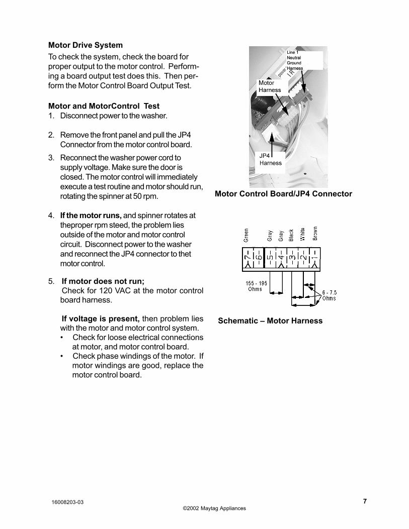
Motor Control Board/JP4 Connector
Schematic – Motor Harness
Motor Drive SystemTo check the system, check the board forproper output to the motor control. Perform-ing a board output test does this. Then per-form the Motor Control Board Output Test.
Motor and MotorControl Test1. Disconnect power to the washer.
2. Remove the front panel and pull the JP4Connector from the motor control board.
3. Reconnect the washer power cord tosupply voltage. Make sure the door isclosed. The motor control will immediatelyexecute a test routine and motor should run,rotating the spinner at 50 rpm.
4. If the motor runs, and spinner rotates attheproper rpm steed, the problem liesoutside of the motor and motor controlcircuit. Disconnect power to the washerand reconnect the JP4 connector to thetmotor control.
5. If motor does not run;Check for 120 VAC at the motor controlboard harness.
If voltage is present, then problem lieswith the motor and motor control system.• Check for loose electrical connections
at motor, and motor control board.• Check phase windings of the motor. If
motor windings are good, replace themotor control board.

16008203-03 8 ©2002 Maytag Appliances
Leaking• Make sure supply hose connections are
not leaking. Check for rubber gasketdamage due to overtightening.
• Make sure end of drain hose is correctlyinserted and secured to drain facility.
• Avoid overloading which can push thedoor partially open.
• Check internal hose connections• Check tub cover. Remove, reposition and
reinstall the tub cover seal. Seal seammust be at the top of the tub cover.
No Tumble• Washer does not tumble for the first 30
seconds after the door has been openedfor safety purposes.
• Check for loose connections at machinecontrol board, motor control board andmotor.
• Perform Motor and Motor Control Test.• Washer does not tumble during some
drains and rinse fills.
No Water Fill• Check to make sure water supply turned on
fully.• Normal water level is only 2.5 to 5 inches
inside the spinner.• Check for kinks in inlet hoses.• Check for clogged inlet screens.• Visually check hot and cold separately at
dispenser for proper flows.
Noisy• Clothes washer should be leveled prop-
erly as outlined in installation instructions.bracket.
• Weak floors can cause vibration andwalking.
• Check for loose lower front weight• Be sure rubber feet are installed on
leveling legs.• Check that the leveling leg lock nuts are
tightened.
SECTION 8. TROUBLESHOOTING GUIDE
• If complaint is a high-pitched noise duringfill then disconnect supply hoses andclean screens.
• Check for proper spring placement ofouter tub support springs.
• Check strut operation.
Tub is completely full of suds• Run the clothes washer through another
complete cycle using cold water and nomore detergent.
• Reduce detergent amount for that specificload size and soil level. Towel loads havea minimal amount of soil present and typi-cally create more suds.
• Use high efficiency or low sudsing deter-gent specially formulated for front loadwashers.
• Check for restricted drain system.• Check for loose wire connections at con-
trol board and pump.• Check to see if belt fell off motor and pul-
ley.• Perform Motor and Motor Control Test.
Wet Clothes• Very small clothes loads can cause
unbalances - add aditional towels.• Excessive suds may have been present.
Check for diagnostic code 16.• Check unbalance harness connections at
all switches and at main harness connec-tion on top of outer tub assembly.
• Inertial unbalance switch tripped toosoon, resulting in lower spin speeds.
• Check for restricted drain system.• Perform Motor and Motor Control Test.
Will Not Lock• Door not all the way closed.• Check electrical connections at lock as-
sembly and machine control board.
16008203-03 ©2002 Maytag Appliances
9
Will Not Unlock• Unplug and replug in power cord and wait
2 minutes to see if machine unlocks.• Check for door locked switch circuit to be
closed at machine control.• Check to make sure belt has not fallen off.• Check for loose electrical connections at
door lock and at machine control board.• Perform Motor and Motor Control Test.
Will Not Start• Plug cord into live electrical outlet.• Check fuse or reset circuit breaker.• Check for restricted drain system.
Will Not Drain• Check for restricted drain system.• Check low and high water levels. Go to No
Fill test• Check for 120 VAC at the pump when a
spin cycle is selected.
Wrong Water Temperature• Too Hot/Too Cold; since this product uses
a low amount of water, the board regu-lates the incoming flow to temper theactual temperature of the water in the tub.This may appear to be significantlywarmer/cooler than expected.
• Are both faucets on fully?• Make sure temperature selection is
correct.• Make sure hoses are connected to
correct faucets and inlet connections.Flush water line before filling washer.
• Check the water heater. It should be setto deliver a minimum 120°F (49°C) hotwater at the tap. Also check water heatercapacity and recovery rate.
• If the water heater is located a longdistance from washer, water line mayneed to be purged prior to starting washcycle.
• Disconnect inlet hoses and cleanscreens.
16008203-03 10 ©2002 Maytag Appliances
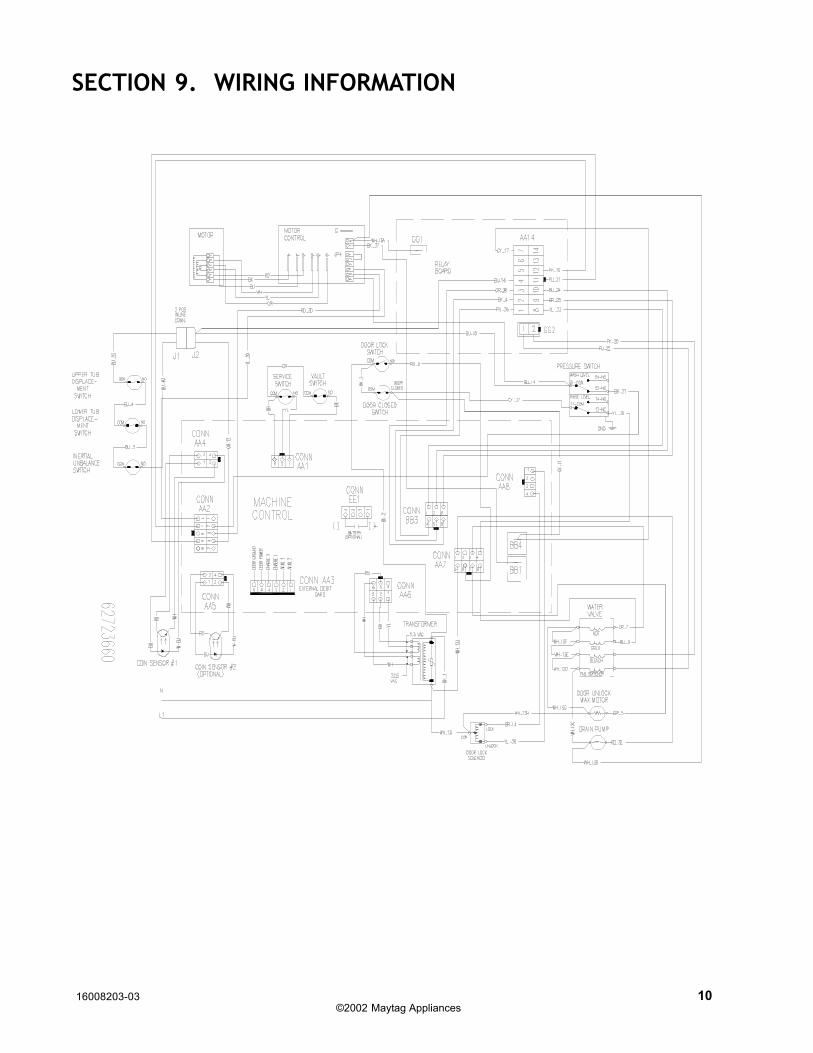
SECTION 9. WIRING INFORMATION