magnum - yahoo · 26d4750 9. the installation must conform with local codes or, in the absence of...
TRANSCRIPT

For use with a listed gas-fired unvented decorative room heater not to exceed 40,000 BTU/hr. Do Not Build a Wood Fire.
READ AND SAVE THESE INSTRUCTIONS
WARNINGSIf the information in this manual is not followed exactly, a fire or explosion may result causing property damage, personal injury or loss of life.
– Do not store or use gasoline or other flammable vapors and liquids in the vicinity of this or any other appliance.
– WHAT TO DO IF YOU SMELL GAS
• Do not try to light any appliance. • Do not touch any electrical switch; do not use any
phone in your building. • Immediately call your gas supplier from a neighbor's
phone. Follow the gas supplier's instructions. • If you cannot reach your gas supplier, call the fire
department.
– Installation and service must be performed by a qualified installer, service agency or the gas supplier.
MAGNUMUNVENTED
VENT-FREE FIREBOXES INSTALLATION AND
OPERATING INSTRUCTIONS
Carefully review the instructions supplied with the decorative type unvented room heater for the mini-mum fireplace size requirement.
DO NOT INSTALL AN APPLIANCE IN THIS FIREBOX UNLESS THIS FIREBOX MEETS THE MINIMUM DIMENSIONS REqUIRED FOR THE INSTALLATION.
WARNINGS
If the information in this manual is not followed exactly, a fire or explosion may result causing property damage, personal injury or loss of life.
– Do not store or use gasoline or other flammable vapors and liquids in the vicinity of this or any other appliance.
– WHAT TO DO IF YOU SMELL GAS • Do not try to light any appliance. • Do not touch any electrical switch; do not use
any phone in your building. • Immediately call your gas supplier from a
neighbor's phone. Follow the gas supplier's instructions.
• If you cannot reach your gas supplier, call the fire department.
– Installation and service must be performed by a qualified installer, service agency or the gas supplier.
WARNINGS
MODELS: 36MCUFD, 42MCUFD SERIES
� 26D4750
CONTENTS
Important Safety Information ................................. 3Product Features ......................................................5 BeforeYouStart.....................................................5General Installation Information .............................6 FireboxDimensions...............................................6 MinimumHearthDimensions.................................7Location of Firebox ..................................................7Clearances and Height Requirements ....................8Fireplace Framing...................................................10Gas Line Installation ..............................................12
Canopy Installation ................................................13Optional Equipment ...............................................14 ForcedAirKit.......................................................14 BrassorChromeTrim..........................................14 OptionalWideCanopy.........................................14Illustrated Parts Breakdown ..................................15Using Optional Outside Air Kit ..............................16Warranty ..................................................Back Cover

26D4750 �
9. The installationmustconformwith localcodesor, intheabsenceoflocalcodes,withtheNational Fuel Gas Code, ANSI Z223.l/NFPA54.
10.ThisunitcomplieswithANSIZ21.91.2001ventlessfire-boxenclosuresforgas-firedunventeddecorativeroomheaters.
11. Donotinstallheaterinabathroomorbedroom.
12. Correct installation of the ceramicfiber logs, properlocationof theheater,andannualcleaningareneces-sarytoavoidpotentialproblemswithsooting.Sooting,resulting from improper installationoroperation,cansettleonsurfacesoutsidethefireplace.Seelogplacementinstructionsforproperinstallation.
13. Avoidanydraftsthatalterburnerflamepatterns.Donotallowfanstoblowdirectlyintofireplace.Donotplaceablowerinsideburnareaoffirebox.Ceilingfansmaycreatedraftsthatalterburnerflamepatterns.Sootingandimproperburningwilloccur.
14. Caution: Candles, incense, oil lamps, etc. producecombustionbyproductsincludingsoot.Vent-freeappli-anceswillnotfilterorcleansootproducedbythesetypesof products. In addition, the smoke and/or aromatics(scents)maybereburntinthevent-freeappliancewhichcanproduceodors.Itisrecommendedtominimizetheuseofcandles,incense,etc.whilethevent-freeapplianceisinoperation.
15. Anunventedgas-firedheaterusesair(oxygen)fromtheroominwhich it is installed.Provisions foradequatecombustionandventilationairmustbeprovided.Seeinstallationguidelines.
INSTALLERPleaseleavetheseinstructionswiththeappliance.
OWNERPleaseretaintheseinstructionsforfuturereference.
IMPORTANTRead these instructions carefully before installing or trying to operate a vent-free gas heater in this firebox.
IMPORTANT SAFETY INFORMATION
1. Duetohightemperatures,theapplianceshouldbelocatedoutoftrafficandawayfromfurnitureanddraperies.
2. Childrenandadultsshouldbealertedtothehazardofhighsurfacetemperatureandshouldstayawaytoavoidburnsorclothingignition.
3. Young children should be carefully supervisedwhen they are in the same roomwith the appli-ance.
4. Donotplaceclothingorotherflammablematerialonorneartheappliance.
5. Anysafetyscreenorguardremovedforservicinganappliance,mustbereplacedpriortooperatingtheheater.
6. Installationandrepairshouldbedonebyaqualifiedserviceperson.
7.Topreventmalfunctionand/orsooting,anunventedgas heater should be cleaned before use at leastannually by a professional service person. Morefrequentcleaningmayberequireddue toexces-sivelintfromcarpeting,beddingmaterial,etc.Itisimperativethatcontrolcompartments,burnersandcirculatingairpassagewaysbekeptclean.
8. CARBON MONOXIDE POISONING:Earlysignsofcarbonmonoxidepoisoningaresimilartothefluwithheadaches,dizzinessand/ornausea.Ifyouhavethesesigns, obtain fresh air immediately. Have the heaterservicedasitmaynotbeoperatingproperly.
Continued on page 4
• Any change to this heater or its controls can be dangerous.• Improper installation or use of the heater can cause serious injury or death from fire,
burns, explosion or carbon monoxide poisoning.• Do not allow fans to blow directly into the fireplace. Avoid any drafts that alter burner
flame patterns.• Do not use a blower insert, heat exchanger insert or other accessory, not approved for
use with this heater where applicable.
WA
RN
ING

4 26D4750
IMPORTANT SAFETY INFORMATION
Continued from page 3
16. Keeproomareaclearandfreefromcombustiblemateri-als,gasolineandotherflammablevaporsandliquids.
17. Unventedgasheatersareasupplementalzoneheater.They arenot intended tobe aprimaryheating appli-ance.
18. Unventedgasheatersemitmoistureintothelivingarea.Inmosthomesofaverageconstruction,thisdoesnotposeaproblem. Inhousesofextremely tightconstruction,additionalmechanicalventilationisrecommended.
19. Duringmanufacturing,fabricatingandshipping,variouscomponentsof this applianceare treatedwith certainoils,filmsorbondingagents.Thesechemicalsarenotharmfulbutmayproduceannoyingsmokeandsmellsastheyareburnedoffduringtheinitialoperationoftheappliance;possiblycausingheadaches,oreyeorlungirritation.Thisisanormalandtemporaryoccurrence.
Theinitialbreak-inoperationshouldlasttwotothreehours with the burner at the highest setting. Providemaximumventilationbyopeningwindowsordoorstoallowodorstodissipate.Anyodorsremainingafterthisinitialbreak-inperiodwillbeslightandwilldisappearwithcontinueduse.
20. Input ratingsareshown inBTUperhourandare forelevationsupto2,000feet.Forelevationsabove2,000feet,inputratingsshouldbereduced4percentforeach1,000feetabovesealevel.RefertotheNationalFuelGasCode.
21. Theapplianceanditsappliancemaingasvalvemustbedisconnectedfromthegassupplypipingsystemduringanypressuretestingofthatsystemattestpressuresinexcessof1/2psig(3.5kPa).
22. The appliance must be isolated from the gas supplypiping systembyclosing its equipment shutoffvalveduring any pressure testing of the gas supply pipingsystemat testpressuresequal toor less than1/2psig(3.5kPa).
23. Donotusethisroomheaterifanyparthasbeenunderwater. Immediatelycall aqualifiedservice techniciantoinspecttheroomheaterandtoreplaceanypartofthecontrolsystemandanygascontrolwhichhasbeenunderwater.
24. Neverburnsolidfuelsinafireplacewhereaunventedroomheaterisinstalled.
25. Alwayshaveafireplacescreeninplacewhentheappli-ance is in operation, and unless other provisions forcombustionairareprovided, thescreenshallhaveanopening(s)forinductionofcombustionair.
26. Donotfillspacesaroundthefireboxwithinsulationorother materials.These spaces must be maintained topreventthefireboxfromcomingincontactwithcom-bustiblematerials.
26D4750 5
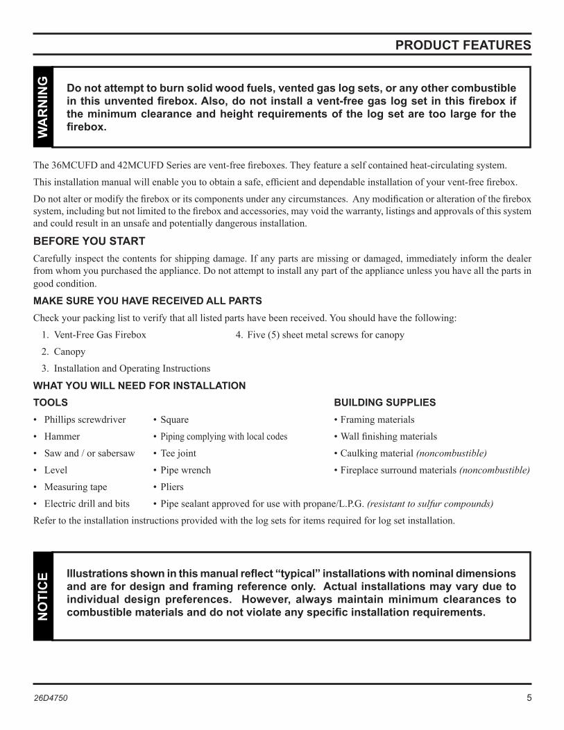
The36MCUFDand42MCUFDSeriesarevent-freefireboxes.Theyfeatureaselfcontainedheat-circulatingsystem.
Thisinstallationmanualwillenableyoutoobtainasafe,efficientanddependableinstallationofyourvent-freefirebox.
Donotalterormodifythefireboxoritscomponentsunderanycircumstances.Anymodificationoralterationofthefireboxsystem,includingbutnotlimitedtothefireboxandaccessories,mayvoidthewarranty,listingsandapprovalsofthissystemandcouldresultinanunsafeandpotentiallydangerousinstallation.
BEFORE YOU START Carefullyinspectthecontentsforshippingdamage.Ifanypartsaremissingordamaged,immediatelyinformthedealerfromwhomyoupurchasedtheappliance.Donotattempttoinstallanypartoftheapplianceunlessyouhaveallthepartsingoodcondition.
MAKE SURE yOU HAvE RECEIvED ALL pARtS Checkyourpackinglisttoverifythatalllistedpartshavebeenreceived.Youshouldhavethefollowing:
1. Vent-FreeGasFirebox 4. Five(5)sheetmetalscrewsforcanopy
2. Canopy
3. InstallationandOperatingInstructions
WHAT YOU WILL NEED FOR INSTALLATIONTOOLS BUILDING SUPPLIES • Phillipsscrewdriver • Square •Framingmaterials
• Hammer • Pipingcomplyingwithlocalcodes •Wallfinishingmaterials
• Sawand/orsabersaw • Teejoint •Caulkingmaterial(noncombustible)
• Level • Pipewrench •Fireplacesurroundmaterials(noncombustible)
• Measuringtape • Pliers
• Electricdrillandbits • Pipesealantapprovedforusewithpropane/L.P.G.(resistant to sulfur compounds)
Refertotheinstallationinstructionsprovidedwiththelogsetsforitemsrequiredforlogsetinstallation.
PRODUCT FEATURES
Do not attempt to burn solid wood fuels, vented gas log sets, or any other combustible in this unvented firebox. Also, do not install a vent-free gas log set in this firebox if the minimum clearance and height requirements of the log set are too large for the firebox. W
AR
NIN
G
Illustrations shown in this manual reflect “typical” installations with nominal dimensions and are for design and framing reference only. Actual installations may vary due to individual design preferences. However, always maintain minimum clearances to combustible materials and do not violate any specific installation requirements.N
OTI
CE

6 26D4750
Inplanningtheinstallationfortheapplianceitisnecessarytodeterminewheretheunitistobeinstalledandwhetheroptionalaccessoriesaredesired.Gassupplypipingshouldalsobeplanned.Thefollowingstepsrepresentthenormalsequenceofinstallation.Eachinstallationisunique,however,andmightrequireadifferentsequence.
1. Positionfireboxpriortoframingorintopreparedframing.
2. Fieldwiremainpowersupplytomodelswithfankit.(Electricalconnectionsshouldonlybeperformedbyanexperi-enced,licensed/certifiedtradesman).
3. Plumbgasline.(Gasconnectionsshouldonlybeperformedbyanexperienced,licensed/certifiedtradesman).
4. Installvent-freegaslogheaterpertheinstructionsprovidedwiththevent-freegaslogheater.
5. Completefinishwallmaterial,surroundandoptionalhearthextensiontoyourindividualtaste.
FIREBOX DIMENSIONS
GENERAL INSTALLATION INFORMATION
Figure 1 - Firebox Dimensions
DF
E
H
C
5.25"
32.125"
2.50" 2.50"
B 26.25"
9.75"
8.25"
37.375"
6"
36MCUFD 42MCUFD A 411/4" 47" B �6" 4�" C 181/4" 181/4" D ��" �8" E �0�/4" �0�/4" F �71/4" ��1/4"H ��7/8" �97/8"

26D4750 7
36MCUFD-F 36MCUFD-R 42MCUFD-F 42MCUFD-R
A �61/4" �5�/4" ��1/4" �1�/4" B 15" 14�/4" 15" 14�/4" C ��5/8" ��1/8" �85/8" �81/8" D �5" �5" �5" �5"E �01/�" �01/�" �01/�" �01/�"
MINIMUM HEARTH DIMENSIONS
GENERAL INSTALLATION INFORMATION and LOCATION OF FIREBOX
Figure 2 - Minimum Hearth Dimensions
LOCATION OF FIREBOX Carefullyselectthebestlocationforinstallationofyourvent-freefirebox.Thefollowingfactorsshouldbetakenintoconsideration:
• Clearance to side wall, ceiling, woodwork andwindows.See“Clearances/HeightRequirementsonpage8.Minimumclearancestocombustiblesmust be maintained.
• Locationmustnotbeaffectedbydraftscausedbykitchenexhaustfans,ceilingfans,returnairregistersforforcedairfurnaces/airconditioners,windowsordoors.
• Installationmustprovideadequateventilationandcombustionair.
• DO NOT INSTALL THIS FIREBOX IN A BEDROOM OR BATHROOM.
• Locationshouldbeoutofhightrafficorwindyordraftyareas.
• DO NOT INSTALL WHERE CURTAINS, FURNITURE, CLOTHING OR OTHER FLAMMABLE OBJECTS ARE LESS THAN 42" FROM FRONT OF HEATER.
• Neverobstructthefrontopeningofthevent-freefireboxorrestricttheflowofcombustionandventilationair.
• Minimizemodificationstoexistingconstruction.RefertoFigure3belowforlocationsuggestions.
• Donotinstallinthevicinitywheregasolineorotherflammableliquidsmaybestored.Thevent-freefireboxmustbekeptclearandfreefromthesecombustiblematerials.
Figure 3 - Location of Firebox

8 26D4750
6"Minimum
42"Minimum
6"Minimum
EnsurethatminimumclearancesshowninFigures4through7aremaintained.Leftandrightclearancesaredeterminedwhenfacingthefrontofthefirebox.
Followtheseinstructionscarefullytoensuresafeinstallation.Failuretofollowtheserequirementsmaycreateafirehazard.
1. Sidewall clearances: The clearance from the inside of theappliancetoanycombustiblewallshouldnotbelessthan6".See Figure 4.
2. Ceiling clearance: Theceilingmustbeatleast42”fromthetopofthefireboxopening.See Figure 4.
3. Back wall clearance:Theappliancemaybeplacedagainstacombustiblebackwall.
Figure 4 - Clearance and Height Requirements
4. Floor clearance: Thisinnerchamberfireboxfloormustbeinstalledatleast6"aboveanycombustibleflooringmate-rial,suchascarpetingorasphalttile,whichiscloserthan14"tothebaseofthefirebox.See Figure 5.
Or Theinnerchamberfireboxfloormaybeinstallednearertothefloorifaminimumof14"ofnoncombustiblematerial
suchasslateormarbleisinstalledbetweenthebaseofthefireboxandthecombustibleflooring. See Figure 6.
Figure 5 - Minimum Clearance above Combustible Flooring
Figure 6 - Minimum Clearance above Combustible Flooring with Non-Combustible Material Installed at
Base of Fireplace
CombustibleMaterial
6"Minimum14"Minimum
CanBeLessthan6" Non-Combustible
Material
CLEARANCES and HEIGHT REqUIREMENTS
26D4750 9
1�"
10"
8"
6"
�1/�"
1�"16"
19"�1"
��"
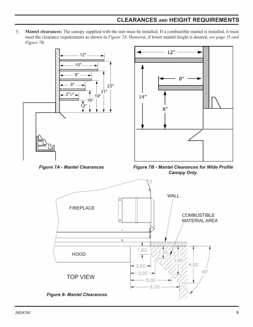
5. Mantel clearances: Thecanopysuppliedwiththeunitmustbeinstalled.Ifacombustiblemantelisinstalled,itmustmeettheclearancerequirementsasshowninFigure 7A.However,iflowermantelheightisdesired,see page 15 and Figure 7B.
Figure 7A - Mantel Clearances Figure 7B - Mantel Clearances for Wide Profile Canopy Only.
FIREPLACE
WALL
COMBUSTIBLEMATERIALAREA
HOOD
TOPVIEW
Figure 8- Mantel Clearances
CLEARANCES and HEIGHT REqUIREMENTS
10 26D4750
H
G
D
F
EA
C
B
A
81/4"
1/2"-5/8"
C
A
G
C
G
A½"-⅝"
FIREPLACE FRAMING
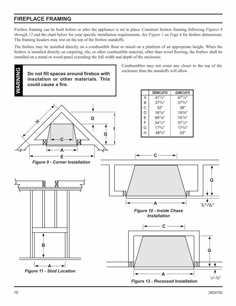
Fireboxframingcanbebuiltbeforeoraftertheapplianceissetinplace.ConstructfireboxframingfollowingFigures 9 through 12 andthechartbelowforyourspecificinstallationrequirements.See Figure 1 on Page 6 forfireboxdimensions.Theframingheadersmayrestonthetopofthefireboxstandoffs.
Thefireboxmaybeinstalleddirectlyonacombustiblefloororraisedonaplatformofanappropriateheight.Whenthefireboxisinstalleddirectlyoncarpeting,tile,orothercombustiblematerial,otherthanwoodflooring,thefireboxshallbeinstalledonametalorwoodpanelextendingthefullwidthanddepthoftheenclosure.
Figure 9 - Corner Installation
Figure 11 - Stud Location
Figure 10 - Inside Chase Installation
Figure 12 - Recessed Installation
Do not fill spaces around firebox with insulation or other materials. This could cause a fire.
WA
RN
ING
Combustibles may not come any closer to the top of theenclosurethanthestandoffswillallow.
36MCUFD 42MCUFDA 411/4" 471/4"B �7�/4" �7�/4"C ��" �8"D 16�/8" 19�/8"E 687/8" 747/8"F �41/�" �71/�"G 17�/4" 17�/4"H 48�/4" 5�"

26D4750 11
K
J
FIREPLACE FRAMING
36MCUFD MCUF42 with Trim with Trim
K 4�" 47�/4"J �81/8" �81/8"
1. Bendoutthenailingflangeslocatedoneachsideofthefirebox.
2. Slidethefireboxintopreparedframingorpositionfireboxinitsfinalpositionandframelater.
3. Levelthefireboxbycheckingthetopedgeofthefirebox.Shimifnecessary.
4. Anchorfireboxtothesideframingmembersusing8dnailsorothersuitablefasteners.See Figure 14.
5. Thecanopymustbeinstalledforsafeoperationoftheheater.See page 13forcanopyinstallationdetails.
Whenfinishingacustomcabinet,mantel,orotherbuilt-inenclosure,theopeningsizetoaccommodatethefireplacewithtriminstalledisasfollows:
Figure 13 - Custom Cabinet
Figure 14 - Location of Nailing Flanges
the fireplace must be installed giving full consideration to the clearance and height requirements identified in this manual.
WA
RN
ING
NailSidesThroughNailing
Flanges
1� 26D4750
GAS LINE INSTALLATION
Consultalllocalcodes.Allgaspipingmustbeinstalledtocomplywithlocalcodes,orintheabsenceoflocalcodes,withthelatesteditionoftheNationalFuelGasCodeANSIZ223.1/NFPA54.
Removethebaseplateforeaseofgaslineinstallation.Removethree(3)screwsalongthefrontedgeofthebaseplate.Removefour(4)screwswhichsecurethebaseplatetothecombustioncasing(twoatrearandonealongeachside).Replacebaseplatepriortoconnectinggaslinetoheater.Consultheaterinstallationandoperatinginstructionsforcorrectinstallationoftheheaterintothefirebox.
The1/2"gaslinemayentereitherfromtheleftsideorrightsideofthefirebox.Gasaccessholesareprovidedonbothsidesofthefirebox.
Alistedmanualshutoffvalvemustbeinstalledupstreamoftheappliance.Aunionteeandplugged1/8"NPTpressuretappingpointshouldbeinstalledupstreamofhteappliance.
IMPORTANT: Install main gas valve (equipment shutoff valve) in an accessible location. The main gas valve is for turning on or shutting off the gas to the fireplace.
Asedimenttrapmaybeupstreamoftheheatertopreventmoistureandcontaminantsfrompassingthroughtraptotheheatercontrolsandburners.Failuretodosocouldpreventtheheaterfromoperatingreliably.Consultapplicablecodes.
Anexternalregulatormustbeusedonallpropane/L.P.G.heaters,inadditiontotheregulatorfittedtotheheater,toreducethesupplytankpressureto13"w.c.(maximum).Anycoppertubingusedtosupplypropane/L.P.G.fromthetankmustbeinternallytinned.
Note: When connecting propane / L.P.G. vent-free room heaters, you must use pipe sealant resistant to propane / L.P.G.
Important: Hold heater regulator with a wrench to prevent movement when connecting to inlet piping.
Check gas type: the gas supply must be the same as stated on the heater’s rating plate. If the gas supply is different, DO NOT INSTALL THE HEATER. Contact your dealer for the correct model.
Aftercompletingconnection,testallgasjointsfromthegasmetertothegasheaterregulatorforleaks.Usingsoapandwatersolutionoragassniffer.DONOTUSEANOPENFLAME.
plumbing connections should only be performed by a qualified, licensed plumber. Main gas supply must be off when plumbing gas line to fireplace or performing service.
WA
RN
ING
Connecting directly to an unregulated propane / L.p.G. tank can cause an explosion.
WA
RN
ING
Do not connect directly to natural gas 1/2 PSI or 2 PSI systems. Always make sure natural gas pressure is regulated 10.5 w.c. (maximum before operating the unit).
WA
RN
ING

26D4750 1�
CANOPY INSTALLATION
INSTALLING CANOPY AcanopyisfurnishedwitheachfireboxandMUSTbeinstalledforsafeoperation.See Figure 15.
1.Removethethree(3)screwsfromthetopfrontframeassembly.Alsoremovethetwo(2)screwsonthesideframes.See Figure 15.
2.Alignthecanopywiththeholesinthetopframe.
3.Replacethescrewspreviouslyremoved.
4.Tightensidescrews.Makesurethecanopyislevelandsecure.
the firebox canopy must not be modified or replaced with a canopy that may be provided with the unvented decorative room heater.
WA
RN
ING
Close fireplace screen panel before operating a decorative type unvented room heater.
WA
RN
ING
Figure 15 - Installing Canopy

14 26D4750
ThermostatControl
Fan Switch
OFF
ONBlackWhiteGreen
110/115V.A.C.
Black
BlowerMotor
OPTIONAL EqUIPMENT
FORCED AIR KIt (BLOTMC)Ifyouareinstallingtheforcedairkit,ModelBLOTMC,on36MCUFDor42MCUFDmodels,seetheinstallationinstructionsprovidedwiththekitforelectricalwiringrequirements,ortheblowerinstallationsection.Thefireboxmustbeconnectedtomainpowersupplyattimeoffireboxinstallation.Theblowermustbeinstalledpriortotheinstallationofthevent-freeheater.Theelectricalconnectionsmustbemadebeforethefireboxisframedandenclosedinthefinishedwalls.
Electrical connections should only be performed by a qualified, licensed electrician, main power must be off when connecting to main electrical power supply or performing service.the blower when installed, must be electrically grounded in accordance with local codes or in the absence of local codes, with the National Electrical Code ANSI Z.223.1/NFPA 70.W
AR
NIN
G
Anyoftheoriginalwireassuppliedwiththefireplacemustbereplaced.Contactdealer forproperreplacementwiringharness.(see parts list for part number).120volts,60Hz,1amps.
Electrical power cord (plug) can be routed to exit the36MCUFD/42MCUFDoneithertheleftsideortherightside.Removecordprotectorfromsideofunit,routepowercordthroughholeoppositeside.Reinstallcordprotector.
this fireplace has a three-prong, grounded electrical plug. this plug helps protect you against electrical shock. Only connect plug to a properly grounded, three-prong receptacle. Do not cut or remove the grounded prong from this plug.
WA
RN
ING
Never attempt to service heater while it is plugged in, operating, or hot. Burns and/or electrical shock could result.
WA
RN
ING
Figure 16 - BLOTMC Wiring Diagram
IMPORTANT: Always check local building codes. The installation must comply with local regulations as well as the national electric codes.
BRASS OR CHROME TRIMOptionalbrasstrimkitscanbeusedwithunitwheninstalledasafreestandingfireplacewithwoodsurround.
OPTIONAL WIDE CANOPY Theoptionalwidecanopycanbeinstalled.Seeinstallationinstructionsprovidedwithkit.

26D4750 15
1
4
5Ê
2
3
*Not illustrated, see following page.
ILLUSTRATED PARTS LIST
ITEM DESCRIPTION qTY 36MCUFD 42MCUFD
1 Canopy 1 71D0500 71D1000 � ScreenPanel � �6D456� �6D456�� � ScreenRod � �6D01��K �6D01��K
ACCESSORIES IN KItS
1 StandardBrassCanopy 1 BRCU�6 BRCU4� 1 WideBrassCanopy 1 BRC�6 BRC4� 4 Blowerw/Rheostat 1 BLOTMC BLOTMC 5 BrassTrimCurvedDesign 1 BRTKM�6 BRTKM4� 5 PewterTrimCurvedDesign 1 PWTKM�6 PWTKM4� 5 BlackTrimCurvedDesign 1 BLTKM�6 BLTKM4� 6 OutsideAirKit* 1 AK-4 AK-4

16 26D4750
USING OptIONAL AK-4 OUtSIDE AIR KIt
8'max.
COMBUSTION AIR 1. Locatecombustionairassemblyatanexteriorlocationwhichisnotlikelytobeaccidentallyblockedinanymanner.
Locateassemblyamin.of12"abovethesnowlinetopreventblockagebysnowaccumulation.
2. Nevermountthecombustionairinletassemblyinagarageorstorageareawherecombustiblefumessuchasgasolinemightbedrawnintothefireplace.
3. Combustionaircanbedrawnfromthecrawlspaceunderahousewhenanadequatesupplyofairisprovidedbyopenventilation.
4. CAUTION: Do not take combustion air from attic space or garage space.
5.Locateairsupplyinletatleast3'awayfromanyapplainceventterminal.
6. Avoidextremelylongrunsandnumerousturnsintheductleadingfromthefireplacetothecombustionairassembly.Theseconditionsincreasetheresistancetothefreeflowofairthroughtheduct.See Figures 17 through 20 formethodsofinstallingtheoutsideairforcombustionassemblies.
Figure 17 - Basement Installation Figure 18 - Concrete Slab Installation
(Optional Outside Air Runs)
AboveSnowLevel
GroundLevel
BasementWall
FirestopSpacer
InletGrillinSoffit
(Overhang)
Figure 20 - 45° Corner Installation on Slab Floor
Figure 19 - Installation Above Basement or Crawl Space
InsideWall
OutsideWall
DuctExtendedtoMissJoist
ToOutsideWall
Note: Fireplace model in illustrations may not be representative of your appliance.
26D4750 17
USING OptIONAL AK-4 OUtSIDE AIR KIt
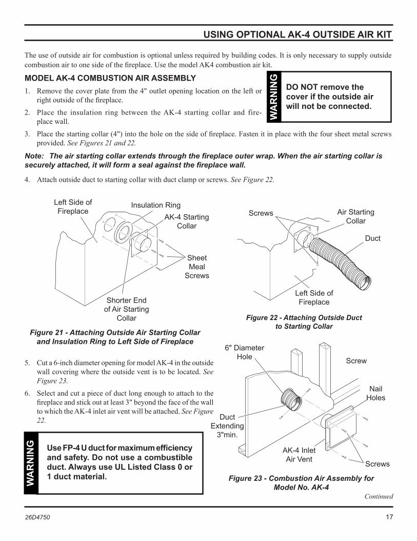
Theuseofoutsideairforcombustionisoptionalunlessrequiredbybuildingcodes.Itisonlynecessarytosupplyoutsidecombustionairtoonesideofthefireplace.UsethemodelAK4combustionairkit.
MODEL AK-4 COMBUStION AIR ASSEMBLy1. Removethecoverplatefromthe4"outletopeninglocationontheleftor
rightoutsideofthefireplace.
2. Place the insulation ring between theAK-4 starting collar and fire-placewall.
3. Placethestartingcollar(4")intotheholeonthesideoffireplace.Fastenitinplacewiththefoursheetmetalscrewsprovided.See Figures 21 and 22.
Note: The air starting collar extends through the fireplace outer wrap. When the air starting collar is securely attached, it will form a seal against the fireplace wall.
4. Attachoutsideducttostartingcollarwithductclamporscrews.See Figure 22.
DO NOT remove the cover if the outside air will not be connected.
WA
RN
ING
Figure 21 - Attaching Outside Air Starting Collar and Insulation Ring to Left Side of Fireplace
Figure 22 - Attaching Outside Duct to Starting Collar
InsulationRingAK-4Starting
Collar
SheetMeal
Screws
LeftSideofFireplace
ShorterEndofAirStarting
Collar
AirStartingCollar
Duct
Screws
LeftSideofFireplace
5. Cuta6-inchdiameteropeningformodelAK-4intheoutsidewallcoveringwheretheoutsideventistobelocated.See Figure 23.
6. Selectandcutapieceofductlongenoughtoattachtothefireplaceandstickoutatleast3"beyondthefaceofthewalltowhichtheAK-4inletairventwillbeattached.See Figure 22.
Figure 23 - Combustion Air Assembly for Model No. AK-4
NailHoles
Use Fp-4 U duct for maximum efficiency and safety. Do not use a combustible duct. Always use UL Listed Class 0 or 1 duct material.
WA
RN
ING
6"DiameterHole
DuctExtending
�"min.
AK-4InletAirVent
Screw
Screws
Continued

18 26D4750
MODEL AK-4 COMBUStION AIR ASSEMBLy (CONTINueD)
7. Iftheductistheinsulatedtype,pushtheinsulationbackfromoneendoftheductapproximately2".See Figure 24.
8. Sliptheexposedendoftheductoverthestartingcollaronthefireplace.
9. Usingthesheetmetalscrewsprovided,securetheductendtothecollarattachedtothefireplace.
10. Nailorscrewthecombustionairassemblytothesurfaceofthewall.
Note: If the wall covering is brick or stone, use appropriate masonry fasteners. If necessary, splice the duct. use a model 403-duct connector to splice duct sections.
INSTALLING MODEL 403 DUCT CONNECTOR1. Pushinsulationbackapproximately2"fromtheendofeachduct.
2. Slipeachductoverductconnectoruntilanequallengthofconnectorextendsintoeachduct.
3. Placeductclampovertheendofeachduct.Tightenductclampdownsnuggly.
4. Pushinsulationbackintoplaceandoverductclamp.
Figure 24 - Installing Duct Connector 403
Approximately�"
Insulation
DuctConnector
DuctClamp
USING OptIONAL AK-4 OUtSIDE AIR KIt
26D4750 19
LIMITED LIFETIME WARRANTY POLICY
Thefollowingcomponentsarewarrantedforlifetotheoriginalowner,subjectofproofofpurchase:Firebox,CombustionChamber,HeatExchanger,Grate,andStainlessSteelBurners.
FIVE YEAR WARRANTYThefollowingcomponentsarewarrantedfor5yearstotheoriginalowner,subjectofproofofpurchase:VentFreeCeramicFiberLogs,CatalyticFilterandAluminizedBurners.
BASIC WARRANTYMHSCwarrantsthecomponentsandmaterialsinyourgasappliancetobefreefrommanufacturingandmaterialdefectsforaperiodoftwoyearsfromdateofinstallation.Afterinstallation,ifanyofthecomponentsmanufacturedbyMHSCintheappliancearefoundtobedefectiveinmaterialsorworkmanship,MHSCwill,atitsoption,replaceorrepairthedefectivecomponentsatnochargetotheoriginalowner.MHSCwillalsopayforreasonablelaborcostsincurredinreplacingorrepairingsuchcomponentsforaperiodoftwoyearsfromthedateofinstallation.Anyproductspresentedforwarrantyrepairmustbeaccompaniedbyadatedproofofpurchase.
ThisLimitedLifetimeWarrantywillbevoidiftheapplianceisnotinstalledbyaqualifiedinstallerinaccordancewiththeinstallationinstructions.TheLimitedLifetimeWarrantywillalsobevoidiftheapplianceisnotoperatedandmaintainedaccordingtotheoperatinginstructionssuppliedwiththeappliance,anddoesnotextendto(1)firebox/burnerassemblydamagebyaccident,neglect,misuse,abuse,alteration,negligenceofothers,includingtheinstallationthereofbyunqualifiedinstallers,(2)thecostsofremoval,reinstallationortransportationofdefec-tivepartsontheappliance,or(3)incidentalorconsequentialdamage.Allserviceworkmustbeperformedbyanauthorizedservicerepresentative.
Thiswarrantyisexpresslyinlieuofotherwarranties,expressorimplied,includingthewarrantyofmerchantabilityoffitnessforpurposeandofallotherobligationsorliabilities.MHSCdoesnotassumeforitanyotherobligationsorliabilityinconnectionwiththesaleoruseoftheappliance.Instatesthatdonotallowlimitationsonhowlonganimpliedwarrantylasts,ordonotallowexclusionofindirectdamage,thoselimitationsofexclusionsmaynotapplytoyou.YoumayalsohaveadditionalrightsnotcoveredinthisLimitedLifetimeWarranty.
MHSCreservestherighttoinvestigateanyandallclaimsagainsttheLimitedLifetimeWarrantyanddecideuponmethodofsettlement.
IF WARRANTY SERVICE IS NEEDED...1. Contactyoursupplier.Makesureyouhaveyourwarranty,yoursalesreceiptandthemodel/serialnumberof
yourMHSCproduct.2. DONOTATTEMPTTODOANYSERVICEWORKYOURSELF.

AUGUST 200826D4750 • Rev. 9
MHSC149ClevelandDrive•Paris,Kentucky40�61
www.mhsc.com