magnetoresistive high temperature bearingless encoderthe northstar endurance56 is a modular digital...
TRANSCRIPT
Instruction ManualENDURANCE 56
Magnetoresistive High Temperature Bearingless Encoder
702820-0002 REV. -
brandNorthStar TM
PatentPending
©DYNAPAR +1.800.873.8731 702820-0002 Rev. - February 2010
NorthStar ENDURANCE 56 Instruction Manual
Page 2
©DYNAPAR +1.800.873.8731 702820-0002 Rev. - February 2010
NorthStar ENDURANCE 56 Instruction Manual
Page 3
Table of Contents
Chapter/Paragraph/Illustration Page
1 Introduction .................................................................................................. 4
1.0 Safety Summary ............................................................................................. 4
1.1 General ........................................................................................................... 5
1.2 Description ..................................................................................................... 5
Figure 1: Endurance56 Exploded View w/ Spare Parts ................................. 5
1.3 Specifications. ................................................................................................ 6
2 Installation. .................................................................................................. 7
2.0 Inspection and Unpacking .............................................................................. 7
2.1 Motor Facing and Shaft .................................................................................. 7
Figure 2: Typical 4.5-Inch Diameter Type C-Face Mounting Surface ............. 7
2.2 Encoder Frame Installation ............................................................................ 8
Figure 3: Typical Motor Mounting ................................................................... 8
Figure 3a: Hub Alignment with Spacer ........................................................... 8
Figure 4: Pulse Wheel Orientation ................................................................. 9
2.3 Electrical Installation ....................................................................................... 10
2.4 Returning NorthStar brand Equipment to Dynapar ....................................... 11
2.5 Ordering Information ...................................................................................... 12
Methods and apparatus disclosed and described herein have been developed solely oncompany funds of Dynapar. No government or other contractual support or relationshipwhatsoever has existed which in any way affects or mitigates proprietary rights of Dynaparin these developments. Methods and apparatus disclosed herein may be subject to U.S.Patents existing or applied for. Dynapar reserves the right to add, improve, modify, or with-draw functions, design modifications, or products at any time without notice. Dynapar shallnot be liable for errors contained herein or for incidental or consequential damages inconnection with furnishing, performance, or use of this material.
©DYNAPAR +1.800.873.8731 702820-0002 Rev. - February 2010
NorthStar ENDURANCE 56 Instruction Manual
Page 4
CHAPTER 1
INTRODUCTION
1.0 Safety SummaryHigh current, voltage, and rotating parts can cause serious or fatal injury. The use of electric machinery,like all other uses of concentrated power and rotating equipment, may be hazardous. Installing, operating,and maintaining electric machinery should be performed by qualified personnel, in accordance withapplicable provisions of the National Electrical Code and sound local practices. Failure to comply withthese precautions or with specific warnings elsewhere in this manual violates safety standards of design,manufacture, and intended use of the instrument. Dynapar assumes no liability for the customer's failureto comply with these requirements.
Rotating MachineryAvoid contact with rotating parts. Avoid by-passing or rendering inoperative any safety guards or protec-tion devices. Avoid extended exposure in close proximity to machinery with high noise levels. Use propercare and procedures in handling, lifting, installing, operating and maintaining the equipment.
Before InstallationSafe maintenance practices with qualified personnel is imperative. Before starting maintenance proce-dures, be positive that, (1) equipment connected to the shaft will not cause mechanical rotation, (2) mainmachine windings have been disconnected and secured from all electrical power sources, and (3) allaccessory devices associates with the work area have been de-energized. If high potential insulation testis required, follow procedures and precautions outlined in NEMA standards MG-1.
GroundingImproperly grounding the frame of the machine can cause serious or fatal injury to personnel. Groundingof the machine frame and structure should comply with the National Electrical Code and with sound localpractices. Check wiring diagram before connecting power.
Do Not Operate In An Explosive AtmosphereDo not operate the instrument in the presence of flammable gases or fumes. Operating any electricalinstrument in such an environment constitutes a definite safety hazard.
Keep Away From Live CircuitsOperating personnel must not remove instrument covers. Component replacement and internal adjustmentsmust be made by qualified maintenance personnel. Do not replace components with power cable connected.To avoid injuries, always disconnect power and discharge circuits before touching them.
Do Not Substitute Parts Or Modify InstrumentDo not install substitute parts or perform any unauthorized modification to the instrument. Introducingadditional hazards is dangerous. Return the instrument to an authorized Dynapar representative for serviceand repair to ensure that safety features are maintained.
Dangerous Procedure CautionsA CAUTION heading precedes potentially dangerous procedures throughout this manual. Instructions in thewarnings must be followed.
©DYNAPAR +1.800.873.8731 702820-0002 Rev. - February 2010
NorthStar ENDURANCE 56 Instruction Manual
Page 5
1.1 GeneralThese instructions do not claim to cover all details of variation in equipment or to provide for every possible
contingency or hazard to be met in connection with installation, operation, and service. Should furtherinformation be desired or should particular problems arise which are not covered sufficiently for thepurchaser’s purposes, please contact Dynapar., or one of its designated representatives.
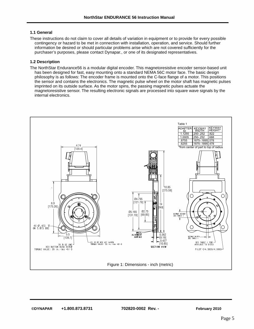
1.2 DescriptionThe NorthStar Endurance56 is a modular digital encoder. This magnetoresistive encoder sensor-based unit
has been designed for fast, easy mounting onto a standard NEMA 56C motor face. The basic designphilosophy is as follows: The encoder frame is mounted onto the C-face flange of a motor. This positionsthe sensor and contains the electronics. The magnetic pulse wheel on the motor shaft has magnetic pulsesimprinted on its outside surface. As the motor spins, the passing magnetic pulses actuate themagnetoresistive sensor. The resulting electronic signals are processed into square wave signals by theinternal electronics.
Figure 1: Dimensions - inch (metric)
4.74[120.4]
6.9[175.26]
5.5[139.7]
Ø5.165[131.19]
Ø4.795[121.79]
Ø2.75[69.85]
0.362[9.19]0.427
[10.85]
10.85[275.59]
7.64[194.06]
1.1255 .250-.252 .822
1.0005 .250-.252 .688.8755 .1875-.1895 .578.6255 .1875-.1895 .478
ADAPTER ID WIDTH
KEYWAY HEIGHT*
*from center of part to top of radius
KEYWAY
Table 1
©DYNAPAR +1.800.873.8731 702820-0002 Rev. - February 2010
NorthStar ENDURANCE 56 Instruction Manual
Page 6
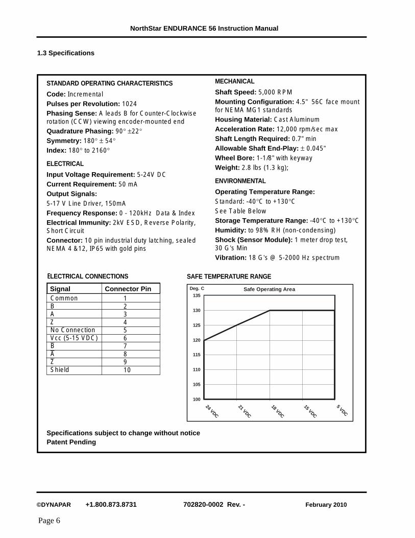
1.3 Specifications
STANDARD OPERATING CHARACTERISTICS
Code: IncrementalPulses per Revolution: 1024Phasing Sense: A leads B for Counter-Clockwiserotation (CCW) viewing encoder-mounted endQuadrature Phasing: 90° ±22°Symmetry: 180° ± 54°Index: 180° to 2160°
ELECTRICAL
Input Voltage Requirement: 5-24V DCCurrent Requirement: 50 mAOutput Signals:5-17 V Line Driver, 150mAFrequency Response: 0 - 120kHz Data & IndexElectrical Immunity: 2kV ESD, Reverse Polarity,Short CircuitConnector: 10 pin industrial duty latching, sealedNEMA 4 &12, IP65 with gold pins
ELECTRICAL CONNECTIONS
MECHANICAL
Shaft Speed: 5,000 RPMMounting Configuration: 4.5” 56C face mountfor NEMA MG1 standardsHousing Material: Cast AluminumAcceleration Rate: 12,000 rpm/sec maxShaft Length Required: 0.7” minAllowable Shaft End-Play: ± 0.045”Wheel Bore: 1-1/8” with keywayWeight: 2.8 lbs (1.3 kg);
ENVIRONMENTAL
Operating Temperature Range:Standard: -40°C to +130°CSee Table BelowStorage Temperature Range: -40°C to +130°CHumidity: to 98% RH (non-condensing)Shock (Sensor Module): 1 meter drop test,30 G’s MinVibration: 18 G’s @ 5-2000 Hz spectrum
100
105
110
115
120
125
130
135
24 VDC
21 VDC
18 VDC
15 VDC
5 VDC
Safe Operating AreaDeg. C
SAFE TEMPERATURE RANGE
Specifications subject to change without notice
CommonBAZNo ConnectionVcc (5-15 VDC)—B—A—ZShield
12345678910
Signal Connector Pin
Patent Pending
©DYNAPAR +1.800.873.8731 702820-0002 Rev. - February 2010
NorthStar ENDURANCE 56 Instruction Manual
Page 7
2.0 Inspection and UnpackingInspect shipping container for external damage. All claims for damage (apparent or concealed) or partial lossof shipment must be made in writing to Dynapar within (5) days from receipt of goods. If damage or loss isapparent, please notify the shipping agent immediately.
Open shipping container and locate the packing list. The packing list is included to verify that all components,accessories, and manual were received. Please use the packing list to check off each item as the unit isunpacked. Inspect for damage. We recommend that the shipping container be retained for future shipping,storage, or return to factory purposes.
If any equipment was damaged in transit, be sure to file proper claims promptly with the carrier and insurancecompany. Please advise us of such filing. In case of parts shortages, advise us immediately. Dynapar cannotbe responsible for any missing parts unless notified within 60 days of shipment.
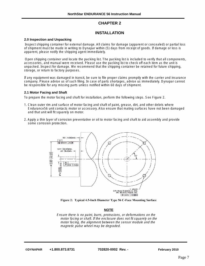
2.1 Motor Facing and ShaftTo prepare the motor facing and shaft for installation, perform the following steps. See Figure 2.
1. Clean outer rim and surface of motor facing and shaft of paint, grease, dirt, and other debris whereEndurance56 unit contacts motor or accessory. Also ensure that mating surfaces have not been damagedand that unit will fit squarely on motor.
2. Apply a thin layer of corrosion preventative or oil to motor facing and shaft to aid assembly and providesome corrosion protection.
CHAPTER 2
INSTALLATION
NOTEEnsure there is no paint, burrs, protrusions, or deformations on the
motor facing or shaft. If the enclosure does not fit squarely on themotor facing, the alignment between the sensor module and themagnetic pulse wheel may be degraded.

©DYNAPAR +1.800.873.8731 702820-0002 Rev. - February 2010
NorthStar ENDURANCE 56 Instruction Manual
Page 8
2.2 To install the encoder frame, perform the following steps:
NOTES:1. The encoder and the wheel are a matched set and are not interchangeable. The serial numbers should be
double checked to ensure proper assembly and performance. The serial number on the encoder is foundon the encapsulation (example: 102). The serial number on the wheel is found on the front of the wheel(example: 102W).
2. The ENDURANCE 56 wheel consists of two parts:A. The hub (secured to the shaft).B. The pulse wheel (secured to the hub).
1) Install Encoder: Position the encoder frame so the 4.5 inch I.D. surface will fit over the 4.5 inch C flange(encapsulated side toward the motor). Mount frame onto the motor flange. Insert the four 3/8 inch x 16 UNCsocket head cap screws through the frame and into the motor frame. Use a 5/16 inch hex wrench to tighten anominal 25 foot pounds. See Figure 3.
2) Install Hub: Position the hub so that the large flange faces the motor. Slide the hub on the motor shaft.Using the installation tool, align the front of the installation tool and the front of the hub so they are flush witheach other. See Figure 3a. The hub in now properly aligned. Apply Loctite 222 to the two 10-32 UNC setscrews. Making sure the hub is firmly seated flush with the alignment tool, use a 3/32 inch hex wrench totighten the screws to a nominal 25 in-lbs.
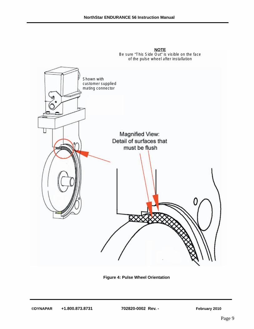
3) Install the Pulse Wheel: Position the pulse wheel so the label, “This Side Out” is visible. Slide it onto theshaft until it makes contact with the hub. Rotate the pulse wheel so the pin in the hub goes through the pinhole in the pulse wheel. It may also be helpful to use two 1/4-20 UNC screws lightly threaded into the pulsewheel to help position the pulse wheel. The three mounting holes are now aligned. Apply Loctite 222 to thethree 8-32 UNC button head screws. Use a 3/32 inch hex wrench to tighten the screws into the pulse wheelto a nominal 20 in-lbs. Remove the two 1/4-20 UNC screws from the pulse wheel.
Figure 3a: Hub alignment withinstallation spacerFigure 3: Typical Motor Mounting
HUB
ENCODER
PULSE WHEEL
HUB
SURFACES MUST BE FLUSH
INSTALLATION TOOL
©DYNAPAR +1.800.873.8731 702820-0002 Rev. - February 2010
NorthStar ENDURANCE 56 Instruction Manual
Page 9
Shown withcustomer suppliedmating connector
NOTEBe sure “This Side Out” is visible on the face
of the pulse wheel after installation
Figure 4: Pulse Wheel Orientation

©DYNAPAR +1.800.873.8731 702820-0002 Rev. - February 2010
NorthStar ENDURANCE 56 Instruction Manual
Page 10
2.3 Electrical InstallationElectrical connections are made to the sensor module through a standard 1/2 inch NPT liquid tight flexibleconduit. The nipple length may be changed to extend the outlet box if desired. Interconnection cable recom-mendations are as follows: stranded copper, 22 through 16 gage, braided or foil with drain wire shielding0.05 µF maximum total mutual or direct capacitance, outer sheath insulated. Shrink tubing may be placedover any wires without insulation. For lengths over 100 feet, use 18 gage or larger, to a maximum of 1000feet. If shielded twisted pair wire is used, do not cross channels. Keep each pair of complementary channeloutputs together in a single twisted pair (e.g., A and A complement).
Signal
Common
B
A
Z *
No Connection
Vcc (5-15 VDC)
/B
/A
/Z *
Shield
Connector Pin
1
2
3
4
5
6
7
8
9
10
NOTEThe shield in the sensor module is isolated from the frame of theencoder for maximum noise immunity. The shield wire or pin shouldbe connected to the shield of the cable and that of the drive or otherreceiving device.
Table 1. Signal Coding Table
CAUTION!Reversing power and common will not damage the unit.However, applying power to any of the sensor outputsmay cause damage.
©DYNAPAR +1.800.873.8731 702820-0002 Rev. - February 2010
NorthStar ENDURANCE 56 Instruction Manual
Page 11
2.4 Returning Equipment to DynaparIf it is necessary to return the unit for repair or replacement, a Return Material Authorization (RMA) numbermust be obtained from a factory representative before returning the equipment to our service department.When returning an instrument for service, the following information must be provided before we can attemptany repair.
1. Instrument model and serial number
2. User’s name, company, address, and phone number
3. Malfunction symptoms
4. Description of system
5. Returned Goods Authorization number
Consult the factory for shipping instructions.
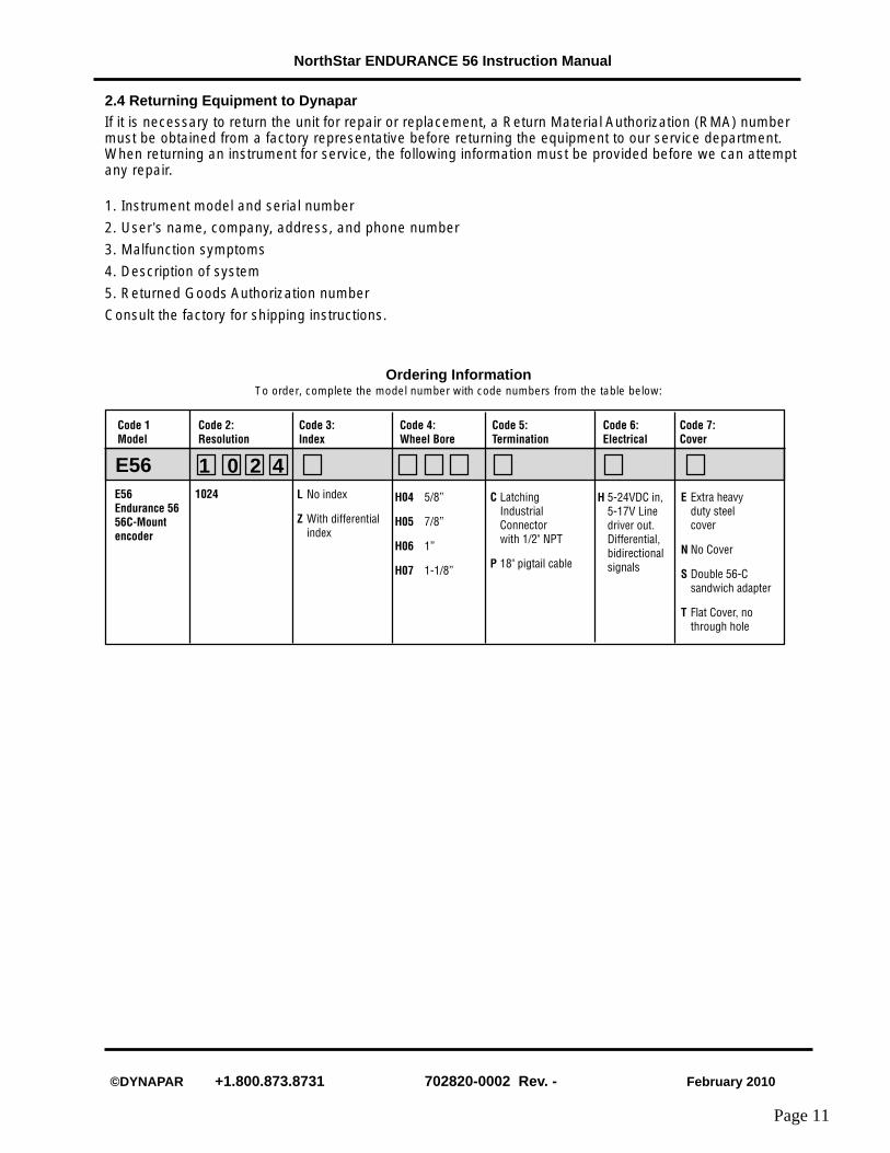
Ordering InformationTo order, complete the model number with code numbers from the table below:
E56Endurance 5656C-Mountencoder
Code 1Model
Code 2:Resolution
E56 1 0 2 4
Code 3:Index
L No index
Z With differentialindex
1024
Code 4:Wheel Bore
H04 5/8”
H05 7/8”
H06 1”
H07 1-1/8”
Code 5:Termination
C LatchingIndustrialConnectorwith 1/2" NPT
P 18" pigtail cable
Code 6:Electrical
H 5-24VDC in,5-17V Linedriver out.Differential,bidirectionalsignals
Code 7:Cover
E Extra heavyduty steelcover
N No Cover
S Double 56-Csandwich adapter
T Flat Cover, nothrough hole
©DYNAPAR +1.800.873.8731 702820-0002 Rev. - February 2010
NorthStar ENDURANCE 56 Instruction Manual
Page 12