magnetism and spin transport in rare-earth-rich epitaxial...
TRANSCRIPT

PHYSICAL REVIEW MATERIALS 2, 094405 (2018)
Magnetism and spin transport in rare-earth-rich epitaxial terbium and europium iron garnet films
Ethan R. Rosenberg,1 Lukáš Beran,1,2 Can O. Avci,1 Cyrus Zeledon,1,3 Bingqian Song,1 Claudio Gonzalez-Fuentes,4
Johannes Mendil,5 Pietro Gambardella,5 Martin Veis,2 Carlos Garcia,4 Geoffrey S. D. Beach,1 and Caroline A. Ross1
1Department of Materials Science and Engineering, Massachusetts Institute of Technology, Cambridge, Massachusetts 02139, USA2Faculty of Mathematics and Physics, Charles University, Ke Karlovu 3, 12116 Prague 2, Czech Republic
3Department of Materials Science and Engineering, Cornell University, Ithaca, New York 14850, USA4Departament of Physics, Universidad Técnica Federico Santa María, Avenida España 1680, 2390123 Valparaíso, Chile
5Department of Materials, ETH Zürich, CH-8093 Zürich, Switzerland
(Received 13 April 2018; revised manuscript received 17 July 2018; published 14 September 2018)
Rare-earth iron garnet thin films with perpendicular magnetic anisotropy (PMA) have recently attracted agreat deal of attention for spintronic applications. Thulium iron garnet (TmIG) has been successfully grown andTmIG/Pt heterostructures have been characterized. However, TmIG is not the only rare-earth iron garnet thatcan be grown with PMA. We report the growth, magnetic, and spintronic properties of epitaxial terbium irongarnet (TbIG) and europium iron garnet (EuIG) thin films with PMA. Reciprocal space mapping shows the filmsare lattice matched to the substrate without strain relaxation, even for films up to 56 nm thick. The lattice strainand magnetostriction coefficient produce PMA in certain cases. TbIG grows on (111) gadolinium gallium garnet(GGG) with PMA due to the in-plane compressive strain, whereas TbIG on (111) substituted GGG (SGGG) isin tension and has an in-plane easy axis. EuIG grows with PMA on (100) and (111) GGG substrates, whichfacilitates the investigation of spintronic properties as a function of orientation. Both garnets have excess rareearth, which is believed to occupy Fe octahedral sites and in the case of TbIG is associated with an increase in thecompensation temperature to 330 K, higher than the bulk value. Anomalous Hall effect (AHE) measurementsof Pt/EuIG Hall crosses show that the spin mixing conductance of Pt/ (111) and (100) EuIG is similar. AHEmeasurements of Pt/TbIG Hall crosses reveal a sign change in the AHE amplitude at the compensation pointanalogous to all-metallic systems.
DOI: 10.1103/PhysRevMaterials.2.094405
I. INTRODUCTION
Spin transport across heavy metal/ferrimagnetic insulator(HM/FMI) interfaces has attracted a great deal of interest overthe past decade. Magnon-mediated spin currents in Y3Fe5O12
(YIG) were observed by the inverse spin Hall effect in aPt overlayer [1,2], and conversely a spin-orbit torque (SOT)produced by the Pt layer was used for the propagation andsubsequent detection of magnons in YIG [1,3]. These resultssuggested the possible manipulation of the magnetization ofinsulating materials with an electric current. SOT-assistedreversal was reported in barium hexaferrite [4], but the firstreported switching of a HM/FMI structure by SOT utilizedTm3Fe5O12 (TmIG or thulium iron garnet) as the FMI layer[5]. Electrical switching of magnetization has applications inSOT-magnetic random access memory and other emergingmemory technologies. Materials with perpendicular magneticanisotropy (PMA) are desirable for such devices because theyallow for higher bit densities [6,7]. There has been extensivework on SOT switching of PMA ferromagnetic metals suchas Co and CoFeB [8–11], but FMIs have two advantagesover metals: a more favorable scaling behavior, because thePMA originates from bulk rather than interface anisotropy;and prevention of current shunting from the SOT-producingHM layer [4].
The best studied FMI is YIG, which is a good insu-lator with exceptionally low damping, as well as a low
magnetostriction and magnetocrystalline anisotropy. YIGfilms typically exhibit an in-plane easy axis dominated byshape anisotropy, although there are reports of thin YIGfilms showing PMA [12–14]. Other FMI films have beengrown with PMA, notably barium hexaferrite (BaFe12O19,BaM) grown epitaxially on sapphire with anisotropy field of17 kOe [4,15]; and Co ferrite (CoFe2O4) grown epitaxiallyon substrates such as SrTiO3 or MgO [16,17]. Rare-earth irongarnets (REIG) with PMA have also been developed, in whichthe PMA originates from magnetoelastic anisotropy due tothe epitaxial mismatch strain of the REIG on the gadoliniumiron garnet (GGG) substrate [12,18]. TmIG [5,18,19], SmIG(Sm3Fe5O12) [20], and TbIG (Tb3Fe5O12) [21] films, as wellas Ce- or Bi-substituted YIG [22–24], exhibit strain-inducedPMA. Other thin film RE garnets include GdIG (Gd3Fe5O12)[25] and LuIG (Lu3Fe5O12) [26] with in plane easy axis. Outof the PMA RE garnets, TmIG is the most extensively studiedin terms of the spintronic properties of the FMI/HM interface[19,27–30]. TmIG/HM devices exhibited SOT-driven reversalwith applied fields as low as 2 Oe and evidence of fastcurrent-induced domain wall velocities reaching 1000 m/s ata current density of 2.5 × 10¹² A/m2 in the Pt [28]. TmIG/Ptheterostructures were also recently used to study the validityof the bulk spin Hall effect model for SOT [29].
In this paper, we describe the growth, structure, and themagnetic and spintronic properties of two rare-earth irongarnets: TbIG and EuIG (Eu3Fe5O12). These materials were
2475-9953/2018/2(9)/094405(8) 094405-1 ©2018 American Physical Society

ETHAN R. ROSENBERG et al. PHYSICAL REVIEW MATERIALS 2, 094405 (2018)
FIG. 1. [(a)–(d)] High-resolution XRD ω-2θ scans of representative EuIG and TbIG thin films [(e) and (f)] High-resolution XRD reciprocalspace maps of TbIG/GGG and TbIG/SGGG thin films.
selected based on their bulk magnetostriction values andtheir lattice mismatch with respect to GGG, which lead toa magnetoelastic anisotropy contribution that determines thenet anisotropy of the film [31,32]. For TbIG and TmIG, thetwo magnetostriction coefficients λ111 and λ100 have oppositesign and PMA is expected in films grown epitaxially on(111) GGG but not on (001) GGG [31]. In contrast, the twomagnetostriction coefficients of EuIG are of the same signand EuIG/GGG is expected to exhibit PMA in both the (111)and (001) orientations. EuIG and TbIG were grown by pulsedlaser deposition and the composition is enriched in RE com-pared with the target. We demonstrate efficient spin transportthrough Pt/TbIG and Pt/EuIG interfaces through anomalousHall effect-like spin Hall magnetoresistance (AHE-like SMR)measurements and show that the spin-mixing conductance ofPt/EuIG is approximately orientation-independent, in contrastto what has been observed in Pt/cobalt ferrite heterostructures[16]. We demonstrate by magnetometry, magnetoresistance,and optical measurements the presence of a compensationtemperature [31] near room temperature in TbIG, and reportthe damping coefficient of the EuIG (111) films.
II. STRUCTURAL AND MAGNETIC CHARACTERIZATION
EuIG and TbIG thin films of thicknesses varying from 10 to90 nm were grown on GGG (lattice parameter a = 1.2376 A)and substituted GGG (SGGG, a = 1.2497 A) using pulsedlaser deposition (PLD) in an oxygen pressure of 150 mTorr.In all cases, the substrate was placed on a sample holderheated to a backside temperature of 900 ˚C. The frontside(substrate) temperature was not measured directly but was∼250 ˚C lower. The targets used in these depositions wereprepared by sintering [19]. Further information on the filmand target preparation is presented in the Methods section.
The high crystalline quality of these films is evident fromthe Laue fringes present in each symmetric (444) scan inFigs. 1(a)–1(d), which were taken from representative thinfilms of each type. Figures 1(e) and 1(f) show reciprocalspace maps of the (642) reflection of 52 nm thick TbIG
films grown on GGG and SGGG substrates. In both cases,the substrate peak is vertically aligned with the film peak,indicating that the films are fully strained to the substrate. Thispseudomorphic growth was seen in all of the films preparedfor this study and for TbIG films up to 90 nm in thickness.
Compositional analysis was carried using x-ray photoelec-tron spectroscopy (XPS) for representative TbIG/GGG andEuIG/GGG (001) samples (Fig. 2). The RE:Fe ratio exceeds0.6 in both cases, with values of 0.72 for EuIG (001) and 0.70for TbIG. This iron deficiency is consistent with similar XPSanalyses of sputtered TmIG films and PLD-grown YIG films,which showed Y:Fe ratios as large as 1.37 [27,33].
The XRD did not indicate any nongarnet peaks suggestingthat the excess RE is incorporated into the garnet lattice.Although the RE ions have a larger ionic radius than theFe3+, RE ions including Eu3+ and Eu2+ can be present withinoctahedral sites of oxides such as BaTiO3 [34]. Tb3+, on theother hand, transitions to Tb4+ (a stable 4f 7 ion) in order toenter octahedral sites [35]. Indeed, the high resolution XPSspectra (Fig. 3) indicate the presence of Tb3+, Tb4+, Eu3+,and Eu2+ in our films [36,37]. Considering the smaller size ofthe tetrahedral site, we assume that the RE ions preferentiallyoccupy the octahedral sites. The ability for the RE ions toenter octahedral sites can explain why the garnets are able tocrystallize even when the RE:Fe ratio substantially exceeds0.6. The presence of octahedral RE ions has profound im-plications for the sublattice magnetization and compensationtemperature since the magnetic moment of the RE ions differsfrom that of the Fe3+ which they replace. Furthermore, inorder to maintain charge neutrality when the RE valencestate differs from +3, Fe2+ or Fe4+ ions as well as oxygenvacancies may be present in the films. The valence states ofthe Fe could not be resolved in the XPS data.
The magnetic properties of the thin films were character-ized using vibrating sample magnetometry (VSM). Easy- andhard-axis hysteresis loops for representative TbIG and EuIGfilms are displayed in Fig. 3. The net anisotropy of the filmsis determined by the magnetocrystalline, shape, and mag-netoelastic anisotropy contributions. The magnetocrystalline
094405-2

MAGNETISM AND SPIN TRANSPORT IN RARE-EARTH- … PHYSICAL REVIEW MATERIALS 2, 094405 (2018)
FIG. 2. (Tb,Eu) 3d , Fe 2p, and O 1s spectra of representative TbIG and EuIG thin films. In the RE spectra, peaks belonging to eachoxidation state are marked.
anisotropy K1 is small but negative, and favors PMA for (111)films, whereas the shape anisotropy favors an in-plane mag-netization. The PMA is primarily driven by magnetoelasticanisotropy overcoming the shape anisotropy. We write theuniaxial anisotropy Ku as the difference between the magneticenergy for magnetization oriented in-plane and the energy formagnetization oriented out-of-plane, where the three termson the right represent the magnetocrystalline, magnetoelastic,and shape anisotropies:
Ku = EIP − EOP
= −K1
12− 9
8λ111c44
(π
2− β
)+
(μ0
2
)M2
s , (1)
where λ111 is the relevant magnetostriction coefficient forthe (111) films, c44 is the shear modulus, β is the cornerangle of the rhombohedrally-distorted unit cell, and Ms is thesaturation magnetization [19,38,39].
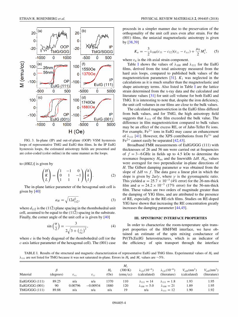
From this equation and from the list of bulk garnet prop-erties in Table I [31], we expect PMA (i.e., a negative Ku)in (111) TbIG under sufficient in-plane compressive strain.The dominant effect of the magnetoelastic contribution isillustrated by a comparison of the net anisotropy of (111)TbIG/GGG and TbIG/SGGG films. Based on the bulk lat-tice parameters of TbIG, GGG, and SGGG, we expect anepitaxial TbIG film to be under in-plane compression onGGG and in-plane tension on SGGG, which is verified bythe x-ray data in Fig. 1. The VSM hysteresis loops in Fig. 3indeed show an out-of-plane square loop for TbIG/GGG(111)[Fig. 3(a); compressive strain], while the TbIG/SGGG(111)sample [Fig. 3(b); tensile strain] shows a square in-plane
hysteresis loop. Hard-axis loops for TbIG are not shownbecause the saturation field is higher than the maximum fieldof 10 kOe available in the VSM. We attempted to ascertain theanisotropy field in a SQUID magnetometer at higher fields,but the large paramagnetic signal from the GGG substratemade it difficult to determine when the TbIG films weresaturated.
A similar calculation for EuIG films indicates that com-pressively strained films on both (001) and (111) GGG areexpected to show PMA. This is verified by the in- andout-of-plane VSM hysteresis loops in Figs. 3(c) and 3(f),together with the coupled XRD scans in Figs. 1(c) and1(d). PMA is retained up to 56-nm thickness, which isconsistent with the x-ray data showing little or no strainrelaxation. The saturation magnetization, whose measuredvalues range from 110–118 emu cm−3, is higher than thebulk value of 93 emu cm−3 [31], which may be a result ofthe excess Eu. For both the (111) and the (001) films, thecoercivity increased with increasing thickness. The anisotropyfield was determined from the hard-axis loops by fittinga straight line to the M(H) curve near zero field and ex-trapolating to the saturation magnetization. The saturationmagnetization was obtained from the easy axis hysteresisloops.
By measuring the strain state from the x-ray data and theanisotropy field from VSM, the thin-film values of λ111 andλ100 may be found. For the (111) case, a cubic unit celldistorted along one of its [111] directions becomes rhombohe-dral, and we use a rhombohedral-to-hexagonal transformationto greatly simplify the calculation of strain [40]. The transfor-mation from rhombohedral to hexagonal Miller indices [(hkl)
094405-3
ETHAN R. ROSENBERG et al. PHYSICAL REVIEW MATERIALS 2, 094405 (2018)
FIG. 3. In-plane (IP) and out-of-plane (OOP) VSM hysteresisloops of representative TbIG and EuIG thin films. In the IP EuIGhysteresis loops, the estimated anisotropy fields are presented andare color-coded (color online) in the same manner as the loops.
to (HKL)] is given by⎛⎝H
K
L
⎞⎠ =
⎛⎝1 −1 0
0 1 −11 1 1
⎞⎠
⎛⎝h
k
l
⎞⎠. (2)
The in-plane lattice parameter of the hexagonal unit cell isgiven by [40]
aH =√
12d2112, (3)
where d112 is the (112) plane spacing in the rhombohedral unitcell, assumed to be equal to the (112) spacing in the substrate.Finally, the corner angle of the unit cell α is given by [40]
sin(α
2
)= 3
2√
3 + (c
aH
)2, (4)
where c is the body diagonal of the rhombohedral cell (or thec-axis lattice parameter of the hexagonal cell). The (001) case
proceeds in a simpler manner due to the preservation of theorthogonality of the unit cell axes even after strain. For the(001) films, the uniaxial magnetoelastic anisotropy is givenby [38,39]
Ku = −3
2λ100(c11 − c12)(εzz − εxx ) + μ0
2M2
s , (5)
where εii is the ith axial strain component.Table I shows the values of λ100 and λ111 for the EuIG
films, derived from the total anisotropy measured from thehard axis loops, compared to published bulk values of themagnetostriction parameters [31]. K1 was neglected in thecalculations as it is much smaller than the magnetoelastic andshape anisotropy terms. Also listed in Table I are the latticestrain determined from the x-ray data and the calculated andliterature values [31] for unit cell volume for both EuIG andTbIG. It is interesting to note that, despite the iron deficiency,the unit cell volumes in our films are close to the bulk values.
The calculated magnetostriction in the EuIG films differedfrom bulk values, and for TbIG, the high anisotropy fieldsuggests that λ111 of the film exceeded the bulk value. Thedifference in film magnetostriction compared to bulk valuesmay be an effect of the excess RE, or of Jahn-Teller Fe ions.For example, Fe2+ ions in EuIG may cause an enhancementof λ111 [41]. However, the XPS contributions from Fe3+ andFe2+ cannot easily be separated [42,43].
Broadband FMR measurements of EuIG/GGG (111) withthicknesses of 26 and 56 nm were carried out at frequenciesof f = 3−6 GHz in fields up to 4.5 kOe to determine theresonance frequency Hres and the linewidth �H. Hres valueswere averaged for two perpendicular in-plane directions ofH. The Gilbert damping parameter α was obtained from theslope of �H vs f . The data gave a linear plot in which theslope is given by 2α/γ , where γ is the gyromagnetic ratio.This yielded α = 25.7 × 10⁻³ (4% error) for the 26-nm-thickfilm and α = 24.2 × 10⁻³ (17% error) for the 56-nm-thickfilm. These values are two orders of magnitude greater thanthe damping of YIG films, and are attributed to the presenceof RE, especially in the RE-rich films. Studies on RE-dopedYIG have shown that increasing the RE concentration greatlyincreases the damping parameter [44,45].
III. SPINTRONIC INTERFACE PROPERTIES
In order to characterize the room-temperature spin trans-port properties of the HM/FMI interface, we have ob-tained an estimate of the spin mixing conductance ofPt/(Tb,Eu)IG heterostructures, which is an indicator ofthe efficiency of spin transport through the interface
TABLE I. Results of the structural and magnetic characterization of representative EuIG and TbIG films. Experimental values of Hk andλ111 are not listed for TbIG because it was not saturated in-plane. Errors in Hk and Ms values are ∼5%.
Ms
β Hk (300 K) λijk (10−6) λijk (10−6) Vcell (nm3) Vcell (nm3)Material (degrees) εxx εzz (Oe) (emu/cc) (calculated) (literature) (calculated) (literature)
EuIG/GGG (111) 89.25 n/a n/a 1370 110 λ111 = 14 λ111 = 1.8 1.93 1.95EuIG/GGG (001) 90 0.00796 −0.00934 1880 120 λ100 = 5.0 λ100 = 21 1.89 1.95TbIG/GGG (111) 89.88 n/a n/a n/a 19 n/a λ111 = 12 1.90 1.92
094405-4

MAGNETISM AND SPIN TRANSPORT IN RARE-EARTH- … PHYSICAL REVIEW MATERIALS 2, 094405 (2018)
FIG. 4. [(a)–(c)] Anomalous-Hall-like SMR hysteresis loops forPt(4)/REIG(10) heterostructures. (d) Optical micrograph of represen-tative Hall crosses used for data acquisition.
[46,47]. Hall bar structures [see Fig. 4(d)] were fabri-cated on Pt(4 nm)/(Tb,Eu)IG(10 nm)/GGG multilayers usingphotolithography and ion milling techniques, and a lock-intechnique [5] was used to collect anomalous Hall effect(AHE)-like spin Hall magnetoresistance (SMR) hysteresisloops. All garnet films used for Hall bar fabrication had<1 nm rms roughness as characterized by atomic force mi-croscopy. A sample-dependent offset and a linear backgrounddue to the ordinary Hall effect (OHE) in Pt was subtracted, andthe results are displayed in Figs. 4(a)–4(c). The square shapeof these hysteresis loops matches the out-of-plane magnetom-etry data. However, the coercivity of the Hall cross is higherthan that of the unpatterned film due to the effects of edgeroughness on domain nucleation and pinning [5]. In-planeSMR was not measured because the probe station could notsupply large enough in-plane fields to saturate the Hall crossdevices.
The origin of the AHE in Pt/ferrite interfaces is a hotlydebated topic, with some arguing that it is at least partlydue to the magnetic proximity effect (MPE) [30,48] whileothers maintain that it is fully due to a spin Hall magne-toresistance (SMR) effect [5,49]. Meanwhile, measurementsof the magnetic polarization of Pt in direct contact witha magnetic insulator using x-ray methods indicate that theMPE is negligibly small at room temperature [50–53]. Inthe following discussion, we will assume that the AHE ispredominantly due to SMR, as in Avci et al. for the similarPt/TmIG system [5], and consistent with the lack of MPE atroom temperature in other studies [54]. The model of Chenet al. for spin mixing conductance [46] leads to
�ρ1
ρ= θ2
SH λ
dN
2λGr tanh2 dN
2λ
σ + 2λGr coth dN
2λ (6)�ρ2
ρ≈ 2θ2
SH λ2
dN
σGi tanh2 dN
2λ(σ + 2λGr coth dN
2λ
)2 ,
TABLE II. Lower bounds of Gi for Pt/REIG heterostructures,calculated in the manner described.
Material Lower bound of Gi
Pt/EuIG/GGG (111) 4.6 × 10¹² �−1 m−2
Pt/EuIG/GGG (001) 5.4 × 10¹² �−1 m−2
Pt/TbIG/GGG (111) 4.6 × 10¹² �−1 m−2
Pt/TmIG/GGG (111) Ref. [5] 7.1 × 10¹² �−1 m−2
where �ρ1 is the amplitude of an in-plane SMR loop, �ρ2 isthe amplitude of an AHE-like SMR loop, ρ is the resistivityof the Pt layer, λ is the spin diffusion length of the Pt layer,θSH is the spin Hall angle, dN is the Pt thickness, and σ = 1/ρ
is the Pt conductivity. Gr and Gi are the real and imaginaryparts of the spin mixing conductance, respectively. While Gr
can be calculated directly from a measurement of �ρ1, it isnecessary to know Gr to calculate Gi from a measurementof �ρ2. Without being able to saturate the film in planeduring the electrical measurement, �ρ1 and hence Gr couldnot be determined. However, previous results for similarlyconstructed Pt/TmIG Hall bars have values for λGr that arean order of magnitude lower than σ (2.07 × 10⁶ �−1 m−1 forour Hall bars) [5,28]. Thus we can obtain a lower bound for Gi
by dropping the Gr term in the denominator. By substitutingvalues used in a previous study on TmIG [5] for λ and θSH, wecalculate the lower bounds for Gi displayed in Table II.
These data lead to several conclusions about the spin-tronic properties of EuIG/Pt and TbIG/Pt heterostructures.First, even the lower bound of Gi for Pt/EuIG/GGGand Pt/TbIG/GGG is on the same order of magnitudeas Gi in Pt/TmIG/GGG(111) [5], indicating a similar in-terfacial spin transparency in these materials. Also, Gi
for Pt/EuIG/GGG(001) is almost identical to that ofPt/EuIG/GGG(111). The effect of crystal orientation on Gi
at metal/ferrimagnetic insulator interfaces has received lit-tle study. However, Isasa et al. [16] characterized Pt/CFOby fabricating Pt Hall bars on epitaxial CFO(001)/STO andCFO(111)/STO thin films and found Gr
111 to be significantlylower than Gr
001, especially in devices made using an ex situprocess similar to ours. This observation was related to a dif-ference in surface termination between the two orientations.A recent theoretical study by Cahaya et al., which consideredthe effects of crystal field splitting on spin mixing conduc-tance supports this claim [55]. A study of the orientationdependence of Gr in Pt/EuIG would provide an interestingcomparison to Pt/CFO [16].
IV. TEMPERATURE-DEPENDENT PROPERTIESOF TbIG FILMS
Bulk TbIG has a magnetic compensation temperature Tcomp
of 248.6 K [31], making it a convenient system for measuringspintronic phenomena near compensation (GdIG also has anear-RT Tcomp, but its weak magnetostriction limits its mag-netoelastic anisotropy). Tcomp of the TbIG films was measuredusing three different temperature-dependent techniques. Thesimplest of these was a temperature-dependent magnetizationmeasurement using VSM [Fig. 5(a)], in which a minimum in
094405-5

ETHAN R. ROSENBERG et al. PHYSICAL REVIEW MATERIALS 2, 094405 (2018)
FIG. 5. Temperature-dependent measurements of (a) magneticmoment, (b) Faraday rotation, (c) coercivity, and (d) AHE-like SMRamplitude. All of these techniques agree on a magnetic compensationpoint of ∼335 K.
the magnetic moment is clearly present near 330 K. The VSMdata yield a value for Tcomp in the range of 320 K to 340 K,indicated by a dashed line.
Temperature-dependent AHE-like SMR and Faraday rota-tion measurements are shown in Figs. 5(b) and 5(d). Insteadof going to zero, both datasets exhibit a sign change at Tcomp
due to the reorientation of the three magnetic sublattices.Below Tcomp, the octahedral Fe3+ and the Tb3+ moments areoriented parallel to the field and the tetrahedral Fe3+ momentsare antiparallel, while above Tcomp the orientation is reversed[56]. Because the Faraday effect and the SMR are sensitiveto one of the magnetic sublattices rather than to the net mag-netization, they exhibit a sign change at Tcomp [56,57]. Thesemeasurements show a compensation point of around 335 K,agreeing with the VSM result in Fig. 5(a). In addition, thecoercivity of the TbIG film as a function of temperature mea-sured from the Faraday rotation hysteresis loops is depictedin Fig. 5(c). As expected for a compensated ferrimagnet, thecoercivity diverges approaching the compensation point.
The Tcomp in our TbIG thin films is higher than that ofbulk TbIG by 85 K, which is attributed to the Fe deficientcomposition. The compensation point is determined by thedifference in magnitude of the magnetic moment on thesublattices and therefore depends on the composition [57,58].The TbIG is expected to accommodate the excess Tb as Tb4+ions (magnetic moment of 7μB) on octahedral sites normallyoccupied by Fe3+ (5μB). Fe2+ ions (4μB), which have apreference for octahedral sites over tetrahedral sites as seenin the inverse spinel magnetite, may also be present. Thestructure can then be described as consisting of one sublatticeof dodecahedral sites containing Tb3+ plus octahedral siteswith a mixture of Fe3+, Tb4+, and possibly Fe2+, and theother sublattice of tetrahedral sites containing Fe3+. The
dodecahedral plus octahedral sublattice moment exceeds thatin stoichiometric TbIG, which explains the increase in Tcomp.This is consistent with previous measurements of the Bi:TbIGsystem where it was found that reducing the Tb:Fe ratio to0.48 through the addition of Bi caused a reduction in Tcomp
to 183 K [59] because the magnetization of the dodecahedralplus octahedral sublattice was reduced with respect to that ofthe tetrahedral sublattice.
V. CONCLUSION
Epitaxial EuIG and TbIG thin films were grown using PLDon GGG and SGGG substrates. All films (from 10–60-nmthickness for EuIG and up to 90 nm for TbIG) were fullystrained to the substrate lattice parameter, with the TbIGfilm exhibiting in-plane compressive strain on GGG and in-plane tension on SGGG, and the EuIG exhibiting in-planecompression on GGG. The EuIG/GGG (111) and (100) andthe TbIG/GGG (111) films exhibit PMA. XRD indicates highcrystal quality although the films were deficient in Fe, withRE : Fe = 0.70–0.72, and the excess RE cations are believedto be accommodated in the octahedral sites. For TbIG, theincrease in average magnetic moment of the octahedral sitesis believed to be responsible for the increase in compensationtemperature of the films (∼335 K) compared to bulk, mea-sured by magnetometry, Faraday rotation, and SMR.
Pt/(Tb,Eu)IG heterostructure Hall bars showed the exis-tence of AHE-like SMR at the metal/garnet interface. Theimaginary part of the spin mixing conductance of these het-erostructures was of the same order of magnitude as that ofthe previously studied Pt/TmIG system, with values rangingfrom 4.6 to 5.4 × 10¹² �−1 m−2. Also, Gi was similar be-tween Pt/EuIG (001) and Pt/EuIG (111), in contrast to pastwork on Pt/CFO. FMR measurements of EuIG (111) werealso performed, giving the first measurement of the Gilbertdamping parameter in this material. These RE garnets exhibitpromise for future spintronic experiments and applicationsthat require ferrimagnetic insulators with PMA for differentcrystal orientations or with both PMA and a magnetic com-pensation point.
VI. METHODS
Thin Film Fabrication and Characterization. All thin filmswere deposited using pulsed laser deposition (PLD) on single-crystal GGG and SGGG substrates. The EuIG and TbIG tar-gets used were fabricated in-house by mixing Eu2O3, Tb4O7,and Fe2O3 powders in the proper weight ratios with a ball mill,calcining the green body at 1150 ˚C for 5 hours, regrinding thepowders, and sintering at 1350 ˚C for 10 hours. The single-phase iron-garnet nature of the targets was confirmed withx-ray diffraction. The growth conditions used were a substratebackside temperature of 900 ˚C, a laser fluence of 1.3 J/cm2, alaser repetition rate of 10 Hz, and an O2 pressure of 150 mTorr.After the deposition, the samples were cooled back to roomtemperature at a rate of 20 ˚C per minute in 150 mTorr O2
(slower cooling was not found to be necessary to increasesample quality). AFM RMS roughness measurements werecarried out in a Digital Instruments Nanoscope IV with a 1 µmx 1 µm scan size, XRD measurements were carried out in a
094405-6

MAGNETISM AND SPIN TRANSPORT IN RARE-EARTH- … PHYSICAL REVIEW MATERIALS 2, 094405 (2018)
Bruker D8 Discover HRXRD, and magnetic measurementswere carried out in an ADE 1660 VSM and a Quantum DesignMPMS3.
Compositional Characterization. A Thermo Scientific K-Alpha+ system was used to take high-resolution XPS spectrafor compositional analysis. Prior to data acquisition, a mildargon cluster cleaning procedure was used to remove ad-ventitious carbon without affecting film stoichiometry. High-resolution data were acquired with a 50-eV pass energy. Dataanalysis was accomplished by comparing integrated peakareas in AVANTAGE. The ALTHERMO1 relative sensitivityfactor database was used to correctly weight the atomicratios.
Hall Cross Fabrication. Hall crosses of two different sizes(100 µm and 50 µm widths) were fabricated in a two-steplithography process. First, a negative image was defined ona garnet film with a sputtered Pt overlayer and ion milling wasused to create mesa structures. Plasma ashing was necessaryto remove residual resist after this step. Then, an alignedpositive patterning step was used to define areas for Au/Tagold contacts. The spintronic properties of these Hall crosseswere measured in a homemade four-point probe station.
FMR. Broadband FMR measurements were performedusing a NanoOsc Phase FMR spectrometer and 200-µm-wide coplanar waveguide. The sample is subjected to a DC
magnetic field H along the film plane, in addition to a smalltime-varying microwave excitation field perpendicular to it.The frequency f varies from 3 to 6 GHz in steps of 0.5 GHz.For each value of f , H is swept from 4500 Oe to 0 Oe in orderto saturate the sample and then find the resonance value Hres
and the linewidth �H, by fitting the detected voltage with thederivative of the sum of a symmetric and an antisymmetricLorentzian:
P = d
dH
[S�H 2 + AS (H − Hres)
4(H − Hres)2 + �H 2
]. (7)
S and AS are arbitrary fitting constants. In order to min-imize systematic errors arising from miscalibration of Hallsensor the values of Hres were averaged with H in oppositedirections [60].
ACKNOWLEDGMENTS
The authors acknowledge support of C-SPIN, a STARnetCenter of MARCO and DARPA. This material is based uponwork supported by the National Science Foundation GraduateResearch Fellowship under Grant No. 1122374. This workmade use of the Shared Experimental Facilities supportedin part by the MRSEC Program of the National ScienceFoundation under Award No. DMR - 1419807.
[1] Y. Kajiwara, K. Harii, S. Takahashi, J. Ohe, K. Uchida, M.Mizuguchi, H. Umezawa, H. Kawai, K. Ando, K. Takanashi,S. Maekawa, and E. Saitoh, Nature (London) 464, 262 (2010).
[2] K. Uchida, H. Adachi, T. Ota, H. Nakayama, S. Maekawa, andE. Saitoh, Appl. Phys. Lett. 97, 172505 (2010).
[3] K. Uchida, H. Adachi, Y. Kajiwara, S. Maekawa, and E. Saitoh,in Recent Advances in Magnetic Insulators - From Spintronicsto Microwave Applications, edited by M. Wu and A. Hoffmann,1st ed. (Academic Press, Cambridge, MA, 2013), Vol. 64, pp.1–27.
[4] P. Li, T. Liu, H. Chang, A. Kalitsov, W. Zhang, G. Csaba, W.Li, D. Richardson, A. DeMann, G. Rimal, H. Dey, J. S. Jiang,W. Porod, S. B. Field, J. Tang, M. C. Marconi, A. Hoffmann, O.Mryasov, and M. Wu, Nat. Commun. 7, 12688 (2016).
[5] C. O. Avci, A. Quindeau, C.-F. Pai, M. Mann, L. Caretta,A. S. Tang, M. C. Onbasli, C. A. Ross, and G. S. D. Beach,Nat. Mater. 16, 309 (2017).
[6] D. Apalkov, B. Dieny, and J. M. Slaughter, Proc. IEEE 104,1796 (2016).
[7] S.-W. Lee and K.-J. Lee, Proc. IEEE 104, 1831 (2016).[8] I. M. Miron, K. Garello, G. Gaudin, P.-J. Zermatten, M. V.
Costache, S. Auffret, S. Bandiera, B. Rodmacq, A. Schuhl, andP. Gambardella, Nature (London) 476, 189 (2011).
[9] L. Liu, C.-F. Pai, Y. Li, H. W. Tseng, D. C. Ralph, and R. A.Buhrman, Science 336, 555 (2012).
[10] L. Liu, O. J. Lee, T. J. Gudmundsen, D. C. Ralph, and R. A.Buhrman, Phys. Rev. Lett. 109, 096602 (2012).
[11] K. Garello, C. O. Avci, I. M. Miron, M. Baumgartner, A.Ghosh, S. Auffret, O. Boulle, G. Gaudin, and P. Gambardella,Appl. Phys. Lett. 105, 212402 (2014).
[12] M. Kubota, K. Shibuya, Y. Tokunaga, F. Kagawa, A. Tsukazaki,Y. Tokura, and M. Kawasaki, J. Magn. Magn. Mater. 339, 63(2013).
[13] J. Fu, M. Hua, X. Wen, M. Xue, S. Ding, M. Wang, P. Yu, S.Liu, J. Han, C. Wang, H. Du, Y. Yang, and J. Yang, Appl. Phys.Lett. 110, 202403 (2017).
[14] H. Wang, C. Du, P. C. Hammel, and F. Yang, Phys. Rev. B 89,134404 (2014).
[15] W. Yang, S. Yang, Q. Zhang, Y. Xu, S. Shen, J. Liao, J. Teng,C. Nan, L. Gu, Y. Sun, K. Wu, and Y. Li, Appl. Phys. Lett. 105,092411 (2014).
[16] M. Isasa, A. Bedoya-Pinto, S. Vélez, F. Golmar, F. Sánchez,L. E. Hueso, J. Fontcuberta, and F. Casanova, Appl. Phys. Lett.105, 142402 (2014).
[17] P. C. Dorsey, P. Lubitz, D. B. Chrisey, and J. S. Horwitz,J. Appl. Phys. 79, 6338 (1998).
[18] M. Kubota, A. Tsukazaki, F. Kagawa, K. Shibuya, Y. Tokunaga,M. Kawasaki, and Y. Tokura, Appl. Phys. Express 5, 103002(2012).
[19] A. Quindeau, C. O. Avci, W. Liu, C. Sun, M. Mann, A. S. Tang,M. C. Onbasli, D. Bono, P. M. Voyles, Y. Xu, J. Robinson, G.S. D. Beach, and C. A. Ross, Adv. Electron. Mater. 3, 1600376(2016).
[20] H. Yamahara, M. Mikami, M. Seki, and H. Tabata, J. Magn.Magn. Mater. 323, 3143 (2011).
[21] N. Kumar, N. G. Kim, Y. A. Park, N. Hur, J. H. Jung,K. J. Han, and K. J. Yee, Thin Solid Films 516, 7753(2008).
[22] E. Lage, L. Beran, A. U. Quindeau, L. Ohnoutek, M. Kucera,R. Antos, S. R. Sani, G. F. Dionne, M. Veis, and C. A. Ross,APL Mater. 5, 036104 (2017).
[23] E. Popova, A. F. Franco Galeano, M. Deb, B. Warot-Fonrose,H. Kachkachi, F. Gendron, F. Ott, B. Berini, and N. Keller,J. Magn. Magn. Mater. 335, 139 (2013).
[24] P. Sellappan, C. Tang, J. Shi, and J. E. Garay, Mater. Res. Lett.5, 41 (2017).
094405-7

ETHAN R. ROSENBERG et al. PHYSICAL REVIEW MATERIALS 2, 094405 (2018)
[25] S. Geprägs, A. Kehlberger, F. Della Coletta, Z. Qiu, E.-J.Guo, T. Schulz, C. Mix, S. Meyer, A. Kamra, M. Altham-mer, H. Huebl, G. Jakob, Y. Ohnuma, H. Adachi, J. Barker,S. Maekawa, G. E. W. Bauer, E. Saitoh, R. Gross, S. T.B. Goennenwein, and M. Kläui, Nat. Commun. 7, 10452(2016).
[26] C. L. Jermain, H. Paik, S. V. Aradhya, R. A. Buhrman, D.G. Schlom, and D. C. Ralph, Appl. Phys. Lett. 109, 192408(2016).
[27] C. N. Wu, C. C. Tseng, K. Y. Lin, C. K. Cheng, S. L. Yeh, Y. T.Fanchiang, M. Hong, and J. Kwo, AIP Adv. 8, 055904 (2018).
[28] C. O. Avci, E. Rosenberg, M. Baumgartner, L. Beran, A.Quindeau, P. Gambardella, C. A. Ross, and G. S. D. Beach,Appl. Phys. Lett. 111, 072406 (2017).
[29] J. Li, G. Yu, C. Tang, Y. Liu, Z. Shi, Y. Liu, A. Navabi, M.Aldosary, Q. Shao, K. L. Wang, R. Lake, and J. Shi, Phys. Rev.B 95, 241305 (2017).
[30] C. Tang, P. Sellappan, Y. Liu, Y. Xu, J. E. Garay, and J. Shi,Phys. Rev. B 94, 140403 (2016).
[31] Landolt-Börnstein - Group III Crystal and Solid State Physics,edited K.-H. Hellwege and A. M. Hellwege (Springer-Verlag,Berlin/Heidelberg, 1978), Vol. 12a.
[32] S. Iida, J. Phys. Soc. Japan 22, 1201 (1967).[33] Y. Sun, Y.-Y. Song, H. Chang, M. Kabatek, M. Jantz, W.
Schneider, M. Wu, H. Schultheiss, and A. Hoffmann, Appl.Phys. Lett. 101, 152405 (2012).
[34] D.-Y. Lu, T. Ogata, H. Unuma, X.-C. Li, N.-N. Li, and X.-Y.Sun, Solid State Ionics 201, 6 (2011).
[35] D.-Y. Lu, Solid State Ionics 276, 98 (2015).[36] M. Balaguer, C.-Y. Yoo, H. J. M. Bouwmeester, and J. M. Serra,
J. Mater. Chem. A 1, 10234 (2013).[37] E.-J. Cho and S.-J. Oh, Phys. Rev. B 59, R15613 (1999).[38] D. H. Kim, N. M. Aimon, L. Bi, J. M. Florez, G. F. Dionne, and
C. A. Ross, J. Phys. Condens. Matter 25, 026002 (2013).[39] R. O’Handley, Modern Magnetic Materials: Principles and
Applications, 1st ed. (Wiley, New York, NY, 1999).[40] B. D. Cullity, Elements of X-Ray Diffraction, 2nd ed. (Addison-
Wesley Publishing Company, Inc, Reading, MA, 1978).[41] G. F. Dionne, Magnetic Oxides, 1st ed. (Springer
Science+Business Media, New York, NY, 2009).[42] Z. Zhou, Y. Zhang, Z. Wang, W. Wei, W. Tang, J. Shi, and R.
Xiong, Appl. Surf. Sci. 254, 6972 (2008).[43] T.-C. Lin, G. Seshadri, and J. A. Kelber, Appl. Surf. Sci. 119,
83 (1997).
[44] T. Taffary, D. Autissier, F. Boust, and H. Pascard, IEEE Trans.Magn. 34, 1384 (1998).
[45] V. Sharma and B. K. Kuanr, J. Alloys Compd. 748, 591 (2018).[46] Y.-T. Chen, S. Takahashi, H. Nakayama, M. Althammer, S. T.
B. Goennenwein, E. Saitoh, and G. E. W. Bauer, Phys. Rev. B87, 144411 (2013).
[47] M. Weiler, G. Woltersdorf, M. Althammer, H. Huebl, andS. T. B. Goennenwein, in Solid State Physics (Academic Press,Cambridge, MA, 2013), pp. 123–156.
[48] B. F. Miao, S. Y. Huang, D. Qu, and C. L. Chien, Phys. Rev.Lett. 112, 236601 (2014).
[49] M. Althammer, S. Meyer, H. Nakayama, M. Schreier, S.Altmannshofer, M. Weiler, H. Huebl, S. Geprägs, M. Opel, R.Gross, D. Meier, C. Klewe, T. Kuschel, J.-M. Schmalhorst, G.Reiss, L. Shen, A. Gupta, Y.-T. Chen, G. E. W. Bauer, E. Saitoh,and S. T. B. Goennenwein, Phys. Rev. B 87, 224401 (2013).
[50] S. Geprägs, S. Meyer, S. Altmannshofer, M. Opel, F. Wilhelm,A. Rogalev, R. Gross, and S. T. B. Goennenwein, Appl. Phys.Lett. 101, 262407 (2012).
[51] Y. M. Lu, Y. Choi, C. M. Ortega, X. M. Cheng, J. W. Cai, S. Y.Huang, L. Sun, and C. L. Chien, Phys. Rev. Lett. 110, 147207(2013).
[52] S. Geprägs, S. T. B. Goennenwein, M. Schneider, F. Wilhelm,K. Ollefs, A. Rogalev, M. Opel, and R. Gross, arXiv:1307.4869(2013).
[53] T. Kuschel, C. Klewe, J.-M. Schmalhorst, F. Bertram, O.Kuschel, T. Schemme, J. Wollschläger, S. Francoual, J.Strempfer, A. Gupta, M. Meinert, G. Götz, D. Meier, and G.Reiss, Phys. Rev. Lett. 115, 097401 (2015).
[54] C. Onur Avci, E. Rosenberg, J. Mendil, L. Beran,P. Gambardella, C. A. Ross, and G. S. D. Beach (unpublished).
[55] A. B. Cahaya, A. O. Leon, and G. E. W. Bauer, Phys. Rev. B96, 144434 (2017).
[56] A. K. Zvezdin and V. A. Kotov, Modern Magnetooptics andMagnetooptical Materials (CRC, Boca Raton, FL, 1997).
[57] K. Ganzhorn, J. Barker, R. Schlitz, B. A. Piot, K. Ollefs, F.Guillou, F. Wilhelm, A. Rogalev, M. Opel, M. Althammer, S.Geprägs, H. Huebl, R. Gross, G. E. W. Bauer, and S. T. B.Goennenwein, Phys. Rev. B 94, 094401 (2016).
[58] J. Finley and L. Liu, Phys. Rev. Appl. 6, 054001 (2016).[59] M. Guillot, H. Le Gall, J. M. Desvignes, and M. Artinian, IEEE
Trans. Magn. 30, 4419 (1994).[60] C. Gonzalez-Fuentes, R. K. Dumas, and C. García, J. Appl.
Phys. 123, 023901 (2018).
094405-8