magnetic wedges in compression stations - rpm eng design, vibration, motor-operating temperature,...
TRANSCRIPT

1077-2618/12/$31.00©2012 IEEE
BY ROBERT HANNA& DENN I S W . SCHMI T T
THIS ARTICLE PRESENTS
the failure analysis and field
measurements of five 7,500-
hp induction motors driv-
ing reciprocating compressors for a natural gas
compression station. The failure analysis examined
fan design, vibration, motor-operating temperature,
compressor loading profile, number of motor starts, and
ambient temperature. A comparison between direct online
motor starting and soft starting using an adjustable speed drive
(ASD) and the impact on motor performance are presented. The
settings and historical data gathered from the microprocessor pro-
tection relay for the motors are also covered and discussed.
Compressor Stations
From 2005 to 2007, five 7,500-hp, 4,160-V, 1,189-r/min induction motors were installed at compressor station A,
where all had direct online starting. A sixth motor of the same rating was installed at compressor station B using a
3,000-hp ASD for the purpose of a soft-start application. This application of the ASD was necessary as a result of utility
power system requirements. The two compressor stations were less than 20 mi apart. In May 2007, one of the five
motors in station A suffered a cooling fan failure and was sent to a motor shop for repair. In November 2007, a second
motor at the same location experienced a similar fan failure and was shipped to the same motor shop for repair. As a pre-
cautionary measure and under planned conditions, the end user decided to take the remaining 7,500-hp induction
motors (with the original fan design) to the motor shop one at a time and retrofit them with a modified cooling fan
design. In August 2008, when the last motor had its fan replaced, the motor repair shop noticed evidence of winding
material close to the nondrive end. In each case, the rotor had to be removed in for fan replacement. Because of the
winding debris, the stator was thoroughly examined. The subsequent inspection revealed that many of the magnetic
wedges, fitted in the stator slots, were either partially missing or loose. In this article, we present findings for prema-
ture failure of both cooling fans and magnetic wedges for 7,500-hp induction motors with three years of service.
Digital Object Identifier 10.1109/MIAS.2012.2191340
Date of publication: 9 May 2012
Magnetic wedges incompression stations
40
IEEE
INDUSTR
YAPPLICATIONS
MAGAZIN
E�
JULYjA
UGUST
2012�
WW
W.IEEE.O
RG/IAS

Fan FailureIn 2007, two motors had serious cool-ing fan failures, which required themotors to be removed from service andrepaired. These events called for areview of the fan design by the originalmotor manufacturer.
Fan Failure Mechanical AnalysisIn May 2007 and again in November,two separate fan failures occurred ontwo of the then five installed electric-driven gas compressor packages at agas-gathering compressor station inwestern Colorado. These two installa-tions have identical 7,500-hp electricmotors, each driving a two-stage, six-throw natural gas compressor. Thefailure investigation determined thatthe likely sequence of events that led to the eventual fanfailure were as follows:
n fan bolts became loosen fan became loosen vibration levels began to escalaten bolts began to fail and some vibrated outn vibration levels continued to escalaten all remaining bolts failed and fan fell onto steel bossn the unit shutted down due to very high vibrationlevels.
The design of the fan for this motor is a bolted joint, wherea cast aluminum fan is bolted to a machined steel boss thathas a shrink fit onto the steel rotor shaft. In both cases, whenthe fan failed, many of the bolts in the assembly were sheared,and the cast aluminum fan was damaged at the bolt holes.The failure modes for the two cooling fans were essentiallyidentical. The aluminum fan housing had many bolt holesthat were key slotted, whereas others had no damage due tothe bolt backing out completely before failure (Figure 1).There was also significant evidence of fretting corrosion onthe mating surface between the fan and steel boss, indicatingsubstantial and/or frequent relative motion (Figure 2).
The 1,200 r/min units were started at full voltage withthe compressor unloaded and, at the time of the failures,
were shut down with the compressorfully loaded. These operational condi-tions led to very high acceleration dur-ing start-up (2.5 s) and approximatelytwice the start-up acceleration magni-tude during shutdown. This combina-tion of inertial forces caused the fan toslip during start-up and fully reverseduring shutdown. It is believed thatthis small rotational translation is whatled to the development of fretting cor-rosion. As the surface asperities grew innumber and size, the effectiveness ofthe bolted joint decreased. Total rota-tional slip of the fan with respect to thefan boss likely increased. This relativemotion combined with some inherentmachine vibration and a low initialbolt torque ultimately allowed some of
the bolts to become loose and vibrate out.An engineering mechanics and dynamics analysis was
performed for the original fan assembly design. This analy-sis revealed that the fan’s bolted joint factor of safety (Sf),defined as the ratio of the total clamping force to the iner-tial force of the fan, had a potential less than one.
The motor manufacturer already had an improved fandesign that was available. This improved design used33% more bolts with 78% more cross-sectional area andincluded an additional steel ring as part of the improveddesign. This steel ring was installed on inside of the fanand created a steel-aluminum-steel bolted joint assembly.This in combination with more and larger bolts increasedSf to approximately five.
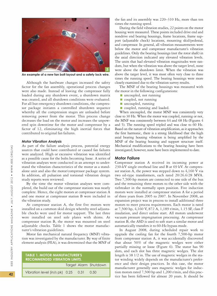
In addition to the improved design, the choice of thebolt was also evaluated. The original and replacement boltsprovided by the motor manufacturer were property class4.8 (approximately SAE grade 2), which is a low-strength,mild steel bolt. For the fan upgrade process, two changeswere made to the bolts. Property class 8.8 (approximatelySAE grade 5) bolts were selected for use, and all of the boltheads were drilled to fix the stainless steel safety lockingwire (Figure 3). Changing the bolt property class allowedthe Sf to be increased again to approximately 8.5.
1One damaged fan bolt hole and another with no damage.
2Fan-mounting surface-fretting corrosion damage.
THEREWAS ACLOSE
CORRELATIONBETWEEN THEAMBIENT AIRTEMPERATUREANDMOTORTEMPERATURE
RISE.
41
IEEE
INDUSTR
YAPPLIC
ATIO
NS
MAGAZIN
E�
JULYjA
UGUST
2012�
WW
W.IE
EE.O
RG/IA
S
Although the hardware changes increased the safetyfactor for the fan assembly, operational process changeswere also made. Instead of leaving the compressor fullyloaded during any shutdown event, a shutdown matrixwas created, and all shutdown conditions were evaluated.For all but emergency shutdown conditions, the compres-sor package initiates a controlled shutdown sequencewhereby all the compression stages are unloaded beforeremoving power from the motor. This process changedecreases the load on the motor and increases the unpow-ered spin downtime for the motor and compressor by afactor of 12, eliminating the high inertial forces thatcontributed to original fan failures.
Motor Vibration AnalysisAs part of the failure analysis process, potential energysources that could have contributed or caused fan failureswere analyzed. High or excessive vibration was identifiedas a possible cause for the bolts becoming loose. A series ofvibration analyses were conducted in an attempt to under-stand the vibration characteristics of the motor as a stand-alone unit and also the motor/compressor package system.In addition, all pulsation and torsional vibration designstudy reports were reviewed.
By the time the motor vibration analyses were com-pleted, the build out of the compressor stations was nearlycomplete. Hence, the eight motors at compressor station Aand one motor at compressor station B were included inthe vibration study.
At compressor station A, the first five motors wereinstalled on a common skid design whereby steel adjusta-ble chocks were used for motor support. The last threewere installed on steel sole plates with shims. Atcompressor station B, the motor was mounted on steeladjustable chocks. Table 1 shows the motor manufac-turer’s vibration guidelines.
Motor fan mechanical natural frequency (MNF) vibra-tion was investigated by the manufacturer. By way of finiteelement analysis (FEA), it was determined that the MNF of
the fan and its assembly was 220–310 Hz, more than tentimes the running speed.
During the field vibration studies, 22 points on the motorhousing were measured. These points included drive end andnondrive end bearing housings, frame locations, frame sup-port (adjustable chock) locations, mounting skid/pedestal,and compressor. In general, all vibration measurements werebelow the motor and compressor manufacturer’s vibrationguidelines. Only the bearing housings (not the rotor shaft) inthe axial direction indicated any elevated vibration levels.The units that had elevated vibration magnitudes were ran-dom, but when the vibration was above the target level, nonewere above the shutdown limit. When the vibration wasabove the target level, it was most often very close to threetimes the running speed. The bearing housings were moreclosely examined due to the vibration survey results.
The MNF of the bearing housings was measured withthe motor in the following configurations:
n uncoupled, not runningn coupled, not runningn uncoupled, runningn coupled, running and loaded.When uncoupled, the motor MNF was consistently very
close to 30 Hz.When the motor was coupled, running or not,the MNF was consistently between 64 and 68 Hz (Figures 4and 5). The running speed tripled and was close to 60 Hz.Based on the nature of vibration amplification, as it approachesthe first harmonic, there is a strong likelihood that the highaxial bearing housing vibration is being amplified by theMNF of the bearing housing and support structure itself.Mechanical modifications to the bearing housing have beeninvestigated; however, none have been implemented to date.
Motor FailureCompressor station A received its incoming power at230-kV single overhead line and B at 69 kV. At compres-sor station A, the power was stepped down to 4,160 V viatwo oil-type transformers, each rated 20/26.6/28 MVA.Two 7,500-hp motors are connected to one side of the busand the remaining three motors to the other side with thetiebreaker in the normally open position. Five inductionmotors were installed at compressor station A for a periodof three years from 2005 to 2007. In November 2008, anexpansion project was in process to install additional threemotors to meet process requirements. Each motor is ratedat 7,500 hp, 4,160 V, 872 A, 1,189 r/min, 1.15 SF, class Finsulation, and direct online start. All motors underwentvacuum pressure impregnation processing. At compressorstation B, the ASD is used to soft start a similar motor andautomatically transfers it to 60-Hz bypass mode.
In August 2008, during scheduled repair work toupgrade the cooling fan for the fourth 7,500-hp motorfrom compressor station A, it was accidentally discoveredthat about 50% of the magnetic wedges were eitherpartially missing or loose (Figure 6). The stator has 90slots, and each slot has three magnetic wedges. The slotlength is 38 1/2 in. The use of magnetic wedges in the sta-tor winding widely depends on the manufacturer’s prefer-ence and their design practices. In this case, the motormanufacturer generally uses magnetic wedges for induc-tion motors rated 7,500 hp and 1,200 r/min, and this prac-tice has been followed for almost 20 years. It should be
TABLE 1. MOTOR MANUFACTURER’SRECOMMENDED VIBRATION LIMITS.
Target Alarm Shutdown
Vibration level (in/s pk) 0.25 0.31 0.50
3An example of a new fan bolt layout and a safety lock wire.
42
IEEE
INDUSTR
YAPPLICATIONS
MAGAZIN
E�
JULYjA
UGUST
2012�
WW
W.IEEE.O
RG/IAS

noted that information regarding thetype of wedges used in stator slots isnot normally published, shared, orprovided by any motor manufacturerat the bidding stage, unless it isspecifically requested or called for inthe engineering specification. Thisinformation is considered a detaildesign and privy to the manufac-turer’s practices.
Magnetic wedges, when comparedwith nonmagnetic wedges, haveboth pros and cons [1], [2]. Thekey advantages of using magneticwedges are
n lower stator temperature riseand reduced core losses
n slightly higher motor efficiencyn reduced inrush currentn reduced noise level.A typical magnetic wedge, mate-
rial comprises 75% iron powder, 7%glass mat, and 18% epoxy resin.Magnetic wedges are more suscepti-ble to failure when compared withnonmagnetic wedges because theyare more brittle due to the highpercentage of iron powder. In addi-tion, for reciprocating-type loads, themagnetic wedges by their nature aresubject to cyclic mechanical forces(120 times per second) so that if there is any freedom tomove in the stator slot, fretting can occur, and the move-ment will slowly increase until wedge failure occurs. Uponfailure, magnetic wedges normally disintegrate into verysmall pieces and get crushed in the small air gap (2.8 mm)between the stator and rotor. Typically, upon failure, mag-netic wedges leave a distinct color mark on the rotor sur-face. The reliability and longevity of magnetic wedges aregreatly impacted by the following factors:
n The number of full-voltage motor starts should beminimized as it causes excessive magnetic andthermal stresses on the magnetic wedges. In thiscase, the data retrieved from motor protectionmicroprocessor relay show that the number ofmotor starts is high, and the motor is started, onaverage, once every three days.
n Motor vibration should be kept within design lim-its. High vibration could result in weakening ofmagnetic wedges and possible failure.
n Motors should normally run at or below 80 �C(176 �F) temperature rise. In this case, the motorswere running at an elevated temperature rise,although the actual measured motor loading is atapproximately 80% of rating. This situation iscompounded because of poor air ventilation in thecompressor building for station A and elevatedambient temperature during summer months. Onthe other hand, forced ventilation fans wereinstalled at compressor building B.
n The surrounding area of compressor building A isfairly dusty, and all the motors have weather
protected type II (WPII) enclosures without aprovision to add air filters.
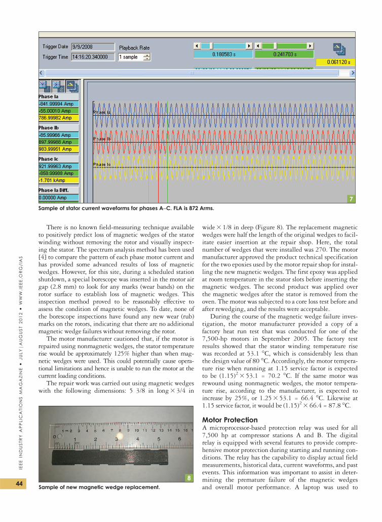
n It is common that a reciprocating compressor loadprofile exerts greater electromagnetic forces on themagnetic wedges due to the pulsating currents andthe motor being run at a rated load. This was nota factor in this case because the stator current pro-file (Figure 7) is uniform (nonpulsating) and themotor was running at 80% load. MG1-2003standard [3] calls for the current variation ininduction motors driving a reciprocating-type loadnot to exceed 66% of full load value. In this case,the variation between minimum and maximumcurrent measurements was insignificant, less than2%, well within MG1 requirements.
32.5
21.5
10.5
0
10.80.60.40.20
0 10 20 30 40 50 60 70 80 90 100
110
120
130
140
150
160
170
180
190
200
Hz
Coh
eren
ce
in/s
/ibf p
k
CoherenceUnit 7, Motor-Free End, Uncoupled, Not Running, Axial, MNF
4An MNF of uncoupled motor, not running.
CoherenceUnit 7, Motor-Free End, Uncoupled, Running, Axial, MNF
5
20
15
10
5
0
10.80.60.40.20
0 10 20 30 40 50 60 70 80 90 100
110
120
130
140
150
160
170
180
190
200
Hz
Coh
eren
ce
in/s
/ibf p
k 67 Hz
An MNF of uncoupled motor running.
6Stator winding at the motor repair shop. White chalk marksidentify partially damaged or loose magnetic wedges.
43
IEEE
INDUSTR
YAPPLIC
ATIO
NS
MAGAZIN
E�
JULYjA
UGUST
2012�
WW
W.IE
EE.O
RG/IA
S
There is no known field-measuring technique availableto positively predict loss of magnetic wedges of the statorwinding without removing the rotor and visually inspect-ing the stator. The spectrum analysis method has been used[4] to compare the pattern of each phase motor current andhas provided some advanced results of loss of magneticwedges. However, for this site, during a scheduled stationshutdown, a special borescope was inserted in the motor airgap (2.8 mm) to look for any marks (wear bands) on therotor surface to establish loss of magnetic wedges. Thisinspection method proved to be reasonably effective toassess the condition of magnetic wedges. To date, none ofthe borescope inspections have found any new wear (rub)marks on the rotors, indicating that there are no additionalmagnetic wedge failures without removing the rotor.
The motor manufacturer cautioned that, if the motor isrepaired using nonmagnetic wedges, the stator temperaturerise would be approximately 125% higher than when mag-netic wedges were used. This could potentially cause opera-tional limitations and hence is unable to run the motor at thecurrent loading conditions.
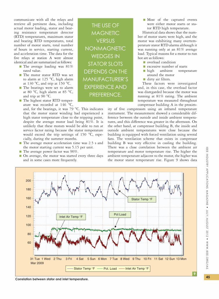
The repair work was carried out using magnetic wedgeswith the following dimensions: 5 3/8 in long3 3/4 in
wide3 1/8 in deep (Figure 8). The replacement magneticwedges were half the length of the original wedges to facil-itate easier insertion at the repair shop. Here, the totalnumber of wedges that were installed was 270. The motormanufacturer approved the product technical specificationfor the two epoxies used by the motor repair shop for instal-ling the new magnetic wedges. The first epoxy was appliedat room temperature in the stator slots before inserting themagnetic wedges. The second product was applied overthe magnetic wedges after the stator is removed from theoven. The motor was subjected to a core loss test before andafter rewedging, and the results were acceptable.
During the course of the magnetic wedge failure inves-tigation, the motor manufacturer provided a copy of afactory heat run test that was conducted for one of the7,500-hp motors in September 2005. The factory testresults showed that the stator winding temperature risewas recorded at 53.1 �C, which is considerably less thanthe design value of 80 �C. Accordingly, the motor tempera-ture rise when running at 1.15 service factor is expectedto be (1.15)2 3 53.1 = 70.2 �C. If the same motor wasrewound using nonmagnetic wedges, the motor tempera-ture rise, according to the manufacturer, is expected toincrease by 25%, or 1.253 53.1 = 66.4 �C. Likewise at1.15 service factor, it would be (1.15)2 3 66.4 = 87.8 �C.
Motor ProtectionA microprocessor-based protection relay was used for all7,500 hp at compressor stations A and B. The digitalrelay is equipped with several features to provide compre-hensive motor protection during starting and running con-ditions. The relay has the capability to display actual fieldmeasurements, historical data, current waveforms, and pastevents. This information was important to assist in deter-mining the premature failure of the magnetic wedgesand overall motor performance. A laptop was used to
7Sample of stator current waveforms for phases A–C. FLA is 872 Arms.
8Sample of new magnetic wedge replacement.
44
IEEE
INDUSTR
YAPPLICATIONS
MAGAZIN
E�
JULYjA
UGUST
2012�
WW
W.IEEE.O
RG/IAS
communicate with all the relays andretrieve all pertinent data, includingactual motor loading, stator and bear-ing resistance temperature detector(RTD) temperatures, maximum statorand bearing RTD temperatures, totalnumber of motor starts, total numberof hours in service, starting current,and acceleration time. The data for thefive relays at station A were almostidentical and are summarized as follows:
n The average loading was 81%rated value.
n The motor stator RTD was setto alarm at 125 �C, high alarmat 130 �C, and trip at 150 �C.
n The bearings were set to alarmat 80 �C, high alarm at 85 �C,and trip at 90 �C.
n The highest stator RTD temper-ature was recorded at 146 �C,and, for the bearings, it was 79 �C. This indicatesthat the motor stator winding had experienced ahigh stator temperature close to the tripping point,despite the average motor load being 81%. It isunlikely that these motors would be able to run atservice factor rating because the stator temperaturewould exceed the trip settings of 150 �C, espe-cially, during the summer months.
n The average motor acceleration time was 2.5 s andthe motor starting current was 5.15 per unit.
n The average power factor was 90%.n On average, the motor was started every three daysand in some cases more frequently.
n Most of the captured eventswere either motor starts or sta-tor RTD high temperature.
Historical data shows that the num-ber of motor starts were high, and themotor was exhibiting many overtem-perature stator RTD alarms although itwas running only at an 81% averageload. Typical reasons for a motor to runhot are as follows:
n overload conditionn excessive number of startsn high ambient temperaturearound the motor
n dirty air filters.These factors were investigated
and, in this case, the overload factorwas disregarded because the motor wasrunning at 81% rating. The ambienttemperature was measured throughoutcompressor building A in the proxim-
ity of five compressors using an infrared temperatureinstrument. The measurement showed a considerable dif-ference between the outside and inside ambient tempera-tures, and this difference was greater in the afternoon. Onthe other hand, at compressor building B, the inside andoutside ambient temperatures were close because thebuilding is equipped with forced ventilation using severalfans. The ventilation scheme that exists in compressorbuilding B was very effective in cooling the building.There was a close correlation between the ambient airtemperature and motor temperature rise. The higher theambient temperature adjacent to the motor, the higher wasthe motor stator temperature rise. Figure 9 shows data
31 Tue 1 Wed 2 Thu 3 Fri 4 Sat 5 Sun 6 Mon 7 Tue 8 Wed 9 Thu 10 Fri 11 Sat 12 Sun 13 Mon
200
180
160
140
120
100
80
60
Mar 2009
Inlet Air Temp °FStator Temp °F Pct. Load
Inlet Air Temp °FPct Load
Stator Temp °F
9Correlation between stator and inlet temperature.
THE USE OFMAGNETICVERSUS
NONMAGNETICWEDGES IN
STATOR SLOTSDEPENDS ON THEMANUFACTURER’SEXPERIENCEANDPREFERENCE.
45
IEEE
INDUSTR
YAPPLIC
ATIO
NS
MAGAZIN
E�
JULYjA
UGUST
2012�
WW
W.IE
EE.O
RG/IA
S
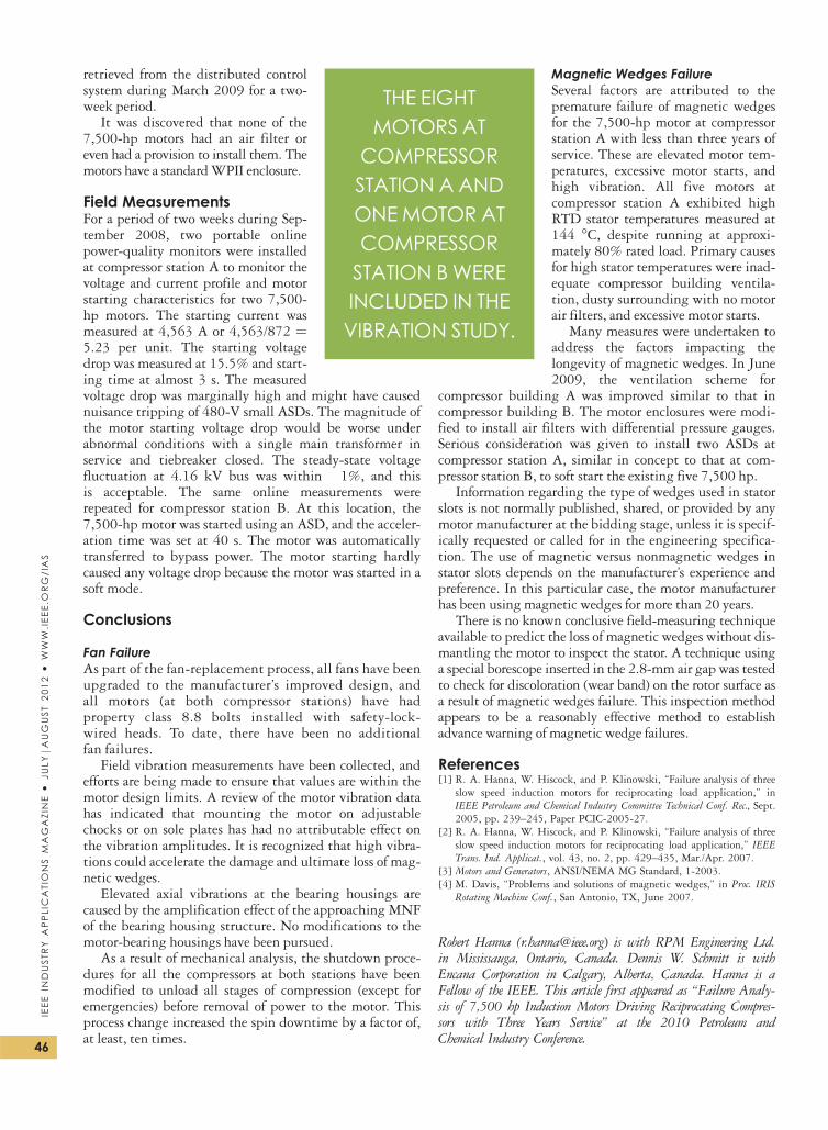
retrieved from the distributed controlsystem during March 2009 for a two-week period.
It was discovered that none of the7,500-hp motors had an air filter oreven had a provision to install them. Themotors have a standardWPII enclosure.
Field MeasurementsFor a period of two weeks during Sep-tember 2008, two portable onlinepower-quality monitors were installedat compressor station A to monitor thevoltage and current profile and motorstarting characteristics for two 7,500-hp motors. The starting current wasmeasured at 4,563 A or 4,563/872 ¼5.23 per unit. The starting voltagedrop was measured at 15.5% and start-ing time at almost 3 s. The measuredvoltage drop was marginally high and might have causednuisance tripping of 480-V small ASDs. The magnitude ofthe motor starting voltage drop would be worse underabnormal conditions with a single main transformer inservice and tiebreaker closed. The steady-state voltagefluctuation at 4.16 kV bus was within �1%, and thisis acceptable. The same online measurements wererepeated for compressor station B. At this location, the7,500-hp motor was started using an ASD, and the acceler-ation time was set at 40 s. The motor was automaticallytransferred to bypass power. The motor starting hardlycaused any voltage drop because the motor was started in asoft mode.
Conclusions
Fan FailureAs part of the fan-replacement process, all fans have beenupgraded to the manufacturer’s improved design, andall motors (at both compressor stations) have hadproperty class 8.8 bolts installed with safety-lock-wired heads. To date, there have been no additionalfan failures.
Field vibration measurements have been collected, andefforts are being made to ensure that values are within themotor design limits. A review of the motor vibration datahas indicated that mounting the motor on adjustablechocks or on sole plates has had no attributable effect onthe vibration amplitudes. It is recognized that high vibra-tions could accelerate the damage and ultimate loss of mag-netic wedges.
Elevated axial vibrations at the bearing housings arecaused by the amplification effect of the approaching MNFof the bearing housing structure. No modifications to themotor-bearing housings have been pursued.
As a result of mechanical analysis, the shutdown proce-dures for all the compressors at both stations have beenmodified to unload all stages of compression (except foremergencies) before removal of power to the motor. Thisprocess change increased the spin downtime by a factor of,at least, ten times.
Magnetic Wedges FailureSeveral factors are attributed to thepremature failure of magnetic wedgesfor the 7,500-hp motor at compressorstation A with less than three years ofservice. These are elevated motor tem-peratures, excessive motor starts, andhigh vibration. All five motors atcompressor station A exhibited highRTD stator temperatures measured at144 �C, despite running at approxi-mately 80% rated load. Primary causesfor high stator temperatures were inad-equate compressor building ventila-tion, dusty surrounding with no motorair filters, and excessive motor starts.
Many measures were undertaken toaddress the factors impacting thelongevity of magnetic wedges. In June2009, the ventilation scheme for
compressor building A was improved similar to that incompressor building B. The motor enclosures were modi-fied to install air filters with differential pressure gauges.Serious consideration was given to install two ASDs atcompressor station A, similar in concept to that at com-pressor station B, to soft start the existing five 7,500 hp.
Information regarding the type of wedges used in statorslots is not normally published, shared, or provided by anymotor manufacturer at the bidding stage, unless it is specif-ically requested or called for in the engineering specifica-tion. The use of magnetic versus nonmagnetic wedges instator slots depends on the manufacturer’s experience andpreference. In this particular case, the motor manufacturerhas been using magnetic wedges for more than 20 years.
There is no known conclusive field-measuring techniqueavailable to predict the loss of magnetic wedges without dis-mantling the motor to inspect the stator. A technique usinga special borescope inserted in the 2.8-mm air gap was testedto check for discoloration (wear band) on the rotor surface asa result of magnetic wedges failure. This inspection methodappears to be a reasonably effective method to establishadvance warning of magnetic wedge failures.
References[1] R. A. Hanna, W. Hiscock, and P. Klinowski, “Failure analysis of three
slow speed induction motors for reciprocating load application,” inIEEE Petroleum and Chemical Industry Committee Technical Conf. Rec., Sept.2005, pp. 239–245, Paper PCIC-2005-27.
[2] R. A. Hanna, W. Hiscock, and P. Klinowski, “Failure analysis of threeslow speed induction motors for reciprocating load application,” IEEETrans. Ind. Applicat., vol. 43, no. 2, pp. 429–435, Mar./Apr. 2007.
[3] Motors and Generators, ANSI/NEMA MG Standard, 1-2003.[4] M. Davis, “Problems and solutions of magnetic wedges,” in Proc. IRIS
Rotating Machine Conf., San Antonio, TX, June 2007.
Robert Hanna ([email protected]) is with RPM Engineering Ltd.in Mississauga, Ontario, Canada. Dennis W. Schmitt is withEncana Corporation in Calgary, Alberta, Canada. Hanna is aFellow of the IEEE. This article first appeared as “Failure Analy-sis of 7,500 hp Induction Motors Driving Reciprocating Compres-sors with Three Years Service” at the 2010 Petroleum andChemical Industry Conference.
THE EIGHTMOTORS AT
COMPRESSORSTATION A ANDONEMOTOR ATCOMPRESSORSTATION BWEREINCLUDED IN THEVIBRATION STUDY.
46
IEEE
INDUSTR
YAPPLICATIONS
MAGAZIN
E�
JULYjA
UGUST
2012�
WW
W.IEEE.O
RG/IAS