magnetic powdercores - mantech · introduction arnold manufactures the world’s largest selection...
TRANSCRIPT

MagneticPowder Cores
p. 17.1 February 2003
ARNOLD MAGNETICS LTDPowder Core Division
Introduction
Arnold manufactures the world’s largest selection of magneticmaterials. We are magnetic specialists of both hard and softmagnetic materials. This product information guide is focusedon our soft magnetic powder core products; MolybdenumPermalloy Powder, SUPER-MSS™, and HI-FLUX™.
Today, electrical design engineers need to identify and compareproduct capabilities, performance and effectiveness for highfrequency power conversion inductors, noise filters and varioustuned circuit applications to meet their design objectives. Toassist in this selection process, we have included the followinginformation:
• How to order parts• Design information• Formulas and definitions for design calculations• Comparative magnetic curves for performance evaluation• Electrical and physical specifications with part numbers• ”Q“ curves for Molybdenum Permalloy Powder cores
In 1995 Arnold initiated a complete upgrade of our powdercore manufacturing facility providing the most advancedequipment to process, control and monitor our products. Theupgrade for Molybdenum Permalloy Powder (MPP) and HI-FLUXwas completed in 1996. In early 1997 the Sendust (SUPER-MSS)upgrade was completed.
To further our commitment to Magnet Materials advancement,Arnold opened the Magnetics Technology Center (MTC) in1996. This ”state-of-the-art“ magnetics development laboratoryis used for new product and improved process development by Arnold and their customers.
Arnold’s commitment to continuous improvement and customersatisfaction is best reflected in our commitment to excellence:
Our Commitment to ExcellenceArnold is committed to providing quality products and servicesthat conform to our customers’ requirements.
We will have an environment which encourages teamwork andin which each employee learns, understands, and practicesquality conformance as an integral part of his or her jobfunction. All departments will establish goals consistent with our commitment to continuous improvement.
We will judge our performance on how well we satisfy ourcustomers’ needs and be guided by the belief that ourcustomers will ultimately determine how successful we will be.
We appreciate your selection of our products.
Table of Contents PagePart Number Ordering Information ....................................................3Design Information..........................................................................4–6Winding Notes................................................................................7, 8Notes on Molybdenum Permalloy Q Curves ................................9, 10MPP Core Loss (Ohms per Millihenry) ........................................11, 12Typical Core Loss Curves ............................................................13–16Typical Permeability vs. Temperature ................................................17Typical Incremental Permeability vs. D.C. Bias ..................................18Normal Magnetization Curves ..........................................................19Normal Permeability vs. AC Flux Density ..........................................20Typical Permeability vs. Frequency ....................................................21
Specifications and ”Q“ Curves0.140" o.d. ................................................................................22–23 0.155" o.d. ................................................................................24–25 0.183" o.d. ................................................................................26–27 0.250" o.d. ................................................................................28–29 0.260" o.d. (i.d. 0.105/ht.0.100). ..............................................30–31 0.260" o.d. (i.d. 0.105/ht.0.188) ................................................32–330.277" o.d. ................................................................................34–350.310" o.d. ................................................................................36–37 0.380" o.d. (i.d. 0.188/ht.0.125) ................................................38–390.380" o.d. (i.d. 0.188/ht.0.156) ................................................40–41 0.400" o.d. ................................................................................42–430.440" o.d. ................................................................................44–45 0.500" o.d. ................................................................................46–47 0.655" o.d. ................................................................................48–490.680" o.d. ................................................................................50–510.800" o.d. ................................................................................52–53 0.900" o.d. ................................................................................54–55 0.928" o.d. ................................................................................56–571.060" o.d. (i.d. 0.580/ht.0.340) ................................................58–59 1.060" o.d. (i.d. 0.580/ht.0.440) ................................................60–611.300" o.d. (i.d. 0.785/ht.0.345) ................................................62–63 1.300" o.d. (i.d. 0.785/ht.0.420) ................................................64–65 1.300" o.d. (i.d. 0.785/ht.0.440) ................................................66–67 1.350" o.d. ................................................................................68–69 1.410" o.d. ................................................................................70–71 1.570" o.d. ................................................................................72–731.840" o.d. (i.d. 0.950/ht.0.710) ................................................74–75 1.840" o.d. (i.d. 1.130/ht.0.600) ................................................76–772.000" o.d. ................................................................................78–792.250" o.d. (i.d. 1.039/ht.0.600) ................................................80–812.250" o.d. (i.d. 1.400/ht.0.550) ................................................82–83 3.063" o.d. (i.d. 1.938/ht.0.500) ................................................84–853.063" o.d. (i.d. 1.938/ht.0.625) ................................................86–874.000" o.d. (i.d. 2.250/ht.0.535) ................................................88–894.000" o.d. (i.d. 2.250/ht.0.650) ................................................90–915.218" o.d. (i.d. 3.094/ht.0.800) ................................................92–93 5.218" o.d. (i.d. 3.094/ht.1.000) ................................................94–95 Index ..........................................................................................96–98
© 1998 The Arnold Engineering Company
ARNOLD® is a registered trademark of The Arnold Engineering Co., a subsidiary of SPSTechnologies, Inc.
Arnold HI-FLUX™ and SUPER-MSS™ are trademarks of The Arnold Engineering Co., asubsidiary of SPS Technologies, Inc.
p. 17.2 February 2003

A – – –
– –
Material
206
CatalogNumber
068
Inductance
2
Finish
796
Lot Code
+2
Grade
HFMS
Material
184
Size Designation
125
Permeability
2
Finish
796
Lot Code
Core Part Number ConstructionPart numbers for Arnold cores are constructed as shown below.For reference, MPP core part number A-206068-2 used in theexample can be found on page 52. Note that the PermeabilityRating is included in the Electrical Specifications Table. Likewise, Hi-Flux core part number HF-184125-2 can be found on page 74. ItsInductance Rating is included in the Electrical Specifications Table.
Part Number Ordering Information 800-545-4578
MPP Material
HI-FLUX or SUPER-MSS Material
IMPORTANT: LotCode and Gradeare assigned bythe factory.Standard MPPgrading coversthe value ranges-8 to +8.
Inductance Factor ToleranceArnold Molybdenum Permalloy, HI-FLUX and SUPER-MSS coresare produced to a specific inductance factor based on a 1000-turn winding. These inductance tolerances, usually + or - 8%, are shown in the Electrical Specifications Table for eachcore size.
MarkingCores with 0.655 inch and larger nominal outside diameters areindividually marked with the part number, lot code and, whenspecified for Molydbenum Permalloy Powder (MPP) cores, thegrade. Small (0.500 inch nominal outside diameter and smaller)MPP core permeability is identified, when specified, by use of acolor code stripe as shown in the table below. Otherwise,marking is on the package only.
Inductance Factor GradingArnold will supply Molybdenum Permalloy Powder cores gradedinto 1% or 2% inductance factor groups if specified at time oforder. The deviation from nominal inductance factor will bestamped on the core for 1% grading or color dot coded on thecore for 2% grading according to the table shown here:
% Deviation % Deviation Grade Stamped Color Dot from nominal from nominal on core CodeInductance* turns 1% Grading 2% Grading
+8 to +7 -4 to -3.5 +8 Gray+7 to +6 -3.5 to -3 +7 Gray+6 to +5 -3 to -2.5 +6 Violet
+5 to +4 -2.5 to-2 +5 Violet+4 to +3 -2 to -1.5 +4 Blue+3 to +2 -1.5 to -1 +3 Blue
+2 to +1 -1 to -0.5 +2 Green+1 to 0 -.5 to 0 +1 Green
0 to -1 0 to +.5 -1 Yellow
-1 to -2 +.5 to +1 -2 Yellow-2 to -3 +1 to +1.5 -3 Orange-3 to -4 +1.5 to +2 -4 Orange
-4 to -5 +2 to +2.5 -5 Red-5 to -6 +2.5 to +3 -6 Red-6 to -7 +3 to +3.5 -7 Brown-7 to -8 +3.5 to +4 -8 Brown
* Cores ordered in 1% inductance groupings (1/2% in turns) will have thenumerical value marked on the core as shown above. Packages will bemarked when the core is too small to be properly marked.
Core FinishesRefer to the table below for the finish descriptions. Finishes aretested for dielectric strength with conductive foam pads pressedagainst the two flat surfaces of the core. A 60 Hz, 1250 V rmstest voltage is applied between the pads for one second.
Molybdenum Permalloy, HI-FLUX and SUPER-MSS Powder Core Finishes
Color Stripe Code for Small MPP Cores (Used Only When Specified at Time of Order)
Color Permeability Code
14 . . . . . . .White26 . . . . . . .Black60 . . . . . . .Blue
125 . . . . . . .None
147 . . . . . . .Yellow160 . . . . . . .Brown173 . . . . . . .Orange205 . . . . . . .Red
250 . . . . . . .Green300 . . . . . . .Violet350 . . . . . . .Gray
Nominal Minimum VoltageOutside Breakdown Finish
Diameter Finish Appearance Requirement Number
0.140 to 0.183 Parylene C Clear None 80.250 to 0.380 Parylene C Clear 500 V rms, 60 Hz 80.400 to 5.218 Epoxy Blue 500 V rms, 60 Hz 2
p. 17.3 February 2003

Molybdenum Permalloy, Hi-Flux and Super-MSS Powder coresare wound with magnet wire to make transformers or inductors.Maximum allowable energy dissipation for a given value ofenergy storage (inductance and current) or transformation(voltage and current), guide the selection of core material andsize. Energy dissipation is usually specified in terms of maximumtemperature rise, minimum efficiency or minimum Q value. (Q is2π times the ratio of peak energy stored to energy dissipatedduring one period of current flow.) Consider the following whenchoosing a core material:
1. Molybdenum Permalloy Powder (MPP) cores provide themaximum Q and lowest core loss. MPP is the most stable corewith respect to temperature and AC Flux. It has the widestrange of permeabilities and is considered the premiummaterial for direct current output inductors of Switched ModePower Supplies. It is useful into the Megahertz range offrequencies. MPP cores are an excellent choice for precisionaudio frequency tuned circuits, High Q Filters, Loading Coils,RFI Filters and many other precision inductor applications.
2. Hi-Flux cores are a 50% Nickel 50% Iron distributed gappedpowder core. HF has up to 15,000 Gauss saturation flux densityand core losses significantly lower than iron powder cores. Thesecores are ideal for Switching Regulator Inductors, In Line NoiseFilters, Pulse and Fly-Back Transformer applications. When used inapplications with high dc current, HF cores can provide a reductionin inductor size as well as total cost.
3. Super-MSS is an improved Sendust material, originallydeveloped by Arnold Engineering. It is designed to replace ironpowder by offering much lower losses, with energy storagecapability higher than MPP. Super-MSS cores are an excellentchoice for energy storage and filter inductor applications inSwitch Mode Power Supplies. The low loss properties of Super-MSS cores minimizes the temperature rise at power frequenciesto well below that of a similar sized iron powder core. The DCBias characteristics of Super-MSS are also excellent compared to iron powder of similar permeabilities and size.
For reference, some basic electromagnetic terms and relationshipsused to design with magnetic powder cores are defined, followedby graphs showing typical values for material characteristicsessential to transformer and inductor design. The final section ofthis catalogue contains data for specific core sizes and Q curvesfor Molybdenum Permalloy Powder (MPP) cores.
Design Information
Also, free space permeability in the CGS System has amagnitude of 1 and no dimensions. Free space permeability is4π x 10-7 henries per meter in the System International.
Units of MeasureFor historical reasons, the Centimeter-Gram-Second (CGS) system isused in this catalog. Conversion between the System International(SI) and CGS System is simplified using the following table.
MultiplyQuantityTo Convert
ByFrom To
Gausses (CGS) Teslas (SI) 10-4
Oersteds (CGS) Amperes per 1000/(4π)Meter (SI)
Conversion Table
Magnetic Flux DensityB
Magnetizing ForceH
Inductance can also be determined from the relative permeability(referred to in this catalog as µ, “permeability” and “perm”) andthe effective core parameters shown in Figure 1.
Ae = effective core area in square centimeters.le = effective magnetic path length in centimeters.µ = relative permeability (no dimensions).
le
L = N2 nanohenries4πµ Ae
L = ALN2 nanohenries
LAL
N = turns
InductanceInductance (L) is calculated using the inductance factor (AL ) listedfor each core.
AL = inductance factor in mH for 1000 turns.N = number of turns.
Therefore,
where L is in nanohenries.
p. 17.4 February 2003

p. 17.5 February 2003
µ = L l e
4 π Ae N2
Permeability
The inductance factors listed for each core size are based onincremental relative permeabilities. With no direct current biasand at low flux densities, the normal and incrementalpermeabilities are the same. The incremental permeabilitydecreases with direct current bias as indicated by Figure 2 andshown in the “Incremental Permeability versus DC Bias” graphs.
O.D. = outside diameter of core.I.D. = inside diameter of core.
Inductance factors are measured using a single layer windingwith closely spaced turns. Flux densities and test frequencies arekept as low as practical, usually less than 40 gausses and 10 kHzor below. The “Normal Permeability versus Flux Density” and“Typical Permeability versus Frequency” graphs can be used asguides to define low-level test conditions for the various permeabilities and materials.
For toroidal powder cores, the effective area is the same as thecross sectional area. By definition and Ampere’s Law, the effectivemagnetic path length is the ratio of winding ampere-turns (NI) tothe average magnetizing force across the core area from insidediameter to outside diameter. Using Ampere’s Law and averagingthe magnetizing force gives the formula for effective path length.
lnO.D.I.D.
le =π (O.D. - I.D.)
( (
Ae
le
Figure 1.Effective CoreParameters
The “Normal Permeability versus Flux Density” graph showsnormal permeability as a function of peak flux density, B.
Most design procedures involve choosing a peak operatingmagnetic flux density to help determine the core size. Peakoperating flux density is limited by the core material saturationflux density or by the core material loss. After choosing thematerial and operating flux density and determining the coresize, Faraday’s Law (discussed below) is then used to calculatethe number of turns, N. Finally, a permeability is selected toprovide the required inductance.
L = inductance in nanohenries.le = effective magnetic path length in centimeters.Ae = effective core area in square centimeters.
A wide range of permeabilities are offered to satisfy variousinductance requirements.
H-H
B-B
Normal Permeability = B/H
IncrementalPermeability = B/H
B
H
Figure 2.Normal andIncrementalPermeabilities
Ampere’s Law (also discussed below) gives the peak value ofmagnetizing force, H, based on the number of turns, peakmagnetizing current (the total current of an inductor and“no-load” current in a transformer primary) and core magneticpath length. As can be seen in Figure 2, selecting thepermeability sets the peak magnetic flux density so it matchesthe value chosen at the beginning of the design procedure. Also, for Molybdenum Permalloy Powder (MPP), the followingselection chart gives the permeability that yields maximum inductance for a given magnetizing force.
Core material, permeability indicated for each band will exhibit highest incremental permeability for that level of d.c. magnetizing force
INC
RM
ENTA
L PE
RM
EAB
ILIT
Y
dc MAGNETIZING FORCE — OERSTEDS
Permeability Selection Chart
10
20
30
40
60
50
80
100
400
300
200
301 2 3 4 5 6 7 8 10 20 40 8060 100 200 400 600 1000
300
PERM
. 350 PERM.
250
PERM
.
205
PERM
.
173
PERM
.
160
PERM
.
147
PERM
.
125
PERM
. 60
PER
M.
26 P
ERM
.
Design Information (Cont.)

p. 17.6 February 2003
H = 0.4 π NIl
The “Normal Magnetization Curves” can be used with the“Typical Incremental Permeability versus DC Bias Curves” toestimate the direct current magnetic flux density for a chosenpercentage of incremental permeability. For example, 125µMolybdenum Permalloy Powder has 50% incrementalpermeability at just under 50 oersteds. The corresponding fluxdensity is about 4500 gausses (0.45 tesla) according to thenormal magnetization curve. Surveying the other permeabilitiessuggests that this could be used as an approximation of the DCflux density where Molybdenum Permalloy Powder has 50% ofits original incremental permeability.
Magnetizing Force and Ampere’s LawAmpere’s Law relates magnetizing force (H) to current, numberof turns and magnetic path length.
Magnetic Flux Density and Faraday’s LawThe level of flux density (B) affects core loss and permeability.Unless otherwise noted, the data in this catalog is for sinusoidalwaveforms and maximum (peak) magnetic flux densities. UsingFaraday’s Law:
Bmax = maximum (peak) flux density in gausses.Erms = sinusoidal RMS voltage across winding (V rms).N = number of turns.Ae = effective core area in square centimeters.f = frequency of sinusoidal voltage in hertz.
The effective area is considered the total area of the core crosssection as shown in Figure 1. The area occupied by magneticalloy is less than this area and decreases with decreasingpermeability. Catalog data for the different permeabilities includeeffects from the smaller magnetic alloy areas.
Also, Bmax is an average maximum flux density value over thecore cross section. The flux density is greater toward the insidediameter and smaller toward the outside diameter as shown byAmpere’s Law and described in the following.
Design Information (Cont.)
E
I
NAe
Bmax =Erms108
2 π f
H = magnetizing force in oersteds.N = number of turns.I = current in amperes.l = magnetic path length in centimeters.
According to Ampere’s Law, the magnetizing force is strongertoward the inside diameter (where l is shorter). The effectivemagnetic path length provides an average value of magnetizingforce across the core cross section.
Haverage = the average magnetizing force across the core frominside to outside diameters in oersteds.
le = effective magnetic path length as listed in the individualcore specifications in centimeters. (See the section oninductance for the effective path length formula.)
N = number of turns.I = current in amperes.
Average magnetizing force is used in this catalog unless noted otherwise.
The magnetizing force determines the estimate of magnetic fluxdensity using the normal magnetization curves. See the abovesection on permeability. The relative permeability is, by definition:
µ = relative permeability.B = magnetic flux density in gausses.H = magnetizing force in oersteds.
Haverage = 0.4 π NI
le
µ = BH

Winding Notes
The d.c. winding resistance for an average winding can be calculated by:
lw = mean length of turn (in.)N = number of turnsr = resistance of wire in ohms per 1000 feet
(see wire table on page 8.)
In addition to the normal d.c. resistance of a winding, thereexists an incremental change in the winding resistance due tothe skin effects of a.c. current.* This can be approximated by:
d = wire diameter (inches)f = frequency (HZ)°C = operating temperature
Minimizing distributed capacitance is an important core windingconsideration. A toroidal winding has an effective capacitancewhich may be considered to be in parallel with the inductance.This is the result of the summation of capacitances from turn toturn, layer to layer, and from parts of the winding to the core.(The effect of this capacitance on the Q and the inductance ofthe component is discussed in the section ”Notes on
Molypermalloy Q Curves“.) The graph below is useful forestimating self-resonant frequency. By selecting a windingtechnique which minimizes the voltage between turns, thedistributed capacitance may be reduced. Several windingtechniques are available. Dividing the winding into a number ofsections, such as 2, 4, or more, or the use of a bankwound coilis effective in reducing the capacitance. In any case, the windingand inter-sector connecting technique should carefully avoidplacing the first and last turns adjacent to each other - as theyhave the highest turn to turn potential, and thus contribute themost to the effective capacitance. Both the moisture content inthe dielectric of the winding and the dielectric constant ofpotting and encapsulating materials increase the effectivedistributed capacitance.
Precision wound cores - stable with time and havingreproducible temperature characteristics - must have windingstrains relieved by temperature cycling. The wound cores mustbe cycled from room temperature to 125° C., repeating the cycleas many times as necessary to achieve reproducible results. Atleast one cycle should include a temperature lower than thewound core will be exposed to under operating conditions. Thiscycling will not only relieve strains, but also remove moisture thatis present. Final adjustment of inductance value should be madeafter the temperature cycling process has been completed.
The wound cores should be kept dry until they are dipped, potted, orhermetically sealed. Potting and encapsulating compounds should becarefully selected as some may shrink with age or temperaturechange, and thus affect stability. Cushioning material on the woundcores can minimize this effect.
where x = df
(1 + .00393 (°C - 20))
= .96 + .0035 x2 - .000038 x3Rac
Rdc
*Reference Data for Radio Engineers. ITT Corp. New York, NY, 4th Edition, 1956,pp. 128-132
Rdc = lwNr
12000
yH
1.0
=L
yH
1=
L
yH
01=
L
yH
001
=L
yH
10.0
=L y
H10
0.0
=L
yH
1000
.0=
L10001000
800800
600600
400400
300300
200200
100100
8080
6060
3030
4040
1010
10103
10104
10105
10106
Cap
acit
ance
– P
ico
fara
ds
Resonant Frequency – Hertz
Inductance – Capacitance Resonance Chart
p. 17.7 February 2003

p. 17.8 February 2003
Winding Notes (Cont.)
Maximum OutsideDiameter Over Nominal Resistance, Nominal Bare Wire
AWG Insulation in Ω/1000 ft. at 20°C Nominal Bare Wire Cross Sectional AreaSize Inches (68°F) Diameter in Mils1 in Circular Mils2
10 0.1061 0.9988 101.9 1038011 0.0948 1.26 90.7 823012 0.0847 1.59 80.8 6530
13 0.0757 2.00 72.0 518014 0.0682 2.52 64.1 411015 0.0609 3.18 57.1 3260
16 0.0545 4.02 50.8 258017 0.0488 5.05 45.3 205018 0.0437 6.39 40.3 1620
19 0.0391 8.05 35.9 129020 0.0351 10.1 32.0 102021 0.0314 12.8 28.5 812
22 0.0281 16.2 25.3 64023 0.0253 20.3 22.6 51124 0.0227 25.7 20.1 404
25 0.0203 32.4 17.9 32026 0.0182 41.0 15.9 25327 0.0164 51.4 14.2 202
28 0.0147 65.3 12.6 15929 0.0133 81.2 11.3 12830 0.0119 104 10.0 100
31 0.0108 131 8.9 79.232 0.0098 162 8.0 64.033 0.0088 206 7.1 50.4
34 0.0078 261 6.3 39.735 0.0070 331 5.6 31.436 0.0063 415 5.0 25.0
37 0.0057 512 4.5 20.238 0.0051 648 4.0 16.039 0.0045 847 3.5 12.2
40 0.0040 1080 3.1 9.6141 0.0036 1320 2.8 7.8442 0.0032 1660 2.5 6.25
43 0.0029 2140 2.2 4.8444 0.0027 2590 2.0 4.00
1A mil is 0.001 inch.2A circular mil is the area of a circle which is 1 mil in diameter.
Heavy Film Magnet Wire Table (Reference NEMA MW1000)

p. 17.9 February 2003
b. The second factor is caused by dielectric loss. Dielectric lossresistance is significant at higher frequencies and can becalculated from the equation found in Terman’s Handbook.***
d =power factor of distributed capacitanceValues of d125µ & over .011860µ .041726µ .075014µ .0900
= 2π X frequency in hertzL = Inductance in henriesCd= distributed capacitance in farads
Notes on Molybdenum Permalloy Q Curves
Q = quality factorL = inductance (henries) = 2 π X frequency (frequency in hertz)Rdc = dc winding resistance (ohms)Rac = resistance due to core losses (ohms)Rcd = resistance due to dielectric losses in winding (ohms)
The Q curves published in this manual are not to be construed asguaranteed minimum values. Instead they represent what mightbe attainable under ideal conditions. They were developedtheoretically and have been checked with various core sizes andinductances to assure reasonable correspondence to the realworld of wire, insulation and winding. The user's ability to getequivalent results depends in part upon his ability to duplicatethe assumed conditions. These are:
1. A "full-wound core" is defined to be one in which theminimum winding ID or residual hole left after winding is one-half of the inside diameter of the core.
2. This leaves a useful winding area which is three-quarters ofthe available window area. It was assumed that 70% of thisspace would be filled with copper wire including heavysynthetic film insulation.
3. The dc resistance of a full-wound core varies as the square ofthe number of turns in the same manner that the resultantinductance varies as the square of the turns. Therefore, eachcore size has a table of calculated ohms per millihenry basedon the "full-wound core" definition above. This resistancedetermines the positive slope of the low frequency portion ofthe Q curve and is assumed to be independent of inductance.
4. Three factors affect the high frequency performance of an inductor.
a. The most fundamental is the loss of the core materialwhich is mostly responsible for the negative slope of thelow inductance curves at frequencies above the frequencyof maximum Q. This is calculated from Legg's equation(see next section).
c. The most dramatic factor is the effect of self resonance of thedistributed capacitance and the inductance. For smallinductances, such as the 0.001 henry or the 0.01 henry curvefor each core, the self-resonant frequency f° is well above thenormal useful frequency range of the component. Therefore,these curves tend to indicate the component performance witha negligible effect of self resonance. The distributed capacitanceand the self inductance determine a self-resonant frequencyaccording to:
At some lower frequency, f, the value Qf can be calculated from:
f° = hertz.1
LC d 2 π
Qf = Q
2
1 -f
f°( (
La = L
2
1 -f
f°( (
Note: The following information applies tofrequency tuned circuit applications.
The Q formula calculates the ratio of reactance to effectiveresistance for an inductor and thus indicates its quality. Forelectrical wave filters, an increase in Q provides sharper cut-off,higher attenuation ratios, and better defined resonance. Q isaffected by the distributed capacitance of an inductor's winding.
Neglecting the effects of self-resonance caused by thedistributed capacitance (see paragraph 4c, below) Q can becalculated, when designing inductors, by this formula: **
Q =L
Rdc + Rac + Rcd
Rcd = d3 L2 Cd
where Q is calculated from determined values of lossresistances as indicated above, and Qf is the apparent Q,taking into account the effect of the distributedcapacitance. It should be noted that when f is 20% of f°,Qf is 96% of its original value. However, when f is 70% off°, Qf drops to 51% of its original value. The apparentvalue of the inductance, La, is also affected as follows:
5. Because the distributed capacitance is determined by thewinding method, the user can obtain different results fromthose plotted, depending on this value of the capacitance.Each Q curve is marked with the capacitance value used.
***Radio Engineer’s Handbook, F.E. Terman, McGraw-Hill, Inc., New York (1943), p. 84.
**This analysis follows Herman Blinchikoff, ”Toroidal Inductor Design,” Electro-Technology, November, 1964.

p. 17.10 February 2003
Notes on Molybdenum Permalloy Q Curves (Cont.)
Rac = effective resistance due to core losses (ohms)µ = permeability of coreL = inductance (henries)a = hysteresis loss coefficientBmax= maximum flux density (gausses)c = residual loss coefficientf = frequency (hertz)e = eddy loss coefficientA = core area (cm2)l = mean magnetic path (cm)
= aBmax f + cf + ef2Rac
µL
Watts of Loss = 3.98 B2max Al ohms/mhy**
or
µ106
Watts of Loss = 3.98 B2max Al 10-9Rac
µL
SPECIFICATIONS TYPICAL VALUES
MaximumCore Loss Test Eddy
Perm. Rac Maximum Hysteresis Residual Currentµ µL Flux Density Frequency Permeability Loss Loss Loss
8% ohms (Gausses) Hertz Change after Coefficient Coefficient CoefficientHenry x µ Magnetization† a c e
300 0.25 20 1800 0.5% 1.1 x 10⁻⁶ 30.0 x 10⁻⁶ 43.0 x 10⁻⁹
250 0.25 20 1800 0.5% 1.2 x 10⁻⁶ 26.0 x 10⁻⁶ 37.0 x 10⁻⁹
205 0.25 20 1800 0.5% 1.3 x 10⁻⁶ 25.0 x 10⁻⁶ 30.0 x 10⁻⁹
173 0.20 20 1800 0.5% 1.4 x 10⁻⁶ 25.0 x 10⁻⁶ 25.0 x 10⁻⁹
160 0.20 20 1800 0.5% 1.5 x 10⁻⁶ 25.0 x 10⁻⁶ 22.0 x 10⁻⁹
147 0.20 20 1800 0.5% 1.6 x 10⁻⁶ 25.0 x 10⁻⁶ 20.0 x 10⁻⁹
125 0.20 20 1800 0.5% 1.6 x 10⁻⁶ 25.0 x 10⁻⁶ 13.0 x 10⁻⁹
60 1.50 10 8000 0.3% 3.2 x 10⁻⁶ 50.0 x 10⁻⁶ 10.0 x 10⁻⁹
26 70 4 75000 0.2% 6.9 x 10⁻⁶ 96.0 x 10⁻⁶ 7.7 x 10⁻⁹
14 65 4 75000 0.1% 11.4 x 10⁻⁶ 143.0 x 10⁻⁶ 7.1 x 10⁻⁹
Molybdenum Permalloy Electrical Specifications and Typical Loss Coefficients
Molybdenum Permalloy Core Loss at Low Magnetic Flux DensitiesLEGG'S EQUATION1...total core loss at low flux densities is thesum of three component losses - hysteresis, residual and eddycurrent. Values of typical loss coefficients are found in thefollowing table for each permeability. The core loss in terms of ohms per henry per unit of permeability is calcuated from Legg's Equation:
Watts of loss from Legg’s Equation may be determined by:
† Measured three minutes after the application of a dc magnetizing force of 30oersteds for 60 and higher permeabilities or 60 oersteds for 26 and 14permeabilities.
1-Legg, V.E., "Magnetic Measurements at Low Flux Densities Using the A-C Bridge,"The Bell System Technical Journal, Vol. 15, January, 1936, pp. 39-63.
Charts showing the typical core loss resistance in ohms per millihenry for each permeability material are found on pages 11 and 12.
** from core loss curves

MPP Core Loss (Ohms per Millihenry)
p. 17.11 February 2003
Typical Core Loss of 14µo
hm
s p
er M
illih
enry
Frequency-Kilohertz
0.011.0 2 3 4 5 6 8 10 20 30 40 60 80100 200 400 600 1000
.02
.03
.04
.06
.05
.080.1
.4
.3
.6
.5
1.0.8
3.0
2.0
5.04.0
8.010.0
6.0
.2
B=
1B
=20
B=
100
B=
200
B=
500
B=
1000
oh
ms
per
Mill
ihen
ry
Frequency-Kilohertz
Typical Core Loss of 26µ
0.011.0 2 3 4 5 6 8 10 20 30 40 60 80100 200 400 600 1000
.02
.03
.04
.06
.05
.080.1
.4
.3
.6
.5
1.0.8
3.0
2.0
5.04.0
8.010.0
6.0
.2
B=
1B
=20B
=
100
B=
200
B=
500
B=
1000
Typical Core Loss of 125µ
oh
ms
per
Mill
ihen
ry
Frequency-Kilohertz
0.001
.002
.003
.004
.006
.005
.0080.01
.04
.03
.06
.05
0.1.08
.3
.2
.5
.4
.81.0
.6
.02
30.1 .2 .3 .4 .5 .6 .8 1.0 2 4 865 10 20 4030 60 80 100
B=
1B
=20B
=10
0B=
200
B=
500
B=
1000
oh
ms
per
Mill
ihen
ry
Frequency-Kilohertz
0.011.0 2 3 4 5 6 8 10 20 30 40 60 80100 200 400 600 1000
.02
.03
.04
.06
.05
.080.1
.4
.3
.6
.5
1.0.8
3.0
2.0
5.04.0
8.010.0
6.0
.2
Typical Core Loss of 60 µ
B=
1B
=20
B=
100
B=
200
B=
500
B=
1000
oh
ms
per
Mill
ihen
ry
Frequency-Kilohertz
0.001
.002
.003
.004
.006
.005
.0080.01
.04
.03
.06
.05
0.1.08
.3
.2
.5
.4
.81.0
.6
.02
30.1 .2 .3 .4 .5 .6 .8 1.0 2 4 865 10 20 4030 60 80 100
µTypical Core Loss of 147
B=
1B
=20
B=
100
B=
200
B=
500
B=
1000
oh
ms
per
Mill
ihen
ry
Frequency-Kilohertz
0.001
.002
.003
.004
.006
.005
.0080.01
.04
.03
.06
.05
0.1.08
.3
.2
.5
.4
.81.0
.6
.02
30.1 .2 .3 .4 .5 .6 .8 1.0 2 4 865 10 20 4030 60 80 100
µTypical Core Loss of 160
B=
1B
=20
B=
100
B=
200
B=
500
B=
1000

p. 17.12 February 2003
MPP Core Loss (Ohms per Millihenry)
oh
ms
per
Mill
ihen
ry
Frequency-Kilohertz
0.001
.002
.003
.004
.006
.005
.0080.01
.04
.03
.06
.05
0.1.08
.3
.2
.5
.4
.81.0
.6
.02
30.1 .2 .3 .4 .5 .6 .8 1.0 2 4 865 10 20 4030 60 80 100
Typical Core Loss of 173µ
B=
1B
=20
B=
100B
=20
0B=
500B
=10
00
oh
ms
per
Mill
ihen
ry
Frequency-Kilohertz
0.001
.002
.003
.004
.006
.005
.0080.01
.04
.03
.06
.05
0.1.08
.3
.2
.5
.4
.81.0
.6
.02
30.1 .2 .3 .4 .5 .6 .8 1.0 2 4 865 10 20 4030 60 80 100
µTypical Core Loss of 250
B=
1B
=20
B=
100
B
=20
0B=
50
0B=
1000
µTypical Core Loss of 300
oh
ms
per
Mill
ihen
ry
Frequency-Kilohertz
0.001
.002
.003
.004
.006
.005
.0080.01
.04
.03
.06
.05
0.1.08
.3
.2
.5
.4
.81.0
.6
.02
30.1 .2 .3 .4 .5 .6 .8 1.0 2 4 865 10 20 4030 60 80 100
B=
1B
=20
B=
100
B=
200B
=
500B
=10
00
µTypical Core Loss of 300o
hm
s p
er M
illih
enry
Frequency-Kilohertz
0.001
.002
.003
.004
.006
.005
.0080.01
.04
.03
.06
.05
0.1.08
.3
.2
.5
.4
.81.0
.6
.02
30.1 .2 .3 .4 .5 .6 .8 1.0 2 4 865 10 20 4030 60 80 100
B=
1B
=20
B=
100
B=
200B
=
500B
=10
00

p. 17.13 February 2003
Typical Core Loss Curves
Flux Density (Gauss)10000100010010
320
kHz
40kH
z
160
kHz
80kH
z
20kH
z10
kHz
1.28
mHz
MPP 14 Perm
640
kHz
0.1
10
1
100
1000
Co
re L
oss
(m
w/c
m3 )
Flux Density (Gauss)10000100010010
320
kHz
10kH
z
40kH
z
160
kHz
80kH
z20
kHz
HI-FLUX 14
Perm
0.1
10
1
100
1000
Co
re L
oss
(m
w/c
m3 )
Flux Density (Gauss)10000100010010
640
kHz
40kH
z
160
kHz
80kH
z
20kH
z10
kHz
320
kHz
MPP 26 Perm
0.1
10
1
100
1000
Co
re L
oss
(m
w/c
m3 )
Flux Density (Gauss)10000100010010
320
kHz
10kH
z
40kH
z
160
kHz
80kH
z20
kHz
HI-FLUX 26
Perm
0.1
10
1
100
1000
Co
re L
oss
(m
w/c
m3 )

p. 17.14 February 2003
Typical Core Loss Curves
Flux Density (Gauss)10000100010010
320
kHz
40kH
z
160
kHz
80kH
z
20kH
z10
kHz
640
kHz
0.1
10
1
100
1000
Co
re L
oss
(m
w/c
m3 )
MPP 125 Perm
MPP 60Perm
Flux Density (Gauss)10000100010010
640
kHz
40kH
z
160
kHz
80kH
z
20kH
z10
kHz
320
kHz
0.1
10
1
100
1000
Co
re L
oss
(m
w/c
m3 )
Flux Density (Gauss)10000100010010
320
kHz
40kH
z
160
kHz
80kH
z
20kH
z10
kHz
5kH
z1
kHz
HI-FLUX 125
Perm
0.1
10
1
100
1000
Co
re L
oss
(m
w/c
m3 )
Flux Density (Gauss)10000100010010
320
kHz
1kH
z
5kH
z
40kH
z
160
kHz
80kH
z
20kH
z10
kHz
HF60 Perm
HI-FLUX 60
Perm
0.1
10
1
100
1000
Co
re L
oss
(m
w/c
m3 )

p. 17.15 February 2003
Typical Core Loss Curves
Flux Density (Gauss)10000100010010
320
kHz
40kH
z
160
kHz
80kH
z
20kH
z10
kHz
MPP 160 Perm
0.1
10
1
100
1000
Co
re L
oss
(m
w/c
m3 )
Flux Density (Gauss)10000100010010
320
kHz
40kH
z
160
kHz
80kH
z
20kH
z10
kHz
640
kHz
MPP 147 Perm
0.1
10
1
100
1000
Co
re L
oss
(m
w/c
m3 )
HI-FLUX147 & 160
Perm
Flux Density (Gauss)10000100010010
160
kHz
20kH
z
80kH
z40
kHz
10kH
z5
kHz
1kH
z
320
kHz
0.1
10
1
100
1000
Co
re L
oss
(m
w/c
m3 )
HI-FLUX147 & 160
Perm
Flux Density (Gauss)10000100010010
160
kHz
20kH
z
80kH
z40
kHz
10kH
z5
kHz
1kH
z
320
kHz
0.1
10
1
100
1000
Co
re L
oss
(m
w/c
m3 )

p. 17.16 February 2003
Typical Core Loss Curves
Flux Density (Gauss)10000100010010
500
kHz
50kH
z
200
kHz
100
kHz
25kH
z
300
kHz
SUPER-MSS 125, 90, 75 & 60
Perm
0.1
10
1
100
1000
Co
re L
oss
(m
w/c
m3 )
Flux Density (Gauss)10000100010010
320
kHz
40kH
z
160
kHz
80kH
z
20kH
z10
kHz
MPP 205 Perm
0.1
10
1
100
1000
Co
re L
oss
(m
w/c
m3 )
Flux Density (Gauss)10000100010010
320
kHz
40kH
z
160
kHz
80kH
z
20kH
z10
kHz
MPP 173Perm
0.1
10
1
100
1000
Co
re L
oss
(m
w/c
m3 )
These Permeabilities do not apply to HI-FLUX.
Flux Density (Gauss)
0.1
100
kHz30
0kH
z50
kHz
SUPER-MSS 26
Perm
10
1
100
1000
Co
re L
oss
(m
w/c
m3 )
0.2 0.4 0.6 1 2 3 4 5 10

p. 17.17 February 2003
Expected Maximum Change for 14µ thru 350µ
Temperature °C
% C
han
ge
in P
erm
eab
ility
-60 -50 -40 -30 -20 -10 0 +10 +20 +30 +40 +50 +60 +70 +80 +90 +100 +110 +120 +130 +140
-3.0
-3.5
-2.5
-2.0
-1.5
-0.5
-1.0
+0.5
+1.0
+1.5
+2.0
+3.0
+2.5
+4
+3.5
-3.0
-3.5
-4
-2.5
-2.0
-1.5
0
-0.5
-1.0
+0.5
+1.0
+1.5
+2.0
+3.0
+2.5
+4
+3.5
-4
0
-3.0
-3.5
-4
-2.5
-2.0
-1.5
0
-0.5
-1.0
+0.5
+1.0
+1.5
+2.0
+3.0
+2.5
+4
+3.5
-3.0
-3.5
-4
-2.5
-2.0
-1.5
0
-0.5
-1.0
+0.5
+1.0
+1.5
+2.0
+3.0
+2.5
+4
+3.5
-60 -50 -40 -30 -20 -10 0 +10 +20 +30 +40 +50 +60 +70 +80 +90 +100 +110 +120 +130 +140
Temperature °C
% C
han
ge
in P
erm
eab
ility
160µ 147µ125µ
60µ
26µ14µ
MPP
HI-FLUX
Typical Permeability vs. Temperature

p. 17.18 February 2003
Typical Incremental Permeability vs. D.C. Bias
1 2 3 4 5 6 7 8 9 10 20 30 40 60 80 100 200
MPP
10
0
20
30
40
50
60
70
80
90
100
10
0
20
30
40
50
60
70
80
90
100
HI-FLUX
SUPER-MSS
D.C. Magnetizing Force (Oersteds)
1 2 3 4 5 6 7 8 9 10 20 30 40 60 80 100 200
D.C. Magnetizing Force (Oersteds)
1 2 3 4 5 6 7 8 9 10 20 30 40 60 80 100 200
D.C. Magnetizing Force (Oersteds)
Perc
ent
Perm
eab
ility
Perc
ent
Perm
eab
ility
10
0
20
30
40
50
60
70
80
90
100
10
0
20
30
40
50
60
70
80
90
100
10
0
20
30
40
50
60
70
80
90
100
10
0
20
30
40
50
60
70
80
90
100
Perc
ent
Perm
eab
ility
160µ
173µ
350µ
300µ
250µ
160µ
147µ
205µ147µ
125µ
14µ
26µ
60µ
14µ
26µ
60µ
125µ
60µ
75µ90µ125µ
26µ

p. 17.19 February 2003
Normal Magnetization Curves
Magnetizing Force (Oersteds)
Flu
x D
ensi
ty (
Kilo
gau
ss)
Magnetizing Force (Oersteds)
Flu
x D
ensi
ty (
Kilo
gau
ss)
Magnetizing Force (Oersteds)
Flu
x D
ensi
ty (
Kilo
gau
ss)
0
2
4
6
8
10
12
0
2
4
6
8
10
12
14
16
0
1
2
3
4
5
6
7
8
0
2
4
6
8
10
12
0
2
4
6
8
10
12
14
16
0
1
2
3
4
5
6
7
8
0 50 100 150 200 250 300 350 400 460 500
0 50 100 150 200 250 300 350 400 460 500
0 50 100 150 200 250 300 350 400 460 500
SUPER-MSS
HI-FLUX
MPP
147µ
14µ
160µ 125µ
60µ
26µ
60µ
125µ 90µ
75µ
350µ300µ
250µ205µ
147µ 173µ 160µ
125µ
60µ
26µ
14µ

p. 17.20 February 2003
Normal Permeability vs. Flux Density
26µ
10-10
-8
-6
-4
-2
0
+2
+4
+6
100 1000 10000Flux Density (Gauss)
100
+1
+2
+3
+4
100 1000 10000Flux Density (Gauss)
MPP
SUPER-MSS
HI-FLUX
% C
han
ge
of
Perm
eab
ility
10-16
-8
0
+8
+16
+12
+4
-4
-12
-10
-8
-6
-4
-2
0
+2
+4
+6
0
+1
+2
+3
+4
-16
-8
0
+8
+16
+12
+4
-4
-12
100 1000 10000Flux Density (Gauss)
% C
han
ge
of
Perm
eab
ility
% C
han
ge
of
Perm
eab
ility
60µ26µ
14µ
75µ
60µ
90µ
125µ
14µ
60µ
350µ 300µ 250µ 205µ160µ
125µ
26µ
160µ 147µ 125µ
p. 17.21 February 2003
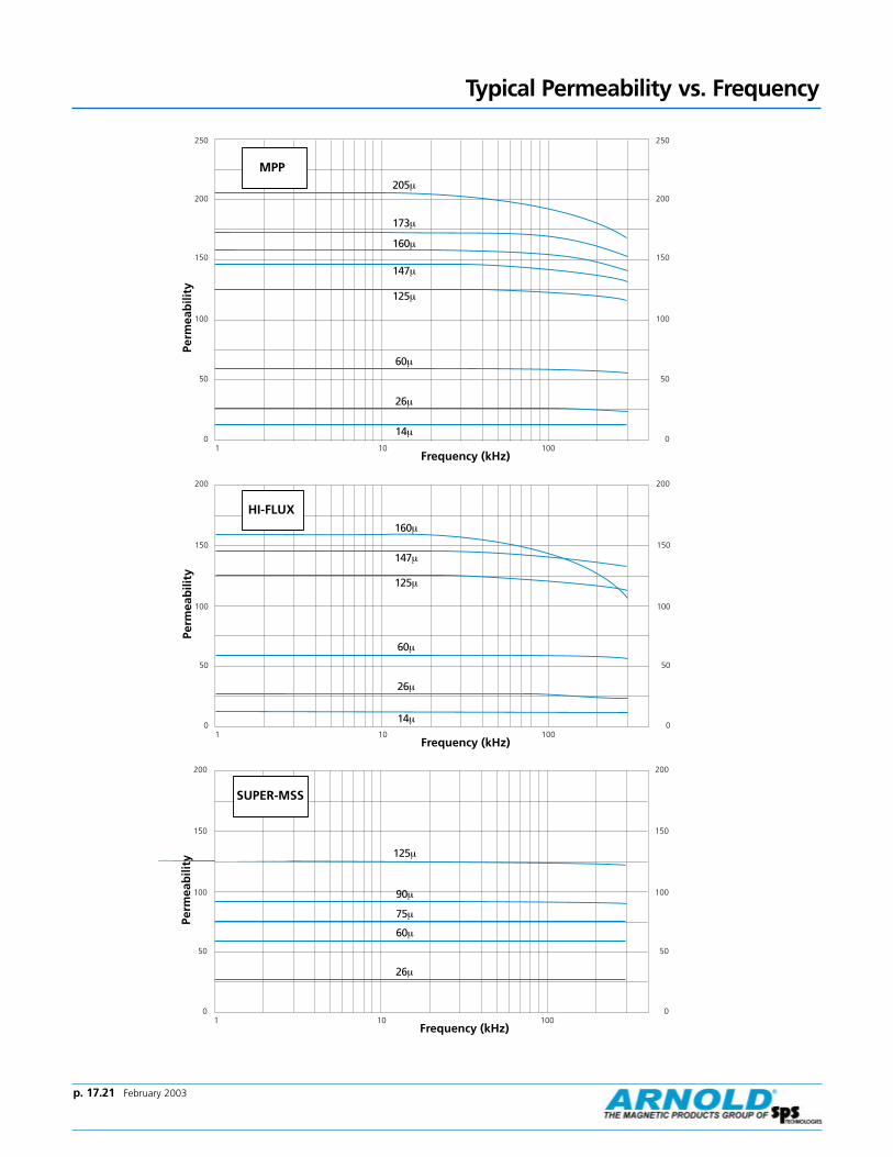
Typical Permeability vs. Frequency
HI-FLUX
10
50
100
150
200
0
50
100
150
200
10 100Frequency (kHz)
Perm
eab
ility
160µ
147µ
125µ
60µ
26µ
14µ
SUPER-MSS
10
50
100
150
200
0
50
100
150
200
10 100Frequency (kHz)
Perm
eab
ility
125µ
60µ
75µ
90µ
26µ
MPP
10
50
100
150
200
250
0
50
100
150
200
250
10 100Frequency (kHz)
Perm
eab
ility
14µ
26µ
60µ
125µ
147µ
160µ
173µ
205µ

p. 17.22 February 2003
Effective CrossSectional Area ofMagnetic Path, Ae
(Reference)
Effective CoreVolume, Ve(Reference)
Minimum Window
Area (Reference)
Approximate Weight of
Finished 125µ MPPCore
Approximate MeanLength of Turn for FullWinding (Half of I.D.
Remaining)
0.0021 in2
0.0137 cm20.317 in0.817 cm
0.000656 in3
0.010746 cm30.002827 in2
0.018241 cm2
3,600 cmil
0.000187 lbs0.085 g
0.22 in0.56 cm
Nominal Permeability
Inductance Factor, mH +/- 8%
(+/- 15% for SUPER-MSS)
for 1000 turns
Approximate Ratio ofDC Resistance to
Inductance for FullWinding (Half of I.D.Remaining), Ω/mH
Part Numbers(The finish voltage breakdown requirement does not apply.)
Molypermalloy HI-FLUX SUPER-MSS
60µ 13 11 — HF-014060-8 MS-014060-875µ 16 9.1 — — MS-014075-890µ 19 7.7 — — MS-014090-8
125µ 26 5.9 A-479026-8 HF-014125-8 MS-014125-8147µ 31 4.7 A-480031-8 HF-014147-8 —160µ 33 4.4 A-481033-8 HF-014160-8 —
173µ 36 4.0 A-482036-8 — —205µ 43 3.7 A-522043-8 — —250µ 52 2.8 A-483052-8 — —
Dimensions
Outside Diameter Inside Diameter Height
Before Coating 0.140 in 0.070 in 0.060 inNominal 3.56 mm 1.78 mm 1.52 mm
After Coating 0.148 in Max. 0.060 in Min. 0.068 in Max.(Parylene C) 3.76 mm Max. 1.52 mm Min. 1.73 mm Max.
Effective MagneticPath Length, le
(Reference)
Physical Specifications
Electrical Specifications
Heavy Film Magnet Wire Winding Data (Approximate)
Full Winding Single Layer WindingAWG (Half of I.D. Remaining) with 1 inch Leads
Turns Rdc' Ω Turns Rdc' Ω lw' in.
28 10 0.01368 9 0.0237 4.429 12 0.0208 10 0.0314 4.630 15 0.0330 11 0.0431 5.0
31 19 0.0515 13 0.0581 5.332 24 0.0774 14 0.0768 5.733 30 0.1221 16 0.105 6.1
34 38 0.1929 19 0.146 6.735 47 0.303 21 0.200 7.336 59 0.471 24 0.272 7.9
37 73 0.712 27 0.363 8.538 93 1.132 30 0.503 9.339 121 1.916 35 0.727 10
40 148 2.97 40 1.02 1141 186 4.52 44 1.37 1242 238 7.23 50 1.90 14
43 294 11.48 56 2.67 1544 344 16.16 60 3.45 16
o.d. 0.140i.d. 0.070/ht. 0.060
CORNERS:
Tumbled

Typical Molypermalloy Q vs. frequency curves at indicated inductance and distributed capacitance.
Molypermalloy Q Curveso.d. 0.140
i.d. 0.070/ht. 0.060
1
2
3
4
68
10
20
30
40
6080
100
Q
1 2 3 4 6 8 10 20 30 40 60 100 200 400 600 1000
125 µ
0.001 Hy, Cd=
6pf
Frequency-Kilohertz
1
2
3
4
68
10
20
30
40
6080
100
Q
1 2 3 4 6 8 10 20 30 40 60 100 200 400 600 1000
160 µ
0.001 Hy, Cd=
6pf
Frequency-Kilohertz
1
2
3
4
68
10
20
30
40
6080
100
Q
1 2 3 4 6 8 10 20 30 40 60 100 200 400 600 1000
205 µ
0.001 Hy, Cd=
6 pf
Frequency-Kilohertz
1
2
3
4
68
10
20
30
40
6080
100
Q
1 2 3 4 6 8 10 20 30 40 60 100 200 400 600 1000
147 µ
0.001 Hy, Cd=
5pf
Frequency-Kilohertz
1
2
3
4
68
10
20
30
40
6080
100
Q
1 2 3 4 6 8 10 20 30 40 60 100 200 400 600 1000
173 µ
0.001 Hy, Cd=
6pf
Frequency-Kilohertz
p. 17.23 February 2003

p. 17.24 February 2003
o.d. 0.155i.d. 0.087/ht. 0.100
Effective CrossSectional Area ofMagnetic Path, Ae
(Reference)
Effective CoreVolume, Ve(Reference)
Minimum Window
Area (Reference)
Approximate Weight of
Finished 125µ MPPCore
Approximate MeanLength of Turn for FullWinding (Half of I.D.
Remaining)
0.003245 in2
0.0211 cm20.370 in0.942 cm
0.001200 in3
0.019670 cm30.004902 in2
0.031624 cm2
6,241 cmil
0.000365 lbs0.166 g
0.30 in0.76 cm
Nominal Permeability
Inductance Factor, mH +/- 8%
(+/- 15% for SUPER-MSS)
for 1000 turns
Approximate Ratio ofDC Resistance to
Inductance for FullWinding (Half of I.D.Remaining), Ω/mH Molypermalloy HI-FLUX SUPER-MSS
14µ 4 32 A-467004-8 HF-015014-8 —26µ 7 15 A-468007-8 HF-015026-8 —60µ 17 6.5 A-469017-8 HF-015060-8 MS-015060-8
75µ 21 5.8 — — MS-015075-890µ 25 4.9 — — MS-015090-8
125µ 35 3.5 A-470035-8 HF-015125-8 MS-015125-8
147µ 41 2.6 A-471041-8 HF-015147-8 —160µ 45 2.5 A-472045-8 HF-015160-8 —173µ 48 2.4 A-473048-8 — —
205µ 57 2.2 A-474057-8 — —250µ 70 1.7 A-475070-8 — —
Dimensions
Outside Diameter Inside Diameter Height
Before Coating 0.155 in 0.087 in 0.100 inNominal 3.94 mm 2.21 mm 2.54 mm
After Coating 0.163 in Max. 0.079 in Min. 0.108 in Max.(Parylene C) 4.14 mm Max. 2.01 mm Min. 2.74 mm Max.
Effective MagneticPath Length, le
(Reference)
Physical Specifications
Electrical Specifications
Heavy Film Magnet Wire Winding Data (Approximate)
Full Winding Single Layer WindingAWG (Half of I.D. Remaining) with 1 inch Leads
Turns Rdc' Ω Turns Rdc' Ω lw' in.
26 11 0.01265 9 0.0184 5.427 13 0.01950 11 0.0248 5.828 17 0.0307 12 0.0342 6.3
29 21 0.0465 14 0.0458 6.830 26 0.0740 16 0.0638 7.431 33 0.1154 18 0.0869 8.0
32 40 0.1735 20 0.116 8.633 51 0.274 23 0.161 9.434 64 0.433 26 0.226 10
35 80 0.681 29 0.313 1136 100 1.059 33 0.430 1237 124 1.604 36 0.579 14
38 156 2.55 41 0.807 1539 205 4.33 47 1.18 1740 250 6.71 53 1.67 19
41 312 10.23 59 2.25 2042 401 16.40 67 3.15 2343 496 26.1 74 4.45 2544 578 36.7 80 5.76 27
CORNERS:
Tumbled
Part Numbers(The finish voltage breakdown requirement does not apply.)

Typical Molypermalloy Q vs. frequency curves at indicated inductance and distributed capacitance.
Molypermalloy Q Curves
Frequency-Kilohertz
Frequency-Kilohertz
Frequency-Kilohertz
Frequency-Kilohertz
Frequency-Kilohertz
Frequency-Kilohertz
Frequency-Kilohertz
o.d. 0.155i.d. 0.087/ht. 0.100
10 20 30 40 60 100 200 400 600 1000 2000 4000 100001
2
3
4
68
10
20
30
40
6080
100
Q
14 µ
0.001H
y, Cd=
8p
f
1
2
3
4
68
10
20
30
40
6080
100
Q
1 2 3 4 6 8 10 20 30 40 60 100 200 400 600 1000
60 µ 0.001 Hy, Cd=
7pf
1
2
3
4
68
10
20
30
40
6080
100
Q
1 2 3 4 6 8 10 20 30 40 60 100 200 400 600 1000
147 µ
0.01Hy, Cd
=7
pf
0.001 Hy, Cd=
6pf
1
2
3
4
68
10
20
30
40
6080
100
Q
10 20 30 40 60 100 200 400 600 1000 2000 4000 10000
26 µ
0.001H
y, Cd=
7p
f
1
2
3
4
68
10
20
30
40
6080
100
Q
1 2 3 4 6 8 10 20 30 40 60 100 200 400 600 1000
125 µ
0.01H
y, Cd=
8pf
0.001 Hy, Cd=
8pf
1
2
3
4
68
10
20
30
40
6080
100
Q
1 2 3 4 6 8 10 20 30 40 60 100 200 400 600 1000
160 µ
0.01Hy, Cd
=7
pf
0.001 Hy, Cd=
7pf
1
2
3
4
68
10
20
30
40
6080
100
Q
1 2 3 4 6 8 10 20 30 40 60 100 200 400 600 1000
205 µ
0.01Hy, Cd
=8
pf
l0.001
Hy, Cd=
7pf
Frequency-Kilohertz
1
2
3
4
68
10
20
30
40
6080
100
Q
1 2 3 4 6 8 10 20 30 40 60 100 200 400 600 1000
173 µ
0.01Hy, Cd
=8
pf
0.001Hy, Cd
=7
pf
p. 17.25 February 2003

p. 17.26 February 2003
o.d. 0.183i.d. 0.093/ht. 0.100
Effective CrossSectional Area ofMagnetic Path, Ae
(Reference)
Effective CoreVolume, Ve(Reference)
Minimum Window
Area (Reference)
Approximate Weight of
Finished 125µ MPPCore
Approximate MeanLength of Turn for FullWinding (Half of I.D.
Remaining)
0.00442 in2
0.0285 cm20.418 in1.061 cm
0.001837 in3
0.0302 cm30.004536 in2
0.029267 cm2
5,776 cmil
0.0007 lbs0.3 g
0.37 in0.95 cm
Nominal Permeability
Inductance Factor, mH +/- 8%
(+/- 15% forSUPER-MSS)
for 1000 turns
Approximate Ratio ofDC Resistance to
Inductance for FullWinding (Half of I.D.Remaining), Ω/mH Molypermalloy HI-FLUX SUPER-MSS
14µ 5 25 A-350005-8 HF-018014-8 —26µ 9 14 A-351009-8 HF-018026-8 —60µ 20 6.3 A-352020-8 HF-018060-8 MS-018060-8
75µ 25 5.0 — — MS-018075-890µ 30 4.2 — — MS-018090-8
125µ 42 3.0 A-353042-8 HF-018125-8 MS-018125-8
147µ 49 2.6 A-354049-8 HF-018147-8 —160µ 53 2.4 A-355053-8 HF-018160-8 —173µ 57 2.2 A-356057-8 — —
205µ 68 1.9 A-357068-8 — —250µ 83 1.5 A-358083-8 — —
Dimensions
Outside Diameter Inside Diameter Height
Before Coating 0.183 in 0.093 in 0.100 inNominal 4.65 mm 2.36 mm 2.54 mm
After Coating 0.205 in Max. 0.076 in Min. 0.130 in Max.(Parylene C) 5.21 mm Max. 1.93 mm Min. 3.30 mm Max.
Effective MagneticPath Length, le
(Reference)
Physical Specifications
Electrical Specifications
Heavy Film Magnet Wire Winding Data (Approximate)
Full Winding Single Layer WindingAWG (Half of I.D. Remaining) with 1 inch Leads
Turns Rdc' Ω Turns Rdc' Ω lw' in.
26 12 0.01535 9 0.0205 6.027 14 0.0237 10 0.0280 6.528 18 0.0373 12 0.0388 7.1
29 22 0.0566 13 0.0524 7.730 28 0.0902 15 0.0734 8.531 35 0.1406 17 0.101 9.2
32 42 0.2117 19 0.135 1033 53 0.334 22 0.188 1134 67 0.529 25 0.266 12
35 84 0.834 28 0.371 1436 104 1.297 31 0.511 1537 129 1.967 35 0.691 16
38 163 3.14 39 0.968 1839 213 5.32 45 1.42 2040 260 8.25 51 2.02 22
41 324 12.59 57 2.73 2542 417 20.2 64 3.83 2843 514 32.1 71 5.42 3044 600 45.2 77 7.03 33
Part Numbers(The finish voltage breakdown requirement does not apply.)
CORNERS:
Tumbled
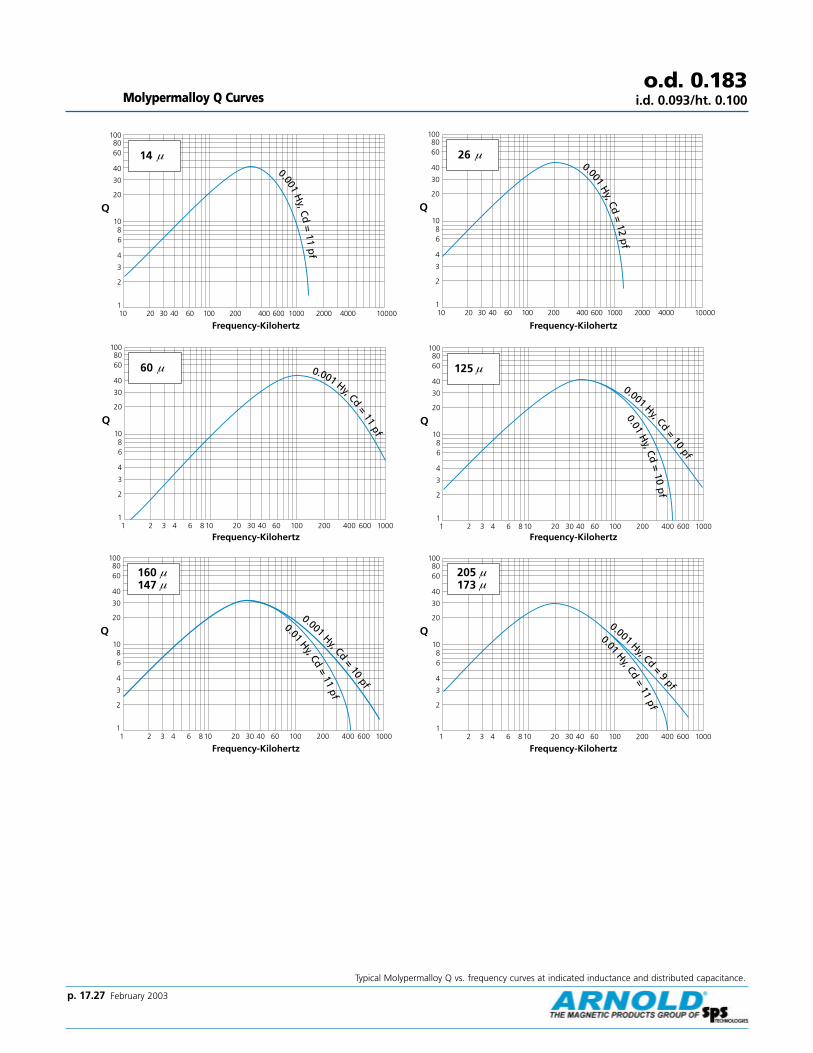
Typical Molypermalloy Q vs. frequency curves at indicated inductance and distributed capacitance.
Molypermalloy Q Curveso.d. 0.183
i.d. 0.093/ht. 0.100
Page 9
10 20 30 40 60 100 200 400 600 1000 2000 4000 100001
2
3
4
68
10
20
30
40
6080
100
Q
14 µ0.001
Hy, Cd
=11
pf
Frequency-Kilohertz
Page 9
1
2
3
4
68
10
20
30
40
6080
100
Q
1 2 3 4 6 8 10 20 30 40 60 100 200 400 600 1000
60 µ 0.001 Hy, Cd=
11pf
Frequency-Kilohertz
Page 9
1
2
3
4
68
10
20
30
40
6080
100
Q
1 2 3 4 6 8 10 20 30 40 60 100 200 400 600 1000
160 147 µµ
µ
0.01Hy, Cd
=11
pf
0.001 Hy, Cd=
10pf
Frequency-Kilohertz
Page 9
10 20 30 40 60 100 200 400 600 1000 2000 4000 100001
2
3
4
68
10
20
30
40
6080
100
Q
26 µ0.001
Hy, Cd
=12
pf
Frequency-Kilohertz
Page 9
1
2
3
4
68
10
20
30
40
6080
100
Q
1 2 3 4 6 8 10 20 30 40 60 100 200 400 600 1000
125 µ
0.01H
y, Cd=
10p
f
0.001 Hy, Cd=
10pf
Frequency-Kilohertz
Page 9
1
2
3
4
68
10
20
30
40
6080
100
Q
1 2 3 4 6 8 10 20 30 40 60 100 200 400 600 1000
205 173 µµ
µ
0.01Hy, Cd
=11
pf
0.001 Hy, Cd=
9pf
Frequency-Kilohertz
p. 17.27 February 2003

p. 17.28 February 2003
o.d. 0.250i.d. 0.110/ht. 0.110
Effective CrossSectional Area ofMagnetic Path, Ae
(Reference)
Effective CoreVolume, Ve(Reference)
Minimum Window
Area (Reference)
Approximate Weight of
Finished 125µ MPPCore
Approximate MeanLength of Turn for FullWinding (Half of I.D.
Remaining)
0.00738 in2
0.0476 cm20.536 in1.363 cm
0.003919 in3
0.064219 cm30.006362 in2
0.041043 cm2
8,100 cmil
0.0013 lbs0.6 g
0.46 in1.17 cm
Nominal Permeability
Approximate Ratio ofDC Resistance to
Inductance for FullWinding (Half of I.D.Remaining), Ω/mH
Part Numbers
Molypermalloy HI-FLUX SUPER-MSS
14µ 6 17 A-531006-8 HF-025014-8 —26µ 10 9.2 A-530010-8 HF-025026-8 —60µ 24 4.0 A-529024-8 HF-025060-8 MS-025060-8
75µ 30 3.2 — — MS-025075-890µ 36 2.7 — — MS-025090-8
125µ 52 1.9 A-520052-8 HF-025125-8 MS-025125-8
147µ 58 1.7 A-528058-8 HF-025147-8 —160µ 64 1.5 A-527064-8 HF-025160-8 —173µ 69 1.4 A-526069-8 — —
200µ — — — — —205µ 82 1.2 A-512082-8 — —250µ 100 0.97 A-525100-8 — —
300µ 120 0.81 A-521120-8 — —350µ 140 0.69 A-543140-8 — —
Dimensions
Outside Diameter Inside Diameter Height
Before Coating 0.250 in 0.110 in 0.110 inNominal 6.35 mm 2.79 mm 2.79 mm
After Coating 0.275 in Max. 0.090 in Min. 0.135 in Max.(Parylene C ) 6.99 mm Max. 2.29 mm Min. 3.43 mm Max.
Effective MagneticPath Length, le
(Reference)
Physical Specifications
Electrical Specifications
Heavy Film Magnet Wire Winding Data (Approximate)
Full Winding Single Layer WindingAWG (Half of I.D. Remaining) with 1 inch Leads
Turns Rdc' Ω Turns Rdc' Ω lw' in.
24 10 0.01038 8 0.0132 6.225 13 0.01619 10 0.0183 6.826 16 0.0255 11 0.0253 7.4
27 20 0.0392 13 0.0346 8.128 25 0.0618 14 0.0482 8.929 31 0.0937 16 0.0653 9.7
30 39 0.1493 19 0.0918 1131 48 0.233 21 0.126 1232 59 0.351 23 0.170 13
33 74 0.554 26 0.238 1434 93 0.878 30 0.337 1635 116 1.385 34 0.470 17
Full Winding AWG (Half of I.D. Remaining) Single Layer Winding
Turns Rdc' Ω Turns Rdc' Ω lw' in.
36 145 2.15 38 0.650 1937 180 3.27 42 0.880 2138 227 5.21 47 1.24 23
39 297 8.85 54 1.82 2640 363 13.74 61 2.59 2941 454 21.0 68 3.50 32
42 583 33.7 77 4.92 3643 720 53.5 85 6.98 3944 840 75.4 91 9.05 42
Inductance Factor, mH +/- 8%
(+/- 12% for SUPER-MSS)
for 1000 turns
CORNERS:
0.016 Approx.Radius Bottom,Chamfer Top

Typical Molypermalloy Q vs. frequency curves at indicated inductance and distributed capacitance.
Molypermalloy Q Curveso.d. 0.250
i.d. 0.110/ht. 0.110
Page 11
1
2
3
4
68
10
20
30
40
6080
100
Q
1 2 3 4 6 8 10 20 30 40 60 100 200 400 600 1000
14 µ0.001 Hy, Cd =
14pf
Frequency-Kilohertz Page 11
Frequency-Kilohertz
Page 11
1
2
3
4
68
10
20
30
40
6080
100
Q
1 2 3 4 6 8 10 20 30 40 60 100 200 400 600 1000
160 147 µµ
µ
0.01H
y, Cd=
14pf
0.001Hy, Cd
=13
pf
Page 11
1
2
3
4
68
10
20
30
40
6080
100
Q
1 2 3 4 6 8 10 20 30 40 60 100 200 400 600 1000
60 µ
0.01H
y, Cd
=15
pf
0.001 Hy, Cd=
14pf
Frequency-Kilohertz
Page 11
1
2
3
4
68
10
20
30
40
6080
100
Q
1 2 3 4 6 8 10 20 30 40 60 100 200 400 600 1000
26 µ 0.001 Hy, Cd =15
pf
Frequency-Kilohertz
Page 11
1
2
3
4
68
10
20
30
40
6080
100
Q
1 2 3 4 6 8 10 20 30 40 60 100 200 400 600 1000
125 µ
0.01H
y, Cd=
13p
f
0.001 Hy, Cd=
12pf
Frequency-Kilohertz
Page 11
1
2
3
4
68
10
20
30
40
6080
100
Q
1 2 3 4 6 8 10 20 30 40 60 100 200 400 600 1000
205 173 µµ
µ
0.01H
y, Cd=
14pf
0.001Hy, Cd
=13
pf
Frequency-Kilohertz
p. 17.29 February 2003

p. 17.30 February 2003
o.d. 0.260i.d. 0.105/ht. 0.100
Effective CrossSectional Area ofMagnetic Path, Ae
(Reference)
Effective CoreVolume, Ve(Reference)
Minimum Window
Area (Reference)
Approximate Weight of
Finished 125µ MPPCore
Approximate MeanLength of Turn for FullWinding (Half of I.D.
Remaining)
0.00738 in2
0.0476 cm20.537 in1.363 cm
0.003904 in3
0.063971 cm30.006362 in2
0.041043 cm2
8,100 cmil
0.0015 lbs0.7 g
0.44 in1.11 cm
Nominal Permeability
Approximate Ratio ofDC Resistance to
Inductance for FullWinding (Half of I.D.Remaining), Ω/mH
Part Numbers
Molypermalloy HI-FLUX SUPER-MSS
14µ 6.05 19 A-674006-8 HF-027014-8 —26µ 11.2 11 A-675011-8 HF-027026-8 —60µ 26 4.5 A-460026-8 HF-027060-8 MS-027060-8
75µ 32 3.7 — — MS-027075-890µ 39 3.1 — — MS-027090-8
125µ 54 2.2 A-331054-8 HF-027125-8 MS-027125-8
147µ 64 1.8 A-464064-8 HF-027147-8 —160µ 69 1.7 A-461069-8 HF-027160-8 —173µ 75 1.6 A-465075-8 — —
205µ 89 1.3 A-462089-8 — —250µ 108 1.1 A-362108-8 — —300µ 130 0.90 A-384130-8 — —350µ 151 0.77 A-406151-8 — —
Dimensions
Outside Diameter Inside Diameter Height
Before Coating 0.260 in 0.105 in 0.100 inNominal 6.60 mm 2.67 mm 2.54 mm
After Coating 0.285 in Max. 0.090 in Min. 0.125 in Max.(Parylene C) 7.24 mm Max. 2.29 mm Min. 3.18 mm Max.
Effective MagneticPath Length, le
(Reference)
Physical Specifications
Electrical Specifications
Heavy Film Magnet Wire Winding Data (Approximate)
Full Winding Single Layer WindingAWG (Half of I.D. Remaining) with 1 inch Leads
Turns Rdc' Ω Turns Rdc' Ω lw' in.
25 12 0.01516 10 0.0180 6.726 15 0.0239 11 0.0249 7.327 19 0.0368 13 0.0341 8.0
28 23 0.0579 14 0.0474 8.729 29 0.0878 16 0.0642 9.530 36 0.1399 19 0.0902 10
31 45 0.218 21 0.124 1132 55 0.329 23 0.167 1233 69 0.519 26 0.233 14
34 86 0.823 30 0.330 1535 108 1.298 34 0.461 1736 134 2.02 38 0.637 18
Full Winding AWG (Half of I.D. Remaining) Single Layer Winding
Turns Rdc' Ω Turns Rdc' Ω lw' in.
37 166 3.06 42 0.862 2038 210 4.89 47 1.21 2239 274 8.29 54 1.78 25
40 335 12.87 61 2.53 2841 419 19.65 68 3.43 3142 538 31.5 77 4.81 35
43 664 50.2 85 6.83 3844 774 70.7 91 8.85 41
Inductance Factor, mH +/- 8%
(+/- 12% for SUPER-MSS)
for 1000 turns
CORNERS:
0.016 Approx.Radius Bottom,Chamfer Top

Typical Molypermalloy Q vs. frequency curves at indicated inductance and distributed capacitance.
Molypermalloy Q Curveso.d. 0.260
i.d. 0.105/ht. 0.100
Page 13
1
2
3
4
68
10
20
30
40
6080
100
Q
1 2 3 4 6 8 10 20 30 40 60 100 200 400 600 1000
60 µ
0.01H
y, Cd
=15
pf
0.001 Hy, Cd=
14pf
Frequency-Kilohertz
Page 13
1
2
3
4
68
10
20
30
40
6080
100
Q
1 2 3 4 6 8 10 20 30 40 60 100 200 400 600 1000
147 125 µµ
µ
0.01H
y, Cd=
14p
f
0.001 Hy, Cd=
12pf
Frequency-Kilohertz
Page 13
1
2
3
4
68
10
20
30
40
6080
100
Q
1 2 3 4 6 8 10 20 30 40 60 100 200 400 600 1000
205 173 µµ
µ
0.01Hy, Cd
=13
pf
0.001 Hy, Cd=
12pf
Frequency-Kilohertz
p. 17.31 February 2003

p. 17.32 February 2003
o.d. 0.260i.d. 0.105/ht. 0.188
Effective CrossSectional Area ofMagnetic Path, Ae
(Reference)
Effective CoreVolume, Ve(Reference)
Minimum Window
Area (Reference)
Approximate Weight of
Finished 125µ MPPCore
Approximate MeanLength of Turn for FullWinding (Half of I.D.
Remaining)
0.01426 in2
0.0920 cm20.537 in1.363 cm
0.007443 in3
0.1254 cm30.005945 in2
0.038353 cm2
7,569 cmil
0.0024 lbs1.1 g
0.62 in1.57 cm
Nominal Permeability
Approximate Ratio ofDC Resistance to
Inductance for FullWinding (Half of I.D.Remaining), Ω/mH
Part Numbers
Molypermalloy HI-FLUX SUPER-MSS
14µ 12 14 A-630012-8 HF-026014-8 —26µ 21.4 8.0 A-639021-8 HF-026026-8 —60µ 50 3.4 A-135050-8 HF-026060-8 MS-026060-8
75µ 62 2.7 — — MS-026075-890µ 74 2.3 — — MS-026090-8
125µ 103 1.6 A-134103-8 HF-026125-8 MS-026125-8
147µ 122 1.4 A-224122-8 HF-026147-8 —160µ 132 1.3 A-638132-8 HF-026160-8 —173µ 144 1.2 A-222144-8 — —
205µ 170 0.99 A-200170-8 — —250µ 206 0.82 A-363206-8 — —300µ 247 0.68 A-385247-8 — —350µ 296 0.57 A-337296-8 — —
Dimensions
Outside Diameter Inside Diameter Height
Before Coating 260 in 0.105 in 0.188 inNominal 6.60 mm 2.67 mm 4.78 mm
After Coating 0.288 in Max. 0.087 in Min. 0.218 in Max.(Parylene C) 7.32 mm Max. 2.21 mm Min. 5.54 mm Max.
Effective MagneticPath Length, le
(Reference)
Physical Specifications
Electrical Specifications
Heavy Film Magnet Wire Winding Data (Approximate)
Full Winding Single Layer WindingAWG (Half of I.D. Remaining) with 1 inch Leads
Turns Rdc' Ω Turns Rdc' Ω lw' in.
25 12 0.0206 9 0.0223 8.326 15 0.0326 11 0.0312 9.127 19 0.0503 12 0.0431 10
28 23 0.0795 14 0.0605 1129 29 0.1208 16 0.0826 1230 36 0.1928 18 0.117 14
31 45 0.301 20 0.162 1532 55 0.455 22 0.220 1633 69 0.719 25 0.309 18
34 86 1.142 29 0.440 2035 108 1.804 32 0.617 2236 134 2.81 36 0.857 25
Full Winding AWG (Half of I.D. Remaining) Single Layer Winding
Turns Rdc' Ω Turns Rdc' Ω lw' in.
37 166 4.27 40 1.17 2738 210 6.82 45 1.64 3039 274 11.60 52 2.42 34
40 335 18.02 59 3.46 3941 419 27.5 66 4.70 4342 538 44.2 74 6.62 48
43 664 70.4 82 9.42 5344 774 99.3 88 12.2 57
Inductance Factor, mH +/- 8%
(+/- 12% for SUPER-MSS)
for 1000 turns
CORNERS:
0.016 Approx.Radius Bottom,Chamfer Top

Typical Molypermalloy Q vs. frequency curves at indicated inductance and distributed capacitance.
Molypermalloy Q Curveso.d. 0.260
i.d. 0.105/ht. 0.188
Page 13
1
2
3
4
68
10
20
30
40
6080
100
Q
1 2 3 4 6 8 10 20 30 40 60 100 200 400 600 1000
60 µ
0.01H
y, Cd
=21
pf
0.001Hy, Cd
=24
pf
Frequency-Kilohertz
Page 13
1
2
3
4
68
10
20
30
40
6080
100
Q
1 2 3 4 6 8 10 20 30 40 60 100 200 400 600 1000
147 125 µµ
µ
0.01H
y, Cd=
21p
f
0.001 Hy, Cd=
18pf
Frequency-Kilohertz
Page 13
1
2
3
4
68
10
20
30
40
6080
100
F Kil h t
Q
1 2 3 4 6 8 10 20 30 40 60 100 200 400 600 1000
205 173 µµ
µ
0.01Hy, Cd
=13
pf
0.001 Hy, Cd=
12pf
Frequency-Kilohertz
p. 17.33 February 2003

p. 17.34 February 2003
o.d. 0.277i.d. 0.156/ht. 0.200
Effective CrossSectional Area ofMagnetic Path, Ae
(Reference)
Effective CoreVolume, Ve(Reference)
Minimum Window
Area (Reference)
Approximate Weight of
Finished 125µ MPPCore
Approximate MeanLength of Turn for FullWinding (Half of I.D.
Remaining)
0.01162 in2
0.07497 cm20.662 in1.682 cm
0.007693 in3
0.126069 cm30.01453 in2
0.09372 cm2
18,496 cmil
0.0026 lbs1.2 g
0.63 in1.60 cm
Nominal Permeability
Approximate Ratio ofDC Resistance to
Inductance for FullWinding (Half of I.D.Remaining), Ω/mH
Part Numbers
Molypermalloy HI-FLUX SUPER-MSS
14µ 8 7.9 A-541008-8 HF-028014-8 —26µ 14 4.5 A-540014-8 HF-028026-8 —60µ 33 1.92 A-539033-8 HF-028060-8 MS-028060-8
75µ 42 1.53 — — MS-028075-890µ 50 1.29 — — MS-028090-8
125µ 70 0.92 A-538070-8 HF-028125-8 MS-028125-8
147µ 81 0.78 A-537081-8 HF-028147-8 —160µ 89 0.72 A-536089-8 HF-028160-8 —173µ 95 0.67 A-535095-8 — —
205µ 113 0.56 A-453113-8 — —250µ 138 0.46 A-534138-8 — —300µ 166 0.38 A-533166-8 — —350µ 194 0.33 A-532194-8 — —
Dimensions
Outside Diameter Inside Diameter Height
Before Coating 0.277 in 0.156 in 0.200 inNominal 7.04 mm 3.96 mm 5.08 mm
After Coating 0.302 in Max. 0.136 in Min. 0.225 in Max.(Parylene C) 7.67 mm Max. 3.45 mm Min. 5.72 mm Max.
Effective MagneticPath Length, le
(Reference)
Physical Specifications
Electrical Specifications
Heavy Film Magnet Wire Winding Data (Approximate)
Full Winding Single Layer WindingAWG (Half of I.D. Remaining) with 1 inch Leads
Turns Rdc' Ω Turns Rdc' Ω lw' in.
21 11 0.00798 9 0.00902 8.522 14 0.01260 11 0.0126 9.323 18 0.01942 12 0.0174 10
24 22 0.0304 14 0.0242 1125 27 0.0473 16 0.0338 1326 34 0.0744 18 0.0472 14
27 43 0.1144 21 0.0651 1528 53 0.1805 23 0.0915 1729 66 0.274 26 0.125 18
30 83 0.436 29 0.177 2131 103 0.681 33 0.244 2232 126 1.026 36 0.331 25
33 158 1.623 41 0.466 2734 198 2.57 46 0.664 3135 249 4.06 52 0.932 34
Full Winding AWG (Half of I.D. Remaining) Single Layer Winding
Turns Rdc' Ω Turns Rdc' Ω lw' in.
36 310 6.33 58 1.29 3737 383 9.62 65 1.76 4138 485 15.35 73 2.48 46
39 634 26.1 83 3.65 5240 774 40.5 93 5.22 5841 968 61.9 104 7.10 64.4
42 1243 99.5 117 9.99 7243 1535 158.3 130 14.2 8044 1790 223.0 140 18.4 85
Inductance Factor, mH +/- 8%
(+/- 12% for SUPER-MSS)
for 1000 turns
CORNERS:
0.016 Approx.Radius Bottom,Chamfer Top

Typical Molypermalloy Q vs. frequency curves at indicated inductance and distributed capacitance.
Molypermalloy Q Curveso.d. 0.277
i.d. 0.156/ht. 0.200
Q
1
2
3
4
68
10
20
30
40
6080
100
1000
14 µµ0.001
Hy, Cd
=16
pf
0.01H
y, Cd=
17p
f
1 2 3 4 6 8 10 20 30 40 60 100 200 400 600
Frequency-Kilohertz
Q
1
2
3
4
68
10
20
30
40
6080
100
1000
60 µµ 0.001Hy, Cd
=16
pf
0.1H
y, Cd
=19
pf
0.01H
y, Cd
=17
pf
Page 15
1 2 3 4 6 8 10 20 30 40 60 100 200 400 600
Frequency-Kilohertz
160 µ
1
2
3
4
68
10
20
30
40
6080
100
Q
1000
µ147 µµ
0.001Hy, Cd
=15
pf
0.1H
y, Cd
=18
pf
0.01H
y, Cd=
16pf
Page 15
1 2 3 4 6 8 10 20 30 40 60 100 200 400 600
Frequency-Kilohertz
26 µ
1
2
3
4
68
10
20
30
40
6080
100
Frequency-Kilohertz
Q
1000
µ 0.001H
y, Cd=
17pf
0.01H
y, Cd
=18
pf
1 2 3 4 6 8 10 20 30 40 60 100 200 400 600
Frequency-Kilohertz
125 µ
1
2
3
4
68
10
20
30
40
6080
100
Q
1000
µ
0.1H
y, Cd
=16
pf
0.001Hy, Cd
=14
pf
0.01H
y, Cd=
15p
f
1 2 3 4 6 8 10 20 30 40 60 100 200 400 600Frequency-Kilohertz
1 2 3 4 6 8 10 20 30 40 60 100 200 400 600
0.01H
y, Cd=
16p
f
0.1H
y, Cd
=17
pf
0.001Hy, Cd
=14
pf
205 173 µ
1
2
3
4
68
10
20
30
40
6080
100
Q
1000
µµ
Frequency-Kilohertz
p. 17.35 February 2003
p. 17.36 February 2003
o.d. 0.310i.d. 0.156/ht. 0.125
Effective CrossSectional Area ofMagnetic Path, Ae
(Reference)
Effective CoreVolume, Ve(Reference)
Minimum Window
Area (Reference)
Approximate Weight of
Finished 125µ MPPCore
Approximate MeanLength of Turn for FullWinding (Half of I.D.
Remaining)
0.00953 in2
0.0615 cm20.704 in1.787 cm
0.00671 in3
0.1099 cm30.01431 in2
0.09235 cm2
18,225 cmil
0.0022 lbs1.0 g
0.49 in1.25 cm
Nominal Permeability
Approximate Ratio ofDC Resistance to
Inductance for FullWinding (Half of I.D.Remaining), Ω/mH
Part Numbers
Molypermalloy HI-FLUX SUPER-MSS
14µ 6 8.4 A-340006-8 HF-031014-8 —26µ 11 4.6 A-339011-8 HF-031026-8 —60µ 25 2.0 A-138025-8 HF-031060-8 MS-031060-8
75µ 31 1.6 — — MS-031075-890µ 37 1.4 — — MS-031090-8
125µ 52 0.97 A-137052-8 HF-031125-8 MS-031125-8
147µ 62 0.81 A-225062-8 HF-031147-8 —160µ 66 0.76 A-338066-8 HF-031160-8 —173µ 73 0.68 A-223073-8 — —
205µ 86 0.59 A-201086-8 — —250µ 104 0.48 A-364104-8 — —300µ 124 0.41 A-386124-8 — —350µ 145 0.35 A-407145-8 — —
Dimensions
Outside Diameter Inside Diameter Height
Before Coating 0.310 in 0.156 in 0.125 inNominal 7.87 mm 3.96 mm 3.18 mm
After Coating 0.335 in Max. 0.135 in Min. 0.150 in Max.(Parylene C) 8.51 mm Max. 3.43 mm Min. 3.81 mm Max.
Effective MagneticPath Length, le
(Reference)
Physical Specifications
Electrical Specifications
Heavy Film Magnet Wire Winding Data (Approximate)
Full Winding Single Layer WindingAWG (Half of I.D. Remaining) with 1 inch Leads
Turns Rdc' Ω Turns Rdc' Ω lw' in.
21 12 0.00651 9 0.00780 7.322 14 0.01027 11 0.0108 8.023 18 0.01580 12 0.0148 8.8
24 22 0.0247 14 0.0206 9.625 28 0.0384 16 0.0285 1126 35 0.0602 18 0.0397 12
27 43 0.0926 20 0.0545 1328 54 0.1457 23 0.0762 1429 66 0.221 26 0.104 15
30 83 0.351 29 0.146 1731 103 0.547 33 0.201 1932 126 0.824 36 0.272 20
33 158 1.302 41 0.382 2234 198 2.06 46 0.543 2535 248 3.25 52 0.760 28
Full Winding AWG (Half of I.D. Remaining) Single Layer Winding
Turns Rdc' Ω Turns Rdc' Ω lw' in.
36 309 5.06 58 1.05 3037 381 7.68 64 1.43 3438 482 12.25 72 2.01 37
39 630 20.8 82 2.96 4240 770 32.3 93 4.22 4741 961 49.3 103 5.73 52
42 1234 79.1 116 8.05 5843 1525 125.9 129 11.4 6444 1778 177.4 139 14.8 69
Inductance Factor, mH +/- 8%
(+/- 12% for SUPER-MSS)
for 1000 turns
CORNERS:
0.016 Approx.Radius Bottom,Chamfer Top

Typical Molypermalloy Q vs. frequency curves at indicated inductance and distributed capacitance.
Molypermalloy Q Curveso.d. 0.310
i.d. 0.156/ht. 0.125
1
2
3
4
68
10
20
30
40
6080
100
Q
1 2 3 4 6 8 10 20 30 40 60 100 200 400 600 1000
14 µµ 0.001 Hy, Cd=
15pf
0.01H
y, Cd
=16
pf
Frequency-Kilohertz
1
2
3
4
68
10
20
30
40
6080
100
Q
1 2 3 4 6 8 10 20 30 40 60 100 200 400 600 1000
60 µµ 0.001 Hy, Cd=
15pf
0.01H
y, Cd
=16
pf
Frequency-Kilohertz
160 µ
1
2
3
4
68
10
20
30
40
6080
100
Q
1 2 3 4 6 8 10 20 30 40 60 100 200 400 600 1000
µ147 µµ
0.001 Hy, Cd=
12pf
0.01H
y, Cd=
15p
f
0.1H
y, Cd=
14p
f
Frequency-Kilohertz
20
1
2
3
4
68
10
30
40
6080
100
Q
1 2 3 4 6 8 10 20 30 40 60 100 200 400 600 1000
26 µµ0.00 1Hy, Cd
=13
pf0.01H
y, Cd
=14
pf
Frequency-Kilohertz
1
2
3
4
68
10
20
30
40
6080
100
Q
1 2 3 4 6 8 10 20 30 40 60 100 200 400 600 1000
125 µµ
0.001Hy, Cd
=13
pf
0.01Hy, Cd
=14
pf
0.1H
y, Cd
=15
pf
Frequency-Kilohertz
205 µ
1
2
3
4
68
10
20
30
40
6080
100
Q
1 2 3 4 6 8 10 20 30 40 60 100 200 400 600 1000
µ173 µ
µ
0.001Hy, Cd
=12
pf
0.01Hy, Cd
=13
pf
0.1H
y, Cd=
14p
f
Frequency-Kilohertz
p. 17.37 February 2003
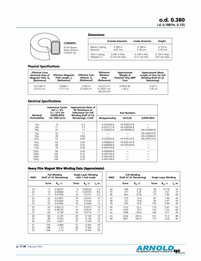
p. 17.38 February 2003
Full Winding Single Layer WindingAWG (Half of I.D. Remaining) with 1 inch Leads
Turns Rdc' Ω Turns Rdc' Ω lw' in.
19 11 0.00437 9 0.00529 7.920 14 0.00680 11 0.00729 8.621 17 0.01058 12 0.0101 9.5
22 22 0.01667 14 0.0141 1023 27 0.02560 16 0.0193 1124 33 0.03990 18 0.0268 13
25 42 0.06210 21 0.0372 1426 52 0.09730 23 0.0519 1527 64 0.149 26 0.0714 17
28 80 0.235 29 0.100 1829 98 0.356 33 0.136 2030 124 0.567 37 0.193 22
31 154 0.884 41 0.266 2432 188 1.33 46 0.360 2733 236 2.10 51 0.505 30
Heavy Film Magnet Wire Winding Data (Approximate)
o.d. 0.380i.d. 0.188/ht. 0.125
Effective CrossSectional Area ofMagnetic Path, Ae
(Reference)
Effective CoreVolume, Ve(Reference)
Minimum Window
Area (Reference)
Approximate Weight of
Finished 125µ MPPCore
Approximate MeanLength of Turn for FullWinding (Half of I.D.
Remaining)
0.01166 in2
0.0752 cm20.858 in2.177 cm
.0100 in3
0.1639 cm30.02217 in2
0.14301 cm2
28,224 cmil
0.0032 lbs1.45 g
0.53 in1.35 cm
Nominal Permeability
Approximate Ratio ofDC Resistance to
Inductance for FullWinding (Half of I.D.Remaining), Ω/mH
Part Numbers
Molypermalloy HI-FLUX SUPER-MSS
14µ 6 6.2 A-502006-8 HF-039014-8 —26µ 11 3.3 A-501011-8 HF-039026-8 —60µ 25 1.5 A-500025-8 HF-039060-8 MS-039060-8
75µ 32 1.1 — — MS-039075-890µ 38 0.96 — — MS-039090-8
125µ 53 0.69 A-250053-8 HF-039125-8 MS-039125-8
147µ 63 0.59 A-499063-8 HF-039147-8 —160µ 68 0.54 A-498068-8 HF-039160-8 —173µ 74 0.50 A-497074-8 — —
205µ 84 0.44 A-496084-8 — —250µ 106 0.35 A-495106-8 — —300µ 128 0.29 A-494128-8 — —350µ 149 0.25 A-493149-8 — —
Dimensions
Outside Diameter Inside Diameter Height
Before Coating 0.380 in 0.188 in 0.125 inNominal 9.65 mm 4.78 mm 3.18 mm
After Coating 0.405 in Max. 0.168 in Min. 0.150 in Max.(Parylene C) 10.29 mm Max. 4.27 mm Min. 3.81 mm Max.
Effective MagneticPath Length, le
(Reference)
Physical Specifications
Electrical Specifications
Heavy Film Magnet Wire Winding Data (Approximate)
Full Winding AWG (Half of I.D. Remaining) Single Layer Winding
Turns Rdc' Ω Turns Rdc' Ω lw' in.
34 296 3.33 58 0.719 3335 371 5.25 65 1.01 3736 462 8.18 73 1.40 40
37 570 12.4 81 1.90 4538 722 19.8 90 2.67 5039 943 33.6 103 3.94 56
40 1152 52.2 116 5.62 6341 1439 79.7 129 7.63 6942 1848 128.0 146 10.7 78
43 2282 203.0 161 15.3 8644 2661 287.0 173 19.8 92
Inductance Factor, mH +/- 8%
(+/- 12% for SUPER-MSS)
for 1000 turns
CORNERS:
0.016 Approx.Radius Bottom,Chamfer Top

o.d. 0.380i.d. 0.188/ht. 0.125
205 µ.345" HT.
1
2
3
4
68
10
20
30
40
6080
100
Q
1 2 3 4 6 8 10 20 30 40 60 100 200 400 600 1000
µ14 µµ 0.001Hy, Cd
=16
pf
0.01 Hy, Cd=
16p
f
Typical Molypermalloy Q vs. frequency curves at indicated inductance and distributed capacitance.
Molypermalloy Q Curves
Frequency-Kilohertz
1
2
3
4
68
10
20
30
40
6080
100
Q
1 2 3 4 6 8 10 20 30 40 60 100 200 400 600 1000
60 µµ0.001
Hy, Cd=
15pf
0.01Hy, Cd
=16
pf
0.1 Hy, Cd=
17pf
Frequency-Kilohertz
1
2
3
4
68
10
20
30
40
6080
100
Q
1 2 3 4 6 8 10 20 30 40 60 100 200 400 600 1000
µ160 µµ147 µµ
0.001Hy, Cd
=15
pf
0.01H
y, Cd=
17pf
0.1H
y, Cd=
17p
f
Frequency-Kilohertz
205 µ.345" HT.
1
2
3
4
68
10
20
30
40
6080
100
Q
1 2 3 4 6 8 10 20 30 40 60 100 200 400 600 1000
µ26 µµ0.001
Hy, Cd=
16pf
0.01Hy, Cd
=17
pf
Frequency-Kilohertz
205 µ.345" HT.
1
2
3
4
68
10
20
30
40
6080
100
Q
1 2 3 4 6 8 10 20 30 40 60 100 200 400 600 1000
µ125 µµ 0.1 Hy, Cd=
15pf
0.001Hy, Cd
=14
pf
0.01Hy, Cd
=15
pf
Frequency-Kilohertz
200 µµ173 µµ
0.1H
y, Cd=
17pf
0.01 Hy, Cd = 15 pf
1
2
3
4
68
10
20
30
40
6080
100
Q
0.1 .2 .3 .4 .6 .8 1 2 3 4 20 30 40 60 1006 8 10
Frequency-Kilohertz
p. 17.39 February 2003
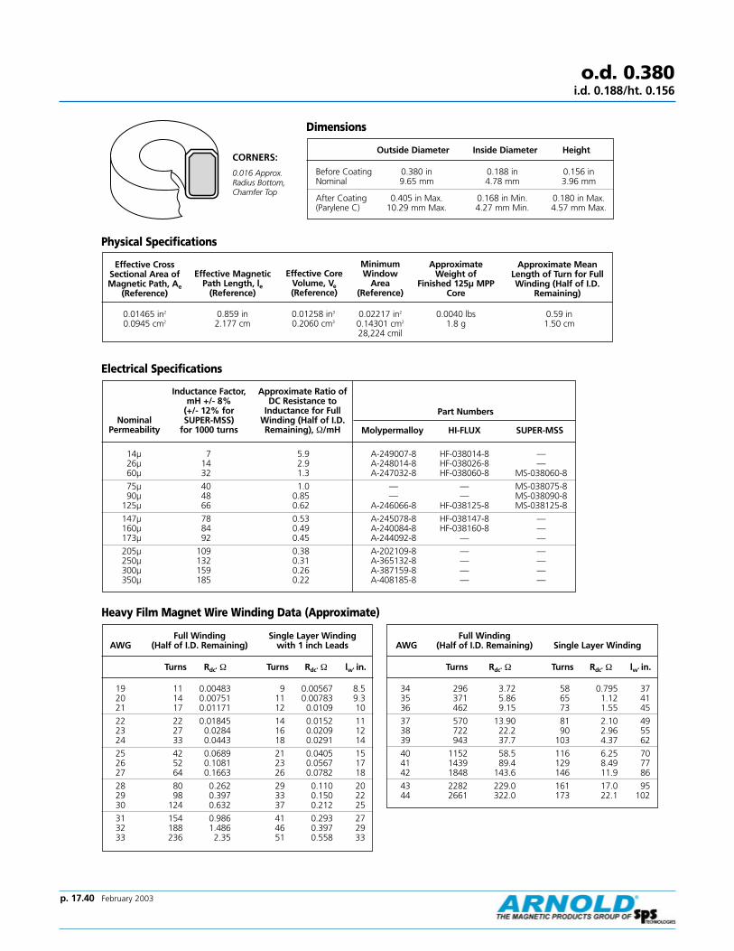
p. 17.40 February 2003
o.d. 0.380i.d. 0.188/ht. 0.156
Effective CrossSectional Area ofMagnetic Path, Ae
(Reference)
Minimum Window
Area (Reference)
Approximate Weight of
Finished 125µ MPPCore
Approximate MeanLength of Turn for FullWinding (Half of I.D.
Remaining)
0.01465 in2
0.0945 cm20.859 in2.177 cm
0.01258 in3
0.2060 cm30.02217 in2
0.14301 cm2
28,224 cmil
0.0040 lbs1.8 g
0.59 in1.50 cm
Nominal Permeability
Approximate Ratio ofDC Resistance to
Inductance for FullWinding (Half of I.D.Remaining), Ω/mH
Part Numbers
Molypermalloy HI-FLUX SUPER-MSS
14µ 7 5.9 A-249007-8 HF-038014-8 —26µ 14 2.9 A-248014-8 HF-038026-8 —60µ 32 1.3 A-247032-8 HF-038060-8 MS-038060-8
75µ 40 1.0 — — MS-038075-890µ 48 0.85 — — MS-038090-8
125µ 66 0.62 A-246066-8 HF-038125-8 MS-038125-8
147µ 78 0.53 A-245078-8 HF-038147-8 —160µ 84 0.49 A-240084-8 HF-038160-8 —173µ 92 0.45 A-244092-8 — —
205µ 109 0.38 A-202109-8 — —250µ 132 0.31 A-365132-8 — —300µ 159 0.26 A-387159-8 — —350µ 185 0.22 A-408185-8 — —
Dimensions
Outside Diameter Inside Diameter Height
Before Coating 0.380 in 0.188 in 0.156 inNominal 9.65 mm 4.78 mm 3.96 mm
After Coating 0.405 in Max. 0.168 in Min. 0.180 in Max.(Parylene C) 10.29 mm Max. 4.27 mm Min. 4.57 mm Max.
Effective MagneticPath Length, le
(Reference)
Physical Specifications
Electrical Specifications
Heavy Film Magnet Wire Winding Data (Approximate)
Full Winding Single Layer WindingAWG (Half of I.D. Remaining) with 1 inch Leads
Turns Rdc' Ω Turns Rdc' Ω lw' in.
19 11 0.00483 9 0.00567 8.520 14 0.00751 11 0.00783 9.321 17 0.01171 12 0.0109 10
22 22 0.01845 14 0.0152 1123 27 0.0284 16 0.0209 1224 33 0.0443 18 0.0291 14
25 42 0.0689 21 0.0405 1526 52 0.1081 23 0.0567 1727 64 0.1663 26 0.0782 18
28 80 0.262 29 0.110 2029 98 0.397 33 0.150 2230 124 0.632 37 0.212 25
31 154 0.986 41 0.293 2732 188 1.486 46 0.397 2933 236 2.35 51 0.558 33
Full Winding AWG (Half of I.D. Remaining) Single Layer Winding
Turns Rdc' Ω Turns Rdc' Ω lw' in.
34 296 3.72 58 0.795 3735 371 5.86 65 1.12 4136 462 9.15 73 1.55 45
37 570 13.90 81 2.10 4938 722 22.2 90 2.96 5539 943 37.7 103 4.37 62
40 1152 58.5 116 6.25 7041 1439 89.4 129 8.49 7742 1848 143.6 146 11.9 86
43 2282 229.0 161 17.0 9544 2661 322.0 173 22.1 102
Inductance Factor, mH +/- 8%
(+/- 12% for SUPER-MSS)
for 1000 turns
CORNERS:
0.016 Approx.Radius Bottom,Chamfer Top
Effective CoreVolume, Ve(Reference)

Typical Molypermalloy Q vs. frequency curves at indicated inductance and distributed capacitance.
Molypermalloy Q Curveso.d. 0.380
i.d. 0.188/ht. 0.156
1
2
3
4
68
10
20
30
40
6080
100
Q
1 2 3 4 6 8 10 20 30 40 60 100 200 400 600 1000
14 µ
0.001Hy, Cd
=19
pf
0.01H
y, Cd=
20p
f
Frequency-Kilohertz
1
2
3
4
68
10
20
30
40
6080
100
Q
1 2 3 4 6 8 10 20 30 40 60 100 200 400 600 1000
60 µ
0.1H
y, Cd
=17
pf
0.01H
y, Cd=
16p
f
0.001Hy, Cd
=15
pf
Frequency-Kilohertz
1
2
3
4
68
10
20
30
40
6080
100
1 2 3 4 6 8 10 20 30 40 60 100 200 400 600 1000
160 µµ147 µµ
0.1H
y, Cd=
17p
f0.01
Hy, Cd
=16
pf
0.001 Hy, Cd=
15pf
Frequency-Kilohertz
1
2
3
4
68
10
20
30
40
6080
100
Q
1 2 3 4 6 8 10 20 30 40 60 100 200 400 600 1000
26 µ 0.01H
y, Cd=
18p
f0.001
Hy, Cd=
17pf
Frequency-Kilohertz
1
2
3
4
68
10
20
30
40
6080
100
Q
1 2 3 4 6 8 10 20 30 40 60 100 200 400 600 1000
125 µ
0.1H
y, Cd
=19
pf
0.01H
y, Cd=
18p
f
0.001Hy, Cd
=14
pf
Frequency-Kilohertz
205 µµ173 µµ
1
2
3
4
68
10
20
30
40
6080
100
Q
.2 .3 .4 .6 .8 1 2 3 4 20 30 40 60 1006 8 100.1
0.1H
y, Cd=
18pf
0.01 Hy, Cd = 17 pf
Frequency-Kilohertz
p. 17.41 February 2003
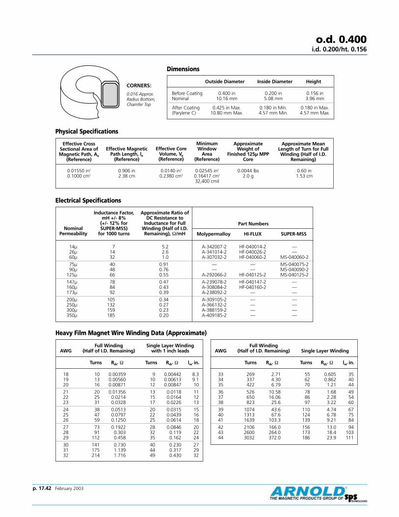
p. 17.42 February 2003
o.d. 0.400i.d. 0.200/ht. 0.156
Effective CrossSectional Area ofMagnetic Path, Ae
(Reference)
Effective CoreVolume, Ve(Reference)
Minimum Window
Area (Reference)
Approximate Weight of
Finished 125µ MPPCore
Approximate MeanLength of Turn for FullWinding (Half of I.D.
Remaining)
0.01550 in2
0.1000 cm20.906 in2.38 cm
0.0140 in3
0.2380 cm30.02545 in2
0.16417 cm2
32,400 cmil
0.0044 lbs2.0 g
0.60 in1.53 cm
Nominal Permeability
Approximate Ratio ofDC Resistance to
Inductance for FullWinding (Half of I.D.Remaining), Ω/mH
Part Numbers
Molypermalloy HI-FLUX SUPER-MSS
14µ 7 5.2 A-342007-2 HF-040014-2 —26µ 14 2.6 A-341014-2 HF-040026-2 —60µ 32 1.0 A-307032-2 HF-040060-2 MS-040060-2
75µ 40 0.91 — — MS-040075-290µ 48 0.76 — — MS-040090-2
125µ 66 0.55 A-292066-2 HF-040125-2 MS-040125-2
147µ 78 0.47 A-239078-2 HF-040147-2 —160µ 84 0.43 A-308084-2 HF-040160-2 —173µ 92 0.39 A-238092-2 — —
200µ 105 0.34 A-309105-2 — —250µ 132 0.27 A-366132-2 — —300µ 159 0.23 A-388159-2 — —350µ 185 0.20 A-409185-2 — —
Dimensions
Outside Diameter Inside Diameter Height
Before Coating 0.400 in 0.200 in 0.156 inNominal 10.16 mm 5.08 mm 3.96 mm
After Coating 0.425 in Max. 0.180 in Min. 0.180 in Max.(Parylene C) 10.80 mm Max. 4.57 mm Min. 4.57 mm Max.
Effective MagneticPath Length, le
(Reference)
Physical Specifications
Electrical Specifications
Heavy Film Magnet Wire Winding Data (Approximate)
Full Winding Single Layer WindingAWG (Half of I.D. Remaining) with 1 inch leads
Turns Rdc' Ω Turns Rdc' Ω lw' in.
18 10 0.00359 9 0.00442 8.319 13 0.00560 10 0.00613 9.120 16 0.00871 12 0.00847 10
21 20 0.01356 13 0.0118 1122 25 0.0214 15 0.0164 1223 31 0.0328 17 0.0226 13
24 38 0.0513 20 0.0315 1525 47 0.0797 22 0.0439 1626 59 0.1250 25 0.0614 18
27 73 0.1922 28 0.0846 2028 91 0.303 32 0.119 2229 112 0.458 35 0.162 24
30 141 0.730 40 0.230 2731 175 1.139 44 0.317 2932 214 1.716 49 0.430 32
Full Winding AWG (Half of I.D. Remaining) Single Layer Winding
Turns Rdc' Ω Turns Rdc' Ω lw' in.
33 269 2.71 55 0.605 3534 337 4.30 62 0.862 4035 422 6.79 70 1.21 44
36 526 10.58 78 1.68 4937 650 16.06 86 2.28 5438 823 25.6 97 3.22 60
39 1074 43.6 110 4.74 6740 1313 67.6 124 6.78 7541 1639 103.3 139 9.21 84
42 2106 166.0 156 13.0 9443 2600 264.0 173 18.4 10344 3032 372.0 186 23.9 111
Inductance Factor, mH +/- 8%
(+/- 12% for SUPER-MSS)
for 1000 turns
CORNERS:
0.016 Approx.Radius Bottom,Chamfer Top

Typical Molypermalloy Q vs. frequency curves at indicated inductance and distributed capacitance.
Page 23
60 µ
1
2
3
4
68
10
20
30
40
6080
100
Q
1 2 3 4 6 8 10 20 30 40 60 100 200 400 600 10000.1
Hy, C
d=
20p
f0.01
Hy, Cd
=18
pf
0.001Hy, Cd
=17
pf
Molypermalloy Q Curves
Frequency-Kilohertz
Frequency-Kilohertz
Frequency-Kilohertz
Frequency-Kilohertz
Frequency-Kilohertz
Frequency-Kilohertz
o.d. 0.400i.d. 0.200/ht. 0.156
Page 23
14 µ
1
2
3
4
68
10
20
30
40
6080
100
Q
1 2 3 4 6 8 10 20 30 40 60 100 200 400 600 1000
0.01H
y, Cd
=18
pf
0.001 Hy, Cd=
17pf
Page 23
1
2
3
4
68
10
20
30
40
6080
100
Q
160 µµ147 µµ
0.1 .2 .3 .4 .6 .8 1 2 3 4 20 30 40 60 1006 8 10
0.1H
y, Cd=
20pf
0.01 Hy, Cd = 19
pf
Page 23
26 µ
1
2
3
4
68
10
20
30
40
6080
100
Q
1 2 3 4 6 8 10 20 30 40 60 100 200 400 600 1000
0.1H
y, Cd=
19p
f0.01
Hy, Cd
=20
pf
0.001 Hy, Cd=
15pf
Page 23
125 µ
1
2
3
4
68
10
20
30
40
6080
100
Q
0.1 .2 .3 .4 .6 .8 1 2 3 4 20 30 40 60 1006 8 10
0.1 Hy, Cd=
18pf
0.01Hy, Cd = 17 pf
Page 23
1
2
3
4
68
10
20
30
40
6080
100
Q
200µ173µ
0.1 .2 .3 .4 .6 .8 1 2 3 4 20 30 40 60 1006 8 10
0.1 Hy, Cd=
19pf
0.01 Hy, Cd= 18 pf
p. 17.43 February 2003

p. 17.44 February 2003
o.d. 0.440i.d. 0.250/ht. 0.156
Effective CrossSectional Area ofMagnetic Path, Ae
(Reference)
Effective CoreVolume, Ve(Reference)
Minimum Window
Area (Reference)
Approximate Weight of
Finished 125µ MPPCore
Approximate MeanLength of Turn for FullWinding (Half of I.D.
Remaining)
0.01403 in2
0.0906 cm21.08 in2.69 cm
0.01515 in3
0.2437 cm30.04227 in2
0.27273 cm2
53,824 cmil
0.0044 lbs2.0 g
0.60 in1.52 cm
Nominal Permeability
Approximate Ratio ofDC Resistance to
Inductance for FullWinding (Half of I.D.Remaining), Ω/mH
Part Numbers
Molypermalloy HI-FLUX SUPER-MSS
14µ 6 3.7 A-257006-2 HF-044014-2 —26µ 11 2.0 A-256011-2 HF-044026-2 —60µ 26 0.85 A-255026-2 HF-044060-2 MS-044060-2
75µ 32 0.70 — — MS-044075-290µ 38 0.59 — — MS-044090-2
125µ 53 0.42 A-253053-2 HF-044125-2 MS-044125-2
147µ 63 0.35 A-252063-2 HF-044147-2 —160µ 68 0.32 A-670068-2 HF-044160-2 —173µ 74 0.30 A-251074-2 — —
205µ 88 0.25 A-203088-2 — —250µ 106 0.21 A-367106-2 — —300µ 127 0.18 A-389127-2 — —350µ 148 0.15 A-410148-2 — —
Dimensions
Outside Diameter Inside Diameter Height
Before Coating 0.440 in 0.250 in 0.156 inNominal 11.18 mm 6.35 mm 3.96 mm
After Coating 0.468 in Max. 0.232 in Min. 0.186 in Max.(Parylene C) 11.89 mm Max. 5.89 mm Min. 4.72 mm Max.
Physical Specifications
Electrical Specifications
Heavy Film Magnet Wire Winding Data (Approximate)
Full Winding Single Layer WindingAWG (Half of I.D. Remaining) with 1 inch Leads
Turns Rdc' Ω Turns Rdc' Ω lw' in.
16 11 0.00241 9 0.00299 8.917 13 0.00375 11 0.00412 9.818 16 0.00587 12 0.00572 11
19 20 0.00913 14 0.00792 1220 25 0.01414 16 0.0109 1321 32 0.0210 18 0.0152 14
22 40 0.0345 21 0.0212 1623 49 0.0529 23 0.0292 1724 61 0.0826 26 0.0406 19
25 76 0.1281 29 0.0566 2126 95 0.201 33 0.0792 2327 118 0.308 37 0.109 26
28 147 0.485 42 0.153 2829 180 0.735 46 0.209 3130 227 1.170 52 0.297 34
31 282 1.824 58 0.410 3832 345 2.75 64 0.556 4133 432 4.34 72 0.782 46
Full Winding AWG (Half of I.D. Remaining) Single Layer Winding
Turns Rdc' Ω Turns Rdc' Ω lw' in.
34 542 6.89 81 1.114 5135 679 10.87 91 1.564 5736 847 16.92 101 2.171 63
37 1046 25.7 112 2.952 6938 1323 41.0 126 4.162 7739 1729 69.7 143 6.138 87
40 2112 108.2 161 8.775 9841 2638 165.3 179 11.9 10842 3388 266.0 202 16.8 121
43 4183 422.0 223 23.9 13444 4879 595.0 240 31.0 143
Inductance Factor, mH +/- 8%
(+/- 12% for SUPER-MSS)
for 1000 turns
Effective MagneticPath Length, le
(Reference)
CORNERS:
0.016 Approx.Radius Bottom,Chamfer Top
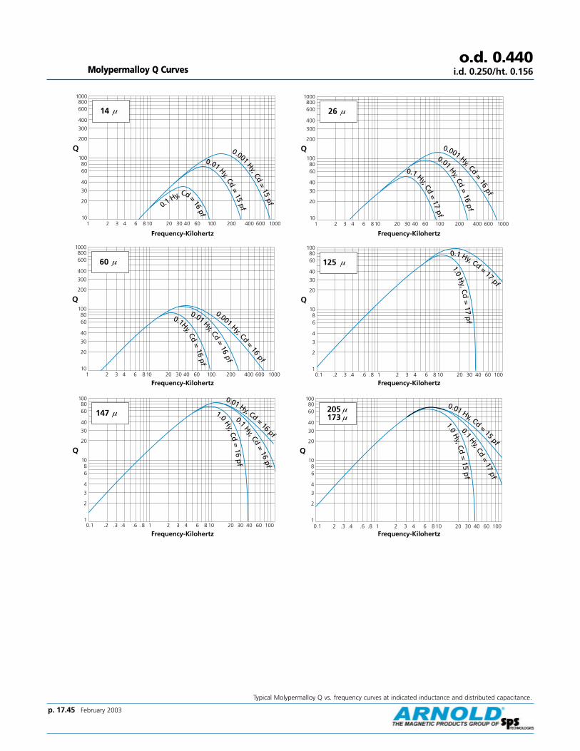
Typical Molypermalloy Q vs. frequency curves at indicated inductance and distributed capacitance.
Molypermalloy Q Curves
60 µ
10
20
30
40
6080
100
200
300
400
600800
1000
Q
1 2 3 4 6 8 10 20 30 40 60 100 200 400 600 1000fp
61=
dC,y
H1.0
fp61
=dC
,yH10.0
fp61
=dC
,y
H100.0
o.d. 0.440i.d. 0.250/ht. 0.156
Frequency-Kilohertz
Frequency-Kilohertz
Frequency-Kilohertz
Frequency-Kilohertz
Frequency-Kilohertz
Frequency-Kilohertz
14 µ
10
20
30
40
6080
100
200
300
400
600800
1000
Q
1 2 3 4 6 8 10 20 30 40 60 100 200 400 600 1000
fp61
=dC,yH1.0 fp51
=dC
,yH
100.0
fp51
=dC
,yH10.0
147 µ
1
2
3
4
68
10
20
30
40
6080
100
Q
0.1 .2 .3 .4 .6 .8 1 2 3 4 20 30 40 60 1006 8 10
fp61
=dC,yH10.0
fp61
=dC
,yH
1.0
fp
61=
dC,y
H0.1
26 µ
10
20
30
40
6080
100
200
300
400
600800
1000
Q
1 2 3 4 6 8 10 20 30 40 60 100 200 400 600 1000
fp71
=dC
,y
H1.0
fp61
=dC
,yH10.
0
fp61
=dC
,y
H100.0
125 µ
1
2
3
4
68
10
20
30
40
6080
100
Q
0.1 .2 .3 .4 .6 .8 1 2 3 4 20 30 40 60 1006 8 10
fp
71=
dC,y
H0.
1
fp71
=dC,yH1.0
1
2
3
4
68
10
20
30
40
6080
100
Q
205 µµ173 µµ
0.1 .2 .3 .4 .6 .8 1 2 3 4 20 30 40 60 1006 8 10
fp
51=
dC,y
H0.
1
fp71
=dC
,yH
1.0
fp51
=dC,y
H10.0
p. 17.45 February 2003
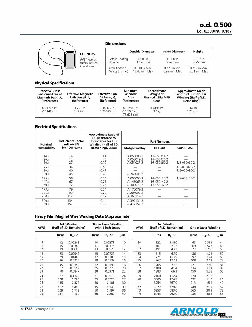
p. 17.46 February 2003
CORNERS:
0.031 Approx.Radius Bottom,Chamfer Top
o.d. 0.500i.d. 0.300/ht. 0.187
Effective CrossSectional Area ofMagnetic Path, Ae
(Reference)
Effective CoreVolume, Ve(Reference)
Minimum Window
Area (Reference)
Approximate Weight of
Finished 125µ MPPCore
Approximate MeanLength of Turn for FullWinding (Half of I.D.
Remaining)
0.01767 in2
0.1140 cm21.229 in3.124 cm
0.02172 in3
0.35568 cm30.05940 in2
0.38320 cm2
75,625 cmil
0.0066 lbs3.0 g
0.67 in1.71 cm
Nominal Permeability
Inductance Factor, mH +/- 8%
for 1000 turns
Approximate Ratio ofDC Resistance to
Inductance for FullWinding (Half of I.D.Remaining), Ω/mH
Part Numbers
Molypermalloy HI-FLUX SUPER-MSS
Dimensions
Outside Diameter Inside Diameter Height
Before Coating 0.500 in 0.300 in 0.187 inNominal 12.70 mm 7.62 mm 4.75 mm
After Coating 0.530 in Max. 0.275 in Min. 0.217 in Max.(White Enamel) 13.46 mm Max. 6.99 mm Min. 5.51 mm Max.
Effective MagneticPath Length, le
(Reference)
Physical Specifications
Electrical Specifications
Heavy Film Magnet Wire Winding Data (Approximate)
Full Winding Single Layer WindingAWG (Half of I.D. Remaining) with 1 inch Leads
Turns Rdc' Ω Turns Rdc' Ω lw' in.
15 12 0.00248 10 0.00271 1016 15 0.00389 11 0.00376 1117 19 0.00603 13 0.00520 12
18 23 0.00942 15 0.00722 1419 29 0.01462 17 0.0100 1520 36 0.0226 19 0.0139 16
21 45 0.0352 22 0.0193 1822 57 0.0552 25 0.0270 2023 70 0.0847 28 0.0371 22
24 87 0.1322 31 0.0518 2425 108 0.205 35 0.0723 2726 135 0.322 40 0.101 30
27 167 0.495 45 0.140 3328 209 0.779 50 0.197 3629 257 1.180 56 0.269 40
Full Winding AWG (Half of I.D. Remaining) Single Layer Winding
Turns Rdc' Ω Turns Rdc' Ω lw' in.
30 322 1.880 63 0.381 4431 401 2.93 69 0.527 4832 491 4.42 77 0.716 53
33 615 6.99 86 1.01 5934 771 11.09 97 1.44 6635 967 17.51 108 2.02 73
36 1205 27.3 121 2.80 8137 1488 41.4 134 3.81 8938 1883 66.1 150 5.38 100
39 2460 112.4 170 7.93 11340 3005 174.7 192 11.3 12641 3754 267.0 213 15.4 140
42 4822 429.0 240 21.7 15743 5953 683.0 265 30.9 17344 6943 962.0 285 40.1 186
14µ 6.4 3.1 A-053006-2 HF-050014-2 —26µ 12 1.6 A-052012-2 HF-050026-2 —60µ 27 0.70 A-051027-2 HF-050060-2 MS-050060-2
75µ 34 0.56 — — MS-050075-290µ 40 0.47 — — MS-050090-2
100µ 45 0.42 A-261045-2 — —
125µ 56 0.34 A-050056-2 HF-050125-2 MS-050125-2147µ 67 0.26 A-143067-2 HF-050147-2 —160µ 72 0.25 A-301072-2 HF-050160-2 —
173µ 79 0.24 A-172079-2 — —205µ 93 0.20 A-204093-2 — —250µ 112 0.17 A-368112-2 — —
300µ 134 0.14 A-390134-2 — —350µ 157 0.12 A-412157-2 — —

Typical Molypermalloy Q vs. frequency curves at indicated inductance and distributed capacitance.
Molypermalloy Q Curveso.d. 0.500
i.d. 0.300/ht. 0.187
0.1Hy,Cd=
20pf
0.01 Hy, Cd=
19pf
0.001H
y, Cd=
19pf
14 µ
10
20
30
40
6080
100
200
300
400
600800
1000
Q
1 2 3 4 6 8 10 20 30 40 60 100 200 400 600 1000
1.0Hy, Cd
=19
pf
0.1 Hy, Cd=
21pf
0.01 Hy, Cd=
16pf
0.001 Hy, Cd =
16pf
60 µ
10
20
30
40
6080
100
200
300
400
600800
1000
Q
1 2 3 4 6 8 10 20 30 40 60 100 200 400 600 1000
1.0H
y, Cd
=17
pf
0.1Hy, Cd
=17
pf
0.01 Hy, Cd = 16 pf
1
2
3
4
68
10
20
30
40
6080
100
Q
160 µµ147 µµ
0.1 .2 .3 .4 .6 .8 1 2 3 4 20 30 40 60 1006 8 10
0.1 Hy, Cd=
18pf
0.01Hy, Cd
=17
pf
0.001 Hy, Cd=
17pf
26 µ
10
20
30
40
6080
100
200
300
400
600800
1000
Q
1 2 3 4 6 8 10 20 30 40 60 100 200 400 600 1000
1.0 Hy, Cd=
19p
f
0.1 Hy, Cd=
18pf
0.01 Hy, Cd = 18 pf
125 µ
10
20
30
40
6080
100
200
300
400
600800
1000
Q
0.1 .2 .3 .4 .6 .8 1 2 3 4 20 30 40 60 1006 8 10
1.0H
y, Cd=
18p
f0.1
Hy, Cd=
18pf
0.01 Hy, Cd=
15pf
1
2
3
4
68
10
20
30
40
6080
100
Q
205 µµ173 µµ
0.1 .2 .3 .4 .6 .8 1 2 3 4 20 30 40 60 1006 8 10
p. 17.47 February 2003

p. 17.48 February 2003
o.d. 0.655i.d. 0.400/ht. 0.250
Effective CrossSectional Area ofMagnetic Path, Ae
(Reference)
Effective CoreVolume, Ve(Reference)
Minimum Window
Area (Reference)
Approximate Weight of
Finished 125µ MPPCore
Approximate MeanLength of Turn for FullWinding (Half of I.D.
Remaining)
0.0298 in2
0.1920 cm21.619 in4.11 cm
0.0483 in3
0.7891 cm30.11045 in2
0.71256 cm2
140,625 cmil
0.015 lbs6.8 g
0.86 in2.18 cm
Nominal Permeability
Inductance Factor, mH +/- 8%
for 1000 turns
Approximate Ratio ofDC Resistance to
Inductance for FullWinding (Half of I.D.Remaining), Ω/mH
Part Numbers
Molypermalloy HI-FLUX SUPER-MSS
Dimensions
Outside Diameter Inside Diameter Height
Before Coating 0.655 in 0.400 in 0.250 inNominal 16.64 mm 10.16 mm 6.35 mm
After Coating 0.685 in Max. 0.375 in Min. 0.280 in Max.(White Enamel) 17.40 mm Max. 9.53 mm Min. 7.11 mm Max.
Effective MagneticPath Length, le
(Reference)
Physical Specifications
Electrical Specifications
Heavy Film Magnet Wire Winding Data (Approximate)
Full Winding AWG (Half of I.D. Remaining) Single Layer Winding
Turns Rdc' Ω Turns Rdc' Ω lw' ft.
12 11 0.00150 10 0.00165 1.0413 14 0.00234 11 0.00230 1.1514 17 0.00365 13 0.00318 1.26
15 22 0.00569 15 0.00443 1.3916 27 0.00889 17 0.00617 1.5417 34 0.01375 19 0.00856 1.69
18 42 0.0215 21 0.0119 1.8719 53 0.0333 24 0.0166 2.0720 66 0.0516 27 0.0231 2.28
21 82 0.0802 31 0.0323 2.5322 103 0.1261 35 0.0453 2.8023 127 0.1937 39 0.0626 3.09
24 159 0.3026 44 0.0876 3.4125 197 0.471 49 0.123 3.7926 246 0.739 55 0.172 4.20
27 304 1.137 62 0.239 4.6428 380 1.792 69 0.336 5.1529 466 2.72 77 0.460 5.67
Full Winding AWG (Half of I.D. Remaining) Single Layer Winding
Turns Rdc' Ω Turns Rdc' Ω lw' ft.
30 586 4.34 86 0.654 6.3131 724 6.77 95 0.907 6.9332 892 10.22 105 1.23 7.61
33 1117 16.18 118 1.74 8.4534 1401 25.7 133 2.48 9.5035 1756 40.6 149 3.49 10.6
36 2190 63.3 165 4.85 11.737 2703 96.2 183 6.61 12.938 3422 153.6 205 9.33 14.4
39 4469 261.0 233 13.8 16.340 5459 406.0 262 19.7 18.341 6819 621.0 292 26.9 20.3
42 8759 998.0 329 37.8 22.843 10814 1590.0 363 53.9 25.1
14µ 8 1.6 A-268008-2 HF-065014-2 —26µ 15 0.86 A-267015-2 HF-065026-2 —60µ 36 0.36 A-266036-2 HF-065060-2 MS-065060-2
75µ 43 0.30 — — MS-065075-290µ 52 0.25 — — MS-065090-2
125µ 72 0.18 A-281072-2 HF-065125-2 MS-065125-2
147µ 88 0.15 A-264088-2 HF-065147-2 —160µ 92 0.14 A-285092-2 HF-065160-2 —173µ 104 0.12 A-263104-2 — —
205µ 123 0.11 A-262123-2 — —250µ 144 0.090 A-369144-2 — —300µ 173 0.074 A-391173-2 — —
CORNERS:
0.031 Approx.Radius (Typical)

Typical Molypermalloy Q vs. frequency curves at indicated inductance and distributed capacitance.
Molypermalloy Q Curveso.d. 0.655
i.d. 0.400/ht. 0.250
14 µ
10
20
30
40
6080
100
200
300
400
600800
1000
Q
1 2 3 4 6 8 10 20 30 40 60 100 200 400 600 1000
0.1 Hy, Cd=
27pf
0.01Hy, Cd
=26
pf
0.001 Hy, Cd=
21pf
Page 29
Frequency-Kilohertz
1 2 3 4 6 8 10 20 30 40 60 100 200 400 600 1000
60 µ
10
20
30
40
6080
100
200
300
400
600800
1000
Q
µ
1.0 Hy, Cd=
22pf
0.1Hy, Cd
=22
pf
0.01Hy, Cd
=22
pf
0.001Hy, Cd
=22
pf
Page 29
Frequency-Kilohertz
10
20
30
40
6080
100
200
300
400
600800
1000
Q
0.1 .2 .3 .4 .6 .8 1 2 3 4 20 30 40 60 1006 8 10
160 µµ147 µµ
1.0 Hy, Cd=
22pf
0.1 Hy, Cd=
22pf
0.01 Hy, Cd
=22
pf
Page 29
Frequency-Kilohertz
26 µ
10
20
30
40
6080
100
200
300
400
600800
1000
Q
1 2 3 4 6 8 10 20 30 40 60 100 200 400 600 1000
1.0 Hy, Cd=
23pf
0.1H
y, Cd=
22pf
0.01H
y, Cd=
23pf
0.001H
y, Cd=
23pf
Page 29
Frequency-Kilohertz
125 µ
10
20
30
40
6080
100
200
300
400
600800
1000
Q
µ
0.1 .2 .3 .4 .6 .8 1 2 3 4 20 30 40 60 1006 8 10
1.0H
y, Cd=
25p
f
0.1 Hy, Cd=
25pf
0.01 Hy, Cd = 20 pf
Page 29
Frequency-Kilohertz
10
20
30
40
6080
100
200
300
400
600800
1000
Q
0.1 .2 .3 .4 .6 .8 1 2 3 4 20 30 40 60 1006 8 10
205 µµ173 µµ
10 Hy, Cd=
20p
f
1.0 Hy, Cd=
23pf
0.1 Hy, Cd=
24pf
0.01 Hy, Cd
=21
pf
Page 29
Frequency-Kilohertz
p. 17.49 February 2003

p. 17.50 February 2003
o.d. 0.680i.d. 0.380/ht. 0.250
Effective CrossSectional Area ofMagnetic Path, Ae
(Reference)
Effective CoreVolume, Ve(Reference)
Minimum Window
Area (Reference)
Approximate Weight of
Finished 125µ MPPCore
Approximate MeanLength of Turn for FullWinding (Half of I.D.
Remaining)
0.0360 in2
0.232 cm21.63 in4.14 cm
0.05868 in3
0.9605 cm30.09898 in2
0.63858 cm2
126,025 cmil
0.0181 lbs8.2 g
0.90 in2.29 cm
Nominal Permeability
Inductance Factor, mH +/- 8%
for 1000 turns
Approximate Ratio ofDC Resistance to
Inductance for FullWinding (Half of I.D.Remaining), Ω/mH
Part Numbers
Molypermalloy HI-FLUX SUPER-MSS
14µ 10 1.5 A-187010-2 HF-068014-2 —26µ 19 0.80 A-188019-2 HF-068026-2 —60µ 43 0.35 A-189043-2 HF-068060-2 MS-068060-2
75µ 53 0.29 — — MS-068075-290µ 64 0.24 — — MS-068090-2
125µ 89 0.17 A-190089-2 HF-068125-2 MS-068125-2
147µ 105 0.15 A-193105-2 HF-068147-2 —160µ 114 0.13 A-559114-2 HF-068160-2 —173µ 123 0.12 A-194123-2 — —
205µ 146 0.10 A-205146-2 — —250µ 178 0.086 A-370178-2 — —300µ 214 0.071 A-392214-2 — —
Dimensions
Outside Diameter Inside Diameter Height
Before Coating 0.680 in 0.380 in 0.250 inNominal 17.27 mm 9.65 mm 6.35 mm
After Coating 0.710 in Max. 0.355 in Min. 0.280 in Max.(White Enamel) 18.03 mm Max. 9.02 mm Min. 7.11 mm Max.
Effective MagneticPath Length, le
(Reference)
Physical Specifications
Electrical Specifications
Heavy Film Magnet Wire Winding Data (Approximate)
Full Winding AWG (Half of I.D. Remaining) Single Layer Winding
Turns Rdc' Ω Turns Rdc' Ω lw' ft.
12 10 0.00140 9 0.00161 1.0113 13 0.00219 10 0.00225 1.1214 16 0.00342 12 0.00311 1.23
15 20 0.00533 14 0.00434 1.3616 25 0.00834 16 0.00606 1.5117 31 0.01292 18 0.00843 1.67
18 38 0.0202 20 0.0118 1.8419 48 0.0314 23 0.0164 2.0420 59 0.0486 26 0.0228 2.25
21 74 0.0756 29 0.0319 2.5022 92 0.1189 33 0.0449 2.7723 114 0.1828 37 0.0621 3.06
24 143 0.2860 41 0.0869 3.3925 177 0.4450 47 0.122 3.7626 221 0.6980 52 0.171 4.17
27 274 1.075 58 0.237 4.6128 342 1.695 65 0.334 5.1229 420 2.57 73 0.458 5.64
Full Winding AWG (Half of I.D. Remaining) Single Layer Winding
Turns Rdc' Ω Turns Rdc' Ω lw' ft.
30 527 4.10 82 0.651 6.2831 656 6.41 90 0.902 6.8932 802 9.68 100 1.23 7.57
33 1005 15.3 111 1.73 8.4134 1261 24.3 126 2.47 9.4635 1580 38.5 141 3.48 10.5
36 1970 60.0 156 4.84 11.737 2432 91.2 173 6.59 12.938 3077 146 194 9.31 14.4
39 4020 248 220 13.8 16.240 4910 385 248 19.7 18.241 6134 589 276 26.8 20.2
42 7878 947 311 37.7 22.843 9726 1508 343 53.7 25.144 11345 2130 369 69.8 26.9
CORNERS:
0.031 Approx.Radius (Typical)

Typical Molypermalloy Q vs. frequency curves at indicated inductance and distributed capacitance.
Molypermalloy Q Curveso.d. 0.680
i.d. 0.380/ht. 0.250
1 2 3 4 6 8 10 20 30 40 60 100 200 400 600 100010
20
30
40
6080
100
200
300
400
600800
1000
Q
14 µ
0.1 Hy, Cd=
30pf
0.01Hy, Cd
=23
pf
0.001Hy, Cd
=24
pf
Frequency-Kilohertz
1 2 3 4 6 8 10 20 30 40 60 100 200 400 600 100010
20
30
40
6080
100
200
300
400
600800
1000
Q
60 µ
1.0 Hy, Cd=
24p
f
0.1 Hy, Cd=
24pf
0.01 Hy, Cd=
25pf
0.001 Hy, Cd=
24pf
Frequency-Kilohertz
10
20
30
40
6080
100
200
300
400
600800
1000
Q
0.1 .2 .3 .4 .6 .8 1 2 3 4 20 30 40 60 1006 8 10
160 µµ147 µµ
10Hy, Cd=
28p
f
1.0H
y, Cd=
31pf
0.1 Hy, Cd=
24pf
0.01 Hy, Cd=
24pf
Frequency-Kilohertz
26 µ
10
20
30
40
6080
100
200
300
400
600800
1000
Q
1 2 3 4 6 8 10 20 30 40 60 100 200 400 600 1000
1.0 Hy, Cd=
26pf
0.1H
y, Cd=
25pf
0.01H
y, Cd=
25pf
0.001Hy, Cd
=25
pf
Frequency-Kilohertz
125 µ
10
20
30
40
6080
100
200
300
400
600800
1000
Q
µ
0.1 .2 .3 .4 .6 .8 1 2 3 4 20 30 40 60 1006 8 10
1.0 Hy, Cd=
25p
f
0.1Hy, Cd
=25
pf
0.01 Hy, Cd =20 pf
Frequency-Kilohertz
10
20
30
40
6080
100
200
300
400
600800
1000
Q
0.1 .2 .3 .4 .6 .8 1 2 3 4 20 30 40 60 1006 8 10
205 µµ173 µµ
10 Hy, Cd=
26p
f
1.0 Hy, Cd=
26pf
0.1 Hy, Cd=
26pf
0.01 Hy, Cd = 23 pf
Frequency-Kilohertz
p. 17.51 February 2003

p. 17.52 February 2003
o.d. 0.800i.d. 0.500/ht. 0.250
Effective CrossSectional Area ofMagnetic Path, Ae
(Reference)
Effective CoreVolume, Ve(Reference)
Minimum Window
Area (Reference)
Approximate Weight of
Finished 125µ MPPCore
Approximate MeanLength of Turn for FullWinding (Half of I.D.
Remaining)
0.035 in2
0.226 cm22.010 in5.093 cm
0.07035 in3
1.1510 cm30.1772 in2
1.1433 cm2
225,625 cmil
0.023 lbs10.0 g
0.90 in2.29 cm
Nominal Permeability
Inductance Factor, mH +/- 8%
for 1000 turns
Approximate Ratio ofDC Resistance to
Inductance for FullWinding (Half of I.D.Remaining), Ω/mH
Part Numbers
Molypermalloy HI-FLUX SUPER-MSS
14µ 7.8 1.1 A-057008-2 HF-080014-2 —26µ 14 0.60 A-511014-2 HF-080026-2 —60µ 32 0.26 A-848032-2 HF-080060-2 MS-080060-2
75µ 41 0.21 — — MS-080075-290µ 49 0.17 — — MS-080090-2
125µ 68 0.12 A-206068-2 HF-080125-2 MS-080125-2
147µ 81 0.10 A-144081-2 HF-080147-2 —150µ 83 0.10 A-241083-2 — —160µ 87 0.096 A-271087-2 HF-080160-2 —
173µ 96 0.088 A-173096-2 — —205µ 113 0.074 A-207113-2 — —250µ 136 0.062 A-371136-2 — —300µ 163 0.052 A-393163-2 — —
Dimensions
Outside Diameter Inside Diameter Height
Before Coating 0.800 in 0.500 in 0.250 inNominal 20.32 mm 12.70 mm 6.35 mm
After Coating 0.830 in Max. 0.475 in Min. 0.280 in Max.(Blue Epoxy) 21.08 mm Max. 12.07 mm Min. 7.11 mm Max.
Effective MagneticPath Length, le
(Reference)
Physical Specifications
Electrical Specifications
Heavy Film Magnet Wire Winding Data (Approximate)
Full Winding AWG (Half of I.D. Remaining) Single Layer Winding
Turns Rdc' Ω Turns Rdc' Ω lw' ft.
12 18 0.00254 13 0.00221 1.3913 22 0.00395 15 0.00307 1.5314 28 0.00614 17 0.00424 1.68
15 34 0.00954 19 0.00590 1.8516 43 0.01488 22 0.00822 2.0417 54 0.0230 25 0.0114 2.26
18 67 0.0358 28 0.0159 2.4919 84 0.0556 32 0.0222 2.7520 104 0.0860 35 0.0308 3.04
21 130 0.1337 40 0.0430 3.3622 163 0.210 45 0.0604 3.7323 201 0.323 50 0.0834 4.11
24 251 0.504 56 0.117 4.5525 312 0.784 63 0.164 5.0526 389 1.230 71 0.230 5.60
Full Winding AWG (Half of I.D. Remaining) Single Layer Winding
Turns Rdc' Ω Turns Rdc' Ω lw' ft.
27 481 1.894 79 0.318 6.1828 602 2.99 89 0.448 6.8729 738 4.53 98 0.614 7.56
30 927 7.23 110 0.872 8.4131 1154 11.29 122 1.21 9.2432 1412 17.04 134 1.64 10.2
33 1768 27.0 150 2.32 11.334 2218 42.8 169 3.31 12.735 2779 67.7 189 4.66 14.1
36 3466 105.5 210 6.48 15.637 4279 160.4 233 8.82 17.238 5415 256.0 261 12.5 19.2
39 7073 436.0 296 18.4 21.740 8641 678.0 333 26.4 24.441 10793 1036.0 370 35.9 27.1
CORNERS:
0.031 Approx.Radius (Typical)

Typical Molypermalloy Q vs. frequency curves at indicated inductance and distributed capacitance.
Molypermalloy Q Curveso.d. 0.800
i.d. 0.500/ht. 0.250
10
20
30
40
6080
100
200
300
400
600800
1000
Q
1 2 3 4 6 8 10 20 30 40 60 100 200 400 600 1000
14 µ
0.1 Hy, Cd=
27pf
0.01H
y, Cd=
27pf
0.001H
y, Cd=
23pf
Frequency-Kilohertz
10
20
30
40
6080
100
200
300
400
600800
1000
Q
60 µ
1 2 3 4 6 8 10 20 30 40 60 100 200 400 600 1000
1.0 Hy, Cd=
28p
f0.1
Hy, Cd
=22
pf0.01
Hy, Cd=
23pf
0.001Hy, Cd
=22
pf
Frequency-Kilohertz
10
20
30
40
6080
100
200
300
400
600800
1000
Q
0.1 .2 .3 .4 .6 .8 1 2 3 4 20 30 40 60 1006 8 10
160 µµ147 µµ
1.0H
y, Cd=
23p
f0.1
Hy, Cd=
23pf
0.01 Hy, Cd=
23pf
Frequency-Kilohertz
26 µ
10
20
30
40
6080
100
200
300
400
600800
1000
Q
1 2 3 4 6 8 10 20 30 40 60 100 200 400 600 1000
1.0 Hy, Cd=
23pf
0.1Hy, Cd
=23
pf0.01
Hy, Cd
=24
pf0.001
Hy, Cd
=24
pf
Frequency-Kilohertz
125 µ
10
20
30
40
6080
100
200
300
400
600800
1000
Q
µ
0.1 .2 .3 .4 .6 .8 1 2 3 4 20 30 40 60 1006 8 10
1.0H
y, Cd=
25p
f0.1
Hy, Cd
=25
pf
0.01 Hy, Cd=
21pf
Frequency-Kilohertz
10
20
30
40
6080
100
200
300
400
600800
1000
Q
0.1 .2 .3 .4 .6 .8 1 2 3 4 20 30 40 60 1006 8 10
205 µµ173 µµ
1.0Hy, Cd
=24
pf
0.1 Hy, Cd=
24pf
0.01 Hy, Cd
=22
pf
Frequency-Kilohertz
p. 17.53 February 2003

p. 17.54 February 2003
o.d. 0.900i.d. 0.550/ht.0.300
Effective CrossSectional Area ofMagnetic Path, Ae
(Reference)
Effective CoreVolume, Ve(Reference)
Minimum Window
Area (Reference)
Approximate Weight of
Finished 125µ MPPCore
Approximate MeanLength of Turn for FullWinding (Half of I.D.
Remaining)
0.0513 in2
0.331 cm22.233 in5.671 cm
0.11455 in3
1.8771 cm30.21813 in2
1.40727 cm2
277,729 cmil
0.033 lbs15 g
1.05 in2.67 cm
Nominal Permeability
Inductance Factor, mH +/- 8%
for 1000 turns
Approximate Ratio ofDC Resistance to
Inductance for FullWinding (Half of I.D.Remaining), Ω/mH
Part Numbers
Molypermalloy HI-FLUX SUPER-MSS
14µ 9.9 0.80 A-062010-2 HF-090014-2 —26µ 19 0.42 A-060019-2 HF-090026-2 MS-090026-260µ 43 0.19 A-059043-2 HF-090060-2 MS-090060-2
75µ 54 0.15 — — MS-090075-290µ 65 0.12 — — MS-090090-2
125µ 90 0.089 A-310090-2 HF-090125-2 MS-090125-2
147µ 106 0.075 A-147106-2 HF-090147-2 —160µ 115 0.070 A-300115-2 HF-090160-2 —173µ 124 0.064 A-174124-2 — —
205µ 147 0.054 A-208147-2 — —250µ 180 0.044 A-372180-2 — —300µ 216 0.037 A-394216-2 — —
Dimensions
Outside Diameter Inside Diameter Height
Before Coating 0.900 in 0.550 in 0.300 inNominal 22.86 mm 13.97 mm 7.62 mm
After Coating 0.930 in Max. 0.527 in Min. 0.330 in Max.(Blue Epoxy) 23.62 mm Max. 13.39 mm Min. 8.38 mm Max.
Effective MagneticPath Length, le
(Reference)
Physical Specifications
Electrical Specifications
Heavy Film Magnet Wire Winding Data (Approximate)
Full Winding AWG (Half of I.D. Remaining) Single Layer Winding
Turns Rdc' Ω Turns Rdc' Ω lw' ft.
12 21 0.00355 15 0.00276 1.7413 27 0.00552 17 0.00384 1.9214 34 0.00859 19 0.00532 2.11
15 42 0.01335 22 0.00742 2.3316 53 0.0208 25 0.0104 2.5817 66 0.0322 28 0.0144 2.85
18 82 0.0503 31 0.0202 3.1619 102 0.0782 35 0.0281 3.5020 127 0.1211 40 0.0392 3.87
21 158 0.1884 45 0.0548 4.2922 198 0.297 50 0.0771 4.7623 246 0.456 56 0.107 5.26
24 306 0.713 63 0.150 5.8325 381 1.110 71 0.210 6.4826 475 1.744 79 0.295 7.19
27 587 2.69 88 0.409 7.9528 734 4.24 99 0.577 8.8429 901 6.44 109 0.791 9.74
Full Winding AWG (Half of I.D. Remaining) Single Layer Winding
Turns Rdc' Ω Turns Rdc' Ω lw' ft.
30 1132 10.28 122 1.12 10.831 1408 16.07 135 1.56 11.932 1723 24.3 149 2.12 13.1
33 2158 38.4 166 3.00 14.634 2707 61.0 188 4.28 16.435 3391 96.5 210 6.03 18.2
36 4229 150.6 234 8.39 20.237 5221 229.0 259 11.4 22.338 6608 366.0 289 16.1 24.9
39 8630 623.0 328 23.9 28.240 10543 968.0 370 34.2 31.7
CORNERS:
0.031 Approx.Radius (Typical)

Typical Molypermalloy Q vs. frequency curves at indicated inductance and distributed capacitance.
Molypermalloy Q Curveso.d. 0.900
i.d. 0.550/ht.0.300
10
20
30
40
6080
100
200
300
400
600800
1000
Q
14 µ
1 2 3 4 6 8 10 20 30 40 60 100 200 400 600 1000
0.1H
y, Cd=
28pf
0.01H
y, Cd=
29pf
0.001H
y, Cd=
29pf
Frequency-Kilohertz
10
20
30
40
6080
100
200
300
400
600800
1000
Q
60 µ
1 2 3 4 6 8 10 20 30 40 60 100 200 400 600 1000
1.0 Hy, Cd=
28pf
0.1H
y, Cd=
29pf
0.01H
y, Cd=
29pf
0.001Hy, Cd
=24
pf
Frequency-Kilohertz
10
20
30
40
6080
100
200
300
400
600800
1000
Q
0.1 .2 .3 .4 .6 .8 1 2 3 4 20 30 40 60 1006 8 10
160 µµ147 µµ
10 Hy, Cd
=29
pf
1.0H
y, Cd=
29p
f
0.01 Hy, Cd=
25 pf
0.1 Hy, Cd=
30pf
Frequency-Kilohertz
26 µ
10
20
30
40
6080
100
200
300
400
600800
1000
Q
1 2 3 4 6 8 10 20 30 40 60 100 200 400 600 1000
1.0 Hy, Cd=
31pf
0.1H
y, Cd=
31pf
0.01H
y, Cd=
26pf
0.001Hy, Cd
=26
pf
Frequency-Kilohertz
125 µ
10
20
30
40
6080
100
200
300
400
600800
1000
Q
µ
0.1 .2 .3 .4 .6 .8 1 2 3 4 20 30 40 60 1006 8 10
1.0H
y, Cd=
27p
f
0.1Hy, Cd
=27
pf
0.01 Hy, Cd
=28
pf
Frequency-Kilohertz
10
20
30
40
6080
100
200
300
400
600800
1000
Q
0.1 .2 .3 .4 .6 .8 1 2 3 4 20 30 40 60 1006 8 10
205 µµ173 µµ
1.0Hy, Cd
=27
pf
0.1Hy, Cd
=26
pf
0.01 Hy, Cd
=26
pf
10 Hy, Cd=
28p
f
Frequency-Kilohertz
p. 17.55 February 2003
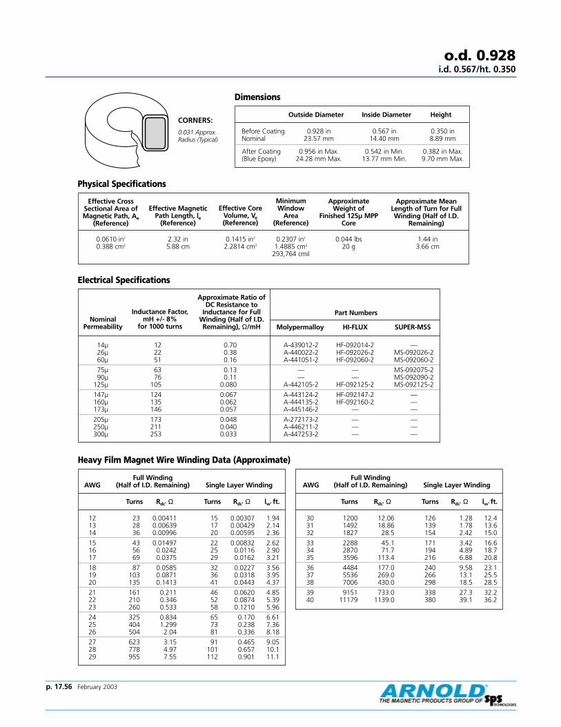
p. 17.56 February 2003
o.d. 0.928i.d. 0.567/ht. 0.350
Effective CrossSectional Area ofMagnetic Path, Ae
(Reference)
Effective CoreVolume, Ve(Reference)
Minimum Window
Area (Reference)
Approximate Weight of
Finished 125µ MPPCore
Approximate MeanLength of Turn for FullWinding (Half of I.D.
Remaining)
0.0610 in2
0.388 cm22.32 in5.88 cm
0.1415 in3
2.2814 cm30.2307 in2
1.4885 cm2
293,764 cmil
0.044 lbs20 g
1.44 in3.66 cm
Nominal Permeability
Inductance Factor, mH +/- 8%
for 1000 turns
Approximate Ratio ofDC Resistance to
Inductance for FullWinding (Half of I.D.Remaining), Ω/mH
Part Numbers
Molypermalloy HI-FLUX SUPER-MSS
14µ 12 0.70 A-439012-2 HF-092014-2 —26µ 22 0.38 A-440022-2 HF-092026-2 MS-092026-260µ 51 0.16 A-441051-2 HF-092060-2 MS-092060-2
75µ 63 0.13 — — MS-092075-290µ 76 0.11 — — MS-092090-2
125µ 105 0.080 A-442105-2 HF-092125-2 MS-092125-2
147µ 124 0.067 A-443124-2 HF-092147-2 —160µ 135 0.062 A-444135-2 HF-092160-2 —173µ 146 0.057 A-445146-2 — —
205µ 173 0.048 A-272173-2 — —250µ 211 0.040 A-446211-2 — —300µ 253 0.033 A-447253-2 — —
Effective MagneticPath Length, le
(Reference)
Physical Specifications
Electrical Specifications
Heavy Film Magnet Wire Winding Data (Approximate)
Full Winding AWG (Half of I.D. Remaining) Single Layer Winding
Turns Rdc' Ω Turns Rdc' Ω lw' ft.
12 23 0.00411 15 0.00307 1.9413 28 0.00639 17 0.00429 2.1414 36 0.00996 20 0.00595 2.36
15 43 0.01497 22 0.00832 2.6216 56 0.0242 25 0.0116 2.9017 69 0.0375 29 0.0162 3.21
18 87 0.0585 32 0.0227 3.5619 103 0.0871 36 0.0318 3.9520 135 0.1413 41 0.0443 4.37
21 161 0.211 46 0.0620 4.8522 210 0.346 52 0.0874 5.3923 260 0.533 58 0.1210 5.96
24 325 0.834 65 0.170 6.6125 404 1.299 73 0.238 7.3626 504 2.04 81 0.336 8.18
27 623 3.15 91 0.465 9.0528 778 4.97 101 0.657 10.129 955 7.55 112 0.901 11.1
Full Winding AWG (Half of I.D. Remaining) Single Layer Winding
Turns Rdc' Ω Turns Rdc' Ω lw' ft.
30 1200 12.06 126 1.28 12.431 1492 18.86 139 1.78 13.632 1827 28.5 154 2.42 15.0
33 2288 45.1 171 3.42 16.634 2870 71.7 194 4.89 18.735 3596 113.4 216 6.88 20.8
36 4484 177.0 240 9.58 23.137 5536 269.0 266 13.1 25.538 7006 430.0 298 18.5 28.5
39 9151 733.0 338 27.3 32.240 11179 1139.0 380 39.1 36.2
CORNERS:
0.031 Approx.Radius (Typical)
Dimensions
Outside Diameter Inside Diameter Height
Before Coating 0.928 in 0.567 in 0.350 inNominal 23.57 mm 14.40 mm 8.89 mm
After Coating 0.956 in Max. 0.542 in Min. 0.382 in Max.(Blue Epoxy) 24.28 mm Max. 13.77 mm Min. 9.70 mm Max.

Typical Molypermalloy Q vs. frequency curves at indicated inductance and distributed capacitance.
Molypermalloy Q Curves
0.1 .2 .3 .4 .6 .8 1 2 3 4 20 30 40 60 1006 8 1010
20
30
40
6080
100
200
300
400
600800
1000
Q
60 µ
1.0Hy, Cd
=29
pf
0.1H
y, Cd=
30pf
0.01 Hy, Cd=
31pf
0.001 Hy, Cd = 30 pf
Frequency-Kilohertz
Frequency-Kilohertz
Frequency-Kilohertz
Frequency-Kilohertz
Frequency-Kilohertz
Frequency-Kilohertz
o.d. 0.928i.d. 0.567/ht. 0.350
10
20
30
40
6080
100
200
300
400
600800
1000
Q
14 µ
1 2 3 4 6 8 10 20 30 40 60 100 200 400 600 1000
0.1 Hy, Cd=
36pf
1.0 Hy, Cd=
29pf
0.01H
y, Cd=
30pf
0.001H
y, Cd=
30pf
10
20
30
40
6080
100
200
300
400
600800
1000
Q
0.1 .2 .3 .4 .6 .8 1 2 3 4 20 30 40 60 1006 8 10
160 µµ147 µµ
10H
y, Cd=
30p
f1.0
Hy, Cd
=29
pf
0.01 Hy, Cd=
30pf
0.1Hy, Cd
=30
pf
26 µ
10
20
30
40
6080
100
200
300
400
600800
1000
Q
1 2 3 4 6 8 10 20 30 40 60 100 200 400 600 1000
1.0Hy, Cd
=30
pf
0.1H
y, Cd=
31pf
0.01H
y, Cd=
32pf
0.001H
y, Cd=
31pf
125 µ
10
20
30
40
6080
100
200
300
400
600800
1000
Q
µ
0.1 .2 .3 .4 .6 .8 1 2 3 4 20 30 40 60 1006 8 10
1.0H
y, Cd=
34p
f
10 Hy, Cd=
34p
f
0.1Hy, Cd
=34
pf
0.01 Hy, Cd = 28 pf
10
20
30
40
6080
100
200
300
400
600800
1000
Q
0.1 .2 .3 .4 .6 .8 1 2 3 4 20 30 40 60 1006 8 10
205 µµ173 µµ
1.0 Hy, Cd=
32pf
0.01 Hy, Cd=
29 pf
0.1Hy, Cd
=29
pf
10H
y, Cd=
32p
f
p. 17.57 February 2003

p. 17.58 February 2003
Full Winding AWG (Half of I.D. Remaining) Single Layer Winding
Turns Rdc' Ω Turns Rdc' Ω lw' ft.
12 24 0.00461 16 0.00325 2.0513 30 0.00719 18 0.00454 2.2714 37 0.0112 20 0.00630 2.50
15 47 0.0175 23 0.00881 2.7716 58 0.0274 26 0.0123 3.0717 73 0.0425 29 0.0172 3.40
18 91 0.0666 33 0.0241 3.7719 113 0.104 37 0.0337 4.1920 141 0.161 42 0.0470 4.64
21 176 0.252 47 0.0658 5.1522 220 0.396 53 0.0928 5.7323 273 0.611 59 0.129 6.33
24 340 0.958 66 0.180 7.0325 423 1.49 74 0.253 7.8326 528 2.35 83 0.357 8.70
27 652 3.63 93 0.495 9.63 28 815 5.73 104 0.699 10.729 1000 8.72 115 0.959 11.8
Effective CrossSectional Area ofMagnetic Path, Ae
(Reference)
Effective CoreVolume, Ve(Reference)
Minimum Window
Area (Reference)
Approximate Weight of
Finished 125µ MPPCore
Approximate MeanLength of Turn for FullWinding (Half of I.D.
Remaining)
0.07699 in2
0.49671 cm22.501 in6.352 cm
0.1925 in3
3.1551 cm30.2419 in2
1.5608 cm2
308,025 cmil
0.060 lbs27 g
1.25 in3.25 cm
Effective MagneticPath Length, le
(Reference)
Physical Specifications
Heavy Film Magnet Wire Winding Data (Approximate)
o.d. 1.060i.d. 0.580/ht. 0.340
Dimensions
Outside Diameter Inside Diameter Height
Before Coating 1.060 in 0.580 in 0.340 inNominal 26.92 mm 14.73 mm 8.64 mm
After Coating 1.090 in Max. 0.555 in Min. 0.3.72 in Max.(Blue Epoxy) 27.69 mm Max. 14.10 mm Min. 9.45 mm Max.
Full Winding AWG (Half of I.D. Remaining) Single Layer Winding
Turns Rdc' Ω Turns Rdc' Ω lw' ft.
30 1257 13.9 129 1.36 13.231 1563 21.8 142 1.89 14.532 1914 33.0 157 2.58 15.9
33 2396 52.3 175 3.64 17.734 3006 83.1 198 5.21 19.935 3767 132 221 7.33 22.2
36 4697 205 246 10.2 24.637 5798 313 272 13.9 27.238 7340 500 305 19.7 30.3
39 9590 851 346 29.1 34.340 11700 1320 389 41.6 38.6
CORNERS:
0.063 Approx.Radius (Typical)
Nominal Permeability
Inductance Factor, mH +/- 8%
for 1000 turns
Approximate Ratio ofDC Resistance to
Inductance for FullWinding (Half of I.D.Remaining), Ω/mH
Part Numbers
Molypermalloy HI-FLUX SUPER-MSS
14µ 13.8 0.64 A-676014-2 HF-107014-2 —26µ 25.5 0.34 A-677026-2 HF-107026-2 MS-107026-260µ 59.0 0.15 A-678059-2 HF-107060-2 MS-107060-2
75µ 73.7 0.12 — — MS-107075-290µ 88.4 0.10 — — MS-107090-2
125µ 123 0.072 A-679123-2 HF-107125-2 MS-107125-2
147µ 145 0.061 A-680145-2 HF-107147-2 —160µ 157 0.056 A-681157-2 HF-107160-2 —173µ 170 0.052 A-330170-2 — —
200µ 197 0.045 A-682197-2 — —250µ 246 0.036 A-683246-2 — —300µ 295 0.030 A-684295-2 —
Electrical Specifications
Typical Molypermalloy Q vs. frequency curves at indicated inductance and distributed capacitance.
Molypermalloy Q Curveso.d. 1.060
i.d. 0.580/ht. 0.340
Curves are currently not available. Please
contact our Powder Core Application Engineer
for
curve information at 1-800-545-4578.
p. 17.59 February 2003

p. 17.60 February 2003
o.d. 1.060i.d. 0.580/ht. 0.440
Effective CrossSectional Area ofMagnetic Path, Ae
(Reference)
Effective CoreVolume, Ve(Reference)
Minimum Window
Area (Reference)
Approximate Weight of
Finished 125µ MPPCore
Approximate MeanLength of Turn for FullWinding (Half of I.D.
Remaining)
0.1014 in2
0.654 cm22.501 in6.352 cm
.2536 in3
4.154 cm30.2419 in2
1.5608 cm2
308,025 cmil
0.080 lbs36 g
1.46 in3.71 cm
Nominal Permeability
Inductance Factor, mH +/- 8%
for 1000 turns
Approximate Ratio ofDC Resistance to
Inductance for FullWinding (Half of I.D.Remaining), Ω/mH
Part Numbers
Molypermalloy HI-FLUX SUPER-MSS
14µ 18 0.55 A-068018-2 HF-106014-2 —26µ 32 0.31 A-066032-2 HF-106026-2 MS-106026-260µ 75 0.133 A-894075-2 HF-106060-2 MS-106060-2
75µ 94 0.106 — — MS-106075-290µ 113 0.088 — — MS-106090-2
125µ 157 0.063 A-930157-2 HF-106125-2 MS-106125-2
147µ 185 0.054 A-145185-2 HF-106147-2 —160µ 201 0.050 A-302201-2 HF-106160-2 —173µ 217 0.046 A-175217-2 — —
205µ 257 0.039 A-209257-2 — —250µ 314 0.032 A-373314-2 — —300µ 377 0.026 A-396377-2 — —
Dimensions
Outside Diameter Inside Diameter Height
Before Coating 1.060 in 0.580 in 0.440 inNominal 26.92 mm 14.73 mm 11.18 mm
After Coating 1.090 in Max. 0.555 in Min. 0.472 in Max.(Blue Epoxy) 27.69 mm Max. 14.10 mm Min. 11.99 mm Max.
Effective MagneticPath Length, le
(Reference)
Physical Specifications
Electrical Specifications
Heavy Film Magnet Wire Winding Data (Approximate)
Full Winding AWG (Half of I.D. Remaining) Single Layer Winding
Turns Rdc' Ω Turns Rdc' Ω lw' ft.
12 24 0.00526 16 0.00367 2.3113 30 0.00820 18 0.00514 2.5714 37 0.01281 20 0.00715 2.83
15 47 0.01997 23 0.0100 3.1516 58 0.0313 26 0.0141 3.5017 73 0.0485 29 0.0197 3.89
18 91 0.0760 33 0.0276 4.3219 113 0.1183 37 0.0387 4.8120 141 0.1839 42 0.0541 5.34
21 176 0.287 47 0.0759 5.9422 220 0.452 53 0.107 6.6123 273 0.697 59 0.149 7.32
24 340 1.093 66 0.209 8.1325 423 1.704 74 0.294 9.0726 528 2.68 83 0.414 10.1
27 652 4.14 93 0.575 11.228 815 6.54 104 0.812 12.429 1000 9.95 115 1.11 13.7
Full Winding AWG (Half of I.D. Remaining) Single Layer Winding
Turns Rdc' Ω Turns Rdc' Ω lw' ft.
30 1257 15.90 129 1.59 15.331 1563 24.9 142 2.21 16.832 1914 37.6 157 3.00 18.5
33 2396 59.7 175 4.24 20.634 3006 94.8 198 6.07 23.235 3767 150.1 221 8.55 25.9
36 4697 234.0 246 11.9 28.737 5798 357.0 272 16.2 31.738 7339 570.0 305 22.9 35.4
39 9585 971.0 346 33.9 40.140 11709 1510.0 389 48.6 45.1
CORNERS:
0.063 Approx.Radius (Typical)
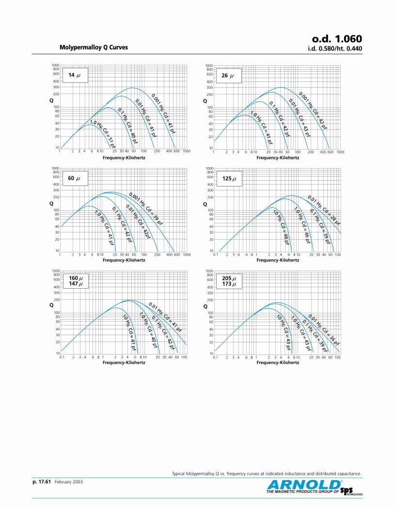
Typical Molypermalloy Q vs. frequency curves at indicated inductance and distributed capacitance.
Molypermalloy Q Curveso.d. 1.060
i.d. 0.580/ht. 0.440
10
20
30
40
6080
100
200
300
400
600800
1000
Q
14 µ
1 2 3 4 6 8 10 20 30 40 60 100 200 400 600 1000
0.1H
y, Cd=
40pf
1.0 Hy, Cd=
51pf
0.01H
y, Cd=
41pf
0.001H
y, Cd=
41pf
Frequency-Kilohertz
10
20
30
40
6080
100
200
300
400
600800
1000
Q
60 µ
1 2 3 4 6 8 10 20 30 40 60 100 200 400 600 1000
1.0 Hy, Cd=
41p
f0.1
Hy, Cd
=42
pf
0.01Hy, Cd
=42pf
0.001 Hy, Cd=
39pf
Frequency-Kilohertz
10
20
30
40
6080
100
200
300
400
600800
1000
Q
0.1 .2 .3 .4 .6 .8 1 2 3 4 20 30 40 60 1006 8 10
160 µµ147 µµ
10H
y, Cd=
41p
f1.0
Hy, Cd
=40
pf
0.01 Hy, Cd=
41pf
0.1Hy, Cd
=42
pf
Frequency-Kilohertz
26 µ
10
20
30
40
6080
100
200
300
400
600800
1000
Q
1 2 3 4 6 8 10 20 30 40 60 100 200 400 600 1000
1.0 Hy, Cd=
41pf
0.1H
y, Cd=
42pf
0.01H
y, Cd=
43pf
0.001Hy, Cd
=42
pf
Frequency-Kilohertz
125 µ
10
20
30
40
6080
100
200
300
400
600800
1000
Q
µ
0.1 .2 .3 .4 .6 .8 1 2 3 4 20 30 40 60 1006 8 10
1.0H
y, Cd=
46p
f
10 Hy, Cd
=48
pf
0.1H
y, Cd=
39pf
0.01 Hy, Cd
=28
pf
Frequency-Kilohertz
10
20
30
40
6080
100
200
300
400
600800
1000
Q
0.1 .2 .3 .4 .6 .8 1 2 3 4 20 30 40 60 1006 8 10
205 µµ173 µµ
1.0H
y, Cd=
43pf
0.01 Hy, Cd=
36pf
0.1Hy, Cd
=39
pf
10H
y, Cd=
43p
f
Frequency-Kilohertz
p. 17.61 February 2003

p. 17.62 February 2003
o.d. 1.300i.d. 0.785/ht. 0.345
Effective CrossSectional Area ofMagnetic Path, Ae
(Reference)
Effective CoreVolume, Ve(Reference)
Minimum Window
Area (Reference)
Approximate Weight of
Finished 125µ MPPCore
Approximate MeanLength of Turn for FullWinding (Half of I.D.
Remaining)
0.08543 in2
0.55116 cm23.207 in8.147 cm
0.2740 in3
4.4902 cm30.4537 in2
2.9267 cm2
577,600 cmil
0.086 lbs39 g
1.30 in3.30 cm
Nominal Permeability
Inductance Factor, mH +/- 8%
for 1000 turns
Approximate Ratio ofDC Resistance to
Inductance for FullWinding (Half of I.D.Remaining), Ω/mH
Part Numbers
Molypermalloy HI-FLUX SUPER-MSS
14µ 11.9 0.39 A-640012-2 HF-131014-2 —26µ 22.1 0.21 A-641022-2 HF-131026-2 MS-131026-260µ 51.0 0.090 A-642051-2 HF-131060-2 MS-131060-2
75µ 63.8 0.072 — — MS-131075-290µ 76.5 0.060 — — MS-131090-2
125µ 109 0.042 A-197109-2 HF-131125-2 MS-131125-2
147µ 129 0.036 A-162129-2 HF-131147-2 —160µ 136 0.034 A-643136-2 HF-131160-2 —173µ 151 0.031 A-166151-2 — —
205µ 180 0.026 A-210180-2 — —250µ 213 0.021 A-644213-2 — —
Dimensions
Outside Diameter Inside Diameter Height
Before Coating 1.300 in 0.785 in 0.345 inNominal 33.02 mm 19.94 mm 8.76 mm
After Coating 1.332 in Max. 0.760 in Min. 0.382 in Max.(Blue Epoxy) 33.83 mm Max. 19.30 mm Min. 9.70 mm Max.
Effective MagneticPath Length, le
(Reference)
Physical Specifications
Electrical Specifications
Heavy Film Magnet Wire Winding Data (Approximate)
Full Winding AWG (Half of I.D. Remaining) Single Layer Winding
Turns Rdc' Ω Turns Rdc' Ω lw' ft.
12 44 0.00892 23 0.00472 2.9713 55 0.01384 26 0.00658 3.2914 69 0.0215 29 0.00912 3.61
15 86 0.0335 32 0.0127 4.0116 108 0.0523 37 0.0178 4.4317 135 0.0809 41 0.0248 4.91
18 169 0.1264 46 0.0347 5.4419 210 0.197 52 0.0486 6.0320 262 0.305 58 0.0676 6.68
21 326 0.475 66 0.0947 7.4222 408 0.748 74 0.134 8.2423 505 1.152 82 0.185 9.11
24 630 1.803 92 0.260 10.125 783 2.81 103 0.364 11.326 978 4.42 115 0.513 12.5
Full Winding AWG (Half of I.D. Remaining) Single Layer Winding
Turns Rdc' Ω Turns Rdc' Ω lw' ft.
27 1209 6.82 128 0.712 13.828 1511 10.77 143 1.00 15.429 1854 16.36 159 1.38 17.0
30 2328 26.1 178 1.96 18.931 2897 40.9 196 2.72 20.832 3546 61.8 216 3.70 22.9
33 4440 97.9 241 5.23 25.434 5570 155.6 273 7.48 28.635 6979 246 304 10.5 31.8
36 8703 384 338 14.7 35.337 10744 585 374 20.0 39.0
CORNERS:
0.063 Approx.Radius (Typical)

Typical Molypermalloy Q vs. frequency curves at indicated inductance and distributed capacitance.
Molypermalloy Q Curveso.d. 1.300
i.d. 0.785/ht. 0.345
147 µ
10
20
30
40
6080
100
200
300
400
600800
1000
Q
µ
0.1 .2 .3 .4 .6 .8 1 2 3 4 20 30 40 60 1006 8 10
10H
y, Cd=
40p
f
1.0H
y, Cd=
34p
f0.1
Hy, Cd=
35pf
0.01 Hy, Cd=
35pf
Frequency-Kilohertz
205 µ
10
20
30
40
6080
100
200
300
400
600800
1000
Q
µ
0.1 .2 .3 .4 .6 .8 1 2 3 4 20 30 40 60 1006 8 10
10 Hy, Cd=
38pf
0.1 Hy, Cd=
34pf
0.01 Hy, Cd=
33pf
1.0Hy, Cd
=40
pf
Frequency-Kilohertz
125µ
10
20
30
40
6080
100
200
300
400
600800
1000
Q
µ
0.1 .2 .3 .4 .6 .8 1 2 3 4 20 30 40 60 1006 8 10
1.0H
y, Cd=
38p
f0.1
Hy, Cd
=33
pf
10H
y, Cd=
37p
f
0.01Hy, Cd=
33pf
Frequency-Kilohertz
173µ
10
20
30
40
6080
100
200
300
400
600800
1000
Q
µ
0.1 .2 .3 .4 .6 .8 1 2 3 4 20 30 40 60 1006 8 10
10H
y, Cd=
35p
f
0.1Hy, Cd
=38
pf
1.0Hy, Cd
=37
pf
0.01 Hy, Cd=
31pf
Page 41
Frequency-Kilohertz
p. 17.63 February 2003

p. 17.64 February 2003
o.d. 1.300i.d. 0.785/ht. 0.420
Effective CrossSectional Area ofMagnetic Path, Ae
(Reference)
Effective CoreVolume, Ve(Reference)
Minimum Window
Area (Reference)
Approximate Weight of
Finished 125µ MPPCore
Approximate MeanLength of Turn for FullWinding (Half of I.D.
Remaining)
0.1042 in2
0.672 cm23.207 in8.147 cm
0.3345 in3
5.4768 cm30.4537 in2
2.9267 cm2
577,600 cmil
0.106 lbs47 g
1.47 in3.72 cm
Nominal Permeability
Inductance Factor, mH +/- 8%
for 1000 turns
Approximate Ratio ofDC Resistance to
Inductance for FullWinding (Half of I.D.Remaining), Ω/mH
Part Numbers
Molypermalloy HI-FLUX SUPER-MSS
14µ 14 0.36 A-344014-2 HF-130014-2 —26µ 28 0.18 A-298028-2 HF-130026-2 MS-130026-260µ 61 0.083 A-291061-2 HF-130060-2 MS-130060-2
75µ 76 0.066 — — MS-130075-290µ 91 0.055 — — MS-130090-2
125µ 127 0.040 A-548127-2 HF-130125-2 MS-130125-2
147µ 150 0.034 A-148150-2 HF-130147-2 —160µ 163 0.031 A-303163-2 HF-130160-2 —173µ 176 0.029 A-176176-2 — —
205µ 208 0.024 A-211208-2 — —250µ 254 0.020 A-374254-2 — —
Dimensions
Outside Diameter Inside Diameter Height
Before Coating 1.300 in 0.785 in 0.420 inNominal 33.02 mm 19.94 mm 10.67 mm
After Coating 1.332 in Max. 0.760 in Min. 0.457 in Max.(Blue Epoxy) 33.83 mm Max. 19.30 mm Min. 11.61 mm Max.
Effective MagneticPath Length, le
(Reference)
Physical Specifications
Electrical Specifications
Heavy Film Magnet Wire Winding Data (Approximate)
Full Winding AWG (Half of I.D. Remaining) Single Layer Winding
Turns Rdc' Ω Turns Rdc' Ω lw' ft.
12 44 0.00989 23 0.00517 3.2513 55 0.01538 26 0.00722 3.6114 69 0.0240 29 0.0100 3.97
15 86 0.0373 32 0.0140 4.4116 108 0.0584 37 0.0197 4.8917 135 0.0904 41 0.0274 5.42
18 169 0.1414 46 0.0384 6.0219 210 0.220 52 0.0538 6.6920 262 0.342 58 0.0750 7.41
21 326 0.533 66 0.105 8.2422 408 0.840 74 0.148 9.1623 505 1.294 82 0.206 10.1
24 630 2.030 92 0.289 11.325 783 3.16 103 0.406 12.526 978 4.98 115 0.572 13.9
27 1209 7.68 128 0.794 15.428 1511 12.14 143 1.12 17.229 1854 18.45 159 1.54 18.9
Full Winding AWG (Half of I.D. Remaining) Single Layer Winding
Turns Rdc' Ω Turns Rdc' Ω lw' ft.
30 2328 29.5 178 2.19 21.131 2897 46.2 196 3.04 23.232 3546 69.8 216 4.14 25.6
33 4440 110.6 241 5.85 28.434 5570 175.9 273 8.37 32.035 6979 278 304 11.8 35.6
36 8703 434 338 16.4 39.637 10744 661 374 22.4 43.7
CORNERS
0.063 Approx.Radius (Typical)

Typical Molypermalloy Q vs. frequency curves at indicated inductance and distributed capacitance.
Molypermalloy Q Curves
10
20
30
40
6080
100
200
300
400
600800
1000
Q
1 2 3 4 6 8 10 20 30 40 200 400 600 100060 100
60 µµ
0.001Hy, Cd
=34
pf
0.01H
y, Cd=
36pf
0.1H
y, Cd=
43p
f
1.0H
y, Cd=
41p
f
Frequency-Kilohertz
Frequency-Kilohertz
Frequency-Kilohertz
Frequency-Kilohertz
Frequency-Kilohertz
Frequency-Kilohertz
o.d. 1.300i.d. 0.785/ht. 0.420
1 2 3 4 6 8 10 20 30 40 200 400 600 100060 10010
20
30
40
6080
100
200
300
400
600800
1000
Q
14µµ
0.001H
y, Cd=
41pf
0.01H
y, Cd=
41pf
0.1H
y, Cd=
40pf
1.0 Hy, Cd=
38pf
10
20
30
40
6080
100
200
300
400
600800
1000
Q
0.1 .2 .3 .4 .6 .8 1 2 3 4 20 30 40 60 1006 8 10
160 µ147µ
µµ
0.01 Hy, Cd=
35pf
0.1Hy, Cd
=43
pf
1.0H
y, Cd=
41p
f
10H
y, Cd=
40p
f
26 µ
10
20
30
40
6080
100
200
300
400
600800
1000
Q
µ
1 2 3 4 6 8 10 20 30 40 200 400 600 100060 100
0.001H
y, Cd=
37pf
0.01H
y, Cd=
38pf
0.1H
y, Cd=
45pf
1.0Hy, Cd
=43
pf
125 µ
10
20
30
40
6080
100
200
300
400
600800
1000
Q
µ
0.1 .2 .3 .4 .6 .8 1 2 3 4 20 30 40 60 1006 8 10
0.01 Hy, Cd=
39pf
0.1H
y, Cd=
40pf
1.0H
y, Cd=
38p
f
10H
y, Cd
=45
pf
205 µ173µ
10
20
30
40
6080
100
200
300
400
600800
1000
Q
µµ
0.1 .2 .3 .4 .6 .8 1 2 3 4 20 30 40 60 1006 8 10
0.1Hy, Cd
=37
pf
1.0H
y, Cd=
39pf
10H
y, Cd=
37pf
0.01 Hy, Cd=
37pf
p. 17.65 February 2003

p. 17.66 February 2003
o.d. 1.300i.d. 0.785/ht. 0.440
Effective CrossSectional Area ofMagnetic Path, Ae
(Reference)
Effective CoreVolume, Ve(Reference)
Minimum Window
Area (Reference)
Approximate Weight of
Finished 125µ MPPCore
Approximate MeanLength of Turn for FullWinding (Half of I.D.
Remaining)
0.1082 in2
0.6981 cm23.207 in8.147 cm
0.3470 in3
5.6870 cm30.4537 in2
2.9267 cm2
577,600 cmil
0.095 lbs43 g
1.50 in3.81 cm
Nominal Permeability
Inductance Factor, mH +/- 8%
for 1000 turns
Approximate Ratio ofDC Resistance to
Inductance for FullWinding (Half of I.D.Remaining), Ω/mH
Part Numbers
Molypermalloy HI-FLUX SUPER-MSS
14µ 15 0.35 A-074015-2 HF-132014-2 —26µ 28 0.19 A-073028-2 HF-132026-2 MS-132026-260µ 65 0.080 A-071065-2 HF-132060-2 MS-132060-2
75µ 80.8 0.064 — — MS-132075-290µ 96.9 0.054 — — MS-132090-2
125µ 135 0.039 A-645135-2 HF-132125-2 MS-132125-2
147µ 158 0.033 A-646158-2 HF-132147-2 —160µ 172 0.030 A-647172-2 HF-132160-2 —173µ 186 0.028 A-648186-2 — —
200µ 215 0.024 A-649215-2 — —250µ 269 0.019 A-650269-2 — —
Dimensions
Outside Diameter Inside Diameter Height
Before Coating 1.300 in 0.785 in 0.440 inNominal 33.02 mm 19.94 mm 11.18 mm
After Coating 1.332 in Max. 0.760 in Min. 0.472 in Max.(Blue Epoxy) 33.83 mm Max. 19.30 mm Min. 11.99 mm Max.
Effective MagneticPath Length, le
(Reference)
Physical Specifications
Electrical Specifications
Heavy Film Magnet Wire Winding Data (Approximate)
Full Winding AWG (Half of I.D. Remaining) Single Layer Winding
Turns Rdc' Ω Turns Rdc' Ω lw' ft.
12 44 0.0101 23 0.00526 3.3113 55 0.0157 26 0.00735 3.6714 69 0.0245 29 0.0102 4.04
15 86 0.0381 32 0.0143 4.4916 108 0.0596 37 0.0200 4.9817 135 0.0924 41 0.0279 5.53
18 169 0.1446 46 0.0392 6.1319 210 0.225 52 0.0548 6.8220 262 0.350 58 0.0765 7.55
21 326 0.545 66 0.107 8.4022 408 0.859 74 0.151 9.3523 505 1.324 82 0.210 10.3
24 630 2.08 92 0.295 11.525 783 3.24 103 0.414 12.826 978 5.09 115 0.584 14.2
27 1209 7.86 128 0.811 15.828 1511 12.43 143 1.15 17.529 1854 18.89 159 1.57 19.3
Full Winding AWG (Half of I.D. Remaining) Single Layer Winding
Turns Rdc' Ω Turns Rdc' Ω lw' ft.
30 2328 30.2 178 2.24 21.631 2897 47.3 196 3.11 23.732 3546 71.4 216 4.23 26.1
33 4440 113.2 241 5.97 29.034 5570 180.1 273 8.55 32.735 6979 285.0 304 12.0 36.4
36 8703 445.0 338 16.8 40.437 10744 677.0 374 22.9 44.6
CORNERS:
0.063 Approx.Radius (Typical)
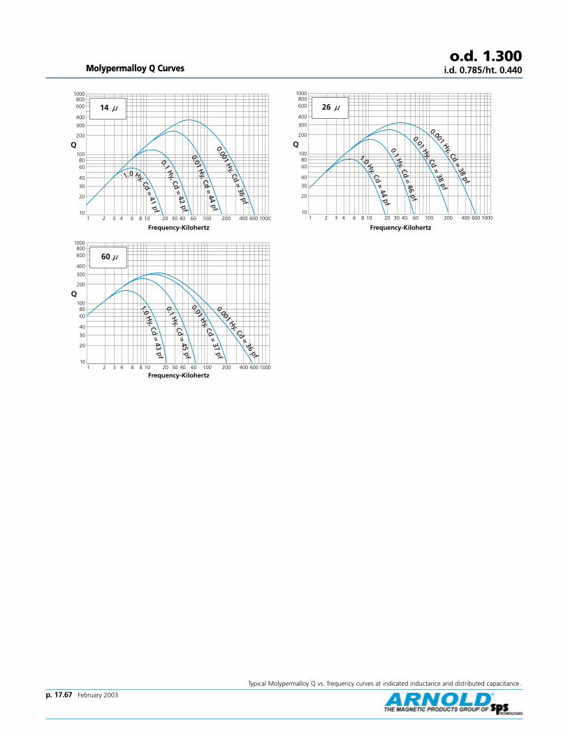
Typical Molypermalloy Q vs. frequency curves at indicated inductance and distributed capacitance.
Molypermalloy Q Curveso.d. 1.300
i.d. 0.785/ht. 0.440
14 µ
10
20
30
40
6080
100
200
300
400
600800
1000
Q
µ
1 2 3 4 6 8 10 20 30 40 200 400 600 100060 100
0.001H
y, Cd=
36pf
0.01H
y, Cd=
44pf
0.1H
y, Cd=
42pf
1.0 Hy, Cd=
41pf
Frequency-Kilohertz
60µ
10
20
30
40
6080
100
200
300
400
600800
1000
Q
µ
1 2 3 4 6 8 10 20 30 40 200 400 600 100060 100
1.0H
y, Cd=
43pf
0.01H
y, Cd=
37pf
0.001Hy, Cd
=36
pf
0.1H
y, Cd=
45pf
Frequency-Kilohertz
26 µ
10
20
30
40
6080
100
200
300
400
600800
1000
Q
µ
1 2 3 4 6 8 10 20 30 40 200 400 600 100060 100
0.001Hy, Cd
=38
pf
0.01H
y, Cd=
38pf
0.1H
y, Cd=
46pf
1.0Hy, Cd
=44
pf
Frequency-Kilohertz
p. 17.67 February 2003

p. 17.68 February 2003
o.d. 1.350i.d. 0.920/ht. 0.350
Effective CrossSectional Area ofMagnetic Path, Ae
(Reference)
Effective CoreVolume, Ve(Reference)
Minimum Window
Area (Reference)
Approximate Weight of
Finished 125µ MPPCore
Approximate MeanLength of Turn for FullWinding (Half of I.D.
Remaining)
0.0704 in2
0.454 cm23.523 in8.948 cm
0.2485 in3
4.0633 cm30.6193 in2
3.9956 cm2
788,544 cmil
0.081 lbs35 g
1.24 in3.16 cm
Nominal Permeability
Inductance Factor, mH +/- 8%
for 1000 turns
Approximate Ratio ofDC Resistance to
Inductance for FullWinding (Half of I.D.Remaining), Ω/mH
Part Numbers
Molypermalloy HI-FLUX SUPER-MSS
14µ 9 0.38 A-347009-2 HF-135014-2 —26µ 16 0.20 A-346016-2 HF-135026-2 MS-135026-260µ 38 0.082 A-345038-2 HF-135060-2 MS-135060-2
75µ 47 0.066 — — MS-135075-290µ 56 0.055 — — MS-135090-2
125µ 79 0.040 A-585079-2 HF-135125-2 MS-135125-2
147µ 93 0.034 A-149093-2 HF-135147-2 —160µ 101 0.031 A-304101-2 HF-135160-2 —173µ 109 0.029 A-177109-2 — —205µ 130 0.024 A-212130-2 — —
Dimensions
Outside Diameter Inside Diameter Height
Before Coating 1.350 in 0.920 in 0.350 inNominal 34.29 mm 23.37 mm 8.89 mm
After Coating 1.382 in Max. 0.888 in Min. 0.387 in Max.(Blue Epoxy) 35.10 mm Max. 22.56 mm Min. 9.83 mm Max.
Effective MagneticPath Length, le
(Reference)
Physical Specifications
Electrical Specifications
Heavy Film Magnet Wire Winding Data (Approximate)
Full Winding AWG (Half of I.D. Remaining) Single Layer Winding
Turns Rdc' Ω Turns Rdc' Ω lw' ft.
12 61 0.01185 27 0.00533 3.3513 76 0.01836 30 0.00740 3.7014 95 0.0285 34 0.0102 4.06
15 118 0.0443 38 0.0143 4.4916 148 0.0691 43 0.0199 4.9617 185 0.1068 49 0.0277 5.49
18 231 0.1667 55 0.0388 6.0719 288 0.259 61 0.0541 6.7320 358 0.402 69 0.0754 7.44
21 446 0.625 77 0.105 8.2622 559 0.984 87 0.148 9.1723 692 1.514 96 0.206 10.1
24 863 2.37 108 0.288 11.225 1073 3.69 121 0.404 12.526 1339 5.80 135 0.569 13.9
27 1655 8.95 150 0.789 15.328 2069 14.13 168 1.11 17.029 2539 21.5 186 1.53 18.8
Full Winding AWG (Half of I.D. Remaining) Single Layer Winding
Turns Rdc' Ω Turns Rdc' Ω lw' ft.
30 3188 34.3 208 2.17 20.931 3967 53.6 230 3.01 23.032 4856 81.0 253 4.10 25.3
33 6080 128.4 282 5.78 28.134 7627 204.0 319 8.27 31.735 9558 323.0 356 11.6 35.236 11918 503.0 396 16.2 39.1
CORNERS:
0.063 Approx.Radius (Typical)

Typical Molypermalloy Q vs. frequency curves at indicated inductance and distributed capacitance.
Molypermalloy Q Curveso.d. 1.350
i.d. 0.920/ht. 0.350
1 2 3 4 6 8 10 20 30 40 200 400 600 100060 10010
20
30
40
6080
100
200
300
400
600800
1000
Q
14µµ
0.001H
y, Cd=
30pf
0.01H
y, Cd=
29pf
0.1H
y, Cd=
35pf
Frequency-Kilohertz
10
20
30
40
6080
100
200
300
400
600800
1000
Q
1 2 3 4 6 8 10 20 30 40 200 400 600 100060 100
60 µµ
0.001Hy, Cd
=30
pf
0.01H
y, Cd=
31pf
0.1H
y, Cd=
30pf
1.0H
y, Cd=
35
Frequency-Kilohertz
10
20
30
40
6080
100
200
300
400
600800
1000
Q
0.1 .2 .3 .4 .6 .8 1 2 3 4 20 30 40 60 1006 8 10
160 µ147µ
µµ
0.01 Hy, Cd
=30
pf
0.1Hy, Cd
=30
pf
1.0H
y, Cd=
30p
f
Frequency-Kilohertz
26 µ
10
20
30
40
6080
100
200
300
400
600800
1000
Q
µ
1 2 3 4 6 8 10 20 30 40 200 400 600 100060 100
0.001H
y, Cd=
31pf
0.01H
y, Cd=
31pf
0.1H
y, Cd=
30pf
1.0Hy, Cd
=35
pf
Frequency-Kilohertz
125 µ
10
20
30
40
6080
100
200
300
400
600800
1000
Q
µ
0.1 .2 .3 .4 .6 .8 1 2 3 4 20 30 40 60 1006 8 10
0.01 Hy, Cd=
28pf
0.1H
y, Cd=
34pf
1.0H
y, Cd=
33p
f
Frequency-Kilohertz
205 µ173µ
10
20
30
40
6080
100
200
300
400
600800
1000
Q
µµ
0.1 .2 .3 .4 .6 .8 1 2 3 4 20 30 40 60 1006 8 10
0.1Hy, Cd
=25
pf
1.0Hy, Cd
=31
pf
10H
y, Cd=
32pf
0.01 Hy, Cd=
29pf
Frequency-Kilohertz
p. 17.69 February 2003

p. 17.70 February 2003
Effective CrossSectional Area ofMagnetic Path, Ae
(Reference)
Effective CoreVolume, Ve(Reference)
Minimum Window
Area (Reference)
Approximate Weight of
Finished 125µ MPPCore
Approximate MeanLength of Turn for FullWinding (Half of I.D.
Remaining)
0.1051 in2
0.678 cm23.54 in8.98 cm
0.3721 in3
6.0884 cm30.5648 in2
3.6438 cm2
719,104 cmil
0.112 lbs51 g
1.46 in3.72 cm
Nominal Permeability
Inductance Factor, mH +/- 8%
for 1000 turns
Approximate Ratio ofDC Resistance to
Inductance for FullWinding (Half of I.D.Remaining), Ω/mH Molypermalloy HI-FLUX SUPER-MSS
14µ 13 0.32 A-080013-2 HF-141014-2 —26µ 24 0.17 A-078024-2 HF-141026-2 MS-141026-260µ 56 0.074 A-076056-2 HF-141060-2 MS-141060-2
75µ 70.2 0.060 — — MS-141075-290µ 84.3 0.050 — — MS-141090-2
125µ 117 0.035 A-324117-2 HF-141125-2 MS-141125-2
147µ 138 0.030 A-150138-2 HF-141147-2 —160µ 150 0.028 A-305150-2 HF-141160-2 —173µ 162 0.026 A-178162-2 — —205µ 192 0.022 A-213192-2 — —
Dimensions
Outside Diameter Inside Diameter Height
Before Coating 1.410 in 0.880 in 0.412 inNominal 35.81 mm 22.35 mm 10.46 mm
After Coating 1.442 in Max. 0.848 in Min. 0.444 in Max.(Blue Epoxy) 36.63 mm Max. 21.54 mm Min. 11.28 mm Max.
Effective MagneticPath Length, le
(Reference)
Physical Specifications
Electrical Specifications
Heavy Film Magnet Wire Winding Data (Approximate)
Full Winding AWG (Half of I.D. Remaining) Single Layer Winding
Turns Rdc' Ω Turns Rdc' Ω lw' ft.
12 55 0.01241 25 0.00579 3.6513 69 0.01927 29 0.00809 4.0414 87 0.0300 32 0.0112 4.45
15 108 0.0467 37 0.0157 4.9316 135 0.0730 41 0.0220 5.4717 169 0.1131 46 0.0306 6.06
18 211 0.1768 52 0.0429 6.7219 263 0.275 58 0.0600 7.4620 327 0.427 65 0.0837 8.27
21 408 0.666 74 0.117 9.1922 511 1.050 82 0.166 10.223 632 1.617 92 0.229 11.3
24 788 2.53 103 0.322 12.525 980 3.95 115 0.452 14.026 1223 6.22 129 0.637 15.5
27 1512 9.59 143 0.885 17.228 1890 15.16 160 1.25 19.129 2319 23.0 177 1.71 21.1
Full Winding AWG (Half of I.D. Remaining) Single Layer Winding
Turns Rdc' Ω Turns Rdc' Ω lw' ft.
30 2913 36.8 199 2.44 23.531 3623 57.7 219 3.39 25.932 4435 87.1 242 4.61 28.5
33 5554 139.1 270 6.51 31.734 6967 220.0 305 9.32 35.735 8730 348.0 340 13.1 39.736 10886 543.0 378 18.3 44.0
o.d. 1.410i.d. 0.880/ht. 0.412
CORNERS:
0.063 Approx.Radius (Typical)
Part Numbers

Typical Molypermalloy Q vs. frequency curves at indicated inductance and distributed capacitance.
Molypermalloy Q Curves
60 µ
10
20
30
40
6080
100
200
300
400
600800
1000
Q
µ
0.1 .2 .3 .4 .6 .8 1 2 3 4 20 30 40 60 1006 8 101.0
Hy, Cd
=38
pf
0.1H
y, Cd=
40pf
0.01 Hy, Cd=
41pf
0.001 Hy, Cd = 33 pf
Page 47
Frequency-Kilohertz
Frequency-Kilohertz
Frequency-Kilohertz
Frequency-Kilohertz
Frequency-Kilohertz
Frequency-Kilohertz
o.d. 1.410i.d. 0.880/ht. 0.412
14 µ
10
20
30
40
6080
100
200
300
400
600800
1000
Q
1 2 3 4 6 8 10 20 30 40 60 100 200 400 600 1000
1.0 Hy, Cd=
45pf
0.1H
y, Cd=
38pf
0.01H
y, Cd=
39pf
0.001H
y, Cd=
39pf
Page 47
10
20
30
40
6080
100
200
300
400
600800
1000
Q
0.1 .2 .3 .4 .6 .8 1 2 3 4 20 30 40 60 1006 8 10
160 µµ147 µµ
10H
y, Cd=
38p
f1.0
Hy, Cd
=39
pf0.1
Hy, Cd
=41
pf
0.01 Hy, Cd=
35pf
Page 47
26 µ
10
20
30
40
6080
100
200
300
400
600800
1000
Q
1 2 3 4 6 8 10 20 30 40 60 100 200 400 600 1000
1.0H
y, Cd=
39pf
0.1H
y, Cd=
41pf
0.01H
y, Cd=
42pf
0.001H
y, Cd=
35pf
Page 47
10
20
30
40
6080
100
200
300
400
600800
1000
Q
0.1 .2 .3 .4 .6 .8 1 2 3 4 20 30 40 60 1006 8 10
125 µµ
10H
y, Cd=
43p
f
1.0H
y, Cd=
45p
f0.1
Hy, Cd
=38
pf
0.01 Hy, Cd
=38
pf
Page 47
10
20
30
40
6080
100
200
300
400
600800
1000
Q
0.1 .2 .3 .4 .6 .8 1 2 3 4 20 30 40 60 1006 8 10
205 µµ173 µµ
10H
y, Cd=
41p
f1.0
Hy, Cd
=37
pf0.1
Hy, Cd=
37pf
0.01
Hy, Cd=
36pf
Page 47
p. 17.71 February 2003

p. 17.72 February 2003
Effective CrossSectional Area ofMagnetic Path, Ae
(Reference)
Effective CoreVolume, Ve(Reference)
Minimum Window
Area (Reference)
Approximate Weight of
Finished 125µ MPPCore
Approximate MeanLength of Turn for FullWinding (Half of I.D.
Remaining)
0.1662 in2
1.072 cm23.877 in9.848 cm
0.6449 in3
10.5485 cm30.6619 in2
4.2702 cm2
842,724 cmil
0.206 lbs92 g
1.87 in4.76 cm
Nominal Permeability
Approximate Ratio ofDC Resistance to
Inductance for FullWinding (Half of I.D.Remaining), Ω/mH Molypermalloy HI-FLUX SUPER-MSS
14µ 19 0.24 A-086019-2 HF-157014-2 —26µ 35 0.13 A-085035-2 HF-157026-2 MS-157026-260µ 81 0.060 A-083081-2 HF-157060-2 MS-157060-2
75µ 101 0.045 — — MS-157075-290µ 121 0.038 — — MS-157090-2
125µ 168 0.027 A-254168-2 HF-157125-2 MS-157125-2
147µ 198 0.023 A-151198-2 HF-157147-2 —160µ 215 0.021 A-306215-2 HF-157160-2 —173µ 233 0.019 A-179233-2 — —205µ 276 0.016 A-214276-2 — —
Dimensions
Outside Diameter Inside Diameter Height
Before Coating 1.570 in 0.950 in 0.570 inNominal 39.88 mm 24.13 mm 14.48 mm
After Coating 1.602 in Max. 0.918 in Min. 0.605 in Max.(Blue Epoxy) 40.69 mm Max. 23.32 mm Min. 15.37 mm Max.
Effective MagneticPath Length, le
(Reference)
Physical Specifications
Electrical Specifications
Heavy Film Magnet Wire Winding Data (Approximate)
Full Winding AWG (Half of I.D. Remaining) Single Layer Winding
Turns Rdc' Ω Turns Rdc' Ω lw' ft.
10 — — 22 0.00389 3.8911 — — 25 0.00545 4.3212 65 0.01803 28 0.00762 4.80
13 81 0.0281 31 0.0107 5.3314 101 0.0438 35 0.0148 5.8815 126 0.0683 40 0.0208 6.55
16 158 0.1071 45 0.0292 7.2717 197 0.1662 50 0.0408 8.0818 247 0.260 57 0.0574 8.98
19 307 0.406 64 0.0804 9.9920 383 0.632 71 0.112 11.121 477 0.986 80 0.158 12.4
22 597 1.557 90 0.223 13.823 739 2.40 100 0.309 15.224 921 3.77 112 0.435 16.9
25 1145 5.88 125 0.611 18.926 1429 9.26 140 0.862 21.027 1767 14.31 155 1.20 23.3
Full Winding AWG (Half of I.D. Remaining) Single Layer Winding
Turns Rdc' Ω Turns Rdc' Ω lw' ft.
28 2209 22.6 174 1.69 25.929 2710 34.4 192 2.32 28.630 3404 55.1 215 3.31 31.9
31 4234 86.3 238 4.60 35.132 5183 130.4 262 6.26 38.733 6491 207.0 292 8.85 43.0
34 8142 329.0 330 12.7 48.535 10202 521.0 368 17.8 54.0
o.d. 1.570i.d. 0.950/ht. 0.570
CORNERS:
0.094 Approx.Radius (Typical)
Part NumbersInductance Factor, mH +/- 8%
for 1000 turns

Typical Molypermalloy Q vs. frequency curves at indicated inductance and distributed capacitance.
Molypermalloy Q Curveso.d. 1.570
i.d. 0.950/ht. 0.570
14 µ
10
20
30
40
6080
100
200
300
400
600800
1000
Q
1 2 3 4 6 8 10 20 30 40 60 100 200 400 600 1000
Page 49
1.0 Hy, Cd=
54pf
1.0H
y, Cd=
55pf
0.01H
y, Cd=
47pf
0.001H
y, Cd=
46pf
Frequency-Kilohertz
60 µ
10
20
30
40
6080
100
200
300
400
600800
1000
Q
0.1 .2 .3 .4 .6 .8 1 2 3 4 20 30 40 60 1006 8 10
Page 49
1.0H
y, Cd=
57pf
0.1H
y, Cd=
48pf
0.01 Hy, Cd=
48pf
0.001 Hy, Cd = 45 pf
Frequency-Kilohertz
10
20
30
40
6080
100
200
300
400
600800
1000
Q
160 µµ147 µµ
0.1 .2 .3 .4 .6 .8 1 2 3 4 20 30 40 60 1006 8 10
Page 49
10H
y, Cd=
55p
f1.0
Hy, Cd
=48
pf0.1
Hy, Cd=
48pf
0.01 Hy, Cd=
47pf
Frequency-Kilohertz
26 µ
10
20
30
40
6080
100
200
300
400
600800
1000
Q
1 2 3 4 6 8 10 20 30 40 60 100 200 400 600 1000
Page 49
1.0Hy, Cd
=58
pf
0.1H
y, Cd=
49pf
0.01H
y, Cd=
50pf
0.001Hy, Cd
=48
pf
Frequency-Kilohertz
125 µ
10
20
30
40
6080
100
200
300
400
600800
1000
Q
0.1 .2 .3 .4 .6 .8 1 2 3 4 20 30 40 60 1006 8 10
Page 49
10H
y, Cd
=50
pf
1.0H
y, Cd=
52p
f0.1
Hy, Cd
=54
pf
0.01 Hy, Cd=
44pf
Frequency-Kilohertz
10
20
30
40
6080
100
200
300
400
600800
1000
Q
205 µµ173 µµ
0.1 .2 .3 .4 .6 .8 1 2 3 4 20 30 40 60 1006 8 10
Page 49
10H
y, Cd=
51p
f1.0
Hy, Cd
=50
pf0.1
Hy, Cd=
51pf
0.01 Hy, Cd=
39pf
Frequency-Kilohertz
p. 17.73 February 2003

p. 17.74 February 2003
Effective CrossSectional Area ofMagnetic Path, Ae
(Reference)
Effective CoreVolume, Ve(Reference)
Minimum Window
Area (Reference)
Approximate Weight of
Finished 125µ MPPCore
Approximate MeanLength of Turn for FullWinding (Half of I.D.
Remaining)
0.308 in2
1.990 cm24.230 in
10.743 cm1.303 in3
21.373 cm30.6619 in2
4.2702 cm2
842,724 cmil
0.396 lbs180 g
2.42 in6.16 cm
Nominal Permeability
Approximate Ratio ofDC Resistance to
Inductance for FullWinding (Half of I.D.Remaining), Ω/mH Molypermalloy HI-FLUX SUPER-MSS
14µ 32 0.18 A-088032-2 HF-184014-2 —26µ 59 0.097 A-087059-2 HF-184026-2 MS-184026-260µ 135 0.043 A-759135-2 HF-184060-2 MS-184060-2
75µ 169 0.034 — — MS-184075-290µ 202 0.028 — — MS-184090-2
125µ 281 0.020 A-438281-2 HF-184125-2 MS-184125-2
147µ 330 0.017 A-152330-2 HF-184147-2 —160µ 360 0.016 A-325360-2 HF-184160-2 —173µ 390 0.015 A-180390-2 — —205µ 462 0.012 A-215462-2 — —
Dimensions
Outside Diameter Inside Diameter Height
Before Coating 1.840 in 0.950 in 0.710 inNominal 46.74 mm 24.13 mm 18.03 mm
After Coating 1.875 in Max. 0.918 in Min. 0.745 in Max.(Blue Epoxy) 47.63 mm Max. 23.32 mm Min. 18.92 mm Max.
Effective MagneticPath Length, le
(Reference)
Physical Specifications
Electrical Specifications
Heavy Film Magnet Wire Winding Data (Approximate)
Full Winding AWG (Half of I.D. Remaining) Single Layer Winding
Turns Rdc' Ω Turns Rdc' Ω lw' ft.
10 — — 22 0.00488 4.8911 — — 25 0.00688 5.4512 65 0.02275 28 0.00966 6.08
13 81 0.0355 31 0.0136 6.7814 101 0.0556 35 0.0189 7.5115 126 0.0868 40 0.0267 8.38
16 158 0.1363 45 0.0375 9.3417 197 0.212 50 0.0526 10.418 247 0.333 57 0.0740 11.6
19 307 0.520 64 0.104 12.920 383 0.810 71 0.146 14.421 477 1.265 80 0.205 16.0
22 597 2.00 90 0.290 17.923 739 3.09 100 0.403 19.824 921 4.85 112 0.567 22.1
25 1145 7.58 125 0.798 24.626 1429 11.96 140 1.13 27.527 1767 18.49 155 1.57 30.4
Full Winding AWG (Half of I.D. Remaining) Single Layer Winding
Turns Rdc' Ω Turns Rdc' Ω lw' ft.
28 2209 29.3 174 2.22 33.929 2710 44.6 192 3.04 37.530 3404 71.3 215 4.34 41.8
31 4234 111.7 238 6.03 46.132 5183 169.0 262 8.22 50.733 6491 268.0 292 11.6 56.5
34 8142 427.0 330 16.6 63.735 10202 676.0 368 23.5 70.9
o.d. 1.840i.d. 0.950/ht. 0.710
CORNERS:
0.094 Approx.Radius (Typical)
Part NumbersInductance Factor, mH +/- 8%
for 1000 turns
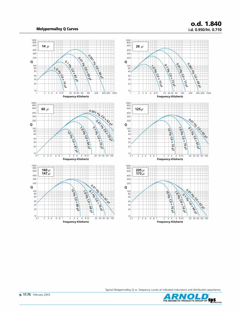
Typical Molypermalloy Q vs. frequency curves at indicated inductance and distributed capacitance.
Molypermalloy Q Curveso.d. 1.840
i.d. 0.950/ht. 0.710
10
20
30
40
6080
100
200
300
400
600800
1000
Q
1 2 3 4 6 8 10 20 30 40 60 100 200 400 600 1000
14 µ
1.0 Hy, Cd=
79pf
0.1 Hy, Cd=
83pf
0.01H
y, Cd=
69pf
0.001H
y, Cd=
66pf
Frequency-Kilohertz
60 µ
10
20
30
40
6080
100
200
300
400
600800
1000
Q
0.1 .2 .3 .4 .6 .8 1 2 3 4 20 30 40 60 1006 8 10
10H
y, Cd=
81pf
1.0H
y, Cd=
84p
f
0.1H
y, Cd=
70pf
0.01Hy, Cd
=70
pf
0.001 Hy, Cd = 63 pf
Frequency-Kilohertz
10
20
30
40
6080
100
200
300
400
600800
1000
Q
160 µµ147 µµ
0.1 .2 .3 .4 .6 .8 1 2 3 4 20 30 40 60 1006 8 10
10H
y, Cd=
80p
f
1.0H
y, Cd=
68p
f
0.01 Hy, Cd=
67pf
0.1Hy, Cd
=70
pf
Frequency-Kilohertz
10
20
30
40
6080
100
200
300
400
600800
1000
Q
1 2 3 4 6 8 10 20 30 40 60 100 200 400 600 1000
26 µ
1.0H
y, Cd=
70pf
0.1H
y, Cd=
73pf
0.01H
y, Cd=
73pf
0.001H
y, Cd=
69pf
Frequency-Kilohertz
125 µ
10
20
30
40
6080
100
200
300
400
600800
1000
Q
0.1 .2 .3 .4 .6 .8 1 2 3 4 20 30 40 60 1006 8 10
10H
y, Cd=
74p
f
1.0H
y, Cd=
78p
f0.1
Hy, Cd
=65
pf
0.01 Hy, Cd=
65pf
Frequency-Kilohertz
10
20
30
40
6080
100
200
300
400
600800
1000
Q
205 µµ173 µµ
0.1 .2 .3 .4 .6 .8 1 2 3 4 20 30 40 60 1006 8 10
10H
y, Cd=
70p
f
0.1Hy, Cd
=66
pf
1.0H
y, Cd=
74pf
0.01 Hy, Cd=
63pf
Frequency-Kilohertz
p. 17.75 February 2003
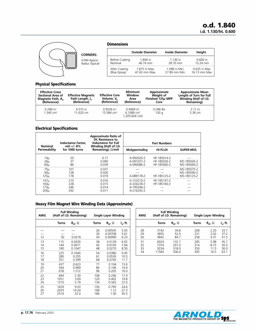
p. 17.76 February 2003
Effective CrossSectional Area ofMagnetic Path, Ae
(Reference)
Effective CoreVolume, Ve(Reference)
Minimum Window
Area (Reference)
Approximate Weight of
Finished 125µ MPPCore
Approximate MeanLength of Turn for FullWinding (Half of I.D.
Remaining)
0.208 in2
1.340 cm24.575 in
11.620 cm0.9526 in3
15.584 cm30.9469 in2
6.1089 cm2
1,205,604 cmil
0.286 lbs130 g
2.11 in5.36 cm
Nominal Permeability
Approximate Ratio ofDC Resistance to
Inductance for FullWinding (Half of I.D.Remaining), Ω/mH Molypermalloy HI-FLUX SUPER-MSS
14µ 20 0.17 A-092020-2 HF-185014-2 —26µ 37 0.090 A-091037-2 HF-185026-2 MS-185026-260µ 86 0.039 A-090086-2 HF-185060-2 MS-185060-2
75µ 107 0.031 — — MS-185075-290µ 128 0.026 — — MS-185090-2
125µ 178 0.019 A-089178-2 HF-185125-2 MS-185125-2
147µ 210 0.016 A-153210-2 HF-185147-2 —160µ 228 0.015 A-326228-2 HF-185160-2 —173µ 246 0.014 A-195246-2 — —205µ 292 0.011 A-216292-2 — —
Dimensions
Outside Diameter Inside Diameter Height
Before Coating 1.840 in 1.130 in 0.600 inNominal 46.74 mm 28.70 mm 15.24 mm
After Coating 1.875 in Max. 1.098 in Min. 0.635 in Max.(Blue Epoxy) 47.63 mm Max. 27.89 mm Min. 16.13 mm Max.
Effective MagneticPath Length, le
(Reference)
Physical Specifications
Electrical Specifications
Heavy Film Magnet Wire Winding Data (Approximate)
Full Winding AWG (Half of I.D. Remaining) Single Layer Winding
Turns Rdc' Ω Turns Rdc' Ω lw' ft.
— — — 26 0.00505 5.05— — — 30 0.00708 5.6112 92 0.0276 34 0.00990 6.23
13 115 0.0430 38 0.0139 6.9214 144 0.0671 43 0.0193 7.6415 180 0.1047 48 0.0270 8.50
16 225 0.1640 54 0.0380 9.4517 280 0.255 61 0.0530 10.518 351 0.399 68 0.0745 11.7
19 437 0.623 77 0.104 13.020 544 0.969 86 0.146 14.421 678 1.512 96 0.205 16.0
22 849 2.39 108 0.290 17.923 1051 3.69 120 0.402 19.824 1310 5.79 134 0.565 22.0
25 1629 9.03 150 0.795 24.626 2033 14.24 168 1.12 27.327 2514 22.0 186 1.56 30.3
Full Winding AWG (Half of I.D. Remaining) Single Layer Winding
Turns Rdc' Ω Turns Rdc' Ω lw' ft.
28 3142 34.8 208 2.20 33.729 3855 52.9 231 3.02 37.230 4842 84.7 258 4.31 41.5
31 6024 132.7 285 5.98 45.732 7374 201.0 314 8.15 50.333 9234 318.0 350 11.5 56.034 11583 506.0 395 16.5 63.1
o.d. 1.840i.d. 1.130/ht. 0.600
CORNERS:
0.094 Approx.Radius (Typical)
Part NumbersInductance Factor, mH +/- 8%
for 1000 turns
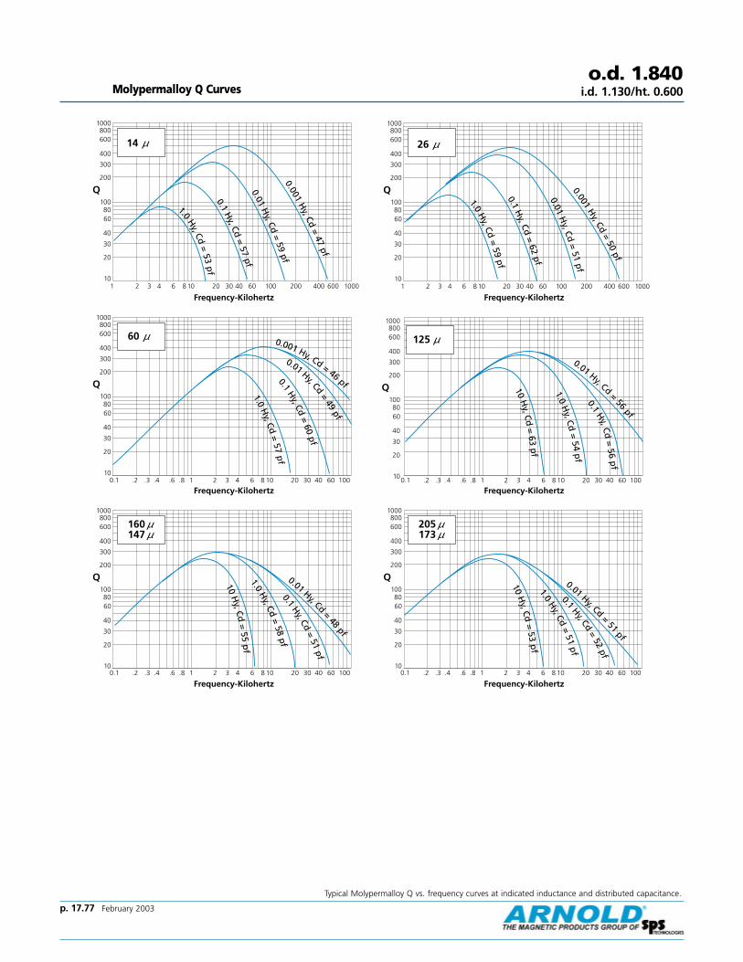
Typical Molypermalloy Q vs. frequency curves at indicated inductance and distributed capacitance.
Molypermalloy Q Curveso.d. 1.840
i.d. 1.130/ht. 0.600
10
20
30
40
6080
100
200
300
400
600800
1000
Q
1 2 3 4 6 8 10 20 30 40 60 100 200 400 600 1000
14 µ
1.0H
y, Cd=
53p
f0.1
Hy, Cd
=57
pf0.01
Hy, Cd
=59
pf0.001
Hy, Cd
=47
pf
Frequency-Kilohertz
60 µ
10
20
30
40
6080
100
200
300
400
600800
1000
Q
0.1 .2 .3 .4 .6 .8 1 2 3 4 20 30 40 60 1006 8 101.0
Hy, Cd
=57
pf0.1
Hy, Cd
=60
pf
0.01 Hy, Cd=
49pf
0.001 Hy, Cd = 46 pf
Frequency-Kilohertz
10
20
30
40
6080
100
200
300
400
600800
1000
Q
160 µµ147 µµ
0.1 .2 .3 .4 .6 .8 1 2 3 4 20 30 40 60 1006 8 10
10H
y, Cd=
55p
f1.0
Hy, Cd
=58
pf
0.01 Hy, Cd=
48pf
0.1Hy, Cd
=51
pf
Frequency-Kilohertz
10
20
30
40
6080
100
200
300
400
600800
1000
Q
1 2 3 4 6 8 10 20 30 40 60 100 200 400 600 1000
26 µ
1.0H
y, Cd=
59pf
0.1H
y, Cd=
62pf
0.01H
y, Cd=
51pf
0.001H
y, Cd=
50pf
Frequency-Kilohertz
125 µ
10
20
30
40
6080
100
200
300
400
600800
1000
Q
0.1 .2 .3 .4 .6 .8 1 2 3 4 20 30 40 60 1006 8 10
10H
y, Cd=
63p
f
1.0H
y, Cd=
54p
f0.1
Hy, Cd
=56
pf
0.01 Hy, Cd=
56pf
Frequency-Kilohertz
10
20
30
40
6080
100
200
300
400
600800
1000
Q
205 µµ173 µµ
0.1 .2 .3 .4 .6 .8 1 2 3 4 20 30 40 60 1006 8 10
10H
y, Cd=
53p
f
0.1Hy, Cd
=52
pf
1.0H
y, Cd=
51pf
0.01 Hy, Cd=
51pf
Frequency-Kilohertz
p. 17.77 February 2003

p. 17.78 February 2003
Effective CrossSectional Area ofMagnetic Path, Ae
(Reference)
Effective CoreVolume, Ve(Reference)
Minimum Window
Area (Reference)
Approximate Weight of
Finished 125µ MPPCore
Approximate MeanLength of Turn for FullWinding (Half of I.D.
Remaining)
0.194 in2
1.251 cm25.013 in
12.733 cm0.9739 in3
15.929 cm31.165 in2
7.517 cm2
1,483,524 cmil
0.313 lbs133 g
2.01 in5.11 cm
Nominal Permeability
Approximate Ratio ofDC Resistance to
Inductance for FullWinding (Half of I.D.Remaining), Ω/mH Molypermalloy HI-FLUX SUPER-MSS
14µ 17 0.15 A-349017-2 HF-200014-2 —26µ 32 0.080 A-348032-2 HF-200026-2 MS-200026-260µ 73 0.035 A-106073-2 HF-200060-2 MS-200060-2
75µ 91.2 0.028 — — MS-200075-290µ 109 0.023 — — MS-200090-2
125µ 152 0.017 A-715152-2 HF-200125-2 MS-200125-2
147µ 179 0.014 A-154179-2 HF-200147-2 —160µ 195 0.013 A-327195-2 HF-200160-2 —173µ 210 0.012 A-181210-2 — —205µ 249 0.010 A-217249-2 — —
Dimensions
Outside Diameter Inside Diameter Height
Before Coating 2.000 in 1.250 in 0.530 inNominal 50.80 mm 31.75 mm 13.46 mm
After Coating 2.035 in Max. 1.218 in Min. 0.565 in Max.(Blue Epoxy) 51.69 mm Max. 30.94 mm Min. 14.35 mm Max.
Effective MagneticPath Length, le
(Reference)
Physical Specifications
Electrical Specifications
Heavy Film Magnet Wire Winding Data (Approximate)
Full Winding AWG (Half of I.D. Remaining) Single Layer Winding
Turns Rdc' Ω Turns Rdc' Ω lw' ft.
10 — — 30 0.00539 5.4011 — — 33 0.00754 5.9812 113 0.0324 38 0.0105 6.64
13 141 0.0505 43 0.0147 7.3614 177 0.0788 48 0.0205 8.1115 221 0.1227 54 0.0287 9.02
16 276 0.1922 60 0.0402 10.017 344 0.298 68 0.0562 11.118 430 0.467 76 0.0788 12.3
19 537 0.728 85 0.110 13.720 668 1.133 95 0.154 15.221 832 1.768 107 0.216 16.9
22 1042 2.79 120 0.306 18.923 1289 4.31 133 0.424 20.924 1608 6.76 149 0.596 23.2
Full Winding AWG (Half of I.D. Remaining) Single Layer Winding
Turns Rdc' Ω Turns Rdc' Ω lw' ft.
25 1999 10.55 167 0.838 25.926 2495 16.62 186 1.18 28.827 3084 25.7 207 1.64 31.9
28 3855 40.6 231 2.32 35.529 4730 61.8 256 3.18 39.230 5941 98.8 287 4.53 43.7
31 7391 154.8 316 6.29 48.132 9048 234.0 349 8.57 52.933 11330 371.0 389 12.1 58.9
o.d. 2.000i.d. 1.250/ht. 0.530
CORNERS:
0.094Approx.Radius(Typical)
Part NumbersInductance Factor, mH +/- 8%
for 1000 turns

Typical Molypermalloy Q vs. frequency curves at indicated inductance and distributed capacitance.
Molypermalloy Q Curveso.d. 2.000
i.d. 1.250/ht. 0.530
10
20
30
40
6080
100
200
300
400
600800
1000
Q
1 2 3 4 6 8 10 20 30 40 60 100 200 400 600 1000
14 µ
1.0H
y, Cd=
57pf
0.1H
y, Cd=
49pf
0.01H
y, Cd=
51pf
0.001H
y, Cd=
50pf
Frequency-Kilohertz
60 µ
10
20
30
40
6080
100
200
300
400
600800
1000
Q
0.1 .2 .3 .4 .6 .8 1 2 3 4 20 30 40 60 1006 8 101.0
Hy, Cd
=50
pf0.1
Hy, Cd
=52
pf
0.01Hy, Cd=
52pf
0.001 Hy, Cd = 49 pf
Frequency-Kilohertz
10
20
30
40
6080
100
200
300
400
600800
1000
Q
160 µµ147 µµ
0.1 .2 .3 .4 .6 .8 1 2 3 4 20 30 40 60 1006 8 10
10H
y, Cd=
50p
f0.1
Hy, Cd
=50
pf0.01
Hy, Cd=
52pf
0.001 Hy, Cd=
51pf
Frequency-Kilohertz
10
20
30
40
6080
100
200
300
400
600800
1000
Q
26 µ
0.1 .2 .3 .4 .6 .8 1 2 3 4 20 30 40 60 1006 8 10
1.0H
y, Cd=
51pf
0.1H
y, Cd=
54pf
0.01 Hy, Cd=
55pf
0.001 Hy, Cd = 53 pf
Frequency-Kilohertz
125 µ
10
20
30
40
6080
100
200
300
400
600800
1000
Q
0.1 .2 .3 .4 .6 .8 1 2 3 4 20 30 40 60 1006 8 10
10H
y, Cd
=54
pf
1.0H
y, Cd=
57p
f0.1
Hy, Cd
=48
pf
0.01 Hy, Cd=
48pf
Frequency-Kilohertz
10
20
30
40
6080
100
200
300
400
600800
1000
Q
205 µµ173 µµ
0.1 .2 .3 .4 .6 .8 1 2 3 4 20 30 40 60 1006 8 10
10H
y, Cd=
52p
f
0.1Hy, Cd
=49
pf
0.01 Hy, Cd=
45pf
1.0H
y, Cd=
54pf
Frequency-Kilohertz
p. 17.79 February 2003
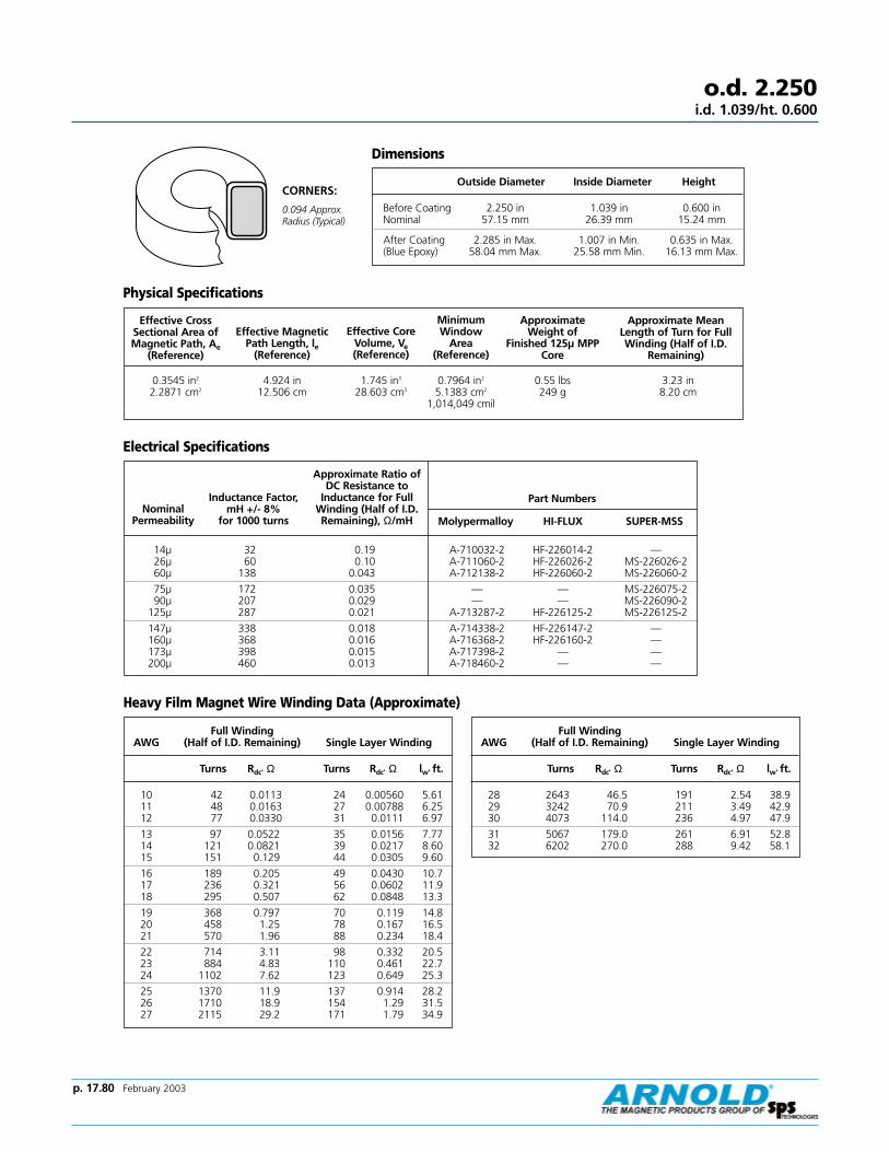
p. 17.80 February 2003
Effective CrossSectional Area ofMagnetic Path, Ae
(Reference)
Effective CoreVolume, Ve(Reference)
Minimum Window
Area (Reference)
Approximate Weight of
Finished 125µ MPPCore
Approximate MeanLength of Turn for FullWinding (Half of I.D.
Remaining)
0.3545 in2
2.2871 cm24.924 in
12.506 cm1.745 in3
28.603 cm30.7964 in2
5.1383 cm2
1,014,049 cmil
0.55 lbs249 g
3.23 in8.20 cm
Nominal Permeability
Approximate Ratio ofDC Resistance to
Inductance for FullWinding (Half of I.D.Remaining), Ω/mH Molypermalloy HI-FLUX SUPER-MSS
14µ 32 0.19 A-710032-2 HF-226014-2 —26µ 60 0.10 A-711060-2 HF-226026-2 MS-226026-260µ 138 0.043 A-712138-2 HF-226060-2 MS-226060-2
75µ 172 0.035 — — MS-226075-290µ 207 0.029 — — MS-226090-2
125µ 287 0.021 A-713287-2 HF-226125-2 MS-226125-2
147µ 338 0.018 A-714338-2 HF-226147-2 —160µ 368 0.016 A-716368-2 HF-226160-2 —173µ 398 0.015 A-717398-2 — —200µ 460 0.013 A-718460-2 — —
Dimensions
Outside Diameter Inside Diameter Height
Before Coating 2.250 in 1.039 in 0.600 inNominal 57.15 mm 26.39 mm 15.24 mm
After Coating 2.285 in Max. 1.007 in Min. 0.635 in Max.(Blue Epoxy) 58.04 mm Max. 25.58 mm Min. 16.13 mm Max.
Effective MagneticPath Length, le
(Reference)
Physical Specifications
Electrical Specifications
Heavy Film Magnet Wire Winding Data (Approximate)
Full Winding AWG (Half of I.D. Remaining) Single Layer Winding
Turns Rdc' Ω Turns Rdc' Ω lw' ft.
10 42 0.0113 24 0.00560 5.6111 48 0.0163 27 0.00788 6.2512 77 0.0330 31 0.0111 6.97
13 97 0.0522 35 0.0156 7.7714 121 0.0821 39 0.0217 8.6015 151 0.129 44 0.0305 9.60
16 189 0.205 49 0.0430 10.717 236 0.321 56 0.0602 11.918 295 0.507 62 0.0848 13.3
19 368 0.797 70 0.119 14.820 458 1.25 78 0.167 16.521 570 1.96 88 0.234 18.4
22 714 3.11 98 0.332 20.523 884 4.83 110 0.461 22.724 1102 7.62 123 0.649 25.3
25 1370 11.9 137 0.914 28.226 1710 18.9 154 1.29 31.527 2115 29.2 171 1.79 34.9
Full Winding AWG (Half of I.D. Remaining) Single Layer Winding
Turns Rdc' Ω Turns Rdc' Ω lw' ft.
28 2643 46.5 191 2.54 38.929 3242 70.9 211 3.49 42.930 4073 114.0 236 4.97 47.9
31 5067 179.0 261 6.91 52.832 6202 270.0 288 9.42 58.1
o.d. 2.250i.d. 1.039/ht. 0.600
CORNERS:
0.094 Approx.Radius (Typical)
Part NumbersInductance Factor, mH +/- 8%
for 1000 turns

p. 17.81 February 2003
Molypermalloy Q Curveso.d. 2.250
i.d. 1.039/ht. 0.600
Curves are currently not available. Please
contact our Powder Core Application Engineer
for
curve information at 1-800-545-4578.

p. 17.82 February 2003
Effective CrossSectional Area ofMagnetic Path, Ae
(Reference)
Effective CoreVolume, Ve(Reference)
Minimum Window
Area (Reference)
Approximate Weight of
Finished 125µ MPPCore
Approximate MeanLength of Turn for FullWinding (Half of I.D.
Remaining)
0.224 in2
1.444 cm25.628 in
14.296 cm1.261 in3
20.65 cm31.470 in2
9.483 cm2
1,871,424 cmil
0.385 lbs175 g
2.15 in5.47 cm
Nominal Permeability
Approximate Ratio ofDC Resistance to
Inductance for FullWinding (Half of I.D.Remaining), Ω/mH Molypermalloy HI-FLUX SUPER-MSS
14µ 18 0.12 A-096018-2 HF-225014-2 —26µ 33 0.066 A-094033-2 HF-225026-2 MS-225026-260µ 75 0.029 A-488075-2 HF-225060-2 MS-225060-2
75µ 93.6 0.023 — — MS-225075-290µ 112 0.019 — — MS-225090-2
125µ 156 0.014 A-109156-2 HF-225125-2 MS-225125-2
147µ 185 0.012 A-155185-2 HF-225147-2 —160µ 200 0.011 A-328200-2 HF-225160-2 —173µ 218 0.010 A-182218-2 — —205µ 259 0.0084 A-218259-2 — —
Dimensions
Outside Diameter Inside Diameter Height
Before Coating 2.250 in 1.400 in 0.550 inNominal 57.15 mm 35.56 mm 13.97 mm
After Coating 2.285 in Max. 1.368 in Min. 0.585 in Max.(Blue Epoxy) 58.04 mm Max. 34.75 mm Min. 14.86 mm Max.
Effective MagneticPath Length, le
(Reference)
Physical Specifications
Electrical Specifications
Heavy Film Magnet Wire Winding Data (Approximate)
Full Winding AWG (Half of I.D. Remaining) Single Layer Winding
Turns Rdc' Ω Turns Rdc' Ω lw' ft.
10 — — 34 0.00649 6.5011 — — 38 0.00908 7.2012 142 0.0435 43 0.0127 7.99
13 177 0.0677 48 0.0177 8.8714 222 0.1057 54 0.0247 9.7815 277 0.165 61 0.0346 10.9
16 347 0.258 68 0.0485 12.117 433 0.401 76 0.0678 13.418 541 0.628 86 0.0951 14.9
19 675 0.980 96 0.133 16.620 840 1.525 107 0.186 18.421 1046 2.38 120 0.261 20.5
22 1311 3.76 135 0.369 22.823 1622 5.80 150 0.512 25.224 2022 9.11 168 0.720 28.1
25 2514 14.22 188 1.01 31.326 3139 22.4 210 1.43 34.827 3880 34.6 233 1.98 38.6
Full Winding AWG (Half of I.D. Remaining) Single Layer Winding
Turns Rdc' Ω Turns Rdc' Ω lw' ft.
28 4850 54.8 260 2.80 42.929 5950 83.3 288 3.85 47.430 7473 133.3 322 5.48 52.9
31 9297 209.0 355 7.62 58.232 11380 316.0 392 10.4 64.1
o.d. 2.250i.d. 1.400/ht. 0.550
CORNERS:
0.094 Approx.Radius (Typical)
Part NumbersInductance Factor, mH +/- 8%
for 1000 turns

Typical Molypermalloy Q vs. frequency curves at indicated inductance and distributed capacitance.
Molypermalloy Q Curveso.d. 2.250
i.d. 1.400/ht. 0.550
10
20
30
40
6080
100
200
300
400
600800
1000
Q
1 2 3 4 6 8 10 20 30 40 60 100 200 400 600 1000
14 µ
1.0H
y, Cd=
52pf
0.1H
y, Cd=
55pf
0.01H
y, Cd=
56pf
0.001H
y, Cd=
56pf
Frequency-Kilohertz
60 µ
10
20
30
40
6080
100
200
300
400
600800
1000
Q
0.1 .2 .3 .4 .6 .8 1 2 3 4 20 30 40 60 1006 8 101.0
Hy, Cd
=55
pf0.1
Hy, Cd
=57
pf
0.01 Hy, Cd=
58pf
0.001 Hy, Cd = 54 pf
Frequency-Kilohertz
10
20
30
40
6080
100
200
300
400
600800
1000
Q
160 µµ147 µµ
0.1 .2 .3 .4 .6 .8 1 2 3 4 20 30 40 60 1006 8 10
10H
y, Cd=
53p
f
1.0H
y, Cd=
56pf
0.1Hy, Cd
=57
pf
0.01 Hy, Cd=
56pf
Frequency-Kilohertz
10
20
30
40
6080
100
200
300
400
600800
1000
Q
1 2 3 4 6 8 10 20 30 40 60 100 200 400 600 1000
26 µ
1.0H
y, Cd=
56pf
0.1H
y, Cd=
59pf
0.01H
y, Cd=
60pf
0.001H
y, Cd=
48pf
Frequency-Kilohertz
125 µ
10
20
30
40
6080
100
200
300
400
600800
1000
Q
0.1 .2 .3 .4 .6 .8 1 2 3 4 20 30 40 60 1006 8 10
10H
y, Cd=
60p
f
1.0H
y, Cd=
63pf
0.1Hy, Cd
=53
pf
0.01 Hy, Cd
=53
pf
Frequency-Kilohertz
10
20
30
40
6080
100
200
300
400
600800
1000
Q
205 µµ173 µµ
0.1 .2 .3 .4 .6 .8 1 2 3 4 20 30 40 60 1006 8 10
10H
y, Cd=
57p
f
0.1Hy, Cd
=54
pf
1.0H
y, Cd=
53pf
0.01 Hy, Cd=
50pf
Frequency-Kilohertz
p. 17.83 February 2003

p. 17.84 February 2003
Effective CrossSectional Area ofMagnetic Path, Ae
(Reference)
Effective CoreVolume, Ve(Reference)
Minimum Window
Area (Reference)
Approximate Weight of
Finished 125µ MPPCore
Approximate MeanLength of Turn for FullWinding (Half of I.D.
Remaining)
0.2748 in2
1.7729 cm27.721 in
19.612 cm2.122 in3
34.770 cm32.800 in2
18.062 cm2
3,564,544 cmil
0.64 lbs290 g
2.36 in5.99 cm
Nominal Permeability
Approximate Ratio ofDC Resistance to
Inductance for FullWinding (Half of I.D.Remaining), Ω/mH Molypermalloy HI-FLUX SUPER-MSS
14µ 16 0.076 A-335016-2 HF-300014-2 —26µ 30 0.041 A-124030-2 HF-300026-2 MS-300026-260µ 68 0.018 A-123068-2 HF-300060-2 MS-300060-2
75µ 85.2 0.014 — — MS-300075-290µ 102 0.012 — — MS-300090-2
125µ 142 0.0086 A-866142-2 HF-300125-2 MS-300125-2
147µ 167 0.0073 A-156167-2 HF-300147-2 —160µ 182 0.0067 A-685182-2 HF-300160-2 —173µ 197 0.0062 A-183197-2 — —205µ 233 0.0052 A-219233-2 — —
Dimensions
Outside Diameter Inside Diameter Height
Before Coating 3.063 in 1.938 in 0.500 inNominal 77.80 mm 49.23 mm 12.70 mm
After Coating 3.108 in Max. 1.888 in Min. 0.550 in Max.(Blue Epoxy) 78.94 mm Max. 47.96 mm Min. 13.97 mm Max.
Effective MagneticPath Length, le
(Reference)
Physical Specifications
Electrical Specifications
Heavy Film Magnet Wire Winding Data (Approximate)
Full Winding AWG (Half of I.D. Remaining) Single Layer Winding
Turns Rdc,' Ω Turns Rdc' Ω lw' ft.
10 — — 47 0.0100 10.011 — — 53 0.0140 11.112 271 0.0908 60 0.0196 12.3
13 339 0.1414 68 0.0274 13.714 424 0.221 75 0.0381 15.115 511 0.344 85 0.0534 16.8
16 664 0.540 95 0.0749 18.617 827 0.838 107 0.105 20.718 1034 1.314 119 0.147 23.0
19 1231 2.05 134 0.206 25.620 1605 3.19 149 0.288 28.421 1912 4.98 167 0.404 31.6
22 2504 7.88 187 0.570 35.223 3099 12.16 208 0.792 39.024 3863 19.09 232 1.11 43.3
25 4803 29.81 260 1.56 48.326 5996 47.0 290 2.21 53.827 7412 72.6 323 3.07 59.6
28 9265 114.9 360 4.33 66.429 11368 174.9 399 5.95 73.2
o.d. 3.063i.d. 1.938/ht. 0.500
CORNERS:
0.094 Approx.Radius (Typical)
Part NumbersInductance Factor, mH +/- 8%
for 1000 turns

Typical Molypermalloy Q vs. frequency curves at indicated inductance and distributed capacitance.
o.d. 3.063i.d. 1.938/ht. 0.500
10
20
30
40
6080
100
200
300
400
600800
1000
Q
1 2 3 4 6 8 10 20 30 40 60 100 200 400 600 1000
14µµ
1.0H
y, Cd=
66pf
0.1H
y, Cd=
57pf
0.01H
y, Cd=
59pf
0.001H
y, Cd=
58pf
Frequency-Kilohertz
10
20
30
40
6080
100
200
300
400
600800
1000
Q
0.1 .2 .3 .4 .6 .8 1 2 3 4 20 30 40 60 1006 8 10
125µµ
10H
y, Cd
=63
pf
1.0H
y, Cd=
66pf
0.1H
y, Cd=
68pf
Frequency-Kilohertz
10
20
30
40
6080
100
200
300
400
600800
1000
Q
0.1 .2 .3 .4 .6 .8 1 2 3 4 20 30 40 60 1006 8 10
173µµ
10H
y, Cd=
59p
f1.0
Hy, Cd
=63
pf0.1
Hy, Cd=
64pf
0.01 Hy, Cd=
62pf
Frequency-Kilohertz
10
20
30
40
6080
100
200
300
400
600800
1000
F Kil h
Q
0.1 .2 .3 .4 .6 .8 1 2 3 4 20 30 40 60 1006 8 10
26µµ
1.0H
y, Cd=
62pf
0.1H
y, Cd=
65pf
0.01Hy, Cd
=66
pf
Frequency-Kilohertz
10
20
30
40
6080
100
200
300
400
600800
1000
Q
60µµ
0.1 .2 .3 .4 .6 .8 1 2 3 4 20 30 40 60 1006 8 101.0
Hy, Cd
=57
pf0.1
Hy, Cd
=60
pf
0.01 Hy, Cd=
61pf
Frequency-Kilohertz
10
20
30
40
6080
100
200
300
400
600800
1000
Q
0.1 .2 .3 .4 .6 .8 1 2 3 4 20 30 40 60 1006 8 10
147µµ
10H
y, Cd
=68
pf
1.0H
y, Cd=
58p
f0.1
Hy, Cd=
60pf
0.01 Hy, Cd
=59
pf
Frequency-Kilohertz
10
20
30
40
6080
100
200
600800
1000
Q
0.1 .2 .3 .4 .6 .8 1 2 3 4 20 30 40 60 1006 8 10
205µµ
10H
y, Cd
=64
pf
1.0H
y, Cd=
68pf
0.1 Hy, Cd=
58pf
300
400
Frequency-Kilohertz
Molypermalloy Q Curves
p. 17.85 February 2003

p. 17.86 February 2003
o.d. 3.063i.d. 1.938/ht. 0.625
Effective CrossSectional Area ofMagnetic Path, Ae
(Reference)
Effective CoreVolume, Ve(Reference)
Minimum Window
Area (Reference)
Approximate Weight of
Finished 125µ MPPCore
Approximate MeanLength of Turn for FullWinding (Half of I.D.
Remaining)
0.3440 in2
2.2192 cm27.721 in
19.612 cm2.656 in3
43.523 cm32.800 in2
18.062 cm2
3,564,544 cmil
0.83 lbs377 g
3.90 in9.90 cm
Nominal Permeability
Approximate Ratio ofDC Resistance to
Inductance for FullWinding (Half of I.D.Remaining), Ω/mH Molypermalloy HI-FLUX SUPER-MSS
14µ 19.9 0.10 A-735020-2 HF-301014-2 MS-301014-226µ 37.0 0.056 A-736037-2 HF-301026-2 MS-301026-260µ 85.3 0.024 A-737085-2 HF-301060-2 MS-301060-2
75µ 107 0.019 — — MS-301075-290µ 128 0.016 — — MS-301090-2
125µ 178 0.012 A-740178-2 HF-301125-2 MS-301125-2
147µ 209 0.010 A-741209-2 HF-301147-2 —160µ 228 0.0090 A-742228-2 HF-301160-2 —173µ 246 0.0083 A-743246-2 — —205µ 284 0.0072 A-744284-2 — —
Dimensions
Outside Diameter Inside Diameter Height
Before Coating 3.063 in 1.938 in 0.625 inNominal 77.80 mm 49.23 mm 15.88 mm
After Coating 3.108 in Max. 1.888 in Min. 0.675 in Max.(Blue Epoxy) 78.94 mm Max. 47.96 mm Min. 17.15 mm Max.
Effective MagneticPath Length, le
(Reference)
Physical Specifications
Electrical Specifications
Heavy Film Magnet Wire Winding Data (Approximate)
Full Winding AWG (Half of I.D. Remaining) Single Layer Winding
Turns Rdc,' Ω Turns Rdc' Ω lw' ft.
10 — — 47 0.0110 11.011 — — 53 0.0154 12.212 275 0.142 60 0.0216 13.6
13 345 0.224 68 0.0302 15.114 424 0.347 75 0.0420 16.715 532 0.549 85 0.0590 18.5
16 664 0.867 95 0.0829 20.617 829 1.36 107 0.116 22.918 1036 2.15 119 0.163 25.5
19 1289 3.37 134 0.228 28.420 1608 5.27 149 0.318 31.521 2001 8.32 167 0.449 35.1
Heavy Film Magnet Wire Winding Data (Approximate)
Full Winding AWG (Half of I.D. Remaining) Single Layer Winding
Turns Rdc,' Ω Turns Rdc' Ω lw' ft.
22 2499 13.1 187 0.634 39.123 3081 20.3 208 0.880 43.324 3829 32.0 232 1.24 48.2
25 4793 50.4 260 1.74 53.826 5951 79.2 290 2.45 59.927 7322 122 323 3.41 66.3
28 9116 193 360 4.82 73.929 11126 293 399 6.62 81.5
CORNERS:
0.094 Approx.Radius (Typical)
Part NumbersInductance Factor, mH +/- 8%
for 1000 turns
p. 17.87 February 2003
Molypermalloy Q Curveso.d. 3.063
i.d. 1.938/ht. 0.625
Curves are currently not available. Please
contact our Powder Core Application Engineer
for
curve information at 1-800-545-4578.

p. 17.88 February 2003
Effective CrossSectional Area ofMagnetic Path, Ae
(Reference)
Effective CoreVolume, Ve(Reference)
Minimum Window
Area (Reference)
Approximate Weight of
Finished 125µ MPPCore
Approximate MeanLength of Turn for FullWinding (Half of I.D.
Remaining)
0.4606 in2
2.9716 cm29.555 in
24.271 cm4.401 in3
72.122 cm33.784 in2
24.413 cm2
4,818,025 cmils
1.21 lbs550 g
3.05 in7.76 cm
Nominal Permeability
Approximate Ratio ofDC Resistance to
Inductance for FullWinding (Half of I.D.Remaining), Ω/mH Molypermalloy HI-FLUX SUPER-MSS
14µ 21.5 0.055 A-651022-2 HF-401014-2 —26µ 40.0 0.029 A-126040-2 HF-401026-2 MS-401026-260µ 92.3 0.013 A-652092-2 HF-401060-2 MS-401060-2
75µ 115 0.010 — — MS-401075-290µ 139 0.0086 — — MS-401090-2
125µ 192 0.0062 A-653192-2 HF-401125-2 MS-401125-2
147µ 226 0.0053 A-654226-2 HF-401147-2 —160µ 246 0.0048 A-655246-2 HF-401160-2 —173µ 266 0.0045 A-656266-2 — —200µ 308 0.0039 A-657308-2 — —
Dimensions
Outside Diameter Inside Diameter Height
Before Coating 4.000 in 2.250 in 0.535 inNominal 101.60 mm 57.15 mm 13.59 mm
After Coating 4.050 in Max. 2.195 in Min. 0.585 in Max.(Blue Epoxy) 102.87 mm Max. 55.75 mm Min. 14.86 mm Max.
Effective MagneticPath Length, le
(Reference)
Physical Specifications
Electrical Specifications
Heavy Film Magnet Wire Winding Data (Approximate)
Full Winding AWG (Half of I.D. Remaining) Single Layer Winding
Turns Rdc' Ω Turns Rdc' Ω lw' ft.
10 — — 56 0.0147 14.811 — — 63 0.0207 16.412 366 0.1567 70 0.0289 18.2
13 457 0.244 79 0.0406 20.314 573 0.383 88 0.0565 22.415 716 0.598 99 0.0794 25.0
16 896 0.939 111 0.112 27.817 1116 1.461 124 0.156 30.918 1396 2.29 139 0.219 34.4
19 1740 3.59 156 0.308 38.320 2166 5.59 174 0.431 42.521 2698 8.74 195 0.605 47.4
22 3380 13.83 218 0.856 52.823 4183 21.4 242 1.19 58.624 5215 33.6 271 1.67 65.1
25 6483 52.5 303 2.35 72.726 8094 82.8 338 3.32 81.027 10004 128.1 376 4.62 89.7
o.d. 4.000i.d. 2.250/ht. 0.535
CORNERS:
0.125 Approx.Radius (Typical)
Part NumbersInductance Factor, mH +/- 8%
for 1000 turns

Typical Molypermalloy Q vs. frequency curves at indicated inductance and distributed capacitance.
Molypermalloy Q Curveso.d. 4.000
i.d. 2.250/ht. 0.535
10
20
30
40
6080
100
200
300
400
600800
1000
Q
26µµ
0.1 .2 .3 .4 .6 .8 1 2 3 4 20 30 40 60 1006 8 10
1.0H
y, Cd=
84pf
0.1H
y, Cd=
87pf
0.01H
y, Cd=
88pf
Frequency-Kilohertz
p. 17.89 February 2003
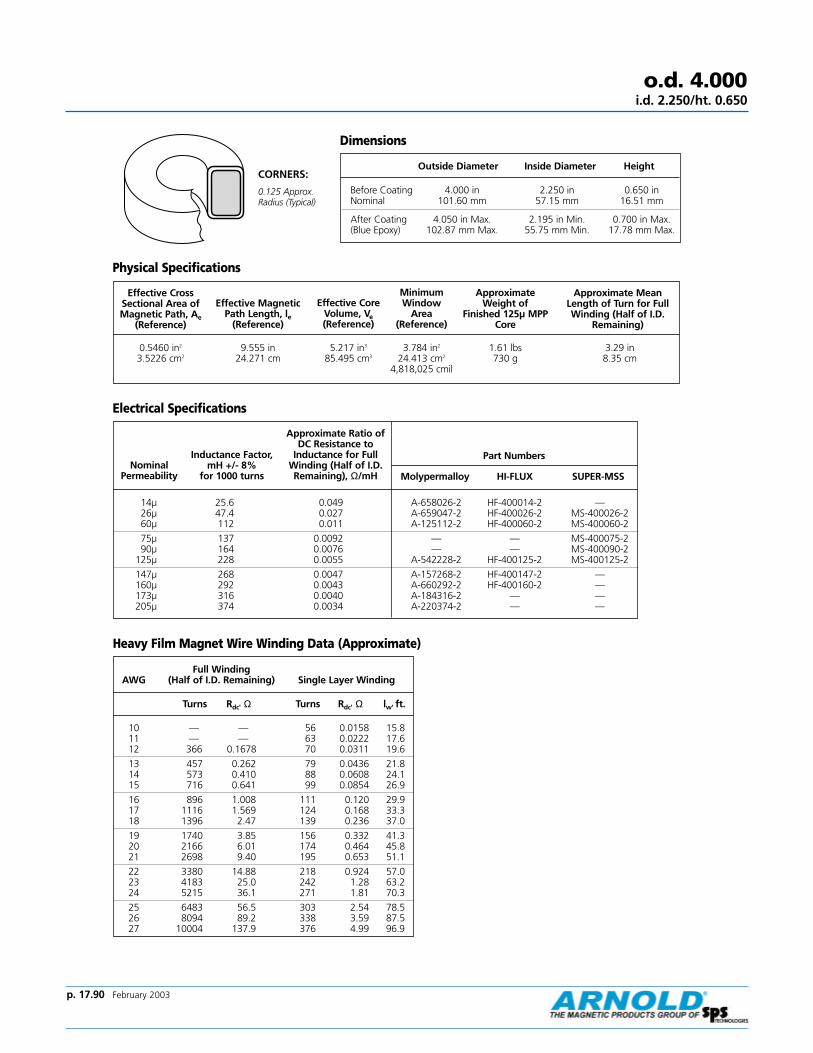
p. 17.90 February 2003
Effective CrossSectional Area ofMagnetic Path, Ae
(Reference)
Effective CoreVolume, Ve(Reference)
Minimum Window
Area (Reference)
Approximate Weight of
Finished 125µ MPPCore
Approximate MeanLength of Turn for FullWinding (Half of I.D.
Remaining)
0.5460 in2
3.5226 cm29.555 in
24.271 cm5.217 in3
85.495 cm33.784 in2
24.413 cm2
4,818,025 cmil
1.61 lbs730 g
3.29 in8.35 cm
Nominal Permeability
Approximate Ratio ofDC Resistance to
Inductance for FullWinding (Half of I.D.Remaining), Ω/mH Molypermalloy HI-FLUX SUPER-MSS
14µ 25.6 0.049 A-658026-2 HF-400014-2 —26µ 47.4 0.027 A-659047-2 HF-400026-2 MS-400026-260µ 112 0.011 A-125112-2 HF-400060-2 MS-400060-2
75µ 137 0.0092 — — MS-400075-290µ 164 0.0076 — — MS-400090-2
125µ 228 0.0055 A-542228-2 HF-400125-2 MS-400125-2
147µ 268 0.0047 A-157268-2 HF-400147-2 —160µ 292 0.0043 A-660292-2 HF-400160-2 —173µ 316 0.0040 A-184316-2 — —205µ 374 0.0034 A-220374-2 — —
Dimensions
Outside Diameter Inside Diameter Height
Before Coating 4.000 in 2.250 in 0.650 inNominal 101.60 mm 57.15 mm 16.51 mm
After Coating 4.050 in Max. 2.195 in Min. 0.700 in Max.(Blue Epoxy) 102.87 mm Max. 55.75 mm Min. 17.78 mm Max.
Effective MagneticPath Length, le
(Reference)
Physical Specifications
Electrical Specifications
Heavy Film Magnet Wire Winding Data (Approximate)
Full Winding AWG (Half of I.D. Remaining) Single Layer Winding
Turns Rdc' Ω Turns Rdc' Ω lw' ft.
10 — — 56 0.0158 15.811 — — 63 0.0222 17.612 366 0.1678 70 0.0311 19.6
13 457 0.262 79 0.0436 21.814 573 0.410 88 0.0608 24.115 716 0.641 99 0.0854 26.9
16 896 1.008 111 0.120 29.917 1116 1.569 124 0.168 33.318 1396 2.47 139 0.236 37.0
19 1740 3.85 156 0.332 41.320 2166 6.01 174 0.464 45.821 2698 9.40 195 0.653 51.1
22 3380 14.88 218 0.924 57.023 4183 25.0 242 1.28 63.224 5215 36.1 271 1.81 70.3
25 6483 56.5 303 2.54 78.526 8094 89.2 338 3.59 87.527 10004 137.9 376 4.99 96.9
o.d. 4.000i.d. 2.250/ht. 0.650
Part NumbersInductance Factor, mH +/- 8%
for 1000 turns
CORNERS:
0.125 Approx.Radius (Typical)

Typical Molypermalloy Q vs. frequency curves at indicated inductance and distributed capacitance.
Molypermalloy Q Curveso.d. 4.000
i.d. 2.250/ht. 0.650
10
20
30
40
6080
100
200
300
400
600800
1000
Q
125µµ
0.1 .2 .3 .4 .6 .8 1 2 3 4 20 30 40 60 1006 8 10
10H
y, Cd
=105
pf
1.0H
y, Cd=
89p
f0.1
Hy, Cd=
90pf
Frequency-Kilohertz
10
20
30
40
6080
100
200
300
400
600800
1000
Q
173µµ
0.01 .02 .03 .04 .06 .08 .1 .2 .3 .4 2 3 4 6 8 10.6 .8 1
10H
y, Cd=
99p
f
1.0 Hy, Cd=
103pf
0.1 Hy, Cd = 85 pf
Frequency-Kilohertz
10
20
30
40
6080
100
200
300
400
600800
1000
Q
60µµ
0.1 .2 .3 .4 .6 .8 1 2 3 4 20 30 40 60 1006 8 10
1.0H
y, Cd=
97p
f
10H
y, Cd=
92pf
0.1H
y, Cd=
99pf
0.01Hy, Cd
=98
pf
Frequency-Kilohertz
10
20
30
40
6080
100
200
300
400
600800
1000
Q
0.01 .02 .03 .04 .06 .08 .1 .2 .3 .4 2 3 4 6 8 10.6 .8 1
147µµ
10H
y, Cd=
92p
f
1.0 Hy, Cd=
95pf
0.1 Hy, Cd = 97 pf
Frequency-Kilohertz
10
20
30
40
6080
100
200
600800
1000
Q
0.01 .02 .03 .04 .06 .08 .1 .2 .3 .4 2 3 4 6 8 10.6 .8 1
205µµ
10H
y, Cd=
87p
f
1.0 Hy, Cd=
91pf
0.1 Hy, Cd = 92 pf
300
400
Frequency-Kilohertz
p. 17.91 February 2003

p. 17.92 February 2003
Effective CrossSectional Area ofMagnetic Path, Ae
(Reference)
Effective CoreVolume, Ve(Reference)
Minimum Window
Area (Reference)
Approximate Weight of
Finished 125µ MPPCore
Approximate MeanLength of Turn for FullWinding (Half of I.D.
Remaining)
0.8288 in2
5.3471 cm212.767 in33.12 cm
10.58 in3
173.40 cm37.225 in2
46.612 cm2
9,199,089 cmil
3.19 lbs1450 g
3.97 in10.09 cm
Nominal Permeability
Approximate Ratio ofDC Resistance to
Inductance for FullWinding (Half of I.D.Remaining), Ω/mH Molypermalloy HI-FLUX SUPER-MSS
14µ 26 0.031 A-430026-2 HF-520014-2 —26µ 54 0.015 A-129054-2 HF-520026-2 MS-520026-260µ 124 0.0064 A-128124-2 HF-520060-2 MS-520060-2
75µ 155 0.0052 — — MS-520075-290µ 187 0.0043 — — MS-520090-2
125µ 259 0.0031 A-127259-2 HF-520125-2 MS-520125-2
147µ 304 0.0026 A-158304-2 HF-520147-2 —160µ 332 0.0024 A-661332-2 HF-520160-2 —173µ 358 0.0022 A-185358-2 — —205µ 425 0.0019 A-221425-2 — —
Dimensions
Outside Diameter Inside Diameter Height
Before Coating 5.218 in 3.094 in 0.800 inNominal 132.54 mm 78.59 mm 20.32 mm
After Coating 5.274 in Max. 3.033 in Min. 0.855 in Max.(Blue Epoxy) 133.96 mm Max. 77.04 mm Min. 21.72 mm Max.
Effective MagneticPath Length, le
(Reference)
Physical Specifications
Electrical Specifications
Heavy Film Magnet Wire Winding Data (Approximate)
Full Winding AWG (Half of I.D. Remaining) Single Layer Winding
Turns Rdc' Ω Turns Rdc' Ω lw' ft.
10 — — 78 0.0266 26.611 — — 88 0.0374 29.612 695 0.382 98 0.0524 33.0
13 869 0.598 110 0.0735 36.714 1088 0.937 123 0.103 40.615 1360 1.467 138 0.144 45.3
16 1702 2.31 155 0.203 50.517 2121 3.60 173 0.284 56.218 2652 5.65 193 0.400 62.6
19 3307 8.84 216 0.562 69.820 4116 13.80 241 0.786 77.621 5127 21.6 270 1.11 86.5
22 6421 34.2 302 1.56 96.523 7947 52.9 336 2.17 10724 9908 83.2 375 3.06 11925 12318 130.1 420 4.31 133
o.d. 5.218i.d. 3.094/ht. 0.800
CORNERS:
0.125 Approx.Radius (Typical)
Part NumbersInductance Factor, mH +/- 8%
for 1000 turns

Typical Molypermalloy Q vs. frequency curves at indicated inductance and distributed capacitance.
10
20
30
40
6080
100
200
600800
1000
Q
0.01 .02 .03 .04 .06 .08 .1 .2 .3 .4 2 3 4 6 8 10.6 .8 1
300
400205 µµ
10H
y, Cd=
107p
f
1.0 Hy, Cd = 111 pf
Frequency-Kilohertz
Molypermalloy Q Curveso.d. 5.218
i.d. 3.094/ht. 0.800
10
20
30
40
6080
100
200
300
400
600800
1000
Q
0.1 .2 .3 .4 .6 .8 1 2 3 4 20 30 40 60 1006 8 10
14 µµ
0.1H
y, Cd=
109pf
1.0H
y, Cd=
105pf
0.01H
y, Cd=
110pf
Frequency-Kilohertz
10
20
30
40
6080
100
200
300
400
600800
1000
Q
0.1 .2 .3 .4 .6 .8 1 2 3 4 20 30 40 60 1006 8 10
60 µµ
1.0H
y, Cd=
117p
f
10H
y, Cd=
121p
f
0.1H
y, Cd=
120pf
Frequency-Kilohertz
10
20
30
40
6080
100
200
300
400
600800
1000
Q
0.01 .02 .03 .04 .06 .08 .1 .2 .3 .4 2 3 4 6 8 10.6 .8 1
147µµ
10H
y, Cd=
114p
f
1.0 Hy, Cd=
118pf
0.1 Hy, Cd = 118 pf
Frequency-Kilohertz
10
20
30
40
6080
100
200
300
400
600800
1000
Q
0.1 .2 .3 .4 .6 .8 1 2 3 4 20 30 40 60 1006 8 10
26 µµ
1.0H
y, Cd=
120pf
0.1H
y, Cd=
124pf
0.01H
y, Cd=
150pf
Frequency-Kilohertz
0.01 .02 .03 .04 .06 .08 .1 .2 .3 .4 2 3 4 6 8 10.6 .8 110
20
30
40
6080
100
200
300
400
600800
1000
Q
125µµ
10H
y, Cd
=105
pf
1.0 Hy, Cd=
109pf
0.1 Hy, Cd = 110 pf
Frequency-Kilohertz
10
20
30
40
6080
100
200
300
400
600800
1000
Q
0.01 .02 .03 .04 .06 .08 .1 .2 .3 .4 2 3 4 6 8 10.6 .8 1
173 µµ
10H
y, Cd=
123p
f
1.0 Hy, Cd=
103pf
0.1 Hy, Cd = 127 pf
Frequency-Kilohertz
p. 17.93 February 2003

p. 17.94 February 2003
Effective CrossSectional Area ofMagnetic Path, Ae
(Reference)
Effective CoreVolume, Ve(Reference)
Minimum Window
Area (Reference)
Approximate Weight of
Finished 125µ MPPCore
Approximate MeanLength of Turn for FullWinding (Half of I.D.
Remaining)
1.040 in2
6.710 cm212.767 in32.429 cm
13.28 in3
217.58 cm37.225 in2
46.612 cm2
9,199,089 cmil
4.00 lbs1820 g
4.37 in11.10 cm
Nominal Permeability
Approximate Ratio ofDC Resistance to
Inductance for FullWinding (Half of I.D.Remaining), Ω/mH Molypermalloy HI-FLUX SUPER-MSS
14µ 36.4 0.024 A-662036-2 HF-521014-2 —26µ 67.6 0.013 A-663068-2 HF-521026-2 MS-521026-260µ 156 0.0056 A-664156-2 HF-521060-2 MS-521060-2
75µ 195 0.0045 — — MS-521075-290µ 234 0.0037 — — MS-521090-2
125µ 325 0.0027 A-665325-2 HF-521125-2 MS-521125-2
147µ 382 0.0023 A-666382-2 HF-521147-2 —160µ 416 0.0021 A-667416-2 HF-521160-2 —173µ 450 0.0020 A-668450-2 — —200µ 520 0.0017 A-669520-2 — —
Dimensions
Outside Diameter Inside Diameter Height
Before Coating 5.218 in 3.094 in 1.000 inNominal 132.54 mm 78.59 mm 25.40 mm
After Coating 5.274 in Max. 3.033 in Min. 1.055 in Max.(Blue Epoxy) 133.96 mm Max. 77.04 mm Min. 26.80 mm Max.
Effective MagneticPath Length, le
(Reference)
Physical Specifications
Electrical Specifications
Heavy Film Magnet Wire Winding Data (Approximate)
Full Winding AWG (Half of I.D. Remaining) Single Layer Winding
Turns Rdc' Ω Turns Rdc' Ω lw' ft.
10 — — 78 0.0292 29.211 — — 88 0.0410 32.512 695 0.420 98 0.0576 36.3
13 869 0.658 110 0.0809 40.414 1088 1.03 123 0.113 44.715 1360 1.61 138 0.159 49.9
16 1702 2.54 155 0.224 55.617 2121 3.96 173 0.313 62.018 2652 6.22 193 0.441 69.0
19 3307 9.73 216 0.620 77.020 4116 15.2 241 0.867 85.621 5127 23.8 270 1.22 95.6
22 6421 37.6 302 1.73 10723 7947 58.2 336 2.40 11824 9908 91.6 375 3.38 13225 12318 143 420 4.76 147
o.d. 5.218i.d. 3.094/ht. 1.000
CORNERS:
0.125 Approx.Radius (Typical)
Part NumbersInductance Factor, mH +/- 8%
for 1000 turns

Typical Molypermalloy Q vs. frequency curves at indicated inductance and distributed capacitance.
Molypermalloy Q Curveso.d. 5.218
i.d. 3.094/ht. 1.000
Curves are currently not available. Please
contact our Powder Core Application Engineer
for
curve information at 1-800-545-4578.
p. 17.95 February 2003

p. 17.96 February 2003
Index
A-050056-2..............46A-051027-2..............46A-052012-2..............46A-053006-2..............46A-057008-2..............52A-059043-2..............54A-060019-2............. 54A-062010-2............. 54A-066032-2............. 60A-068018-2............. 60A-071065-2..............66A-073028-2..............66A-074015-2..............66A-076056-2............. 70A-078024-2............. 70A-080013-2............. 70A-083081-2............. 72A-085035-2............. 72A-086019-2............. 72A-087059-2............. 74A-088032-2............. 74A-089178-2............. 76A-090086-2............. 76A-091037-2............. 76A-092020-2............. 76A-094033-2............. 82A-096018-2............. 82A-106073-2............. 78A-109156-2............. 82A-123068-2............. 84A-124030-2............. 84A-125112-2............. 88A-126040-2............. 86A-127259-2............. 90A-128124-2............. 90A-129054-2............. 90A-134103-8............. 32A-135050-8............. 32A-137052-8............. 36A-138025-8............. 36A-143067-2............. 46A-144081-2............. 52A-145185-2............. 60A-147106-2............. 54A-148150-2............. 64A-149093-2............. 68A-150138-2............. 70A-151198-2............. 72A-152330-2............. 74A-153210-2............. 76A-154179-2............. 78
A-155185-2............. 82A-156167-2............. 84A-157268-2............. 88A-158304-2............. 90A-162129-2............. 62A-166151-2............. 62A-172079-2............. 46A-173096-2............. 52A-174124-2............. 54A-175217-2............. 60A-176176-2............. 64A-177109-2............. 68A-178162-2............. 70A-179233-2............. 72A-180390-2............. 74A-181210-2............. 78A-182218-2............. 82A-183197-2............. 84A-184316-2............. 88A-185358-2............. 90A-187010-2............. 50A-188019-2............. 50A-189043-2............. 50A-190089-2............. 50A-193105-2............. 50A-194123-2............. 50A-195246-2............. 76A-197109-2............. 62A-200170-8............. 32A-201086-8............. 36A-202109-8............. 40A-203088-2............. 44A-204093-2............. 46A-205146-2............. 50A-206068-2............. 52A-207113-2............. 52A-208147-2............. 54A-209257-2............. 60A-210180-2............. 62A-211208-2............. 64A-212130-2............. 68A-213192-2............. 70A-214276-2............. 72A-215462-2............. 74A-216292-2............. 76A-217249-2............. 78A-218259-2............. 82A-219233-2............. 84A-220374-2............. 88A-221425-2............. 90A-222144-8............. 32
A-223073-8............. 36A-224122-8............. 32A-225062-8............. 36A-238092-2............. 42A-239078-2............. 42A-240084-8............. 40A-241083-2............. 52A-244092-8............. 40A-245078-8............. 40A-246066-8............. 40A-247032-8............. 40A-248014-8............. 40A-249007-8............. 40A-250053-8............. 38A-251074-2............. 44A-252063-2............. 44A-253053-2............. 44A-254168-2............. 72A-255026-2............. 44A-256011-2............. 44A-257006-2............. 44A-261045-2............. 46A-262123-2............. 48A-263104-2..............48A-264088-2............. 48A-266036-2............. 48A-267015-2............. 48A-268008-2............. 48A-271087-2............. 52A-272173-2............. 56A-281072-2............. 48A-285092-2............. 48A-291061-2............. 64A-292066-2............. 42A-298028-2............. 64A-300115-2............. 54A-301072-2............. 46A-302201-2............. 60A-303163-2............. 64A-304101-2............. 68A-305150-2............. 70A-306215-2............. 72A-307032-2............. 42A-308084-2............. 42A-309105-2............. 42A-310090-2............. 54A-324117-2............. 70A-325360-2............. 74A-326228-2............. 76A-327195-2............. 78A-328200-2............. 82
A-330170-2............. 58A-331054-8............. 30A-335016-2............. 84A-337296-8............. 32A-338066-8............. 36A-339011-8............. 36A-340006-8............. 36A-341014-2............. 42A-342007-2............. 42A-344014-2............. 64A-345038-2............. 68A-346016-2............. 68A-347009-2............. 68A-348032-2............. 78A-349017-2............. 78A-350005-8............. 26A-351009-8............. 26A-352020-8............. 26A-353042-8............. 26A-354049-8............. 26A-355053-8............. 26A-356057-8............. 26A-357068-8............. 26A-358083-8............. 26A-362108-8............. 30A-363206-8............. 32A-364104-8............. 36A-365132-8............. 40A-366132-2............. 42A-367106-2............. 44A-368112-2............. 46A-369144-2............. 48A-370178-2............. 50A-371136-2............. 52A-372180-2............. 54A-373314-2............. 60A-374254-2............. 64A-384130-8............. 30A-385247-8............. 32A-386124-8............. 36A-387159-8............. 40A-388159-2............. 42A-389127-2............. 44A-390134-2............. 46A-391173-2............. 48A-392214-2............. 50A-393163-2............. 52A-394216-2............. 54A-396377-2............. 60A-406151-8............. 30A-407145-8............. 36
A-408185-8............. 40A-409185-2............. 42A-410148-2............. 44A-412157-2............. 46A-430026-2............. 90A-438281-2............. 74A-439012-2............. 56A-440022-2............. 56A-441051-2............. 56A-442105-2............. 56A-443124-2............. 56A-444135-2............. 56A-445146-2............. 56A-446211-2............. 56A-447253-2............. 56A-453113-8............. 34A-460026-8............. 30A-461069-8............. 30A-462089-8............. 30A-464064-8............. 30A-465075-8............. 30A-467004-8............. 24A-468007-8............. 24A-469017-8............. 24A-470035-8............. 24A-471041-8............. 24A-472045-8............. 24A-473048-8............. 24A-474057-8............. 24A-475070-8............. 24A-479026-8............. 22A-480031-8............. 22A-481033-8............. 22A-482036-8............. 22A-483052-8............. 22A-488075-2............. 82A-493149-8............. 38A-494128-8............. 38A-495106-8............. 38A-496084-8............. 38A-497074-8............. 38A-498068-8............. 38A-499063-8............. 38A-500025-8............. 38A-501011-8............. 38A-502006-8............. 38A-511014-2............. 52A-512082-8............. 28A-520052-8............. 28A-521120-8............. 28A-522043-8............. 22
A – –
Material
206
CatalogNumber
068
Inductance
2
Finish
MPP Page No. MPP Page No. MPP Page No. MPP Page No. MPP Page No.
Molybdenum Permalloy Powder
p. 17.97 February 2003
Index (Cont.)
A-525100-8............. 28A-526069-8............. 28A-527064-8............. 28A-528058-8............. 28A-529024-8............. 28A-530010-8............. 28A-531006-8............. 28A-532194-8............. 34A-533166-8............. 34A-534138-8............. 34A-535095-8............. 34A-536089-8............. 34A-537081-8............. 34A-538070-8............. 34A-539033-8............. 34A-540014-8............. 34A-541008-8............. 34A-542228-2............. 88A-543140-8............. 28A-548127-2............. 64A-559114-2............. 50A-585079-2............. 68A-630012-8............. 32A-638132-8............. 32A-639021-8............. 32A-640012-2............. 62A-641022-2............. 62A-642051-2............. 62A-643136-2............. 62A-644213-2............. 62A-645135-2............. 66A-646158-2............. 66A-647172-2............. 66A-648186-2............. 66A-649215-2............. 66A-650269-2............. 66A-651022-2............. 86A-652092-2............. 86A-653192-2............. 86A-654226-2............. 86A-655246-2............. 86A-656266-2............. 86A-657308-2............. 86A-658026-2............. 88A-659047-2............. 88A-660292-2............. 88A-661332-2............. 90A-662036-2............. 92A-663068-2............. 92A-664156-2............. 92A-665325-2............. 92A-666382-2............. 92
A-667416-2............. 92A-668450-2............. 92A-669520-2............. 92A-670068-2............. 44A-674006-8............. 30A-675011-8............. 30A-676014-2............. 58A-677026-2............. 58A-678059-2............. 58A-679123-2............. 58A-680145-2............. 58A-681157-2............. 58A-682197-2............. 58A-683246-2............. 58A-684295-2............. 58A-685182-2............. 84A-710032-2............. 80A-711060-2............. 80A-712138-2............. 80A-713287-2............. 80A-714338-2............. 80A-715152-2............. 78A-716368-2............. 80A-717398-2............. 80A-718460-2............. 80A-735020-2..............86A-736037-2..............86A-737085-2..............86A-740178-2..............86A-741209-2..............86A-742228-2..............86A-743246-2..............86A-744284-2..............86A-759135-2............. 74A-848032-2............. 52A-866142-2............. 84A-894075-2............. 60A-930157-2............. 60
HF-014060-8........... 22HF-014125-8........... 22HF-014147-8........... 22HF-014160-8........... 22HF-015014-8........... 24HF-015026-8........... 24HF-015060-8........... 24HF-015125-8........... 24HF-015147-8........... 24HF-015160-8........... 24HF-018014-8........... 26HF-018026-8........... 26HF-018060-8........... 26HF-018125-8........... 26HF-018147-8........... 26HF-018160-8........... 26HF-025014-8........... 28HF-025026-8........... 28HF-025060-8........... 28HF-025125-8........... 28HF-025147-8........... 28HF-025160-8........... 28HF-026014-8........... 32HF-026026-8........... 32HF-026060-8........... 32HF-026125-8........... 32HF-026147-8........... 32HF-026160-8........... 32HF-027014-8........... 30HF-027026-8........... 30HF-027060-8........... 30HF-027125-8........... 30HF-027147-8........... 30HF-027160-8........... 30HF-028014-8........... 34HF-028026-8........... 34HF-028060-8........... 34HF-028125-8........... 34HF-028147-8........... 34HF-028160-8........... 34HF-031014-8........... 36HF-031026-8........... 36HF-031060-8........... 36HF-031125-8........... 36
HF-031147-8........... 36HF-031160-8........... 36HF-038014-8........... 40HF-038026-8........... 40HF-038060-8........... 40HF-038125-8........... 40HF-038147-8........... 40HF-038160-8........... 40HF-039014-8........... 38HF-039026-8........... 38HF-039060-8........... 38HF-039125-8........... 38HF-039147-8........... 38HF-039160-8........... 38HF-040014-2........... 42HF-040026-2........... 42HF-040060-2........... 42HF-040125-2........... 42HF-040147-2........... 42HF-040160-2........... 42HF-044014-2........... 44HF-044026-2........... 44HF-044060-2........... 44HF-044125-2........... 44HF-044147-2........... 44HF-044160-2........... 44HF-050014-2........... 46HF-050026-2........... 46HF-050060-2........... 46HF-050125-2........... 46HF-050147-2........... 46HF-050160-2........... 46HF-065014-2........... 48HF-065026-2........... 48HF-065060-2........... 48HF-065125-2........... 48HF-065147-2........... 48HF-065160-2........... 48HF-068014-2........... 50HF-068026-2........... 50HF-068060-2........... 50HF-068125-2........... 50HF-068147-2........... 50HF-068160-2........... 50HF-080014-2........... 52HF-080026-2........... 52HF-080060-2........... 52HF-080125-2........... 52HF-080147-2........... 52HF-080160-2........... 52HF-090014-2........... 54HF-090026-2........... 54
HF-090060-2........... 54HF-090125-2........... 54HF-090147-2........... 54HF-090160-2........... 54HF-092014-2........... 56HF-092026-2........... 56HF-092060-2........... 56HF-092125-2........... 56HF-092147-2........... 56HF-092160-2........... 56HF-106014-2........... 60HF-106026-2........... 60HF-106060-2........... 60HF-106125-2........... 60HF-106147-2........... 60HF-106160-2........... 60HF-107014-2........... 58HF-107026-2........... 58HF-107060-2........... 58HF-107125-2........... 58HF-107147-2........... 58HF-107160-2........... 58HF-130014-2........... 64HF-130026-2........... 64HF-130060-2........... 64HF-130125-2........... 64HF-130147-2........... 64HF-130160-2........... 64HF-131014-2........... 62HF-131026-2........... 62HF-131060-2........... 62HF-131125-2........... 62HF-131147-2........... 62HF-131160-2........... 62HF-132014-2........... 66HF-132026-2........... 66HF-132060-2........... 66HF-132125-2........... 66HF-132147-2........... 66HF-132160-2........... 66HF-135014-2........... 68HF-135026-2........... 68HF-135060-2........... 68HF-135125-2........... 68HF-135147-2........... 68HF-135160-2........... 68HF-141014-2........... 70HF-141026-2........... 70HF-141060-2........... 70HF-141125-2........... 70HF-141147-2........... 70HF-141160-2........... 70
– –HF
Material
184
Size Designation
125
Permeability
2
Finish
MPP Page No. MPP Page No. HF Page No. HF Page No. HF Page No.
A – –
Material
206
CatalogNumber
068
Inductance
2
Finish
Molybdenum Permalloy Powder HI-FLUX

p. 17.98 February 2003
HF-184060-2........... 74HF-184125-2........... 74HF-184147-2........... 74HF-184160-2........... 74HF-185014-2........... 76HF-185026-2........... 76HF-185060-2........... 76HF-185125-2........... 76HF-185147-2........... 76HF-185160-2........... 76HF-200014-2........... 78HF-200026-2........... 78HF-200060-2........... 78HF-200125-2........... 78HF-200147-2........... 78HF-200160-2........... 78HF-225014-2........... 82HF-225026-2........... 82HF-225060-2........... 82HF-225125-2........... 82HF-225147-2........... 82HF-225160-2........... 82HF-226014-2........... 80HF-226026-2........... 80HF-226060-2........... 80HF-226125-2........... 80HF-226147-2........... 80HF-226160-2........... 80HF-300014-2........... 84HF-300026-2........... 84HF-300060-2........... 84HF-300125-2........... 84HF-300147-2........... 84HF-300160-2........... 84HF-301014-2 ............86HF-301026-2 ............86HF-301060-2 ............86HF-301125-2 ............86HF-301147-2 ............86HF-301160-2 ............86HF-400014-2........... 88HF-400026-2........... 88HF-400060-2........... 88HF-400125-2........... 88HF-400147-2........... 88HF-400160-2........... 88HF-401014-2........... 86HF-401026-2........... 86HF-401060-2........... 86HF-401125-2........... 86HF-401147-2........... 86HF-401160-2........... 86
HF-520014-2........... 90HF-520026-2........... 90HF-520060-2........... 90HF-520125-2........... 90HF-520147-2........... 90HF-520160-2........... 90HF-521014-2........... 92HF-521026-2........... 92HF-521060-2........... 92HF-521125-2........... 92HF-521147-2........... 92HF-521160-2........... 92
MS-014060-8.......... 22MS-014075-8.......... 22MS-014090-8.......... 22MS-014125-8.......... 22MS-015060-8.......... 24MS-015075-8.......... 24MS-015090-8.......... 24MS-015125-8.......... 24MS-018060-8.......... 26MS-018075-8.......... 26MS-018090-8.......... 26MS-018125-8.......... 26MS-025060-8.......... 28MS-025075-8.......... 28MS-025090-8.......... 28MS-025125-8.......... 28MS-026060-8.......... 32MS-026075-8.......... 32MS-026090-8.......... 32MS-026125-8.......... 32MS-027060-8.......... 30MS-027075-8.......... 30MS-027090-8.......... 30MS-027125-8.......... 30MS-028060-8.......... 34MS-028075-8.......... 34MS-028090-8.......... 34MS-028125-8.......... 34MS-031060-8.......... 36MS-031075-8.......... 36MS-031090-8.......... 36MS-031125-8.......... 36MS-038060-8.......... 40MS-038075-8.......... 40MS-038090-8.......... 40
MS-038125-8.......... 40MS-039060-8.......... 38MS-039075-8.......... 38MS-039090-8.......... 38MS-039125-8.......... 38MS-040060-2.......... 42MS-040075-2.......... 42MS-040090-2.......... 42MS-040125-2.......... 42MS-044060-2.......... 44MS-044075-2.......... 44MS-044090-2.......... 44MS-044125-2.......... 44MS-050060-2.......... 46MS-050075-2.......... 46MS-050090-2.......... 46MS-050125-2.......... 46MS-065060-2.......... 48MS-065075-2.......... 48MS-065090-2.......... 48MS-065125-2.......... 48MS-068060-2.......... 50MS-068075-2.......... 50MS-068090-2.......... 50MS-068125-2.......... 50MS-080060-2.......... 52MS-080075-2.......... 52MS-080090-2.......... 52MS-080125-2.......... 52MS-090026-2...........54MS-090060-2.......... 54MS-090075-2.......... 54MS-090090-2.......... 54MS-090125-2.......... 54MS-092026-2...........56MS-092060-2.......... 56MS-092075-2.......... 56MS-092090-2.......... 56MS-092125-2.......... 56MS-106026-2...........60MS-106060-2.......... 60MS-106075-2.......... 60MS-106090-2.......... 60MS-106125-2.......... 60MS-107026-2...........58MS-107060-2.......... 58MS-107075-2.......... 58MS-107090-2.......... 58MS-107125-2.......... 58MS-130026-2...........64MS-130060-2.......... 64MS-130075-2.......... 64
MS-130090-2.......... 64MS-130125-2.......... 64MS-131026-2...........62MS-131060-2.......... 62MS-131075-2.......... 62MS-131090-2.......... 62MS-131125-2.......... 62MS-132026-2...........66MS-132060-2.......... 66MS-132075-2.......... 66MS-132090-2.......... 66MS-132125-2.......... 66MS-135026-2...........68MS-135060-2.......... 68MS-135075-2.......... 68MS-135090-2.......... 68MS-135125-2.......... 68MS-141026-2...........70MS-141060-2.......... 70MS-141075-2.......... 70MS-141090-2.......... 70MS-141125-2.......... 70MS-157026-2.......... 72MS-157060-2.......... 72MS-157075-2.......... 72MS-157090-2.......... 72MS-157125-2.......... 72MS-184026-2...........74MS-184060-2.......... 74MS-184075-2.......... 74MS-184090-2.......... 74MS-184125-2.......... 74MS-185026-2...........76MS-185060-2.......... 76MS-185075-2.......... 76MS-185090-2.......... 76MS-185125-2.......... 76MS-200026-2...........78MS-200060-2.......... 78MS-200075-2.......... 78MS-200090-2.......... 78MS-200125-2.......... 78MS-225026-2...........82MS-225060-2.......... 82MS-225075-2.......... 82MS-225090-2.......... 82MS-225125-2.......... 82MS-226026-2.......... 80MS-226060-2.......... 80MS-226075-2.......... 80MS-226090-2.......... 80MS-226125-2........... 80
HF Page No. HF Page No. SMSS Page No. SMSS Page No.
Index (Cont.)
– –HF
Material
184
Size Designation
125
Permeability
2
Finish
HI-FLUX
– –MS
Material
184
Size Designation
125
Permeability
2
Finish
SUPER-MSS
MS-300026-2...........84MS-300060-2.......... 84MS-300075-2.......... 84MS-300090-2.......... 84MS-300125-2.......... 84MS-301014-2...........86MS-301026-2...........86MS-301060-2...........86MS-301075-2...........86MS-301090-2...........86MS-301125-2...........86MS-400026-2...........88MS-400060-2.......... 88MS-400075-2.......... 88MS-400090-2.......... 88MS-400125-2.......... 88MS-401026-2...........86MS-401060-2.......... 86MS-401075-2.......... 86MS-401090-2.......... 86MS-401125-2.......... 86MS-520026-2...........90MS-520060-2.......... 90MS-520075-2.......... 90MS-520090-2.......... 90MS-520125-2.......... 90MS-521026-2...........92MS-521060-2.......... 92MS-521075-2.......... 92MS-521090-2.......... 92MS-521125-2.......... 92
SMSS Page No.
SMSS Page No.

p. 17.99 February 2003
Warranty
Limited Warranty and Exclusive RemedyArnold Magnetics Ltd. warrants that these productsconform to industry standards specific herein and willbe free from defects in material and workmanship.THIS WARRANTY IS EXPRESSLY GIVEN IN LIEU OF ANYAND ALL OTHER EXPRESS OR IMPLIED WARRANTIES,INCLUDING ANY IMPLIED WARRANTY OFMERCHANTABILITY OR FITNESS FOR A PARTICULARPURPOSE, AND IN LIEU OF ANY OTHER OBLIGATIONON THE PART OF ARNOLD MAGNETICS LTD. ArnoldMagnetics Ltd. will, at its option, repair or replace freeof charge (excluding all shipping and handling costs)any products which have not been subject to misuse,abuse, or modification and which in its soledetermination were not manufactured in compliancewith the warranty given above.
THE REMEDY PROVIDED FOR HEREIN SHALL BE THEEXCLUSIVE REMEDY FOR ANY BREACH OFWARRANTY OR ANY CLAIM ARISING IN ANY WAYOUT OF THE MANUFACTURE, SALE, OR USE OF THESEPRODUCTS. In no event shall Arnold Magnetics Ltd.and its parent company, SPS Technologies, Inc., beliable for consequential, incidental or any otherdamages of any nature whatsoever except thosespecifically provided herein for any breach of warrantyor any claim arising in any way out of themanufacture, sale, or use of these products. No otherperson is authorized by Arnold Magnetics Ltd. to giveany other warranty, written or oral, pertaining tothe products.

& RUSSIA
ASIA-PACIFIC
NORTH & SOUTH AMERICA
EUROPE, AFRICA & RUSSIA
Arnold Magnetics (HK) Ltd Unit 5, 10Fl., Kingsford Industrial Centre 13 Wang Hoi Road Kowloon Bay, Hong Kong Tel: (+852) 3106-3737 Fax: (+852) 3105-1955 Email: [email protected]
Arnold Linden Ave. Rochester, NY 14625-2764 USA Tel: 800-593-9127 International: (+1) 585-385-9010 Fax: (+1) 585-385-9017 Email: [email protected]
Swift Levick Magnets Ltd. High Hazels Road Barlborough Links, Barlborough Derbyshire S43 4TZ United Kingdom Tel: (+44) 1246-570500 Fax: (+44) 1246-573000 Email: [email protected]
Bldg. D-6, Xin Tang Industrial Zone Baishixia, Fuyong Town, Baoan County, Shenzhen, PRC Tel: (+86) 755-2739-1771 • Fax: (+86) 755-2738-3210
Email: [email protected]
www.arnoldmagnetics.com
©2003 Arnold, SPS Technologies P. 17.100 February 2003
ARNOLD MAGNETICS LTD