magnet support and alignment * robert e. ruland 11.0 introduction from theoretical
TRANSCRIPT

SLAC–PUB–6461APRIL 1994
(A)
MAGNET SUPPORT AND ALIGNMENT *
ROBERT E. RULAND◊Stanford Linear Accelerator Center, Stanford University, Stanford, CA 94309
11.0 Introduction
From theoretical design of the storage ring and injection system, we move tophysical installation. The challenge facing the alignment team is to translate a theoreticalstorage ring layout designed in Cartesian space into a physical ring in geocentric space—totransform a list of theoretical coordinates into a physical system in which each componentlies at its design location to within a specified tight tolerance. How to accomplish thistransformation is the subject of this chapter.
As alignment tolerances get ever tighter, the interplay of alignment with mechanicalengineering becomes ever more important. In fact, accelerator alignment has advanced sofar that mechanical uncertainties now exceed observational uncertainties. Of the mechanicalissues bearing upon alignment, one of the most crucial is the magnet supports; these mustprovide both stability and a fineness of motion substantially exceeding the final alignmenttolerances. This chapter therefore includes a section on mechanical support systems andtheir implications for alignment.
This chapter covers three topics: mechanical schemes to support and align storagering and injection system components; survey and alignment of those components; andground motion.
The first section addresses magnet supports (girders and individual magnet stands)and mechanical adjustment systems (shims, struts, and cross slides).
The second section focuses on the alignment of synchrotrons, storage rings andinjection lines, and examines the propagation of errors associated with these processes. Therelationship of the lattice coordinate system to the selected layout coordinate system, andthe subsequent computation of ideal component coordinates are described, followed by abroad overview of the sequence of alignment activities from the initial absolute positioningto the final smoothing. Emphasis is given to the relative alignment of components; in partic-ular, to the importance of incorporating methods to remove residual systematic effects insurveying and alignment operations.
The third section reviews ground motion issues, and describes measures for allevi-ating disturbances.
11.1 Magnet Supports
Magnet supports are the interface that allows mechanical mounting of componentsand their subsequent alignment to a nominal position in three-dimensional space. Supportsthus provide two functions: that of a spacer to bring the component close to its idealposition, and that of a fine motion system to enable the surveyor to move the component toits ideal location within the required tolerance. *Work supported by Department of Energy contract DE-AC03-76SF00515.◊Author e-mail: [email protected] and FAX: (415) 926-4055.

2
It is essential to understand that Magnets, Supports, and Survey and Alignment areinterrelated. Ideally, one person would be responsible for all these functions. In largerprojects, beyond the scope of one such manager, the responsible parties must be in regularcommunication. A magnet designed without supports in mind can be quite impossible tohold onto.1 A support system that holds the magnets up, but requires a hammer to operate,renders impossible the achievement of tight tolerances. Magnets, Supports, and Survey andAlignment must be designed as a system.
11.1.1 Spacers
Components, with their adjustment systems, are rarely mounted directly to the flooror to an elevated concrete structure. Instead, girders or individual stands are used to hold acomponent at its approximate position and elevation above the floor. These spacers serve asthe backbone on which the more precisely machined adjustment systems can be mounted.
11.1.1.1 Girders
A girder is a strongback or platform onto which a group of components can bemounted at beam height. Girders simplify the installation in cases when many smallcomponents need to be supported immediately adjacent to one another, as is often the casein larger size machines (>100 m). The major advantages of a girder support system overindividual stands are:
• The girder isolates individual components from ground settlements, since the wholegroup of components moves up or down together. Any settlement can be corrected byadjusting the position of one girder, rather than many support stands.
• To bring the magnet poles as close as possible to the beam in the latest generation ofmachines, the clearance between the pole tips and the vacuum chamber is very small,allowing little motion of the magnet with respect to the chamber. A global positionadjustment of individual components requires many iterations and much time, unless allthe components are mounted together and move as one monolith.
• As vacuum chambers become increasingly complex, it is often impossible to achieveand retain the correct shape in the production process. Whereas magnet supports shouldgenerally be kinematic (i.e., provide only the minimal number of constraints), forvacuum chambers, a heavily overconstrained system is often required so that thechamber can be pushed and pulled into shape. Such a system will work satisfactorilyonly if all constraints connect to the same reference body. This eliminates the use ofindividual stands.
• Girders can be filled with water to increase their thermal capacity, thereby slowing therate of response of the girder to temperature variations.
• Girders can be preassembled in a shop before installation. All of the magnets and thevacuum chamber for a girder are installed and aligned to the final relative tolerance in alocal girder coordinate system. Water-cooling manifolds and hoses are assembled onthe girder at this stage, as are the connections of electrical circuits. All this work can bedone in a production line environment rather than the tunnel, making it more efficient

3
and of higher quality, with a more reliable inspection.2 Installation of the preassembledgirder in the tunnel is also significantly faster.
There are two primary types of girders: steel box and concrete. Concrete girders(Fig. 1) feature two I-beams cast into a rectangular cement block and machined flat. Therail system formed by the I-beams supports the beam line components. This system iswidely used at SLAC. Concrete girders have a significant cost advantage, but great caremust be taken during the construction and cement curing process, for slow creep andhairline cracking can severely hamper the monolithic quality of the finished girder. Theother girder type (Fig. 2) is the stress-relieved structural-steel box girder. During themachining of the top and bottom plates, all the mounting holes can be quickly, cheaply,
Fig. 1. Concrete girder as used in SLAC Final Focus.
Fig. 2. Steel girder as used in LBL ALS. Photo courtesy of Lawrence Berkeley Laboratory,University of California.

4
and accurately drilled and tapped by NC machines, obviating the need for lengthyprealignment and for manual drilling and tapping of mounting holes.
11.1.1.2 Individual Stands
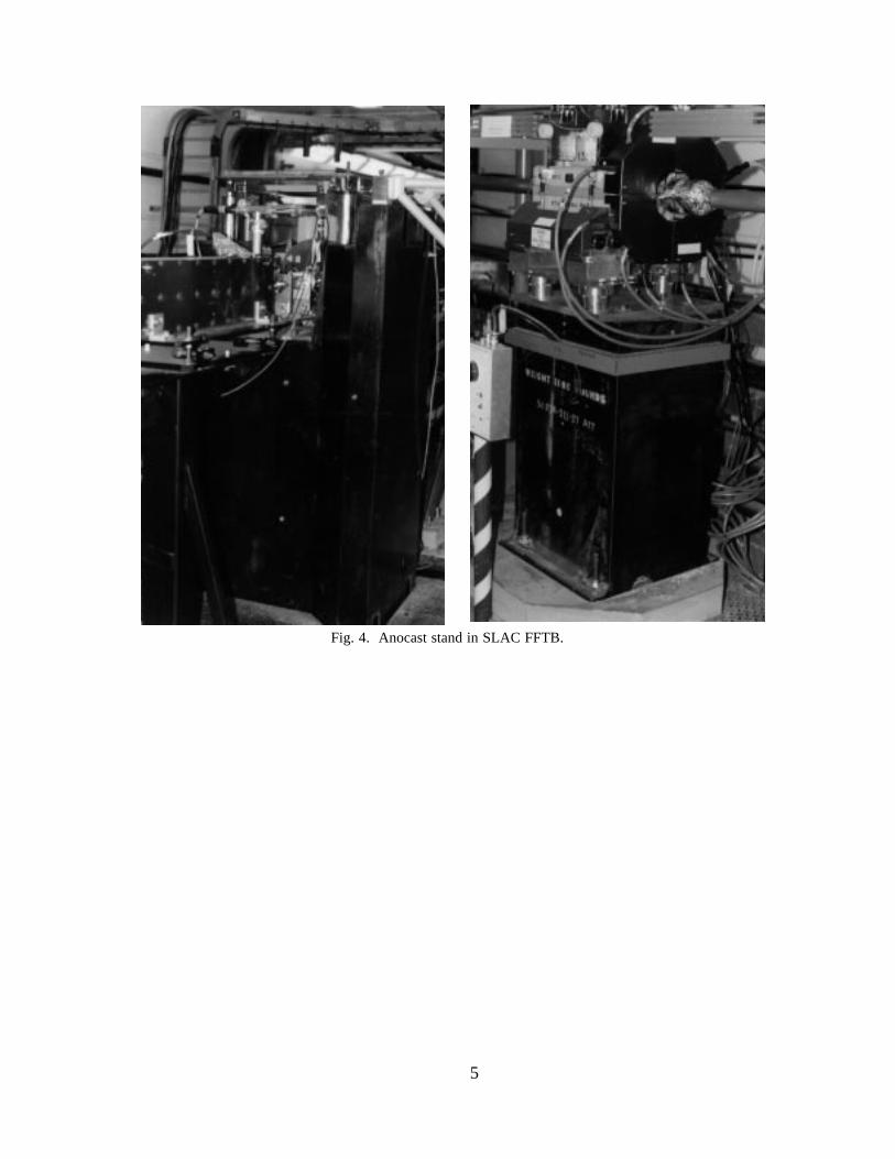
Individual stands are generally used in situations where components are morespread out; e.g., transport lines. The simplest form of stand is a length of pipe with plateswelded to the top and bottom (Fig. 3). The diameter of the pipe is of course a function ofstand height and component load. More sophisticated stands are used at SLAC in theFFTB. These stands are made of Anocast, a granite epoxy which gives the standsthe appearance of a granite block molded to the specifications of the particular application.3
In effect, the Anocaststands become a hybridof stand and girder. Inthe FFTB some Anocaststands support a group ofmagnets while still main-taining the typical crosssection of an individualmagnet stand (Fig. 4).Measurements confirmthat these stands havemuch better dampingqualities of vibrations athigher frequencies thansteel stands. Further-more, their thermal massdampens expansion dueto variations in the am-bient temperatures. Costsfor steel and Anocaststands are comparable.
11.1.2 Manual Ad-justment Systems
All beam compo-nents need to be movedand fixed at accurate lo-cations by adjustmentmechanisms. These sys-tems should include thefollowing design fea-tures:Fig. 3. Individual steel stand.

5
• Adequate alignment precision : for precise adjustibility, the system’s resolution shouldbe ten times the required alignment tolerance.
• Orthogonal motion : there should be no cross coupling between the axes for smalladjustment motions. For large motions, any existing coupling must be predictable.
• Kinematic mount : an overconstrained system induces stress into the support and/orcomponent, resulting in a deformation of the component.
• Stability : the support should provide a stiff base when locked down where incidentalcontact will not cause movement of the magnet. It should also not deform thecomponent during adjustment.
• A small footprint : as real estate is usually at a premium, components must often beplaced very close together.
• Vibrational stiffness : typical ground motion frequencies should not be amplified by thesupport system.
There are two general types of adjustment mechanisms. The most common typeseparates the horizontal adjustment from the vertical degree of freedom. The second typecombines horizontal and vertical adjustments into one system, usually implemented in a sixstrut layout that holds the component in a kinematic suspension. Other implementations arethe CERN Adjuster System and its derivative, the CEBAF 3-D Cartridge, and the SLAC3-D stage.
Fig. 4. Anocast stand in SLAC FFTB.

6
11.1.2.1 One and Two–Dimension Systems
To separate the horizontal from the vertical, a horizontal plane is generated byadjusting the height of three vertical standoffs. In its simplest implementation, the standoffsare either shim stacks or threaded rods. In the case of shim stacks, shim stock is added orremoved until the plate is horizontal and the component at its ideal height, a lengthy, itera-tive process. Where threaded rods are used, the mounting plate rides on three screw nutsthat are threaded on vertically mounted rods. Turning the nuts provides vertical translationsalong the Y–axis and two rotational degrees of freedom, pitch (rotation around the X–axis),and roll (rotation around the Z–axis).
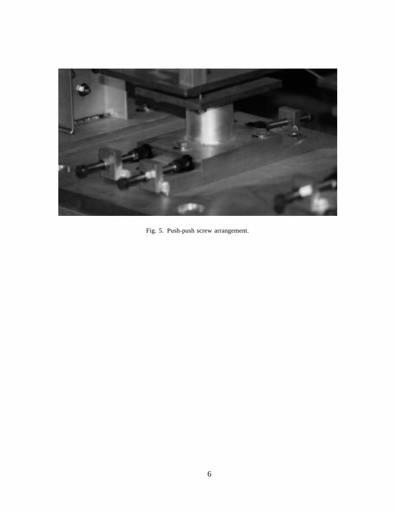
On this horizontal plate slide one or two plates on which the component is mounted.These plates move under the force of adjustment screws to adjust and fix the Z (in beamdirection), X (perpendicular to Z), and yaw (rotation around the Y–axis) degrees offreedom. The adjustment screws are often designed in a push-push arrangement (Fig. 5)with two opposing screws pushing on both sides of the component in a colinear arrange-ment. To achieve a translation, one side is loosened and the other tightened. Tighteningboth screws locks the position. Often the stand has only one sliding plate; in this case, theX and Z adjustments are not independent, since all adjustment screws must be loosened topermit sliding of the plate. Fine adjustment in the orthogonal direction is usually lost, andmust be touched up again. Precise alignment with only a single sliding plate and push-pushscrew arrangement usually requires many iterations.
This basic design can be refined by replacing the above described horizontal andvertical adjuster with more sophisticated variations. The addition of spherical washers be-tween the horizontal plate and the adjustment nuts makes the system move more smoothly.If the system is designed to carry higher loads, machine screw jacks (Fig. 6) are availablethat fit almost any application while still providing fine adjustment motion. Less expensive,but more limited in range, are wedge jack adjusters that are made of two wedges with the
Fig. 5. Push-push screw arrangement.

7
two sloped planes riding oneach other. A horizontal mo-tion pushes the upper wedgehigher on the inclined plane,thereby providing a verticalmotion. Wedge jack adjust-ers are available off the shelfin many load travel combin-ations. The push-push screwarrangement can be im-proved by a turnbuckle/rail-slide design. The two pushscrews are replaced by oneturnbuckle, which providesboth the push and pull force.The fixed end of the turn-buckle can slide on a rail or-iented parallel to the otheradjustment axis in order toallow two-dimensional ad-justments. This design isstill relatively simple andinexpensive, while comply-ing with all the above listedrequirements. To support thegirders in the storage ring ofthe Argonne Photon Source,a combination of wedge jackadjusters (Fig. 7) and turn-buckle-type horizontal ad-justment was used.
11.1.2.2 Three-Dimension Systems
Six-strut system A kinematic suspension canbe created by arranging six adjustable lengthlinks in a 3-D truss. The three vertical strutsadjust and hold the vertical translation, andthe pitch and roll rotations. The three otherstruts (Fig. 8) are placed in the horizontalplane, two in one direction, and the thirdperpendicular. These three adjust and holdthe X and Z translations and the yaw
Fig. 6. Machine screw jack support.
���
���
���
���
���
���������� ���
������3-94
7633A1
���
Fig. 7. Wedge jack adjuster as used in APS.

8
rotation. The orthogonal arrangementof the struts minimizes coupling inmotion. Struts are length-adjustablerigid members with spherical joints ateach end. A strut will support only anaxial load, in axial compression ortension. The spherical joints at eitherend ensure that a strut never exper-iences loads in any other direction.Since all struts are in axial compressionor tension, they provide very rigidsupport.
11.1.2.3 Typical System Implemen-tations
Advanced Light Source (ALS) strut system . All components and girders at the AdvancedLight Source at the Lawrence Berkeley Laboratory are supported by strut systems4
(Fig. 9), as is the Spherical Grating Monochromator at the SSRL. The struts used for thesupport systems are not normal stock items. To avoid the backlash present in all regularspherical joints, the spherical rod end bearings have been squeezed in a controlled way togenerate friction, which only a specific break-away torque can overcome. A shaft collar hasbeen added at the end of each tube into which the rod end bearings thread. A portion of thetube, at each end, is turned down and slit in two directions so the shaft collar will squeeze
Top
Side End
X X
Z
Y YZ
Y YX
3 (Y) Vertical Struts2 (X) Lateral Struts1 (Z) Lateral Strut
3-94 7633A2
Fig. 8. Kinematic suspension.
Figure 9. ALS strut supports. Photo courtesy of Lawrence Berkeley Laboratory, University of California.

9
Fig. 10. ALS 5-ton machine screw jack strut. Fig. 11. ALS 20-ton machine screw jack strut.Photo courtesy of Lawrence Berkeley Laboratory,University of California.
Photo courtesy of Lawrence Berkeley Laboratory,University of California.
the female thread against the male thread of the rod ends to remove any backlash in thethreads. The rod end bearings are all right-hand threads with one coarse thread and theother a fine thread, creating a differential threaded device which allows very high resolutionadjustments. For the support of heavy loads, the tube and differential threads are replacedby an appropriately rated machine screw jack (Figs. 10, 11).
CERN cartridge . The CERN AdjusterSystem5 consists of three cartridges thatutilize a combination of the principles in thetwo styles discussed above. The improve-ment over the first style mechanism is thatthe sliding feature is replaced by the threevertically-oriented links of the kinematicsuspension. The first or main cartridgeworks as follows (Fig. 12): the piston-ended link pivots in a socket at the bottom ofthe base and floats within a hollowcylindrical projection from that base. At thetop, the link pivots in and supports a capwhose outer skirt drapes over the cylindricalprojection. The device to be positioned is
���������������
������
���������
����
������������ ������������
������������
3-947633A3
Fig. 12. CERN cartridge adjuster.

10
placed on this cap. The cap is driven horizontally by four bolts threaded through the skirtof the cap, which press against four flats machined into the cylindrical projection. Lateraland longitudinal adjustment is achieved with one of these pairs of opposing push-pushscrews. As one bolt is loosened and the opposite bolt tightened, the cap glides easily,rocking on the vertical link. The sockets in which the link is mounted consist of cylindersin the base and cap that are filled with urethane rubber.
Four screws in the base and four screws in the cap drive in and out of this volume,compressing the rubber and driving the link or the cap higher or lower respectively,providing the vertical adjustment. The second cartridge lacks one set of opposing screwsand the third cartridge lacks both sets, leaving no restraint on the cap, allowing it to floatand provide only vertical adjustment. The three cartridges are placed in a triangular patternwith the set of opposing screws of the second cartridge parallel to one set of screws inthe main cartridge. Use of all three cartridges provides pitch, roll, and yaw adjustment.One advantage of the CERN Adjuster System over the kinematic suspension is that thereis much less coupling between the adjustments, so that alignment is more easily obtained.
CEBAF cartridge The CEBAF cartridge6 uses many of the features of the CERN AdjusterSystem design. Three identical cartridges are attached to a stand through specially boredmounting holes. Each cartridge consists of a vertical cylinder and a cap (Fig. 13). Thedevice to be adjusted is fastened to the caps of the three cartridges. The hollow, verticalcylinder has two opposing flats on its outer wall at the top, and a threaded hole in itsbottom, into which is threaded a set screw. Turning this screw raises the cap, via a verticalrod through the cylinder. Lateral adjustment is by a pair of opposing screws through theskirt of the cap, registering against the flats on the cylinder. The cap glides over easilywhile rocking on the vertical rod. The cartridges are mounted on the stand such that theflats on two cylinders are parallel to each other and the flats on the remaining cylinder areperpendicular to the other two, providing lateral, longitudinal, and yaw adjustment. Withthis orientation, all degrees of freedom are constrained with no overconstraint. Lockingof the movement of all screw threads is provided by locknuts.
SLAC damping ring girder support This designcontains the most basic adjustment system con-struction elements, a push-push screw arrangementcombined with a threaded rod7 (Fig. 14). The girderis supported by three feet. Each foot’s baseplate isbolted and grouted to the floor in an approximatelyhorizontal position. Atop this baseplate sits a sliding
�
��
�
��
����
������
�
�
�����
3-947633A4
�����
��Fig. 13. CEBAF cartridge adjuster.
���������
����
���������������������
��
����������
3-947633A5
Fig. 14. SLAC Damping Ring girder support.

11
plate that can be moved relative to the baseplate by the force of a two-dimensional push-push screw arrangement. A short fine-threaded rod of substantial diameter is mounted tothe sliding plate at its center. A cap-shaped nut, riding on the threads over the top of therod, provides the vertical adjustment. The girder is mounted to this nut in a way whichprevents any horizontal backlash, while still permitting it to be turned. The system is lockedin the horizontal dimension by a bolt holding the sliding plate to the baseplate, and in thevertical dimension by a set screw which prevents the cap nut from turning. While thissystem allows relatively high resolution adjustment of heavy loads, the total system issignificantly overconstrained, and must therefore be operated with great caution.
SLAC Final Focus girder support This design is similar to the Damping Ring supports,but avoids the overconstraints8 (Fig. 15). The push-push screw arrangement is replacedby one-dimensional stages: two feet have stages oriented for lateral adjustment, while thestage at the third foot provides longitudinal motion. To decouple the cross-motion betweenstages, the supports are fixed to the girder in only one horizontal dimension, which isaccomplished by a rail slide system. The vertical adjustment is functionally the same as onthe support discussed above.
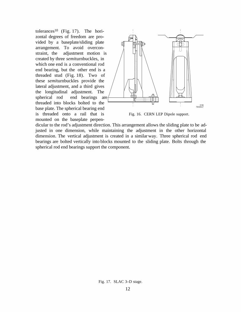
CERN LEP dipole support This system9 can provide kinematic support to a wide varietyof applications, from small magnets to heavy girder modules. The general idea andfunctionality are taken from the CERN cartridge design, but with the vertical adjustmentreplaced by an adjustable-length link (Fig. 16). To minimize motion correlation, the link ismade as long as possible, subject to the restraints of the specific application.
SLAC 3-D stage This is an adjustment system tailored to support a variety ofcomponents, from small quadrupoles to long narrow bends that are to be positioned to tight
Fig. 15. SLAC Final Focus girder support.
12
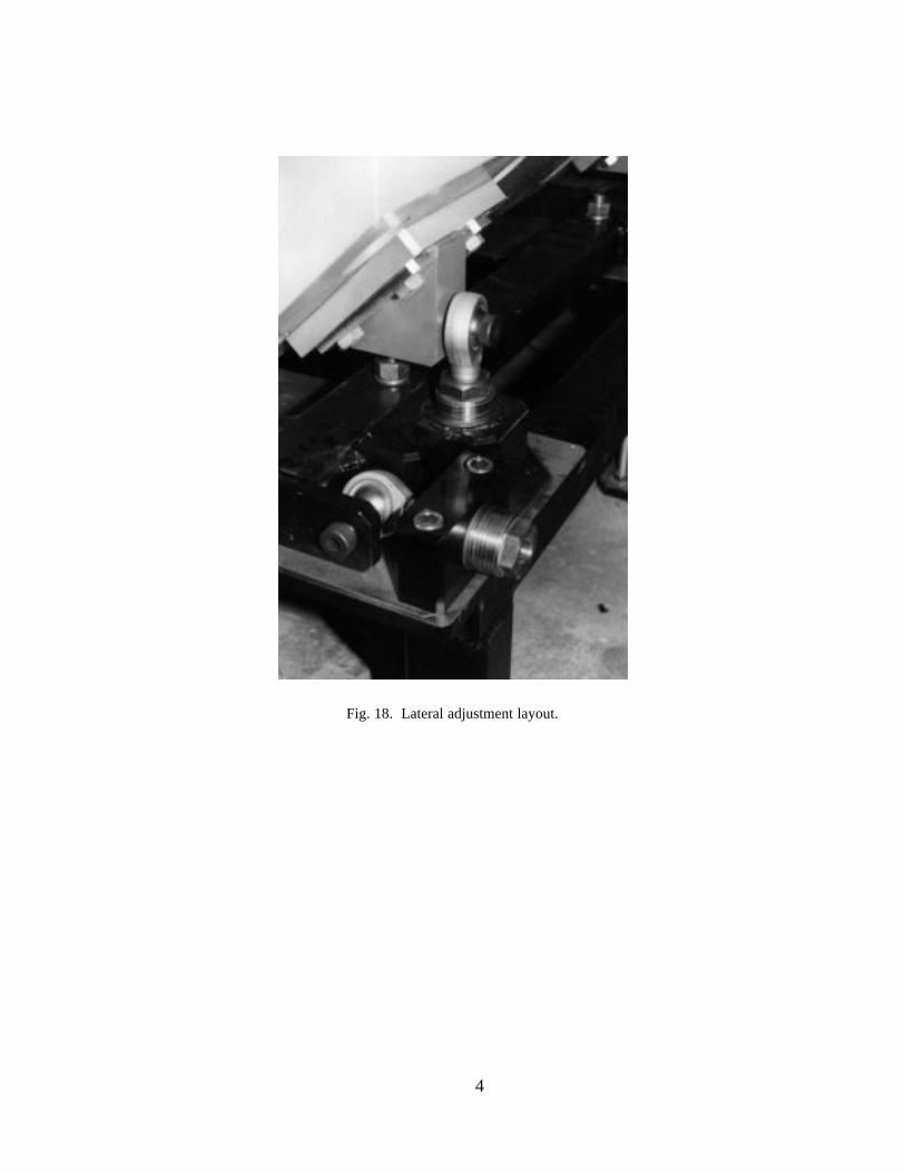
tolerances10 (Fig. 17). The hori-zontal degrees of freedom are pro-vided by a baseplate/sliding platearrangement. To avoid overcon-straint, the adjustment motion iscreated by three semiturnbuckles, inwhich one end is a conventional rodend bearing, but the other end is athreaded stud (Fig. 18). Two ofthese semiturnbuckles provide thelateral adjustment, and a third givesthe longitudinal adjustment. Thespherical rod end bearings arethreaded into blocks bolted to thebase plate. The spherical bearing endis threaded onto a rail that ismounted on the baseplate perpen-dicular to the rod’s adjustment direction. This arrangement allows the sliding plate to be ad-justed in one dimension, while maintaining the adjustment in the other horizontaldimension. The vertical adjustment is created in a similar way. Three spherical rod endbearings are bolted vertically into blocks mounted to the sliding plate. Bolts through thespherical rod end bearings support the component.
����
��
��
�����
3-947633A17
Fig. 16. CERN LEP Dipole support.
Fig. 17. SLAC 3–D stage.

13
DESY PETRA single component support system This system11 hasbeen used to support quadrupoleson single stands and long dipoleson two single stands at eithermagnet end in the PETRA ring. Theunderlying scheme is now widelyused in other machines at DESY.Shown below in Fig. 19 is aquadrupole sitting with three padson three vertical screws that provideheight, roll, and pitch adjustments.In the horizontal plane, two strutsallow motion perpendicular to thebeam. No adjustment capabilityalong the beam axis is provided. Tocreate a kinematic mount betweenthe pads and screws, one screwhead is resting in a groove, whilethe other two pads are flat.
11.1.3 Motorized AdjustmentSystems
SLAC FFTB magnet positionersThe FFTB magnet positioners12
differ from conventional positioningstages used in instruments and ma-chine tools. The mechanism is de-signed to support loads exceeding1 ton, while still providing smooth
motion, free of hysteresis, at the micron level. The design is simple and sufficiently reliablefor large scale use in the remote positioning of hundreds of magnets. Conventionalcrossed-slide leadscrew positioningstages are not appropriate for thisapplication. High-resolution piezo-electric positioners13 cannot meet theload and range requirements. Theremote magnet positioning mountsused in the FFTB kinematicallysupport the magnets on roller cams.The magnet rests under gravity in acradle formed by the cams(Fig. 20). This type of kinematicsupport is similar to the KelvinClamp14 used in laboratory optics
Fig. 18. Lateral adjustment layout.
3-947633A18
Fig. 19. DESY PETRA support system.

14
and instrumentation. The V–blocks andflat plates fixed to the magnet make pointor line contact with the outer bearingraces of the roller cams. Rotation of theeccentric camshafts shifts the magnetposition. This type of kinematic support,where the number of contact pointsbalances the number of degrees of spatialfreedom, has the advantage of avoidingall free play between the magnet andmount. The magnet always rests incontact with all of the supporting cams,regardless of their position. No precisemechanical dimensions are needed toinsure zero play. No clamping forces, other than gravity, can distort the magnet’s shape.The magnet can be removed from the mount and replaced without realignment. Duringoperation, only the inner eccentric shaft of a support cam rotates under motor control. Theouter cam bearing race remains in contact with the magnet as shaft rotation lifts the magnet.In such a system, failure of the control system will only cause the cam to cycle aroundagain. Magnet motions are strictly bounded by the design geometry. Limit switches are notneeded for over-travel protection. All support cams are arranged so that gravity applies aload torque to each cam shaft drive train. This torque removes all backlash, except at theextremes of cam lift. All parts move by pure rolling motion, and are free of the hysteresistypical of intermittent and reversing sliding motion. This mount can adjust the horizontal
� ��3-94 7637A6
Fig. 20. Magnet positioning mount with roller cams.
Fig. 21. FFTB magnet remote positioner.

15
and vertical position of the magnet, as well as the magnet’s roll angle around the beam axis.The magnet’s longitudinal position along the beam line, as well as its alignment to the beamdirection in this implementation are fixed in the support mount, and not remotelyadjustable. Figure 21 shows the three-motor positioning mount used to support FFTBquadrupole magnets. Kinematic roller cam supports can be applied to a variety ofgeometries. The barrel containing the final triplet of quadrupole lenses for the StanfordLinear Collider is supported on five roller cam supports. This 5-m-long 6-ton assembly isremotely adjustable in pitch and yaw, as well as roll, vertical, and horizontal position.
ESRF servo-controlled jacks Predicted ground motion of more than 1 mm per year led tothe development of a remote vertical alignment system. A computer-controlled hydrostaticleveling system was installed in the storage ring with three measurement stations on eachgirder. These girders are kinematically supported by three vertical motorized screw jacks,which are interfaced to the control system. The horizontal adjustment is provided by a gear-driven X-Z stage mounted on top of the vertical jacks.15 First results indicate that it takesabout two minutes to map the entire ring, and then only two hours to vertically align allgirders.16
11.2 Alignment
A Survey and Alignment team’s charter in building light sources is the physicalpositioning of all machine components, including magnets, insertion devices, detectors,and diagnostic devices, according to layout specifications. The task of positioning magnetscan be broken down into six major subtasks:
• Survey reference frames : the first step is to define and physically establish a surveycoordinate system appropriate to the project site and size. Control monuments areestablished to represent this reference grid.
• Layout description reference frame : the beam line is designed and specified in a latticecoordinate system. Coordinate transformations, including rotations andtransformations, need to be defined to relate this to the survey reference frame.
• Fiducialization : the fiducialization of a component relates its effective magnetic orelectrical centerline to external reference points that are accessible to subsequent surveymeasurements.
• Prealignment of girders : after components and vacuum chambers are mounted on agirder, they are aligned relative to a girder coordinate system.
• Absolute positioning : girders are positioned with respect to the global reference grid.
• Relative positioning : local tolerances are achieved by the relative alignment of adjacentcomponents.
11.2.1 Survey Reference Frames
The goal is to define a computational reference frame—a mathematical model of thespace in which the surveyor takes his measurements and performs his data analysis.Transformation algorithms and parameters between the surveying space and the machinelayout coordinate system must be defined.

16
11.2.1.1 Surveying Space
Ancient civilizations realized that the earth is round, and geodesy was born whenthe Greek Eratosthenes (born 276BC) first attempted to determine its size.17 The earth isactually of a more complex shape, the modeling of which is not easy. Three surfaces are ofimportance to the geodesist studying the shape of the earth:i) The terrain surface is irregular, departing by up to 8000 m above and 10000 m
below the mean sea level.
ii) The geoid is the reference surface described by gravity; it is the equipotential surface atmean sea level that is everywhere normal to the gravity vector. Although it is a moreregular figure than the earth’s surface, it is still irregular due to local mass anomaliesthat cause departures of up to 150 m from the reference ellipsoid. As a result, thegeoid is nonsymmetric and its mathematical description nonparametric, rendering itunsuitable as a reference surface for calculations. It is, however, the surface on whichall survey measurements are made as almost all survey instruments are set up withrespect to gravity. Even the satellites now used for GPS surveys follow orbitsdetermined by gravity.
iii) The spheroid or ellipsoid is the regular figure that most closely approximates theshape of the earth, and is therefore widely used in astronomy and geodesy to modelthe earth (Fig. 22). Being a regular mathematical figure, it is the surface on whichcalculations can be made. Nevertheless, inperforming these calculations, account must betaken of the discrepancy between the ellipsoidand the geoid. The deflection (or deviation) ofthe vertical is the angle of divergence betweenthe gravity vector (normal to the geoid) and theellipsoid normal (Fig. 23). Several differentellipsoids have been defined and chosen thatminimize geoidal discrepancies on a globalscale, but for a survey engineering project, it issufficient to define a best-fit local spheroid that
North
South
Geoid
ReferenceEllipsoid
3-947633A7
Fig. 22. Spheroid (ellipsoid) and geoid.
����������
PlumbLine
EquipotentialSurface
Geoid
Ellipsoid
3-94 7633A8
P
Terrain
Deflectionof the Vertical
GravityVector
EllipsoidalNormal
Fig. 23. Spheroid normal and gravity.

17
spheroid that minimizes discrepancies only in the local area. Whatever ellipsoid ischosen, all survey measurements must be reduced to the ellipsoid before computationscan proceed. This reduction of observations to the computational surface is an integralpart of position determination;18 the equations can be found in most of the geodeticliterature, e.g., in Leick.19
11.2.1.2 Surveying Coordinate System
Computations with spheroidal (geographical) coordinates latitude φ, longitude λ ,and height h are complex. They are also not very intuitive: when using spheroidal heights,it can appear that water is flowing uphill. Especially in survey engineering projects,coordinate differences should directly and easily translate into distances independent oftheir latitude on the reference spheroid. Therefore, it is desirable to project the spheroidalcoordinates into a local Cartesian coordinate system or, going one step further, to projectthe original observations into the local planar system to arrive directly at planar rectangularcoordinates.
A transformation is required to project points from a spheroidal surface to points ona plane surface. Depending on the projec-tion, certain properties of relationship (distance,angle, etc.) between the original points aremaintained, while others are distorted. It issimply not possible to project a sphericalsurface on to a plane without creatingdistortions18 (Fig. 24), but since thesedistortions can be modeled mathemat-ically, it is possible to correct derivedrelationships, such as distances, angles, orelevations. This situation can be vividlyshown on the example of the projection of leveled elevations onto a planar coordinatesystem (Fig. 25). Table 1 shows the projection errors as a function of the distance fromthe coordinate system’s origin. Notice that the deviation between plane and sphere isalready 0.03 mm at 20 m.
Since further discussion here is focused on small machines, geodetic issues such asthe earth’s curvature and gravity anomalies can be excluded, thus simplifying themathematics to planar Cartesian coordinate arithmetic.
3-947633A9
Fig. 24. Projection of sphere onto a plane.
Table 1. Curvature correction, plane tosphere or spheroid.
Distance[m]
SphereHS [m]
SpheroidHE [m]
20 0.00003 0.00003
50 0.00020 0.00016
100 0.00078 0.00063
1000 0.07846 0.06257
10000 7.84620 6.25749
25000 49.03878 39.10929
Plane
Spheroid
Sphere
HEHS
3-947633A10
Fig. 25. Curvature correction.

18
11.2.1.3 Survey Networks
The surveying coordinate system is physically represented by monuments whosecoordinates are determined using conventional trilateration or triangulation methods or, forlarger size projects, satellite methods like the Global Positioning System.20
Surface network In order to achieve the absolute tolerance and the circumference re-quirements, a surface network with pillar-type monuments (Fig. 26) must usually beestablished. Traditional triangulation and trilateration methods (Fig. 27) or GPS surveyscan be applied to measure the coordinates of the monuments and of tripods over the transfershafts or sightholes. Differential leveling of redundant loops is the standard method todetermine the vertical coordinates. Proper reduction of measured distances also requiresaccurate elevation difference data.
Using state-of-the-art equipment in a small trilateration network with good intervisibility ofmonuments can yield standard deviations for the horizontal coordinates in the rangeof 2 mm + 1 ppm. In medium size applications, it has been shown that GPS, combinedwith terrestrial observations and careful control of the antenna eccentricities (GPS, too, hasits fiducialization problems), can yield positional accuracies of about 2 mm.21
Trigonometric and differential leveling are the only accurate methods to determineelevations; both methods yield the same accuracies—approximately 1 mm for networkssmaller than 2 km.
Fig. 26. SLAC–SLC pillar monument.

19
Tunnel The tunnel horizontal netis usually tied to the surface netby optically or mechanically cen-tering a tripod-mounted transla-tion stage on the surface over amonument in the tunnel through asurvey shaft. These tunnel net-works are usually long and nar-row (Fig. 28), and incorporatepoints beneath the shafts as con-nections to the surface net. Thefloor marks can be 2-D (horizon-tal only) or 3-D: common designsare the SLAC 2-D marks, theDESY-HERA 3-D reference cupsor the standard 1.5 inch floorcups and magnet mounts. Some
kind of tripod or column-like monopod is used for the instrument setup. The SLAC setup(Fig. 29) is designed to accommodate slopes of up to 15°; the HERA design is moreoptimized towards efficiency, virtually eliminating the task of centering instruments andtargets over monuments.22 The elevation of the instrument above the 3-D reference cup isknown very accurately, which facilitates 3-D mapping with theodolites.
11.2.2 Layout Description Reference Frame
The layout description of every machine component is given in a document calledthe design lattice (for details, refer to Chapter 2, Lattices) which defines the physicalparameters of each machine component, including its ideal position.
For every new machine, various computer programs, e.g., TRANSPORT,23 areused to simulate the path of the particles. Model components bend, focus, or defocus theparticles as they traverse the electromagnetic fields they encounter. Component parametersare manipulated to keep them on the intended trajectory, and to qualify the beam’scharacteristics. The result of such simulations is a sequential listing of the designcomponents and their parameters. Most commonly, the parameters for the beginning of themagnetic length of a component and of the following drift space are listed, including the sixdegrees of freedom for the beam following coordinate system. In addition, a magnet’s fieldstrength, and, if applicable, its bending angle are given.
Based on experience and the results of lattice simulation runs, position tolerancesare determined for each magnetic component and are attached to the lattice specifications
MON40
MON30
MON20
MON10
DR10
DR20DR30
L10
MON00L20
DR40
3-94 7633A19
Fig. 27. Example of surface network (Argonne APS).
3-94 7633A11
Survey Station
Beamline
Fig. 28. Tunnel network layout (Argonne APS).

20
Fig. 29. SLAC tripod setup.
(see Wiedemann24 for a discussion of the effects of magnet alignment errors). Theindividually specified parameters are usually the maximum permissible displacements in thedirection of the three coordinates and the rotation around the longitudinal axis. Thetolerance specifications should distinguish between absolute and relative positioning.The absolute positioning tolerance defines a maximum global shape distortion by specify-ing how close a component must be to its ideal location, whereas the more importantrelative tolerance defines the alignment quality of adjacent components. The tolerancedefinition should also state the required level of confidence, and whether or not the randomdistribution is truncated.
Surveying measurements, if done carefully with well-calibrated sensors, will showa typical Gaussian distribution, including entries outside the chosen confidence level.Achieving the equivalent of the mathematical truncation requires a means to identify“outliers” and a method to add independent redundant observations. Traditionally, thestochastic computations in surveying are based on a 1σ confidence level. Achieving the
same result on a 2σ confidence level requires an exponential increase in survey effort.The relationship between the surveying and lattice coordinate systems is defined as
a transformation matrix.25
11.2.3 Fiducialization
Fiducialization is a fancy name for relating the effective internal electromagneticaxes of a component to external marks that can be seen or touched by instruments. It isthese reference marks that are then aligned onto their nominal coordinates. It is thereforeobvious that the measurement of the magnetic axis to the fiducial marks must be done withat least as much care as the final positioning.

21
Magnets in storage rings and injection systems have, for the most part, been madewith ferromagnetic poles, which are traditionally used as the references for externalalignment fiducials.26 (For more details, refer to Chapter 5, Magnet Design.) It isassumed that the magnetic field is well-defined by the poles, but this assumption fails in thepresence of saturation, and is invalid for superconducting magnets, which have no tangiblepoles. Furthermore, since the poles of an iron dipole are never perfectly flat or parallel,where is the magnetic midplane?27 For quadrupoles, sextupoles, and higher ordermagnets, there is no unique inscribed circle that is tangent to more than three of these poles;where then is the centerline?
The only way to avoid these problems is to use magnetic field measurement (fordetails, refer to Chapter 7, Magnetic Measurements) to establish fiducials. This hasalready worked successfully for a number of projects, including the alignment of multiplepermanent quadrupoles in drift-tube linac tanks in Los Alamos,28 the SLC/SLDsuperconducting triplet quadrupoles, the HERA superconducting proton ring magnets,29
and the Final Focus Test Beam at SLAC30 (Fig. 30).
11.2.4 Prealignment of Girders
Girders are commonly used in light sources to support components and the vacuumchamber of one lattice cell of a common plane. These girders are preassembled in a factorybefore they are transported into the tunnel. After an initial component prealignment, themagnets are split and the vacuum chamber inserted. The chamber can be positioned using
Fig. 30. Fiducialization setup of FFTB magnets at SLAC.

22
gauge blocks held against the magnet pole tips, or optically. If no nonelastic girderdeflections are expected during transportation, a fine position alignment is also made.150 µm is a typical tolerance for the relative positioning of magnets.
Usually, prealignment bays are set up emulating a generic beam line position; i.e.,the girder is set up and supported in exactly the same way as it will be in its final beam lineposition. Traditional optical tooling techniques (Fig. 31) or industrial measurement systemmeasurements (Fig. 32) can provide the required accuracy.
11.2.5 Absolute Positioning
Efficient computer-aided methods and procedures have been developed to increasepositioning productivity, accuracy, and reliability. These techniques have been tested andproven in the alignment of many machines, including the ALS and APS light sources andthe SLC, HERA, and LEP colliders. The absolute positioning can be subdivided into foursteps :
Step 1. “Blue line” survey on the tunnel floorStep 2. Rough absolute positioning of girders in tunnelStep 3. Fine absolute positioning of girdersStep 4. Quality control survey
11.2.5.1 Blue Line Survey on the Tunnel Floor
In preparation for the installation of the support systems, a “blue line” survey isperformed to lay out the anchor bolt positions. This is done from the tunnel traverse pointsusing intersection methods or, more efficiently, utilizing tachymetry with instruments likethe Leica TC2002 or the Chesapeake Lasertracker.31 A relative accuracy with respect to themonuments of 5 mm can be easily achieved.
Fig. 31. Prealignment with optical tooling (Argonne APS). Photo courtesy of Argonne National Lab.

23
11.2.5.2 Rough Absolute Positioning of Girders in Tunnel
After the blue line survey, the anchors are set and the prealigned monoliths orgirders installed, but with the anchor bolt nuts only “hand tight,” and the girders’ adjust-ment systems set to midrange to ensure the full adjustment range remains available for finepositioning. This adjustment system should not be used to correct the misalignment of thesupport system itself; instead, the support system is prealigned by tapping it into positionutilizing the slack between anchor bolts and support structure. To determine the actualpositions of the supports, direction and distance measurements from monuments are taken,from which actual coordinates are calculated and compared to the ideal coordinates, yield-ing the adjustment values in the global coordinate system orientation. Before these correc-tions can be applied in the field, they must be transformed into the local coordinate systemof the supports. This process can be greatly accelerated by reducing the data on line in thefield, providing immediate in situ coordinate feedback. High accuracy Total Stations, likethe Leica TC2002 or the Chesapeake Lasertracker, interfaced to powerful field computersmake this possible. The required software has been developed at SLAC and tested withgreat success in the alignment of the rebuilt SLC Damping Rings and Final Foci.
11.2.5.3 Fine Absolute Positioning of Components
The girders are first aligned vertically: using differential leveling, the girder is set toits ideal elevation with zero pitch and roll. The horizontal positions of the girders are set
Fig. 32. Prealignment with industrial measurement system. Photo courtesy of Lawrence BerkeleyLaboratory, University of California.

24
relative to the tunnel monument system. In principle, the alignment technique here is thesame as described above. However, the TC2002 in the on-line feedback loop does notyield the required accuracy; only a laser tracker does. If a laser tracker is not available,traditional time-intensive triangulation techniques will effectively produce the same result.
11.2.5.4 Quality Control Survey
After the absolute positioning of girders is completed in some logically functionalsection of the machine, a complete resurvey of this section should be conducted to verifythe results. Quality control is better achieved by the use of independent procedures, ratherthan the repetition of the same procedure by different teams. This provides the trulyindependent observations necessary to check the accuracy of the initial survey. Resurveyswith the same methodology do not provide this independent check, and rarely detect theinfrequent data gathering errors occurring with today’s electronic instruments and fieldcomputers.
11.2.6 Relative Positioning(Smoothing)
The accuracy obtained in theabsolute positioning step is the quadraticsum of many random errors (surface net-work, transfer of control through penetra-tion shafts, tunnel control, magnet fiducia-lization, magnet layout, etc.) plus the linear sum of any residual systematic errors:instrument calibration, forced centering, set up over control points, velocity correction oflight, horizontal and vertical refraction, etc. A cigar-shaped error envelope is typical for theabsolute alignment of a beam line. (In this context, beam line refers to a section of astorage ring, and not to the tangential port which conveys the synchrotron radiation fromthe storage ring to the experimental station.) The error envelope is a minimum (but neverzero) at the control points, and grows to reach a maximum midway between two successivecontrol points (Fig. 33). The measured reference line oscillates somewhere within thiserror envelope. Its absolute position cannot be pinned down any more precisely than thesize of the error envelope, with deviations within this envelope being statisticallyinsignificant. However, within this absolute error envelope, relative errors betweenadjacent magnets should be smaller: the major error sources equally affect the positioningof adjacent components, with the result that relative alignment accuracies are significantlyhigher than absolute alignment accuracies. Consequently, successive surveys will revealreference lines of different shape whose absolute position floats randomly within the cigar-shaped error envelope. An important implication of this is that the absolute comparison ofindependent surveys “would be a nonsense”32 when trying to evaluate differences smallerthan the width of the absolute error envelope. If attempts are made to proceed with finalabsolute alignment, the “nonsense” occurs when successive rounds of survey andalignment do not converge, i.e., do not result in reducing the magnitude of themisalignments. All that is happening in this case is that the components are being movedback and forth within the error envelope.
Absolute Error Envelope
Ideal Reference Line
12-927334A3
Actual Reference CurveA B
Fig. 33. Absolute positioning error envelope.
25
Because of these problems, the absolute positioning technique is not well suited toachieving the final relative position tolerance. This problem was first recognized when thesize of machines increased rapidly, stretching the distance between first-order monumentsfrom 30 m (CERN-ISR) to 1200 m (CERN-SPS), and thereby magnifying and renderingvisible this effect. To overcome the problem, techniques were developed to separate relativedisplacements from the absolute trend curve—techniques which we now refer to as“smoothing.” After smoothing, the final distribution of residuals is examined by Fourierdecomposition-type analysis to ensure that no significant amplitudes occur at the betatronfrequency.
11.2.6.1 SLAC–Style Smoothing
The alignment tolerances set out for the SLC show how smoothness is moreimportant than absolute positioning for beam transport.33 For this machine, a globalpositioning envelope is set to ±5 mm for every arc magnet, while the relative alignment ofthree adjacent magnets should be within ±0.1 mm.
The pitched and rolled sausage-link beam line formed by the arc magnets makes thismodeling particularly difficult. The absolute design shape of the path is a series of curvesand straight sections in pitched and rolled planes. This form does not readily lend itself tofitting with polynomials or splines. The large coupling of the horizontal and vertical alsoprevents the separation of smoothing operations into two components.
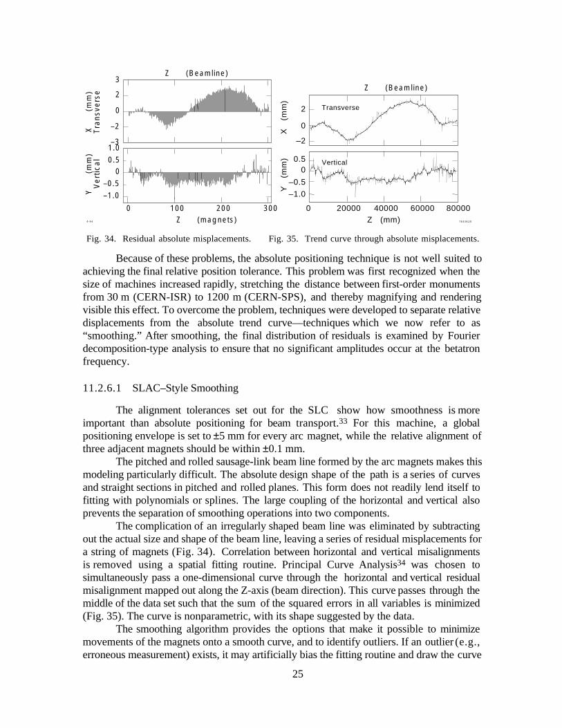
The complication of an irregularly shaped beam line was eliminated by subtractingout the actual size and shape of the beam line, leaving a series of residual misplacements fora string of magnets (Fig. 34). Correlation between horizontal and vertical misalignmentsis removed using a spatial fitting routine. Principal Curve Analysis34 was chosen tosimultaneously pass a one-dimensional curve through the horizontal and vertical residualmisalignment mapped out along the Z-axis (beam direction). This curve passes through themiddle of the data set such that the sum of the squared errors in all variables is minimized(Fig. 35). The curve is nonparametric, with its shape suggested by the data.
The smoothing algorithm provides the options that make it possible to minimizemovements of the magnets onto a smooth curve, and to identify outliers. If an outlier (e.g.,erroneous measurement) exists, it may artificially bias the fitting routine and draw the curve
2
0
–2
0 100 200 300
0.50
–0.5–1.0
X
(mm
)T
ran
sve
rse
Y
(mm
)V
ert
ica
l
1.0
Z (magnets)
Z (Beamline)
–3
3
0 20000 40000 60000 80000
0.50
–0.5
–1.0
7633A204-94
2
0
–2
Z (mm)
Vertical
Transverse
Y
(m
m)
X
(m
m)
Z (Beamline)
Fig. 34. Residual absolute misplacements. Fig. 35. Trend curve through absolute misplacements.
26
curve away from the general neighborhood trend. For this reason, a robustness estimator isincluded in the modeling program to weight out these points.
One improvement was suggested through experience. This involved theindependent weighting of points, so that a small area of magnets can be “patched in” toexisting elements. Other improvements made it possible to deal with irregularly spaced andpatterned beam line layouts.
11.2.6.2 CERN–Style Radial Offset Smoothing
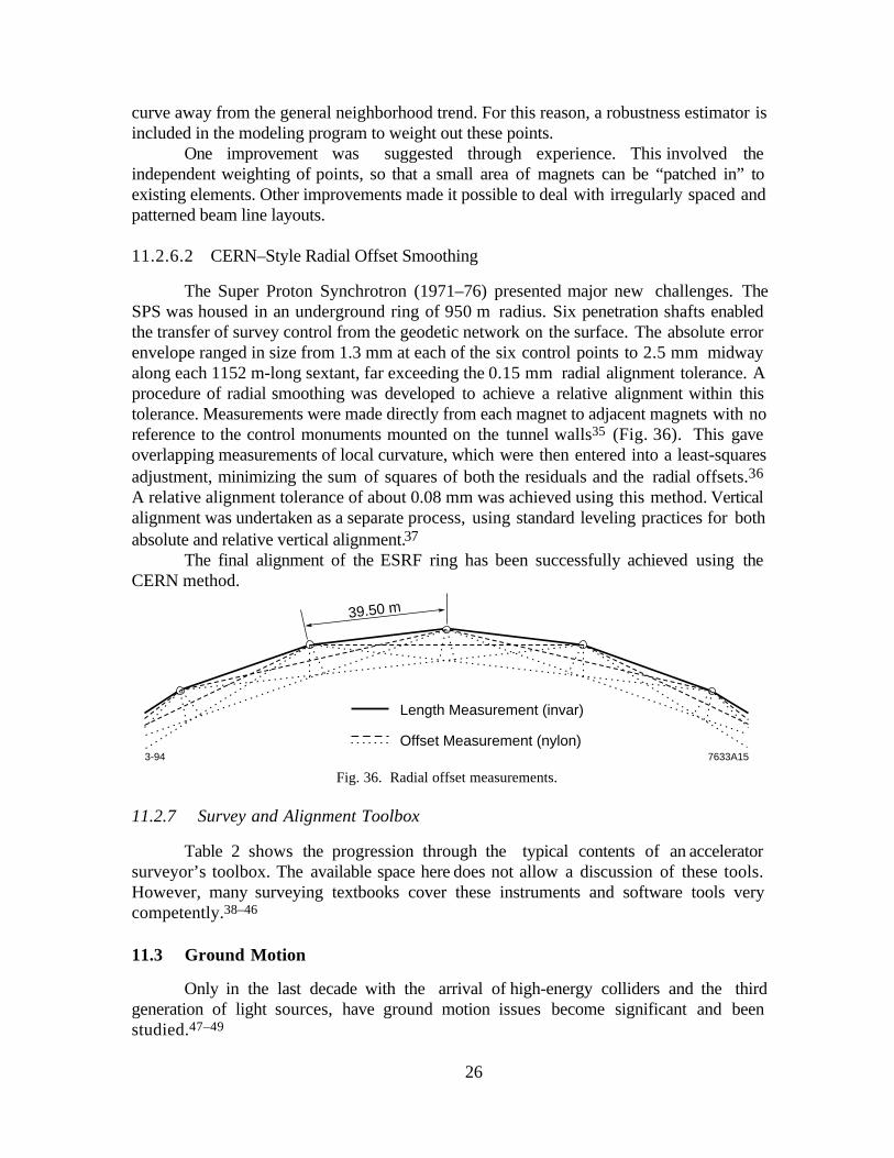
The Super Proton Synchrotron (1971–76) presented major new challenges. TheSPS was housed in an underground ring of 950 m radius. Six penetration shafts enabledthe transfer of survey control from the geodetic network on the surface. The absolute errorenvelope ranged in size from 1.3 mm at each of the six control points to 2.5 mm midwayalong each 1152 m-long sextant, far exceeding the 0.15 mm radial alignment tolerance. Aprocedure of radial smoothing was developed to achieve a relative alignment within thistolerance. Measurements were made directly from each magnet to adjacent magnets with noreference to the control monuments mounted on the tunnel walls35 (Fig. 36). This gaveoverlapping measurements of local curvature, which were then entered into a least-squaresadjustment, minimizing the sum of squares of both the residuals and the radial offsets.36
A relative alignment tolerance of about 0.08 mm was achieved using this method. Verticalalignment was undertaken as a separate process, using standard leveling practices for bothabsolute and relative vertical alignment.37
The final alignment of the ESRF ring has been successfully achieved using theCERN method.
39.50 m
3-94 7633A15
Length Measurement (invar)
Offset Measurement (nylon)
Fig. 36. Radial offset measurements.
11.2.7 Survey and Alignment Toolbox
Table 2 shows the progression through the typical contents of an acceleratorsurveyor’s toolbox. The available space here does not allow a discussion of these tools.However, many surveying textbooks cover these instruments and software tools verycompetently.38–46
11.3 Ground Motion
Only in the last decade with the arrival of high-energy colliders and the thirdgeneration of light sources, have ground motion issues become significant and beenstudied.47–49

27
Ground motion is conveniently categorized into that due to nature and that due toman. Natural ground motion excites movements with long periods, seconds to years, whilemanmade ground motion, having far less energy content, is caused locally and generallyhas frequency components from a few to 50 Hz.50
11.3.1 Natural Sources
The main natural sources are:
• Ground settlement Every new construction project experiences some ground settle-ment. The effects can be minimized by building in areas of competent soil, byminimizing terrain disturbance, and by maintaining ground water levels.
• Tectonic motion Relative motion across a fault can reach several centimeters per year.Since almost all active faults are mapped, it should be possible to avoid these faults.However, there are still many unknown faults (e.g., fault lines discovered at SLACduring the Loma Prieta earthquake51 in 1989) that could generate ground motion effectsat an unknown later time.
Table 2. Typical tools in an accelerator surveyor’s toolbox.
Hardware tools Software tools
Geodetic instrumentsTheodoliteTotal stationLevelPlummetEDMDistinvarDistometer
Optical toolingJig transitSpirit levelAlignment telescope
InterferometryPhotogrammetric equipmentCoordinate measuring machine
StationaryPortable
Dial gauges
Laser tracker
Industrial measurement systemForced centering systemTargeting systems
Integrated databaseData collection routinesRaw data reductionAnalysis input mergingBlunder detectionNetwork adjustments:
1-, 2-, or 3-dimensionUnconstrained datumOverconstrained datum
Bundle adjustmentsGraphical outputCoordinate database
Data analysisCoordinate transformationsDeformation analysisShape fitting routines
Special layout programsIdeal coordinate calculationAlignment movements
Smoothing routines
On-line alignment control program
Free stationing

28
• Earth tides The partially elastic body of the earth is deformed by the gravitationalattraction of the moon and sun, causing diurnal and semidiurnal tides. The effects arealways less than a decimeter and of very long wavelength. Today’s light sources aretoo small for earth tides to be significant.
• Earthquakes Since severe earthquakes happen only relatively seldom, they need notbe considered for the daily operation of a light source. However, site selection mustevaluate the probability of potential seismic events and its effect on the design ofstructures.
• Ambient microseismic noise The main source for natural ambient microseismic noiseis the coupling of ocean waves to the continents. Since the attenuation inland from thecoasts is small, the effect is measurable throughout a continent.52 Fischer and Morton53
calculate the time-averaged rms amplitude to reach about 1 mm.
11.3.2 Cultural Noise
Local cultural noise is thedominant signal in the spectralregion of a few hertz and above.Figure 37 shows the noise thatis measured at DESY over thecourse of a week.54 The mostcommon sources are:
• Railroad traffic An objectas massive as a freight traintraveling perhaps at speeds above 100 km/h will couple some energy to the ground.
• Vehicle traffic, on-site and off-site Fischer and Morton56 report that auto and trucktraffic produces disturbances at a tunnel level exceeding 0.5 µm. During site selection,it is therefore important to consider the existence and proximity of public streets,highways, and freeways.
• Continuously operating machinery Compressors, water pumps, fans, and especiallyall reciprocating machinery, contribute to the noise level of a site. Data given byFischer and Morton57 shows that two 75 hp vertical piston compressors operating at6 Hz can produce a 1 µm peak to peak motion at 30 m. Appropriate isolation from theground becomes very important.
11.3.3 Countermeasures
11.3.3.1 Prevention
The best countermeasure to ground motion is prevention. First of all, the machineshould be designed to make it less sensitive to the positional stability of its components.Secondly, adherence to good engineering and housekeeping principles will prevent, or atleast minimize, the effects of traffic noise and of reciprocating machinery. Thirdly, it is
0.2
0
0.1
(µm
)
0 82 164
Fr Sa Su Mo Tu We Th Fr
3-947633A16
Fig. 37. Cultural noise at DESY.

29
important “to prevent politicos from choosing sites that are severely beset by natural andman-made disturbances.”58
11.3.3.2 Active Countermeasures
• Vibration isolation Fast ground motion can be dampened and significantly reducedwith active isolation.58–60 Ishihara reported that a table was kept stable to 50 nmagainst a sine wave disturbance with 500 nm amplitude and frequency up to 50 Hz.61
Such a system was incorporated into the FFTB at SLAC to stabilize the quadrupoles atthe interaction point.
• Dynamic alignment system Slow frequency ground motion can be compensated forby dynamic alignment systems. A first step towards a dynamic system was made at theESRF with the development and deployment of the automated hydrostatic level systemand the remotely controlled vertical jacks (see Section 11.1.3 above). A first trulydynamic alignment system for vertical and lateral alignment was implemented in theFFTB at SLAC.62 First commissioning results indicate that the system can maintain thealignment to a few microns over the course of weeks.
• Feedback on beam derived information Feedback systems have always helped toovercome the dilemma of not meeting tolerances. Hettel reports a successful applicationat SSRL.63 However, there are limitations to the application of beam derived intelli-gence. Fischer warns that “the proliferation of feedback systems will, if not held incheck, lead to increasing inoperability since each system adds another layer ofcomplexity.” 64
• Feedforward on beam derived information Since the low-frequency disturbances ofan orbit derive primarily from quadrupole magnet vibrations of a certain dominantmode, a scheme was developed to compensate for the quadrupoles’ vibrationmovements. Seismic accelerometers measure the magnets’ vibrations and drive thecompensation current into the quadrupoles’ trim coils accordingly. Yao reports betterthan 99% canceling of field shaking due to 10 µm magnet vibrations.65
Acknowledgments
I would like to thank all the individuals at the universities and acceleratorlaboratories around the world who shared their ideas and experience with me. The sectionon magnet supports would not have been possible without the positive response to myrequest for local support system design examples: thank you to Gordon Bowden, SLAC;Horst Friedsam, APS; Ted Lauritzen, ALS; Michel Mayoud, CERN; Will Oren, CEBAF;Willfried Schwarz, DESY; and Rick Wilkins, SSC. Special thanks to Bernard Bell forpainstakingly reading the manuscript.

30
References
1. Ted Lauritzen, “The ALS Six Strut Support System,” presentation at the PohangLight Source Laboratory (Pohang, September 1992), p. 4.
2. Conceptual Design Report, 1–2 GeV Synchrotron Radiation Source (LawrenceBerkeley Laboratory, Berkeley, July 1986), p. 77.
3. Anocast, a Division of Anorad Corp., 110 Oser Ave., Hauppauge, NY 11788.4. Ted Lauritzen, private communication.5. Michel Mayoud, private communication.6. George Biallas, private communication.7. Charles Perkins, private communication.8. Bill Davies-White, private communication.9. Michel Mayoud, private communication.
10. Dieter Walz, private communication.11. Willfried Schwarz, private communication.12. Gordon Bowden, private communication.13. A. Bergamin et al., “Servopositioning with Picometer Resolution,” Rev. Sci.
Instrum. 64 (1993) 168–173.14. E. Furse, “Kinematic Design of Fine Mechanisms in Instruments,” Phys Sci.
Instrum. 14 (1981) 264–271.15. Daniel Roux, “Alignment & Geodesy for the ESRF Project,” in Proc. First Int.
Workshop on Accel. Alignment (SLAC, Stanford, 1989), SLAC–375, p. 37.
16. Daniel Roux, “The Hydrostatic Leveling System (HLS)/Servo–ControlledPrecision Jacks—A New Generation Altimetric Alignment and Control System,”in Proc. Particle Accel. Conf. (Washington DC, 1993), pp. 29321f.
17. John E. Jackson, Sphere, Spheroid and Projections for Surveyors, (Granada,London 1980), p. xi; Petr Vaníchek and E. Krakiwsky, Geodesy—The Concepts,(Elsevier, Amsterdam, 1986), pp. 1–8, 110.
18. Jackson, op. cit., p. 84.19. Alfred Leick, GPS Satellite Surveying, (John Wiley & Sons, New York, 1990),
p. 188.20. Clyde C. Goad, “Precise Positioning with the GPS,” in Applied Geodesy for
Particle Accelerators, (CERN Accelerator School, CERN 87–01, Geneva, 1987),p. 36ff.
21. Robert Ruland and A. Leick, “Application of GPS in a High Precision EngineeringSurvey Network,” in Proc. First Symp. on Precision Positioning with GPS(Rockville, MD, 1985), p. 483ff.
22. Franz Löffler and W. Schwarz, “The Geodetic Approach for HERA,” in Proc.First Int. Workshop on Accelerator Alignment (Stanford, 1989), SLAC–375,p. 117.
23. By “Transport,” we mean the generic computer code that performs the ion-opticalsimulation.
24. Helmut Wiedemann, Particle Accelerator Physics, Basic Principles and LinearBeam Dynamics (Springer Verlag, Berlin, 1993), pp. 226–228.

31
25. Will Oren and R. Ruland, “Survey Computation Problems Associated with Multi–Planar Electron–Positron Colliders,” in Proc. 45th ASP–ACSM Convention,(Washington, DC), pp. 338–347; and SLAC–PUB–3542.
26. Horst Friedsam et al., “Magnet Fiducialization with Coordinate MeasurementMachines,” in Proc. First Int. Workshop on Accelerator Alignment (SLAC,Stanford, 1989), SLAC–375, p. 206ff.
27. Alex Harvey, “The Magnet Fiducialization Problem,” ibid., p. 200.
28. Cliff M. Fortgang et al., “Pulsed Taut–Wire Alignment of Multiple PermanentMagnet Quadrupoles,” in Proc. 1990 Linear Accel. Conf. (Albuquerque, 1990),p. 48.
29. Franz Löffler, “Referencing the Magnetic Axis for HERA’s SuperconductingMagnets,” in Proc. First Int. Workshop on Accelerator Alignment (SLAC,Stanford, 1989), SLAC–375, p. 232.
30. Gerhard E. Fischer et al., “Finding the Magnetic Center of a Quadrupole to HighResolution,” ibid., p. 213
31. Robert Ruland, “The Chesapeake Laser Tracker in Industrial Metrology,” in Proc.Third Int. Workshop on Accel. Alignment (Annecy, 1993), pp. I/101ff.
32. Michel Mayoud, op. cit., p. 138.
33. Horst Friedsam, W. Oren, “The Application of the Principal Curve AnalysisTechnique to Smooth Beam Lines,” in Proc. First Int. Workshop on AcceleratorAlignment (SLAC, Stanford, 1989), SLAC–375, pp. 152–161.
34. Trevor Hastie, Principal Curve Analysis, SLAC–276, 1984.
35. Michel Mayoud, “Geodetic Metrology of Particle Accelerators and PhysicsEquipment,” in Proc. First Int. Workshop on Accelerator Alignment (SLAC,Stanford, 1989), SLAC–375, p. 138.
36. Mayoud, ibid., and private communication.
37. Jean Gervaise, “Applied Geodesy for CERN Accelerators,” Seminar on High-Precision Geodetic Measurements (University of Bologna, 1984).
38. Fritz Deumlich, Surveying Instruments (de Gruyter, Berlin, 1982).
39. Peter Richardus, Project Surveying (A.A. Balkema, Rotterdam, 1984).
40. Grün/Kahmen, eds., Optical 3–D Measurement Techniques II, (Wichmann,Karlsruhe, 1993).
41. J. Uren and W.F. Price, Calculations for Engineering Surveys (Van NostrandReinhold, Wokingham, 1984).
42. Fritz Hennecke et al., Handbuch Ingenieurvermessung (Wichmann, Karlsruhe,1988).
43. Heribert Kahmen and Wolfgang Feig, Surveying (de Gruyter, Berlin, 1988).
44. J.M. Rüeger, Electronic Distance Measurement (Springer–Verlag, Berlin,1990).
45. Ted Busch, Fundamentals of Dimensional Metrology (Delmar Publishers,New York, 1966).

32
46. Philip Kissam, Optical Tooling for Precise Manufacture and Alignment(McGraw–Hill, New York, 1962).
47. Helmut Wiedemann, “Tolerances on the Dynamic Stability of Ring Components,”ESRP Internal Report ESRP–IRM–81/84 (Oct. 1984).
48. T. Aniel and J.L. Laclare, Sensitivity of the ESRP Machine to GroundMovement, Saclay LNS/086, January 1985.
49. Gerhard E. Fischer, “Ground Motion and its Effects in Accelerator Design,” 1984Summer School Lecture at FNAL, SLAC–PUB–3392R (July 1985).
50. Gerhard E. Fischer and P. Morton, “Ground Motion Tolerances for the SSC,”SLAC–PUB–3870, SSC–55 (1986).
51. Robert Ruland, “A Summary of Ground Motion Effects at SLAC Resulting fromthe Oct. 17th Earthquake,” in Proc. Second Int. Workshop on Accel. Alignment(Hamburg, 1990), pp. 131–156.
52. K. Aki and P. Richards, Quantitative Seismology (Freeman and Co., 1980)Vol. 1, Ch. 10.
53. Fischer and Morton, op.cit., p. 9.
54. Jürgen Rossbach, HERA Errors and Related Experiments duringCommissioning, DESY HERA 91–21 (1991).
55. Fischer and Morton, op.cit., pp. 14–16.
56. Fischer and Morton, op.cit., p. 17.
57. Gerhard E. Fischer, “Ground Motion — An introduction for Accelerator Builders,”Proc. CERN Accelerator School, Magnetic Measurement and Alignment(Montreux, 1992); and SLAC–PUB–5756.
58. W. Ash, “Final Focus Supports for a TeV Linear Collider,” SLAC–PUB–4782(1988).
59. N. Ishihara et al., “A Test Facility of Active Alignment System at KEK,” in Proc.First Int. Workshop on Accelerator Alignment (SLAC, Stanford, 1989), SLAC–375, p. 73ff.
60. M. Naganoh et al., “Active Control Microtremor Isolation Systems,” ibid.,p. 287ff.
61. Ishihara et al., op.cit., p. 76.
62. Robert Ruland, “A Dynamic Alignment System for the Final Focus Test Beam,”in Proc. Third Int. Workshop on Accel. Alignment, (Annecy, 1993), p. 241ff.
63. R. O. Hettel, “Beam Steering at the Stanford Synchrotron Radiation Laboratory,”IEEE NS–30, 4, (1983), p. 2228ff.
64. Gerhard E. Fischer, “Alignment and Vibration Issues in TeV Linear ColliderDesign,” in Proc. First Int. Workshop on Accelerator Alignment (SLAC,Stanford, 1989), p. 284; and SLAC–PUB–5024.
65. Cheng Yao, “Compensation of Field Shaking due to the Magnet Vibration,”in Proc. Particle Accel. Conf. (Washington, 1993), p. 1393ff.

2
Fig. 1. Concrete girder as used in SLAC Final Focus.

3
Fig. 2. Steel girder as used in LBL ALS. Photo courtesy of Lawrence Berkeley Laboratory,University of California.

4
Fig. 3. Individual steel stand.
5
Fig. 4. Anocast stand in SLAC FFTB.
6
Fig. 5. Push-push screw arrangement.

7
Fig. 6. Machine screw jack support.

8
Figure 9. ALS strut supports. Photo courtesy of Lawrence Berkeley Laboratory, University of California.

9
Fig. 10. ALS 5-ton machine screw jack strut. Fig. 11. ALS 20-ton machine screw jack strut.
Photo courtesy of Lawrence Berkeley Laboratory,University of California.
Photo courtesy of Lawrence Berkeley Laboratory,University of California.

2
Fig. 15. SLAC Final Focus girder support.

3
Fig. 17. SLAC 3–D stage.
4
Fig. 18. Lateral adjustment layout.

5
Fig. 21. FFTB magnet remote positioner.

6
Fig. 26. SLAC–SLC pillar monument.

7
Fig. 29. SLAC tripod setup.

8
Fig. 30. Fiducialization setup of FFTB magnets at SLAC.

9
Fig. 31. Prealignment with optical tooling (Argonne APS).
Photo courtesy of Argonne National Lab.

10
Fig. 32. Prealignment with industrial measurement system.
Photo courtesy of Lawrence Berkeley Laboratory, University of California.