magellan pro mark 500 rm a en
TRANSCRIPT
ProMark™500
Reference Manual Includes Serial CommandsSupplement
Copyright Notice
Copyright 2008 Magellan Navigation. All rights re-served.
Trademarks
All product and brand names mentioned in this pub-lication are trademarks of their respective holders.
FCC Notice
ProMark 500 Receiver complies with the limits for a Class B digital device, pursuant to the Part 15 of the FCC rules when it is used in Portable Mode. See Note below related to Class B device.
Class B digital devices NOTE: This equipment has been tested and found to comply with the limits for a Class B digital device, pursuant to Part 15 of the FCC Rules. These limits are designed to provide rea-sonable protection against harmful interference in a residential installation. This equipment generates, uses, and can radiate radio frequency energy and, if not installed and used in accordance with the in-structions, may cause harmful interference to radio communications. However, there is no guarantee that interference will not occur in a particular installation. If this equipment does cause harmful interference to radio or television reception, which can be deter-mined by turning the equipment off and on, the user is encouraged to try and correct the interference by one or more of the following measures:
– Reorient or locate the receiving antenna.
– Increase the separation between the equipment and receiver.
– Connect the equipment into an outlet on a cir-cuit different from that to which the receiver is connected.
– Consult the dealer or an experienced radio/TV technician for help.
When ProMark 500 is used with an external power supply or connected to an external device using the USB port, it complies with the limits for a Class A digital device, pursuant to the Part 15 of the FCC rules. See Note below related to Class A device.
Class A digital devices NOTE: This equipment has been tested and found to comply with the limits for a Class A digital device, pursuant to Part 15 of the FCC Rules. These limits are designed to provide rea-sonable protection against harmful interference when the equipment is operated in a commercial en-vironment. This equipment generates, uses, and can radiate radio frequency energy and, if not installed and used in accordance with the instruction manual, may cause harmful interference to radio communica-tions. Operation of this equipment in a residential area is likely to cause harmful interference in which case the user will be required to correct the interfer-ence at his own expense.
Remark: Any changes or modifications not expressly approved by Magellan Navigation, could void the right for user to operate the equipment.
RF Safety Exposure To Radio Frequency Energy
(SAR)
Radio transmitting devices radiate Radio Frequency (RF) energy during its operation. RF energy can be absorbed into the human body and potentially can cause adverse health effects if excessive levels are absorbed. The unit of measurement for human expo-sure to RF energy is "Specific Absorption Rate" (SAR).
The Federal Communications Commission (FCC), In-dustrie Canada (IC), and other agencies around the world have established limits that incorporate a sub-stantial safety margin designed to assure the safety of all persons using this equipment. In order to certi-fy this unit for sale in the US, Canada and Europe this unit has been tested for RF exposure compliance at a qualified test laboratory and found to comply with the regulations regarding exposure to RF Energy. SAR was measured with the unit (GSM Module) transmitting at its maximum certified RF power. Of-ten, however, during normal operation the unit (GSM Module) will transmit much less than maximum pow-er. Transmit power is controlled automatically and, in general is reduced as you get closer to a cellular base station. This reduction in transmit power will result in a lower RF energy exposure and resulting SAR val-ue.
FCC and CE UHF Safety Statement
The different versions of the UHF Transmitters are FCC and CE compliant.
In order to comply with FCC and CE RF exposure safety guidelines as body-worn, normal use of unit, the following must be followed:
A distance of AT LEAST 10 feet (3 m) of separation between the users body and the unit (UHF Transmit-ter). This distance has been defined taken into ac-count the FCC and CE Requirements and the worst output power configuration.
Do NOT use the device in a manner such that it is in direct contact with the body (e.g. on the lap). Such use will likely exceed FCC RF safety exposure limits. See www.fcc.gov/oet/rfsafety/ for more information on RF exposure safety.
Replacing the Magellan U-Link Transmitter Power
Fuse
The Magellan U-Link transmitter is protected by a 4-A fuse inserted in the data/power cable. This Y-shaped cable is used to connect the U-Link transmit-ter to the ProMark 500 receiver via a 7-pin connec-tor, and to the power battery.
Should you have to replace this fuse, please get a spare fuse, 4 A, fast acting, ATO type, and then do the following:
– Unplug the battery end of the data/power cable
– Open the fuse holder located along the data/power cable
– Extract the damaged fuse
– Insert the new fuse and then push the holder lid back into place
– Connect the data/power cable back to the bat-tery.
Magellan Professional Products - Limited Warranty
(North, Central and South America)
Magellan Navigation warrants their GPS receivers and hardware accessories to be free of defects in ma-terial and workmanship and will conform to our pub-lished specifications for the product for a period of one year from the date of original purchase. THIS WARRANTY APPLIES ONLY TO THE ORIGINAL PURCHASER OF THIS PRODUCT.
In the event of a defect, Magellan Navigation will, at its option, repair or replace the hardware product with no charge to the purchaser for parts or labor. The repaired or replaced product will be warranted for 90 days from the date of return shipment, or for the bal-ance of the original warranty, whichever is longer. Magellan Navigation warrants that software products or software included in hardware products will be free from defects in the media for a period of 30 days from the date of shipment and will substantially con-form to the then-current user documentation provid-ed with the software (including updates thereto). Magellan Navigation's sole obligation shall be the correction or replacement of the media or the soft-ware so that it will substantially conform to the then- current user documentation. Magellan Navigation does not warrant the software will meet purchaser's requirements or that its operation will be uninterrupt-ed, error-free or virus-free. Purchaser assumes the entire risk of using the software.
PURCHASER'S EXCLUSIVE REMEDY UNDER THIS WRITTEN WARRANTY OR ANY IMPLIED WARRAN-TY SHALL BE LIMITED TO THE REPAIR OR RE-PLACEMENT, AT MAGELLAN NAVIGATION'S OPTION, OF ANY DEFECTIVE PART OF THE RE-CEIVER OR ACCESSORIES WHICH ARE COVERED BY THIS WARRANTY. REPAIRS UNDER THIS WAR-RANTY SHALL ONLY BE MADE AT AN AUTHORIZED MAGELLAN NAVIGATION SERVICE CENTER. ANY REPAIRS BY A SERVICE CENTER NOT AUTHO-RIZED BY MAGELLAN NAVIGATION WILL VOID THIS WARRANTY.
To obtain warranty service the purchaser must obtain a Return Materials Authorization (RMA) number prior to shipping by calling 1-800-229-2400 (press op-tion #1) (U.S.) or 1-408-615-3981 (International), or by submitting a repair request on-line at:http://professional.magellangps.com/en/support/rma.asp. The purchaser must return the product postpaid with a copy of the original sales receipt to the address provided by Magellan Navigation with the RMA number. Purchaser’s return address and the RMA number must be clearly printed on the outside of the package.
Magellan Navigation reserves the right to refuse to provide service free-of-charge if the sales receipt is not provided or if the information contained in it is incomplete or illegible or if the serial number is al-tered or removed. Magellan Navigation will not be re-sponsible for any losses or damage to the product incurred while the product is in transit or is being shipped for repair. Insurance is recommended. Ma-gellan Navigation suggests using a trackable ship-ping method such as UPS or FedEx when returning a product for service.
EXCEPT AS SET FORTH IN THIS LIMITED WAR-RANTY, ALL OTHER EXPRESSED OR IMPLIED WARRANTIES, INCLUDING THOSE OF FITNESS FOR ANY PARTICULAR PURPOSE, MERCHANT-ABILITY OR NON-INFRINGEMENT, ARE HEREBY DISCLAIMED AND IF APPLICABLE, IMPLIED WAR-RANTIES UNDER ARTICLE 35 OF THE UNITED NA-
TIONS CONVENTION ON CONTRACTS FOR THE INTERNATIONAL SALE OF GOODS. Some national, state, or local laws do not allow limitations on im-plied warranty or how long an implied warranty lasts, so the above limitation may not apply to you.
The following are excluded from the warranty cover-age: (1) periodic maintenance and repair or replace-ment of parts due to normal wear and tear; (2) batteries and finishes; (3) installations or defects re-sulting from installation; (4) any damage caused by (i) shipping, misuse, abuse, negligence, tampering, or improper use; (ii) disasters such as fire, flood, wind, and lightning; (iii) unauthorized attachments or modification; (5) service performed or attempted by anyone other than an authorized Magellan Naviga-tions Service Center; (6) any product, components or parts not manufactured by Magellan Navigation; (7) that the receiver will be free from any claim for in-fringement of any patent, trademark, copyright or other proprietary right, including trade secrets; and (8) any damage due to accident, resulting from inac-curate satellite transmissions. Inaccurate transmis-sions can occur due to changes in the position, health or geometry of a satellite or modifications to the receiver that may be required due to any change in the GPS. (Note: Magellan Navigation GPS receiv-ers use GPS or GPS+GLONASS to obtain position, velocity and time information. GPS is operated by the U.S. Government and GLONASS is the Global Navi-gation Satellite System of the Russian Federation, which are solely responsible for the accuracy and maintenance of their systems. Certain conditions can cause inaccuracies which could require modifica-tions to the receiver. Examples of such conditions in-clude but are not limited to changes in the GPS or GLONASS transmission.) Opening, dismantling or repairing of this product by anyone other than an au-thorized Magellan Navigation Service Center will void this warranty.
MAGELLAN NAVIGATION SHALL NOT BE LIABLE TO PURCHASER OR ANY OTHER PERSON FOR ANY INCIDENTAL OR CONSEQUENTIAL DAMAGES WHATSOEVER, INCLUDING BUT NOT LIMITED TO LOST PROFITS, DAMAGES RESULTING FROM DE-LAY OR LOSS OF USE, LOSS OF OR DAMAGES ARISING OUT OF BREACH OF THIS WARRANTY OR ANY IMPLIED WARRANTY EVEN THOUGH CAUSED BY NEGLIGENCE OR OTHER FAULT OFMAGELLAN NAVIGATION OR NEGLIGENT USAGE OF THE PRODUCT. IN NO EVENT WILL MAGELLAN NAVI-GATION BE RESPONSIBLE FOR SUCH DAMAGES, EVEN IF MAGELLAN NAVIGATION HAS BEEN AD-VISED OF THE POSSIBILITY OF SUCH DAMAGES.
This written warranty is the complete, final and ex-clusive agreement between Magellan Navigation and the purchaser with respect to the quality of perfor-mance of the goods and any and all warranties and representations. This warranty sets forth all of Magel-lan Navigation's responsibilities regarding this prod-uct. This limited warranty is governed by the laws of the State of California, without reference to its con-flict of law provisions or the U.N. Convention on Con-tracts for the International Sale of Goods, and shall benefit Magellan Navigation, its successors and as-signs.
This warranty gives the purchaser specific rights. The purchaser may have other rights which vary from lo-cality to locality (including Directive 1999/44/EC in the EC Member States) and certain limitations con-tained in this warranty, including the exclusion or limitation of incidental or consequential damages may not apply.
For further information concerning this limited war-ranty, please call or write:
Magellan Navigation, Inc., 471 El Camino Real, San-ta Clara, CA 95050-4300, Phone: +1 408 615 5100, Fax: + +1 408 615 5200 or
Magellan Navigation SAS - ZAC La Fleuriaye - BP 433 - 44474 Carquefou Cedex - France Phone: +33 (0)2 28 09 38 00, Fax: +33 (0)2 28 09 39 39.
Magellan Professional Products Limited Warranty
(Europe, Middle East, Africa)
All Magellan Navigation global positioning system (GPS) receivers are navigation aids, and are not in-tended to replace other methods of navigation. Pur-chaser is advised to perform careful position charting and use good judgment. READ THE USER GUIDE CAREFULLY BEFORE USING THE PRODUCT.
1. MAGELLAN NAVIGATION WARRANTY
Magellan Navigation warrants their GPS receivers and hardware accessories to be free of defects in ma-terial and workmanship and will conform to our pub-lished specifications for the product for a period of one year from the date of original purchase or such longer period as required by law. THIS WARRANTY APPLIES ONLY TO THE ORIGINAL PURCHASER OF THIS PRODUCT.
In the event of a defect, Magellan Navigation will, at its option, repair or replace the hardware product with no charge to the purchaser for parts or labor. The repaired or replaced product will be warranted for 90 days from the date of return shipment, or for the bal-ance of the original warranty, whichever is longer. Magellan Navigation warrants that software products or software included in hardware products will be free from defects in the media for a period of 30 days from the date of shipment and will substantially con-form to the then-current user documentation provid-ed with the software (including updates thereto). Magellan Navigation's sole obligation shall be the correction or replacement of the media or the soft-ware so that it will substantially conform to the then- current user documentation. Magellan Navigation does not warrant the software will meet purchaser's requirements or that its operation will be uninterrupt-ed, error-free or virus-free. Purchaser assumes the entire risk of using the software.
2. PURCHASER'S REMEDY
PURCHASER'S EXCLUSIVE REMEDY UNDER THIS WRITTEN WARRANTY OR ANY IMPLIED WARRAN-TY SHALL BE LIMITED TO THE REPAIR OR RE-PLACEMENT, AT MAGELLAN NAVIGATION'S OPTION, OF ANY DEFECTIVE PART OF THE RE-CEIVER OR ACCESSORIES WHICH ARE COVERED BY THIS WARRANTY. REPAIRS UNDER THIS WAR-RANTY SHALL ONLY BE MADE AT AN AUTHORIZED MAGELLAN NAVIGATION SERVICE CENTER. ANY REPAIRS BY A SERVICE CENTER NOT AUTHO-RIZED BY MAGELLAN NAVIGATION WILL VOID THIS WARRANTY.
3. PURCHASER'S DUTIES
To obtain service, contact and return the product with a copy of the original sales receipt to the dealer from whom you purchased the product.
Magellan Navigation reserves the right to refuse to provide service free-of-charge if the sales receipt is not provided or if the information contained in it is incomplete or illegible or if the serial number is al-tered or removed. Magellan Navigation will not be re-
sponsible for any losses or damage to the product incurred while the product is in transit or is being shipped for repair. Insurance is recommended. Ma-gellan Navigation suggests using a trackable ship-ping method such as UPS or FedEx when returning a product for service.
4. LIMITATION OF IMPLIED WARRANTIES
EXCEPT AS SET FORTH IN ITEM 1 ABOVE, ALL OTHER EXPRESSED OR IMPLIED WARRANTIES, INCLUDING THOSE OF FITNESS FOR ANY PARTIC-ULAR PURPOSE OR MERCHANTABILITY, ARE HEREBY DISCLAIMED AND IF APPLICABLE, IM-PLIED WARRANTIES UNDER ARTICLE 35 OF THE UNITED NATIONS CONVENTION ON CONTRACTS FOR THE INTERNATIONAL SALE OF GOODS.
Some national, state, or local laws do not allow limi-tations on implied warranty or how long an implied warranty lasts, so the above limitation may not apply to you.
5. EXCLUSIONS
The following are excluded from the warranty cover-age:
(1) periodic maintenance and repair or replacement of parts due to normal wear and tear;
(2) batteries;
(3) finishes;
(4) installations or defects resulting from installa-tion;
(5) any damage caused by (i) shipping, misuse, abuse, negligence, tampering, or improper use; (ii) disasters such as fire, flood, wind, and lightning; (iii) unauthorized attachments or modification;
(6) service performed or attempted by anyone other than an authorized Magellan Navigations Service Center;
(7) any product, components or parts not manufac-tured by Magellan Navigation,
(8) that the receiver will be free from any claim for infringement of any patent, trademark, copyright or other proprietary right, including trade secrets
(9) any damage due to accident, resulting from inac-curate satellite transmissions. Inaccurate transmis-sions can occur due to changes in the position, health or geometry of a satellite or modifications to the receiver that may be required due to any change in the GPS. (Note: Magellan Navigation GPS receiv-ers use GPS or GPS+GLONASS to obtain position, velocity and time information. GPS is operated by the U.S. Government and GLONASS is the Global Navi-gation Satellite System of the Russian Federation, which are solely responsible for the accuracy and maintenance of their systems. Certain conditions can cause inaccuracies which could require modifica-tions to the receiver. Examples of such conditions in-clude but are not limited to changes in the GPS or GLONASS transmission.).
Opening, dismantling or repairing of this product by anyone other than an authorized Magellan Navigation Service Center will void this warranty.
6. EXCLUSION OF INCIDENTAL OR CONSEQUEN-TIAL DAMAGES
MAGELLAN NAVIGATION SHALL NOT BE LIABLE TO PURCHASER OR ANY OTHER PERSON FOR ANY INDIRECT, INCIDENTAL OR CONSEQUENTIAL DAMAGES WHATSOEVER, INCLUDING BUT NOT LIMITED TO LOST PROFITS, DAMAGES RESULT-

ING FROM DELAY OR LOSS OF USE, LOSS OF OR DAMAGES ARISING OUT OF BREACH OF THIS WARRANTY OR ANY IMPLIED WARRANTY EVEN THOUGH CAUSED BY NEGLIGENCE OR OTHER FAULT OFMAGELLAN NAVIGATION OR NEGLIGENT USAGE OF THE PRODUCT. IN NO EVENT WILL MA-GELLAN NAVIGATION BE RESPONSIBLE FOR SUCH DAMAGES, EVEN IF MAGELLAN NAVIGA-TION HAS BEEN ADVISED OF THE POSSIBILITY OF SUCH DAMAGES.
Some national, state, or local laws do not allow the exclusion or limitation of incidental or consequential damages, so the above limitation or exclusion may not apply to you.
7. COMPLETE AGREEMENT
This written warranty is the complete, final and ex-clusive agreement between Magellan Navigation and the purchaser with respect to the quality of perfor-mance of the goods and any and all warranties and representations. THIS WARRANTY SETS FORTH ALL OF MAGELLAN NAVIGATION'S RESPONSIBILITIES REGARDING THIS PRODUCT.
THIS WARRANTY GIVES YOU SPECIFIC RIGHTS. YOU MAY HAVE OTHER RIGHTS WHICH VARY FROM LOCALITY TO LOCALITY (including Directive 1999/44/EC in the EC Member States) AND CER-TAIN LIMITATIONS CONTAINED IN THIS WARRAN-TY MAY NOT APPLY TO YOU.
8. CHOICE OF LAW.
This limited warranty is governed by the laws of France, without reference to its conflict of law provi-sions or the U.N. Convention on Contracts for the In-ternational Sale of Goods, and shall benefit Magellan Navigation, its successors and assigns.
THIS WARRANTY DOES NOT AFFECT THE CUS-TOMER'S STATUTORY RIGHTS UNDER APPLICA-BLE LAWS IN FORCE IN THEIR LOCALITY, NOR THE CUSTOMER'S RIGHTS AGAINST THE DEALER ARISING FROM THEIR SALES/PURCHASE CON-TRACT (such as the guarantees in France for latent defects in accordance with Article 1641 et seq of the French Civil Code).
For further information concerning this limited war-ranty, please call or write:
Magellan Navigation SAS - ZAC La Fleuriaye - BP 433 - 44474 Carquefou Cedex - France.
Phone: +33 (0)2 28 09 38 00, Fax: +33 (0)2 28 09 39 39.
NOTICE:
The FCC (Federal Communications Commission) re-quests that equipment manufacturers take every step to increase user awareness about the responsibilities inherent in being an FCC licensee on shared chan-nels.
Users are indeed requested to obtain a FCC license before operating their RTK equipment on the US ter-ritory. Once a license has been granted, users should observe all the FCC regulations (see http://wire-less.fcc.gov/). Licensees are encouraged to avoid any use of voice frequencies in the 450-470 MHz band.
How To Use this DocumentationPlease read this section to understand the or-ganization of the present manual. This will help you navigate more easily through the pages and find more quickly the information you are looking for.
Of the 28 sections included in Chapters 1 through 4, 20 are shared by the Getting Start-ed Guide and the present manual. When Ma-gellan revises any of the 20 sections, the two manuals will be updated automatically. Chapter 1 provides a full description of the ProMark 500 (front panel display screens, connectors, accessories, batteries, etc.). Compared to the Getting Started Guide, this chapter provides four additional sections: Us-ing the Carrying Case, Specifications, Firm-ware Options and Port Pinouts.Chapter 2 is an introduction to FAST Survey. Compared to the Getting Started Guide, this chapter provides an additional section about software installation. Chapter 3 provides step-by-step procedures to perform RTK surveying with ProMark 500 and FAST Survey. Compared to the Getting Started Guide, this chapter includes three additional sections: Network Connections, Localization and Logging Points in Continu-ous Mode.Chapter 4 deals with raw data logging, also described in the Getting Started Guide. Com-pared to this Guide, Chapter 4 does not in-clude any additional section.
Chapter 5 provides all the instructions re-quired to run post-processed surveys. This chapter is somewhat redundant with Chapter 4. However, whereas Chapter 4 is more fo-cused on describing the receiver’s raw data logging capabilities and all the functions at-tached to it, Chapter 5 is more survey-orient-ed, focusing on field instructions when the equipment is used with FAST Survey for post-processed surveys exclusively.
Chapters 6 through 8 give in-depth informa-tion on GNSS surveying techniques, seen from both the theoretical and practical point of view. Key terms and expressions are also introduced at the beginning of each of the sections. The purpose is that you not only be-come familiar with these techniques, but also make them yours.Note that these chapters refer to GNSS equipment in general, including Magellan equipment, and so are not specific to the Pro-Mark 500 only. If in doubt with what the Pro-Mark 500 really does in such or such circumstance, please refer to the Specifica-tions section in chapter 1 of this manual.
Chapter 6 gives information on surveying techniques for both real-time and post-pro-cessed surveys. It includes separate sections on such particular topics as base position, initialization, antenna heights, accuracy, ele-vation vs. height and localization. Chapter 7 deals more specifically with RTK surveying, introducing hardware means and data formats that exist today to implement the data link. (Through the data link, the rov-er receives the data it needs to operate in this mode.) Chapter 7 also introduces the two po-sition output modes available in RTK and helps surveyors choose the one that’s best for their applications. Chapter 8 explains how to perform a large-scale static survey using GNSS equipment, emphasizing the difference between conven-tional and GNSS systems.
Chapter 9 is a collection of first-level mainte-nance instructions you may have to refer to, should you encounter problems with your equipment.
Chapter 10 is an appendix gathering various procedures and memo pages (list of alarms, file naming conventions, button combina-tions, etc.).
As a supplement to the ProMark 500 Refer-ence Manual, three additional appendices are provided describing all serial commands ap-plicable to the receiver.Appendix A is an introduction to the $PASH proprietary commands. It introduces the two categories of commands, tells you how to ap-ply them, describes the conventions used in their description and provides an alphabeti-cal list, combining set and query commands in a single table.Appendix B provides a full description of all the set commands.Appendix C provides a full description of all the query commands.
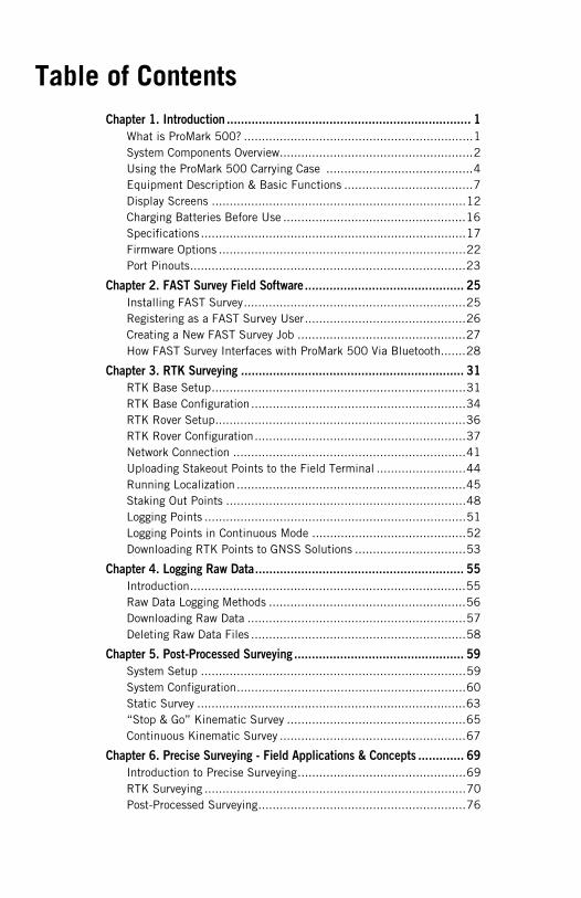
Table of Contents
Chapter 1. Introduction ..................................................................... 1What is ProMark 500? ................................................................1System Components Overview......................................................2Using the ProMark 500 Carrying Case .........................................4Equipment Description & Basic Functions ....................................7Display Screens .......................................................................12Charging Batteries Before Use ...................................................16Specifications ..........................................................................17Firmware Options .....................................................................22Port Pinouts.............................................................................23
Chapter 2. FAST Survey Field Software............................................. 25
Installing FAST Survey..............................................................25Registering as a FAST Survey User.............................................26Creating a New FAST Survey Job ...............................................27How FAST Survey Interfaces with ProMark 500 Via Bluetooth.......28
Chapter 3. RTK Surveying ............................................................... 31
RTK Base Setup.......................................................................31RTK Base Configuration ............................................................34RTK Rover Setup......................................................................36RTK Rover Configuration...........................................................37Network Connection .................................................................41Uploading Stakeout Points to the Field Terminal .........................44Running Localization ................................................................45Staking Out Points ...................................................................48Logging Points .........................................................................51Logging Points in Continuous Mode ...........................................52Downloading RTK Points to GNSS Solutions ...............................53
Chapter 4. Logging Raw Data........................................................... 55
Introduction.............................................................................55Raw Data Logging Methods .......................................................56Downloading Raw Data .............................................................57Deleting Raw Data Files ............................................................58
Chapter 5. Post-Processed Surveying ................................................ 59
System Setup ..........................................................................59System Configuration................................................................60Static Survey ...........................................................................63“Stop & Go” Kinematic Survey ..................................................65Continuous Kinematic Survey ....................................................67
Chapter 6. Precise Surveying - Field Applications & Concepts ............. 69
Introduction to Precise Surveying...............................................69RTK Surveying .........................................................................70Post-Processed Surveying..........................................................76
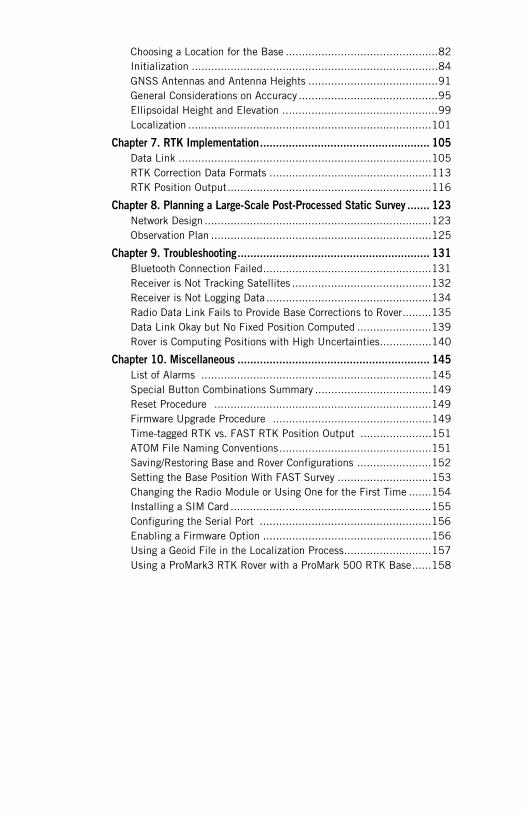
Choosing a Location for the Base ...............................................82Initialization ............................................................................84GNSS Antennas and Antenna Heights ........................................91General Considerations on Accuracy ...........................................95Ellipsoidal Height and Elevation ................................................99Localization ...........................................................................101
Chapter 7. RTK Implementation..................................................... 105
Data Link ..............................................................................105RTK Correction Data Formats ..................................................113RTK Position Output...............................................................116
Chapter 8. Planning a Large-Scale Post-Processed Static Survey ....... 123
Network Design ......................................................................123Observation Plan ....................................................................125
Chapter 9. Troubleshooting............................................................ 131
Bluetooth Connection Failed....................................................131Receiver is Not Tracking Satellites ...........................................132Receiver is Not Logging Data ...................................................134Radio Data Link Fails to Provide Base Corrections to Rover.........135Data Link Okay but No Fixed Position Computed .......................139Rover is Computing Positions with High Uncertainties................140
Chapter 10. Miscellaneous ............................................................ 145
List of Alarms .......................................................................145Special Button Combinations Summary ....................................149Reset Procedure ...................................................................149Firmware Upgrade Procedure .................................................149Time-tagged RTK vs. FAST RTK Position Output ......................151ATOM File Naming Conventions...............................................151Saving/Restoring Base and Rover Configurations .......................152Setting the Base Position With FAST Survey .............................153Changing the Radio Module or Using One for the First Time .......154Installing a SIM Card ..............................................................155Configuring the Serial Port .....................................................156Enabling a Firmware Option ....................................................156Using a Geoid File in the Localization Process...........................157Using a ProMark3 RTK Rover with a ProMark 500 RTK Base......158
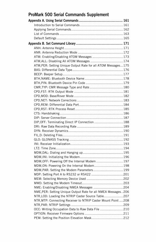
ProMark 500 Serial Commands Supplement
Appendix A. Using Serial Commands .............................................. 161
Introduction to Serial Commands.............................................161Applying Serial Commands......................................................162List of Commands ..................................................................163Default Settings .....................................................................165
Appendix B. Set Command Library ................................................. 171
ANH: Antenna Height .............................................................171ANR: Antenna Reduction Mode ...............................................172ATM: Enabling/Disabling ATOM Messages ................................173ATM,ALL: Disabling All ATOM Messages ..................................174ATM,PER: Setting Unique Output Rate for all ATOM Messages...175BAS: Differential Data Type.....................................................176BEEP: Beeper Setup...............................................................177BTH,NAME: Bluetooth Device Name ........................................178BTH,PIN: Bluetooth Device Pin Code .......................................179CMR,TYP: CMR Message Type and Rate...................................180CPD,FST: RTK Output Mode ...................................................181CPD,MOD: Base/Rover Mode ...................................................182CPD,NET: Network Corrections ................................................183CPD,REM: Differential Data Port..............................................184CPD,RST: RTK Process Reset..................................................185CTS: Handshaking..................................................................186DIP: Server Connection ...........................................................187DIP,OFF: Terminating Direct IP Connection ..............................188DRI: Raw Data Recording Rate ................................................189DYN: Receiver Dynamics.........................................................190FIL,D: Deleting Files...............................................................191GLO: GLONASS Tracking ........................................................192INI: Receiver Initialization.......................................................193LTZ: Time Zone......................................................................194MDM,DAL: Dialing and Hanging up..........................................195MDM,INI: Initializing the Modem.............................................196MDM,OFF: Powering Off the Internal Modem ............................197MDM,ON: Powering On the Internal Modem..............................198MDM,PAR: Setting the Modem Parameters ...............................199MDP: Setting Port A to RS232 or RS422 .................................201MEM: Selecting Memory Device Used ......................................202MWD: Setting the Modem Timeout...........................................203NME: Enabling/Disabling NMEA Messages ...............................204NME,PER: Setting Unique Output Rate for all NMEA Messages..206NTR,LOD: Loading the NTRIP Caster Source Table....................207NTR,MTP: Connecting Receiver to NTRIP Caster Mount Point ....208NTR,PAR: NTRIP Settings ......................................................209OCC: Writing Occupation Data to Raw Data File ........................210OPTION: Receiver Firmware Options ........................................211PEM: Setting the Position Elevation Mask.................................212
POS: Setting the Antenna Position ...........................................213PRT: Setting Baud Rates.........................................................214PWR,OFF: Powering Off the Receiver .......................................215PWR,PAR: Power Management ................................................216RAW: Enabling/Disabling Raw Data Messages in Ashtech Format 217RAW,PER: Setting Unique Output Rate for Raw Data.................219RDP,OFF: Powering Off the Internal Radio................................220RDP,ON: Powering On the Internal Radio .................................221RDP,PAR: Setting the Radio....................................................222RDP,TYP: Defining the Type of Radio Used...............................224REC: Enable/Disable, Start/Stop Raw Data Recording ................225RST: Default Settings .............................................................226RTC,MSG: Defining a User Message.........................................227RTC,TYP: RTCM Message Type ................................................228SBA: Enabling/Disabling SBAS Tracking...................................230SBA: Enabling/Disabling SBAS Messages .................................231SBA,ALL: Disabling All SBAS Messages ...................................232SIT: Defining a Site Name.......................................................233STI: Defining a Station ID .......................................................234WAK: Acknowledging Alarms ...................................................235ZDA: Setting Time & Date .......................................................236
Appendix C. Query Command Library .............................................. 237
ALM: Almanac Message ..........................................................237ANH: Antenna Height .............................................................239ANR: Antenna Reduction Mode ...............................................240ATM: ATOM Data Parameters ..................................................241ATO: ATOM Message Parameters .............................................243BAS: Differential Data Type.....................................................244BEEP: Beeper State................................................................245BTH: Bluetooth Settings .........................................................246CMR,MSI: CMR Message Status ..............................................247CPD,AFP: Ambiguity Fixing Parameter......................................248CPD,ANT: Base Antenna Height...............................................249CPD,FST: Fast RTK Output Mode.............................................250CPD,MOD: Base/Rover Mode ...................................................251CPD,NET: RTK Network Operation Mode ..................................252CPD,POS: Base Position .........................................................253CPD,REM: Differential Data Port..............................................254CRT: Cartesian Coordinates of Position .....................................255CTS: Handshaking..................................................................256DCR: Cartesian Coordinates of Baseline ....................................257DIP: Direct IP Parameters .......................................................258DPO: Delta Position ................................................................259DRI: Raw Data Recording Rate ................................................260DYN: Receiver Dynamics.........................................................261ELM: Elevation Mask ..............................................................262
FLS: List of Raw Data Files .....................................................263GGA: GNSS Position Message..................................................264GLL: Geographic Position - Latitude/Longitude..........................265GLO: GLONASS Tracking Status ..............................................266GRS: GNSS Range Residuals ..................................................267GSA: GNSS DOP and Active Satellites......................................268GST: GNSS Pseudo-Range Error Statistics ................................269GSV: GNSS Satellites in View ..................................................270MDM,LVL: Modem Signal Level ...............................................271MDM: Modem Status and Parameters.......................................272MDP: Port A Setting ...............................................................274MEM: Selected Memory Device................................................275MWD: Modem Watchdog Timeout ............................................276NMO: NMEA Message Output Settings .....................................277NTR: NTRIP Settings..............................................................279NTR,TBL: Source Table ..........................................................279OCC: Ocupation State and Parameters......................................281OPTION: Installed Receiver Firmware Options...........................282PEM: Position Elevation Mask .................................................283POS: Computed Position Data .................................................284PRT: Baud Rate Settings ........................................................285PWR,PAR: Power Status .........................................................286RAW: Raw Data Logging Settings.............................................287RDP,CHT: Radio Channel Table...............................................288RDP,PAR: Radio Parameters ...................................................289RDP,TYP: Radio Type Used.....................................................291REC: Raw Data Recording Status.............................................292RID: Receiver Identification ....................................................293RMC: Recommended Minimum Specific GNSS Data .................294RRE: Residual Error ...............................................................295RTC: RTCM Status .................................................................296RTC,MSI: RTCM Message Status .............................................298RWO: Raw Data Output Settings ..............................................299SAT: Satellites Status .............................................................301SBA: SBAS Tracking Status ....................................................302SBA,INF: SBAS Info Message Output.......................................303SBO: SBAS Message Output Settings.......................................304SIT: Site Name ......................................................................305STI: Station ID.......................................................................306VEC: Vector & Accuracy Data...................................................307VERSION: Firmware Version ....................................................308VTG: Course Over Ground and Ground Speed ............................309WARN: Warning Messages.......................................................310ZDA: Time & Date ..................................................................312
Bluetooth Manager Module125


Chapter 1. Introduction
What is ProMark 500?
Congratulations! You have just acquired the latest dual-frequency ProMark 500 GNSS Surveying System from Magellan!GNSS has revolutionized control surveys, topographic data collection and construction surveying. Purchasing the right tools for a professional job is essential in today's competitive business environment. Learning to put these tools to work quickly and efficiently will be the focus of the present manual.Compared to its predecessors, ProMark 500 is more compact and lightweight while integrating more technology, such as the exclusive Magellan BLADE™ algorithms and multi-constellation (GPS+GLONASS+SBAS) capabilities.In addition, because it’s easy to use, you will be able to focus on your job and forget almost everything about the technical aspects of your equipment. No more cables, no more clip-on modules: ProMark 500 will be the reliable tool you are expecting for all your GNSS survey operations!
1
Introduction
System Components Overview
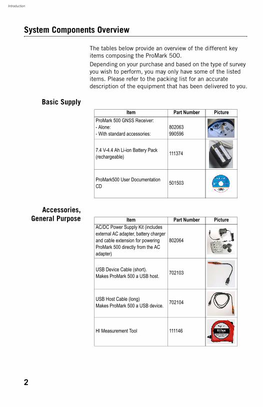
The tables below provide an overview of the different key items composing the ProMark 500. Depending on your purchase and based on the type of survey you wish to perform, you may only have some of the listed items. Please refer to the packing list for an accurate description of the equipment that has been delivered to you.
Basic Supply
Accessories,General Purpose
Item Part Number PictureProMark 500 GNSS Receiver:- Alone:- With standard accessories:
802063990596
7.4 V-4.4 Ah Li-ion Battery Pack (rechargeable) 111374
ProMark500 User Documentation CD 501503
Item Part Number PictureAC/DC Power Supply Kit (includes external AC adapter, battery charger and cable extension for powering ProMark 500 directly from the AC adapter)
802064
USB Device Cable (short).Makes ProMark 500 a USB host. 702103
USB Host Cable (long)Makes ProMark 500 a USB device. 702104
HI Measurement Tool 111146
2
Introduction
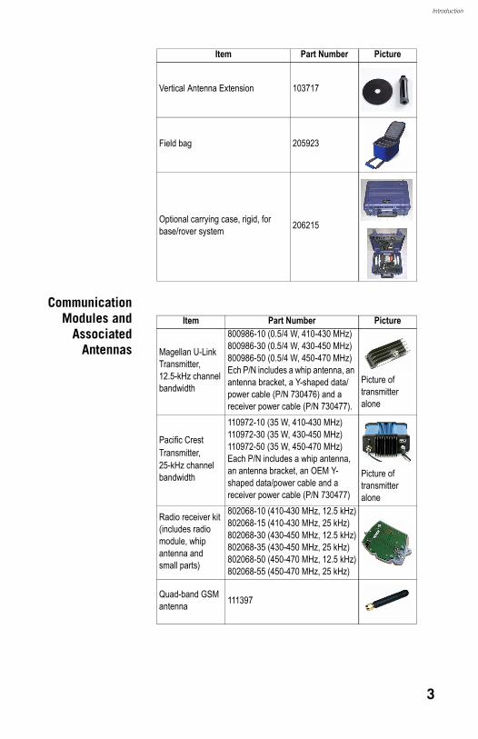
CommunicationModules and
AssociatedAntennas
Vertical Antenna Extension 103717
Field bag 205923
Optional carrying case, rigid, for base/rover system 206215
Item Part Number Picture
Item Part Number Picture
Magellan U-Link Transmitter,12.5-kHz channel bandwidth
800986-10 (0.5/4 W, 410-430 MHz)800986-30 (0.5/4 W, 430-450 MHz)800986-50 (0.5/4 W, 450-470 MHz)Ech P/N includes a whip antenna, an antenna bracket, a Y-shaped data/power cable (P/N 730476) and a receiver power cable (P/N 730477).
Picture of transmitter alone
Pacific Crest Transmitter,25-kHz channel bandwidth
110972-10 (35 W, 410-430 MHz)110972-30 (35 W, 430-450 MHz)110972-50 (35 W, 450-470 MHz)Each P/N includes a whip antenna, an antenna bracket, an OEM Y-shaped data/power cable and a receiver power cable (P/N 730477)
Picture of transmitter alone
Radio receiver kit (includes radio module, whip antenna and small parts)
802068-10 (410-430 MHz, 12.5 kHz)802068-15 (410-430 MHz, 25 kHz)802068-30 (430-450 MHz, 12.5 kHz)802068-35 (430-450 MHz, 25 kHz)802068-50 (450-470 MHz, 12.5 kHz)802068-55 (450-470 MHz, 25 kHz)
Quad-band GSM antenna 111397
3

Introduction
Base Accessories
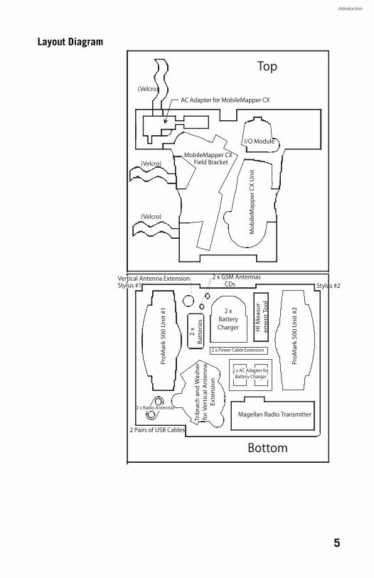
Using the ProMark 500 Carrying Case
This section explains how to arrange the different pieces of equipment in the ProMark 500 carrying case.
Item Part Number PictureExternal DC Power Cable for Receiver
730477
Magellan Trans-mitter Data/Power Cable
730476
4
Introduction
Layout Diagram
AC Adapter for MobileMapper CX
Mo
bile
Map
per
CX
Un
it
I/O Module
Field BracketMobileMapper CX
2 x GSM Antennas
2 x
Bat
teri
es
Stylus #2P
roM
ark
50
0 U
nit
#2
Magellan Radio Transmitter
Pro
Mar
k 5
00
Un
it #
1
CDs
Trib
rach
an
d W
ash
erfo
r V
erti
cal A
nte
nn
aEx
ten
sio
n
2 xBatteryCharger H
I Mea
sur-
emen
t To
ol
2 x Power Cable Extension
2 Pairs of USB Cables
Top
Bottom
(Velcro)
(Velcro)
(Velcro)
2 x AC Adapter forBattery Charger
2 x Radio Antennas
Vertical Antenna ExtensionStylus #1
5
Introduction
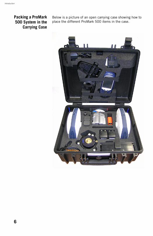
Packing a ProMark500 System in the
Carrying Case
Below is a picture of an open carrying case showing how to place the different ProMark 500 items in the case.
6
Introduction
Equipment Description & Basic Functions
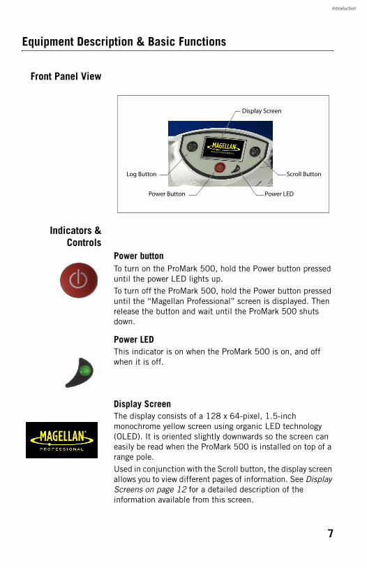
Front Panel View
Indicators &Controls
Power buttonTo turn on the ProMark 500, hold the Power button pressed until the power LED lights up.To turn off the ProMark 500, hold the Power button pressed until the “Magellan Professional” screen is displayed. Then release the button and wait until the ProMark 500 shuts down.
Power LEDThis indicator is on when the ProMark 500 is on, and off when it is off.
Display ScreenThe display consists of a 128 x 64-pixel, 1.5-inch monochrome yellow screen using organic LED technology (OLED). It is oriented slightly downwards so the screen can easily be read when the ProMark 500 is installed on top of a range pole. Used in conjunction with the Scroll button, the display screen allows you to view different pages of information. See Display Screens on page 12 for a detailed description of the information available from this screen.
Power Button
Log Button Scroll Button
Power LED
Display Screen
7
Introduction
After a few seconds of inactivity (i.e. Scroll button idle), screen luminosity turns from high to low level.
Scroll buttonPress this button shortly to scroll through the different pages of information viewed on the screen.If an alarm is reported on the display screen, a short press on the Scroll button will acknowledge the alarm. The Scroll button will recover its display scrolling function only after all the alarms have been acknowledged this way.Another function of the Scroll button is to re-activate the screen backlight after the latter has automatically been turned off. The Scroll button is also used in the firmware update procedure.
Log ButtonPress this button briefly to start recording raw data on the selected storage medium.Another short press on this button will immediately stop raw data recording.
BuzzerThe internal buzzer will sound an alarm whenever a warning message is reported on the screen. The buzzer will beep until you acknowledge the warning message by pressing the Scroll button. The buzzer can be deactivated permanently using the $PASHS,BEEP command. See BEEP: Beeper Setup on page 177.
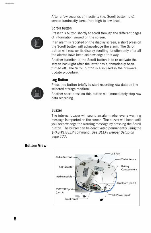
Bottom View
5/8” adaptor BatteryCompartment
GSM AntennaRadio Antenna
DC Power Input
RS232/422 port(port A)
Radio module
Bluetooth (port C)
Front Panel
USB Port
8
Introduction
Battery,Connectors &
Module
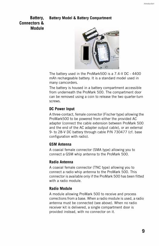
Battery Model & Battery Compartment
The battery used in the ProMark500 is a 7.4-V DC - 4400 mAh rechargeable battery. It is a standard model used in many camcorders.The battery is housed in a battery compartment accessible from underneath the ProMark 500. The compartment door can be removed using a coin to release the two quarter-turn screws.
DC Power InputA three-contact, female connector (Fischer type) allowing the ProMark500 to be powered from either the provided AC adapter (connect the cable extension between ProMark 500 and the end of the AC adapter output cable), or an external 9- to 28-V DC battery through cable P/N 730477 (cf. base configuration with radio).
GSM AntennaA coaxial female connector (SMA type) allowing you to connect a GSM whip antenna to the ProMark 500.
Radio AntennaA coaxial female connector (TNC type) allowing you to connect a radio whip antenna to the ProMark 500. This connector is available only if the ProMark 500 has been fitted with a radio module.
Radio ModuleA module allowing ProMark 500 to receive and process corrections from a base. When a radio module is used, a radio antenna must be connected (see above). When no radio receiver kit is delivered, a single compartment door is provided instead, with no connector on it.
9
Introduction
USB PortA nine-contact female connector (Fischer type). Depending on how it is configured, the USB port can be used in two different ways:1. For a USB host such as a mass storage device. In this
case, you should use the special adaptor cable provided (P/N 702103) to attach the USB key to the ProMark 500. This configuration can be used to log raw data on the USB key or upgrade the ProMark 500 firmware from the files stored on the key.
2. For a USB device allowing ProMark 500 to be seen as a disk from the computer connected to this port. In this configuration, files can be transferred between the ProMark500’s internal memory and the computer using the USB cable provided (P/N 702104).
RS232/422 Serial PortA seven-contact female connector (Fischer type) allowing you to connect the ProMark 500 to an external device via an RS232 or RS422 serial line (default: RS232). Changing the configuration of the port can be done from the field terminal using the $PASHS,MDP serial command. See MDP: Setting Port A to RS232 or RS422 on page 201.
Bluetooth DeviceAn integrated Bluetooth module allowing the ProMark 500 to communicate with a Bluetooth-enabled field terminal through a wireless connection.
10
Introduction
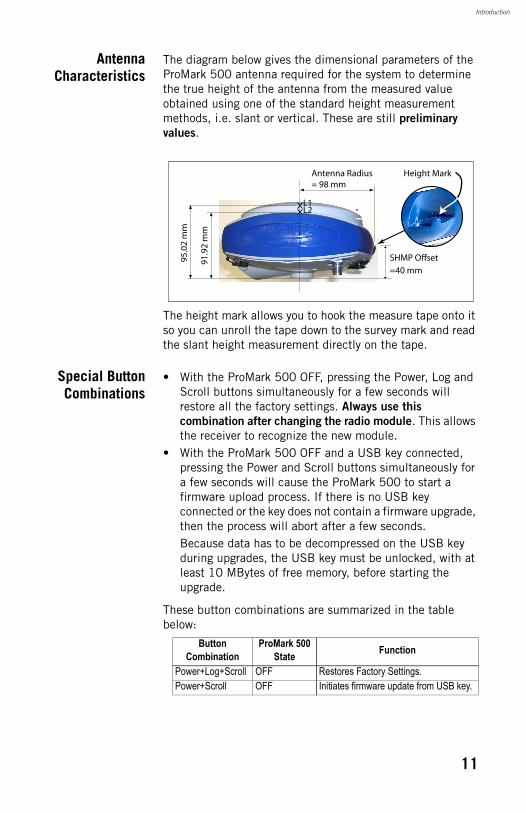
AntennaCharacteristics
The diagram below gives the dimensional parameters of the ProMark 500 antenna required for the system to determine the true height of the antenna from the measured value obtained using one of the standard height measurement methods, i.e. slant or vertical. These are still preliminary values.
The height mark allows you to hook the measure tape onto it so you can unroll the tape down to the survey mark and read the slant height measurement directly on the tape.
Special ButtonCombinations
• With the ProMark 500 OFF, pressing the Power, Log and Scroll buttons simultaneously for a few seconds will restore all the factory settings. Always use this
combination after changing the radio module. This allows the receiver to recognize the new module.
• With the ProMark 500 OFF and a USB key connected, pressing the Power and Scroll buttons simultaneously for a few seconds will cause the ProMark 500 to start a firmware upload process. If there is no USB key connected or the key does not contain a firmware upgrade, then the process will abort after a few seconds.Because data has to be decompressed on the USB key during upgrades, the USB key must be unlocked, with at least 10 MBytes of free memory, before starting the upgrade.
These button combinations are summarized in the table below:
91.9
2 m
m
95.0
2 m
m
L1L2
Antenna Radius= 98 mm
Height Mark
SHMP Offset
=40 mm
Button Combination
ProMark 500 State Function
Power+Log+Scroll OFF Restores Factory Settings.Power+Scroll OFF Initiates firmware update from USB key.
11
Introduction
Display Screens
If you press the Scroll button several times, you will see the following displays successively.
Power-On Screen When you power on the ProMark 500, the Magellan Professional logo appears on the screen. It is displayed until the ProMark 500 has completed its auto-test (this takes about 30 seconds).
Then the General Status screen is displayed.
General StatusScreen
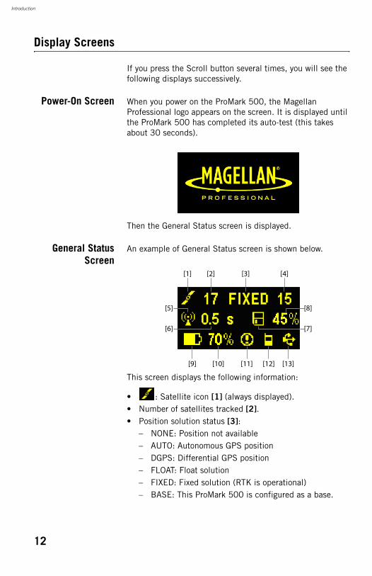
An example of General Status screen is shown below.
This screen displays the following information:
• : Satellite icon [1] (always displayed).• Number of satellites tracked [2].• Position solution status [3]:
– NONE: Position not available– AUTO: Autonomous GPS position– DGPS: Differential GPS position– FLOAT: Float solution– FIXED: Fixed solution (RTK is operational)– BASE: This ProMark 500 is configured as a base.
[1]
[9] [10] [11] [12] [13]
[2] [3] [4]
[5]
[6]
[8]
[7]
12
Introduction
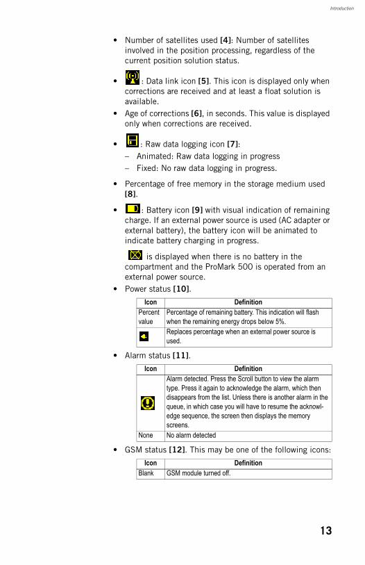
• Number of satellites used [4]: Number of satellites involved in the position processing, regardless of the current position solution status.
• : Data link icon [5]. This icon is displayed only when corrections are received and at least a float solution is available.
• Age of corrections [6], in seconds. This value is displayed only when corrections are received.
• : Raw data logging icon [7]:– Animated: Raw data logging in progress– Fixed: No raw data logging in progress.
• Percentage of free memory in the storage medium used [8].
• : Battery icon [9] with visual indication of remaining charge. If an external power source is used (AC adapter or external battery), the battery icon will be animated to indicate battery charging in progress.
is displayed when there is no battery in the compartment and the ProMark 500 is operated from an external power source.
• Power status [10].
• Alarm status [11].
• GSM status [12]. This may be one of the following icons:
Icon DefinitionPercent value
Percentage of remaining battery. This indication will flash when the remaining energy drops below 5%.Replaces percentage when an external power source is used.
Icon DefinitionAlarm detected. Press the Scroll button to view the alarm type. Press it again to acknowledge the alarm, which then disappears from the list. Unless there is another alarm in the queue, in which case you will have to resume the acknowl-edge sequence, the screen then displays the memory screens.
None No alarm detected
Icon DefinitionBlank GSM module turned off.
13
Introduction
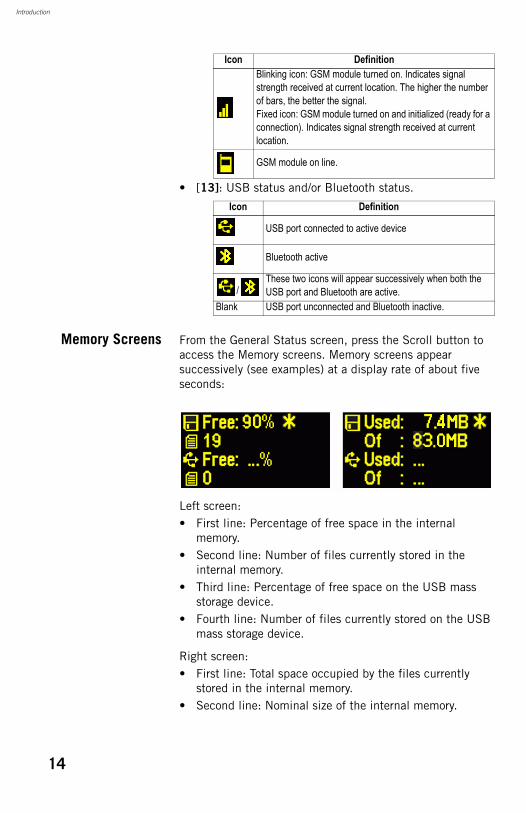
• [13]: USB status and/or Bluetooth status.
Memory Screens From the General Status screen, press the Scroll button to access the Memory screens. Memory screens appear successively (see examples) at a display rate of about five seconds:
Left screen:• First line: Percentage of free space in the internal
memory.• Second line: Number of files currently stored in the
internal memory.• Third line: Percentage of free space on the USB mass
storage device.• Fourth line: Number of files currently stored on the USB
mass storage device.
Right screen:• First line: Total space occupied by the files currently
stored in the internal memory.• Second line: Nominal size of the internal memory.
Blinking icon: GSM module turned on. Indicates signal strength received at current location. The higher the number of bars, the better the signal.Fixed icon: GSM module turned on and initialized (ready for a connection). Indicates signal strength received at current location.
GSM module on line.
Icon Definition
USB port connected to active device
Bluetooth active
/These two icons will appear successively when both the USB port and Bluetooth are active.
Blank USB port unconnected and Bluetooth inactive.
Icon Definition
14
Introduction
• Third line: Total space occupied by the files currently stored on the USB mass storage device.
• Fourth line: Nominal size of the USB mass storage device.
About the “*” symbol:• It can only appear at the end of the first or third line.• Where placed, it indicates that this storage medium is
used for data logging.
What if there is no USB mass storage device connected to ProMark 500?• Parameters relevant to the USB key size and space used
and available are void (three dots displayed instead).• Number of files is forced to “0”.
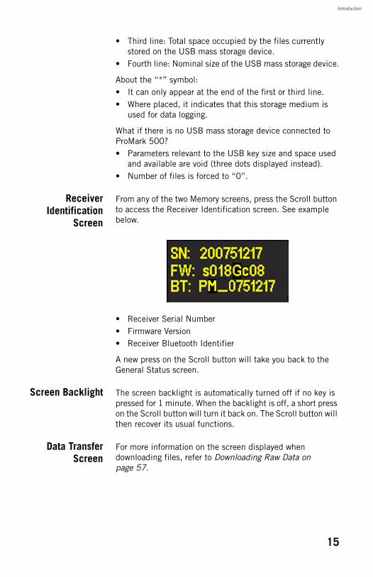
ReceiverIdentification
Screen
From any of the two Memory screens, press the Scroll button to access the Receiver Identification screen. See example below.
• Receiver Serial Number• Firmware Version• Receiver Bluetooth Identifier
A new press on the Scroll button will take you back to the General Status screen.
Screen Backlight The screen backlight is automatically turned off if no key is pressed for 1 minute. When the backlight is off, a short press on the Scroll button will turn it back on. The Scroll button will then recover its usual functions.
Data TransferScreen
For more information on the screen displayed when downloading files, refer to Downloading Raw Data on page 57.
15

Introduction
Charging Batteries Before Use
Make sure the battery is fully charged for each ProMark 500 you will be using in the field. Follow the instructions below to charge a battery.
Removing theBattery from the
ProMark 500
Unless the battery has already been taken out, do the following:• Put the ProMark 500 upside down.• Remove the battery door, accessible from underneath the
ProMark 500, by loosening the two quarter-turn screws (see picture) using a coin.
• Keeping one hand on the battery still in its compartment, put the ProMark 500 the right way up. The battery will then easily slide out of the battery compartment.
Charging theBattery
The battery charger comes with a separate universal AC adapter fitted with a 1.5-m output cable. The AC adapter includes a choice of four different, detachable plug types. Follow the instructions below to operate the charger.• Choose the plug type that is suitable for your country.• Secure that plug on the AC adapter by giving the plug the
right orientation with respect to the adapter, then pushing and rotating it by about 10 degrees clockwise until you hear a “click”.
• Connect the cable from the AC adapter to the battery charger.
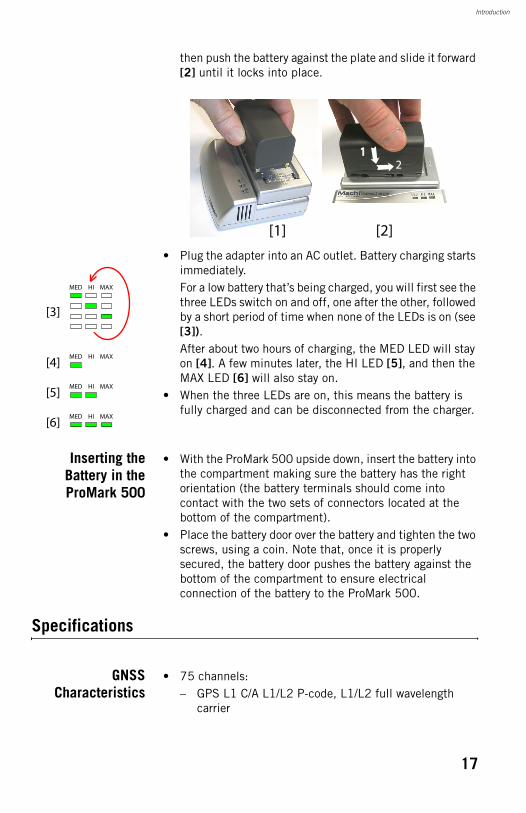
• Give the battery the right orientation with respect to the charger [1] (the battery terminals should come into contact with the two sets of connectors on the charger),
16
Introduction
then push the battery against the plate and slide it forward [2] until it locks into place.
• Plug the adapter into an AC outlet. Battery charging starts immediately.For a low battery that’s being charged, you will first see the three LEDs switch on and off, one after the other, followed by a short period of time when none of the LEDs is on (see [3]).After about two hours of charging, the MED LED will stay on [4]. A few minutes later, the HI LED [5], and then the MAX LED [6] will also stay on.
• When the three LEDs are on, this means the battery is fully charged and can be disconnected from the charger.
Inserting theBattery in theProMark 500
• With the ProMark 500 upside down, insert the battery into the compartment making sure the battery has the right orientation (the battery terminals should come into contact with the two sets of connectors located at the bottom of the compartment).
• Place the battery door over the battery and tighten the two screws, using a coin. Note that, once it is properly secured, the battery door pushes the battery against the bottom of the compartment to ensure electrical connection of the battery to the ProMark 500.
Specifications
GNSSCharacteristics
• 75 channels:– GPS L1 C/A L1/L2 P-code, L1/L2 full wavelength
carrier
[1] [2]
112
MED MAXHI
MED MAXHI
[3]
[6]
MED MAXHI[5]
MED MAXHI[4]
17
Introduction
– GLONASS L1 C/A L1/L2 P-code, L1/L2 full wavelength carrier
– SBAS code & carrier (WAAS/EGNOS/MSAS)– Low-signal acquisition and tracking engines for signal
detection in difficult environments
• Fully independent code and phase measurements• Magellan BLADE™ technology for optimal performance• Advanced multipath mitigation• Update rate: 10 Hz
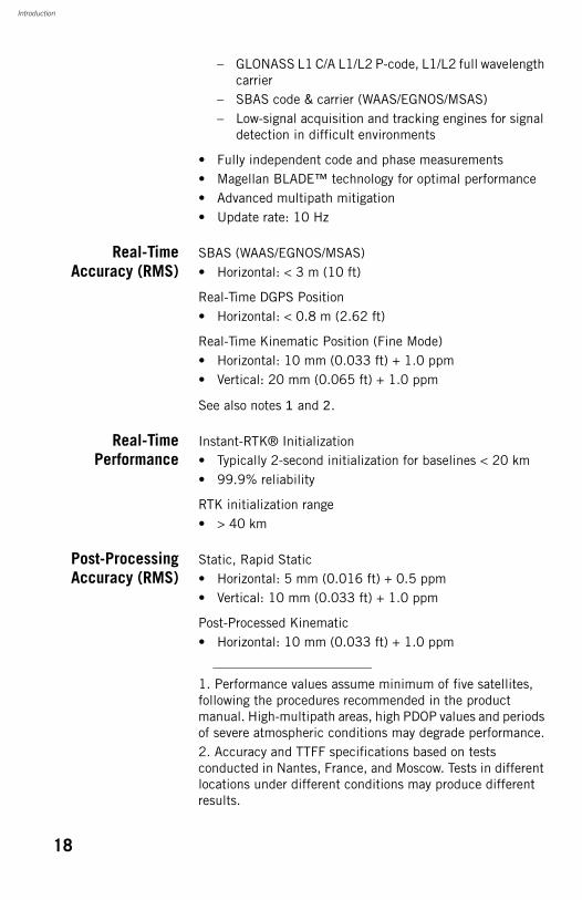
Real-TimeAccuracy (RMS)
SBAS (WAAS/EGNOS/MSAS)• Horizontal: < 3 m (10 ft)
Real-Time DGPS Position• Horizontal: < 0.8 m (2.62 ft)
Real-Time Kinematic Position (Fine Mode)• Horizontal: 10 mm (0.033 ft) + 1.0 ppm• Vertical: 20 mm (0.065 ft) + 1.0 ppm
See also notes 1 and 2.
Real-TimePerformance
Instant-RTK® Initialization• Typically 2-second initialization for baselines < 20 km• 99.9% reliability
RTK initialization range• > 40 km
Post-ProcessingAccuracy (RMS)
Static, Rapid Static• Horizontal: 5 mm (0.016 ft) + 0.5 ppm• Vertical: 10 mm (0.033 ft) + 1.0 ppm
Post-Processed Kinematic• Horizontal: 10 mm (0.033 ft) + 1.0 ppm
1. Performance values assume minimum of five satellites, following the procedures recommended in the product manual. High-multipath areas, high PDOP values and periods of severe atmospheric conditions may degrade performance.2. Accuracy and TTFF specifications based on tests conducted in Nantes, France, and Moscow. Tests in different locations under different conditions may produce different results.
18
Introduction
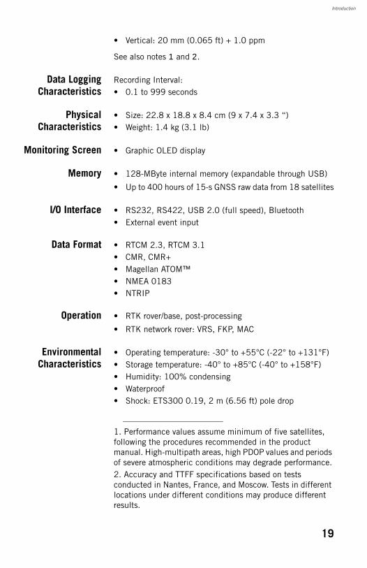
• Vertical: 20 mm (0.065 ft) + 1.0 ppm
See also notes 1 and 2.
Data LoggingCharacteristics
Recording Interval:• 0.1 to 999 seconds
PhysicalCharacteristics
• Size: 22.8 x 18.8 x 8.4 cm (9 x 7.4 x 3.3 “)• Weight: 1.4 kg (3.1 lb)
Monitoring Screen • Graphic OLED display
Memory • 128-MByte internal memory (expandable through USB)
• Up to 400 hours of 15-s GNSS raw data from 18 satellites
I/O Interface • RS232, RS422, USB 2.0 (full speed), Bluetooth• External event input
Data Format • RTCM 2.3, RTCM 3.1• CMR, CMR+• Magellan ATOM™• NMEA 0183• NTRIP
Operation • RTK rover/base, post-processing
• RTK network rover: VRS, FKP, MAC
EnvironmentalCharacteristics
• Operating temperature: -30° to +55°C (-22° to +131°F)• Storage temperature: -40° to +85°C (-40° to +158°F)• Humidity: 100% condensing• Waterproof• Shock: ETS300 0.19, 2 m (6.56 ft) pole drop
1. Performance values assume minimum of five satellites, following the procedures recommended in the product manual. High-multipath areas, high PDOP values and periods of severe atmospheric conditions may degrade performance.2. Accuracy and TTFF specifications based on tests conducted in Nantes, France, and Moscow. Tests in different locations under different conditions may produce different results.
19
Introduction
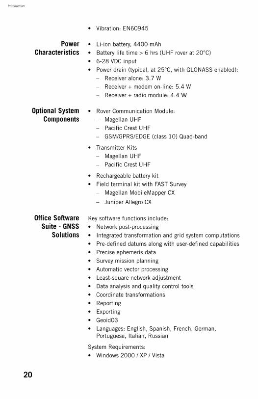
• Vibration: EN60945
PowerCharacteristics
• Li-ion battery, 4400 mAh• Battery life time > 6 hrs (UHF rover at 20°C)• 6-28 VDC input• Power drain (typical, at 25°C, with GLONASS enabled):
– Receiver alone: 3.7 W– Receiver + modem on-line: 5.4 W– Receiver + radio module: 4.4 W
Optional SystemComponents
• Rover Communication Module:– Magellan UHF– Pacific Crest UHF– GSM/GPRS/EDGE (class 10) Quad-band
• Transmitter Kits– Magellan UHF– Pacific Crest UHF
• Rechargeable battery kit• Field terminal kit with FAST Survey
– Magellan MobileMapper CX
– Juniper Allegro CX
Office SoftwareSuite - GNSS
Solutions
Key software functions include:• Network post-processing• Integrated transformation and grid system computations• Pre-defined datums along with user-defined capabilities• Precise ephemeris data• Survey mission planning• Automatic vector processing• Least-square network adjustment• Data analysis and quality control tools• Coordinate transformations• Reporting• Exporting• Geoid03• Languages: English, Spanish, French, German,
Portuguese, Italian, Russian
System Requirements:• Windows 2000 / XP / Vista
20

Introduction
• Pentium® 133 or higher• 32-MB RAM• 90-MB disk space required for installation
Field SoftwareSuite - FAST
Survey
Key software functions include:• ProMark 500 GNSS support: configuration, monitoring
and control• Volume computation• Background raster image• Network connectivity• Coordinate system support: predefined grid systems,
predefined datums, projections, geoids, local grid• Map view with colored lines• Geodetic geometry: intersection, azimuth/distance,
offsetting, polyline, curve, area• Data import/export: DXF, SHP, RW5, LandXML, etc.• Survey utilities: calculator, RW5 file viewing• Optical Surveying Instruments (optional)• Road construction (optional)• Robotic total stations (optional)
Supported hardware 1:– Magellan MobileMapper CX– Juniper Allegro CX
1. Other field software & controllers are also compatible with ProMark 500.
21
Introduction
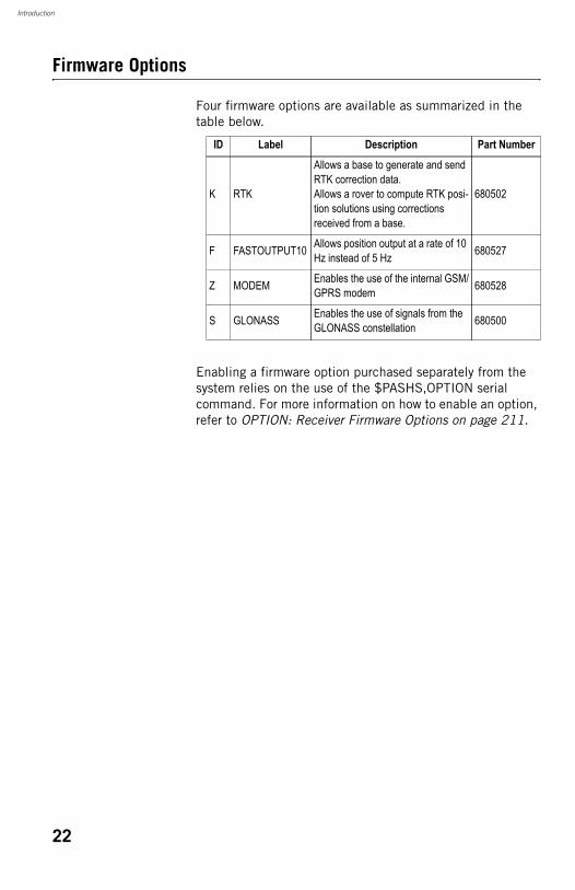
Firmware Options
Four firmware options are available as summarized in the table below.
Enabling a firmware option purchased separately from the system relies on the use of the $PASHS,OPTION serial command. For more information on how to enable an option, refer to OPTION: Receiver Firmware Options on page 211.
ID Label Description Part Number
K RTK
Allows a base to generate and send RTK correction data.Allows a rover to compute RTK posi-tion solutions using corrections received from a base.
680502
F FASTOUTPUT10 Allows position output at a rate of 10 Hz instead of 5 Hz 680527
Z MODEM Enables the use of the internal GSM/GPRS modem 680528
S GLONASS Enables the use of signals from the GLONASS constellation 680500
22
Introduction
Port Pinouts
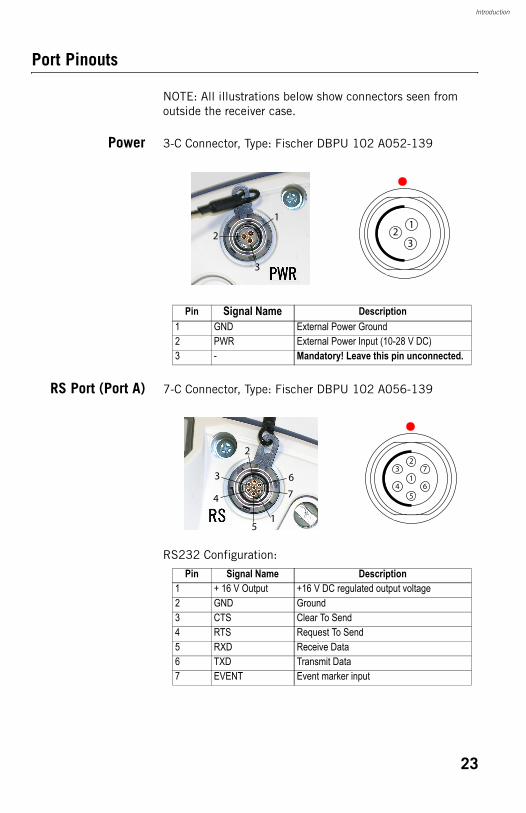
NOTE: All illustrations below show connectors seen from outside the receiver case.
Power 3-C Connector, Type: Fischer DBPU 102 A052-139
RS Port (Port A) 7-C Connector, Type: Fischer DBPU 102 A056-139
RS232 Configuration:
Pin Signal Name Description1 GND External Power Ground2 PWR External Power Input (10-28 V DC)3 - Mandatory! Leave this pin unconnected.
11
223
3
Pin Signal Name Description1 + 16 V Output +16 V DC regulated output voltage2 GND Ground3 CTS Clear To Send4 RTS Request To Send5 RXD Receive Data6 TXD Transmit Data7 EVENT Event marker input
1
23
4
7
65
5
4
6
7
2
1
3
23
Introduction
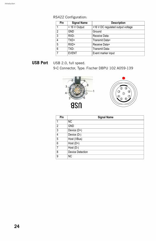
RS422 Configuration:
USB Port USB 2.0, full speed.9-C Connector, Type: Fischer DBPU 102 A059-139
Pin Signal Name Description1 + 16 V Output +16 V DC regulated output voltage2 GND Ground3 RXD- Receive Data-4 TXD+ Transmit Data+5 RXD+ Receive Data+6 TXD- Transmit Data-7 EVENT Event marker input
Pin Signal Name1 NC2 GND3 Device (D+)4 Device (D-)5 Host (VBus)6 Host (D+)7 Host (D-)8 Device Detection9 NC
1
2
3
4 7
8
9
655
4
6
98
7
2
1
3
24
Chapter 2. FAST Survey Field Software
Installing FAST Survey
This section describes how to install FAST Survey from the CD provided, using an office computer. The FAST Survey software can also be downloaded from the Magellan FTP server.If Windows XP (or older OS version) is used on your computer, you first need to install Microsoft Active Sync on your office computer. If Vista is used, you don’t normally need to install an additional program on your computer. However, if the installation of FAST Survey fails, you will have first to install Windows Mobile Device Center and then resume the installation of FAST Survey.The latest versions of ActiveSync and Device Center can be downloaded from http://www.microsoft.com/windowsmobile/activesync/default.mspx at no cost. ActiveSync 4.5 can be installed directly from your FAST Survey CD.
InstallationProcedure
• Connect the field terminal to your office computer using the USB data cable provided.
• Turn on the field terminal.• Insert the FAST Survey CD in your office computer. This
automatically starts the setup file stored on the CD.• Click on the Install FAST Survey for ProMark500 and Z-Max
option then on the Install FAST Survey 2.3 for MobileMapper CX option. This starts the FAST Survey Setup Wizard.
• Click Next>.• Check on the I accept the terms in the License Agreement
option and then click Install.• Confirm installation in the default folder by clicking Yes.
The wizard starts copying the installation files to the field terminal. At the end of this phase, a message window appears asking you to check the field terminal screen to
25

FAST Survey Field Software
see if additional steps are needed to complete the installation.
• Click OK, then Finish to complete installation on computer side.
• On the field terminal the installation phase has automatically started. When the progress bar disappears from the screen, this means installation is complete. The FAST Survey icon can then be seen on the screen.
Registering as a FAST Survey User
The first time you start FAST Survey, you will be prompted to register your license of the software. If you do not register, FAST Survey will remain in demo mode, limiting each job file to a maximum of 30 points.
How to Register FAST Survey registration is done via the Internet at the following address: Magellan FAST Survey Registration Choose Yes to start the registration process. You will be required to enter the following information:• User Name• Company Name• Serial Number*• Email Address• Phone Number• Fax Number• Hardware ID#1*• Hardware ID#2*• Reason for Install• Registration Code*
*: Select Equip>About Magellan Fast Survey>Change Registration in FAST Survey to read this information.After you submit this information, your change key will be displayed and emailed to the address that you submit. Keep this for your permanent records. You may then enter the manufacturer and model of your equipment.If you do not have access to the Internet, you may fax the above information to (+1) 606-564-9525. Your registration information will be faxed back to you within 48 hours. During this time, you may continue to use the program without restriction. After you receive your Change Key, enter it and tap
26
FAST Survey Field Software
OK. You can then create a new FAST Survey job, as explained further.
Saving yourregistration in the
Field Terminal
When you register FAST Survey in a Magellan MobileMapper CX, the code is automatically and safely saved at the end of the registration procedure.With a Juniper Allegro CX, you need to perform a RAM backup or a System Save to be sure your authorization code will not be lost when you next reboot your Allegro CX. If you cannot find this option on the Allegro CX Start menu, then open the Control Panel and choose RAM backup.
Creating a New FAST Survey Job
1. Turn on the field terminal and wait until the boot sequence is complete.
2. Make sure the clock is set properly before starting FAST Survey.
3. Double-tap to launch FAST Survey.4. Tap the Select New/Existing Job button. This opens the
Coordinate Files window.5. Tap on the highlighted “crd” file name located at the
bottom of the screen. This opens FAST Survey’s virtual keyboard with the file name now appearing above.
6. Using the keyboard, type in the name of the “crd” file in which FAST Survey will store the data you will collect during your job.
7. Tap . This takes you back to the Coordinate Files window where your file name now appears in the Name field.
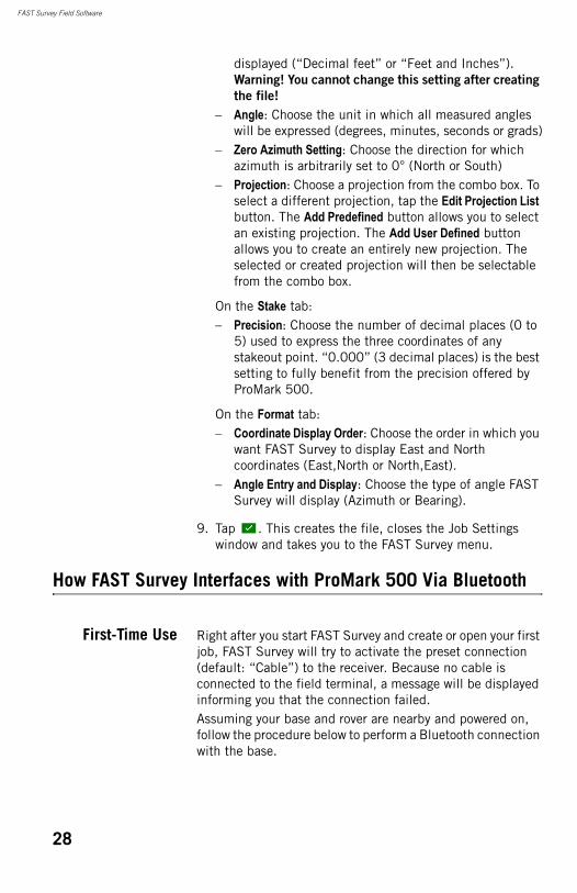
8. Tap again. This opens the Job Settings window, which consists of five different tabs on which you can set a large number of parameters pertaining to the job (or future jobs).Only the parameters that make sense with a GNSS system such as the ProMark 500 are presented below. All other parameters should be kept with their default settings. On the System tab:– Distance: Choose the unit in which all measured
distances will be expressed (US Survey Feet, Metric or International Feet). Unless “Metric” is selected, you can also choose the units in which distances will be
27
FAST Survey Field Software
displayed (“Decimal feet” or “Feet and Inches”). Warning! You cannot change this setting after creating
the file!
– Angle: Choose the unit in which all measured angles will be expressed (degrees, minutes, seconds or grads)
– Zero Azimuth Setting: Choose the direction for which azimuth is arbitrarily set to 0° (North or South)
– Projection: Choose a projection from the combo box. To select a different projection, tap the Edit Projection List button. The Add Predefined button allows you to select an existing projection. The Add User Defined button allows you to create an entirely new projection. The selected or created projection will then be selectable from the combo box.
On the Stake tab:– Precision: Choose the number of decimal places (0 to
5) used to express the three coordinates of any stakeout point. “0.000” (3 decimal places) is the best setting to fully benefit from the precision offered by ProMark 500.
On the Format tab:– Coordinate Display Order: Choose the order in which you
want FAST Survey to display East and North coordinates (East,North or North,East).
– Angle Entry and Display: Choose the type of angle FAST Survey will display (Azimuth or Bearing).
9. Tap . This creates the file, closes the Job Settings window and takes you to the FAST Survey menu.
How FAST Survey Interfaces with ProMark 500 Via Bluetooth
First-Time Use Right after you start FAST Survey and create or open your first job, FAST Survey will try to activate the preset connection (default: “Cable”) to the receiver. Because no cable is connected to the field terminal, a message will be displayed informing you that the connection failed.Assuming your base and rover are nearby and powered on, follow the procedure below to perform a Bluetooth connection with the base.
28
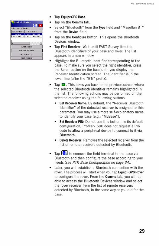
FAST Survey Field Software
• Tap Equip>GPS Base.• Tap on the Comms tab.• Select “Bluetooth” from the Type field and “Magellan BT”
from the Device field.• Tap on the Configure button. This opens the Bluetooth
Devices window.• Tap Find Receiver. Wait until FAST Survey lists the
Bluetooth identifiers of your base and rover. The list appears in a new window.
• Highlight the Bluetooth identifier corresponding to the base. To make sure you select the right identifier, press the Scroll button on the base until you display the Receiver Identification screen. The identifier is in the lower line (after the “BT:” prefix).
• Tap . This takes you back to the previous screen where the selected Bluetooth identifier remains highlighted in the list. The following actions may be performed on the selected receiver using the following buttons:• Set Receiver Name: By default, the “Receiver Bluetooth
Identifier” of the detected receiver is assigned to this parameter. You may use a more self-explanatory name to identify your base (e.g.: “MyBase”).
• Set Receiver PIN: Do not use this button. In its default configuration, ProMark 500 does not request a PIN code to allow a periphreal device to connect to it via Bluetooth.
• Delete Receiver: Removes the selected receiver from the list of remote receivers detected by Bluetooth.
• Tap to connect the field terminal to the base via Bluetooth and then configure the base according to your needs (see RTK Base Configuration on page 34).
• Later, you will establish a Bluetooth connection with the rover. The process will start when you tap Equip>GPS Rover to configure the rover. From the Comms tab, you will be able to access the Bluetooth Devices window and select the rover receiver from the list of remote receivers detected by Bluetooth, in the same way as you did for the base.
29
FAST Survey Field Software
Switching BetweenBase and Rover
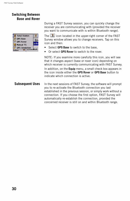
During a FAST Survey session, you can quickly change the receiver you are communicating with (provided the receiver you want to communicate with is within Bluetooth range).
The icon located in the upper-right corner of the FAST Survey window allows you to change receivers. Tap on this icon and then:• Select GPS Base to switch to the base,• Or select GPS Rover to switch to the rover.
NOTE: If you examine more carefully this icon, you will see that it changes aspect (base or rover icon) depending on which receiver is currently communicating with FAST Survey.In addition, on the Equip menu, a small check box appears in the icon inside either the GPS Rover or GPS Base button to indicate which connection is active.
Subsequent Uses In the next sessions of FAST Survey, the software will prompt you to re-activate the Bluetooth connection you last established in the previous session, or simply work without a connection. If you choose the first option, FAST Survey will automatically re-establish the connection, provided the concerned receiver is still on and within Bluetooth range.
30
Chapter 3. RTK Surveying
RTK Base Setup
Prerequisites • You will need a tripod and a tribrach (not provided) to install the base. The provided antenna extension pole fitted with a 5/8” male adaptor is also required in this configuration.
• For a long-range radio link, i.e. more than 1 mile or 1.6 km, for which the radio antenna should be placed as high as possible, Magellan recommends you install the antenna on top of an antenna pole secured on a tripod (neither of these items is provided).
• To power the radio, you need an external 9- to 28-V DC power source such as a standard 12-V DC battery (optional accessory). In this configuration, the ProMark 500 can be powered either from the same power source (recommended), using cable P/N 730477, or from its internal battery.Powering the ProMark 500 from the external battery offers two advantages: 1. Operating sessions can be extended significantly.2. The external battery operates as a trickle charger for
the ProMark 500’s internal battery.
31
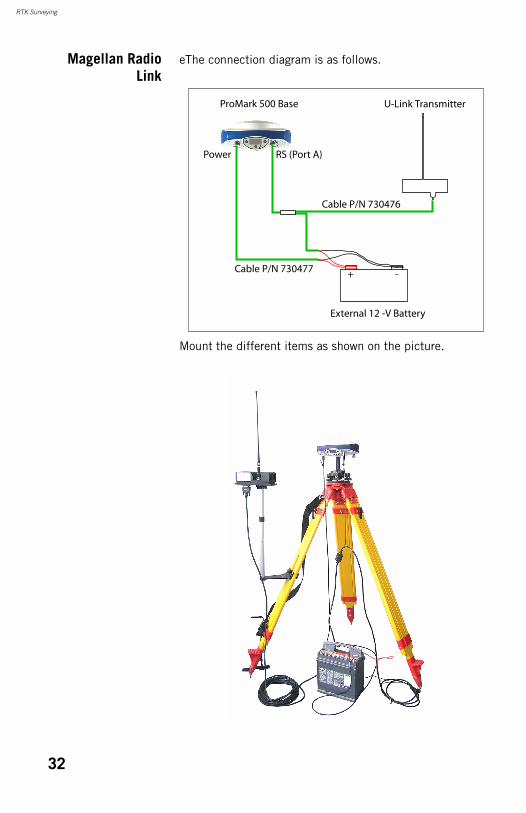
RTK Surveying
Magellan RadioLink
eThe connection diagram is as follows.
Mount the different items as shown on the picture.
External 12 -V Battery
U-Link TransmitterProMark 500 Base
Cable P/N 730476
Cable P/N 730477
Power RS (Port A)
+ -
32
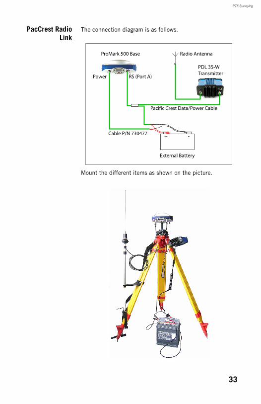
RTK Surveying
PacCrest RadioLink
The connection diagram is as follows.
Mount the different items as shown on the picture.
External Battery
PDL 35-WTransmitter
ProMark 500 Base
Pacific Crest Data/Power Cable
Radio Antenna
Cable P/N 730477
Power RS (Port A)
+ -
33
RTK Surveying
RTK Base Configuration
Prerequisites • Your base is properly set up and powered on. It is on its definitive location for the survey and the field terminal is located at less than 10 metres from the base.
• Your field terminal is on, FAST Survey is running, a Bluetooth connection has already been configured (with the base; see How FAST Survey Interfaces with ProMark 500 Via Bluetooth on page28) and a job file is open.
• In FAST Survey, tap on the Equip tab and then the GPS Base button. A message may appear asking you to confirm your choice of configuring a base. Tap Yes. This opens the Current tab of the GPS Base window.
Set Manufacturer& Model
• Set the Manufacturer (“Magellan Navigation”) and Model (“ProMark 500”) of the equipment used as the base.
Check/ChangeBluetooth
Connection
• Tap on the Comms tab. Since the Bluetooth connection was performed earlier, just check that FAST Survey is properly configured to communicate with the base. You should read:• Type = “Bluetooth”• Device = “Magellan BT”• Instr = should be set to the name you gave earlier to the
base, as seen from FAST Survey Bluetooth.
Note that the Configure button next to the Device field allows you to return to the Bluetooth Devices window through which you earlier configured the Bluetooth connection to the base (see How FAST Survey Interfaces with ProMark 500 Via Bluetooth on page28). Changes can be made now if necessary.
Set ReceiverParameters
• Using the HI measurement tool provided, perform a slant measurement of the antenna height (recommended).
• On the field terminal, tap on the Receiver tab.
34
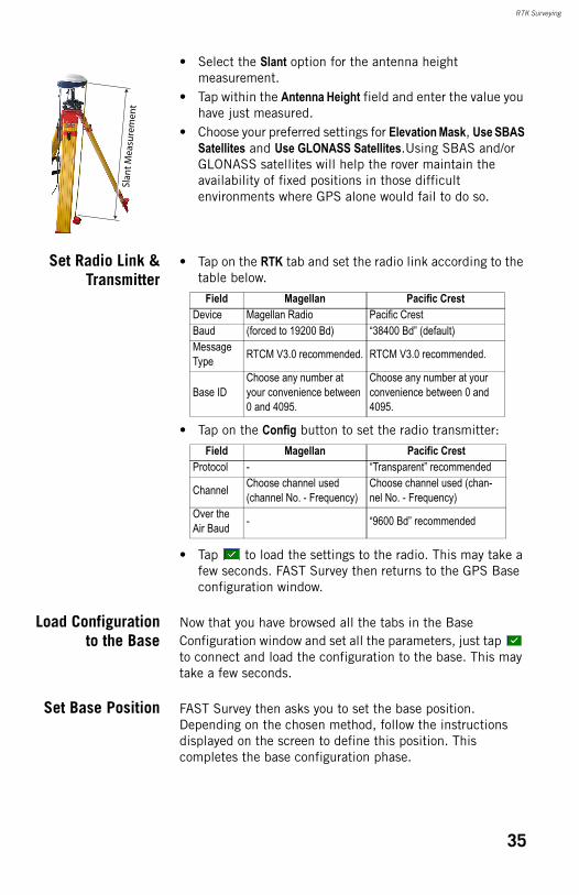
RTK Surveying
• Select the Slant option for the antenna height measurement.
• Tap within the Antenna Height field and enter the value you have just measured.
• Choose your preferred settings for Elevation Mask, Use SBAS Satellites and Use GLONASS Satellites.Using SBAS and/or GLONASS satellites will help the rover maintain the availability of fixed positions in those difficult environments where GPS alone would fail to do so.
Set Radio Link &Transmitter
• Tap on the RTK tab and set the radio link according to the table below.
• Tap on the Config button to set the radio transmitter:
• Tap to load the settings to the radio. This may take a few seconds. FAST Survey then returns to the GPS Base configuration window.
Load Configurationto the Base
Now that you have browsed all the tabs in the Base Configuration window and set all the parameters, just tap to connect and load the configuration to the base. This may take a few seconds.
Set Base Position FAST Survey then asks you to set the base position. Depending on the chosen method, follow the instructions displayed on the screen to define this position. This completes the base configuration phase.
Slan
t Mea
sure
men
t
Field Magellan Pacific CrestDevice Magellan Radio Pacific CrestBaud (forced to 19200 Bd) “38400 Bd” (default)Message Type RTCM V3.0 recommended. RTCM V3.0 recommended.
Base IDChoose any number at your convenience between 0 and 4095.
Choose any number at your convenience between 0 and 4095.
Field Magellan Pacific CrestProtocol - “Transparent” recommended
Channel Choose channel used (channel No. - Frequency)
Choose channel used (chan-nel No. - Frequency)
Over the Air Baud - “9600 Bd” recommended
35
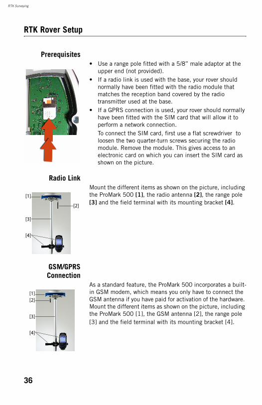
RTK Surveying
RTK Rover Setup
Prerequisites• Use a range pole fitted with a 5/8” male adaptor at the
upper end (not provided).• If a radio link is used with the base, your rover should
normally have been fitted with the radio module that matches the reception band covered by the radio transmitter used at the base.
• If a GPRS connection is used, your rover should normally have been fitted with the SIM card that will allow it to perform a network connection.To connect the SIM card, first use a flat screwdriver to loosen the two quarter-turn screws securing the radio module. Remove the module. This gives access to an electronic card on which you can insert the SIM card as shown on the picture.
Radio LinkMount the different items as shown on the picture, including the ProMark 500 [1], the radio antenna [2], the range pole [3] and the field terminal with its mounting bracket [4].
GSM/GPRSConnection
As a standard feature, the ProMark 500 incorporates a built-in GSM modem, which means you only have to connect the GSM antenna if you have paid for activation of the hardware. Mount the different items as shown on the picture, including the ProMark 500 [1], the GSM antenna [2], the range pole [3] and the field terminal with its mounting bracket [4].
[1]
[2]
[3]
[4]
[1][2]
[3]
[4]
36
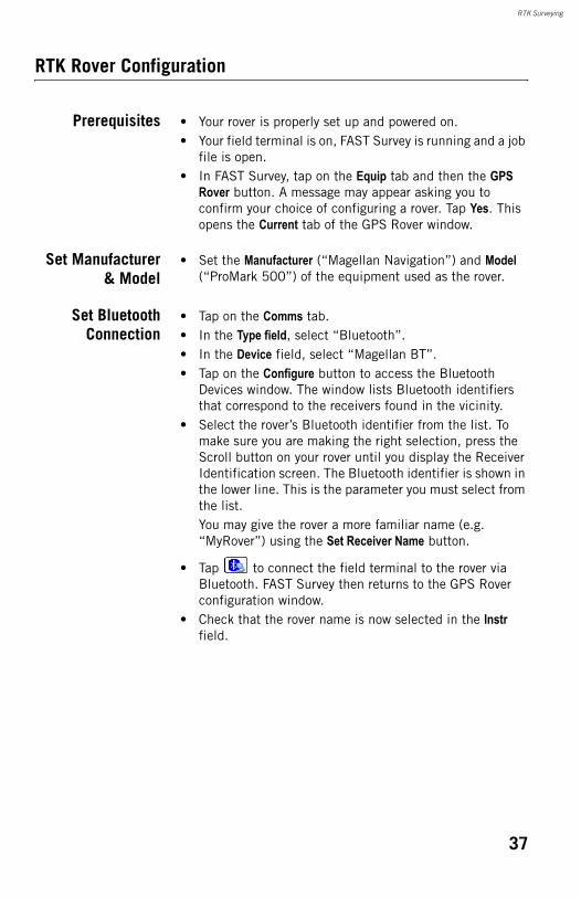
RTK Surveying
RTK Rover Configuration
Prerequisites • Your rover is properly set up and powered on. • Your field terminal is on, FAST Survey is running and a job
file is open.• In FAST Survey, tap on the Equip tab and then the GPS
Rover button. A message may appear asking you to confirm your choice of configuring a rover. Tap Yes. This opens the Current tab of the GPS Rover window.
Set Manufacturer& Model
• Set the Manufacturer (“Magellan Navigation”) and Model (“ProMark 500”) of the equipment used as the rover.
Set BluetoothConnection
• Tap on the Comms tab.• In the Type field, select “Bluetooth”.• In the Device field, select “Magellan BT”.• Tap on the Configure button to access the Bluetooth
Devices window. The window lists Bluetooth identifiers that correspond to the receivers found in the vicinity.
• Select the rover’s Bluetooth identifier from the list. To make sure you are making the right selection, press the Scroll button on your rover until you display the Receiver Identification screen. The Bluetooth identifier is shown in the lower line. This is the parameter you must select from the list.You may give the rover a more familiar name (e.g. “MyRover”) using the Set Receiver Name button.
• Tap to connect the field terminal to the rover via Bluetooth. FAST Survey then returns to the GPS Rover configuration window.
• Check that the rover name is now selected in the Instr field.
37
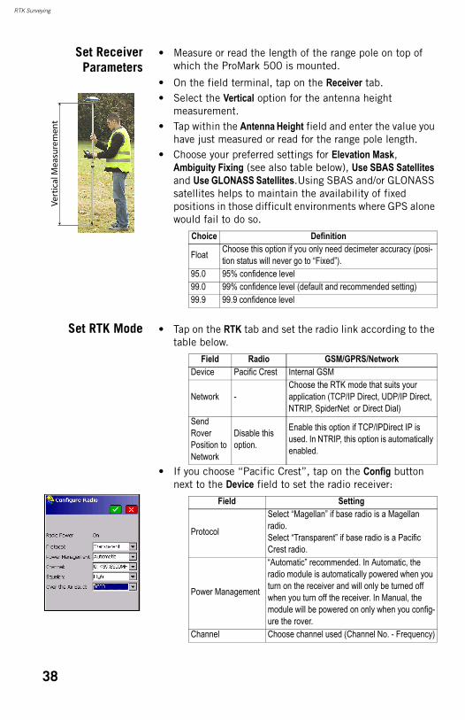
RTK Surveying
Set ReceiverParameters
• Measure or read the length of the range pole on top of which the ProMark 500 is mounted.
• On the field terminal, tap on the Receiver tab.• Select the Vertical option for the antenna height
measurement.• Tap within the Antenna Height field and enter the value you
have just measured or read for the range pole length.• Choose your preferred settings for Elevation Mask,
Ambiguity Fixing (see also table below), Use SBAS Satellites and Use GLONASS Satellites.Using SBAS and/or GLONASS satellites helps to maintain the availability of fixed positions in those difficult environments where GPS alone would fail to do so.
Set RTK Mode • Tap on the RTK tab and set the radio link according to the table below.
• If you choose “Pacific Crest”, tap on the Config button next to the Device field to set the radio receiver:
Vert
ical
Mea
sure
men
t
Choice Definition
Float Choose this option if you only need decimeter accuracy (posi-tion status will never go to “Fixed”).
95.0 95% confidence level99.0 99% confidence level (default and recommended setting)99.9 99.9 confidence level
Field Radio GSM/GPRS/NetworkDevice Pacific Crest Internal GSM
Network -Choose the RTK mode that suits your application (TCP/IP Direct, UDP/IP Direct, NTRIP, SpiderNet or Direct Dial)
Send Rover Position to Network
Disable this option.
Enable this option if TCP/IPDirect IP is used. In NTRIP, this option is automatically enabled.
Field Setting
Protocol
Select “Magellan” if base radio is a Magellan radio.Select “Transparent” if base radio is a Pacific Crest radio.
Power Management
“Automatic” recommended. In Automatic, the radio module is automatically powered when you turn on the receiver and will only be turned off when you turn off the receiver. In Manual, the module will be powered on only when you config-ure the rover.
Channel Choose channel used (Channel No. - Frequency)
38
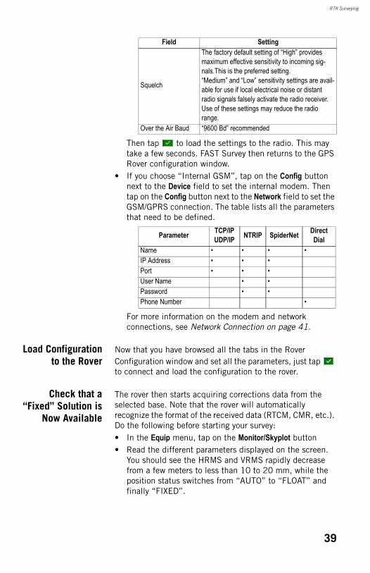
RTK Surveying
Then tap to load the settings to the radio. This may take a few seconds. FAST Survey then returns to the GPS Rover configuration window.
• If you choose “Internal GSM”, tap on the Config button next to the Device field to set the internal modem. Then tap on the Config button next to the Network field to set the GSM/GPRS connection. The table lists all the parameters that need to be defined.
For more information on the modem and network connections, see Network Connection on page 41.
Load Configurationto the Rover
Now that you have browsed all the tabs in the Rover Configuration window and set all the parameters, just tap to connect and load the configuration to the rover.
Check that a“Fixed” Solution is
Now Available
The rover then starts acquiring corrections data from the selected base. Note that the rover will automatically recognize the format of the received data (RTCM, CMR, etc.). Do the following before starting your survey:• In the Equip menu, tap on the Monitor/Skyplot button• Read the different parameters displayed on the screen.
You should see the HRMS and VRMS rapidly decrease from a few meters to less than 10 to 20 mm, while the position status switches from “AUTO” to “FLOAT” and finally “FIXED”.
Squelch
The factory default setting of “High” provides maximum effective sensitivity to incoming sig-nals.This is the preferred setting.“Medium” and “Low” sensitivity settings are avail-able for use if local electrical noise or distant radio signals falsely activate the radio receiver. Use of these settings may reduce the radio range.
Over the Air Baud “9600 Bd” recommended
Parameter TCP/IPUDP/IP NTRIP SpiderNet Direct
DialName • • • •IP Address • • •Port • • •User Name • •Password • •Phone Number •
Field Setting
39
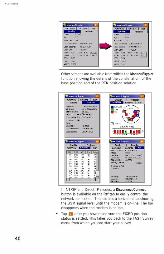
RTK Surveying
Other screens are available from within the Monitor/Skyplot function showing the details of the constellation, of the base position and of the RTK position solution:
In NTRIP and Direct IP modes, a Disconnect/Connect button is available on the Ref tab to easily control the network connection. There is also a horizontal bar showing the GSM signal level until the modem is on-line. The bar disappears when the modem is online.
• Tap after you have made sure the FIXED position status is settled. This takes you back to the FAST Survey menu from which you can start your survey.
40
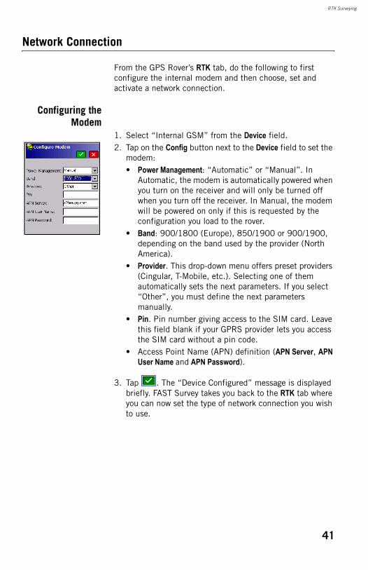
RTK Surveying
Network Connection
From the GPS Rover’s RTK tab, do the following to first configure the internal modem and then choose, set and activate a network connection.
Configuring theModem
1. Select “Internal GSM” from the Device field.2. Tap on the Config button next to the Device field to set the
modem:• Power Management: “Automatic” or “Manual”. In
Automatic, the modem is automatically powered when you turn on the receiver and will only be turned off when you turn off the receiver. In Manual, the modem will be powered on only if this is requested by the configuration you load to the rover.
• Band: 900/1800 (Europe), 850/1900 or 900/1900, depending on the band used by the provider (North America).
• Provider. This drop-down menu offers preset providers (Cingular, T-Mobile, etc.). Selecting one of them automatically sets the next parameters. If you select “Other”, you must define the next parameters manually.
• Pin. Pin number giving access to the SIM card. Leave this field blank if your GPRS provider lets you access the SIM card without a pin code.
• Access Point Name (APN) definition (APN Server, APN User Name and APN Password).
3. Tap . The “Device Configured” message is displayed briefly. FAST Survey takes you back to the RTK tab where you can now set the type of network connection you wish to use.
41
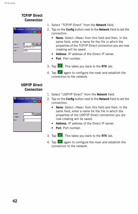
RTK Surveying
TCP/IP DirectConnection
1. Select “TCP/IP Direct” from the Network field.2. Tap on the Config button next to the Network field to set the
connection:• Name: Select <New> from this field and then, in the
same field, enter a name for the file in which the properties of the TCP/IP Direct connection you are now creating will be saved.
• Address: IP address of the Direct IP server.• Port. Port number.
3. Tap . This takes you back to the RTK tab.
4. Tap again to configure the rover and establish the connection to the network.
UDP/IP DirectConnection
1. Select “UDP/IP Direct” from the Network field.2. Tap on the Config button next to the Network field to set the
connection:• Name: Select <New> from this field and then, in the
same field, enter a name for the file in which the properties of the UDP/IP Direct connection you are now creating will be saved.
• Address: IP address of the Direct IP server.• Port. Port number.
3. Tap . This takes you back to the RTK tab.
4. Tap again to configure the rover and establish the connection to the network.
42
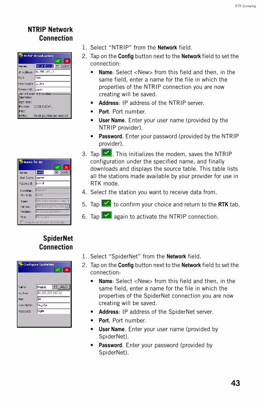
RTK Surveying
NTRIP NetworkConnection
1. Select “NTRIP” from the Network field.2. Tap on the Config button next to the Network field to set the
connection:• Name: Select <New> from this field and then, in the
same field, enter a name for the file in which the properties of the NTRIP connection you are now creating will be saved.
• Address: IP address of the NTRIP server.• Port. Port number.• User Name. Enter your user name (provided by the
NTRIP provider).• Password. Enter your password (provided by the NTRIP
provider).
3. Tap . This initializes the modem, saves the NTRIP configuration under the specified name, and finally downloads and displays the source table. This table lists all the stations made available by your provider for use in RTK mode.
4. Select the station you want to receive data from.
5. Tap to confirm your choice and return to the RTK tab.
6. Tap again to activate the NTRIP connection.
SpiderNetConnection
1. Select “SpiderNet” from the Network field.2. Tap on the Config button next to the Network field to set the
connection:• Name: Select <New> from this field and then, in the
same field, enter a name for the file in which the properties of the SpiderNet connection you are now creating will be saved.
• Address: IP address of the SpiderNet server.• Port. Port number.• User Name. Enter your user name (provided by
SpiderNet).• Password. Enter your password (provided by
SpiderNet).
43
RTK Surveying
3. Tap . This takes you back to the RTK tab.
4. Tap again to activate the SpiderNet connection.
Uploading Stakeout Points to the Field Terminal
In your office, do the following:• Connect the field terminal to your office computer using
the USB data cable.• Make sure ActiveSync is installed on your computer and is
allowed to perform USB connections. If you do not have ActiveSync installed, download the latest version from the following web page:hhttp://www.microsoft.com/windowsmobile/activesync/default.mspx
• Run GNSS Solutions on your office computer.• Open the project containing the stakeout points you want
to transfer to the field terminal as your job.• On the project map view, select all the reference and
target points making up your job.• Select Project>Upload Positions to External Device..• Select RTK Job and FAST Survey data collector.• Click OK.• Name the job (e.g. MYJOB). Keep the Selected Targets and
References option selected and click OK. This opens the Data Transfer dialog box.
• In the combo box, select Active Sync and keep Automatic transfer enabled.
• Click OK to establish the connection with the field terminal and upload the job (to \MyDevice\FAST Survey\Data\).
• After the job has been uploaded, turn off the field terminal, disconnect the USB cable and go to the field with your surveying equipment to stake out your points.
44

RTK Surveying
Running Localization
Choosing theLocalization
Method• With your job open in FAST Survey, click on the Equip tab
and then on the Localization button. This opens the Localization window with the System tab shown first.For your information, this tab shows the name of the projection selected earlier for the project (see File>Job Settings>System). Choosing another projection here would change the projection used in the job. It is your responsibility to have the right projection selected on which the localization process is going to be run.
• Tap on the GPS tab and select your localization methods for multi-point and one-point localizations. If you choose “Helmert” as the localization method, the one-point method selection is grayed.
One-Point or Multi-Point Localization
1. Tap on the Points tab. This tab allows you to define the reference points used as the input to the localization process.
For each of the available reference points, you need to enter the local coordinates and then the WGS84 coordinates, as measured by your equipment.
List of reference points you want to include in the initialization process
Edits the selected reference point
Deletes the selected reference point
Adds a new reference point to the list
Loads a list of reference points from a DAT or LOC file
Controls the content of the selected row, in the points list above, where either the geographic or local coordinates of the
reference point are displayed
Enables/disables the selected reference point for/from the localization process
Saves the list of current reference points as a LOC or DAT file
Provides access to Solution Monitoring screen
45
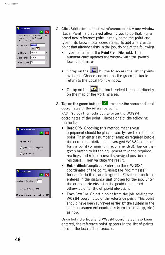
RTK Surveying
2. Click Add to define the first reference point. A new window (Local Point) is displayed allowing you to do that. For a brand new reference point, simply name the point and type in its known local coordinates. To add a reference point that already exists in the job, do one of the following:• Type its name in the Point From File field. This
automatically updates the window with the point’s local coordinates.
• Or tap on the button to access the list of points available. Choose one and tap the green button to return to the Local Point window.
• Or tap on the button to select the point directly on the map of the working area.
3. Tap on the green button ( ) to enter the name and local coordinates of the reference point.FAST Survey then asks you to enter the WGS84 coordinates of the point. Choose one of the following methods:• Read GPS. Choosing this method means your
equipment should be placed exactly over the reference point. Then enter a number of samples required before the equipment delivers an averaged WGS84 solution for the point (5 minimum recommended). Tap on the green button to let the equipment take the required readings and return a result (averaged position + residuals). Then validate the result.
• Enter latitude/Longitude. Enter the three WGS84 coordinates of the point, using the “dd.mmssss” format, for latitude and longitude. Elevation should be entered in the distance unit chosen for the job. Enter the orthometric elevation if a geoid file is used otherwise enter the ellipsoid elevation.
• From Raw File: Select a point from the job holding the WGS84 coordinates of the reference point. This point should have been surveyed earlier by the system in the same measurement conditions (same base setup, etc.) as now.
Once both the local and WGS84 coordinates have been entered, the reference point appears in the list of points used in the localization process.
46
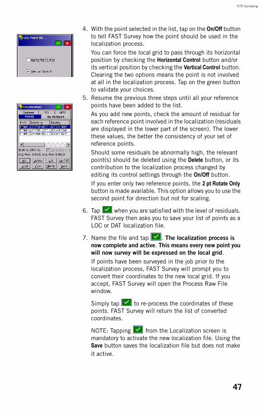
RTK Surveying
4. With the point selected in the list, tap on the On/Off button to tell FAST Survey how the point should be used in the localization process.You can force the local grid to pass through its horizontal position by checking the Horizontal Control button and/or its vertical position by checking the Vertical Control button. Clearing the two options means the point is not involved at all in the localization process. Tap on the green button to validate your choices.
5. Resume the previous three steps until all your reference points have been added to the list.As you add new points, check the amount of residual for each reference point involved in the localization (residuals are displayed in the lower part of the screen). The lower these values, the better the consistency of your set of reference points.Should some residuals be abnormally high, the relevant point(s) should be deleted using the Delete button, or its contribution to the localization process changed by editing its control settings through the On/Off button.If you enter only two reference points, the 2 pt Rotate Only button is made available. This option allows you to use the second point for direction but not for scaling.
6. Tap when you are satisfied with the level of residuals. FAST Survey then asks you to save your list of points as a LOC or DAT localization file.
7. Name the file and tap . The localization process is
now complete and active. This means every new point you
will now survey will be expressed on the local grid.If points have been surveyed in the job prior to the localization process, FAST Survey will prompt you to convert their coordinates to the new local grid. If you accept, FAST Survey will open the Process Raw File window.
Simply tap to re-process the coordinates of these points. FAST Survey will return the list of converted coordinates.
NOTE: Tapping from the Localization screen is mandatory to activate the new localization file. Using the Save button saves the localization file but does not make it active.
47
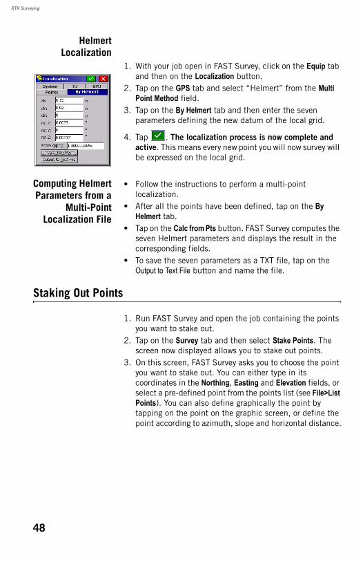
RTK Surveying
HelmertLocalization
1. With your job open in FAST Survey, click on the Equip tab and then on the Localization button.
2. Tap on the GPS tab and select “Helmert” from the Multi Point Method field.
3. Tap on the By Helmert tab and then enter the seven parameters defining the new datum of the local grid.
4. Tap . The localization process is now complete and
active. This means every new point you will now survey will be expressed on the local grid.
Computing HelmertParameters from a
Multi-PointLocalization File
• Follow the instructions to perform a multi-point localization.
• After all the points have been defined, tap on the By Helmert tab.
• Tap on the Calc from Pts button. FAST Survey computes the seven Helmert parameters and displays the result in the corresponding fields.
• To save the seven parameters as a TXT file, tap on the Output to Text File button and name the file.
Staking Out Points
1. Run FAST Survey and open the job containing the points you want to stake out.
2. Tap on the Survey tab and then select Stake Points. The screen now displayed allows you to stake out points.
3. On this screen, FAST Survey asks you to choose the point you want to stake out. You can either type in its coordinates in the Northing, Easting and Elevation fields, or select a pre-defined point from the points list (see File>List Points). You can also define graphically the point by tapping on the point on the graphic screen, or define the point according to azimuth, slope and horizontal distance.
48
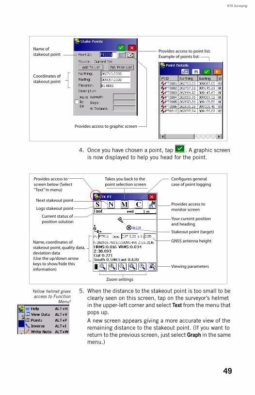
RTK Surveying
4. Once you have chosen a point, tap . A graphic screen is now displayed to help you head for the point.
Yellow helmet givesaccess to Function
Menu!
5. When the distance to the stakeout point is too small to be clearly seen on this screen, tap on the surveyor’s helmet in the upper-left corner and select Text from the menu that pops up.A new screen appears giving a more accurate view of the remaining distance to the stakeout point. (If you want to return to the previous screen, just select Graph in the same menu.)
Name of stakeout point
Coordinates of stakeout point
Provides access to point list.Example of points list:
Provides access to graphic screen
Next stakeout point
Logs stakeout point
Current status of position solution
Name, coordinates of stakeout point, quality data, deviation data(Use the up/down arrow keys to show/hide this information)
Takes you back to the point selection screen
Configures general case of point logging
Provides access to monitor screen
Provides access to screen below (Select “Text” in menu)
Your current position and heading
Stakeout point (target)
GNSS antenna height
Viewing parameters
Zoom settings
49
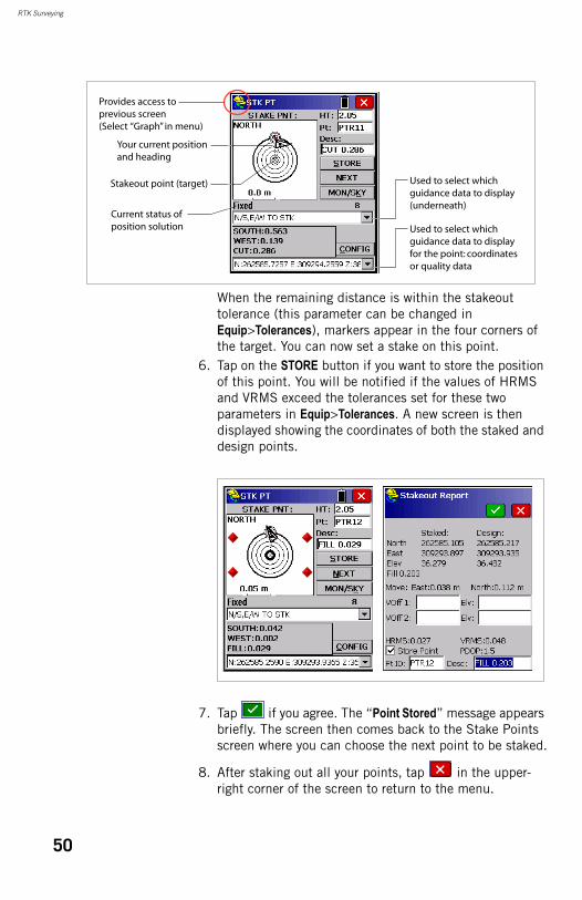
RTK Surveying
When the remaining distance is within the stakeout tolerance (this parameter can be changed in Equip>Tolerances), markers appear in the four corners of the target. You can now set a stake on this point.
6. Tap on the STORE button if you want to store the position of this point. You will be notified if the values of HRMS and VRMS exceed the tolerances set for these two parameters in Equip>Tolerances. A new screen is then displayed showing the coordinates of both the staked and design points.
7. Tap if you agree. The “Point Stored” message appears briefly. The screen then comes back to the Stake Points screen where you can choose the next point to be staked.
8. After staking out all your points, tap in the upper-right corner of the screen to return to the menu.
Stakeout point (target)
Provides access to previous screen(Select “Graph” in menu)
Your current position and heading
Used to select which guidance data to display (underneath)
Used to select which guidance data to display for the point: coordinates or quality data
Current status of position solution
50
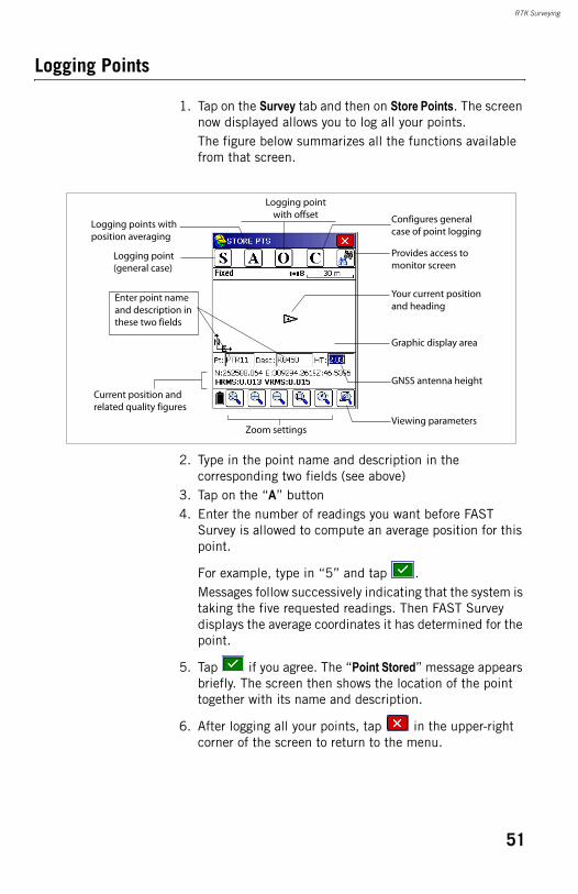
RTK Surveying
Logging Points
1. Tap on the Survey tab and then on Store Points. The screen now displayed allows you to log all your points.The figure below summarizes all the functions available from that screen.
2. Type in the point name and description in the corresponding two fields (see above)
3. Tap on the “A” button4. Enter the number of readings you want before FAST
Survey is allowed to compute an average position for this point.
For example, type in “5” and tap .Messages follow successively indicating that the system is taking the five requested readings. Then FAST Survey displays the average coordinates it has determined for the point.
5. Tap if you agree. The “Point Stored” message appears briefly. The screen then shows the location of the point together with its name and description.
6. After logging all your points, tap in the upper-right corner of the screen to return to the menu.
Configures general case of point logging
Provides access to monitor screen
Your current position and heading
Graphic display area
GNSS antenna height
Viewing parametersZoom settings
Logging points with position averaging
Logging point with offset
Logging point (general case)
Enter point name and description in these two fields
Current position and related quality figures
51
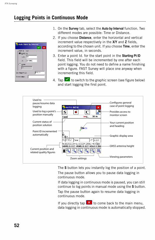
RTK Surveying
Logging Points in Continuous Mode
1. On the Survey tab, select the Auto by Interval function. Two different modes are possible: Time or Distance.
2. If you choose Distance, enter the horizontal and vertical increment value respectively in the X/Y and Z fields, according to the chosen unit. If you choose Time, enter the increment value, in seconds.
3. Enter a point Id. for the start point in the Starting Pt ID field. This field will be incremented by one after each point logging. You do not need to define a name finishing with a figure. FAST Survey will place one anyway when incrementing this field.
4. Tap to switch to the graphic screen (see figure below) and start logging the first point.
The S button lets you instantly log the position of a point.The pause button allows you to pause data logging in continuous mode.If data logging in continuous mode is paused, you can still continue to log points in manual mode using the S button.Tap the pause button again to resume data logging in continuous mode.
If you directly tap to come back to the main menu, data logging in continuous mode is automatically stopped.
Configures general case of point logging
Provides access to monitor screen
Your current position and heading
Graphic display area
GNSS antenna height
Viewing parametersZoom settings
Used to log a point’s position manually
Used to pause/resume data logging
Current status of position solution
Point ID incremented automatically
Current position and related quality figures
52

RTK Surveying
Downloading RTK Points to GNSS Solutions
• Go back to your office and connect the field terminal to your office computer using the USB data cable.
• Run GNSS Solutions on your office computer.• Open the project in which to add the points from the field.• Select Project>Download Positions from External Device..• Select RTK Results and FAST Survey data collector.• Click OK. This opens the Data Transfer dialog box.• In the combo box, select ActiveSync, enable Automatic
Transfer and click OK. This opens a new window listing all the jobs stored in the field terminal.
• Select the job you want to download (e.g. “MYJOB”) and click OK. This starts the download process.
53

RTK Surveying
54
Chapter 4. Logging Raw Data
Introduction
ProMark 500 allows you to log raw data in two different ways:• Standalone: You simply need to use the Log button to start
and stop raw data logging.Later, you will however need to do the following manually:1. Downloading phase: Rename the raw data files
collected on each site.2. Post-processing phase: Manually correct all computed
elevations for the antenna height.
• Using FAST Survey: The Survey>Log Raw GPS function allows you to fully control raw data logging. Using this method offers three advantages:.1. Antenna reduction is automatically performed during
post-processing because of the antenna height value (from the receiver properties) stored in the raw data files.
2. Ability to name the raw data file and insert time tags.3. Ability to pause/resume data logging.
By default, raw data is logged to the ProMark 500’s internal memory.Using FAST Survey, you can change the storage medium (internal memory or USB memory stick).The choice of storage medium is then valid for both data logging methods (standalone and using FAST Survey). If “USB memory stick” is selected and no USB stick is connected to the ProMark 500, then no data logging will take place.In both data logging methods, the Raw Data Logging icon on the General Status screen will start flashing when a raw data file is open for logging.
55
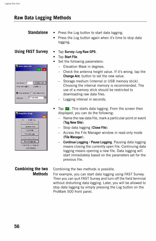
Logging Raw Data
Raw Data Logging Methods
Standalone • Press the Log button to start data logging.• Press the Log button again when it’s time to stop data
logging.
Using FAST Survey • Tap Survey>Log Raw GPS.• Tap Start File.• Set the following parameters:
– Elevation Mask in degrees.– Check the antenna height value. If it’s wrong, tap the
Change Ant. button to set the new value.– Storage medium (internal or USB memory stick).
Choosing the internal memory is recommended. The use of a memory stick should be restricted to downloading raw data files.
– Logging interval in seconds.
• Tap . This starts data logging. From the screen then displayed, you can do the following:– Name the raw data file, mark a particular point or event
(Tag New Site). – Stop data logging (Close File).– Access the File Manager window in read-only mode
(File Manager).– Continue Logging / Pause Logging. Pausing data logging
means closing the currently open file. Continuing data logging means opening a new file. Data logging will start immediately based on the parameters set for the previous file.
Combining the twoMethods
Combining the two methods is possible.For example, you can start data logging using FAST Survey. Then you can quit FAST Survey and turn off the field terminal without disturbing data logging. Later, you will be allowed to stop data logging by simply pressing the Log button on the ProMark 500 front panel.
56
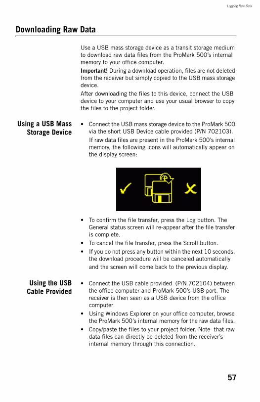
Logging Raw Data
Downloading Raw Data
Use a USB mass storage device as a transit storage medium to download raw data files from the ProMark 500’s internal memory to your office computer.Important! During a download operation, files are not deleted from the receiver but simply copied to the USB mass storage device.After downloading the files to this device, connect the USB device to your computer and use your usual browser to copy the files to the project folder.
Using a USB MassStorage Device
• Connect the USB mass storage device to the ProMark 500 via the short USB Device cable provided (P/N 702103).If raw data files are present in the ProMark 500’s internal memory, the following icons will automatically appear on the display screen:
• To confirm the file transfer, press the Log button. The General status screen will re-appear after the file transfer is complete.
• To cancel the file transfer, press the Scroll button.• If you do not press any button within the next 10 seconds,
the download procedure will be canceled automatically and the screen will come back to the previous display.
Using the USBCable Provided
• Connect the USB cable provided (P/N 702104) between the office computer and ProMark 500’s USB port. The receiver is then seen as a USB device from the office computer
• Using Windows Explorer on your office computer, browse the ProMark 500’s internal memory for the raw data files.
• Copy/paste the files to your project folder. Note that raw data files can directly be deleted from the receiver’s internal memory through this connection.
57
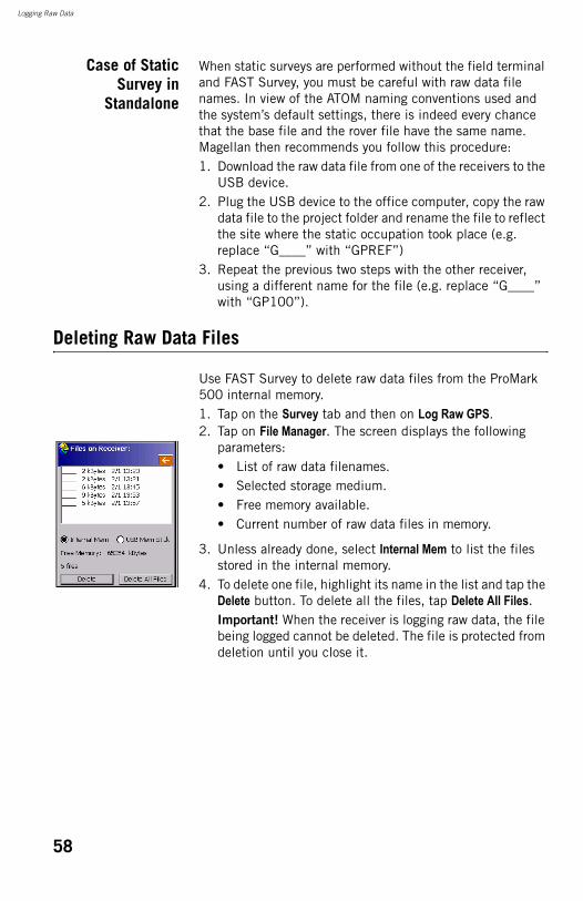
Logging Raw Data
Case of StaticSurvey in
Standalone
When static surveys are performed without the field terminal and FAST Survey, you must be careful with raw data file names. In view of the ATOM naming conventions used and the system’s default settings, there is indeed every chance that the base file and the rover file have the same name. Magellan then recommends you follow this procedure:1. Download the raw data file from one of the receivers to the
USB device.2. Plug the USB device to the office computer, copy the raw
data file to the project folder and rename the file to reflect the site where the static occupation took place (e.g. replace “G____” with “GPREF”)
3. Repeat the previous two steps with the other receiver, using a different name for the file (e.g. replace “G____” with “GP100”).
Deleting Raw Data Files
Use FAST Survey to delete raw data files from the ProMark 500 internal memory.1. Tap on the Survey tab and then on Log Raw GPS.2. Tap on File Manager. The screen displays the following
parameters:• List of raw data filenames.• Selected storage medium.• Free memory available.• Current number of raw data files in memory.
3. Unless already done, select Internal Mem to list the files stored in the internal memory.
4. To delete one file, highlight its name in the list and tap the Delete button. To delete all the files, tap Delete All Files.Important! When the receiver is logging raw data, the file being logged cannot be deleted. The file is protected from deletion until you close it.
58
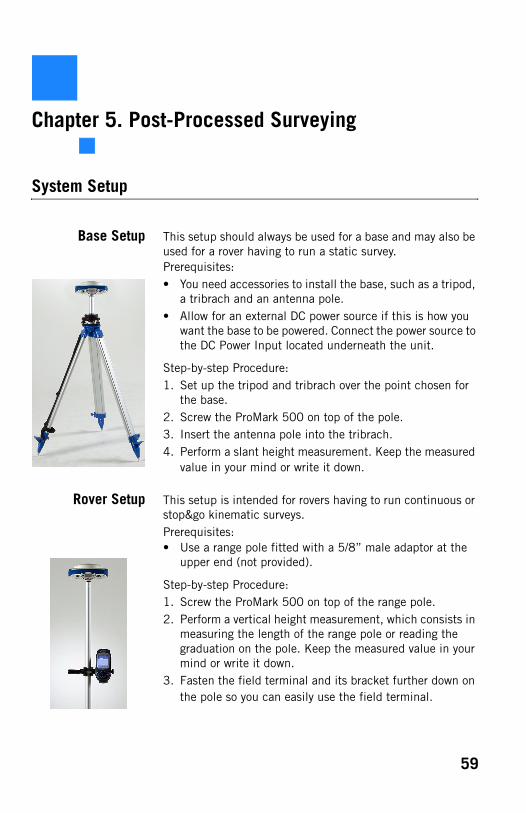
Chapter 5. Post-Processed Surveying
System Setup
Base Setup This setup should always be used for a base and may also be used for a rover having to run a static survey.Prerequisites:• You need accessories to install the base, such as a tripod,
a tribrach and an antenna pole.• Allow for an external DC power source if this is how you
want the base to be powered. Connect the power source to the DC Power Input located underneath the unit.
Step-by-step Procedure:1. Set up the tripod and tribrach over the point chosen for
the base.2. Screw the ProMark 500 on top of the pole.3. Insert the antenna pole into the tribrach.4. Perform a slant height measurement. Keep the measured
value in your mind or write it down.
Rover Setup This setup is intended for rovers having to run continuous or stop&go kinematic surveys.Prerequisites:• Use a range pole fitted with a 5/8” male adaptor at the
upper end (not provided).
Step-by-step Procedure:1. Screw the ProMark 500 on top of the range pole.2. Perform a vertical height measurement, which consists in
measuring the length of the range pole or reading the graduation on the pole. Keep the measured value in your mind or write it down.
3. Fasten the field terminal and its bracket further down on the pole so you can easily use the field terminal.
59
Post-Processed Surveying
System Configuration
Foreword Please read the following before going any further:• System configuration for post-processed surveys is
required only when FAST Survey is used to control your system. Configuring the system then only consists in activating a Bluetooth connection between the field terminal and the desired receiver.
• The FAST Survey field software is required to perform stop&go or continuous kinematic surveys, but it is optional for static surveys. Static surveys may indeed be run either with or without FAST Survey.
• When a static survey is run without FAST Survey, data collection is started/stopped directly from the receiver by pressing the Log button (see Logging Raw Data on page 55).In this case however, because the antenna height will be missing from the raw data file, you will have to measure and remember the antenna height, and later enter this information, for antenna reduction, when post-processing the static raw data file with GNSS Solutions.
• Opening a job file is mandatory when running FAST Survey but is in fact useless in the case of post-processed surveys. In addition, the notion of “base” and “rover” as presented in FAST Survey’s Equip menu is irrelevant for post-processed surveys in the sense that you don’t need to upload a “base” or rover” configuration to your receiver (except for changing the GLONASS or SBAS setting). So consider creating a job just as a means to access the FAST Survey main menu, with the following objectives: 1. Allow a Bluetooth connection to be established with
your base and rover through the Equip>GPS Base or GPS Rover button.
2. Check communication between the field terminal and the receiver using the Monitor/Skyplot function.
3. Access the Survey>Log Raw GPS function to perform your survey.
Prerequisites • Your base and rover are properly set up and powered on.• Your field terminal is on and within Bluetooth range of the
base and afterwards, of the rover.
60
Post-Processed Surveying
EstablishingBluetooth
Connection withthe Base
1. Run FAST Survey on your field terminal and create a new job.
2. Tap on the Equip tab and then on the GPS Base or GPS Rover button, whichever is the currently active button (for more convenience).NOTE: If a Bluetooth connection was established previously with your base, you just have to tap on the Connect to last bluetooth device button to restore the Bluetooth connection with the base (this would end the current procedure).
3. Tap on the Comms tab.4. Select ‘Bluetooth” in the Type field and “Magellan BT” in
the Device field.5. Tap on the Configure button next to the Device field.6. In the Bluetooth Devices window that opens, tap on the
Find Receiver button. After a few seconds, the window lists the Bluetooth identifiers of your base and rover.
7. Select the base’s Bluetooth identifier from the list.
8. Tap to connect the field terminal to the base. Then FAST survey takes you back to the Comms tab.
9. Tap to return to the FAST Survey Equip menu.
Starting Base DataCollection, Namingthe Base Raw DataFile, Programming
the End of BaseData Collection
Before starting base data collection, you need to define the elevation mask, the base antenna height, the storage medium used in the receiver and the raw data recording rate. Follow the instructions below.1. Tap on the Survey tab and then on Log Raw GPS.2. Tap on Start File. The screen lists the currently used
settings. 3. Keep or edit these settings, depending on the specific
requirements of your survey:• Elev Mask: Elevation mask, in degrees (default: 5
degrees)
61
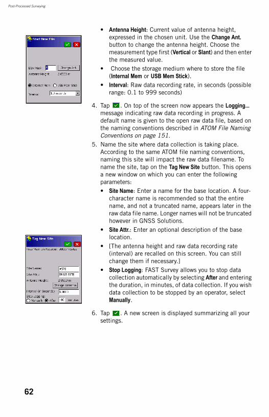
Post-Processed Surveying
• Antenna Height: Current value of antenna height, expressed in the chosen unit. Use the Change Ant. button to change the antenna height. Choose the measurement type first (Vertical or Slant) and then enter the measured value.
• Choose the storage medium where to store the file (Internal Mem or USB Mem Stick).
• Interval: Raw data recording rate, in seconds (possible range: 0.1 to 999 seconds)
4. Tap . On top of the screen now appears the Logging... message indicating raw data recording in progress. A default name is given to the open raw data file, based on the naming conventions described in ATOM File Naming Conventions on page 151.
5. Name the site where data collection is taking place. According to the same ATOM file naming conventions, naming this site will impact the raw data filename. To name the site, tap on the Tag New Site button. This opens a new window on which you can enter the following parameters:• Site Name: Enter a name for the base location. A four-
character name is recommended so that the entire name, and not a truncated name, appears later in the raw data file name. Longer names will not be truncated however in GNSS Solutions.
• Site Attr.: Enter an optional description of the base location.
• [The antenna height and raw data recording rate (interval) are recalled on this screen. You can still change them if necessary.]
• Stop Logging: FAST Survey allows you to stop data collection automatically by selecting After and entering the duration, in minutes, of data collection. If you wish data collection to be stopped by an operator, select Manually.
6. Tap . A new screen is displayed summarizing all your settings.
62
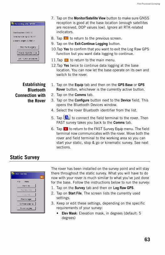
Post-Processed Surveying
7. Tap on the Monitor/Satellite View button to make sure GNSS reception is good at the base location (enough satellites are received, DOP values low). Ignore all RTK-related indicators.
8. Tap to return to the previous screen.9. Tap on the Exit-Continue Logging button.10.Tap Yes to confirm that you want to exit the Log Raw GPS
function but you want data logging to continue.
11.Tap to return to the main menu.12.Tap Yes twice to continue data logging at the base
location. You can now let the base operate on its own and switch to the rover.
EstablishingBluetooth
Connection withthe Rover
1. Tap on the Equip tab and then on the GPS Base or GPS Rover button, whichever is the currently active button.
2. Tap on the Comms tab.3. Tap on the Configure button next to the Device field. This
opens the Bluetooth Devices window.4. Select the rover Bluetooth identifier from the list.
5. Tap to connect the field terminal to the rover. Then FAST survey takes you back to the Comms tab.
6. Tap to return to the FAST Survey Equip menu. The field terminal now communicates with the rover. Move both the rover and field terminal to the working area so you can start your static, stop & go or kinematic survey. See next sections.
Static Survey
The rover has been installed on the survey point and will stay there throughout the static survey. What you will have to do now with your rover is much similar to what you’ve just done for the base. Follow the instructions below to run the survey:1. Tap on the Survey tab and then on Log Raw GPS.2. Tap on Start File. The screen lists the currently used
settings. 3. Keep or edit these settings, depending on the specific
requirements of your survey:• Elev Mask: Elevation mask, in degrees (default: 5
degrees)
63
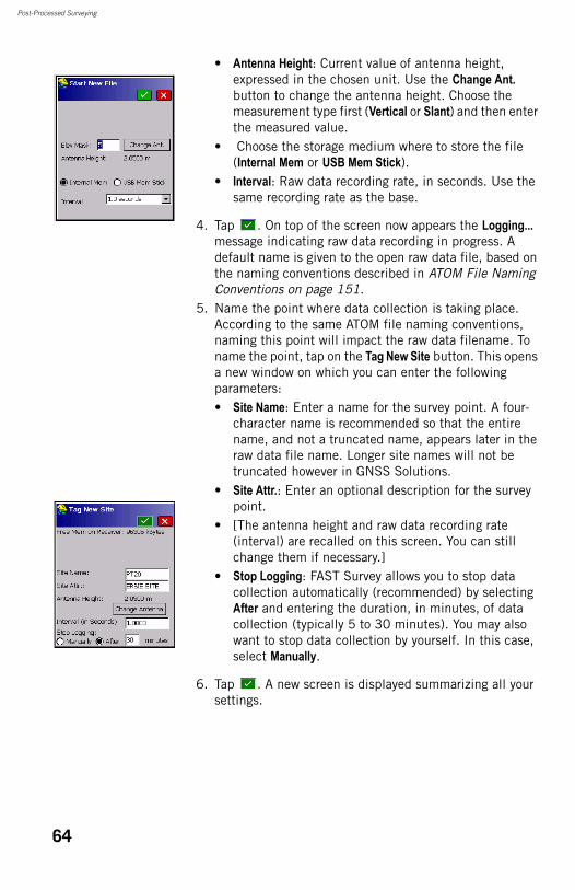
Post-Processed Surveying
• Antenna Height: Current value of antenna height, expressed in the chosen unit. Use the Change Ant. button to change the antenna height. Choose the measurement type first (Vertical or Slant) and then enter the measured value.
• Choose the storage medium where to store the file (Internal Mem or USB Mem Stick).
• Interval: Raw data recording rate, in seconds. Use the same recording rate as the base.
4. Tap . On top of the screen now appears the Logging... message indicating raw data recording in progress. A default name is given to the open raw data file, based on the naming conventions described in ATOM File Naming Conventions on page 151.
5. Name the point where data collection is taking place. According to the same ATOM file naming conventions, naming this point will impact the raw data filename. To name the point, tap on the Tag New Site button. This opens a new window on which you can enter the following parameters:• Site Name: Enter a name for the survey point. A four-
character name is recommended so that the entire name, and not a truncated name, appears later in the raw data file name. Longer site names will not be truncated however in GNSS Solutions.
• Site Attr.: Enter an optional description for the survey point.
• [The antenna height and raw data recording rate (interval) are recalled on this screen. You can still change them if necessary.]
• Stop Logging: FAST Survey allows you to stop data collection automatically (recommended) by selecting After and entering the duration, in minutes, of data collection (typically 5 to 30 minutes). You may also want to stop data collection by yourself. In this case, select Manually.
6. Tap . A new screen is displayed summarizing all your settings.
64
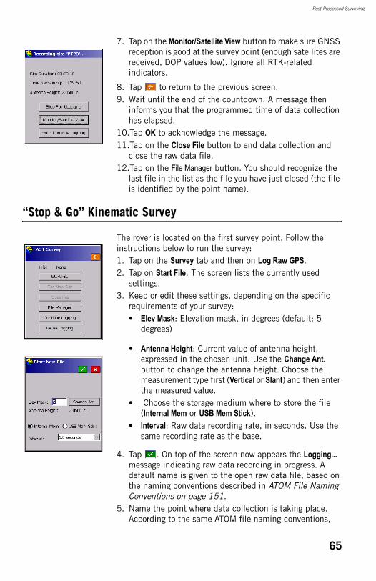
Post-Processed Surveying
7. Tap on the Monitor/Satellite View button to make sure GNSS reception is good at the survey point (enough satellites are received, DOP values low). Ignore all RTK-related indicators.
8. Tap to return to the previous screen.9. Wait until the end of the countdown. A message then
informs you that the programmed time of data collection has elapsed.
10.Tap OK to acknowledge the message.11.Tap on the Close File button to end data collection and
close the raw data file.12.Tap on the File Manager button. You should recognize the
last file in the list as the file you have just closed (the file is identified by the point name).
“Stop & Go” Kinematic Survey
The rover is located on the first survey point. Follow the instructions below to run the survey:1. Tap on the Survey tab and then on Log Raw GPS.2. Tap on Start File. The screen lists the currently used
settings. 3. Keep or edit these settings, depending on the specific
requirements of your survey:• Elev Mask: Elevation mask, in degrees (default: 5
degrees)
• Antenna Height: Current value of antenna height, expressed in the chosen unit. Use the Change Ant. button to change the antenna height. Choose the measurement type first (Vertical or Slant) and then enter the measured value.
• Choose the storage medium where to store the file (Internal Mem or USB Mem Stick).
• Interval: Raw data recording rate, in seconds. Use the same recording rate as the base.
4. Tap . On top of the screen now appears the Logging... message indicating raw data recording in progress. A default name is given to the open raw data file, based on the naming conventions described in ATOM File Naming Conventions on page 151.
5. Name the point where data collection is taking place. According to the same ATOM file naming conventions,
65
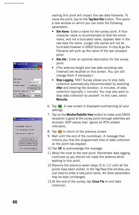
Post-Processed Surveying
naming this point will impact the raw data filename. To name the point, tap on the Tag New Site button. This opens a new window on which you can enter the following parameters:• Site Name: Enter a name for the survey point. A four-
character name is recommended so that the entire name, and not a truncated name, appears later in the raw data file name. Longer site names will not be truncated however in GNSS Solutions. In stop & go the filename will pick up the name of the last surveyed point.
• Site Attr.: Enter an optional description for the survey point.
• [The antenna height and raw data recording rate (interval) are recalled on this screen. You can still change them if necessary.]
• Stop Logging: FAST Survey allows you to stop data collection automatically (recommended) by selecting After and entering the duration, in minutes, of data collection (typically 1 minute). You may also want to stop data collection by yourself. In this case, select Manually.
6. Tap . A new screen is displayed summarizing all your settings.
7. Tap on the Monitor/Satellite View button to make sure GNSS reception is good at the survey point (enough satellites are received, DOP values low). Ignore all RTK-related indicators.
8. Tap to return to the previous screen.9. Wait until the end of the countdown. A message then
informs you that the programmed time of data collection on the point has elapsed.
10.Tap OK to acknowledge the message.11.Move the rover to the next point. Remember data logging
continues so you should not mask the antenna while walking to this point.
12.Resume the previous seven steps (5 to 11) until all the points have been visited. In the Tag New Site window, you just need to enter a new point name. All other parameters may be kept unchanged.
13.At the end of the survey, tap Close File to end data collection.
66
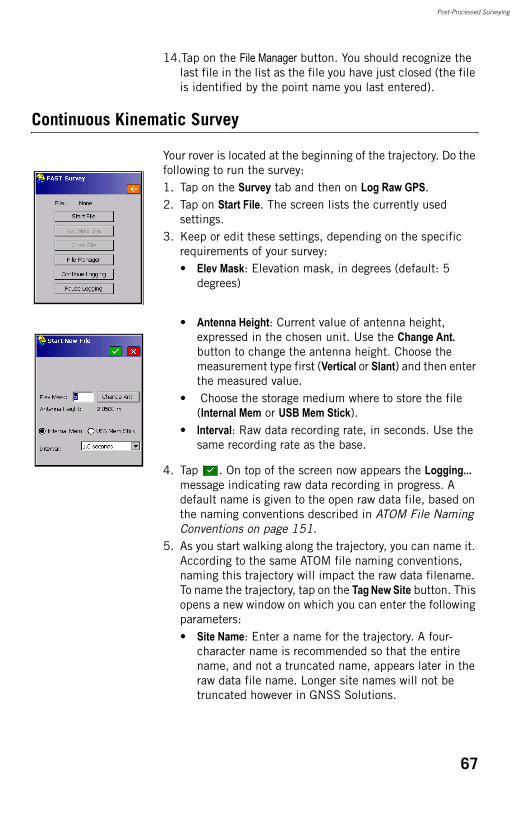
Post-Processed Surveying
14.Tap on the File Manager button. You should recognize the last file in the list as the file you have just closed (the file is identified by the point name you last entered).
Continuous Kinematic Survey
Your rover is located at the beginning of the trajectory. Do the following to run the survey:1. Tap on the Survey tab and then on Log Raw GPS.2. Tap on Start File. The screen lists the currently used
settings. 3. Keep or edit these settings, depending on the specific
requirements of your survey:• Elev Mask: Elevation mask, in degrees (default: 5
degrees)
• Antenna Height: Current value of antenna height, expressed in the chosen unit. Use the Change Ant. button to change the antenna height. Choose the measurement type first (Vertical or Slant) and then enter the measured value.
• Choose the storage medium where to store the file (Internal Mem or USB Mem Stick).
• Interval: Raw data recording rate, in seconds. Use the same recording rate as the base.
4. Tap . On top of the screen now appears the Logging... message indicating raw data recording in progress. A default name is given to the open raw data file, based on the naming conventions described in ATOM File Naming Conventions on page 151.
5. As you start walking along the trajectory, you can name it. According to the same ATOM file naming conventions, naming this trajectory will impact the raw data filename. To name the trajectory, tap on the Tag New Site button. This opens a new window on which you can enter the following parameters:• Site Name: Enter a name for the trajectory. A four-
character name is recommended so that the entire name, and not a truncated name, appears later in the raw data file name. Longer site names will not be truncated however in GNSS Solutions.
67
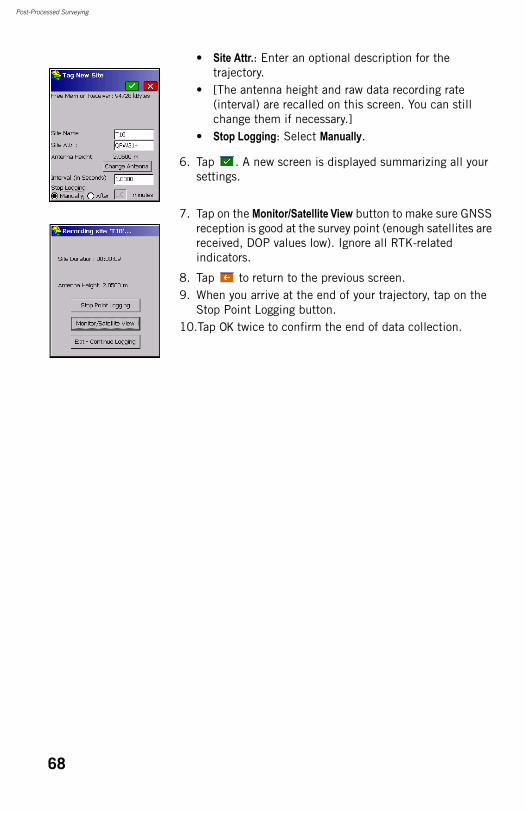
Post-Processed Surveying
• Site Attr.: Enter an optional description for the trajectory.
• [The antenna height and raw data recording rate (interval) are recalled on this screen. You can still change them if necessary.]
• Stop Logging: Select Manually.
6. Tap . A new screen is displayed summarizing all your settings.
7. Tap on the Monitor/Satellite View button to make sure GNSS reception is good at the survey point (enough satellites are received, DOP values low). Ignore all RTK-related indicators.
8. Tap to return to the previous screen.9. When you arrive at the end of your trajectory, tap on the
Stop Point Logging button.10.Tap OK twice to confirm the end of data collection.
68
Chapter 6. Precise Surveying - Field Applications & Concepts
Introduction to Precise Surveying
GNSS precise surveying relies on the use of specific algorithms involved in the processing of carrier phase measurements. Centimeter precision obtained in precise surveying results from the successful processing of these measurements.Carrier phase measurements are derived from the signals the surveying equipment receives and decodes from the visible GNSS + SBAS constellations. There are two different ways of implementing the processing algorithms, each of them defining a specific family of surveying method:• RTK real-time surveying.• Post-processed surveying
This chapter introduces the basics of the two surveying methods.Note that all Magellan RTK-capable receivers can intrinsically be used for post-processed surveys. With these receivers, post-processed surveying can be used either as a backup method or as an excellent source of comparison for checking your real-time survey results.
Key Terms andExpressions
Carrier: Refers to the electromagnetic wave carrying signals transmitted by satellites (cf. L1 and L2 carriers).Carrier phase measurements: Refers to measurements performed by a receiver from the received signals to determine the phase of the carrier at the receiver location.CPD: Carrier-Phase Differential. An acronym that refers to the processing of carrier phase measurements. Fixed (solution): Status of the position solution once RTK operation is effective and centimeter-level precision is assumed to be achieved.
69
Precise Surveying - Field Applications & Concepts
GNSS: Global Navigation Satellite System. GPS, GLONASS and the future Galileo are each a GNSS.SBAS: Satellite Based Augmentation System. A wide-area or regional system composed of geostationary satellites providing GNSS augmentation, that is a method of improving locally the performance (i.e. accuracy, reliability, availability, etc.) of a GNSS.
RTK Surveying
RTK (for Real-Time Kinematic) is a surveying method through which you ask the rover equipment to quasi-instantly determine the coordinates of your current location with centimeter precision.This section describes the implementation rules common to all surveys performed with the RTK method and presents the three basic field applications: • Logging points.• Logging points in continuous mode (trajectory).• Staking out.
Depending on the software application installed in the field terminal, more field functions may be available, like for example for road construction or civil engineering. These additional functions are all derived from the capability of the system to perform one of the three basic functions described in this section.
Key Terms andExpressions
Baseline: Distance between the base antenna phase center and the rover antenna phase center (see also GNSS Antennas and Antenna Heights on page 91). Fundamentally, the surveying system is used to determine all the components of the vector formed by the baseline.Base/rover configuration: Refers to an RTK surveying system consisting of a base and a rover. As opposed to a rover-only configuration, this system is autonomous in the sense that the surveyor has full control over the base data sent to the rover.Constellation: Set of GNSS satellites visible from a given observation point on the Earth.Data Link: Communication means allowing transfer of RTK correction data from a base to a rover.
70
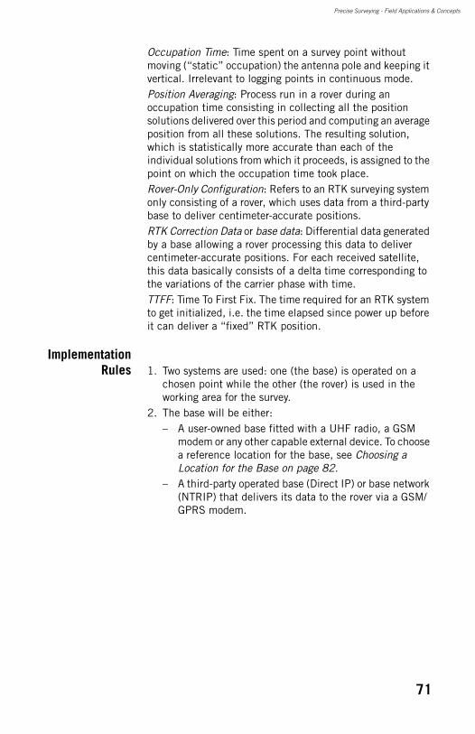
Precise Surveying - Field Applications & Concepts
Occupation Time: Time spent on a survey point without moving (“static” occupation) the antenna pole and keeping it vertical. Irrelevant to logging points in continuous mode.Position Averaging: Process run in a rover during an occupation time consisting in collecting all the position solutions delivered over this period and computing an average position from all these solutions. The resulting solution, which is statistically more accurate than each of the individual solutions from which it proceeds, is assigned to the point on which the occupation time took place.Rover-Only Configuration: Refers to an RTK surveying system only consisting of a rover, which uses data from a third-party base to deliver centimeter-accurate positions.RTK Correction Data or base data: Differential data generated by a base allowing a rover processing this data to deliver centimeter-accurate positions. For each received satellite, this data basically consists of a delta time corresponding to the variations of the carrier phase with time.TTFF: Time To First Fix. The time required for an RTK system to get initialized, i.e. the time elapsed since power up before it can deliver a “fixed” RTK position.
ImplementationRules 1. Two systems are used: one (the base) is operated on a
chosen point while the other (the rover) is used in the working area for the survey.
2. The base will be either:– A user-owned base fitted with a UHF radio, a GSM
modem or any other capable external device. To choose a reference location for the base, see Choosing a Location for the Base on page 82.
– A third-party operated base (Direct IP) or base network (NTRIP) that delivers its data to the rover via a GSM/GPRS modem.
71
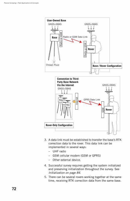
Precise Surveying - Field Applications & Concepts
3. A data link must be established to transfer the base’s RTK correction data to the rover. This data link can be implemented in several ways:– UHF radio– GSM cellular modem (GSM or GPRS)– Other external device.
4. Successful survey requires getting the system initialized and preserving initialization throughout the survey. See Initialization on page 84.
5. There can be several rovers working together at the same time, receiving RTK correction data from the same base.
Rover
Rad
io o
r G
SM
Rad
io o
r G
SM
Radio or GSM Data Link
User-Owned Base
Rover
GS
M
Inte
rnet
GPRS Data Link
Chosen Point
Base
Base
Base
Base
Connection to Third- Party Base Network Via the Internet
GNSS+SBAS
GNSS+SBAS
GNSS+SBAS
GNSS+SBAS
Rover-Only Configuration
Base / Rover Configuration
72
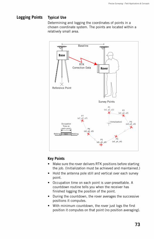
Precise Surveying - Field Applications & Concepts
Logging Points Typical UseDetermining and logging the coordinates of points in a chosen coordinate system. The points are located within a relatively small area.
Key Points• Make sure the rover delivers RTK positions before starting
the job. (Initialization must be achieved and maintained.)• Hold the antenna pole still and vertical over each survey
point.• Occupation time on each point is user-presettable. A
countdown routine tells you when the receiver has finished logging the position of the point.
• During the countdown, the rover averages the successive positions it computes.
• With minimum countdown, the rover just logs the first position it computes on that point (no position averaging).
(Initialization)
Rover
Baseline
Reference Point
Survey Points
Base
(x1, y1, z1)
(x2, y2, z2)
(x3, y3, z3)
(x4, y4, z4)(x5, y5, z5)
(x6, y6, z6)
(x7, y7, z7)
RTKCorrection Data
P1
P2
P3
P4P5
P6
P7
Occupation Time on
each point
WalkingWalking Still
73
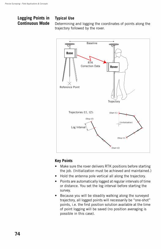
Precise Surveying - Field Applications & Concepts
Logging Points inContinuous Mode
Typical UseDetermining and logging the coordinates of points along the trajectory followed by the rover.
Key Points• Make sure the rover delivers RTK positions before starting
the job. (Initialization must be achieved and maintained.)• Hold the antenna pole vertical all along the trajectory.• Points are automatically logged at regular intervals of time
or distance. You set the log interval before starting the survey.
• Because you will be steadily walking along the surveyed trajectory, all logged points will necessarily be “one-shot” points, i.e. the first position solution available at the time of point logging will be saved (no position averaging is possible in this case).
(Initialization)
(Start t1)
(Start t2)
(Stop t1)
(Stop t2)
Rover
Baseline
Reference Point
Trajectory
Trajectories (t1, t2):
Base
RTKCorrection Data
Log Interval
74
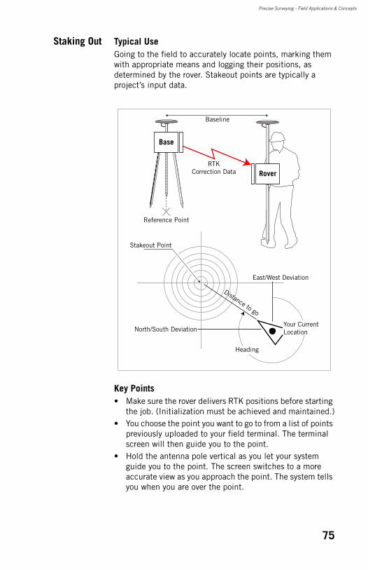
Precise Surveying - Field Applications & Concepts
Staking Out Typical UseGoing to the field to accurately locate points, marking them with appropriate means and logging their positions, as determined by the rover. Stakeout points are typically a project’s input data.
Key Points• Make sure the rover delivers RTK positions before starting
the job. (Initialization must be achieved and maintained.)• You choose the point you want to go to from a list of points
previously uploaded to your field terminal. The terminal screen will then guide you to the point.
• Hold the antenna pole vertical as you let your system guide you to the point. The screen switches to a more accurate view as you approach the point. The system tells you when you are over the point.
Rover
Baseline
Reference Point
Base
RTKCorrection Data
Stakeout Point
East/West Deviation
North/South Deviation
Distance to go
Your Current Location
Heading
75
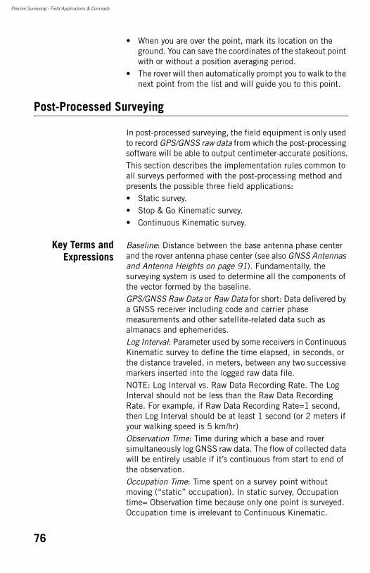
Precise Surveying - Field Applications & Concepts
• When you are over the point, mark its location on the ground. You can save the coordinates of the stakeout point with or without a position averaging period.
• The rover will then automatically prompt you to walk to the next point from the list and will guide you to this point.
Post-Processed Surveying
In post-processed surveying, the field equipment is only used to record GPS/GNSS raw data from which the post-processing software will be able to output centimeter-accurate positions.This section describes the implementation rules common to all surveys performed with the post-processing method and presents the possible three field applications:• Static survey.• Stop & Go Kinematic survey.• Continuous Kinematic survey.
Key Terms andExpressions
Baseline: Distance between the base antenna phase center and the rover antenna phase center (see also GNSS Antennas and Antenna Heights on page 91). Fundamentally, the surveying system is used to determine all the components of the vector formed by the baseline.GPS/GNSS Raw Data or Raw Data for short: Data delivered by a GNSS receiver including code and carrier phase measurements and other satellite-related data such as almanacs and ephemerides.Log Interval: Parameter used by some receivers in Continuous Kinematic survey to define the time elapsed, in seconds, or the distance traveled, in meters, between any two successive markers inserted into the logged raw data file.NOTE: Log Interval vs. Raw Data Recording Rate. The Log Interval should not be less than the Raw Data Recording Rate. For example, if Raw Data Recording Rate=1 second, then Log Interval should be at least 1 second (or 2 meters if your walking speed is 5 km/hr)Observation Time: Time during which a base and rover simultaneously log GNSS raw data. The flow of collected data will be entirely usable if it’s continuous from start to end of the observation.Occupation Time: Time spent on a survey point without moving (“static” occupation). In static survey, Occupation time= Observation time because only one point is surveyed. Occupation time is irrelevant to Continuous Kinematic.
76
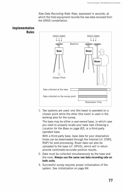
Precise Surveying - Field Applications & Concepts
Raw Data Recording Rate: Rate, expressed in seconds, at which the field equipment records the raw data received from the GNSS constellation.
ImplementationRules
1. Two systems are used: one (the base) is operated on a chosen point while the other (the rover) is used in the working area for the survey.The base may be either a user-owned base, in which case you need to properly locate your base (see Choosing a Location for the Base on page 82), or a third-party operated base.With a third-party base, base data for your observation times can be downloaded through the Internet (cf. CORS, RGP) for post-processing. Rover data can also be uploaded to the base (cf. OPUS), which will in return provide centimeter-accurate position results.
2. Data must be collected simultaneously by the base and the rover. Always use the same raw data recording rate on
both units. 3. Successful survey requires proper initialization of the
system. See Initialization on page 84.
Chosen Point
Base Rover
GNSS+SBAS GNSS+SBAS
Rover
Data collected at the base
Data collected on the survey point
Observation Time
Baseline
77
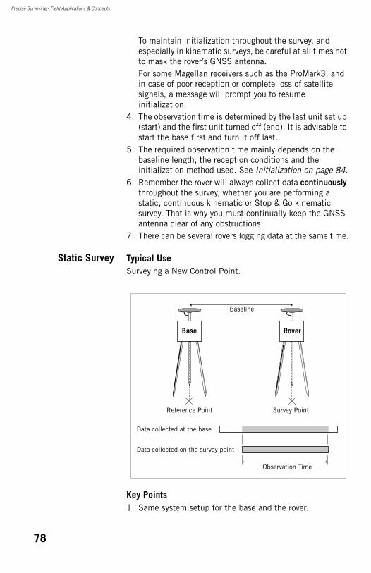
Precise Surveying - Field Applications & Concepts
To maintain initialization throughout the survey, and especially in kinematic surveys, be careful at all times not to mask the rover’s GNSS antenna.For some Magellan receivers such as the ProMark3, and in case of poor reception or complete loss of satellite signals, a message will prompt you to resume initialization.
4. The observation time is determined by the last unit set up (start) and the first unit turned off (end). It is advisable to start the base first and turn it off last.
5. The required observation time mainly depends on the baseline length, the reception conditions and the initialization method used. See Initialization on page 84.
6. Remember the rover will always collect data continuously throughout the survey, whether you are performing a static, continuous kinematic or Stop & Go kinematic survey. That is why you must continually keep the GNSS antenna clear of any obstructions.
7. There can be several rovers logging data at the same time.
Static Survey Typical UseSurveying a New Control Point.
Key Points1. Same system setup for the base and the rover.
Reference Point
Data collected at the base
Data collected on the survey point
Observation Time
Baseline
Base
Survey Point
Rover
78
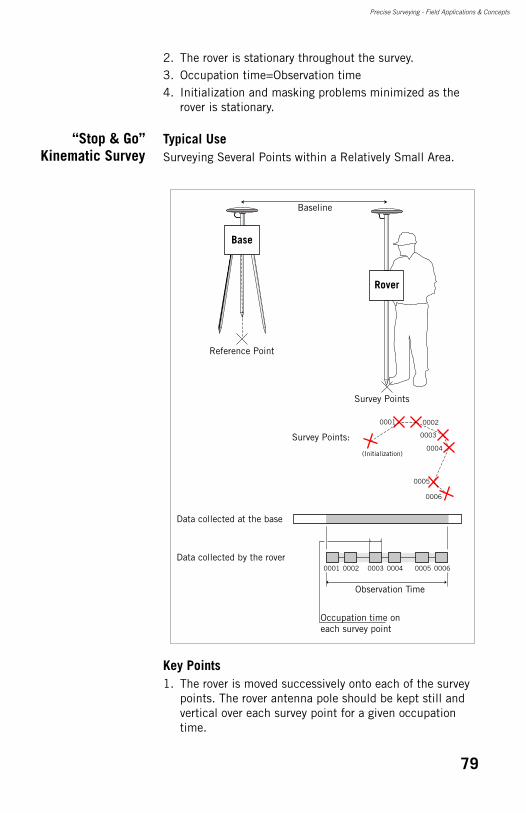
Precise Surveying - Field Applications & Concepts
2. The rover is stationary throughout the survey.3. Occupation time=Observation time4. Initialization and masking problems minimized as the
rover is stationary.
“Stop & Go”Kinematic Survey
Typical UseSurveying Several Points within a Relatively Small Area.
Key Points1. The rover is moved successively onto each of the survey
points. The rover antenna pole should be kept still and vertical over each survey point for a given occupation time.
Survey Points:
Data collected at the base
Data collected by the rover0001
0001
0002
0002
0003
0003
0004
0004
0005
0005
0006
0006
(Initialization)
Rover
Baseline
Reference Point
Survey Points
Base
Observation Time
Occupation time on each survey point
79
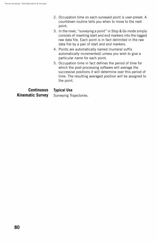
Precise Surveying - Field Applications & Concepts
2. Occupation time on each surveyed point is user-preset. A countdown routine tells you when to move to the next point.
3. In the rover, “surveying a point” in Stop & Go mode simply consists of inserting start and end markers into the logged raw data file. Each point is in fact delimited in the raw data file by a pair of start and end markers.
4. Points are automatically named (numeral suffix automatically incremented) unless you wish to give a particular name for each point.
5. Occupation time in fact defines the period of time for which the post-processing software will average the successive positions it will determine over this period of time. The resulting averaged position will be assigned to the point.
ContinuousKinematic Survey
Typical UseSurveying Trajectories.
80
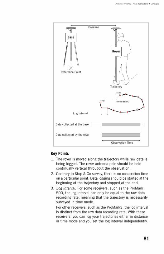
Precise Surveying - Field Applications & Concepts
Key Points1. The rover is moved along the trajectory while raw data is
being logged. The rover antenna pole should be held continually vertical througout the observation.
2. Contrary to Stop & Go survey, there is no occupation time on a particular point. Data logging should be started at the beginning of the trajectory and stopped at the end.
3. Log interval. For some receivers, such as the ProMark 500, the log interval can only be equal to the raw data recording rate, meaning that the trajectory is necessarily surveyed in time mode.For other receivers, such as the ProMark3, the log interval is distinct from the raw data recording rate. With these receivers, you can log your trajectories either in distance or time mode and you set the log interval independently.
Data collected at the base
Data collected by the rover
(Initialization)
(Start)
(Stop)
Rover
Baseline
Reference Point
Trajectory
Base
Observation Time
Log Interval
81
Precise Surveying - Field Applications & Concepts
In distance mode, a new marker is created every x meters. In time mode, a new marker is created every x seconds, where ”x” is the log interval.While you are walking along the trajectory, the rover inserts new markers into the logged raw data file according to the chosen log interval. Each marker is named as a point. The name includes a numeral suffix that is automatically incremented for each new logged marker. You must take care however to use a log interval that is compatible with the raw data recording rate:
In time mode:log interval (s) >2 x raw data recording rate (s)In distance mode:log interval (m) > 2 x walking speed (m/s) x raw data recording rate (s)
4. Number of trajectories in a single file. Some receivers, such as the ProMark 500, allow you to log a single trajectory into a raw data file. Some others, like the ProMark3, allow you to enter several start/stop markers in the same file meaning that several trajectories can be logged in the same file.
Choosing a Location for the Base
The location of the base is fundamental for the success of your survey. Whether you are in post-processing or real-time mode and your receivers are single- or dual-frequency, remember the rover position will always be computed relative to the base position. Any inaccuracy in the base position will inevitably be transferred to the position computed by the rover.This section discusses the two basic criteria to be taken into account when installing a base:1. GNSS reception conditions2. Base position known or unknown?
When a base radio is used, there is a third criterion to be taken into account in the choice of the base location, which is the ability to install the radio antenna as high as possible, with a minimum of obstructions to the working area, so that the radio range can be as good as expected.
First Criterion:GNSS Reception
Conditions
Make sure the base is sited in a clear area giving the best possible view of the sky.
82

Precise Surveying - Field Applications & Concepts
When this is possible, avoid trees, buildings or any high obstacles in the vicinity of the base.Having a clear view of the sky will allow the base to collect data from a maximum of visible satellites, which is highly recommended to perform a successful, accurate and fast survey.You should pay attention to low-level satellite signals coming through trees, which may have a more adverse effect upon system performance than those completely masked.
Second Criterion:Base Position
Known orUnknown?
In addition to the good reception conditions required at the base, you must also think about whether the base position should be known with great precision or not. The explanations below will help you understand what you need in terms of base position accuracy.1. If you want to obtain absolute, centimeter-accurate
positions attached to a particular coordinate system for all your surveyed points, then the base position must be known with the same centimeter accuracy.If the chosen position for the base is unknown whereas you need centimeter accuracy for this point in the coordinate system used, you can determine it through a static post-processing survey. You will however need a reference position to determine this point.
Base
Properly received satellites
Avoid multi-paths
Masked satellite Masked satellite
Poor
qua
lity,
low
-leve
l sig
nal
83
Precise Surveying - Field Applications & Concepts
2. If you are only interested in performing relative
measurements (i.e. positions of points relatively to other points), then the base can be installed on an unknown point meeting the reception requirements. In this case, the position to be entered in the base can be accurate only to within a few meters.Caution! In this case, keep in mind that you will not be able to attach your points to a known coordinate system unless later you accurately determine one of these points in the desired coordinate system. If you are using field software such as Magellan FAST Survey, you can also use the Localization function to attach your job to a local system.There are some disadvantages that you should be aware of when installing a base on an unknown point. For every 15 meters of error between the estimated base coordinates and the true base coordinates, one part-per-million (ppm) of relative error will be introduced into the computed vector between base and rover, plus the absolute difference between the computed base position and the real base position.For example, assume that the coordinates assigned to the base point are 30 meters off the true base position. This 30-meter offset from truth will produce 2 ppm (0.002 m per kilometer or 0.010 ft per mile) of error in the vector between base and rover.If the rover is 5 kilometers (3 miles) from the base, this will produce 0.010 m (0.030 ft) of error in the vector. In most cases, the base receiver will estimate its position to better than 30 meters (probably closer to 10-20 meters), but an error of 50 meters is possible.If you plan to use an estimated position for the base, keep the vector lengths between the base and rover short and ensure the added error is not significant for the survey you are performing.
Initialization
Preamble Initialization is the process through which your real-time receiver or post-processing software can solve the integer ambiguity inherent in the carrier phase processing.Solving integer ambiguity is a prerequisite for the receiver or software to be able to deliver centimeter-accurate positions.
84
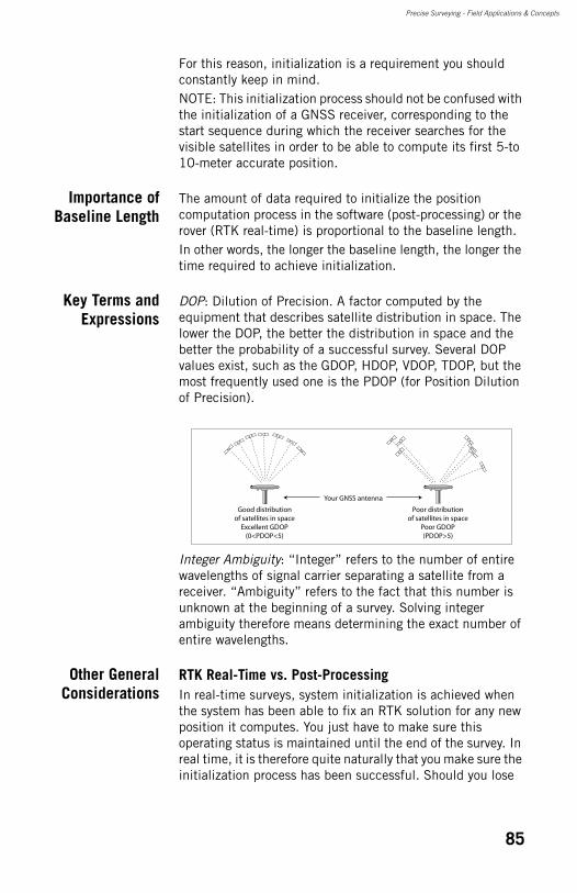
Precise Surveying - Field Applications & Concepts
For this reason, initialization is a requirement you should constantly keep in mind.NOTE: This initialization process should not be confused with the initialization of a GNSS receiver, corresponding to the start sequence during which the receiver searches for the visible satellites in order to be able to compute its first 5-to 10-meter accurate position.
Importance ofBaseline Length
The amount of data required to initialize the position computation process in the software (post-processing) or the rover (RTK real-time) is proportional to the baseline length.In other words, the longer the baseline length, the longer the time required to achieve initialization.
Key Terms andExpressions
DOP: Dilution of Precision. A factor computed by the equipment that describes satellite distribution in space. The lower the DOP, the better the distribution in space and the better the probability of a successful survey. Several DOP values exist, such as the GDOP, HDOP, VDOP, TDOP, but the most frequently used one is the PDOP (for Position Dilution of Precision).
Integer Ambiguity: “Integer” refers to the number of entire wavelengths of signal carrier separating a satellite from a receiver. “Ambiguity” refers to the fact that this number is unknown at the beginning of a survey. Solving integer ambiguity therefore means determining the exact number of entire wavelengths.
Other GeneralConsiderations
RTK Real-Time vs. Post-ProcessingIn real-time surveys, system initialization is achieved when the system has been able to fix an RTK solution for any new position it computes. You just have to make sure this operating status is maintained until the end of the survey. In real time, it is therefore quite naturally that you make sure the initialization process has been successful. Should you lose
Good distributionof satellites in space
Excellent GDOP(0<PDOP<5)
Poor distributionof satellites in space
Poor GDOP(PDOP>5)
Your GNSS antenna
85
Precise Surveying - Field Applications & Concepts
the “RTK” position status, then this would mean the system has lost initialization and you should act to restore it.In post-processed surveys, there is the same need for initialization except that the system is not always able to inform you, in real time, that this requirement is met. Remember that in this type of survey, your system is just a raw data collector.It is only subsequently, when back at the office to post-process the raw data that you will see if the complete set of collected data results in successful and sustained initialization.
Kinematic vs. StaticIn static surveys, the risk of unsuccessful initialization is significantly lessened by the fact that the GNSS antenna is motionless and the system is operated for relatively long recording sessions with the best possible view of the sky.This may not be true for kinematic surveys during which the rover is moved from place to place, with real risks of:• Masking the GNSS antenna causing lock on satellites to
be lost.• Stopping recording sessions before enough data has been
collected to guarantee initialization.
For this reason, you should be aware of the initialization issue and so take all the necessary steps to make sure initialization will not only be achieved but also preserved until the end of your kinematic surveys.
Single-Frequency vs. Dual-FrequencyGNSS dual-frequency receivers need less data and time to get initialized. However, recent developments have allowed single-frequency receivers to significantly improve their performance on that particular point and so to reduce the gap that separate them from dual-frequency systems.
Strategies forSecuring
Initialization
When starting a survey, you will sometimes be asked to choose an initialization method (more particularly if you are using a single-frequency receiver). The selected method tells the system how it should deal with initialization. Some of these methods can make initialization easier and faster, resulting in the following:• Reduction of the observation time in post-processing.• Reduction of the TTFF in RTK real-time.
86
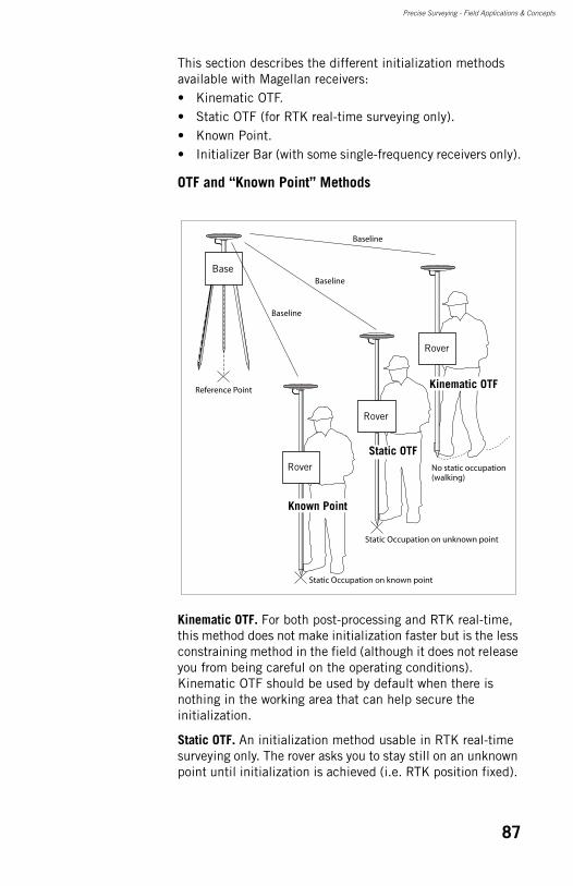
Precise Surveying - Field Applications & Concepts
This section describes the different initialization methods available with Magellan receivers:• Kinematic OTF.• Static OTF (for RTK real-time surveying only).• Known Point.• Initializer Bar (with some single-frequency receivers only).
OTF and “Known Point” Methods
Kinematic OTF. For both post-processing and RTK real-time, this method does not make initialization faster but is the less constraining method in the field (although it does not release you from being careful on the operating conditions). Kinematic OTF should be used by default when there is nothing in the working area that can help secure the initialization.
Static OTF. An initialization method usable in RTK real-time surveying only. The rover asks you to stay still on an unknown point until initialization is achieved (i.e. RTK position fixed).
Rover
Baseline
Baseline
Baseline
Reference Point
Base
Rover
Rover No static occupation(walking)
Static Occupation on unknown point
Static Occupation on known point
Static OTF
Known Point
Kinematic OTF
87
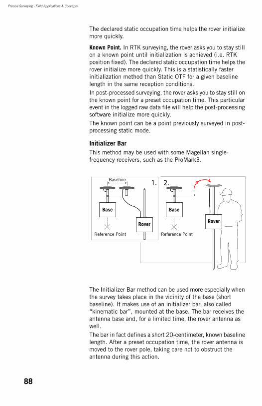
Precise Surveying - Field Applications & Concepts
The declared static occupation time helps the rover initialize more quickly.
Known Point. In RTK surveying, the rover asks you to stay still on a known point until initialization is achieved (i.e. RTK position fixed). The declared static occupation time helps the rover initialize more quickly. This is a statistically faster initialization method than Static OTF for a given baseline length in the same reception conditions. In post-processed surveying, the rover asks you to stay still on the known point for a preset occupation time. This particular event in the logged raw data file will help the post-processing software initialize more quickly.The known point can be a point previously surveyed in post-processing static mode.
Initializer BarThis method may be used with some Magellan single-frequency receivers, such as the ProMark3.
The Initializer Bar method can be used more especially when the survey takes place in the vicinity of the base (short baseline). It makes use of an initializer bar, also called “kinematic bar”, mounted at the base. The bar receives the antenna base and, for a limited time, the rover antenna as well.The bar in fact defines a short 20-centimeter, known baseline length. After a preset occupation time, the rover antenna is moved to the rover pole, taking care not to obstruct the antenna during this action.
Base
RoverRover
Baseline
Reference Point
1. 2.
Base
Reference Point
88
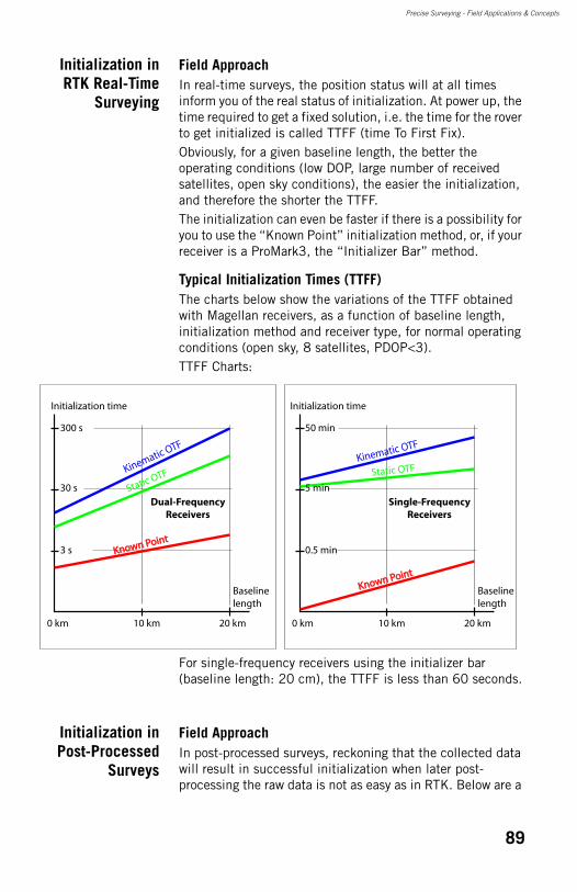
Precise Surveying - Field Applications & Concepts
Initialization inRTK Real-Time
Surveying
Field ApproachIn real-time surveys, the position status will at all times inform you of the real status of initialization. At power up, the time required to get a fixed solution, i.e. the time for the rover to get initialized is called TTFF (time To First Fix). Obviously, for a given baseline length, the better the operating conditions (low DOP, large number of received satellites, open sky conditions), the easier the initialization, and therefore the shorter the TTFF.The initialization can even be faster if there is a possibility for you to use the “Known Point” initialization method, or, if your receiver is a ProMark3, the “Initializer Bar” method.
Typical Initialization Times (TTFF)The charts below show the variations of the TTFF obtained with Magellan receivers, as a function of baseline length, initialization method and receiver type, for normal operating conditions (open sky, 8 satellites, PDOP<3).TTFF Charts:
For single-frequency receivers using the initializer bar (baseline length: 20 cm), the TTFF is less than 60 seconds.
Initialization inPost-Processed
Surveys
Field ApproachIn post-processed surveys, reckoning that the collected data will result in successful initialization when later post-processing the raw data is not as easy as in RTK. Below are a
10 km0 km 20 km
Baselinelength
Initialization time
3 s
300 s
30 s
Kinematic OTF
Static OTF
Known PointKnown Point
Dual-FrequencyReceivers
Single-FrequencyReceivers
10 km0 km 20 km
Baselinelength
Initialization time
0.5 min
50 min
5 min
Kinematic OTF
Static OTF
Known PointKnown Point
89
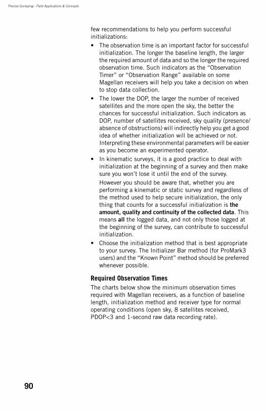
Precise Surveying - Field Applications & Concepts
few recommendations to help you perform successful initializations:• The observation time is an important factor for successful
initialization. The longer the baseline length, the larger the required amount of data and so the longer the required observation time. Such indicators as the “Observation Timer” or “Observation Range” available on some Magellan receivers will help you take a decision on when to stop data collection.
• The lower the DOP, the larger the number of received satellites and the more open the sky, the better the chances for successful initialization. Such indicators as DOP, number of satellites received, sky quality (presence/absence of obstructions) will indirectly help you get a good idea of whether initialization will be achieved or not. Interpreting these environmental parameters will be easier as you become an experimented operator.
• In kinematic surveys, it is a good practice to deal with initialization at the beginning of a survey and then make sure you won’t lose it until the end of the survey.However you should be aware that, whether you are performing a kinematic or static survey and regardless of the method used to help secure initialization, the only thing that counts for a successful initialization is the
amount, quality and continuity of the collected data. This means all the logged data, and not only those logged at the beginning of the survey, can contribute to successful initialization.
• Choose the initialization method that is best appropriate to your survey. The Initializer Bar method (for ProMark3 users) and the “Known Point” method should be preferred whenever possible.
Required Observation TimesThe charts below show the minimum observation times required with Magellan receivers, as a function of baseline length, initialization method and receiver type for normal operating conditions (open sky, 8 satellites received, PDOP<3 and 1-second raw data recording rate).
90
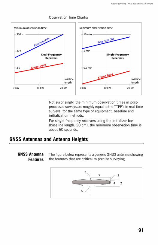
Precise Surveying - Field Applications & Concepts
Observation Time Charts:
Not surprisingly, the minimum observation times in post-processed surveys are roughly equal to the TTFF’s in real-time surveys, for the same type of equipment, baseline and initialization methods.For single-frequency receivers using the initializer bar (baseline length: 20 cm), the minimum observation time is about 60 seconds.
GNSS Antennas and Antenna Heights
GNSS AntennaFeatures
The figure below represents a generic GNSS antenna showing the features that are critical to precise surveying.
10 km0 km 20 km
Baselinelength
Minimum observation time
3 s
300 s
30 s
Kinematic OTF
Known PointKnown Point
Dual-FrequencyReceivers
Single-FrequencyReceivers
10 km0 km 20 km
Baselinelength
Minimum observation time
0.5 min
50 min
5 min
Kinematic OTF
Known PointKnown Point
1
6
5
2
3
4
91
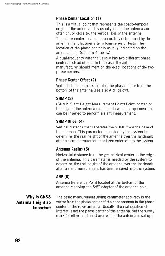
Precise Surveying - Field Applications & Concepts
Phase Center Location (1)This is a virtual point that represents the spatio-temporal origin of the antenna. It is usually inside the antenna and often on, or close to, the vertical axis of the antenna.The phase center location is accurately determined by the antenna manufacturer after a long series of tests. The location of the phase center is usually indicated on the antenna itself (see also 4. below). A dual-frequency antenna usually has two different phase centers instead of one. In this case, the antenna manufacturer should mention the exact locations of the two phase centers.
Phase Center Offset (2)Vertical distance that separates the phase center from the bottom of the antenna (see also ARP below).
SHMP (3)(SHMP=Slant Height Measurement Point) Point located on the edge of the antenna radome into which a tape measure can be inserted to perform a slant measurement.
SHMP Offset (4)Vertical distance that separates the SHMP from the base of the antenna. This parameter is needed by the system to determine the real height of the antenna over the landmark after a slant measurement has been entered into the system.
Antenna Radius (5)Horizontal distance from the geometrical center to the edge of the antenna. This parameter is needed by the system to determine the real height of the antenna over the landmark after a slant measurement has been entered into the system.
ARP (6)Antenna Reference Point located at the bottom of the antenna receiving the 5/8” adaptor of the antenna pole.
Why is GNSSAntenna Height so
Important
The basic measurement giving centimeter accuracy is the vector from the phase center of the base antenna to the phase center of the rover antenna. Usually, the real position of interest is not the phase center of the antenna, but the survey mark (or other landmark) over which the antenna is set up.
92
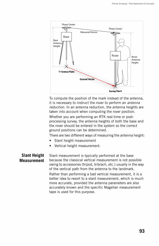
Precise Surveying - Field Applications & Concepts
To compute the position of the mark instead of the antenna, it is necessary to instruct the rover to perform an antenna reduction. In an antenna reduction, the antenna heights are taken into account when computing the rover position.Whether you are performing an RTK real-time or post-processing survey, the antenna heights of both the base and the rover should be entered in the system so the correct ground positions can be determined.There are two different ways of measuring the antenna height:• Slant height measurement• Vertical height measurement.
Slant HeightMeasurement
Slant measurement is typically performed at the base because the classical vertical measurement is not possible owing to accessories (tripod, tribrach, etc.) usually in the way of the vertical path from the antenna to the landmark.Rather than performing a bad vertical measurement, it is a better idea to resort to a slant measurement, which is much more accurate, provided the antenna parameters are also accurately known and the specific Magellan measurement tape is used for this purpose.
Measured Vector
Phase Center
Phase Center
Ground Vector
Reference Point
Survey Point
Base
Rover
Base Antenna Height
Rover Antenna Height
93
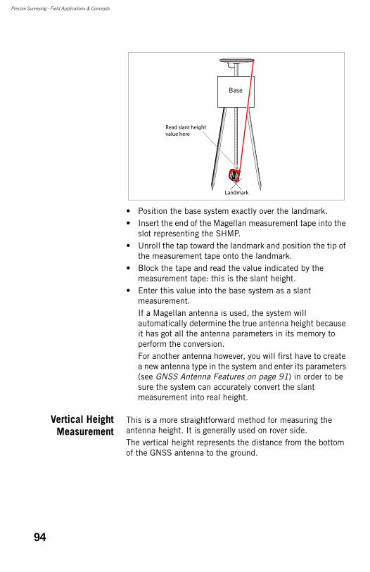
Precise Surveying - Field Applications & Concepts
• Position the base system exactly over the landmark.• Insert the end of the Magellan measurement tape into the
slot representing the SHMP.• Unroll the tap toward the landmark and position the tip of
the measurement tape onto the landmark.• Block the tape and read the value indicated by the
measurement tape: this is the slant height.• Enter this value into the base system as a slant
measurement.If a Magellan antenna is used, the system will automatically determine the true antenna height because it has got all the antenna parameters in its memory to perform the conversion.For another antenna however, you will first have to create a new antenna type in the system and enter its parameters (see GNSS Antenna Features on page 91) in order to be sure the system can accurately convert the slant measurement into real height.
Vertical HeightMeasurement
This is a more straightforward method for measuring the antenna height. It is generally used on rover side.The vertical height represents the distance from the bottom of the GNSS antenna to the ground.
Landmark
Base
Read slant height value here
94
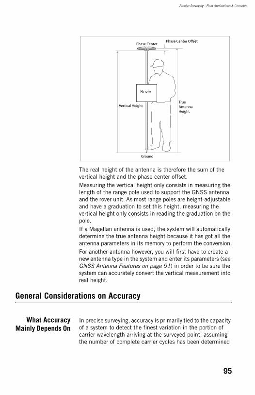
Precise Surveying - Field Applications & Concepts
The real height of the antenna is therefore the sum of the vertical height and the phase center offset.Measuring the vertical height only consists in measuring the length of the range pole used to support the GNSS antenna and the rover unit. As most range poles are height-adjustable and have a graduation to set this height, measuring the vertical height only consists in reading the graduation on the pole.If a Magellan antenna is used, the system will automatically determine the true antenna height because it has got all the antenna parameters in its memory to perform the conversion.For another antenna however, you will first have to create a new antenna type in the system and enter its parameters (see GNSS Antenna Features on page 91) in order to be sure the system can accurately convert the vertical measurement into real height.
General Considerations on Accuracy
What AccuracyMainly Depends On
In precise surveying, accuracy is primarily tied to the capacity of a system to detect the finest variation in the portion of carrier wavelength arriving at the surveyed point, assuming the number of complete carrier cycles has been determined
Phase CenterPhase Center Offset
True Antenna Height
Vertical Height
Rover
Ground
95
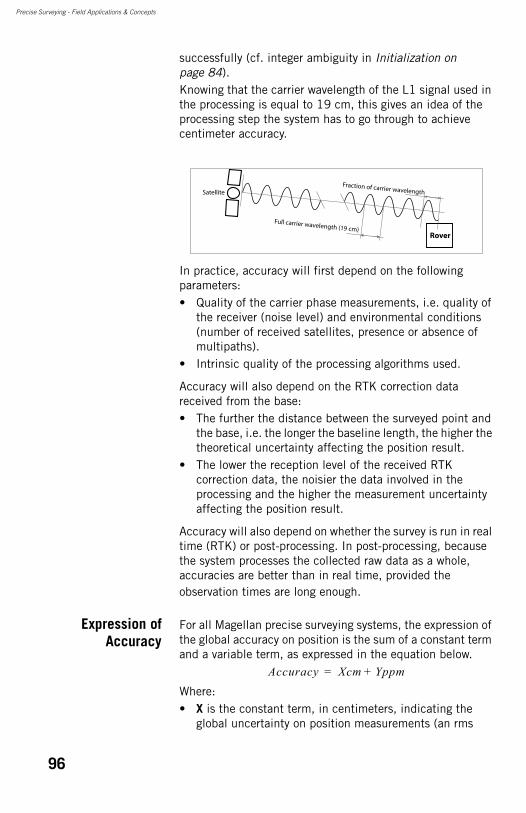
Precise Surveying - Field Applications & Concepts
successfully (cf. integer ambiguity in Initialization on page 84).Knowing that the carrier wavelength of the L1 signal used in the processing is equal to 19 cm, this gives an idea of the processing step the system has to go through to achieve centimeter accuracy.
In practice, accuracy will first depend on the following parameters: • Quality of the carrier phase measurements, i.e. quality of
the receiver (noise level) and environmental conditions (number of received satellites, presence or absence of multipaths).
• Intrinsic quality of the processing algorithms used.
Accuracy will also depend on the RTK correction data received from the base:• The further the distance between the surveyed point and
the base, i.e. the longer the baseline length, the higher the theoretical uncertainty affecting the position result.
• The lower the reception level of the received RTK correction data, the noisier the data involved in the processing and the higher the measurement uncertainty affecting the position result.
Accuracy will also depend on whether the survey is run in real time (RTK) or post-processing. In post-processing, because the system processes the collected raw data as a whole, accuracies are better than in real time, provided the observation times are long enough.
Expression ofAccuracy
For all Magellan precise surveying systems, the expression of the global accuracy on position is the sum of a constant term and a variable term, as expressed in the equation below.
Where:• X is the constant term, in centimeters, indicating the
global uncertainty on position measurements (an rms
Satellite
Full carrier wavelength (19 cm)
Fraction of carrier wavelength
Rover
Accuracy Xcm Yppm+=
96
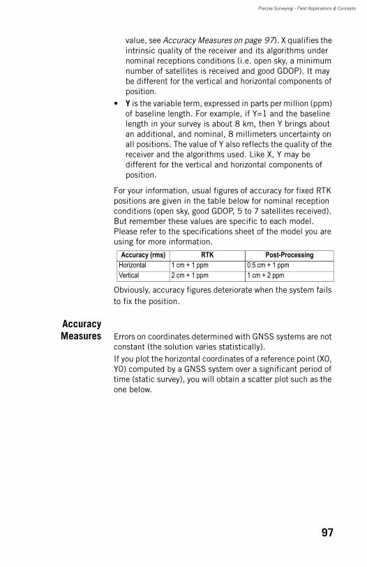
Precise Surveying - Field Applications & Concepts
value, see Accuracy Measures on page 97). X qualifies the intrinsic quality of the receiver and its algorithms under nominal receptions conditions (i.e. open sky, a minimum number of satellites is received and good GDOP). It may be different for the vertical and horizontal components of position.
• Y is the variable term, expressed in parts per million (ppm) of baseline length. For example, if Y=1 and the baseline length in your survey is about 8 km, then Y brings about an additional, and nominal, 8 millimeters uncertainty on all positions. The value of Y also reflects the quality of the receiver and the algorithms used. Like X, Y may be different for the vertical and horizontal components of position.
For your information, usual figures of accuracy for fixed RTK positions are given in the table below for nominal reception conditions (open sky, good GDOP, 5 to 7 satellites received). But remember these values are specific to each model. Please refer to the specifications sheet of the model you are using for more information.
Obviously, accuracy figures deteriorate when the system fails to fix the position.
AccuracyMeasures Errors on coordinates determined with GNSS systems are not
constant (the solution varies statistically).If you plot the horizontal coordinates of a reference point (X0, Y0) computed by a GNSS system over a significant period of time (static survey), you will obtain a scatter plot such as the one below.
Accuracy (rms) RTK Post-ProcessingHorizontal 1 cm + 1 ppm 0.5 cm + 1 ppmVertical 2 cm + 1 ppm 1 cm + 2 ppm
97
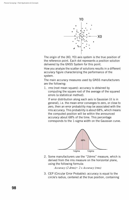
Precise Surveying - Field Applications & Concepts
The origin of the (X0, Y0) axis system is the true position of the reference point. Each dot represents a position solution delivered by the GNSS System for this point.How you analyze the scatter of solutions results in a different accuracy figure characterizing the performance of the system.The main accuracy measures used by GNSS manufacturers are the following:1. rms (root mean square): accuracy is obtained by
computing the square root of the average of the squared errors (a statistical method).If error distribution along each axis is Gaussian (it is in general), i.e. the mean error converges to zero, or close to zero, then an error probability may be associated with the rms accuracy. This probability is about 68%, which means the computed position will be within the announced accuracy about 68% of the time. This percentage corresponds to the 1-sigma width on the Gaussian curve.
2. Some manufacturers use the “2drms” measure, which is derived from the rms measure on the horizontal plane, using the following formula:
3. CEP (Circular Error Probable): accuracy is equal to the circle's radius, centered at the true position, containing
X0
Y0
1sigma
68%
1sigma
Accuracy (2 drms)= 2 x Accuracy (rms)
98

Precise Surveying - Field Applications & Concepts
50% of the points in the horizontal scatter plot (see chart below). This means the computed position will be within the announced accuracy 50% of the time.
Ellipsoidal Height and Elevation
The vertical coordinate measured by GNSS systems is worth an explanation. Behind this coordinate in fact lies the specificity of GNSS systems compared to conventional surveying systems.Basically, all positions delivered by GNSS systems consist of geographic coordinates (latitude, longitude, height) referenced to an ellipsoid, called reference ellipsoid, which is a simple and accurate model to describe the shape and surface of our planet.The reference ellipsoid refers to the WGS84, or better the ITRF00.The center of this reference ellipsoid coincides with the center of the mass of the Earth, which is also the origin point of the Earth-Centered Earth-Fixed (ECEF) X, Y, Z Cartesian coordinate system.As far as horizontal coordinates are concerned, the reference ellipsoid gives full satisfaction. Converting geographic coordinates to any projection system does not raise any particular problem.Things are a bit more complicated though when dealing with vertical coordinates because surveyors need to define very precisely which type of vertical coordinates they wish to measure.The vertical coordinate provided by GNSS systems basically is the height of the surveyed point over the reference ellipsoid. We call it the ellipsoidal height.
X0
CEP
Y0
99
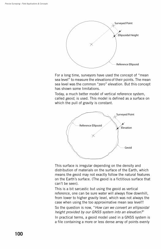
Precise Surveying - Field Applications & Concepts
For a long time, surveyors have used the concept of “mean sea level” to measure the elevations of their points. The mean sea level was the common “zero” elevation. But this concept has shown some limitations.Today, a much better model of vertical reference system, called geoid, is used. This model is defined as a surface on which the pull of gravity is constant.
This surface is irregular depending on the density and distribution of materials on the surface of the Earth, which means the geoid may not exactly follow the natural features on the Earth’s surface. (The geoid is a fictitious surface that can’t be seen).This is a bit sarcastic but using the geoid as vertical reference, one can be sure water will always flow downhill, from lower to higher gravity level, which was not always the case when using the too approximative mean sea level!!So the question is now, “How can we convert an ellipsoidal height provided by our GNSS system into an elevation?”In practical terms, a geoid model used in a GNSS system is a file containing a more or less dense array of points evenly
Ellipsoidal Height
Reference Ellipsoid
Surveyed Point
Reference Ellipsoid
Surveyed Point
Geoid
Elevation
100
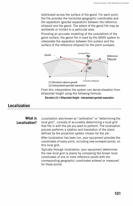
Precise Surveying - Field Applications & Concepts
distributed across the surface of the geoid. For each point, the file provides the horizontal geographic coordinates and the separation (geoidal separation) between the reference ellipsoid and the geoid. The extent of the geoid file may be worldwide or limited to a particular area.Providing an accurate modelling of the undulations of the geoid surface, the geoid file is used by the GNSS system to interpolate the separation between this surface and the surface of the reference ellipsoid for the point surveyed.
From this interpolation the system can derive elevation from ellipsoidal height using the following formula:
Elevation [1] = Ellipsoidal Height - Interpolated geoidal separation
Localization
What isLocalization?
Localization, also known as “calibration” or “determining the local grid”, consists of accurately determining a local grid that fits in with the job you want to perform. The localization process performs a rotation and translation of the plane defined by the projection system chosen for the job.After localization has been run, your equipment provides the coordinates of every point, including new surveyed points, on this local grid.Typically through localization, your equipment determines the new local grid (a plane) by comparing the known local coordinates of one or more reference points with the corresponding geographic coordinates entered or measured for these points.
ReferenceEllipsoid
Surveyed PointGeoid
To center of ellipsoid
[1]
[1]: Elevation (above geoid)[2]: Interpolated geoidal separation
[2]
101
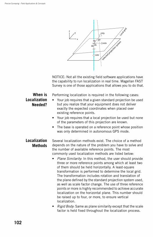
Precise Surveying - Field Applications & Concepts
NOTICE: Not all the existing field software applications have the capability to run localization in real time. Magellan FAST Survey is one of those applications that allows you to do that.
When isLocalization
Needed?
Performing localization is required in the following cases:• Your job requires that a given standard projection be used
but you realize that your equipment does not deliver exactly the expected coordinates when placed over existing reference points.
• Your job requires that a local projection be used but none of the parameters of this projection are known.
• The base is operated on a reference point whose position was only determined in autonomous GPS mode.
LocalizationMethods
Several localization methods exist. The choice of a method depends on the nature of the problem you have to solve and the number of available reference points. The most commonly used localization methods are listed below:• Plane Similarity: In this method, the user should provide
three or more reference points among which at least two of them should be held horizontally. A least-square transformation is performed to determine the local grid. The transformation includes rotation and translation of the plane defined by the standard projection system used, as well as scale factor change. The use of three reference points or more is highly recommended to achieve accurate localization on the horizontal plane. This number should be raised up to four, or more, to ensure vertical localization.
• Rigid Body: Same as plane similarity except that the scale factor is held fixed throughout the localization process.
x
yz
Loca
l grid
Selected p
rojectio
n syste
mdy
dxrotx
roty
rotz
dz
102
Precise Surveying - Field Applications & Concepts
• Helmert: With this method, the user provides the seven parameters modifying the projection system currently used in the job. These parameters (dX, dY, dZ, rot X, rot Y, rot Z and scale factor) may be the result of a multi-point localization performed earlier.
• One-Point Azimuth: This method is used when only one reference point is available to determine the local grid. In this case, the user should specify the orientation of the North direction of the local grid (geographic or true).A typical application of this method is to use the point where the base is installed at the origin (0, 0, 0), or on a singular point (e.g. 100, 1000, 0) of the local grid. In this case, the geographic coordinates of the base position may feature only several meter accuracy since the surveyor is only interested in collecting local coordinates for the job. It will therefore be the surveyor’s responsibility to make sure the geographic coordinates of the base (typically determined through the autonomous GPS mode) can be fed into the localization process.
A geoid model can be included in the localization process. In this case, all elevations provided for the reference points used should be orthometric instead of ellipsoidal.
TypicalInstructions to
Complete aLocalization
Process
Localization based on the use of reference points is typically achieved through the following steps:1. Make sure the right projection system is selected in your
job. What does that mean? Here are the two cases to consider:• Some reference points that you will hold horizontally or
vertically fixed in the localization process may have their coordinates expressed in a known projection system. We recommend you select this projection as the job’s initial projection system.
• If the local coordinates of your reference points do not refer to any known projection system, then we recommend you choose a projection system that is standard in your working area.
2. Enter the local coordinates of the first reference point.3. Enter the latitude, longitude and ellipsoidal height of the
first reference point.4. Set horizontal or/and vertical control for the first reference
point. This means requiring that the local grid pass through respectively the horizontal or/and vertical position of the point.
103

Precise Surveying - Field Applications & Concepts
5. Resume the previous three steps until all the reference points have been defined.
6. Run the localization process and make sure the local grid is now the new projection system used in the job.
104
Chapter 7. RTK Implementation
Data Link
In an RTK surveying system, the data link is used to transfer RTK correction data from the base to the rover.The data link may be one of the following two types:• Standalone: You will have full control over the generation
and transmission of RTK correction data (Magellan equipment used in base/rover configuration).
• Network-based: You will be resorting to a third-party, network-based provider for the generation and delivery of RTK correction data (Magellan equipment used in rover-only configuration)
This section introduces the two basic transmission means available in Magellan surveying systems for setting up this data link:• Radio (standalone)• GSM.
For GSM, this section describes the different operating modes available:• CSD (standalone)• NTRIP (network-based)• Direct IP (network-based).
Key Terms andExpressions
Age of Corrections: The age of corrections is measured as the time elapsed between the time corrections are generated in a base and the time when they are effectively used to yield an RTK position in a rover. Generally speaking, the quality of corrections decreases as their age increases.CSD: Circuit Switched Data. is the original form of data transmission developed for the time division multiple access (TDMA)-based mobile phone systems like GSM.Direct IP: (IP=Internet Protocol). A way of acquiring base data from the Internet via a network connection.
105
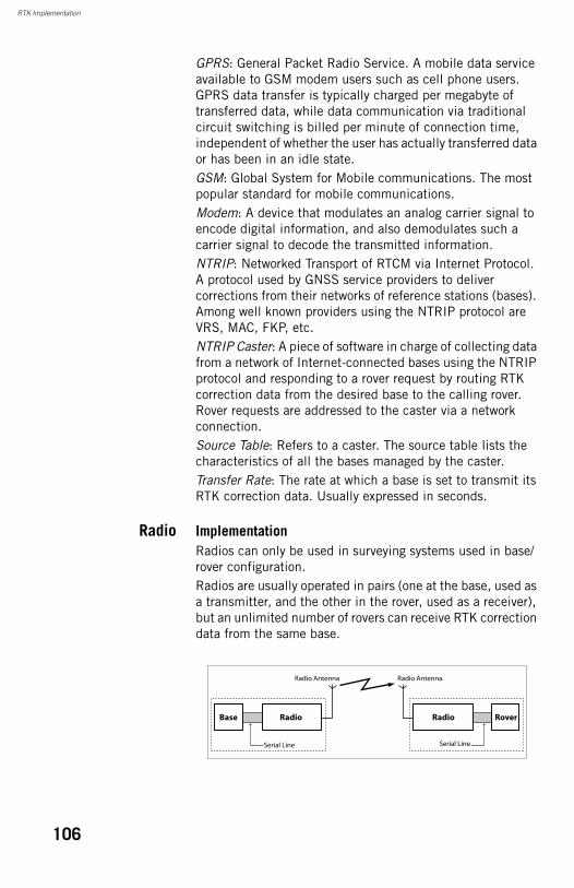
RTK Implementation
GPRS: General Packet Radio Service. A mobile data service available to GSM modem users such as cell phone users. GPRS data transfer is typically charged per megabyte of transferred data, while data communication via traditional circuit switching is billed per minute of connection time, independent of whether the user has actually transferred data or has been in an idle state.GSM: Global System for Mobile communications. The most popular standard for mobile communications.Modem: A device that modulates an analog carrier signal to encode digital information, and also demodulates such a carrier signal to decode the transmitted information.NTRIP: Networked Transport of RTCM via Internet Protocol. A protocol used by GNSS service providers to deliver corrections from their networks of reference stations (bases). Among well known providers using the NTRIP protocol are VRS, MAC, FKP, etc.NTRIP Caster: A piece of software in charge of collecting data from a network of Internet-connected bases using the NTRIP protocol and responding to a rover request by routing RTK correction data from the desired base to the calling rover. Rover requests are addressed to the caster via a network connection.Source Table: Refers to a caster. The source table lists the characteristics of all the bases managed by the caster.Transfer Rate: The rate at which a base is set to transmit its RTK correction data. Usually expressed in seconds.
Radio ImplementationRadios can only be used in surveying systems used in base/rover configuration.Radios are usually operated in pairs (one at the base, used as a transmitter, and the other in the rover, used as a receiver), but an unlimited number of rovers can receive RTK correction data from the same base.
Base
Serial Line
Radio Antenna Radio Antenna
RadioRadio
Serial Line
Rover
106
RTK Implementation
An important factor is the radio range. It should be equal to or greater than the maximum baseline length you need to survey.
Internal vs. External RadiosDepending on the model of Magellan receiver used, the pair of radios can be:• Incorporated into the Magellan receiver. Only the radio
antenna is visible from outside. The modem is connected to the system via a serial line.
• External to the Magellan receiver and connected to it via a power/serial data cable.
License-Free vs. Non License-Free RadiosIn almost all countries, radio systems are submitted to laws regulating their use. Regulations are more especially about transmission power, frequency band and channel bandwidth. They may differ from one country to the other.In most countries however, radios used under a certain level of radiated power in dedicated frequency bands do not require a certification (or license) to be operated freely. For this reason, Magellan offers two types of radios:• License-free, low-power radios (short range) (available for
some models of Magellan receivers)(not available with ProMark 500).
• Non license-free, medium-power radios (longer range). For this type of equipment, Magellan will help you get the certification required for use of the radio in your country. But remember the right to operate a radio is your responsibility.
FeaturesThe main features of a radio are the following:• UHF Frequency band: Range of UHF frequencies on
which the radio transmits or receives data (license-free radios operate in the 850-930 MHz band, other radios in the 410-470 MHz band).
• Channel spacing or channel bandwidth: Space occupied by one channel (in kHz).
• Radiated power: Transmission power, in watts (W) radiated by the radio used at the base.
• Channel number: Corresponds to a specific carrier frequency within the band. In theory, the number of available channels is equal to the ratio between the whole frequency band and the one-channel bandwidth.
107
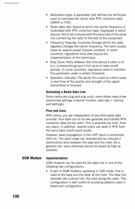
RTK Implementation
• Modulation type: A parameter that defines the technique used to modulate the carrier with RTK correction data (GMSK or FSK)
• Radio data rate: Speed at which the carrier frequency is modulated with RTK correction data. Expressed in kbits/second. Not to be confused with the baud rate of the serial line connecting the radio to the rest of the equipment.
• Frequency hopping: A process through which the radio regularly changes the carrier frequency. The radio usually loops on several preset channel numbers. In some countries, regulations exist that require the implementation of this technique.
• Duty Cycle: Ratio between the time period a radio is on (i.e. is transmitting) and a full cycle of radio on/off periods. In some countries, regulations exist to maintain this parameter under a certain threshold.
• Operation indicator: The ability for a radio to inform users in real time of the quality and strength of the signal transmitted or received.
Activating a Radio Data LinkSome radios are plug-and-play units, some others need a few preliminary settings (channel number, data rate + internal port settings).
Pros and ConsWith radios, you are independent of any third-party data provider. Your base can on its own generate and transfer RTK correction data via the radio. This is possible any time, from any place. In addition, several rovers can work in RTK from the same base (multi-point mode).However, wave propagation in the UHF band is sometimes difficult. The radio range can dramatically be reduced if obstructions exist between the base and the rover. As a general rule, radio antennas should be raised as high as possible.
GSM Modem ImplementationGSM modems can be used for the data link in one of the following two configurations:• A pair of GSM modems operating in CSD mode. One is
used at the base and the other at the rover. The data link operates like a phone link, the rover being the caller. This configuration is well suited to surveying systems used in base/rover configuration.
108
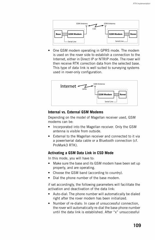
RTK Implementation
• One GSM modem operating in GPRS mode. The modem is used on the rover side to establish a connection to the Internet, either in Direct IP or NTRIP mode. The rover will then receive RTK correction data from the selected base. This type of data link is well suited to surveying systems used in rover-only configuration.
Internal vs. External GSM ModemsDepending on the model of Magellan receiver used, GSM modems can be:• Incorporated into the Magellan receiver. Only the GSM
antenna is visible from outside.• External to the Magellan receiver and connected to it via
a power/serial data cable or a Bluetooth connection (cf. ProMark3 RTK).
Activating a GSM Data Link in CSD ModeIn this mode, you will have to:• Make sure the base and its GSM modem have been set up
properly, and are operating.• Choose the GSM band (according to country).• Dial the phone number of the base modem.
if set accordingly, the following parameters will facilitate the activation and deactivation of the data link:• Auto-dial: The phone number will automatically be dialed
right after the rover modem has been initialized.• Number of re-dials: In case of unsuccessful connection,
the rover will automatically re-dial the base phone number until the data link is established. After “x” unsuccessful
Base
Serial Line
GSM Antenna GSM Antenna
GSM ModemGSM Modem
Serial Line
Rover
CSD
GSM Antenna
GSM Modem
Serial Line
Rover
InternetGPRS
109
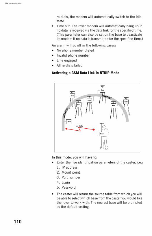
RTK Implementation
re-dials, the modem will automatically switch to the idle state.
• Time out: The rover modem will automatically hang up if no data is received via the data link for the specified time. (This parameter can also be set on the base to deactivate its modem if no data is transmitted for the specified time.)
An alarm will go off in the following cases:• No phone number dialed• Invalid phone number• Line engaged• All re-dials failed.
Activating a GSM Data Link in NTRIP Mode
In this mode, you will have to:• Enter the five identification parameters of the caster, i.e.:
1. IP address2. Mount point3. Port number4. Login5. Password
• The caster will return the source table from which you will be able to select which base from the caster you would like the rover to work with. The nearest base will be prompted as the default setting.
Base
Base
Base
Rover
Inte
rnet
Base
BaseBase
Caster
GPRS
Internet
110
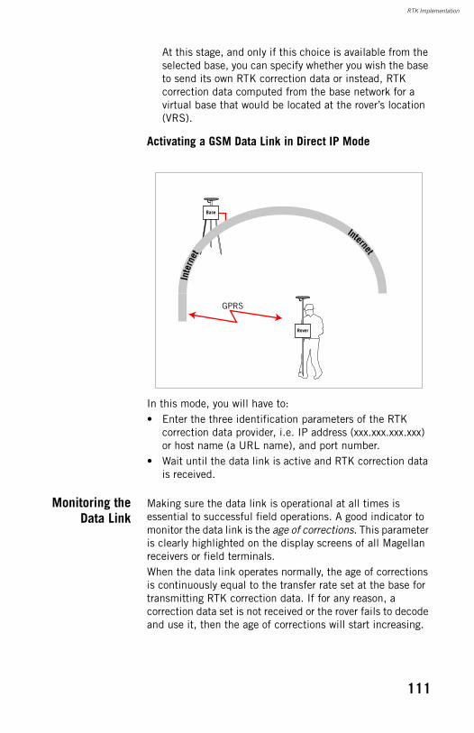
RTK Implementation
At this stage, and only if this choice is available from the selected base, you can specify whether you wish the base to send its own RTK correction data or instead, RTK correction data computed from the base network for a virtual base that would be located at the rover’s location (VRS).
Activating a GSM Data Link in Direct IP Mode
In this mode, you will have to:• Enter the three identification parameters of the RTK
correction data provider, i.e. IP address (xxx.xxx.xxx.xxx) or host name (a URL name), and port number.
• Wait until the data link is active and RTK correction data is received.
Monitoring theData Link
Making sure the data link is operational at all times is essential to successful field operations. A good indicator to monitor the data link is the age of corrections. This parameter is clearly highlighted on the display screens of all Magellan receivers or field terminals.When the data link operates normally, the age of corrections is continuously equal to the transfer rate set at the base for transmitting RTK correction data. If for any reason, a correction data set is not received or the rover fails to decode and use it, then the age of corrections will start increasing.
Base
Rover
Inte
rnet
GPRS
Internet
111

RTK Implementation
If the increase is only temporary, then you should not care too much about the data link as long as the rover continues to provide “fixed” positions.But if the age of corrections keeps on increasing, then the problem is more serious as it can only result in a rover losing the “fixed” status for all the positions it delivers. In this case, you should figure out why the data link fails and take the necessary steps to bring it back to work.So the recommendation is to constantly keep an eye on the age of corrections as you progress in your field operations.In some of the available Magellan receivers, you can set a parameter, called “maximum age of corrections” defining an upper limit for the age of corrections. If for any reason the age of corrections reaches this limit, a warning message will alert you. There is no such possibility in the ProMark 500.
112
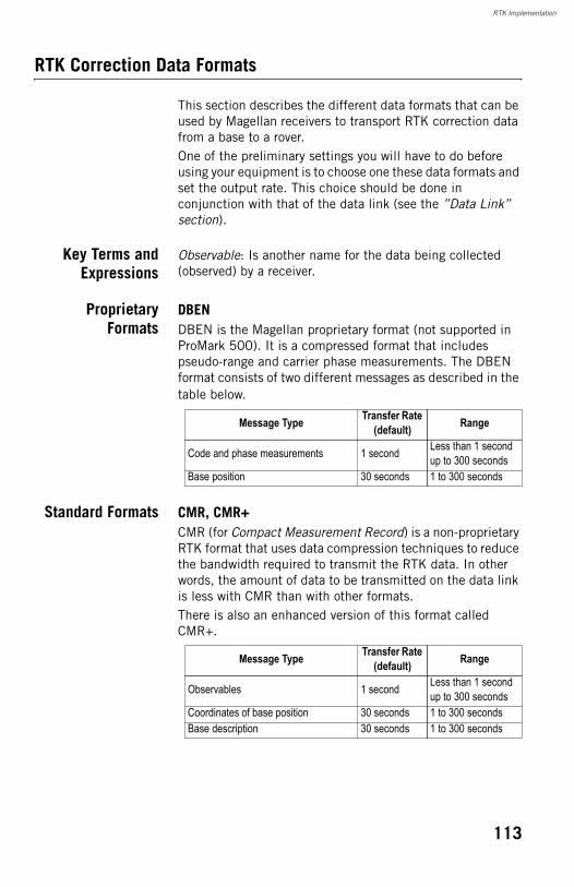
RTK Implementation
RTK Correction Data Formats
This section describes the different data formats that can be used by Magellan receivers to transport RTK correction data from a base to a rover.One of the preliminary settings you will have to do before using your equipment is to choose one these data formats and set the output rate. This choice should be done in conjunction with that of the data link (see the ”Data Link” section).
Key Terms andExpressions
Observable: Is another name for the data being collected (observed) by a receiver.
ProprietaryFormats
DBENDBEN is the Magellan proprietary format (not supported in ProMark 500). It is a compressed format that includes pseudo-range and carrier phase measurements. The DBEN format consists of two different messages as described in the table below.
Standard Formats CMR, CMR+CMR (for Compact Measurement Record) is a non-proprietary RTK format that uses data compression techniques to reduce the bandwidth required to transmit the RTK data. In other words, the amount of data to be transmitted on the data link is less with CMR than with other formats.There is also an enhanced version of this format called CMR+.
Message Type Transfer Rate (default) Range
Code and phase measurements 1 second Less than 1 second up to 300 seconds
Base position 30 seconds 1 to 300 seconds
Message Type Transfer Rate (default) Range
Observables 1 second Less than 1 second up to 300 seconds
Coordinates of base position 30 seconds 1 to 300 secondsBase description 30 seconds 1 to 300 seconds
113
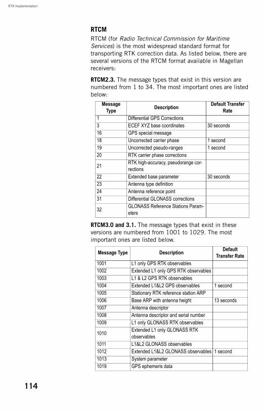
RTK Implementation
RTCMRTCM (for Radio Technical Commission for Maritime Services) is the most widespread standard format for transporting RTK correction data. As listed below, there are several versions of the RTCM format available in Magellan receivers:
RTCM2.3. The message types that exist in this version are numbered from 1 to 34. The most important ones are listed below:
RTCM3.0 and 3.1. The message types that exist in these versions are numbered from 1001 to 1029. The most important ones are listed below.
Message Type Description Default Transfer
Rate1 Differential GPS Corrections3 ECEF XYZ base coordinates 30 seconds16 GPS special message18 Uncorrected carrier phase 1 second19 Uncorrected pseudo-ranges 1 second20 RTK carrier phase corrections
21 RTK high-accuracy, pseudorange cor-rections
22 Extended base parameter 30 seconds23 Antenna type definition24 Antenna reference point31 Differential GLONASS corrections
32 GLONASS Reference Stations Param-eters
Message Type Description Default Transfer Rate
1001 L1 only GPS RTK observables1002 Extended L1 only GPS RTK observables1003 L1 & L2 GPS RTK observables1004 Extended L1&L2 GPS observables 1 second1005 Stationary RTK reference station ARP1006 Base ARP with antenna height 13 seconds1007 Antenna descriptor1008 Antenna descriptor and serial number1009 L1 only GLONASS RTK observables
1010 Extended L1 only GLONASS RTK observables
1011 L1&L2 GLONASS observables1012 Extended L1&L2 GLONASS observables 1 second1013 System parameter1019 GPS ephemeris data
114

RTK Implementation
1020 GLONASS ephemeris data1029 Unicode text string1033 Receiver and antenna descriptors 31 seconds
Message Type Description Default Transfer Rate
115
RTK Implementation
RTK Position Output
RTK PositionOutput Mode
DefinitionSome field applications require the fastest possible position output rate whereas some others can do with a slower output rate provided the position accuracy is maximum.Setting the RTK position output mode allows you to choose the position output that is right for your application.Magellan receivers offer two different RTK position output modes:• Time-tagged RTK mode, also called “Synchronized RTK”
mode.• Fast RTK mode.
Key Terms and ExpressionsLatency: Delay between the time (t0) for which an RTK position is requested and the time (t1) when the rover starts delivering that position. More precisely, t1 represents the time when the rover outputs the position data’s first character. Caution! At time t1, the rover will start delivering the position it occupied at time t0, and not the position it is occupying at time t1. This is true for the two output modes presented in this section.Epoch: Relevant to a particular time at which a full set of RTK correction data is generated by the base. As this time of data availability is cyclical, each occurrence of this particular time is called an epoch.Extrapolation: A process through which the rover can continue to compute accurate positions by extrapolating the RTK correction data last received from the base. Generally speaking, in an extrapolation process, a system tries to predict with the best possible accuracy the most likely value of a quantity in a very near future.
116
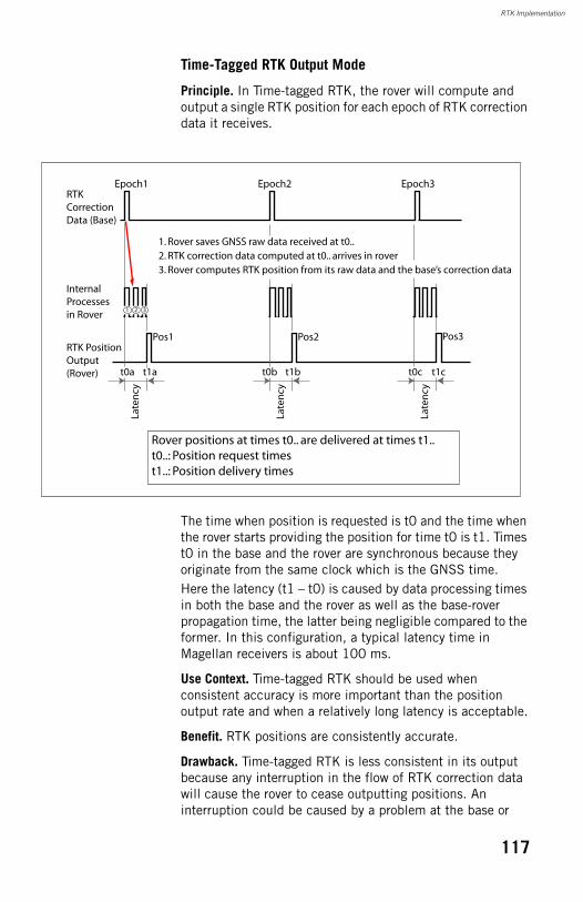
RTK Implementation
Time-Tagged RTK Output Mode
Principle. In Time-tagged RTK, the rover will compute and output a single RTK position for each epoch of RTK correction data it receives.
The time when position is requested is t0 and the time when the rover starts providing the position for time t0 is t1. Times t0 in the base and the rover are synchronous because they originate from the same clock which is the GNSS time.Here the latency (t1 – t0) is caused by data processing times in both the base and the rover as well as the base-rover propagation time, the latter being negligible compared to the former. In this configuration, a typical latency time in Magellan receivers is about 100 ms.
Use Context. Time-tagged RTK should be used when consistent accuracy is more important than the position output rate and when a relatively long latency is acceptable.
Benefit. RTK positions are consistently accurate.
Drawback. Time-tagged RTK is less consistent in its output because any interruption in the flow of RTK correction data will cause the rover to cease outputting positions. An interruption could be caused by a problem at the base or
Late
ncy
Late
ncy
Late
ncy
Epoch1 Epoch2 Epoch3
Pos1
RTK Correction Data (Base)
RTK Position Output (Rover)
Internal Processes in Rover
t0a t1a t0b t1b t0c t1c
Pos2 Pos3
Rover positions at times t0.. are delivered at times t1..t0..: Position request timest1..: Position delivery times
2. RTK correction data computed at t0.. arrives in rover3. Rover computes RTK position from its raw data and the base’s correction data
1. Rover saves GNSS raw data received at t0..
2 31
117
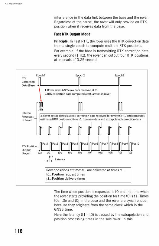
RTK Implementation
interference in the data link between the base and the rover. Regardless of the cause, the rover will only provide an RTK position when it receives data from the base.
Fast RTK Output Mode
Principle. In Fast RTK, the rover uses the RTK correction data from a single epoch to compute multiple RTK positions.For example, if the base is transmitting RTK correction data every second (1 Hz), the rover can output four RTK positions at intervals of 0.25 second.
The time when position is requested is t0 and the time when the rover starts providing the position for time t0 is t1. Times t0a, t0e and t0j in the base and the rover are synchronous because they originate from the same clock which is the GNSS time.Here the latency (t1 – t0) is caused by the extrapolation and position processing times in the sole rover. In this
Epoch1 Epoch2 Epoch3RTK Correction Data (Base)
RTK Position Output (Rover)
Internal Processes in Rover
Latency
Rover positions at times t0.. are delivered at times t1..t0..: Position request timest1..: Position delivery times
2. RTK correction data computed at t0.. arrives in rover1. Rover saves GNSS raw data received at t0..
Pos1 Pos2 Pos3 Pos4 Pos5 Pos6 Pos7 Pos8 Pos9 Pos10
t0a t0bt1b
t0c t0d t0e t0f t0g t0h t0i t0j
3. Rover extrapolates last RTK correction data received for time t0(x-1).. and computes estimated RTK position at time t0.. from raw data and extrapolated correction data
21
118
RTK Implementation
configuration, a typical latency time in Magellan receivers is 15 ms.
Use Context. Fast RTK should be used when consistent and high-rate position updates are required, such as in machine control or field operator guidance, and when consistent position accuracy is not the highest priority.
Benefits. The position output rate is less sensitive to the rate at which the rover receives RTK correction data.The latency is shorter than in time-tagged mode thanks to the extrapolation process.The rover will continue to compute positions even if there is a minor interruption in the RTK correction data. Under good conditions, centimeter-level accuracy can be maintained in the rover even if no RTK correction data is received for several seconds.
Drawback. Accuracy is slightly degraded with extrapolated solutions because the noise level on these solutions is higher.
Insensitivity of the Fast RTK Mode to Missing Base EpochsThe diagram below shows how the two output modes react when an epoch of RTK correction data is missing.
119
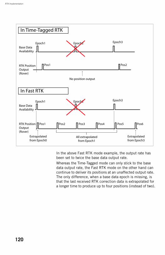
RTK Implementation
In the above Fast RTK mode example, the output rate has been set to twice the base data output rate.Whereas the Time-Tagged mode can only stick to the base data output rate, the Fast RTK mode on the other hand can continue to deliver its positions at an unaffected output rate. The only difference, when a base data epoch is missing, is that the last received RTK correction data is extrapolated for a longer time to produce up to four positions (instead of two).
In Time-Tagged RTK
In Fast RTK
Epoch1 Epoch2
Pos1
Pos1
Pos2 Pos3
Pos2
Pos4 Pos5 Pos6
Base Data Availability
RTK Position Output (Rover)
Base Data Availability
RTK Position Output (Rover)
Epoch3
Epoch1 Epoch2 Epoch3
All extrapolatedfrom Epoch1
Extrapolatedfrom Epoch3
No position output
Extrapolatedfrom Epoch0
120

RTK Implementation
RTK PositionOutput Rate
In Time-tagged RTK mode, clearly the rover’s position output rate is equal to the RTK correction data output rate set at the base. It will also depend on the installed firmware options, if applicable to the Magellan equipment used.In Fast RTK mode, the rover’s position output rate can be a multiple of the RTK correction data output rate. It is controlled by a specific user-settable parameter and will also depend on the installed firmware options, if applicable to the Magellan equipment used.
121

RTK Implementation
122
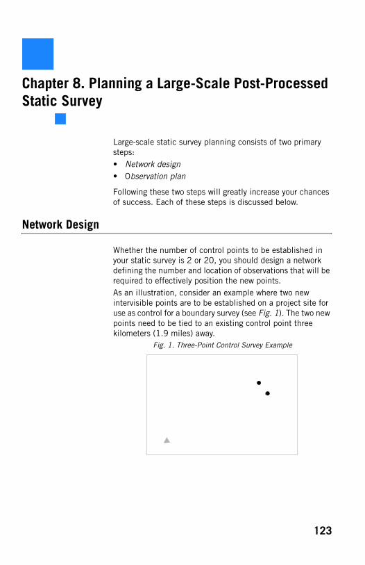
Chapter 8. Planning a Large-Scale Post-Processed Static Survey
Large-scale static survey planning consists of two primary steps:• Network design• Observation plan
Following these two steps will greatly increase your chances of success. Each of these steps is discussed below.
Network Design
Whether the number of control points to be established in your static survey is 2 or 20, you should design a network defining the number and location of observations that will be required to effectively position the new points. As an illustration, consider an example where two new intervisible points are to be established on a project site for use as control for a boundary survey (see Fig. 1). The two new points need to be tied to an existing control point three kilometers (1.9 miles) away.
Fig. 1. Three-Point Control Survey Example
123
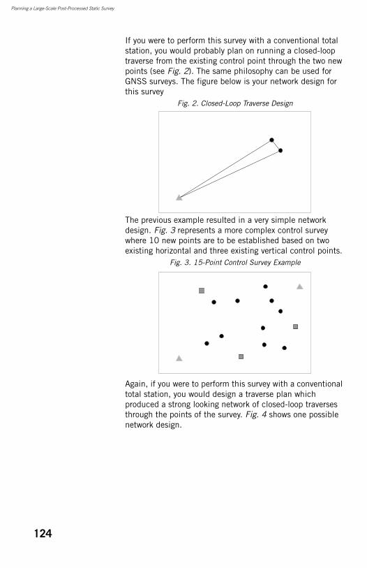
Planning a Large-Scale Post-Processed Static Survey
If you were to perform this survey with a conventional total station, you would probably plan on running a closed-loop traverse from the existing control point through the two new points (see Fig. 2). The same philosophy can be used for GNSS surveys. The figure below is your network design for this survey
Fig. 2. Closed-Loop Traverse Design
The previous example resulted in a very simple network design. Fig. 3 represents a more complex control survey where 10 new points are to be established based on two existing horizontal and three existing vertical control points.
Fig. 3. 15-Point Control Survey Example
Again, if you were to perform this survey with a conventional total station, you would design a traverse plan which produced a strong looking network of closed-loop traverses through the points of the survey. Fig. 4 shows one possible network design.
124
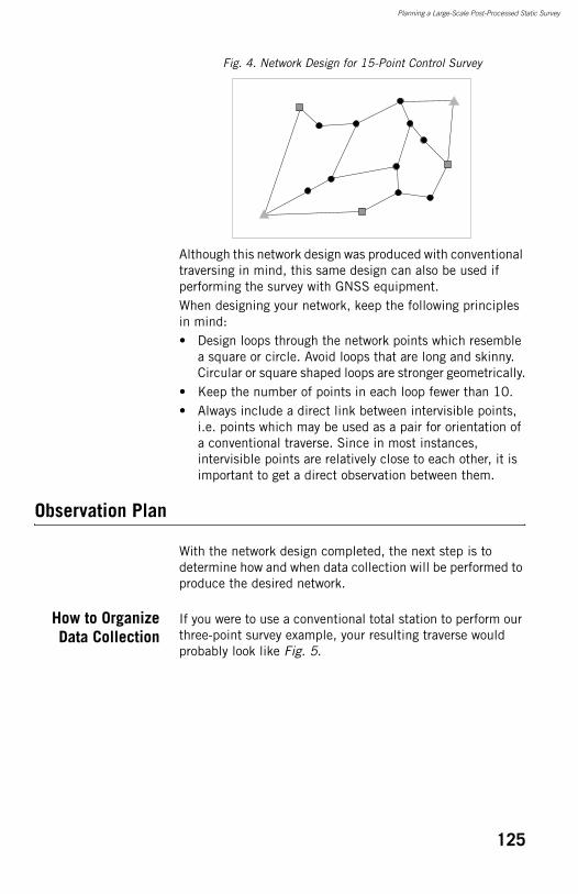
Planning a Large-Scale Post-Processed Static Survey
Fig. 4. Network Design for 15-Point Control Survey
Although this network design was produced with conventional traversing in mind, this same design can also be used if performing the survey with GNSS equipment.When designing your network, keep the following principles in mind:• Design loops through the network points which resemble
a square or circle. Avoid loops that are long and skinny. Circular or square shaped loops are stronger geometrically.
• Keep the number of points in each loop fewer than 10.• Always include a direct link between intervisible points,
i.e. points which may be used as a pair for orientation of a conventional traverse. Since in most instances, intervisible points are relatively close to each other, it is important to get a direct observation between them.
Observation Plan
With the network design completed, the next step is to determine how and when data collection will be performed to produce the desired network.
How to OrganizeData Collection
If you were to use a conventional total station to perform our three-point survey example, your resulting traverse would probably look like Fig. 5.
125
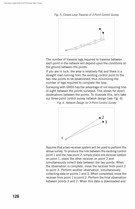
Planning a Large-Scale Post-Processed Static Survey
Fig. 5. Closed-Loop Traverse of 3-Point Control Survey
The number of traverse legs required to traverse between each point in the network will depend upon the conditions on the ground between the points.If you are in luck, the area is relatively flat and there is a straight road running from the existing control point to the two new points to be established, thus minimizing the number of legs required to complete the loop. Surveying with GNSS has the advantage of not requiring line-of-sight between the points surveyed. This allows for direct observations between the points. To illustrate this, let’s take our three-point control survey network design (see Fig. 6).
Fig. 6. Network Design for 3-Point Control Survey
Assume that a two-receiver system will be used to perform the above survey. To produce the link between the existing control point 1 and the new point 2, simply place one receiver system on point 1, place the other receiver on point 2 and simultaneously collect data between the two points. When the observation is complete, move the receiver from point 2 to point 3. Perform another observation, simultaneously collecting data on points 1 and 3. When completed, move the receiver from point 1 to point 2. Perform the final observation between points 3 and 2. When this data is downloaded and
1
23
126
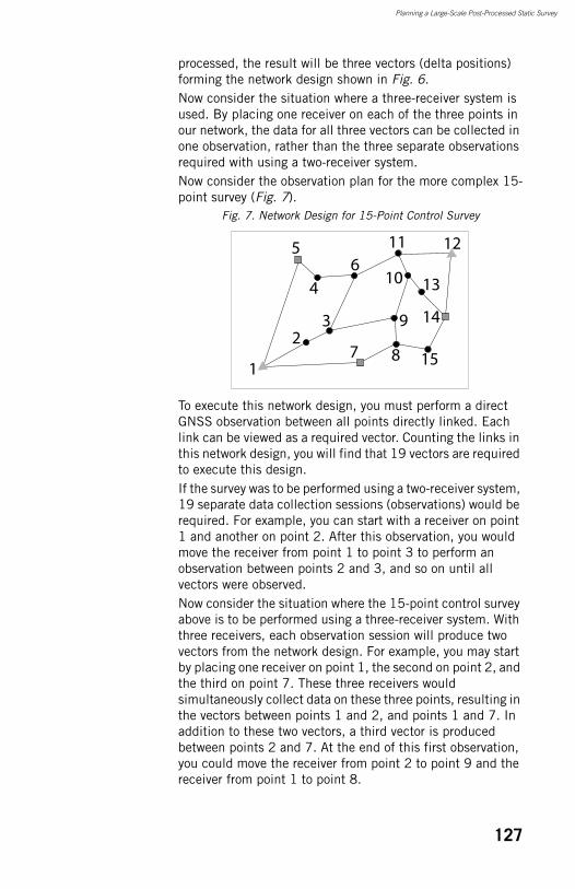
Planning a Large-Scale Post-Processed Static Survey
processed, the result will be three vectors (delta positions) forming the network design shown in Fig. 6.Now consider the situation where a three-receiver system is used. By placing one receiver on each of the three points in our network, the data for all three vectors can be collected in one observation, rather than the three separate observations required with using a two-receiver system.Now consider the observation plan for the more complex 15-point survey (Fig. 7).
Fig. 7. Network Design for 15-Point Control Survey
To execute this network design, you must perform a direct GNSS observation between all points directly linked. Each link can be viewed as a required vector. Counting the links in this network design, you will find that 19 vectors are required to execute this design.If the survey was to be performed using a two-receiver system, 19 separate data collection sessions (observations) would be required. For example, you can start with a receiver on point 1 and another on point 2. After this observation, you would move the receiver from point 1 to point 3 to perform an observation between points 2 and 3, and so on until all vectors were observed.Now consider the situation where the 15-point control survey above is to be performed using a three-receiver system. With three receivers, each observation session will produce two vectors from the network design. For example, you may start by placing one receiver on point 1, the second on point 2, and the third on point 7. These three receivers would simultaneously collect data on these three points, resulting in the vectors between points 1 and 2, and points 1 and 7. In addition to these two vectors, a third vector is produced between points 2 and 7. At the end of this first observation, you could move the receiver from point 2 to point 9 and the receiver from point 1 to point 8.
1
23
4
56
7 8
9
10
11 12
13
14
15
127
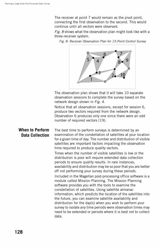
Planning a Large-Scale Post-Processed Static Survey
The receiver at point 7 would remain as the pivot point, connecting the first observation to the second. This would continue until all vectors were observed.Fig. 8 shows what the observation plan might look like with a three-receiver system.
Fig. 8. Receiver Observation Plan for 15-Point Control Survey
The observation plan shows that it will take 10 separate observation sessions to complete the survey based on the network design shown in Fig. 4.Notice that all observation sessions, except for session 6, produce two vectors required from the network design. Observation 6 produces only one since there were an odd number of required vectors (19).
When to PerformData Collection
The best time to perform surveys is determined by an examination of the constellation of satellites at your location for a given time of day. The number and distribution of visible satellites are important factors impacting the observation time required to produce quality vectors.Times when the number of visible satellites is low or the distribution is poor will require extended data collection periods to ensure quality results. In rare instances, availability and distribution may be so poor that you are better off not performing your survey during these periods.Included in the Magellan post-processing office software is a module called Mission Planning. The Mission Planning software provides you with the tools to examine the constellation of satellites. Using satellite almanac information, which predicts the location of the satellites into the future, you can examine satellite availability and distribution for the day(s) when you wish to perform your survey to isolate any time periods were observation times may need to be extended or periods where it is best not to collect data.
123
456 7
98
1010
128

Planning a Large-Scale Post-Processed Static Survey
You provide the software with your current location and the date when you wish to perform your survey. The software then provides you with multiple ways of examining the satellite constellation at your location for the given time. Pay particular attention to satellite availability (number of satellites in view) and the satellite distribution.To assist in analyzing the quality of satellite distribution, Dilution of Precision (DOP) values are presented. DOP is a quality analysis value for satellite distribution. The most popular DOP value is PDOP, which stands for Position Dilution of Precision. The PDOP value estimates the impact on the precision of your observations due to satellite geometry. The smaller the PDOP value the better the satellite distribution (geometry) and therefore the better the precision of your observations.
129

Planning a Large-Scale Post-Processed Static Survey
130
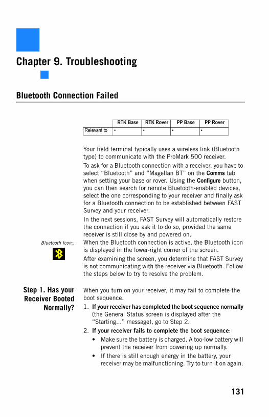
Chapter 9. Troubleshooting
Bluetooth Connection Failed
Your field terminal typically uses a wireless link (Bluetooth type) to communicate with the ProMark 500 receiver.To ask for a Bluetooth connection with a receiver, you have to select “Bluetooth” and “Magellan BT” on the Comms tab when setting your base or rover. Using the Configure button, you can then search for remote Bluetooth-enabled devices, select the one corresponding to your receiver and finally ask for a Bluetooth connection to be established between FAST Survey and your receiver.In the next sessions, FAST Survey will automatically restore the connection if you ask it to do so, provided the same receiver is still close by and powered on.
Bluetooth Icon:: When the Bluetooth connection is active, the Bluetooth icon is displayed in the lower-right corner of the screen.After examining the screen, you determine that FAST Survey is not communicating with the receiver via Bluetooth. Follow the steps below to try to resolve the problem.
Step 1. Has yourReceiver Booted
Normally?
When you turn on your receiver, it may fail to complete the boot sequence. 1. If your receiver has completed the boot sequence normally
(the General Status screen is displayed after the “Starting...” message), go to Step 2.
2. If your receiver fails to complete the boot sequence:• Make sure the battery is charged. A too-low battery will
prevent the receiver from powering up normally.• If there is still enough energy in the battery, your
receiver may be malfunctioning. Try to turn it on again.
RTK Base RTK Rover PP Base PP RoverRelevant to • • • •
131
Troubleshooting
In case of a new failure, call your local dealer or email Magellan technical support for assistance.
Step 2.Does FASTSurvey Ask for a
BluetoothConnection?
When using FAST Survey for the first time, you will need to run a search phase to list the Bluetooth devices present in the vicinity. After opening a job in FAST Survey, the software will prompt you to re-activate the connection with the last receiver used.1. If no receiver is detected the first time you use FAST
Survey, go to Step 3.2. If FAST Survey fails to restore the connection to the last
receiver used, make sure the nearby receiver is the expected one (check its Bluetooth identifier on the Receiver Identification screen). The Bluetooth connection will fail if it’s not the right receiver.
Step 3. Is theReceiver CloseEnough to You?
FAST Survey was unable to detect the receiver. Do the following to resolve the problem.1. Move the field terminal closer to the receiver (1 meter
typical) and resume the search using the Find Receiver button in the Bluetooth Devices window. If after several attempts, no receiver is detected, then either the field terminal or the ProMark 500 has a faulty Bluetooth device.
2. You may try to isolate the problem by turning on another ProMark 500 receiver and resuming the search phase. If it’s successful, then it means the first ProMark 500 is malfunctioning. Call your local dealer or email Magellan technical support for assistance. Conversely, you may try another field terminal to see if the Bluetooth problem is in the first field terminal.
Receiver is Not Tracking Satellites
Step 1. Has theReceiver Been
Powered Up?
To determine if the receiver is powered up, examine the power LED on the front panel of the receiver. If the LED is on, the receiver is on.1. If the receiver is not powered up, turn on the receiver by
pressing and holding the power key on the front panel. The button must be held for a few seconds since there is a
RTK Base RTK Rover PP Base PP RoverRelevant to • • • •
132
Troubleshooting
delay in power on. You will see the power LED turn on and the display will show the Magellan logo followed by the message “Starting...”.
2. If the receiver does not power up, check the power source. The receiver supports both internal (battery) and external power sources.If using the internal power source, make sure the internal battery has been fully charged before it was inserted in the receiver. A too low battery will prevent the receiver from powering up.If using external power, check to ensure the power cable is properly connected to both the external battery and the receiver.• If the cable is properly connected, check the power
level of the external power source. If low, replace the battery with a charged battery and turn on the receiver.
• If the external power source is good and the cable is connected to both the receiver and the power source, there may be a problem with the cable. If available, try a different power cable. If the new cable works, the old cable is malfunctioning. Call your local dealer or email Magellan technical support to have the cable repaired.
3. If the receiver is now powered up, go to step 2.
Step 2. Does theNumber of Tracked
Satellites StayAbnormally Low?
1. Check the information displayed on the receiver front
panel. In the upper line, starting from the left, the first number displayed should gradually rise from 0 to 8 or more. This information represents the number of tracked satellites. In the same time, the last number in the same line should increase as well, in the same proportion. This information represents the number of satellites actually used by the receiver, and should be equal to, or slightly less than, the first number in the line.
2. If the receiver fails to track any satellites after a few minutes of operation, see if you can improve this by moving the receiver to a better place (a more open-sky area) where there can’t be any doubt on the possibility for a receiver to track satellites.
3. If the receiver still fails to track any satellites, a component may be malfunctioning. Call your local dealer or email Magellan technical support for assistance.
133
Troubleshooting
Receiver is Not Logging Data
Raw Data Logging Icon:: The Raw Data Logging icon on the front panel of the receiver will be animated when data logging is in progress. Examining the General Status screen, you determine that the receiver is not logging data to memory. Follow the procedures below to determine the cause of this problem.
Step 1. Has DataLogging Been
Started?
At receiver power up, data logging is disabled in the receiver (default setting). To start data logging, press the Log button on the front panel, or use FAST Survey’s Log Raw GPS function from the Survey menu (tap the Start File button to start data logging). By default, raw data is written to the receiver’s internal memory. 1. If the Raw Data Logging icon starts blinking (animated
icon), then the problem is solved. Warning! The Raw Data Logging icon may blink throughout a logging session, but if not a single satellite is received during this time, then your raw data file will be empty.
2. If the problem is not yet resolved, go to step 2.
Step 2. Is theCurrently Selected
Memory Usable?
The receiver logs raw data to the internal memory (recommended) or to a USB stick. With the default settings, the selected memory is the internal memory. Changing the storage medium can only be made using FAST Survey. You can determine which memory is currently selected by reading the memory screens. The “*” symbol indicates the currently selected storage medium.If the USB stick is the currently selected memory, there is no USB stick connected and you are using the receiver without FAST Survey, then the receiver won’t start data logging when you press the Log button.1. If you are using the receiver alone and the currently
selected memory is the USB stick, do one of the following:• Connect a USB stick to the receiver through the USB
device cable provided and press the Log button again.• Restore the default settings (by pressing the
Log+Scroll+Power buttons simultaneously) in order to make the internal memory the active memory. Press the Log button again.
RTK Base RTK Rover PP Base PP RoverRelevant to • • • •
134
Troubleshooting
If neither of these two actions resolves your problem, go to step 3.
2. If you are using FAST Survey to control the receiver, select the Survey menu. Tap on the Log Raw GPS button and then on the File Manager button. Select the memory where you want the raw data file to be created (Internal Mem or USB Mem Stick). Come back to the previous screen and tap on the Start File button. If the problem is not yet resolved, go to step 3.
Step 3. Is theCurrently Used
Memory Full?
Data logging will stop automatically or won’t start if the storage medium used (internal memory or USB stick) is full. On the General Status screen, read the remaining percentage of free memory (second line, last number in the line). 1. If “0%” is displayed, then the memory used is full. Do one
of the following:• Change the storage medium• Using FAST Survey, empty the memory or delete the
files you don’t need anymore.
If neither of these two actions resolves your problem, you may have a malfunctioning receiver. Contact your local dealer or email Magellan Technical Support for assistance.
2. If the memory is not full (>0%), you may have a malfunctioning receiver. Contact your local dealer or email Magellan Technical Support for assistance.
Radio Data Link Fails to Provide Base Corrections to Rover
The Data Link icon is displayed on the rover’s General Status screen when base corrections are received and a float or fixed solution is available. Next to it is the age of corrections, a value which should not normally a few seconds when the data link operates smoothly.After examining the General Status screen, you determine that the rover is not receiving data. Follow the outline below to troubleshoot this problem.
RTK Base RTK Rover PP Base PP RoverRelevant to •
135
Troubleshooting
Step 1. Is theReceiver Fitted
with theAppropriate Radio
Module?
The radio module used should be compatible with the radio transmitter used at the base. Several sub-bands and channel bandwidths are available for the radio (see Communication Modules and Associated Antennas on page 3).1. If you are using the right module, go to step 2.2. If you are not using the right module, turn off the receiver
and replace the module with the right one. You then need to restore the default settings in the receiver (by pressing the Reset Factory Defaults button in FAST Survey’s Equip>GPS Utilities or pressing the Log+ Scroll+ Power buttons simultaneously on the front panel) so the receiver can recognize and use the new module. If using the right module does resolve the problem, go to step 2.NOTE: There is no particular action required to power up the radio module other than to power up the receiver. This automatically applies power to the radio module.
Step 2. Is theRadio Antenna
Connected to theRadio Module?
The radio module cannot operate properly without an antenna. Make sure the antenna is connected to the radio module.1. If the antenna is not connected, connect the radio
antenna (provided in the radio receiver kit) to the radio module. Ensure that the connection is secure. If the problem is not yet resolved, go to step 3
2. If the antenna is connected, ensure the connection to the radio module is secure. If the problem is not yet resolved, go to step 3.
Step 3. Are theRover Radio
SettingsCompatible with
those of the BaseRadio?
The rover radio must use settings that are compatible with those of the base radio, in order for the rover to receive corrections from the base. (This means you are supposed to know the currently used base radio settings.)1. Check the radio settings in the rover:
Use FAST Survey (Equip menu>GPS Rover>RTK Tab, Device field, Config button) to check the frequency, protocol and “Over the Air” baud rate used.
2. If the rover radio is set properly, go to step 4.
Step 4. Is the Lineof Sight Betweenthe Base and theRover Antennas
Obstructed?
Although radios are fairly robust, an excessive amount of obstructions can block out the signal.1. If the line of sight is not obstructed, go to step 5 below.2. If the line of sight is obstructed:
• Move to a less obstructed location. In order to test if the system is functioning properly, move to a location
136
Troubleshooting
that does not have an obstructed view between the base and rover radio antennas.
• If this is not possible, move to higher ground or a location where there is less obstruction.
• If, after moving, the rover radio begins to receive data from the base, then the previous location is too obstructed from the base. You will need to either raise the base radio antenna higher, or move the base to a location with less obstruction between the base and rover radio antennas.
3. If the problem is not yet resolved, go to step 5.
Step 5. Are youWithin Range
Specifications ofYour Radio
System?
The range within which your radio system will function varies greatly with the conditions under which the system is being used. With clear line of sight between the base and rover radio antennas, and no interference on the frequencies you are working on, a UHF system can function with tens of miles of separation. Unfortunately, these are ideal situations seldom found. In most situations, the range of UHF radio will be between 5 and 10 miles.1. If you are not within range specifications, move within
range. Either move closer to the base, or move the base closer to you. If the problem is not yet resolved, go to step 6.
2. If you are within range specifications, move closer to the base to test the system. Since radio range is difficult to predict due the varying effects of local conditions, try moving closer to the base in an attempt to resolve the problem. If by moving closer you find that the rover radio begins to receive data, the previous location is out-of-range of the radio system. You will need to elevate the base radio antenna or move the base to a location closer to you to solve the problem. If the problem is not yet resolved, go to step 6.
Step 6. Is theRadio Being
Jammed?
When working with UHF radios, it is possible that the frequency you are using is being shared with other people in your vicinity. Traffic on this frequency can interfere with the rover’s ability to receive data from the base. The effect may be no reception of base data or intermittent reception of data. Both are detrimental to proper operation of the RTK system. Interference can be a problem with UHF radios.
137
Troubleshooting
There are two methods to determine if there is traffic on the frequencies you wish to use. The best method is to acquire a handheld scanner and to listen for traffic on the frequency you plan to use. The second method is to observe the Data Link icon the rover’s General Status screen. The base and rover radio will receive any traffic on the frequency they are set to causing this icon to appear. This is best done before setting up the base to transmit data. Any appearance of the Data Link icon indicates some traffic on your frequency.1. If there is no jamming, your radio module or radio antenna
may be malfunctioning. There is no way to further isolate this problem unless you have spares for these components. Call your local dealer or email Magellan technical support for assistance.
2. If there is jamming:• Lower the sensitivity of the rover radio. FAST Survey
lets you change the sensitivity of the rover radio, and you can also lower the sensitivity of the PDL radio via the front panel display.Lower the sensitivity of the rover to medium or low. If the traffic on your frequency is not strong in power, lowering the sensitivity of the rover radio may cause the radio to ignore the traffic. This will not help if the traffic is caused by a nearby or very high powered radio.The disadvantage of lowering the sensitivity is a reduction in the range of your radio system. A lower sensitivity at the rover may cause the rover to not hear the base transmissions as the rover moves farther away from the base.
• Try another frequency. If you are licensed to operate on more than one frequency, move to a different frequency in hopes that the new frequency has less traffic.If you have a license for only one frequency, you may need to find another frequency in your area that is clear of traffic in order for the system to function reliably and acquire a license for this frequency if possible.
138
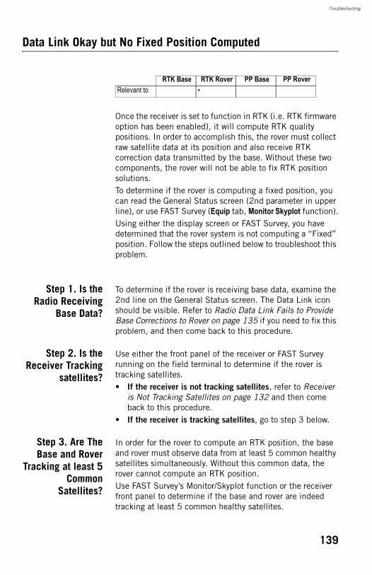
Troubleshooting
Data Link Okay but No Fixed Position Computed
Once the receiver is set to function in RTK (i.e. RTK firmware option has been enabled), it will compute RTK quality positions. In order to accomplish this, the rover must collect raw satellite data at its position and also receive RTK correction data transmitted by the base. Without these two components, the rover will not be able to fix RTK position solutions.To determine if the rover is computing a fixed position, you can read the General Status screen (2nd parameter in upper line), or use FAST Survey (Equip tab, Monitor Skyplot function).Using either the display screen or FAST Survey, you have determined that the rover system is not computing a “Fixed” position. Follow the steps outlined below to troubleshoot this problem.
Step 1. Is theRadio Receiving
Base Data?
To determine if the rover is receiving base data, examine the 2nd line on the General Status screen. The Data Link icon should be visible. Refer to Radio Data Link Fails to Provide Base Corrections to Rover on page 135 if you need to fix this problem, and then come back to this procedure.
Step 2. Is theReceiver Tracking
satellites?
Use either the front panel of the receiver or FAST Survey running on the field terminal to determine if the rover is tracking satellites.• If the receiver is not tracking satellites, refer to Receiver
is Not Tracking Satellites on page 132 and then come back to this procedure.
• If the receiver is tracking satellites, go to step 3 below.
Step 3. Are TheBase and Rover
Tracking at least 5Common
Satellites?
In order for the rover to compute an RTK position, the base and rover must observe data from at least 5 common healthy satellites simultaneously. Without this common data, the rover cannot compute an RTK position.Use FAST Survey’s Monitor/Skyplot function or the receiver front panel to determine if the base and rover are indeed tracking at least 5 common healthy satellites.
RTK Base RTK Rover PP Base PP RoverRelevant to •
139
Troubleshooting
1. If the base and rover are not tracking at least 5 common
satellites:• Check satellite availability. Use the Mission Planning
utility from GNSS Solutions to check satellite availability for your current location and time. Look for the number of satellites available higher than 5° above the horizon. Ensure at least 5 healthy satellites are available. If not, you will need to perform your survey at another time.If the problem is not yet resolved and at least 5 satellites are now tracked and used, your rover may be malfunctioning. Contact your local dealer or email Magellan technical support for assistance.
• Move the base or rover if sites have satellite obstructions. If your base or rover site has any obstructions 5° above the horizon, the obstructions may be blocking essential satellites. If obstructions exist at the base or the rover, move the system to an open area.If the problem is not yet resolved and at least 5 satellites are now tracked and used, your rover may be malfunctioning. Contact your local dealer or email Magellan technical support for assistance.
2. If the base and rover are tracking at least 5 common satellites, your rover may be malfunctioning. Contact your local dealer or email Magellan technical support for assistance.
Rover is Computing Positions with High Uncertainties
Using FAST Survey, you find that the rover is computing a position but the uncertainties (HRMS, VRMS) assigned to the position are unacceptably high. Follow the steps outlined below to troubleshoot this problem.
Step 1. Is theReceiver Set to
Function as an RTKRover?
The rover must be set to function in RTK rover mode in order for it to compute accurate RTK positions. If the rover is not set in RTK rover mode, the receiver will compute autonomous positions which could contain about 10 meters or more of error. This is probably the problem if HRMS and VRMS values
RTK Base RTK Rover PP Base PP RoverRelevant to •
140
Troubleshooting
are in the 10s of meters. Use FAST Survey to determine if the system is configured as an RTK rover.• If the receiver is not set to function as an RTK rover, go to
the Equip menu>GPS Rover>RTK tab and set the different parameters to match your application.
• If the receiver is set to function as an RTK rover, go to step 2.
Step 2. Are theBase and Rover
Tracking at least 5common
Satellites?
Although the rover is capable of computing a position with only 4 common healthy satellites with the base, the rover will not attempt to fix ambiguities unless 5 common healthy satellites are observed. Fixing ambiguities is a required process for the rover to compute highly precise RTK positions. FAST Survey and the receiver will inform you if you currently have a fixed ambiguity solution or a float ambiguity solution. Your field application software will also inform you which satellites are being tracked by the base and which are being tracked by the rover and whether or not these satellites are healthy. If you find that your solution will not fix, look to determine if the base and rover are indeed tracking at least 5 common healthy satellites.1. If the base and rover are not tracking at least 5 satellites:
• Check satellite availability. Use the Mission Planning utility from GNSS Solutions to check satellite availability for your current location and time. Look for the number of satellites higher than 5° above the horizon. Ensure at least 5 healthy satellites are available. If not, you will need to perform your survey at another time.Go to step 3 below if the problem is not yet resolved.
• Move the base or rover if sites have satellite obstruction. If your base or rover site has any obstructions higher than 5° above the horizon, the obstructions may be blocking essential satellites. If obstructions exist at the base or rover, move the system to an open area.Go to step 3 below if the problem is not yet resolved.
2. If the base and rover are tracking at least 5 satellites, go to step 3 below.
141
Troubleshooting
Step 3. Are HDOP& VDOP Values TooHigh for Precision
Requirements?
Dilution of Precision (DOP) values give a quality indication of the satellite geometry at any given time. Satellite geometry is important to the precision of an RTK solution.In fact, the DOP value is used as a multiplier in the computation of position precision. For example, in the computation of horizontal RMS (HRMS), an estimated precision value is multiplied by the HDOP at that given time to produce HRMS. The larger the HDOP value, the larger the HRMS value. The same relationship holds for VDOP and VRMS.Therefore, poor satellite geometry will result in poor solution precision. The smaller the DOP value, the better the geometry and solution precision.FAST Survey can view current DOP values. If your precision estimates (HRMS, VRMS) do not meet expected values, use this feature to examine the current DOP values.1. If DOP values are too high, look for a satellite window with
more suitable DOP values to perform the survey:Use the Mission Planning utility from GNSS Solutions to examine expected DOP values for periods during which you would like to perform your survey. Avoid surveying during periods where DOP values are above 4. For the highest level of accuracy, limit surveying to periods where DOP values are between 1 and 2.Remember that obstructions to line of sight between the GPS antenna and the satellites will block out satellite signals. Every time a satellite is lost due to obstructions, DOP values will be adversely affected. An obstructed area may not be suitable to meet your precision needs due to the adverse effect on satellite geometry.
2. If DOP values are not too high, go to step 4 below.
Step 4. ArePrecision
Requirements TooStringent for RTK?
If the RTK system is not delivering the precision requirements you need for your specific task, it is possible that your precision requirements are too stringent for the RTK system. Review your system documentation to determine the precision specifications for the RTK system.• If the precision is not beyond capability, then the rover
may be malfunctioning. Contact your local dealer or email Magellan technical support for assistance.
• If the precision is beyond capability, your precision requirements are not attainable through RTK surveying. You will need to find some other measurement system to perform your survey.
142

Troubleshooting
This concludes the troubleshooting section. If the tips given here did not help you to resolve your problem with your system, please call your local dealer or email Magellan Technical Support for assistance.
143

Troubleshooting
144
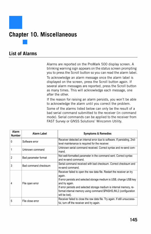
Chapter 10. Miscellaneous
List of Alarms
Alarms are reported on the ProMark 500 display screen. A blinking warning sign appears on the status screen prompting you to press the Scroll button so you can read the alarm label.To acknowledge an alarm message once the alarm label is displayed on the screen, press the Scroll button again. If several alarm messages are reported, press the Scroll button as many times. This will acknowledge each message, one after the other.If the reason for raising an alarm persists, you won’t be able to acknowledge the alarm until you correct the problem.Some of the alarms listed below can only be the result of a bad serial command submitted to the receiver (in command mode). Serial commands can be applied to the receiver from FAST Survey or GNSS Solutions’ Wincomm Utility.
Alarm Number Alarm Label Symptoms & Remedies
0 Software error Receiver detected an internal error due to software. If persisting, 2nd-level maintenance is required for the receiver.
1 Unknown command Unknown serial command received. Correct syntax and re-send com-mand.
2 Bad parameter format Not well-formatted parameter in the command sent. Correct syntax and re-send command.
3 Bad command checksum Serial command received with bad checksum. Correct checksum and re-send command.
4 File open error
Receiver failed to open the raw data file. Restart the receiver an try again.If error persists and selected storage medium is USB, change USB key and try again.If error persists and selected storage medium is internal memory, re-format internal memory using command $PASHS,INI,2 (configuration will be lost).
5 File close error Receiver failed to close the raw data file. Try again. If still unsuccess-ful, turn off the receiver and try again.
145
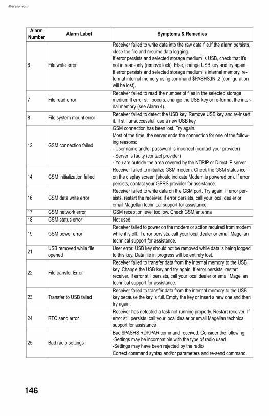
Miscellaneous
6 File write error
Receiver failed to write data into the raw data file.If the alarm persists, close the file and resume data logging.If error persists and selected storage medium is USB, check that it’s not in read-only (remove lock). Else, change USB key and try again.If error persists and selected storage medium is internal memory, re-format internal memory using command $PASHS,INI,2 (configuration will be lost).
7 File read errorReceiver failed to read the number of files in the selected storage medium.If error still occurs, change the USB key or re-format the inter-nal memory (see Alarm 4).
8 File system mount error Receiver failed to detect the USB key. Remove USB key and re-insert it. If still unsuccessful, use a new USB key.
12 GSM connection failed
GSM connection has been lost. Try again.Most of the time, the server ends the connection for one of the follow-ing reasons:- User name and/or password is incorrect (contact your provider)- Server is faulty (contact provider)- You are outside the area covered by the NTRIP or Direct IP server.
14 GSM initialization failedReceiver failed to initialize GSM modem. Check the GSM status icon on the display screen (should indicate Modem is powered on). If error persists, contact your GPRS provider for assistance.
16 GSM data write errorReceiver failed to write data on the GSM port. Try again. If error per-sists, restart the receiver. If error persists, call your local dealer or email Magellan technical support for assistance.
17 GSM network error GSM reception level too low. Check GSM antenna18 GSM status error Not used
19 GSM power errorReceiver failed to power on the modem or action required from modem while it is off. If error persists, call your local dealer or email Magellan technical support for assistance.
21 USB removed while file opened
User error. USB key should not be removed while data is being logged to this key. Data file in progress will be entirely lost.
22 File transfer Error
Receiver failed to transfer data from the internal memory to the USB key. Change the USB key and try again. If error persists, restart receiver. If error still persists, call your local dealer or email Magellan technical support for assistance.
23 Transfer to USB failedReceiver failed to transfer data from the internal memory to the USB key because the key is full. Empty the key or insert a new one and then try again.
24 RTC send errorReceiver has detected a task not running properly. Restart receiver. If error still persists, call your local dealer or email Magellan technical support for assistance
25 Bad radio settings
Bad $PASHS,RDP,PAR command received. Consider the following:-Settings may be incompatible with the type of radio used-Settings may have been rejected by the radioCorrect command syntax and/or parameters and re-send command.
Alarm Number Alarm Label Symptoms & Remedies
146
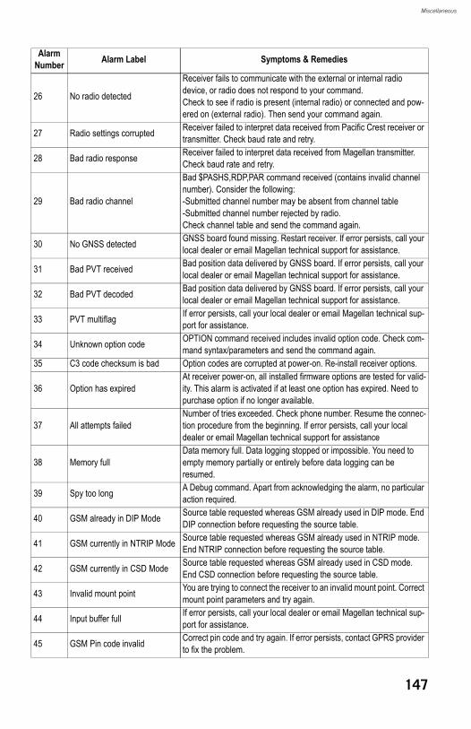
Miscellaneous
26 No radio detected
Receiver fails to communicate with the external or internal radio device, or radio does not respond to your command.Check to see if radio is present (internal radio) or connected and pow-ered on (external radio). Then send your command again.
27 Radio settings corrupted Receiver failed to interpret data received from Pacific Crest receiver or transmitter. Check baud rate and retry.
28 Bad radio response Receiver failed to interpret data received from Magellan transmitter. Check baud rate and retry.
29 Bad radio channel
Bad $PASHS,RDP,PAR command received (contains invalid channel number). Consider the following:-Submitted channel number may be absent from channel table-Submitted channel number rejected by radio.Check channel table and send the command again.
30 No GNSS detected GNSS board found missing. Restart receiver. If error persists, call your local dealer or email Magellan technical support for assistance.
31 Bad PVT received Bad position data delivered by GNSS board. If error persists, call your local dealer or email Magellan technical support for assistance.
32 Bad PVT decoded Bad position data delivered by GNSS board. If error persists, call your local dealer or email Magellan technical support for assistance.
33 PVT multiflag If error persists, call your local dealer or email Magellan technical sup-port for assistance.
34 Unknown option code OPTION command received includes invalid option code. Check com-mand syntax/parameters and send the command again.
35 C3 code checksum is bad Option codes are corrupted at power-on. Re-install receiver options.
36 Option has expiredAt receiver power-on, all installed firmware options are tested for valid-ity. This alarm is activated if at least one option has expired. Need to purchase option if no longer available.
37 All attempts failedNumber of tries exceeded. Check phone number. Resume the connec-tion procedure from the beginning. If error persists, call your local dealer or email Magellan technical support for assistance
38 Memory fullData memory full. Data logging stopped or impossible. You need to empty memory partially or entirely before data logging can be resumed.
39 Spy too long A Debug command. Apart from acknowledging the alarm, no particular action required.
40 GSM already in DIP Mode Source table requested whereas GSM already used in DIP mode. End DIP connection before requesting the source table.
41 GSM currently in NTRIP Mode Source table requested whereas GSM already used in NTRIP mode. End NTRIP connection before requesting the source table.
42 GSM currently in CSD Mode Source table requested whereas GSM already used in CSD mode. End CSD connection before requesting the source table.
43 Invalid mount point You are trying to connect the receiver to an invalid mount point. Correct mount point parameters and try again.
44 Input buffer full If error persists, call your local dealer or email Magellan technical sup-port for assistance.
45 GSM Pin code invalid Correct pin code and try again. If error persists, contact GPRS provider to fix the problem.
Alarm Number Alarm Label Symptoms & Remedies
147
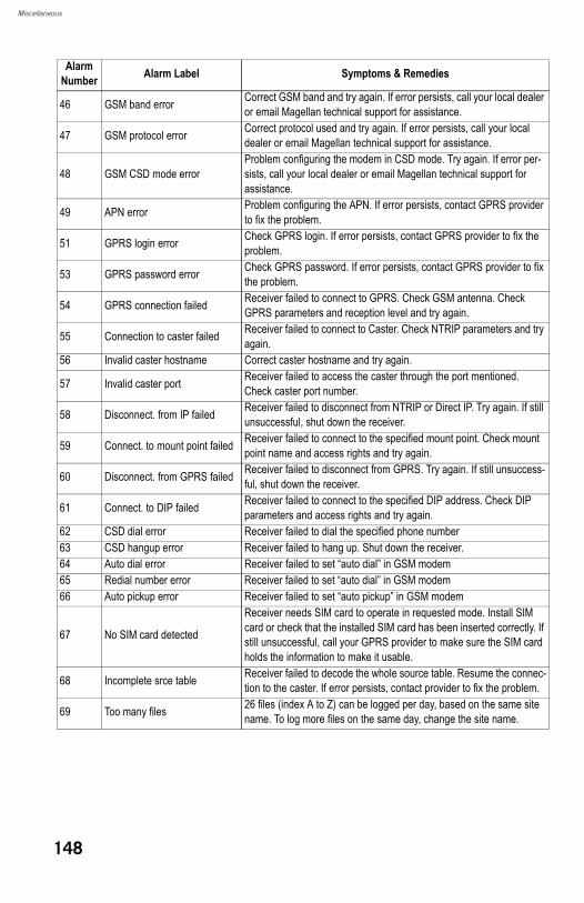
Miscellaneous
46 GSM band error Correct GSM band and try again. If error persists, call your local dealer or email Magellan technical support for assistance.
47 GSM protocol error Correct protocol used and try again. If error persists, call your local dealer or email Magellan technical support for assistance.
48 GSM CSD mode errorProblem configuring the modem in CSD mode. Try again. If error per-sists, call your local dealer or email Magellan technical support for assistance.
49 APN error Problem configuring the APN. If error persists, contact GPRS provider to fix the problem.
51 GPRS login error Check GPRS login. If error persists, contact GPRS provider to fix the problem.
53 GPRS password error Check GPRS password. If error persists, contact GPRS provider to fix the problem.
54 GPRS connection failed Receiver failed to connect to GPRS. Check GSM antenna. Check GPRS parameters and reception level and try again.
55 Connection to caster failed Receiver failed to connect to Caster. Check NTRIP parameters and try again.
56 Invalid caster hostname Correct caster hostname and try again.
57 Invalid caster port Receiver failed to access the caster through the port mentioned. Check caster port number.
58 Disconnect. from IP failed Receiver failed to disconnect from NTRIP or Direct IP. Try again. If still unsuccessful, shut down the receiver.
59 Connect. to mount point failed Receiver failed to connect to the specified mount point. Check mount point name and access rights and try again.
60 Disconnect. from GPRS failed Receiver failed to disconnect from GPRS. Try again. If still unsuccess-ful, shut down the receiver.
61 Connect. to DIP failed Receiver failed to connect to the specified DIP address. Check DIP parameters and access rights and try again.
62 CSD dial error Receiver failed to dial the specified phone number63 CSD hangup error Receiver failed to hang up. Shut down the receiver.64 Auto dial error Receiver failed to set “auto dial” in GSM modem65 Redial number error Receiver failed to set “auto dial” in GSM modem66 Auto pickup error Receiver failed to set “auto pickup” in GSM modem
67 No SIM card detected
Receiver needs SIM card to operate in requested mode. Install SIM card or check that the installed SIM card has been inserted correctly. If still unsuccessful, call your GPRS provider to make sure the SIM card holds the information to make it usable.
68 Incomplete srce table Receiver failed to decode the whole source table. Resume the connec-tion to the caster. If error persists, contact provider to fix the problem.
69 Too many files 26 files (index A to Z) can be logged per day, based on the same site name. To log more files on the same day, change the site name.
Alarm Number Alarm Label Symptoms & Remedies
148
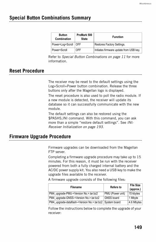
Miscellaneous
Special Button Combinations Summary
Refer to Special Button Combinations on page 11 for more information.
Reset Procedure
The receiver may be reset to the default settings using the Log+Scroll+Power button combination. Release the three buttons only after the Magellan logo is displayed.The reset procedure is also used to poll the radio module. If a new module is detected, the receiver will update its database so it can successfully communicate with the new module.The default settings can also be restored using the $PASHS,INI command. With this command, you can ask more than a simple “restore default settings”. See INI: Receiver Initialization on page 193.
Firmware Upgrade Procedure
Firmware upgrades can be downloaded from the Magellan FTP server.Completing a firmware upgrade procedure may take up to 15 minutes. For this reason, it must be run with the receiver powered from both a fully charged internal battery and the AC/DC power supply kit. You also need a USB key to make the upgrade files available to the receiver.A firmware upgrade consists of the following files:
Follow the instructions below to complete the upgrade of your receiver:
Button Combination
ProMark 500 State Function
Power+Log+Scroll OFF Restores Factory Settings.
Power+Scroll OFF Initiates firmware update from USB key.
Filename Refers to File Size (approx.)
PM4_upgrade-PMU-<Version No.>.tar.bz2 PMU (Power unit) 15 kbytesPM4_upgrade-GNSS-<Version No.>.tar.bz2 GNSS board 1 MbytePM4_upgrade-dataflash-<Version No.>.tar.bz2 System board 4.6 Mbytes
149
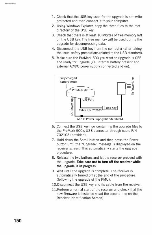
Miscellaneous
1. Check that the USB key used for the upgrade is not write-protected and then connect it to your computer.
2. Using Windows Explorer, copy the three files to the root directory of the USB key.
3. Check that there is at least 10 Mbytes of free memory left on the USB key. The free memory will be used during the upgrade for decompressing data.
4. Disconnect the USB key from the computer (after taking the usual safety precautions related to the USB standard).
5. Make sure the ProMark 500 you want to upgrade is OFF and ready for upgrade (i.e. internal battery present and external AC/DC power supply connected and on).
6. Connect the USB key now containing the upgrade files to the ProMark 500’s USB connector through cable P/N 702103 (provided).
7. Hold down the Scroll button and then press the Power button until the “Upgrade” message is displayed on the receiver screen. This automatically starts the upgrade procedure.
8. Release the two buttons and let the receiver proceed with the upgrade. Take care not to turn off the receiver while
the upgrade is in progress.9. Wait until the upgrade is complete. The receiver is
automatically turned off at the end of the procedure (following the upgrade of the PMU).
10.Disconnect the USB key and its cable from the receiver.11.Perform a normal start of the receiver and check that the
new firmware is installed (read the second line on the Receiver Identification Screen).
Fully chargedbattery inside
DC
Po
wer
Inp
ut
USB Port
To P
ow
er L
ine
ProMark 500
Cable P/N 702103
AC/DC Power Supply Kit P/N 802064
USB Key
150
Miscellaneous
Time-tagged RTK vs. FAST RTK Position Output
The ProMark 500 can deliver RTK positions either in Time-Tagged or Fast RTK mode. The default mode is Fast RTK.In this default mode, in fact the ProMark 500 automatically switches from Time-Tagged to Fast RTK depending on context: • When assisting you in your navigation to a point, the
receiver will operate in Fast RTK mode. In this case, all satellites received above the elevation mask, including those for which the base is unable to provide corrections, will be used in the position processing for best availability of an RTK position.
• When you are about to log a point, the ProMark 500 will automatically switch to Time-Tagged RTK for best accuracy. In this case, only those satellites above the elevation mask for which corrections are provided by the base will be used in the position processing.
If you wish your receiver to always operate in Time-Tagged mode, use the appropiate serial command to switch into that mode (see CPD,FST: RTK Output Mode on page 181).In its standard version, the ProMark 500 features a Fast RTK mode with an output rate of 5 Hz. With the FASTOUTPUT10 firmware option, the output rate is 10 Hz. After purchasing this option, use the $PASHS,OPTION command to install it. See OPTION: Receiver Firmware Options on page 211).
ATOM File Naming Conventions
Raw data files in ATOM format are named using the following syntax:
G<Site><Index><Year>.<Day>
Where:
Item in Filename Description
G Header indicative of a file containing ATOM data.
<Site>
A 4-character string recalling the name of the site where data was collected (a point name in static, a trajectory name in kinematic, or name of last surveyed point in stop & go). The default string is four underscores (“____”).
<Index> Order number of file being recorded (A.. Z, where “A” is used for the first file logged in current day).
<Year> Last two figures of current year (e.g. “08” for 2008).
151
Miscellaneous
Example of first file logged on May 6th 2008 on point 584V:G584VA08.127
Saving/Restoring Base and Rover Configurations
FAST Survey allows you to save into a file all the settings you have prepared for your base or rover.This function is useful when you regularly have to switch between two or more configurations. By simply selecting the right configuration, you immediately restore all the settings FAST Survey needs to load to the receiver before the receiver/field terminal system can operate as expected.The table below summarizes the parameters held in a configuration file.
For network connections, the file includes the provider’s connection parameters as well as, for NTRIP, the last reference station selected from the source table. Needless to say in these cases, you’ll really save time when starting your system if you first take a couple of seconds to save your configurations. FAST Survey manages base and rover configurations independently of job files. All saved configurations are potentially usable in all new jobs and whatever the existing jobs you re-open, provided the hardware available matches the configuration.The two procedures described below apply to either a base or rover.
.<Day> File extension: a three-figure number representing the cur-rent day number in year (1.. 365).
Item in Filename Description
Parameters Base RoverEquipment manufacturer • •Equipment model • •Communication Type (Bluetooth or other) • •Antenna height measurement type and value • •Elevation mask • •Ambiguity fixing •Use SBAS satellites • •Use GLONASS satellites • •Device used in RTK data link and device settings • •
152
Miscellaneous
Saving aConfiguration
• Tap Equip then GPS Base for a base, or GPS Rover for a rover.
• Enter all the parameters needed to set the equipment in the four tabs presented in this window.
• Before you tap to load the configuration to the receiver, come back to the Current tab.
• Tap on the Save button located in the lower part of the window and then name the configuration (e.g. “Radio” or “NTRIP”).
• Name the configuration file and tap . This takes you back to the current tab where the new configuration is now listed.
Making a SavedConfiguration the
CurrentConfiguration
• Tap Equip then GPS Base for a base, or GPS Rover for a rover.
• Select the name of the desired configuration from the lower list.
• Tap on the Load button.• Tap Yes to confirm your choice. This restores all the
settings held in this configuration. You may check this by scrolling all the tabs in the window.
• Tap to load the configuration to the receiver.
Setting the Base Position With FAST Survey
This section is a supplement to the section Set Base Position on page 35 where the procedure is only outlined.For theoretical aspects, see also Choosing a Location for the Base on page 82.Depending on how you chose the base site (is its position known or unknown?), choose either From Known Position, for known position, or From New Position, for unknown position. Then of the three possible choices, choose the one that suits your job.
Known BasePosition
153
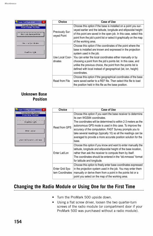
Miscellaneous
Unknown BasePosition
Changing the Radio Module or Using One for the First Time
• Turn the ProMark 500 upside down.• Using a flat screw driver, loosen the two quarter-turn
screws of the radio module (or compartment door if your ProMark 500 was purchased without a radio module).
Choice Case of Use
Previously Sur-veyed Point
Choose this option if the base is installed on a point you sur-veyed earlier and the latitude, longitude and ellipsoidal height of this point are saved in the open job. In this case, select this point from the job’s point list or select it graphically on the map of the working area.
Use Local Coor-dinates
Choose this option if the coordinates of the point where the base is installed are known and expressed in the projection system used in the job.You can enter the local coordinates either manually or by choosing a point from the job’s points list. In this case, and unlike the previous choice, the point from the points list is defined with local instead of geographical (lat, lon, height) coordinates.
Read from FileChoose this option if the geographical coordinates of the base were saved earlier to a REF file. Then select this file to load the position held in this file as the base position.
Choice Case of Use
Read from GPS
Choose this option if you want the base receiver to determine its own WGS84 coordinates.The coordinates will be determined to within 2-3 meters as the autonomous GPS mode is used in this case. To improve the accuracy of the computation, FAST Survey prompts you to take several readings (typically 10) so all the readings can be averaged to provide a more accurate position solution for the base.
Enter Lat/Lon
Choose this option if you know and want to enter manually the latitude, longitude and ellipsoidal height of the base location, rather than ask the receiver to compute them by itself.The coordinates should be entered in the “dd.mmssss” format for latitude and longitude.
Enter Grid Sys-tem Coordinates
Choose this option to freely enter base coordinates expressed in the projection system used in the job. You may enter them manually or derive them from a point in the points list or a point you select on the map of the working area.
154
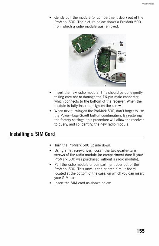
Miscellaneous
• Gently pull the module (or compartment door) out of the ProMark 500. The picture below shows a ProMark 500 from which a radio module was removed.
• Insert the new radio module. This should be done gently, taking care not to damage the 16-pin male connector, which connects to the bottom of the receiver. When the module is fully inserted, tighten the screws.
• When next turning on the ProMark 500, don’t forget to use the Power+Log+Scroll button combination. By restoring the factory settings, this procedure will allow the receiver to query, and so identify, the new radio module.
Installing a SIM Card
• Turn the ProMark 500 upside down.• Using a flat screwdriver, loosen the two quarter-turn
screws of the radio module (or compartment door if your ProMark 500 was purchased without a radio module).
• Pull the radio module or compartment door out of the ProMark 500. This unveils the printed circuit board located at the bottom of the case, on which you can insert your SIM card.
• Insert the SIM card as shown below.
155
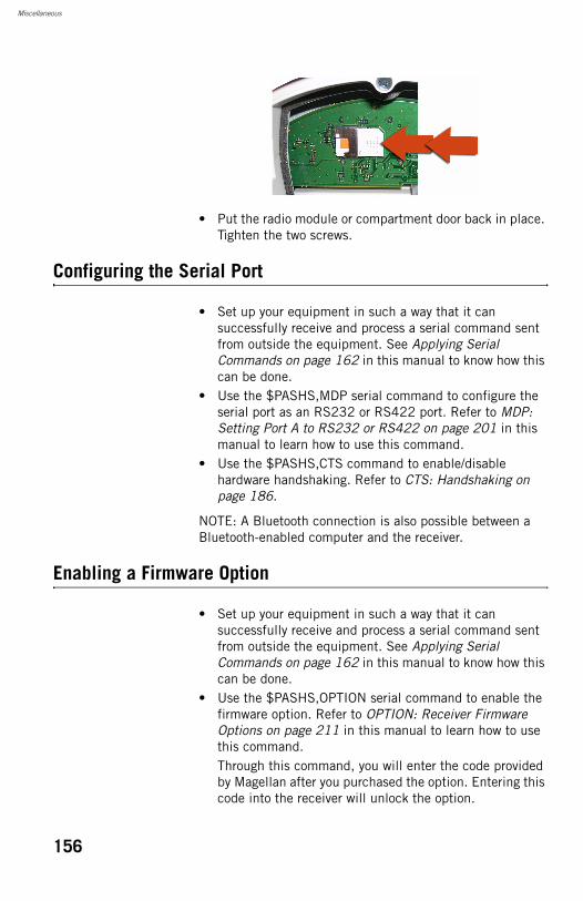
Miscellaneous
• Put the radio module or compartment door back in place. Tighten the two screws.
Configuring the Serial Port
• Set up your equipment in such a way that it can successfully receive and process a serial command sent from outside the equipment. See Applying Serial Commands on page 162 in this manual to know how this can be done.
• Use the $PASHS,MDP serial command to configure the serial port as an RS232 or RS422 port. Refer to MDP: Setting Port A to RS232 or RS422 on page 201 in this manual to learn how to use this command.
• Use the $PASHS,CTS command to enable/disable hardware handshaking. Refer to CTS: Handshaking on page 186.
NOTE: A Bluetooth connection is also possible between a Bluetooth-enabled computer and the receiver.
Enabling a Firmware Option
• Set up your equipment in such a way that it can successfully receive and process a serial command sent from outside the equipment. See Applying Serial Commands on page 162 in this manual to know how this can be done.
• Use the $PASHS,OPTION serial command to enable the firmware option. Refer to OPTION: Receiver Firmware Options on page 211 in this manual to learn how to use this command.Through this command, you will enter the code provided by Magellan after you purchased the option. Entering this code into the receiver will unlock the option.
156
Miscellaneous
Using a Geoid File in the Localization Process
Uploading a GeoidFile to the Field
Terminal
Use GNSS Solutions’ Geoids utility exclusively to upload a geoid file to the field terminal.From a given geoid model, the Geoids utility allows you to extract part of the open geoid corresponding to your working area before uploading the data to the field terminal. This results in a smaller file in the field terminal. Follow the instructions below to upload a geoid file. • Turn on your office computer and field terminal.• Connect a USB cable between your office computer and
field terminal.• Run GNSS Solutions’ Geoids utility on your office
computer.• In Geoids, use the File>Open command to open the geoid
model you wish to use• Use the File>Extract as command and define the limits of
the geoid corresponding to your working area.• Name the resulting geoid and click on the Extract button.
A new window opens in Geoids showing the properties of your geoid extraction.
• Select Transfer>Write. • Select “FAST Survey data collector” in the upper field and
click OK.• Select “ActiveSync” as the communication type between
the computer and the field terminal and “Automatic Transfer”.
• Click OK. This starts the data transfer. Wait until the “Transfer complete” message is displayed. The geoid file can now be found on the field terminal in \MyDevice\FAST Survey\Data\ as a *.GSF file.
Selecting a GeoidFile for Use inFAST Survey’s
LocalizationProcess
In FAST Survey, do the following:• In the Equip menu, tap on the Localization button.• Tap on the GPS tab.• Tap on the Geoid File: button. This opens the
\MyDevice\FAST Survey\Data\ folder from which you can now select the geoid file you have just uploaded.
• Select the file and tap . The name of the geoid file now appears underneath the Geoid File: button, meaning that from now on, it is used in the localization procedure for the processing of elevations.
157

Miscellaneous
Using a ProMark3 RTK Rover with a ProMark 500 RTK Base
The ProMark 500 can serve as a base for ProMark3 RTK rovers.In this configuration, a radio link is used between the ProMark 500 and the ProMark3 RTK to transfer base corrections to rovers.The ProMark 500 will use a Magellan or Pac Crest transmitter and the ProMark3 RTK a Pac Crest radio receiver (“stick” type).The ProMark 500 should be set up to broadcast corrections in RTCM3.1 format.The range of the radio link will be that of the ProMark 500 radio transmitter.
158
ProMark 500 Serial Commands
Supplement

ProMark 500 Serial Commands Supplement
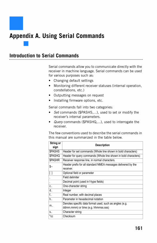
Appendix A. Using Serial Commands
Introduction to Serial Commands
Serial commands allow you to communicate directly with the receiver in machine language. Serial commands can be used for various purposes such as:• Changing default settings• Monitoring different receiver statuses (internal operation,
constellations, etc.)• Outputting messages on request• Installing firmware options, etc.
Serial commands fall into two categories:• Set commands ($PASHS,...), used to set or modify the
receiver’s internal parameters.• Query commands ($PASHQ,...), used to interrogate the
receiver.
The few conventions used to describe the serial commands in this manual are summarized in the table below.
String or sign Description
$PASHS Header for set commands (Whole line shown in bold characters)$PASHQ Header for query commands (Whole line shown in bold characters)$PASHR Receiver response line, in normal characters.
$-- Header prefix for all standard NMEA messages delivered by the receiver.
[ ] Optional field or parameter, Field delimiter. Decimal point (used in f-type fields)c.. One-character stringd.. Integerf.. Real number, with decimal placesh.. Parameter in hexadecimal notation
m.. Denotes specific data format used, such as angles (e.g. ddmm.mmm) or time (e.g. hhmmss.sss)
s.. Character string*cc Checksum
161
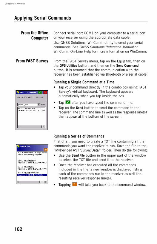
Using Serial Commands
Applying Serial Commands
From the OfficeComputer
Connect serial port COM1 on your computer to a serial port on your receiver using the appropriate data cable.Use GNSS Solutions’ WinComm utility to send your serial commands. See GNSS Solutions Reference Manual or WinComm On-Line Help for more information on WinComm.
From FAST Survey From the FAST Survey menu, tap on the Equip tab, then on the GPS Utilities button, and then on the Send Command button. It is assumed that the communication with the receiver has been established via Bluetooth or a serial cable.
Running a Single Command at a Time• Tap your command directly in the combo box using FAST
Survey’s virtual keyboard. The keyboard appears automatically when you tap inside the box.
• Tap after you have typed the command line.• Tap on the Send button to send the command to the
receiver. The command line as well as the response line(s) then appear at the bottom of the screen.
Running a Series of CommandsFirst of all, you need to create a TXT file containing all the commands you want the receiver to run. Save the file to the “MyDevice/FAST Survey/Data/” folder. Then do the following:• Use the Send File button in the upper part of the window
to select the TXT file and send it to the receiver.• Once the receiver has executed all the commands
included in the file, a new window is displayed listing each of the commands run in the receiver as well the resulting receiver response line(s).
• Tapping will take you back to the command window.
162
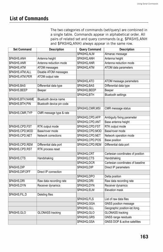
Using Serial Commands
List of Commands
The two categories of commands (set/query) are combined in a single table. Commands appear in alphabetical order. All pairs of related set and query commands (e.g. $PASHS,ANH and $PASHQ,ANH) always appear in the same row.
Set Command Description Query Command Description$PASHQ,ALM Almanac message
$PASHS,ANH Antenna height $PASHQ,ANH Antenna height$PASHS,ANR Antenna reduction mode $PASHQ,ANR Antenna reduction mode$PASHS,ATM ATOM messages $PASHQ,ATM ATOM data parameters$PASHS,ATM,ALL Disable ATOM messages$PASHS,ATM,PER ATOM output rate
$PASHQ,ATO ATOM message parameters$PASHS,BAS Differential data type $PASHQ,BAS DIfferential data type$PASHS,BEEP Beeper $PASHQ,BEEP Beeper
$PASHQ,BTH Bluetooth settings$PASHS,BTH,NAME Bluetooth device name$PASHS,BTH,PIN Bluetooth device pin code
$PASHQ,CMR,MSI CMR message status$PASHS,CMR,TYP CMR message type & rate
$PASHQ,CPD,AFP Ambiguity fixing parameter$PASHQ,CPD,ANT Base antenna height
$PASHS,CPD,FST RTK output mode $PASHQ,CPD,FST RTK output mode$PASHS,CPD,MOD Base/rover mode $PASHQ,CPD,MOD Base/rover mode$PASHS,CPD,NET Network corrections $PASHQ,CPD,NET Network operation mode
$PASHQ,CPD,POS Base position$PASHS,CPD,REM Differential data port $PASHQ,CPD,REM Differential data port$PASHS,CPD,RST RTK process reset
$PASHQ,CRT Cartesian coordinates of position$PASHS,CTS Handshaking $PASHQ,CTS Handshaking
$PASHQ,DCR Cartesian coordinates of baseline$PASHS,DIP $PASHQ,DIP Direct IP parameters$PASHS,DIP,OFF Direct IP connection
$PASHQ,DPO Delta position$PASHS,DRI Raw data recording rate $PASHQ,DRI Raw data recording rate$PASHS,DYN Receiver dynamics $PASHQ,DYN Receiver dynamics
$PASHQ,ELM Elevation mask$PASHS,FIL,D Deleting files
$PASHQ,FLS List of raw data files$PASHQ,GGA GNSS position message$PASHQ,GLL Geographic position-lat./long.
$PASHS,GLO GLONASS tracking $PASHQ,GLO GLONASS tracking$PASHQ,GRS GNSS range residuals$PASHQ,GSA GNSS DOP & active satellites
163
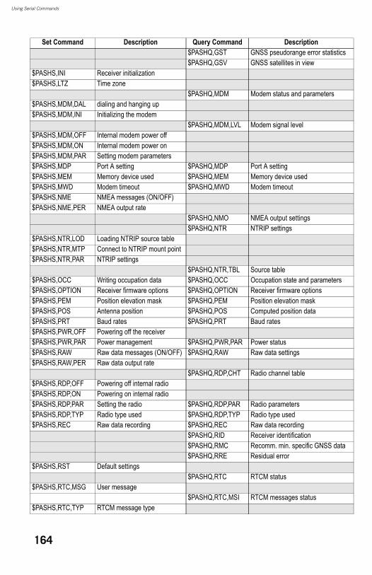
Using Serial Commands
$PASHQ,GST GNSS pseudorange error statistics$PASHQ,GSV GNSS satellites in view
$PASHS,INI Receiver initialization$PASHS,LTZ Time zone
$PASHQ,MDM Modem status and parameters$PASHS,MDM,DAL dialing and hanging up$PASHS,MDM,INI Initializing the modem
$PASHQ,MDM,LVL Modem signal level$PASHS,MDM,OFF Internal modem power off$PASHS,MDM,ON Internal modem power on$PASHS,MDM,PAR Setting modem parameters$PASHS,MDP Port A setting $PASHQ,MDP Port A setting$PASHS,MEM Memory device used $PASHQ,MEM Memory device used$PASHS,MWD Modem timeout $PASHQ,MWD Modem timeout$PASHS,NME NMEA messages (ON/OFF)$PASHS,NME,PER NMEA output rate
$PASHQ,NMO NMEA output settings$PASHQ,NTR NTRIP settings
$PASHS,NTR,LOD Loading NTRIP source table$PASHS,NTR,MTP Connect to NTRIP mount point$PASHS,NTR,PAR NTRIP settings
$PASHQ,NTR,TBL Source table$PASHS,OCC Writing occupation data $PASHQ,OCC Occupation state and parameters$PASHS,OPTION Receiver firmware options $PASHQ,OPTION Receiver firmware options$PASHS,PEM Position elevation mask $PASHQ,PEM Position elevation mask$PASHS,POS Antenna position $PASHQ,POS Computed position data$PASHS,PRT Baud rates $PASHQ,PRT Baud rates$PASHS,PWR,OFF Powering off the receiver$PASHS,PWR,PAR Power management $PASHQ,PWR,PAR Power status$PASHS,RAW Raw data messages (ON/OFF) $PASHQ,RAW Raw data settings$PASHS,RAW,PER Raw data output rate
$PASHQ,RDP,CHT Radio channel table$PASHS,RDP,OFF Powering off internal radio$PASHS,RDP,ON Powering on internal radio$PASHS,RDP,PAR Setting the radio $PASHQ,RDP,PAR Radio parameters$PASHS,RDP,TYP Radio type used $PASHQ,RDP,TYP Radio type used$PASHS,REC Raw data recording $PASHQ,REC Raw data recording
$PASHQ,RID Receiver identification$PASHQ,RMC Recomm. min. specific GNSS data$PASHQ,RRE Residual error
$PASHS,RST Default settings$PASHQ,RTC RTCM status
$PASHS,RTC,MSG User message$PASHQ,RTC,MSI RTCM messages status
$PASHS,RTC,TYP RTCM message type
Set Command Description Query Command Description
164
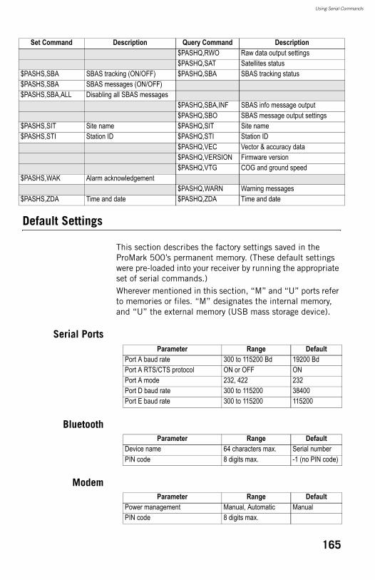
Using Serial Commands
Default Settings
This section describes the factory settings saved in the ProMark 500’s permanent memory. (These default settings were pre-loaded into your receiver by running the appropriate set of serial commands.)Wherever mentioned in this section, “M” and “U” ports refer to memories or files. “M” designates the internal memory, and “U” the external memory (USB mass storage device).
Serial Ports
Bluetooth
Modem
$PASHQ,RWO Raw data output settings$PASHQ,SAT Satellites status
$PASHS,SBA SBAS tracking (ON/OFF) $PASHQ,SBA SBAS tracking status$PASHS,SBA SBAS messages (ON/OFF)$PASHS,SBA,ALL Disabling all SBAS messages
$PASHQ,SBA,INF SBAS info message output$PASHQ,SBO SBAS message output settings
$PASHS,SIT Site name $PASHQ,SIT Site name$PASHS,STI Station ID $PASHQ,STI Station ID
$PASHQ,VEC Vector & accuracy data$PASHQ,VERSION Firmware version$PASHQ,VTG COG and ground speed
$PASHS,WAK Alarm acknowledgement$PASHQ,WARN Warning messages
$PASHS,ZDA Time and date $PASHQ,ZDA Time and date
Set Command Description Query Command Description
Parameter Range DefaultPort A baud rate 300 to 115200 Bd 19200 BdPort A RTS/CTS protocol ON or OFF ONPort A mode 232, 422 232Port D baud rate 300 to 115200 38400Port E baud rate 300 to 115200 115200
Parameter Range DefaultDevice name 64 characters max. Serial numberPIN code 8 digits max. -1 (no PIN code)
Parameter Range DefaultPower management Manual, Automatic ManualPIN code 8 digits max.
165
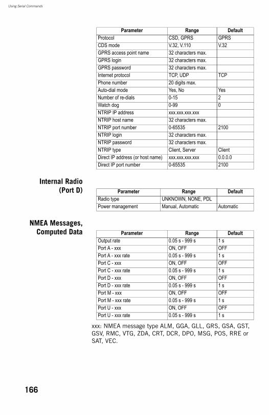
Using Serial Commands
Internal Radio(Port D)
NMEA Messages,Computed Data
xxx: NMEA message type ALM, GGA, GLL, GRS, GSA, GST, GSV, RMC, VTG, ZDA, CRT, DCR, DPO, MSG, POS, RRE or SAT, VEC.
Protocol CSD, GPRS GPRSCDS mode V.32, V.110 V.32GPRS access point name 32 characters max.GPRS login 32 characters max.GPRS password 32 characters max.Internet protocol TCP, UDP TCPPhone number 20 digits max.Auto-dial mode Yes, No YesNumber of re-dials 0-15 2Watch dog 0-99 0NTRIP IP address xxx.xxx.xxx.xxxNTRIP host name 32 characters max.NTRIP port number 0-65535 2100NTRIP login 32 characters max.NTRIP password 32 characters max.NTRIP type Client, Server ClientDirect IP address (or host name) xxx.xxx.xxx.xxx 0.0.0.0Direct IP port number 0-65535 2100
Parameter Range Default
Parameter Range DefaultRadio type UNKNOWN, NONE, PDLPower management Manual, Automatic Automatic
Parameter Range DefaultOutput rate 0.05 s - 999 s 1 sPort A - xxx ON, OFF OFFPort A - xxx rate 0.05 s - 999 s 1 sPort C - xxx ON, OFF OFFPort C - xxx rate 0.05 s - 999 s 1 sPort D - xxx ON, OFF OFFPort D - xxx rate 0.05 s - 999 s 1 sPort M - xxx ON, OFF OFFPort M - xxx rate 0.05 s - 999 s 1 sPort U - xxx ON, OFF OFFPort U - xxx rate 0.05 s - 999 s 1 s
166
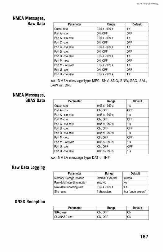
Using Serial Commands
NMEA Messages,Raw Data
xxx: NMEA message type MPC, SNV, SNG, SNW, SAG, SAL, SAW or ION.
NMEA Messages,SBAS Data
xxx: NMEA message type DAT or INF.
Raw Data Logging
GNSS Reception
Parameter Range DefaultOutput rate 0.05 s - 999 s 1 sPort A - xxx ON, OFF OFFPort A - xxx rate 0.05 s - 999 s 1 sPort C - xxx ON, OFF OFFPort C - xxx rate 0.05 s - 999 s 1 sPort D - xxx ON, OFF OFFPort D - xxx rate 0.05 s - 999 s 1 sPort M - xxx ON, OFF OFFPort M - xxx rate 0.05 s - 999 s 1 sPort U - xxx ON, OFF OFFPort U - xxx rate 0.05 s - 999 s 1 s
Parameter Range DefaultOutput rate 0.05 s - 999 s 1 sPort A - xxx ON, OFF OFFPort A - xxx rate 0.05 s - 999 s 1 sPort C - xxx ON, OFF OFFPort C - xxx rate 0.05 s - 999 s 1 sPort D - xxx ON, OFF OFFPort D - xxx rate 0.05 s - 999 s 1 sPort M - xxx ON, OFF OFFPort M - xxx rate 0.05 s - 999 s 1 sPort U - xxx ON, OFF OFFPort U - xxx rate 0.05 s - 999 s 1 s
Parameter Range DefaultMemory Storage location Internal, External InternalRaw data recording mode Yes, No NoRaw data recording rate 0.05 s - 999 s 1 sSite name 4 characters four “underscores”
Parameter Range DefaultSBAS use ON, OFF ONGLONASS use ON, OFF ON
167
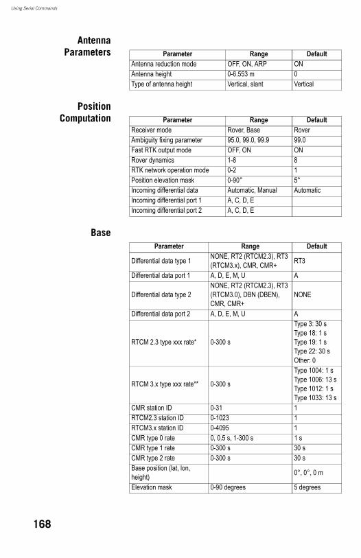
Using Serial Commands
AntennaParameters
PositionComputation
Base
Parameter Range DefaultAntenna reduction mode OFF, ON, ARP ONAntenna height 0-6.553 m 0Type of antenna height Vertical, slant Vertical
Parameter Range DefaultReceiver mode Rover, Base RoverAmbiguity fixing parameter 95.0, 99.0, 99.9 99.0Fast RTK output mode OFF, ON ONRover dynamics 1-8 8RTK network operation mode 0-2 1Position elevation mask 0-90° 5°Incoming differential data Automatic, Manual AutomaticIncoming differential port 1 A, C, D, EIncoming differential port 2 A, C, D, E
Parameter Range Default
Differential data type 1 NONE, RT2 (RTCM2.3), RT3 (RTCM3.x), CMR, CMR+ RT3
Differential data port 1 A, D, E, M, U A
Differential data type 2NONE, RT2 (RTCM2.3), RT3 (RTCM3.0), DBN (DBEN), CMR, CMR+
NONE
Differential data port 2 A, D, E, M, U A
RTCM 2.3 type xxx rate* 0-300 s
Type 3: 30 sType 18: 1 sType 19: 1 sType 22: 30 sOther: 0
RTCM 3.x type xxx rate** 0-300 s
Type 1004: 1 sType 1006: 13 sType 1012: 1 sType 1033: 13 s
CMR station ID 0-31 1RTCM2.3 station ID 0-1023 1RTCM3.x station ID 0-4095 1CMR type 0 rate 0, 0.5 s, 1-300 s 1 sCMR type 1 rate 0-300 s 30 sCMR type 2 rate 0-300 s 30 sBase position (lat, lon, height) 0°, 0°, 0 m
Elevation mask 0-90 degrees 5 degrees
168
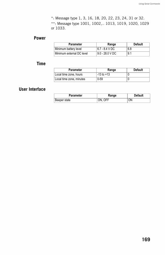
Using Serial Commands
*: Message type 1, 3, 16, 18, 20, 22, 23, 24, 31 or 32.**: Message type 1001, 1002,.. 1013, 1019, 1020, 1029 or 1033.
Power
Time
User Interface
Parameter Range DefaultMinimum battery level 6.7 - 8.4 V DC 6.8Minimum external DC level 9.0 - 28.0 V DC 9.1
Parameter Range DefaultLocal time zone, hours -13 to +13 0Local time zone, minutes 0-59 0
Parameter Range DefaultBeeper state ON, OFF ON
169

Using Serial Commands
170
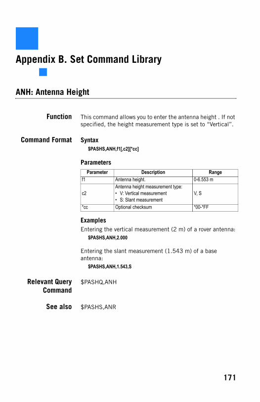
Appendix B. Set Command Library
ANH: Antenna Height
Function This command allows you to enter the antenna height . If not specified, the height measurement type is set to “Vertical”.
Command Format Syntax$PASHS,ANH,f1[,c2][*cc]
Parameters
ExamplesEntering the vertical measurement (2 m) of a rover antenna:
$PASHS,ANH,2.000
Entering the slant measurement (1.543 m) of a base antenna:
$PASHS,ANH,1.543,S
Relevant QueryCommand
$PASHQ,ANH
See also $PASHS,ANR
Parameter Description Rangef1 Antenna height. 0-6.553 m
c2Antenna height measurement type:• V: Vertical measurement• S: Slant measurement
V, S
*cc Optional checksum *00-*FF
171
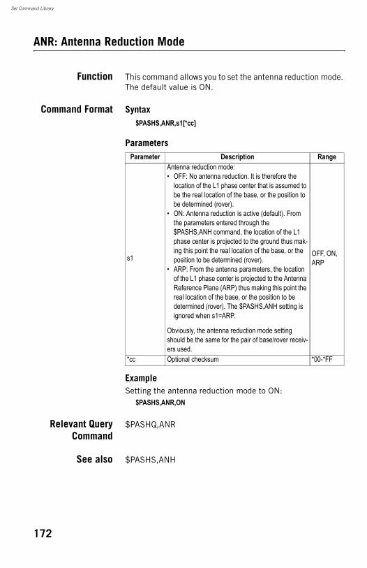
Set Command Library
ANR: Antenna Reduction Mode
Function This command allows you to set the antenna reduction mode. The default value is ON.
Command Format Syntax$PASHS,ANR,s1[*cc]
Parameters
ExampleSetting the antenna reduction mode to ON:
$PASHS,ANR,ON
Relevant QueryCommand
$PASHQ,ANR
See also $PASHS,ANH
Parameter Description Range
s1
Antenna reduction mode:• OFF: No antenna reduction. It is therefore the
location of the L1 phase center that is assumed to be the real location of the base, or the position to be determined (rover).
• ON: Antenna reduction is active (default). From the parameters entered through the $PASHS,ANH command, the location of the L1 phase center is projected to the ground thus mak-ing this point the real location of the base, or the position to be determined (rover).
• ARP: From the antenna parameters, the location of the L1 phase center is projected to the Antenna Reference Plane (ARP) thus making this point the real location of the base, or the position to be determined (rover). The $PASHS,ANH setting is ignored when s1=ARP.
Obviously, the antenna reduction mode setting should be the same for the pair of base/rover receiv-ers used.
OFF, ON, ARP
*cc Optional checksum *00-*FF
172
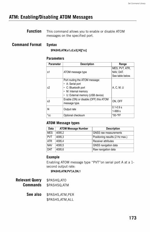
Set Command Library
ATM: Enabling/Disabling ATOM Messages
Function This command allows you to enable or disable ATOM messages on the specified port.
Command Format Syntax$PASHS,ATM,s1,c2,s3[,f4][*cc]
Parameters
ATOM Message types
ExampleEnabling ATOM message type “PVT”on serial port A at a 1-second output rate:
$PASHS,ATM,PVT,A,ON,1
Relevant QueryCommands
$PASHQ,ATO$PASHSQ,ATM
See also $PASHS,ATM,PER$PASHS,ATM,ALL
Parameter Description Range
s1 ATOM message typeMES, PVT, ATR, NAV, DAT.See table below.
c2
Port routing the ATOM message:• A: Serial port• C: Bluetooth port• M: Internal memory• U: External memory (USB device)
A, C, M, U
s3 Enable (ON) or disable (OFF) this ATOM message type. ON, OFF
f4 Output rate 0.1-0.9 s1-999 s
*cc Optional checksum *00-*FF
Data ATOM Message Number DescriptionMES 4095,2 GNSS raw measurementsPVT 4095,3 Positioning resullts (2 Hz max.)ATR 4095,4 Receiver attributesNAV 4095,5 GNSS navigation dataDAT 4095,6 Raw navigation data
173
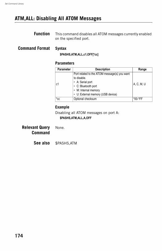
Set Command Library
ATM,ALL: Disabling All ATOM Messages
Function This command disables all ATOM messages currently enabled on the specified port.
Command Format Syntax$PASHS,ATM,ALL,c1,OFF[*cc]
Parameters
ExampleDisabling all ATOM messages on port A:
$PASHS,ATM,ALL,A,OFF
Relevant QueryCommand
None.
See also $PASHS,ATM
Parameter Description Range
c1
Port related to the ATOM message(s) you want to disable.• A: Serial port• C: Bluetooth port• M: Internal memory• U: External memory (USB device)
A, C, M, U
*cc Optional checksum *00-*FF
174
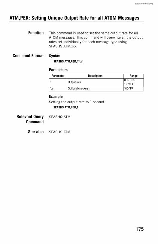
Set Command Library
ATM,PER: Setting Unique Output Rate for all ATOM Messages
Function This command is used to set the same output rate for all ATOM messages. This command will overwrite all the output rates set individually for each message type using $PASHS,ATM,xxx.
Command Format Syntax$PASHS,ATM,PER,f[*cc]
Parameters
ExampleSetting the output rate to 1 second:
$PASHS,ATM,PER,1
Relevant QueryCommand
$PASHQ,ATM
See also $PASHS,ATM
Parameter Description Range
f Output rate 0.1-0.9 s1-999 s
*cc Optional checksum *00-*FF
175
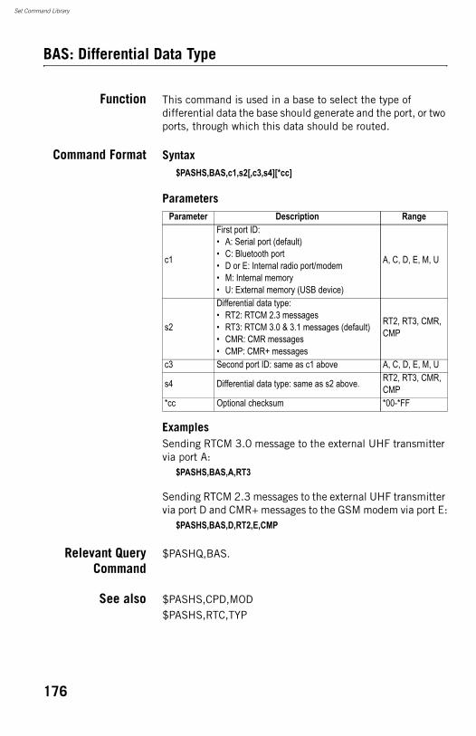
Set Command Library
BAS: Differential Data Type
Function This command is used in a base to select the type of differential data the base should generate and the port, or two ports, through which this data should be routed.
Command Format Syntax$PASHS,BAS,c1,s2[,c3,s4][*cc]
Parameters
ExamplesSending RTCM 3.0 message to the external UHF transmitter via port A:
$PASHS,BAS,A,RT3
Sending RTCM 2.3 messages to the external UHF transmitter via port D and CMR+ messages to the GSM modem via port E:
$PASHS,BAS,D,RT2,E,CMP
Relevant QueryCommand
$PASHQ,BAS.
See also $PASHS,CPD,MOD$PASHS,RTC,TYP
Parameter Description Range
c1
First port ID:• A: Serial port (default)• C: Bluetooth port• D or E: Internal radio port/modem• M: Internal memory• U: External memory (USB device)
A, C, D, E, M, U
s2
Differential data type:• RT2: RTCM 2.3 messages• RT3: RTCM 3.0 & 3.1 messages (default)• CMR: CMR messages• CMP: CMR+ messages
RT2, RT3, CMR, CMP
c3 Second port ID: same as c1 above A, C, D, E, M, U
s4 Differential data type: same as s2 above. RT2, RT3, CMR, CMP
*cc Optional checksum *00-*FF
176
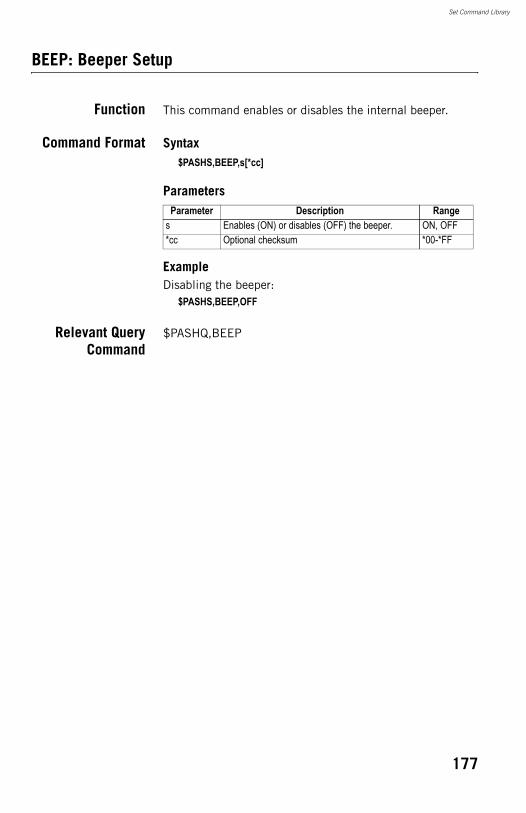
Set Command Library
BEEP: Beeper Setup
Function This command enables or disables the internal beeper.
Command Format Syntax$PASHS,BEEP,s[*cc]
Parameters
ExampleDisabling the beeper:
$PASHS,BEEP,OFF
Relevant QueryCommand
$PASHQ,BEEP
Parameter Description Ranges Enables (ON) or disables (OFF) the beeper. ON, OFF*cc Optional checksum *00-*FF
177
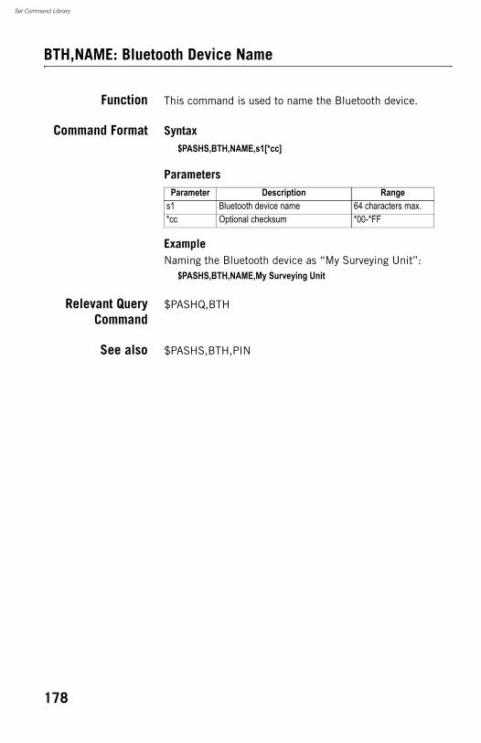
Set Command Library
BTH,NAME: Bluetooth Device Name
Function This command is used to name the Bluetooth device.
Command Format Syntax$PASHS,BTH,NAME,s1[*cc]
Parameters
ExampleNaming the Bluetooth device as “My Surveying Unit”:
$PASHS,BTH,NAME,My Surveying Unit
Relevant QueryCommand
$PASHQ,BTH
See also $PASHS,BTH,PIN
Parameter Description Ranges1 Bluetooth device name 64 characters max.*cc Optional checksum *00-*FF
178
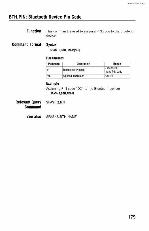
Set Command Library
BTH,PIN: Bluetooth Device Pin Code
Function This command is used to assign a PIN code to the Bluetooth device.
Command Format Syntax$PASHS,BTH,PIN,d1[*cc]
Parameters
ExampleAssigning PIN code “02” to the Bluetooth device:
$PASHS,BTH,PIN,02
Relevant QueryCommand
$PASHQ,BTH
See also $PASHS,BTH,NAME
Parameter Description Range
d1 Bluetooth PIN code 0-99999999-1: no PIN code
*cc Optional checksum *00-*FF
179
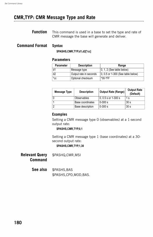
Set Command Library
CMR,TYP: CMR Message Type and Rate
Function This command is used in a base to set the type and rate of CMR message the base will generate and deliver.
Command Format Syntax$PASHS,CMR,TYP,d1,d2[*cc]
Parameters
ExamplesSetting a CMR message type 0 (observables) at a 1-second output rate:
$PASHS,CMR,TYP,0,1
Setting a CMR message type 1 (base coordinates) at a 30-second output rate:
$PASHS,CMR,TYP,1,30
Relevant QueryCommand
$PASHQ,CMR,MSI
See also $PASHS,BAS$PASHS,CPD,MOD,BAS.
Parameter Description Ranged1 Message type 0, 1, 2 (See table below)d2 Output rate in seconds 0, 0.5 or 1-300 (See table below)*cc Optional checksum *00-*FF
Message Type Description Output Rate (Range) Output Rate (Default)
0 Observables 0, 0.5 s or 1-300 s 1 s1 Base coordinates 0-300 s 30 s2 Base description 0-300 s 30 s
180
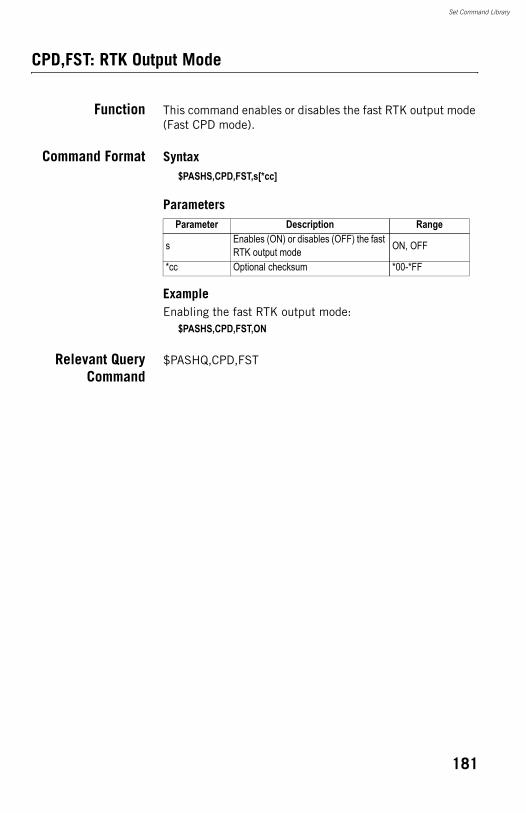
Set Command Library
CPD,FST: RTK Output Mode
Function This command enables or disables the fast RTK output mode (Fast CPD mode).
Command Format Syntax$PASHS,CPD,FST,s[*cc]
Parameters
ExampleEnabling the fast RTK output mode:
$PASHS,CPD,FST,ON
Relevant QueryCommand
$PASHQ,CPD,FST
Parameter Description Range
s Enables (ON) or disables (OFF) the fast RTK output mode ON, OFF
*cc Optional checksum *00-*FF
181
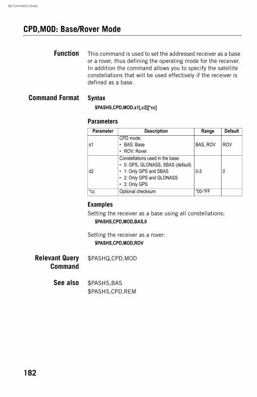
Set Command Library
CPD,MOD: Base/Rover Mode
Function This command is used to set the addressed receiver as a base or a rover, thus defining the operating mode for the receiver. In addition the command allows you to specify the satellite constellations that will be used effectively if the receiver is defined as a base.
Command Format Syntax$PASHS,CPD,MOD,s1[,c2][*cc]
Parameters
ExamplesSetting the receiver as a base using all constellations:
$PASHS,CPD,MOD,BAS,0
Setting the receiver as a rover:$PASHS,CPD,MOD,ROV
Relevant QueryCommand
$PASHQ,CPD,MOD
See also $PASHS,BAS$PASHS,CPD,REM
Parameter Description Range Default
s1CPD mode:• BAS: Base• ROV: Rover
BAS, ROV ROV
d2
Constellations used in the base:• 0: GPS, GLONASS, SBAS (default)• 1: Only GPS and SBAS• 2: Only GPS and GLONASS• 3: Only GPS
0-3 0
*cc Optional checksum *00-*FF
182
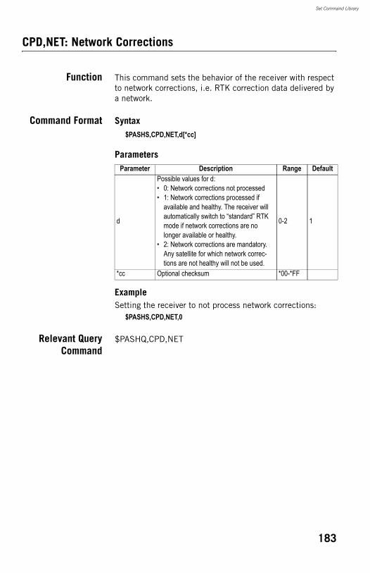
Set Command Library
CPD,NET: Network Corrections
Function This command sets the behavior of the receiver with respect to network corrections, i.e. RTK correction data delivered by a network.
Command Format Syntax$PASHS,CPD,NET,d[*cc]
Parameters
ExampleSetting the receiver to not process network corrections:
$PASHS,CPD,NET,0
Relevant QueryCommand
$PASHQ,CPD,NET
Parameter Description Range Default
d
Possible values for d:• 0: Network corrections not processed• 1: Network corrections processed if
available and healthy. The receiver will automatically switch to “standard” RTK mode if network corrections are no longer available or healthy.
• 2: Network corrections are mandatory. Any satellite for which network correc-tions are not healthy will not be used.
0-2 1
*cc Optional checksum *00-*FF
183
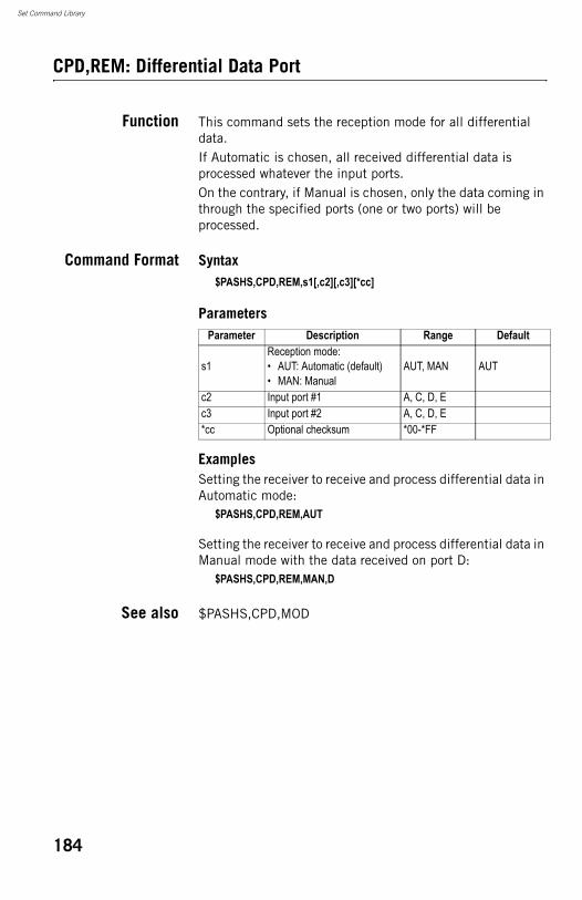
Set Command Library
CPD,REM: Differential Data Port
Function This command sets the reception mode for all differential data.If Automatic is chosen, all received differential data is processed whatever the input ports.On the contrary, if Manual is chosen, only the data coming in through the specified ports (one or two ports) will be processed.
Command Format Syntax$PASHS,CPD,REM,s1[,c2][,c3][*cc]
Parameters
ExamplesSetting the receiver to receive and process differential data in Automatic mode:
$PASHS,CPD,REM,AUT
Setting the receiver to receive and process differential data in Manual mode with the data received on port D:
$PASHS,CPD,REM,MAN,D
See also $PASHS,CPD,MOD
Parameter Description Range Default
s1Reception mode:• AUT: Automatic (default)• MAN: Manual
AUT, MAN AUT
c2 Input port #1 A, C, D, Ec3 Input port #2 A, C, D, E*cc Optional checksum *00-*FF
184
Set Command Library
CPD,RST: RTK Process Reset
Function This command resets the RTK processing.
Command Format Syntax$PASHS,CPD,RST[*cc]
ParametersNone
ExampleResetting the RTK processing:
$PASHS,CPD,RST
Relevant QueryCommand
None.
185
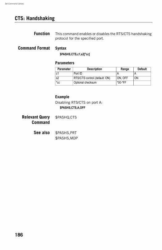
Set Command Library
CTS: Handshaking
Function This command enables or disables the RTS/CTS handshaking protocol for the specified port.
Command Format Syntax$PASHS,CTS,c1,s2[*cc]
Parameters
ExampleDisabling RTS/CTS on port A:
$PASHS,CTS,A,OFF
Relevant QueryCommand
$PASHQ,CTS
See also $PASHS,PRT$PASHS,MDP
Parameter Description Range Defaultc1 Port ID A As2 RTS/CTS control (default: ON) ON, OFF ON*cc Optional checksum *00-*FF
186
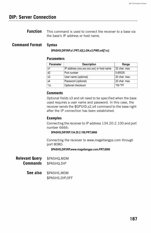
Set Command Library
DIP: Server Connection
Function This command is used to connect the receiver to a base via the base’s IP address or host name.
Command Format Syntax$PASHS,DIP,RIP,s1,PRT,d2[,LGN,s3,PWD,s4][*cc]
Parameters
CommentsOptional fields s3 and s4 need to be specified when the base used requires a user name and password. In this case, the receiver sends the $GPUID,s2,s4 command to the base right after the IP connection has been established.
ExamplesConnecting the receiver to IP address 134.20.2.100 and port number 6666:
$PASHS,DIP,RIP,134.20.2.100,PRT,6666
Connecting the receiver to www.magellangps.com through port 8080:
$PASHS,DIP,RIP,www.magellangps.com,PRT,8080
Relevant QueryCommands
$PASHQ,MDM$PASHQ,DIP
See also $PASHS,MDM$PASHS,DIP,OFF
Parameter Description Ranges1 IP address (xxx.xxx.xxx.xxx) or host name 32 char. max.d2 Port number 0-65535s3 User name (optional) 20 char. max.s4 Password (optional) 20 char. max.*cc Optional checksum *00-*FF
187
Set Command Library
DIP,OFF: Terminating Direct IP Connection
Function This command is used to terminate the current connection to a base via the base’s IP address or host name.
Command Format Syntax$PASHS,DIP,OFF[*cc]
ParametersNone.
ExamplesTerminating the current connection:
$PASHS,DIP,OFF
Relevant QueryCommand
$PASHQ,MDM
See also $PASHS,DIP
188
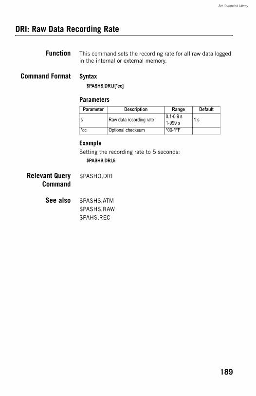
Set Command Library
DRI: Raw Data Recording Rate
Function This command sets the recording rate for all raw data logged in the internal or external memory.
Command Format Syntax$PASHS,DRI,f[*cc]
Parameters
ExampleSetting the recording rate to 5 seconds:
$PASHS,DRI,5
Relevant QueryCommand
$PASHQ,DRI
See also $PASHS,ATM$PASHS,RAW$PAHS,REC
Parameter Description Range Default
s Raw data recording rate 0.1-0.9 s1-999 s 1 s
*cc Optional checksum *00-*FF
189
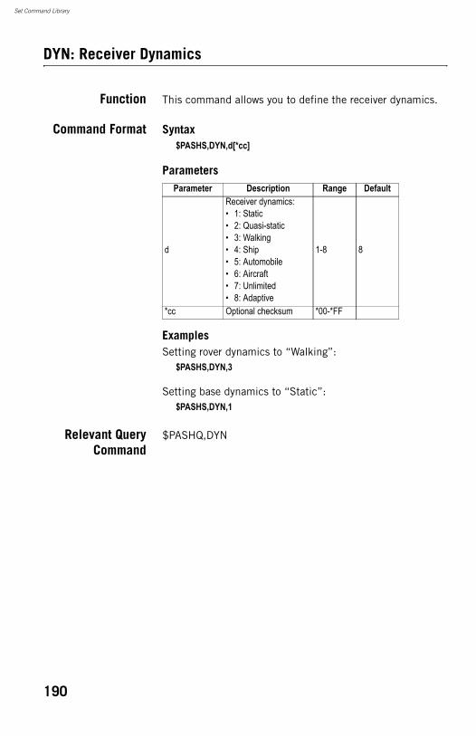
Set Command Library
DYN: Receiver Dynamics
Function This command allows you to define the receiver dynamics.
Command Format Syntax$PASHS,DYN,d[*cc]
Parameters
ExamplesSetting rover dynamics to “Walking”:
$PASHS,DYN,3
Setting base dynamics to “Static”:$PASHS,DYN,1
Relevant QueryCommand
$PASHQ,DYN
Parameter Description Range Default
d
Receiver dynamics:• 1: Static• 2: Quasi-static• 3: Walking• 4: Ship• 5: Automobile• 6: Aircraft• 7: Unlimited• 8: Adaptive
1-8 8
*cc Optional checksum *00-*FF
190
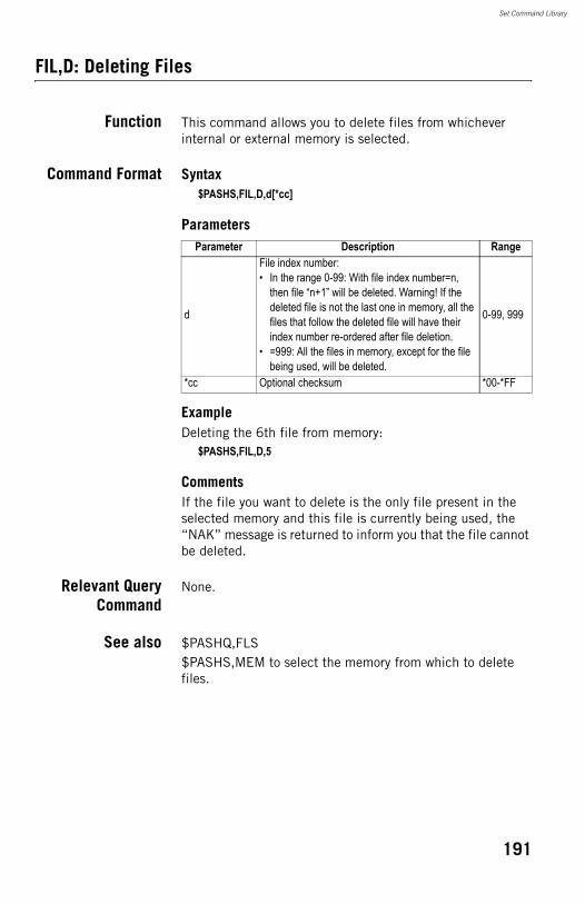
Set Command Library
FIL,D: Deleting Files
Function This command allows you to delete files from whichever internal or external memory is selected.
Command Format Syntax$PASHS,FIL,D,d[*cc]
Parameters
ExampleDeleting the 6th file from memory:
$PASHS,FIL,D,5
CommentsIf the file you want to delete is the only file present in the selected memory and this file is currently being used, the “NAK” message is returned to inform you that the file cannot be deleted.
Relevant QueryCommand
None.
See also $PASHQ,FLS$PASHS,MEM to select the memory from which to delete files.
Parameter Description Range
d
File index number:• In the range 0-99: With file index number=n,
then file “n+1” will be deleted. Warning! If the deleted file is not the last one in memory, all the files that follow the deleted file will have their index number re-ordered after file deletion.
• =999: All the files in memory, except for the file being used, will be deleted.
0-99, 999
*cc Optional checksum *00-*FF
191
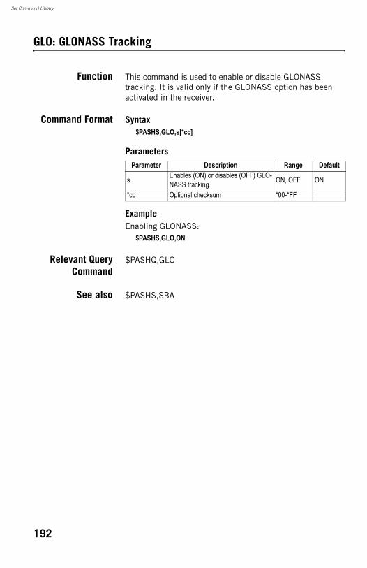
Set Command Library
GLO: GLONASS Tracking
Function This command is used to enable or disable GLONASS tracking. It is valid only if the GLONASS option has been activated in the receiver.
Command Format Syntax$PASHS,GLO,s[*cc]
Parameters
ExampleEnabling GLONASS:
$PASHS,GLO,ON
Relevant QueryCommand
$PASHQ,GLO
See also $PASHS,SBA
Parameter Description Range Default
s Enables (ON) or disables (OFF) GLO-NASS tracking. ON, OFF ON
*cc Optional checksum *00-*FF
192
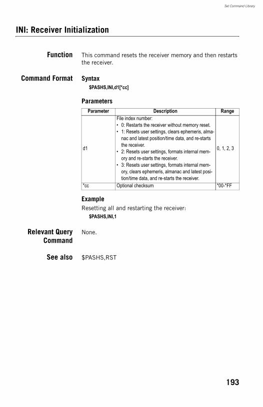
Set Command Library
INI: Receiver Initialization
Function This command resets the receiver memory and then restarts the receiver.
Command Format Syntax$PASHS,INI,d1[*cc]
Parameters
ExampleResetting all and restarting the receiver:
$PASHS,INI,1
Relevant QueryCommand
None.
See also $PASHS,RST
Parameter Description Range
d1
File index number:• 0: Restarts the receiver without memory reset.• 1: Resets user settings, clears ephemeris, alma-
nac and latest position/time data, and re-starts the receiver.
• 2: Resets user settings, formats internal mem-ory and re-starts the receiver.
• 3: Resets user settings, formats internal mem-ory, clears ephemeris, almanac and latest posi-tion/time data, and re-starts the receiver.
0, 1, 2, 3
*cc Optional checksum *00-*FF
193
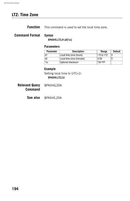
Set Command Library
LTZ: Time Zone
Function This command is used to set the local time zone.
Command Format Syntax$PASHS,LTZ,d1,d2[*cc]
Parameters
ExampleSetting local time to UTC+2:
$PASHS,LTZ,2,0
Relevant QueryCommand
$PASHQ,ZDA
See also $PASHS,ZDA
Parameter Description Range Defaultd1 Local time zone (hours). -13 to +13 0d2 Local time zone (minutes) 0-59 0*cc Optional checksum *00-*FF
194
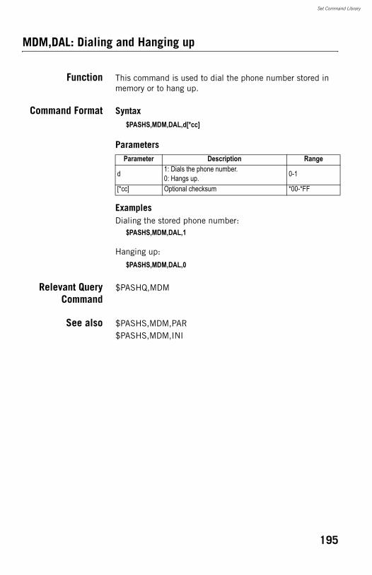
Set Command Library
MDM,DAL: Dialing and Hanging up
Function This command is used to dial the phone number stored in memory or to hang up.
Command Format Syntax$PASHS,MDM,DAL,d[*cc]
Parameters
ExamplesDialing the stored phone number:
$PASHS,MDM,DAL,1
Hanging up:
$PASHS,MDM,DAL,0
Relevant QueryCommand
$PASHQ,MDM
See also $PASHS,MDM,PAR$PASHS,MDM,INI
Parameter Description Range
d 1: Dials the phone number.0: Hangs up. 0-1
[*cc] Optional checksum *00-*FF
195
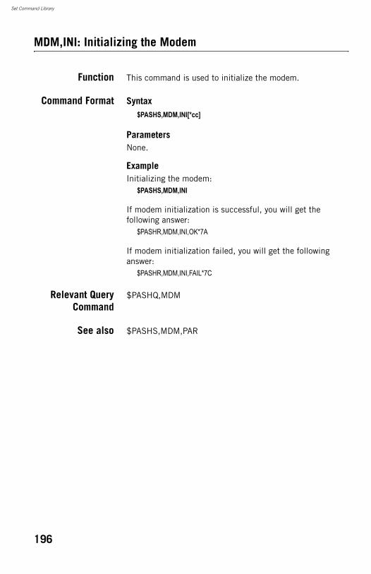
Set Command Library
MDM,INI: Initializing the Modem
Function This command is used to initialize the modem.
Command Format Syntax$PASHS,MDM,INI[*cc]
ParametersNone.
ExampleInitializing the modem:
$PASHS,MDM,INI
If modem initialization is successful, you will get the following answer:
$PASHR,MDM,INI,OK*7A
If modem initialization failed, you will get the following answer:
$PASHR,MDM,INI,FAIL*7C
Relevant QueryCommand
$PASHQ,MDM
See also $PASHS,MDM,PAR
196
Set Command Library
MDM,OFF: Powering Off the Internal Modem
Function This command is used to power off the internal modem.
Command Format Syntax$PASHS,MDM,OFF[*cc]
ParametersNone.
ExampleTurning off the internal modem:
$PASHS,MDM,OFF
Relevant QueryCommand
$PASHQ,MDM
See also $PASHS,MDM,ON
197
Set Command Library
MDM,ON: Powering On the Internal Modem
Function This command is used to power on the internal modem.
Command Format Syntax$PASHS,MDM,ON[*cc]
ParametersNone.
ExampleTurning on the internal modem:
$PASHS,MDM,ON
Relevant QueryCommand
$PASHQ,MDM
See also $PASHS,MDM,OFF
198
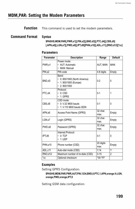
Set Command Library
MDM,PAR: Setting the Modem Parameters
Function This command is used to set the modem parameters.
Command Format Syntax$PASHS,MDM,PAR[,PWR,s1][,PIN,s2][,BND,d3][,PTC,d4][,CBS,d5][,APN,s6][,LGN,s7][,PWD,s8][,IPT,d9][PHN,s10][,ADL,c11],[RNO,d12][*cc]
Parameters
ExamplesSetting GPRS Configuration:
$PASHS,MDM,PAR,PWR,AUT,PIN,1234,BND,0,PTC,1,APN,orange.fr,LGN,orange,PWD,orange,IPT,0
Setting GSM data configuration:
Parameter Description Range Default
PWR,s1Power mode:• AUT: Automatic• MAN: Manual
AUT, MAN MAN
PIN,s2 PIN code 4-8 digits Empty
BND,d3
Band:• 0: 850/1900 (North America)• 1: 900/1800 (Europe)• 2: 900/1900
0-2 0
PTC,d4Protocol:• 0: CSD• 1: GPRS
0-1 1
CBS,d5CSD mode:• 0: V.32 9600 bauds• 1: V.110 9600 bauds ISDN
0-1 0
APN,s6 Access Point Name (GPRS) 32 char. max. Empty
LGN,s7 Login (GPRS) 32 char. max. Empty
PWD,s8 Password (GPRS) 32 char. max. Empty
IPT,d9Internet Protocol:• 0: TCP• 1: UDP
0-1 0
PHN,s10 Phone number (CSD) 20 digits max. Empty
ADL,c11 Auto-dial mode (CSD) Y, N YRNO,d12 Maximum number of re-dials (CSD) 0-15 2*cc Optional checksum *00-*FF
199
Set Command Library
$PASHS,MDM,PAR,PWR,AUT,PIN,1234,BND,1,PTC,0,CBS,1,PHN,0228093838,ADL,Y,RNO,5
Relevant QueryCommand
$PASHQ,MDM
See also $PASHS,DAL$PASHS,DIP$PASHS,NTR$PASHS,MWD
200
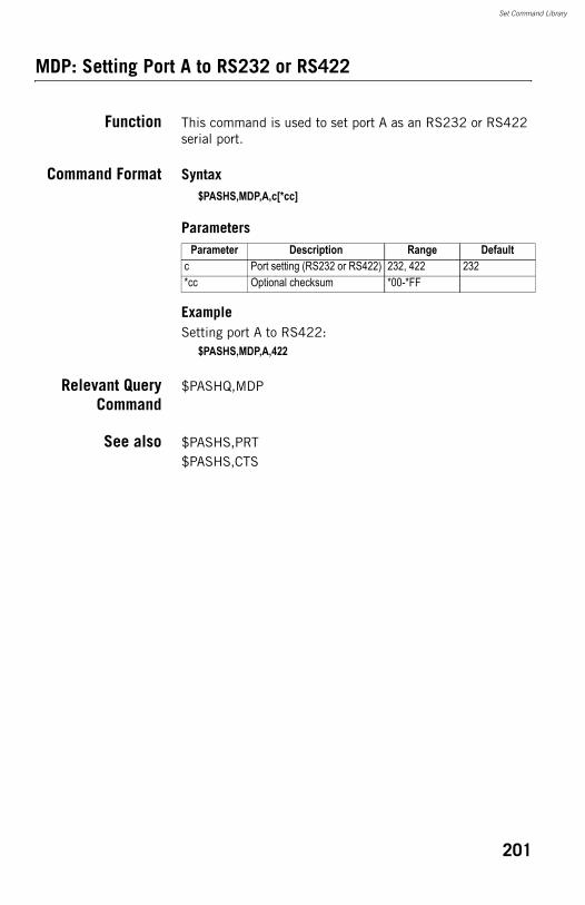
Set Command Library
MDP: Setting Port A to RS232 or RS422
Function This command is used to set port A as an RS232 or RS422 serial port.
Command Format Syntax$PASHS,MDP,A,c[*cc]
Parameters
ExampleSetting port A to RS422:
$PASHS,MDP,A,422
Relevant QueryCommand
$PASHQ,MDP
See also $PASHS,PRT$PASHS,CTS
Parameter Description Range Defaultc Port setting (RS232 or RS422) 232, 422 232*cc Optional checksum *00-*FF
201
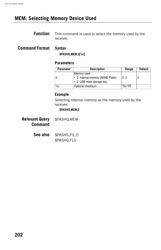
Set Command Library
MEM: Selecting Memory Device Used
Function This command is used to select the memory used by the receiver.
Command Format Syntax$PASHS,MEM,d[*cc]
Parameters
ExampleSelecting internal memory as the memory used by the receiver:
$PASHS,MEM,0
Relevant QueryCommand
$PASHQ,MEM
See also $PASHS,FIL,D$PASHQ,FLS
Parameter Description Range Default
dMemory used:• 0: Internal memory (NAND Flash)• 2: USB mass storage key
0, 2 0
*cc Optional checksum *00-*FF
202
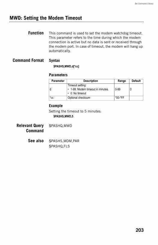
Set Command Library
MWD: Setting the Modem Timeout
Function This command is used to set the modem watchdog timeout. This parameter refers to the time during which the modem connection is active but no data is sent or received through the modem port. In case of timeout, the modem will hang up automatically.
Command Format Syntax$PASHS,MWD,d[*cc]
Parameters
ExampleSetting the timeout to 5 minutes:
$PASHS,MWD,5
Relevant QueryCommand
$PASHQ,MWD
See also $PASHS,MDM,PAR$PASHQ,FLS
Parameter Description Range Default
dTimeout setting:• 1-99: Modem timeout in minutes.• 0: No timeout
0-99 0
*cc Optional checksum *00-*FF
203
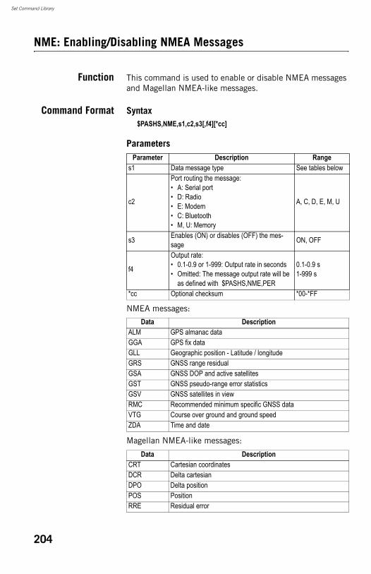
Set Command Library
NME: Enabling/Disabling NMEA Messages
Function This command is used to enable or disable NMEA messages and Magellan NMEA-like messages.
Command Format Syntax$PASHS,NME,s1,c2,s3[,f4][*cc]
Parameters
NMEA messages:
Magellan NMEA-like messages:
Parameter Description Ranges1 Data message type See tables below
c2
Port routing the message:• A: Serial port• D: Radio• E: Modem• C: Bluetooth• M, U: Memory
A, C, D, E, M, U
s3 Enables (ON) or disables (OFF) the mes-sage ON, OFF
f4
Output rate:• 0.1-0.9 or 1-999: Output rate in seconds• Omitted: The message output rate will be
as defined with $PASHS,NME,PER
0.1-0.9 s1-999 s
*cc Optional checksum *00-*FF
Data DescriptionALM GPS almanac dataGGA GPS fix dataGLL Geographic position - Latitude / longitudeGRS GNSS range residualGSA GNSS DOP and active satellitesGST GNSS pseudo-range error statisticsGSV GNSS satellites in viewRMC Recommended minimum specific GNSS dataVTG Course over ground and ground speedZDA Time and date
Data DescriptionCRT Cartesian coordinatesDCR Delta cartesianDPO Delta positionPOS PositionRRE Residual error
204

Set Command Library
ExampleSetting GGA message on Bluetooth port at 1-second output rate:
$PASHS,NME,GGA,C,ON,1
Relevant QueryCommand
$PASHQ,NMO
See also $PASHS,NME,PER
SAT Satellite statusVEC Vector and accuracy
Data Description
205
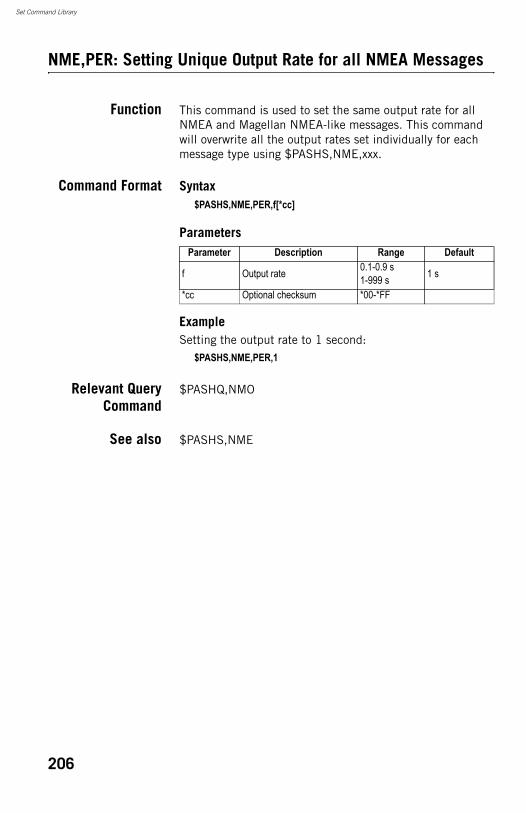
Set Command Library
NME,PER: Setting Unique Output Rate for all NMEA Messages
Function This command is used to set the same output rate for all NMEA and Magellan NMEA-like messages. This command will overwrite all the output rates set individually for each message type using $PASHS,NME,xxx.
Command Format Syntax$PASHS,NME,PER,f[*cc]
Parameters
ExampleSetting the output rate to 1 second:
$PASHS,NME,PER,1
Relevant QueryCommand
$PASHQ,NMO
See also $PASHS,NME
Parameter Description Range Default
f Output rate 0.1-0.9 s1-999 s 1 s
*cc Optional checksum *00-*FF
206
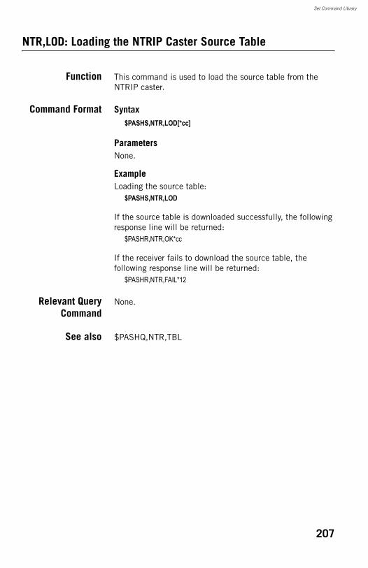
Set Command Library
NTR,LOD: Loading the NTRIP Caster Source Table
Function This command is used to load the source table from the NTRIP caster.
Command Format Syntax$PASHS,NTR,LOD[*cc]
ParametersNone.
ExampleLoading the source table:
$PASHS,NTR,LOD
If the source table is downloaded successfully, the following response line will be returned:
$PASHR,NTR,OK*cc
If the receiver fails to download the source table, the following response line will be returned:
$PASHR,NTR,FAIL*12
Relevant QueryCommand
None.
See also $PASHQ,NTR,TBL
207
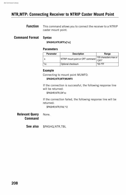
Set Command Library
NTR,MTP: Connecting Receiver to NTRIP Caster Mount Point
Function This command allows you to connect the receiver to a NTRIP caster mount point.
Command Format Syntax$PASHS,NTR,MTP,s[*cc]
Parameters
ExampleConnecting to mount point MUWF0:
$PASHS,NTR,MTP,MUWF0
If the connection is successful, the following response line will be returned:
$PASHR,NTR,OK*cc
If the connection failed, the following response line will be returned:
$PASHR,NTR,FAIL*12
Relevant QueryCommand
None.
See also $PASHQ,NTR,TBL
Parameter Description Range
s NTRIP mount point or OFF command 100 characters max or “OFF”
*cc Optional checksum *00-*FF
208
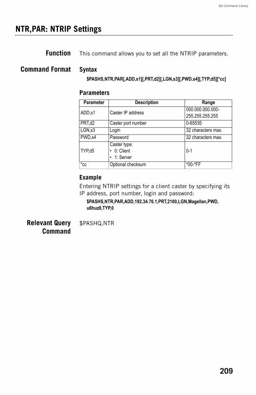
Set Command Library
NTR,PAR: NTRIP Settings
Function This command allows you to set all the NTRIP parameters.
Command Format Syntax$PASHS,NTR,PAR[,ADD,s1][,PRT,d2][,LGN,s3][,PWD,s4][,TYP,d5][*cc]
Parameters
ExampleEntering NTRIP settings for a client caster by specifying its IP address, port number, login and password:
$PASHS,NTR,PAR,ADD,192.34.76.1,PRT,2100,LGN,Magellan,PWD,u6huz8,TYP,0
Relevant QueryCommand
$PASHQ,NTR
Parameter Description Range
ADD,s1 Caster IP address 000.000.000.000-255.255.255.255
PRT,d2 Caster port number 0-65535LGN,s3 Login 32 characters max.PWD,s4 Password 32 characters max.
TYP,d5Caster type:• 0: Client• 1: Server
0-1
*cc Optional checksum *00-*FF
209
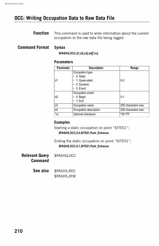
Set Command Library
OCC: Writing Occupation Data to Raw Data File
Function This command is used to write information about the current occupation to the raw data file being logged.
Command Format Syntax$PASHS,OCC,d1,d2,s3[,s4][*cc]
Parameters
ExamplesStarting a static occupation on point “SITE01”:
$PASHS,OCC,0,0,SITE01,Park_Entrance
Ending the static occupation on point “SITE01”:$PASHS,OCC,0,1,SITE01,Park_Entrance
Relevant QueryCommand
$PASHQ,OCC
See also $PASHS,REC$PASHS,ATM
Parameter Description Range
d1
Occupation type:• 0: Static• 1: Quasi-static• 2: Dynamic• 3: Event
0-3
d2Occupation event:• 0: Begin• 1: End
0-1
s3 Occupation name 255 characters max.s4 Occupation description 255 characters max.*cc Optional checksum *00-*FF
210
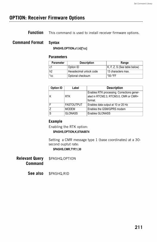
Set Command Library
OPTION: Receiver Firmware Options
Function This command is used to install receiver firmware options.
Command Format Syntax$PASHS,OPTION,c1,h2[*cc]
Parameters
ExampleEnabling the RTK option:
$PASHS,OPTION,K,878A8874
Setting a CMR message type 1 (base coordinates) at a 30-second ouptut rate:
$PASHS,CMR,TYP,1,30
Relevant QueryCommand
$PASHQ,OPTION
See also $PASHQ,RID
Parameter Description Rangec1 Option ID K, F, Z, S (See table below)h2 Hexadecimal unlock code 13 characters max.*cc Optional checksum *00-*FF
Option ID Label Description
K RTKEnables RTK processing. Corrections gener-ated in RTCM2.3, RTCM3.0, CMR or CMR+ format.
F FASTOUTPUT Enables data output at 10 or 20 HzZ MODEM Enables the GSM/GPRS modemS GLONASS Enables GLONASS
211
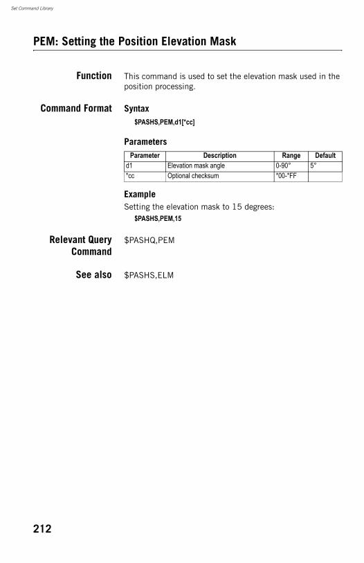
Set Command Library
PEM: Setting the Position Elevation Mask
Function This command is used to set the elevation mask used in the position processing.
Command Format Syntax$PASHS,PEM,d1[*cc]
Parameters
ExampleSetting the elevation mask to 15 degrees:
$PASHS,PEM,15
Relevant QueryCommand
$PASHQ,PEM
See also $PASHS,ELM
Parameter Description Range Defaultd1 Elevation mask angle 0-90° 5°*cc Optional checksum *00-*FF
212
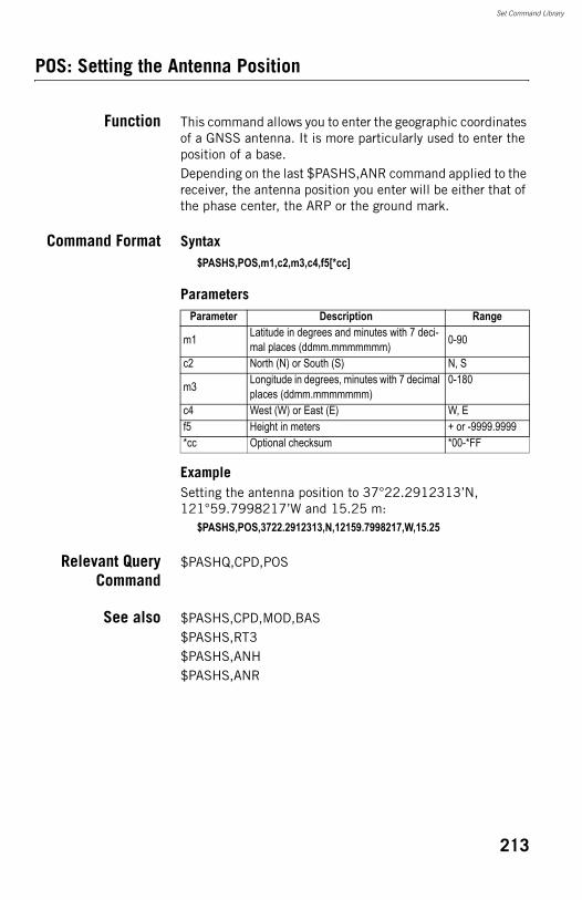
Set Command Library
POS: Setting the Antenna Position
Function This command allows you to enter the geographic coordinates of a GNSS antenna. It is more particularly used to enter the position of a base.Depending on the last $PASHS,ANR command applied to the receiver, the antenna position you enter will be either that of the phase center, the ARP or the ground mark.
Command Format Syntax$PASHS,POS,m1,c2,m3,c4,f5[*cc]
Parameters
ExampleSetting the antenna position to 37°22.2912313’N, 121°59.7998217’W and 15.25 m:
$PASHS,POS,3722.2912313,N,12159.7998217,W,15.25
Relevant QueryCommand
$PASHQ,CPD,POS
See also $PASHS,CPD,MOD,BAS$PASHS,RT3$PASHS,ANH$PASHS,ANR
Parameter Description Range
m1 Latitude in degrees and minutes with 7 deci-mal places (ddmm.mmmmmmm) 0-90
c2 North (N) or South (S) N, S
m3 Longitude in degrees, minutes with 7 decimal places (ddmm.mmmmmmm)
0-180
c4 West (W) or East (E) W, Ef5 Height in meters + or -9999.9999*cc Optional checksum *00-*FF
213
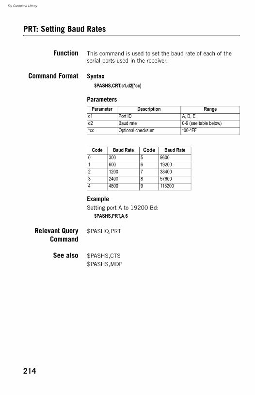
Set Command Library
PRT: Setting Baud Rates
Function This command is used to set the baud rate of each of the serial ports used in the receiver.
Command Format Syntax$PASHS,CRT,c1,d2[*cc]
Parameters
ExampleSetting port A to 19200 Bd:
$PASHS,PRT,A,6
Relevant QueryCommand
$PASHQ,PRT
See also $PASHS,CTS$PASHS,MDP
Parameter Description Rangec1 Port ID A, D, Ed2 Baud rate 0-9 (see table below)*cc Optional checksum *00-*FF
Code Baud Rate Code Baud Rate0 300 5 96001 600 6 192002 1200 7 384003 2400 8 576004 4800 9 115200
214
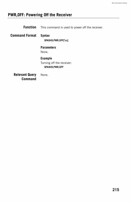
Set Command Library
PWR,OFF: Powering Off the Receiver
Function This command is used to power off the receiver.
Command Format Syntax$PASHS,PWR,OFF[*cc]
ParametersNone.
ExampleTurning off the receiver:
$PASHS,PWR,OFF
Relevant QueryCommand
None.
215
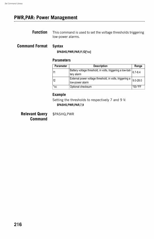
Set Command Library
PWR,PAR: Power Management
Function This command is used to set the voltage thresholds triggering low-power alarms.
Command Format Syntax$PASHS,PWR,PAR,f1,f2[*cc]
Parameters
ExampleSetting the thresholds to respectively 7 and 9 V:
$PASHS,PWR,PAR,7,9
Relevant QueryCommand
$PASHQ,PWR
Parameter Description Range
f1 Battery voltage threshold, in volts, triggering a low-bat-tery alarm 6.7-8.4
f2 External power voltage threshold, in volts, triggering a low-power alarm 9.0-28.0
*cc Optional checksum *00-*FF
216
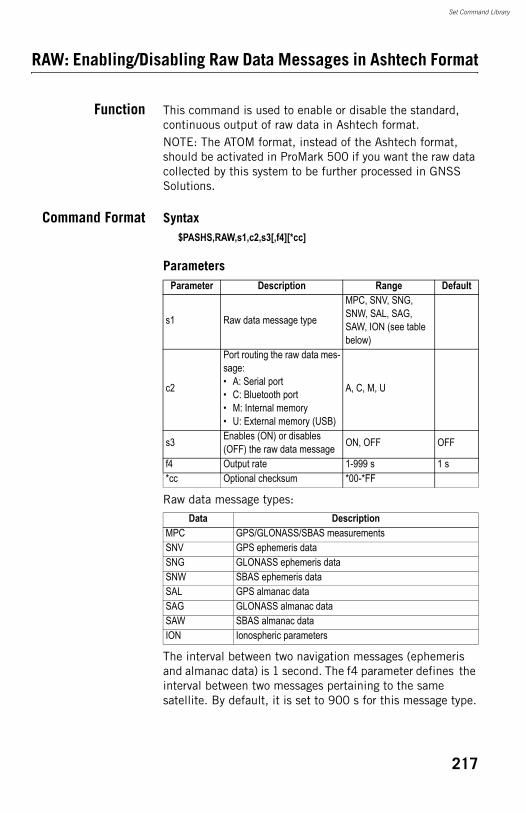
Set Command Library
RAW: Enabling/Disabling Raw Data Messages in Ashtech Format
Function This command is used to enable or disable the standard, continuous output of raw data in Ashtech format.NOTE: The ATOM format, instead of the Ashtech format, should be activated in ProMark 500 if you want the raw data collected by this system to be further processed in GNSS Solutions.
Command Format Syntax$PASHS,RAW,s1,c2,s3[,f4][*cc]
Parameters
Raw data message types:
The interval between two navigation messages (ephemeris and almanac data) is 1 second. The f4 parameter defines the interval between two messages pertaining to the same satellite. By default, it is set to 900 s for this message type.
Parameter Description Range Default
s1 Raw data message type
MPC, SNV, SNG, SNW, SAL, SAG, SAW, ION (see table below)
c2
Port routing the raw data mes-sage:• A: Serial port• C: Bluetooth port• M: Internal memory• U: External memory (USB)
A, C, M, U
s3 Enables (ON) or disables (OFF) the raw data message ON, OFF OFF
f4 Output rate 1-999 s 1 s*cc Optional checksum *00-*FF
Data DescriptionMPC GPS/GLONASS/SBAS measurementsSNV GPS ephemeris dataSNG GLONASS ephemeris dataSNW SBAS ephemeris dataSAL GPS almanac dataSAG GLONASS almanac dataSAW SBAS almanac dataION Ionospheric parameters
217
Set Command Library
ExampleEnabling output of MPC message type on port A to 1 second:
$PASHS,RAW,MPC,A,ON,1
Relevant QueryCommand
$PASHQ,RAW$PASHQ,RWO
See also $PASHS,RAW,PER$PASHS,RAW,ALL
218
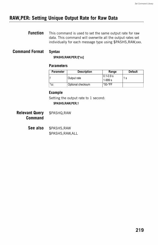
Set Command Library
RAW,PER: Setting Unique Output Rate for Raw Data
Function This command is used to set the same output rate for raw data. This command will overwrite all the output rates set individually for each message type using $PASHS,RAW,xxx.
Command Format Syntax$PASHS,RAW,PER,f[*cc]
Parameters
ExampleSetting the output rate to 1 second:
$PASHS,RAW,PER,1
Relevant QueryCommand
$PASHQ,RAW
See also $PASHS,RAW$PASHS,RAW,ALL
Parameter Description Range Default
f Output rate 0.1-0.9 s1-999 s 1 s
*cc Optional checksum *00-*FF
219
Set Command Library
RDP,OFF: Powering Off the Internal Radio
Function This command is used to power off the internal radio.
Command Format Syntax$PASHS,RDP,OFF[*cc]
ParametersNone.
ExampleTurning off the internal radio:
$PASHS,RDP,OFF
Relevant QueryCommand
$PASHQ,RDP,PAR,D
See also $PASHS,RDP,ON$PASHS,RDP,PAR
220
Set Command Library
RDP,ON: Powering On the Internal Radio
Function This command is used to power on the internal radio.
Command Format Syntax$PASHS,RDP,ON[*cc]
ParametersNone.
ExampleTurning on the internal radio:
$PASHS,RDP,ON
Relevant QueryCommand
$PASHQ,RDP,PAR,D
See also $PASHS,RDP,OFF$PASHS,RDP,PAR
221
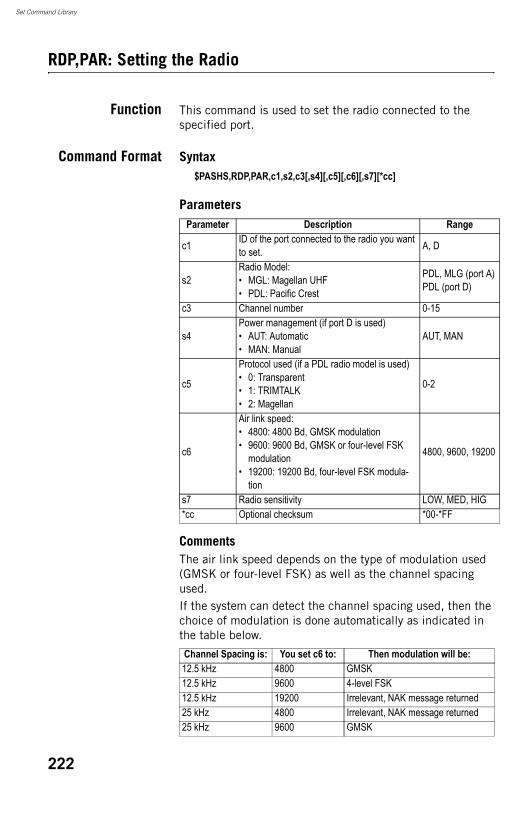
Set Command Library
RDP,PAR: Setting the Radio
Function This command is used to set the radio connected to the specified port.
Command Format Syntax$PASHS,RDP,PAR,c1,s2,c3[,s4][,c5][,c6][,s7][*cc]
Parameters
CommentsThe air link speed depends on the type of modulation used (GMSK or four-level FSK) as well as the channel spacing used.If the system can detect the channel spacing used, then the choice of modulation is done automatically as indicated in the table below.
Parameter Description Range
c1 ID of the port connected to the radio you want to set. A, D
s2Radio Model:• MGL: Magellan UHF• PDL: Pacific Crest
PDL, MLG (port A)PDL (port D)
c3 Channel number 0-15
s4Power management (if port D is used)• AUT: Automatic • MAN: Manual
AUT, MAN
c5
Protocol used (if a PDL radio model is used)• 0: Transparent • 1: TRIMTALK• 2: Magellan
0-2
c6
Air link speed:• 4800: 4800 Bd, GMSK modulation • 9600: 9600 Bd, GMSK or four-level FSK
modulation• 19200: 19200 Bd, four-level FSK modula-
tion
4800, 9600, 19200
s7 Radio sensitivity LOW, MED, HIG*cc Optional checksum *00-*FF
Channel Spacing is: You set c6 to: Then modulation will be:12.5 kHz 4800 GMSK12.5 kHz 9600 4-level FSK12.5 kHz 19200 Irrelevant, NAK message returned25 kHz 4800 Irrelevant, NAK message returned25 kHz 9600 GMSK
222
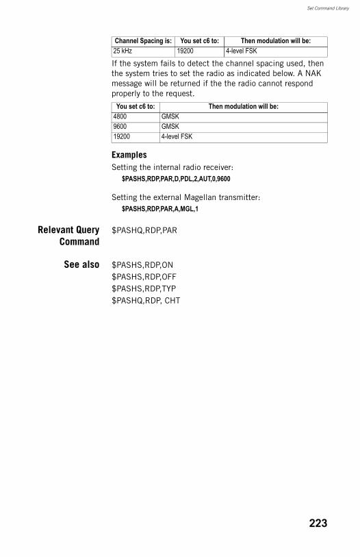
Set Command Library
If the system fails to detect the channel spacing used, then the system tries to set the radio as indicated below. A NAK message will be returned if the the radio cannot respond properly to the request.
ExamplesSetting the internal radio receiver:
$PASHS,RDP,PAR,D,PDL,2,AUT,0,9600
Setting the external Magellan transmitter:$PASHS,RDP,PAR,A,MGL,1
Relevant QueryCommand
$PASHQ,RDP,PAR
See also $PASHS,RDP,ON$PASHS,RDP,OFF$PASHS,RDP,TYP$PASHQ,RDP, CHT
25 kHz 19200 4-level FSK
You set c6 to: Then modulation will be:4800 GMSK9600 GMSK19200 4-level FSK
Channel Spacing is: You set c6 to: Then modulation will be:
223
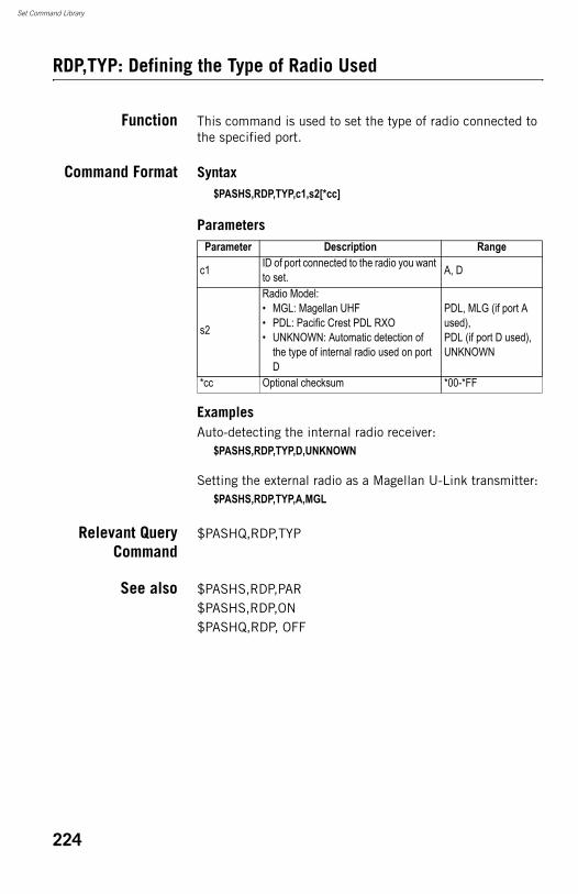
Set Command Library
RDP,TYP: Defining the Type of Radio Used
Function This command is used to set the type of radio connected to the specified port.
Command Format Syntax$PASHS,RDP,TYP,c1,s2[*cc]
Parameters
ExamplesAuto-detecting the internal radio receiver:
$PASHS,RDP,TYP,D,UNKNOWN
Setting the external radio as a Magellan U-Link transmitter:$PASHS,RDP,TYP,A,MGL
Relevant QueryCommand
$PASHQ,RDP,TYP
See also $PASHS,RDP,PAR$PASHS,RDP,ON$PASHQ,RDP, OFF
Parameter Description Range
c1 ID of port connected to the radio you want to set. A, D
s2
Radio Model:• MGL: Magellan UHF• PDL: Pacific Crest PDL RXO• UNKNOWN: Automatic detection of
the type of internal radio used on port D
PDL, MLG (if port A used),PDL (if port D used),UNKNOWN
*cc Optional checksum *00-*FF
224
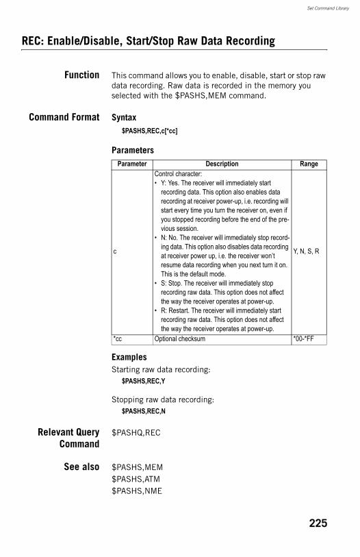
Set Command Library
REC: Enable/Disable, Start/Stop Raw Data Recording
Function This command allows you to enable, disable, start or stop raw data recording. Raw data is recorded in the memory you selected with the $PASHS,MEM command.
Command Format Syntax$PASHS,REC,c[*cc]
Parameters
ExamplesStarting raw data recording:
$PASHS,REC,Y
Stopping raw data recording:$PASHS,REC,N
Relevant QueryCommand
$PASHQ,REC
See also $PASHS,MEM$PASHS,ATM$PASHS,NME
Parameter Description Range
c
Control character:• Y: Yes. The receiver will immediately start
recording data. This option also enables data recording at receiver power-up, i.e. recording will start every time you turn the receiver on, even if you stopped recording before the end of the pre-vious session.
• N: No. The receiver will immediately stop record-ing data. This option also disables data recording at receiver power up, i.e. the receiver won’t resume data recording when you next turn it on. This is the default mode.
• S: Stop. The receiver will immediately stop recording raw data. This option does not affect the way the receiver operates at power-up.
• R: Restart. The receiver will immediately start recording raw data. This option does not affect the way the receiver operates at power-up.
Y, N, S, R
*cc Optional checksum *00-*FF
225
Set Command Library
RST: Default Settings
Function This command is used to reset the receiver parameters to their default values.
Command Format Syntax$PASHS,RST[*cc]
ParametersNone.
ExampleResetting the receiver:
$PASHS,RST
Relevant QueryCommand
None.
See also $PASHS,INI
226
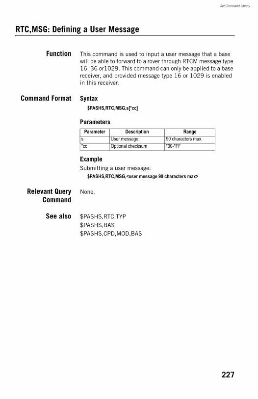
Set Command Library
RTC,MSG: Defining a User Message
Function This command is used to input a user message that a base will be able to forward to a rover through RTCM message type 16, 36 or1029. This command can only be applied to a base receiver, and provided message type 16 or 1029 is enabled in this receiver.
Command Format Syntax$PASHS,RTC,MSG,s[*cc]
Parameters
ExampleSubmitting a user message:
$PASHS,RTC,MSG,<user message 90 characters max>
Relevant QueryCommand
None.
See also $PASHS,RTC,TYP$PASHS,BAS$PASHS,CPD,MOD,BAS
Parameter Description Ranges User message 90 characters max.*cc Optional checksum *00-*FF
227
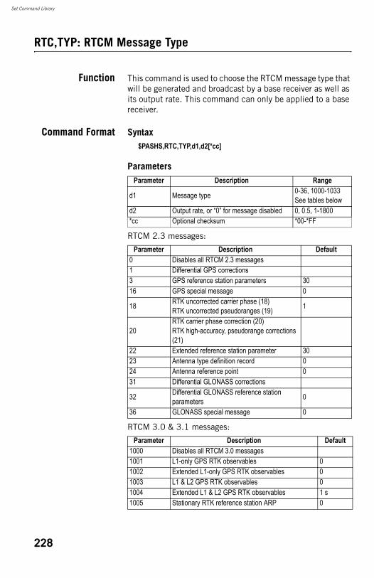
Set Command Library
RTC,TYP: RTCM Message Type
Function This command is used to choose the RTCM message type that will be generated and broadcast by a base receiver as well as its output rate. This command can only be applied to a base receiver.
Command Format Syntax$PASHS,RTC,TYP,d1,d2[*cc]
Parameters
RTCM 2.3 messages:
RTCM 3.0 & 3.1 messages:
Parameter Description Range
d1 Message type 0-36, 1000-1033See tables below
d2 Output rate, or “0” for message disabled 0, 0.5, 1-1800*cc Optional checksum *00-*FF
Parameter Description Default0 Disables all RTCM 2.3 messages1 Differential GPS corrections3 GPS reference station parameters 3016 GPS special message 0
18 RTK uncorrected carrier phase (18)RTK uncorrected pseudoranges (19) 1
20RTK carrier phase correction (20)RTK high-accuracy, pseudorange corrections (21)
22 Extended reference station parameter 3023 Antenna type definition record 024 Antenna reference point 031 Differential GLONASS corrections
32 Differential GLONASS reference station parameters 0
36 GLONASS special message 0
Parameter Description Default1000 Disables all RTCM 3.0 messages1001 L1-only GPS RTK observables 01002 Extended L1-only GPS RTK observables 01003 L1 & L2 GPS RTK observables 01004 Extended L1 & L2 GPS RTK observables 1 s1005 Stationary RTK reference station ARP 0
228
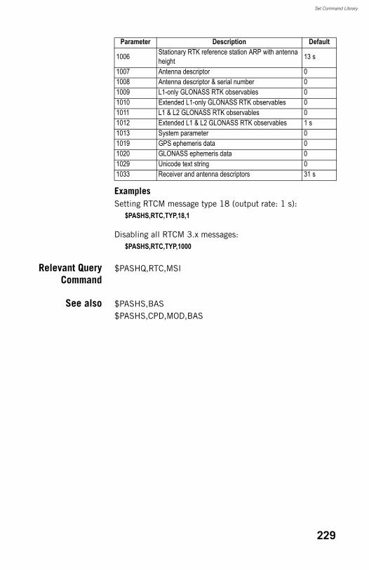
Set Command Library
ExamplesSetting RTCM message type 18 (output rate: 1 s):
$PASHS,RTC,TYP,18,1
Disabling all RTCM 3.x messages:$PASHS,RTC,TYP,1000
Relevant QueryCommand
$PASHQ,RTC,MSI
See also $PASHS,BAS$PASHS,CPD,MOD,BAS
1006 Stationary RTK reference station ARP with antenna height 13 s
1007 Antenna descriptor 01008 Antenna descriptor & serial number 01009 L1-only GLONASS RTK observables 01010 Extended L1-only GLONASS RTK observables 01011 L1 & L2 GLONASS RTK observables 01012 Extended L1 & L2 GLONASS RTK observables 1 s1013 System parameter 01019 GPS ephemeris data 01020 GLONASS ephemeris data 01029 Unicode text string 01033 Receiver and antenna descriptors 31 s
Parameter Description Default
229
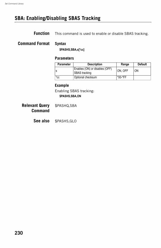
Set Command Library
SBA: Enabling/Disabling SBAS Tracking
Function This command is used to enable or disable SBAS tracking.
Command Format Syntax$PASHS,SBA,s[*cc]
Parameters
ExampleEnabling SBAS tracking:
$PASHS,SBA,ON
Relevant QueryCommand
$PASHQ,SBA
See also $PASHS,GLO
Parameter Description Range Default
s Enables (ON) or disables (OFF) SBAS tracking ON, OFF ON
*cc Optional checksum *00-*FF
230
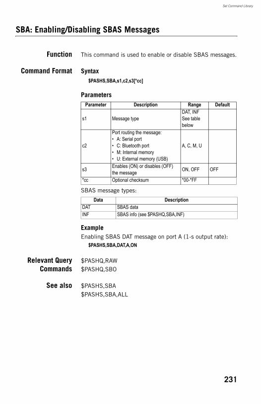
Set Command Library
SBA: Enabling/Disabling SBAS Messages
Function This command is used to enable or disable SBAS messages.
Command Format Syntax$PASHS,SBA,s1,c2,s3[*cc]
Parameters
SBAS message types:
ExampleEnabling SBAS DAT message on port A (1-s output rate):
$PASHS,SBA,DAT,A,ON
Relevant QueryCommands
$PASHQ,RAW$PASHQ,SBO
See also $PASHS,SBA$PASHS,SBA,ALL
Parameter Description Range Default
s1 Message typeDAT, INFSee table below
c2
Port routing the message:• A: Serial port• C: Bluetooth port• M: Internal memory• U: External memory (USB)
A, C, M, U
s3 Enables (ON) or disables (OFF) the message ON, OFF OFF
*cc Optional checksum *00-*FF
Data DescriptionDAT SBAS dataINF SBAS info (see $PASHQ,SBA,INF)
231
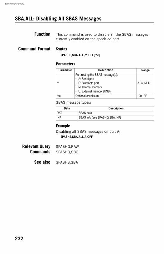
Set Command Library
SBA,ALL: Disabling All SBAS Messages
Function This command is used to disable all the SBAS messages currently enabled on the specified port.
Command Format Syntax$PASHS,SBA,ALL,c1,OFF[*cc]
Parameters
SBAS message types:
ExampleDisabling all SBAS messages on port A:
$PASHS,SBA,ALL,A,OFF
Relevant QueryCommands
$PASHQ,RAW$PASHQ,SBO
See also $PASHS,SBA
Parameter Description Range
c1
Port routing the SBAS message(s):• A: Serial port• C: Bluetooth port• M: Internal memory• U: External memory (USB)
A, C, M, U
*cc Optional checksum *00-*FF
Data DescriptionDAT SBAS dataINF SBAS info (see $PASHQ,SBA,INF)
232
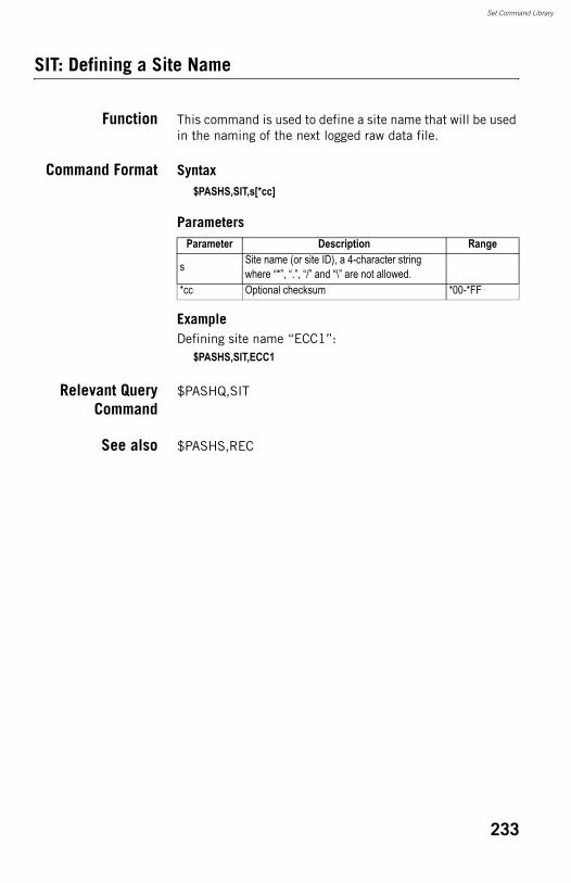
Set Command Library
SIT: Defining a Site Name
Function This command is used to define a site name that will be used in the naming of the next logged raw data file.
Command Format Syntax$PASHS,SIT,s[*cc]
Parameters
ExampleDefining site name “ECC1”:
$PASHS,SIT,ECC1
Relevant QueryCommand
$PASHQ,SIT
See also $PASHS,REC
Parameter Description Range
s Site name (or site ID), a 4-character string where “*”, “.”, “/” and “\” are not allowed.
*cc Optional checksum *00-*FF
233
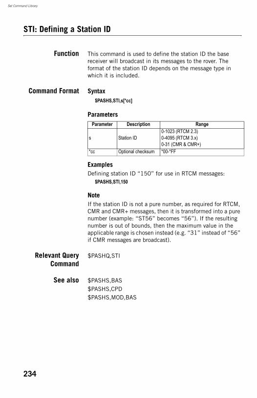
Set Command Library
STI: Defining a Station ID
Function This command is used to define the station ID the base receiver will broadcast in its messages to the rover. The format of the station ID depends on the message type in which it is included.
Command Format Syntax$PASHS,STI,s[*cc]
Parameters
ExamplesDefining station ID “150” for use in RTCM messages:
$PASHS,STI,150
NoteIf the station ID is not a pure number, as required for RTCM, CMR and CMR+ messages, then it is transformed into a pure number (example: “ST56” becomes “56”). If the resulting number is out of bounds, then the maximum value in the applicable range is chosen instead (e.g. “31” instead of “56” if CMR messages are broadcast).
Relevant QueryCommand
$PASHQ,STI
See also $PASHS,BAS$PASHS,CPD$PASHS,MOD,BAS
Parameter Description Range
s Station ID0-1023 (RTCM 2.3)0-4095 (RTCM 3.x)0-31 (CMR & CMR+)
*cc Optional checksum *00-*FF
234
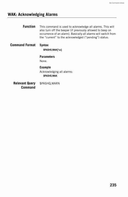
Set Command Library
WAK: Acknowledging Alarms
Function This command is used to acknowledge all alarms. This will also turn off the beeper (if previously allowed to beep on occurrence of an alarm). Basically all alarms will switch from the “current” to the acknowledged (“pending”) status.
Command Format Syntax$PASHS,WAK[*cc]
ParametersNone.
ExampleAcknowledging all alarms:
$PASHS,WAK
Relevant QueryCommand
$PASHQ,WARN
235
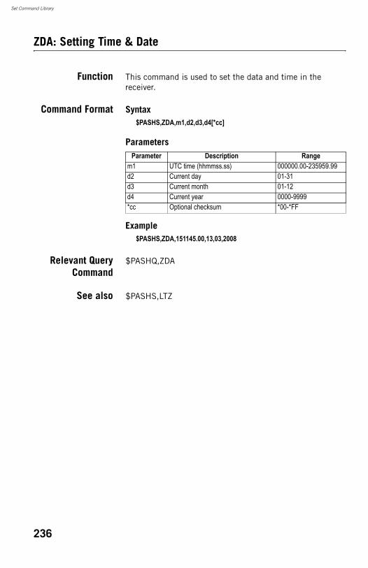
Set Command Library
ZDA: Setting Time & Date
Function This command is used to set the data and time in the receiver.
Command Format Syntax$PASHS,ZDA,m1,d2,d3,d4[*cc]
Parameters
Example$PASHS,ZDA,151145.00,13,03,2008
Relevant QueryCommand
$PASHQ,ZDA
See also $PASHS,LTZ
Parameter Description Rangem1 UTC time (hhmmss.ss) 000000.00-235959.99d2 Current day 01-31d3 Current month 01-12d4 Current year 0000-9999*cc Optional checksum *00-*FF
236
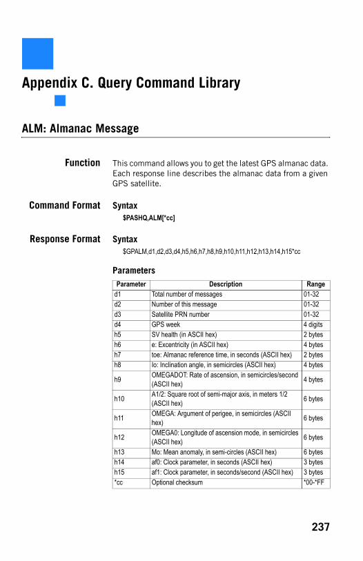
Appendix C. Query Command Library
ALM: Almanac Message
Function This command allows you to get the latest GPS almanac data. Each response line describes the almanac data from a given GPS satellite.
Command Format Syntax$PASHQ,ALM[*cc]
Response Format Syntax$GPALM,d1,d2,d3,d4,h5,h6,h7,h8,h9,h10,h11,h12,h13,h14,h15*cc
ParametersParameter Description Range
d1 Total number of messages 01-32d2 Number of this message 01-32d3 Satellite PRN number 01-32d4 GPS week 4 digitsh5 SV health (in ASCII hex) 2 bytesh6 e: Excentricity (in ASCII hex) 4 bytesh7 toe: Almanac reference time, in seconds (ASCII hex) 2 bytesh8 Io: Inclination angle, in semicircles (ASCII hex) 4 bytes
h9 OMEGADOT: Rate of ascension, in semicircles/second (ASCII hex) 4 bytes
h10 A1/2: Square root of semi-major axis, in meters 1/2 (ASCII hex) 6 bytes
h11 OMEGA: Argument of perigee, in semicircles (ASCII hex) 6 bytes
h12 OMEGA0: Longitude of ascension mode, in semicircles (ASCII hex) 6 bytes
h13 Mo: Mean anomaly, in semi-circles (ASCII hex) 6 bytesh14 af0: Clock parameter, in seconds (ASCII hex) 3 bytesh15 af1: Clock parameter, in seconds/second (ASCII hex) 3 bytes*cc Optional checksum *00-*FF
237

Query Command Library
Example $PASHQ,ALM$GPALM,31,1,01,65535,00,39A8,4E,1FEA,FD65,A10C8C,B777FE,935A86,C994BE,0C6,001*73$GPALM,31,2,02,65535,00,4830,4E,00D9,FD49,A10D24,64A66D,3B6857,E6F2A3,0BA,001*7A$GPALM,31,3,03,65535,00,552B,4E,F572,FD3B,A10CE1,20E624,0CD7E1,D10C32,0CA,001*0D$GPALM,31,4,04,65535,00,4298,4E,0069,FD46,A10D5C,0EE3DC,3C2E3E,51DDF9,FF0,FFF*0A...
238
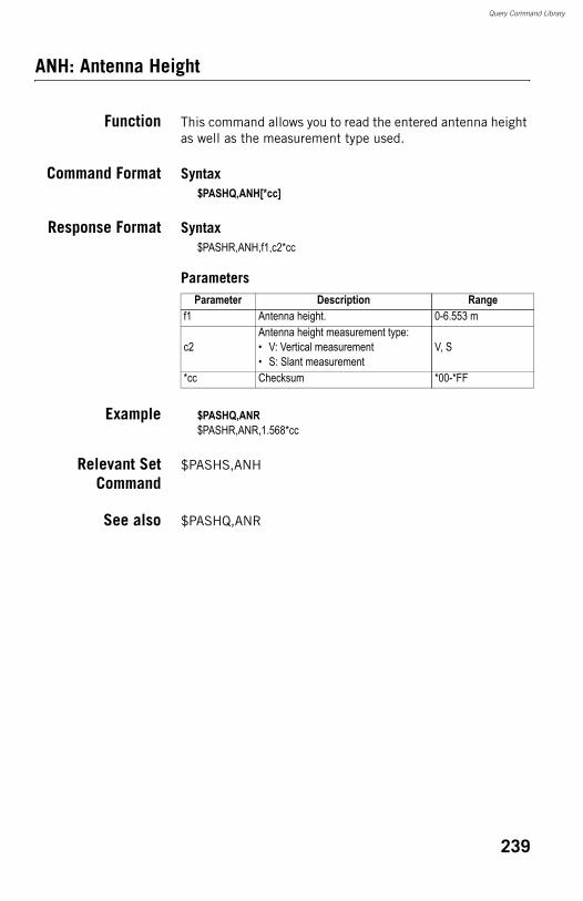
Query Command Library
ANH: Antenna Height
Function This command allows you to read the entered antenna height as well as the measurement type used.
Command Format Syntax$PASHQ,ANH[*cc]
Response Format Syntax$PASHR,ANH,f1,c2*cc
Parameters
Example $PASHQ,ANR$PASHR,ANR,1.568*cc
Relevant SetCommand
$PASHS,ANH
See also $PASHQ,ANR
Parameter Description Rangef1 Antenna height. 0-6.553 m
c2Antenna height measurement type:• V: Vertical measurement• S: Slant measurement
V, S
*cc Checksum *00-*FF
239
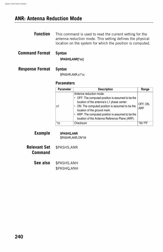
Query Command Library
ANR: Antenna Reduction Mode
Function This command is used to read the current setting for the antenna reduction mode. This setting defines the physical location on the system for which the position is computed.
Command Format Syntax$PASHQ,ANR[*cc]
Response Format Syntax$PASHR,ANR,s1*cc
Parameters
Example $PASHQ,ANR$PASHR,ANR,ON*04
Relevant SetCommand
$PASHS,ANR
See also $PASHS,ANH$PASHQ,ANH
Parameter Description Range
s1
Antenna reduction mode:• OFF: The computed position is assumed to be the
location of the antenna’s L1 phase center.• ON: The computed position is assumed to be the
location of the ground mark.• ARP: The computed position is assumed to be the
location of the Antenna Reference Plane (ARP).
OFF, ON, ARP
*cc Checksum *00-*FF
240
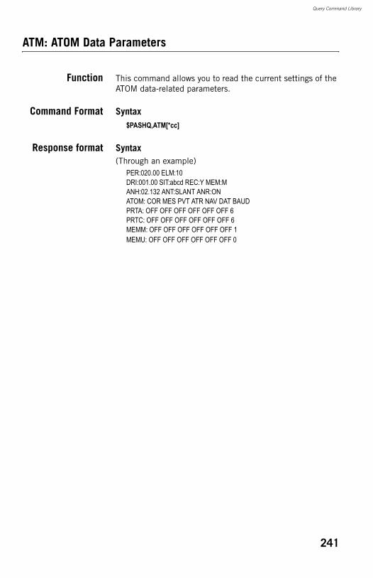
Query Command Library
ATM: ATOM Data Parameters
Function This command allows you to read the current settings of the ATOM data-related parameters.
Command Format Syntax$PASHQ,ATM[*cc]
Response format Syntax(Through an example)
PER:020.00 ELM:10DRI:001.00 SIT:abcd REC:Y MEM:MANH:02.132 ANT:SLANT ANR:ONATOM: COR MES PVT ATR NAV DAT BAUDPRTA: OFF OFF OFF OFF OFF OFF 6PRTC: OFF OFF OFF OFF OFF OFF 6MEMM: OFF OFF OFF OFF OFF OFF 1MEMU: OFF OFF OFF OFF OFF OFF 0
241
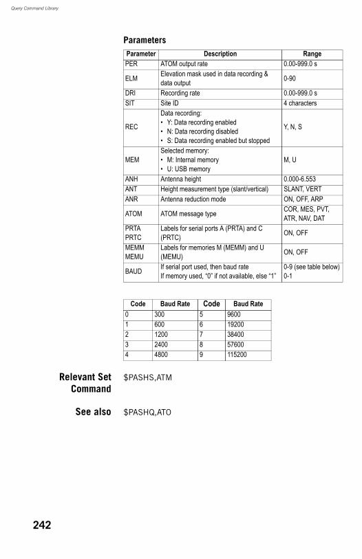
Query Command Library
Parameters
Relevant SetCommand
$PASHS,ATM
See also $PASHQ,ATO
Parameter Description RangePER ATOM output rate 0.00-999.0 s
ELM Elevation mask used in data recording & data output 0-90
DRI Recording rate 0.00-999.0 sSIT Site ID 4 characters
REC
Data recording:• Y: Data recording enabled• N: Data recording disabled• S: Data recording enabled but stopped
Y, N, S
MEMSelected memory:• M: Internal memory• U: USB memory
M, U
ANH Antenna height 0.000-6.553ANT Height measurement type (slant/vertical) SLANT, VERTANR Antenna reduction mode ON, OFF, ARP
ATOM ATOM message type COR, MES, PVT, ATR, NAV, DAT
PRTAPRTC
Labels for serial ports A (PRTA) and C (PRTC) ON, OFF
MEMMMEMU
Labels for memories M (MEMM) and U (MEMU) ON, OFF
BAUD If serial port used, then baud rateIf memory used, “0” if not available, else “1”
0-9 (see table below)0-1
Code Baud Rate Code Baud Rate0 300 5 96001 600 6 192002 1200 7 384003 2400 8 576004 4800 9 115200
242
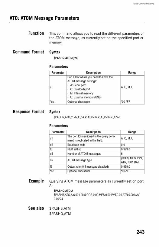
Query Command Library
ATO: ATOM Message Parameters
Function This command allows you to read the different parameters of the ATOM message, as currently set on the specified port or memory.
Command Format Syntax$PASHQ,ATO,c[*cc]
Parameters
Response Format Syntax$PASHR,ATO,c1,d2,f3,d4,s5,f6,s5,f6,s5,f6,s5,f6,s5,f6*cc
Parameters
Example Querying ATOM message parameters as currently set on port A:
$PASHQ,ATO,A$PASHR,ATO,A,6,001.00,5,COR,0.00,MES,0.00,PVT,0.00,ATR,0.00,NAV,0.00*24
See also $PASHS,ATM$PASHQ,ATM
Parameter Description Range
c
Port ID for which you need to know the ATOM message settings:• A: Serial port• C: Bluetooth port• M: Internal memory• U: External memory (USB)
A, C, M, U
*cc Optional checksum *00-*FF
Parameter Description Range
c1 The port ID mentioned in the query com-mand is replicated in this field. A, C, M, U
d2 Baud rate code 0-9f3 PER setting 0-999.0d4 Number of ATOM messages 6
s5 ATOM message type (COR), MES, PVT, ATR, NAV, DAT
f6 Output rate (0 if messgae disabled) 0-999.0*cc Optional checksum *00-*FF
243
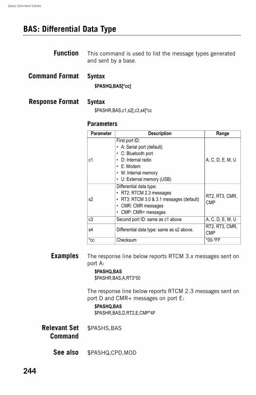
Query Command Library
BAS: Differential Data Type
Function This command is used to list the message types generated and sent by a base.
Command Format Syntax$PASHQ,BAS[*cc]
Response Format Syntax$PASHR,BAS,c1,s2[,c3,s4]*cc
Parameters
Examples The response line below reports RTCM 3.x messages sent on port A:
$PASHQ,BAS$PASHR,BAS,A,RT3*50
The response line below reports RTCM 2.3 messages sent on port D and CMR+ messages on port E:
$PASHQ,BAS$PASHR,BAS,D,RT2,E,CMP*4F
Relevant SetCommand
$PASHS,BAS
See also $PASHQ,CPD,MOD
Parameter Description Range
c1
First port ID:• A: Serial port (default)• C: Bluetooth port• D: Internal radio• E: Modem• M: Internal memory• U: External memory (USB)
A, C, D, E, M, U
s2
Differential data type:• RT2: RTCM 2.3 messages• RT3: RTCM 3.0 & 3.1 messages (default)• CMR: CMR messages• CMP: CMR+ messages
RT2, RT3, CMR, CMP
c3 Second port ID: same as c1 above A, C, D, E, M, U
s4 Differential data type: same as s2 above. RT2, RT3, CMR, CMP
*cc Checksum *00-*FF
244
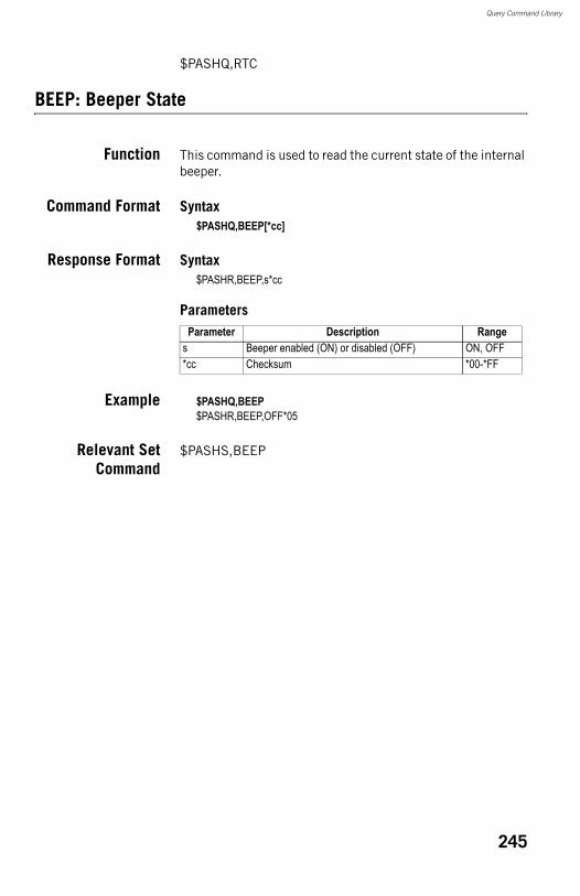
Query Command Library
$PASHQ,RTC
BEEP: Beeper State
Function This command is used to read the current state of the internal beeper.
Command Format Syntax$PASHQ,BEEP[*cc]
Response Format Syntax$PASHR,BEEP,s*cc
Parameters
Example $PASHQ,BEEP$PASHR,BEEP,OFF*05
Relevant SetCommand
$PASHS,BEEP
Parameter Description Ranges Beeper enabled (ON) or disabled (OFF) ON, OFF*cc Checksum *00-*FF
245
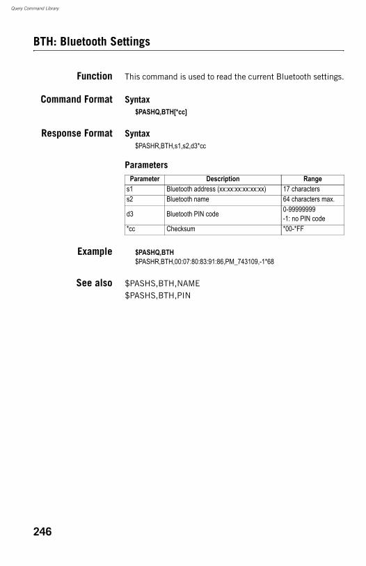
Query Command Library
BTH: Bluetooth Settings
Function This command is used to read the current Bluetooth settings.
Command Format Syntax$PASHQ,BTH[*cc]
Response Format Syntax$PASHR,BTH,s1,s2,d3*cc
Parameters
Example $PASHQ,BTH$PASHR,BTH,00:07:80:83:91:86,PM_743109,-1*68
See also $PASHS,BTH,NAME$PASHS,BTH,PIN
Parameter Description Ranges1 Bluetooth address (xx:xx:xx:xx:xx:xx) 17 characterss2 Bluetooth name 64 characters max.
d3 Bluetooth PIN code 0-99999999-1: no PIN code
*cc Checksum *00-*FF
246
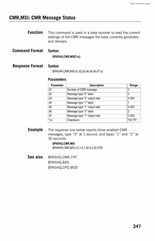
Query Command Library
CMR,MSI: CMR Message Status
Function This command is used in a base receiver to read the current settings of the CMR messages the base currently generates and delivers.
Command Format Syntax$PASHQ,CMR,MSI[*cc]
Response Format Syntax$PASHR,CMR,MSI,d1,d2,d3,d4,d5,d6,d7*cc
Parameters
Example The response line below reports three enabled CMR messages, type “0” at 1 second, and types “1” and “2” at 30 seconds:
$PASHQ,CMR,MSI$PASHR,CMR,MSI,3,0,1.0,1,30.0,2,30.0*50
See also $PASHS,CMR,TYP$PASHQ,BAS$PASHQ,CPD,MOD
Parameter Description Ranged1 Number of CMR message 3d2 Message type “0” label 0d3 Message type “0” output rate 0-300d4 Message type “1” label 1d5 Message type “1” output rate 0-300d6 Message type “2” label 2d7 Message type “1” output rate 0-300*cc Checksum *00-*FF
247
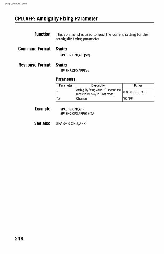
Query Command Library
CPD,AFP: Ambiguity Fixing Parameter
Function This command is used to read the current setting for the ambiguity fixing parameter.
Command Format Syntax$PASHQ,CPD,AFP[*cc]
Response Format Syntax$PASHR,CPD,AFP,f*cc
Parameters
Example $PASHQ,CPD,AFP$PASHQ,CPD,AFP,99.0*5A
See also $PASHS,CPD,AFP
Parameter Description Range
f Ambiguity fixing value. “0” means the receiver will stay in Float mode. 0, 95.0, 99.0, 99.9
*cc Checksum *00-*FF
248
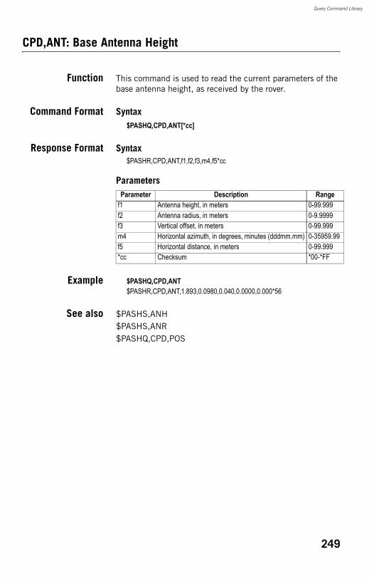
Query Command Library
CPD,ANT: Base Antenna Height
Function This command is used to read the current parameters of the base antenna height, as received by the rover.
Command Format Syntax$PASHQ,CPD,ANT[*cc]
Response Format Syntax$PASHR,CPD,ANT,f1,f2,f3,m4,f5*cc
Parameters
Example $PASHQ,CPD,ANT$PASHR,CPD,ANT,1.893,0.0980,0.040,0.0000,0.000*56
See also $PASHS,ANH$PASHS,ANR$PASHQ,CPD,POS
Parameter Description Rangef1 Antenna height, in meters 0-99.999f2 Antenna radius, in meters 0-9.9999f3 Vertical offset, in meters 0-99.999m4 Horizontal azimuth, in degrees, minutes (dddmm.mm) 0-35959.99f5 Horizontal distance, in meters 0-99.999*cc Checksum *00-*FF
249
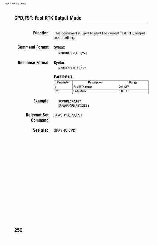
Query Command Library
CPD,FST: Fast RTK Output Mode
Function This command is used to read the current fast RTK output mode setting.
Command Format Syntax$PASHQ,CPD,FST[*cc]
Response Format Syntax$PASHR,CPD,FST,s*cc
Parameters
Example $PASHQ,CPD,FST$PASHR,CPD,FST,ON*63
Relevant SetCommand
$PASHS,CPD,FST
See also $PASHQ,CPD
Parameter Description Ranges Fast RTK mode ON, OFF*cc Checksum *00-*FF
250
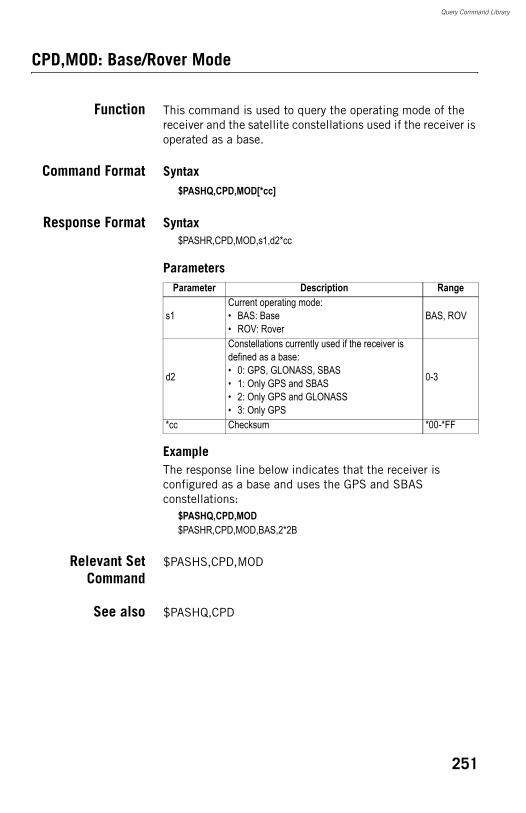
Query Command Library
CPD,MOD: Base/Rover Mode
Function This command is used to query the operating mode of the receiver and the satellite constellations used if the receiver is operated as a base.
Command Format Syntax$PASHQ,CPD,MOD[*cc]
Response Format Syntax$PASHR,CPD,MOD,s1,d2*cc
Parameters
ExampleThe response line below indicates that the receiver is configured as a base and uses the GPS and SBAS constellations:
$PASHQ,CPD,MOD$PASHR,CPD,MOD,BAS,2*2B
Relevant SetCommand
$PASHS,CPD,MOD
See also $PASHQ,CPD
Parameter Description Range
s1Current operating mode:• BAS: Base• ROV: Rover
BAS, ROV
d2
Constellations currently used if the receiver is defined as a base:• 0: GPS, GLONASS, SBAS• 1: Only GPS and SBAS• 2: Only GPS and GLONASS• 3: Only GPS
0-3
*cc Checksum *00-*FF
251
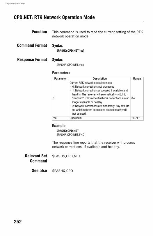
Query Command Library
CPD,NET: RTK Network Operation Mode
Function This command is used to read the current setting of the RTK network operation mode.
Command Format Syntax$PASHQ,CPD,NET[*cc]
Response Format Syntax$PASHR,CPD,NET,d*cc
Parameters
Example$PASHQ,CPD,NET$PASHR,CPD,NET,1*4D
The response line reports that the receiver will process network corrections, if available and healthy.
Relevant SetCommand
$PASHS,CPD,NET
See also $PASHQ,CPD
Parameter Description Range
d
Current RTK network operation mode:• 0: Network corrections not processed• 1: Network corrections processed if available and
healthy. The receiver will automatically switch to “standard” RTK mode if network corrections are no longer available or healthy.
• 2: Network corrections are mandatory. Any satellite for which network corrections are not healthy will not be used.
0-2
*cc Checksum *00-*FF
252
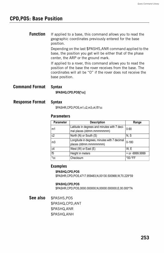
Query Command Library
CPD,POS: Base Position
Function If applied to a base, this command allows you to read the geographic coordinates previously entered for the base position.Depending on the last $PASHS,ANR command applied to the base, the position you get will be either that of the phase center, the ARP or the ground mark.If applied to a rover, this command allows you to read the position of the base the rover receives from the base. The coordinates will all be “0” if the rover does not receive the base position.
Command Format Syntax$PASHQ,CPD,POS[*cc]
Response Format Syntax$PASHR,CPD,POS,m1,c2,m3,c4,f5*cc
Parameters
Examples$PASHQ,CPD,POS$PASHR,CPD,POS,4717.959483,N,00130.500968,W,70.229*59
$PASHQ,CPD,POS$PASHR,CPD,POS,0000.000000,N,00000.000000,E,00.000*7A
See also $PASHS,POS$PASHQ,CPD,ANT$PASHQ,ANR$PASHQ,ANH
Parameter Description Range
m1 Latitude in degrees and minutes with 7 deci-mal places (ddmm.mmmmmmm) 0-90
c2 North (N) or South (S) N, S
m3 Longitude in degrees, minutes with 7 decimal places (ddmm.mmmmmmm) 0-180
c4 West (W) or East (E) W, Ef5 Height in meters + or -9999.9999*cc Checksum *00-*FF
253
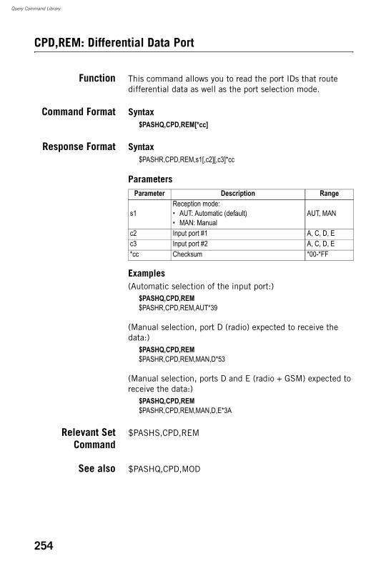
Query Command Library
CPD,REM: Differential Data Port
Function This command allows you to read the port IDs that route differential data as well as the port selection mode.
Command Format Syntax$PASHQ,CPD,REM[*cc]
Response Format Syntax$PASHR,CPD,REM,s1[,c2][,c3]*cc
Parameters
Examples(Automatic selection of the input port:)
$PASHQ,CPD,REM$PASHR,CPD,REM,AUT*39
(Manual selection, port D (radio) expected to receive the data:)
$PASHQ,CPD,REM$PASHR,CPD,REM,MAN,D*53
(Manual selection, ports D and E (radio + GSM) expected to receive the data:)
$PASHQ,CPD,REM$PASHR,CPD,REM,MAN,D,E*3A
Relevant SetCommand
$PASHS,CPD,REM
See also $PASHQ,CPD,MOD
Parameter Description Range
s1Reception mode:• AUT: Automatic (default)• MAN: Manual
AUT, MAN
c2 Input port #1 A, C, D, Ec3 Input port #2 A, C, D, E*cc Checksum *00-*FF
254
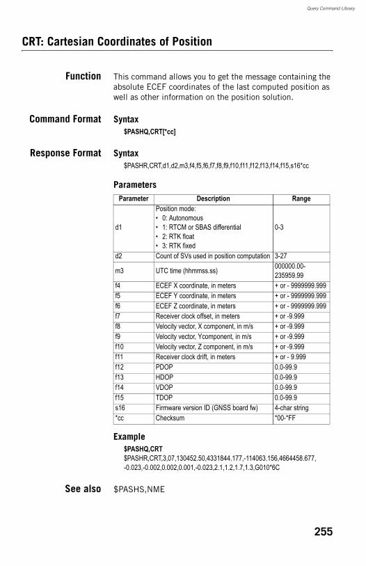
Query Command Library
CRT: Cartesian Coordinates of Position
Function This command allows you to get the message containing the absolute ECEF coordinates of the last computed position as well as other information on the position solution.
Command Format Syntax$PASHQ,CRT[*cc]
Response Format Syntax$PASHR,CRT,d1,d2,m3,f4,f5,f6,f7,f8,f9,f10,f11,f12,f13,f14,f15,s16*cc
Parameters
Example$PASHQ,CRT$PASHR,CRT,3,07,130452.50,4331844.177,-114063.156,4664458.677,-0.023,-0.002,0.002,0.001,-0.023,2.1,1.2,1.7,1.3,G010*6C
See also $PASHS,NME
Parameter Description Range
d1
Position mode:• 0: Autonomous• 1: RTCM or SBAS differential• 2: RTK float• 3: RTK fixed
0-3
d2 Count of SVs used in position computation 3-27
m3 UTC time (hhmmss.ss) 000000.00-235959.99
f4 ECEF X coordinate, in meters + or - 9999999.999f5 ECEF Y coordinate, in meters + or - 9999999.999f6 ECEF Z coordinate, in meters + or - 9999999.999f7 Receiver clock offset, in meters + or -9.999f8 Velocity vector, X component, in m/s + or -9.999f9 Velocity vector, Ycomponent, in m/s + or -9.999f10 Velocity vector, Z component, in m/s + or -9.999f11 Receiver clock drift, in meters + or - 9.999f12 PDOP 0.0-99.9f13 HDOP 0.0-99.9f14 VDOP 0.0-99.9f15 TDOP 0.0-99.9s16 Firmware version ID (GNSS board fw) 4-char string*cc Checksum *00-*FF
255
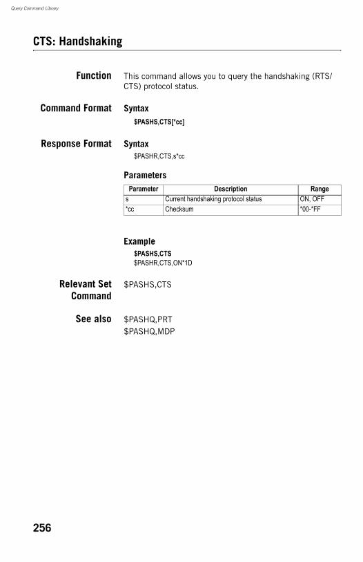
Query Command Library
CTS: Handshaking
Function This command allows you to query the handshaking (RTS/CTS) protocol status.
Command Format Syntax$PASHS,CTS[*cc]
Response Format Syntax$PASHR,CTS,s*cc
Parameters
Example$PASHS,CTS$PASHR,CTS,ON*1D
Relevant SetCommand
$PASHS,CTS
See also $PASHQ,PRT$PASHQ,MDP
Parameter Description Ranges Current handshaking protocol status ON, OFF*cc Checksum *00-*FF
256
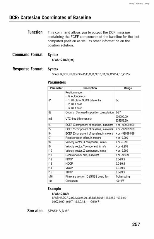
Query Command Library
DCR: Cartesian Coordinates of Baseline
Function This command allows you to output the DCR message containing the ECEF components of the baseline for the last computed position as well as other information on the position solution.
Command Format Syntax$PASHQ,DCR[*cc]
Response Format Syntax$PASHR,DCR,d1,d2,m3,f4,f5,f6,f7,f8,f9,f10,f11,f12,f13,f14,f15,s16*cc
Parameters
Example$PASHQ,DCR$PASHR,DCR,3,09,130924.00,-37.683,55.081,17.925,0.109,0.001,0.002,0.001,0.047,1.9,1.0,1.6,1.1,G010*71
See also $PASHS,NME
Parameter Description Range
d1
Position mode:• 0: Autonomous• 1: RTCM or SBAS differential• 2: RTK float• 3: RTK fixed
0-3
d2 Count of SVs used in position computation 3-27
m3 UTC time (hhmmss.ss) 000000.00-235959.99
f4 ECEF X component of baseline, in meters + or - 99999.999f5 ECEF Y component of baseline, in meters + or - 99999.999f6 ECEF Z component of baseline, in meters + or - 99999.999f7 Receiver clock offset, in meters + or -9.999f8 Velocity vector, X component, in m/s + or -9.999f9 Velocity vector, Ycomponent, in m/s + or -9.999f10 Velocity vector, Z component, in m/s + or -9.999f11 Receiver clock drift, in meters + or - 9.999f12 PDOP 0.0-99.9f13 HDOP 0.0-99.9f14 VDOP 0.0-99.9f15 TDOP 0.0-99.9s16 Firmware version ID (GNSS board fw) 4-char string*cc Checksum *00-*FF
257
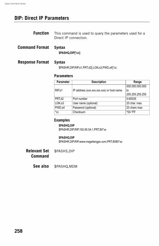
Query Command Library
DIP: Direct IP Parameters
Function This command is used to query the parameters used for a Direct IP connection.
Command Format Syntax$PASHQ,DIP[*cc]
Response Format Syntax$PASHR,DIP,RIP,s1,PRT,d2[,LGN,s3,PWD,s4]*cc
Parameters
Examples$PASHQ,DIP$PASHR,DIP,RIP,192.65.54.1,PRT,80*xx
$PASHQ,DIP$PASHR,DIP,RIP,www.magellangps.com,PRT,8080*xx
Relevant SetCommand
$PASHS,DIP
See also $PASHQ,MDM
Parameter Description Range
RIP,s1 IP address (xxx.xxx.xxx.xxx) or host name000.000.000.000 to 255.255.255.255
PRT,d2 Port number 0-65535LGN,s3 User name (optional) 20 char. max.PWD,s4 Password (optional) 20 chars max.*cc Checksum *00-*FF
258
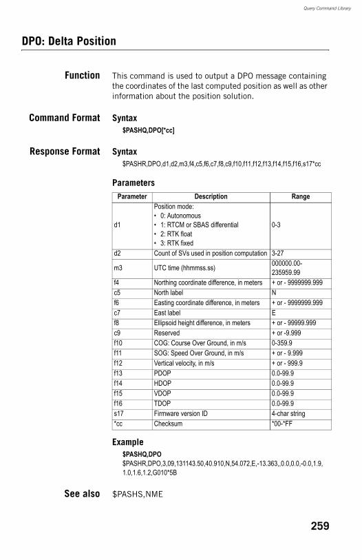
Query Command Library
DPO: Delta Position
Function This command is used to output a DPO message containing the coordinates of the last computed position as well as other information about the position solution.
Command Format Syntax$PASHQ,DPO[*cc]
Response Format Syntax$PASHR,DPO,d1,d2,m3,f4,c5,f6,c7,f8,c9,f10,f11,f12,f13,f14,f15,f16,s17*cc
Parameters
Example$PASHQ,DPO$PASHR,DPO,3,09,131143.50,40.910,N,54.072,E,-13.363,,0.0,0.0,-0.0,1.9,1.0,1.6,1.2,G010*5B
See also $PASHS,NME
Parameter Description Range
d1
Position mode:• 0: Autonomous• 1: RTCM or SBAS differential• 2: RTK float• 3: RTK fixed
0-3
d2 Count of SVs used in position computation 3-27
m3 UTC time (hhmmss.ss) 000000.00-235959.99
f4 Northing coordinate difference, in meters + or - 9999999.999c5 North label Nf6 Easting coordinate difference, in meters + or - 9999999.999c7 East label Ef8 Ellipsoid height difference, in meters + or - 99999.999c9 Reserved + or -9.999f10 COG: Course Over Ground, in m/s 0-359.9f11 SOG: Speed Over Ground, in m/s + or - 9.999f12 Vertical velocity, in m/s + or - 999.9f13 PDOP 0.0-99.9f14 HDOP 0.0-99.9f15 VDOP 0.0-99.9f16 TDOP 0.0-99.9s17 Firmware version ID 4-char string*cc Checksum *00-*FF
259
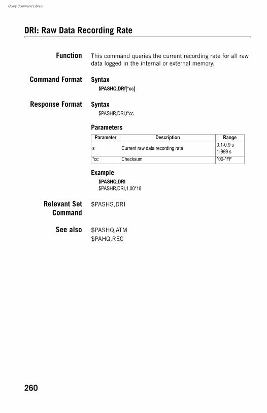
Query Command Library
DRI: Raw Data Recording Rate
Function This command queries the current recording rate for all raw data logged in the internal or external memory.
Command Format Syntax$PASHQ,DRf[*cc]
Response Format Syntax$PASHR,DRI,f*cc
Parameters
Example$PASHQ,DRI$PASHR,DRI,1.00*18
Relevant SetCommand
$PASHS,DRI
See also $PASHQ,ATM$PAHQ,REC
Parameter Description Range
s Current raw data recording rate 0.1-0.9 s1-999 s
*cc Checksum *00-*FF
260
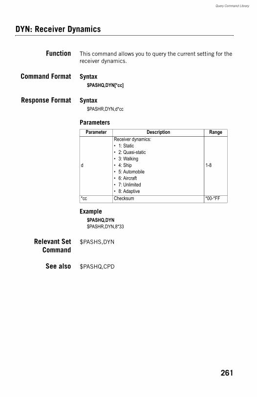
Query Command Library
DYN: Receiver Dynamics
Function This command allows you to query the current setting for the receiver dynamics.
Command Format Syntax$PASHQ,DYN[*cc]
Response Format Syntax$PASHR,DYN,d*cc
Parameters
Example$PASHQ,DYN$PASHR,DYN,8*33
Relevant SetCommand
$PASHS,DYN
See also $PASHQ,CPD
Parameter Description Range
d
Receiver dynamics:• 1: Static• 2: Quasi-static• 3: Walking• 4: Ship• 5: Automobile• 6: Aircraft• 7: Unlimited• 8: Adaptive
1-8
*cc Checksum *00-*FF
261
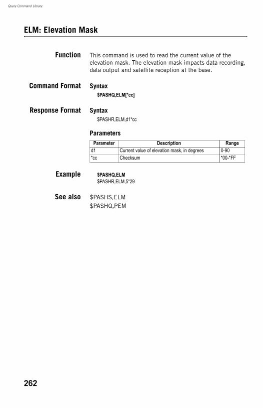
Query Command Library
ELM: Elevation Mask
Function This command is used to read the current value of the elevation mask. The elevation mask impacts data recording, data output and satellite reception at the base.
Command Format Syntax$PASHQ,ELM[*cc]
Response Format Syntax$PASHR,ELM,d1*cc
Parameters
Example $PASHQ,ELM$PASHR,ELM,5*29
See also $PASHS,ELM$PASHQ,PEM
Parameter Description Ranged1 Current value of elevation mask, in degrees 0-90*cc Checksum *00-*FF
262
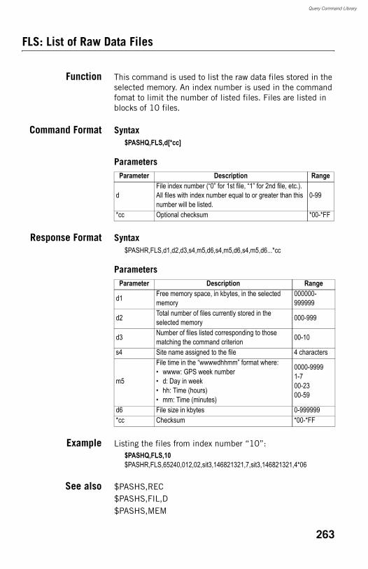
Query Command Library
FLS: List of Raw Data Files
Function This command is used to list the raw data files stored in the selected memory. An index number is used in the command fomat to limit the number of listed files. Files are listed in blocks of 10 files.
Command Format Syntax$PASHQ,FLS,d[*cc]
Parameters
Response Format Syntax$PASHR,FLS,d1,d2,d3,s4,m5,d6,s4,m5,d6,s4,m5,d6...*cc
Parameters
Example Listing the files from index number “10”:$PASHQ,FLS,10$PASHR,FLS,65240,012,02,sit3,146821321,7,sit3,146821321,4*06
See also $PASHS,REC$PASHS,FIL,D$PASHS,MEM
Parameter Description Range
dFile index number (“0” for 1st file, “1” for 2nd file, etc.). All files with index number equal to or greater than this number will be listed.
0-99
*cc Optional checksum *00-*FF
Parameter Description Range
d1 Free memory space, in kbytes, in the selected memory
000000-999999
d2 Total number of files currently stored in the selected memory 000-999
d3 Number of files listed corresponding to those matching the command criterion 00-10
s4 Site name assigned to the file 4 characters
m5
File time in the “wwwwdhhmm” format where:• wwww: GPS week number• d: Day in week• hh: Time (hours)• mm: Time (minutes)
0000-99991-700-2300-59
d6 File size in kbytes 0-999999*cc Checksum *00-*FF
263
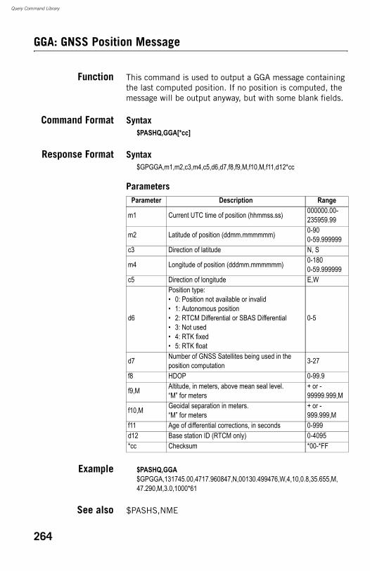
Query Command Library
GGA: GNSS Position Message
Function This command is used to output a GGA message containing the last computed position. If no position is computed, the message will be output anyway, but with some blank fields.
Command Format Syntax$PASHQ,GGA[*cc]
Response Format Syntax$GPGGA,m1,m2,c3,m4,c5,d6,d7,f8,f9,M,f10,M,f11,d12*cc
Parameters
Example $PASHQ,GGA$GPGGA,131745.00,4717.960847,N,00130.499476,W,4,10,0.8,35.655,M,47.290,M,3.0,1000*61
See also $PASHS,NME
Parameter Description Range
m1 Current UTC time of position (hhmmss.ss) 000000.00-235959.99
m2 Latitude of position (ddmm.mmmmmm) 0-900-59.999999
c3 Direction of latitude N, S
m4 Longitude of position (dddmm.mmmmmm) 0-1800-59.999999
c5 Direction of longitude E,W
d6
Position type:• 0: Position not available or invalid• 1: Autonomous position• 2: RTCM Differential or SBAS Differential• 3: Not used• 4: RTK fixed• 5: RTK float
0-5
d7 Number of GNSS Satellites being used in the position computation 3-27
f8 HDOP 0-99.9
f9,M Altitude, in meters, above mean seal level.“M” for meters
+ or - 99999.999,M
f10,M Geoidal separation in meters.“M” for meters
+ or - 999.999,M
f11 Age of differential corrections, in seconds 0-999d12 Base station ID (RTCM only) 0-4095*cc Checksum *00-*FF
264
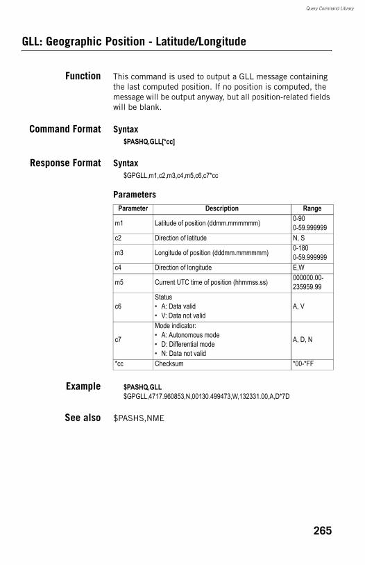
Query Command Library
GLL: Geographic Position - Latitude/Longitude
Function This command is used to output a GLL message containing the last computed position. If no position is computed, the message will be output anyway, but all position-related fields will be blank.
Command Format Syntax$PASHQ,GLL[*cc]
Response Format Syntax$GPGLL,m1,c2,m3,c4,m5,c6,c7*cc
Parameters
Example $PASHQ,GLL$GPGLL,4717.960853,N,00130.499473,W,132331.00,A,D*7D
See also $PASHS,NME
Parameter Description Range
m1 Latitude of position (ddmm.mmmmmm) 0-900-59.999999
c2 Direction of latitude N, S
m3 Longitude of position (dddmm.mmmmmm) 0-1800-59.999999
c4 Direction of longitude E,W
m5 Current UTC time of position (hhmmss.ss) 000000.00-235959.99
c6Status• A: Data valid• V: Data not valid
A, V
c7
Mode indicator:• A: Autonomous mode• D: Differential mode• N: Data not valid
A, D, N
*cc Checksum *00-*FF
265
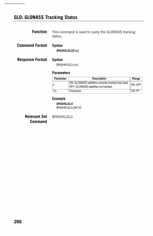
Query Command Library
GLO: GLONASS Tracking Status
Function This command is used to query the GLONASS tracking status.
Command Format Syntax$PASHQ,GLO[*cc]
Response Format Syntax$PASHR,GLO,s*cc
Parameters
Example$PASHQ,GLO$PASHR,GLO,ON*1D
Relevant SetCommand
$PASHS,GLO
Parameter Description Range
s ON: GLONASS satellites currently tracked and used.OFF: GLONASS satellites not tracked. ON, OFF
*cc Checksum *00-*FF
266
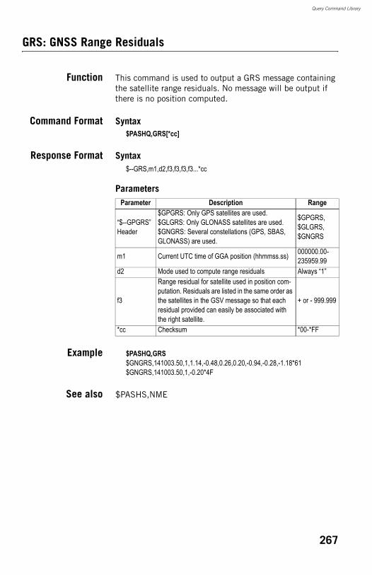
Query Command Library
GRS: GNSS Range Residuals
Function This command is used to output a GRS message containing the satellite range residuals. No message will be output if there is no position computed.
Command Format Syntax$PASHQ,GRS[*cc]
Response Format Syntax$--GRS,m1,d2,f3,f3,f3,f3...*cc
Parameters
Example $PASHQ,GRS$GNGRS,141003.50,1,1.14,-0.48,0.26,0.20,-0.94,-0.28,-1.18*61$GNGRS,141003.50,1,-0.20*4F
See also $PASHS,NME
Parameter Description Range
“$--GPGRS” Header
$GPGRS: Only GPS satellites are used.$GLGRS: Only GLONASS satellites are used.$GNGRS: Several constellations (GPS, SBAS, GLONASS) are used.
$GPGRS, $GLGRS, $GNGRS
m1 Current UTC time of GGA position (hhmmss.ss) 000000.00-235959.99
d2 Mode used to compute range residuals Always “1”
f3
Range residual for satellite used in position com-putation. Residuals are listed in the same order as the satellites in the GSV message so that each residual provided can easily be associated with the right satellite.
+ or - 999.999
*cc Checksum *00-*FF
267
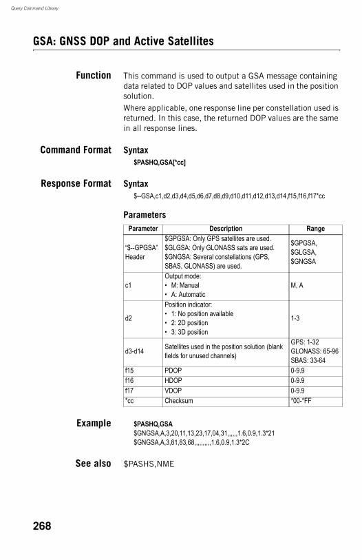
Query Command Library
GSA: GNSS DOP and Active Satellites
Function This command is used to output a GSA message containing data related to DOP values and satellites used in the position solution.Where applicable, one response line per constellation used is returned. In this case, the returned DOP values are the same in all response lines.
Command Format Syntax$PASHQ,GSA[*cc]
Response Format Syntax$--GSA,c1,d2,d3,d4,d5,d6,d7,d8,d9,d10,d11,d12,d13,d14,f15,f16,f17*cc
Parameters
Example $PASHQ,GSA$GNGSA,A,3,20,11,13,23,17,04,31,,,,,,1.6,0.9,1.3*21$GNGSA,A,3,81,83,68,,,,,,,,,,1.6,0.9,1.3*2C
See also $PASHS,NME
Parameter Description Range
“$--GPGSA” Header
$GPGSA: Only GPS satellites are used.$GLGSA: Only GLONASS sats are used.$GNGSA: Several constellations (GPS, SBAS, GLONASS) are used.
$GPGSA, $GLGSA, $GNGSA
c1Output mode:• M: Manual• A: Automatic
M, A
d2
Position indicator:• 1: No position available• 2: 2D position• 3: 3D position
1-3
d3-d14 Satellites used in the position solution (blank fields for unused channels)
GPS: 1-32GLONASS: 65-96SBAS: 33-64
f15 PDOP 0-9.9f16 HDOP 0-9.9f17 VDOP 0-9.9*cc Checksum *00-*FF
268
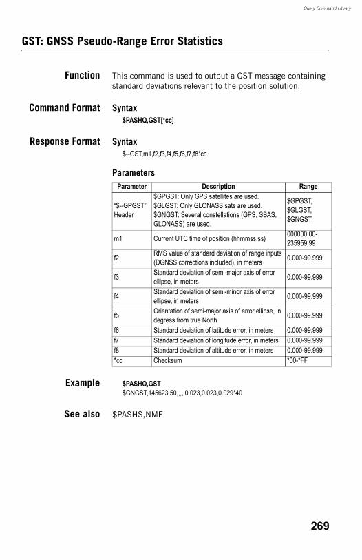
Query Command Library
GST: GNSS Pseudo-Range Error Statistics
Function This command is used to output a GST message containing standard deviations relevant to the position solution.
Command Format Syntax$PASHQ,GST[*cc]
Response Format Syntax$--GST,m1,f2,f3,f4,f5,f6,f7,f8*cc
Parameters
Example $PASHQ,GST$GNGST,145623.50,,,,,0.023,0.023,0.029*40
See also $PASHS,NME
Parameter Description Range
“$--GPGST” Header
$GPGST: Only GPS satellites are used.$GLGST: Only GLONASS sats are used.$GNGST: Several constellations (GPS, SBAS, GLONASS) are used.
$GPGST, $GLGST, $GNGST
m1 Current UTC time of position (hhmmss.ss) 000000.00-235959.99
f2 RMS value of standard deviation of range inputs (DGNSS corrections included), in meters 0.000-99.999
f3 Standard deviation of semi-major axis of error ellipse, in meters 0.000-99.999
f4 Standard deviation of semi-minor axis of error ellipse, in meters 0.000-99.999
f5 Orientation of semi-major axis of error ellipse, in degress from true North 0.000-99.999
f6 Standard deviation of latitude error, in meters 0.000-99.999f7 Standard deviation of longitude error, in meters 0.000-99.999f8 Standard deviation of altitude error, in meters 0.000-99.999*cc Checksum *00-*FF
269
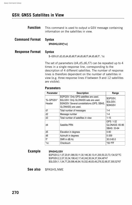
Query Command Library
GSV: GNSS Satellites in View
Function This command is used to output a GSV message containing information on the satellites in view.
Command Format Syntax$PASHQ,GSV[*cc]
Response Format Syntax$--GSV,d1,d2,d3,d4,d5,d6,f7,d4,d5,d6,f7,d4,d5,d6,f7...*cc
The set of parameters (d4,d5,d6,f7) can be repeated up to 4 times in a single response line, corresponding to the description of 4 different satellites. The number of response lines is therefore dependent on the number of satellites in view (e.g. three response lines if between 9 and 12 satellites are visible).
Parameters
Example $PASHQ,GSV$GPGSV,2,1,07,20,61,066,50,11,30,146,36,13,41,200,50,23,73,134,52*7C$GPGSV,2,2,07,33,34,198,42,17,40,242,50,04,37,304,48*47$GLGSV,1,1,04,77,29,098,46,84,19,332,46,83,49,276,52,68,57,300,52*67
See also $PASHS,NME
Parameter Description Range
“$--GPGSV” Header
$GPGSV: Only GPS satellites are used.$GLGSV: Only GLONASS sats are used.$GNGSV: Several constellations (GPS, SBAS, GLONASS) are used.
$GPGSV, $GLGSV, $GNGSV
d1 Total number of messages 1-4d2 Message number 1-4d3 Total number of satellites in view 1-15
d4 Satellite PRNGPS: 1-32GLONASS: 65-96SBAS: 33-64
d5 Elevation in degrees 0-90d6 Azimuth in degrees 0-359f7 SNR in dB.Hz 30.0-60.0*cc Checksum *00-*FF
270
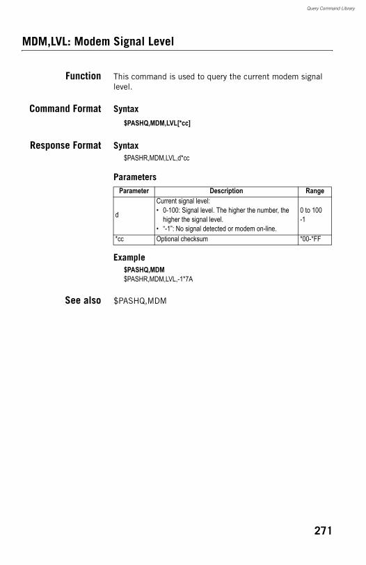
Query Command Library
MDM,LVL: Modem Signal Level
Function This command is used to query the current modem signal level.
Command Format Syntax$PASHQ,MDM,LVL[*cc]
Response Format Syntax$PASHR,MDM,LVL,d*cc
Parameters
Example$PASHQ,MDM$PASHR,MDM,LVL,-1*7A
See also $PASHQ,MDM
Parameter Description Range
d
Current signal level:• 0-100: Signal level. The higher the number, the
higher the signal level.• “-1”: No signal detected or modem on-line.
0 to 100-1
*cc Optional checksum *00-*FF
271

Query Command Library
MDM: Modem Status and Parameters
Function This command is used to query the modem status and parameters.
Command Format Syntax$PASHQ,MDM[*cc]
Response Format Syntax$PASHR,MDM,c1,d2,s3,PWR=s4,PIN=s5,BND=d6,PTC=d7,CBS=d8,APN=s9,LGN=s10,PWD=s11,IPT=d12,PHN=s13,ADL=c14,RNO=d15*cc
272
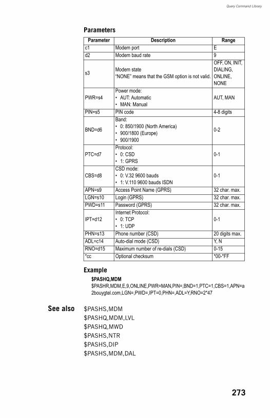
Query Command Library
Parameters
Example$PASHQ,MDM$PASHR,MDM,E,9,ONLINE,PWR=MAN,PIN=,BND=1,PTC=1,CBS=1,APN=a2bouygtel.com,LGN=,PWD=,IPT=0,PHN=,ADL=Y,RNO=2*47
See also $PASHS,MDM$PASHQ,MDM,LVL$PASHQ,MWD$PASHS,NTR$PASHS,DIP$PASHS,MDM,DAL
Parameter Description Rangec1 Modem port Ed2 Modem baud rate 9
s3 Modem state“NONE” means that the GSM option is not valid.
OFF, ON, INIT, DIALING, ONLINE, NONE
PWR=s4Power mode:• AUT: Automatic• MAN: Manual
AUT, MAN
PIN=s5 PIN code 4-8 digits
BND=d6
Band:• 0: 850/1900 (North America)• 900/1800 (Europe)• 900/1900
0-2
PTC=d7Protocol:• 0: CSD• 1: GPRS
0-1
CBS=d8CSD mode:• 0: V.32 9600 bauds• 1: V.110 9600 bauds ISDN
0-1
APN=s9 Access Point Name (GPRS) 32 char. max.LGN=s10 Login (GPRS) 32 char. max.PWD=s11 Password (GPRS) 32 char. max.
IPT=d12Internet Protocol:• 0: TCP• 1: UDP
0-1
PHN=s13 Phone number (CSD) 20 digits max.ADL=c14 Auto-dial mode (CSD) Y, NRNO=d15 Maximum number of re-dials (CSD) 0-15*cc Optional checksum *00-*FF
273
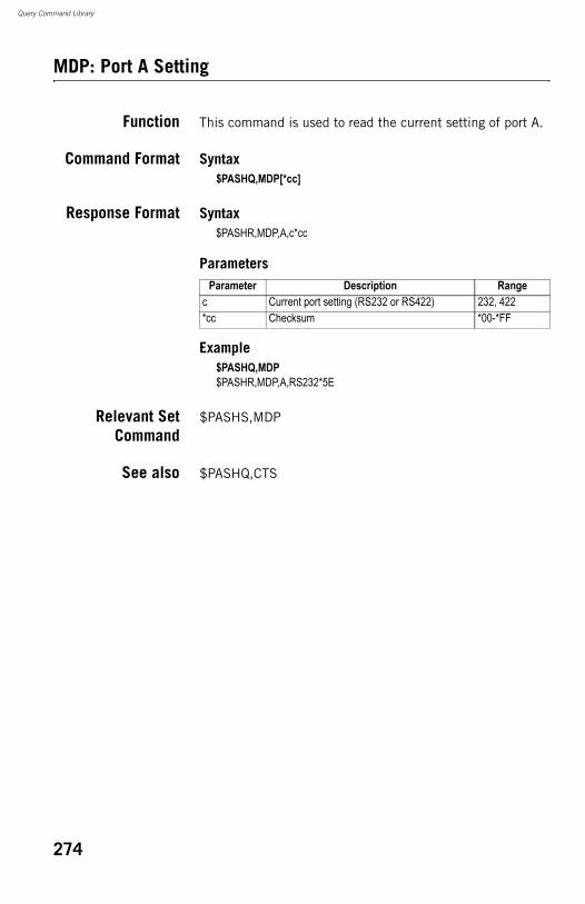
Query Command Library
MDP: Port A Setting
Function This command is used to read the current setting of port A.
Command Format Syntax$PASHQ,MDP[*cc]
Response Format Syntax$PASHR,MDP,A,c*cc
Parameters
Example$PASHQ,MDP$PASHR,MDP,A,RS232*5E
Relevant SetCommand
$PASHS,MDP
See also $PASHQ,CTS
Parameter Description Rangec Current port setting (RS232 or RS422) 232, 422*cc Checksum *00-*FF
274
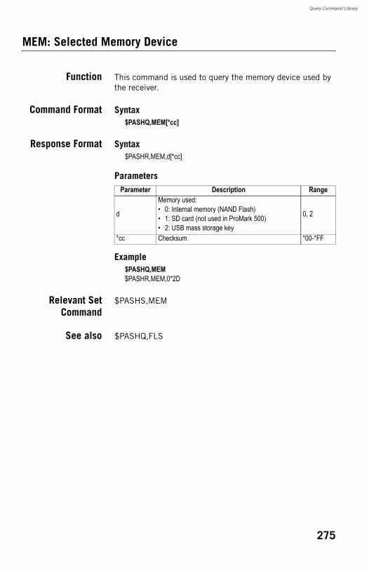
Query Command Library
MEM: Selected Memory Device
Function This command is used to query the memory device used by the receiver.
Command Format Syntax$PASHQ,MEM[*cc]
Response Format Syntax$PASHR,MEM,d[*cc]
Parameters
Example$PASHQ,MEM$PASHR,MEM,0*2D
Relevant SetCommand
$PASHS,MEM
See also $PASHQ,FLS
Parameter Description Range
d
Memory used:• 0: Internal memory (NAND Flash)• 1: SD card (not used in ProMark 500)• 2: USB mass storage key
0, 2
*cc Checksum *00-*FF
275
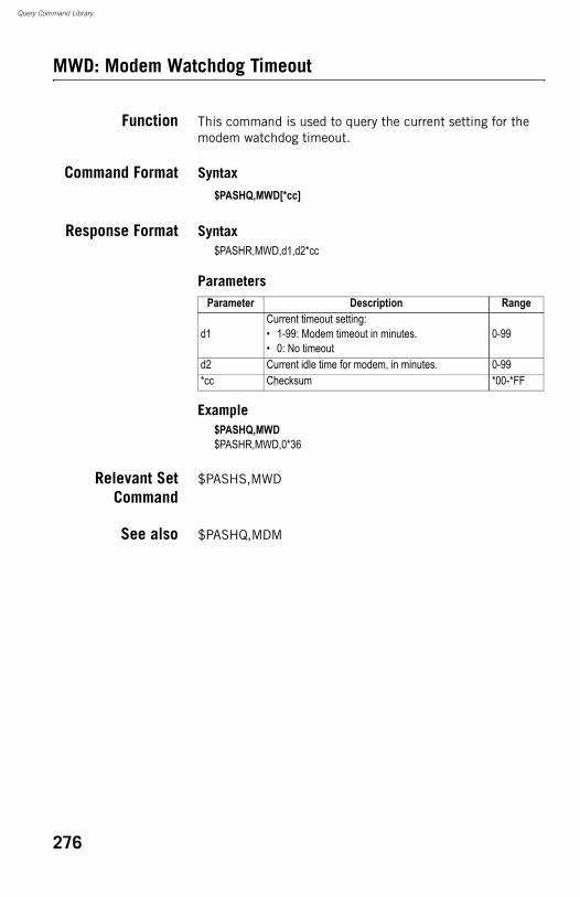
Query Command Library
MWD: Modem Watchdog Timeout
Function This command is used to query the current setting for the modem watchdog timeout.
Command Format Syntax$PASHQ,MWD[*cc]
Response Format Syntax$PASHR,MWD,d1,d2*cc
Parameters
Example$PASHQ,MWD$PASHR,MWD,0*36
Relevant SetCommand
$PASHS,MWD
See also $PASHQ,MDM
Parameter Description Range
d1Current timeout setting:• 1-99: Modem timeout in minutes.• 0: No timeout
0-99
d2 Current idle time for modem, in minutes. 0-99*cc Checksum *00-*FF
276
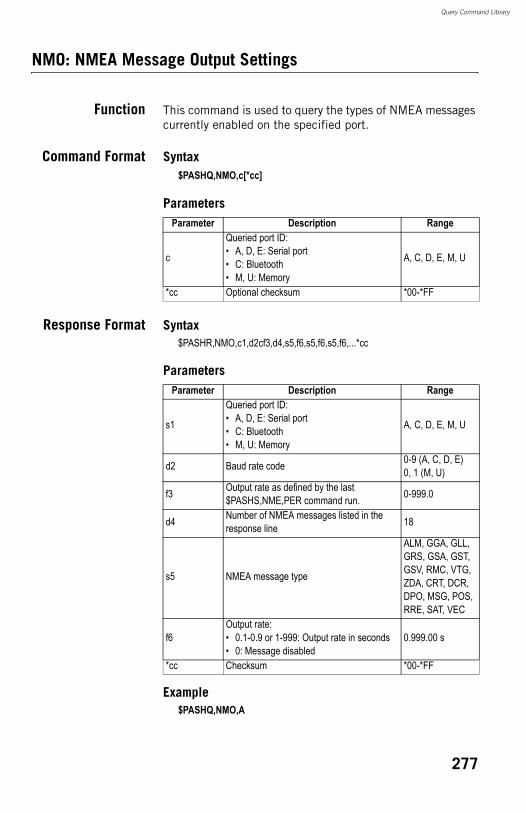
Query Command Library
NMO: NMEA Message Output Settings
Function This command is used to query the types of NMEA messages currently enabled on the specified port.
Command Format Syntax$PASHQ,NMO,c[*cc]
Parameters
Response Format Syntax$PASHR,NMO,c1,d2cf3,d4,s5,f6,s5,f6,s5,f6,...*cc
Parameters
Example$PASHQ,NMO,A
Parameter Description Range
c
Queried port ID:• A, D, E: Serial port• C: Bluetooth• M, U: Memory
A, C, D, E, M, U
*cc Optional checksum *00-*FF
Parameter Description Range
s1
Queried port ID:• A, D, E: Serial port• C: Bluetooth• M, U: Memory
A, C, D, E, M, U
d2 Baud rate code 0-9 (A, C, D, E)0, 1 (M, U)
f3 Output rate as defined by the last $PASHS,NME,PER command run. 0-999.0
d4 Number of NMEA messages listed in the response line 18
s5 NMEA message type
ALM, GGA, GLL, GRS, GSA, GST, GSV, RMC, VTG, ZDA, CRT, DCR, DPO, MSG, POS, RRE, SAT, VEC
f6Output rate:• 0.1-0.9 or 1-999: Output rate in seconds• 0: Message disabled
0.999.00 s
*cc Checksum *00-*FF
277

Query Command Library
$PASHR,NMO,A,6,001.00,17,ALM,0.00,GGA,0.00,GLL,0.00,GRS,0.00,GSA,0.00,GST,0.00,GSV,0.00,RMC,0.00,VTG,0.00,ZDA,0.00,CRT,0.00,DCR,0.00,DPO,0.00,MSG,0.00,POS,0.00,RRE,0.00,SAT,0.00*04
See also $PASHS,NME
278
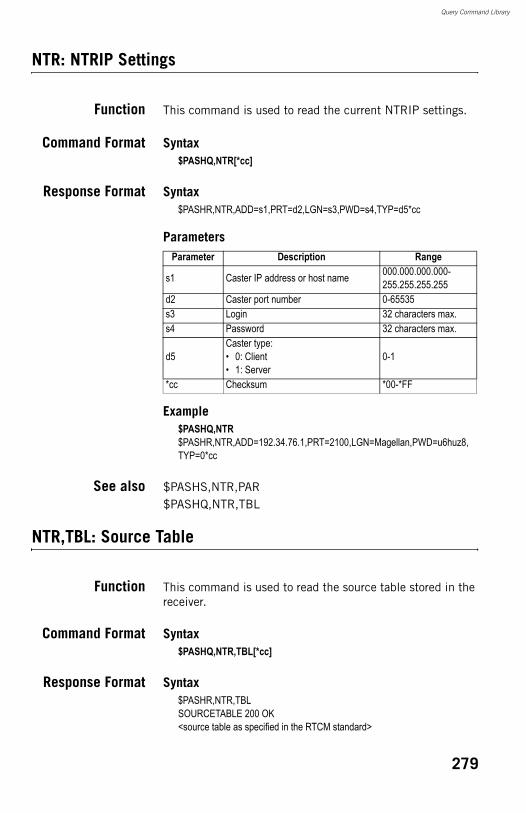
Query Command Library
NTR: NTRIP Settings
Function This command is used to read the current NTRIP settings.
Command Format Syntax$PASHQ,NTR[*cc]
Response Format Syntax$PASHR,NTR,ADD=s1,PRT=d2,LGN=s3,PWD=s4,TYP=d5*cc
Parameters
Example$PASHQ,NTR$PASHR,NTR,ADD=192.34.76.1,PRT=2100,LGN=Magellan,PWD=u6huz8,TYP=0*cc
See also $PASHS,NTR,PAR$PASHQ,NTR,TBL
NTR,TBL: Source Table
Function This command is used to read the source table stored in the receiver.
Command Format Syntax$PASHQ,NTR,TBL[*cc]
Response Format Syntax$PASHR,NTR,TBLSOURCETABLE 200 OK<source table as specified in the RTCM standard>
Parameter Description Range
s1 Caster IP address or host name 000.000.000.000-255.255.255.255
d2 Caster port number 0-65535s3 Login 32 characters max.s4 Password 32 characters max.
d5Caster type:• 0: Client• 1: Server
0-1
*cc Checksum *00-*FF
279
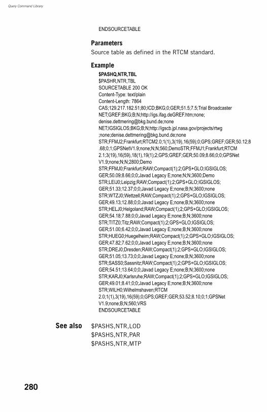
Query Command Library
ENDSOURCETABLE
ParametersSource table as defined in the RTCM standard.
Example$PASHQ,NTR,TBL$PASHR,NTR,TBLSOURCETABLE 200 OKContent-Type: text/plainContent-Length: 7864CAS;129.217.182.51;80;ICD;BKG;0;GER;51.5;7.5;Trial BroadcasterNET;GREF;BKG;B;N;http://igs.ifag.deGREF.htm;none; [email protected];noneNET;IGSIGLOS;BKG;B;N;http://igscb.jpl.nasa.gov/projects/rtwg;none;[email protected];noneSTR;FFMJ2;Frankfurt;RTCM2.0;1(1),3(19),16(59);0;GPS;GREF;GER;50.12;8.68;0;1;GPSNetV1.9;none;N;N;560;DemoSTR;FFMJ1;Frankfurt;RTCM2.1;3(19),16(59),18(1),19(1);2;GPS;GREF;GER;50.09;8.66;0;0;GPSNetV1.9;none;N;N;2800;DemoSTR;FFMJ0;Frankfurt;RAW;Compact(1);2;GPS+GLO;IGSIGLOS;GER;50.09;8.66;0;0;Javad Legacy E;none;N;N;3600;DemoSTR;LEIJ0;Leipzig;RAW;Compact(1);2;GPS+GLO;IGSIGLOS;GER;51.33;12.37;0;0;Javad Legacy E;none;B;N;3600;noneSTR;WTZJ0;Wettzell;RAW;Compact(1);2;GPS+GLO;IGSIGLOS;GER;49.13;12.88;0;0;Javad Legacy E;none;B;N;3600;noneSTR;HELJ0;Helgoland;RAW;Compact(1);2;GPS+GLO;IGSIGLOS;GER;54.18;7.88;0;0;Javad Legacy E;none;B;N;3600;noneSTR;TITZ0;Titz;RAW;Compact(1);2;GPS+GLO;IGSIGLOS;GER;51.00;6.42;0;0;Javad Legacy E;none;B;N;3600;noneSTR;HUEG0;Huegelheim;RAW;Compact(1);2;GPS+GLO;IGSIGLOS;GER;47.82;7.62;0;0;Javad Legacy E;none;B;N;3600;noneSTR;DREJ0;Dresden;RAW;Compact(1);2;GPS+GLO;IGSIGLOS;GER;51.05;13.73;0;0;Javad Legacy E;none;B;N;3600;noneSTR;SASS0;Sassnitz;RAW;Compact(1);2;GPS+GLO;IGSIGLOS;GER;54.51;13.64;0;0;Javad Legacy E;none;B;N;3600;noneSTR;KARJ0;Karlsruhe;RAW;Compact(1);2;GPS+GLO;IGSIGLOS;GER;49.01;8.41;0;0;Javad Legacy E;none;B;N;3600;noneSTR;WILH0;Wilhelmshaven;RTCM2.0;1(1),3(19),16(59);0;GPS;GREF;GER;53.52;8.10;0;1;GPSNetV1.9;none;B;N;560;VRSENDSOURCETABLE
See also $PASHS,NTR,LOD$PASHS,NTR,PAR$PASHS,NTR,MTP
280
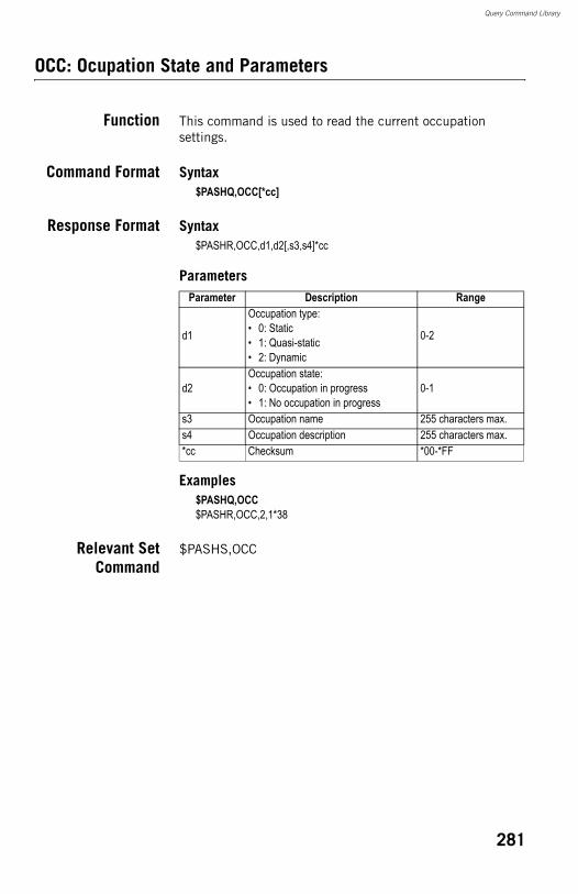
Query Command Library
OCC: Ocupation State and Parameters
Function This command is used to read the current occupation settings.
Command Format Syntax$PASHQ,OCC[*cc]
Response Format Syntax$PASHR,OCC,d1,d2[,s3,s4]*cc
Parameters
Examples$PASHQ,OCC$PASHR,OCC,2,1*38
Relevant SetCommand
$PASHS,OCC
Parameter Description Range
d1
Occupation type:• 0: Static• 1: Quasi-static• 2: Dynamic
0-2
d2Occupation state:• 0: Occupation in progress• 1: No occupation in progress
0-1
s3 Occupation name 255 characters max.s4 Occupation description 255 characters max.*cc Checksum *00-*FF
281
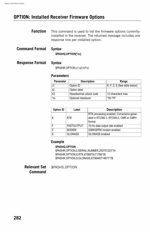
Query Command Library
OPTION: Installed Receiver Firmware Options
Function This command is used to list the firmware options currently installed in the receiver. The returned message includes one response line per installed option.
Command Format Syntax$PASHQ,OPTION[*cc]
Response Format Syntax$PASHR,OPTION,c1,s2,h3*cc
Parameters
Example$PASHQ,OPTION$PASHR,OPTION,0,SERIAL,NUMBER,200751223*7A$PASHR,OPTION,K,RTK,6756975c71766*36 $PASHR,OPTION,S,GLONASS,6756945714671*7B
Relevant SetCommand
$PASHS,OPTION
Parameter Description Rangec1 Option ID K, F, Z, S (See table below)s2 Option labelh3 Hexadecimal unlock code 13 characters max.*cc Optional checksum *00-*FF
Option ID Label Description
K RTKRTK processing enabled. Corrections gener-ated in RTCM2.3, RTCM3.0, CMR or CMR+ format.
F FASTOUTPUT 10-Hz data output rate enabledZ MODEM GSM/GPRS modem enabledS GLONASS GLONASS enabled
282
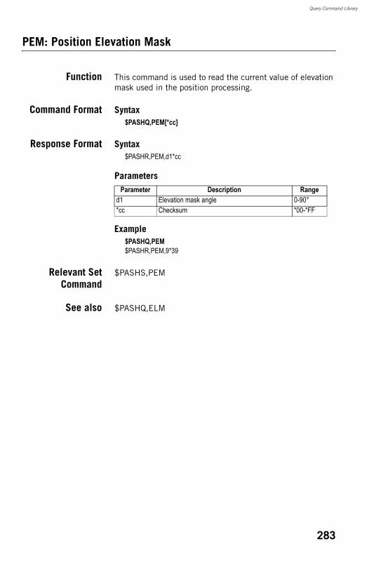
Query Command Library
PEM: Position Elevation Mask
Function This command is used to read the current value of elevation mask used in the position processing.
Command Format Syntax$PASHQ,PEM[*cc]
Response Format Syntax$PASHR,PEM,d1*cc
Parameters
Example$PASHQ,PEM$PASHR,PEM,9*39
Relevant SetCommand
$PASHS,PEM
See also $PASHQ,ELM
Parameter Description Ranged1 Elevation mask angle 0-90°*cc Checksum *00-*FF
283
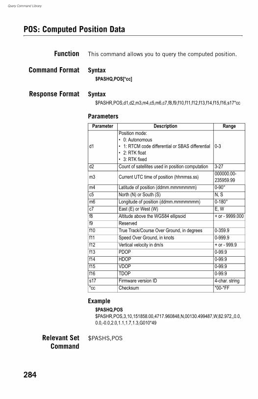
Query Command Library
POS: Computed Position Data
Function This command allows you to query the computed position.
Command Format Syntax$PASHQ,POS[*cc]
Response Format Syntax$PASHR,POS,d1,d2,m3,m4,c5,m6,c7,f8,f9,f10,f11,f12,f13,f14,f15,f16,s17*cc
Parameters
Example$PASHQ,POS$PASHR,POS,3,10,151858.00,4717.960848,N,00130.499487,W,82.972,,0.0,0.0,-0.0,2.0,1.1,1.7,1.3,G010*49
Relevant SetCommand
$PASHS,POS
Parameter Description Range
d1
Position mode:• 0: Autonomous• 1: RTCM code differential or SBAS differential• 2: RTK float• 3: RTK fixed
0-3
d2 Count of satellites used in position computation 3-27
m3 Current UTC time of position (hhmmss.ss) 000000.00-235959.99
m4 Latitude of position (ddmm.mmmmmmm) 0-90°c5 North (N) or South (S) N, Sm6 Longitude of position (ddmm.mmmmmmm) 0-180°c7 East (E) or West (W) E, Wf8 Altitude above the WGS84 ellipsoid + or - 9999.000f9 Reservedf10 True Track/Course Over Ground, in degrees 0-359.9f11 Speed Over Ground, in knots 0-999.9f12 Vertical velocity in dm/s + or - 999.9f13 PDOP 0-99.9f14 HDOP 0-99.9f15 VDOP 0-99.9f16 TDOP 0-99.9s17 Firmware version ID 4-char. string*cc Checksum *00-*FF
284
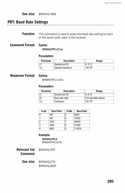
Query Command Library
See also $PASHS,NME
PRT: Baud Rate Settings
Function This command is used to query the baud rate setting for each of the serial ports used in the receiver.
Command Format Syntax$PASHQ,PRT,c1[*cc]
Parameters
Response Format Syntax$PASHR,PRT,c1,d2*cc
Parameters
Example$PASHQ,PRT,A$PASHR,PRT,A,6*55
Relevant SetCommand
$PASHS,PRT
See also $PASHQ,CTS$PASHQ,MDP
Parameter Description Rangec1 Queried port ID A, D, E*cc Optional checksum *00-*FF
Parameter Description Rangec1 Queried port ID A, D, Ed2 Baud rate code 0-9 (see table below)*cc Checksum *00-*FF
Code Baud Rate Code Baud Rate0 300 5 96001 600 6 192002 1200 7 384003 2400 8 576004 4800 9 115200
285
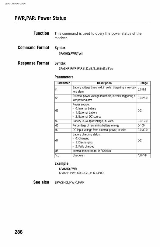
Query Command Library
PWR,PAR: Power Status
Function This command is used to query the power status of the receiver.
Command Format Syntax$PASHQ,PWR[*cc]
Response Format Syntax$PASHR,PWR,PAR,f1,f2,d3,f4,d5,f6,d7,d8*cc
Parameters
Example$PASHQ,PWR$PASHR,PWR,6.8,9.1,2,,,11.6,,44*0D
See also $PASHS,PWR,PAR
Parameter Description Range
f1 Battery voltage threshold, in volts, triggering a low-bat-tery alarm 6.7-8.4
f2 External power voltage threshold, in volts, triggering a low-power alarm 9.0-28.0
d3
Power source:• 0: Internal battery• 1: External battery• 2: External DC source
0-2
f4 Battery DC output voltage, in volts 0.0-12.0d5 Percentage of remaining battery energy 0-100f6 DC input voltage from external power, in volts 0.0-30.0
d7
Battery charging status:• 0: Charging• 1: Discharging• 2: Fully charged
0-2
d8 Internal temperature, in °Celsius*cc Checksum *00-*FF
286
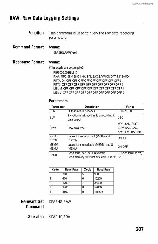
Query Command Library
RAW: Raw Data Logging Settings
Function This command is used to query the raw data recording parameters.
Command Format Syntax$PASHQ,RAW[*cc]
Response Format Syntax(Through an example):
PER:020.00 ELM:10RAW: MPC SNV SNG SNW SAL SAG SAW ION DAT INF BAUDPRTA: ON OFF OFF OFF OFF OFF OFF OFF OFF OFF 6PRTC: OFF OFF OFF OFF OFF OFF OFF OFF OFF OFF 6MEMM: OFF OFF OFF OFF OFF OFF OFF OFF OFF OFF 1MEMU: OFF OFF OFF OFF OFF OFF OFF OFF OFF OFF 0
Parameters
Relevant SetCommand
$PASHS,RAW
See also $PASHS,SBA
Parameter Description RangePER Output rate, in seconds 0.00-999.00
ELM Elevation mask used in data recording & data output 0-90
RAW Raw data typeMPC, SNV, SNG, SNW, SAL, SAG, SAW, ION, DAT, INF
PRTAPRTC
Labels for serial ports A (PRTA) and C (PRTC) ON, OFF
MEMMMEMU
Labels for memories M (MEMM) and U (MEMU) ON-OFF
BAUD For a serial port, baud rate codeFor a memory, “0” if not available, else “1”
0-9 (see table below)0-1
Code Baud Rate Code Baud Rate0 300 5 96001 600 6 192002 1200 7 384003 2400 8 576004 4800 9 115200
287
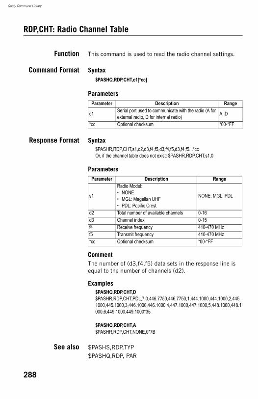
Query Command Library
RDP,CHT: Radio Channel Table
Function This command is used to read the radio channel settings.
Command Format Syntax$PASHQ,RDP,CHT,c1[*cc]
Parameters
Response Format Syntax$PASHR,RDP,CHT,s1,d2,d3,f4,f5,d3,f4,f5,d3,f4,f5...*ccOr, if the channel table does not exist: $PASHR,RDP,CHT,s1,0
Parameters
CommentThe number of (d3,f4,f5) data sets in the response line is equal to the number of channels (d2).
Examples$PASHQ,RDP,CHT,D$PASHR,RDP,CHT,PDL,7,0,446.7750,446.7750,1,444.1000,444.1000,2,445.1000,445.1000,3,446.1000,446.1000,4,447.1000,447.1000,5,448.1000,448.1000,6,449.1000,449.1000*35
$PASHQ,RDP,CHT,A$PASHR,RDP,CHT,NONE,0*7B
See also $PASHS,RDP,TYP$PASHQ,RDP, PAR
Parameter Description Range
c1 Serial port used to communicate with the radio (A for external radio, D for internal radio) A, D
*cc Optional checksum *00-*FF
Parameter Description Range
s1
Radio Model:• NONE• MGL: Magellan UHF• PDL: Pacific Crest
NONE, MGL, PDL
d2 Total number of available channels 0-16d3 Channel index 0-15f4 Receive frequency 410-470 MHzf5 Transmit frequency 410-470 MHz*cc Optional checksum *00-*FF
288
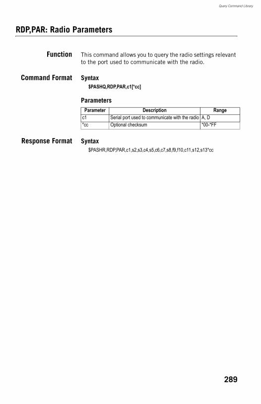
Query Command Library
RDP,PAR: Radio Parameters
Function This command allows you to query the radio settings relevant to the port used to communicate with the radio.
Command Format Syntax$PASHQ,RDP,PAR,c1[*cc]
Parameters
Response Format Syntax$PASHR,RDP,PAR,c1,s2,s3,c4,s5,c6,c7,s8,f9,f10,c11,s12,s13*cc
Parameter Description Rangec1 Serial port used to communicate with the radio A, D*cc Optional checksum *00-*FF
289
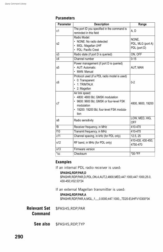
Query Command Library
Parameters
ExamplesIf an internal PDL radio receiver is used:
$PASHQ,RDP,PAR,D$PASHR,RDP,PAR,D,PDL,ON,4,AUT,2,4800,MED,447.1000,447.1000,25.0,430-450,V02.53*24
If an external Magellan transmitter is used:$PASHQ,RDP,PAR,A$PASHR,RDP,PAR,A,MGL,,1,,,,,0.0000,447.1000,,,TD20-EUHFV10300*04
Relevant SetCommand
$PASHS,RDP,PAR
See also $PASHS,RDP,TYP
Parameter Description Range
c1 The port ID you specified in the command is reminded in this field A, D
s2
Radio Model:• NONE: No radio detected• MGL: Magellan UHF• PDL: Pacific Crest
NONE,PDL, MLG (port A)PDL (port D)
s3 Radio state (if port D is queried) ON, OFFc4 Channel number 0-15
s5Power management (if port D is queried)• AUT: Automatic • MAN: Manual
AUT, MAN
c6
Protocol used (if a PDL radio model is used)• 0: Transparent • 1: TRIMTALK• 2: Magellan
0-2
c7
Air link speed:• 4800: 4800 Bd, GMSK modulation • 9600: 9600 Bd, GMSK or four-level FSK
modulation• 19200: 19200 Bd, four-level FSK modula-
tion
4800, 9600, 19200
s8 Radio sensitivity LOW, MED, HIG, OFF
f9 Receiver frequency, in MHz 410-470f10 Transmit frequency, in MHz 410-470c11 Channel spacing, in kHz (for PDL only) 12.5, 25
s12 RF band, in MHz (for PDL only) 410-430, 430-450, 4750-470
s13 Firmware version*cc Checksum *00-*FF
290
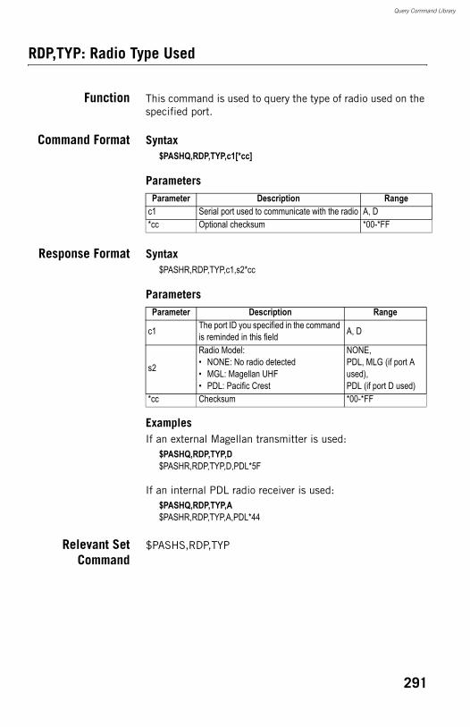
Query Command Library
RDP,TYP: Radio Type Used
Function This command is used to query the type of radio used on the specified port.
Command Format Syntax$PASHQ,RDP,TYP,c1[*cc]
Parameters
Response Format Syntax$PASHR,RDP,TYP,c1,s2*cc
Parameters
ExamplesIf an external Magellan transmitter is used:
$PASHQ,RDP,TYP,D$PASHR,RDP,TYP,D,PDL*5F
If an internal PDL radio receiver is used:$PASHQ,RDP,TYP,A$PASHR,RDP,TYP,A,PDL*44
Relevant SetCommand
$PASHS,RDP,TYP
Parameter Description Rangec1 Serial port used to communicate with the radio A, D*cc Optional checksum *00-*FF
Parameter Description Range
c1 The port ID you specified in the command is reminded in this field A, D
s2
Radio Model:• NONE: No radio detected• MGL: Magellan UHF• PDL: Pacific Crest
NONE,PDL, MLG (if port A used),PDL (if port D used)
*cc Checksum *00-*FF
291
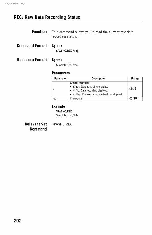
Query Command Library
REC: Raw Data Recording Status
Function This command allows you to read the current raw data recording status.
Command Format Syntax$PASHQ,REC[*cc]
Response Format Syntax$PASHR,REC,c*cc
Parameters
Example$PASHQ,REC$PASHR,REC,N*42
Relevant SetCommand
$PASHS,REC
Parameter Description Range
c
Control character:• Y: Yes. Data recording enabled.• N: No. Data recording disabled.• S: Stop. Data recorded enabled but stopped.
Y, N, S
*cc Checksum *00-*FF
292
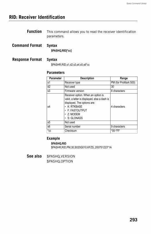
Query Command Library
RID: Receiver Identification
Function This command allows you to read the receiver identification parameters.
Command Format Syntax$PASHQ,RID[*cc]
Response Format Syntax$PASHR,RID,s1,d2,s3,s4,s5,s6*cc
Parameters
Example$PASHQ,RID$PASHR,RID,PM,30,S020G010,KFZS,,200751223*1A
See also $PASHQ,VERSION$PASHQ,OPTION
Parameter Description Ranges1 Receiver type PM (for ProMark 500)d2 Not used 30s3 Firmware version 8 characters
s4
Receiver option. When an option is valid, a letter is displayed, else a dash is displayed. The options are: • K: RTKBASE• F: FASTOUTPUT• Z: MODEM• S: GLONASS
4 characters
s5 Not useds6 Serial number 9 characters*cc Checksum *00-*FF
293
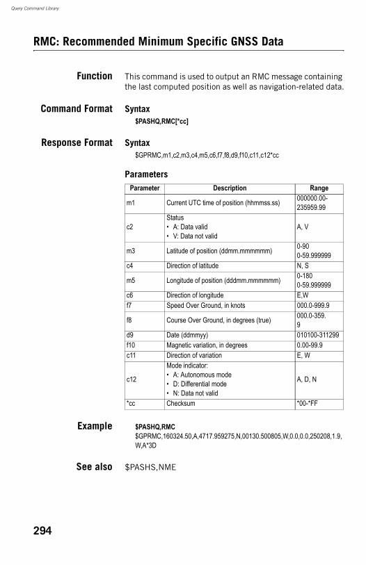
Query Command Library
RMC: Recommended Minimum Specific GNSS Data
Function This command is used to output an RMC message containing the last computed position as well as navigation-related data.
Command Format Syntax$PASHQ,RMC[*cc]
Response Format Syntax$GPRMC,m1,c2,m3,c4,m5,c6,f7,f8,d9,f10,c11,c12*cc
Parameters
Example $PASHQ,RMC$GPRMC,160324.50,A,4717.959275,N,00130.500805,W,0.0,0.0,250208,1.9,W,A*3D
See also $PASHS,NME
Parameter Description Range
m1 Current UTC time of position (hhmmss.ss) 000000.00-235959.99
c2Status• A: Data valid• V: Data not valid
A, V
m3 Latitude of position (ddmm.mmmmmm) 0-900-59.999999
c4 Direction of latitude N, S
m5 Longitude of position (dddmm.mmmmmm) 0-1800-59.999999
c6 Direction of longitude E,Wf7 Speed Over Ground, in knots 000.0-999.9
f8 Course Over Ground, in degrees (true) 000.0-359.9
d9 Date (ddmmyy) 010100-311299f10 Magnetic variation, in degrees 0.00-99.9c11 Direction of variation E, W
c12
Mode indicator:• A: Autonomous mode• D: Differential mode• N: Data not valid
A, D, N
*cc Checksum *00-*FF
294
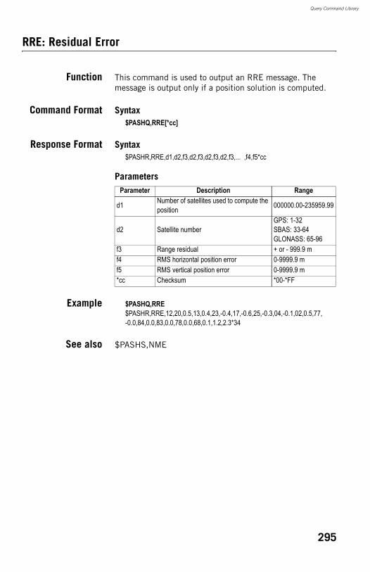
Query Command Library
RRE: Residual Error
Function This command is used to output an RRE message. The message is output only if a position solution is computed.
Command Format Syntax$PASHQ,RRE[*cc]
Response Format Syntax$PASHR,RRE,d1,d2,f3,d2,f3,d2,f3,d2,f3,... ,f4,f5*cc
Parameters
Example $PASHQ,RRE$PASHR,RRE,12,20,0.5,13,0.4,23,-0.4,17,-0.6,25,-0.3,04,-0.1,02,0.5,77,-0.0,84,0.0,83,0.0,78,0.0,68,0.1,1.2,2.3*34
See also $PASHS,NME
Parameter Description Range
d1 Number of satellites used to compute the position 000000.00-235959.99
d2 Satellite numberGPS: 1-32SBAS: 33-64GLONASS: 65-96
f3 Range residual + or - 999.9 mf4 RMS horizontal position error 0-9999.9 mf5 RMS vertical position error 0-9999.9 m*cc Checksum *00-*FF
295
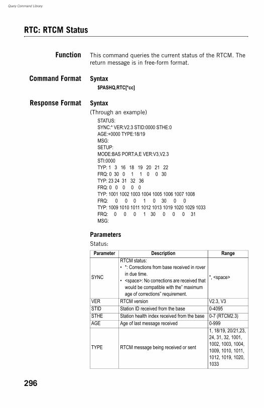
Query Command Library
RTC: RTCM Status
Function This command queries the current status of the RTCM. The return message is in free-form format.
Command Format Syntax$PASHQ,RTC[*cc]
Response Format Syntax(Through an example)
STATUS:SYNC:* VER:V2.3 STID:0000 STHE:0AGE:+0000 TYPE:18/19MSG:SETUP:MODE:BAS PORT:A,E VER:V3,V2.3STI:0000TYP: 1 3 16 18 19 20 21 22FRQ: 0 30 0 1 1 0 0 30TYP: 23 24 31 32 36FRQ: 0 0 0 0 0TYP: 1001 1002 1003 1004 1005 1006 1007 1008FRQ: 0 0 0 1 0 30 0 0TYP: 1009 1010 1011 1012 1013 1019 1020 1029 1033FRQ: 0 0 0 1 30 0 0 0 31MSG:
ParametersStatus:
Parameter Description Range
SYNC
RTCM status:• *: Corrections from base received in rover
in due time.• <space>: No corrections are received that
would be compatible with the” maximum age of corrections” requirement.
*, <space>
VER RTCM version V2.3, V3STID Station ID received from the base 0-4095STHE Station health index received from the base 0-7 (RTCM2.3)AGE Age of last message received 0-999
TYPE RTCM message being received or sent
1, 18/19, 20/21,23, 24, 31, 32, 1001, 1002, 1003, 1004, 1009, 1010, 1011, 1012, 1019, 1020, 1033
296
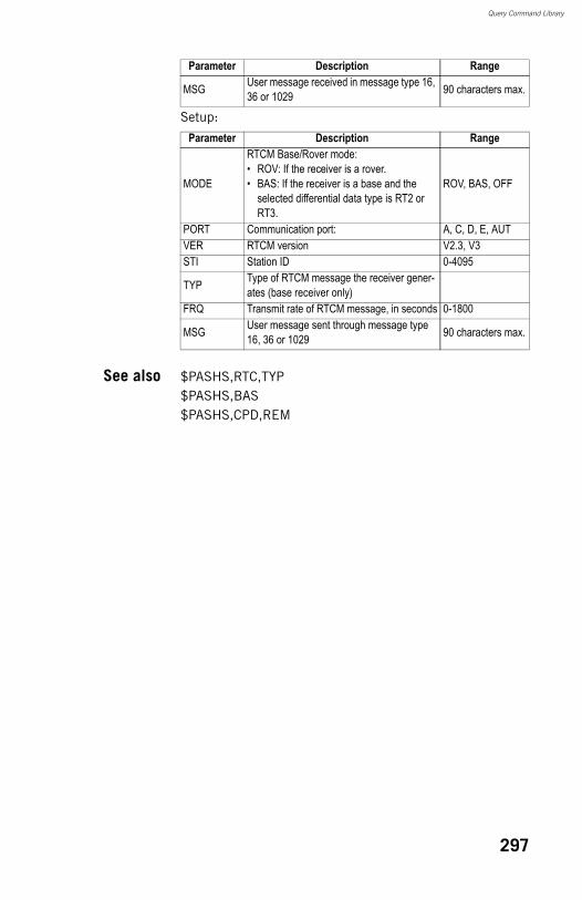
Query Command Library
Setup:
See also $PASHS,RTC,TYP$PASHS,BAS$PASHS,CPD,REM
MSG User message received in message type 16, 36 or 1029 90 characters max.
Parameter Description Range
MODE
RTCM Base/Rover mode:• ROV: If the receiver is a rover.• BAS: If the receiver is a base and the
selected differential data type is RT2 or RT3.
ROV, BAS, OFF
PORT Communication port: A, C, D, E, AUTVER RTCM version V2.3, V3STI Station ID 0-4095
TYP Type of RTCM message the receiver gener-ates (base receiver only)
FRQ Transmit rate of RTCM message, in seconds 0-1800
MSG User message sent through message type 16, 36 or 1029 90 characters max.
Parameter Description Range
297
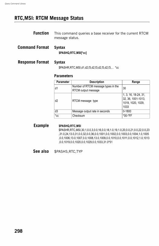
Query Command Library
RTC,MSI: RTCM Message Status
Function This command queries a base receiver for the current RTCM message status.
Command Format Syntax$PASHQ,RTC,MSI[*cc]
Response Format Syntax$PASHR,RTC,MSI,d1,d2,f3,d2,f3,d2,f3,d2,f3,... *cc
Parameters
Example $PASHQ,RTC,MSI$PASHR,RTC,MSI,30,1,0.0,3,0.0,16,0.0,18,1.0,19,1.0,20,0.0,21,0.0,22,0.0,23,31.0,24,13.0,31,0.0,32,0.0,36,0.0,1001,0.0,1002,0.0,1003,0.0,1004,1.0,1005,0.0,1006,13.0,1007,0.0,1008,13.0,1009,0.0,1010,0.0,1011,0.0,1012,1.0,1013,0.0,1019,0.0,1020,0.0,1029,0.0,1033,31.0*51
See also $PASHS,RTC,TYP
Parameter Description Range
d1 Number of RTCM message types in the RTCM output message 30
d2 RTCM message type
1, 3, 16, 18-24, 31, 32, 36, 1001-1013, 1019, 1020, 1029, 1033
d3 Message output rate in seconds 0-1800*cc Checksum *00-*FF
298
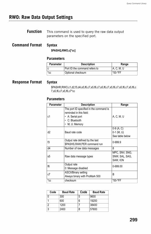
Query Command Library
RWO: Raw Data Output Settings
Function This command is used to query the raw data output parameters on the specified port.
Command Format Syntax$PASHQ,RWO,c[*cc]
Parameters
Response Format Syntax$PASHR,RWO,c1,d2,f3,d4,s5,f6,c7,s5,f6,c7,s5,f6,c7,s5,f6,c7,s5,f6,c7,s5,f6,c7,s5,f6,c7,s5,f6,c7*cc
Parameters
Parameter Description Rangec Port ID the command refers to A, C, M, U*cc Optional checksum *00-*FF
Parameter Description Range
c1
The port ID specified in the command is reminded in this field:• A: Serial port• C: Bluetooth• M, U: Memory
A, C, M, U
d2 Baud rate code0-9 (A, C)0-1 (M, U)See table below
f3 Output rate defined by the last $PASHS,RAW,PER command run 0-999.9
d4 Number of raw data messages 8
s5 Raw data message typesMPC, SNV, SNG, SNW, SAL, SAG, SAW, ION
f6 Output rate0: Message disabled 0-999.00
c7 ASCII/Binary settingAlways binary with ProMark 500 B
*cc checksum *00-*FF
Code Baud Rate Code Baud Rate0 300 5 96001 600 6 192002 1200 7 384003 2400 8 57600
299

Query Command Library
Example$PASHQ,RWO,A$PASHR,RWO,A,6,001.00,8,MPC,0.00,B,SNV,0.00,B,SNG,0.00,B,SNW,0.00,B,SAL,0.00,B,SAG,0.00,B,SAW,0.00,B,ION,0.00,B*6D
See also $PASHQ,RAW
4 4800 9 115200Code Baud Rate Code Baud Rate
300
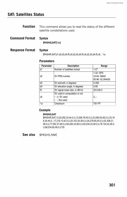
Query Command Library
SAT: Satellites Status
Function This command allows you to read the status of the different satellite constellations used.
Command Format Syntax$PASHQ,SAT[*cc]
Response Format Syntax$PASHR,SAT,d1,d2,d3,d4,f5,c6,d2,d3,d4,f5,c6,d2,d3,d4,f5,c6... *cc
Parameters
Example$PASHQ,SAT$PASHR,SAT,13,20,092,32,44.0,U,13,206,78,50.0,U,23,056,55,48.0,U,33,198,34,44.0,-,17,218,13,42.0,U,25,152,34,38.0,U,04,276,65,50.0,U,02,308,31,48.0,U,77,052,37,48.0,U,84,294,33,48.0,U,83,234,23,48.0,U,78,124,42,46.0,U,68,034,65,48.0,U*35
See also $PASHS,NME
Parameter Description Ranged1 Number of satellites locked 1-27
d2 SV PRN number1-32: GPS33-64: SBAS65-96: GLONASS
d3 SV azimuth, in degrees 0-359d4 SV elevation angle, in degrees 0-90f5 SV signal-noise ratio, in dB.Hz 30.0-60.0
c6SV used in computation or not• U: SV used• -: Not used
U, -
*cc Checksum *00-*FF
301
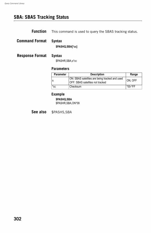
Query Command Library
SBA: SBAS Tracking Status
Function This command is used to query the SBAS tracking status.
Command Format Syntax$PASHQ,SBA[*cc]
Response Format Syntax$PASHR,SBA,s*cc
Parameters
Example$PASHQ,SBA$PASHR,SBA,ON*09
See also $PASHS,SBA
Parameter Description Range
s ON: SBAS satellites are being tracked and usedOFF: SBAS satellites not tracked ON, OFF
*cc Checksum *00-*FF
302
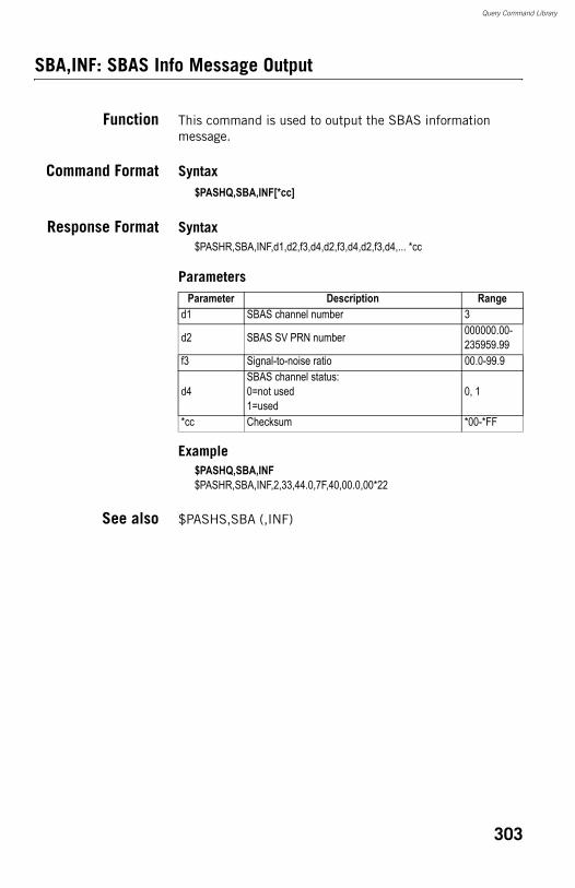
Query Command Library
SBA,INF: SBAS Info Message Output
Function This command is used to output the SBAS information message.
Command Format Syntax$PASHQ,SBA,INF[*cc]
Response Format Syntax$PASHR,SBA,INF,d1,d2,f3,d4,d2,f3,d4,d2,f3,d4,... *cc
Parameters
Example$PASHQ,SBA,INF$PASHR,SBA,INF,2,33,44.0,7F,40,00.0,00*22
See also $PASHS,SBA (,INF)
Parameter Description Ranged1 SBAS channel number 3
d2 SBAS SV PRN number 000000.00-235959.99
f3 Signal-to-noise ratio 00.0-99.9
d4SBAS channel status:0=not used1=used
0, 1
*cc Checksum *00-*FF
303
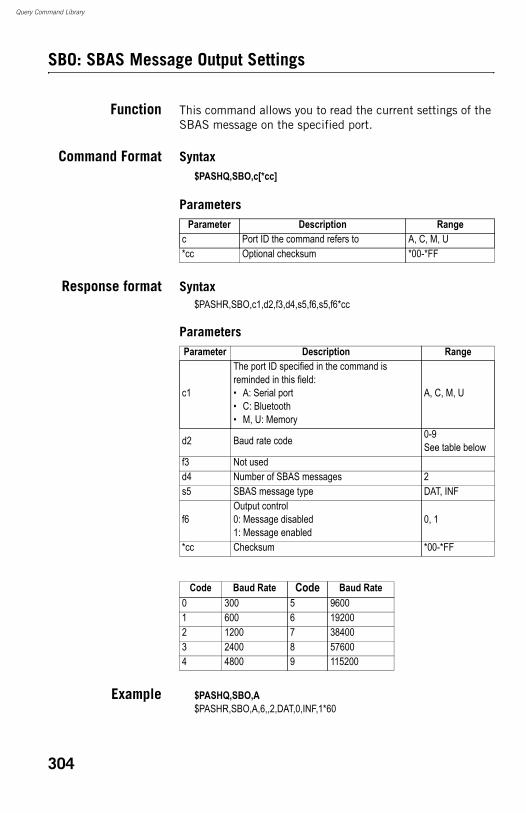
Query Command Library
SBO: SBAS Message Output Settings
Function This command allows you to read the current settings of the SBAS message on the specified port.
Command Format Syntax$PASHQ,SBO,c[*cc]
Parameters
Response format Syntax$PASHR,SBO,c1,d2,f3,d4,s5,f6,s5,f6*cc
Parameters
Example $PASHQ,SBO,A$PASHR,SBO,A,6,,2,DAT,0,INF,1*60
Parameter Description Rangec Port ID the command refers to A, C, M, U*cc Optional checksum *00-*FF
Parameter Description Range
c1
The port ID specified in the command is reminded in this field:• A: Serial port• C: Bluetooth• M, U: Memory
A, C, M, U
d2 Baud rate code 0-9See table below
f3 Not usedd4 Number of SBAS messages 2s5 SBAS message type DAT, INF
f6Output control0: Message disabled1: Message enabled
0, 1
*cc Checksum *00-*FF
Code Baud Rate Code Baud Rate0 300 5 96001 600 6 192002 1200 7 384003 2400 8 576004 4800 9 115200
304
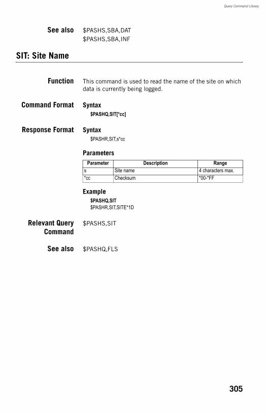
Query Command Library
See also $PASHS,SBA,DAT$PASHS,SBA,INF
SIT: Site Name
Function This command is used to read the name of the site on which data is currently being logged.
Command Format Syntax$PASHQ,SIT[*cc]
Response Format Syntax$PASHR,SIT,s*cc
Parameters
Example$PASHQ,SIT$PASHR,SIT,SITE*1D
Relevant QueryCommand
$PASHS,SIT
See also $PASHQ,FLS
Parameter Description Ranges Site name 4 characters max.*cc Checksum *00-*FF
305
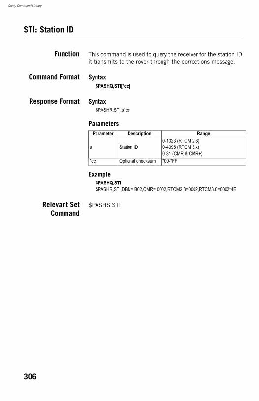
Query Command Library
STI: Station ID
Function This command is used to query the receiver for the station ID it transmits to the rover through the corrections message.
Command Format Syntax$PASHQ,STI[*cc]
Response Format Syntax$PASHR,STI,s*cc
Parameters
Example$PASHQ,STI$PASHR,STI,DBN= B02,CMR= 0002,RTCM2.3=0002,RTCM3.0=0002*4E
Relevant SetCommand
$PASHS,STI
Parameter Description Range
s Station ID0-1023 (RTCM 2.3)0-4095 (RTCM 3.x)0-31 (CMR & CMR+)
*cc Optional checksum *00-*FF
306
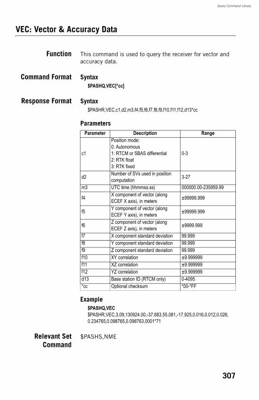
Query Command Library
VEC: Vector & Accuracy Data
Function This command is used to query the receiver for vector and accuracy data.
Command Format Syntax$PASHQ,VEC[*cc]
Response Format Syntax$PASHR,VEC,c1,d2,m3,f4,f5,f6,f7,f8,f9,f10,f11,f12,d13*cc
Parameters
Example$PASHQ,VEC$PASHR,VEC,3,09,130924.00,-37.683,55.081,-17.925,0.016,0.012,0.026,0.234765,0.098765,0.098763,0001*71
Relevant SetCommand
$PASHS,NME
Parameter Description Range
c1
Position mode:0: Autonomous1: RTCM or SBAS differential2: RTK float3: RTK fixed
0-3
d2 Number of SVs used in position computation 3-27
m3 UTC time (hhmmss.ss) 000000.00-235959.99
f4 X component of vector (along ECEF X axis), in meters ±99999.999
f5 Y component of vector (along ECEF Y axis), in meters ±99999.999
f6 Z component of vector (along ECEF Z axis), in meters ±9999.999
f7 X component standard deviation 99.999f8 Y component standard deviation 99.999f9 Z component standard deviation 99.999f10 XY correlation ±9.999999f11 XZ correlation ±9.999999f12 YZ correlation ±9.999999d13 Base station ID (RTCM only) 0-4095*cc Optional checksum *00-*FF
307
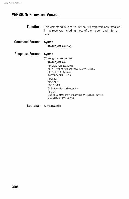
Query Command Library
VERSION: Firmware Version
Function This command is used to list the firmware versions installed in the receiver, including those of the modem and internal radio.
Command Format Syntax$PASHQ,VERSION[*cc]
Response Format Syntax(Through an example)
$PASHQ,VERSIONAPPLICATION: S024G013KERNEL: 2.6.19-pm4 #157 Wed Feb 27 15:33:55RESCUE: 2.6.19-rescueBOOT LOADER: 1.1.5.3PMU: 2.21API: 1.107BSP: 1.0-108GNSS uploader: pm4loader 0.14 RFS: 044GSM : 6.63 stack IP : WIP Soft v301 on Open AT OS v421Internal Radio: PDL V02.53
See also $PASHQ,RID
308
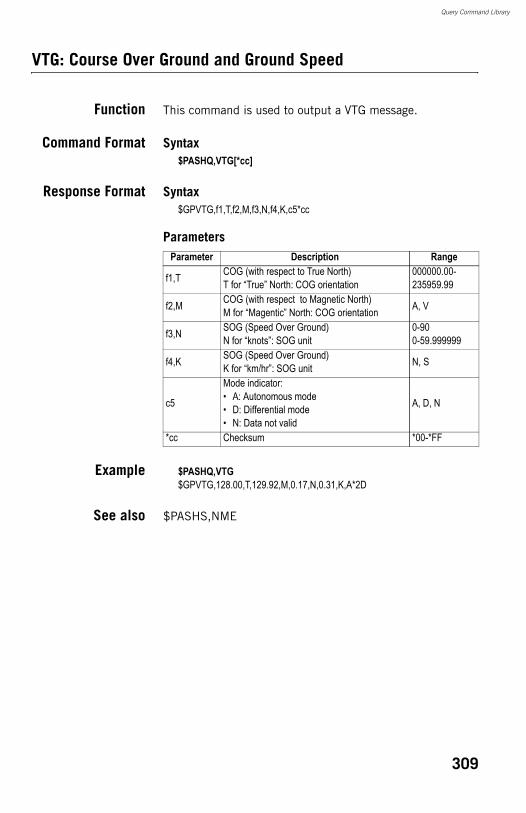
Query Command Library
VTG: Course Over Ground and Ground Speed
Function This command is used to output a VTG message.
Command Format Syntax$PASHQ,VTG[*cc]
Response Format Syntax$GPVTG,f1,T,f2,M,f3,N,f4,K,c5*cc
Parameters
Example $PASHQ,VTG$GPVTG,128.00,T,129.92,M,0.17,N,0.31,K,A*2D
See also $PASHS,NME
Parameter Description Range
f1,T COG (with respect to True North)T for “True” North: COG orientation
000000.00-235959.99
f2,M COG (with respect to Magnetic North)M for “Magentic” North: COG orientation A, V
f3,N SOG (Speed Over Ground)N for “knots”: SOG unit
0-900-59.999999
f4,K SOG (Speed Over Ground)K for “km/hr”: SOG unit N, S
c5
Mode indicator:• A: Autonomous mode• D: Differential mode• N: Data not valid
A, D, N
*cc Checksum *00-*FF
309
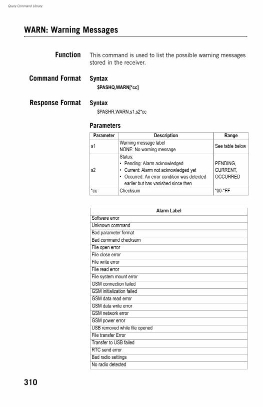
Query Command Library
WARN: Warning Messages
Function This command is used to list the possible warning messages stored in the receiver.
Command Format Syntax$PASHQ,WARN[*cc]
Response Format Syntax$PASHR,WARN,s1,s2*cc
ParametersParameter Description Range
s1 Warning message labelNONE: No warning message See table below
s2
Status:• Pending: Alarm acknowledged• Current: Alarm not acknowledged yet• Occurred: An error condition was detected
earlier but has vanished since then
PENDING, CURRENT, OCCURRED
*cc Checksum *00-*FF
Alarm LabelSoftware errorUnknown commandBad parameter formatBad command checksumFile open errorFile close errorFile write errorFile read errorFile system mount errorGSM connection failedGSM initialization failedGSM data read errorGSM data write errorGSM network errorGSM power errorUSB removed while file openedFile transfer ErrorTransfer to USB failedRTC send errorBad radio settingsNo radio detected
310
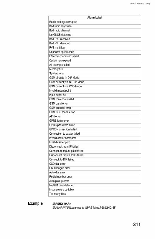
Query Command Library
Example $PASHQ,WARN$PASHR,WARN,connect. to GPRS failed,PENDING*5F
Radio settings corruptedBad radio responseBad radio channelNo GNSS detectedBad PVT receivedBad PVT decodedPVT multiflagUnknown option codeC3 code checksum is badOption has expiredAll attempts failedMemory fullSpy too longGSM already in DIP ModeGSM currently in NTRIP ModeGSM currently in CSD ModeInvalid mount pointInput buffer fullGSM Pin code invalidGSM band errorGSM protocol errorGSM CSD mode errorAPN errorGPRS login errorGPRS password errorGPRS connection failedConnection to caster failedInvalid caster hostnameInvalid caster portDisconnect. from IP failedConnect. to mount point failedDisconnect. from GPRS failedConnect. to DIP failedCSD dial errorCSD hangup errorAuto dial errorRedial number errorAuto pickup errorNo SIM card detectedIncomplete srce tableToo many files
Alarm Label
311
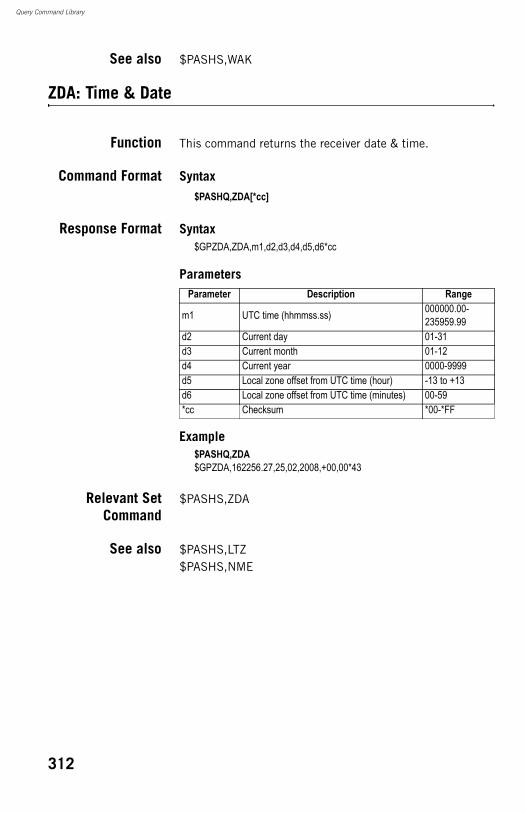
Query Command Library
See also $PASHS,WAK
ZDA: Time & Date
Function This command returns the receiver date & time.
Command Format Syntax$PASHQ,ZDA[*cc]
Response Format Syntax$GPZDA,ZDA,m1,d2,d3,d4,d5,d6*cc
Parameters
Example$PASHQ,ZDA$GPZDA,162256.27,25,02,2008,+00,00*43
Relevant SetCommand
$PASHS,ZDA
See also $PASHS,LTZ$PASHS,NME
Parameter Description Range
m1 UTC time (hhmmss.ss) 000000.00-235959.99
d2 Current day 01-31d3 Current month 01-12d4 Current year 0000-9999d5 Local zone offset from UTC time (hour) -13 to +13d6 Local zone offset from UTC time (minutes) 00-59*cc Checksum *00-*FF
312
Index
AAbsolute positioning 83Absolute, centimeter-accurate positioning 83AC/DC power supply kit 2Accuracy 18, 95Acknowlege (alarm) 145Active Sync 25ActiveSync 44, 53Age of corrections 105, 112Alarm status 13Alarms 8, 145Almanac 128Ambiguity fixing 38, 152Angle 28Angle Entry and Display 28Antenna characteristics 11Antenna extension 3Antenna height 35, 38Antenna parameters 168Antenna reduction 55APN 41ARP 92ATOM 19ATOM files 151AUTO 12Auto by interval 52Auto-dial 109BBacklight 8Band (GSM) 41BASE 12Base data 71Base ID 35Base location 82Base position 83, 153Base settings 168Base/rover configuration 70Baseline 70, 76Battery 20Battery (external) 31Battery (insert) 17Battery (remove) 16Battery charger 2Battery icon 13Battery kit 20Battery model 9Beeper setting 169BLADE 1, 18Bluetooth 10, 28, 30, 34, 61, 63, 165Bluetooth connection 131
Bluetooth identifier 15Bluetooth status 14Boot sequence 131Boundary survey 123Buzzer 8CCarrier 69Carrier cycle 95Carrier phase measurements 69Carrying case 4Carrying case (rigid) 3Centimeter-level accuracy 119CEP 98Change Ant. 56Change key 26Channel 35, 38Channel spacing 107Channels 17Charging battery 16Cingular 41Closed-loop traverse 124CMR 113CMR+ 113CMR, CMR+ 19Command window 162Comms tab 29, 37Confidence level 38Configure button 34, 37Constellation 70Coordinate Display Order 28CPD 69CRD files 27CSD 105, 109DData collection 128Data collection (PP) 61Data Link 135Data link 70, 105Data link (monitoring) 111Data link icon 13Data logging 134Data transfer screen 15, 57DBEN 113DC power input 9Default settings 165Delete files 58Delete Receiver 29Device cable (USB) 2, 57DIrect IP 111Direct IP 38, 105, 109Display screen 7
Distance 27Distance mode 52, 82DOP 85, 129, 142Download positions from external device 53Duty cycle 108DXF 21EECEF 99EDGE 20Elevation 100Elevation mask 35, 38, 152Ellipsoidal height 99Epoch 116, 119Equip tab 34, 37Existing control point 123External event 19Extrapolation 116FFactory settings 11, 155, 165Fast RTK 116, 118FAST RTK mode 151FAST Survey 21, 26, 27Field bag 3Field delimiter 161Field terminal 36Find Receiver 29Firmware options 22Firmware update 11Firmware version 15FIXED 12Fixed (solution) 69FKP 19FLOAT 12Float 38Frequency band (UHF radio) 107FSK 108GGeneral Status screen 12, 55Geographic coordinates 99Geoid 100, 103Geoid(upload) 157Geoids Utility (GNSS Solutions) 157GLONASS 1, 18, 35, 38, 152GMSK 108GNSS 70GNSS reception 167GNSS Solutions 20, 44, 53, 128GPRS 36, 106GPS 17GPS base 30GPS rover 30
GPS vector 127GSF file 157GSM 105, 108, 109GSM antenna 3, 9, 36GSM module (built-in) 36GSM status 13HHeader 161Height mark 11Helmert 45, 48, 103HI measurement tape 2, 11Hopping (frequency hopping) 108Horizontal Control 47Host cable (USB) 2HRMS 140IImplementation rules 71, 77Initialization (strategies for) 86Initializer bar 87Initializing 85Install (FAST Survey) 25Instant RTK 18Instr 34, 37Integer ambiguity 85Internal radio 166Intervisible points 123, 125IP address 39ITRF00 99JJamming 137KKey combinations 11Kinematic Survey (PP) 67Kinematic survey (PP) 80Kinematic vs. Static 86Known point 87LL1 phase center 11L2 phase center 11LandXML 21Latency 116, 117, 118LED status (battery charger) 17Li-ion battery 2Line of sight 136Line-of-sight 126Link (direct) 125Local grid 101Localization 45, 101, 157Log button 8Log interval 76, 81Log Raw GPS 56, 58
Logging points (RTK) 73Logging points in continuous mode (RTK) 74Long-range radio link 31Loop (strong) 125MM memory 165MAC 19Magellan U-link transmitter 3, 4Manufacturer 34, 37Memory 19Memory Full 135Memory screens 14Message type 35Mission Planning 128Mobile Device Center 25Model (equipment) 34, 37Modem 106, 108, 165Modem (internal) 41Modulation type 108Multipath mitigation 18NNetwork 38, 41Network design 123NMEA 19NMEA messages (computed) 166NMEA messages (raw) 167NTRIP 19, 38, 43, 105, 109, 110NTRIP caster 106Number of re-dials 109OObservable 113Observation
Plan 128Times 128
Observation time 76, 86, 90Occupation time 71, 76OLED 7One-point azimuth 103Options 156OTF 87Over the Air Baud 35, 39PPac Crest transmitter 3PacCrest transmitter (connection diagram) 33Pages (of information) 8Password 39Pause/resume (data logging) 55, 56PDOP 129Phase center 92
Phase center offset 92Phone number 39Pinouts 23Pivot point 128Plane similarity 102Points in loop 125Position averaging 71Position computation 168Post-processed surveying 69Power (transmitted) 107Power button 7Power LED 7Power on 132Power settings 169Power status 13Power-on screen 12PPS (1 PPS) 19Precision 28Projection 28ProMark3 (use with) 158Protocol 35, 38QQuality (results) 128Query commands 161RRadio 105, 106Radio (license-free) 107Radio antenna 9, 36, 136Radio data rate 108Radio module 9, 36, 136, 149, 154Radio modules 20Radio range 137Radio receiver kit 3Radius (antenna radius) 92Range pole 36Raw data 8, 76Raw data icon 13Raw data logging 167Raw data recording rate 77Readings (number of) 51Receiver identification screen 15Receiver parameters 34, 38Receiver serial number 15Recording interval 19Registering FAST Survey 26Relative positioning 84Relative, centimeter-accurate positioning 84Reset Procedure 149Restore (base/rover configuration) 152Rigid body 102
rms 98Rover-only configuration 71RS232 from/to RS422 156RS422 from/to RS232 156RTCM 19, 114RTK correction data 71, 113RTK mode 38RTK output rate 121RTK position output modes 116RTK real-time surveying 69RTK vs. Post-Processing 85RW5 21SSatellite
Availability 128Distribution 128Geometry 129
Satellites in use 13Save (rover/base configuration) 152Saving registration code 27SBAS 1, 18, 35, 38, 70, 152Screen backlight 15Scroll button 7, 8, 12Send Command 162Send File 162Serial commands 161, 163Serial port 10Serial Ports 165Set commands 161Set Receiver Name 29, 37Set Receiver PIN 29Setup (PP base) 59Setup (PP rover) 59SHMP 92SHMP offset 92SHP 21SIM Card 155SIM card 36Single vs. dual-frequency 86Size 19Slant 35Slant height measurement 93Slant measurement 11Source table 106SpiderNet 43Squelch 39Stake out 48Stake points 48Staking out (RTK) 75Standalone (raw data logging) 55, 56Static Survey (PP) 63
Static survey (PP) 78Status (position) 12Stop & Go Survey (PP) 65Stop & Go survey (PP) 79Stop&Go 56Storage medium 55Store points 51TTag New Site 56Tagging 55TCP/IP 42TDMA 105Time mode 52, 82Time out 110Time settings 169Time-tagged RTK 116, 117Time-tagged RTK mode 151T-Mobile 41Too few satellites 133Total station 124Transfer rate 106Transmitter settings 35Traverse legs 126Traverse plan 124Tribrach 31Tripod 31TTFF 71, 86, 89UU memory 165UDP/IP 42Update rate 18Upload positions to external device 44USB port 10USB status 14VVertical 38Vertical Control 47Vertical control points 124Vertical height measurement 94VRMS 140VRS 19, 111WWeight 19WGS84 99WinComm 162ZZero Azimuth Setting 28

ProMark™500
Reference ManualIncludes Serial Commands Supplement
Survey Solutions Contact Information:In USA +1 408 615 3970 � Fax +1 408 615 5200Toll Free (Sales in USA/Canada) 1 800 922 2401In South America +56 2 273 3214 � Fax +56 2 273 3187Email [email protected]
In France +33 2 28 09 38 00 � Fax +33 2 28 09 39 39In Russia +7 495 980 5400 � Fax +7 495 981 4840In the Netherlands +31 78 61 57 988 � Fax +31 78 61 52 027Email [email protected]
In Singapore +65 9838 4229 � Fax +65 6777 9881In China +86 10 6566 9866 � Fax +86 10 6566 0246Email [email protected]
Magellan follows a policy of continuous product improvement; specifications and descriptions are thus subject to change without notice. Please contact Magellan for the latest product information.© 2008 Magellan Navigation, Inc. All rights reserved. ProMark is a registered trademark of Magellan Navigation, Inc. All other product and brand names are trademarks of their respective holders.P/N 631630-01A