magallanes atir - marine.gov.scot
TRANSCRIPT

Magallanes ATIR
Project Information Summary
August 2021

Title: Magallanes PIS Date: 02/08/21 i
©EMEC 2021
Document History Revision Date Description Originated
by Reviewed by
Approved by
1.0 02/08/21 For submission EMEC (DL)
Disclaimer In no event will the European Marine Energy Centre Ltd or its employees or agents, be liable to you or anyone else for any decision made or action taken in reliance on the information in this report or for any consequential, special or similar damages, even if advised of the possibility of such damages. While we have made every attempt to ensure that the information contained in the report has been obtained from reliable sources, neither the authors nor the European Marine Energy Centre Ltd accept any responsibility for and exclude all liability for damages and loss in connection with the use of the information or expressions of opinion that are contained in this report, including but not limited to any errors, inaccuracies, omissions and misleading or defamatory statements, whether direct or indirect or consequential. Whilst we believe the contents to be true and accurate as at the date of writing, we can give no assurances or warranty regarding the accuracy, currency or applicability of any of the content in relation to specific situations or particular circumstances.

Title: Magallanes PIS Date: 02/08/21 ii
©EMEC 2021
Contents 1 Introduction 1
1.2 Project background 1
1.3 Company background 1
1.4 Technology Background 2
2 Device Description 4
2.1 How it works 6
2.2 Mooring system 7
2.2.1 Temporary mooring system 10
2.3 Materials used 11
3 Project Description 14
3.1 Location 14
3.2 Installation method 16
3.2.1 Blades installation methodology 18
3.2.2 Fall of Warness mooring works 19
3.3 Operations and Maintenance Works 19
3.4 Decommissioning / removal method 20
3.5 Anticipated vessel traffic to site 20
3.6 Device monitoring systems 21
3.7 Third Party Verification (TPV) 23
4 Environmental and Navigational Risk Considerations 24

Title: Magallanes PIS Date: 02/08/21 iii
©EMEC 2021
List of Figures Figure 1. Device launch in Vigo ................................................................................................. 3
Figure 2. Scheme of block distribution ...................................................................................... 4
Figure 3. Main components of the mechanical system ............................................................. 5
Figure 4. Indicative overall dimensions of the platform ............................................................. 5
Figure 5. Diagram of electrical power generation from tidal currents ....................................... 7
Figure 6. Scheme of umbilical cable entering the platform ....................................................... 7
Figure 7. Proposed mooring system.......................................................................................... 8
Figure 8. Scheme of mooring system ........................................................................................ 9
Figure 9. Single point mooring system schematic prior to device installation (Above), and
during deployment (Below) ...................................................................................................... 11
Figure 10. Chart showing the area of EMEC Fall of Warness test site. Magallanes Crown
Estate lease outlined with solid red line. Moorings shown in blue. Fall of Warness tidal test
site Crown Estate lease shown as dashed red line ................................................................ 14
Figure 11. The device will be deployed at test berth 1............................................................ 15
Figure 12. Detailed schematic encompassing other berths, with the maximum academic
excursion following any single failuer event of the mooring legs ............................................ 15
Figure 13. Map showing area of EMEC's scale tidal test site, Shapinsay Sound .................. 16
Figure 14. Map showing area of device temporary deployment at Deerness Sound ............ 17
List of Tables Table 1. Main specifications of the platform .............................................................................. 6
Table 2. Deployment location at EMEC's Fall of Warness test site ........................................ 16
Table 3. Attachment points at EMEC’s Shapinsay Sound test site ........................................ 16
Table 4. Boundary of lease area for temporary mooring at Deerness anchorage ................. 17
Table 5. Operational activities and anticipated frequency of vessel movements ................... 20
Table 6. Platform monitoring systems ..................................................................................... 21

Title: Magallanes PIS: Date: 02/08/21
©EMEC 2021
1 Introduction 1.2 Project background
The predictability of tidal energy makes it one of the most interesting and commercially viable
forms of renewable energy sources. Furthermore, water is around 1000 times denser than air, thus allowing tidal turbines to be significantly smaller than wind turbines while still capturing an equivalent amount of energy. Magallanes Renovables S.L. (the ‘Company’) therefore
decided to develop a high stability floating platform (ATIR) that has a generating capacity up
to 1.5MW.
The ATIR device has been deployed at EMECs Fall of Warness tidal test site, which has enabled the Company to assess its behaviour in real sea conditions throughout the annual
seasonality cycle. This testing has allowed the Company to progress the ATIR towards
commercial viability.
To streamline future licencing, the Deerness anchorage, Shapinsay Sound site, and Scapa
Bay anchorage is included as a site of temporary deployment for blades to be removed/installed. The choice of site is dependant on weather conditions, tides, and other marine traffic. Including the additional sites for blade removal/installation will allow greater
flexibility for marine contractors resulting in safer working conditions.
The project aims to do the following:
• Demonstrate the operational performance of a grid connected full-scale prototype in a real open sea environment;
• Improve the prototype for cost competitive energy generation;
• Verify and validate the full-scale prototype with an independent electrical power performance assessment, and;
• Develop a business and marketing strategy to assist identification of potential
customers.
Data obtained from this period of testing will be crucial for the future ATIR development as it provides valuable information regarding costs of installation, operation, maintenance, and
decommissioning, together with electrical performance.
This document and other supporting documents have been updated to extend the current
licence.
1.3 Company background
Magallanes Renovables S.L. is a limited company registered in Spain that started its business activity in 2007 and, since then, has focused its activity on the development of a floating
platform and its different systems in order to harness the energy of tidal currents and to convert it into electrical energy. The Company aims to become a world leader in the production of
floating platforms for the generation of electrical energy from tidal currents.
Magallanes Renovables S.L. is supported by its holding company Sagres S.L., national leader
with international presence in the sector of integrated supply of specialised high-performance
clothing.
The Company relies on a multidisciplinary group of experts specialised in different fields. This
team has played a leading role in the success achieved so far, although collaboration has also
Title: Magallanes PIS: Date: 02/08/21
©EMEC 2021
been established with numerous companies focused on the naval sector, together with
technological, engineering and composite materials companies. This has enabled the creation
of synergies by adapting the knowledge of those sectors to each of the platforms systems.
1.4 Technology Background
The Company was established to conduct research into new methods of extracting electrical
power from tidal currents and can be dated back to 2007.
The first prototype of the platform was designed 2008-2009 with the aim of fulfilling the
following requirements:
• floatability;
• simplicity;
• sturdiness;
• minimal moving parts
• facilitation of maintenance
Significant numbers of alternative designs were assessed during this stage of development, as well as simulations aimed at optimising the platforms stability under different wave spectra,
wind and tidal currents.
Throughout 2010, the knowledge acquired in the previous stages was put into practice for developing a 1:10 scale model of the platform. The scale model was constructed in 2011 and tested during 2012. Both dry dock and sea trials have been carried out. Dry dock tests were
conducted in the town of Redondela (Spain), whereas sea trials were undertaken at different locations in the Vigo estuary (Spain) and in the estuary of Miño River, close to the town of A Guarda (Spain). The at sea test programme included, among others, navigability, stability and rotor behaviour tests, together with survival assays and the analysis of the anchoring system.
The operation of the electrical and electronic systems, including energy conditioning and storage, was also tested. It is also worth mentioning that official testing of the 1:10 scale model
at EMEC was successfully accomplished in 2015.
With the data obtained from 1:10 scale model assays the Company improved the platform design and upgraded the test programme, proving different components integrated into the platform. Due to the nature of the platform, minimal human intervention is required, allowing the platform to stay on site for long periods of time. This is facilitated by a remotely operated
control system and a communication system.
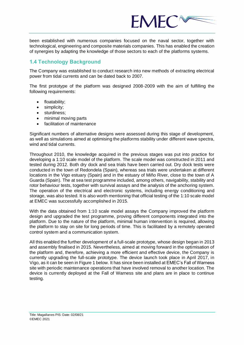
All this enabled the further development of a full-scale prototype, whose design began in 2013 and assembly finalised in 2015. Nevertheless, aimed at moving forward in the optimisation of
the platform and, therefore, achieving a more efficient and effective device, the Company is currently upgrading the full-scale prototype. The device launch took place in April 2017, in Vigo, as it can be seen in Figure 1 below. It has since been installed at EMEC’s Fall of Warness
site with periodic maintenance operations that have involved removal to another location. The device is currently deployed at the Fall of Warness site and plans are in place to continue
testing.

Title: Magallanes PIS: Date: 02/08/21
©EMEC 2021
Figure 1. Device launch in Vigo

Title: Magallanes PIS: Date: 02/08/21
©EMEC 2021
2 Device Description The full-scale prototype to be tested (at EMEC) can be broken down in the following blocks:
upper block, vertical block (or mast) and lower block (or nacelle).
Figure 2. Scheme of block distribution
Upper block
It is the visible block of the platform, as around a half of it is above the waterline. It is the block through which the platform is accessible for maintenance. It is divided into three main rooms:
one room is allocated to pumps and emergency power systems, whereas the other two rooms have been designed for accommodating the transformers, converters, switchgears and electrical panels, in addition to other parts of the electrical and electronic systems. Apart from these three main rooms, there are two inaccessible compartments at both ends of the block
which are part of the ballast system which employs fresh water treated, as well as several
tanks in the centre of the block for environmental acceptable lubricant supply and bilge water
Vertical block (mast)
Fixes the lower block to the upper block. It is a hollow space through which the communication and low-voltage cables connect the equipment housed in the lower block with the parts of the systems within the upper block. Rigid pipes for environmental acceptable lubricant supply and
draining, among others, are also installed in the vertical block.
Lower block
It is significantly smaller than the upper block and it is devoted to the mechanical system. The most relevant components placed in this block are the main shafts, ball bearings, gear boxes
and generators. As it had been indicated before, the platform is fitted with two counter-rotating

Title: Magallanes PIS: Date: 02/08/21
©EMEC 2021
rotors. As a result, all components of the mechanical system shall be in duplicate (one for
each rotor).
A scheme related to the mechanical system for one of the rotors is illustrated in Figure 3. The mechanical system for the other rotor is identical, but installed oppositely, in the other end of
the lower block.
Figure 3. Main components of the mechanical system
Out of the lower block but aligned with the main shaft is the hub with three blades, comprising
the rotor.
The following figure, Figure 4, outlines the indicative overall dimensions of the platform, in
metres.
Figure 4. Overall dimensions of the platform

Title: Magallanes PIS: Date: 02/08/21
©EMEC 2021
Dimensions have been rounded to the first decimal place.
Table 1 summarises the main specifications of the platform.
Table 1. Main specifications of the platform
Item Specification
Scale of the device Full-scale
Overall length 45 m
Extreme moulded breadth 6 m
Operational draught 23.4 m
Maximum output power Up to 2 MW
Number of rotors 2
Type of rotor Open-bladed rotor
Rotor diameter 19 m
Rotor depth More than 2.5 m clearance from sea surface (4.4 m approx.)
Blade/rotor design Blades with counter-rotating mechanism
Mooring system gravity-based anchors with four mooring lines attached (ca. 300 m, each)
Relative position of the device on the water’s surface
Not more than 300 m from the berth cable end
2.1 How it works
The platform is fixed to the seabed with four anchor points, two located at the bow of the platform and the other two at the stern. Once moored, tidal currents turn the blades of the two counter-rotating rotors, which are operational at the same time. The movement of those blades
produces the spinning of a shaft and, subsequently, by means of a generator, such mechanical energy is converted into electricity. A power transformer increases the voltage so as to reduce energy losses during power take off. Finally, the electricity generated by the platform is
transmitted first through an umbilical cable and then through EMEC’s subsea cables to
EMEC’s shore-based substation for onward transmission to the National Grid.
Concerning the umbilical cable, one of its ends will be inserted in the platform from the deck of the upper block (just above the electrical compartment). Then, the umbilical cable will be
fixed along the deck until it leaves the platform from one of the ends of the upper block (bow
or stern).
The diagram below, Figure 5, shows some of the components necessary for obtaining
electrical power from tidal currents, whereas in Figure 6 the scheme of the umbilical cable
entering the platform can be seen.

Title: Magallanes PIS: Date: 02/08/21
©EMEC 2021
Figure 5. Diagram of electrical power generation from tidal currents
Figure 6. Scheme of umbilical cable entering the platform
2.2 Mooring system
As it has been mentioned above, the floating platform is moored by bow and stern, fixed to
the seabed by means of four anchor points. Several anchor points, such as embedment anchors or gravity-based anchors have been assessed. Gravity-based anchors were the
chosen solution for the deployment at Fall of Warness.
In summary, the mooring system consists of 4 chain catenary legs, two north and two south, attached to one hull attachment points at the bow and stern. The mooring system holds the
ATIR platform in line with the current flow. The design is shown in Figure 7 below.
• Two legs are positioned along the centre-line, principally in line with the flow (approximately 10 degrees off).
• Two legs are offset from the centre-line by 45 degrees to the west. These lines assist
in reducing device yaw and easterly excursion.
Shaft
Gear box Generator
Transformer
Rotor blades
Subsea cable
Generator Gear boxShaft
Rotor blades
Tidal currents
Umbilical
cable
Drive Drive

Title: Magallanes PIS: Date: 02/08/21
©EMEC 2021
Figure 7. Proposed mooring system
Each mooring leg is identical, but only up to the gravity anchors themselves. The anchor sizes vary due to the statistically derived environmental loading and the larger environmental forces from the North. The elements comprising the mooring system together with their approximate
size are indicated below:
• Hull Attachment o A single padeye at the bow and stern, in which a single shackle is connected
and from which two mooring lines are attached.
• Upper catenary chain o 5m of 76mm chain o 40m of 80mm Bridon Superline Polyester o 5m of 76mm chain
• Excursion Limiter o 30m of 111mm chain or similar arranged in 4 lengths of 30m connected at each
end by a triplate.
• Ground Chain/Lower Catenary o 225m of 76mm chain
• Chain Clump Anchor (dry-weights) o The device is connected to the seabed using four chain clump weights with a
total capacity (wet weight) as follows:
▪ NW – 90 Te ▪ NE – 161 Te ▪ SE – 163 Te
▪ SW – 137 Te
For transporting and lowering chains and chain clump anchors, support vessels and vessels with deck crane may be used. Gravity-based anchors together with the mooring lines ensure that the position of the platform within the berth is maintained, and the survivability of the
device during its operation is guaranteed in rough wind conditions and waves.
A basic scheme of the mooring system to be used is illustrated in Figure 8 below.

Title: Magallanes PIS: Date: 02/08/21
©EMEC 2021
Figure 8. Scheme of mooring system
Anchor points will be settled in such a way that the platform will always stay within the limits of the berth, i.e. within approx. 300 m radius (included contingency) from the berth cable end. Nevertheless, once deployed the platform, exact coordinates of the anchor points will be
provided.

Title: Magallanes PIS: Date: 02/08/21
©EMEC 2021
2.2.1 Temporary mooring system
A temporary mooring site, either Deerness anchorage, Scapa Bay anchorage or Shapinsay
Sound test site, will be used for installing and removing the blades before device installation and after removal from the Fall of Warness site respectively. It is most likely that the Deerness anchorage site, or Scapa Bay anchorage site will be the most favourable due to
water depth requirements and limited tidal flow.
A multicat vessel will be used to tow the device from site to site as and when required. Moorings used at the temporary sites will only be installed for the duration of blade removal
works and will be removed shortly after the device has been towed back to Fall or Warness or southwards for maintenance. The temporary mooring locations were chosen due to the relatively benign conditions required for removing the blades which then allows the transportation of the device by towing to the chosen docks for maintenance. As the current
speeds are still quite considerable at the temporary mooring locations, significant maintenance activities are unable to be performed, hence transportation to a dry dock
elsewhere.
Details of Deerness anchorage, Scapa Bay anchorage and Shapinsay Sound sites can be
found in section 3.2.
The temporary mooring will use a single point mooring system as shown below in Figure 9,
due to the less extreme environmental conditions.
A Notice to Mariners will be issued before any works that require the removal of the device
from its moorings and transportation to another site.

Title: Magallanes PIS: Date: 02/08/21
©EMEC 2021
Figure 9. Single point mooring system schematic prior to device installation (Above), and during deployment (Below)
2.3 Materials used
Materials used in the construction of the device, together with the mooring system, are listed in the table below. Please note that around a 20% contingency has been added to the following deposit quantities, and it is expected that the final amounts will be less than those indicated in
the table below. If a licence is granted, a FEP5 form will be completed after installation to
confirm the quantities installed.

Title: Magallanes PIS: Date: 02/08/21
©EMEC 2021
Fall of Warness
Type of Deposit Nature of Deposit (P = Permanent, T = Temporary)
Deposit Quantity (tonnes, m3, etc.)
Steel/Iron P ≈ 800 tonnes
Timber - -
Plastic/Synthetic -
Composite P ≈ 10 tonnes
GRP - -
Concrete - -
Silt - -
Sand - -
Stone/Rock/Gravel - -
Concrete bags/mattresses
- -
Cable P ≈ 420 m
Other (please detail below):
Environmental acceptable lubricant (Biovesta-46, or similar),
fulfilling ISO 15380 requirements P ≈ 12 tonnes
Diesel oil
(for emergency power generator only) P ≈ 1 tonne
Shapinsay Sound
Type of Deposit Nature of Deposit (P = Permanent, T = Temporary)
Deposit Quantity (tonnes, m3, etc.)
Steel/Iron T ≈ 470 tonnes
Timber - -
Plastic/Synthetic - -
Composite T ≈ 10 tonnes
GRP - -
Concrete - -
Silt - -
Sand - -
Stone/Rock/Gravel - -
Concrete bags/mattresses
- -
Cable - -
Other (please detail below):
Environmental acceptable lubricant (Biovesta-46, or similar),
fulfilling ISO 15380 requirements T ≈ 12 tonnes
Diesel oil
(for emergency power generator only) T ≈ 1 tonne
Deerness Anchorage
Type of Deposit Nature of Deposit (P = Permanent, T = Temporary)
Deposit Quantity (tonnes, m3, etc.)

Title: Magallanes PIS: Date: 02/08/21
©EMEC 2021
Steel/Iron T ≈ 470 tonnes
Timber - -
Plastic/Synthetic - -
Composite T ≈ 10 tonnes
GRP - -
Concrete - -
Silt - -
Sand - -
Stone/Rock/Gravel - -
Concrete bags/mattresses
- -
Cable - -
Other (please detail below):
Environmental acceptable lubricant (Biovesta-46, or similar),
fulfilling ISO 15380 requirements T ≈ 12 tonnes
Diesel oil
(for emergency power generator only) T ≈ 1 tonne
Scapa Bay Anchorage
Type of Deposit Nature of Deposit (P = Permanent, T = Temporary)
Deposit Quantity (tonnes, m3, etc.)
Steel/Iron T ≈ 470 tonnes
Timber - -
Plastic/Synthetic - -
Composite T ≈ 10 tonnes
GRP - -
Concrete - -
Silt - -
Sand - -
Stone/Rock/Gravel - -
Concrete bags/mattresses
- -
Cable - -
Other (please detail below):
Environmental acceptable lubricant (Biovesta-46, or similar),
fulfilling ISO 15380 requirements T ≈ 12 tonnes
Diesel oil
(for emergency power generator only) T ≈ 1 tonne
Please note that all deposits (steel/iron, composite, etc.) referred to as “Temporary” are due to the fact that the platform is going to be temporarily moored at the Shapinsay Sound scale test site, Scapa Bay anchorage or Deerness anchorage, before it is finally towed and deployed
at Fall of Warness test site.

Title: Magallanes PIS: Date: 02/08/21
©EMEC 2021
3 Project Description 3.1 Location
The platform is deployed at the EMEC Fall of Warness test site, off the island of Eday, Orkney,
in the allocated berth. Nevertheless, in certain moments, the platform will make use of EMEC’s Shapinsay Sound test site, Scapa Bay anchorage or Deerness anchorage. The more benign conditions found in the temporary locations will facilitate the assembly and disassembly of the
rotor blades, as well as the undertaking of other maintenance works, if needed.
Figure 10. Chart showing the area of EMEC Fall of Warness test site. Magallanes Crown Estate lease outlined with solid
red line. Moorings shown in blue. Fall of Warness tidal test site Crown Estate lease shown as dashed red line
Title: Magallanes PIS: Date: 02/08/21
©EMEC 2021
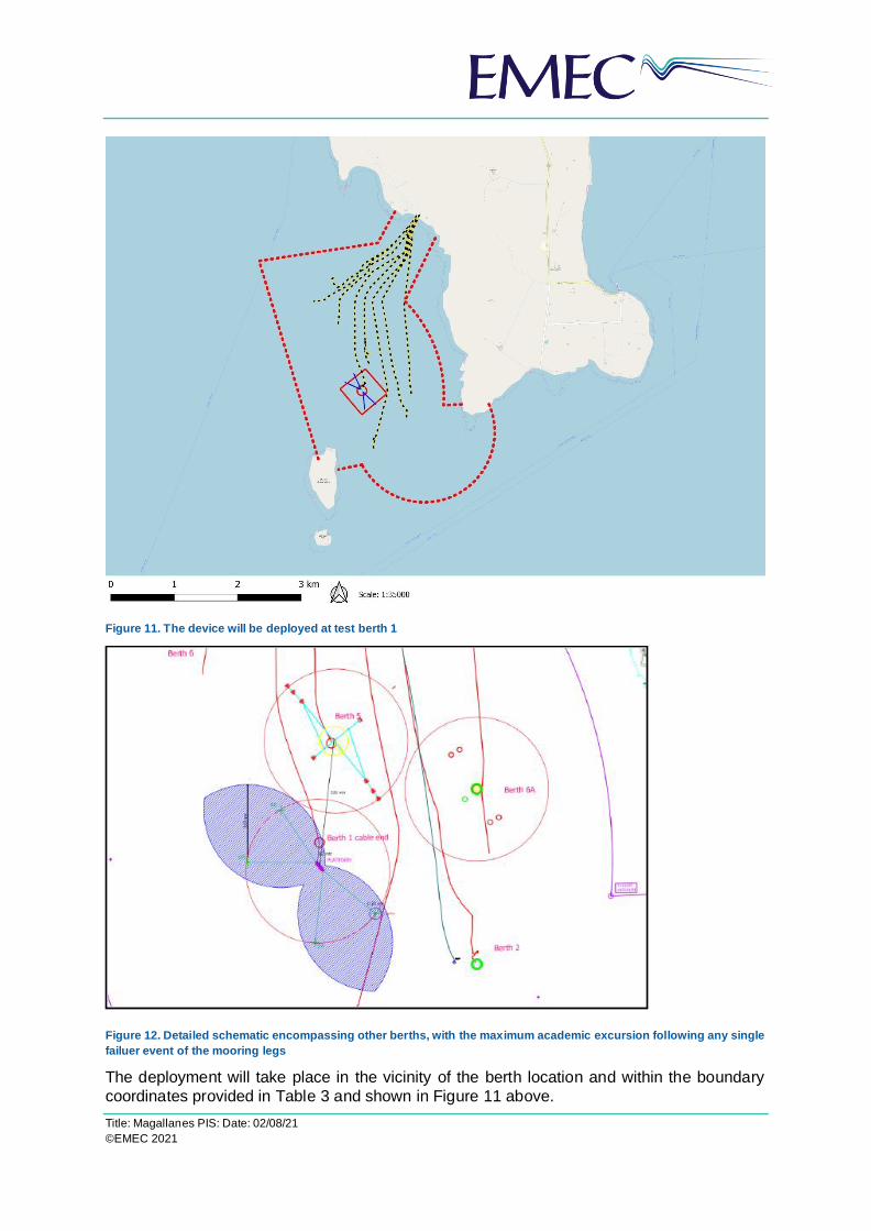
Figure 11. The device will be deployed at test berth 1
Figure 12. Detailed schematic encompassing other berths, with the maximum academic excursion following any single
failuer event of the mooring legs
The deployment will take place in the vicinity of the berth location and within the boundary
coordinates provided in Table 3 and shown in Figure 11 above.

Title: Magallanes PIS: Date: 02/08/21
©EMEC 2021
Table 2. Deployment location at EMEC's Fall of Warness test site
Test berth Latitude (WGS84) Longitude (WGS84)
Berth 1 59° 08.479’N 02° 49.080’W
Points along platform deployment boundary
59º 08.673’N
59º 08.463’N
59º 08.282’N
59º 08.503’N
02º 49.048’W
02º 48.693’W
02º 49.113’W
02º 49.471’W
3.2 Installation method
The platform is deployed at Fall of Warness berth 1, however if the device is removed for maintenance then it will be re-installed using the following method. The platform, without the blades, will be towed by a tug vessel from a safe harbour where repair works will take place, to Shapinsay sound tidal test site, Scapa Bay anchorage or Deerness anchorage. At present,
the details of the tug are not known, but it is expected such a vessel will have a length no
greater than 31m and draught up to 5m.
Figure 13. Map showing area of EMEC's scale tidal test site, Shapinsay Sound
Table 3. Attachment points at EMEC’s Shapinsay Sound test site
Attachment point Latitude (WGS84) Longitude (WGS84)
Anchor A 59º 00.200’N 02º 53.073’W
Anchor B 59º 00.165’N 02º 52.918’W

Title: Magallanes PIS: Date: 02/08/21
©EMEC 2021
Figure 14. Map showing area of device temporary deployment at Deerness Sound
Table 4. Boundary of lease area for temporary mooring at Deerness anchorage
Anchorage Latitude (WGS84) Longitude (WGS84)
Proposed temporary deployment boundary
58º 58.813’N
58º 58.564’N
58º 58.564’N
58º 58.813’N
02º 45.388’W
02º 45.388’W
02º 44.829’W
02º 44.829’W

Title: Magallanes PIS: Date: 02/08/21
©EMEC 2021
Figure 15. Map showing area of device temporary deployment at Scapa Bay anchorage
Table 5. Boundary of lease area for temporary mooring at Scapa Bay anchorage
Anchorage Latitude (WGS84) Longitude (WGS84)
Proposed temporary deployment boundary
58º 56.17’N
58º 56.17’N
58º 55.74’N
58º 55.74’N
03º 01.61’W
03º 00.70’W
03º 00.70’W
03º 01.61’W
3.2.1 Blades installation methodology
Once the platform is moored at either Shapinsay Sound, Scapa Bay or Deerness Sound, a
multicat workboat with a deck crane will load the blades from a port facility around Orkney and transport them to the temporary site of deployment. Depending on the deck area, one or more
blades may be transported at once.
After the vessel lies alongside the platform, by means of several slings and the deck crane, one blade is lifted and taken down until it is located below the water surface, below the upper block of the platform. Once there, with the help of a cable/sling guidance system, the blade is attached to the underside of the upper block hull. The guidance system also ensures the blade
is positioned vertically (with the top of the blade upwards and the root, downwards), just above
the nacelle hub.
Provided that the blade is vertical and above the nacelle hub, the blade is then lowered using
tackles or similar equipment, until the blade root fits in the nacelle hub. Afterwards, by means

Title: Magallanes PIS: Date: 02/08/21
©EMEC 2021
of nuts and bolts the blade is fitted to the nacelle hub. Finally, the guidance system is
disengaged from the blade installed, so that it can be used for the assembly of another blade.
Once installed the first blade, the methodology for assembling the remaining five blades (each
rotor consists of three blades) would be similar.
3.2.2 Fall of Warness mooring works
In parallel, the mooring system at the selected berth at Fall of Warness will be prepared, as described in section 2.2 above. Aimed at knowing the conditions of the seabed prior to the deployment of the platform, a pre-installed seabed survey will be undertaken. This information
will be useful for assessing, after the decommissioning of the platform, whether the site has
been left in the same condition as it was before the installation.
Once all components and subsystems are fully assembled and the mooring system installed, the platform will be towed by a tug vessel from Shapinsay Sound test site, Scapa Bay
anchorage or Deerness anchorage to Fall of Warness. During the towing, the blades will be blocked in order to avoid their rotation. By means of four chain catenary legs, two by bow and two by stern, the platform will be attached to the anchor points, as it had been indicated in
section 2.2 above, in order to be held in place.
Finally, the platform will be connected to EMEC’s subsea cable, connecting the test berth to the shore-based substation. For that purpose, firstly, EMEC’s subsea cable end will be lifted by deck crane from the berth seabed to the deck of one of the vessels participating in the
installation of the platform. Afterwards, EMEC’s cable will be spliced to an umbilical cable, expected to be less than 400m length, connected to the switchgear housed in the platform,
and it will be laid back to the seabed.
The company will work closely with local companies experienced in marine operations, with knowledge of the test site and available equipment and vessels to develop detailed procedures for the various activities related to the installation of the platform. It is not known yet the vessels
which will be involved in the installation of the platform at the test site but, due to the characteristics and dimensions of the device, typical workboats or multicat workboats such as MV C-Odyssey, MV C-Salvor, MV C-Chariot, or similar, (with lengths no greater than 28m and draught up to 4m) rather than large installation or heavy lift vessels will be used. In addition, it
may be necessary to utilise support vessels (such as MV Ocean Explorer, or similar) for some
tasks during the installation of the platform.
3.3 Operations and Maintenance Works
Due to the nature of the platform, minimal human intervention may be required, allowing the platform to stay on site for long periods of time. This is facilitated by the remotely operated
control system and the communication system.
However, during the period the platform will be delayed, there will be surveillance and maintenance on site. Visits will take place at regular intervals, at least once per month,
although during the first month of platform operation, visits may be more frequent.
The platform has been designed in such a way that there is enough inner space for having an accessible machine room, both in the upper block and the lower block. In addition, the lower block is accessible from the upper block through the vertical block. As a result, repairs can be done offshore with no need to take the platform to a shipyard for maintenance. It should be

Title: Magallanes PIS: Date: 02/08/21
©EMEC 2021
possible to carry out in situ all maintenance activities, dependant on weather and tidal
conditions.
In general, the vessels to be used during maintenance works are support vessels (such as MV Ocean Explorer, or similar), although it is not discarded the use of typical workboats or
multicat workboats in the event of maintenance tasks which require more extensive equipment (for dive support, for example, or major corrective actions). In this sense, it may be necessary
that those workboats will be assisted by support vessels.
3.4 Decommissioning / removal method
The decommissioning method will be quite like the installation method but conducted
conversely.
As a first step, the platform will be disconnected from the EMEC subsea cable. In order to
undertake such disconnection, EMEC’s subsea cable end will be lifted back by a deck crane from the seabed to the deck of one of the vessels, umbilical cable will then be disconnected from the EMEC cable mand, finally, the EMEC cable will be laid back to the seabed in the
condition in which it was first taken over.
Afterwards, the platform will be detached from the mooring lines with the help of a multicat workboat and towed by a tug vessel from Fall of Warness test site to one of the temporary sites, where it will be temporarily moored for no more than two weeks. At the temporary
mooring the blades will be disassembled from the platform by a dive team supported by a multicat workboat with a deck crane. The methodology for detaching the blades from the
nacelle hub will be similar to that described in section 3.2 above but undertaken in reverse.
If required, a dive team may help in the recovery of the mooring system by the crane of one of the vessels participating in the decommissioning of the platform. All remaining components which constitute the platform mooring system at the berth might be dismantled, on the
condition that such removal doesn’t entail further disturbance or impact on the environment.
Local companies with experience in marine operations (most probable the company that would have been involved with the installation of the platform) will participate in the platform decommissioning. In this sense, it is expected that conventional vessels like those employed
during platform installation (workboat, multicat workboat, support vessel) will be used for the
decommissioning.
A decommissioning programme will be produced in support of the marine licence application,
which will outline the decommissioning procedure and associated schedules.
3.5 Anticipated vessel traffic to site
Due to the installation, surveillance/maintenance and decommissioning of the platform, vessel
traffic is expected at Fall of Warness site and its surroundings. Vessels expected to be used are workboats, multicat workboats and support vessels. Listed below are the most significant
activities together with the anticipated frequency of vessel movements.
Table 6. Operational activities and anticipated frequency of vessel movements
Activity Anticipated frequency of vessel
movements
Platform installation

Title: Magallanes PIS: Date: 02/08/21
©EMEC 2021
Preparation and installation of moorings at Fall of Warness
5-10 day trips
Assembly of blades at Deerness anchorage or Scapa Bay anchorage
8-10 day trips
Towing the platform from Deerness anchorage or Scapa Bay anchorage to Fall of Warness
1 day preparation
1 day towing operation (2 x vessels)
Installation of the platform (including attachment to the mooring and subsea cable connection)
8-10 day trips (possibly over 2 x neap periods)
Surveillance/maintenance
Surveillance on site Visits at regular intervals. 2 trips per month (1 day trip). During the first month of platform operation, visits might be more frequent.
Maintenance on site Visits at regular intervals. 1 trip per month (1 day trip). During the first month of platform operation, visits might be more frequent.
Towing the platform for maintenance in calmer waters
2-3 day trips
Redeployment of platform at Fall of Warness after maintenance in calmer waters
4-6 day trips
Platform decommissioning
Decommissioning of the platform (including unmooring and subsea cable disconnection)
8-10 day trips (possibly over 2 x neap periods)
Towing the platform from Fall of Warness to Deerness Anchorage or Scapa Bay anchorage
1 day trip
Disassembly of blades 6-8 day trips
Decommissioning of moorings at Fall of Warness 5-10 day trips
It has been considered that all schedules might vary since, among other factors, they are subject to suitable environmental and tidal conditions and, therefore, adverse weather may increase the forecasted duration of activities. Furthermore, it should also be remarked that due to unplanned maintenance because of exertional circumstances, additional trips might be
required. Notice to mariners will be issued prior to understanding works onsite, specifying the
type of works to be carried out and its duration, as well as the vessel(s) involved.
3.6 Device monitoring systems
The platform together with its subsystems is going to be monitored continuously in order to ensure that they operate properly and in order to be able to respond rapidly in case of an
emergency. The most relevant device monitoring systems are outlined below, see Table 6.
Table 7. Platform monitoring systems
System Description
General monitoring systems

Title: Magallanes PIS: Date: 02/08/21
©EMEC 2021
General position system (GPS)
It records time and date continuously, provides the exact
position of the platform at all times and transmits the
information to shore.
The platform is expected to move on the sea surface
within an area previously assigned (based on ebb and flow, depth, length of mooring lines, etc.). In the event that the platform is not held in place, but out of the pre-established range, this may mean that there has been a
failure in one of the mooring lines. In such case, GPS will warn without delay about the abnormal position of the platform. This will help to provide a rapid response (with
vessels, dive team, etc.) so as to return the platform to a
safe and agreed location.
Inertial measurement unit
(IMU)
Used for monitoring platform stability in terms of pitch, roll
and yaw degrees.
Weather station
It records outside temperature, atmospheric pressure, wind speed and wind direction, among others. It helps to anticipate rough weather conditions that may impact on
platform behaviour.
Insulation monitoring device
Employed in order to monitor the insulation resistance of unearthed main circuits and to detect early deterioration
in the insulation.
Current meter Instrument for providing with relative water velocity data and
measurement of local flow conditions in real time.
Specific monitoring systems
Variable pitch system It allows the blades configuration and pitch to change
according to the current.
Shaft positioning system
It assures the proper orientation of the rotor blade shaft, so that loads are balanced. It is also intended for
facilitating blade assembly and disassembly.
Emergency response systems
Fire detection system
Set of devices aimed at detecting fire or smoke in the
platform and raising the alarm so as to respond as soon
as possible and minimise the damages caused.
Bilge pumping system
Provided that unwanted water is present in the platform, and in order to prevent flooding of it, the system is
arranged to drain any watertight compartment.
Uninterruptible power supply
system (UPS)
In the event of failure in the main power source, this system will provide with emergency power to electrical
devices so that they can keep running temporarily.
Emergency braking system
If an important fault takes place and such fault entails a risk for the integrity of the platform, emergency braking
system comes into operation in order to stop mechanical
system and, as a result, block rotor blade rotation.

Title: Magallanes PIS: Date: 02/08/21
©EMEC 2021
Apart from the aforementioned monitoring and response systems, other variables such as
temperature, humidity, pressure, voltage, power, etc. will be monitored within the platform. Furthermore, the main components such as generators, converters and gear boxes, among others, will also be monitored in order to ensure they work suitably. Two cameras might also
be installed at the deck of the platform, one at the bow and one at the deck, for surveillance
purposes.
Owing to the nature of the platform, which is conceived for minimising required human intervention, a remotely operated system is developed in order to display and store within the
platform the most relevant parameters. Communication with the platform is established thought he umbilical cable at EMEC’s subsea cable. Nevertheless, in the event of loss communication, a satellite or radio communication system, which will behave as a redundant
system until required, can be utilised. Both communication systems allow the transmission
and operation of the control system variables remotely.
3.7 Third Party Verification (TPV)
With the aim of undertaking the Third Party Verification it is proposed to engage the services of Orcades Marine Maritime Consultants Ltd, which provides Marine Project Management, Specialist Marine Risk Management, Innovative and Practical Consultancy Advice, Third Party Verification and Marine Warranty Survey, Independent Auditing and Assessment to the
Shipping and Port Industry, the Marine Renewable Energy Sector, and the Offshore Oil and Gas Industry, accredited to ISO 9001 and OHSAS 18001 for the provision of those services
to the industry.
Orcades Marine Maritime Consultants has a wide experience in third party verification and marine warranty in the marine renewable sector. Among others, they have been involved in the following works: TPV for a tidal floating system for marine licensing purposes for the
installation in Orkney, independent opinion as to the suitability of a grounding berth for securing a vessel safely alongside, or Marine and safety advisors for the installation of a tidal turbine in Singapore. Some of their clients in the past have been Tocardo, Sustainable Marine
Energy, Aquatera or Andritz Hammerfest.
For all the above, the Company believes that Orcades Marine Maritime Consultants is appropriate to conduct the verification of the platform and its moorings. Such verification will certify the integrity of the structural design of the platform and its moorings for the conditions
expected at test berth 1, Fall of Warness.

Title: Magallanes PIS: Date: 02/08/21
©EMEC 2021
4 Project Schedule
The device is currently deployed at berth 1, Fall of Warness. This applications purpose is to
extend deployment. The device may be removed from site during the lifetime of this licence for maintenance and repairs. If the device is removed, a NtM will be issued, and Marine
Scotland and all consultees will be notified.