machine types
DESCRIPTION
equipment machine typesTRANSCRIPT

Soil Dynamics Prof. Deepankar Choudhury
Department of Civil Engineering Indian Institute of Technology, Bombay
Module - 5
Machine Foundations Lecture - 25
Types of Machine Foundations, Methods of Analysis, Design of Machine Foundations as per IS:2974 (Part -1)-1969
Let us start our today’s lecture on soil dynamics. Now, we will start our module five next
module, which is machine foundations. A classification of different types of machine
foundations; if we put all different types of machine foundations whatever are used
worldwide, it can be categorized in major three categories machine foundations.
(Refer Slide Time: 00:54)
Those are for three different categories of machines, the first category is reciprocating
type machine. Second category of machine is impact type of machine and third category
of machine is rotating type of machine. So, these are three major categories of machines
for which the foundations has to be designed. Now, within each of these let us see what
are the different characteristics and examples what we can find.

(Refer Slide Time: 01:27)
For reciprocating machine, the first category what are the features or characteristics?
These machines produce periodic unbalanced force example of such type of machine
compressor, reciprocating engine etcetera. What are the typical operating frequencies
ranges of operating frequencies for reciprocating machine? They are usually less than
600 rpm. Rpm you know revolutions per minute. So in our SI unit when we are doing
calculations we need to convert this rpm to cycles per second. For analysis of such
machine foundation generally the unbalanced force can be considered as sinusoidal
because the first characteristics what we have mentioned, they generally produce
periodic unbalanced force. So, that is why they can be approximated as sinusoidal
loading is acting for this kind of machine, it is considered.

(Refer Slide Time: 02:44)
Coming to second category of machine, that is impact type of machine. Of course, they
produce impact loads as the name suggest. In this category example of impact type of
machine is forge hammer and what is the typical range of operating frequency for these
machines typical range is about 60 to 150 blows per minute. That is the typical operating
frequency for impact type of machine. As we know about the characteristics of impact
load dynamic loads attain peak value in a very short time and then die out. That is the
characteristics of impact load that we already know. So, obviously the same thing same
type of load impact load will act on these type of machines, impact type of machines as
the name suggest.
(Refer Slide Time: 03:48)
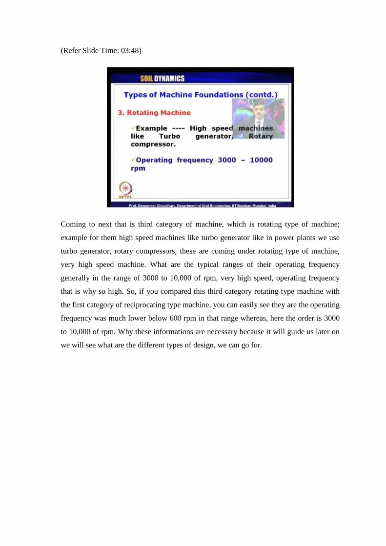
Coming to next that is third category of machine, which is rotating type of machine;
example for them high speed machines like turbo generator like in power plants we use
turbo generator, rotary compressors, these are coming under rotating type of machine,
very high speed machine. What are the typical ranges of their operating frequency
generally in the range of 3000 to 10,000 of rpm, very high speed, operating frequency
that is why so high. So, if you compared this third category rotating type machine with
the first category of reciprocating type machine, you can easily see they are the operating
frequency was much lower below 600 rpm in that range whereas, here the order is 3000
to 10,000 of rpm. Why these informations are necessary because it will guide us later on
we will see what are the different types of design, we can go for.

(Refer Slide Time: 04:58)
What are the basic design criteria for machine foundations? First one of course, these
foundations has to be designed for the static load. These foundations should be well
design to take care of the static loads coming on the foundation. So, what are the checks
we do for static loading? We have to do the same thing here that is no shear or bearing
capacity failure should occur. That means we have to check the bearing capacity of the
foundation and have to satisfy, the factor of safety with respect to bearing capacity etc.
Whatever we provide in static design of any kind of footing shallow footing of course,
here we are taking about mostly shallow footing, we have to check that criteria.
The second criteria we check about no excessive settlement, that is amount of settlement
also we need to calculate under static load and that has to be compared with different
codal guidelines. As we know for isolated footing as per IS code about 50 millimeter.
That is what is the vertical settlement. So, like that raft it is 75 millimeter like that
different ranges are already given as per different design code, that has to be checked
whether that criteria is satisfy or not. When you are going to design any foundation
irrespective of whether it is machine foundation or not. Now, what additional checks we
need to do for the design?
That is for dynamic loads of course, these are additional loads coming for these
foundations, which are supporting the machines. So, in that check for dynamic load, we
have to check for three criteria. These are the three major points. What are those? The
first one is no resonance condition of course, the under the dynamic load your foundation
should not resonate. Otherwise what will happen, it will have excessive settlement or
excessive deflection because we have seen at resonance. the DMF dynamic
magnification factor compared to that is dynamic displacement compared to the static
displacement is tremendously high. So, that condition has to be avoided so, no resonance
condition.
To do that, what is the basic criteria we should follow that operating frequency of the
machine must not match with the natural frequency of the machine plus foundation
system. So, when we are talking about the system when we are designing the foundation
we are not only talking about the foundation itself we are talking about foundation plus
machine together because the entire assembly is going to vibrate together So, remember
when you are calculating the natural frequency. The natural frequency has to be
calculated for the entire system, not for the foundation only. So, remember this this is an
important point because consideration of your mass of the, which mass you should take
the foundation mass or the foundation mass plus the machine mass, that is what you
should take.
The second one to calculate the natural frequency to avoid the resonance. So, they should
be far away from each other. Second important criteria for design is that dynamic
displacement amplitude, the amplitude of displacement under dynamic condition what
we are obtaining that amplitude must not exceed the permissible limit. That permissible
limit again will be given by different codal provisions, that we will discuss for our IS
code, what is the codal provision? So, we must not exceed the dynamic amplitude should
not exceed that permissible limit given to us, it is in addition to this static settlement.
Remember this here we are talking about only the dynamic component of the amplitude.
What is the third criteria? Third criteria is based on the vibration of the machine and
foundation system together, it must not be annoying to the person working in the
environment and it should not damage the adjacent structures. So, when you are
designing any machine foundation, what you should not only provide a strong foundation
which can take care of the dynamic load by assuring that it is safe against bearing
capacity failure, excessive settlement under static load condition as well as it is safe
against no resonance criteria and this amplitude dynamic amplitude is less than
permissible limit.
Even then there can be a chance that, the vibration created by your machine and
foundation assembly be dangerous for adjacent structures or it can be annoying to the
persons, who are staying in surrounding area. So, that should not be there. So, this is a
kind of qualitative assessment. All other four criteria, first two for static and first two of
the dynamic. These four are quantitative criteria, when you are going to design the
foundation you can check quantitatively these parameters providing factor of safety and
things like that you can design a safe foundation for the machines. However, this last
criteria is based on a qualitative issue. So, how to measure that? This qualitative
assessment has been provided by Richart.
(Refer Slide Time: 11:27)
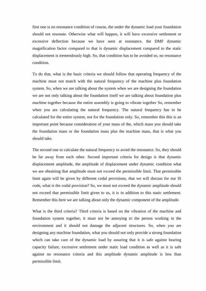
That I will show you soon. In some of the slide later on let us discuss now, different
methods of analysis for machine foundations. There are basically three methods of
analysis for design of machine foundation. The first method is called MSD model that is
nothing but mass-spring-dashpot model. The second method is called EHS theory, EHS
theory means it comes from this elastic half space, EHS elastic half space model it is
based on linear theory of elasticity, that is another method of analysis for designing
machine foundation. And the third method is called Tschebotarioff’s reduced natural
frequency method.
The method proposed finally, in 1953 by this scientist Tschebotarioff. What about this
method? This is a kind of semi-empirical method that is Tschebotarioff had proposed for

different types of soil based on different frequency, exciting frequency, what at the
reduced natural frequency of the machine plus foundation system. So, it is a semi-
empirical method proposed through design charts by this Tschebotarioff’s Originally this
method was developed also for earth retaining structures. So, it can also be used for any
type earth retaining structure analysis or design. Now, we will go through each of this
theory and we will see that how one machine foundation can be designed using all these
three different theories. Now, typical types of machine foundations which are generally
designed, those are block type, box or caisson type and wall or frame type.
(Refer Slide Time: 13:49)
So, these are three typical major types of machine foundations, which are generally
designed. Block type machine foundation, box or caisson type machine foundation, wall
or frame type machine foundation.

(Refer Slide Time: 14:13)
Block type machine foundation will look like this, as the name suggest it is a solid block
made of concrete mostly. So, this pedestal machine motor like that, it will be positioned
on the top of the block. So, this is the most common type of machine foundation used
worldwide. Block type of machine foundations, just a concrete block huge mass of area
and depth.
(Refer Slide Time: 14:49)
Second type of machine foundation is box or caisson type. It depends when you will go
for box or caisson type to save some material of your concrete because in the block type

of foundation sometimes in the design procedure you may find that if you provide a
block type of foundation, it requires a huge size means area as well as height of the
foundation. In that case sometimes it may lead to an uneconomic design, in that case we
can check if we can provide a box or caisson type of foundation where this will be a
hollow portion and these are concrete area and on top of it, this machines will be
positioned.
(Refer Slide Time: 15:39)
And the third category of machine foundation is wall or frame type of machine
foundation. So, it is like as we go for the structural frames, in the same fashion we have a
footing then walls and columns and then a beam and slab on top of which we position the
machine. So, that is nothing but called wall or frame type of machine foundation.
Generally for the third category of machines, where they are subjected to very high
operating frequency like turbo generator etc many a times we have to go for probably
this wall or frame type of foundations. Whereas, for reciprocating machines etc where
operating frequency is pretty small, block type of foundation will be more commonly
used or economically valid.

(Refer Slide Time: 16:45)
Now, let us discuss what are the different types of motion that machine foundations can
be subjected to. In other words how many degrees of freedom one machine foundation
can be subjected to. Of course, it is a three dimensional body so, it can have 6 degrees of
freedom, that is three translational and three rotational, total six degrees of freedom.
Now, what are those named? What are those vibrations called for machine foundation?
So, this is a block type of machine foundation is shown in this picture, we have three
orthogonal axis system, this is x-axis, this is y-axis and this one is z-axis.
If the foundation is vibrating in this direction. that is called vertical vibration for machine
foundation. In that case the dynamic load is this P z, that is vertically applied dynamic
load. That is causing the vertical vibration to the machine. Next one is look at this, when
it is vibrating about this direction that is in x direction it is vibrating, under the action of
this dynamic load P x, then it is called lateral or it is also called sliding mode of vibration
lateral or sliding mode of vibration.
Now, when the machine foundation vibrates in this direction, that is when it is subjected
to the dynamic load of P y like this, then the name of the vibration is longitudinal
vibration or again it can be called as sliding vibration. Remember here sliding occurs in x
direction, here sliding occurs in y direction. That is the only difference, otherwise both of
them can be called as horizontal vibration or sliding vibration or lateral or longitudinal
vibration. So, these are the common terminologies, you should remember they are called

horizontal vibration or sliding vibration or lateral or longitudinal vibration and this is one
is vertical vibration.
Now, these three are the translational vibration. Now, let us see the three rotational
vibrations. When your machine foundation is subjected to a dynamic load like this that is
subjected to a moment M x dynamically applied it can rotate about x-axis that mode of
vibration is called pitching mode of vibration, it is called pitching mode of vibration.
When the block foundation is subjected to a dynamic load, M y like this, then the
rotational vibration of the block about y-axis is called rocking mode of vibration and
when the block is subjected to a dynamic load like this M z in that case it is called
yawing mode of vibration. So, three rotational modes of vibration for any machine
foundations are pitching rocking and yawing so, total six modes of degrees of freedom or
six modes of vibrations for any machine foundation are vertical vibration two horizontal
vibrations pitching vibration rocking vibration and yawing vibrations.
Now, depending on your applied load either any one of them can occur for your machine
foundation system or a combination of them can occur for a machine foundation system.
So, we have to check that when we are going to design a machine foundation? What are
types of dynamic loads acting on the system and what are the possible modes of
vibration based on that your analysis will lead you to whether it is individual rocking
pitching or vertical or horizontal mode of vibration or a combined effect of sliding and
rocking something like that. So, that we have to decide based on the given load
conditions.
(Refer Slide Time: 22:06)
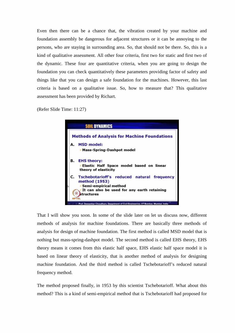
Now, coming to the Indian standard design code provisions. What it says design of
machine foundation as per our Indian standard code IS 2974 part one of 1969. It says that
machine foundation has to be designed by checking three criteria's. One is called
dimensional criteria, another one is called vibration criteria and the third one is called
displacement criteria. So, these are the three major criteria, which needs to be checked
when we are going to design a machine foundation as per our Indian standard design
code 2974. What are these criteria? Let us discuss them in detail now.
(Refer Slide Time: 23:02)

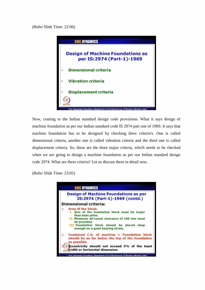
The first one dimensional criteria. What it says in dimensional criteria, we have to find
out or check the area of the block. We are going to provide block means block type of
foundation assuming that we are providing a block type of foundation. What are the
criteria given that size of the foundation block must be larger than the base plate of the
machine, which is quite well understood and quite obvious actually. Suppose, we have a
machine for which we have a base plate like this. This is the plate provided by the
manufacturer to us on top of it the machine will be kept and finally, this plate has to be
placed on top of our block type of foundation.
(Refer Slide Time: 23:49)
What it says through these points? We will bolt or connect the base plate mostly the steel
type of plate to the concrete block type of foundation and for that purpose, what we
need? The area of the block, which we are providing should be bigger than that of the
base plate otherwise we cannot fix them of course. So, let us look, it look at here again in
the slide. The second criteria says minimum all-around clearance of 150 millimeter must
be provided. So, this is the second guideline it says as per our IS code, what it says? That
this clearance has to be 150 millimeter all around. 150 millimeter minimum. This is the
minimum clearance, we have to provide all around the base plate and foundation edges.
Let us look at the slide once again. Third criteria says that foundation block should be
placed deep enough on a good bearing strata. Of course, we should place it in a good
soil, stiff soil which can take that vibration of the machine plus foundation system. The

second criteria says that combined C G combined center of gravity of the machine plus
foundation block, that is we can easily calculate by knowing total size and height of the
foundation after designing it, we know where the C G of the foundation lies and also for
the machine weight we know where the C G etc lies for the machine. Now, you combine
them this combined C G of the machine plus foundation block should be as far below the
top of the foundation as possible. That is it should be as close as to the base of the
machine plus foundation system.
Why because if there is some eccentricity arising out of your operation of the machine in
future or if some additional loads are allowed later on on the foundation, it should not
create the rotational vibrations in future. So, that is why if you keep the C G of the entire
system as low as possible, obviously your generated moments etc load coming on the
foundation will be much lesser that is why this criteria is mentioned. And the third
criteria for the selection of the area, it says eccentricity should not exceed 5 percent of
the least width or horizontal dimension. That is whatever is the least or smallest width or
smallest horizontal dimension of the block foundation you are designing, 5 percent of
that can be the maximum eccentricity, which can be allowed for your loads etc which is
applied on the foundation.
(Refer Slide Time: 28:06)
Now, let us go to the next criteria which is vibration criteria. The vibration criteria it says
it is expected to have a foundation which is having natural frequency, either much higher

or much lower than the operating frequency of the machine. Which is well understood to
avoid the resonance criteria, that no resonance condition the first condition of basic
criteria for design of machine foundation. So, that is why the natural frequency of the
machine plus foundation system should be much higher or much lower than the
operating frequency of the machine. Now, there are two cases mentioned. One is called
under tuned another is called over tuned. What are these? Let me explain you.
(Refer Slide Time: 29:06)
If we plot typically the frequency in x-axis and here the displacement so, typical
variation will be something like this. Now, resonance occurs for this frequency. Now, if
you keep your operating frequency of the machine far away from this point, either here
or here it will be safe. That is, if this is denoting your now, the applied frequency in that
case, it has to be far away from this resonance condition to have much lower
displacement. So, easily you have seen we can have either of the very high value than
natural frequency or very low value than the natural frequency of the machine plus
foundation system, to take care of this no resonance criteria.
What are the cases are proposed values typical ranges under tuned means this omega is
operating frequency and omega n is natural frequency of the system. If the ratio of
operating frequency to the natural frequency, is less than or equals to 0.5 that has to be
used for important machines and for less important machine, we can go up to 0.6 also.
So, in that case what is happening your natural frequency of the system is much higher

than the operating frequency. So, operating frequency is much lower. So, in the picture
what I have drawn here let us look here, this case is called under tuned. That is when we
are putting our operating frequency, much lower than the natural frequency and the other
case it is called over tuned.
So, what is over tuned? In that case operating frequency is much higher than the natural
frequency. So, in the slide also it is shown. Let us look at the slide. Over tuned this is
operating frequency, this is natural frequency. Ratio of them should be greater than or
equals to 2 for important machines and it can be greater than equals to 1.5 for less
important machine. Remember this sign as quite obvious from the understanding here it
should be less than or equals to whereas here it should be greater than or equals to, to
keep them far away from each other. Now, which one has to be chosen? Can you think
about it which condition of this under tuned or over tuned you should select as a
designer, when you are going to design a machine foundation.
It depends on the operating frequency or the type of machine for which you are going to
design the foundation. For example, if we are going to design the turbo generator
machine for that if we are going to design the foundation for which operating frequency
is very very high, in the order of 3000 to 10,000 rpm. In that case which condition you
will prefer under tuned or over tuned? It should be over tuned because if you want to
design an under tuned type of foundation for a machine like turbo generators you will
end up with very very high value of omega n because already omega is pretty high
omega n will be excessively high.
What does it mean? omega n excessively high means mass of the foundation will come
negligible. This k has to be excessively high because omega n is nothing but root over k
by M. In that case you will find some absurd result, sometimes your result after doing all
calculations you will get negative value of mass is required or no mass of the foundation
is required, but it is not the case.
So, your given value or input value of operating frequency decides whether you should
go for over tuned case or under tuned case. So, for that you have to go for over tuned
design, you do not have any other choice. Whereas let us look at the other type that is the
first category of machine, reciprocating type. Where typically the ranges of operating
frequency are below 600 rpm pretty low. In that case which type of design you should go

for? Of course, under tuned because this omega value is pretty low. So, you can go up to
a high value of omega n in that case if you try to do a over tuned design. Let us see what
will happen in that case omega is pretty low, omega n to maintain this factor these are
nothing but kind of factor of safety right we can say these are factor of safety against
resonance condition.
So, to maintain this values your omega n has to be again much much lower. What does it
mean? Omega n much lower means, mass of the foundation system will be very very
high. Means unnecessarily you are going into an uneconomic design so, in that case you
are able to design actually not like the previous case that you will get a absurd result.
Here you will get some possible dimensions of your foundations, but it will be an
uneconomic design. So, you have to check probably for some of the intermediate
operating frequencies.
Suppose, in the range of say 1000 rpm or even in the range of 600 rpm it is always better
to check your design for both over tuned and under tuned. Then you will get a, an idea
what are the dimensions of your footing required by considering whether under tuned or
over tuned. Then you do the cost analysis and provide or suggest accordingly that is both
safety and economy is maintained. Now, let us see the third.
(Refer Slide Time: 37:01)
Criteria as per the IS code, that is displacement criteria. What it says? That permissible
displacement remember, this displacement means only the dynamic displacement we are

talking about amplitude of displacement to be specific we are talking about only the
amplitude of dynamic displacement, that permissible value for machine foundation
system is, it should be less than or equals to 0.2 millimeter very very low. So, dynamic
displacement range it should not exceed 0.2 mm. If it is exceeding, then you have
redesign your foundation. The other criteria that is permissible displacement criteria
from qualitative assessment.
As I was talking earlier the third criteria for dynamic loading that is it should not be
annoying to the surrounding people or it should not be damaging to the adjacent
structures to maintain that the permissible displacement should be checked using
Richart’s chart. So, that it should not become annoying to the workers or adjacent
structures like that. So, Richart’s chart is worldwide it is used because this chart only
provides us that qualitative assessment. That needs to be checked when you are doing
any design of machine foundation, IS code also suggests that. Let us look at the Richart’s
chart now.
(Refer Slide Time: 38:51)
This is Richart’s chart. You can note down this Richart was proposed by the scientist
Richart in 1962 and this chart is valid for only vertical mode of vibration please note it
down. This chart how was developed? It was developed from several experimental
results, that is what if you look at the top of the chart it is given that from Reiher and
Meister in 1931 steady state vibration, from Rousch 1943 steady state vibrations, from

Crondel 1949 due to blasting. So, after assembling all these affects Richart, what he did?
He divided the chart into different zone. What is y-axis of the chart that is displacement
amplitude and of course, this is dynamic displacement.
It is what the to mention it is amplitude only. So, that is why they have shown here this is
the maximum value. This a and unit also you should record it is in inch unit, Richart
chart is in FPS unit So, whenever you are doing your design in SI unit you need to
convert it, that is after getting calculated the dynamic displacement amplitude, you need
to convert it to inch unit, to read your Richart chart. What is x-axis? x-axis gives
frequency, it means operating frequency of the machine. In the unit CPM. CPM means
cycles per minute that is same as revolutions per minute nothing but and remember this
x-axis is in logarithmic scale also y-axis is in logarithmic scale. So, that is why this is
100, this is 1000, this is 10,000.
As I said, turbo generators etcetera will be in this range of operating frequency whereas,
your reciprocating machines will be in this range of operating frequency. Now, based on
your machine for which you are designing the foundation and from your calculated
displacement amplitude from the analysis using any of the model, you go to this chart
then your point will come to any of this zone. So, that will guide you whether it is good
or not? So, what Richart said this line this boundary gives not noticeable to person. So,
suppose if your point after calculations it comes somewhere say operating frequency was
500 rpm and maximum displacement amplitude in inch is 0.0002 inch so the point will
come here that means your designed foundation will not create any problem, to any
people or any adjacent structure because the vibrations are not noticeable to persons.
That is the most safest zone.
Next zone is this one barely noticeable to persons. If your point design point comes here
it will be hardly noticeable to the person. Next zone is easily noticeable to person, this
zone is troublesome to person, this zone is severe to persons, this is the final limit for
machines and machine foundation. So, beyond this we should never go because then
danger to the structures or caution to the structures come into play that is adjust structure
will be affected. So, it is always preferred to be up to this maximum of easily noticeable
to person zone but preferably if it is within these two zone. Then you have designed your
machine foundation in the best possible way so, this is the qualitative assessment one
must do for machine foundation design.

But you can see for very high value of rpm it is very very difficult to come to this zone.
So, that is why I said you can go up to this zone also for turbo generator, that is why of
course, we know that power plants etc or not in the close vicinity of any residential area
or things like that or hospital or schools and more so far their turbo generators etc
because of this result. Now, this chart what I have shown you. This is valid only for
vertical mode of vibration. what about other modes of vibration? One more chart is
available.
(Refer Slide Time: 44:23)
Let us look here. Yes this chart this chart was given by let me write it here Blake. B l a k
e in 1964. This chart is valid for horizontal mode of vibration. See you can note down
this chart is useful for same purpose, same purpose what for the Richart’s chart is used
for vertical mode of vibration here also it is used for horizontal mode of vibration. In this
case x-axis again frequency in CPM cycles per minute and y-axis gives us horizontal
amplitude of vibration measured on bearing single amplitude in inch unit once again.
Ranges of different velocities and accelerations are given, depending on that zones have
been marked as a, b, c, d or e as you can see obviously in this region a means no false
typical new equipment.
So, no danger whereas, e will be dangerous that is the machine immediately it should be
stopped to avoid danger to surrounding structures and foundations. So, this is another
chart which has to be used for horizontal vibration. So, now let us discuss those three
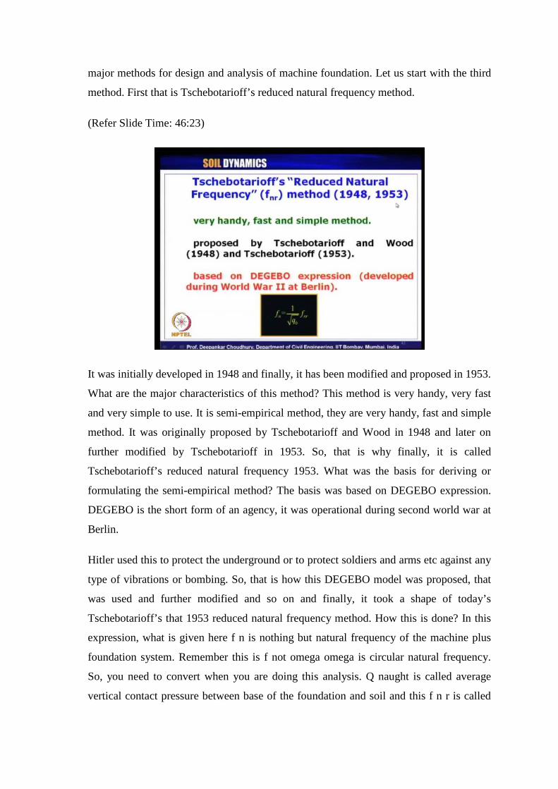
major methods for design and analysis of machine foundation. Let us start with the third
method. First that is Tschebotarioff’s reduced natural frequency method.
(Refer Slide Time: 46:23)
It was initially developed in 1948 and finally, it has been modified and proposed in 1953.
What are the major characteristics of this method? This method is very handy, very fast
and very simple to use. It is semi-empirical method, they are very handy, fast and simple
method. It was originally proposed by Tschebotarioff and Wood in 1948 and later on
further modified by Tschebotarioff in 1953. So, that is why finally, it is called
Tschebotarioff’s reduced natural frequency 1953. What was the basis for deriving or
formulating the semi-empirical method? The basis was based on DEGEBO expression.
DEGEBO is the short form of an agency, it was operational during second world war at
Berlin.
Hitler used this to protect the underground or to protect soldiers and arms etc against any
type of vibrations or bombing. So, that is how this DEGEBO model was proposed, that
was used and further modified and so on and finally, it took a shape of today’s
Tschebotarioff’s that 1953 reduced natural frequency method. How this is done? In this
expression, what is given here f n is nothing but natural frequency of the machine plus
foundation system. Remember this is f not omega omega is circular natural frequency.
So, you need to convert when you are doing this analysis. Q naught is called average
vertical contact pressure between base of the foundation and soil and this f n r is called

reduced natural frequency. That is what I have mentioned here f n r. f n r is known as
reduced natural frequency as was proposed by Tschebotarioff. Now, let us see what is
the use of this method.
(Refer Slide Time: 49:17)
Now, natural frequency how the natural frequency is calculated? We all know omega n is
nothing but root over K by m. So, when we are talking about f n it will be omega n by 2
pi. So, omega n is root over K by m. now, it is K can be represented as K dash times a.
What is K dash? K dash is dynamic modulus of sub grade reaction. So, unit of it will be
in kiloNewton per meter cube. If we are using SI unit but as Tschebotarioff has proposed
this semi empirical method in FPS unit. Let us stick to FPS unit only. So, automatically
the dynamic modulus of sub grade reaction unit will be pound per feet cube. We have
seen how to estimate this K dash.
Earlier we have use the symbol c z, the same thing. In cyclic plate load test we had
computed c z so, that is nothing but same as K dash here dynamic modulus of sub grade
reaction. What is A? A is cross sectional area of the base of the foundation in the unit of
feet square. So, that is why here you are getting the unit of stiffness, that is pound per
feet or kiloNewton per meter, if you use SI unit. So, root over K by m. What is m? m
comprise of mass of the foundation block plus machine and m s is called mass of the
soil, which mass of the soil?

During this vibration when DEGEBO model was proposed, it was proposed that a
portion of the soil is also vibrating along with the machine plus foundation. So, that
portion of the soil which is vibrating along with machine and foundation is the mass of
the soil we should take in this expression. But later on it has been simplified by
Tschebotarioff’s, that is why it is said that Tschebotarioff’s basic model is generated
from the concept of DEGEBO’s model because in DEGEBO’s model if we draw it.
(Refer Slide Time: 52:02)
Suppose, if we have a block type of foundation. So, on top of it we have some machine
here, we have machine plus foundation together some mass m and when it vibrates some
portion of the soil is also getting vibrated along with this. That portion of soil is m s. So,
that is what DEGEBO’s expression it was developed in Germany and it has been now
simplified by Tschebotarioff’s in this fashion. f n can be rewritten this equation, root
over A by W 1 by 2 pi root over K dash W by m plus m s. This W W gets cancelled so, it
remains same root over A by W 1 by 2 pi root over K dash m g by m plus m s. W is the
nothing but weight of the machine plus foundation, which is again further simplified as
root over A by W into 1 by 2 pi into root over K dash by 1 plus m s by m.
Now, this W by A that is weight of machine plus foundation divided by the base area of
the foundation is nothing but our contact pressure, at the base of the foundation. That is
denoted by Q naught as I have said just now, in the previous slide. While explaining this
notation this Q naught is nothing but contact pressure between the foundation base and

the soil weight of the machine plus foundation divided by the area of the foundation. So,
this root over A by W is nothing but 1 by root over Q naught and this entire term that is 1
by 2 pi times root over K dash by 1 plus m s by m is denoted by Tschebotarioff by this
symbol f n r which is called reduced natural frequency. Why it is called reduced natural
frequency?
Because in this case the natural frequency of the machine plus foundation system has
been reduced by considering the effect of the soil, which is also vibrating in face with the
machine plus foundation system. So, that is the reason why this terminology was
proposed by Tschebotarioff that reduced natural frequency and this is the expression f n r
given by Tschebotarioff. Finally f n and f n r are correlated by this simple expression.
What Tschebotarioff’s as given for different type of soil? This K dash value will of
course, depend on your type of soil. This dynamic sub grade modulus of sub grade
reaction depends on type of soil. What type of soil you are using? So, with this we have
come to the end of today’s lecture, we will continue further in our next lecture.