machine tools laboratory (14ame15)
TRANSCRIPT
MT LAB MECHANICAL / IVSEM
1
MACHINE TOOLS LABORATORY
(14AME15)
(For II B.Tech Mechanical Engineering)
DEPARTMENT OF MECHANICAL ENGINEERINGDEPARTMENT OF MECHANICAL ENGINEERINGDEPARTMENT OF MECHANICAL ENGINEERINGDEPARTMENT OF MECHANICAL ENGINEERING
SRI VENKATESWARA COLLEGE OF ENGINEERING &
TECHNOLOGY
R.V.S NAGAR, CHITTOOR-517127
MT LAB MECHANICAL / IVSEM
2
CONTENTS
S.No.
TITLE
PAGE NO.
1 GENARAL INFORMATION 3
2 GENERAL INSTRUCTIONS 4
3 MACHINING PROCESSES 6
4 LIST OF EXPERIMENTS 8
• LATHE MACHINE OPERATIONS
• SHAPING & SLOTING
• DRILLING OPERATIONS
• MILLING OPERATIONS
5 APPENDIX 25

MT LAB MECHANICAL / IVSEM
3
GENERAL INFORMATION
This laboratory is aimed at providing an introduction to the Know-how of common
processes used in industries for manufacturing parts by removal of material in a controlled
manner. Auxiliary methods for machining to desired accuracy is covered. The emphasis
throughout the laboratory course will be on understanding the basic features of the processes
rather than details of constructions of machine, or common practices in manufacturing or
acquiring skill in the operation of machines. Evidently, acquaintance with the machine is
desirable and the laboratory sessions will provide adequate opportunity for this.

MT LAB MECHANICAL / IVSEM
4
GENERAL INSTRUCTIONS AND SAFETY RULES
1. Students should wear the uniform and closed foot wear. Students inappropriately dressed
for lab, at the instructor’s discretion, be denied access).
2. When you handle chemicals wear eye protection (chemical splash goggles or full face
shield).
3. When you work with furnaces for heat treatment procedures or other thermally activated
equipment you should use special gloves to protect your hands.
4. To protect clothing from chemical damage or other dirt, wear a lab apron or lab coat.
Long hair should be tied back to keep it from coming into contact with lab chemicals or
flames.
5. In case of injury (cut, burn, fire etc.) notify the instructor immediately.
6. In case of a fire or imminently dangerous situation, notify everyone who may be affected
immediately; be sure the lab instructor is also notified.
7. If chemicals splash into someone's eyes act quickly and get them into the eye wash
station, do not wait for the instructor.
8. In case of a serious cut, stop blood flow using direct pressure using a clean towel, notify
the lab instructor immediately.
9. Eating, drinking and smoking are prohibited in the laboratory at all times.
10. Never work in the laboratory without proper supervision by an instructor.
11. Never carry out unauthorized experiments. Come to the laboratory prepared. If you are
unsure about what to do, please ask the instructor.
12. Except the scientific calculator, any other electronic devices are not permitted to use
inside the Laboratory.
13. Any damage to any of the equipment/instrument/machine caused due to carelessness, the
cost will be fully recovered from the individual (or) group of students.

MT LAB MECHANICAL / IVSEM
5
MACHINING PROCESSES
MACHINING PROCESSES Machining is one of the processes of manufacturing in
which the specified shape to the work piece is imparted by removing surplus material.
Conventionally this surplus material from the work piece is removed in the form of chips by
interacting the work piece with an appropriate tool. This mechanical generation of chips can be
carried out by single point or multi point tools or by abrasive operations these are summarized
below:
Machining Processes
Single point tool operations Multi-point tool operations Abrasive operations
1. Turning 1. Milling 1. Grinding
2. Boring 2.Drilling 2. Lapping
3. Shaping 3. Tapping 3. Honing
4. Planing 4. Reaming 4. Super-finishing
5. Hobbing
6. Broaching
7. Sawing
The process of chip formation in metal cutting is affected by relative motion between the
tool and the work piece achieved with the aid of a device called machine tool. This relative
motion can be obtained by a combination of rotary and translatory movements of either the tool
or the workpiece or both. The kind of surface that is produced by the operation depends on the
shape of the tool and the path it traverses through the materials. When the workpiece is rotated
about an axis and the tool is traversed in a definite path relative to the axis, a surface of
revolution is generated. When the tool path is parallel to the axis, the surface generated is a
cylinder as in straight turning (Fig.1.) or boring (Fig.2.) operations. Similarly, planes may be
generated by a series of straight cuts without rotating the work piece as in shaping and planning
operations (Fig.3). In shaping the tool is reciprocating and the work piece is moved crosswise at
the end of each stroke. Planning is done by reciprocating the work piece and crosswise
movement is provided to the tool. Surface may be machined by the tools having a number of
cutting edges that can cut successively through the work piece materials. In plane milling, the
cutter revolves and moves over the work piece as shown (Fig.4). The axis of the cutter is parallel
to the surface generated. Similarly in drilling, the drill may turn and be fed into the work piece of
the workpiece may revolve while the drill is fed into it (Fig.5). The machine tools, in general,
provide two kinds of relative motions. The primary motion is responsible for the cutting action
and absorbs most of the power required to perform the machining action. The secondary motion
of the feed motion may proceed in steps or continuously and absorbs only a fraction of the total
power required for machining. When the secondary motion is added to the primary motion,
machine surfaces of desired geometric characteristics are produced. . Consider a situation where
both the cutting motions as well as the feed motion (provided at the end of each stroke) are
rectilinear but perpendicular to each other. Here the machined surface produced is a plane. The
MT LAB MECHANICAL / IVSEM
6
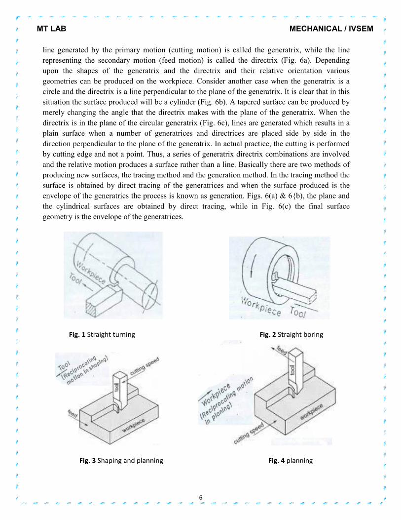
line generated by the primary motion (cutting motion) is called the generatrix, while the line
representing the secondary motion (feed motion) is called the directrix (Fig. 6a). Depending
upon the shapes of the generatrix and the directrix and their relative orientation various
geometries can be produced on the workpiece. Consider another case when the generatrix is a
circle and the directrix is a line perpendicular to the plane of the generatrix. It is clear that in this
situation the surface produced will be a cylinder (Fig. 6b). A tapered surface can be produced by
merely changing the angle that the directrix makes with the plane of the generatrix. When the
directrix is in the plane of the circular generatrix (Fig. 6c), lines are generated which results in a
plain surface when a number of generatrices and directrices are placed side by side in the
direction perpendicular to the plane of the generatrix. In actual practice, the cutting is performed
by cutting edge and not a point. Thus, a series of generatrix directrix combinations are involved
and the relative motion produces a surface rather than a line. Basically there are two methods of
producing new surfaces, the tracing method and the generation method. In the tracing method the
surface is obtained by direct tracing of the generatrices and when the surface produced is the
envelope of the generatrics the process is known as generation. Figs. 6(a) & 6{b), the plane and
the cylindrical surfaces are obtained by direct tracing, while in Fig. 6(c) the final surface
geometry is the envelope of the generatrices.
Fig. 1 Straight turning Fig. 2 Straight boring
Fig. 3 Shaping and planning Fig. 4 planning

MT LAB MECHANICAL / IVSEM
7
Fig. 5 Drilling
Fig.6 Concept of generatrix and directrix. (a) Rectilinear generatrix and directrix.
(b) Directrix perpendicular to the plane of generatrix.
(c) Directrix in the plane of generatrix.

MT LAB MECHANICAL / IVSEM
8
LIST OF EXPERIMENTS
S.No.
NAME OF THE EXPERIMENT
PAGE No.
DATE OF
Exp.
FACULTY
SIGNATURE
LATHE MACHINE OPERATIONS
1
STEP TURNING AND TAPER TURNING
2
KNURLING AND THREAD CUTTING
SHAPING & SLOTING
3
CONVERSION OF CIRCULAR ROD
INTO SQUARE ROD
4
SLOT MAKING
DRILLING OPERATIONS
5
DRILLING AND TAPPING
MILLING
6
SPUR GEAR CUTTING
MT LAB MECHANICAL / IVSEM
9
Experiment No. Date:
STEP TURNING AND TAPER TURNING
AIM
To perform various lathe operations such as facing, plain turning, step turning and taper
turning on a given material made of Mild steel.
MATERIAL REQUIRED
A mild steel bar of 25 mm diameter and 100 mm length.
TOOLS AND EQUIPMENT USED
H.S.S. single point cutting tool,
Chuck key,
Tool post key,
Outside caliper,
Steel rule.
SEQUENCE OF OPERATIONS
1. Facing H.S.S Single Point tool
2. Rough turning H.S.S Single Point tool
3. Finish turning H.S.S Single Point tool
4. Step turning H.S.S Single Point tool
5. Taper turning H.S.S Single Point tool
PROCEDURE
• The work piece is fixed in a 3 – jaw chuck with sufficient overhang.
• Adjust the machine to run the job to a required cutting speed.
• Fix the cutting tool in the tool post and centering operation is performed so that the axis
of the job coincides with the lathe axis.
• Give the feed and depth of cut to the cutting tool.
• Facing operation is performed from the center of the job towards outwards or from the
circumference towards the center.
• Plain turning operation is performed until the diameter of the work piece reduces to 23
mm.
• Check the dimensions by using vernier calipers.
• Perform the plain turning operation on the same work piece for the required length in
order to reduce the diameter to 18 mm so as to get the step turning.
• Using a V – cutting tool grooving operation is performed according to the given
dimensions and finishes the groove using parting tool.

MT LAB MECHANICAL / IVSEM
10
• Swivel the compound slide to the required angle and perform taper turning operation by
rotating the compound slide wheel.
• The angle can be measured by using the formula Tanα = (D – d) / 2L.
• Finally check the dimensions by using vernier calipers.
PRECAUTIONS
• The work piece should be held rigidly in the chuck before operating the machine.
• Tool should be properly ground, fixed at correct height and properly secured, and work
also be firmly secured.
• Before operating the machine see whether the job and tool is firmly secured in devices or
not.
• Optimum machining conditions should be maintained.
• Chips should not be allowed to wound around a revolving job and cleared as often as
possible
• Apply cutting fluids to the tool and work piece properly.
MODEL CALCULATIONS
The amount by which the compound rest has to be swivel is estimated using the taper
angle. Taper angle is calculated as follows.
Taper angle (α) = Tan-1(� – �)
��
Where,
D = Diameter of bigger end, mm
d = Diameter of smaller end, mm
L = Length of taper, mm

MT LAB MECHANICAL / IVSEM
11
SKECTH
RESULT:

MT LAB MECHANICAL / IVSEM
12
Experiment No. Date:
KURNLING AND THREAD CUTTING
AIM
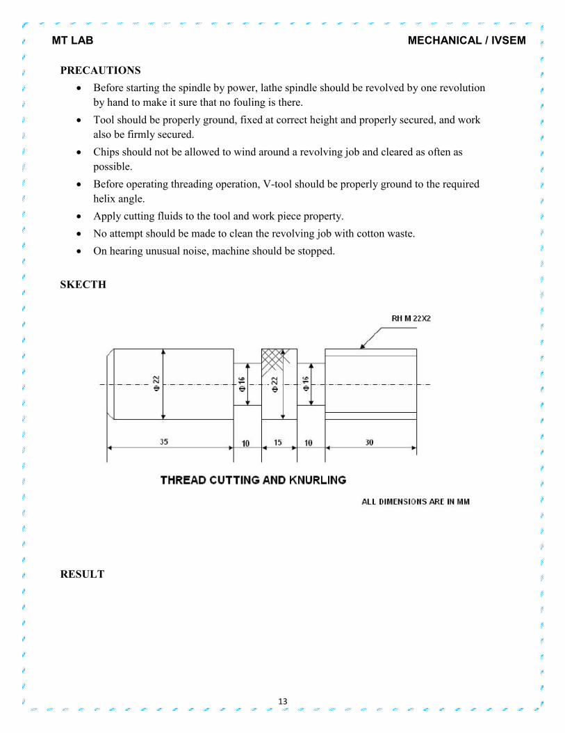
To perform Thread cutting and Knurling operation on the given work piece.
MATERIAL REQUIRED
Mild Steel rod of 25 mm diameter and 100 mm long
TOOLS REQUIRED
Vernier calipers,
Steel rule,
Spanner,
Shuck spanner
H.S.S. single point cutting tool
PROCEDURE
• The work piece is fixed in a 3 – jaw chuck with sufficient overhang.
• Adjust the machine to run the job to required cutting speed.
• Fix the cutting tool in the tool post and centering operation is performed so that the axis
of the job coincides with the lathe axis.
• Facing is performed by giving longitudinal depth of cut and cross feed.
• Perform plain turning operation until the diameter of the work piece reduced to 20mm.
• Using V-cutting tool and parting off tool perform grooving operation to the required
dimensions.
• Reduce speed of the spindle by engaging back gear and use Tumbler feed reversing
mechanism to transmit power through the lead screw.
• And calculate the change gears for the required pitch to be made on the work piece.
• Using half nut mechanism perform thread cutting operation(right hand threading)
according to the given dimensions and continues it until required depth of cut is obtained.
• At the same speed knurling operation is performed using knurling tool.
• For every operation check the dimensions using vernier calipers.
MT LAB MECHANICAL / IVSEM
13
PRECAUTIONS
• Before starting the spindle by power, lathe spindle should be revolved by one revolution
by hand to make it sure that no fouling is there.
• Tool should be properly ground, fixed at correct height and properly secured, and work
also be firmly secured.
• Chips should not be allowed to wind around a revolving job and cleared as often as
possible.
• Before operating threading operation, V-tool should be properly ground to the required
helix angle.
• Apply cutting fluids to the tool and work piece property.
• No attempt should be made to clean the revolving job with cotton waste.
• On hearing unusual noise, machine should be stopped.
SKECTH
RESULT

MT LAB MECHANICAL / IVSEM
14
Experiment No. Date:
DRILLING AND TAPPINNIG
AIM
To perform drilling, and tapping operations on the given M.S Flat work piece.
APPARATUS
1. Drilling Machine with standard accessories
2. Work piece
MATERIAL
Mild Steel flat plate 50 mm × 50 mm ×10 mm
PROCEDURE
• The given work piece is first filed to get required length, breadth and thickness wet chalk is
applied on four sides and with the scriber lines are drawn to get center hole at required location.
• The centers are punched with a Punch and hammer.
• The work piece is fixed firmly in the vice of the Drilling Machine
• 3/8” drill bit is fixed firmly in the chuck and drilling is performed giving uniform depths.
• The drill bit is removed from the drill chuck and is replaced by a reamer.
• The reaming operation is performed on the hole which has been previously drilled.
• The work is removed from the vice for performing tapping operation.
• The job is fixed firmly in a bench vice.
• Tap is fixed in the tap handle and pressure applied on the taps to obtain internal thread.
PRECAUTIONS
• Reaper should be free from moisture
• Marking is done without parallax error
• Care should be taken while cutting and drilling.
• While performing drilling and tapping operations lubricant should be used to minimize the
friction.

MT LAB MECHANICAL / IVSEM
15
SKECTH
RESULT
MT LAB MECHANICAL / IVSEM
16
Experiment No. Date:
CONVERSION OF CIRCULAR ROD INTO SQUARE ROD
AIM
To perform shaping operation of given mild steel rod.
MATERIAL REQUIRED
A Mild steel rod of 25 mm diameter and 100 mm length.
MACHINNE REQUIRED
Shaper machine
CUTTING TOOLS
H.S.S.Tool bit of the required slot size.
SEQUENCE OF OPERATIONS
1 .Fix the specimen in the machine vice
2 .By giving the required feed and depth of cut, the required cut is being made progressively.
PROCEDURE
• Dimension of the work piece is measured and made to the required dimensions.
• fix the job in vice and adjust the tool in the tool head.
• Start the machine during forward stroke only remove the material and during the return stroke is
idle.
• 4. Do the operation to get one side completely flat then repeat the process on four sides of the
work piece.
• Rotate the job after completion of each side is flat.
• Then check the flat ness by using slip gauges. To get the required component.
PRECAUTION:
� Choose proper feed and depth of cut.
� Feed should be controlle4d to avoid to any damage to the cutting tool.
� Fix the work piece is properly into the vice.
� During cutting to supply coolant in between to the work piece and tool.
� Adjust the stroke length properly.

MT LAB MECHANICAL / IVSEM
17
RESULT

MT LAB MECHANICAL / IVSEM
18
Experiment No. Date:
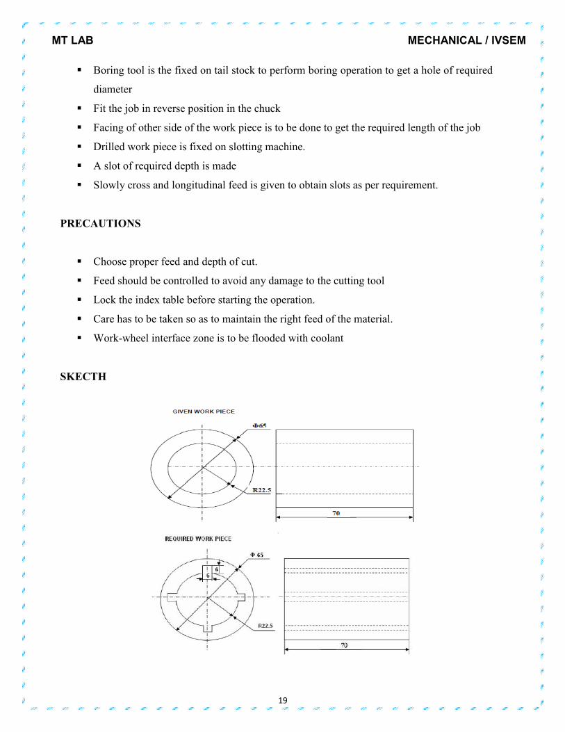
SLOT MAKING
AIM
To make a slot on the given work piece.
MATERIALS REQUIRED
M.S Round Block, Wooden Block
MACHINE REQUIRED
Slotting machine
MEASURING INSTRUMENTS
Vernier calipers slip gauges.
CUTTING TOOLS
H.S.S.Tool bit of the required slot size.
SEQUENCE OF OPERATIONS
• Fix the specimen in the three-jaw chuck of the slotting machine
• By giving the required feed and depth of cut, the required slot is being made
progressively
PROCEDURE
� Fix the work piece in the head stock chuck firmly
� Turning tool is fixed in the tool post and centering is to be done
� Turn the job to get a diameter of required length
� Facing is to be done on one side of the job
� Drill bit of 8 mm diameter is fixed on tail stock and centering of workPiece is to be done
by feeding through tail stock.
� Drill bit of 25 mm diameter is fixed in tail stock
� Drill through a hole of 25 mm diameter in the work piece feeding the tailstock.
MT LAB MECHANICAL / IVSEM
19
� Boring tool is the fixed on tail stock to perform boring operation to get a hole of required
diameter
� Fit the job in reverse position in the chuck
� Facing of other side of the work piece is to be done to get the required length of the job
� Drilled work piece is fixed on slotting machine.
� A slot of required depth is made
� Slowly cross and longitudinal feed is given to obtain slots as per requirement.
PRECAUTIONS
� Choose proper feed and depth of cut.
� Feed should be controlled to avoid any damage to the cutting tool
� Lock the index table before starting the operation.
� Care has to be taken so as to maintain the right feed of the material.
� Work-wheel interface zone is to be flooded with coolant
SKECTH

MT LAB MECHANICAL / IVSEM
20
RESULT

MT LAB MECHANICAL / IVSEM
21
Experiment No. Date:
SPUR GEAR CUTTING
AIM
To perform plane milling operation on the given specimen (mild steel)
MATERIALS REQUIRED
Mild steel specimen.
MACHINE REQUIRED
Milling machine
MEASURING INSTRUMENTS
Vernier calipers
CUTTING TOOLS
Plane (face) milling cutter
MARKING TOOLS
Steel rule, scriber
a. Work holding fixtures: work piece supporting fixtures
b. Miscellaneous tools: Hammer, brush, Allen keys
SEQUENCE OF OPERATIONS
i. Measuring of specimen
ii. Fixing of specimen in the milling m/c.
iii. Giving the correct depth and automatic feed cut thespecimen
iv. Check the specimen with Vernier caliper at the end.
MT LAB MECHANICAL / IVSEM
22
PROCEDURE
� Select and cut a piece of stock to make the blank. Allow at least 1/8 inch excess material
on the diameter and thickness of the blank for cleanup cuts.
� Mount the stock in a chuck on a lathe. At the center of the blank, face an area slightly
larger the than the diameter of the required bore.
� Drill and bore to the required size (within tolerance). Remove the blank from the lathe
and press it on a mandrel.
� Set up the mandrel on the milling machine between the centers of the index head and the
footstock. Dial in within tolerance.
� Select a involute gear cutter and mount and center it. Set the index head to index 24
divisions. Start the milling machine spindle and move the table up until the cutter just
touches the gear blank.
� Set the micrometer collar on the vertical feed handwheel to zero, then hand feed the table
up toward the cutter slightly less than the whole depth of the tooth. Cut one tooth groove.
� Then index the work piece for one division and take another cut. Check the tooth
dimensions with a vernier gear tooth caliper as described previously.
� Make the required adjustments to provide an accurately “sized” tooth. Continue indexing
and cutting until the teeth are cut around the circumference of the work piece.
� The top surface of the job is milled in stages; giving finish cuts towards the end such that,
the height of the job is exactly 40 mm.
� The burrs if any along the edges are removed with the help of the flat file.
MODEL CALCULATIONS
Indexing Ratio =
Where, n = No. of slots on the periphery of the indexing plate.
N = Required number of divisions
Direct Indexing
Indexing Ratio = ��
Where N= required number of divisions
MT LAB MECHANICAL / IVSEM
23
Simple Indexing
Number of holes to move = ��
Where N= required number of divisions
Standard Brown and Sharp Index Plates
No.1: 15, 16, 17, 18, 19, 20
No.2: 21, 23, 27, 31, 33
No.3: 37, 39, 41, 43, 47, 49
Example: It is required to divide the periphery of a job into 60 divisions.
Crank Movement (Indexing Ratio) according to simple Indexing = 40/60 = 2/3
�
=
�
×
�
� =
��
��
The crank has to move 12 holes on 18 holes circle.
PRECAUTIONS
� The milling machine must be stopped before setting up or removing a work piece, cutter
or other accessory
� Never stop the feeding of job when the cutting operation is going on, otherwise the tool
will cut deeper at the point where feed is stopped.
� All the chips should be removed from the cutter. A wiping cloth should be placed on the
cutter to protect the hands. The cutter should be rotated in the clockwise direction only
for right handed tools.
� The work piece and cutter should be kept as cool as possible (i.e. coolant should be used
where necessary to minimize heat absorption).
� The table surface should be protected with a wiping cloth.
� Tool must be mounted as close to the machine spindle as possible.

MT LAB
RESULT
MECHANIC
24
MECHANICAL / IVSEM
MT LAB MECHANICAL / IVSEM
25
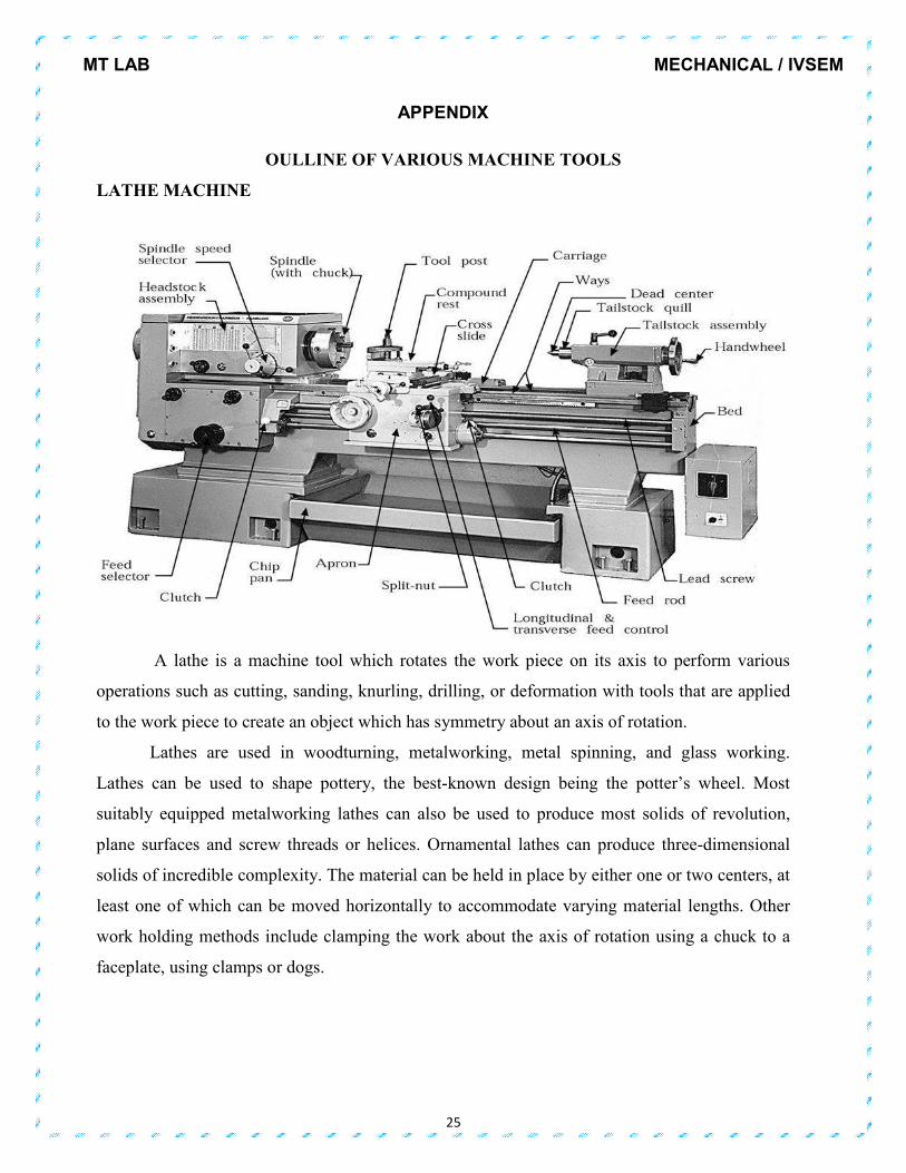
APPENDIX
OULLINE OF VARIOUS MACHINE TOOLS
LATHE MACHINE
A lathe is a machine tool which rotates the work piece on its axis to perform various
operations such as cutting, sanding, knurling, drilling, or deformation with tools that are applied
to the work piece to create an object which has symmetry about an axis of rotation.
Lathes are used in woodturning, metalworking, metal spinning, and glass working.
Lathes can be used to shape pottery, the best-known design being the potter’s wheel. Most
suitably equipped metalworking lathes can also be used to produce most solids of revolution,
plane surfaces and screw threads or helices. Ornamental lathes can produce three-dimensional
solids of incredible complexity. The material can be held in place by either one or two centers, at
least one of which can be moved horizontally to accommodate varying material lengths. Other
work holding methods include clamping the work about the axis of rotation using a chuck to a
faceplate, using clamps or dogs.

MT LAB
SHAPER MACHINE
A shaper is a type of machine tool that uses linear relative motion between the
and a single-point cutting tool to machine a linear tool path. Its cut is
lathe, except that it is linear instead of helical. (Adding axes of
paths, as also done in helical planning.) A shaper is
the cutter riding a ram that moves above
piece moving beneath the cutter. The ram is mo
column; hydraulically actuated shapers also exist.
MECHANIC
26
e of machine tool that uses linear relative motion between the
point cutting tool to machine a linear tool path. Its cut is an analogous to that of a
lathe, except that it is linear instead of helical. (Adding axes of motion can yie
paths, as also done in helical planning.) A shaper is analogous to a planner, but smaller, and with
the cutter riding a ram that moves above a stationary work piece, rather than the entire work
The ram is moved back and forth typically by a crank inside the
actuated shapers also exist.
MECHANICAL / IVSEM
e of machine tool that uses linear relative motion between the work piece
logous to that of a
motion can yield helical tool
ner, but smaller, and with
piece, rather than the entire work
ved back and forth typically by a crank inside the

MT LAB MECHANICAL / IVSEM
27
PLANER MACHINE
A planer is a type of metalworking machine tool that uses linear relative motion between
the work piece and a single-point cutting tool to machine a linear tool path. Its cut is analogous
to that of a lathe, except that it is linear instead of helical. (Adding axes of motion can yield
helical tool paths; see "Helical planing"below.) A planer is analogous to a shaper, but larger, and
with the entire work piece moving on a table beneath the cutter, instead of the cutter riding a ram
that moves above a stationary work piece. The table is moved back and forth on the bed beneath
the cutting head either by mechanical means, such as a rack and pinion drive or a lead screw, or
by a hydraulic cylinder.
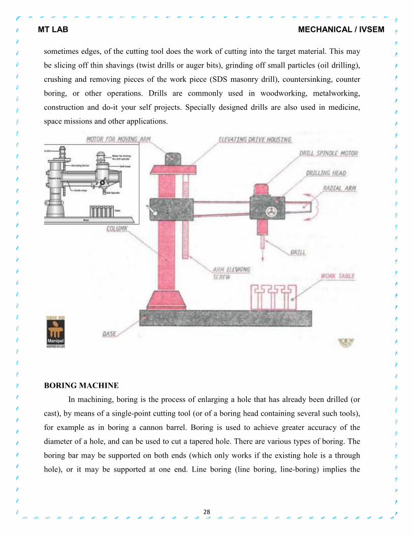
DRILLING MACHINE
A drill or drill motor is a tool fitted with a cutting tool attachment or driving tool
attachment, usually a drill bit or driver bit, used for drilling holes in various materials or
fastening various materials together with the use of fasteners. The attachment is gripped by a
chuck at one end of the drill and rotated while pressed against the target material. The tip, and
MT LAB MECHANICAL / IVSEM
28
sometimes edges, of the cutting tool does the work of cutting into the target material. This may
be slicing off thin shavings (twist drills or auger bits), grinding off small particles (oil drilling),
crushing and removing pieces of the work piece (SDS masonry drill), countersinking, counter
boring, or other operations. Drills are commonly used in woodworking, metalworking,
construction and do-it your self projects. Specially designed drills are also used in medicine,
space missions and other applications.
BORING MACHINE
In machining, boring is the process of enlarging a hole that has already been drilled (or
cast), by means of a single-point cutting tool (or of a boring head containing several such tools),
for example as in boring a cannon barrel. Boring is used to achieve greater accuracy of the
diameter of a hole, and can be used to cut a tapered hole. There are various types of boring. The
boring bar may be supported on both ends (which only works if the existing hole is a through
hole), or it may be supported at one end. Line boring (line boring, line-boring) implies the

MT LAB MECHANICAL / IVSEM
29
former. Back boring is the process of reaching through an existing hole and then boring on the
"back" side of the work piece (relative to the machine headstock).
MILLING MACHINE
MT LAB MECHANICAL / IVSEM
30
A milling machine (also see synonyms below) is a machine tool used to machine solid
materials. Milling machines are often classed in two basic forms, horizontal and vertical, which
refers to the orientation of the main spindle. Both types range in size from small, bench-mounted
devices to room-sized machines. Unlike a drill press, this holds the work piece stationary as the
drill moves axially to penetrate the material, milling machines also move the work piece radially
against the rotating milling cutter, which cuts on its sides as well as its tip. Work piece and cutter
movement are precisely controlled to less than 0.001 in (0.025 mm), usually by means of
precision ground slides and lead screws or analogous technology. Milling machines may be
manually operated, mechanically automated, or digitally automated via computer numerical
control (CNC).Milling machines can perform a vast number of operations, from simple (e.g., slot
and keyway cutting, planning, drilling) to complex (e.g., contouring, die sinking). Cutting fluid is
often pumped to the cutting site to cool and lubricate the cut and to wash away the resulting
swarf.
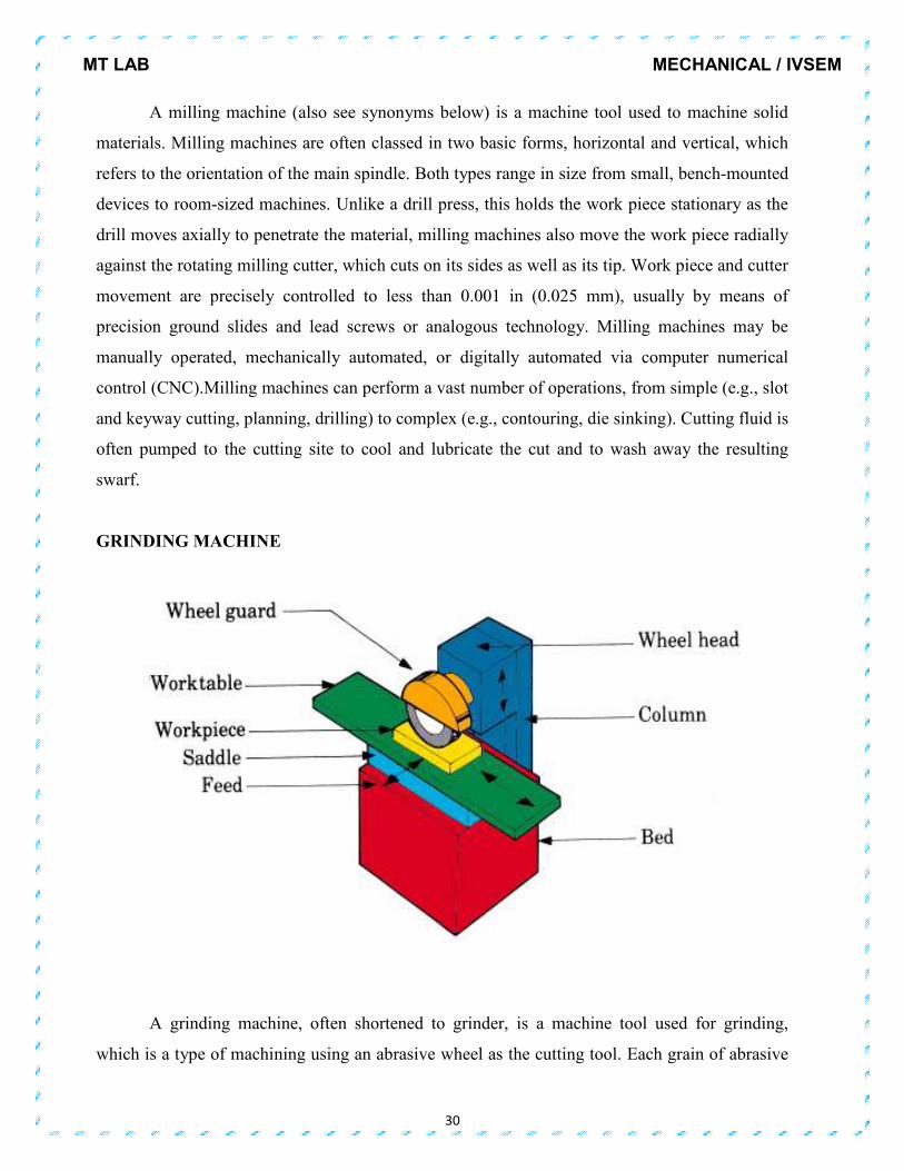
GRINDING MACHINE
A grinding machine, often shortened to grinder, is a machine tool used for grinding,
which is a type of machining using an abrasive wheel as the cutting tool. Each grain of abrasive

MT LAB MECHANICAL / IVSEM
31
on the wheel's surface cuts a small chip from the work piece via shear deformation. The grinding
machine consists of a power driven grinding wheel spinning at the required speed (which is
determined by the wheel’s diameter and manufacturer’s rating, usually by a formula) and a bed
with a fixture to guide and hold the work piece. The grinding head can be controlled to travel
across a fixed work piece or the work piece can be moved whilst the grind head stays in a fixed
position. Very fine control of the grinding head or tables position is possible using a Vernier
calibrated hand wheel, or using the features of numerical controls.