machine tools and fixtures - nasa · sectors in cutting position (a), collapsed within drill stem...
TRANSCRIPT

NASA SP-5910 (05)
MACHINE TOOLS AND FIXTURES
'(NASA-SP-5910(05)) MACHINE TOOLS AND N74-30964FIXTURES: A COMPILATION TechnologyUtilization (NASA) 27 p HC $1.00- CSC 13 Unclas
CSCL 131 UnclasG1/15 46301
A COMPILATION
V. S. A.
asarewramus1 slnaaa lemlM T HN EV a
https://ntrs.nasa.gov/search.jsp?R=19740022851 2019-04-10T06:42:04+00:00Z
Foreword
The National Aeronautics and Space Administration and the Atomic Energy Com-mission have established a Technology Utilization Program for the dissemination ofinformation on technological developments which have potential utility outside theaerospace and nuclear communities. By encouraging multiple application of the resultsof their research and development, NASA and AEC earn for the public an increasedreturn on the investment in aerospace and nuclear research and development programs.
This Compilation is one of a series of documents intended to present such informa-tion. It includes a collection of innovations developed by NASA, AEC, and theircontractors concerning tools, adaptors, jigs, and fixtures useful in machining a widevariety of materials. The Compilation is divided into three sections. Section Onedescribes a variety of machine tools allowing new approaches to special or unique jobs.The second section presents a number of adaptations that extend the usefulness ofstandard machine tools. Section Three features a collection of jigs and fixtures thatpermit the use of standard machine tools in unusual or difficult situations.
Additional technical information on individual devices and techniques can berequested by circling the appropriate number on the Reader Service Card included inthis Compilation.
The latest patent information available at the final preparation of this Compilationis presented on the page following the last article in the text. For those innovations onwhich NASA and AEC have decided not to apply for a patent, a Patent Statement is notincluded. Potential users of items described herein should consult the cognizantorganization for updated patent information at that time.
We appreciate comment by readers and welcome hearing about the relevance andutility of the information in this Compilation.
Jeffrey T. Hamilton, DirectorTechnology Utilization OfficeNational Aeronautics and Space Administration
NOTICE * This document was prepared under the sponsorship of the National Aeronautics and SpaceAdministration. Neither the United States Government nor any person acting on behalf of the UnitedStates Government assumes any liability resulting from the use of the information contained in thisdocument, or warrants that such use will be free from privately owned rights.
For sale by the National Technical Information Service, Springfield, Virginia 22151. $1.00
i

Contents
PageSECTION 1. MACHINE TOOLS
Low-Cost Orbiting Grinder for Cutting Ducts ..................... 1Vee-Notch Tool Cuts Specimens ............................... 2Machining Blind Holes in Stainless Steel .......................... 3
SECTION 2. MACHINE TOOL ADAPTATIONSCore Drill's Bit Is Replaceable Without Withdrawal of Drill Stem:
A Concept ............................................ 4Mechanism for Orienting the Modular Weld Head ................... 6Bond-Drill Tool for Attachment Flanges in Stainless-Steel
Honeycomb Panels ..................................... 8Improved Design for Oil-Film Dynamic-Slip Table ................... 10In-Place Welding-Head Power Transmission ....................... 11Adjustable Drill Bar Replaces Complex Jigs ....................... 12In-Place Welding-Head Simplification ........................... 13Lathe Collet Adapters ..................................... 14Lubricating Strap for Lathe Steady Rest ......................... 14Improved Portable Milling Tool ............................... 15
SECTION 3. JIGS AND FIXTURESFlexible-Line Compression Tool ............................... 16Optical Alignment of Electrodes on Electrical
Discharge Machines ..................................... 17Weight Distributing Base for Level Machine-Tool Support:
A Concept ........................................... 18Circular Holder for Swivel Base ............................... 19Fixtur-e Extends Range of Small Indexig a . ................... .20Weld Beveling of Large-Diameter Pipes ........................... 21Bonding Retort Holders for Cold Plating ......................... 22Threading-Tool Holder .............................. ....... 23Threading-Tool Grinder Fixture ................................... 24Bulkhead Machining Fixture: A Concept ......................... 24
PATENT INFORMATION ..................................... 25

Section 1. Machine Tools
LOW-COST ORBITING GRINDER FOR CUTTING DUCTS
Vertical-Position Side Block Cutting-
Nut AdjustKnob
Pivot Block
Air Motor
Tool MainArm Support
Shaft
Wobble Plate
Wall ofGrinding Gid DuctWheel
Cutting Plane , Expandable14 Plug
Adjustment
SphericalBearing
Portable Grinder
A new grinder has been designed for cutting ducts, nut at the end of the main support shaft. AngularIt is relatively inexpensive, simple, and portable. adjustment is made by tightening or loosening theThe machine is suitable for straight and offset, "on- three screws in the wobble plate. The grinding wheelthe-spot" cutting, and can cut heat-treated alloys is then fed into the duct by tightening the cutting-without extra jigs, fixtures, or hand tools. adjust knob and is orbited around the duct repeatedly
The machine consists of an abrasive wheel, powered until separation occurs.by a small high-speed air motor. The motor is This device can be adapted to differently sizedsupported by an expandable plug that is mounted ducts by using various chuck plates and tool arms,inside the duct (see figure). Conventionally, such and can save considerable time and money.operations have been carried out with hacksaws andfiles. Source: E. J. Lang of
After the cutting plane has been established and Rockwell International Corp.scribed on the duct surface, a support plug is inserted under contract tointo the duct and secured by means of expanding Marshall Space Flight Centerwedges. A small high-speed air motor with a directly- (MFS-20684)mounted grinding wheel is installed on the tool armin the approximate cutting location. Axial adjustment Circle 1 on Reader Service Card.is made by tightening or loosening a vertical-position
1

2 MACHINE TOOLS AND FIXTURES
VEE-NOTCH TOOL CUTS SPECIMENS
60° ±15 '
Detail-Specimen Vee-Notch
Slot to Prevent l i Triple-Edged Specimen
Deflection Cutter
Spring Collets
Carriage AdjustmentWheel
Carriage
Vee-Notch Cutter in Use
This Vee-notch cutting tool, for use on tensile activated by an electrically driven bellcrank (notspecimens, (see figure)' costs less, is easier to set up, shown), causes the triple-edged cutter to oscillate upand is more precise than similar existing equipment. and down. Simultaneous turning of the carriage
The cutter is rigidly mounted in a slot of similar adjustment wheel moves the specimen against theshape to prevent deflection during the cutting oper- cutter blade. The triangular shape of the cutteration. Since no expensive equipment is required, the allows the use of carbide tips for notching heat-tool can be mounted on a stand or table and operated treated or abrasive materials as well as exotic alloysby laboratory technicians. contemplated for use in structures subjected to high
The cutter is hollow ground on the end, so that stresses. Furthermore, the tool can be adapted toall three edges can be used before resharpening. other types of notching and/or light duty punchingSince neither the carriage nor the cutter can be of holes or slots.deflected, the Vee-notch is uniformly positioned inrelation to the holes. In addition, spring collets are Source: R. A. Spierprovided for positioning of the specimen from the Marshall Space Flight Centerexisting holes. This precise positioning eliminates (MFS-20730)misalignment of opposed notches that could becaused by variations in the hole size. A rocker, Circle 2 on Reader Service Card.

MACHINE TOOLS 3
MACHINING BLIND HOLES IN STAINLESS STEEL
Five 0.152 + 0.0025-cm (0.060 + 0.001-in.) di- (7.5-in.) carbide tube,with a copper electrode solderedameter, blind, longitudinal holes, 125 diameters deep, to the tip and forms the holes by electrical-dischargehad to be machined into the flat end of a 304 machining (EDM). The tube holds the electrode instainless-steel sounding-rocket nose probe. Tolerance place rigidly and channels a flow of dielectricfor the location of holes was 0.0127 cm (0.005 in.). flushing oil through the tubular electrode to theEach hole had to intersect a 0.10-cm (0.04-in.) hole point where the electric-discharge erosion takes place.in the rounded tip of the probe. Each of those four A small copper wire in the mbuth of the electrodeholes, equally spaced from the center hole, was erodes away the stainless-steel core, which is leftrequired to angle outward 450 off the center line of inside as the electrode progresses. The electrode isthe mating 0.15-cm hole. Specified tolerances could attached to the spindle of the EDM machine by twonot be met with any known drilling or boring perpendicular dovetail slides followed by a ball joint.method. The slides permit the upper end of the electrode,
To meet this requirement, a new machining tool the ball joint, and the lower end of the electrode tohas been developed (see figure). It employs a 19-cm be centered. The nose probe is positioned under the
spindle by the movable work table of the EDMFlushing-m ne. The nose probe and electrode are submerged
SL in dielectric oil after adjustment. With the electrode
EOM rotating at 20 rpm, a 65-kHz, 60-V, 0.8-A dischargeMachine between the electrode and the nose probe erodes aSpindle straight cylindrical hole in the 304 stainless steel in
the same manner as a boring bar.The following precautions must be taken if accu-
rate machining is to be obtained:BallJo 1. The carbide tube must be lapped straight to
prevent it from touching the sides of the hole.2. To assure proper alignment, the copper electrode
should be machined to size after it has beensoldered to the carbide tube.
3. The EDM must be isolated from any motors,pumps, etc., that could cause vibration in theelectrode.
4. Clean dielectric flushing oil must be used. DirtNose Probe
(Rounded Tip will cause excessive overcut.Down)
Source: Anthony Walch, Jr., andEdmund Smigocki
Goddard Space Flight Center(GSC-10545)
EDM Equipment No further documentation is available.

4
Section 2. Machine Tool Adaptations
CORE DRILL'S BIT IS REPLACEABLE WITHOUT WITHDRAWAL OF DRILL STEM:A CONCEPT
U jL L U L
L U L u I L U L
Figure 1. Sectors in Cutting Position (a), Collapsed within Drill Stem (U above L) (b), inTransverse Section (c), and Viewed from the Inside, as if Flattened from X-X (d).
A new concept for drill bits allows a deep hole cumstances one ring is enough). Here described is a six-to be drilled in the earth for recovery of a core sector bit with two assembly rings for drilling of awithout withdrawing the drill stem for replacement 4.763-cm (1.875-in.) diameter hole and recovery of aof dulled bits. 3.493-cm (1.375-in.) diameter core.
The bit is divided into several sectors (see Figure 1). Figure 1 shows that when the three "upper" (U)When the bit assembly is collapsed, its outside sectors slide upward relative to the three "lower"diameter is small enough for it to be forced down (L) sectors the outside diameter of the collapsed bit isthe drill stem; when it reaches bottom, the sectors smaller than the inner diameter of the drill stem.are forced outward and together to form a cutting Around the inner tube are two sliding assembly rings;bit (Figure 2a). For drilling, all sectors are clamped the U-sectors are attached to the top ring by leafbetween the drill stem and a longitudinally movable springs; the L-sectors, are similarly attached to theinner tube that is part of the insertion and withdrawal bottom ring. The springs tend to spring the sectorsassembly. The clamped portion of each sector can be inward.thinner than the cutting face. A dulled bit is retracted With the inner tube drawn upward relative to theby reversal of this procedure. assembly rings and the sectors sprung inward by the
With two or more assembly rings, as many bit sec- springs, the bit assembly is placed within the drilltors as are needed may be used (in certain special cir- stem and forced to the bottom. When the L-sectors

MACHINE TOOL ADAPTATIONS 5
Drill Stem Hammer Guide
Hammer Cable
Inner Tube Unlatching Cable
Top Assembly RingHammer
Latch
Bottom Assembly Ring
Stop Shelf on Inner Tube
Leaf Spring AttachingSector to Ring
Assembly Ring's Finger
Stop Shelf on Inner Tube
Stop Shelf on Drill Stem
Bit SectorsClamped Portion of Bit
Seat can be Tapered
Sectored Bit
a b c
Figure 2. Bit Locked for Drilling (a), Beginning of Removal; Sector Sprung Inward (b),Hammer Mechanism and Bit Assembly Sliding through Drill Stem (c).
reach drilling depth, their assembly ring is stopped A dulled bit is withdrawn from the hole by reversalwhen its finger engages a shelf on the inner surface of of this procedure. As the inner tube is pulled upward,the stem. As the inner tube continues downward, it unclamps the sectors, allowing them to springthe top assembly ring is stopped by its finger when inward. The stops force the assembly rings with thethe U-sectors are at drilling depth. Finally the inner sectors attached upward. A hammer mechanism istube is forced further downward until its outer stops used for insertion or withdrawal of a bit. Hammeringengage the shelf on the stem, thus forcing the may be upward or downward (Figure 2c).sectors outward and clamping them between the tube Source: F. C. Rushing and A. B. Simon of
and the stem. Drilling torque is transmitted by fric- Westinghouse Electric Corp.tion between sectors and stem; the interfacial surfaces under contract to
can be roughened if necessary. Specific orientation of Marshall Space Flight Centerthe bit is unnecessary,but all parts of the bit assembly (MFS-20819)are angularly keyed by vertical grooves in the innertube's stop ring. No further documentation is available.

6 MACHINE TOOLS AND FIXTURES
MECHANISM FOR ORIENTING THE MODULAR WELD HEAD
The new tilt mechanism permits a tungsten/inert (3) an inert-gas supply source; andgas (TIG) orbital welder to efficiently weld ducts that (4) a welding head which contains the mechancialhave mismatched abutting ends. The device tilts the and electrical elements required to produce themodular welder by adjusting cantilevered arms extend- weld. The weld head responds to control signalsing from the weld support member. Thus, the from the weld programmer and provides feed-carrier head of the welder follows the abutted back signals to the programmer to ensuremismatch of two ducts. compliance with the weld schedule.
The all-automatic system consists of four basic Figure 1 shows the weld-head assembly positionedelements: to join ducting mounted in a support fixture. Figure2
(1) a welding power supply (not shown); shows the weld-head drive mechanism, which. is(2) a weld programmer (not shown), which auto- located in back of the weld-head assembly. The
matically controls and synchronizes all welding output gear of the weld-head drive motor (Figure 1)process functions as predetermined by an es-tablished weld schedule;
Figure 1.Weld-Head Assembly

MACHINE TOOL ADAPTATIONS 7
Wire ld-H ead Drive Mechanism
Radius of engages t he drive-motor track (Figure 2). The drive-Gyration 1.50 Mrack. motor track is stationary and drives the weld head and
electrode (as commanded by the weld programmer),at any of five available ranges of fixture speed:0.1 to 0.3 rpm; 0.1 to 0.5 rpm; 0.1 to 0.9 rpm;
/ 0.1 to 1.7 rpm; and 0.1 to 3.3 rpm. The duct-contour sensors (Figure 1) send impulses to anelectrode oscillator. The impulses cause the electrodeto oscillate through a plane normal to the direction
S Nulof weld travel and through a radius of gyration of 1.5S Null Position arc minutes at a double amplitude of 50.8 cm/min.
Weld Joint (20 in./min.) (Figure 3). The wire-feed controller
-7' delivers the filler wire at a rate matching the selectedfixture speed.
Double Source: L. W. Spiro of
20-In. Min. Rockwell International Corp.under contract to
Marshall Space Flight Center(MFS-19095)
Figure 3. Electrode Oscillation Circle 3 on Reader Service Card.

8 MACHINE TOOLS AND FIXTURES
BOND-DRILL TOOL FOR ATTACHMENT FLANGESIN STAINLESS-STEEL HONEYCOMB PANELS
Tee-Handle I I Lower Fiber Block
Nut /Bonded in Sub-Assembly
Upper
Fiber LerBlock
BokClamp Plate
Tee-HandleWasher
Upper Flange
Lower Flange
Tee-HandleClamp Tool
Figure 1. Conventional Tee-Handle Clamp
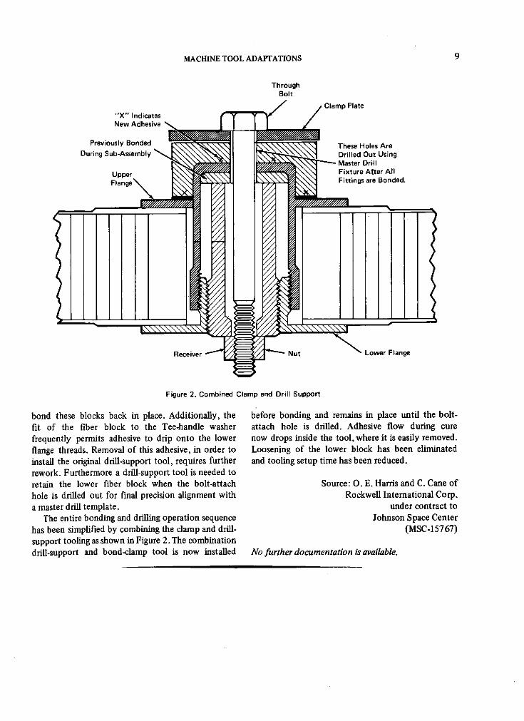
In many applications, stainless-steel honeycomb Figure 1 shows a conventional Tee-handle clamppanels require impact-load-carrying attachment flanges previously used to secure the upper fiber blocks andfor mounting related components. A combined clamp shim plates for bonding. In many cases the lowerand drill support serves as a stable, stress-free means fiber block has broken loose during removal of thisof supporting the flanges in place while adhesives are clamp. Since the flanges cannot be removed at thisapplied and drilling is accomplished. point, a difficult rework operation is required to
MACHINE TOOL ADAPTATIONS 9
ThroughBolt
Clamp Plate"X" IndicatesNew Adhesive N
Previously Bonded These Holes AreDuring Sub-Assembly Drilled Out Using
Master Drill
Upper Fixture Atter All
Flange Fittings are Bonded.
Receiver Nut Lower Flange
Figure 2. Combined Clamp and Drill Support
bond these blocks back in place. Additionally, the before bonding and remains in place until the bolt-fit of the fiber block to the Tee-handle washer attach hole is drilled. Adhesive flow during curefrequently permits adhesive to drip onto the lower now drops inside the tool, where it is easily removed.
flange threads. Removal of this adhesive, in order to Loosening of the lower block has been eliminated
install the original drill-support tool, requires further and tooling setup time has been reduced.rework. Furthermore a drill-support tool is needed toretain the lower fiber block when the bolt-attach Source: O. E. Harris and C. Cane ofhole is drilled out for final precision alignment with Rockwell International Corp.a master drill template. under contract to
The entire bonding and drilling operation sequence Johnson Space Centerhas been simplified by combining the clamp and drill- (MSC-15767)support tooling as shown in Figure 2. The combinationdrill-support and bond-clamp tool is now installed No further documentation is available.

10 MACHINE TOOLS AND FIXTURES
IMPROVED DESIGN FOR OIL-FILM DYNAMIC-SLIP TABLE
An oil-film dynamic-slip table has been constructed covered with relatively thin plates (Figure 1) whichfor use in a large vibration-test laboratory. Its have holes drilled on equidistant centers to indexunique design eliminates a great deal of machining with the grooves. The covered grooves are drilled,and reduces the amount of hydraulic tubing required. tapped, and plugged at one end and are drilled andInstead of many long holes for the oil feed, grooves tapped to receive tube fittings at the other end.are machined into the table top which is then Hydraulic lines (Figure 2) are attached to the tube
Figure 1. Improved Slip Table
Figure 2. Hydraulic Lines for Slip Table
MACHINE TOOL ADAPTATIONS 11
fittings and supply oil to the holes in the top plate Source: J. A. Gustafson andfrom a pump and sump beneath the table. Excess oil E. C. Reinhardt offlows over the edges of the table and into a drainage Rockwell International Corp.channel that directs it back into the sump. The table under contract tois easily cleaned by removing the cover plates and J6hnson Space Centerflushing out the grooves. (MSC-17839)
No further documentation is available.
IN-PLACE WELDING-HEAD POWER TRANSMISSION
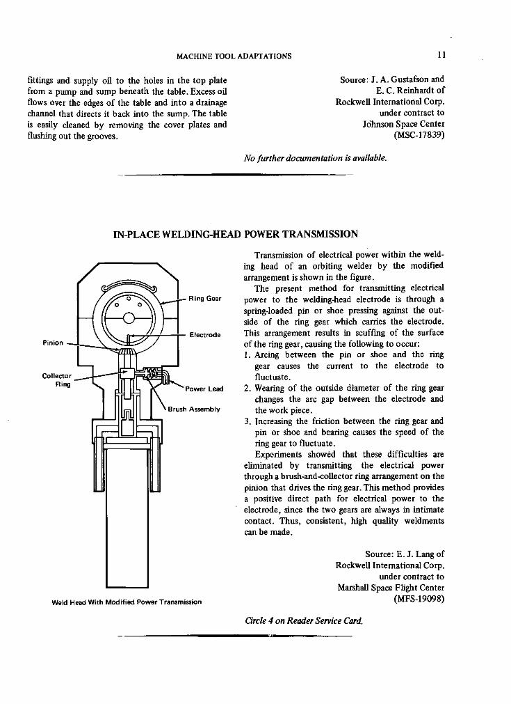
Transmission of electrical power within the weld-ing head of an orbiting welder by the modifiedarrangement is shown in the figure.
The present method for transmitting electricalSRing Gear power to the welding-head electrode is through a
spring-loaded pin or shoe pressing against the out-side of the ring gear which carries the electrode.
Electrode This arrangement results in scuffing of the surfacePinion - of the ring gear, causing the following to occur:
1. Arcing between the pin or shoe and the ringgear causes the current to the electrode to
Collector fluctuate.Ring Power Lead 2. Wearing of the outside diameter of the ring gear
changes the arc gap between the electrode andBrush Assembly the work piece.
3. Increasing the friction between the ring gear andpin or shoe and bearing causes the speed of thering gear to fluctuate.Experiments showed that these difficulties are
eliminated by transmitting the electrical powerthrough a brush-and-collector ring arrangement on thepinion that drives the ring gear. This method providesa positive direct path for electrical power to theelectrode, since the two gears are always in intimatecontact. Thus, consistent, high quality weldmentscan be made.
Source: E. J. Lang ofRockwell International Corp.
under contract toMarshall Space Flight Center
Weld Head With Modified Power Transmission (MFS-19098)
Circle 4 on Reader Service Card.

12 MACHINE TOOLS AND FIXTURES
ADJUSTABLE DRILL BAR REPLACES COMPLEX JIGS
Figure 1. Previous Method
Figure 2. Adjustable Drill Bar
The complex jigs (see Figure 1) used in the past The desired hole pattern is obtained by making a
for precision drilling on large surfaces took ap- drill plate from an engineering drawing. A three-hole,
preciable time and put a premium on the skill of the 900 25.4-cm (10-in.) increment grid is made, and thesetup man. The adjustable drill bar shown in Figure 2 stationary member is fastened to one side of this gridincorporates a micrometer screw which, when used and held in place by the two hold-downs. The ma-
in conjunction with standard gauge blocks, provides chined ways permit the movable member of the as-
a rapid method of drill hole location. sembly to slide to any position within its range. By

MACHINE TOOL ADAPTATIONS 13
using an appropriate gauge block, the selected drill Source: J. H. Coventry ofhole in the movable member can be placed precisely Rockwell International Corp.on the workpiece with the micrometer screw. under contract to
This versatile device picks up oddly dimensioned Johnson Space Centertool hole points and acts as a sine drill bar. (MSC-15624)
No further documentation is available.
IN-PLACE WELDING-HEAD SIMPLIFICATION
/Modified Weld-Head Body
I I I _IrI
Pinion Assembly n
Modified MotorMount
U - I Split Coupling.Motor Half
Purge Pipe r-Installed withMicarta Shear Pin
Tygon TubingModifiedPower Lead
Modified SmallWeld-Head Motor
Modified Pipe Welder
A modification to an orbital-head pipe-welder head body, the motor mount, and the small weld-reduces the number of motors necessary to operate head motor.the equipment for various sizes and diameters of pipe.Changes on the welding-head motor mount and the Source: E. J. Lang ofmotor-mounting flange permit a single motor to be Rockwell International Corp.used with both small and large in-place welding under contract toheads. Marshall Space Flight Center
The modified welding head is shown in the (MFS-19097)figure. The primary modifications are the weld-
Circle 5 on Reader Service Card.

14 MACHINE TOOLS AND FIXTURES
LATHE COLLET ADAPTERS
Different makes of lathes require unalike methodsRear Rotating Draw Ring
of attaching the collet chuck holder to the spindle. Adapter Tightens ColletsA large number of collet chuck holders and colletchucks are required to maintain a complete selection
Smallof chucks for each machine. Size
By using front-and-rear adapters (see figure) collet Colletchucks of different sizes (5c, 3c, etc.) may be usedin a single collet holder. The steel adapters permit theoperator to change different lathe setups quickly.
Source: R. Marotte ofRockwell International Corp.
under contract toJohnson Space Center Front Lathe Collet Chuck
(MSC-17509) Adapter
No further documentation is available. Adapters Used With a Small Collet
LUBRICATING STRAP FOR LATHE STEADY REST
Object Being A Teflon strip, used as a lubricating strap on aTurned lathe steady rest, has been found to be effective,
efficient, and durable. This material is practically
Steady Rest friction free, heat resistant, and requires no otherContinuous Teflon lubricant. Due to its characteristics, it automaticallyStrap (1/8" Thick) flows and retracts to maintain a stable bearing. In
0addition, it self-adjusts to the desired radius.As shown in the figure, the Teflon strap is
wrapped around the object being turned. Tests haveshown this dry-lubrication system to be efficientand trouble free, even under severe conditions.
Source: George M. DudleyLangley Research Center
(LAR-10741)
Lathe Bed No further documentation is available.
Lubricating Strap for Lathe Steady Rest

MACHINE TOOL ADAPTATIONS 15
IMPROVED PORTABLE MILLING TOOL
SpeedControl
Head
Clamped 1 Screws U(Y) Travel L
(Feed)
SCross Feed (X)o o Cut Travel
LevelingPlate
Adjusting Screwsto Level Tool to
Workpiece Clamp Cutting Surface
Workpiece /
Figure 1 Head in Down Position
Vacuum Exhaust forChip Removal
Air Exhaust
Cutter Speed
Head Control
HeadSwings
Down Air MotorAir-inlet
Valve
Pivot
Figure 2 Head in Up Position
A leveling X-Y table and a swing-access milling adjusting screws (to level the milling head to thehead have been added to a standard portable milling cutting surface) give this tool the necessary versatilityunit. The tool is shown in Figure 1 with the new for precision work.milling head in the down position, and in Figure 2 Source: J. M. Dimino ofwith the head in the up position. Rockwell International Corp.
This tool is particularly useful for reworking under contract tocomponents in the field, when removal to the shop Johnson Space Centeris not feasible. The swing feature in the milling head, (MSC-15723)in conjunction with the X-Y bed-travel and the NofurtherdocumentationisNo further documentation is available.

16
Section 3. Jigs and Fixtures
FLEXIBLE-LINE COMPRESSION TOOL
Protective Clamp Ring
Steel Mesh
Bellows
BayonetConnector
Operating Lever
Flexible-Line Compression Tool
Flexible (bellows-type) ducts used to transfer steps by operation of a lever). A clamp ring is placedcryogenic liquids within a spacecraft launch vehicle at each end of the flexible duct assembly near theare large and heavy. Installation or removal of these flange. The clamp rings have eyelets to accommodateducts is virtually impossible without some sort of installation of the "come alongs" on either side ofmechanical assists. The ducts are approximately the assembly. As the "come along" operating levers
30.5 cm (12 in.) in diameter, 1.8 to 3.7 m (6 to 12 are manipulated,the bellows are compressed, allowingft) in length and weigh approximately 230 to 270 kg the operator to complete the installation or removal(500 to 600 lbs). In order to provide adequate operation easily and safely.clearance of the bayonet connector which is attachedto the end of the flexible duct, the bellows section Source: Donald J.Ritchie ofmust be compressed from 7.6 to 20 cm (3 to 8 in.) The Boeing Companyduring installation and removal of the duct. under contract to
A flexible-line compression tool (see figure) has Kennedy Space Centerbeen designed to compress the bellows adequately (KSC-06788)and to assist in guiding the duct as tension isapplied by either of the "come alongs", (ratchet andpawl devices which advance a cable or chain in discrete No further documentation is available.

JIGS AND FIXTURES 17
OPTICAL ALIGNMENT OF ELECTRODES ONELECTRICAL DISCHARGE MACHINES
The small electrodes mounted on electrical dis- be magnified by a factor of 6 to 8 while the mag-charge machines must be aligned and true before nification of the length remains fixed.starting the machining operation. Electrodes that The path of motion of the center of the toolare not exactly in alignment with the machine axis holder can be established on the screen as the toolor that are slightly bent will generate cavities that holder is raised and lowered, and a fiducial line canare too large or incorrectly shaped. be scribed on the screen to provide a reference for
Electrode alignment can be assured with a shadow- alignment of the electrode. Since the fiducial linegraph system (see figure) that projects a magnified and the electrode are constantly in view, the processimage on a screen so that the alignment of the of positioning and straightening the electrode canelectrode can be corrected and verified, continue until the operator achieves the requisite
accuracy of alignment. An electrode 12 to 15 cm inlength and 1 mm in diameter can be easily straightenedto a runout well within 0.050 to 0.075 mm.
The optical system makes it possible to machine,in hard materials, very small straight holes to depths
Movable that are limited only by the length of the electrode.Electrode Screen
Light oMoreover, adjustments and corrections of the elec-Source 0 0trode can be made while work is in place, and the
- -shape of the electrode can be readily monitored as*1 machining progresses.
This technique may be adapted to other machine-tool equipment where physical contact with the toolcannot be made during inspection and where access
Fresnel to the tool is so limited that conventional runoutLensImage- checking procedures (such as dial indicators) cannot
Forming Lens be used.-
Shadowgraph System An erecting lens can be placed between the pro-jecting lens system and the screen to cast an up-
The system uses a conventional 500-watt slide right image. Sharp images of the electrodes will beprojector as a light source. A Fresnel lens is posi- obtained only if the projecting lens system is properlytioned between the light source and the electrode to constructed and corrected for aberrations. The screencollect the light into an image-forming lens, or a can be curved to keep all portions of the image inprojecting lens system which forms an image of the focus; the curved screen compensates for opticalelectrode on a movable screen. The screen is placed aberrations due to finite depth of field of the imagingat the position which provides the desired magnifi- lens.cation, but it is usually located fairly close to the Source: A. G. Boissevain andmachine where it can provide a magnification of B. W. Nelsonabout two. If a flat screen is placed at an oblique Ames Research Centerangle to the optical axis of the system, one dimension (XAC-09489)of the image can be effectively magnified more thanthe other; for example, the width of an electrode can Circle 6 on Reader Service Card.

18 MACHINE TOOLS AND FIXTURES
WEIGHT DISTRIBUTING BASE FOR LEVEL MACHINE-TOOL SUPPORT: A CONCEPT
A unique weight distributing base for a machine- (from an expanding concrete) is forced under the
tool support member, such as the leg of a lathe, sole of the foot and retained there by means of a
could be fabricated in situ by the use of a new suitable form until the concrete has set.
variety of concrete that expands, rather than con- Figure 2 shows the end of the leveling screw as it
tracts, on setting. Expansion slightly raises the ends bears upon the floor surface before the concrete
of the leveling screws of the machine from the floor, base has set. The spacing relationship after the
thereby alleviating loss of level and damage to the concrete has set is indicated in Figure 3.
floor from machine vibration.Figure 1 shows a portion of a typical lathe leg,
with a hex-headed leveling screw threaded through Leveling Screwthe foot and a locking nut mounted on the screw.
Lathe Leg
.o oLocking Nut: ..
Foot Leveling Screw * a Spacing
Floor Surface ,
S: - Spacing
Floor Surface End of ScrewEnd of Screw
Figure 1. Typical Lathe LegFigure 3. Spacing After Set
The end of the screw is in contact with the surface
of the floor.After the leveling screws have been adjusted and Source: Wallis M. Tener of
the locking nuts tightened to prevent the screws from Caltech/JPL
changing the initial level setting, a layer of grout under contract toNASA Pasadena Office
Leveling Screw (NPO-10727)
-loor .o .o d icl 7 n er Se :Ctd.
Surface J o *o'"o ::: :
End of Screw . 0
Figure 2 Spaing Before Set
Figure 2. Spacing Before Set

JIGS AND FIXTURES 19
CIRCULAR HOLDER FOR SWIVEL BASE
Wire-ConnectorHolding Device
SwivelingBase Swiveling
Arm-
Center ArmAssembly
Figure 1. Holder Assembly
This novel circular holder has been installed on the The holder permits rapid multiple positioning of aplywood shelf of a large wiring-assembly fixture for standard swivel-base extension arm tool, used to holdassembling complex and extensive wiring harnesses. connectors during their wiring and assembly into the
harness.Figure 1 shows the holder assembly as it appears
when not in use (no connector installed). Figure 2shows the connector and its wire-insertion tool as it
Inserted Wire is used to assemble individual leads into the con-nector. The holder is fastened to the plywood shelfwith wood screws. When a connector is placed in theholding device, the holder can be swiveled 360degrees. This allows the insertion tool to be used toplace wires from all directions.
Source: M. E. Ingles and W. Busser ofnsertion Rockwell International Corp.
STool under contract toJohnson Space Center
(MSC-15879)
Figure 2. Connector and Wire-Insertion ToolNo further documentation is available.

20 MACHINE TOOLS AND FIXTURES
FIXTURE EXTENDS RANGE OF SMALL INDEXING HEAD
Head
Fixture Used to Place Large Ring
Many machine shops are faced with the problem four clamp-on sliding fingers need not be made
of occasionally inspecting or laying out rings larger precisely, because the ring is aligned with the table
than the capacity of their indexing heads. This before clamping.relatively inexpensive work-holding fixture extendsthe range of a small indexing head and permits the Source: J. D. Froman of
layout or inspection of angular spacings around large- Rockwell International Corp.diameter rings (see figure). under contract to
High-precision extension face plates are available Johnson Space Center
for indexing heads and rotary tables, but these are (MSC-17237)expensive and difficult to acquire. The shop aidshown is less expensive and easily fabricated. The No further documentation is available.

JIGS AND FIXTURES 21
WELD BEVELING OF LARGE-DIAMETER PIPES
Drill Mount /
(0.-in)eec.5-rin. Drill
Roller
RadialSlots
/ Load i ng
Handle~/ Spring Steel Plate
Guide Rollers Cut in s Tooi
J-BevelPipe
Jig Used To Bevel A Pipe
The ends of pipes measuring between 15 and 46 cm During operation, the drill is pressed inward to(6 and 18 in.) in diameter can be J-beveled in the proper depth for a rough cut, and is then lockedthe field, in preparation for welding, with a 0.13-cm into position. The jig is slowly rotated until the rough(0.5-in.) electric drill (driving a cutting tool) and cut is complete. The drill is then adjusted for thea newly developed special jig. The technique is finish cut and the jig is rotated again.much faster and accurate than earlier methods. Comparable pipe-beveling tools are described in
The jig consists of a circular steel plate, of about Tech Briefs 68-10551,69-10229, and 69-10231.46 cm (18 in.) in diameter, in which three equidistantslots are radially cut (see figure). A guide roller is Source: R. Liebenstien ofmounted through each slot; one roller is spring-loaded Bendix Corp.to allow for out-of-round pipes, under contract to
With the jig centered over the end of the pipe, Kennedy Space Centerthe rollers are set to fit the pipe's inner surface. (KSC-10550)The drill is mounted over the widest of the slots,and a J-beveling cutter is mounted in the chuck.The drill is so mounted that the cutter bevels the No further documentation is available.end of the outer surface of the pipe.

22 MACHINE TOOLS AND FIXTURES
BONDING RETORT HOLDERS FOR COLD PLATING
Work Clamp / (Telescoping Support Arm
With Adjustable Swivel
K Attachment
Detail B
AdjustableStop Clamp
Retort
Base Stationary
Stop Clamp
1" Beam
Detail A
Retort Holder
A new fi ture has been designed to assist in cold E. Kostyshak and
plating with silver. It protects the cold plate and T. Costanzo ofretort from damage by excessive handling. Because Rockwell International Corp.the fixture is adjustable (see figure), variously sized under contract toretorts may be used and held in a stationary position, Johnson Space Centerreducing the possibility of damage to the plate (MSC-00658)after bonding.
No further documentation is available.
JIGS AND FIXTURES 23
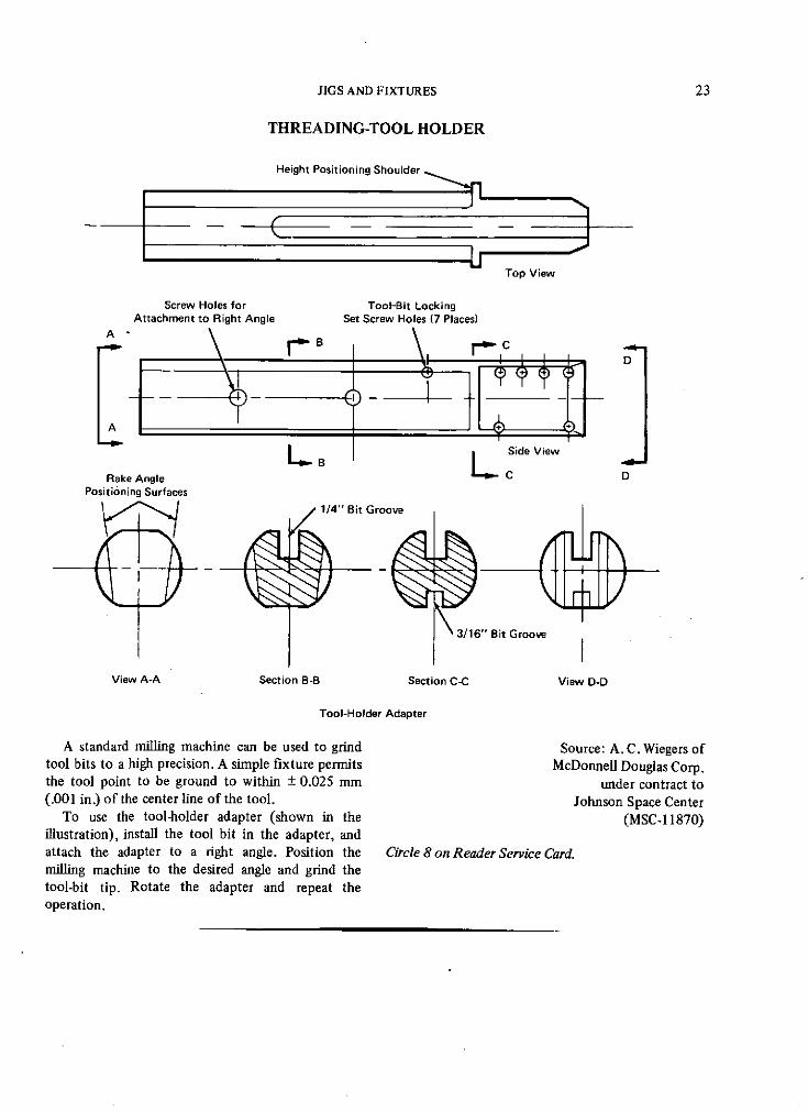
THREADING-TOOL HOLDER
Height Positioning Shoulder
Top View
Screw Holes for Tool-Bit LockingAttachment to Right Angle Set Screw Holes (7 Places)A B
S ID
A
L. L Side View
Rake Angle C DPositioning Surfaces
1/4" Bit Groove
3/16" Bit Groove
View A-A Section B-B Section C-C View D-D
Tool-Holder Adapter
A standard milling machine can be used to grind Source: A. C. Wiegers oftool bits to a high precision. A simple fixture permits McDonnell Douglas Corp.the tool point to be ground to within ± 0.025 mm under contract to(.001 in.) of the center line of the tool. Johnson Space Center
To use the tool-holder adapter (shown in the (MSC-11870)illustration), install the tool bit in the adapter, andattach the adapter to a right angle. Position the Circle 8 on Reader Service Card.milling machine to the desired angle and grind thetool-bit tip. Rotate the adapter and repeat theoperation.

24 MACHINE TOOLS AND FIXTURES
THREADING-TOOL GRINDER FIXTURE
A fixture has been designed and fabricated to The tool is securely held at the proper angle by thehold a thread-cutting tool in the correct position tool-grinding fixture (see figure). First, one surface of
while it is being ground or resharpened. By selecting the cutting edge is ground. Then, without removing
the proper chucking surface, any cutting tool can be the tool from the fixture, the entire assembly is
accurately ground or resharpened to any standard rotated and set in place and the other surface of the
angle, cutting edge is ground.This fixture eliminates guesswork, produces a
precise, high quality cutting edge, and reduces grind-
ing time. It should be of interest to any machineshop.
Source: N. W. Blake andM. A. Anderson of
Rockwell International Corp.under contract to
Johnson Space Center(MSC-15052)
Circle 9 on Reader Service Card.Tool-Grinding Fixture
BULKHEAD MACHINING FIXTURE: A CONCEPT
Air Motor Bracket grinding and sanding created excessive debris, and the
Vacuum- plastic bag had to be replaced repeatedly.Transparent Cover Cleaner These drawbacks are eliminated by an air motor,
cDuct mounted on a bracket with a spherical base. The
HVacuumold-Down End Mill motor drives an end mill that efficiently removes the
Clarnps bonded-on items. The base of the unit is held firmlyin place by vacuum hold-down clamps (suction cups).A transparent cover encloses the end mill and work-piece so that the machining may be constantlyobserved. A vacuum-cleaning duct is connected to an
aperture in the transparent cover to remove debris.
Workpiece Source: J. R. Lewis of
Rockwell International Corp.Portable Aft Bulkhead Machine Fixture under contract to
Items bonded onto panel surfaces were previously Johnson Space Center
removed by using a mini-grinder with a sanding disk (MSC-15840)
in a plastic bag. The plastic bag was taped to thebulkhead and around the operator's arms. The No further documentation is available.

25
Patent Information
The following innovations, described in this Compilation, have been patented or
are being considered for patent action as indicated below:
Vee-Notch Tool Cuts Specimens (Page 2) MFS-20730This invention is owned by NASA, and a patent application has been filed. Inquiries
concerning nonexclusive or exclusive license for its commercial development should be
addressed to:Patent CounselNASA HeadquartersCode GPWashington, D. C. 20546
Core Drill's Bit is Replaceable Without Withdrawal of Drill Stem: A Concept (Page 4)MFS-20819
Title to this invention has been waived under the provisions of the National
Aeronautics and Space Act [42 U.S.C. 2457 (f)], to the Westinghouse Electric Corp.,
Friendship International Airport, P.O. Box 746, Baltimore, Md. 21203
Optical Alignment of Electrodes on Electrical Discharge Machines (Page 17) XAC-09489This is the invention of a NASA employee, and U.S. Patent No. 3,565,530 has
been issued to him. Inquiries concerning license for its commercial development may be
addressed to the inventors: Mr. A. G. Boissevain and Mr. B. W. Nelson, Ames Research
Center, Mail Stop FQ 277-9, NASA, Moffett Field, California 94035.