machine design, vol.7(2015) no.4, issn 1821-1259 pp. 125-128 · jovan doric, ivan klinar: influence...
TRANSCRIPT

machine design, Vol.7(2015) No.4, ISSN 1821-1259 pp. 125-128
*Correspondence Author’s Address: University of Novi sad, Faculty of Technical Sciences, Trg Dositeja Obradovica 6, 21000 Novi Sad, Serbia, [email protected]
Research paper
INFLUENCE OF CONROD LENGTH ON WEAR OF I.C. ENGINE CRANKSHAFT BEARING Jovan DORIĆ1,* - Ivan KLINAR1
1 University of Novi sad, Faculty of Technical Sciences, Novi Sad, Serbia
Received (14.11.2015); Revised (15.12.2015); Accepted (20.12.2015) Abstract: In this article was examined influence of the ratio between piston rod length and crank radius on wear diagram of I.C. engine crankshaft bearing. Since crankshaft main journals belong to a group of highest loaded engine parts, it is very important to know forces acting on them. If a polar load diagram for each main journal is known, then the forces are fully defined. The importance of field examinations of bearing failures due to wear is very well known and in this article we try to find relation between kinematic rod ratio and forces on crankshaft. In this way, a useful approach has been defined for determining how various engine and crankshaft parameters affect a cumulative load and theoretical wear profiles of journal bearings, and can be used in the process of bearing and lubrication system design. Key words: I.C. engine, wear, polar diagram 1. INTRODUCTION
Today's trends of IC engines development going towards reduction of engine size and displacement. The last couple year has seen a flurry of petrol powered medium-sized vehicles downsizing from their usual six cylinders to just four. Downsizing is a simple concept, replace a larger engine with a smaller version, with a lower displacement. The downsized engines of tomorrow will have fewer, smaller cylinders, so the volume swept by pistons as they pump up and down inside is reduced. This will reduce friction, thermal losses and the mass moved, boosting fuel economy and cutting carbon dioxide emissions. The engine that powered first car built by carl Benz 140 years ago developed a power of 0,6 kW with displacement of about liter. Today’s automotive engine have power density of more than 100 kW per liter. These achievements of larger engine power from the same or smaller engine displacement are possible due application of higher pressure in cylinder engine. Higher pressure of gas in cylinder generate larger load on engine bearing. In downsizing engine bearing area is smaller than in naturally aspirated engine with same power. Thus, bearings in such modern engine have to withstand much harsher conditions. 2. MAIN ENGINE CONSTRUCTION Ordinary engine consist of several main moving parts (shown on Fig.1). During engine operating processes pressure from combustion chamber generate force on piton top. This piston force together with inertial forces generate force in connecting rod which produce tangential force on crankshaft. Bearing on crankshaft are under extremely load during WOT (Wide Open Throttle) regimes. It is very important that during every working regimes there is hydrodynamic lubrication film between crankshaft and journal bearing.
Fig.1. Main engine parts The conrod is the element that connects the piston with the engine crankshaft and converts linear into circular motion. It consists of a small end, body and big end. The small end attaches to the piston pin, gudgeon pin or wrist pin, which is currently most often press fit into the conrod but can swivel in the piston, a "floating wrist pin" design. The big end connects to the bearing journal on the crank throw, in most engines running on replaceable bearing shells accessible via the connecting rod bolts which hold the bearing "cap" onto the big end. Typically there is a pinhole bored through the bearing and the big end of the connecting rod so that pressurized lubricating motor oils quirts out onto the thrust side of the cylinder wall to lubricate the travel of the pistons and piston rings. The connecting rod is under tremendous stress from the reciprocating load represented by the piston, actually stretching and being compressed with every rotation, and
Jovan Doric, Ivan Klinar: Influence of Conrod Length on Wear of I.C. Engine Crankshaft Bearing; Machine Design, Vol.7(2015) No.4, ISSN 1821-1259; pp. 125-128
126
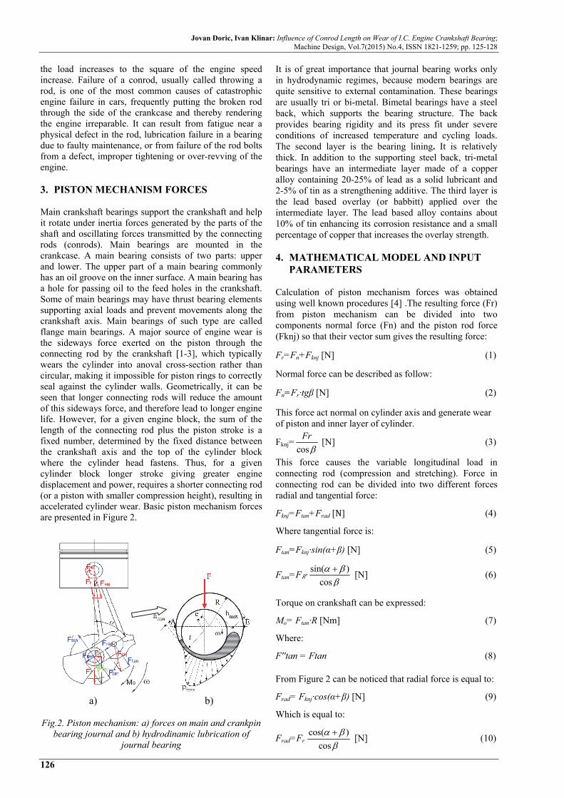
the load increases to the square of the engine speed increase. Failure of a conrod, usually called throwing a rod, is one of the most common causes of catastrophic engine failure in cars, frequently putting the broken rod through the side of the crankcase and thereby rendering the engine irreparable. It can result from fatigue near a physical defect in the rod, lubrication failure in a bearing due to faulty maintenance, or from failure of the rod bolts from a defect, improper tightening or over-revving of the engine. 3. PISTON MECHANISM FORCES Main crankshaft bearings support the crankshaft and help it rotate under inertia forces generated by the parts of the shaft and oscillating forces transmitted by the connecting rods (conrods). Main bearings are mounted in the crankcase. A main bearing consists of two parts: upper and lower. The upper part of a main bearing commonly has an oil groove on the inner surface. A main bearing has a hole for passing oil to the feed holes in the crankshaft. Some of main bearings may have thrust bearing elements supporting axial loads and prevent movements along the crankshaft axis. Main bearings of such type are called flange main bearings. A major source of engine wear is the sideways force exerted on the piston through the connecting rod by the crankshaft [1-3], which typically wears the cylinder into anoval cross-section rather than circular, making it impossible for piston rings to correctly seal against the cylinder walls. Geometrically, it can be seen that longer connecting rods will reduce the amount of this sideways force, and therefore lead to longer engine life. However, for a given engine block, the sum of the length of the connecting rod plus the piston stroke is a fixed number, determined by the fixed distance between the crankshaft axis and the top of the cylinder block where the cylinder head fastens. Thus, for a given cylinder block longer stroke giving greater engine displacement and power, requires a shorter connecting rod (or a piston with smaller compression height), resulting in accelerated cylinder wear. Basic piston mechanism forces are presented in Figure 2.
a) b)
Fig.2. Piston mechanism: a) forces on main and crankpin
bearing journal and b) hydrodinamic lubrication of journal bearing
It is of great importance that journal bearing works only in hydrodynamic regimes, because modern bearings are quite sensitive to external contamination. These bearings are usually tri or bi-metal. Bimetal bearings have a steel back, which supports the bearing structure. The back provides bearing rigidity and its press fit under severe conditions of increased temperature and cycling loads. The second layer is the bearing lining. It is relatively thick. In addition to the supporting steel back, tri-metal bearings have an intermediate layer made of a copper alloy containing 20-25% of lead as a solid lubricant and 2-5% of tin as a strengthening additive. The third layer is the lead based overlay (or babbitt) applied over the intermediate layer. The lead based alloy contains about 10% of tin enhancing its corrosion resistance and a small percentage of copper that increases the overlay strength. 4. MATHEMATICAL MODEL AND INPUT
PARAMETERS Calculation of piston mechanism forces was obtained using well known procedures [4] .The resulting force (Fr) from piston mechanism can be divided into two components normal force (Fn) and the piston rod force (Fknj) so that their vector sum gives the resulting force:
Fr=Fn+Fknj [N] (1)
Normal force can be described as follow:
Fn=Fr·tgβ [N] (2)
This force act normal on cylinder axis and generate wear of piston and inner layer of cylinder.
Fknj=cos
Fr
[N] (3)
This force causes the variable longitudinal load in connecting rod (compression and stretching). Force in connecting rod can be divided into two different forces radial and tangential force:
Fknj=Ftan+Frad [N] (4)
Where tangential force is:
Ftan=Fknj·sin(α+β) [N] (5)
Ftan=F ·sin( )
cos
[N] (6)
Torque on crankshaft can be expressed:
Mo= Ftan·R [Nm] (7)
Where:
F''tan = Ftan (8)
From Figure 2 can be noticed that radial force is equal to:
Frad= Fknj·cos(α+β) [N] (9)
Which is equal to:
Frad=Fr cos( )
cos
[N] (10)

Jovan Doric, Ivan Klinar: Influence of Conrod Length on Wear of I.C. Engine Crankshaft Bearing; Machine Design, Vol.7(2015) No.4, ISSN 1821-1259; pp. 125-128
127
Construction of a journal bearing conditional wear diagram requires a prerequisite to be fulfilled: direction and magnitude of the forces acting on the journal throughout the engine cycle have to be known. The forces are thoroughly defined by a polar load diagram that is thus the source of input data for obtaining a conditional wear diagram. Gas forces and inertia forces of crank gear elements are dominant ones and are taken into account in determining a main journal load [5]. After inserting pressure law (Figure 3), which is result of combustion process, and solving kinematic and dynamic equations we can define main forces in piston mechanism.
Fig.3. PV and Pα diagrams
5. RESULTS On Figure 5 is presented resulting force (Fr) on piston during whole cycle at 5500 rpm for λ=0,3. In this Figure 6 total force (Fr) was obtained through inertial force (Fi) and pressure gas force (Fg). Geometry and mass of piston and conrod are adopted in relation to standard values of conventional petrol engines of 1200 cm3.
Fig.4. Inertal force (Fi) and pressure gas force (Fg) at 5500 rpm and λk=0,3
Polar diagram showing the magnitude of the resultant force on the crankpin. Such diagram was shown on next Figure 5. This represents the load exerted upon a bearing during the course of one complete engine cycle. The system of reference remains fixed in the bearing and is so designed that the central vertical line of the diagram coincides with the central line of the connecting rod in the case of connecting rod bearing, and with the axis of the cylinder in the case of main bearings. Now, we can define polar diagrams for journal bearing at different engine parameters. Comparsion of polar diagrams for different ratio between crank radius and connecting rod length are shown in following Figure 6. Since the amount of wear is proportional to the applied load [6], and the load distribution in the contact zone is not uniform, the bearing wear depth due to the load will
not be uniform either. This is noted on Figure 8 where the half-moon shaped shaded area illustrates the bearing wear depth proportional to the load within the contact zone. It should be emphasized that the term “wear depth” used here does not represent a real depth of the material removed, but it is related to the load. On Figure 7 with Flr is presented total force on journal bearing.
Fig.5. Journal bearing polar load diagram λk=0,25
Fig.6. Comparison of polar diagrams for different kvalues (different ratio of crankshaft radius and conrod
length)

Jovan Doric, Ivan Klinar: Influence of Conrod Length on Wear of I.C. Engine Crankshaft Bearing; Machine Design, Vol.7(2015) No.4, ISSN 1821-1259; pp. 125-128
128
Wear diagrams are designed in accordance with the recommendations with [5]. Finally it is easy to construct wear diagrams for the different choosen parameters of piston mechanism. Such wear diagrams are presented in the following Figure 8.
Fig.7. Determining a worn journal profile
Fig.8. Different wear diagrams in relation to λk
6. CONCLUSION At higher values of λk (lesser length of conrod) most of the load is transferred to the walls of the cylinder and piston which causes increased wear of this parts and vice versa. In addition to this greater length of the connecting rod have a greater mass and the inertia force. In our case, greater length of the conrod gives a lower middle torque although geometrically speaking (smaller angle β for the same angle α) torque has increased. The reasons for this are greater mass and greater inertial force, which reduces the overall mean torque at the output of the crankshaft. As for the lubrication is greater affordability at low normal force of a greater power in the piston rod. This states that the favorable structure with a lower value λ or longer connecting rod.
Wear diagrams of main journals and crankpin bearing journal of an IC engine crankshaft provide a clear visual representation of the journals load. With a help of the diagrams it can very easily and quickly be concluded which journals are higher loaded than others. In addition, it can be seen how a journal is loaded around its circumference. The research presented analysis of impact of conrod length on construction of the wear diagrams. The algorithm has been implemented in computer programs also developed by the authors and thus a very useful tool has been obtained. The results obtained could be used in analyses of how various factors affect main journal load and wear. Furthermore, the analyses could also be conducted on crankshaft main bearings, of course with some modifications of the algorithm and the programs developed, and this could be the subject of a future research. REFERENCES [1] Farzin H. M., Ali F., Stress Analysis and Optimization
of Crankshafts Subject to Dynamic Loading, Final project report, University of Toledo, 2007.
[2] Неиман И. Ш, Динамика авиационных двигателей, Оборонгиз, Москва, 1940.
[3] Koehler R. F. , Verbrennungsmotoren - Motormechanik, Berechnung und Auslegung des Hubkolbenmotors, 4. Auflage, Vieweg & Sohn Verlag, GWV Fachverlage GmbH, Wiesbaden, 2006.
[4] Živković M., Motori sa unutrašnjim sagorevanjem, Mašinski fakultet univerziteta u Beogradu, Beograd, 1976.
[5] Nebojša M. Nikolić, Tripo M. Torović, Života M. Antonić,Jovan Ž. Dorić, An Algorithm for Obtaining Conditional Wear Diagram of IC Engine Crankshaft Main Journals, FME Transactions (2011) 39, pp: 157-164.
[6] Bhushan B., Introduction to Tribology, John Wiley & Sons, Inc., New York, 2002.