machine and assembly runoff specification - news · specification document machine and assembly...
TRANSCRIPT

GM Powertrain
Global Machinery and Equipment
Specification Document
Machine and Assembly Runoff Specification
Document: SP-Q-MARO
Version: G1.0
Published Date: 19-Sep-2008
Specification created and approved by:
Global Manufacturing Engineering Organizations of GM Powertrain
Approval signatures on file at GMPT Global Headquarters Pontiac, MI.

GM Powertrain Manufacturing-Engineering
Document Management Information
Page 2 of 40
Document: SP-Q-MARO Version: G1.0
Published Date: 19-Sep-2008 Print Date: 15-Oct-08
This Specification shall take effect as of the Published Date of the document.
The controlled version of this document is the one stored on the GMPT Machinery and Equipment Specifications web site. Any printed copy is an uncontrolled copy.
Any questions or comments with respect to this specification should be directed to the GMPT Manufacturing Engineer responsible for the project.
Revision History
Published Version Section
Number Change Description & Impact
19-Sep-2008 G1.0 All Approved Global Release.

GM Powertrain Manufacturing-Engineering
Table of Contents
Page 3 of 40
Document: SP-Q-MARO Version: G1.0
Published Date: 19-Sep-2008 Print Date: 15-Oct-08
TABLE OF REGIONAL SPECIFIC REQUIREMENTS .................................................................................................... 4
1.0 INTRODUCTION ................................................................................................................................................... 5
1.1 SCOPE OF DOCUMENT ....................................................................................................................................... 5 1.1.1 Local Range Of Application ............................................................................................................................ 5 1.1.2 Subject-Related Range Of Application ........................................................................................................... 5 1.1.3 Procedural Flowchart for Preliminary Quality Acceptance ............................................................................. 6 1.1.4 Procedural Flowchart for Final Quality Acceptance ........................................................................................ 7
1.2 LEGAL REQUIREMENTS AND REGULATIONS .................................................................................................. 8 1.2.1 ORDER OF PRECEDENCE ........................................................................................................................... 8
1.3 INDUSTRY AND INTERNATIONAL STANDARDS ............................................................................................... 8 1.4 RESOLUTION OF CONFLICT ............................................................................................................................... 8
2.0 DEFINITIONS AND ACRONYMS ......................................................................................................................... 9
3.0 REQUIREMENTS ................................................................................................................................................ 10
3.1 MANAGEMENT OF ACCEPTANCE PROCEDURE ............................................................................................ 10 3.2 PREPARATION ................................................................................................................................................... 10
3.2.1 Part Availability ............................................................................................................................................. 11 3.2.2 Pre-Conditions .............................................................................................................................................. 11
3.3 PRELIMINARY QUALITY ACCEPTANCE (SUPPLIER’S PLANT) ...................................................................... 15 3.3.1 Equipment Pre-Qualification ......................................................................................................................... 15 3.3.2 Capability Run .............................................................................................................................................. 17 3.3.3 Common-Sense Appraisal ............................................................................................................................ 19 3.3.4 Report Generation ........................................................................................................................................ 20 3.3.5 Cutting Tool-Change Capability .................................................................................................................... 20 3.3.6 Important Note For Machine Delivery ........................................................................................................... 21 3.3.7 Equipment Non-Conformance ...................................................................................................................... 21
3.4 SPECIAL CONDITIONS ...................................................................................................................................... 21 3.4.1 General Note ................................................................................................................................................ 21 3.4.2 Special Characteristics Conditions ............................................................................................................... 21 3.4.3 Special Process Conditions - Machining ...................................................................................................... 23 3.4.4 Special Process Conditions - Assembly ....................................................................................................... 31
3.5 FINAL QUALITY ACCEPTANCE (GMPT PLANT) ............................................................................................... 38 3.5.1 General ......................................................................................................................................................... 38 3.5.2 Capability run ................................................................................................................................................ 39
3.6 NOTE FOR FINAL PAYMENT ............................................................................................................................. 40

GM Powertrain Manufacturing-Engineering
Table of Regional Specific Requirements
Page 4 of 40
Document: SP-Q-MARO Version: G1.0
Published Date: 19-Sep-2008 Print Date: 15-Oct-08
TABLE OF REGIONAL SPECIFIC REQUIREMENTS
REGIONAL 1: (NA) SECTION 3.3.1.1 GENERAL .................................................................................................................. 15 REGIONAL 2: (E, NA) SECTION 3.4.3.12.1 EQUIPMENT PRE-QUALIFICATION ....................................................................... 29 REGIONAL 3: (NA) SECTION 3.4.4.8.4 ACCEPTANCE OF THE FASTENING PROCESS AT THE SPINDLE SUPPLIER’S SHOP ....... 34

GM Powertrain Manufacturing-Engineering
Page 5 of 40
Document: SP-Q-MARO Version: G1.0
Published Date: 19-Sep-2008 Print Date: 15-Oct-08
1.0 INTRODUCTION
1.1 SCOPE OF DOCUMENT
1.1.1 Local Range Of Application
This specification shall be applicable to all plants within the scope of responsibility of GMPT. Specifications and rules of the responsible ordering department as well as the respective production unit are to be followed.
1.1.2 Subject-Related Range Of Application
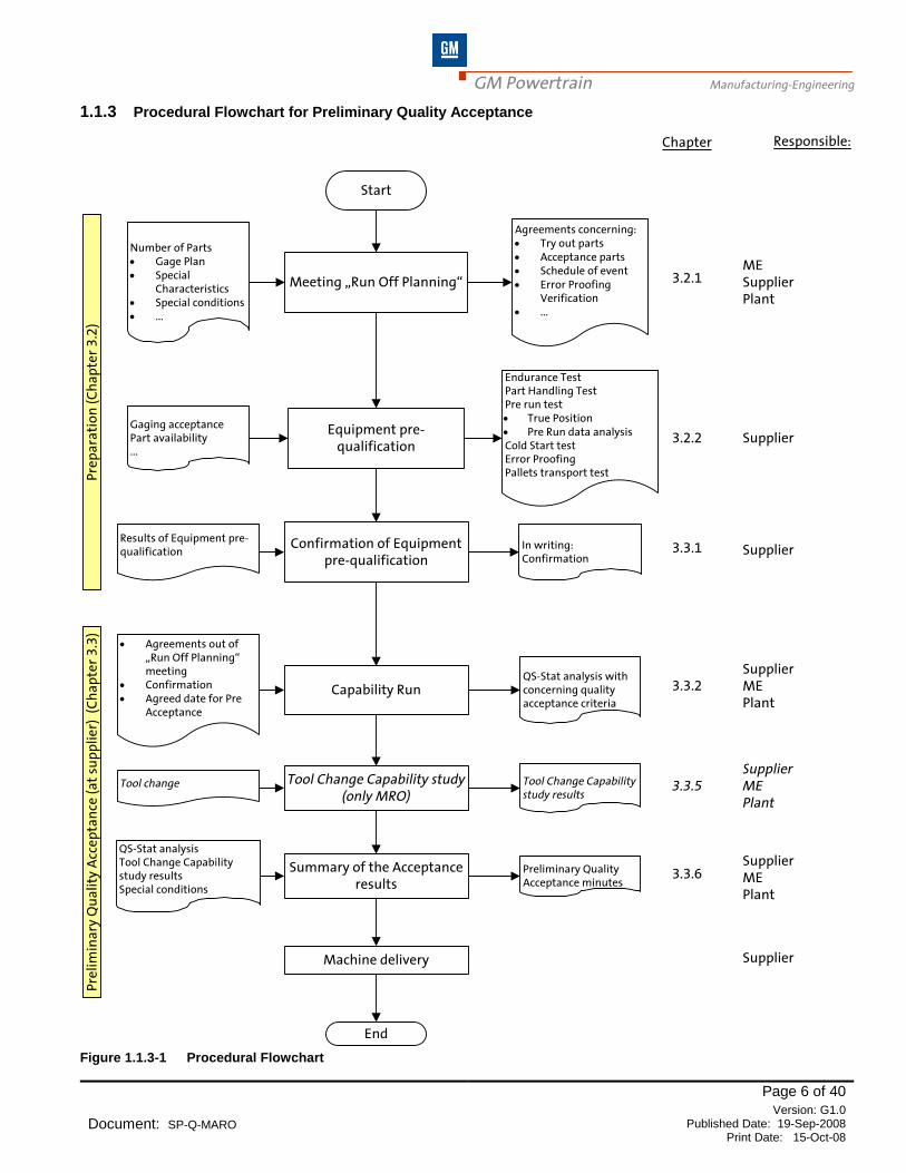
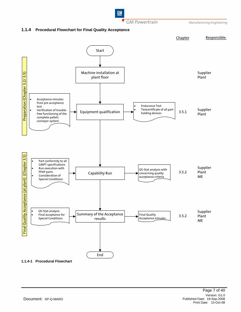
This specification defines the acceptance tests and process capability requirements for manufacturing equipment within GMPT including machining, assembly and test equipment. This shall apply both to the preliminary tests at the Suppliers facility and to the final tests at the customers facility. These acceptance tests must be performed: Prior to the start of operation of any new piece of equipment or machinery, After general overhauls, After essential design modifications and After relocations (including those within the same department). At the time of quotation, the GMPT Manufacturing Engineer requesting the quotation must communicate those characteristics that require the higher acceptance criteria of a KPC/PQC (section 3.3.2.4). The contents of this specification shall therefore be made known to the Suppliers and manufacturers of the production equipment upon placement of the bid or order. Any deviations to this specification must be approved by Powertrain Management and agreed to, with the Supplier, in writing before order placement. Figure 1.1.3-1 Procedural Flowchart and 1.1.4-1 Procedural Flowchart shows schematically the capability evaluation for acceptance of production equipment.
GM Powertrain Manufacturing-Engineering
Page 6 of 40
Document: SP-Q-MARO Version: G1.0
Published Date: 19-Sep-2008 Print Date: 15-Oct-08
1.1.3 Procedural Flowchart for Preliminary Quality Acceptance
Responsible:
Number of Parts· Gage Plan· Special
Characteristics· Special conditions· ...
Meeting „Run Off Planning“
Start
MESupplierPlant
Supplier
Agreements concerning:· Try out parts· Acceptance parts· Schedule of event· Error Proofing
Verification· ...
Chapter
3.2.1
Equipment pre-qualification
Gaging acceptancePart availability...
Endurance TestPart Handling TestPre run test· True Position· Pre Run data analysisCold Start testError ProofingPallets transport test
3.2.2
Pre
pa
rati
on
(C
ha
pte
r 3
.2)
Pre
lim
ina
ry Q
ua
lity
Acc
ep
tan
ce (
at
sup
pli
er)
(C
ha
pte
r 3
.3)
Confirmation of Equipment pre-qualification
Results of Equipment pre-qualification
In writing:Confirmation
Supplier3.3.1
Capability Run
SupplierMEPlant
· Agreements out of „Run Off Planning“ meeting
· Confirmation· Agreed date for Pre
Acceptance
QS-Stat analysis with concerning quality acceptance criteria
Tool Change Capability study (only MRO)
Tool change Tool Change Capability study results
Summary of the Acceptance results
SupplierMEPlant
QS-Stat analysisTool Change Capability study resultsSpecial conditions
Preliminary Quality Acceptance minutes
Machine delivery
SupplierMEPlant
Supplier
3.3.2
3.3.5
3.3.6
End
Figure 1.1.3-1 Procedural Flowchart
GM Powertrain Manufacturing-Engineering
Page 7 of 40
Document: SP-Q-MARO Version: G1.0
Published Date: 19-Sep-2008 Print Date: 15-Oct-08
1.1.4 Procedural Flowchart for Final Quality Acceptance
Responsible:
Machine installation at plant floor
Start
SupplierPlant
Chapter
Equipment qualification
· Acceptance minutes from pre acceptance test
· Verification of trouble-free functioning of the complete pallets conveyor system
· Endurance Test· Testcertificate of all part
holding devices 3.5.1
Pre
pa
rati
on
(C
ha
pte
r 3
.2/
3.5
)Fi
na
l Qu
ali
ty A
cce
pta
nce
(a
t p
lan
t) (
Ch
ap
ter
3.5
)
Capability Run
SupplierPlantME
· Part conformity to all GMPT specifications
· Run execution with PPAP parts
· Consideration of Special Conditions
QS-Stat analysis with concerning quality acceptance criteria
Summary of the Acceptance results
· QS-Stat analysis· Final acceptance for
Special ConditionsFinal Quality Acceptance minutes
SupplierPlantME
3.5.2
3.5.2
End
SupplierPlant
1.1.4-1 Procedural Flowchart

GM Powertrain Manufacturing-Engineering
Page 8 of 40
Document: SP-Q-MARO Version: G1.0
Published Date: 19-Sep-2008 Print Date: 15-Oct-08
1.2 LEGAL REQUIREMENTS AND REGULATIONS
The Supplier shall be fully responsible to design, build, and deliver all equipment included within the GMPT purchase order agreement in full compliance with governmental laws and regulations applicable to the final destination location for the equipment.
GMPT requirements shall not supersede applicable governmental laws and regulations of the final destination location for the equipment unless a specific exemption has been obtained from the authority having jurisdiction.
1.2.1 ORDER OF PRECEDENCE
Where GMPT requirements, and/or governmental laws and regulations, conflict with one another the manufacturing system design shall adhere to the strictest of these requirements.
1.3 INDUSTRY AND INTERNATIONAL STANDARDS
All machinery and equipment delivered to GMPT by the Supplier shall be designed and built to comply with current industry internationally accepted Standards. GMPT Specifications may reference various internationally recognized Standards to provide the Supplier with the specific GMPT interpretation of the Standards requirements that the Supplier shall adhere to and implement in the design of their equipment.
1.4 RESOLUTION OF CONFLICT
Contact the GMPT Manufacturing Engineer in the event of a conflict between the requirements of this document, the references cited herein, or GM/GMPT Standards and Specifications. The Supplier shall inform the GMPT Manufacturing Engineer responsible for the project of all requirements conflicts. The GMPT Manufacturing Engineer shall direct the Supplier on appropriate action to take in order to resolve the conflict in accordance with GMPT change management procedures.
GM Powertrain Manufacturing-Engineering
Page 9 of 40
Document: SP-Q-MARO Version: G1.0
Published Date: 19-Sep-2008 Print Date: 15-Oct-08
2.0 DEFINITIONS AND ACRONYMS
The following definitions apply to this specification:
Conditional Acceptance is GMPT authorization to ship equipment based upon the Supplier's agreement to make
further corrections. These corrections should be detailed on an acceptance report. For NA they are detailed on the
Problem Tracking Form attached to the corresponding Preliminary Authorization Acceptance Form.
The following abbreviations, acronyms and symbols apply to this specification:
Cpi Intrinsic Potential Index – a measure of variation compared to the tolerance
Cpki Intrinsic Capability Index – a measure of variation and targeting compared to the tolerance
DR Standard Product Characteristics with Documentation Required
GMPT General Motors Powertrain
KPC Key Product Characteristic
LTL Lower Tolerance Limit
ME Manufacturing Engineer / Engineering
NAO North American Operations
NB Natural Boundary
Nom. Nominal
PE Product Engineer / Engineering
Po The bivariate equivalent of Pp
Pok The bivariate equivalent of Ppk
Pp Process Potential Index – a measure of variation compared to the tolerance
Ppk Process Capability Index – a measure of variation and targeting compared to the tolerance
PQC Product Quality Characteristic
SOR Statement of Requirements
SOS Standard Operation Sheets
Tp Same as Pp, but for processes with a stability violation
Tpk Same as Ppk, but for processes with a stability violation
T Tolerance (UTL-LTL)
TM Tolerance Middle
UTL Upper Tolerance Limit
x X Bar – The average of several values
GM Powertrain Manufacturing-Engineering
Page 10 of 40
Document: SP-Q-MARO Version: G1.0
Published Date: 19-Sep-2008 Print Date: 15-Oct-08
3.0 REQUIREMENTS
3.1 MANAGEMENT OF ACCEPTANCE PROCEDURE
In order for the acceptance procedure to be carried out as efficiently as possible, it is advisable that the following points are considered:
· Does the acceptance team have cross-functional membership?
· Is there a statistical resource available?
· Is the latest GMPT version of qs-STAT® statistical analysis software available? Refer 3.3.2.3
· Does the statistical resource have sufficient training to be proficient in qs-STAT® use?
· Has the vendor told other appropriate vendors and sub-contractors of their required presence during acceptance?
3.2 PREPARATION
GMPT Manufacturing Engineers shall use the flexibility of this specification to reduce the cost while assuring a maximum of process safety for Pre- and Final Acceptance. The GMPT Manufacturing Engineer and the Supplier have to define the acceptance concept during the Project Offer Phase. The run-off team shall have the current project specifications available for reference and they shall be the basis for checking and verifying compliance. The intent of this is to prevent last minute changes driven by local preference. The machine Supplier has to participate in Runoff Planning and before the preliminary acceptance date, confirm the following in writing to GMPT Manufacturing Engineering Department. Items to be clarified include the following:
· Number of parts required
· Confirmation of gage plan
· Review KPC’s/PQC’s/DR’s
· Schedule of event
· Special Conditions
· Roles & Responsibilities during runoff
· Error proof verification
o Review GMPT error proofing plan and agree to specific tests for verification.
· Sampling strategy
· Define system content for each runoff i.e. will the entire system/loop be runoff or will components of the system be runoff
· Pallet transport system content of demonstration section if required.
When performing the acceptance of the machinery, the same general conditions have to be adhered to, both at the manufacturer’s premises and at the production plant. Beforehand, identify how many parts are required taking into account those for additional run-offs or any other purposes. The preliminary acceptance tests should generally be performed under the full responsibility of the machine Supplier and at his site. During the tests, a designated person from GMPT and the production plant shall be present. If given reasons do not allow tests at the machine Supplier’s site, they must be performed at the production plant. The final acceptance test shall be performed under the full responsibility of the GMPT site where the equipment is to be installed. The equipment shall l be operated and the analysis conducted by GMPT personnel. The Supplier shall be available to support the run-off and acceptance test.
GM Powertrain Manufacturing-Engineering
Page 11 of 40
Document: SP-Q-MARO Version: G1.0
Published Date: 19-Sep-2008 Print Date: 15-Oct-08
Prior to the run-off, a gage plan must be prepared. This plan must identify the characteristics, the method of inspection and the actual Gaging to be used. The characteristics identified in this plan shall be used as the basis for the evaluation of the equipment. Where more than one inspection position of a feature is to be measured, it shall be clearly identified on the gage plan and any reference drawings. (For example: A gear may specify a between balls dimension as the average of two readings taken at a 90
o interval; in this case the statistical criteria would apply to the
average of the two readings, not the individual measurements. In another case, a bore may be specified as two
diameters at 0 and at 90 in three planes at 10, 40 and 90 mm from the mating face.) Individual statistical tests should be done on each of the measurement sets. They cannot be grouped into one data set. This gage plan must define the gage of record for the machine run-off. For features like functional thread diameter, drill and tap depth, attribute gages will generally be used. For features like radii and chamfer or drill point angle, tool control will generally be used. In either case, the gage plan shall identify the appropriate method of each characteristic’s evaluation. In the case of Agile Manufacturing with CNC machines, a short check program (see chapter 3.4.3.8.1.1 & 3.5.2.2.2.1 may be used for the capability study. Where this short check program is used, approval of the selected features shall be the sole responsibility of the GMPT Lead ME.
3.2.1 Part Availability
The Supplier has the responsibility to advise GMPT of the number of parts required for the acceptance procedure. This includes parts for debugging, equipment warm up study, setting adjustments, pre-run, capability study and tool change study. This should be discussed and agreed upon in the planning process. Based on these discussions the GMPT ME has the responsibility to define the runoff parts requirement.
3.2.2 Pre-Conditions
Any deviations from these pre-conditions must be approved by GMPT Manufacturing Engineering. Where available, gaging systems used for equipment acceptance testing should be those that are to be used at the production facility. Alternatives must be approved by GMPT Manufacturing Engineering. These systems shall have been passed as acceptable according to the GMPT Measurement Systems Specifications MSS. Proof of this shall be furnished. Part prior condition must be acceptable for the intended runoff. Deviation from part print /process specification shall be documented on the preliminary acceptance authorization.
3.2.2.1 Endurance Run (8 Or 24 Hrs)
A minimum of 8 hours endurance run is to be performed to test the reliability of the mechanical components and the control system of a machine. If the 24 Hrs run is required this shall be made known to the Supplier in the SOR before order placement. The endurance run shall include:
· The equipment has to be set so that it is performed within the required cycle time.
· The operating parameters of the equipment (documented every two hours).
· The cycle time of each automatic station shall be individually recorded and reported
· Transport time station to station shall be individually recorded and reported
· If a stoppage occurs, the run shall be re-continued from time 0 or from the time of the interruption, depending on the kind of the stoppage and at the recommendation of the GMPT ME.
· Each stoppage has to be documented.
· Error display and diagnostic sequence have to be tested.
· To serve as evidence of the remainder of the endurance run, the printout of the log file shall be given to GMPT.
· Metal Cutting Machines are empty of parts.
· Where feasible gages, automation and other devices shall be cycled with parts during the endurance run
· Assembly, test, load and unload stations are to be run without parts. In particular cases, defined in the SOR, the test could be executed, with dedicated cycle, using only one single part/group.
· Transport devices (rotates, elevators, diverters, conveyors, metering, and etc.) shall be run with parts/pallets. (see 3.3.1.3 for further definition of transport test)

GM Powertrain Manufacturing-Engineering
Page 12 of 40
Document: SP-Q-MARO Version: G1.0
Published Date: 19-Sep-2008 Print Date: 15-Oct-08
3.2.2.2 Part Handling Test
The loading, unloading, transfer and the handling of parts need to be assessed during the endurance run. In addition, the damaging effects of repeated operating cycles to part locating, clamping and transfer points is investigated. The following procedure has to be taken into consideration:
· The machine shall be fully loaded with parts and these parts shall be run through the machine for a specified period, to be agreed upon by GMPT and the Supplier.
· The parts have to be located, handled and put down.
· During the handling test, a small sample of five parts has to be marked, on their contact surfaces, and run through the machine in order to check locating, clamping and transfer contacts.
· Each problem detected requires corrective action by the Supplier. In order to check corrective measures, the operation has to be repeated and approved by GMPT
· A part handling log file, detailing any errors, has to be kept and passed on to GMPT.
3.2.2.3 Pre-Run Tests
The pre-run consists of a 1 part and a 5 part assessment. This is done to certify the equipment location and variation prior to commencing the capability run. In order to demonstrate the initial set-up accuracy (location) and system variation prior to the capability assessment, the following criteria, outlined below, shall be met. These criteria apply to all relevant process characteristics, as defined in the gage plan. Mean Value - The measured value from the 1 part pre-run or the average value from the 5 part pre-run shall be
located relative to the tolerance, as outlined in Figure 3.2.2.3-1 or if an alternate target value is required, it should be defined by the lead ME before Run-off
Variation - The range of values from the 5 part pre-run shall not exceed 25% of the tolerance.
· If the system has a location failure, then adjustment should be made, as necessary, with respect to the difference between nominal and average.
· If the system has a variation failure, then re-evaluation/ improvement of the process/design, re-inspection of parts and/or consideration of applicability of study shall be made.
· Tool Wear (Ref 3.4.2.3) Where tools are designed at or near the limit to allow for tool wear, the pre-run acceptance criteria is adjusted per Figure 3.2.2.3-1.
For machine with an identical machining process performed at a number of clamping points, each clamping point has to be evaluated separately. In case of parallel machining on a number of machines, each machine has to be evaluated individually. Alternative method is available in section 3.4.3.8 and section 3.5.2.2.2 for parallel machining center Please note: Bi-lateral characteristics may not have a nominal at tolerance center (i.e. fixed tooling). The above applies only to naturally bound, unilateral tolerances.

GM Powertrain Manufacturing-Engineering
Page 13 of 40
Document: SP-Q-MARO Version: G1.0
Published Date: 19-Sep-2008 Print Date: 15-Oct-08
Figure 3.2.2.3-1 Pre-Run Process Mean Value for Acceptance Note where Unilateral Tolerances have no Natural Limit (e.g. Min specified with no Maximum specified) no quantitative analysis may be made for the pre-run. Use Engineering Judgment to assess a reasonable deviation from the specified limit before conducting the Process Capability Study.
3.2.2.3.1 True Position
Evaluation of true position and the corresponding X, Y or Z axis shall be done based upon the results of the True Position Tolerance not the individual axis. For the one piece run the true Position shall be less than 50% of tolerance. For the 5 piece run the Capability Indices Po and Pok shall be calculated. For standard care the indices value shall be greater than 2.0; for KPC’s and PQC’s the indices value shall be greater than 2.2.
LTL +20%
Tol
LTL +37.5%
Tol
LTL +62.5%
Tol
LTL +80%
Tol
LTL (Natural Limit)
UTL (Natural Limit)
Tolerance Center
Unilateral 62.5% TOL
Bilateral 25% TOL
Tools which decrease in
size 42.5% TOL
Tools which increase in
size 42.5% TOL
Acceptable Values for Mean Value 1 and 5 Part Pre-Run
Unilateral 62.5% TOL

GM Powertrain Manufacturing-Engineering
Page 14 of 40
Document: SP-Q-MARO Version: G1.0
Published Date: 19-Sep-2008 Print Date: 15-Oct-08
3.2.2.3.2 Pre Run Data Analysis
In cases where the Pre-run criteria are not met, the GMPT Manufacturing Engineer has the responsibility to determine
if:
1. Further adjustments of the machine are required
2. More samples should be measured or
3. The 50-piece acceptance test should be run as is.
The criteria shall be treated as a guideline. It is difficult to make a valid statistical statement based on 5 pieces. While
meeting the criteria in this section will lead to a high probability of passing the acceptance test criteria; failing it does
not mean that the acceptance test will also fail. It is an indication of a lower probability of passing the acceptance tests.
The following are suggested guidelines for a 10 piece sample analysis:
% Range < 33% Tolerance; Pok > 1.9 (PQC/KPC) Pok > 1.75 Std care
3.2.2.4 Cold Start Test
A minimum of 5 parts shall be produced from a machine cold start. These are measured to find the influence of equipment warm up on part quality. This data shall not be included in the statistical analysis. The mean value of the parts shall be within the center 85% of specification for bilateral tolerances or the lower 92.5% of specification for unilateral tolerances, all parts must be in specification. This data should be used to determine what, if any further testing is required to understand the effects of machine warm up. Where all parts are within specification but the mean not within the 85/92.5% of tolerance, a second cold start run with 25 pieces should be completed with all parts within specification. Cold start tests are not required for duplicate machines with identical product and process unless otherwise specified. This test will only be conducted on the first set of machines where duplicate machines are purchased. One machine of each operation will be tested. Cold start is defined as a machine fully loaded with parts, as normally left at an end of shift. Power shall be off for a minimum of 8 hours. All parts in the machine plus 5 new parts shall be completely processed through the machine and inspected.
Cold start tests on assembly operations shall only be required for Dispensing, Painting, Oil fill and where otherwise specified by ME Figure 3.2.2.4-1 Pre-Run Process Mean Value for Acceptance of Cold Start Test
LTL
+ 7,5% Tol
LTL
+ 92,5% Tol
LTL
(Natural Limit)UTL
(Natural Limit)
Tolerance
Center
Acceptable Values for Mean Value
Cold Start Test
Bilateral
Unilateral
Unilateral
92,5% TOL
85% TOL
92,5% TOL
LTL
+ 7,5% Tol
LTL
+ 92,5% Tol
LTL
(Natural Limit)UTL
(Natural Limit)
Tolerance
Center
Acceptable Values for Mean Value
Cold Start Test
Bilateral
UnilateralUnilateral
UnilateralUnilateral
92,5% TOL
85% TOL
92,5% TOL

GM Powertrain Manufacturing-Engineering
Page 15 of 40
Document: SP-Q-MARO Version: G1.0
Published Date: 19-Sep-2008 Print Date: 15-Oct-08
3.2.2.5 Error Proofing / Process Monitoring
For equipment whose purpose it is to monitor the results of an assembly operation or the results of work done at previous stations (error proofing/testing stations), the equipment must demonstrate the ability to detect the errors for which it was designed (e.g. broken drill, tight bearing, missing assembly parts, shallow tap, wrong fastener, etc.). Fastening systems will be design to find fastening defects (e.g. stripped thread, cross thread, missing bolts, etc.) Creating or simulating the specific defect wherever feasible shall do this. Included in the test must be a demonstration of part reject logic to ensure that defective parts are rejected in the appropriate manner. Parameters, which need to be taught/ developed based upon experimentation/part signature, should be determined in advance of the runoff. The error proofing plan defines the type of error proofing which is included in each station and the method of verifying same such as creating or simulating the specific defect. Where the accept/reject parameters have not been previously defined, they should be developed and tested before proceeding with the remainder of the qualification study. Where conditions do not permit the full development of these parameters at runoff, the Supplier must provide the appropriate resources at the GMPT facility to complete this activity before the final acceptance capability study. Features must pass the criteria in Table 3.3.2.4-1 Capability index criteria
3.3 PRELIMINARY QUALITY ACCEPTANCE (SUPPLIER’S PLANT)
3.3.1 Equipment Pre-Qualification
3.3.1.1 General
Before the Supplier begins the endurance run, the machine Supplier has to confirm the following in writing to GMPT Manufacturing Engineering Department: When the endurance run will begin. If the GMPT ME will participate in the endurance run or if the Supplier will conduct the endurance run and provide
documentation to GMPT. Before the preliminary acceptance date, the machine Supplier has to confirm the following in writing to GMPT Manufacturing Engineering Department:
a. The machine has passed an endurance run– Section 3.2.2.1
b. Pre-conditions specified in section 3.2.2
c. Machine complies with all pertinent specifications required in the purchase order: Safety, sound levels, hazardous materials, coolant, hydraulics, pneumatics, lubrication, mechanical, automation, electrical controls, etc.
Regional 1: (NA) Section 3.3.1.1 General
For GMPT - NA Projects, specification compliance shall be demonstrated by completing the appropriate checklists.
GMPT-NA
d. 1 piece and 5 piece pre-run documented and completed – see section 3.2.2.3 and for typical forms see AN-Q-MRO/ARO-10.11-GLOBAL
e. Cold start – Section 3.2.2.4
f. Part handling (See Section 3.2.2.2)
g. Part Holding device qualification (See Section 3.3.1.2)
h. Feeder functional test (See Section 3.4.4.3)
i. Pallet transport system (See Section 3.3.1.3)
GM Powertrain Manufacturing-Engineering
Page 16 of 40
Document: SP-Q-MARO Version: G1.0
Published Date: 19-Sep-2008 Print Date: 15-Oct-08
3.3.1.2 Acceptance of Part holding device
3.3.1.2.1 Part holding device Certification
The part holding device is the adapter, pallet, pedestal or cart depending on the type of manufacturing system
· A Certificate of Inspection is required for each part holding device.
The design record shall state the dimensions which need to be certified The part holding device dimensions to be certified include all close-tolerance part holding device dimensions which directly relate to proper part holding device function, and maintenance (including replacement and perishable details), subject to the GMPT Manufacturing Engineer’s approval.
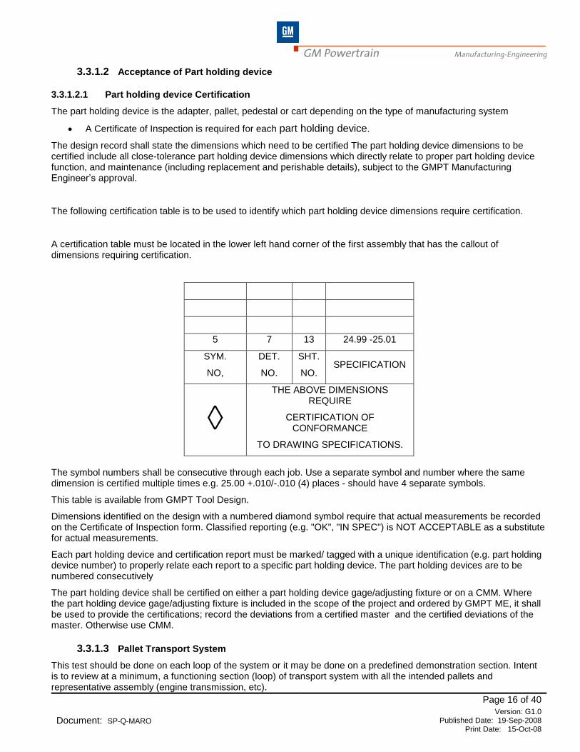
The following certification table is to be used to identify which part holding device dimensions require certification.
A certification table must be located in the lower left hand corner of the first assembly that has the callout of dimensions requiring certification.
5 7 13 24.99 -25.01
SYM.
NO,
DET.
NO.
SHT.
NO. SPECIFICATION
◊ THE ABOVE DIMENSIONS
REQUIRE
CERTIFICATION OF CONFORMANCE
TO DRAWING SPECIFICATIONS.
The symbol numbers shall be consecutive through each job. Use a separate symbol and number where the same dimension is certified multiple times e.g. 25.00 +.010/-.010 (4) places - should have 4 separate symbols.
This table is available from GMPT Tool Design.
Dimensions identified on the design with a numbered diamond symbol require that actual measurements be recorded on the Certificate of Inspection form. Classified reporting (e.g. "OK", "IN SPEC") is NOT ACCEPTABLE as a substitute for actual measurements.
Each part holding device and certification report must be marked/ tagged with a unique identification (e.g. part holding device number) to properly relate each report to a specific part holding device. The part holding devices are to be numbered consecutively
The part holding device shall be certified on either a part holding device gage/adjusting fixture or on a CMM. Where the part holding device gage/adjusting fixture is included in the scope of the project and ordered by GMPT ME, it shall be used to provide the certifications; record the deviations from a certified master and the certified deviations of the master. Otherwise use CMM.
3.3.1.3 Pallet Transport System
This test should be done on each loop of the system or it may be done on a predefined demonstration section. Intent is to review at a minimum, a functioning section (loop) of transport system with all the intended pallets and representative assembly (engine transmission, etc).
GM Powertrain Manufacturing-Engineering
Page 17 of 40
Document: SP-Q-MARO Version: G1.0
Published Date: 19-Sep-2008 Print Date: 15-Oct-08
This includes a minimum of:
· One complete section of transport system
· Include Control and Stops
· Content of this section should be defined in the request for quotation and confirmed during run-off planning (Reference Section 3.2) or during Design Review between GMPT ME and Supplier.
· This test must run for a minimum of 8 hours and for assembly systems shall include a minimum of 850 cycles
· All demands according to inquiry specifications have to be included in this tryout pilot section (e.g.: PC, ergonomics, operator interface buttons, etc.).
Runoff of this section has to be done with pre accepted pallets loaded with parts/assemblies. If there is not an adequate supply of representative parts for all the part holding devices, the remaining transport device are to be loaded with a weight which would simulate the weight of actual parts.. (See Section 3.3.1.2)
3.3.2 Capability Run
3.3.2.1 Requirements
· Machine has to be warmed up to its steady state operating conditions; these conditions should be agreed to before the pre-acceptance and documented during the run.
· For the capability run, the machine has to be set to its quoted operating parameters.
· The parts must be uniquely identified and the machine sequence recorded.
· The run should be continuous. Depending upon the interruption, the study may be continued or restarted. The decision to restart or continue the run is the responsibility of the Lead GMPT ME. The problem that caused the interruption must be found, corrected and recorded.
3.3.2.2 Run Size for Machining and Assembly Systems
If a machine consists of a number of identical stations, each station has to be treated independently. The parts have to be marked so that they can clearly be allocated to a machine, clamping points and machine spindle for both preliminary and final acceptance run. In Machining, with pallet machines, a larger sample size from a couple of pallets and a smaller sample size from the rest of the pallets may be acceptable. These decisions will impact the number of parts to be run and the selection of the part for inspection. Subject to this condition, at least 50 consecutively produced parts are required for the evaluation. Alternate method in section 3.4.3.8 shall be used for parallel machining centers.
Where sufficient parts are available, the sample run should consist of 50 consecutively produced parts. If the system has 50 or more pallets this run shall be conducted on 50 different pallets. If the system has less than 50 pallets use all the pallets. For assembly systems, the sample should be distributed across the pallets/pedestals available at runoff and treated as one population.
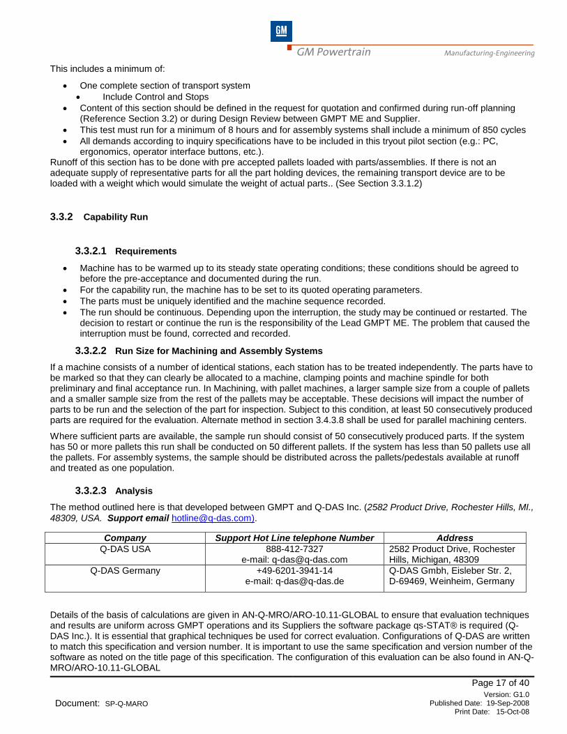
3.3.2.3 Analysis
The method outlined here is that developed between GMPT and Q-DAS Inc. (2582 Product Drive, Rochester Hills, MI.,
48309, USA. Support email [email protected]).
Company Support Hot Line telephone Number Address
Q-DAS USA 888-412-7327 e-mail: [email protected]
2582 Product Drive, Rochester Hills, Michigan, 48309
Q-DAS Germany +49-6201-3941-14 e-mail: [email protected]
Q-DAS Gmbh, Eisleber Str. 2, D-69469, Weinheim, Germany
Details of the basis of calculations are given in AN-Q-MRO/ARO-10.11-GLOBAL to ensure that evaluation techniques and results are uniform across GMPT operations and its Suppliers the software package qs-STAT® is required (Q-DAS Inc.). It is essential that graphical techniques be used for correct evaluation. Configurations of Q-DAS are written to match this specification and version number. It is important to use the same specification and version number of the software as noted on the title page of this specification. The configuration of this evaluation can be also found in AN-Q-MRO/ARO-10.11-GLOBAL

GM Powertrain Manufacturing-Engineering
Page 18 of 40
Document: SP-Q-MARO Version: G1.0
Published Date: 19-Sep-2008 Print Date: 15-Oct-08
All providers of computerized gages or measurement and test equipment are required to provide the data in the GMPT approved Q-DAS ASCII transfer format. Suppliers of such equipment shall provide a certification of their data format. It is each Supplier’s responsibility to contact Q-DAS Inc. directly for this certification. Engine Hot and Cold Test stands, Transmission, Valve Body and Pump Test stands are not required to output Q-DAS data. Where these devices do not output the Q-DAS format the equipment Supplier shall manually enter type 1a data into Q-DAS to conduct the evaluation.
3.3.2.4 Quality Acceptance Criteria
GMPT defines quality characteristics in three categories:
· Key Product Characteristics (KPC)
· Product Quality Characteristics (PQC)
· Standard Product Characteristics
· Documentation Required (DR) is a subset of Standard Prior to the delivery of the machine, investigations have to be carried out to check that the machine’s capability meets the required capability indices per Table below.
For all new part designs with new processes (new machine purchases), where KPC/PQC/DR characteristics are identified, the criteria from Table 3.3.2.4-1 shall be applied. For retooling and existing product designs, the criteria must be defined on a case-by-case basis.
The acceptance criteria can be broken down into the categories listed below:
· All characteristic values must be within specification (tolerance limits)
· No control chart violations
· Capability index should meet or exceed the requirement Table 3.3.2.4-1
· The special conditions (see chapter 3.4) must be evaluated to the requirements indicated in the specific paragraphs
· If attribute gages are used for capability run, capability my be demonstrated by using the appropriate percentage of tolerance Table 3.3.2.4-1
Type of Characteristic
Minimum Pp
Minimum Ppk
% of tolerance to use if checked by attribute gages
Key Product Characteristic 2.00 1.67 N/A
Product Quality Characteristic 2.00 1.67 75%
Standard Product Characteristic / DR 1.67 1.33 100%
Table 3.3.2.4-1 Capability index criteria
For retooling and existing product designs, criteria must be negotiated on a case-by-case basis, e.g. if a tolerance on an old design where current technology is not capable of meeting the criteria. In this case, ME & PE must either change the tolerance or change the Pp/Ppk requirements. In those cases where the criteria are not achieved, the Supplier has the responsibility to take appropriate steps to determine the cause and resolve.
3.3.2.5 Special Criteria for Smaller Sample
If parts are unavailable for the full capability run, the following tables shall be used to replace the acceptance criteria in Section 3.3.2.4

GM Powertrain Manufacturing-Engineering
Page 19 of 40
Document: SP-Q-MARO Version: G1.0
Published Date: 19-Sep-2008 Print Date: 15-Oct-08
Pp n 1.00 1.33 1.67 2.00
15 1.36 1.77 2.21 2.65 Minimum Pp, Ppk required for n < 50
20 1.23 1.61 2.01 2.41
25 1.15 1.52 1.90 2.27
30 1.10 1.46 1.82 2.18
40 1.04 1.38 1.72 2.06
> 50 1.00 1.33 1.67 2.00 Minimum Pp, Ppk required for n > 50
Ppk n 1.00 1.33 1.67 2.00
15 1.36 1.80 2.26 N/A Minimum Pp, Ppk required for n < 50
20 1.23 1.62 2.04 N/A
25 1.15 1.52 1.92 N/A
30 1.10 1.46 1.83 N/A
40 1.04 1.37 1.73 N/A
> 50 1.00 1.33 1.67 2.00 Minimum Pp, Ppk required for n > 50
Table 3.3.2.5-1 Small Sample Acceptance Criteria Note: Automatic evaluation of small sample sizes is available in qs-STAT versions 4.5 and later. This table shows the values for selected sample sizes; the automatic evaluation also looks at intermediate values and applies the appropriate indices. These values are based upon a confidence interval of 95%. Older versions of qs-STAT do not support this and manual evaluation of these indices is required. In this case, use the value of the sample size that is equal to or smaller than the actual sample size (e.g. for 33 pieces, use the values for 30).
3.3.3 Common-Sense Appraisal
The criteria given in 3.3.2.4 should not be treated as absolute. The GMPT Manufacturing Engineer has the ultimate responsibility for determining whether the process is acceptable or not. When analyzing the data, indications of rechecks, variation causes and so on may be noticed. Providing assignable causes are given and corrective action is or will be undertaken, equipment may be provisionally accepted. The detail of these assignable causes must be documented and approved by GMPT before equipment is approved for shipment. It is not in the scope of this document to describe how to analyze the data in this way but the following sections may be helpful.
3.3.3.1 “Out of specification” values
If “out of specification” values are recognized, then the respective parts have to be re-inspected in order to exclude potential measurement errors. If the original measurement was in error, the results of the second inspection shall replace the original inspection and be used in the analysis. If the second inspection results indicate the original inspection to be accurate, the original results shall be used in the analysis unless an assignable cause outside the control of the equipment manufacturer is identified. For example if analysis of the parts indicates porosity in a casting caused a part to show undersize or off location, the results from that part should be deleted from the analysis and make the evaluation on the remaining parts. Assignable causes that are within the control of the equipment manufacturer must be corrected and documented. It shall be the responsibility of the GMPT Manufacturing Engineer to determine if the study needs to be repeated. If no assignable cause is determined, the analysis must be conducted using all the data.

GM Powertrain Manufacturing-Engineering
Page 20 of 40
Document: SP-Q-MARO Version: G1.0
Published Date: 19-Sep-2008 Print Date: 15-Oct-08
3.3.3.2 Targeting Failure
3.3.3.2.1 Pre-Run
The Supplier shall target their machines prior to run-off. Where targeting other than to nominal is required, the Supplier shall identify these items during the design review and is responsible to determine the proper target value to assure machine function and capability. For the Preliminary Acceptance at the Suppliers facility, attention should be paid more to variation than to targeting. Where a targeting failure occurs, the decision to adjust the machine and re-run the study or to conditionally accept the study as is and wait to make the adjustment at the production facility shall be at the sole discretion of the GMPT lead ME responsible for the project. Where preliminary acceptance was conditional, notation is to be made on the acceptance report of those items which still need further corrections.
3.3.3.2.2 Capability Run
Where the process fails for the Process Capability Index (Ppk or Pok) but passes the Process Potential Index (Pp or Po) adjustments to targeting must be made and the study rerun. For Preliminary Acceptance at the Supplier facility only, the criteria for the Process Capability Index (Ppk or Pok) may be waived and a conditional acceptance made based on an analysis of the Process Potential Index (Pp or Po). This decision is at the sole discretion of the GMPT lead ME, based upon Engineering judgment that the particular characteristic is easily adjustable in the GMPT manufacturing facility. Where preliminary acceptance was conditional, notation is to be made on the acceptance report of those items which still need further corrections.
3.3.4 Report Generation
Evidence of this capability study should be submitted in the standard form (AN-Q-MRO/ARO-10.11-GLOBAL). The GMPT acceptance team and the equipment Supplier shall review these reports. These reports must include:
· Individual Characteristic Report.
· Characteristic Summary: (listing of characteristic capability indices, etc.)
Two copies of this report shall be provided to Manufacturing Engineering. One copy shall be maintained at the appropriate ME central (GMPT), the other copy shall be maintained at the production facility where the equipment is to be installed. In addition electronic media are to be provided to both organizations.
3.3.5 Cutting Tool-Change Capability
In order to ensure that tooling can be changed, without the process being adversely affected, the following is done: After the capability run, all the Cutting Tools on the machine are changed. Ten parts (5 min.) are machined and
inspected. Calculate the x from the capability run ( x 1) and the x from the tool change study ( x 2). All parts must be
within specification. See AN-Q-MRO/ARO-10.11-GLOBAL. – Tool Change Report. In the situation where the proper tool setting devices are not available, this study may be conducted by simulating a tool change. The simulated tool change requires the tools to be removed and then replaced in the same position they were removed from. If the simulated tool change is used for the Final Acceptance, this study should be re-run when the proper tool setting equipment is available. In this case, if a problem is found, an analysis shall be made to determine if there is a machine problem or a tool-setting problem. If it is determined to be a machine problem, the Supplier shall be responsible to make corrections.
Acceptance criteria:
%2521 xx of tolerance
Or
12 xTmxTm
Where Tm is the Tolerance middle for Bilateral Tolerances and Tm is the Natural Bounded Limit for Unilateral Tolerances For those features, which are checked with attribute gages, use the criteria from 3.3.2.4.
GM Powertrain Manufacturing-Engineering
Page 21 of 40
Document: SP-Q-MARO Version: G1.0
Published Date: 19-Sep-2008 Print Date: 15-Oct-08
The tool change capability study is not required for duplicate machines with identical tools product and process unless otherwise specified. This test shall only be conducted on the first set of machines where duplicate machines are purchased. One machine of each operation shall be tested. Where no tool change capability test is conducted, a functional tool change tests shall be conducted.
3.3.6 Important Note For Machine Delivery
The only person authorized to release the equipment for shipping is the MANUFACTURING ENGINEER responsible for the considered parts and machines. Pre Acceptance statement must be completed and signed to authorize equipment payment (see section 3.6).
3.3.7 Equipment Non-Conformance
All discrepancies must be recorded. These must be either:
· Identified, corrected and proven at the equipment Suppliers or
· Confirmed as protocol issues (i.e. those to be corrected on installation at production plant)
It may be necessary that the capability run be repeated to prove modifications and improvements to the equipment and/or process. In this instance, all previous conditions for the capability run and evaluation method apply.
3.4 SPECIAL CONDITIONS
3.4.1 General Note
If special conditions, which are not covered in section 3.4, are considered applicable, they ought to be in-line with the spirit of this specification. The conditions will be agreed upon between GMPT Manufacturing Engineering Department and the equipment Supplier prior to final order placement.
3.4.2 Special Characteristics Conditions
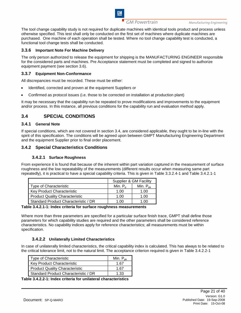
3.4.2.1 Surface Roughness
From experience it is found that because of the inherent within part variation captured in the measurement of surface roughness and the low repeatability of the measurements (different results occur when measuring same part repeatedly), it is practical to have a special capability criteria. This is given in Table 3.3.2.4-1 and Table 3.4.2.1-1
Supplier & GM Facility
Type of Characteristic Min. Pp Min. Ppk
Key Product Characteristic 1.00 1.00
Product Quality Characteristic 1.00 1.00
Standard Product Characteristic / DR 1.00 1.00
Table 3.4.2.1-1: Index criteria for surface roughness measurements Where more than three parameters are specified for a particular surface finish trace, GMPT shall define those parameters for which capability studies are required and the other parameters shall be considered reference characteristics. No capability indices apply for reference characteristics; all measurements must be within specification.
3.4.2.2 Unilaterally Limited Characteristics
In case of unilaterally limited characteristics, the critical capability index is calculated. This has always to be related to the critical tolerance limit, not to the natural limit. The acceptance criterion required is given in Table 3.4.2.2-1
Type of Characteristic Min. Ppk
Key Product Characteristic 1.67
Product Quality Characteristic 1.67
Standard Product Characteristic / DR 1.33
Table 3.4.2.2-1: Index criteria for unilateral characteristics
GM Powertrain Manufacturing-Engineering
Page 22 of 40
Document: SP-Q-MARO Version: G1.0
Published Date: 19-Sep-2008 Print Date: 15-Oct-08
For retooling and existing product designs, criteria must be negotiated on a case-by-case basis. For example if a tolerance on an old design where current technology is not capable of meeting the criteria. In this case, ME & PE must either change the tolerance or change the Ppk requirements. In those cases where the criteria are not achieved, the Supplier has the responsibility to take appropriate steps to determine the cause and resolve.
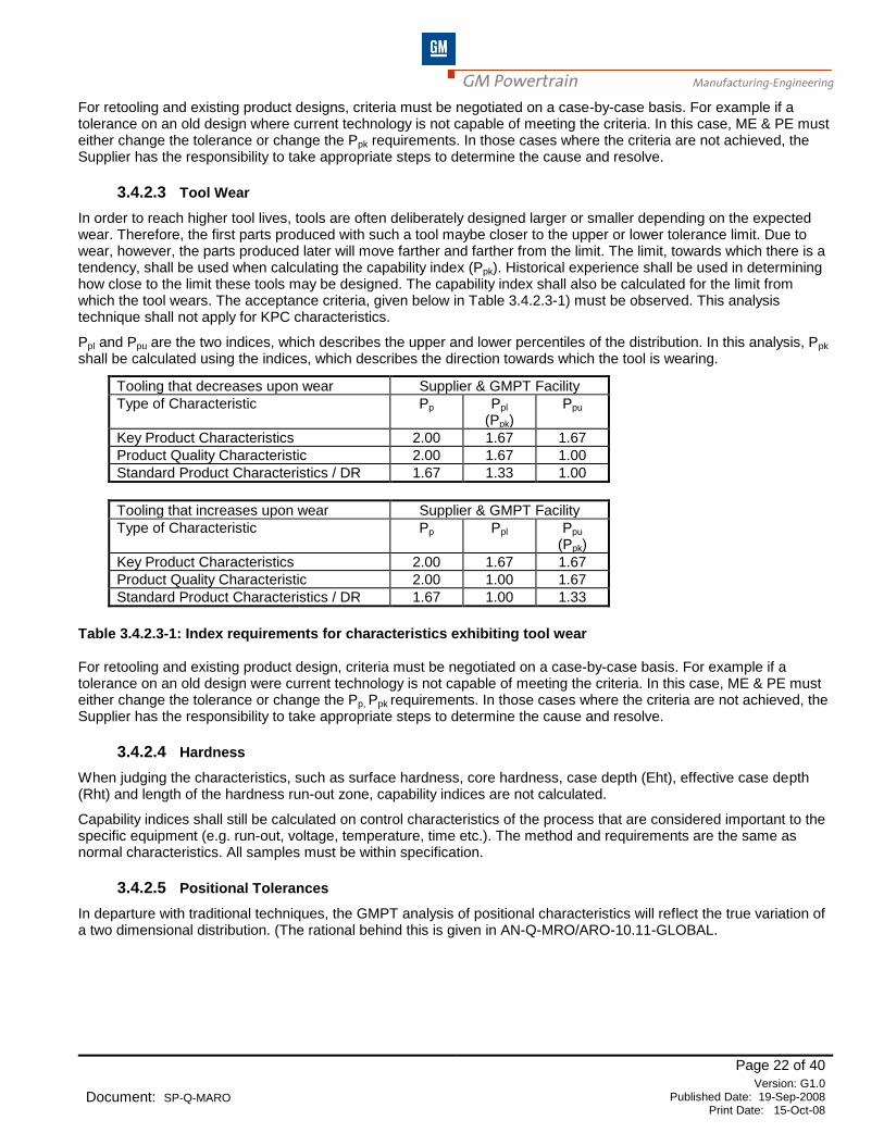
3.4.2.3 Tool Wear
In order to reach higher tool lives, tools are often deliberately designed larger or smaller depending on the expected wear. Therefore, the first parts produced with such a tool maybe closer to the upper or lower tolerance limit. Due to wear, however, the parts produced later will move farther and farther from the limit. The limit, towards which there is a tendency, shall be used when calculating the capability index (Ppk). Historical experience shall be used in determining how close to the limit these tools may be designed. The capability index shall also be calculated for the limit from which the tool wears. The acceptance criteria, given below in Table 3.4.2.3-1) must be observed. This analysis technique shall not apply for KPC characteristics.
Ppl and Ppu are the two indices, which describes the upper and lower percentiles of the distribution. In this analysis, Ppk shall be calculated using the indices, which describes the direction towards which the tool is wearing.
Tooling that decreases upon wear Supplier & GMPT Facility
Type of Characteristic Pp Ppl (Ppk)
Ppu
Key Product Characteristics 2.00 1.67 1.67
Product Quality Characteristic 2.00 1.67 1.00
Standard Product Characteristics / DR 1.67 1.33 1.00
Tooling that increases upon wear Supplier & GMPT Facility
Type of Characteristic Pp Ppl
Ppu
(Ppk)
Key Product Characteristics 2.00 1.67 1.67
Product Quality Characteristic 2.00 1.00 1.67
Standard Product Characteristics / DR 1.67 1.00 1.33
Table 3.4.2.3-1: Index requirements for characteristics exhibiting tool wear For retooling and existing product design, criteria must be negotiated on a case-by-case basis. For example if a tolerance on an old design were current technology is not capable of meeting the criteria. In this case, ME & PE must either change the tolerance or change the Pp, Ppk requirements. In those cases where the criteria are not achieved, the Supplier has the responsibility to take appropriate steps to determine the cause and resolve.
3.4.2.4 Hardness
When judging the characteristics, such as surface hardness, core hardness, case depth (Eht), effective case depth (Rht) and length of the hardness run-out zone, capability indices are not calculated.
Capability indices shall still be calculated on control characteristics of the process that are considered important to the specific equipment (e.g. run-out, voltage, temperature, time etc.). The method and requirements are the same as normal characteristics. All samples must be within specification.
3.4.2.5 Positional Tolerances
In departure with traditional techniques, the GMPT analysis of positional characteristics will reflect the true variation of a two dimensional distribution. (The rational behind this is given in AN-Q-MRO/ARO-10.11-GLOBAL.

GM Powertrain Manufacturing-Engineering
Page 23 of 40
Document: SP-Q-MARO Version: G1.0
Published Date: 19-Sep-2008 Print Date: 15-Oct-08
For correct evaluation of these characteristics, qs-STAT® software shall be used. In summary:
· The study of a positional feature must include data collection from both of the perpendicular axes to the axis of the feature,
· The consideration of a positional tolerance as a rectangular area is not allowed and
· Special capability indices are calculated: Po/Pok (equivalent to Pp/Ppk in general terms).
The study philosophy shall be that used for normal characteristics. However, the criteria for acceptance shall be that listed below and given in Table 3.4.2.5-1
· The data from the two axes shall be studies for stability.
· Scatter chart (see AN-Q-MRO/ARO-10.11-GLOBAL) is used to determine if all parts are in specification,
· Data point grouping should be examined for segmentation or anomalies.
Supplier & GMPT Facility
Type of Characteristic Min. Po Min. Pok
Key Product Characteristic 2.00 1.67
Product Quality Characteristic 2.00 1.67
Standard Product Characteristic / DR 1.67 1.33
Table 3.4.2.5-1 : Minimum Po/Pok requirements For retooling and existing product designs, criteria must be negotiated on a case-by-case basis. For example if a tolerance on an old design where current technology is not capable of meeting the criteria. In this case, ME & PE must either change the tolerance or change the Po/Pok requirements. In those cases where the criteria are not achieved, the Supplier has the responsibility to take appropriate steps to determine the cause and resolve.
3.4.3 Special Process Conditions - Machining
3.4.3.1 Gears and Splines (Including those on Shafts)
3.4.3.1.1 Manual transmission
There are particular requirements to analyze gear characteristics as follows:
· Measurement over two balls and concentricity must be carried out in according with the standard methodology MARO complying with Table 3.3.2.4-1.
For Involute, Total Pitch Error and Lead there shall be no capability indices applied. Instead, 5 pieces (minimum) shall be inspected as follows:
The average values out of 4 teeth from each piece must be within 90% of the entire tolerance. The measurement of every single tooth must be within 100% of the entire tolerance. The total pitch error Fp must be within 90% of the entire tolerance.
3.4.3.1.2 Automatic Transmission Gears
3.4.3.1.2.1 General Guidelines
Certain primary gear tooth characteristics are to be treated as standard product characteristics and are to be evaluated in accordance with the applicable process capability indices listed in tables 3.3.2.4-1, 3.4.2.2-1, or 3.4.2.3-1.
These primary characteristics are: Size deviations
· Tip Diameter (da)
· Root Diameter (df)
· Diameter over (between) balls or pins (Md)
GM Powertrain Manufacturing-Engineering
Page 24 of 40
Document: SP-Q-MARO Version: G1.0
Published Date: 19-Sep-2008 Print Date: 15-Oct-08
Profile deviations
· Mean Profile Slope Deviation (f)
· Profile Slope Variation (f)
· Mean Profile Barreling (C)
Helix deviations
· Mean Helix Slope Deviation (fβ)
· Helix Slope Variation (fβv)
· Mean Helix Crowning (Cβ)
Radial composite deviations
· Runout by Composite Test
· Eccentricity (f)
· Circularity
Characteristics not listed above as primary are to be considered secondary characteristics (e.g., form deviation, mean tooth-to-tooth radial composite deviation, nicks, undulations, etc). For these secondary characteristics, there shall be no capability indices applied. Instead, secondary characteristics shall be inspected as follows:
For all samples evaluated during the capability run, the measured values must be within 90% of the entire tolerance.
3.4.3.1.2.2 Special Provisions
Based on certain operations, it may be necessary to preclude some features from the primary and / or secondary characteristics above. Conversely, some operations may require the addition of critical features to the primary characteristic list. Whether the characteristic list is added to or subtracted from, it is critical to have a defined list of characteristics, expectations, runoff plans, gage plan, etc. as outlined in section 3.2.
3.4.3.2 Deep-Fillet-Rolling and Roll-Straightening
For the evaluation of characteristics on parts subject to deep-fillet-rolling, there is no calculation of capability indices. The proof of capability is established based on capability indices related to those process parameters influencing the rolling process.
3.4.3.2.1 Prerequisite
· The investigation must be separately performed and analyzed for each type of part, part type and raw part Supplier.
· The rolling force, roller radii and the tool angle must be verified per part print.
· Tolerance of the rolling force is per part print, (where unspecified use +/- 5%).
· Roll-straightening forces are different than rolling forces. All straightening forces must be within 100% of the Part Print specifications for straightening force (no capability indices are calculated on roll-straightening force).
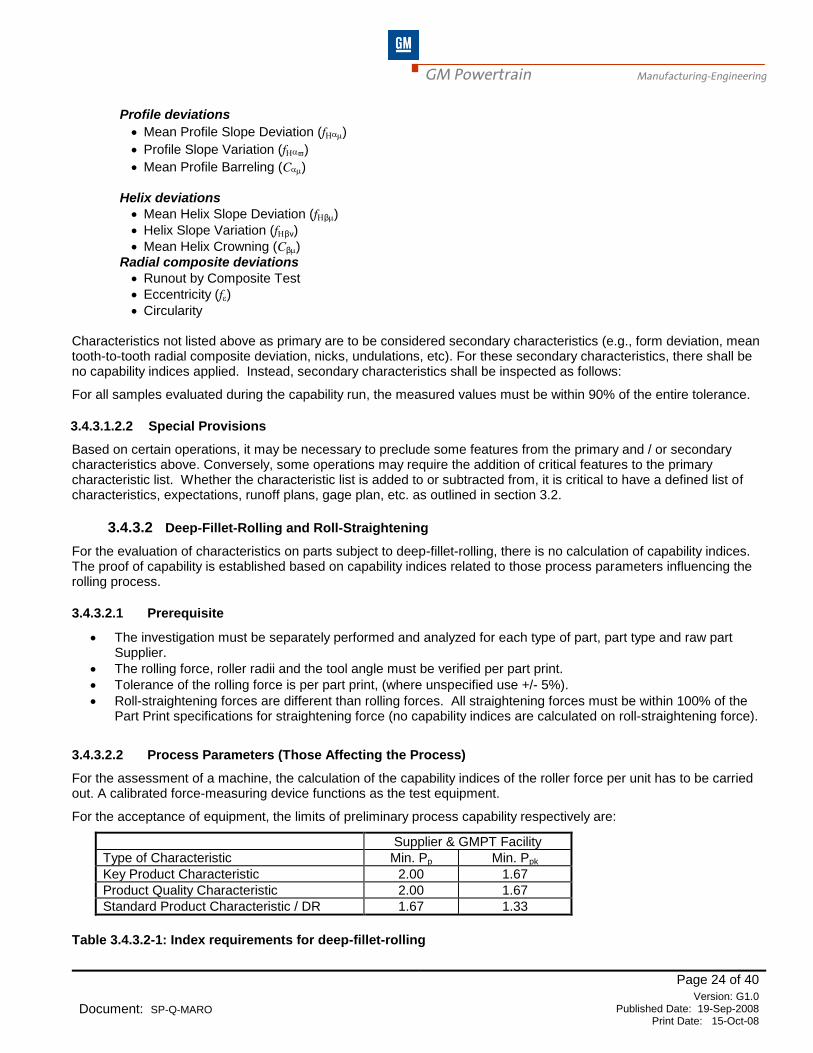
3.4.3.2.2 Process Parameters (Those Affecting the Process)
For the assessment of a machine, the calculation of the capability indices of the roller force per unit has to be carried out. A calibrated force-measuring device functions as the test equipment.
For the acceptance of equipment, the limits of preliminary process capability respectively are:
Supplier & GMPT Facility
Type of Characteristic Min. Pp Min. Ppk
Key Product Characteristic 2.00 1.67
Product Quality Characteristic 2.00 1.67
Standard Product Characteristic / DR 1.67 1.33
Table 3.4.3.2-1: Index requirements for deep-fillet-rolling

GM Powertrain Manufacturing-Engineering
Page 25 of 40
Document: SP-Q-MARO Version: G1.0
Published Date: 19-Sep-2008 Print Date: 15-Oct-08
For retooling and existing product designs, criteria must be negotiated on a case-by-case basis. For example if a tolerance on an old design where current technology is not capable of meeting the criteria. In this case, ME & PE must either change the tolerance or change the Pp/Ppk requirements. In those cases where the criteria are not achieved, the Supplier has the responsibility to take appropriate steps to determine the cause and resolve.
3.4.3.2.3 Radial Runout (Characteristic Effected By the Process)
Radial runout, externally measured between axial centers, shall demonstrate all values within tolerance. Manufacturing Engineering must define the tolerance.
3.4.3.2.4 Additional Resultant Parameters
In order to check process quality and integrity it is best practice to also study these factors:
· Tool angle
· Run out tests
· Total part length
Also, additional measurements on a limited number of crankshafts shall be performed (due to the difficulty, expense and logistics of inspection).
Using ten crankshafts the following analysis shall be performed: Before and after rolling, measurements are made at top & bottom of the con-rod bearings and at pre-selected points on the main bearings (at same point prior to and after rolling). The analysis is related to the difference of these dimensions before and after the process. Features shall demonstrate all values within in-process tolerance.
Using two crankshafts the following analysis shall be performed: Check the penetration depth of the rolling tool by studying the formed profile. The radii should to be measured with impression prints (M50: 1) or optical measuring equipment. The values prior to and after rolling have to be compared and analyzed.
3.4.3.3 100% Automatic Gaging
Automatic Tool Compensated Processes:
As these processes are not normal distributions and are controlled by the gage, no capability indices are required. Use the criteria below. All samples from the capability run are inspected.
In Process Controlling Gages and Post Process Gages:
In particular cases identified by GMPT, the capability indices requirement, may be waived, for processes which are followed immediately by 100% inline gages. All samples from the capability run shall be inspected.
In these cases the machine capability is proven if all values:
a.) Of bilateral characteristics are within 80% of the drawing tolerance and
b.) Of unilateral characteristics are within 90% of the drawing tolerance towards the critical tolerance limit.
See Appendix for formulas
There are no capability indices calculated.
This applies also to KPC / PQC characteristics.
b)
80 %
10 % 10 %
USG OSG 90 %
Critic. tolerance
a)

GM Powertrain Manufacturing-Engineering
Page 26 of 40
Document: SP-Q-MARO Version: G1.0
Published Date: 19-Sep-2008 Print Date: 15-Oct-08
3.4.3.4 Modifications / Relocations
3.4.3.4.1 Procedure to be observed before placing an order for manufacturing equipment to be modified or
relocated respectively:
· Prior to placing an order, the actual conditions of the manufacturing equipment are to be recorded concerning the characteristics to be accepted.
· These characteristics are to be determined by PT ME, the PT plant and the Supplier.
· A process capability analysis is to be made by PT plant per GQR-016.
· For relocation of manufacturing equipment, the PT plant is responsible for necessary overhaul activities.
· Information gathered by the maintenance department concerning failures and measures initiated are to be presented together with long-term quality records. This information shall serve as a basis for placing the order.
3.4.3.4.2 Procedure to be adhered to before the Modification / Relocation:
· Max. four weeks before the modification or relocation, the actual conditions of the machine are again to be recorded and characteristics to be defined for the acceptance.
· Any measures carried out by the maintenance department in the meantime between the order placing and the modification or relocation are to be disclosed by the PT plant.
· If there are differences in the actual condition at this time from the actual conditions recorded before placing the order, the plant is responsible for repairing the machine to the condition recorded before the order.
3.4.3.4.3 Procedure to be followed after the Modification or Relocation:
3.4.3.4.3.1 Rough and Semi-Finish Operations:
· In case of Rough and Semi-Finish operations, the one-part and five-part Pre-Runs are not evaluated. In accordance with the 25% tolerance range. Instead, a 90% utilization of the tolerance is permitted, relative to the Process Tolerance.
· The minimum capability indices to be adhered to are the capability values of the actual conditions prevailing prior to the modification or relocation.
3.4.3.4.3.2 Finishing Operations:
· For major overhauls and complete retooling projects, the requirements are the same as those defined in MARO for new machines.
· For minor overhauls and relocations, as a minimum the machine must demonstrate capability indices that meet or exceed those prior to the overhaul or relocation.
In the case of Parallel Machining Operations, the evaluation is to be conducted as per Section 3.5.2.2.2.2. Method B except a 30-piece capability study may be used. The capability indices are to be evaluated through qs-STAT in accordance with the criteria established in the MARO Table 3.3.2.4-1
3.4.3.5 Introduction of Additional Parts
3.4.3.5.1 Within a Part Family
Where the features are produced with the same equipment and process and are the same or similar to those already qualified and in production, no capability study is required for MARO. Capability shall be demonstrated by the part handling test and a 5 pc run. The results of the 5 piece run for the new part are added to the results of the capability data for the existing part. If the capability indices of the combined data still meet the criteria (3.3.2.4) and there are no control limit violations, the study is acceptable. If not, make adjustments and repeat or conduct a full 50 pc capability study.

GM Powertrain Manufacturing-Engineering
Page 27 of 40
Document: SP-Q-MARO Version: G1.0
Published Date: 19-Sep-2008 Print Date: 15-Oct-08
Where the features or equipment are new (tooling, fixtures and or datums different), those features, which are either new or produced with new equipment, shall be held to the full MARO requirements.
In addition verification of error proofing for type identification must be demonstrated at both load and unload devices as appropriate.
3.4.3.5.2 Different Part Family
Within the same equipment, only for different characteristics the capability study shall be held to the full MARO requirements.
3.4.3.6 Quality Evaluation of Shot Peening
3.4.3.6.1 Purpose:
This guideline shall serve to evaluate the quality of the following shot Peening processes:
· Compressed air blasting
· Impeller shot Peening
3.4.3.6.2 Pre Acceptance and Final Acceptance:
3.4.3.6.2.1 Pre Conditions
Before the date of preliminary acceptance test, the machine Supplier has to confirm the following in writing to GMPT Manufacturing Engineering Department:
· The machine has passed an endurance run– Section 3.2.2.1
· Machine complies with all pertinent specifications required in the purchase order:
· Safety, sound levels, hazardous materials, coolant, hydraulics, pneumatics, lubrication, mechanical, automation, electrical controls, etc.
3.4.3.6.2.2 Run 3 Pieces per fixture and verify to the drawing specification
· Almen values
· Degree of coverage
· Residual stress
3.4.3.6.2.3 Preliminary acceptance at the Supplier’s Plant:
Prior to the acceptance test, the Almen values are to be checked from each station and verified to be within specification.
50 parts (or 25 parts each station) are to be produced consecutively. 2 pieces from each station are sampled near the beginning and near the end of the run. These pieces are
measured and documented for:
· Degree of coverage Residual stress If the achieved results correspond to the drawing specifications, and all preconditions were met, the approval
for the delivery of the machines will be granted.
3.4.3.6.2.4 Evaluation:
Capability indices shall not be calculated. The values obtained from the samples shall completely be in accordance with the drawing specification. The results are to be recorded and passed on to GMPT ME for the purpose of documentation.
3.4.3.7 Tool Change and Multiple process streams within a Run
When calculating capability indices for extended runs or for ongoing production, particularly where tool changes are
encountered during the study, and the Mixed Distribution is found, the Intrinsic Capability indices Cpi and Cpki shall ill
be used. See AN-Q-MRO/ARO-10.11-GLOBAL

GM Powertrain Manufacturing-Engineering
Page 28 of 40
Document: SP-Q-MARO Version: G1.0
Published Date: 19-Sep-2008 Print Date: 15-Oct-08
Supplier & GMPT Facility
Type of Characteristic Min. Cpi Min. Cpki
Key Product Characteristic 2.00 1.67
Product Quality Characteristic 2.00 1.67
Standard Product Characteristic / DR 1.67 1.33
Table 3.4.3.7-1 Minimum Cpi /Cpki requirements
The indices Cpi and Cpki are only for extended runs or ongoing production.
3.4.3.8 Acceptance of Lean Agile Flex. Machining Centers
3.4.3.8.1 Preliminary Acceptance of Parallel Operation (At Supplier)
3.4.3.8.1.1 Acceptance of First Machine
Conduct the preparation as explained in section Table 3.3.2.4-1 Capability index criteria. To evaluate the first machine, calculate the capability indices by using 50 parts (if there are 2 clamping stations, 25 parts for each station and part type). For acceptance, the minimum criteria for the process capability are shown in Table 3.3.2.4-1
The following additional evaluations have to be carried out:
· Geometrical acceptance with standard machining test (e.g. pallet and stone cube or circle, diamond, square test)
· Dynamic measurement by quick check
· Machining of simple master part including measurement report (Ref: VDI/DGQ 3441)
· Functional evaluation of clamping fixture and measuring with report.
· Cycle time verification of tool changer and pallet swapper where so equipped.
As part of the acceptance of the first machine; the range of tolerance has to be established by the machine Supplier as a reference for later machines. Details of the specific test shall be agreed to by GMPT and the Supplier during the run-off planning (section 3.2).
· A short check program may be used for the capability study. The 1 pc run and the 5 piece run would check all characteristics. The process capability run would check the first and the last feature of a feature group (or two selected features at the extremes of the part if the first and last features are adjacent to each other). The feature group is identical features produced by the same spindle and the same tool. If the feature group is produced by more than one spindle or tool, two features from each tool and each spindle must be inspected. Where the same tool is used on multiple faces, at least two features from each face must be selected. This short check program would be used for standard care features only; it would not be used for PQC’s and KPC’s. This short check program would also be used for the tool change study and the cold start study.
3.4.3.8.1.2 Acceptance Of The Succeeding Machines
Succeeded Machines are accepted by using Dry Acceptance Test, the Supplier has to deliver:
· Geometrical acceptance with standard machining test (e.g. pallet and stone cube or circle, diamond, square test)
· Dynamic measurement by quick check
· Machining of simple master part including measurement report (Ref: VDI/DGQ 3441)
· Functional evaluation of clamping fixture and measuring with report.
· Cycle time verification of tool changer and pallet swapper where so equipped.
3.4.3.8.1.3 Serial and parallel Process
For such a system the complete loop will be accepted after the last operation of the loop.
For duplicate or parallel lines use dry acceptance (see sections 3.4.3.8.1.1 and 3.4.3.8.1.2)

GM Powertrain Manufacturing-Engineering
Page 29 of 40
Document: SP-Q-MARO Version: G1.0
Published Date: 19-Sep-2008 Print Date: 15-Oct-08
3.4.3.9 Acceptance of Adapter Plates Processes
· Gage station checks (where available)for hand gages on adapter
· In process checks between cells using same adapter - CMM checks on adapter
· For the last operation off each adapter type, the CMM checks are without adapter. If this is an in process check and access to the locators is available on the adapter it shall be checked with the adapter. All end of line CMM checks shall be without adapter.
· Where checks are done on adapter plate 5 pc study is made comparing the values of each part with and without adapter to less than 10% of the Process tolerance (or product tolerance if no process tolerance specified)
3.4.3.10 Balancing Machines
Balancing machines shall be evaluated as other machines, however they must first be tested as gages (see MSS). As the data is bivariate, the indices Po and Pok shall be used for the evaluation (see section 3.4.2.5). The mass/angle data shall be converted to X/Y data for the purpose of this evaluation. All other aspects of the evaluation apply (section 1.1.3). Acceptance criteria are the same as in Table 3.3.2.4-1 Capability index criteria and Table 3.3.2.5-1 Small Sample Acceptance Criteria
3.4.3.11 Straightening Machine
Conduct an analysis of the measurement system per MSS Type 1 and Type 3 studies. Particular care should be taken relative to marking gear teeth or part orientation so that the measurements can be repeated accurately.
As this process contains an integral 100% inspection device, see sect 3.4.3.3 for acceptance criteria.
3.4.3.12 Part Cleaning Machine
In general the procedure for Acceptance of Cleaning Machines (Washers) is similar to that used for other machines but with some differences. The following items must be completed:
3.4.3.12.1 Equipment pre-qualification
Same as sect 3.3.1 except the 1 and 5 part runs are replaced with a 1 part run within 50% of the cleanliness specification. See Regional specs for measurement techniques to determine residual dirt on component parts
Regional 2: (E, NA) Section 3.4.3.12.1 Equipment pre-qualification
GME 7061 or GME 60225- Determination of residual dirt on finished engine and gear components
E
GMPT NA Engineering Standards - procedure #GMN6752 and GQR-050 NA
3.4.3.12.2 Nozzle Alignment Test
Each hole or cavity is packed with high temperature grease and the machine is cycled thru the stations that have targeted wash or dry. This is done to confirm nozzle alignment. The machine must remove the high temperature grease from all the holes/cavities with Normal temperature fluid. In the case where the normal temperature fluid would melt the grease then the test must be performed with fluid that is under the melting temperature of the grease. This test should be conducted separately for Air and Liquid Nozzles.
3.4.3.12.3 Preliminary Acceptance Run
Run a 50 piece study, sample 10 pieces minimum from the study. The capability requirement is met if all values are less than 67% of spec. here the machine’s automatic load mechanism is unavailable at runoff, sample 10 pieces from a 25 piece run. This evaluation is a manual evaluation; no Q-DAS report is used.
· Part preparation – parts may be pre-cleaned to remove any packaging or preservative materials used during shipment to the washer Supplier. The parts should be artificially contaminated in every cavity/feature with representative chips as expected from the worst-case production process. Parts should be prepared to represent the production process as expected for the incoming material.

GM Powertrain Manufacturing-Engineering
Page 30 of 40
Document: SP-Q-MARO Version: G1.0
Published Date: 19-Sep-2008 Print Date: 15-Oct-08
· During the capability run use the same fluid, concentration, temperature, cycle time and pressure which will be used in the GMPT plant.
· Characteristics to be evaluated
· Temp – within 100% of specification
· Cleanliness Maximum 67% of Specification
· Cycle Time within 100% of specification
· Dryness Subjective evaluation using:
· Visual - no puddles no dampness
· Blotter – no moisture transferred to blotter
· Drips - 1 minute minimum drip time on each surface – no drips on clean paper towel
3.4.3.12.3.1 CMM Washers
Same as above, only 5 pieces are measured. Cleanliness is evaluated both subjectively and quantitatively. The part must be dry with no visible chips. The 5 piece sample is tested for cleanliness to the following criteria. The total contamination in each part must be less than 100 milligrams mass with no particle larger than 25 microns. Up to 100% of this tolerance is allowable
3.4.3.13 Welding Machines
Quality Assessment of Welding Processes - This regulation applies to electron beam and laser beam welding to assess the quality of the welding processes.
3.4.3.13.1 Preparation
The acceptance of the test equipment shall be done by MSS Type 1 Study. Furthermore an error proofing test of the three different conditions of the weld seam shall be conducted:
· OK Welded Parts
· Not Welded parts
· Tack Welded Parts
Test equipment must be capable of recognizing improperly welded parts. It must accept condition 1 and reject conditions 2 and 3 above.
Parts must be clean and dry.
3.4.3.13.2 Preliminary Acceptance Tests:
5 parts are taken from a 50 parts run.
Every tenth part is cut, resulting in a cross section, and the corresponding micrograph of the metallographic specimen verified for the correct depth of the welded seam. Must be done in two sections including both the beginning zone and the finish zone.
3.4.3.13.3 Evaluation:
· The treated samples are measured by means of a magnifier and the values shall be within 100% of the tolerance.
· When evaluating welded connections, capability indices are not calculated.
· A 100% opto-electronic examination is made regarding
the position of the welded seam and
the upper weld bead.
· Specified welding depth:
GM Powertrain Manufacturing-Engineering
Page 31 of 40
Document: SP-Q-MARO Version: G1.0
Published Date: 19-Sep-2008 Print Date: 15-Oct-08
The specified welding depth is influenced by the subsequently stated process parameters:
· power input for welding
· speed (advance rate) as verified and measured by welding time
Regarding these parameters, capability indices are to be calculated under consideration of the same methods and requirements as are applicable to normal characteristics.
Before the order is placed, PT ME, PT plants and the machine Supplier jointly determine tolerance limits of the mentioned process parameters.
The results are to be recorded and passed on to GMPT ME for documentation.
3.4.4 Special Process Conditions - Assembly
3.4.4.1 Defining the Performance Parameters
Evaluation of the equipment performance (if possible with PPAP-parts) at the Supplier’s facility is carried out on the basis of the following tests:
Cycle Time: Compliance with required equipment cycle time shall be demonstrated. For acceptance by the Production Plant, the basis for performance evaluation is a demonstration of the entire system including quality and throughput. The run may be the PPAP run, or other pre-production system try out. Cycle time and Throughput of the assembly line have to be proved and documented.
3.4.4.2 Process-related Testing
Process–Related Functional Test:
To evaluate process performance, a functional test (if available using Original-PPAP-parts) has to be performed.
The test should use 50 parts minimum (or be on process-related scale, respectively). By the use of these parts and according to the individual assembly process.
· Process capability is to be proved as per section 3.3.2.4 or
· For assembly processes where capability evaluation is not possible, processes have to be proved through subjective evaluation by a responsible person from GMPT ME and documented in the acceptance report.
3.4.4.3 Feeding and Positioning of Assembly Parts
· The performance of a feeder unit shall be proven by means of a functional test with parts for 8 hours of trouble free operation (Minimum 850 Cycles).
· The functional test of the parts handling equipment (positioning) shall be agreed with the Supplier for specific process procedures during the Design Review (or during the Runoff planning).
· The results obtained are to be documented and reported to GMPT ME prior to the system acceptance.
· To evaluate process reliability and throughput, a sufficient number of original parts (if possible PPAP-parts) must be available for filling the feeder unit.
3.4.4.4 Lift Assists - Part Handling Devices
For acceptance of any lift assists SP-M-Lift Assists shall be used.
3.4.4.5 Process Capability of Pressing and Joining Operations
Prerequisites
For evaluation of the process a sufficient number of original parts (if possible PPAP-parts) for loading the feeder unit (feeder conveyor) must be available.
The test parameters, force of pressure (min; max), force of joining (min; max), length of projection period etc have to be defined based on product requirements.
GM Powertrain Manufacturing-Engineering
Page 32 of 40
Document: SP-Q-MARO Version: G1.0
Published Date: 19-Sep-2008 Print Date: 15-Oct-08
Proof Of Capability
Equipment capability to demonstrate the ability to accurately measure force and distance shall be tested according to Type 1 and Type 1a Procedure (SP-Q-MSS); evaluation of 50 cycles without parts. For process evaluation, the capability indices Pp / Ppk of the above characteristics have to be determined, using minimum 50 parts (or process-related scale) and included in the acceptance report.
Where the pressing equipment is monitoring a process, no capability indices are calculated; where it is a controlling operation (e.g. Press to distance) Capability indices shall be demonstrated per Table 3.3.2.4-1 Capability index criteria
3.4.4.6 Process Capability for Dispensing Equipment, Lubricating (Oil) Filling and Liquid Sealant
Application
8-hr functional test run without medium; result to be included in the acceptance report (See Section3.2.2.1)For processes requiring a proof of capability where product is toleranced for quantity, conduct a mini process capability (minimum of 10 cycles). See Table 3.3.2.4-1 Capability index criteria and Table 3.3.2.4-1 Capability index criteria
A sufficient quantity of the medium according to approved GMPT PE specification has to be made available. Assessment shall be made based on weight, volume or level depending on Product Specification.
The quantity of the medium used for this process has to be determined in the GMPT PE approved process diagram.
Where the preliminary acceptance is conducted without the liquid medium, these tests shall be conducted in the customer’s facility.
A subjective evaluation of the process for other parameters is made by the ME.
3.4.4.6.1 Quantitative Evaluation
In case a sealant quantity is indicated on the drawing, the sealing is applied to a carrier (foil or paper) and weighed.
For processes requiring a proof of capability, mini process capability (minimum of 10 pieces) where product tolerance for quantity is specified.
3.4.4.6.2 Evaluating the Contours for Sealing Material
Optical Evaluation (Photo Camera)
If optical control is used (e.g.: application of sealing material), an optical comparison with the reference picture is made.
Visual Evaluation
Visually check if the sealant application is complete and thorough.
Sealant Application by Means of Screen Printing:
8-hr continuous test run without sealing agent (e.g.: Test of squeegee; proof of cycle time). Screen print is to be applied to a sample and have a defined contour as indicated in a drawing and visual comparison. This evaluation is subjective and not subject to capability indices.
3.4.4.7 Labeling Systems
3.4.4.7.1 Process Capability of Automatic Reading and Identification (Recognition)
To be applied for bar codes, stamps, alphanumeric characters, laser markings, contour tracing, colors, etc.
The Quality Acceptance Certificate issued by the equipment Supplier is to be submitted to GMPT ME and is part of the acceptance documentation.
The equipment check has to be performed by creating and defining errors such as wrong parts or labels, and/or
performing a limit case investigation. Include this check in the documentation.
GM Powertrain Manufacturing-Engineering
Page 33 of 40
Document: SP-Q-MARO Version: G1.0
Published Date: 19-Sep-2008 Print Date: 15-Oct-08
3.4.4.7.2 Process Capability for Labeling
Function and evaluation are same as described under Section 3.4.4.6.
For instance, this refers to ink jet, laser, needle printer stamping and labeling of bar codes and part Identification
Labeling is to be applied on to 50 parts or on process - related scale.
· Check for completeness
· Check the type and size of letters
· Check the colors and contrast
· Check adhesives of the labeling
· Check the “self-cleaning cycles” (if necessary)
· Assure readability (Use production intent readers)
3.4.4.8 Fastening Process Capability
· For this process, a sufficient number of original parts (if possible PPAP-parts) must be available.
· Duration and content of the functional test of the positioning of the equipment relative to the parts is to be agreed with the Supplier according to specific process requirements.
· Results obtained are to be documented prior to the acceptance and communicated to GMPT ME.
· Where tools are hand held, no special positioning devices other than those intended for production in the customer’s facility shall be used.
3.4.4.8.1 Prerequisites
· Fasteners to be within the PE approved specifications.
· Bulk material to be from same charge and Supplier.
· The fastening parameters must be verified. Reference Section 3.4.4.8.2.
· The fastening device shall be in conformity with GMPT ME specifications and tested according to SP-Q-MSS; 30 repeating measurements are required. Reference SP-Q-MSS, where torque and angle are used. Both the torque and the angle transducers must be tested by this procedure. Where no tolerance for angle is specified, then use a
tolerance of 4.
· For each fastening spindle, a reference measurement with calibrated tool has to be performed.
3.4.4.8.2 Fastening Parameter Verification
The program in the fastening system controller and/or spindle modules must be consistent with the strategy defined on the Engineering Drawings and/or Process Document. This includes but is not limited to:
· Final Torque
· Final Torque and Angle
3.4.4.8.3 Fastening Process Verification
Two methods are available. Where the clamp load is specified, use method A, where the residual torque is specified, use method B
3.4.4.8.3.1 Method A Clamp Load Verification
This section applies to critical joints (any joint fastened with a torque angle strategy) Clamp load testing (ultrasonic) shall be conducted to ensure that results of manufacturing process render product design intent for clamp load.
· Testing shall be done prior to PPAP.
· Parts and fasteners to be used shall be new and at PPAP level.

GM Powertrain Manufacturing-Engineering
Page 34 of 40
Document: SP-Q-MARO Version: G1.0
Published Date: 19-Sep-2008 Print Date: 15-Oct-08
· Fasteners shall be run down with spindles in normal manufacturing process in the station being evaluated.
· Testing shall be conducted by a technician trained in ultrasonic testing.
· All testing for any given joint shall be performed by the same technician and in a consistent manner (consistent bolt grinding/ preparation).
· Results of clamp load testing shall be documented and compared to the reference clamp load range provided on PAD.
These tests will generally be conducted by GMPT personnel. Where analysis of the data indicates a problem with the fastening equipment, the Supplier shall be responsible to provide resolution.
The clamp load testing shall be conducted per specification GMN 3759TP (static Clamp Load Measurement of the Fastened Joint)
3.4.4.8.3.2 Method B Determination of Residual Torque Limits for Process Audit Purposes
This section only applies to joints which have a residual torque specified on the print and/or on the SOS and to those joints where residual torque is specified by the GMPT ME
· Fastening system must be verified using method described in SP-Q-MSS
· Residual torque tool calibrated to Manufacturers’ specification.
· Parts to be tested are unused and PPAP.
· Minimum of 30 repeating measurements, both dynamic and residual are to be taken.
· Residual readings must be taken immediately following the dynamic rundown.
· During test it must be observed that each rundown is not cross-threaded, not a slip-off, and not a double rundown.
· Record both dynamic and residual torque readings.
· Verify that the dynamic readings are within specification and stable. Reference Section (AN-Q-MRO/ARO-10.11-GLOBAL).
Where no limits are established on the print and/or SOS, ME may establish starting residual torque limits by using ± 4 sigma of the distribution of the residual readings (1.33 Ppk). Generally like fasteners can be pooled into one distribution. Critical Joints may need to be evaluated Bolt by Bolt
3.4.4.8.4 Acceptance of the Fastening Process at the Spindle Supplier’s Shop
· Each spindle shall have an OEM certificate; the contents of this certificate should be reviewed and agreed to with the responsible GMPT engineer.
· Each fixtured spindle must be verified using method described in SP-Q-MSS
· A 5 piece pre-run should be completed for each fixtured spindle before shipping tools to the Tier I integrator’s shop. The acceptance criteria are shown in Section 3.2.2.3
Regional 3: (NA) Section 3.4.4.8.4 Acceptance of the Fastening Process at the Spindle Supplier’s Shop
For GMPT - NA Applications, the Fastening System Checklist should be completed before this 5 piece pre-run.
NA
· Use representative parts (new or used); if not available, use a test plate.
· For hand held tools the only requirement at this phase is the Supplier certificate.

GM Powertrain Manufacturing-Engineering
Page 35 of 40
Document: SP-Q-MARO Version: G1.0
Published Date: 19-Sep-2008 Print Date: 15-Oct-08
3.4.4.8.5 Acceptance of Fastening Process
· Fastening of minimum 50 parts or on process-related scale (unused and if available PPAP-parts).
· All reference measurements are to be included in the documentation (e.g. residual torque).
For evaluation of the fastening process the capability indices Pp/Ppk calculation (See Table 3.3.2.4-1 and Table 3.3.2.5-1) has to be made for each characteristic with a specified tolerance on the Part Print and/or process documentation for each fastening spindle which has been shipped to the TIER 1; remaining spindles shall be verified at customer’s facility.
3.4.4.9 Process Capability for Engine Cold Tests
Prior to the runoff at the Supplier’s shop, the proofs required from the Supplier have to be present as mentioned under Section 3.3.1.1- a, b, c, e, f, g and i.
3.4.4.9.1 Run-Off (Pre Acceptance) At The Supplier’s Floor
3.4.4.9.1.1 Run-Off without Part - Validation of Machine – Sensors
The first step of the measuring system’s validation is done without any part. The machines measuring devices shall be calibrated prior to pre-acceptance. Each measuring device shall be tested against a corresponding master certified device. (Provisions for attaching these devices and conducting these tests must be provided for in the system design) Record a minimum of 30 sets (50 preferred) of data from the machine and the master. Conduct a type 1a study as described in SP-Q-MSS, using the current version of qs-STAT software by Q-DAS (Millennium Version 2.0 or later) This test shall be done for all the transducers including:
· Torque Transducer
· Intake Pressure Transducer
· Exhaust Pressure Transducer
· Oil Pressure Transducer
· Oil Temperature Sensor
· Drive Motor Speed (incremental) Encoder
· Power supplies that affect test Measurement
Acceptance criteria is found in SP-Q-MSS
3.4.4.9.1.2 Run-Off with One Engine
The validation is carried out by 50 repeated test cycles on one engine (test-engine). The engine will be clamped and the adaptation devices will be advanced for the test cycle. Upon completion of the test cycle the engine will be unclamped and all adaptation devices will be returned. During the repeated cycles, the stand will be monitored by the acceptance team for acceptable mechanical operation. In some cases, mechanical operation will be verified by evaluating the signal traces of the engine. Results will be documented and evaluated for consistency and predictability. Violations, which are random and unexplainable, must be investigated and corrected. The lead ME shall have final approval.
3.4.4.9.2 50 Piece Run
3.4.4.9.2.1 Where more than one stand is run-off:
Run 5 engines continuously thru all the stands until each stand has run each engine 10 times. The sequence must be consistent in each stand Part 1, Part 2, Part 3, Part 4 Part 5, Part 1 etc. If less than 5 parts are available, run each part on each stand an equal number of times until a minimum of 50 tests per stand are completed. Refer to the procedure and evaluation as described in section 3.4.4.9.1.2. The lead ME shall have final approval.
GM Powertrain Manufacturing-Engineering
Page 36 of 40
Document: SP-Q-MARO Version: G1.0
Published Date: 19-Sep-2008 Print Date: 15-Oct-08
3.4.4.9.2.2 Where one stand is runoff
Run 5 engines continuously thru the stand until the stand has run each engine 10 times. The sequence must be consistent; Part 1, Part 2, Part 3, Part 4 Part 5, Part 1 etc. If less than 5 parts are available, run each part (MIN 3) an equal number of times until a minimum of 50 tests are completed. Refer to the procedure and evaluation as described in section 3.4.4.9.1.2. The lead ME shall have final approval.
3.4.4.10 Process Capability of Transmission Final Test.
3.4.4.10.1 24 Hr Endurance Run without parts
24 Hrs Endurance Run (ref 3.2.2.1) shall exercise all machine motions without part loaded. RF tag must be read and all other functions must act according to RF information such as: tool change for appropriate models. 100% conformance is required. The machine must run one continuous 24 hours with no fault.
3.4.4.10.2 Evaluation of Measurement Systems (MSS) Type 1a Study
A type 1a study as described in the Measurement Systems Specification document shall be performed for each measuring device on the test machine. An ISO 17025 traceable reference or other reference as agreed by the GM ME shall be used as a master for each device. The appropriate reference shall be applied and removed to each measuring device 10 times and the results recorded by the machine’s data acquisition system. Supplier shall enter data into qs-STAT where it is not able to be automatically exported. Acceptance criteria per MSS.
3.4.4.10.3 Accuracy Repeatability & Reproducibility – Functional Statistical Run-off.
Prior to runoff, the GM ME shall select a list of critical test points including specific NVH orders for evaluation.
A study shall be run on 5 transmissions of a single model tested in normal automatic mode. Each transmission is tested 5 times consecutively.
The GM ME shall evaluate the machine acceptance based on a subjective comparison of these results (Averages and Means) to the baseline results. For the first machine of any design, an appropriate baseline such as dynamometer cell results shall be selected for comparison by the GM ME. For subsequent test machines of the same design, data shall be compared to results from the existing test machines.
3.4.4.10.4 Oil Level:
Three weight master transmissions shall be tested and filled in automatic mode with the transmission starting empty and at room temperature. Oil level shall be checked both by a dipstick and by a weight audit. The transmissions shall be allowed to return to room temperature, then tested and filled three times consecutively in automatic mode. After the third consecutive test, the oil level shall be checked both by a dipstick (where applicable) and by a weight; the variation between all 6 measurements shall be within 67% of the tolerance.
Process capability shall be conducted per 3.4.4.6
3.4.4.10.5 8 Hr Endurance Run with parts
An eight hour endurance run shall be performed as described in section 3.2.2.1 The GM ME shall select a variety of models for use in the endurance run which will represent all important clamping and adaptation features.
3.4.4.11 Process Capability of Transmission Air Test.
Same as Transmission Final Test except baseline determined from mapping done during development and no oil level analysis
GM Powertrain Manufacturing-Engineering
Page 37 of 40
Document: SP-Q-MARO Version: G1.0
Published Date: 19-Sep-2008 Print Date: 15-Oct-08
3.4.4.12 Process Capability of Hot Tests
3.4.4.12.1 Test Stand with Pallet System
· All of the pallets are to be numbered.
· All pallets are measured and compared with a master gage. The measured data of each pallet and the deviations from the master gage are to be documented.
· Subsequently, all pallets are exposed to a performance test concerning the part rests and the clamping positions.
A prerequisite of an acceptance is the availability of a test certificate prepared for each of the tested pallets.
3.4.4.12.2 Test Stand with Trolleys and integrated Pallets
· Measure the trolleys and document the measured values in a test certificate.
· The acceptance of the integrated pallets is performed analogous to Section 3.4.4.12.1.
3.4.4.12.3 Engine Rigging
3.4.4.12.3.1 Transport System
· The functions of transport systems have to be proved. See Section 3.3.1.3.
3.4.4.12.3.2 Engine Rigging Parts
Engine rigging parts are those parts that are used only for interface to the testing operations.
Checking of engine rigging parts regarding their:
· Handling
· Interfering edges
· Wear
The functions of the engine rigging parts shall be checked during the engine test. See Section 3.4.4.12.6.
3.4.4.12.4 Docking Station in the Test Stand
3.4.4.12.4.1 Docking and Test Stand Connections
By moving the pallet including the engine into the test stand, the positioning accuracy is checked by indexing and docking. This process is repeated at least ten times.
After docking with the proper position in the test stand, all connections are checked for their tightness.
3.4.4.12.5 Transducers and Sensors
During the mechanical test of the transducers and sensors, the mechanical quantities to be measured are converted into electrical signals by means of certified measuring instruments and sensors, measured and documented. The calibration is carried out with a minimum of 30 repetitions (as described in SP-Q-MSS, Type 1-A).
3.4.4.12.6 Hot Test With and Without Load
The check is performed by means of sample engines provided by GMPT PE with performance data corresponding to the GMPT ME specification. The test run is repeated ten times and the test certificates of the sample engines are compared with those specified by GMPT PE.
Moreover, the check includes:
· The position and the tightness of the test stand connections
· Remaining quantities
· Engine cooling water (<0.3 liter) · Fuel (0.0 liter)

GM Powertrain Manufacturing-Engineering
Page 38 of 40
Document: SP-Q-MARO Version: G1.0
Published Date: 19-Sep-2008 Print Date: 15-Oct-08
3.4.4.13 Process Capability of Leak Test Equipment
Proof is to be given through the capability of measuring instrument analysis as described under SP-Q-MSS. An endurance run is to be conducted per 3.2.2.1. No process capability indices are calculated.
3.4.4.14 Process Capability of Cameras
10 to 50 assemblies shall repetitively tested for a minimum of 850 cycles. Approximately 20 percent of the samples shall be prepared as defects. Proof of capability is demonstrated with all rejects being detected and no false rejects.
3.4.4.15 Transmission Specific Assembly Requirements
For Snap Ring and Piston Dam Assembly Operations a significant production run of Minimum 850 cycles must be demonstrated with no failures. This run should repetitively use 10 to 50 assemblies with 10 to 50 sets of non perishable components and 850 perishable components.
3.5 FINAL QUALITY ACCEPTANCE (GMPT PLANT)
3.5.1 General
In general terms, the acceptance at the GMPT plant should be a repetition, including all acceptance criteria Table 3.3.2.4-1, of that carried out at the Supplier’s plant. There are, however, some minor differences detailed herein.
3.5.1.1 Exceptions
Listed below are the differences in the procedure for acceptance at the GM plant from that at the Supplier’s plant.
· Special attention shall be paid to protocol issues – Section 3.3.7
· Test certificate of all part holding device– Section 3.3.1.2
Prerequisite
· Define together with GMPT ME items from pre-acceptance (See Section 3.3) to be repeated prior to final acceptance in the Production Plant.
· Verify trouble-free functioning of the complete pallets conveyor system during an 8 hour continuous run without parts; in particular cases, agreed between GMPT ME and Supplier, it is possible to use pallets with parts.
· All test results to be included in the documentation and submitted to GMPT ME.
3.5.1.2 Responsibilities and Performance
· Final acceptance is the responsibility of GMPT ME and will be started after compliance with the above prerequisites.
· Evaluation by the Production Plant is to be based on minimum 30 parts or on process-related scale; parts to be assembled consecutively under production conditions.
· Parts must be in conformity with GMPT PE-specifications.
· All parts must be clearly identified so that clear assignment to the assembly machines, assembly stations, tension stations and fastener or pressing spindles, respectively, is possible.
· Examination/testing of the complete system including performance evaluation must occur no latter than the PPAP run.
· Where available, this run should be conducted with PPAP parts.
GM Powertrain Manufacturing-Engineering
Page 39 of 40
Document: SP-Q-MARO Version: G1.0
Published Date: 19-Sep-2008 Print Date: 15-Oct-08
3.5.2 Capability run
3.5.2.1 General
To establish the process capability, the following part-sampling plan should be used for guidance:
20 subgroups of 5 should be checked from a production run of 200 or more samples. If fewer than 200 pieces are available, a minimum of 10 sequential subgroups is required. Each subgroup shall consist of 5 consecutive parts. The subgroups shall be collected at regular intervals throughout the run. These parts have to be taken from the process under normal production conditions. If the production run used only the minimum number of 50 parts for a certain investigation, the parts have to be taken in consecutive subgroups. If other sample sizes are used, the required subgroups should be taken regularly throughout the run.
Where the expected variation is other than time based, other sampling strategies may be selected. The sampling strategies should be agreed to during the runoff planning. e.g., a pallet machine might be sub–grouped by pallets.
3.5.2.2 Final Acceptance for Special Conditions
3.5.2.2.1 Quality Evaluation of Shot Peening
· Prior to the acceptance test, the Almen values are to be checked from each station and verified to be within specification.
· During the final acceptance test, three samples are taken from a production run with 200 pieces
· 3 pieces from each station are sampled near the beginning, the middle and near the end of the run.
· These pieces are measured and documented for:
Degree of coverage
· Residual stress
3.5.2.2.1.1 Evaluation
· Capability indices will not be calculated.
· The values obtained from the samples shall completely be in accordance with the drawing specification.
· The results are to be recorded and passed on to GMPT ME for the purpose of documentation.
3.5.2.2.2 Acceptance of Parallel CNC Machining Centers
3.5.2.2.2.1 Acceptance of First Machine
Conduct the preparation as explained in section 3.2. To evaluate the first machine, calculate the capability indices by using 50 parts (if there are 2 clamping stations, 25 parts for each station and part type). For acceptance, the minimum criteria for the process capability are shown in Table 3.3.2.4-1.
· A short check program may be used for the capability study. The 1 pc run and the 5 piece run would check all characteristics. The process capability run would check the first and the last feature of a feature group (or two selected features at the extremes of the part if the first and last features are adjacent to each other). The feature group is identical features produced by the same spindle and the same tool. If the feature group is produced by more than one spindle or tool, two features from each tool and each spindle must be inspected. Where the same tool is used on multiple faces, at least two features from each face must be selected. This short check program would be used for standard care features only; it would not be used for PQC’s and KPC’s. This short check program would also be used for the tool change study and the cold start study.

GM Powertrain Manufacturing-Engineering
Page 40 of 40
Document: SP-Q-MARO Version: G1.0
Published Date: 19-Sep-2008 Print Date: 15-Oct-08
3.5.2.2.2.2 Acceptance of the Succeeding Machines
Conduct the preparation as explained in section 3.2. All sub-sections apply with the exception of Cold Start and Tool Change which are not required for the succeeding machines. The following additional evaluations, explained in section 3.4.3.8.1.1 have to be carried out: A comparison of this measuring data with those of the process capable, first machine is done.
The capability analysis may be conducted by one of two methods:
A.) Conduct a 50 piece (25 piece per fixture when more than I fixture) capability study. If parts are unavailable, use alternate method B (This capability study may use the same short check program as described in section 3.5.2.2.2.1)
B.) Conduct the analysis using the 5 Piece Pre Run criteria. See section 3.2.2.3.2
GMPT and the Supplier are to agree on which method above will be used.
3.5.2.2.3 Part Cleaning Machine
The final acceptance shall be the same as the Preliminary Acceptance except that it shall be followed by an inspection of 5 samples collected one part per week. All measured values shall be less than 67% of the specification.
3.5.2.2.4 Welding Machines
20 random parts are taken from 200 parts produced.
Each random part is cut as above and the corresponding micrograph of the metallographic specimen verified for the correct depth of the welded seam.
3.5.2.2.5 Process Capability for Engine Cold Tests
3.5.2.2.5.1 Validation of Machine – Sensors
See Section 3.4.4.9.1 GMPT. A calibration has to be carried out with a minimum of 30 repetitions (as described in SP-Q-MSS, type 1A). RF (RF = Reference Figure, equivalent to tolerance) shall be established based upon preliminary process window.
3.5.2.2.5.2 50 Piece Run
See 3.4.4.9.2
3.5.2.2.5.3 Runoff With Engines
The measurement results of 300 engines (new and untested) have to be documented for each item and evaluated for consistency and predictability.
Values will be plotted on run charts and analyzed for stability. Violations of control charts, which are predictable, may be accepted. Violations, which are random and unexplainable, must be investigated and corrected.
New process limits will be calculated based on the 300-piece run. A 50 Piece process study shall be run using these new limits; again using new and untested engines. Where available known defects shall be randomly inserted into the study. All known defects must be rejected. Each unknown reject shall be analyzed. If any are determined not to be a reject (false reject), the Supplier must take corrective action to eliminate the cause of the false reject. If all known rejects and no false rejects are found, the requirements of this test are met.
3.6 NOTE FOR FINAL PAYMENT
Preliminary Acceptance Authorization sheets shall be signed before shipment of machine. Final Acceptance Authorization shall be signed to document the final acceptance requirements. These documents shall serve as the official record to authorize appropriate payments to the Supplier per various regional requirements. These forms shall indicate compliance to applicable specifications. They shall identify protocol items that are required to be corrected. As a minimum, they shall be signed by the Supplier, lead ME and plant representatives. For the preliminary acceptance, the lead ME may sign for the other disciplines. (Appropriate local forms shall be used). Unless otherwise stated in the contract.