mac 175 - kloeckner metals...
TRANSCRIPT

S
METMAC 175Trusted Tested Tough
91-104 Kalaeloa Blvd, Kapolei, Hawaii 96707
Phone (808) 682-3000 Fax (808) 682-3636 Neighbor Islands (800) 352-3920
www.kloecknermetals.com
STRUCTURAL TANDING SEAM AL ROOF SYSTEM

MAC 175 STANDING SEAM METAL ROOF SYSTEM
MAC 175 FEATURES PRODUCT DATA
• Kloeckner Metals MAC 175 is a structural standing seam metal roof system. The panel has a 1-3/4” high standing seam that snaps together over concealed clips.
• Recommended slopes are 1:12 and
greater.
• It may be installed over open purlins with a maximum span of 5’, on plywood deck, or on rigid foam insulation over steel deck.
• Snap together seam reduces
installation time and cost.
• Does not require special crimper and seamer tools.
• Eight standard stocking colors
• Smooth, ribbed or striated pan
surface.
• Optional automatically applied, hot melt seam sealant.
• UL 580 Class 90 Uplift Rating.
• ASTM E 1592 Tested
• ASTM E 1646 Tested
• ASTM E 1680 Tested
1

MAC 175 STANDING SEAM METAL ROOF SYSTEM
ARCHITECT / ENGINEER INFORMATION
1. MAC 175 is a snap-together, integral standing seam metal roof system, 12” standard width. 16” & 18” pans are also available on a special order basis.
2. The minimum recommended slope is 1:12. For slopes less than 1:12, call Kloeckner Metals.
3. MAC 175 is a UL90 rated, structural roofing panel. This panel can be installed directly over purlins
or bar joists. It does not require a solid substructure for support.
4.
Narrower widths, heavier gauges, and embossing minimize oil canning. Industry standard is 12” wide, 24 gauge. Oil canning is an inherent trait of sheet metal panels and are not a cause for rejection.
5. Substructure must be on an even plane (1/4” tolerance) from eave to ridge to minimize panel
distortion (oil canning).
6. All panels require end sealant at eave and valley conditions. However, for illustration purposes, this
sealant is not shown on all drawings.
7. The information in this manual is believed to be correct and accurate. It should not be used for any
specific application without being reviewed by a registered professional engineer.
8. Avoid restricting thermal expansion and contraction of the MAC 175 panels (I.e. do not attach
panels to the substrate at both the eave and ridge).
9. MAC 175 panels are not designed to be work platforms. Avoid any unnecessary foot traffic on
MAC 175 panels. If foot traffic is required, protect the roof panels by using some type of roof pad, temporary deck, or walkway.
10. When installing MAC 175 panels over open framing with blanket insulation: (A) install insulation parallel to purlins or joists, or (B) install insulation across purlins or joists and compress it with pinch bars or hat channels.
11. A vapor retarder may be necessary to protect roofing components when high interior humidity is a
factor. An architect or engineer should determine the need for a vapor retarder, as well as the type, placement and location. The following are examples of conditions that may require a vapor retarder: (A) Project where outside temperatures below 40 deg. F are anticipated where average interior relative humidity of 45% or greater is expected; (B) Building usages with high humidity interiors, such as indoor swimming pools, textile manufacturing operations, food, paper or other wet-process industrial plants: (C) Construction elements that may release moisture after the roof is installed, such as interior concrete and masonry, plaster finishes and fuel burning heaters.
CAUTION
Diaphragm capabilities and purlin stability are not provided by Kloeckner Metals MAC 175 roof system. Therefore, other bracing may be required to conform to A.I.S.I or A.I.S.C. specifications
2

MAC 175 STANDING SEAM METAL ROOF SYSTEM
PREPARATORY REQUIREMENTS
1. The eave purlin must be in the same plane as the roof purlins.
2. Rake angles, hip and valley covers must be installed on top of the purlins prior to installing the MAC 175 panels. Gauge of the material to be determined by the project engineer.
3. The building must be squared according to accepted building practices.
4. It is critical that the purlins or bar joists at the ridge and end laps be located exactly
as detailed and they are straight from rafter to rafter. Any mislocation or bowing of these members can cause the fasteners at the ridge or end laps to foul as the panels expand and contract.
5. Peak purlin spacing:
- Fixed ridge: 10” (5” from center line of ridge to web of purlin.) - Floating ridge: 18” (9” from center line of ridge to web of purlin.)
6. Kloeckner Metals can furnish MAC 175 roof panels in 12”, 16”, and 18” widths.
However, for the purposes of this manual, we have assumed that the roof panels will be 12” wide.
CAUTION
Application and design details are for illustration purposes only, and may not be appropriate for all environmental conditions or building
designs. Projects should be engineered to conform to applicable codes, regulations, and accepted industry practices.
CAUTION
Diaphragm capabilities and purlin stability are not provided by Kloeckner Metals MAC 175 roof system. Therefore, other bracing may
be required to conform to A.I.S.C. or A.I.S.I. specifications.
3

MAC 175 STANDING SEAM METAL ROOF SYSTEM
ALLOWABLE LOAD TABLES
ALLOWABLE LIVE LOAD (PSF)
SPAN (FEET) Panel Gauge
Panel Width
# of Equal Spans 2.0 2.5 3.0 3.5 4.0 4.5 5.0 5.5
1 268 174 122 89 68 54 43 36
2 232 150 105 77 59 46 37 31
24
Gauge Steel
12” Inch
3 297 237 193 141 108 85 68 56
SPAN (FEET) Panel Gauge
Panel Width
# of Equal Spans 2.0 2.5 3.0 3.5 4.0 4.5 5.0 5.5
1 490 227 159 117 89 70 57 46
2 303 196 137 100 77 60 49 40
22
Gauge Steel
12” Inch
3 350 360 249 183 139 110 89 73
Notes: 1. All calculations for panel properties have been made in accordance
with the 1996 edition of “Specifications for Cold-Formed Steel Design Manual” published by the American Iron and Steel Institute.
2. Values for 3 or more spans are based on 4 equal spans.
3. These load capacities are for the panel itself. Frames, purlins, clips,
fasteners, and all supports must be designed to resist load imposed by the panel.
4. Materials: FY= 40 KSI for steel panels. 5. All loads are in PSF. 6. Minimum panel support bearing length = 3.00 in. 7. Loads shown are limited by L/180 deflection.
4
MAC 175 STANDING SEAM METAL ROOF SYSTEM
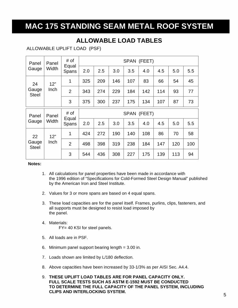
ALLOWABLE LOAD TABLES ALLOWABLE UPLIFT LOAD (PSF)
SPAN (FEET) Panel Gauge
Panel Width
# of Equal Spans 2.0 2.5 3.0 3.5 4.0 4.5 5.0 5.5
1 325 209 146 107 83 66 54 45
2 343 274 229 184 142 114 93 77
24
Gauge Steel
12” Inch
3 375 300 237 175 134 107 87 73
SPAN (FEET) Panel Gauge
Panel Width
# of Equal Spans 2.0 2.5 3.0 3.5 4.0 4.5 5.0 5.5
1 424 272 190 140 108 86 70 58
2 498 398 319 238 184 147 120 100
22
Gauge Steel
12” Inch
3 544 436 308 227 175 139 113 94
Notes:
1. All calculations for panel properties have been made in accordance with the 1996 edition of “Specifications for Cold-Formed Steel Design Manual” published by the American Iron and Steel Institute.
2. Values for 3 or more spans are based on 4 equal spans.
3. These load capacities are for the panel itself. Frames, purlins, clips, fasteners, and
all supports must be designed to resist load imposed by the panel.
4. Materials: FY= 40 KSI for steel panels. 5. All loads are in PSF. 6. Minimum panel support bearing length = 3.00 in.
7. Loads shown are limited by L/180 deflection. 8. Above capacities have been increased by 33-1/3% as per AISI Sec. A4.4.
9. THESE UPLIFT LOAD TABLES ARE FOR PANEL CAPACITY ONLY.
FULL SCALE TESTS SUCH AS ASTM E-1592 MUST BE CONDUCTED TO DETERMINE THE FULL CAPACITY OF THE PANEL SYSTEM, INCLUDING CLIPS AND INTERLOCKING SYSTEM.
5

MAC 175 STANDING SEAM METAL ROOF SYSTEM
NEGATIVE DESIGN LOADS
ULTIMATE TEST
LOAD (PSF) SPAN
(FT) DESIGN LOAD
(PSF)
2 104.3 69.4 2.5 - 65.9 3 - 62.4 3.5 - 59.0 4 - 55.5 4.5 - 52.0 5 73.1 48.6
Notes:
1. The above loads were derived from uplift tests done in accordance with ASTM E 1592-01 (see Farabaugh E ngineering and Testing, Inc. Test Report No. 103-02 for specific test data)
2. D esign values are interpolated from tests performed at spans of
2’-0” and 5’-0” only.
3. D esign load contains a 2.0 factor of safety and a 33% increase due to wind per AISI 96, Sec. A4.4.
4. Materials: FY = 50 K SI for steel panels. 5. All loads are in PSF. 6. Minimum panel support bearing length = 3.00 in.
6

MAC 175 STANDING SEAM METAL ROOF SYSTEM
CLIP AND PANEL END DETAILS
NOTES 1. Fill end of panel seam at eave and valleys with urethane sealant. 2. For UL90 rating, UL90 clips with two fasteners must be used.
7

MAC 175 STANDING SEAM METAL ROOF SYSTEM
Maximum Roof Panel Length Maximum length of roof panel is 150’ One-piece clip offers unimpeded thermal movement and does not restrict length of multiple panel runs.
2-1/4”
2”
1-3/4”
1-1/2”
1-1/4”
1”
3/4”
1/2”
1/4”
Total Thermal Movement (in.) Temperature
Differential (deg F) 250 deg F 200 deg F 150 deg F 100 deg F 50 deg F
Panel Fixing Information Standing seam roof panels must be fixed at any one of the following places: E ave, ridge, hip, or an intermediate location for longer length panels. (Note structural requirement for reinforcing supports at fixing lines.) Steel panels 30’-0” long or less may be fixed at eave and ridge, peak, or hip. Fixing of the eave is preferred when gutters are subject to high wind loads. See graph (Fig. 1) for steel thermal movement for temperature changes from 50 deg F to 250 deg F.
THERMAL MOVEMENT
10’ 20’ 30’ 40’ 50’ 60’ 70’ 80’ 90’ 100’ D istance From a Fixed Point (ft)
FIG. 1 – LINEAR THERMAL EXPANSION FOR STEEL PANELS
8