ma1008e & em wi587e.09 inst - alarm sms manual/napco/napco installer manu… · computer-based...
TRANSCRIPT
MA1008e / 1008eM Installation Instructions L NAPCO Security Systems
Page 1
INSTALLATION INSTRUCTIONS
M A G N U M A L E R T 1 0 0 8 e / 1 0 0 8 e M CONTROL PANEL / COMMUNICATOR
WI587E 8/07 © NAPCO 2007
R
UL / cUL Listed MA1008e: Household Fire & Burglary Warning System Control Unit
MA1008eM: Commercial Burglar Alarm System Control Unit
See page 10 for a summary of changes from the previous edition
Publicly traded on NASDAQ Symbol: NSSC
MAGNUM ALERT 1000 SERIES
COMPUTERIZED SECURITY SYSTEM
MA1008e / 1008eM Installation Instructions L NAPCO Security Systems
Page 2
NAPCO Security Systems, Inc. 333 Bayview Avenue, Amityville, New York 11701
For Sales and Repairs, call toll free: (800) 645-9445 For direct line to Technical Service, call toll free: (800) 645-9440
Internet: http://www.napcosecurity.com
Index starts on page 28
TABLE OF CONTENTS
1. INTRODUCTION ......................................................................................................3 GENERAL DESCRIPTION .......................................................................................3 FEATURES ...............................................................................................................3 SPECIFICATIONS ....................................................................................................4 ORDERING INFORMATION .....................................................................................4 UL/CUL LISTINGS ....................................................................................................4 COMPATIBLE UL-LISTED DEVICES ......................................................................4 SUMMARY OF UL REQUIREMENTS ......................................................................5
2. INSTALLATION .......................................................................................................6
CONTROL-PANEL MOUNTING ...............................................................................6 KEYPAD MOUNTING ..............................................................................................6 WIRING TO A MERCANTILE BELL ..........................................................................7 TYPICAL FIRE INSTALLATION ..............................................................................7
3. GETTING UP AND RUNNING ..................................................................................8
POWER-UP SEQUENCE .........................................................................................8 DEFAULT PROGRAM ..............................................................................................8 CENTRAL STATION REPORTING ...........................................................................8 USER KEYPAD PROGRAMMING ...........................................................................8 KEYPAD OPERATION .............................................................................................9 TESTING THE SYSTEM ..........................................................................................10 CHANGES FROM PREVIOUS EDITION ..................................................................10
4. PROGRAMMING ......................................................................................................11
KEYPAD PROGRAMMING .......................................................................................11 PROGRAMMING SHEETS .......................................................................................12 DOWNLOADING FROM A COMPUTER .................................................................13 PROM PROGRAMMING ..........................................................................................13
5. GLOSSARY & PROGRAMMING DATA ...................................................................17 6. WIRING DIAGRAM ..................................................................................................31
Section Page
MA1008e / 1008eM Installation Instructions L NAPCO Security Systems
Page 3
GENERAL DESCRIPTION The MAGNUM ALERT-1008e and MA1008eM are micro-
computer-based eight-zone control panels with provisions for Ambush, three Keypad Panics (Fire, Police and Auxiliary), a supervised Fire Zone and a variety of reporting features. An event log, accessible only through Napco PCD2000 Quick-loader software, monitors up to 82 prior events. The MA1008eM "Mercantile" version is supplied with a heavy-duty enclosure for increased tamper resistance and a tamper switch for tamper protection. (Note: Do not use Fire Zones in a Mercantile Installation).
The system is contained within a wall-mounted enclosure and Includes an integral digital communicator and a power transformer.
The keypad allows the user to: • arm and disarm the system • check the status of each zone • check which zones were violated after an alarm • selectively bypass one or more zones • display bypassed zones • cancel entry delay • send a Panic or Ambush alarm • enter or change arm/disarm codes • test the audible alarm and backup battery • test each zone for problems (Fault Find) • test the telephone line while disarmed • reset AC-Failure indication • bypass a Priority Zone with Bypass • turn the Chime feature on/off • program zone features and communicator information
Four LEDs, a display and a sounder an the keypad provide
visual and audible system and individual zone status Informa-tion. Most keys have secondary functions that are accessed by holding down the key until the sounder beeps, and are therefore termed "hold-down" functions. The following hold-down functions are provided:
Key [1]: Alarm Test Key [2]: Display Bypassed Zones Key [3]: Display Status Key [4]: Instant Alarm (cancels entry delay) Key [5]: Chime on/off Key [6]: Communicator Confidence Test or Manual
Download (see text) Key [7]: Fault Find Key [8]: Program Key [9]: Reset (System-trouble indication; Failure-to-
Communicate sounder; Day Zone Indication; Alarm-Memory display; Fire Zone; Fault-Find mode; Bypass Priority-with-Bypass; and Power-Up Delay)
Key [B]: Alarm History (indicates last alarmed zone(s))
The panels may be programmed in a variety of ways: (a)
from the keypad, in its secondary Dealer-Program Mode of operation; (b) from a PROM (programmable read-only mem-ory), which is itself programmed on an accessory program-mer; or (c) from an IBM PC-compatible computer using
Napco's PCD-Windows Quickloader Download Software. Designed for use with the PCI2000 Computer Interface Kit,
the MA1008e includes a modem to permit remote download-ing/uploading over telephone lines or local downloading using a PCL2000 Local Download Cable.
FEATURES Protection Zones
• Seven end-of-line-resistor supervised zones. • Two separately-programmable entry delays for Exit/
Entry Zones. • Burglary Zone options include:
- Priority or Priority with Bypass - Selective or Group Bypassing - 24-Hour Protection - Day Zone Supervision - Auto Reset - Exit/Entry Delay 1; Exit/Entry Delay 2 - Preprogrammed Auto Bypass (removable) - Optional 50mS or 7mS Loop Response (normally
750mS) - Programmable Abort Delay - Fire on Burglary Zone
• Separate supervised Fire Zone • Three keypad panics
Alarm Outputs • Timed Burglary (sweep siren) and Fire (steady siren)
Output: Programmable by zone and time • Timed Fire Output: Fixed to dedicated and programmed
Fire Zones, programmable for time • Pulsing Steady Siren Output: Fixed to dedicated and
programmed Fire Zones, programmable for time • NTO (No Timed Output) Lug • Optional voltage on alarm
Keypad Functions • Keypad permits:
- Arm/Disarm Code Selection of up to 8 user codes, up to 4 digits each
- Digital Code Entry to arm and disarm system - Selective and Group Bypass Selection - Panic Zone Activation - Ambush Activation - Hold-Down Function Access - Resetting of various functions and conditions - Programming zone features and communicator options
• LED display: - Alarm State (armed/disarmed) (ARMED/ALARM) - Zone Status (STATUS) - one or more zones in trouble - Zones Bypassed - one or more zones removed - Fire Zone Status (FIRE/TROUBLE) - System troubles
• Display Indicates: - Zone(s) in alarm and alarm history - Zone(s) in trouble - Zone(s) bypassed - System troubles - Programmed data entries (Dealer Program Mode)
1. INTRODUCTION
MA1008e / 1008eM Installation Instructions L NAPCO Security Systems
Page 4
• Sounder signals: - Entry Delay in Progress - Hold-Down Function Accessed - Entry Door Opened while Disarmed (Chime) - System Armed with a Zone in Trouble - Day Zone in Trouble - Fire Zone Alarm/Trouble - Central-Station Ringback - Failure-to-Communicate system trouble - Exiting Dealer Program Mode
Communicator Features
• Integral digital communicator with true dial tone detec-tion, double-pole line seizure and anti-jam
• Programmable abort delay time • Rotary or Touch-Tone® dialing available. Rotary dialing
available as backup to unsuccessful Touch-Tone® dial-ing
• Two telephone numbers and receiver/data formats can be accessed
• Two-digit event codes and 4-digit subscriber codes pro-grammable for those receivers accepting these formats
• Central-Station Ringback on closing or Auxiliary panic
Reporting Features • Report on Alarm • Opening and/or Closing Reporting by Individual User • Opening Report After Alarm • Day Zone Trouble; Fire Zone Trouble • Ambush; Panic; Keypad Auxiliary Panic • Test Timer; Reset Test Timer on Report • AC Failure; Low-Battery Report • Force-Arm Report; Force-Arm/Status Report . • Control-Panel Restore Report; Zone-Restore Report • Backup Reporting; Double Reporting; Split Reporting
Other Features • Supports NAPCO's Super Spectrum's Wireless System • Audible Bell-Test on Arming • Power-Up in Last State • Programmable Chime Duration • Chine/Display Chime Mode • No End-of Line Resistor • Watch Mode • Sensor Watch™ • 2- or 4-Wire Smoke Detector Compatibility on dedicated
Fire Zone • Electronic Dealer lockout prevents unauthorized access
SPECIFICATIONS
Operating Temperature: 0-49 °C (32-120 °F) Input Power: 16VAC, Class 2 step-down transformer TRF12
(19.2VA) or TRF11* (40VA) Loop Voltage: 10-13 VDC Loop Current: 2.8mA (normal resistance) Loop Resistance: 300Ω maximum series resistance Alarm Output (Burg/Fire): Commercial, 12-12.5VDC, 1.2A
maximum; Residential, 10.9-12.5VDC, 125mA max. (Dry) Contact Ratings: 24VDC, 2A (resistive)
Auxiliary Output: Commercial, 12VDC regulated; Residen-tial, 10.6-12.5VDC
Combined Standby Current: (Remote Power + Aux. Output + Relay Output) 450mA maximum with standard TRF12; 500mA maximum with optional TRF11
Remote Station, Current: 35mA typical Maximum Number: 5 Recommended Battery: Rechargeable, sealed-acid,
(12VDC, 4AH) or (12VDC, 7AH) Standby Time: See Wiring Diagram Fuses, Burglary/Fire Output: 3A, 1AG (F2) Remote Power: 1A, 1AG (F3) Battery: 3A, Over Current Protection Housing Dimensions: MA1008e, 12.6 x 14.1 x 3.6" (32 x 36
x 9.1cm) HxWxD; MA1008eM, 13.3 x 13.3 x 3.8" (33.8 x 33.8 x 9.7cm) (HxWxD)
Shipping Weight: MA1008e, Approx. 14lb. (6.4kg); MA1008eM, Approx. 11lb. (5.0kg)
*The TRF11 (40VA) Transformer and RBAT6 (7AH) Battery are required for Mercantile installations.
ORDERING INFORMATION Equipment Supplied
MA1008e - Residential 8 -zone (7 Burglary; 1 Fire; 3 Key-pad Panics) 12-volt alarm control panel with integral com-municator and siren driver, RP1054e keypad, 4AH and TRF12 power transformer.
MA1008eM--As above, but for Mercantile installations. Less keypad and battery, but with heavy-duty enclosure, Tam-per Switch and TRF11 40VA power transformer.
Optional Peripherals and Accessories
RP1054e Designer-Style 4-Wire Keypad RP1000eLCD Designer-Style Keypad with LCD display RBAT-H1* Dual Battery Harness (not for UL installations) TRF11 Transformer, 16VAC 40VA, Class 2 (UL Listed) TRF12 Transformer, 16VAC, 19.2VA, Class 2 (UL Listed) EOL2.2K End-of-Line Resistor Assembly, 2.2kΩ. FT2200 End-of-Line Relay/Resistor Supervisory Module PS3002 Power-Supply Module MAV-15 Two-Way Voice/Listen In Module GSM-400 Ground Start Module LOCK-8 Lock & Key Set PCI2000 Quickloader Interface and Software PCL2000 Quickloader Local Download Cable WL1 Wire with Lug Connector, 20" *UL Listed Accessory
UL/cUL LISTINGS Household Fire and Burglary Warning System Control Unit.
Combination Fire and Burglary (see Compatible UL Listed Devices), Commercial Burglary (MA1008eM)
COMPATIBLE UL-LISTED DEVICES (See Note below) For Residential control panels: Smoke Detectors: 4-Wire:
System Sensor 1812, 2812TH, 1851B, 2851B, 2851BTH, each with B102 Base
ESL 445AT*, 445C, 445CT, 445CR, 445CRT
MA1008e / 1008eM Installation Instructions L NAPCO Security Systems
Page 5
Gentex 812, 812T, 812P, 812PT, 812PH, 8120, 8120T, 8120P, 8120PT, 8120PH
Hochiki SLG with YBC-RL4-RA Base 2-Wire
System Sensor 1400*, 2400*, 2400TH*, each with B101B Base; 1451*, 2451*, 2451TH*, each with B401B Base
Subtract total smoke-detector alarm current from a available standby current.
Horn:
Wheelock 34T-12R* (Rated at 85dB for indoor household applications)
*Note: Devices not identified with an asterisk (*) require optional power supply PS3002 for UL installations. Compati-bility of detectors without "*" has not been evaluated by UL.
For Mercantile control panels (MA1008eM) Bells:
Ademco AD8-12, AD10-12 Amseco MBL-8/12V, -10/12V
Mercantile Bell: Ademco AB-12, Bell in Box
Speakers: Ademco 713 Atlas Sound VT-158U
SUMMARY OF UL REQUIREMENTS Note: The MA1008e may not be used for fire protection
where prohibited by local codes. The MA1008eM may not be used for fire protection in any installation.
Residential The following summarizes UL programming and wiring
requirements for Residential Household Fire and Burglary installations. • Recognized Limited-Energy Cable for initiating, indicat-
ing and supplementary circuits; • Initiating loops supervised if longer than 3 feet; • FT2200 End-of-Line Relay for Fire (if using 4-wire smoke
detectors); • Minimum alarm timeout of 4 minutes; • Maximum exit time: 60 seconds; maximum entry time:
45 seconds; • Do not program Don't Wait for Handshake, Telco 1 & 2;
Swinger Shutdown; Force Arming; Group Bypass; 7mS or 50mS Loop Response. Abort Delay may not exceed 45 seconds.
• Program Disable Callback Download; Disable Function 6 Download;
• Key Input on Zone 7 feature may not be enabled; • Automatic dialer may not dial a police-station number
that has not been dedicated for such service; • System must be tested at least weekly under AC battery
and battery-only conditions; • Replace the rechargeable battery at least every 5 years; • If the battery is heavily discharged, replace it or have it
tested by a qualified technician; • Remote panic switches must be located in the same
room as the control unit and keypad. Wiring may not
pass through any barrier; • For silent panic, connect only to UL-Listed holdup de-
vices. In California: CFM-Ilsted for residential use (Listing No. 7165-992:111).
Mercantile The following summarizes UL programming and wiring
requirements for Mercantile installations. • TRF11 (40VA) and RBAT6 (7AH) are required; • Heavy-duty enclosure with door tamper (MA1008eM) is
required; • Digital communicator must be utilized for Low Battery
reporting, but not Low Battery restore; • Program Audible Test on Arming; Force-Arm Code; a
maximum exit delay of 10 seconds; Disable Display By-pass; Auto-Reset;
• Do not use Fire Zones; • Ademco AB12 Bell & Box is required.
MA1008e / 1008eM Installation Instructions L NAPCO Security Systems
Page 6
CONTROL-PANEL MOUNTING Choose a mounting location accessible to (a) a continu-
ously-powered AC source, (b) a cold-water-pipe ground ide-ally no further away than 10 feet, and (c) telephone lines (keep telephone wiring away from speaker wires). Remove appropriate knockouts for cables. Place the control panel at a convenient viewing height and mark the mounting holes.
A keypad should be located near the exit/entry door. Up to 5 keypads may be connected if the longest cable run from the panel to the farthest keypad, whether daisy chained or home-run wired, is less than 1800 feet. See Combined Standby Current specifications. Each keypad typically draws 35mA, however do not use more than 5 keypads.
The control panel door is secured shut by 3 screws (supplied). A lock and keyset are available as an option (see ORDERING INFORMATION).
Grounding Connect the mounting screw at the lower-left corner of the
circuit board (EARTH GROUND) to a metal cold water pipe. Do not use a gas pipe, plastic pipe or AC ground connec-tions. Use at least 16-gauge wire. Make the run as short and direct as possible. Avoid sharp bends in the wire.
Tamper Switches Tamper switches may be installed to prevent opening of
the enclosure door or removal of the cabinet from the wall. Ideally, tamper switches should be connected to a zone that is active at all times, thus it may be necessary to program that zone for 24-Hour Protection. When used on a normally-open zone, normally-closed tamper switches (open when set) should be wired in parallel. On a normally-closed zone, in-stall Napco normally-open tamper switches (closed when set) in series. There are two tamper switch provisions in the cabi-net:
1. To prevent cabinet removal from the wall, there are three mounting holes on the left side of the cabinet; another hole on the back that allows the switch button to contact the wall.
2. To prevent opening the cabinet door, there are three mounting holes on the right side of the cabinet. When mounted, the tamper-switch button should contact the inside of the door. Be sure to alert the user that opening the enclosure door will cause a tamper alarm.
KEYPAD MOUNTING (Keypad model RP1054e)
Opening the keypad. There are two slats along the bot-tom edge of the keypad about 1 inch from each side. To open, insert a medium screwdriver into either slot and push up with a slight twisting motion to release the retainer tab. Repeat for the other slot. Pull out at the bottom and lift off the two hooks at the top.
This keypad features a handy pull-up reference label. Be-fore mounting the keypad onto the wall, push the Sliding La-bel Plate (with label and felt backing affixed and handle facing forward) down the guides at the rear of the keypad until it snaps into place. Once installed, the Sliding Label Plate can-not be removed without first removing the keypad from the wall.
When installing the rear case, be sure that the words "TOP" and "UP" (molded into the case) are properly oriented.
The rear case is provided with a variety of holes to accommo-date virtually any mounting situation. The four angled elon-gated holes are for mounting directly into a wall using appro-priate screws; these holes will allow leveling adjustment. If installing into a double-gang box, insert mounting screws through the two vertical elongated holes on the left side of the case and into the box. If the box is visible when viewed from the front, adjust the keypad vertically, then tighten the screws. Then, using hardware suitable far the mounting surface, add one or two screws at the right side of the keypad case directly into the wall to ensure a secure installation.
Keypad Wiring (Also see Wiring Diagram)
Connections to the keypad are summarized in the following table. Avoid routing keypad wiring close to zone wiring.
Note: If using a soldering iron, avoid splashing solder onto keypad circuit board or components.
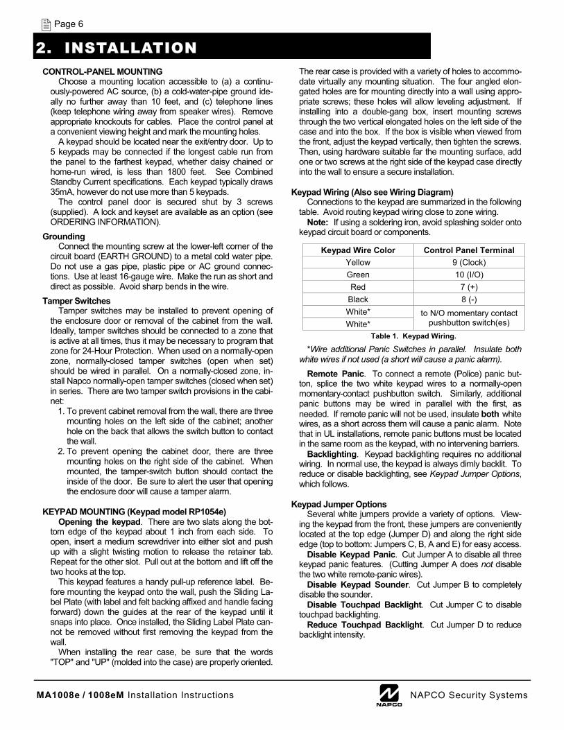
*Wire additional Panic Switches in parallel. Insulate both white wires if not used (a short will cause a panic alarm).
Remote Panic. To connect a remote (Police) panic but-ton, splice the two white keypad wires to a normally-open momentary-contact pushbutton switch. Similarly, additional panic buttons may be wired in parallel with the first, as needed. If remote panic will not be used, insulate both white wires, as a short across them will cause a panic alarm. Note that in UL installations, remote panic buttons must be located in the same room as the keypad, with no intervening barriers.
Backlighting. Keypad backlighting requires no additional wiring. In normal use, the keypad is always dimly backlit. To reduce or disable backlighting, see Keypad Jumper Options, which follows.
Keypad Jumper Options
Several white jumpers provide a variety of options. View-ing the keypad from the front, these jumpers are conveniently located at the top edge (Jumper D) and along the right side edge (top to bottom: Jumpers C, B, A and E) for easy access.
Disable Keypad Panic. Cut Jumper A to disable all three keypad panic features. (Cutting Jumper A does not disable the two white remote-panic wires).
Disable Keypad Sounder. Cut Jumper B to completely disable the sounder.
Disable Touchpad Backlight. Cut Jumper C to disable touchpad backlighting.
Reduce Touchpad Backlight. Cut Jumper D to reduce backlight intensity.
2. INSTALLATION
Keypad Wire Color Control Panel Terminal Yellow 9 (Clock) Green 10 (I/O) Red 7 (+)
Black 8 (-) White* White*
Table 1. Keypad Wiring.
to N/O momentary contact pushbutton switch(es)
MA1008e / 1008eM Installation Instructions L NAPCO Security Systems
Page 7
Activate Fire & Aux. Panics. Cut Jumper E to enable F/
P/A keypad panics. Note: This jumper must be cut to utilize the three-keypad-panic feature of the MA1088e. Conversely, if the jumper is cut, Enable Keypad Fire Panic or Enable Key-pad Auxiliary Panic must be programmed or adverse opera-tion will result.
Assembling the Keypad. To reassemble the keypad af-
ter installation, hang the top of the front panel onto the hooks in the rear case and push in firmly at the bottom until the re-tainer tabs snap into place. (If difficulty is encountered, push the retainer tabs up lightly using a screwdriver, as when re-moving).
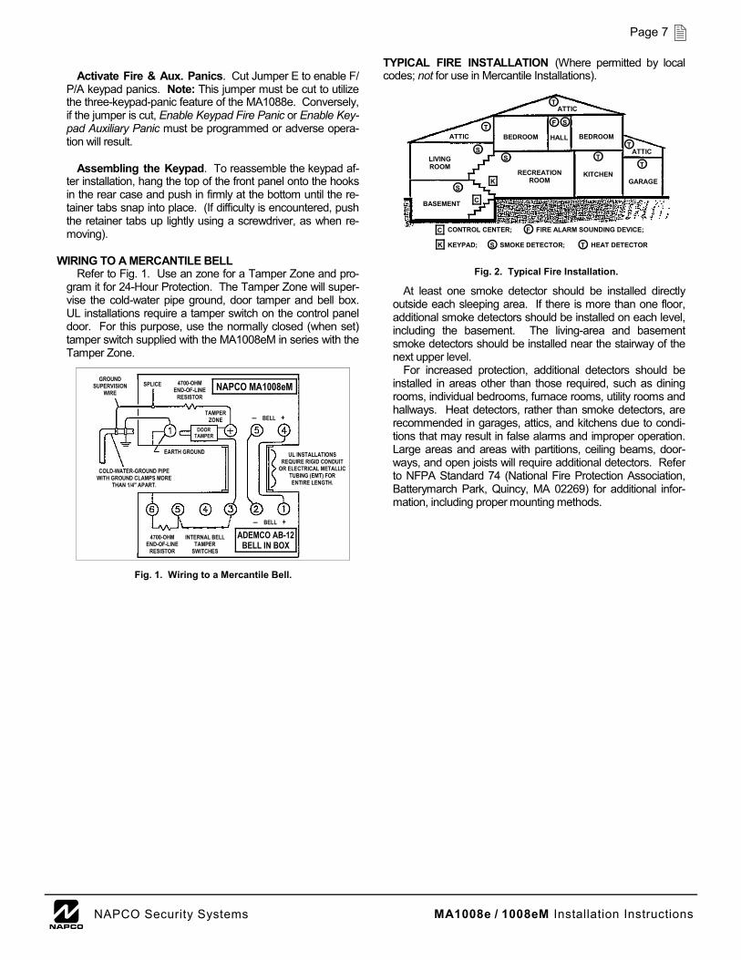
WIRING TO A MERCANTILE BELL
Refer to Fig. 1. Use an zone for a Tamper Zone and pro-gram it for 24-Hour Protection. The Tamper Zone will super-vise the cold-water pipe ground, door tamper and bell box. UL installations require a tamper switch on the control panel door. For this purpose, use the normally closed (when set) tamper switch supplied with the MA1008eM in series with the Tamper Zone.
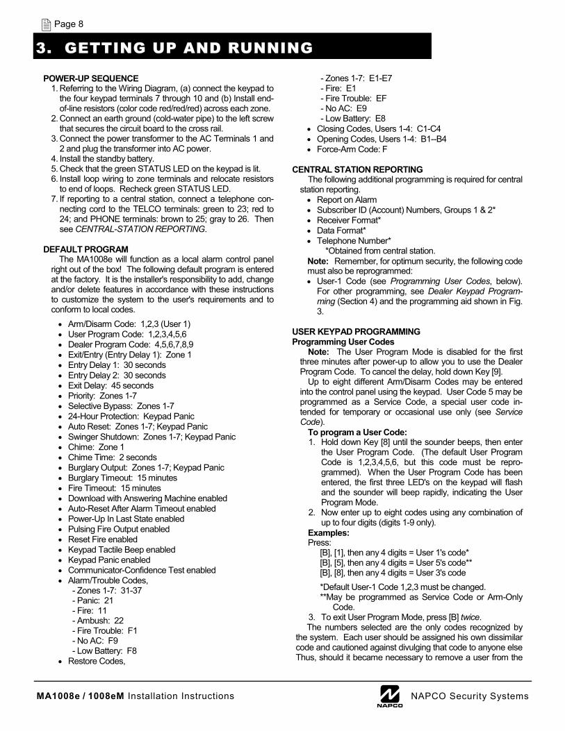
TYPICAL FIRE INSTALLATION (Where permitted by local codes; not for use in Mercantile Installations).
At least one smoke detector should be installed directly outside each sleeping area. If there is more than one floor, additional smoke detectors should be installed on each level, including the basement. The living-area and basement smoke detectors should be installed near the stairway of the next upper level.
For increased protection, additional detectors should be installed in areas other than those required, such as dining rooms, individual bedrooms, furnace rooms, utility rooms and hallways. Heat detectors, rather than smoke detectors, are recommended in garages, attics, and kitchens due to condi-tions that may result in false alarms and improper operation. Large areas and areas with partitions, ceiling beams, door-ways, and open joists will require additional detectors. Refer to NFPA Standard 74 (National Fire Protection Association, Batterymarch Park, Quincy, MA 02269) for additional infor-mation, including proper mounting methods.
Fig. 1. Wiring to a Mercantile Bell.
COLD-WATER-GROUND PIPE WITH GROUND CLAMPS MORE
THAN 1/4" APART.
EARTH GROUND
GROUND SUPERVISION
WIRE SPLICE 4700-OHM
END-OF-LINE RESISTOR
NAPCO MA1008eM
― BELL + TAMPER
ZONE DOOR
TAMPER
UL INSTALLATIONS REQUIRE RIGID CONDUIT
OR ELECTRICAL METALLIC TUBING (EMT) FOR ENTIRE LENGTH.
ADEMCO AB-12 BELL IN BOX
― BELL +
INTERNAL BELL TAMPER
SWITCHES
4700-OHM END-OF-LINE
RESISTOR
Fig. 2. Typical Fire Installation.
BEDROOM HALL BEDROOM
ATTIC
S
T
S
S
S T
T T
F
K
C
ATTIC T
GARAGE KITCHEN RECREATION
ROOM
ATTIC
LIVING ROOM
BASEMENT
CONTROL CENTER; FIRE ALARM SOUNDING DEVICE; KEYPAD; SMOKE DETECTOR; HEAT DETECTOR
C F
K S T
MA1008e / 1008eM Installation Instructions L NAPCO Security Systems
Page 8
POWER-UP SEQUENCE 1. Referring to the Wiring Diagram, (a) connect the keypad to
the four keypad terminals 7 through 10 and (b) Install end-of-line resistors (color code red/red/red) across each zone.
2. Connect an earth ground (cold-water pipe) to the left screw that secures the circuit board to the cross rail.
3. Connect the power transformer to the AC Terminals 1 and 2 and plug the transformer into AC power.
4. Install the standby battery. 5. Check that the green STATUS LED on the keypad is lit. 6. Install loop wiring to zone terminals and relocate resistors
to end of loops. Recheck green STATUS LED. 7. If reporting to a central station, connect a telephone con-
necting cord to the TELCO terminals: green to 23; red to 24; and PHONE terminals: brown to 25; gray to 26. Then see CENTRAL-STATION REPORTING.
DEFAULT PROGRAM
The MA1008e will function as a local alarm control panel right out of the box! The following default program is entered at the factory. It is the installer's responsibility to add, change and/or delete features in accordance with these instructions to customize the system to the user's requirements and to conform to local codes.
• Arm/Disarm Code: 1,2,3 (User 1) • User Program Code: 1,2,3,4,5,6 • Dealer Program Code: 4,5,6,7,8,9 • Exit/Entry (Entry Delay 1): Zone 1 • Entry Delay 1: 30 seconds • Entry Delay 2: 30 seconds • Exit Delay: 45 seconds • Priority: Zones 1-7 • Selective Bypass: Zones 1-7 • 24-Hour Protection: Keypad Panic • Auto Reset: Zones 1-7; Keypad Panic • Swinger Shutdown: Zones 1-7; Keypad Panic • Chime: Zone 1 • Chime Time: 2 seconds • Burglary Output: Zones 1-7; Keypad Panic • Burglary Timeout: 15 minutes • Fire Timeout: 15 minutes • Download with Answering Machine enabled • Auto-Reset After Alarm Timeout enabled • Power-Up In Last State enabled • Pulsing Fire Output enabled • Reset Fire enabled • Keypad Tactile Beep enabled • Keypad Panic enabled • Communicator-Confidence Test enabled • Alarm/Trouble Codes,
- Zones 1-7: 31-37 - Panic: 21 - Fire: 11 - Ambush: 22 - Fire Trouble: F1 - No AC: F9 - Low Battery: F8
• Restore Codes,
- Zones 1-7: E1-E7 - Fire: E1 - Fire Trouble: EF - No AC: E9 - Low Battery: E8
• Closing Codes, Users 1-4: C1-C4 • Opening Codes, Users 1-4: B1--B4 • Force-Arm Code: F
CENTRAL STATION REPORTING The following additional programming is required for central
station reporting. • Report on Alarm • Subscriber ID (Account) Numbers, Groups 1 & 2* • Receiver Format* • Data Format* • Telephone Number*
*Obtained from central station. Note: Remember, for optimum security, the following code must also be reprogrammed: • User-1 Code (see Programming User Codes, below).
For other programming, see Dealer Keypad Program-ming (Section 4) and the programming aid shown in Fig. 3.
USER KEYPAD PROGRAMMING Programming User Codes
Note: The User Program Mode is disabled for the first three minutes after power-up to allow you to use the Dealer Program Code. To cancel the delay, hold down Key [9].
Up to eight different Arm/Disarm Codes may be entered into the control panel using the keypad. User Code 5 may be programmed as a Service Code, a special user code in-tended for temporary or occasional use only (see Service Code).
To program a User Code: 1. Hold down Key [8] until the sounder beeps, then enter
the User Program Code. (The default User Program Code is 1,2,3,4,5,6, but this code must be repro-grammed). When the User Program Code has been entered, the first three LED's on the keypad will flash and the sounder will beep rapidly, indicating the User Program Mode.
2. Now enter up to eight codes using any combination of up to four digits (digits 1-9 only).
Examples: Press:
[B], [1], then any 4 digits = User 1's code* [B], [5], then any 4 digits = User 5's code** [B], [8], then any 4 digits = User 3's code
*Default User-1 Code 1,2,3 must be changed. **May be programmed as Service Code or Arm-Only
Code. 3. To exit User Program Mode, press [B] twice. The numbers selected are the only codes recognized by
the system. Each user should be assigned his own dissimilar code and cautioned against divulging that code to anyone else Thus, should it became necessary to remove a user from the
3. GETTING UP AND RUNNING
MA1008e / 1008eM Installation Instructions L NAPCO Security Systems
Page 9
system, that one code may be voided without affecting other codes, and that user would then be prevented from entry.
Service Code
The Service Code, if programmed, provides reduced ac-cess to the control panel for those with limited authority. Op-eration is similar to that of a regular Arm/Disarm Code, except that the Service Code is disabled at times. When active, it may be used to arm or disarm as many times as necessary. See User 5 Service Code in the Glossary.
The Service Code is controlled by User 1 . Whenever User 1 arms using his code, the Service Code is deactivated. To activate, merely arm using the Service Code. The Service Code can always be used to arm.
Changing or Voiding a Code
To change any User's Code, refer to Programming User Codes and simply change the 4-digit combination. Thus, to change User 3's code, for example:
1. Hold down Key [8] until the function beep sounds. 2. Enter the User Program Code. 3. Press [B], [3], then 4 new digits = User 3's new code. 4. Press [B] twice to exit User Program Mode.
Similarly, User 3's code may be voided by not entering a 4-digit combination. Thus, to void User 3's code:
1. Hold down Key [8] until the function beep sounds. 2. Enter the User Program Code. 3. Press [B], then [3] = User 3's code erased. 4. Press [B] twice to exit User Program Mode.
KEYPAD OPERATION Arming & Disarming the System
When a User Code is entered into the keypad, the red ARMED / ALARM LED will either turn on, indicating that the panel is armed; or turn off, indicating that the panel is dis-armed. A "P" on the display with a steady sounder indicates an attempt to arm with (a) a system trouble (hold down [9] to reset keypad and arm), or (b) a Priority Zone in trouble (re-enter code, then secure or bypass zone). If a wrong code is entered, the system will fail to respond. Wait at least 2 sec-onds before attempting to re-enter a code.
Alarm Reset
Disarm the panel to silence a sounding device.
Ambush Zone The Ambush Zone is tripped by entering the Ambush Code
just prior to disarming. Thus, should a user be forced to dis-arm by an assailant, the user can silently signal an emergency while appearing to be merely disarming the system. The Arm/Disarm Code must be entered less than 10 seconds after the Ambush Code for an ambush report to be transmitted.
Keypad Panic
If using an F/P/A-Panic keypad, three keypad panics are available: Fire, Police and Auxiliary (cut keypad jumper to en-able panics). If enabled, each is tripped by simultaneously pressing the following pairs of panic buttons:
• Fire Panic: press Keys [9/F] and [#] • Police Panic: press Keys [*/P] and [#] • Auxiliary Panic: press Keys [B/A] and [#]
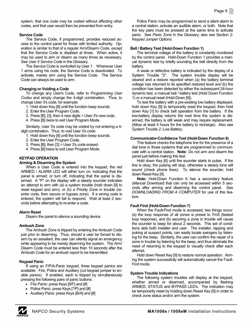
Police Panic may be programmed to send a silent alarm to a central station, activate an audible alarm, or both. Note that the key pairs must be pressed at the same time to activate panic. See Panic Zone In the Glossary; also see Section 2: Keypad Jumper Options.
Bell / Battery Test (Hold-Down Function 1)
The terminal voltage of the battery is constantly monitored by the control panel. Hold-Down Function 1 provides a man-ual dynamic test by briefly sounding the bell directly from the battery.
A weak or defective battery is indicated by the display of a System Trouble "2". The system trouble display will be cleared and a restore reported when (a) the battery terminal voltage has returned to its specified restored level and (b) the condition has been detected by either the subsequent 24-hour dynamic test, a manual bell / battery test (Hold Down Function 1) or a manual reset (Hold-Down [9]).
To test the battery with a pre-existing low battery displayed, hold down Key [9] to temporarily reset the keypad, then hold down Key [1] to check bell operation from the battery. If the low-battery display returns the next time the system is dis-armed, the battery is still weak and may require replacement. (Allow at least 4 hours for the battery to recharge). Also see System Trouble 2: Low Battery.
Communicator-Confidence Test (Hold-Down Function 6)
This feature checks the telephone line for the presence of a dial tone in those systems that are programmed to communi-cate with a central station. Note: Do not arm and disarm the panel just before making this test.
Hold down Key [6] until the sounder starts to pulse. If the line is okay, the pulsing will stop, otherwise a steady tone will sound (check phone lines). To silence the sounder, hold down Reset Key [9].
Note: Hold-Down Function 6 has a secondary feature (Manual Download) that can only be accessed within 5 sec-onds after arming and disarming the control panel. See DOWNLOADING FROM A COMPUTER for use of this fea-ture.
Fault Find (Hold-Down Function 7)
When the Fault-Find mode is accessed, two things occur: (a) the loop response of all zones is preset to 7mS (fastest loop response), and (b) securing a zone in trouble will cause the sounder to beep for about 2 seconds. This set of condi-tions aids both installer and user. The installer, tapping and poking at suspect points, can easily locate swingers by listen-ing for the beep. Similarly, the user can confirm the repair of a zone in trouble by listening for the beep, and thus eliminate the need of returning to the keypad to visually check after each attempt.
Hold down Reset Key [9] to restore normal operation. Arm-ing the system successfully will automatically cancel the Fault-Find mode.
System Trouble Indications
The following system troubles will display at the keypad, whether armed or disarmed, accompanied by flashing ARMED, STATUS and BYPASS LED's. The indication may be temporarily reset by holding down Reset Key [9] in order to check zone status and/or arm the system.
MA1008e / 1008eM Installation Instructions L NAPCO Security Systems
Page 10
1. AC Failure. Indicates loss of AC power. The AC-Failure
indication will clear when AC power is restored. 2. Low Battery. Displays when battery terminal voltage
drops below 11.5 volts, nominally. The system trouble dis-play will be cleared and a restore reported when (a) the battery terminal voltage has returned to its specified re-stored level and (b) the keypad is reset using Hold-Down Function 9. Also see Bell / Battery Test.
3. Failure to Communicate. Indicates an unsuccessful transmission to the central station. If the panel is armed, disarm. Hold down Key [9] to reset the keypad, then hold down Key [5] to test the phone lines. If the test is success-ful, the display will clear; otherwise the trouble will return, indicating a need for service. A successful communication followed by a Hold-Down [9] Reset will also clear the dis-play.
Note: If the system is armed and in alarm, the sounder will turn on but the violated zones will display, along with a
flashing red ARMED/ALARM LED. Subsequent disarming will initiate the system trouble indication.
4. Auto-Download Failure. Indicates failure of a Function-6 Auto-Download. Reset the display by holding down Key [9], then try again to auto-download the program.
TESTING THE SYSTEM After installation is completed, test the system a follows:
Call the central station to inform them of the test. Initiate an alarm, preferably on a zone that activates a steady output. Verify proper signaling, then call the central station to confirm their receipt of a good transmission.
Important: Be sure to test the operation of all enabled keypad-panic features.
CHANGES FROM PREVIOUS EDITION
The following changes have been made to this manual (WI587E) since the previous edition (WI587D):
• Cover: UL Listing text descriptions changed to "UL/cUL".
• Page 3: 2nd paragraph, removed text "If complemented by NAPCO wireless transmitters…" (to end of paragraph).
• Page 4, 5, 18: Recommended battery specifications changed.
• Pages 4-5: Removed ordering information for certain items, including wireless equipment.
• Page 5: Updated UL classification information.
• Page 5 and 7: Renamed "Grade-A Bell" to "Mercantile Bell".
• Page 5: In "Summary of UL Requirements", removed bullet referencing Battery Fuse.
• Page 5: Updated UL Mercantile requirement descriptions.
• Page 10: Removed steps 4-6.
• Page 17: Added row to table 4, "Temporal Fire" output.
• Page 22: Removed text "Note: A wireless transmitter mapped to Zone 7 may be used for remote arming." from "Key Input on Zone 7" description.
• Page 27: Removed entry, "Transmitters See R1000 Receiver Instructions WI604". • Index: Re-created index entries. • Page 31: Updated Wiring Diagram.
MA1008e / 1008eM Installation Instructions L NAPCO Security Systems
Page 11
KEYPAD PROGRAMMING Keypad Programming may be divided into two sub-groups:
User Program Mode and Dealer Program Mode. USER KEY-PAD PROGRAMMING is limited to user codes. In the Dealer Program Mode, the keypad provides full programming capa-bilities.
Dealer Keypad Programming.
Set the keypad to the Dealer Program Mode: Hold down Key [8] until a beep sounds, then enter the Dealer Program Code. (The default Dealer Program Code is 4,5,6,7,8,9, but this code must be reprogrammed to preserve system security. See Glossary and the programming example, which follows). The center segment of the numeric display will light to indicate the Dealer Program Mode.
The Dealer Program Mode cannot be accessed while the panel is armed or communicating except during the first three minutes after power-up. (See Power-Up Delay in Glossary). To shut this 3-minute "window" early, that is, before it times out, hold down Key [9]. Note: If the Dealer Program Mode has been accessed during this 3-minute "window", then complete the required programming, exit the Dealer Program Mode (see following), power down and power up the system once again.
Set the location to be programmed by pressing Key [B] (the three horizontal segments of the display and the green LED will light), followed by the location number. Each location must be entered as a three digit number, that is, 001, 020, 157, etc. Notice that as each of the three digits is entered, the three dis-play segments extinguish in succession from bottom to top. When the last digit is entered, the yellow LED will light and the display will show the data (if any) programmed in that location.
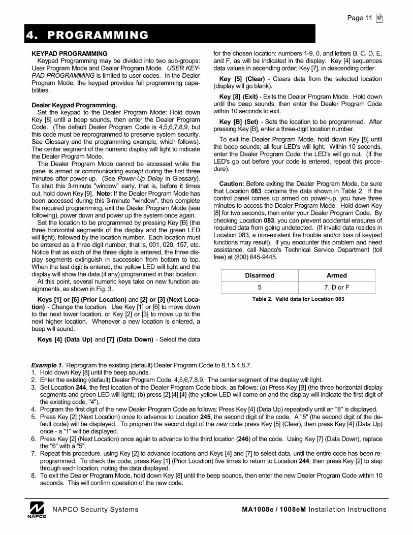
At this point, several numeric keys take on new function as-signments, as shown in Fig. 3.
Keys [1] or [6] (Prior Location) and [2] or [3] (Next Loca-tion) - Change the location. Use Key [1] or [6] to move down to the next lower location, or Key [2] or [3] to move up to the next higher location. Whenever a new location is entered, a beep will sound.
Keys [4] (Data Up) and [7] (Data Down) - Select the data
for the chosen location: numbers 1-9, 0, and letters B, C, D, E, and F, as will be indicated in the display. Key [4] sequences data values in ascending order; Key [7], in descending order.
Key [5] (Clear) - Clears data from the selected location (display will go blank).
Key [8] (Exit) - Exits the Dealer Program Mode. Hold down until the beep sounds, then enter the Dealer Program Code within 10 seconds to exit.
Key [B] (Set) - Sets the location to be programmed. After pressing Key [B], enter a three-digit location number.
To exit the Dealer Program Mode, hold down Key [8] until the beep sounds; all four LED's will light. Within 10 seconds, enter the Dealer Program Code; the LED's will go out. (If the LED's go out before your code is entered, repeat this proce-dure).
Caution: Before exiting the Dealer Program Mode, be sure
that Location 083 contains the data shown in Table 2. lf the control panel comes up armed on power-up, you have three minutes to access the Dealer Program Mode. Hold down Key [8] for two seconds, then enter your Dealer Program Code. By checking Location 083, you can prevent accidental erasures of required data from going undetected. (If invalid data resides in Location 083, a non-existent fire trouble and/or loss of keypad functions may result). If you encounter this problem and need assistance, call Napco's Technical Service Department (toll free) at (800) 645-9445.
Example 1. Reprogram the existing (default) Dealer Program Code to 8,1,5,4,8,7. 1. Hold down Key [8] until the beep sounds. 2. Enter the existing (default) Dealer Program Code, 4,5,6,7,8,9. The center segment of the display will light. 3. Set Location 244, the first location of the Dealer Program Code block, as follows: (a) Press Key [B] (the three horizontal display
segments and green LED will light); (b) press [2],[4],[4] (the yellow LED will come on and the display will indicate the first digit of the existing code, "4").
4. Program the first digit of the new Dealer Program Code as follows: Press Key [4] (Data Up) repeatedly until an "8" is displayed. 5. Press Key [2] (Next Location) once to advance to Location 245, the second digit of the code. A "5" (the second digit of the de-
fault code) will be displayed. To program the second digit of the new code press Key [5] (Clear), then press Key [4] (Data Up) once - a "1" will be displayed.
6. Press Key [2] (Next Location) once again to advance to the third location (246) of the code. Using Key [7] (Data Down), replace the "6" with a "5".
7. Repeat this procedure, using Key [2] to advance locations and Keys [4] and [7] to select data, until the entire code has been re-programmed. To check the code, press Key [1] (Prior Location) five times to return to Location 244, then press Key [2] to step through each location, noting the data displayed.
8. To exit the Dealer Program Mode, hold down Key [8] until the beep sounds, then enter the new Dealer Program Code within 10 seconds. This will confirm operation of the new code.
Disarmed Armed
5 7, D or F
Table 2. Valid data for Location 083
4. PROGRAMMING
MA1008e / 1008eM Installation Instructions L NAPCO Security Systems
Page 12
PROGRAMMING SHEETS Programming Sheets similar to those that follow are com-
pleted when planning system features and communicator in-formation for the particular installation. These sheets should be retained for future reference. The Glossary contains infor-mation and instructions for programming each feature.
General Programming Steps 1. Contact the central station to confirm receiver format, data
format, event codes, subscriber numbers and telephone number(s). Two receiver descriptions and telephone num-bers, and up to 4 Subscriber Identification Numbers may be required.
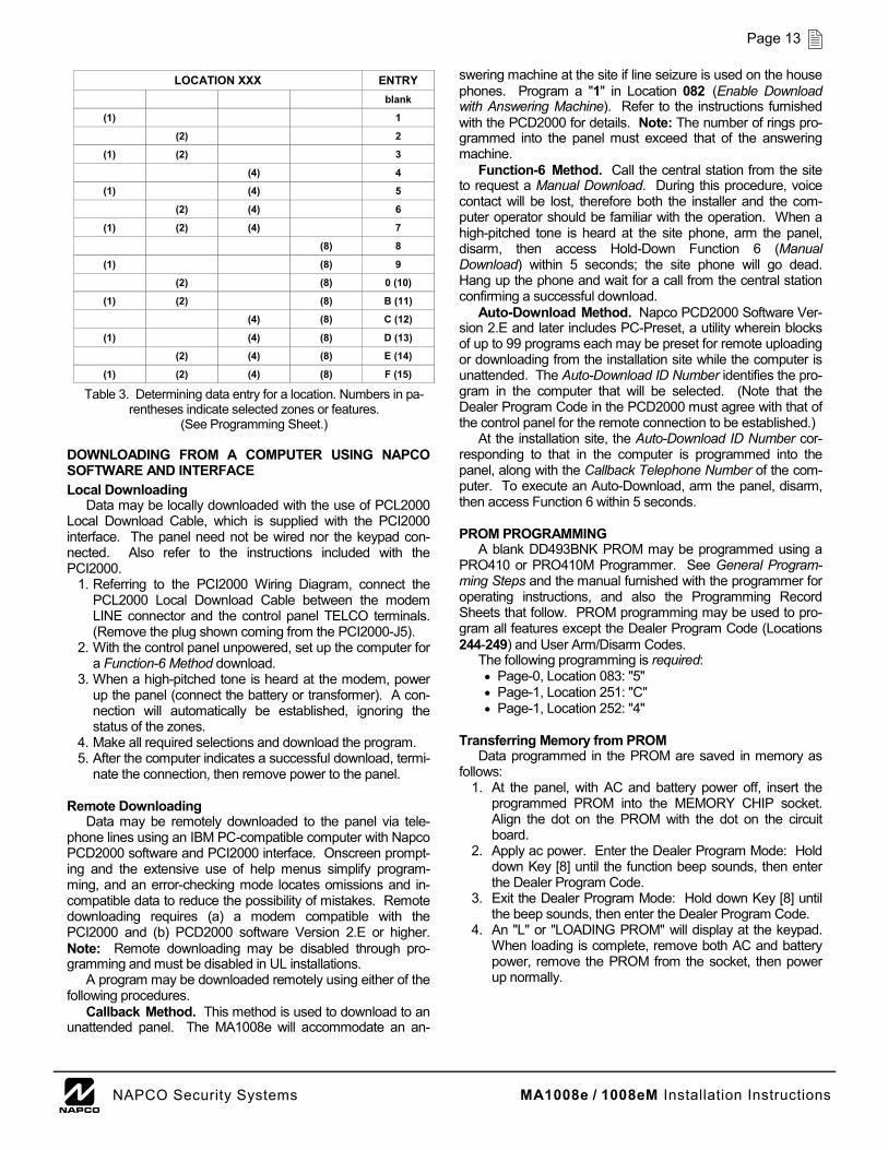
2. Fill out the Programming Record Sheets by circling the numbers representing the zone features or system features to be programmed. Referring to the programming sheets and the accompanying table, note that each program loca-tion is assigned data values (1, 2, 4, 8) such that adding any combination will produce a unique total (entry). Also note that because the entry can be only one character, the two-digit totals greater than 9 are replaced by zero and let-ters B through F, as shown. Check the Glossary for guid-ance in selecting "data" entries.
3. To program the subscriber PROM, follow the instructions furnished with the programmer. While programming, re-member to keep the address page number in mind, and be sure that the position of the PAGE switch (PRO410/410M) is set accordingly. Note: If using the Napco PRO410/410M programmer, before attempting to program either page, be sure that all data in programmer memory are erased (press [ERASE], then [EXECUTE]).
4. Program the entries (data totals from Programming Record Sheets in Step 2) into the respective locations. The display will show the entry numerically, but will display "0" for the number 10, and letters "B", "C", "D", "E", and "F" for the numbers 11 through 15, respectively. To program a 10, enter [0]. To program 11 through 15, enter [B] through [F] respectively, if using the Napco PRO410/410M program-mer to program a PROM, use the [PLUS] key to enter any two or more digits that add up to the desired entry. To pro-gram 13, for example, enter either [d] or [8] [PLUS] [5], or [8] [PLUS] [4] [PLUS] [1], etc. Similarly, to add to an exist-ing PROM location, first press the [PLUS] key, then the complementary digit, otherwise the digit entered will re-place the digit in memory. Refer to the PRO410/410M in-structions for further programming information.
ENTER/EXIT PROGRAM MODE HOLD DOWN KEY [8] UNTIL BEEP SOUNDS. ENTER DEALER PROGRAM CODE.
SEGMENTS LIT 2: PRESS "SET" (with no LED's lit) TO SET 3-DIGIT LOCATION.
3,2,1: ENTER 1ST OF 3 DIGITS. 3,2: ENTER 2ND OF 3 DIGITS. 3: ENTER 3RD DIGIT; DATA DISPLAYED.
2: ENTER DEALER CODE (with all LED's lit) TO EXIT.
LOCAT ION KEYS [1] (OR [8]) AND [2] (OR [3] ) BEEP = SHIFTED 1 LOCATION NO BEEP = NO SHIFT
LED'S LIT GREEN: .......... ENTER LOCATION DIGITS YELLOW: ........ VIEW/CHANGE DATA RED (RIGHT): . PAGE-1 LOCATION ALL: ................ READY TO EXIT
3 2 1
MAGNUM ALERT
COMPUTERIZED SECURITY SYSTEM
LOCATION DATA PAGE 1
LOCATION
PRIOR NEXT NEXT DATA UP
CLEAR PRIOR DATA DOWN ENTER/EXIT
SET
2 1 3 4
5 6 7 8
9 F # P * A B
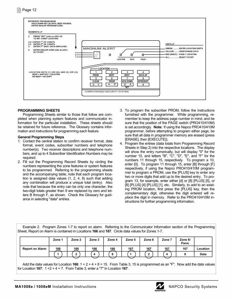
Example 2. Program Zones 1-7 to report on alarm. Referring to the Communicator Information section of the Programming Sheet, Report on Alarm is contained in Locations 166 and 167. Circle data values for Zones 1-7.
Add the data values for Location 166: 1 + 2 + 4 + 8 = 15. From Table 3, 15 is programmed as an "F". Now add the data values for Location 167: 1 +2 + 4 = 7. From Table 3, enter a "7" In Location 167.
Zone 1 Zone 2 Zone 3 Zone 4 Zone 5 Zone 6 Zone 7 Zone 8/Panic
166 166 166 166 167 167 167 167 Location
1 2 4 8 1 2 4 8 Data
Report on Alarm
MA1008e / 1008eM Installation Instructions L NAPCO Security Systems
Page 13
DOWNLOADING FROM A COMPUTER USING NAPCO SOFTWARE AND INTERFACE
Local Downloading Data may be locally downloaded with the use of PCL2000
Local Download Cable, which is supplied with the PCI2000 interface. The panel need not be wired nor the keypad con-nected. Also refer to the instructions included with the PCI2000.
1. Referring to the PCI2000 Wiring Diagram, connect the PCL2000 Local Download Cable between the modem LINE connector and the control panel TELCO terminals. (Remove the plug shown coming from the PCI2000-J5).
2. With the control panel unpowered, set up the computer for a Function-6 Method download.
3. When a high-pitched tone is heard at the modem, power up the panel (connect the battery or transformer). A con-nection will automatically be established, ignoring the status of the zones.
4. Make all required selections and download the program. 5. After the computer indicates a successful download, termi-
nate the connection, then remove power to the panel.
Remote Downloading Data may be remotely downloaded to the panel via tele-
phone lines using an IBM PC-compatible computer with Napco PCD2000 software and PCI2000 interface. Onscreen prompt-ing and the extensive use of help menus simplify program-ming, and an error-checking mode locates omissions and in-compatible data to reduce the possibility of mistakes. Remote downloading requires (a) a modem compatible with the PCI2000 and (b) PCD2000 software Version 2.E or higher. Note: Remote downloading may be disabled through pro-gramming and must be disabled in UL installations.
A program may be downloaded remotely using either of the following procedures.
Callback Method. This method is used to download to an unattended panel. The MA1008e will accommodate an an-
swering machine at the site if line seizure is used on the house phones. Program a "1" in Location 082 (Enable Download with Answering Machine). Refer to the instructions furnished with the PCD2000 for details. Note: The number of rings pro-grammed into the panel must exceed that of the answering machine.
Function-6 Method. Call the central station from the site to request a Manual Download. During this procedure, voice contact will be lost, therefore both the installer and the com-puter operator should be familiar with the operation. When a high-pitched tone is heard at the site phone, arm the panel, disarm, then access Hold-Down Function 6 (Manual Download) within 5 seconds; the site phone will go dead. Hang up the phone and wait for a call from the central station confirming a successful download.
Auto-Download Method. Napco PCD2000 Software Ver-sion 2.E and later includes PC-Preset, a utility wherein blocks of up to 99 programs each may be preset for remote uploading or downloading from the installation site while the computer is unattended. The Auto-Download ID Number identifies the pro-gram in the computer that will be selected. (Note that the Dealer Program Code in the PCD2000 must agree with that of the control panel for the remote connection to be established.)
At the installation site, the Auto-Download ID Number cor-responding to that in the computer is programmed into the panel, along with the Callback Telephone Number of the com-puter. To execute an Auto-Download, arm the panel, disarm, then access Function 6 within 5 seconds.
PROM PROGRAMMING
A blank DD493BNK PROM may be programmed using a PRO410 or PRO410M Programmer. See General Program-ming Steps and the manual furnished with the programmer for operating instructions, and also the Programming Record Sheets that follow. PROM programming may be used to pro-gram all features except the Dealer Program Code (Locations 244-249) and User Arm/Disarm Codes.
The following programming is required: • Page-0, Location 083: "5" • Page-1, Location 251: "C" • Page-1, Location 252: "4"
Transferring Memory from PROM
Data programmed in the PROM are saved in memory as follows:
1. At the panel, with AC and battery power off, insert the programmed PROM into the MEMORY CHIP socket. Align the dot on the PROM with the dot on the circuit board.
2. Apply ac power. Enter the Dealer Program Mode: Hold down Key [8] until the function beep sounds, then enter the Dealer Program Code.
3. Exit the Dealer Program Mode: Hold down Key [8] until the beep sounds, then enter the Dealer Program Code.
4. An "L" or "LOADING PROM" will display at the keypad. When loading is complete, remove both AC and battery power, remove the PROM from the socket, then power up normally.
LOCATION XXX ENTRY blank
(1) 1
(2) 2
(1) (2) 3
(4) 4
(1) (4) 5
(2) (4) 6
(1) (2) (4) 7
(8) 8
(1) (8) 9
(2) (8) 0 (10)
(1) (2) (8) B (11)
(4) (8) C (12)
(1) (4) (8) D (13)
(2) (4) (8) E (14)
(1) (2) (4) (8) F (15)
Table 3. Determining data entry for a location. Numbers in pa-rentheses indicate selected zones or features.
(See Programming Sheet.)
MA1008e / 1008eM Installation Instructions L NAPCO Security Systems
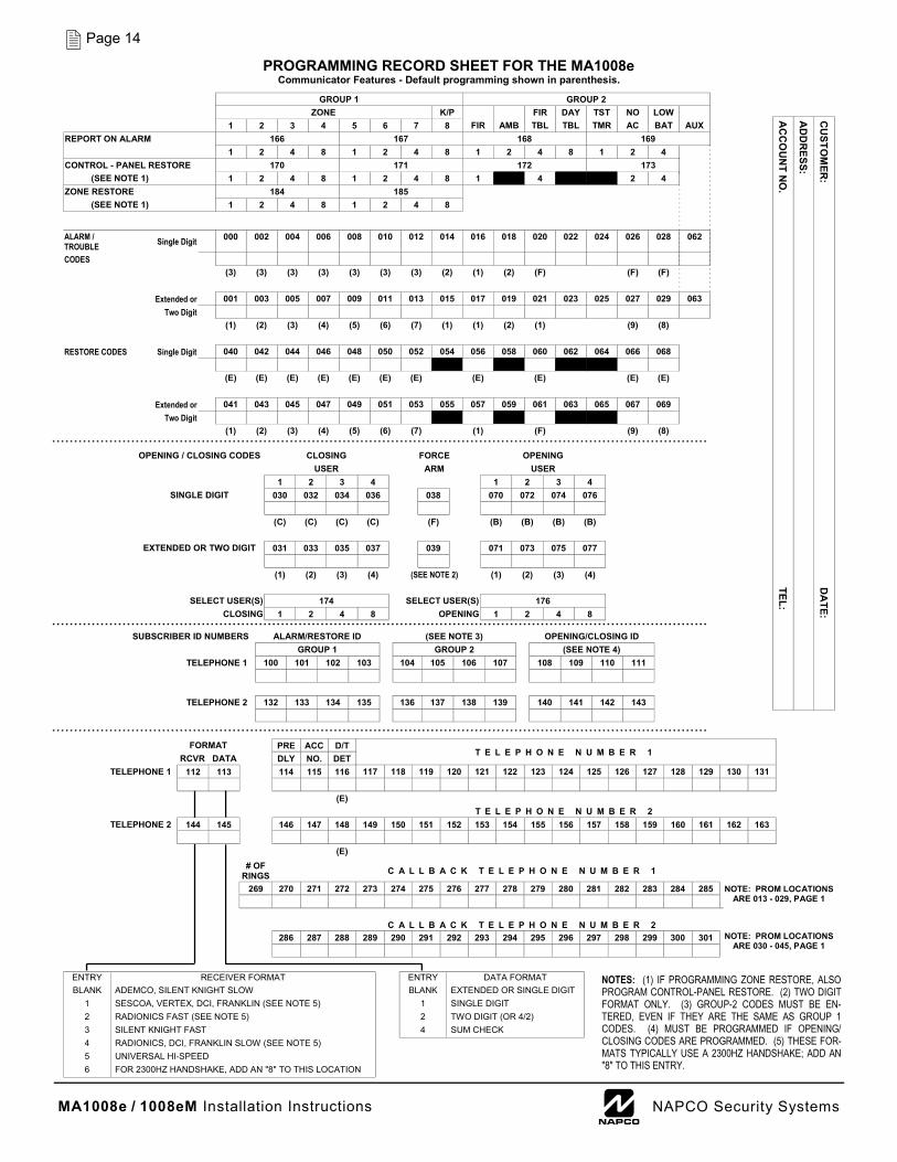
Page 14 PROGRAMMING RECORD SHEET FOR THE MA1008e
Communicator Features - Default programming shown in parenthesis. C
USTO
MER
: D
ATE:
AC
CO
UN
T NO
. TEL:
AD
DR
ESS: GROUP 1 GROUP 2 ZONE K/P FIR DAY TST NO LOW 1 2 3 4 5 6 7 8 FIR AMB TBL TBL TMR AC BAT AUX
REPORT ON ALARM 166 167 168 169 1 2 4 8 1 2 4 8 1 2 4 8 1 2 4 CONTROL - PANEL RESTORE 170 171 172 173
(SEE NOTE 1) 1 2 4 8 1 2 4 8 1 2 4 8 1 2 4 ZONE RESTORE 184 185
(SEE NOTE 1) 1 2 4 8 1 2 4 8
ALARM / TROUBLE Single Digit 000 002 004 006 008 010 012 014 016 018 020 022 024 026 028 062
CODES (3) (3) (3) (3) (3) (3) (3) (2) (1) (2) (F) (F) (F) Extended or 001 003 005 007 009 011 013 015 017 019 021 023 025 027 029 063 Two Digit (1) (2) (3) (4) (5) (6) (7) (1) (1) (2) (1) (9) (8) RESTORE CODES Single Digit 040 042 044 046 048 050 052 054 056 058 060 062 064 066 068 (E) (E) (E) (E) (E) (E) (E) (E) (E) (E) (E) Extended or 041 043 045 047 049 051 053 055 057 059 061 063 065 067 069 Two Digit (1) (2) (3) (4) (5) (6) (7) (1) (F) (9) (8)
OPENING / CLOSING CODES CLOSING FORCE OPENING USER ARM USER 1 2 3 4 1 2 3 4
SINGLE DIGIT 030 032 034 036 038 070 072 074 076 (C) (C) (C) (C) (F) (B) (B) (B) (B)
EXTENDED OR TWO DIGIT 031 033 035 037 039 071 073 075 077 (1) (2) (3) (4) (SEE NOTE 2) (1) (2) (3) (4)
SELECT USER(S) 174 SELECT USER(S) 176 CLOSING 1 2 4 8 OPENING 1 2 4 8
SUBSCRIBER ID NUMBERS ALARM/RESTORE ID (SEE NOTE 3) OPENING/CLOSING ID GROUP 1 GROUP 2 (SEE NOTE 4)
TELEPHONE 1 100 101 102 103 104 105 106 107 108 109 110 111 TELEPHONE 2 132 133 134 135 136 137 138 139 140 141 142 143
FORMAT
PRE ACC D/T T E L E P H O N E N U M B E R 1
RCVR DATA DLY NO. DET TELEPHONE 1 112 113 114 115 116 117 118 119 120 121 122 123 124 125 126 127 128 129 130 131
(E)
TELEPHONE 2 144 145 146 147 148 149 150 151 152 153 154 155 156 157 158 159 160 161 162 163 (E)
T E L E P H O N E N U M B E R 2
# OF RINGS C A L L B A C K T E L E P H O N E N U M B E R 1
269 270 271 272 273 274 275 276 277 278 279 280 281 282 283 284 285
286 287 288 289 290 291 292 293 294 295 296 297 298 299 300 301
C A L L B A C K T E L E P H O N E N U M B E R 2
NOTE: PROM LOCATIONS ARE 013 - 029, PAGE 1
NOTE: PROM LOCATIONS ARE 030 - 045, PAGE 1
ENTRY RECEIVER FORMAT BLANK ADEMCO, SILENT KNIGHT SLOW
1 SESCOA, VERTEX, DCI, FRANKLIN (SEE NOTE 5) 2 RADIONICS FAST (SEE NOTE 5) 3 SILENT KNIGHT FAST 4 RADIONICS, DCI, FRANKLIN SLOW (SEE NOTE 5) 5 UNIVERSAL HI-SPEED 6 FOR 2300HZ HANDSHAKE, ADD AN "8" TO THIS LOCATION
ENTRY DATA FORMAT BLANK EXTENDED OR SINGLE DIGIT
1 SINGLE DIGIT 2 TWO DIGIT (OR 4/2) 4 SUM CHECK
NOTES: (1) IF PROGRAMMING ZONE RESTORE, ALSO PROGRAM CONTROL-PANEL RESTORE. (2) TWO DIGIT FORMAT ONLY. (3) GROUP-2 CODES MUST BE EN-TERED, EVEN IF THEY ARE THE SAME AS GROUP 1 CODES. (4) MUST BE PROGRAMMED IF OPENING/CLOSING CODES ARE PROGRAMMED. (5) THESE FOR-MATS TYPICALLY USE A 2300HZ HANDSHAKE; ADD AN "8" TO THIS ENTRY.
MA1008e / 1008eM Installation Instructions L NAPCO Security Systems
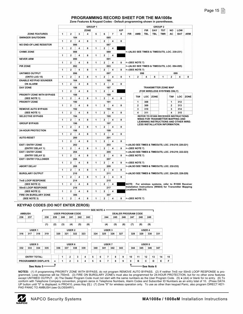
Page 15 PROGRAMMING RECORD SHEET FOR THE MA1008e
Zone Features & Keypad Codes - Default programming shown in parentheses.
GROUP 1 GROUP 2 ZONE K/P FIR DAY TST NO LOW
ZONE FEATURES 1 2 3 4 5 6 7 8 FIR AMB TBL TBL TMR AC BAT ARM SWINGER SHUTDOWN 184 085 1 2 4 8 1 2 4 8 NO END-OF-LINE RESISTOR 086 087 1 2 4 8 1 2 4 8 CHIME ZONE 088 089 <--(ALSO SEE TIMES & TIMEOUTS, LOC. 230-231) 1 2 4 8 1 2 4 8 NEVER ARM 090 091 1 2 4 8 1 2 4 8 <--(SEE NOTE 7) PIR ZONE 092 093 <--(ALSO SEE TIMES & TIMEOUTS, LOC. 094-095) 1 2 4 8 1 2 4 8 <--(SEE NOTE 7) UNTIMED OUTPUT 096 097 098 099
(ONTO LUG 15) 1 2 4 8 1 2 4 8 1 2 4 8 1 2 4 8 ENABLE KEYPAD SOUNDER 164 165
ON ALARM 1 2 4 8 1 2 4 8 DAY ZONE 186 187 TRANSMITTER ZONE MAP
1 2 4 8 1 2 4 8 (FOR WIRELESS SYSTEMS ONLY) PRIORITY ZONE WITH BYPASS 188 189
TX# LOC ZONE
TX# LOC ZONE (SEE NOTE 1) 1 2 4 8 1 2 4 8 PRIORITY ZONE 190 191 1 308 1 312
1 2 4 8 1 2 4 8 2 309 2 313 REMOVE AUTO BYPASS 192 193 3 310 3 314
(SEE NOTE 1) 1 2 4 8 1 2 4 8 4 311 4 315 SELECTIVE BYPASS 194 195 REFER TO R1000 RECEIVER INSTRUCTIONS
WI604 FOR TRANSMITTER MAPPING AND LEARNING INSTRUCTIONS AND OTHER WIRE-LESS INSTALLATION INFORMATION.
1 2 4 8 1 2 4 8 GROUP BYPASS 196 197
1 2 4 8 1 2 4 8 24-HOUR PROTECTION 198 199
1 2 4 8 1 2 4 8 AUTO-RESET 200 201
1 2 4 8 1 2 4 8 EXIT / ENTRY ZONE 202 203 <--(ALSO SEE TIMES & TIMEOUTS, LOC. 218-219; 220-221)
(ENTRY DELAY 1) 1 2 4 8 1 2 4 8 <--(SEE NOTE 7) EXIT / ENTRY ZONE 204 205 <--(ALSO SEE TIMES & TIMEOUTS, LOC. 218-219; 222-223)
(ENTRY DELAY 2) 1 2 4 8 1 2 4 8 <--(SEE NOTE 7) EXIT / ENTRY FOLLOWER 206 207
1 2 4 8 1 2 4 8 <--(SEE NOTE 7) ABORT DELAY 208 209 <--(ALSO SEE TIMES & TIMEOUTS, LOC. 232-233)
1 2 4 8 1 2 4 8 BURGLARY OUTPUT 210 211 <--(ALSO SEE TIMES & TIMEOUTS, LOC. 224-225; 228-229)
1 2 4 8 1 2 4 8 7mS LOOP RESPONSE 214 215
(SEE NOTE 2) 1 2 4 8 1 2 4 8 50mS LOOP RESPONSE 216 217
(SEE NOTE 2) 1 2 4 8 1 2 4 8 FIRE ON BURGLARY ZONE 306 307
(SEE NOTE 3) 1 2 4 8 1 2 4 8 <--(SEE NOTE 7)
NOTE: For wireless systems, refer to R1000 Receiver Installation Instructions (WI604) for Transmitter Mapping Locations 308-315.
KEYPAD CODES (DO NOT ENTER ZEROS) SEE NOTE 4
AMBUSH USER PROGRAM CODE DEALER PROGRAM CODE 236 237 238 239 240 241 242 243 244 245 246 247 248 249
(1) (2) (3) (4) (5) (6) (4) (5) (6) (7) (8) (9)
USER 1 USER 2 USER 3 316 317 318 319 320 321 322 323 324 325 326 327
USER 5 USER 6 332 333 334 335 336 337 338 339 340 341 342 343
USER 7
USER 4 328 329 330 331
USER 8 344 345 346 347
ENTRY TOTAL: 2 3 4 5 6 7 8 9 10 11 12 13 14 15
PROGRAMMER DISPLAYS 2 3 4 5 6 7 8 9 0 B C D E F
1
1
See Note 5 See Note 6
NOTES: (1) If programming PRIORITY ZONE WITH BYPASS, do not program REMOVE AUTO BYPASS. (2) If neither 7mS nor 50mS LOOP RESPONSE is pro-grammed, Loop response will be 750mS. (3) FIRE ON BURGLARY ZONE's must also be programmed for 24-HOUR PROTECTION, but for no other zone features except UNTIMED OUTPUT. (4) The Dealer Program Code must not start with the same numbers as the User Program Code. (5) (dot) or blank for no entry. (6) To conform with Telephone Company convention, program zeros in Telephone Numbers, Alarm Codes and Subscriber ID Numbers as an entry total of 10. (Press DATA UP button until "0" is displayed; in PRO410, press Key [0].) (7) Zone "8" for wireless operation only. To use as other than keypad Panic, also program DIRECT KEY-PAD PANIC TO AMBUSH (see GLOSSARY).
MA1008e / 1008eM Installation Instructions L NAPCO Security Systems
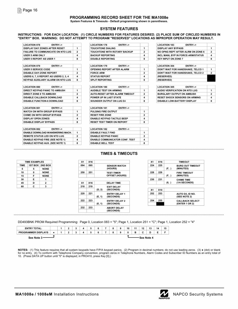
Page 16 PROGRAMMING RECORD SHEET FOR THE MA1008e System Features & Timeouts - Default programming shown in parentheses.
TIME EXAMPLES X1 X16 X1 X16 TIMEOUT TIME 1ST BOX 2ND BOX 094 095 SENSOR WATCH
(HOURS) 224 225 BURG OUT TIMEOUT
(F, ) (MINUTES) 5 5 NONE 10 0 NONE 250 251 TEST-TIMER
OFFSET (HOURS) 228 229 FIRE TIMEOUT
(F, ) (MINUTES) 15 F NONE 30 E 1 230 231 CHIME TIME
(8, ) (1/4 SECONDS) 45 D 2 X1 X16 DELAY TIME 60 C 3 218 219 EXIT DELAY
(D, 2) (SECONDS)
X1 X10 220 221 ENTRY DELAY 1
(E, 1) (SECONDS) 252 253 AUTO D/L ID NO.
(SEE NOTE 2) 222 223 ENTRY DELAY 2
(E, 1) (SECONDS) 254 255
232 233 ABORT DELAY
(SECONDS)
CALLBACK SELECT (ENTER 1 OR 2)
ENTRY TOTAL: 2 3 4 5 6 7 8 9 10 11 12 13 14 15
PROGRAMMER DISPLAYS 2 3 4 5 6 7 8 9 0 B C D E F
1
1
See Note 3 See Note 4
NOTES: (1) This feature requires that all system keypads have F/P/A keypad panics. (2) Program in decimal numbers; do not use leading zeros. (3) (dot) or blank for no entry. (4) To conform with Telephone Company convention, program zeros in Telephone Numbers, Alarm Codes and Subscriber ID Numbers as an entry total of 10. (Press DATA UP button until "0" is displayed; in PRO410, press Key [0].)
LOCATION 078 ENTRY--> LOCATION 178 ENTRY--> LOCATION 183 ENTRY--> DISPLAY DAY ZONES AFTER RESET 1 TOUCHTONE DIALING 1 DISPLAY ANY BYPASS 1 FAILURE TO COMMUNICATE ON NTO LUG 2 TOUCHTONE WITH ROTARY BACKUP 2 NO OPNG REPT AFTER ALRM ON ZONE 6 2 USER 5 ARM ONLY 4 BACKUP REPORTING 4 INCL MANL BYP IN FORCE-ARM/STATUS 4 USER 5 REPORT AS USER 1 8 DOUBLE REPORTING 8 KEY INPUT ON ZONE 7 8 LOCATION 079 ENTRY--> LOCATION 179 ENTRY--> LOCATION 304 ENTRY--> USER 5 SERVICE CODE 1 OPENING REPORT AFTER ALARM 1 DON'T WAIT FOR HANDSHAKE, TELCO 1 1 DISABLE DAY-ZONE REPORT 2 FORCE ARM 2 DON'T WAIT FOR HANDSHAKE, TELCO 2 2 USERS 6, 7, 8 REPORT AS USERS 2, 3, 4 4 STATUS REPORT 4 (RESERVED) 4 KEYPAD AUXILIARY ALARM ON NTO LUG 8 SPLIT REPORTING 8 (RESERVED) 8 LOCATION 080 ENTRY--> LOCATION 180 ENTRY--> LOCATION 305 ENTRY--> DIRECT KEYPAD PANIC TO AMBUSH 1 AUDIBLE TEST ON ARMING 1 AUDIO VERIFICATION ON NTO LUG 1 DIRECT ZONE 8 TO AMBUSH 2 AUTO-RESET AFTER ALARM TIMEOUT 2 BURGLARY OUTPUT ON AMBUSH 2 DISABLE CALLBACK DOWNLOAD 4 POWER UP IN LAST STATE 4 RESET SHOCK SENSORS ON ARMING 4 DISABLE FUNCTION-6 DOWNLOAD 8 SOUNDER OUTPUT ON LUG E4 8 DISABLE LOW-BATTERY DISPLAY 8 LOCATION 081 ENTRY--> LOCATION 181 ENTRY--> WATCH ON WITH GROUP BYPASS 1 PULSING FIRE OUTPUT 1 CHIME ON WITH GROUP BYPASS 2 RESET FIRE ZONE 2 DISPLAY OPEN ZONES 4 ENABLE KEYPAD TACTILE BEEP 4 DISABLE DISPLAY BYPASS 8 RESET TEST TIMER ON REPORT 8 LOCATION 082 ENTRY--> LOCATION 182 ENTRY--> ENABLE DOWNLOAD W/ANSWERING MACH. 1 DISABLE FAULT FIND 1 REMOTE STATUS LED ON NTO LUG 2 ENABLE KEYPAD PANIC 2 ENABLE KEYPAD FIRE (SEE NOTE 1) 4 ENABLE COMMUNICATOR CONF. TEST 4 ENABLE KEYPAD AUX. (SEE NOTE 1) 8 DISABLE BELL TEST 8
SYSTEM FEATURES
INSTRUCTIONS: FOR EACH LOCATION: (1) CIRCLE NUMBERS FOR FEATURES DESIRED. (2) PLACE SUM OF CIRCLED NUMBERS IN "ENTRY" BOX. WARNING: DO NOT ATTEMPT TO PROGRAM "RESERVED" LOCATIONS AS IMPROPER OPERATION MAY RESULT.
TIMES & TIMEOUTS
DD493BNK PROM Required Programming: Page 0, Location 083 = "5"; Page 1, Location 251 = "C"; Page 1, Location 252 = "4"
MA1008e / 1008eM Installation Instructions L NAPCO Security Systems
Page 17
Abort Delay (Locations 208, 209; 232, 233) A delay period that allows cancellation of the central sta-
tion report. This is done by disarming the panel within the delay period. Program Locations 208-209 for zone selection; Locations 232, 233 for delay time (see Time Selection). The NTO Lug E15 will be subject to the abort delay if Untimed Output and Abort Delay are programmed for the same zone. Note: If Abort Delay is selected for a 24-Hour Zone or a Zone-Restore Zone, the cause of the alarm must be corrected before disarming the panel.
AC-Failure Reporting (Locations 169;173) If AC is removed from the panel, the first three LED's will
flash slowly and a "1" will be displayed (while armed or dis-armed). If disarmed, holding down Key [9] will reset the indi-cation for about three minutes to permit arming. However, the failure indication will return within a few minutes, whether armed or disarmed, unless AC power is restored. If pro-grammed for Report on Alarm, the report will be delayed for 1 hour. Restores report immediately.
Access Number for Outside Line (Locations 115, 147) Some subscribers will have a telephone system that re-
quires one digit to access an outside line before the telephone number can be dialed. Also, the first dial tone encountered (prior to the access number) may have a frequency that is different from that of the accessed dial tone (440Hz). One or more 4-second Pre-Dial Delay "D"s may be entered before the access number instead of a dial tone with frequency "E". See Pre-Dial Delay.
If your subscriber's system uses an access number: 1. Contact the telephone-equipment supplier to find out if a
dial tone other than 440Hz is received prior to dialing the access number. If the communicator must delay before dialing the access number instead of attempting to rec-ognize the dial tone, find out how many 4-second delays must be programmed.
2. For Telephone 1, (a) enter the Dial-Tone Detection "E" or Pre-Dial Delay "D" in Location 114. Enter any extra "D" that may be required starting in Location 115; (b) enter the access number digit in Location 115, or the first available location thereafter; (c) starting in the first available location after the access number, enter any Pre-Dial Delay "D"s needed before the second dial tone; the Dial Tone Detection "E" for the second dial-tone fre-
quency; then the telephone number. 3. If Telephone 2 is used, repeat step 2 starting in location
146. (See Backup Reporting; Double Reporting; and Split Reporting). Also see Dial-Tone Detection; Pre-Dial Delay.
Alarm Codes See Report on Alarm
Alarm History Hold-Down Key [B] will display (on the digital readout) all
alarm conditions that have occurred. While holding down Key [B], note the number(s) displayed indicating the zone(s) vio-lated. When the system is rearmed, the previous alarm his-tory will stay memorized until automatically erased by a new alarm condition. Note that Alarm History will not display Fire, Fire Trouble, Ambush, or zones directed to Ambush, but it will display Fire on Burg Zone alarms.
Alarm Outputs (Locations 181, 210-211; 224-225; 228-229; Terminals 3, 4; NTO Lug E15)
The MA1008e has a common Burglary/Fire siren output at Terminals 3 and 4. Steady bell and pulsing bell outputs for Burglary and Fire, respectively, are selectable options. Table 4 summarizes wiring and programming for signaling an alarm in typical installations. Refer to Time Selection for timeout durations.
Ambush Code (Locations 236, 237) Burglary Output on Ambush (Location 305)
A 1- or 2-digit code that is entered by the user prior to disarming to access the Ambush Zone, causing a silent report to be sent to a central station. Thus, should a user be forced to disarm by an assailant, he can silently signal an emergency while appearing to be merely disarming the system. The Arm/Disarm Code must be entered less than 10 seconds af-ter the Ambush Code for an ambush report to be transmitted. The Ambush Zone will automatically report when pro-grammed to report on alarm.
To program the ambush feature, (a) program Ambush to Report on Alarm (enter a "2" in Location 168); (b) enter 1 or 2 digits as the Ambush Code In Locations 236-237; (c) enter an Ambush alarm report code in Locations 018-019.
Inform the user what the Ambush Code is, and that his arm/disarm code must be entered less than 10 seconds after the Ambush Code for an ambush report to be sent.
Burglary Output on Ambush may be programmed in
5. GLOSSARY & PROGRAMMING DATA
Output Wiring Output Locations Timeout Locations Remarks Sweep Siren Speaker on 3 (+) & 4 (–) 210, 211 224, 225 –
Fire (Steady) Siren Speaker on 3 (+) & 4 (–) – 228, 229 Fire Zones only
Fire (Pulsing) Siren Speaker on 3 (+) & 4 (–) "1" in location 181 228, 229 Fire Zones only
Steady Bell Bell on 3 (+) & 4 (–) 210, 211 224, 225 Cut Jumper E
Pulsing Bell Bell on 3 (+) & 4 (–) "1" in location 181 228, 229 Fire Zones only; cut Jumper E
Untimed Output (NTO) E15 (–) & 5 (+) 096-999 – <300mA for strobes, etc. See NTO.
Note: (1) For UL Residential Fire installations, use a bell on Terminals 3 (+) and 4 (-); cut Jumpers E and PS and install Jumper J2 (see Wiring Diagram). See Time Selection for timeouts. (2) Cut Jumper to prevent the fire signal from sounding a steady siren (or bell, if Jumper E is cut). (3) Cut Jumper D to produce an alternating two-tone siren sound.
Table 4. Alarm Outputs
Temporal Fire Bell on 3(+) & 4 (–) "C" in location 175 – Provides supervised Bell Output
MA1008e / 1008eM Installation Instructions L NAPCO Security Systems
Page 18
conjunction with either Direct Zone 8 to Ambush or Direct Key-pad Panic to Ambush to sound are audible alarm when am-bush is tripped. Also see Direct Keypad Panic to Ambush; Di-rect Zone 8 to Ambush.
Anti-Jam Time If the communicator does not detect a dial tone within 12
seconds, the Anti-Jam feature will be activated. That is, the communicator will go off-line for a 15-second anti-jam interval in order to free the telephone circuit from incoming calls, then make another 12-second attempt at dial-tone detection. If still unsuccessful, the communicator will again go off-line for 15 seconds, then proceed to dial anyway.
To test the Anti-jam feature, call the alarm phone line from a different phone line, then activate an alarm. The incoming call should be disconnected by the control panel.
Arm Lug (Lug E4) Lug E4 (ARM) will go to approximately 1Vdc when the sys-
tem is armed. This lug may be used for auxiliary equipment. For use, refer to the instructions furnished with the peripheral device. Also see Sounder Output On Lug E4.
Audible Test on Arming (Location 180) (Required for UL Mercantile installations). To test the alarm
circuit each time the system is armed, add a "1" to Location 180. The alarm is then activated briefly about 8 seconds after the panel is armed. If the alarm does not sound, the device may be defective.
Audio Verification on NTO Lug See Untimed Output
Auto-Bypass Zone See Remove Auto-Bypass
Auto-Download ID Number (Locations 252, 253) Callback Select (Location 254)
Napco PCD2000 Software Version 2.E and later includes a PC-Preset utility wherein numerous programs may be preset for automatic remote uploading or downloading from the instal-lation site while the computer is unattended (in standby mode). The Auto-Download ID Number identifies the program in the computer that will be selected. (Note that the Dealer Program Code in the PCD2000 must agree with that of the control panel for the remote connection to be established).
At the installation site, program the Auto-Download ID Number in Locations 252 and 253, in decimal numbers, corre-sponding to that in the computer. Also program the Callback Telephone Number of the computer. If two phone numbers are programmed, select the phone to be called in Location 254. Then, arm the panel, disarm and, within five seconds, access Function 5 to execute an Auto-Download.
Auto-Reset (Location 200-201) Auto-Reset After Alarm Timeout (Location 180)
If a zone signals an alarm and is selected for Auto-Reset, it will automatically rearm itself soon after the alarm condition is removed. Auto-Reset may be delayed to occur after the time-out period by programming a "2" in Location 180.
Zones 1--8/Panic that are not programmed for Auto-Reset will not be capable of signaling another alarm until (a) the cause of the alarm has been removed and (b) the panel is dis-armed.
Also see Swinger Shutdown.
Backup Reporting (Location 178) When Backup Reporting is selected and the communicator
does not reach the first telephone number after two attempts, seven attempts will be made to reach the second telephone number. Enter Subscriber Identification Numbers for Tele-phone 2 (Locations 132-143) and other information required for Telephone 2 (Locations 144-163). If Double Reporting is selected with Backup Reporting, all reports sent to the first tele-phone number will also be transmitted to the second telephone number. However, if the first transmission fails, two reports will be sent to Telephone 2 (Double Reporting). Note: Subscriber Identification Numbers for both Telephones 1 and 2 must be entered, even if they are the same.
Battery 12VDC standby power source in the control panel to pro-
vide backup protection in the event of a power loss. The 4AH battery is supplied; the 7AH is available as an option. Note that the battery is an integral part of the system. It must be installed, even if AC power is present.
Battery Lug (Lug E14) This is a fused battery output (3A) designed primarily for
use with the MVA-1000 Talking Siren Driver.
Burg Lug (Lug E14) Lug E10 (BURG) will go to about 1VDC when a burglary
alarm is tripped. E10 may be used to trip an LW-900 Long-Range Wireless interface. Or, a relay (400Ω minimum) may be connected between E10 and Terminal 5 (+ AUX. POWER) if a diode is wired in series (cathode to E10; anode to relay coil).
Burglary Output See Alarm Outputs
Burglary Output on Ambush See Ambush Code
Callback Telephone Number 1 (Locations 270-285; PROM Page-1 Locations 014-029)
Callback Telephone Number 2 (Locations 286-301, PROM Page-1 Locations 030-045)
Number of Rings (Location 269; PROM Page-1 Location 013)
The control panel will call back the PCI2000 as a security check prior to downloading when using the Callback Method. Provisions for two callback telephone numbers are made for the Auto-Download Mode. Program at least one callback number starting in Location 270. (Remember that a "D" or an "E" must be programmed before the telephone number - see Telephone Numbers). The panel will initiate the callback after waiting 15 rings, unless programmed otherwise. To change the number of rings before callback, enter the desired number of rings (3 minimum, 15 maximum) in Location 269. Also see Auto-Download ID Number.
Chime Zone (Location 088-089) Chime On with Group Bypass See Group Bypass
This annunciator feature may be programmed for any zone to sound at the keypad while disarmed when the zone goes into trouble. Hold down Key [5] until the function beep sounds to enable or disable the Chime. Chime duration is program-mable (Locations 230, 231) in units of 1/4 seconds. See Time Selection. The Chime-Zone number will be displayed for the duration of the programmed chime time, or for as long as the zone is open (or shorted), whichever is greater. Also see Never-Arm Zone. Note: A "1" in Location 230 will prevent the sounder from coming on.
MA1008e / 1008eM Installation Instructions L NAPCO Security Systems
Page 19
Closing Report (Select User(s) Closing) (Location 174) Force Arm Report (Locations 179; 038-039) Status Report (Locations 179; 000-029; 038-039) Include Manual Bypass in Force-Arm/Status Report
(Location 183) On arming, the communicator can transmit a closing
code for each user, a Force-Arm Code, and a Status Re-port that identifies the problem zone to the central station. Note that Subscriber Identification Numbers (Locations 108-111; 140-143) and Closing Codes (Locations 030-037) must be entered for any closing report. Program closing report (Select User(s) Closing, Location 174) to report each time the panel is armed. Each of up to four users may have his own Closing Code (Locations 030-037).
Select Force Arm Report ("2" in Location 179) to report only when arming with an auto-bypassed zone. This trans-mission will consist of a Closing Code followed by a Force-Arm Code. Select both closing report and Force Arm to always send a closing report, and a Force Arm report only if one or more zones were auto-bypassed. Also see Prior-ity Zone with Bypass.
Select Status Report ("4" in Location 179) to send a Force Arm report followed by a Status Report that identifies the auto-bypassed zone(s). The second Alarm-Code loca-tion is usually used for this purpose. If this location is va-cant, the first location will be used.
To include manual bypasses in a Force Arm/Status Re-port, program a "4" in Location 183. (Either Force Arm or Status Report must also be programmed).
Following is an example of a typical Force-Arm/Status Report.
Example. A burglar breaks into a commercial establish-ment during the night, breaking the window foil. The Alarm Subscriber Identification Number is '"123"; the Alarm Code is "1" (Burglary Zone 1); the Opening/Closing Subscriber Identification Number is "456"; the Force-Arm Code is "F"; the Closing Code for User 1 is "C". The communicator will send the following report to the central station (single-digit data format):
1231 - Sent when alarm occurs. 456B - Opening; User returned and inspected damage. 456C - Closing. CCC1 - User 1 rearmed. 456F - Force Arm. FFF1 - Zone status at time of closing: Window foil still
broken. Zone 1 auto-bypasses; repair required.
Control-Panel Restore See Restore Report
Data Format (Locations 113,145) Consult the central station to find out which of the fol-
lowing formats to use. Extended Format. Extended-format reporting allows
the communicator to transmit an extra digit to the central station. This extra digit is generally used to report the user or the zone on which the event occurred.
Example. An installation uses the following pro-grammed transmission information: Subscriber Identifica-tion Number is ;"678"; a Closing Report is selected for User 3; Extended Format Closing Code is "C3" (Closing, User 3). If User 3 closes, the communicator will transmit:
678C - Subscriber "678" has closed. CCC3 - Closing, User 3.
Extended Format may be used with most central-station receivers. Most receivers capable of recognizing multiple reporting will also recognize Extended Format. The central station will indicate the event codes to be programmed. Extended Format does not require any programming in Lo-cations 113 and 145. To use Extended Format, follow Steps 2 through 5 of Two-Digit Event Code Format later in this section.
Single-Digit Event Code Format. If the receiver can-not accept extended reporting,
1. Program a "1" in Location 113 (and 145 for a second telephone number, if used). See Double Reporting and Backup Reporting.
2. Enter the first digit for any Alarm/Trouble Code, Re-store Code and Opening/Closing Codes.
Note: If it is desired to have a Single-Digit Event Code for one telephone number and Extended Format for the other, program both digits for all event codes. Use the first digit to indicate the alarm type and the second digit to indi-cate the zone. The telephone number with a "1" in Loca-tion 113 (or 145) will transmit only the first digit. The other telephone number will use both digits. (Single-Digit Format will ignore the second digit of the event code).
Two-Digit Event Code Format. Some central-station receivers require that a two-digit code be sent in each re-port.
Example. In a certain installation, the Alarm Subscriber Number is "123"; a burglar alarm occurs on Zone 1 (Alarm Code "31"). The communicator will send "12331".
To use Two-Digit Event Code Format, 1. Program a "2" in Location 113 (145 for a second tele-
phone number, if used). See Double Reporting and Backup Reporting.
2. Enter an Alarm Code (Locations 000-029) for each zone or condition to report on alarm (see Report on Alarm) or for a Force-Arm/Status Report as follows: a. Enter the first digit of the Alarm Code. (This digit
may be used to indicate alarm type.) b. Enter the second digit of the Alarm Code. (This
digit may be used to indicate the zone.) 3. Repeat Step 2 to enter Restore Codes (Locations
040-069) for each zone selected for Control-Panel Restore or Zone Restore (see Restore Report).
4. If Opening Report or Opening Report After Alarm is selected, enter a two-digit Opening Code for each user (Locations 070-077). See Opening Report; Opening Report After Alarm.
5. If Closing Report is selected, enter a two-digit Closing Code (Locations 030-037) for each user. If a Force Arm or Force-Arm/Status Report is selected, also en-ter a two-digit Force-Arm Code (Locations 038, 039).
Note: Single-Digit Format will override Two-Digit For-mat in Locations 113 and 145 if both are pro-grammed.
Sum-Check Format. Sum Check is a sophisticated data format used to enhance the speed and check the ac-curacy of the received transmission. This format should be preferred if the central station is capable of receiving it.
After transmitting the Subscriber identification Number and the event code, the communicator sends a verifying digit that is the sum of both. The receiver compares the
MA1008e / 1008eM Installation Instructions L NAPCO Security Systems
Page 20 verifying digit with the sum of the other two numbers to check transmission accuracy. To select Sum Check, program a "4" in Location 113 (or 145 for a second telephone number, if used).
Day Zone (Locations 186, 187) Disable Day-Zone Report See PIR Zone Display Day Zones After Reset (Location 078)
A Day Zone is a Burglary Zone that will cause visual and audible indication at the keypad if the loop has an open condi-tion only when disarmed. This feature may be used to warn of trouble during the day, when the control panel is not armed. If the Day Zone experiences a problem (a break in a window foil, for example), the green STATUS LED on the keypad will flash, the sounder will beep repeatedly, and the display will indicate the problem zone(s). Hold down Key [9] to silence the sounder and clear the display. Arm and disarm the panel to reset the Day Zone.
If a "1" is programmed in Location 078 (Display Day Zones After Reset), the Day-Zone number(s) will continue to display after the sounder is silenced until the condition is corrected, and the Day Zone will auto-reset without the need to arm/disarm.
Note: For high security Day-Zone supervision, also pro-gram Disable Fault Find (enabling Fault Find will disable Day-Zone supervision).
Also see Watch On with Group Bypass.
Dealer Program Code (Locations 244-249) This code is required to enter the Dealer Program Mode.
The default Dealer Program Code is 4,5,6,7,8,9, however this code must be changed to preserve system security. Repro-gram the 3- to 6-digit Dealer Program Code starting in location 244. Note: (1) The Dealer Program Code must not start with the same numbers as the User Program Code. (2) The Dealer Program Code also serves as your Download Security Code.
Dial-Tone Detection (Locations 116,148) At least one Dial-Tone Detection entry is usually required
for each telephone number used to ensure that a dial tone is present before the communicator dials.
When an "E" is programmed before the first digit of an out-side telephone number, the communicator dial-tone detection circuit is set to detect the standard 440Hz dial tone. The "E" is generally entered in Location 116 for Telephone 1 and Loca-tion 148 for Telephone 2, if used.
It may be necessary to program at least one 4-second Pre-Dial Delay before a Dial Tone Detection "E". With certain non-standard exchanges, Pre-Dial Delay "D"s may be used with-out a Dial-Detection "E". (See Access Number for Outside Line; Pre-Dial Delay).
Direct Keypad Panic to Ambush (Location 080) Direct Zone 8 to Ambush (Location 080)
Program Direct Keypad Panic to Ambush ("1" in Location 080) to free Zone 8 for wireless use while providing silent panic. Or, select Direct Zone 8 to Ambush ("2" in Location 080) to have wireless transmitters that are mapped to Zone 8 send a silent report. (These will report using the Ambush Code).
Disable Bell Test (Location 182) Program an "8" in Location 182 to prevent unauthorized
persons from sounding the bell.
Disable Callback-Method Download (Location 080) Data may be remotely downloaded to an MA1008e using
Napco Quickloader™ software and interface if the correct download security code is known. Program this feature to prevent downloading to an unattended panel.
Disable Day-Zone Report See PIR Zone
Disable Display Bypass (Location 081) For added security, this feature disables Hold-Down Func-
tion 2 and the BYPASS LED after exit delay expires.
Disable Fault Find (Location 182) When the Fault-Find mode is accessed (Hold-Dawn Key
[7]), two things occur: (a) the loop response of all zones is pre-set to 7mS (fastest loop response), and (b) securing a zone in trouble will cause the sounder to beep for about 2 seconds. This set of conditions aids bath installer and user. The in-staller, tapping and poking at suspect points, can easily locate swingers by listening for the beep. Similarly, the user can confirm the repair of a zone in trouble by listening for the beep and thus eliminate the need of returning to the keypad to visu-ally check after each attempt.
Hold dawn Reset Key [9] to restore normal operation. Arming the system successfully will automatically cancel the Fault-Find mode. Program a "1" in Location 182 to prevent unauthorized use of the Fault-Find mode.
Disable Function-6 Download (Location 080) An "8" in Location 080 will prevent manual remote
downloading at the panel. See Manual Download.
Disable Low-Battery Display See Low Battery
Display Any Bypass (Location 183) Hold-Down Function 2 (Display Bypass) normally displays
manually-bypassed zones only, when Display Any Bypass is selected and a zone is auto-bypassed, the yellow BYPASS LED will light, and Hold-Down Function 2 will display Auto-Bypassed and Priority bypassed Zones as well.
Display Day Zones After Reset See Day Zone
Display Open Zones (Location 081) A "4" in Location 081 will cause any non-24-Hour zone that
is open (or shorted) while disarmed to automatically display at the keypad in addition to the flashing green LED.
Don't Wait for Handshake, Telco 1 (Location 304) Don't Wait for Handshake, Telco 2 (Location 304)
Select this feature for telephones not reporting to a central station. (This feature may be useful for demo purposes).
Double Reporting (Location 178) When Double Reporting is selected, only information that
is successfully sent to Telephone 1 will be sent to Telephone 2 as well. To program, enter an "8" in Location 178. Enter Subscriber Identification Numbers for Telephone 2 (Locations 132-143) and related information required for Telephone 2 (Locations 144-163).
If Backup Reporting is selected with Double Reporting, reports sent to the first telephone number will also be sent to the second. However, if the first transmission fails, two re-ports will be sent to Telephone 2. Split Reporting will override Double Reporting if both are programmed.
Note: Subscriber Identification Numbers for Telephones 1 and 2 must be entered, even if they are the same.
"E" Lugs see INDEX
MA1008e / 1008eM Installation Instructions L NAPCO Security Systems
Page 21
Enable Communicator-Confidence Test (Location 182) Program a "4" in Location 182 to enable the Communica-
tor-Confidence Test. This feature checks the telephone line for the presence of a dial tone only in those systems that are programmed to communicate with a central station. Note: Do not arm and disarm the panel just before making this test.
Hold down Key [6] until the sounder starts to pulse. If the line is okay, the pulsing will stop; if not, a steady tone will sound (check phone lines). To silence, hold down Key [9].
Enable Download with Answering Machine (Location 082) Permits downloading to a telephone with an answering
machine (factory programmed). After one ring, the panel will listen for the modem tone produced by the PCI2000. If rec-ognized, the panel will go into line seizure and, if security codes match, establish connection with the PCI2000.
Enable Keypad Auxiliary Panic (Location 082) This feature may be enabled only if all system keypads
are F/P/A-panic compatible. (Cut panic-enabling jumpers in all keypads). Pressing the [B/A] and [#] keys simultaneously will activate Keypad Auxiliary Panic. This is a "report only" feature. Program an Alarm Code in Locations 062-063 and a Group-2 Subscriber ID Number. A successful report will be indicated by a ringback at the keypad. In order to prevent multiple alarms from being transmitted, subsequent Auxiliary-Panic alarms cannot be tripped for five minutes. Also see Keypad Aux. Alarm on NTO Lug.
Enable Keypad Fire Panic (Location 082) This feature may be enabled only if all keypads in the sys-
tem have the F/P/A-panic capability. (Cut panic-enabling jumpers in all keypads). Pressing the [9/F] and [#] keys si-multaneously will activate Keypad Fire Panic.
Enable Keypad (Police) Panic See Panic Zone
Enable Keypad Sounder on Alarm (Locations 164-165) Programmable for Zones 1-7 and Keypad Panic. When
tripped, a steady tone will sound at the keypad until the panel is disarmed.
Enable Keypad Tactile Beep (Location 181) Causes the sounder to beep briefly with each press of a
button. For RP1000LCD and RP1000eLCD keypads: Cut the keypad tactile-beep jumper to prevent a double beep from sounding.
Exit/Entry Delay (Locations 218-223) Permits exit and entry through the Exit/Entry Zone(s) (see
Locations 202-205) after the system is armed without setting off an immediate alarm. Exit delay allows the user to leave the premises after the panel has been armed. Entry delay allows the user time to enter and disarm the panel. Upon entering, the keypad sounder will emit a steady tone to re-mind the user to disarm.
Two separately-programmable entry delays are provided to accommodate different entry zones (only one exit delay is provided). If two or more Exit/Entry Zones are entered in succession, the delay programmed for the last Exit/Entry Zone entered will take precedence over all others.
Exit time (Locations 218-219) and entry time (Locations 220-223) may each be programmed for up to 255 seconds (4¼ minutes). See Time Selection. If times are not pro-grammed, exit time will be 60 seconds; entry delay will be 30 seconds. (In UL installations, exit time may not exceed 60
seconds; entry time may not exceed 45 seconds). Entry delay may be cancelled by holding down Key [4]
(Instant Protection) prior to or after arming, however it will be automatically reinstated upon disarming.
Exit Entry Follower (Locations 206, 207) A zone programmed as an Exit/Entry Follower will ignore
detection during the exit delay, and only during entry delay if the Exit/Entry Zone is entered first. Thus, detection devices (passive infrared detectors, for example) along the path be-tween the keypad and the exit/entry door will not signal an alarm during exit/entry delay under normal conditions. How-ever, if a device in the Exit/Entry Follower Zone detects a vio-lation when the exit/entry door has not first been entered, there will be no entry delay and the Exit/Entry Follower Zone will go into an instant alarm.
If the panel is armed with the entry delays cancelled (Instant Protection), any violation on the Exit/Entry Zone or the Exit/Entry Follower Zone will cause an immediate alarm.
Extended Format See Data Format
Failure to Communicate on NTO Lug See Untimed Output
Fault Find See Disable Fault Find
Fire Lug (Lug E9) Lug E9 (FIRE) will go to about 1VDC when a fire alarm is
tripped. E9 may be used to trip an LW-900 Long-Range Wireless Interface. Or, a relay (400Ω minimum) may be con-nected between E9 and Terminal 5 (+ AUX. POWER) if a diode is wired in series (cathode to E9; anode to relay coil).
Fire Zone (Terminals 11 & 12) Fire on Burg Zone (Locations 306-307)
(Note: Do not use Fire Zones in Mercantile installations). The Fire Zone is indicated by the red FIRE/TROUBLE key-pad LED. Normally-open devices are connected across Ter-minals 11 and 12, in parallel with the 2200Ω end-of-line resis-tor (see Wiring Diagram). A short across the Fire Zone will cause a fire alarm: the red LED will light and the sounder will pulse; an open circuit (trouble) will cause a blinking red LED and a pulsing sounder after a 10-second delay. The sounder may be silenced using Reset Key [9]. The LED will go off within 30 seconds after reset if the alarm or trouble is cleared. Note: Even if the Fire Zone is not used, the end-of-line resis-tor must be installed.
For the Fire Zone to report on alarm (Location 168) or to restore (Location 172), program Alarm Codes in Locations 016-017 and Restore Codes in Locations 056-057. Trouble and Restore Trouble on all Fire Zones (including Fire on Burg Zones, see below) are reported in Locations 020-021 and 060-061, respectively. To reset Fire, program a "2" in Loca-tion 181 (see Reset Fire Zone).
Any Zone 1-7 may be converted to a Fire Zone by pro-gramming it for Fire on Burg Zone, however that zone must be programmed for 24-Hour Protection as well. No other zone feature except Untimed Output may be selected for that zone, however program reporting features as required; Fire alarms will activate a steady siren unless Pulsing Fire Output is programmed. Note: Only 4-wire smokes may be used on zones programmed as Fire on Burg Zone.
When an alarm condition is detected on any Fire Zone, a Fire Alarm Verification feature will cause all zones to power down for 10 seconds. Power is restored and a 4-second
MA1008e / 1008eM Installation Instructions L NAPCO Security Systems
Page 22
power-up time is started. Thereafter, the zone will be active again. This represents a total processing time of 14 seconds from the time the alarm is first detected. If an alarm condition still exists or reoccurs within 2 minutes, an alarm will be initi-ated, otherwise the zone will return to its original state. Note: Alarm restores are sent individually; trouble restores are not sent until all fire troubles are restored.
Force-Arm Report See Closing Report Ground-Start Module, GSM-400 (Lug E3)
If the dial tone is not continuously active, Ground-Start Module Model GSM-400 will be required at Lug E3 to estab-lish the dial tone. For installation, refer to the instructions fur-nished with the GSM-400.
Group Bypass (Location 196, 197) Chime On with Group Bypass (Location 081)
Group Bypass removes a programmed group of zones from the system. It is often used to deactivate some or all in-terior zones simultaneously so that the user may move freely throughout the premises but still be protected from intrusion through armed perimeter zones.
Group Bypass is executed by pressing Key [B] twice; the yellow BYPASS LED on the keypad will light. When the panel is subsequently disarmed, all bypassed zones automatically revert to non-bypassed zones. The zones bypassed may be checked by holding down Key [2] (Display Bypass) until the beep sounds and all zones have been displayed.
When a "1" is entered in Location 081 (Watch On with Group Bypass), all Day Zones will be activated simultaneously (Watch Mode) when Group Bypass is activated. See Watch On with Group Bypass.
When a "2" is entered in Location 081 (Chime On with Group Bypass), the Chime Mode will be enabled for all pro-grammed zones when Group Bypass is activated. Note that (a) Group Bypass need not be programmed for any zone to use this feature; (b) if a zone is programmed as a Chime Zone, it may not be programmed for Group Bypass; and (c) if this feature is programmed, Hold-Down Function 5 (Chime On/Off) is disabled. Also see Chime Zone.
Include Manual Bypass in Force-Arm/Status See Closing Report
Key Input on Zone 7 (Location 183) For a remote arm/disarm keyswitch station, program an "8"
in Location 183 and wire a normally-open momentary key-switch to Zone 7. Supervise the keyswitch with an end-of-line resistor in parallel and program Zone 7 for 24-Hour Protection. This feature reports as User 1.
Keypad Aux. Alarm on NTO Lug See Untimed Output
Keypad Panic See Panic Zone
Line-Reversal Module, M278 The Line-Reversal Module allows the control panel to be
monitored by a central station through leased lines. On alarm, the module reverses normal line voltage polarity. For details, see instructions furnished with the module.
Listen-in Lug (Lug E5) If the installation requires one, connect a Listen-In module
to Lug E5. The 12V at Lug E5 will drop to zero when the com-municator goes off-hook. The voltage will return when the transmission is completed and the module can occupy the
phone line. Note: A Listen-In Module may not be used in UL installations.
Also see Untimed Output: Audio Verification on NTO.
Loop Response (Locations 214-217) Loop response is the amount of time that a normally
closed circuit must remain open, or a normally-open circuit remain closed, to trip an alarm. The slower the loop re-sponse, the more immune the system will be to intermit tents ("swingers"). Selectable loop-response times are:
750mS (.75 sec.): The slowest loop-response time, rec-ommended for use with magnetic contacts, window foil, etc. Unless programmed otherwise, loop-response time will be .750mS (milliseconds) for all zones.
50mS (.05 sec.): Used for momentary panic buttons and area protection devices, such as photoelectric eyes, passive infrared sensors, floor mats, etc.
7mS (.007 sec.): An extremely fast loop response used primarily for window bugs.
Low Battery (Location 169,173) Disable Low-Battery Display (Location 305)
A low-battery alarm will signal a system trouble ("2'" flash-ing with LED's) when the battery terminal voltage drops below 11.5V (nominal). A low-battery condition may report to a cen-tral station by programming a "4" in Location 169. Low-Battery restores report upon detection of a specified terminal voltage during a dynamic battery test. See Bell/Battery Test (Hold-Down Function 1).
If Disable Low-Battery Display is programmed, there will be no indication of a low-battery system trouble at the keypad unless accompanied by another system trouble.
Never Arm (Locations 090-091) A zone programmed as Never-Arm cannot go into alarm.
When tripped, it will display at the keypad when Hold-Down Function 3 (Display Status) is selected. A chime will sound at the keypad while armed or disarmed if Chime is programmed for that zone and enabled. (The display will also indicate the zone if Display Chime is programmed). This feature is sug-gested for use as a garage-door or driveway monitor or similar application.
No AC See AC-Failure Reporting
No End-of-Line Resistor (Locations 088-087) Program for any normally-closed zone that is not wired
with an end-of-line resistor.
No Opening Report After Alarm on Zone 6 (Location 183) If Opening Report After Alarm is selected and a TM900
Test Timer is installed, wire the TM900 to zone 6. Program a "2" in Location 183. Also see Opening Report After Alarm.
NTO Lug See Untimed Output
Number of Rings See Callback Telephone Number 1, 2
Opening (Closing) Codes See Opening (Closing) Report
Opening Report (Select User(s) Opening) (Location 176) Opening Report After Alarm (Location 179)
Opening and closing reports are generally used in com-mercial installations. On disarming, the communicator can send an opening code for each user (Select User(s) Open-ing), or it may transmit only when the panel is disarmed
MA1008e / 1008eM Installation Instructions L NAPCO Security Systems
Page 23
after an alarm has occurred (Opening Report After Alarm). Note that Subscriber Identification Numbers (Locations 108-111; 140-143) and Opening Codes (Locations 070-077) must be entered for either opening re-port;
Program Select User(s) Opening (Location 176) to report each time the panel is disarmed. Each of up to four users may have his own Opening Code (Locations 070-077). If selecting Opening Report, do not select Opening Report After Alarm.
Program Opening Report After Alarm ("1" in Location 179) to report only when disarming after an alarm. This fea-ture may be used by the central station to verify that the subscriber has responded to the alarm and disarmed the panel. If Opening Report After Alarm is selected, do not select Opening Report.
Panic Zone Enable Keypad Panic (Location 182)
To enable Panic from the keypad (K/P on Programming Sheet), program a "2" in Location 182. The Panic Zone is tripped by simultaneously pressing Keys [*] and [#] and may be programmed to send a silent alarm to a central station, activate an audible alarm, or both. (For silent panic, see Direct Keypad Panic to Ambush.) Keypad Panic may be disabled at individual keypads by cutting a jumper on the keypad circuit board. Also see Enable Keypad Auxiliary Panic; Enable Keypad Fire Panic.
Remote momentary pushbutton panic switches (normally open) are connected across the two white wires on the keypad (only on those keypads that support remote-panic switches). In UL systems, remote panic buttons must be located in the same room as the keypad.
PIR Zone (Locations 092, 093) Sensor Watch® (Locations 094-095) Disable Day-Zone Report (Location 079) Power-Up Delay
Program for any zone containing a PIR or dual-technology sensor, floor mats, door contacts, etc. Upon powering up the control panel, a 3-4 minute delay on these zones allows sensors to stabilize. For power-up delay only, do not program Sensor-Watch Time (Locations 094-095, see Time Selection). Power-up delay may be cancelled by holding down Reset Key [9] until the function beep sounds.
If no trip is detected within the programmed Sensor-Watch time, a Day-Zone trouble will be transmitted to the central station, if programmed to report ("8" in Location 158). There is no audible indication at the keypad.
Program Sensor Watch in Locations 094-095. Select a value according to the expected activity within the coverage area while disarmed. In calculating the Sensor Watch time, note that only the disarmed hours (the time between armed periods) are added. In moderate traffic areas, a Sensor Watch time of perhaps 15 hours may be appropriate, whereas in remote areas, a time of 60 hours or more may be in order. Sensor Watch time should be calculated for the PIR Zone with the least amount of traffic. However, if no activity is expected on a zone (in an attic, for example) that zone should not be programmed as a PIR Zone, (if Loca-tions 094-095 are left blank, PIR Zones will still be delayed on power-up, but they will not be monitored for activity).
If this feature is selected and any other zones are pro-
grammed as Day Zones, a "2" may be programmed in Lo-cation 079 (Disable Day-Zone Report) to inhibit Day-Zone trouble reports. A Day-Zone condition will still display at the keypad, but a trouble report at the central station will now indicate a PIR-Zone trouble.
Power Up in Last State (Location 180) If programmed, the panel will return in its last state
(armed or disarmed) when AC is restored after a lengthy power failure (and the backup battery is depleted). If the panel returns armed and closings are programmed to report for User 1, it will report as USER 1.
Pre-Dial Delay (Locations 114,146) A Pre-Dial Delay may be used whenever a delay is re-
quired before dialing. It is usually required to program Dial-Tone Detection, which causes the communicator to wait for a dial tone before dialing (see Dial-Tone Detection). Certain telephone exchanges send a nonstandard dial tone that the communicator may not be able to detect. With these non-standard exchanges, it is possible to program Pre-Dial De-lay rather than Dial-Tone Detection. This will cause the communicator to wait for a predetermined time before dial-ing rather than look for a nonstandard dial tone.
Contact the telephone-equipment supplier to find out how long a delay is required before dialing. Select Pre-Dial Delay by programming one "D" for each 4-second delay re-quired. Enter Pre-Dial Delay "D"s starting in Location 114 for Telephone 1, and starting in Location 146 if Telephone 2 is used. See Backup Reporting; Double Reporting; Split Reporting. Also see Access Number for Outside Line.
Priority Zone (Locations 190, 191) A zone that will prevent arming if in trouble. If an at-
tempt is made to arm, the sounder will emit a steady tone and a "P" will be displayed. The priority condition may be silenced by disarming. Any zone may be selected as a Pri-ority Zone. A zone in trouble that is neither a Priority Zone nor an Auto-Bypass Zone will cause an alarm on arming.
Priority Zone with Bypass (Locations 188, 189) A Priority Zone that will permit arming if the priority con-
dition is bypassed by pressing Reset Key [9], then entering a User Code. The zone will auto-bypass and, if status is reported, the condition can be communicated to a central station.
Any zone not selected as a Priority Zone may be pro-grammed as a Priority Zone with Bypass. When program-ming a zone as Priority with Bypass, do not program Re-move Auto-Bypass. Also see Display Any Bypass.
Pulsing Fire Output See Alarm Outputs
Receiver Format (Locations 112, 144) The communicator can transmit to any standard central
station receiver. A receiver format must be programmed for each telephone number used, but a different format may be assigned to each.
Refer to Double Reporting and Backup Reporting to de-termine if Telephone 2 will be programmed. Call the central station for each telephone number to check the type of re-ceiver in use. From Table 5, enter the receiver format for each phone number.
MA1008e / 1008eM Installation Instructions L NAPCO Security Systems
Page 24
Program the receiver-format entry in Location 112 for Telephone 1 and Location 144 for Telephone 2, if used.
Receiver See R1000 Installation Instructions WI604
Remote Status LED on NTO Lug (Location 082) When a "2" is programmed in Location 082, a remote
Status LED connected to the NTO Lug will go on when the lug is low, giving the same indication as the keypad STATUS LED. In this application, do not use the NTC Lug as an output. Connect the LED cathode to the lug through a 560Ω resistor, and the anode to +12V AUX. POWER (Terminal 5).
Remove Auto-Bypass (Locations 192, 193) All zones are normally Auto-Bypass Zones and will be
bypassed if in trouble when arming. (Note that the exit/entry door must be closed before arming, otherwise the Exit/Entry Zone will be auto-bypassed). A momentary beep will sound at the keypad to warn that the system has been armed with a zone in trouble. Hint: Remove Auto-Bypass from Follower Zones containing a keypad and PIR to permit arming while motion is sensed. The zone will be secure by the time exit delay has expired.
Note: If auto-bypass is removed from a zone in trou-ble that is not programmed for Priority arming (Locations 190, 191), that zone will cause an alarm on arming. If se-lecting Priority Zone with Bypass, do not select Remove Auto Bypass.
For UL installations, non-24-Hour Zones with auto-
bypass (Remove Auto-Bypass not programmed) must be programmed for Priority Zone with Bypass. If an attempt is made to arm with these zones in trouble, the sounder will come on, a "P" will be displayed, and the panel will not arm (enter a valid arm/disarm code to silence the sounder and clear the display). To arm, hold down Reset Key [9] for about 2 seconds, then enter the arm/disarm code.
Report on Alarm (Locations 166-169) Violation of a zone selected to report on alarm will
cause the communicator to transmit the code selected for that zone to the central station. Enter Alarm Codes (Locations 000-029) for each zone to report on alarm, even if identical codes are used for different zones.
Reset Fire (Location 181) If detection devices in use require removal of DC volt-
age to reset, program a "2" in Location 181 and wire the device power leads to Terminals 11(+) and 12(–) for two-wire devices, or Terminals 11(+) and 13(–) for four-wire devices (see Wiring Diagram). Holding down Reset Key [9] until the sounder beeps will momentarily remove power from Terminal 11.
Reset Shock Sensors on Arming (Location 305) Select for detection devices that require a brief power
interruption to reset; wire the device power leads to Termi-nals 11 and 6. Arming the system will momentarily remove power from the Fire Power terminal to reset the device.
Reset Test Timer on Report See Test Timer
Restore Report Restore, Control-Panel (Locations 170-173) Restore, Zone (Locations 184,185)
If programming Zone Restore, Control-Panel Restore must be programmed as well. When selecting a Restore Report, (a) Subscriber Alarm/Restore Identification Num-bers must be programmed for Telephone 1 (Locations 100-107) and Telephone 2 (Locations 132-139), if used; and (b) Restore Codes (Locations 040-069) must be entered for each zone selected to report a restore.
The communicator can transmit a report to the central station when a zone or the control panel is restored. To select the time of reporting, refer to Table 5.
Select User(s) Closing See Closing Report
Entry Receiver Format Data Freq. (Hz)
Duty Cycle (On/Off)
Interdigit Time
blank Ademco, Silent Knight Slow 1900 60/40mS 600mS
1 Sescoa, Vertex, DCI, Franklin 1800 30/20 800
2 Radionics Fast 1800 13/12 400 3 Silent Knight Fast 1900 40/30 560
4 Radionics, DCI, Franklin Slow 1800 60/40 600
5 Universal Hi-Speed 6 Reserved
8 Add "8" for 2300Hz Handshake; do not add if 1400Hz Hand-shake
Table 5. Receiver Formats
Note: (1) 24-Hour Zone restores are sent as shown under Zone Restore. (2) It is recommended that Zone-Restore Zones or 24-Hour Zones be programmed with Auto Reset or Priority Zone to prevent accidental auto-bypassing of a latched zone.
Program: for Control-Panel Restore to be sent: and for Zone Restore to be sent:
Instant Auto-Reset (Locations 200, 201)
When (a) zone is repaired; or (b) control panel is disarmed
When zone is repaired, whether panel is armed or disarmed
Auto-Reset After Alarm Timeout (Locations 200, 201; "2" in Location
180)
When (a) resets (alarm times out & zone repaired); or (b) when panel is disarmed.
When zone resets (alarm times out & zone is repaired) whether panel is armed or disarmed.
(See Note 2) Zone Repaired with Panel Armed Disarmed
No Auto-Reset When panel is disarmed (regardless of zone condi-tion)
When panel is disarmed When panel is armed & disarmed again
Table 6. Restore Reports
MA1008e / 1008eM Installation Instructions L NAPCO Security Systems
Page 25
Select User(s) Opening See Opening Report
Selective Bypass (Locations 194,195) Removal of one particular zone from the system. Any or
all Zones 1-7 programmed for Selective Bypass may be re-moved from the system, but each must be removed sepa-rately.
Selectively bypass a zone by pressing Bypass Key [B] followed by the zone number. The next time the panel is disarmed, all bypassed zones will automatically revert to non-bypassed zones.
When one or more zones is bypassed, the yellow BY-PASS LED on the keypad will light. The zones bypassed may be confirmed by holding down Key [2] (Display By-pass) until the function beep sounds; with the key de-pressed, the bypassed zones will be displayed.
Sensor Watch™ See P/R Zone; Time Selection
Service Code See User 5 Service Code
Single-Digit Format See Data Format
Smoke Detectors (Terminals 11 & 12) Connect smoke detectors as shown on the Wring Dia-
gram. Note that Terminals 11 and 12 may be used for the Fire Zone only. Up to 10 compatible two-wire smoke detec-tors may be "daisy-chained" together. Subtract smoke-detector alarm current from auxiliary standby current. See COMPATIBLE UL-LISTED DEVICES.
Note: If they are of the self-resetting type, power 4-wire smokes from the Constant Auxiliary Voltage Output at Ter-minal 5 instead of Terminal 11.
Sounder Output on Lug E4 (Location 180) When an "8" is programmed in Location 180, Lug E4 will
go low whenever the keypad sounder is activated. This fea-ture disables Lug E4 for use as an Arm Lug (see Arm Lug).
Split Reporting (Location 179) Split Reporting causes all reports except Openings,
Closings, and Test Timer to be sent to Telephone No. 1, while Openings, Closings, and Test Timer report to Tele-phone No. 2. (Split Reporting overrides Backup Reporting or Double Reporting if either combination is programmed). Enter Subscriber ID's (Locations 132-143) and other infor-mation (Locations 144-163) required for Telephone 2. Note that Subscriber ID Numbers for Telephones 1 and 2 must be entered, even if they are the same.
Status Report See Closing Report
Subscriber Identification Numbers (Locations 100-111; 132-143)
Different Subscriber Identification Numbers (account numbers) may be used by the central station to distinguish Alarm and Restore Reports (Locations 100-107) from Opening and Closing Reports (Locations 108-111). Simi-larly, different numbers may be used to distinguish Alarm/Restore Reports for Group-1 Zones (Zones 1-7) from Group Zones (Fire to Low Battery). Both groups must be pro-grammed, even if both use the same number. See Report on Alarm; Restore Report; Opening Report; Closing Report.
Furthermore, if a second telephone is used, different Subscriber Identification Numbers may be required for Alarm/Restore Reports (Locations 132-139) and Opening/Closing Reports (Locations 140-143). As above; both
groups must be programmed, even if both use the same number. See Double Reporting; Backup Reporting.
Note: 1. If the central station cannot accept two-digit or ex-
tended event codes, the Alarm and Restore Codes may be the same as the Opening and Closing Codes; or, the Alarm/Restore Codes may be the same for Groups 1 and 2 if the respective Subscriber Identifica-tion Numbers are different.
2. Starting at the left-most location, enter at least 3 digits for each Subscriber Identification Number, even if the first two are zeros. A fourth digit is available for those receivers capable of recognizing 4-digit subscriber codes.
Sum Check See Data Format
Swinger Shutdown (Locations 084-085) When programmed, Zones 1 through 7 with Auto-Reset
will only reset twice (3 alarms) until rearmed in order to pre-vent "swingers" (intermittents) from causing repeated false alarms. (Do not program for UL installations). See Auto-Reset.
Telephone Numbers (Locations 117-131; 149-163) To report to a central station, Telephone Number 1
(Locations 117-131) must be programmed. Telephone Number 2 (Locations 149-163) is programmed if Backup Reporting, Split Reporting or Double Reporting is selected.
Telephone Number 1 will be preceded by at least one Dial-Tone Detection entry ("E" in Location 116) or Pre-Dial Delay entry ("D" in Location 114) to ensure that the commu-nicator detects a dial tone or waits a reasonable time to ac-cess a telephone line before dialing. (See Dial Tone Detec-tion; Pre-Dial Delay.) Furthermore, private telephone sys-tems may require a separate Dial Tone Detection or Pre-Dial Delay digit, followed by an Access Number (Location 115) to obtain an outside line. (See Access Number for Outside Line).
It should be noted here that Telephone Number 1 need not actually start in Location 117 nor end in Location 131, as extra locations have been provided to allow for additional prefix digits, if required. What is important is that Telephone Number 1, with its associated Pre-Dial Delay, Access Num-ber, and Dial-Tone Detection, be wholly contained within Locations 114-131, and that they be in their proper se-quence. It may, in fact, be advantageous to leave one or two blank locations before entering the telephone number to allow for the unexpected (an additional Pre-Dial Delay, for example). The above applies to Telephone Number 2 (Locations 149-163) and the Callback Telephone Number (Locations 270-285; PROM Page-1 Locations 014-029) as well.
Note: An "F" in any location will be ignored by the com-municator when dialing.
Test Timer (Locations 024, 025;169) Reset Test Timer on Report (Location 181)
When a "1 " is programmed into Location 169, a daily test report will be transmitted to the central station from the time the panel is powered up. The respective Alarm Code is programmed into Locations 024, 025.
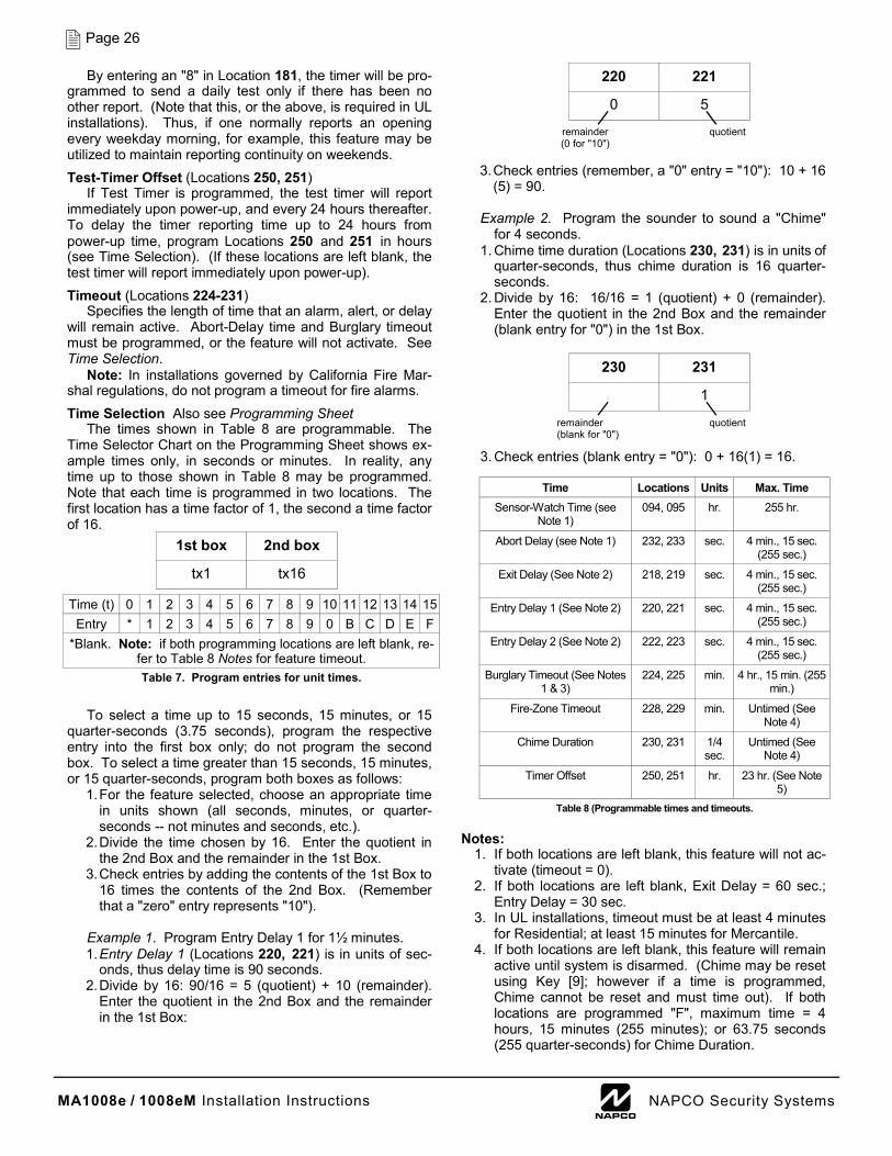
MA1008e / 1008eM Installation Instructions L NAPCO Security Systems
Page 26
By entering an "8" in Location 181, the timer will be pro-grammed to send a daily test only if there has been no other report. (Note that this, or the above, is required in UL installations). Thus, if one normally reports an opening every weekday morning, for example, this feature may be utilized to maintain reporting continuity on weekends.
Test-Timer Offset (Locations 250, 251) If Test Timer is programmed, the test timer will report
immediately upon power-up, and every 24 hours thereafter. To delay the timer reporting time up to 24 hours from power-up time, program Locations 250 and 251 in hours (see Time Selection). (If these locations are left blank, the test timer will report immediately upon power-up).
Timeout (Locations 224-231) Specifies the length of time that an alarm, alert, or delay
will remain active. Abort-Delay time and Burglary timeout must be programmed, or the feature will not activate. See Time Selection.
Note: In installations governed by California Fire Mar-shal regulations, do not program a timeout for fire alarms.
Time Selection Also see Programming Sheet The times shown in Table 8 are programmable. The
Time Selector Chart on the Programming Sheet shows ex-ample times only, in seconds or minutes. In reality, any time up to those shown in Table 8 may be programmed. Note that each time is programmed in two locations. The first location has a time factor of 1, the second a time factor of 16.
To select a time up to 15 seconds, 15 minutes, or 15
quarter-seconds (3.75 seconds), program the respective entry into the first box only; do not program the second box. To select a time greater than 15 seconds, 15 minutes, or 15 quarter-seconds, program both boxes as follows:
1. For the feature selected, choose an appropriate time in units shown (all seconds, minutes, or quarter-seconds -- not minutes and seconds, etc.).
2. Divide the time chosen by 16. Enter the quotient in the 2nd Box and the remainder in the 1st Box.
3. Check entries by adding the contents of the 1st Box to 16 times the contents of the 2nd Box. (Remember that a "zero" entry represents "10").
Example 1. Program Entry Delay 1 for 1½ minutes. 1. Entry Delay 1 (Locations 220, 221) is in units of sec-
onds, thus delay time is 90 seconds. 2. Divide by 16: 90/16 = 5 (quotient) + 10 (remainder).
Enter the quotient in the 2nd Box and the remainder in the 1st Box:
3. Check entries (remember, a "0" entry = "10"): 10 + 16
(5) = 90. Example 2. Program the sounder to sound a "Chime"
for 4 seconds. 1. Chime time duration (Locations 230, 231) is in units of
quarter-seconds, thus chime duration is 16 quarter-seconds.
2. Divide by 16: 16/16 = 1 (quotient) + 0 (remainder). Enter the quotient in the 2nd Box and the remainder (blank entry for "0") in the 1st Box.
3. Check entries (blank entry = "0"): 0 + 16(1) = 16.
Notes:
1. If both locations are left blank, this feature will not ac-tivate (timeout = 0).
2. If both locations are left blank, Exit Delay = 60 sec.; Entry Delay = 30 sec.
3. In UL installations, timeout must be at least 4 minutes for Residential; at least 15 minutes for Mercantile.
4. If both locations are left blank, this feature will remain active until system is disarmed. (Chime may be reset using Key [9]; however if a time is programmed, Chime cannot be reset and must time out). If both locations are programmed "F", maximum time = 4 hours, 15 minutes (255 minutes); or 63.75 seconds (255 quarter-seconds) for Chime Duration.
1st box 2nd box
tx1 tx16
Time (t) 0 1 2 3 4 5 6 7 8 9 10 11 12 13 14 Entry * 1 2 3 4 5 6 7 8 9 0 B C D E
*Blank. Note: if both programming locations are left blank, re-fer to Table 8 Notes for feature timeout. Table 7. Program entries for unit times.
15 F
220 221
0 5
remainder (0 for "10")
quotient
230 231
1
remainder (blank for "0")
quotient
Time Locations Units Max. Time Sensor-Watch Time (see
Note 1) 094, 095 hr. 255 hr.
Abort Delay (see Note 1) 232, 233 sec. 4 min., 15 sec. (255 sec.)
Exit Delay (See Note 2) 218, 219 sec. 4 min., 15 sec. (255 sec.)
Entry Delay 1 (See Note 2) 220, 221 sec. 4 min., 15 sec. (255 sec.)
Entry Delay 2 (See Note 2) 222, 223 sec. 4 min., 15 sec. (255 sec.)
Burglary Timeout (See Notes 1 & 3)
224, 225 min. 4 hr., 15 min. (255 min.)
Fire-Zone Timeout 228, 229 min. Untimed (See Note 4)
Chime Duration 230, 231 1/4 sec.
Untimed (See Note 4)
Timer Offset 250, 251 hr. 23 hr. (See Note 5)
Table 8 (Programmable times and timeouts.
MA1008e / 1008eM Installation Instructions L NAPCO Security Systems
Page 27
5. If left blank and Test Timer is selected, will report imme-diately on power-up.
6. In installations governed by California Fire Marshal regu-lations, do not program a timeout for fire alarms.
TouchTone® Dialing (Location 178) TouchTone® with Rotary Backup (Location 178)
Select TouchTone Dialing only when the subscriber has TouchTone service. TouchTone dialing is faster than rotary dialing, but not always as reliable.
For the communicator to use TouchTone on all dial at-tempts, add a "1" to Location 178. To use TouchTone on the first attempt with subsequent rotary dial attempts, add a "2" to Location 178. TouchTone Dialing will override TouchTone with Rotary Backup if both are selected. Note that if Backup Reporting is also selected, the communicator will use rotary dial to reach Telephone 2.
Trouble An abnormal zone condition (a break in a normally closed
loop; a short on a normally-open loop; or either on an end-of-line-resistor supervised loop) while disarmed.
Trouble on a Burglary Zone will be indicated by a sounder beep upon arming (does not apply to selective- or group-bypassed zones). If auto-bypass has been removed from a Burglary Zone, that zone will go into alarm on arming. Note that if the zone is Exit/Entry, it will go into alarm after exit-delay and entry-delay times have elapsed.
Trouble (open circuit) on a Day Zone (normally closed) will be indicated by a flashing green STATUS LED and a beeping sounder; the digital readout will display the troubled zone(s). Keypad indications are reset by Key [9].
A Fire-Zone trouble is indicated by the red FIRE/TROUBLE LED and by the sounder. An open circuit or short to ground on Fire Power (Terminal 11) or Aux. Power (Terminal 5) will cause a flashing LED and a pulsing sounder after a 10-second delay. (A short across the EOL resistor will cause an alarm condition: steady LED and pulsing sounder). Reset Key [9] will silence the sounder; the LED will go out within 30 seconds if the cause of the trouble has been re-moved. Note: Fire trouble restores are sent only after all zones are restored.
Two-Digit Format See Data Format
Untimed Output (NTO Lug E15; Locations 096-099) Audio Verification on NTO Lug (Location 305) Failure to Communicate on NTO Lug (Location 078) Keypad Aux. Alarm on NTO Lug (Location 079)
Lug E15 is an untamed output, programmable for any zone (Group 1 or Group 2). When tripped, the NTO Lug will go low. This output may be used for strobes (do not exceed 300mA), or to trip an LW-900 Long-Range Wireless Interface. A relay (400Ω minimum) may be connected between E15 and Terminal 5 (+ AUX. POWER) if a diode is inserted in series (cathode to E15; anode to relay coil).
Select Audio Verification on NTO Lug for the MAV-15 Two-Way Voice or other listen-in device. The NTO lug will go low when a programmed zone is tripped but will return high when the central-station communication is complete.
If Failure to Communicate on NTO Lug is programmed ("2" in Location 078), Lug E15 will go low after 9 unsuccessful transmissions, and remain low until either a transmission or a Telco Test is successful.
If Keypad Aux. Alarm on NTO Lug is programmed, Lug E15 will go low when the keypad Auxiliary Panic is tripped, and will remain low until the panel is disarmed.
Also see Abort Delay; Remote Status LED on NTO Lug.
User Program Code (Locations 238-243) Allows an authority to access the User Program Mode to
program any User Code (see GETTING UP AND RUNNING - Programming User Codes. The default User Program Code is 1,2,3,4,5,6, however this code must be changed to preserve system security. Enter the 3-to 6-digit User Program Code starting in Location 238.
Note: The Dealer Program Code must not start with the same numbers as the User Program Code.
User 5 Arm Only (Location 078) User 5 Report as User 1 (Location 078) Users 6, 7 & 8 Report as Users 2, 3 & 4 (Location 079) User 5 Service Code (Location 079)
To restrict User Code 5 as an "arm-only" code (for single-digit easy arming), program a "4" in Location 078 (Do not pro-gram User 5 Service Code). Note that if a single-digit arm-only code is programmed, the hold-down function for that digit is disabled.
The Service Code, if programmed, provides reduced ac-cess to the control panel for those with limited authority. Op-eration is similar to that of a regular Arm/Disarm Code, except that the Service Code is disabled at times. When active, it may be used to arm or disarm as needed.
The Service Code is controlled by User 1. Whenever User 1's code is entered, the Service Code is deactivated. To activate, merely arm using the Service Code. (The Service Code can always be used to arm). To enable User Code 5 as a Service Code, program a "1" in Location 079. For the Ser-vice Code to report, it must report as User 1 ("8" in Location 078). For Users 6, 7 and 8 to report, they must report as Us-ers 2, 3 and 4 ("4" in Location 079).
Watch On with Group Bypass (Location 081) The Watch Mode activates all Day Zones simultaneously.
When a "1" is entered in Location 081, the Watch Mode will be enabled when Group Bypass is selected (by pressing Key [B] twice). Note that (a) Group Bypass need not be pro-grammed for any zone for this feature to operate; (b) if a zone is programmed as a Day Zone, it may not be programmed for Group Bypass; and (c) Chime On with Group Bypass should not be programmed.
Zone Restore See Restore Report Normally, Control-Panel Restore is programmed for a
zone to send a restore report to the central station when either the zone is repaired or the panel is disarmed. If the restore report is to be sent only when the zone is repaired, Zone Re-store should be selected (also program Control Panel Re-store). It is recommended that Auto Reset and Priority Zone or Priority Zone with Bypass also be selected for proper op-eration. See Restore Report.
24-Hour Protection (Locations 198, 199) A zone that provides protection at all times, whether or
not the system is armed. Neither the green STATUS nor the red ARMED/ALARM LED will indicate the condition of a zone programmed for 24-Hour Protection, however an alarm will be logged into Alarm History (see Alarm History).
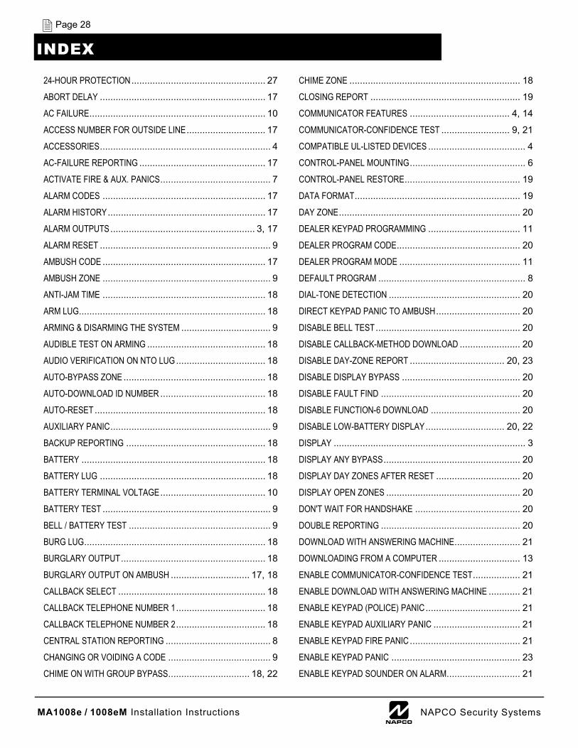
MA1008e / 1008eM Installation Instructions L NAPCO Security Systems
Page 28
24-HOUR PROTECTION ................................................... 27
ABORT DELAY ............................................................... 17
AC FAILURE ................................................................... 10
ACCESS NUMBER FOR OUTSIDE LINE .............................. 17
ACCESSORIES ................................................................. 4
AC-FAILURE REPORTING ................................................ 17
ACTIVATE FIRE & AUX. PANICS .......................................... 7
ALARM CODES .............................................................. 17
ALARM HISTORY ............................................................ 17
ALARM OUTPUTS ....................................................... 3, 17
ALARM RESET ................................................................. 9
AMBUSH CODE .............................................................. 17
AMBUSH ZONE ................................................................ 9
ANTI-JAM TIME .............................................................. 18
ARM LUG ....................................................................... 18
ARMING & DISARMING THE SYSTEM .................................. 9
AUDIBLE TEST ON ARMING ............................................. 18
AUDIO VERIFICATION ON NTO LUG .................................. 18
AUTO-BYPASS ZONE ...................................................... 18
AUTO-DOWNLOAD ID NUMBER ........................................ 18
AUTO-RESET ................................................................. 18
AUXILIARY PANIC ............................................................. 9
BACKUP REPORTING ..................................................... 18
BATTERY ...................................................................... 18
BATTERY LUG ............................................................... 18
BATTERY TERMINAL VOLTAGE ........................................ 10
BATTERY TEST ................................................................ 9
BELL / BATTERY TEST ...................................................... 9
BURG LUG ..................................................................... 18
BURGLARY OUTPUT ....................................................... 18
BURGLARY OUTPUT ON AMBUSH .............................. 17, 18
CALLBACK SELECT ........................................................ 18
CALLBACK TELEPHONE NUMBER 1 .................................. 18
CALLBACK TELEPHONE NUMBER 2 .................................. 18
CENTRAL STATION REPORTING ........................................ 8
CHANGING OR VOIDING A CODE ....................................... 9
CHIME ON WITH GROUP BYPASS ............................... 18, 22
CHIME ZONE ................................................................. 18
CLOSING REPORT ......................................................... 19
COMMUNICATOR FEATURES ...................................... 4, 14
COMMUNICATOR-CONFIDENCE TEST .......................... 9, 21
COMPATIBLE UL-LISTED DEVICES ..................................... 4
CONTROL-PANEL MOUNTING ............................................ 6
CONTROL-PANEL RESTORE ............................................ 19
DATA FORMAT ............................................................... 19
DAY ZONE ..................................................................... 20
DEALER KEYPAD PROGRAMMING ................................... 11
DEALER PROGRAM CODE ............................................... 20
DEALER PROGRAM MODE .............................................. 11
DEFAULT PROGRAM ........................................................ 8
DIAL-TONE DETECTION .................................................. 20
DIRECT KEYPAD PANIC TO AMBUSH ................................ 20
DISABLE BELL TEST ....................................................... 20
DISABLE CALLBACK-METHOD DOWNLOAD ....................... 20
DISABLE DAY-ZONE REPORT .................................... 20, 23
DISABLE DISPLAY BYPASS ............................................. 20
DISABLE FAULT FIND ..................................................... 20
DISABLE FUNCTION-6 DOWNLOAD .................................. 20
DISABLE LOW-BATTERY DISPLAY .............................. 20, 22
DISPLAY ......................................................................... 3
DISPLAY ANY BYPASS .................................................... 20
DISPLAY DAY ZONES AFTER RESET ................................ 20
DISPLAY OPEN ZONES ................................................... 20
DON'T WAIT FOR HANDSHAKE ........................................ 20
DOUBLE REPORTING ..................................................... 20
DOWNLOAD WITH ANSWERING MACHINE ......................... 21
DOWNLOADING FROM A COMPUTER ............................... 13
ENABLE COMMUNICATOR-CONFIDENCE TEST .................. 21
ENABLE DOWNLOAD WITH ANSWERING MACHINE ............ 21
ENABLE KEYPAD (POLICE) PANIC .................................... 21
ENABLE KEYPAD AUXILIARY PANIC ................................. 21
ENABLE KEYPAD FIRE PANIC .......................................... 21
ENABLE KEYPAD PANIC ................................................. 23
ENABLE KEYPAD SOUNDER ON ALARM ............................ 21
INDEX
MA1008e / 1008eM Installation Instructions L NAPCO Security Systems
Page 29
ENABLE KEYPAD TACTILE BEEP ...................................... 21
EXIT ENTRY FOLLOWER ................................................. 21
EXIT/ENTRY DELAY ........................................................ 21
EXTENDED FORMAT ....................................................... 21
FAILURE TO COMMUNICATE ........................................... 10
FAILURE TO COMMUNICATE ON NTO LUG ........................ 21
FAULT FIND ............................................................... 9, 21
FEATURES ...................................................................... 3
FIRE INSTALLATIONS ....................................................... 7
FIRE LUG ...................................................................... 21
FIRE PANIC ..................................................................... 9
FIRE ZONE .................................................................... 21
FORCE ARM REPORT ..................................................... 19
FORCE-ARM REPORT ..................................................... 22
GENERAL DESCRIPTION ................................................... 3
GROUNDING .................................................................... 6
GROUND-START MODULE ............................................... 22
GROUP BYPASS ............................................................. 22
HOLD-DOWN FUNCTIONS ................................................. 3
INCLUDE MANUAL BYPASS IN FORCE-ARM/STATUS .......... 22
INCLUDE MANUAL BYPASS IN FORCE-ARM/STATUS REPORT ................................................................................ 19
INSTALLATION ................................................................. 6
JUMPER OPTIONS ............................................................ 6
KEY INPUT ON ZONE 7 .................................................... 22
KEYPAD AUX. ALARM ON NTO LUG .................................. 22
KEYPAD AUXILIARY PANIC .............................................. 21
KEYPAD FIRE PANIC ....................................................... 21
KEYPAD FUNCTIONS ........................................................ 3
KEYPAD JUMPER OPTIONS ............................................... 6
KEYPAD MOUNTING ......................................................... 6
KEYPAD OPERATION ........................................................ 9
KEYPAD PANIC .......................................................... 9, 22
KEYPAD PROGRAMMING ................................................ 11
KEYPAD PROGRAMMING ................................................ 11
KEYPAD SOUNDER ON ALARM ........................................ 21
KEYPAD TACTILE BEEP .................................................. 21
KEYPAD WIRING .............................................................. 6
LINE-REVERSAL MODULE ............................................... 22
LISTEN-IN LUG ............................................................... 22
LOCAL DOWNLOADING ................................................... 13
LOOP RESPONSE .......................................................... 22
LOSS OF AC POWER ...................................................... 10
LOW BATTERY ......................................................... 10, 22
LUG E14 ........................................................................ 18
LUG E4 ......................................................................... 18
MERCANTILE BELL ........................................................... 7
MERCANTILE REQUIREMENTS .......................................... 5
MOUNTING ...................................................................... 6
NEVER ARM .................................................................. 22
NO AC .......................................................................... 22
NO END-OF-LINE RESISTOR ............................................ 22
NO OPENING REPORT AFTER ALARM ON ZONE 6 .............. 22
NTO LUG ....................................................................... 22
NUMBER OF RINGS .................................................. 18, 22
OPENING (CLOSING) CODES ........................................... 22
OPENING REPORT ......................................................... 22
OPENING REPORT AFTER ALARM .................................... 22
OPTIONAL PERIPHERALS ................................................. 4
ORDERING INFORMATION ................................................ 4
PANIC ZONE .................................................................. 23
PANICS ........................................................................... 7
PIR ZONE ...................................................................... 23
POLICE PANIC ................................................................. 9
POWER UP IN LAST STATE ............................................. 23
POWER-UP DELAY ......................................................... 23
POWER-UP SEQUENCE .................................................... 8
PRE-DIAL DELAY ............................................................ 23
PRIORITY ZONE ............................................................. 23
PRIORITY ZONE WITH BYPASS ........................................ 23
PROGRAM A USER CODE ................................................. 8
PROGRAM OPENING REPORT AFTER ALARM ................... 23
PROGRAMMING OVERVIEW ........................................ 3, 11
PROGRAMMING RECORD SHEETS ....................... 14, 15, 16
PROGRAMMING SHEETS ................................................ 12
PROGRAMMING STEPS .................................................. 12
PROGRAMMING USER CODES .......................................... 8
PROM PROGRAMMING ................................................... 13
MA1008e / 1008eM Installation Instructions L NAPCO Security Systems
Page 30
PULSING FIRE OUTPUT ................................................... 23
RECEIVER ..................................................................... 24
RECEIVER FORMAT ........................................................ 23
REMOTE DOWNLOADING ................................................ 13
REMOTE PANIC ............................................................... 6
REMOTE STATUS LED ON NTO LUG ................................. 24
REMOVE AUTO-BYPASS ................................................. 24
REPORT ON ALARM ....................................................... 24
REPORTING FEATURES .................................................... 4
RESET FIRE ................................................................... 24
RESET SHOCK SENSORS ON ARMING .............................. 24
RESET TEST TIMER ON REPORT ..................................... 24
RESTORE REPORT ......................................................... 24
SELECT USER(S) CLOSING ............................................. 24
SELECT USER(S) OPENING ............................................. 25
SELECTIVE BYPASS ....................................................... 25
SENSOR WATCH ...................................................... 23, 25
SERVICE CODE .......................................................... 9, 25
SINGLE-DIGIT FORMAT ................................................... 25
SMOKE DETECTORS .............................................. 4, 5, 25
SOUNDER OUTPUT ON LUG E4 ........................................ 25
SOUNDER SIGNALS .......................................................... 4
SPECIFICATIONS ............................................................. 4
SPLIT REPORTING ......................................................... 25
STATUS REPORT ..................................................... 19, 25
SUBSCRIBER IDENTIFICATION NUMBERS ......................... 25
SUM CHECK .................................................................. 25
SUM-CHECK FORMAT ..................................................... 19
SUMMARY OF UL REQUIREMENTS ..................................... 5
SWINGER SHUTDOWN .................................................... 25
SYSTEM FEATURES & TIMEOUTS .................................... 16
SYSTEM TROUBLE INDICATIONS ....................................... 9
TAMPER SWITCHES ......................................................... 6
TELEPHONE NUMBERS ................................................... 25
TEST TIMER .................................................................. 25
TESTING THE SYSTEM ................................................... 10
TEST-TIMER OFFSET ...................................................... 26
TIME SELECTION ........................................................... 26
TIMEOUT ....................................................................... 26
TIMES & TIMEOUTS ........................................................ 16
TOUCHTONE DIALING .................................................... 27
TRANSFERRING MEMORY FROM PROM ........................... 13
TRANSMITTERS ............................................................. 27
TROUBLE ...................................................................... 27
TWO-DIGIT EVENT CODE FORMAT ................................... 19
TWO-DIGIT FORMAT ....................................................... 27
UL/CUL LISTINGS ............................................................. 4
UNTIMED OUTPUT ......................................................... 27
USER 5 ARM ONLY ......................................................... 27
USER CODES .................................................................. 8
USER KEYPAD PROGRAMMING ......................................... 8
USER PROGRAM CODE .................................................. 27
USER PROGRAM MODE .................................................. 11
WATCH ON WITH GROUP BYPASS ................................... 27
ZONE FEATURES & KEYPAD CODES ................................ 15
ZONE RESTORE ............................................................ 27
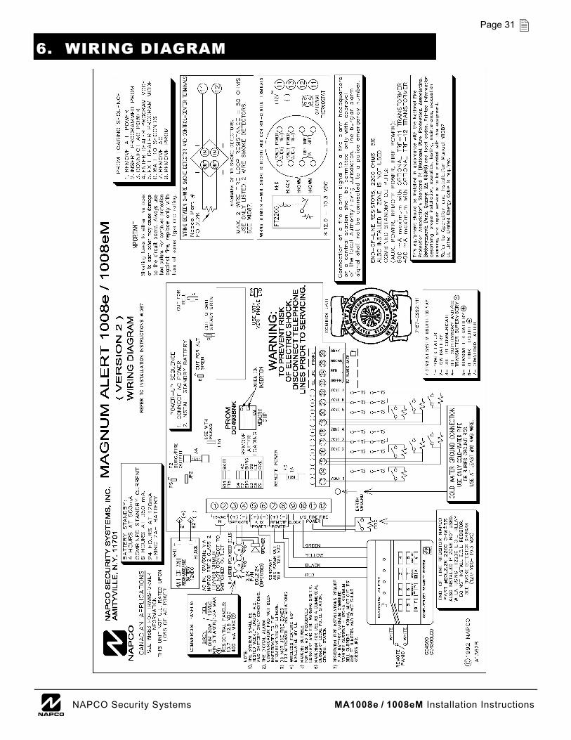
MA1008e / 1008eM Installation Instructions L NAPCO Security Systems
Page 31
6. WIRING DIAGRAM
MA1008e / 1008eM Installation Instructions L NAPCO Security Systems
Page 32
NAPCO SECURITY SYSTEMS, INC. (NAPCO) warrants its products to be free from manufacturing defects in materials and workmanship for thirty-six months following the date of manufacture. NAPCO will, within said period, at its option, repair or replace any product failing to operate correctly without charge to the original purchaser or user.
This warranty shall not apply to any equipment, or any part thereof, which has been repaired by others, improperly installed, improperly used, abused, altered, damaged, subjected to acts of God, or on which any serial numbers have been altered, defaced or removed. Seller will not be responsible for any dismantling or reinstallation charges.
THERE ARE NO WARRANTIES, EXPRESS OR IMPLIED, WHICH EXTEND BEYOND THE DESCRIPTION ON THE FACE HEREOF. THERE IS NO EXPRESS OR IMPLIED WARRANTY OF MERCHANTABILITY OR A WARRANTY OF FITNESS FOR A PARTICULAR PURPOSE. ADDITIONALLY, THIS WARRANTY IS IN LIEU OF ALL OTHER OBLIGATIONS OR LIABILITIES ON THE PART OF NAPCO.
Any action for breach of warranty, including but not limited to any implied warranty of merchantability, must be brought within the six months following the end of the warranty period.
IN NO CASE SHALL NAPCO BE LIABLE TO ANYONE FOR ANY CONSEQUENTIAL OR INCIDENTAL DAMAGES FOR BREACH OF THIS OR ANY OTHER WARRANTY, EXPRESS OR IMPLIED, EVEN IF THE LOSS OR DAMAGE IS CAUSED BY THE SELLER'S OWN NEGLIGENCE OR FAULT.
In case of defect, contact the security professional who installed and maintains your security system. In order to exercise the warranty, the product must be returned by the security professional, shipping costs prepaid and insured to NAPCO. After repair or replacement, NAPCO assumes the cost of returning products under warranty. NAPCO shall have no obligation under this warranty, or otherwise, if the product has been repaired by others, improperly installed, improperly used, abused, altered, damaged, subjected to accident, nuisance, flood, fire or acts of God, or on which any serial numbers have been altered, defaced or removed. NAPCO will not be responsible for any dismantling, reassembly or reinstallation charges.
This warranty contains the entire warranty. It is the sole warranty and any prior agreements or representations, whether oral or written, are either merged herein or are expressly cancelled. NAPCO neither assumes, nor
authorizes any other person purporting to act on its behalf to modify, to change, or to assume for it, any other warranty or liability concerning its products.
In no event shall NAPCO be liable for an amount in excess of NAPCO's original selling price of the product, for any loss or damage, whether direct, indirect, incidental, consequential, or otherwise arising out of any failure of the product. Seller's warranty, as hereinabove set forth, shall not be enlarged, diminished or affected by and no obligation or liability shall arise or grow out of Seller's rendering of technical advice or service in connection with Buyer's order of the goods furnished hereunder.
NAPCO RECOMMENDS THAT THE ENTIRE SYSTEM BE COMPLETELY TESTED WEEKLY.
Warning: Despite frequent testing, and due to, but not limited to, any or all of the following; criminal tampering, electrical or communications disruption, it is possible for the system to fail to perform as expected. NAPCO does not represent that the product/system may not be compromised or circumvented; or that the product or system will prevent any personal injury or property loss by burglary, robbery, fire or otherwise; nor that the product or system will in all cases provide adequate warning or protection. A properly installed and maintained alarm may only reduce risk of burglary, robbery, fire or otherwise but it is not insurance or a guarantee that these events will not occur. CONSEQUENTLY, SELLER SHALL HAVE NO LIABILITY FOR ANY PERSONAL INJURY, PROPERTY DAMAGE, OR OTHER LOSS BASED ON A CLAIM THE PRODUCT FAILED TO GIVE WARNING. Therefore, the installer should in turn advise the consumer to take any and all precautions for his or her safety including, but not limited to, fleeing the premises and calling police or fire department, in order to mitigate the possibilities of harm and/or damage.
NAPCO is not an insurer of either the property or safety of the user's family or employees, and limits its liability for any loss or damage including incidental or consequential damages to NAPCO's original selling price of the product regardless of the cause of such loss or damage.
Some states do not allow limitations on how long an implied warranty lasts or do not allow the exclusion or limitation of incidental or consequential damages, or differentiate in their treatment of limitations of liability for ordinary or gross negligence, so the above limitations or exclusions may not apply to you. This Warranty gives you specific legal rights and you may also have other rights which vary from state to state.
NAPCO LIMITED WARRANTY