m68000 family resident structured assembler … structured assembler reference manual ... m68000...
TRANSCRIPT

@M TOROLA M68KMASM/D8
M68000 Family Resident Structured Assembler
Reference Manual
QUALITY PEOPLE • PERFORMANCE

M68000 FAMILY
RESIDENT STRUCTURED ASSEMBLER
REFERENCE MANUAL
M68I<MASM/D8
JULY 1984
The information in this document has been carefully checked and is believed to be entirely reliable. However, no responsibility is assumed for inaccuracies. Furthermore, Motorola reserves the right to make changes to any products herein to improve reliability, function, or design. Motorola does not assume any liability arising out of the application or use of any product or circuit described herein; neither does it convey any license under its patent rights or the rights of others.
EXORmacs, SYMbug, SYSTEM V/68, VERSAdos, VERS.Amodule, VMC 68/2, VMEnodule, and VME/10 are trademarks of Motorola Inc.
This edition incorporates the information in any addendums to previous releases of this manual.
Eighth Edition
Copyright 1984 by Motorola Inc.
Seventh Edition July 1983


CHAPTER 1
1.1 1.2 1.3 1.3.1 1.3.2 1.4 1.4.1 1.4.2 1.4.3 1.5 1.6 1.7 1.8
CHAPTER 2
2.1 2.2 2.3 2.4 2.4.1 2.4.2 2.4.3 2.4.4 2.5 2.5.1 2.5.2 2.5.2.1 2.5.2.2 2.5.2.3 2.5.2.4 2.5.2.5 2.5.2.6
2.5.2.7
2.5.2.8
2.5.3 2.5.3.1 2.5.3.2 2.5.3.3 2.5.3.4 2.5.3.5
2.5.3.6
2.5.3.7
2.5.3.8 2.6 2.6.1
TABLE OF CONTENTS
GENERAL INFORMATION
SCOPE •••••••••••••••••••••••••••••••••••••••••••••••••••• INTRODOCTION ••••••••••••••••••••••••••••••••••••.••••••••• M68000 FAMILY ASSEMBLY LANGUAGE ..........................
Machine-instruction Operation Codes •••••••••••••••••••• Directives •••••••••••••••••••••••••••••••••••••••••••••
M68000 FAMILY RESIDENT STRUCTURED ASS:ENBLER •••••••••••••• Assembler Purposes ••••••••••••••••••••••••••••••••••••• Assembler Processing ••••••••••••••••••••••••••••••••••• Microprocessor Types •••••••••••••••••••••••••••••••••••
RELCX:::ATION AND LINKAGE••••••••••••••••••••••••••••••••••• LINKER RESTRICTIONS •••••••••••••••••••••••••••••••••••••• NOTATION ••••••••••••••••••••••••••••••••••••••••••••••••• RELATED PUBLICATIONS •••••••••••••••••••••••••••••••••••••
SOURCE PROGRAM CODING
INTRODUCTION••••••••••••••••••••••••••••••••••••••••••••• C0~1r1ENT S • • • • • • • • • • • • • • • • • • • • • • • • • • • • • • • • • • • • • • • • • • • • • • • • • EXECurABLE INSTRUCTION FORMAT•••••••••••••••••••••••••••• SOURCE LINE FORMAT •••••••••••••••••••••••••••••••••••••••
Label Field •••••••••••••••••••••••••••••••••••••••••••• Operation Field ···········~·••••••••••••••••••••••••••• O.[)erarrl Fi_eld •••••••••••••••••••••••••••••••••••••••••• Corrunent Field ••••••••••••••••••••••••••••••••••••••••••
ADDRESSING MODES ••••••••••••••••••••••••••••••••••••••••• Register Direct Modes •••••••••••••••••••••••••••••••••• Memory Address •••••••••••••••••••••••••••••••••••••••••
Address Register Indirect •••••••••••••••••••••••••••• Address Register Indirect with Postincrement ••••••••• Address Register Indirect with Predecrement •••••••••• Address Register Indirect with Displacement •••••••••• Address Register Indirect with Irrlex ••••••••••••••••• Address Register Indirect with Preindexing Plus
Base and Outer Displacement (MC68020 only) ••••••••• Address Register Indirect with Postindexing Plus
Base and Outer Displacements (MC68020 only) •••••••• Address Register Direct with Indexing Plus Base
Displacement (MC68020 only) •••••••••••••••••••••••• Special Address Modes ••••••••••••••••••••••••••••••••••
Absolute Short Address ••••••••••••••••••••••••••••••• Absolute Long Address •••••••••••••••••••••••••••••••• Program Counter with Displacement •••••••••••••••••••• Program Counter with Index ••••••••••••••••••••••••••• Program Counter with Preindexing Plus Base and
Outer Displacements •••••••••••••••••••••••••••••••• Program Counter with Postindexing Plus Base and
Outer Displacements (MC68020 only) ••••••••••••••••• Program Counter Direct with Indexing Plus Base
Displacement (MC68020 only) •••••••••••••••••••••••• Irnrnooiate I:>ata •••••••••••••••••••••••••••••••••••••••
NOTES ON MC68020 ADDRESSING MODES •••••••••••••••••••••••• .Address Register .Addressing Modes ••••••••••••••••••••••
i
1-1 1-1 1-2 1-2 1-2 1-2 1-3 1-3 1-3 1-3 1-4 1-4 1-5
2-1 2-1 2-1 2-2 2-2 2-2 2-4 2-4 2-4 2-9 2-9 2-9 2-9 2-10 2-10 2-10
2-11
2-12
2-13 2-14 2-14 2-14 2-15 2-15
2-16
2-17
2-18 2-18 2-19 2-19
2.6.2 2.6.3
TABLE OF CONTENTS (cont'd)
Program Counter Relative Addressing Modes ••••••••••••• Using Suppressed Registers to Force Redundant
2.6.4 2.7 2.8 2.8.l 2.8.2 2.8.3 2.8.4 2.8.5
Addressing Modes •••••••••••••••••••••••••••••••••••• Addressing Surrmary ••••••••••••••••••••••••••••••••••••
NOTES ON ADDRESSING OPTIONS ••••••••••••••••••••••••••••• SYMBOLS AND EXPRESSIONS •••••••••••••••••••••••••••••••••
Symbols ....•••..•••....•...•...•.•...•..•...•.• · • · · . · · Symbol Definition Classes ••••••••••••••••••••••••••••• User-Defined Labels ••••••••••••••••••••••••••••••••••• Integer Expressions ••••••••••••••••••••••••••••••••••• Q?erator Precedence •••••••••••••••••••••••••••••••••••
2.9 REGISTERS ••••••••••••••••••••••••••••••••••••••••••••••• 2.10 2.10.1 2.10.2 2.10.3 2.10.4 2.10.5 2.10.6 2.10.7 2.10.8 2.10.9 2.10.10 2.10.11 2.10.12 2.10.13 2.10.14 2.10.15 2.10.15.1 2.10.15.2 2.10.16 2.10.16.1 2.10.16.2 2.10.17 2.10.17.1 2.10.17.2 2.10.18 2.10.18.l 2.10.18.2 2.10.19 2.10.19.1 2.10.19.2 2.10.20 2.10.20.1 2.10.20.2 2.10.21 2.10.22 2.10.23 2.10.24 2.10.24.1 2.10.24.2 2.10.24.3 2.10.24.4 2.10.24.5
INSTRUCTION MNEMONICS••••••••••••••••••••••••••••••••••• Arithmetic Operations ••••••••••••••••••••••••••••••••• MOvE Instruction •••••••••••••••••••••••••••••••••••••• Compare and Check Instructions •••••••••••••••••••••••• Logical Operations •••••••••••••••••••••••••••••••••••• Shift Operations •••••••••••••••••••••••••••••••••••••• Bit Operations •••••••••••••••••••••••••••••••••••••••• Conditional O:perations •••••••••••••••••••••••••••••••• Branch Operations ••••••••••••••••••••••••••••••••••••• Jump Operations ••••••••••••••••••••••••••••••••••••••• DBcc Instruction •••••••••••••••••••••••••••••••••••••• Load/Store Multiple Registers ••••••••••••••••••••••••• Load Effective Address •••••••••••••••••••••••••••••••• Move to/from Control Register ••••••••••••••••••••••••• Move to/from Address Space •••••••••••••••••••••••••••• Bit Fields and Instructions (MC68020 only) ••••••••••••
Single Operand Bit Field Instruction •••••••••••••••• Double Operand Bit Field Instruction ••••••••••••••••
Check Instructions (MC68020 only) ················~···· Check Register Against Boards ••••••••••••••••••••••• Compare Register Against Boards •••••••••••••••••••••
Truncated Divide Instructions (MC68020 only) •••••••••• Truncated Signed Divide ••••••••••••••••••••••••••••• Truncated Unsigned Divide •••••••••••••••••••••••••••
Sign Extend Instructions (MC68020 only) ••••••••••••••• Sign Extend Byte •••••••••••••••••••••••••••••••••••• Sign Extend Word ••••••••••••••••••••••••••••••••••••
BCD Instructions (MC68020 only) ••••••••••••••••••••••• Pack BCD ••••••••••••••••••••••••••••••••••••••••••••
Unpack BCD•••••••••••••••••••••••••••••••••••••••••• Module Instructions (MC68020 only) ....................
Call Module ••••••••••••••••••••••••••••••••••••••••• Return from Module ••••••••••••••••••••.••••••••••••••
Trap on Condition Code (MC68020 only) ••••••••••••••••• Compare and Swap with Operand (MC68020 only) •••••••••• Breakpoint (MC68020 only) ••••••••••••••••••••••••••••• The MC68881 Co-Processor Instruction (MC68881 only) •••
Co-Processor Branch Conditionally ••••••••••••••••••• Decrement and Branch on Condition ••••••••••••••••••• Set on Condition •••••••••••••••••••••••••••••••••••• Trap on Condition, with or without a Parameter •••••• Co-Processor Save Function ••••••••••••••••••••••••••
ii
2-20
2-20 2-21 2-22 2-28 2-28 2-29 2-30 2-30 2-32 2-33 2-35 2-35 2-36 2-37 2-37 2-38 2-38 2-39 2-40 2-4i 2-41 2-42 2-43
·2-43 2-44 2-44 2-45 2-47 2-49 2-49 2-49 2-50 2-50 2-50 2-51 2-51 2-51 2-52 2-52 2-52 2-53 2-53 2-53 2-53 2-54 2-54 2-56 2-56 2-56 2-56 2-57 2-57
2.10.24.6 2.10.24.7
2.10.24.8
TABLE OF CONTENTS (cont'd)
Restore Internal State of Co-Processor ••••••••••••• Move to Floating-Point Register from Memory or fran
Another Floating-Point Register Instruction •••••• Move from Floating-Point Register to
2.10.26.9 2.10.26.10 2.10.26.11 2.10.26.12
Memory Instructions •••••••••••••••••••••••••••••• Floating-Point Functions ••••••••••••••••••••••••••• Floating-Point Arithmetic Operations ••••••••••••••• Floating-Point NO-OP ••••••••••••••••••••••••••••••• Floating-Point Test of an Operarrl ••••••••••••••••••
2.11
CHAPTER 3
3.1 3.2 3.2.1 3.2.2 3.2.3 3.2.4 3.2.5 3.2.6 3.3 3.3.1 3.3.2
3.3.3 3.3.4 3.4 3.4.1 3.4.2 3.4.2.1 3.4.2.2 3.4.3 3.4.4 3.5 3.5.1 3.5.2
3.5.3 3.5.4 3.5.5 3.5.6 3.5.7 3.5.8 3.5.9 3.5.10 3.5.11 3.5.12 3.5.13 3.6 3.6.1 3.6.2 3.6.3
VARIANTS ON INSTRUCTION TYPES ••••••••••••••••••••••••••
ASSEMBLER DIREcrIVES
INTRODUCTION•••••••••••••••••••••••••••••••••••••••••••
ASSEMBLY CONTROL••••••••••••••••••••••••••••••••••••••• END - Program Errl •••••••••••••••••••••••••••••••••••• INCLUDE - Include Secorrlary File ••••••••••••••••••••• MASK2 - Assemble for MASK2 (MC68000 only) •••••••••••• OFFSET - ~fine Offsets •••••••••••••••••••••••••••••• ORG - Absolute Origin •••••••••••••••••••••••••••••••• SECTION - Relocatable Program Section ••••••••••••••••
SYMBOL DEFINITION•••••••••••••••••••••••••••••••••••••• EQU - Equate Symbol Value •••••••••••••••••••••••••••• FEQU - F.quate Floating-Point Symbol Value
(MC68881 only) ..................................... REX; - Define Register List ••••••••••••••••••••••••••• SET - Set Symbol Value •••••••••••••••••••••••••••••••
DATA DEFINITION/STORAGE ALL~ATION ••••••••••••••••••••• COMLINE - Comman:1 Line ••••••••••••••••••••••••••••••• DC - Define Constant •••••••••••••••••••••••••••••••••
Examples of ASCII Strings •••••••••••••••••••••••••• Examples of Numeric Constants ••••••••••••••••••••••
IX:B - Define Constant Block •••••••••••••••••••••••••• DS - Define Storage ••••••••••••••••••••••••••••••••••
LISTING CONTROL AND OUTPUT OPTIONS ••••••••••••••••••••• FAIL - Programmer Generated Error •••••••••••••••••••• FOPT - Floating-Point Assembler Options
MC68020/MC68881 only) •••••••••••••••••••••••••••••• FORMAT - Format '!he Source Listing ••••••••••••••••• NOFORMAT - Do Not Format the Source Listing •••••••• LIST The Assembly •••••••••••••••••••••••••••••••••• NOLIST - Do Not List The Assembly •••••••••••••••••• LLEN - Line Lergth ••••••••••••••••••••••••••••••••• NOOBJ - No Object •••••••••••••••••••••••••••••••••• OPT - Assembler Output Options ••••••••••••••••••••• PAGE - Top Of Page ••••••••••••••••••••••••••••••••• NOPAGE - Do Not Page Source Output ••••••••••••••••• SPC - Space Between Source Liness •••••••••••••••••• TTL - Title ••••••••••••••••••••••••••••••••••••••••
LINKAGE EDITOR CONTROL ••••••••••••••••••••••••••••••••• IDNT Relocatable Identification Record ••••••••••••• XDEF External Symbol Definition •••••••••••••••••••• XREF External Symbol Reference •••••••••••••••••••••
iii
2-57
2-58
2-59 2-60 2-61 2-62 2-63 2-63
3-1 3-2 3-2 3-3 3-3 3-3 3-4 3-4 3-4 3-5
3-5 3-5 3-5 3-6 3-6 3-6 3-7 3-7 3-8 3-8 3-9 3-9
3-9 3-10 3-10 3-10 3-10 3-11 3-11 3-11 3-13 3-13 3-13 3-13 3-14 3-14 3-14 3-14

CHAPTER 4
4.1 4.2 4.2.1 4.2.2 4.2.3 4.3 4.3.l 4.4 4.5
CHAPTER 5
5.1 5.2 5.2.1 5.2.2 5.2.3 5.2.4 5.2.5 5.2.6 5.2.7 5.2.8 5.3 5.3.1 5.3.2
CHAPTER 6
6.1 6.2 6.3 6.3.l 6.3.2 6.3.3 6.3.4 6.3.5
6.4 6.4.1 6.4.1.1 6.4.1.2 6.4.2 6.5 6.5.1 6.5.2 6.5.3 6.5.4 6.6
TABLE OF CONTENTS (cont'd)
INVOKING THE ASSEMBLER
INTRODUCTION ••••••••••••••••••••••••••••••••••••••••••••• VERSAdos ENVIRONMENT •••••••••••••••••••••••••••••••••••••
Canmand Line Format ••••••••••••••••••••••••••••••••••••• Symbol Table Size Option ••••••••••••••••••••••••••••••• Microprocessor Type Option •••••••••••••••••••••••••••••
SYSTEM V/68 ENVIRONMENT•••••••••••••••••••••••••••••••••• Comnand Line Format ••••••••••••••••••••••••••••••••••••
ASSEivlBLER OUTPUT ••••••••••••••••••••••••••••••••••••••••• ASSEMBLER RUNTIME ERRORS •••••••••••••••••••••••••••••••••
MACRO OPERATIONS AND CONDITIONAL ASSEivlBLY
INTRODUCTION••••••••••••••••••••••••••••••••••••••••••••• MACRO OPERATIONS •••••••••••••••••••••••••••••••••••••••••
Macro Definition ••••••••••••••••••••••••••••••••••••••• Macro Invocation ••••••••••••••••••••••••••••••••••••••• Macro Parameter Definition and Use ••••••••••••••••••••• Labels within Macros ••••••••••••••••••••••••••••••••••• 'Ihe MEXIT Directive •••••••••••••••••••••••••••••••••••• NARG Symbol •••••••••••••••••••••••••••••••••••••••••••• Implementation of Macro Definition ••••••••••••••••••••• Implanentation of Macro Expansion ••••••••••••••••••••••
CONDITIONAL ASSEMBLY ••••••••••••••••••••••••••••••••••••• Conditional Assembly Structure ••••••••••••••••••••••••• Example of Macro and Con:litional Assembly Usage ••••••••
STRUCTURED CONTROL STATEMENTS
INTRODUCTION••••••••••••••••••••••••••••••••••••••••••••• KE'YW'ORD SYMBOLS •••••••••••••••••••••••••••••••••••••••••• SYNTAX •••••••••••••••••••••••••••••••••••••••••••••••••••
IF Statement ••••••••••••••••••••••••••••••••••••••••••• FOR Statanent •••••••••••••••••••••••••••••••••••••••••• REPEAT Statement ••••••••••••••••••••••••••••••••••••••• WHILE Statanent ••••••••••••••••••i••••••••••••••••••••• (MC68020/MC68881 only) Floating-Point Structure1
Assembler Syntax ••••••••••••••••••••••••••••••••••••• SIMPLE AND COMPOUND EXPRESSIONS ••••••••••••••••••••••••••
Simple Expressions ••••••••••••••••••••••••••••••••••••• Corrlition Code Expressions ••••••••••••••••••••••••••• Operan:l Canparison Expressions •••••••••••••••••••••••
Compound Expressions ••••••••••••••••••••••••••••••••••• SOURCE LINE FORMATTING •••••••••••••••••••••••••••••••••••
Class 1 Symbol Usage ••••••••••••••••••••••••••••••••••• Limite1 Free-Formatting •••••••••••••••••••••••••••••••• Nesting of StructurErl Statements ••••••••••••••••••••••• Assembly Listing Format ••••••••••••••••••••••••••••••••
EFFECTS ON THE USER'S ENVIRONMENT••••••••••••••••••••••••
iv
4-1 4-1 4-1 4-2 4-3 4-3 4-3 4-4 4-4
5-1 5-1 5-2 5-2 5-2 5-3 5-4 5-4 5-5 5-6 5-7 5-7 5-8
6-1 6-1 6-1 6-3 6-3 6-4 6-4
6-5 6-6 6-6 6-6 6-7 6-8 6-9 6-9 6-9 6-10 6-10 6-10
·rABLE OF CONTENTS (cont Id)
CHAPTER 7 GENERATING POSITION INDEPENDENT CODE
7.1 FORCING POSITION INDEPENDENCE •••••••••••••••••••••••••••• 7-1 7.2 BASE-DISPLACEMENT ADDRESSING ••••••••••••••••••••••••••••• 7-1 7.3 BASE-DISPLACEMENT IN CONJUNCTION WITH FORCED POSITION
APPENDIX A APPENDIX B APPENDIX C APPENDIX D
APPENDIX E
TABLE 2-1. 2-2.
2-3. 2-4. 2-5. 2-6. 2-7. 2-8.
2-9. 2-10. 2-11. 3-1. 4-1. 6-1.
INDEPENDENCE ••••••••••••••••••••••••••••••••••••••••••• 7-2
INSTRUCTION SET SUMMARY •••••••••••••••••••••••••••••••••• A-1 CHARACTER SET •••••••••••••••••••••••••••••••••••••••••••• B-1 SAMPLE ASSEMBLER OUTPUT •••••••••••••••••••••••••••••••••• C-1 EXAMPLE OF LINKED ASSEMBLY-LANGUAGE PROGRAMS
UNDER VERS.Ados ••••••••••••••••••••••••••••••••••••••••• D-1 ASSEMBLY ERROR CODES ••••••••••••••••••••••••••••••••••••• E-1
LIST OF TABLES
Address Modes •••••••••••••••••••••••••••••••••••••••••••• Cross-Reference: Effective Addressing Mode, Given Operand
Format and <expr> Type ••••••••••••••••••••••••••••••••• Special Address Ranges ••••••••••••••••••••••••••••••••••• Addressing Surru:nary ••••••••••••••••••••••••••••••••••••••• Operand Resolution ••••••••••••••••••••••••••••••••••••••• Known Location of Operand & Instruction Follows SECTION •• Known Location of Operand & Instruction Follows ORG •••••• Unknown Location of Operand & Instruction Follows
SECTION or ORG ••••••••••••••••••••••••••••••••••••••••• External Reference & Instruction Follows SECTION ••••••••• External Reference & Instruction Follows ORG ••••••••••••• MC68881 Specific Floating-Point Condition Codes (fpcc) ••• M68000 Family Assembler Directives ••••••••••••••••••••••• Standard Listing Format •••••••••••••••••••••••••••••••••• Effective Addressing Modes for Compare Instructions ••••••
v/vi
2-6
2-8 2-14 2-21 2-23 2-24 2-25
2-25 2-26 2-27 2-56 3-1 4-5 6-7

CHAPTER 1
GENERAL INFORMATION
1.1 SCOPE
The intent of this publication is to provide sufficient information to develop M68000 family assembly language programs, which may be run on MC68000-, MC68010-, or tvt::68020-based systems. The information herein pertains to the elements of the assembler. Detailed information pertaining to the f'1C68000 family of microprocessors is provided in the M68000 16/32-bi t Microprocessor Programner's Reference Manual. It is assumed that the designer has a complete understanding of the microprocessor architecture before attempting software developnent.
Chapters 1 through 4 contain the basic features of the assembler needed by the beginning assembly language programmer. Chapter 4 also provides instructions to invoke the assembler. .Advanced topics, such as macro operations, conditional assembly, and structured syntax, are described in Chapters 5 through 8.
1.2 INTRODUCTION
The M68000 Family Resident Structured Assembler (referred to as the "assembler" throughout this manual) is used to translate M68000 family assembler source programs into MC68000/f'1C68010/MC68020 machine language. The assembler executes under VERSAdos on the EXORmacs Developnent System, the VERSAmodule 01, 02, or 03 Monoboard Microcomputer, the VM:: 68/2 Microcomputer System, the VME/10 Microcomputer System, VMElnodule Monoboard Microcomputer (MVMElOl or MVMEllO) , or under SYSTEM V/68 on the EXORmacs Developnent System or the VME/10 Microcomputer System.
The assembler includes the following features:
• Absolute/relocatable code generation
• Complex expressions
• Symbol table listing
• Macros
• Conditional assembly
• Structured syntax
• Cross-reference
• IEEE Standard floating-point data types (MC68881 only)
1-1

1.3 M68000 FAMILY ASSEMBLY LANGUAGE
The symbolic language used to code source programs for processing by the assembler is called assembly language. This language is composed of the following symbolic elements:
a. Symbolic names or labels, which represent instruction, directive, and register mnemonics, as well as user-defined memory labels and macros.
b. Numbers, which may be represented in binary, octal, decimal, standard floating-point (MC68881 only) , or Binary Coded Decimal notation.
IEEE (BCD)
c. Arithmetic and logical operators, which are employed in complex expressions.
d. Special-purpose characters, which are used to denote certain operand syntax rules, macro functions, source line fields, and numeric bases.
1.3.l Machine-Instruction Operation Codes
Appendix A st.nnmarizes that part of the assembly language that provides mnemonic machine-instruction operation codes for the MC68000, MC68010, MC68020, and MC68881 machine instructions.
1.3.2 Directives
The assembly language contains mnemonics for directives which specify auxiliary actions to be performed by the assembler. Directives are not always translated to machine language.
Assembler directives assist the programner in controlling the assembler output, in defining data and symbols, and in allocating storage.
1.4 M68000 FAMILY RESIDENT STRUCTURED .ASSEMBLER
The assembler translates source statements written in the assembly language into relocatable or absolute object code, assigns storage locations to instructions and data, and performs auxiliary assembler actions designated by the programner. Object modules produced by the assembler are compatible with the M68000 family Linkage Editor or the SYSTEM V/68 PAL Linkage Editor, both also referred to as the "linkage editor" or "linker".
The assembler includes macro and conditional assembly capabilities, and implements certain "structured" programning control constructs. The assembler generates object code which may then be linked into a memory image format.
1-2

1.4.l Assembler Purposes
The two basic purposes of the assembler are to:
• Provide the prograTu~er with the means to translate source statements into object code -- that is, to the format required by the linkage editor •
• Provide a printed listing containing the source language input, assembler object code, arrl additional information (such as error cooes, if any) useful to the prograrrmer.
1.4.2 Assembler Processing
Assembly is a two-pass process. During the first pass, the assembler develops a symbol table, associating user-defined labels with values and addresses. During the second pass, the translation from source language to machine language takes place, using the symbol table developed during pass 1. In pass 2, as each source line is processed in turn, the assembler generates appropriate object code and the assembly listing.
1.4.3 Microprocessor Types
The assembler in its default ;node provides assembly of instructions for the MC68000 processor. However, the assembly of MC68010, MC68020, and MC68881 instructions can be enabled either as a directive in the source text which precedes instruction mnemonics or from the command line (refer to paragraphs 3.5.2.10 arrl 4.2.1, respectively).
1.5 RELO:ATION AND LINKAGE
"Relocation" refers to the process of binding a program to a set of memory locations at a ti!ne other than during the assembly process. For exa~ple, if subroutine 11 ABC" is to be used by many different programs, it is desirable to allow the subroutine to reside in any area of memory. One way of repositioning the subroutine in memory is to change the "ORG" directive operand field at the beginning of the subroutine, arrl then to reasse"Tlble the routine. A disadvantage of this method is the expense of reassambling ABC. An alternative to multiple assenililies is to assemble ABC once. Prcrluced is an object mooule, which contains enough information, so that another program (the linkage editor) can easily assign a new set of memory locations to the module. This scheme offers these advantages: reassembly is not required; the object module is substantially smaller than the source program; relocation is faster than reassembly, and relocation can be hanqled by the linkage editor (rather than by editing the source program an.1 changing the ORG directive).
In addition to progr~n relocation, the linkage editor must also resolve interprograrn references. For exa~ple, the other programs that are to use subroutine ABC must contain a jump-to-subroutine instruction to ABC. However, since ABC is not assembled at the same time as the calling program, the assembler cannot put the address of the subroutine into the operand field of the subroutine call. The linkage editor, however, will know where the calling program resides and, therefore, can resolve the reference to the call to ABC. This process of resolving inter-program references is called "linking". An example of linking two object modules is shown in Appendix D.
1-3
Program sections provide the basis of the relocation and linking scheme. Each of these sections may also have a variable number of named common sections associated with it, with each common section having a unique name. These relocatable sections are passoo on to the linkage editor. From the different modules that are to be linked, the linkage Erlitor collects all sections with the same number. Each of the 16 relocatable sections may contain data and/or code; in addition, named canmon sections may be defined within any relocatable section.
Absolute sections are unnumberErl (and, therefore, unlimited in number); they are specified by the ORG directive.
1.6 LINKER RESTRicrIONS
Before developing relocatable assembly language modules, the user should become familiar with the capabilities arrl restrictions of the linkage process, as outlined in the M68000 Family Linkage F.ditor User's Manual or the SYSTEM V/68 PAL Linkage F.di tor User's Manual. It is important to keep in mirrl that the relocation features of the assembler are directly attributable to capabilities of the linkage editor, am that the linkage environment can be controlled through assembler directives. If the assembly language object program is to be linked with a Pascal object program, the user should be aware of Pascal's requirements before allocation.
The assembler will produce an object module canpatible with the linkage editor. XDEF arrl XREF must be used to define entry points into the various modules and external symbols appearing in the module.
1.7 NOTATION
Corrmarrls arrl other input/output (I/O) are presented in this manual in a modified Backus-Naur Form (BNF) syntax. Certain symbols in the syntax, where note], are used in the real I/O; however, others are meta-symbols whose usage is restricted to the syntactic structure. These meta-symbols and their meanings are as follows:
< > The angular brackets enclose a symbol, known as a syntactic variable, that is replaced in a comnand line by one of a class of symbols it represents. In some cases, where noted, angular brackets are required characters.
[ ]
[ ] ...
This symbol indicates that a choice is to be made. One of several symbols, separated by this symbol, should be selectErl.
Square brackets enclose a symbol that is optional. The enclosed symbol may occur zero or one time. In some cases, where note], square brackets are requirErl characters.
Square brackets followed by periods enclose a symbol that is optional/repetitive. The symbol may appear zero or more times.
Operator entries are to be followed by a carriage return.
1-4

1.8 RELATED PUBLICATIONS
The user should be familiar with the following Motorola publications, as appropriate to system type.
EXORnacs Developnent System Operations Manual (M68KMACS)
\1ME/10 Microcomputer System Overview Manual (M68KVSOM)
VMC 68/2 Series Microcomputer System Manual (MVM::SM)
VERSAdos to VME Hardware and Software Configuration User's Manual (MVMEVDOS)
VERSAdos to VMEinodules Hardware and Software Configuration Manual (MVMECNFGl)
M68000 16/32-Bit Microprocessor Programmer's Reference Manual (M68000UM)
M68000 Family Linkage Editor User's Manual (M68KLINK)
M68000 Family Resident Pascal User's Manual (M68KPASC)
VERSAdos Messages Reference Manual (M68KVMSG)
VERSAdos System Facilities Reference Manual (M68KVSF)
SYSTEM V/68 Error Message Manual (M68KUNMSG)
SYSTEM V/68 PAL Linkage Editor User's Manual (M68KUNLNK)
SYSTEM V/68 Pascal Compiler User's Manual (M68KUNPAS)
SYSTEM V/68 User's Manual (M68KUNUM)
1-5/1-6


CHAPTER 2
SOURCE PROGRAM CODING
2.1 INTRODOcrION
A source program is a sequence of source statements arranged in a logical way to perform a predetermined task. Each source statement occupies a line of printable text, where each line may be one of the following:
a. Conment b. Executable instruction c. Assembler directive a. Macro invocation
NOTE
The MC68020 assemblers running under VERSAdos or SYSTEM V/68 and the t-e68000/MC68010 assembler running under SYSTEM V/68 are case-insensitive to source input except as noted under the H~LUDE directive or for ASCII strings. All instruction examples in this manual are in uppercase letters, excluding explanations.
2.2 COMMENTS
Conments are strings, composed of any ASCII characters (refer to Appendix B), which are inserted into a program to identify or clarify the individual statements or program flow. Comments are included in the assembly listing but are ignored by the assembler.
A cOlllment may be insertErl in one of two ways:
a. At the beginning of a line, starting in column one, where an asterisk (*) is the first character in the line. The entire line is a comment, and an instruction or directive in this line will not be recognized.
b. Following the operation and operand fields of an assembler instruction or directive, where it is preceded by at least one space (refer to paragraph 2.4.4}.
Examples:
* THIS ENT IRE LI NE IS A COMMENT.
BRA LAB2 THIS COMMENT FOLLOWS AN INSTRUCTION.
2.3 EXOCUTABLE INSTRUCTION FORMAT
Asse..-rnbly language progra~s are translated by the assembler into object code that may contain executable instructions, data structures, and relocation infonnation. This translation process be<Jins with symbolic assembly language source code, which employs reserved mnemonics, special symbols, and user-defined labels. M68000 family assembly language is line-oriented.
2-1
2.4 SOURCE LINE FORMAT
Each source statement has an overall format that is some combination of the following four fields:
a. label b. operation c. operand a. comment
The statement lines in the source file must not be numbered. The assembler, however, prefixes each line in the listing file with a sequential number, up to four decimal digits.
The format of each line of source code is described in the following paragraphs.
2.4.1 Label Field
The label field is the first field in the source line. A label which begins in the first column of the line may be terminated by either a space or a colon. A label may be preceded by one or more spaces, provided it is then terminated by a colon. In either case, the colon is not a part of the label.
Labels are allowed on all instructions and assembler directives which define data structures. For such operations, the label is defined with a value equal to the location counter for the instruction or directive, including a designation for the program section in which the definition appears.
Labels are required on the assembler directives which define symbol values (SET, EQU, REX;). For these directives, the label is defined with a value (and for SET and EQU, a progra~ section designation) corresponding to the expression in the operand field.
Labels on MACRO definitions are saved as the mnemonic by which that macro is subsequently invoked. No memory address is associated with such labels. A label is also required on the IDNT directive. This label is passed on to the relocatable object module; it has no associated internal value.
No other directives allow labels.
Labels which are the only field in the source line, are defined equal to the current location counter value and program section.
2.4.2 Operation Field
The operation field follows the label field and is separated from it by at least one space. Entries in the field fall under one of the following catec:3ories:
a. Instruction mnemonics - which correspond to the M68000 fa~ily processor instruction set.
b. Directive mnemonics - pseudo-operation codes for controlling the assembly process.
c. Macro calls - invocations of previously-described macros.
2-2

The size of the data field affected by an instruction is determined by the data size code. Sane instructions and directives can operate on more than one data size. For these operations, the data size code must be specified or a default size is assl.Ulled. The size code need not be specified if only one data size is permitted by the operation. The data size code is specified by appending a period (.) to the operation field, followed by B, W, L, s, D, X, or P where:
B = Byte (8-bit data)
W =Word (16-bit data)
L = Longword (32-bit data)
S = Byte (8-bit offset for certain branch instructions)
S = Single precision binary real (IEEE Standard, 32-bit: 8-bit exponent, 23-bit mantissa, 1-bit sign) (~68881 only)
D = Double precision binary real (IEEE Standard, 64-bit: 11-bit exponent, 52-bit mantissa, 1-bit sign) (MC68881 only)
X = Extended precision binary real (96-bit: 15-bit exponent, 64-bit mantissa, 1-bit sign) (MC68881 only), (16-bits are reserved)
P = Packed Binary Coded Decimal (BCD) real string (96-bit: 3-decimal digit exponent and 17-decimal digit mantissa) (MC68881 only)
The data size code is not permitted, however, when the instruction or directive does not have a data size attribute.
Examples (legal):
LEA 2(AO),Al
ADD.B ADDR,DO
ADD Dl,D2
ADD.L A3,D3
Example (illegal):
SUBA.B #5,Al
Longword size is assumed ( .B, .w not allowed); this instruction loads effective address pointed to by AO, +2 into Al.
This instruction adds byte whose address is ADDR to low order byte in DO.
This instruction adds low order word of Dl to low order word of D2. (W is the default size code.)
This instruction adds entire 32-bit (longword) contents of A3 to D3.
Illegal size specification ( .B not allowed on SUBA). This instruction attempts to subtract the value 5 from the low order byte of Al; byte operations on address registers are not allowed.
2-3

2.4.3 Operarrl Field
If present, the operand field follows the operation field and is separated from the operation field by at least one space. When two or more operand subfields appear within a statement, they must be separated by a comma but may not contain embedded spaces; e.g., Dl, D2 is illegal. In an instruction like 'ADD Dl,02', the first subfield (Dl) is generally applied to the second subfield (D2) and the results placed in the second subfield. Thus, the contents of Dl are added to the contents of D2; the result is saved in register D2. In the instruction 'MOVE Dl,D2', the first subfield (Dl) is the sending field; the second subfield (D2) is the receiving field. In other words, for most two-operand instructions, the general format 'opcode source,destination' applies.
2.4.4 Comment Field
The last field of a source statement is an optional comment field. This field is ignored by the assembler except for being included in the listing. The ccxnment field is separated from the operand field (or the operation field, if there is no operand) by one or more spaces and may consist of any ASCII characters. This field is important in documenting the operation of a program.
2.5 ADDRESSING MODES
Effective address modes, combinErl with operation codes, define the particular function to be performed by a given instruction. Effective addresses and data organization are described in detail in Section 2, "Data Organization and Addressing Capabilities", of the M68000 16/32-Bi t Microprocessor Programmer's Reference Manual.
References to data addresses may be odd only if a byte is referenced. Data references involving words or longwords must be even. Likewise, instructions must begin on an even byte boundary.
Individual bi ts within a byte (operand for memory destinations) or longwords (operarrls for Data register destinations) may be addressed with the bit
manipulation instructions (paragraph 2.10.6). Bits for a byte are numbered 7 to O, with 7 being the most significant bit position and 0 the least significant. Bits for a word are numbered 15 to O, with 15 being the most significant bit and 0 the least significant. Bits for a longword are numbered from 31 to O, with 31 being the most significant bit position and 0 the least significant bit position.
The code generated in the listing file for some addresses may be the same as the code generated for different expressions whenever externally referenced symbols are involved. The object file contains the correctly resolved addresses.
Following are definitions of the symbols used in Tables 2-1 and 2-2 and throughout the remainder of this section:
An
ZAn
Dn
Ri
Address register number "n" (0-7).
(MC68020 only) Suppressed address register number "n" (0-7) whose value is taken to be zero. Can be used in place of An if suppression is desired.
Data register number "n" (0-7).
(MC68020 only) Index register number "i "; may be any address (An) or data (Dn) register with optional ".W'' or ".L" size designation (16 vs 32 bits). Scaling factor "scl" may also exist.
2-4
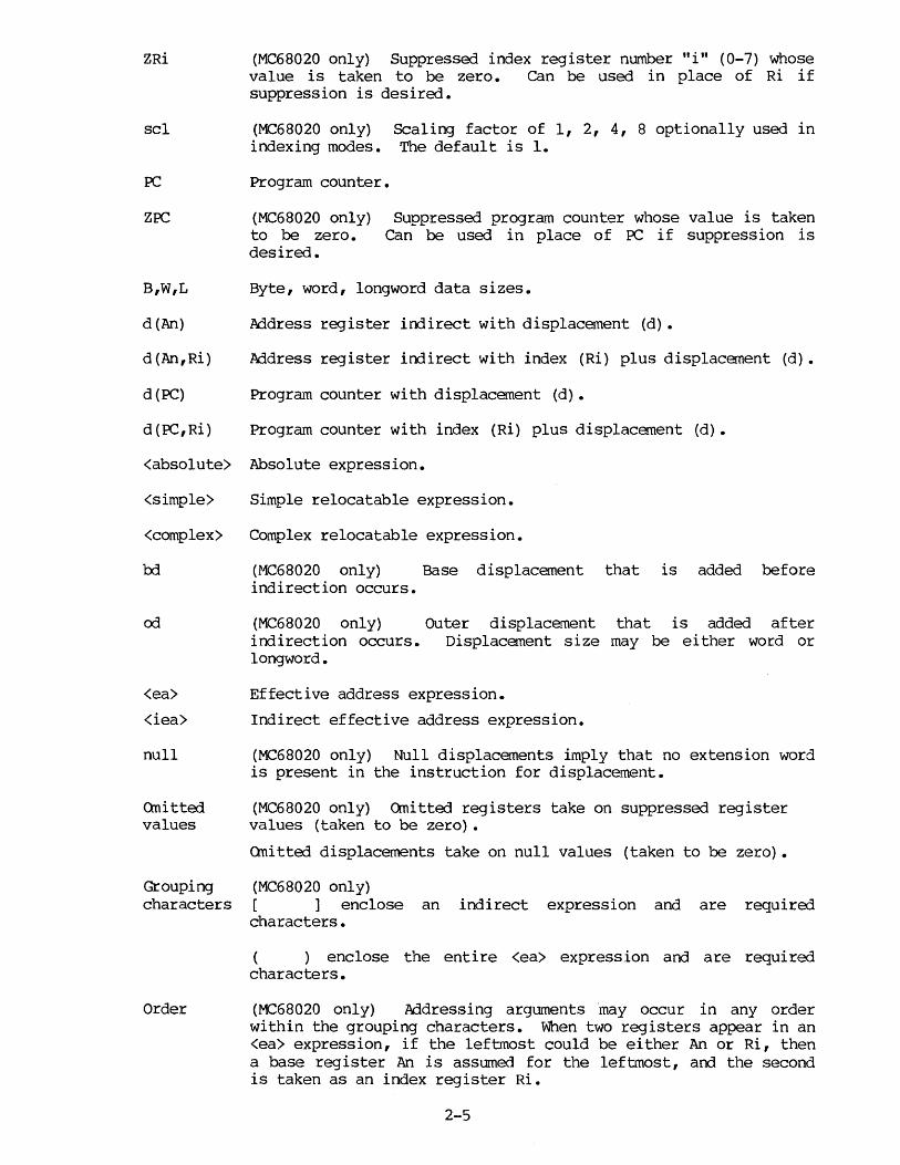
ZRi
scl
PC
ZPC
(MC68020 only) Suppressed index register number "i" (0-7) whose value is taken to be zero. can be used in place of Ri if suppression is desired.
(MC68020 only) indexing modes.
Scaling factor of 1, 2, 4, 8 optionally used in The default is 1.
Program counter.
(MC68020 only) to be zero. desired.
Suppressed program counter whose value is taken Can be used in place of PC if suppression is
B,W,L Byte, word, longword data sizes.
d(An) Address register indirect with displacement (d).
d(An,Ri) Address register indirect with index (Ri) plus displacement (d).
d(PC) Program counter with displacement (d).
d(PC,Ri) Program counter with index (Ri) plus displacement (d).
<absolute> Absolute expression.
<simple> Simple relocatable expression.
<complex> Complex relocatable expression.
bd
od
<ea>
<iea>
null
Quitted values
Grouping characters
Order
(MC68020 only) Base displacement that is added before indirection occurs.
(MC68020 only) Outer displacement that is added after indirection occurs. Displacement size may be either word or longword.
Effective address expression.
Indirect effective address expression.
(MC68020 only) Null displacements imply that no extension word is present in the instruction for displacement.
(MC68020 only) Qnitted registers take on suppressed register values (taken to be zero) •
Quitted displacements take on null values (taken to be zero).
(MC68020 only) [ ] enclose an indirect expression and are required characters.
( ) enclose the entire <ea> expression and are required characters.
(MC68020 only) Addressing arguments ·may occur in any order within the grouping characters. When two registers appear in an <ea> expression, if the leftmost could be either An or Ri, then a base register An is assumed for the leftmost, and the second is taken as an index register Ri.
2-5
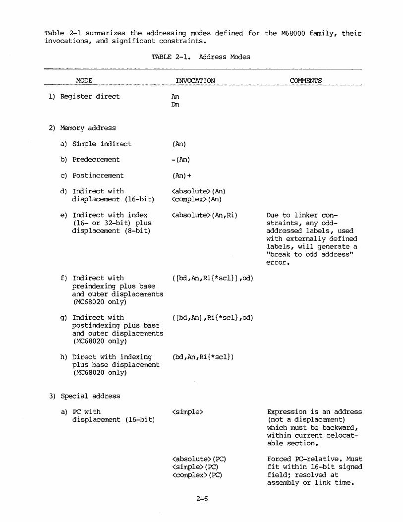
Table 2-1 summarizes the addressing modes defined for the M68000 family, their invocations, and significant constraints.
TABLE 2-1. Address Modes
MODE
1) Register direct
2) Memory address
a) Simple indirect
b) Predecrement
c) Post increment
d) Indirect with displacement (16-bit)
e) Indirect with index (16- or 32-bit) plus displacement (8-bit)
f) Indirect with preindexing plus base and outer displacements (MC68020 only)
g) Indirect with postindexing plus base and outer displacements (MC68020 only)
h) Direct with indexing plus base displacement (MC68020 only)
3) Special address
a) PC with displacement (16-bi t)
INVOCATION
An Dn
(An)
-(An)
(An)+
<absolute>(An) <complex>(An)
<absolute>(An,Ri)
([bd,An,Ri{*scl}] ,od)
( [bd,An] ,Ri{*scl} ,od)
(bd ,An,Ri {*scl})
<simple>
<absolute> (PC) <simple> (PC) <complex>(PC)
2-6
COMMENTS
Due to linker constraints, any oddaddressed labels, used with externally defined labels, will generate a "break to odd address" error.
Expression is an address (not a displacement) which must be backward, within current relocatable section.
Forced PC-relative. Must fit within 16-bit signed field; resolved at assembly or link time.

TABLE 2-1. Address Modes (cont'd)
MODE
b) PC with index (16- or 32-bit) plus displacement (8-bit)
c) PC with preindexing plus oose and outer displacements (MC68020 only)
d) PC with postindexing plus base arrl outer displacements (MC68020 only)
e) PC direct with indexing plus base (MC68020 only)
f) Absolute (16- or 32-bi t)
g) Imnediate (8-, 16-, or 32-bi t)
INVOCATION
<absolute>(PC) <simple> (PC) <complex>(OC)
<simple> (Ri)
<absolute>(PC,Ri) <simple> (PC, Ri)
([bd,OC,Ri{*scl}],od)
([bd,PC),Ri{*scl}] ,od)
(bd,PC, Ri {*scl})
<absolute> <complex> <simple>
#<absolute> #<simple> #<complex>
2-7
COMMENTS
Forced PC-relative. Must fit within 16-bit signed field; resolved at assembly or link time.
Expression is an address which must be backward, within current relocatable section. Also, due to linker constraints, any odd-addressed labels, used with externally defined labels, wi 11 generate a "break to odd address" error.
Forced PC-relative; expression must be within current program section.
Expression must be forward reference or not in current program section.
Due to linker constraints, any oddaddressed labels, used with externally defined labels, will generate a "break to odd address" error.

MODE
4) Implicit PC reference
TABLE 2-1. .Address Modes (cont'd)
INVOCATION COMMENTS
Invoked by conditional branch (Bee) or DBcc instruction; the effective address is a displaceuent fran the PC; the displacement is either 8, 16, or 32 bits (32 on ~68020 only), depending on OPT BRS, OPT BRB, OPT BJ:M, and OPT BRL, arrl whether these options are overridden on the current instruction (see paragraph 2.6). Also, due to linker constraints, any odd-addressed labels, used with externally defined labels, will generate a "break to odd address" error.
Table 2-2 provides a cross reference of operand formats and addressing modes. Given an op:rand of the format shown in the first column, the other columns show which addressing mode is indicated, depending on whether the expression is absolute, simple relocatable, or complex relocatable.
TABLE 2-2. Cross-Reference: Effective Addressing Mode, Given Operand Format and <expr> Type
EFFECTIVE ADDRESSING MODE
ABSOLUTE SIMPLE RELcx::ATABLE COMPLEX RELOCATABLE OPERAND FORMAT <expr> <expr> <expr>
<expr>(An) d(An) d (An) d (An)
<expr> (Dn) invalid d (PC,Dn) * invalid
<expr> (An,Ri) d(An,Ri) invalid invalid
<expr> absolute (W,L) d (PC) or absolute (W,L) absolute (W,L)
<expr> (PC) d (PC) d (PC) d (PC)
<expr> (PC, Ri) d (PC, Ri) * d (PC, Ri) * invalid
#<expr> immediate (B,W, L) immediate (W, L) immediate (W,L)
* Must be within current program section.
2-8
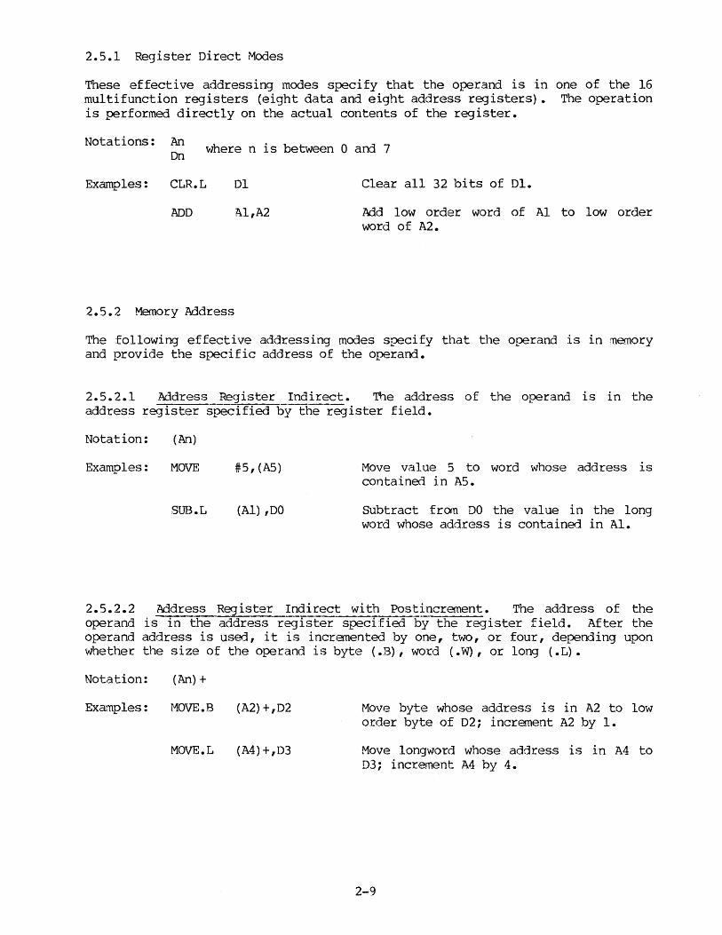
2.5.l Register Direct Modes
These effective addressing modes specify that the operand is in one of the 16 multifunction registers (eight data and eight address registers) • The operation is performed directly on the actual contents of the register.
Notations: An On where n is between 0 and 7
Examples: CLR.L
ADD
2.5.2 Memory Address
Dl
Al,A2
Clear all 32 bits of Dl.
Add low order word of Al to low order word of A2.
The following effective addressing modes specify that the operand is in memory and provide the specific address of the operand.
2.5.2.l Address Register Indirect. The address of the operand is in the address register specified by the register field.
Notation: (An)
Examples: MOVE
SUB.L
#5,(A5)
(Al) ,DO
Move value 5 to word whose address is contained in A5.
subtract from DO the value in the long word whose address is contained in Al.
2.5.2.2 Address Register Indirect with Postincrement. The address of the operand is in the address register speci:Eied by the register field. After the operand address is used, it is incremented by one, two, or four, depending upon whether the size of the operand is byte ( .B), word ( .W), or long ( .L).
Notation: (An)+
Examples: MOVE.B
MOVE.L
(A2)+,D2
(A4)+,D3
Move byte whose address is in A2 to low order byte of 02; increment A2 by 1.
Move longword whose address is in A4 to D3; increment A4 by 4.
2-9
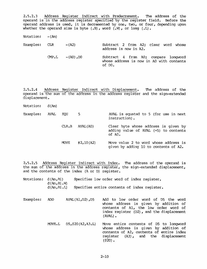
2.5.2.3 Address Register Indirect with Predecrement. The address of the operand is in the address register specified by the register field. Before the operand address is used, it is decremented by one, two, or four, depending upon whether the operand size is byte (.B), word (.W), or long (.L).
Notation: -(An)
Examples: CLR
CMP.L
-(A2)
-(AO) ,DO
Subtract 2 from A2; clear word whose address is now in A2.
Subtract 4 fran AO; compare longword whose address is now in AO with contents of DO.
2.5.2.4 Address Register Indirect with Displacement. The address of the operand is the sum of the address in the address register and the sign-extended displacement.
Notation: d(An)
Examples: AVAL EQU 5
CLR.B AVAL(AO)
MOVE #2,10(A2)
AVAL is equated to 5 (for use in next instruction) •
Clear byte whose address is given by adding value of AVAL (=5) to contents of AO.
Move value 2 to word whose address is given by adding 10 to contents of A2.
2.5.2.5 Address Register Indirect with Index. The address of the operand is the sum of the address in the address register, the sign-extended displacement, arrl the contents of the index (A or D) register.
Notations: d(An,Ri) Specifies low order word of index register.
Examples:
d (An,Ri.W) d(An,Ri.L) Specifies entire contents of index register.
ADD AVAL (Al,02) ,OS
MOVE.L D5,$20(A2,A3.L)
Add to low order word of 05 the word whose address is given by addition of contents of Al, the low order word of index register (D2) , and the displacement (AVAL) •
Move entire contents of D5 to longword whose address is given by addition of contents of A2, contents of entire index register (A3) , and the displacement ( $20) •
2-10

2.5.2.6 Address Register Indirect with Preindexing Plus Base and Outer Displacements. (MC68020 only) The address of the operand is the sum of the <iea> and a sign-extended outer displacement value od. <iea> is the sum of the contents of the address register An (or ZAn), the base displacanent bd, and the contents of the index register Ri (or ZRi) • Therefore,
Notation:
bd + (An) + Ri (<iea>) + od
---> <iea> ---> <operand>
([bd,An,Ri{*scl}] ,od) or ([bd,An,Ri.W{*scl}] ,od)
([bd,An,Ri.L{*scl}] ,od)
Specifies low-order word of index register Ri.
Specifies entire contents of index register Ri.
Examples: ADD ( [BASE,Al,D2] ,AVAL) ,DS The sum of the value of BASE, the contents of base register Al, and the contents of the low-order word of index register D2 points to <iea>. The contents of the resultant address <iea> added to the value of AVAL give the <ea> of the operand to be added to the contents of DS.
ADD ([2,Al,A2] ,4) ,DS
2-11
In this example, the assembler selects the leftmost A register (Al) to be the base register.

2.5.2.7 Address Register Indirect with Postindexing Plus Base and Outer Displacements. (MC68020 only) The address of the operand 1s the sum of the <iea>, the contents of the irrlex register Ri (or ZRi), arrl the outer displacement value od. <iea> is the sum of the base displacement bd and the contents of the base register An (or ZAn). Therefore,
Notation:
bd + (An) (<iea>) + od + Ri
---> --->
([bd,An] ,od,Ri{*scl}) or ([bd,An] ,od,Ri.W{*scl})
([bd,An] ,od,Ri.L{*scl})
<iea> <operand>
Specifies low-order word of index register Ri.
Specifies entire contents of index register Ri.
Example: ADD ([BASE,Al] ,AVAL,D2) ,DS The sum of the value of BASE and the contents of base register Al points to <iea>. The contents of the resultant address <iea> added to the value of AVAL and the low-order word of index register D2 points to the address of the operand to be added to the contents of D5.
2-12

2.5.2.8 Address Register Direct with Indexing Plus Base Displacement. (M:::::68020 only) The address of the operand is the sum of the 8-bit base displacement bd, the contents of the base register An, arrl the contents of the index register Ri. Therefore,
bd + (An) + (Ri) ---> <operand>
Notation: (bd,An,Ri{*scl}) or (bd,An,Ri.W{*scl})
(bd,An,Ri.L{*scl})
Example: ADD (BASE,Al,D2) ,D5
ADD (BASE,Al,A2) ,05
Specifies low-order word of irrlex register Ri.
Specifies entire contents of index register Ri.
The sum of the value of BASE, the contents of base register Al, and the low-order word of index register D2 points to the address of the operand to be added to the contents of D5.
In this example, Al is the base register because it is the leftmost candidate for base register. A2 is interpreted as being an index register.
2-13

2.5.3 Special Address Modes
Special address modes use the effective address register field to specify the special addressing m~1e instead of a register number. Table 2-3 provides the ranges for absolute short and long addresses.
TABLE 2-3. Special Address Ranges
32-BIT ADDRESS 16-BIT REPRESENTATION OF 32-BIT ADDRESS
00000000 0000
00007FFF
00008000
FFFF7FFF
FFFF8000
FFFFFFFF
Absolute short
7FFF
(No representation in 16 bits; must be absolute long)
8000
7llisolute short FFFF
2.5.3.1 Absolute Short Address. The 16-bit address of the operand is sign extended before it is used. Therefore, the useful address range is 0 through $7FFF and $FFFF8000 through $FFFFPFFF.
Notation: XXX
Example: ,JMp $400 Jump to hex address 400
(M268020 only) An absolute short address can be forced by using the notation:
(XXX) .W
2.5.3.2 Absolute Long Address - The address of the operand is the 32-bit value specified.
Notation: XXX
Example: JMP $12000 Jump to hex address 12000
(MC68020 only) An absolute long address can be forced by using the notation:
(XXX) .L
2-14

2.5.3.3 Program Counter with Displacement. The address of the operand is the sum of the address in the program counter and the sign-extended displacement integer. The assembler calculates this sign-extended displacement by subtracting the address of displacement word "from the value of the operand field.
Notation:
Example:
<expression>(~)
JMP TAG(PC)
Forced program counter-relative. Note that <expression> is interpreted as a program address rather than a displacement.
Force the jump to address TAG to be program counter-relative.
2.5.3.4 Program Counter with Index. The address is the sum of the addr·2ss in the program counter, the sign-extended displacement value, and the contents of the irrlex (A or D) register.
Notations: <expression>(Ri.rN)
<expression>(Ri.L)
<expression>(PC,Ri)
Examples: MOVE T(D2) ,TABLE
JMP TABLE ( A2. W)
,JMp TAG(P2,A2. W)
Specifies register.
low order word of index .W is optional (default).
Specifies entire contents of index register.
Forced program counter-relative. Ri .w or Ri. L legal. NOTE: <expression> is interpreted as a program address rather than a displacement.
Moves word at location (T plus contents of D2) to word location defined by TABLE. T must be a relocatable symbol.
Transfers control to location defined by TABLE plus the lower 16-bit content of A2 with sign extension. TABLE must be a relocatable symbol.
Forces evaluation of TAG to be program counter-relative with index.
2-15

2.5.3.5 Program Counter with Preindexing Plus Base and Outer Displacements. (MC68020 only) The address of the operand is the sum of the <iea> and a signexterrled outer displacement value od. <iea> is the sum of the contents of the Program Counter PC (or ZPC), the base displacement l:rl, and the contents of the irrlex register Ri (or ZRi) • Therefore
bd + (PC) + Ri ---> (<iea>) + od --->
<iea> <operand>
NOTE
Whenever ZPC is usErl, l:rl is not offset by the current PC value. od is never offset by the PC value.
Notation: ([bd,PC,Ri{*scl}] ,od) or ([bd,PC,Ri.W{*scl}],od)
( [bd,PC,Ri .L{*scl}] ,od)
Specifies low-order word of index register Ri.
Specifies entire contents of index register Ri.
Examples: ADD ([BASE,PC,A2] ,AVAL),05 The sum of the value of BASE, the contents of the program counter PC, and the contents of the low-order word of index register 2 points to <iea>. The contents of the resultant address <iea> added ,to the value of AVAL give the <ea> of the operand to be added to the contents of DS.
ADD ([A2,PC,BASE],AVAL),D5
2-16
This example is equivalent to the example above because ordering of operands is not required.

2.5.3.6 Program Counter with Postindexing Plus Base and Outer Displacements. (MC68020 only) The address of the operand is the sum of the <iea>, the contents of the irrlex register Ri (or ZRi), arrl the outer displacement value od. <iea> is the sum of the base displacement bd. and the contents of the program counter PC (or ZPC). Therefore,
Notation:
bd. + (PC) (<iea>) + od + Ri
---> <iea> ---> (operand>
Notes: Whenever ZPC is userl, bd. is not offset by the current PC value. od is never offset by the PC value.
([bd.,PC] ,od,Ri{*scl}) or ( [ bd, PC) 1 od, Ri • W { * sc l} )
([bd,PC],od,Ri.L{*scl})
Specifies low-order word of index register Ri.
Specifies entire contents of the index register Ri.
Example: ADD ([BASE,PC],AVAL,D2),D5 The sum of the value of BASE and the contents of program counter PC points to <iea>.
2-17
The contents of the resultant address <iea> added to the value of AVAL and the low-order word of index register D2 points to the address of the operand to be added to the contents of DS.

2.5.3.7 Program Counter Direct with Indexing Plus Base Displacanent. (MC68020 only) The address of the operand is the sum of the sign-extended 8-bi t base displacement bd, the contents of the program counter PC, and the contents of the index register Ri. Therefore,
bd + (PC) + (Ri) ---> <operand>
Notation: (bd,PC,Ri{*scl}) or (bd,PC,Ri.W{*scl})
(bd,PC,Ri.L{*scl})
Specifies low-order word of index register Ri.
Specifies entire contents of the index register Ri.
Example: ADD (BASE,PC,D2),D5 The sum of the value of BASE, the contents of program counter PC, arrl the contents of the low-order word of D2 points to the address of the operand to be added to the contents of DS.
2.5.3.8 Imme:Hate Data. An absolute number may be specified as an operand by irrrnediately preceding a number or expression with an immediate character. The immerliate character (#) is used to designate an absolute number other than a displacement or an absolute address.
Notation: #XXX
Examples: MOVE
SUB.L
#1,DO
#1,DO
Move value 1 to low order word of DO.
Subtract value 1 from the entire contents of DO.
2-18

2.6 NOTES ON MC68020 ADDRESSING MODES
There are new features in the MC68020 addressing modes. These features are discussed in the following paragraphs and are sumnarized in Table 2-4.
2.6.1 .Address Register .Addressing Modes
One of the main changes to the addressing modes in the MC68020 is in the mode 6 <ea> expressions. Some source code variations of the new mode 6 <ea> expressions are redundant with the MC68000 modes 2 and 5 (i.e., the final effective address is the same). When a redundant mode occurs, the mode 2 and 5 forms are selected by the assembler because they are more efficient. For example, when the assembler sees the following form:
(An)
it will generate a mode 2 addressing mode. Furthermore, the assembler will generate a mode 5 address when seeing the following two forms:
bd (An) (bd,An)
or the new syntax form when bd fits in 16 bits or less
The programmer can generate the redundant mode 6 instructions by using the suppressed registers. In the bd (An) form, bd must fit in 16 bits or less or an error (250) is generated. The (bd, An) form supports a bd up to 32 bits.
It is important to note that the assembler still recognizes the current 68000 syntax for mode 6 addresses. These two forms are:
(An, Ri) bd(An,Ri) or the new notation (bd,An,Ri)
They generate mode 6 addresses. However, the object code for the form written in new notation is different if a scaling factor other than one is present or bd cannot be represented in 8 bits or less.
Where new addressing modes are redundant with old addressing modes or with other new addressing modes, the assembler defaults to the more efficient addressing mode. However, less efficient forms can still be generated.
In general, old addressing modes are more efficient than the new modes. Within the new modes, pre-indexed indirect is more efficient than post-indexed indirect, and use of the index register is more efficient than use of the base address register for indirect modes.
Efficiency as used in this document refers to execution time. the fastest variation is also the shortest one.
In most cases,
In the variation (bd,Ai*scl), the form (bd,Ai) is accepted. However, if the base displacement is less than or equal to 16 bits, the assembler automatically selects mode 5.
2-19

2.6.2 Program Counter Relative l\Cldressing Modes
Another major change to the addressing modes in the MC68020 is in the mode 73 forms. Some of the new mode 73 addressing modes are redundant with the MC68000 mode 72. When a redundant mode occurs, the mode 72 form is used since it is more efficient. For example, when the assembler sees
bd (PC) or the new syntax form
(bd,PC) when bd fits in 16 bits or less
it generates a mode 72 address. The programmer can generate the redundant mode 73 instructions by using suppressed registers.
It is also important to note that the assembler recognizes the current 68000 syntax for mode 73 addresses. These forms are
(PC,Ri) or (PC) or bd(PC,Ri)
All mode 73 <ea> expressions require 'PC' or 'ZPC' as part of the expression to distinguish them from their address register counterparts. (All mode 72 and 73 references are to program space and all mode 2, 5, and 6 references are to data space.)
Where new addressing modes are re::Iundant with old addressing modes or with other new addressing modes, the asse.rubler defaults to the more efficient addressing mode. However, less efficient forms can still be generated.
TNhen the program counter is suppressed (ZPC) , the displacement is assu11ed to be absolute and hence is not offset from the current PC value.
2.6.3 Using Suppressed Registers to Force Redundant Addressing Modes
Register mnemonics ZPC, ZAO-ZA7 and ZDO-ZD7 imply registers whose values are always taken to be zero. These symbols may be used to specify any allowable register while at the same time suppressing that register during <ea> calculations. These symbols are included for diagnostic purposes so that every field of the object code instruction can be specified. It also indicates whether PC or An is being suppressed, an<l this determines whether the <ea> is in instruction space or data space. By default, An is taken to be the suppressed register if no register is specified. 'ZPC' must appear in the <ea> expression to force PC-relative addressing with PC suppressed.
Wnere an <ea> expression would normally default to a current 68000 addressing mode, the equivalent <ea> may be forced in mode 6 or 73 by including 'ZRi' within the <ea> expression. This is because the assembler always selects the most efficient addressing mode unless another equivalent mode is forced.
'ZRi' following the closing square bracket (i.e., ' ( [<ea>] ,ZRi)' ) forces P9St-indexed indirect modes where the index register has been suppressed.
Registers can be suppressed only in the address register indirect and the Program Counter indirect modes.
2-20
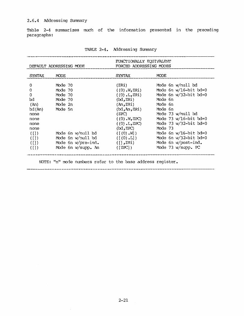
2.6.4 kJ.dressing Su11ffiary
Table 2-4 summarizes much of the information presented in the preceding paragraphs:
TABLE 2-4. kldressing Summary
FUNCTIONALLY EQUIVALENT DEFAULT ADDRESSING MODE FORCED ADDRESSING MODES
SYNTAX
0 0 0 bd (An) bd (An) none none none none ( []) ( []) ( []) ( [] )
MODE
Mode 70 Mode 70 Mode 70 Mode 70 Mode 2n Mode 5n
Mode 6n w/null bj
Mode 6n w/null bd Mode 6n w/pre-ind. Mode 6n w/supp. An
SYNTAX
(ZRi) ( (0) .W,ZRi) ( ( 0) • L, ZRi) (bd,ZRi) (An,ZRi) (b:3 ,An ,ZRi) (ZPC) ( (0) .W,ZPC) ( (0) .L,ZPC) (oo, ZPC) ([ (0) • W]) ([(0).L]) ( [] ,ZRi) ( [ZPC])
MODE
Mode 6n w/null bd Mode 6n w/16-bit bd=O Mode 6n w/32-bit bd=O Mode 6n Mode 6n Mode 6n Mode 73 w/null bd Mode 73 w/16-bit lrl=O Mode 73 w/32-bit bd=O Mode 73 Mode 6n w/16-bit bd=O Mode 6n w/32-bit bd=O Mode 6n w/post-ind. Mode 73 w/supp. P2
NOTE: "n" mode numbers refer to the base address register.
2-21

2.7 NOTES ON ADDRESSING OPTIONS
By default, the assembler resolves all forward references by using the longer form of the effective address in the operand reference. The programner may override this default by specifying OPT FRS, which designates that forward absolute references should be short, or OPT BRB (or BRS), designating that forward relative branches should use the shorter (8-bi t) displacement format. For the MC68020, OPT BRW can be used to force 16-bi t (rather than 32-bi t) displacements on forward branches.
On an instruction which does not allow a size code, the current forward reference default format may be overridden (for that instruction only) by appending .s (short) or .L (long) to the instruction mnemonic. A similar override may be performed in the structured syntax control directives via the extent codes (see paragraph 6. 3 for further explanation) • No override is possible on instructions with size code specification. Notably, this override procedure is possible on the JMP and JSR instructions.
The shorter form of the effective address for relative branch instructions is an 8-bit displacement; the longer format is a 16-bit displacement. For absolute jumps, the shorter effective address is the 16-bit absolute short; the longer format is the 32-bit absolute long mode. In the case of forward references in either relative branches or absolute jumps, if the shorter format is directed and the longer format is later found necessary when the reference is resolved, an error will occur.
References to symbols already defined, whether absolute or relative, are resolved by the assembler into the appropriate effective address, unless .s or .L is forced on the instruction.
A short form may be forced by following the instruction mnemonic with .s.
Exa!lple:
BEQ.S LOO Pl If condition code 'EQ' (equal) is true, then branch to LOOPl (using the short form of the instruction) •
In this case, the instruction size is forced to one word. An error will be printErl if the operand field is not in the range of an 8-bit displacement.
Since 8-bit value fields are not relocated, a Bcc.S instruction, which branches to an XREF or other expression-required location, is not allowed. Such an instruction format results in an assembler error. A relative branch to a symbol known to be an XREF, or in a different section than the instruction, employs the longer (16-bit) displacement, with resolution done by the linkage editor.
2-22

Default actions of the assernbler have been chosen to minimize two common address mode errors:
a. Displacement range violations
Relative branch instructions (Bee, BRA, BSR) allow either 8-bit or 16-bit displacements fran the PC. On forward references in such instructions, the default action is to assume the 16-bit displacement (OPT BRW), which also allows resolution by the linkage Erlitor, should that prove necessary.
b. Inappropriate absolute short address
Absolute addresses may be short (16-bit) or long (32-bit}. On forward references with absolute effective address, the default action is to assume the long format (OPT FRL). The long form is also assumed on references to another section (unless it is a SECTION.S}, so that resolution by the linkage editor is assured.
Default conditions have been chosen to prevent errors by using addressing formats which ensure address resolution in the broadest range of conditions, at the expense of code efficiency. Each default may be overridden to improve efficiency or to create position independent code. Also, the current address size defaults (options FRL and FRS) may be overridden in certain cases on S?=cific instructions which do not allow size codes by appending .s or .L, as in JMP.S and JMP.L (JMP and JSR only).
The previous discussion assumed relative branches could not be 32 bits. This is not the case when using the t-e68020.
The resolution of operands into effective address modes (ignoring base register addressing) is summarized in the Tables 2-5 through 2-10.
TABLE 2-5. Operand Resolution
INSTRUCTION FOLLOWS
OPERAND TYPE
Known location (backward in pass 1)
Unknown location (forward}
External reference
SECTION
See Table 2-6
See Table 2-8
See Table 2-9
2-23
ORG
See Table 2-7
See Table 2-8
See Table 2-10

TABLE 2-6. Known* Location of Operand & Instruction Follows SECTION
OPTION IN EFFECT WHEN
OPERAND INSTRUCTION REFERENCE OCCURRED EFFECTIVE ADDRESS MODE
PC relative (resolved by linkage editor
PCS if operand & instructions are in different SECTIONS)
IF displacement > 16-bit THEN error
Simple relocation
IF operand and instruction in same SECTION and
NO PCS displacement <= 16-bit (default) THEN PC relative
ELSE IF operand defined in SECTION.S
THEN absolute short ELSE absolute long
(resolved by linkage editor)
Complex relocation (Any) Absolute long
Absolute Absolute short or absolute (ORG) (Any) long depending on the value
of the operand
* Label defined before instruction which references it (in pass 1).
2-24
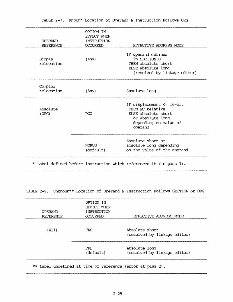
TABLE 2-7. Known* Location of Operand & Instruction Follows ORG
OPERAND REFERENCE
Simple relocation
Complex relocation
Absolute (ORG)
OPTION IN EFFECT WHEN INSTRUCTION OCCURRED
(Any)
(Any)
PCO
NOPCO (default)
EFFECTIVE ADDRESS MODE
IF operand defined in SECTION. S
THEN absolute short ELSE absolute long
(resolved by linkage editor)
Absolute long
IF displacement <= 16-bit THEN PC relative ELSE absolute short
or absolute long depending on value of operand
Absolute short or absolute long depending on the value of the operand
* Label defined before instruction which references it (in pass 1).
TABLE 2-8. Unknown** Location of Operand & Instruction Follows SECTION or ORG
OPERAND REFERENCE
(All)
OPTION IN EFFECT WHEN INSTRUCTION OCCURRED
FRS
FRL (default)
EFFECTIVE ADDRESS MODE
Absolute short (resolved by linkage editor)
Absolute long (resolved by linkage editor)
** Label undefined at time of reference (error at pass 2) •
2-25

TABLE 2-9. External Reference & Instruction Follows SECTION
OPERAND REFERENCE
XREF with SECTION designation
Example: XREF 2:Ll
XREF without SECTION designation
Example: XREF Ll
OPTION IN EFFECT WHEN INSTRUCTION OCCURRED
PCS
NO PCS (default)
(Any)
FRS
FRL (default)
2-26
EFFECTIVE ADDRESS MODE
PC relative (resolved by linkage editor)
IF operand defined in SECTION.S or XREF.S
THEN absolute short ELSE absolute long
(resolved by linkage editor)
IF operand defined with XREF.S
THEN absolute short ELSE (see below)
(resolved by linkage editor)
Absolute short (resolved by linkage editor)
Absolute long (resolved by linkage editor)
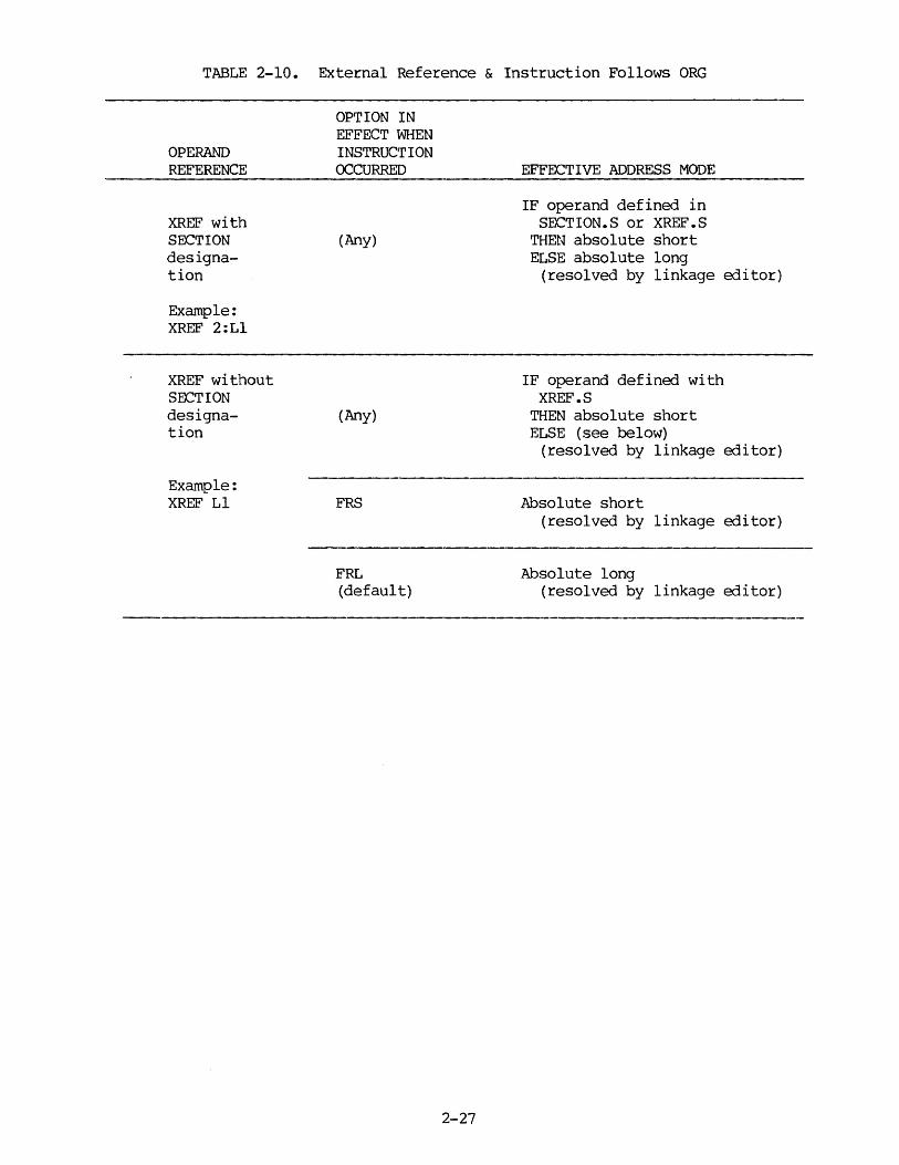
TABLE 2-10. External Reference & Instruction Follows ORG
OPERAND REFERENCE
XREF with SECTION designation
Example: XREF 2:Ll
XREF without SECTION designation
Example: XREF Ll
OPTION IN EFFECT WHEN INSTRUCT ION OCCURRED
(Any)
(Any)
FRS
FRL (default)
2-27
EFFECTIVE ADDRESS MODE
IF operand defined in SECTION.S or XREF.S
THEN absolute short ELSE absolute long
(resolved by linkage editor)
IF operand defined with XREF.S
THEN absolute short ELSE (see below)
(resolved by linkage editor)
Absolute short (resolved by linkage editor)
Absolute long (resolved by linkage editor)
2.8 SYMBOLS AND EXPRESSIONS
2.8.1 Symbols
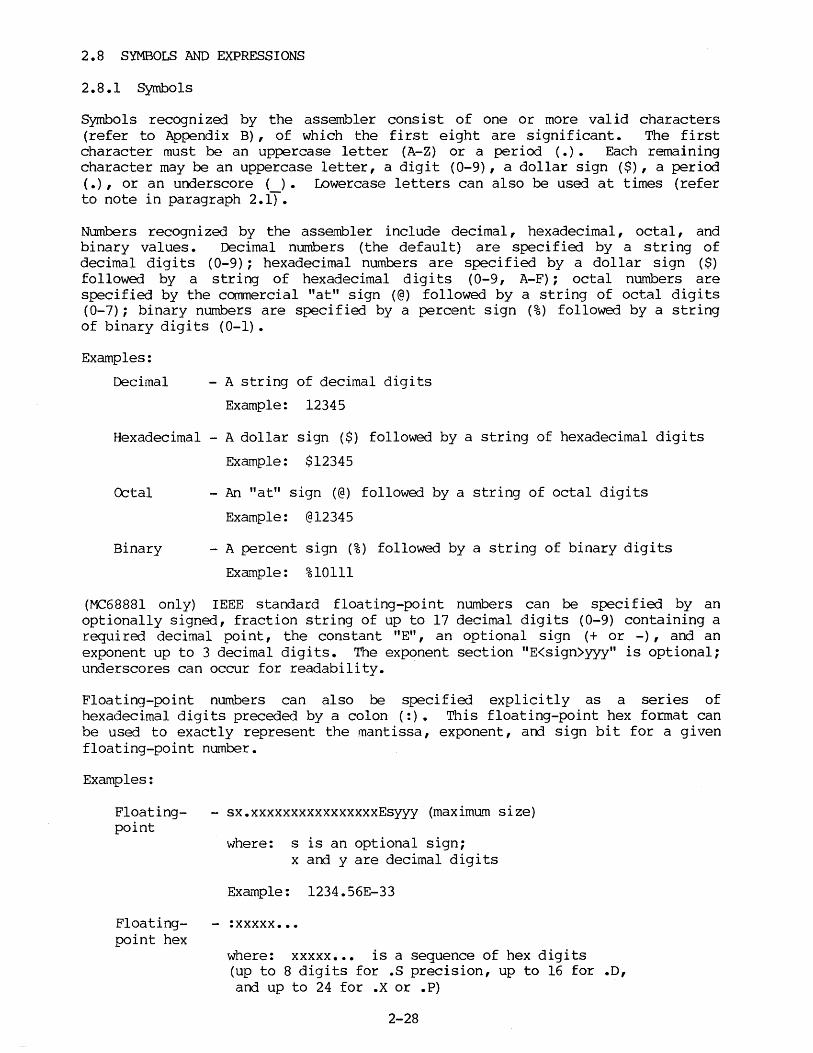
Symbols recognized by the assembler consist of one or more valid characters (refer to Appendix B) , of which the first eight are significant. The first character must be an uppercase letter (A-Z) or a period (.) • Each remaining character may be an uppercase letter, a digit (0-9), a dollar sign ($), a period (.), or an underscore ( ) • Lowercase letters can also be used at times (refer to note in paragraph 2.1).
Numbers recognized by the assembler include decimal, hexadecimal, octal, and binary values. Decimal numbers (the default) are specified by a string of decimal digits (0-9); hexadecimal numbers are specified by a dollar sign ($) followed by a string of hexadecimal digits (0-9, A-F); octal numbers are specified by the commercial "at" sign (@) followed by a string of octal digits (0-7); binary numbers are specified by a percent sign (%) followed by a string of binary digits (0-1).
Examples:
Decimal - A string of decimal digits
Example: 12345
Hexadecimal - A dollar sign ($) followed by a string of hexadecimal digits
Example: $12345
Octal
Binary
- An "at" sign (@) followed by a string of octal digits
Example: @12345
- A percent sign (%) followed by a string of binary digits
Example: %10111
(MC68881 only) IEEE standard floating-point numbers can be specified by an optionally signed, fraction string of up to 17 decimal digits (0-9) containing a required decimal point, the constant "E", an optional sign (+ or -) , and an exponent up to 3 decimal digits. The exponent section "E<sign>yyy" is optional; underscores can occur for readability.
Floating-point numbers can also be specified explicitly as a series of hexadecimal digits preceded by a colon (:). This floating-point hex format can be used to exactly represent the mantissa, exponent, and sign bit for a given floating-point number.
Examples:
Floating- - sx.xxxxxxxxxxxxxxxxEsyyy (maximum size) point
where: s is an optional sign; x and y are decimal digits
Exa~ple: 1234.56E-33
Floating- - :xxxxx ••• point hex
where: xxxxx ••• is a sequence of hex digits (up to 8 digits for .s precision, up to 16 for .D, and up to 24 for .X or .P)
2-28

One or more ASCII characters enclosed by apostrophes (') constitute an ASCII string. ASCII strings are left-justified and zero-filled (if necessary), whether stored or used as imnediate operands. This left justification will be to a word boundary if one or two characters are specified, or to a longword boundary if the string contains more than two characters. (In order to specify an apostrophe within a literal or string, two successive apostrophes must appear where the single apostrophe is intended to appear.)
Examples: DC.L OC.L oc.w OC.L
'ABCD' " '79' '*' 'I"M'
2.8.2 Symbol Definition Classes
Symbols may be differentiated by usage into two general classes. Class 1 symbols are used in the operation field of the instruction (refer to paragraph 2.4 for field definitions); Class 2 symbols occur in the label and operand fields of the instruction. Assembler directives, instruction mnemonics, and macro names comprise Class 1 symbols; user-defined labels and register mnemonics are included in Class 2 symbols.
A Class 1 symbol may be redefined and used independently as a Class 2 symbol, arrl vice versa. As long as each symbol is used correctly, no conflict will result from the existence of two symbols of different classes with the same name. For exa~ple, the following is a legal instruction sequence:
ADD Dl,ADD
ADD OS 2
By its usage as a Class 1 symbol, the first "ADD" is recognized as an instruction mnemonic; likewise, the second ADD is recognized as a Class 2 symbol identifying a reserved storage area. The assembler differentiates a Class 1 symbol from a Class 2 symbol with the same name, thereby allowing two symbol table entries with the same name but different class.
Macro labels are a special case because the same symbol will appear as the label (Class 2) in the MACRO definition and, subsequently, as an operation code mnemonic (Class 1) in invocation of that same macro. Macro labels are defined to be Class 1 symbols; their presence in the label field of a MACRO directive is ignored as a Class 2 symbol. Therefore, macro names may be redefined as Class 2 symbol~ without conflict.
A symbol may not be redefined within the same class. For example, ADD (reserved Class 1 symbol) may not be redefined as a macro label (also Class 1), nor may "AS" (reserved Class 2 symbol) be redefined as a statement or storage location label (also Class 2). A reserved symbol may be used only within its own class.
2-29
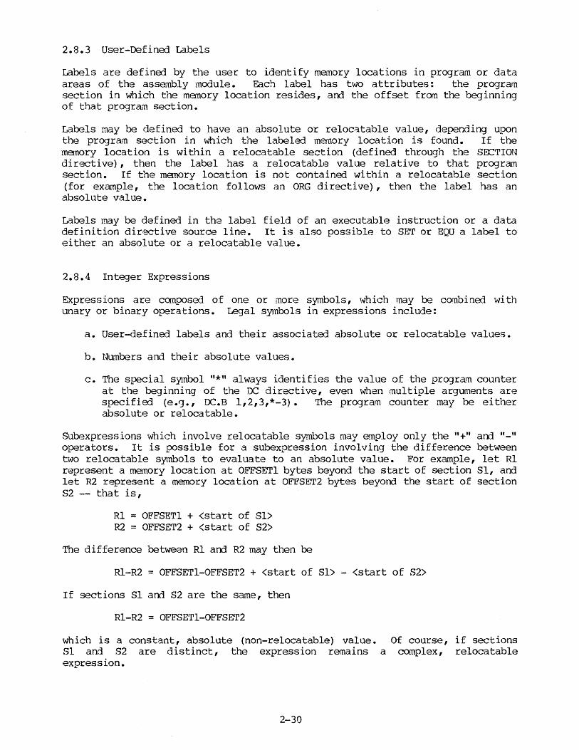
2.8.3 User-Defined Labels
Labels are defined by the user to identify memory locations in program or data areas of the assembly module. Each label has two attributes: the program section in which the manory location resides, and the offset from the beginning of that program section.
Labels may be defined to have an absolute or relocatable value, depending upon the progra.11 section in which the label<~ memory location is found. If the memory location is within a relocatable section (defined through the SECTION directive) , then the label has a relocatable value relative to that program section. If the menory location is not contained within a relocatable section (for exa11ple, the location follows an ORG directive), then the label has an absolute value.
Labels may be defined in the label field of an executable instruction or a data definition directive source line. It is also possible to SET or EQU a label to either an absolute or a relocatable value.
2.8.4 Integer Expressions
Expressions are canposed of one or more symbols, which may be combined with unary or binary operations. Legal symbols in expressions include:
a. User-defined labels and their associated absolute or relocatable values.
b. Numbers and their absolute values.
c. The special symbol "*" always identifies the value of the program counter at the beginning of the DC directive, even when multiple arguments are specified (e.g., OC.B 1,2,3,*-3). The program counter may be either absolute or relocatable.
Subexpressions which involve relocatable symbols may employ only the "+" and "-" operators. It is possible for a subexpression involving the difference between two relocatable symbols to evaluate to an absolute value. For example, let Rl represent a memory location at OFFSETl bytes beyond the start of section Sl, and let R2 represent a memory location at OFFSET2 bytes beyond the start of section S2 -- that is,
Rl = OFFSET! + <start of Sl> R2 = OFFSET2 + <start of 82>
The difference between Rl and R2 may then be
Rl-R2 = OFFSET1-0FFSET2 + <start of Sl> - <start of 82>
If sections Sl and 82 are the same, then
Rl-R2 = OFFSET1-0FFSET2
which is a constant, absolute {non-relocatable) value. Of course, if sections Sl and 82 are distinct, the expression remains a complex, relocatable expression.
2-30
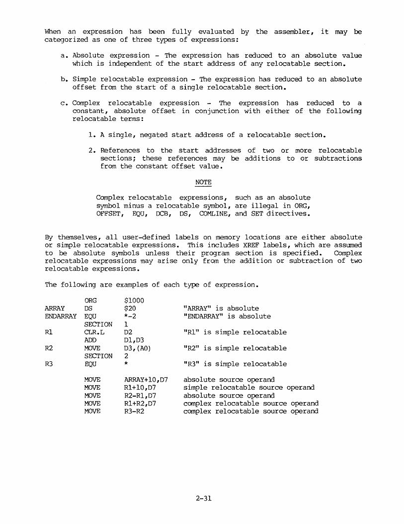
When an expression has been fully evaluated by the assembler, it may be categorized as one of three types of expressions:
a. Absolute expression - The expression has reduced to an absolute value which is independent of the start address of any relocatable section.
b. Simple relocatable expression - The expression has reduced to an absolute offset from the start of a single relocatable section.
c. Complex relocatable expression The expression has reduced to a constant, absolute offset in conjunction with either of the following relocatable terms:
1. A single, negated start address of a relocatable section.
2. References to the start addresses of two or more relocatable sections; these references may be additions to or subtractions from the constant offset value.
NOTE
Complex relocatable expressions, such as an absolute symbol minus a relocatable symbol, are illegal in ORG, OFFSET, EQU, ~B, OS, COMLINE, and SET directives.
By themselves, all user-defined labels on memory locations are either absolute or simple relocatable expressions. This includes XREF labels, which are assumed to be absolute symbols unless their program section is specified. Complex relocatable expressions may arise only from the addition or subtraction of two relocatable expressions.
The following are examples of each type of expression.
ARRAY END ARRAY
Rl
R2
R3
ORG DS EQU SECTION CLR.L ADD MOVE SECTION EQU
MOVE MOVE MOVE MOVE MOVE
$1000 $20 *-2 1 02 Dl,03 03, (AO) 2
* ARRAY+l0,07 Rl+l0,07 R2-Rl,D7 Rl+R2,D7 R3-R2
"ARRAY" is absolute "ENDARRAY" is absolute
"Rl" is simple relocatable
"R2" is simple relocatable
"R3" is simple relocatable
absolute source operand simple relocatable source operand absolute source operand complex relocatable source operand complex relocatable source operand
2-31
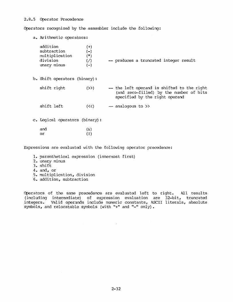
2.8.5 Operator Precedence
Operators recognized by the assembler include the following:
a. Arithmetic operators:
addition subtraction multiplication division unary minus
(+) (-) (*) (/) (-)
b. Shift operators (binary) :
shift right (>>)
shift left («)
c. Logical operators (binary):
and or
(&) ( ! )
-- produces a truncated integer result
the left operand is shifted to the right (and zero-filled) by the number of bits specified by the right operand
analogous to >>
Expressions are evaluated with the following operator precedence:
1. parenthetical expression (innermost first) 2. unary minus 3. shift 4. and, or 5. multiplication, division 6. addition, subtraction
Operators of the sa.'1le precedence are evaluatoo left to right. All results (including intermediate) of expression evaluation are 32-bit, truncated integers. Valid operands include nurneric constants, ASCII literals, absolute symbols, and relocatable symbols (with "+" and "-" only).
2-32
2.9 REGISTERS
The MC68000 has sixteen 32-bit registers (D0-07, AO-A7) in addition to a 24-bit program counter and 16-bit status register.
Registers D0-07 are used as data registers for byte, word, and longword operations. Registers AO-A7 are used as software stack pointers and base address registers; they may also be used for word and longword data operations. All 16 registers may be used as index registers.
Register A7 is used as the system stack pointer. (The MPU actually provides two hardware stack pointers, depending upon whether the instruction is executing in the supervisor or user state. Stack pointers and the supervisor/user states are explained under "Stacks and Queues" and "Privilege States" in the M68000 16/32-Bit Microprocessor Programmer's Reference Manual.)
(MC68010 only) The MC68010 has an additional 32-bit register (VBR) and two 3-bit registers (SFCR and DFCR) • The contents of the VBR are added to the previously-calculated vector offset, during exception processing, to produce the actual vector location. The 3-bi t registers allow supervisor access to other address spaces via MOVES, supplying function codes in the SFCR for the read cycle(s) from the effective address location, or supplying function codes in the DFCR for the write cycle(s) to the effective address location, respectively.
(MC68020 only) The MC68020 has four additional 32-bit registers. Two of these registers are used as stack pointers (MSP and ISP) • The other two are used as cache registers (CACR and CAAR). MSP (master stack pointer) is active whenever both the "S" and "M" bi ts of the status register are set (supervisor state). ISP (interrupt stack pointer) is active whenever the "S" bit is set but not the "M" bit (interrupt state). USP (user stack pointer) is active whenever the "S" bit is 0 (user state) • The cache registers support the onboard instruction cache of the MC68020 and can be accessed only in the supervisor state.
(MC68020 only) The assembler also provides 17 pseudo register names for the MC68020. These are the suppressed address registers used in various MC68020 addressing modes. Each register represents a content value of zero:
ZAO-ZA7 ZDO-ZD7 ZPC
Suppressed address registers Suppressed data registers Suppressed program counter
(MC68881 only) The MC68881 floating-point co-processor provides eight 80-bi t registers and three 32-bi t registers. The 80-bi t registers are the floating point data registers, FP0-FP7, that serve as destinations for most floating point operations. The 32-bit registers are the system registers STATUS, CONTROL, and IADDR.
The following register mnemonics are recognized by the assembler:
00-07
ZDO-ZD7
AO-A7
ZAO-ZA7
A7, SP
Data registers.
Suppressed data registers (refer to paragraph 2.6.3 (MC68020 only))
Address registers.
Suppressed address registers (refer to paragraph 2.6.3 (MC68020 only))
Either mnemonic represents the system stack pointer of the active system state.
2-33
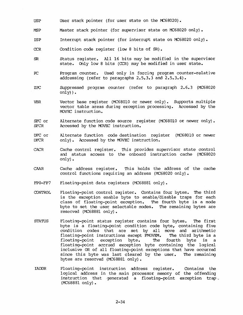
USP User stack pointer (for user state on the 11268020).
MSP Master stack pointer (for supervisor state on M:!68020 only) •
ISP Interrupt stack pointer (for interrupt state on 11268020 only) •
CCR Corrlition code register (low 8 bits of SR).
SR Status register. All 16 bits may be modified in the supervisor state. Only low 8 bits (CCR) may be modified in user state.
ZPC
VBR
SFC or SFCR
DFC or DFCR
CACR
CMR
FPO-FP7
CONTROL
STATUS
IADDR
Program counter. Used only in forcing program counter-relative addressing (refer to paragraphs 2.5.3.3 and 2.5.3.4).
Suppressed program counter (refer to paragraph 2.6.3 (MC68020 only)).
Vector base register (MC68010 or newer only). Supports multiple vector table areas during exception processing. Accessed by the MO\!El':: instruction.
Alternate function code source register (MC68010 or newer only). Accessed by the MOvrx:= instruction.
Alternate function code destination register (MC68010 or newer only) • Accessed by the MOV~ instruction.
Cache control register. arrl status access to only).
This provides supervisor state control the onboard instruction cache (MC68020
Cache address register. This holds the address of the cache control functions requiring an address (MC68020 only).
Floating-point data registers (MC68881 only) •
Floating-point control register. Contains four bytes. The third is the exception enable byte to enable/disable traps for each class of floating-point exception. The fourth byte is a mode byte to set the user selectable modes. The remaining bytes are reserved (MC68881 only) •
Floating-point status register contains four bytes. The first byte is a floating-point condition code byte, containing five corrlition codes that are set by all move and arithmetic floating-point instructions except FMOVEM. The third byte is a floating-point exception byte. The fourth byte is a floating-point accrued exception byte containing the logical inclusive OR of all floating-point exceptions that have occurred since this byte was last cleared by the user. The ranaining bytes are reserved (MC68881 only) •
Floating-point instruction crldress register. Contains the logical address in the main processor manory of the of fendifl9 instruction that generated a floating-point exception trap .. (MC68881 only) •
2-34

2.10 INSTRUCTION MNEMONICS
The instruction operations described in paragraphs 2 .10.1 through 2 .10.12 are used by the assembler for MC68000, MC68010, arrl MC68020. Paragraphs 2.10.13 and 2.10.14 however, describe instructions which are valid only for the MC68010 and MC68020 microprocessors. Paragraphs 2.10.15 through 2.10.24 describe instructions which are valid only for the MC68020 microprocessor. Paragraphs 2.10.25 through 2.10.25.12 describe instructions which are valid only for the MC68881 floating-point co-processor.
NOTE
The M68000 Family Resident Structured Assembler has been implemented using the instructions described in this section. Differences found in the MC68020 32-Bit Virtual Memory Microprocessor Reference Manual or the MC68020 32-Bit Virtual Memory Microprocessor User's Manual will be resolved in the next revision.
2.10.1 Arithmetic Operations
The MC68000/MC68010/MC68020 instruction set includes the operations of add, subtract, multiply, arrl divide. Md and subtract are available for all data operand sizes. Multiply and divide may be signed or unsigned~ Operations on decimal data (BCD) include add, subtract, and negate. The general form is:
[label:]
Examples:
ADD.W
SUB.B
<operation>.<size> <source>,<destination>
Dl,D2
#5 I (Al)
Adds low order word of Dl to low order word of D2.
Subtracts value 5 from byte whose address is contained in Al.
On the MC68020, the signed and unsigned multi ply instructions can support a 32-bit multiplier arrl a 64-bit product using an alternate operand syntax. This is achieved by using two data registers. One data register, Dj, holds the multiplier before multiplication arrl the low-order longword of the product after multiplication. Another data register, Di, holds the high-order longword of the product after multiplication (Di must be different from Dj). The general formats are:
MUIS.L MULU.L
<ea>, [Di: ]Dj <ea>, [Di : ] Dj
(signed multiply) {unsigned multiply)
where : is a required delimiter.
The signed and unsigned divide instructions on the MC68020 have been similarly expanded to support a 64-bit dividend, a 32-bit quotient, and a 32-bit renainder. This is achieved by using two data registers to hold the dividend before division arrl to separately hold the quotient and remainder after division. Data register Di thus holds the high-order longword of the dividend before division and the remairrler after division. Data register Dj holds the low-order longword of the dividend before division and the quotient after division. If a single data register Dj is specified or Di equals Dj, it is to be used as both the high-order and low-order 32 bits of the dividend for the divide, arrl the 32-bit quotient of the division is returned in it. No remainder is returned in this case. The general formats are:
DIVS.L DIVU.L
<ea>, [Di : ] Dj <ea>, [Di: ]Dj
{signed division) {unsigned division)
2-35

2.10.2 MOVE Instruction
The MOVE instruction is used to move data between registers and/or memory. The general form is:
MOVE.<size> <source>,<destination>
where:
<size> = B, W, or L
Examples:
MOVE Dl,02
MOVE.L XYZ,DEF
MOVE.W #'A' ,ABC
MOVE ADDR,A3
Moves low order word of Dl into low order word of D2.
Moves longword addressed by XYZ into longword addressed by DEF.
Moves word with value of $4100 into word addressed by ABC.
Moves word addressed by ADDR into low order word of A3.
2-36
2.10.3 Compare and Check Instructions
The general formats of the compare and check instructions are:
CMP.<size>
CHK <bounds>,<register>
where operand1 is compared to operand2 by the subtraction of operandi from operand2 without altering operandi or operand2.
The MC68020 allows the check instruction to have a longword size:
CHK.<size> <ea>,Dn
where:
<size> = W (default) or L
On the MC68020, the CMPI instruction allows any data addressing mode other than irrmediate for the specified effective address location.
Condition codes resulting from the execution of the compare instruction are set so that a "less than" condition means that operand2 is less than operandi, and "greater than" means that operand2 is greater than operandi.
The CHK instruction will cause a system trap if the register contents are less than zero or greater than the value specified by "bounds".
Examples:
CMP.L ADDR,Dl
CHK (AO) ,03
Compares longword at location ADDR with contents of oi, setting condition codes accordingly.
Compares word whose address is in AO with low order word of D3; if check fails (see text) , a system trap is initiated.
2.10.4 Logical Operations
Logical operations include AND, OR, EXCLUSIVE OR, NOT, and two logical test operations. These functions may be done between registers, between registers and memory, or with immediate source operands. The general form is:
<operation>.<size>
where:
<size> = B, w, or L
Example:
AND oi,02
<source>,<destination>
Low order word of D2 receives logical 'and' of low order words in Dl and 02.
The destination may also be the status register (SR) or the condition code register (CCR) in the case of the ANDI instruction.
2-37

2.10.5 Shift Operations
Shift operations include arithmetic and logical shifts, as well as rotate and rotate with extend. All shift operations may be either fixed with the shift count in an immediate field or variable with the count in a register. Shifts in memory of a single-bit position left or right may also be done. The general form is:
<operation>.<size>
where:
<size> = B, W, or L
Examples:
LSL.W #5,03
ASR (A2)
ROXL.B 03,02
2.10.6 Bit Operations
<count>,<operand>
Performs a left, logical shift of low order word of 03 by 5 bits; .w is optional (default).
Performs a right, arithmetic shift of word whose address is contained in A2; because this is a memory operand, the shift is only 1 bit.
Performs a left rotation with extend bit of low order byte of D2; shift count is contained in 03.
Bit operations allow test and modify combinations for single bits in either an 8-bi t operand for memory destinations or a 32-bi t operand for data register destinations. The bit number may be fixed or variable. The general form is:
<operation> <bitno>,<operand>
where:
<size> = B or L
Examples:
BCLR #3,XYZ(A3) Clears bit number 3 in byte whose address is given by address in A3 plus displacement of XYZ.
BCHG Ol,02 Tests a bit in 02, reflects its value in condition code Z, and then changes value of that bit; bit number is specified in 01.
Under Mask3 of the MC68000 chip, the instructions BCLR, BSET, and BTST have 8-bit memory operands; under Mask2 they had 16-bit memory operands. To enable users who wrote programs under Mask2 -- using BCHG, BCLR, BSET, and BTST instructions -- and to reassemble these programs under Mask3, the replacement instructions BCHGW, BCLRW, BSETW, and BTSTW are provided. These instructions align the destination operand at the next higher byte when bits 0-7 are accessed (thus functioning under Mask3 exactly as BCHG, BCLR, BSET, and BTST functioned under Mask2). In making the change, replace only the instruction mnemonic; no change is required to the operand field.
2-38

2.10.7 Conditional Operations
Condition codes can be used to set and clear data bytes. The general form is:
Sec <location>
where "cc" may be one of the following condition codes:
CC or HS GE CS or LO GT EQ HI F LE
Example:
SNE (AS)+
r.s LT MI NE
PL T vc vs
If condition code NE (not equal) is true, then set byte whose address is in AS to l's; otherwise, set that byte to O's; increment A5 by 1.
2-39
2.10.8 Branch Operations
Branch operations include an unconditional branch, a branch to subroutine, and 14 conditional branch instructions. The general form is:
<operation>.<extent> <location>
Examples:
BRA BSR
Bcc.S
TAG SUB DO
NEXT
Unconditional branch to the address TAG. Branch to subroutine SUBDO.
Short branch to NEXT on condition "cc", which may be one of the following condition codes (note that T and F are not valid condition codes for conditional branch):
CC or HS Gr cs or LO HI EQ LE GE LS
LT MI NE PL
vc vs
All conditional branch instructions use PC-relative addressing only and may be either one-word or two-word instructions. The corresponding displacement ranges are:
one-word two-word
-128 ••• +127 bytes -32768 ••• +32767 bytes
(8-bit displacement) (16-bit displacement)
Forward references in branch instructions use the longer format by default (OPT BRW) • The default may be changed to the shorter format by specifying OPT BRS or OPT BRB. The default extent may be overridden for a single branch operation by appending appropriate extent codes to the instruction -- for example:
BRA.S LAB
A branch instruction with a byte displacement must not reference the statement which irrmediately follows it. This would result in an 8-bit displacement value of O, which is recognized by the assembler as an error condition.
Example (illegal) :
BEQ.S LABl MOVE
LABl #1,DO
LABl is the next memory word and, thus, generates an error.
The MC68020 allows three sizes of offsets: byte ( .B or .S) , word ( .W), and longword (. L) • These provide byte, 2-byte, and 4-byte offsets, respectively. Compatibility with the old word ( .L) sizes is available by using the new OPT OLD directive (refer to paragraph 3.5.2.10). The default offset size is still word (two bytes). Branch sizes can also be forced with several new force branch size directives: BRB or BRS (generates 8-bit defaults), BRW (generates 16-bi t defaults) , BRW (generates 16-bi t defaults), and BRL (generates 32-bi t defaults) (refer to paragraph 3.5.2.10). These new branching sizes allow the following:
Bee. <size> BRA. <size> BSR. <size>
where:
<label> <label> <label>
<size> = B (or S), W, or L
2-40

2.10.9 Jump Operations
Jump operations include a jump to subroutine and an unconditional jump. The general form is:
<operation>.<extent> <ea>
Examples:
JMP
JMP.L
JSR
4 (A7)
NEXT
SUB DO
Unconditional jump to the location 4 bytes beyond the address in A7.
Long (absolute) jump to the address NEXT.
Jump to subroutine SUBDO.
Forward references to a label will use the long absolute address format by default (OPT FRL). The default may be changed to the shorter format by specifying OPT FRS. The default extent may be overridden on a single jump operation to a label by appending S or L as an extent code for the instruction.
2.10.10 DBcc Instruction
This instruction is a looping primitive of three parameters: condition, data register, and label. The instruction first tests the condition to determine if the termination condition for the loop has been met and, if so, no operation is performed. If the tennination condition is not true, the data register is decremented by one. If the result is -1, execution continues with the next instruction. If the result is not equal to -1, execution continues at the location indicated by label. Label must be within a 16-bit displacement. The general fonnat of the instruction is:
DBcc <data register>,<label>
where:
"cc" may be one of the following condition codes:
CC or HS GE CS or LO Gr EQ HI F LE
Examples:
LABl NOP DBGT DBLE DBT DBF
LAB2 NOP
LS LT MI NE
DO,LABl Dl,LAB2 02,LABl D3,LAB2
PL T vc vs
2-41

2.10.11 Load/Store Multiple Registers
This instruction allows the loading and storing of multiple registers. Its general format is:
MOVEM.<size> <registers>,<location> (register to memory)
MOVEM.<size> <location>,<registers> (memory to register)
where:
<size> may be either W (default) or L.
The <registers> operand may assume any combination of the following:
Rl/R2/R3, etc. , means Rl arrl R2 arrl R3
Rl-R3, etc., means Rl through R3
When specifying a register range, A and D registers cannot be mixed; e.g., AO-AS is legal, but AO-DO is not.
The order in which the registers are processed is independent of the order in which they are specified in the source line; rather, the order of register processing is fixed by the instruction format. For further details, refer to the MOVEM instruction in the MC68000 16/32-Bit Microprocessor Prograrrrner's Reference Manual.
Examples:
MOVEM (A6)+,Dl/D5/D7
MOVEM.L A2-A6,-(A7)
MOVEM (A7)+,Al-A3/Dl-D3
MOVEM.L Al/A2/A3,REGSAVE
Load registers Dl, DS, and D7 from three consecutive (sign-extended) words in memory, the first of which is given by the address in A6; A6 is incremented by 2 after each transfer.
Store registers A2 through A6 consecutive longwords in memory; decremented by 4 (because of .L) ;
in five A7 is A6 is A7 is
address stored at the address in A7; decremented by 4; AS is stored at the in A7, etc.
Loads registers Dl, 02, D3, Al, A2, A3 in order from the six consecutive (sign-extended) words in memory, starting with the address in A7 and incrementing A7 by 2 at each step.
Store registers Al, A2, A3 in three consecutive longwords starting with the location labeled REGSAVE.
2-42
2.10.12 Load Effective Address
This instruction allows computation and loading of the effective address into an address register. The general format is:
LEA <operand>,<register>
Example:
LEA XYZ(A2,D5) ,Al Load Al with effective address specified by the first operand. Refer to paragraph 2.5.2.5 for an explanation of addressing mode "Address Register Indirect With Index".
2.10.13 Move to/from Control Register
(MC68010 or newer only) With this instruction, the specified control register is copie:l to the speci fiea general register, or the specified general register is copied to the specifiea control register. This is always a 32-bit transfer, even though the control register may be implemented with fewer bits. Unimplanented bits read as zeros. The general format is:
MOVEC MOVOC
Examples:
MOVOC
MOVEC
MOVOC
<control register>,<register> <register>,<control register>
VBR,AO
D7 ,SFC
DFC,DO
Copies contents of vector base register to register AO.
Copies contents of register D7 to the source function code register (3 bits).
Copies contents of destination function code register to register DO (3 bits; zero filled).
MOVEC.L USP,D7 Copies user stack pointer to register D7.
(MC68020 only) Four additional <control register> values are recognized for the MC68020:
CACR: CAAR: MSP: ISP:
Cache control register Cache address register Master stack pointer Interrupt stack pointer
NOTE
If the instruction is usErl without setting the processor type in this carunarrl line or in the OPT P=68XXX, then an error is generated.
2-43

2.10.14 Move to/from Address Space
(MC68010 or newer only.) Moves a byte, word, or longword from the specified general register to a location within the address space determined by the DFC register, or moves a byte, word, or longword from a location within the address space determined by the SFC register to the specified general register. Note that with a byte operation size specified, the address register direct mode is not allowed.
General format:
MOVES <ea>,<register> MOVES <register>,<ea>
Examples:
MOVES.W (A2)+,D2
MOVES A4,LABEL
MOVES 2222,A2
Moves a word at the address contained in register A2 to register 02 and then increments A2 by 2.
Moves the lower word of register A4 to the address of LABEL.
Moves one word of data beginning at address 2222 to register A2.
NOTE
If the instruction is used without setting the processor type in the canmarrl line or in the OPT P=68XXX, then an error is generated.
2.10.15 Bit Fields arrl Instructions (MC68020 only)
NOTE
The instructions in paragraphs 2.10.15 through 2.10.24 require that the processor type be set to 68020 in the command line or in the OPT P=68XXX directive. otherwise, an error is generated.
A bit field is a string of consecutive bits in a bit array. The address of the bit array is determined by the address of the byte containing bit 0 (the base address). Bit fields exteo:l in both directions from bit O and are assigned bit field numbers from 0 (the leftmost and most significant bit) to 7 (the rightmost arrl least significant bit). By this notation a preceding byte's least significant bit has a bit field number of 8. Instructions reference bit fields using two parameters: a bit field offset and a bit field width. A bit field offset is the bit field number of the leftmost bit in the field; its range is -2**31 to (2**31) - 1. The bit field width is the number of bits in the bit field; its range is 1 to 32.
2-44

2.10.15.1 , Single Operand Bit Field Instructions.
This section explains the following single operand bit fields: clear, set and test.
Complement Bit Field
complement,
Complements a bit field at the specified effective address location. Condition code fields are modified, depending on the value in the bit field before the complement. A bit field is selected by the bit field offset (the starting bit) and the bit field width (the number of bits included).
General format:
BFCHG <ea>{<offset>:<width>}
where:
{, : , and } are required delimiters; <offset> and <width> may be an immediate value or a data register DO-D7.
Example:
BFCHG LABEL{O:Dl} Complements the bit field at address LABEL from bit O to bit n - 1 where n is the value in Dl.
Clear Bit Field
Clears a bit field at a specified effective address location. Condition code fields are modified, depending on the value in the bit field before the clear. A bit field is selected by the bit field offset (the starting bit) and the bit field width (the number of bits included).
General format:
BFCLR <ea>{<offset>:<width>}
where:
{, . , and } are required delimiters; <offset> and <width> may be an immediate value or a data register D0-07.
Example:
BFCLR LABEL{Dl:8} Clears the bit field at address LABEL starting at the bit specified in Dl for 8 bits.
2-45
Set Bit Field
Sets all bits of a bit field at a specified effective address location. Condition code fields are modified, depending on the value in the bit field before the set. A bit field is selected by the bit field offset (the starting bit) and the bit field width (the number of bits included).
General format:
BFSET <ea>{<offset>:<width>}
where:
{, : , and } are required delimiters; <offset> and <width> may be an immediate value or a data register D0-07.
Example:
BFSET 2222{0:8} Sets one byte at address 2222 to all l's.
Test Bit Field
Sets condition codes according to the value in the bit field at the specified effective address location. A bit field is selected by the bit field offset (the starting bit) and the bit field width (the number of bits included). General format:
BFTST <ea>{<offset>:<width>}
where:
{, :, and } are required delimiters; <offset> and <width> may be an irrrnediate value or a data register D0-07.
Example:
BFTST (A2) {Dl:D2} Clears condition codes V and C; sets N and Z according to the bits of the bit field.
2-46

2.10.15.2 Double Operand Bit Field Instructions.
This section explains the following double operand bit fields: extract signed, extract unsigned, find first one, and insert.
Extract Bit Field Signed
The bit field at the specified effective address location is sign-extended to 32 bi ts and loaded into a data register. Condition code fields are modified, depending on the value in the bit field before the sign extension. A bit field is selectErl by the bit field offset (the starting bit) and the bit field width (the number of bits included).
General format:
BFEXTS <ea>{<offset>:<width>},Dn
where:
{, : , and } are required delimiters; <offset> and <width> may be an immediate value or a data register 00-07.
Example:
BFEXTS LABEL{0:8},Dl
Extract Bit Field Unsigned
The value of the byte at LABEL is sign-extended and then loaded into Ol.
The bit field at the specified effective address location is zero extended to 32 bits and loaded into a data register. Condition code fields are modified, depending on the value in the bit field before the zero extension. A bit field is selected by the bit field offset (the starting bit) and the bit field width (the number of bits included).
General format:
BFEXTU <ea>{<offset>:<width>},Dn
where:
{, : , and } are required delimiters; <offset> and <width> may be an imnediate value or a data register 00-07.
Example:
BFEXTU LABEL{0:8},Dl The value of the byte at LABEL is zero-extended and then loaded into Ol.
2-47
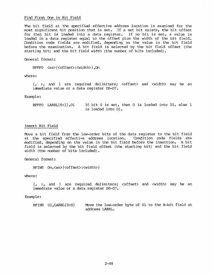
Find First One in Bit Field
The bit field at the specified effective address location is examined for the most significant bit position that is set. If a set bit exists, the bit offset for that bit is loaded into a data register. If no bit is set, a value is loaded in a data register equal to the offset plus the width of the bit field. Condition code fields are modified, depending on the value in the bit field before the examination. A bit field is selected by the bit field offset (the starting bit) and the bit field width (the number of bits included).
General format:
BFFFO <ea>{<offset>:<width>},Dn
where:
{, : , and } are required delimiters; <offset> and <width> may be an irrmediate value or a data register D0-07.
Example:
BFFFO LABEL{O:l},Dl
Insert Bit Field
If bit 0 is set, then 0 is loaded into Dl, else 1 is loaded into Dl.
Move a bit field from the low-order bits of the data register to the bit field at the specified effective address location. Condition code fields are modified, depending on the value in the bit field before the insertion. A bit field is selected by the bit field offset (the starting bit) and the bit field width (the number of bits included).
General format:
BFINS Dn,<ea>{<offset>:<width>}
where:
{, : , and } are required delimiters; <offset> and <width> may be an inmediate value or a data register D0-07.
Example:
BFINS Dl,LABEL{0:8} Move the low-order byte of Dl to the 8-bit field at address LABEL.
2-48

2.10.16 Check Instructions (MC68020 only)
Check arrl compare register instructions are discussed in the following paragraphs.
2.10.16.l Check Register Against Bounds. Check the value in register Rn against the lower- and upper-bound pair at the address of the specified effective ·address location. \Nhen signed comparisons . are made, the arithmetically smaller value should be taken as the lower bound. For unsigned comparisons, the logically smaller value should be taken as the lower bound. If the instruction size is byte (.B) or word (.W), only the low-order byte or word of a data register, respectively, is used for the comparison. When Rn is an address register, an instruction size of byte or word results in a sign extension of the bound operands before the comparison. If the register is out of bounds, exception processing is initiated and a vector number that references the CHK instruction exception vector is generated. Only control addressing modes are allowed.
General format:
CHK2.<size> <ea>,Rn
where:
<size> = B, W, or L
Example:
CHK2.B LABEL,Dl The instruction following this instruction is executed provided the value of the low-order byte of Dl is greater than the contents of LABEL and less than the contents of LABEL + 1.
2.10.16.2 Canpare Register Against Bounds. This has exactly the same functionality as CHK2, except that no exception processing will occur if the value in Rn is not within bounds.
General format:
CMP2 <ea>,Rn
2-49
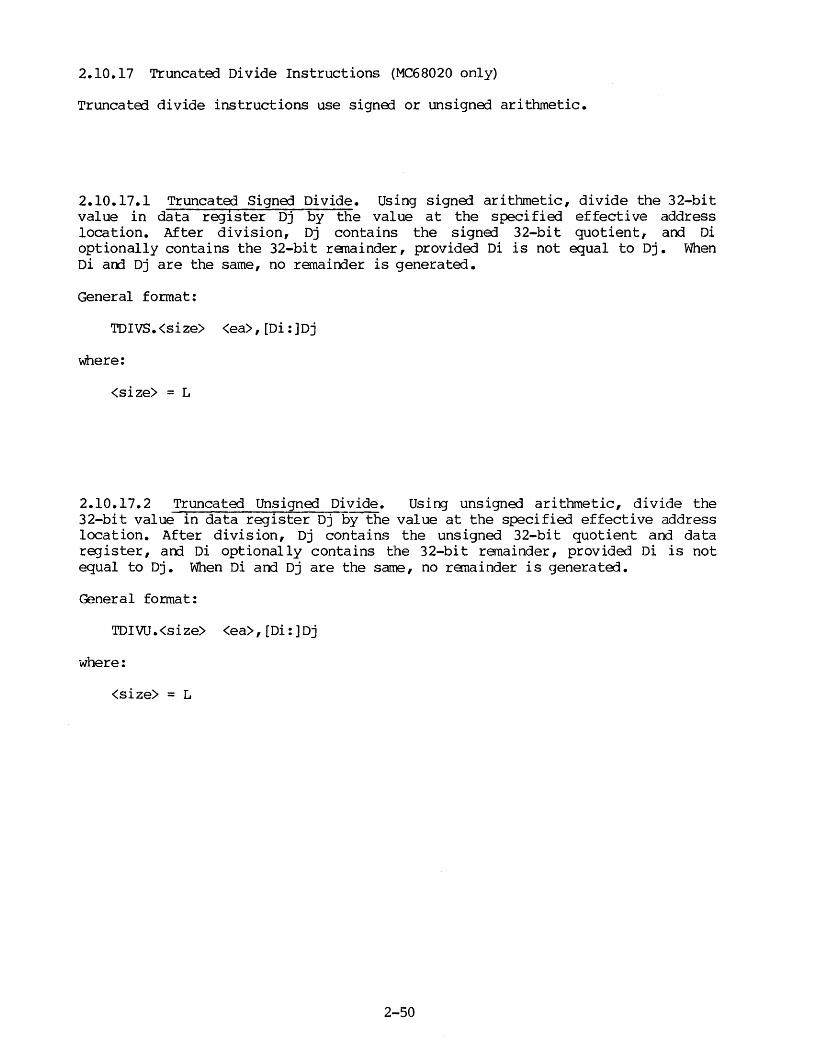
2.10.17 Truncated Divide Instructions (MC68020 only)
TruncatErl divide instructions use signed or unsigned arithmetic.
2.10.17.1 Truncated Signed Divide. Using signed arithmetic, divide the 32-bit value in data register Dj by the value at the specified effective address location. After division, Dj contains the signerl 32-bit quotient, and Di optionally contains the 32-bit renainder, provided Di is not equal to Dj. When Di arrl Dj are the same, no remainder is generated.
General format:
TDIVS.<size> <ea>,[Di:]Dj
where:
<size> = L
2.10.17.2 Truncated Unsigned Divide. Using unsigned arithmetic, divide the 32-bit value in data register Dj by the value at the specified effective address location. After division, Dj contains the unsigned 32-bit quotient and data register, arrl Di optionally contains the 32-bit remainder, provided Di is not equal to Dj. When Di and Dj are the same, no renainder is generated.
General fonnat:
TDIVU.<size> <ea>,[Di:]Dj
where:
<size> = L
2-50
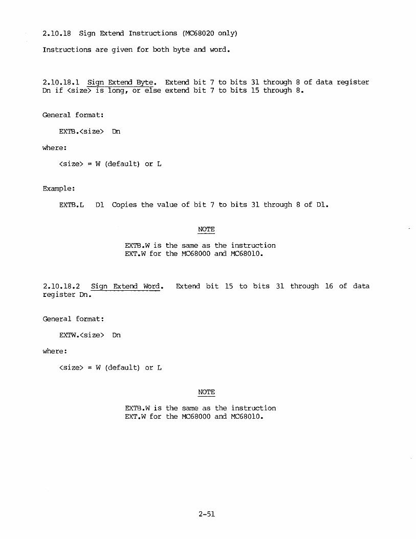
2.10.18 Sign Extend Instructions (MC68020 only)
Instructions are given for both byte and word.
2.10.18.1 Sign Extend Byte. Extend bit 7 to bits 31 through 8 of data register Dn if <size> is-fong, or else extend bit 7 to bits 15 through 8.
General fonnat:
EXTB.<size> Dn
where:
<size> = W (default) or L
Example:
EXTB.L Dl Copies the value of bit 7 to bits 31 through 8 of Dl.
NOTE
EXTB.W is the same as the instruction EXT.W for the MC68000 and MC68010.
2 .10 .18. 2 Sign Extend Word. Extend bit 15 to bi ts 31 through 16 of data register Dn.
General fonnat:
EXTW.<size> On
where:
<size> = W (default) or L
NOTE
EXTB.W is the same as the instruction EXT.W for the MC68000 and MC68010.
2-51

2.10.19 BCD Instructions (MC68020 only)
Instructions include both pack and unpack for BCD.
2.5.19.l Pack BCD. Pack the low four bits of each of two bytes into one byte. When a prerlecrement addressing mode is specifiErl, bits 3 through O of the two fetched consecutive source bytes are concatenated to form a packed byte, which is written to the destination. When both operands are data registers, bits 11 through 8 and bits 3 through 0 of the source register are concatenated to form the low-order packerl byte of the destination data register.
General format:
PACK -(Ay) ,-(Ax) PACK Dy,Dx
where:
Ay and Ax are address registers; Dy and ox are data registers
2.10.19.2 Unpack BCD. Two BCD digits in the source byte are stored in two consecutive bytes at the destination. When predecrement addressing is used, two BCD digits in the source byte are separately written to two consecutive bytes, and destination bits 7 through 4 are set to zero. When data registers are used, bits 7 through 4 and bits 3 through 0 of the source register are placed in bits 11 through 8 and bits 3 through O, respectively, of the destination register. All other bits of the destination register are set to zero.
General format:
UNPK -(Ay) ,-(Ax) UNPK Dy,Dx
where:
Ay and Ax are address registers; Dy and Dx are data registers.
2-52

2.10.20 Module Instructions (MC68020 only)
Both call and return are module instructions.
2.5.20.l Call Module. An external module descriptor resides at the specified effective address location. This module descriptor contains control information for entry into the associated module. A module frame, containing the current module state, is created on the top of the stack. The new module state is then loaded frcrn the external module descriptor. No condition codes are affected by this instruction. Only control-alterable addressing is allowed.
General format:
CALLM #ddd,<ea>
where:
ddd is the 8-bit number of bytes of arguments passed to the called module.
2.10.20.2 Return from Module. A previously saved module state, from a CALLM instruction, is reloaded from the top of the stack. A register Rn is used as the module data area pointer. If the module state includes a saved module data area pointer, register Rn is restored; else Rn is unchanged. No condition codes are affected.
General format:
RTM Rn
2.10.21 Trap on Condition Code (MC68020 only)
If the specified condition code is true, exception processing occurs. The vector number generated references the TRAPcc exception vector. The stacked program counter points to the next instruction. If the specified condition code is false, control passes to the next instruction in sequence. Any of the 16 condition codes may be referenced. Condition codes are not affected by this instruction. The #xxx parameter in the TPcc form allows a 16- or 32-bit value to be embedded within the instruction for reference in exception processing.
General format:
Tee TPcc.<size> #xxx
where:
<size> = W (default) or L
2-53

2.10.22 Compare and Swap with Operand (MC68020 only)
In the CAS instruction the specified effective address location is canpared to data register Dw. If operands match, the update operand in data register Dy is written to the specified effective address location. If operands do not match, Dw is loade1 with the contents at the specified effective address location.
In the CAS2 instruction, both Dwl and Dw2 must match the values in memory pointe1 to by ra_jisters Rzl and Rz2, respectively, in order that these memory values be updated by the contents of registers Dyl and Dy2. If both operands do not match, then Owl and Dw2 are loaded with the contents of memory pointed to by registers Rzl an:1 Rz2, respectively.
General formats:
CAS.<size> Dw,Dy,<ea>
CAS2.<size> Dwl:Dw2,Dyl:Dy2,(Rzl): (Rz2)
where:
<size> = B, W, or L
2.10.23 Breakpoint (MC68020 only)
The operation of this instruction is implementation-dependent. The processor will ask for the operation word which the breakpoint has replaced. If the operation word is furnished, the processor will execute that instruction and continue. If the operation word is not furnished, the processor will take an illegal instruction exception.
General format:
BKPT #<vector>
where:
#<vector> specifies the breakpoint for which the processor is to request the corresponding operation word. Value = 0 through 7.
2-54

2.10.24 The MC68881 Co-Processor Instructions (MC68881 only)
NOTE
The instructions in paragraphs 2.10.25.l and 2.10.25.2 require that the processor ty}?e be set to 68881 in the OPT directive or fran the canmarrl line. Otherwise, an error is generated.
At present, the assembler supports only the MC68881 co-processor. The assembler syntax that follows refers to opcodes for the MC68881, even though the MC68020 can support other co-processors which follow MC68881 protocols. Floating-point condition codes used in opcodes for the MC68881 are listed in Table 2-11.
TABLE 2-11. ~68881-SJ?ecific Floating-Point Condition Codes (fpcc)
TRAP ON UNORDERED
Gr Greater than
GE Greater than or equal
LT Less than
GL Greater or less than
LE Less than or equal
GLE Greater or less than
SEQ Equal
ST Always
NO TRAP ON UNORDERED
(X;T Greater than
OGE Greater than or equal
OLT Less than
OGL Greater or less than
OLE Less than or equal
OR OrderErl
EQ Equal
T Always
or equal
INVERSE
NGr Not greater than
NGE Not greater than or equal
NLT Not less than
NGL Not greater or less than
NLE Not less than or equal
NGLE Not greater or less than or equal
SNEQ Not equal
SF Never
INVERSE
ULE Not greater than (Unordered or less or equal)
ULT Not greater than or equal (Unordered or less than)
UGE Not less than (Unordered or greater or equal)
UEQ Not greater or less than (Unordered or equal)
ua.r Not less than or equal (Unordered or greater than)
UN UnorderErl
NEQ Not equal (UnorderErl or greater or less)
F Never
2-55

2.10.24.1 Co-Processor Branch Conditionally. If the specified floating-point condition code is met, progra~ execution continues at address <label>. Condition codes are not affectEd by this instruction.
General format:
FBfpcc <label>
where:
fpcc is defined in paragraph 2.10.24.
2.10.24.2 Decrement and Branch on Condition. If the specified floating-point condition code is met, execution continues with the next instruction. Otherwise, the low-order word in the specified data register On is decremented by one. If the result is equal to -1, execution continues with the next instruction, else execution continues at address <label>. Condition codes are not affected by this instruction.
General format:
FDBfpcc Dn,<label>
where:
fpcc is defined in paragraph 2.10.25.
2.10.24.3 Set on Condition. The specified floating-point condition code is tested. If the condition is true, the byte at the specified address location is set to TRUE (all l' s) ; otherwise that byte is set to FALSE (all 0 ' s) • No condition codes are affected by this instruction. CXlly data-alterable addressing modes are allowed.
General format:
FSfpcc <ea>
where:
fpcc is defined in paragraph 2.10.25.
2-56

2 .10. 24. 4 Trap on Condition, with or without a parameter. If the selected floating-point condition code is true, then the processor initiates exception processing. The vector number generated references the TRAPcc exception vector. The stacked Program Counter then points to the next instruction. If the selected floating-point condition code is not true, then no operation is performed and execution continues with the next instruction in sequence. Condition codes are not affected by this instruction.
General formats:
FTf pcc FTpfpcc.<size> #xxx
where:
fpcc is defined in paragraph 2.10.25. <size> = W or L
#xxx is a 16- or 32-bit parameter used to uniquely identify a particular FTPfpcc instruction.
2.10.24.5 Co-processoi:.__ Sav~~~<::tion. This instruction saves the internal state for the context switch at the specified effective address location. Corrl i tion codes are not affected by this instruction. Only postdecrement or alterable control addressing modes are allowed. This is a privileged instruction.
General format:
FSAVE <ea>
2.10.24.6 Restore Internal State of Co-Processor. This instruction restores the internal state for the context switch from the specified effective address location. Condition codes are not affected by this instruction. Only postincrement or control addressing modes are allowed. Th is is a privileged instruction.
General format:
FRESTORE <ea>
2-57

2.10.24.7 Move to Floating-Point Register from Memory or from Another Floating-Point Register Instruction.
FMOVE.<size> <ea>,FPn
where:
<size> = B, W (default), L, S, D, X, or P; FPn is a floating-point register
FMOVE.<size> FMOVEM.<size> FMOVEM.<size> FMOVOCR.<size>
where:
FPm,FPn <ea>,<fp_reg_list> <ea>,Dn
#ccc,FPn (See note below.)
<size> = X (default); FPm, FPn are different floating-point registers; <fp reg list> is of the form FP1/FP2/FP3 ••• and/or FP1-FP3 ••• ; Dn is a data regTster; ccc is a group of frequently used floating-point constants: (These are tentative.)
ccc value
00 Pi = 3.14159 ••• OB LoglO (2) OC e = 2.71828 ••• OD Log2 (e) OE LoglO (e) OF 0.0 10 Logn (2) 11 Logn (10) 12 10**0 (1.0) 13 10**1 14 10**2 15 10**4 16 10**8 17 10**16 18 10**32 19 10**64 lA 10**128 lB 10**256 lC 10**512 lD 10**1024 lE 10**2048 lF 10**4096
NOTE: Dn indicates that the FMOVEM bit mask is in a MC68020 data register.
FMOVEM.<size> FMOVE.<size>
where:
<ea>,CONTROL/STATUS/IADDR <ea>,CONTROLISTATUSIIADDR
(See note below.)
<size>= L (default); CONTROL, STATUS, and IADDR are floating-point system registers.
NOTE: From 1 to 3 of these registers can be specified, each separated from one another by a slash in FMOVEM. The vertical lines of FMOVE represent selection choices.
2-58

2.10.24.8 Move from Floating-Point Register to Memory Instructions.
FMOVE.<size> FPn,<ea>
where:
<size> = B, W (default), L, s, D, X, or P; FPn is a floating-point register.
FMOVE.P FPn,<ea>{#k}
where:
FPn is a floating-point register; { and } are required delimiters; #k has a default value of imnediate data -16.
FMOVE.P FPn,<ea> {Dn}
where:
FPn is a floating-point register; { and } are required delimiters; Dn is a data register holding a dynamic k value.
EMOVEM.<size> FMOVEM.<size>
where:
<fp reg list>,<ea> Dn,7.ea>- (See note below.)
<size> = X (default); <fp reg list> is of the form FP1/FP2/FP3 ••• and/or FP1-FP3 ••• ; Dn is a data register.
NOTE: Dn irrlicates that the EMOVEM bit mask is in a MC68020 data register.
FMOVEM.<size> FMOVE.<size>
where:
CONTROL/STATUS/IADDR,<ea> CONTROLjSTATUSjIADDR,<ea>
(See note below.)
<size> = L (default); CONTROL, STATUS, and IADDR are floating-point systen registers.
NOTE: From 1 to 3 of these registers can be specified, each separated from one another by a slash. The vertical lines of FMOVE represent selection choices.
2-59
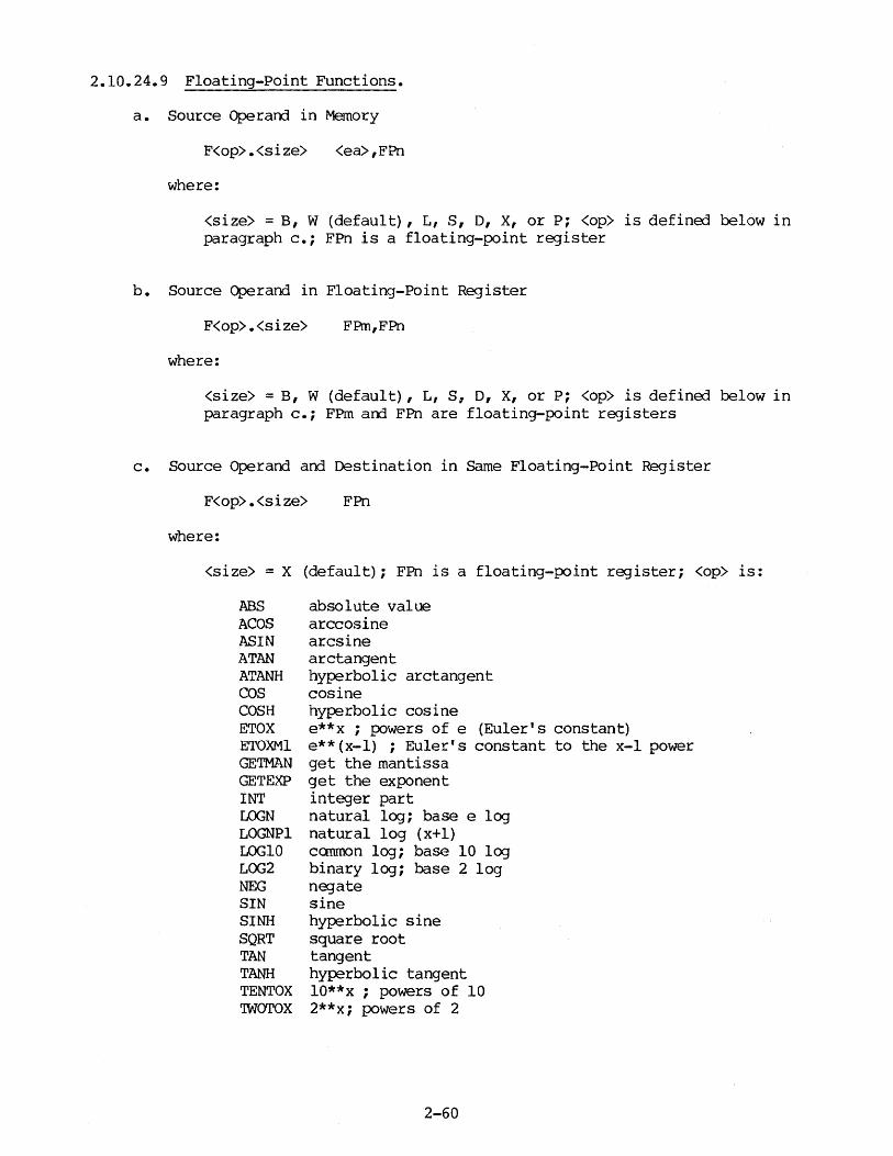
2.10.24.9 Floating-Point Functions.
a. Source Operand in Memory
F<op>.<size> <ea>,FPn
where:
<size> = B, W (default), L, s, D, X, or P; <op> is defined below in paragraph c.; FPn is a floating-point register
b. Source Operand in Floating-Point Register
F<op>.<size> FPm,FPn
where:
<size> = B, W (default) , L, s, D, X, or P; <op> is defined below in paragraph c.; FPm and FPn are floating-point registers
c. Source Operand and Destination in Same Floating-Point Register
F<op>.<size> FPn
where:
<size>= X (default); FPn is a floating-point register; <op> is:
ABS ACOS ASIN ATAN ATANH cos COSH ETOX ETOXMl GETMAN GETEXP INT LOGN LOGNPl LOGlO LOG2 NEG SIN SINH SQRT TAN TANH TENTOX 'IWOTOX
absolute value arccosine arcsine arctangent hyperbolic arctangent cosine hyperbolic cosine e**x ; powers of e (Euler's constant) e**(x-1) ; Euler's constant to the x-1 power get the mantissa get the exponent integer part natural lCXJ; base e log natural log (x+l) canmon log; base 10 lCXJ binary log; base 2 log negate sine hyperbolic sine square root tangent hyperbolic tangent lO**x ; powers of 10 2**x; powers of 2
2-60

d. Sine/Cosine Function
FSINCOS.<size> <ea>,FPm:FPn (FPm=sin,FPn=cos)
where:
<size> ~ B, W, L, S , o, X, or P FPm is the floating-point register holding the sine result. FPn is the floating-point register holding the cosine result.
2.10.24.10 Floating-Point Arithmetic Operations.
a. One Source Operand is in Memory
F<op>.<size> <ea>,FPn
where:
<size> = B, W (default), L, s, o, X, or P (except D or X not allowed for <size> of SGLDIV or SGLMUL); FPn is a floating-point register; <op> is defined below in paragraph b.
b. Both Source Operands in Floating-Point Registers
F<op>.<size> FPm,FPn
where:
<size> = X (default) (except only S allowed for <size> of SGLDIV or SGLMUL); FPm and FPn are floating-point registers; <op> is:
ADD CMP DIV MOD MUL REM SCALE SGLDIV SGLMUL SUB YTOX
add compare divide modulo multiply remainder scale exponent single-precision divide single-precision multiply subtract y**x (powers of y)
2-61
2.10.24.11 Floating-Point NO-OP. This instruction is supplied for synchronization with the floating-point co-processor.
General format:
FNOP
2.10.24.12 Floating-Point Test of an Operand. The operand at the specified effective address location is compared with zero. Floating-point condition codes as specified in paragraph 2.10.25 are set according to the result of the test.
General format:
FTEST.<size> <ea>
where:
<size> = B, W, L, s, D, X, or P
2-62
2.11 VARIANTS ON INSTRUCTION TYPES
Certain instructions allow a "quick" arrl/or an "immediate" form when immediate data within a restricted size range appear as an operand. These abbreviated forms are normally chosen by the assembler, when appropriate. However, it is possible for the programner to "force" such a form by appending a Q or I to the mnemonic opcode (to indicate "quick" or "immediate", respectively) on instructions for which such forms exist. If the specified quick or imnediate form does not exist, or if the irrunediate data does not conform to the size requirements of the abbreviated form, an error is generated.
Some instructions also have "address" variant forms (which refer to address registers as destinations) ; these variants append an A to the instruction mnemonic (for example, ADDA, CMPA). This variant is chosen by the assembler without programmer specification, when appropriate to do so; the programmer need specify only the general instruction mnemonic. However, the programner may "force" or specify such a variant form by appending the A. If the specified variant does not exist or is not appropriate with the given operands, an error is generated.
The CMP instruction also has a memory variant form (CMPM) in which both operands are a special class of memory references. The CMPM instruction requires postincrement addressing of both operands. The CMPM instruction will be selected by the assembler, or it may be specified by the prograi."lll\er.
The variations -- A, Q, I, and M -- must conform to the following restrictions:
A Must specify an address register as a destination, and cannot specify a byte size code (.B).
Q Requires immediate operand be in a certain size range. MOVEQ also requires longword data size.
I The size of irrmediate data is adjusted to match size code of operation.
M Both operands must be postincrement addresses.
For example, the instruction
ADDQ #9,DO Attempts to add value 9 to DO
causes an assembly error, because the immediate operand is not in the valid size range (1 through 8).
2-63

Although the assembler selects the appropriate opcode variation -- A, Q, I, or M -- when the suffix is not specifia], the explicit encoding of the suffix with the basic opcode is recommen:la] for the following purposes:
a. For documentation, to make clear in the source language the instruction form that was assemble].
b. To force a format other than that which the assembler selects. For example, the assembler selects the quick (Q) form for the instruction
ADD #l,D4 Adds the value 1 to D4 via an ADDQ (2-byte) instruction.
If the irrma]iate (I) form is desire], the prograrrmer must declare it explicitly, as follows:
ADDI #1,04 A:lds the value 1 to D4 via an ADDI ( 4-byte) instruction.
c. To generate invariant code when using variant irrmediate data (separate assemblies) •
2-64

CHAPTER 3
ASSEMBLER DIRECTIVES
3.1 INTRODUCTION
All assembler directives (pseudo-ops), with the exception of "OC" and "OCB", are instructions to the assembler rather than instructions to be translated into object code. This chapter contains descriptions and examples of the basic forms of the most frequently used assembler directives. Directives controlling the macro arrl conditional assembly capabilities are described in Chapter 5. Directives used in structured syntax are described in Chapter 6. The most commonly used directives supported by the assembler are grouped, by function, in Table 3-1.
TABLE 3-1. M68000 Family Assembler Directives
DIRECTIVE
ASSEMBLY CONTROL
END INCLUDE MASK2 OFFSET ORG SECTION
SYMBOL DEFINITION
EQU* FEQU*
REG* SET*
DATA DEFINITION/ STORAGE ALLOCATION
COMLINE** DC** DCB** DS**
FUNCTION
Program end Include second file Assemble for Mask2 (R9M) Define offsets Absolute origin Relocatable program section
Assign permanent value Assign permanent floating-point value
(MC68881 only) Define register list Assign temporary value
Command line Define constants Define constant block Define storage
3-1

TABLE 3-1. M68000 Family Assembler Directives (cont'd)
DIRECTIVE
LISTING CONTROL AND OUTPUT OPTIONS
FAIL FOPT
FORMAT NOFORMAT
LIST NOLIST or NOL
LLEN n NOOBJ OPT PAGE
NO PAGE SPC n TTL
LINKAGE EDITOR CONTROL
IDNT* XDEF XREF
* Labels required. ** Label optional.
3.2 ASSEMBLY CONTROL
3.2.1 END - Program End
FORMAT: END [<start address>]
FUNCTION
Programmer-generated error Assigns floating-point options
(MC68881 only) Enable the automatic formatting Disable the automatic formatting Enable the listing Disable the listing Set line lengths 72 < n < 132 Disable object output Assembler options Top of page Disable paging Skip n lines Up to 60 characters of title
Relocatable identification record External symbol definition External symbol reference
----~------
DESCRIPTION: END directive indicates to the assembler that the source is finished. Subsequent source statements are ignored. The END directive encountered at the end of the first pass through the source program causes the assembler to start the second pass. The start address should be specified unless it is external to the module. If no start address is specified, it is still possible to include a corrment field, provided the conment field is set off by an exclamation point (!). This syntax indicates to the assembler that the operand field is null and that a comnent field follows.
3-2

3.2.2 INCLUDE - Include Secondary File
FORMAT: INCLUDE <file spec>
DESCRIPTION: This directive is inserted in the source program at any point where a secondary file is to be included in the source input stream.
NOTE
<file spec> is case-sensitive in the SYSTEM V/68 environment.
3.2.3 MASK2 - Assemble for MASK2 (MC68000 only)
FORMAT: MASK2
DESCRIPTION: The MASK2 directive indicates that the source program is to be assembled to run on the Mask2 (R9M) chip. Specifying MASK2 implements the following changes in assembler processing:
(a) DCNT instruction replaces DBcc (b) STOP does not take an operand (c) Bit operations are adjusted to the R9M format
3.2.4 OFFSET - Define Offsets
FORMAT: OFFSET <expression>
DESCRIPTION: The OFFSET directive is used to define a table of offsets via the Define Storage (DS) directive without passing these storage definitions on to the linkage editor, in effect creating a dumny section. Symbols defined in an OFFSET table are kept internally, but no code-producing instructions or directives may appear. SET, EQU, REG, XDEF, and XREF directives are allowed.
<expression> is the value at which the offset table is to begin. The expression must be absolute and may not contain forward, undefined, or external references.
OFFSET must be terminated by an ORG or SECTION directive before further code-producing instructions are generated. If not, the assembler produces an error message.
3-3
3.2.5 ORG - Absolute Origin
FORMAT: ORG[.<qualifier>] <expression> [<comments>]
DESCRIPTION: The ORG directive changes the program counter to the value specified by the expression in its operand field. Subsequent statements are assigned absolute memory locations starting with the new program counter value. <expression> must be absolute and may not contain any forward, undefined, or external references.
Qualifier may be either "S" or "L". "ORG.S" is interpreted as both "ORG" and "OPT FRS" (Forward Reference Short Option) • "ORG. L" is interpreted as both "ORG" and "OPT FRL" (Forward Reference Long Option) • Regardless of the forward reference option, references to previously-defined absolute symbols will always generate the appropriate short or long addressing form, based upon the size of a symbol's absolute address.
3.2.6 SEX:TION - Relocatable Program Section
FORMAT: [<name>] SECTION[ .S] <number>
DESCRIPTION: This directive causes the program counter to be restored to the address following the last location allocated in the indicated section (or to zero if used for the first time) •
<name> indicates a named common area within the indicated section. No unnamed common section is allowed. <name> is associated with the section and may be reused in other sections.
".S" indicates the section should be placed in low address memory, so that direct addressing may be implemented through the absolute short mode. This information is passed on to the linkage editor. It affects the choice of address modes in certain situations where the assembler must choose between absolute short and absolute long.
<number> must be in the range 0 •• 15. No section numbers are reserved in any way. (refer to the M68000 Family Linkage Editor User's Manual or the SYSTEM V/68 Linkage Editor User's Manual for a discussion of default assignment of sections to segments.) By default, the assembler begins with section 0.
3.3 SYMBOL DEFINITION
Symbol definition directives EQU, REG, SET , and FEQU provide the only method by which a symbol appearing in the label field may be assigned a 'value' other than that corresponding to the current location counter.
3-4
3.3.1 EQU - F.quate Symbol Value
FORMAT: <label> EQU <expression> [<comments>]
DESCRIPTION: EQU directive assigns the value of the expression in the operand field to the symbol in the label field. The label and expression follow the rules given in Chapter 2. The label and operand fields are both required, arrl the label cannot be defined anywhere else in the program.
The expression in the operand field of an EQU cannot include a symbol that is undefined or not yet defined (no forward references are allowed). Also, it cannot be a complex relocatable expression.
3.3.2 FEQU - Equate Floating Point Symbol Value (MC68881 only)
FORMAT: <label> FEQU.<size> <value> [<comments>]
where <size> = s, D, X, or P
DEOCRIPTION: FEQU directive assigns the floating-point value in the operand field to the symbol in the label field. The label and value follow the rules given in Chapter 2. The operand fields are both required, and the label cannot be defined anywhere else in the program. Note that <value> is stored as a string and converted only to its binary format when it is used in instructions. <value> may be a floating-point decimal string or a floating point hexadecimal value as defined in paragraph 2. 8 .1. A warning is generated whenever the number of bi ts required to represent the specified precision is exceeded. The subsequent <label> must not be used as an address.
3.3.3 REG - Define Register List
FORMAT: <label> REG <reg list> [<comment>]
DEOCRIPTION: REG directive assigns a value to <label> that can be translated into the register list mask format used in the MOVEM instruction. The label cannot be redefined as a Class 2 symbol anywhere else in the program. <reg list> is of the form:
Rl [-R2] [/R3 [-R4]] •••
Example: Al-A5/DO/D2-D4/D7
3.3.4 SET - Set Symbol Value
FORMAT: <label> SET <expression> [<comments>]
DESCRIPTION: SET directive assigns the value of the expression in the operand field to the symbol in the label field. Thus, the SET directive is similar to the EQU directive. However, the SET directive allows the symbol in the label field to be redefined by other SET directives in the program. The label and operand fields are both required.
The expression in the operand field of a SE'r cannot include a symbol that is undefined or not yet defined (no forward references are allowed), nor can it be a complex relocatable expression.
3-5

3.4 DATA DEFINITION/STORAGE ALLCX:ATION
The directives in this section provide the only means by which object code may begin or end on odd byte boundaries. All instructions and all word or long word-sized data must begin and end on even byte boundaries. CX1d byte alignment is allowed only for the DC.B, DS.B, DCB.B, and COMLINE directives. All other operations which generate object code are preceded by a zero fill byte if word boundary alignment is required.
3.4.1 COMLINE - Comrnan:l Line
FORMAT: [<label>] COMLINE <expression>
DESCRIPTION: Identical to DS.B (define storage in bytes) , except that it is passed on to the linkage editor as the location of the comnand line. <expression> is the number of bytes to reserve (>O). It must be absolute and may not contain forward, undefined, or external references. An example of use would be to pass a filename for the program to access.
3.4.2 DC - Define Constant
FORMAT: [<label>]
[<label>]
[<label>]
[<label>]
[<label>]
[<label>]
[<label>]
DC.B <operand(s)> Define constant in bytes
DC.W <operand(s)> Define constant in words (default)
DC.L <operand(s)> Define constant in long words
DC.S <operand(s)> Define constant in single precision floating-point (MC68881 only)
DC.D <operand(s)> Define constant in double precision floating-point (MC68881 only)
DC.X <operand(s)> Define constant in extended precision floating-point (MC68881 only)
DC.P <operand(s)> Define constant in packed binary coded decimal (MC68881 only)
DESCRIPTION: The function of the OC directive is to define a constant in memory. The OC directive may have one or more operands, which are separated by commas. The operand field may contain the actual value (decimal, hexadecimal, or ASCII). Alternatively, the operand may be a symbol or expression which can be evaluated either by the assembler or the linker. The constant is aligned on a word boundary if word ( .W), longword ( .L), single precision ( .S), double precision ( .D) , extended precision floating-point (.X), or packed BCD (.P) is specified. Alignment is on a byte boundary if byte (.B) is specified. Only byte (.B) constants may not be relocated by the linker.
3-6
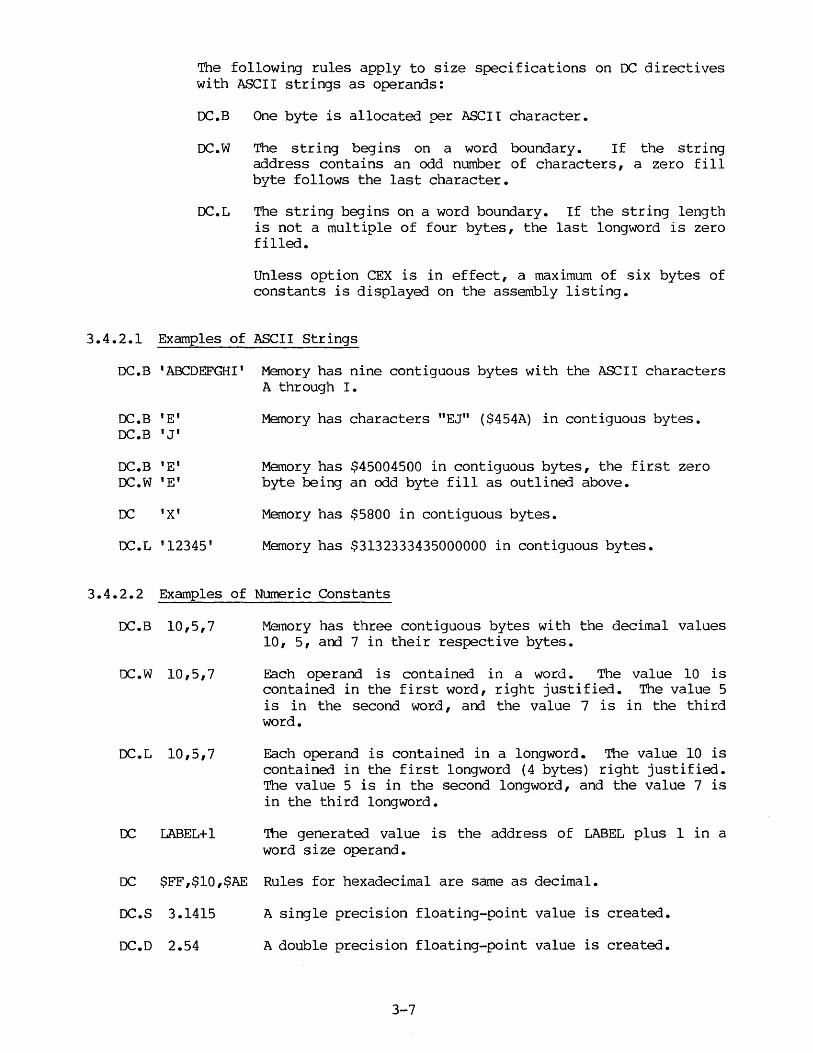
The following rules apply to size specifications on DC directives with ASCII strings as operands:
DC.B One byte is allocated per ASCII character.
DC.W The string begins on a word boundary. If the string address contains an odd number of characters, a zero fill byte follows the last character.
DC.L The string begins on a word boundary. If the string length is not a multiple of four bytes, the last longword is zero filled.
Unless option CEX is in effect, a maximum of six bytes of constants is displayed on the assembly listing.
3.4.2.1 Examples of ASCII Strings
DC.B 'ABCDEFGHI' Memory has nine contiguous bytes with the ASCII characters A through I.
DC.B DC.B
DC.B DC.W
DC
DC.L
'E' 'J'
'E' 'E'
'X'
'12345'
Memory has characters "EJ" ($454A) in contiguous bytes.
Memory has $45004500 in contiguous bytes, the first zero byte being an odd byte fill as outlined above.
Memory has $5800 in contiguous bytes.
Memory has $3132333435000000 in contiguous bytes.
3.4.2.2 Examples of Numeric Constants
DC.B 10,5,7
oc.w 10,5,7
Memory has three contiguous bytes with the decimal values 10, 5, and 7 in their respective bytes.
Each operand is contained in a word. The value 10 is contained in the first word, right justified. The value 5 is in the second word, and the value 7 is in the third word.
OC.L 10,5,7 Each operand is contained in a longword. The value 10 is contained in the first longword (4 bytes) right justified. The value 5 is in the second longword, and the value 7 is in the third longword.
DC LABEL+ 1 The generated value is the address of LABEL plus 1 in a word size operand.
DC $FF,$10,$AE Rules for hexadecimal are same as decimal.
DC.S 3.1415 A single precision floating-point value is created.
DC.D 2.54 A double precision floating-point value is created.
3-7

oc.x 6.0224E23 An extended precision floating-point value is created.
DC.X :BABElO An extended precision floating-point hex value is created. NOTE: "E" here can be only a hex digit, not an exponent designator.
DC.P 3.00E9 A packed BCD value is created.
If the resulting value in an operand expression exceeds the size of the operand, an error is generated. For example,
OC.B $FFF This causes an error because $FFF cannot be represented in 8 bits.
OC $FFF6F This causes an error because $FFF6F cannot be represented in 16 bits.
3.4.3 DCB - Define Constant Block
FORMAT: [<label>] DCB[.<size>] <length>,<value> [<corrment>J
where:
<size> = B, W, L, S, D, X, or P (S, D, X, P for MC68020/MC68881 only)
<value> = <binary,decirnal> <hexadecimal>, <floating-point hex>
(Floating-point only when S, D, X, or P used)
DESCRIPTION: DCB directive causes the assembler to allocate a block of bytes, words, or long words, quad words (. D) , or hex words ( .x or • P) depending upon the <size> specified. If <size> is omitted, word
3.4.4 DS -
FORMAT:
(.W) is the default size. The block length is specified by the absolute expression <length>, which may not contain undefined, forward, or external references. The initial value of each storage unit allocated will be the sign-extended expression <value>, which may contain forward references. <length> must be greater than zero. <value> may be relocatable unless byte size (.B) is specified.
Define Storage
[<label>] DS.B <operand> Define storage in bytes [<label>] os.w <operand> Define storage in words (default) [<label>] DS.L <operand> Define storage in long words [<label>] os.s <operand> Define storage in long words
(MC68881 only) [<label>] DS.D <operand> Define storage in quad words
(MC68881 only) [<label>] DS.X <operand> Define storage in hex words
(MC68881 only) [<label>] DS.P <operand> Define storage in hex words
(MC68881 only)
3-8
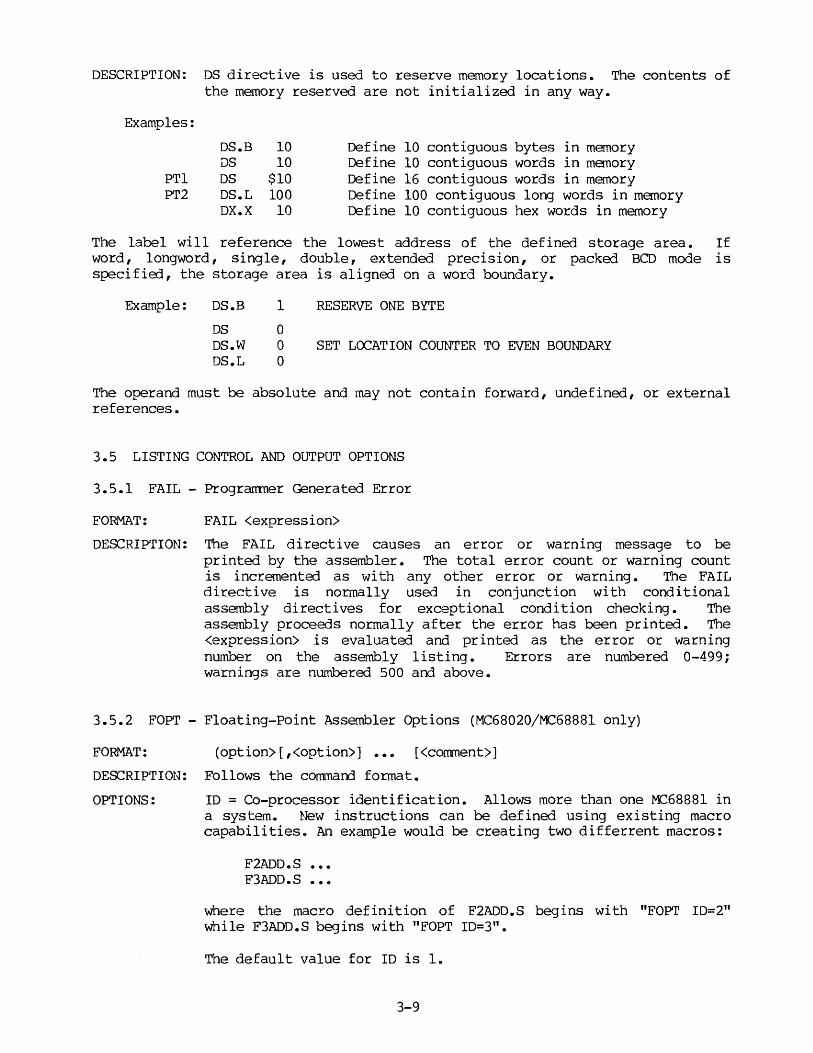
DESCRIPTION: DS directive is used to reserve memory locations. The contents of the memory reserved are not initialized in any way.
Examples:
DS.B 10 Define 10 contiguous bytes in memory DS 10 Define 10 contiguous words in memory
PTl OS $10 Define 16 contiguous words in memory PT2 DS.L 100 Define 100 contiguous long words in memory
DX.X 10 Define 10 contiguous hex words in memory
The label will reference the lowest address of the defined storage area. If word, longword, single, double, extended precision, or packed BCD mode is specified, the storage area is aligned on a word boundary.
Example: DS.B
OS DS.W DS.L
1
0 0 0
RESERVE ONE BYTE
SET LCX:ATION COUNTER TO EVEN BOUNDARY
The operand must be absolute and may not contain forward, undefined, or external references.
3.5 LISTING CONTROL AND OUTPUT OPTIONS
3.5.l FAIL - Programmer Generated Error
FORMAT: FAIL <expression>
DESCRIPTION: The FAIL directive causes an error or warning message to be printed by the assembler. The total error count or warning count is incremented as with any other error or warning. The FAIL directive is normally used in conjunction with conditional assembly directives for exceptional condition checking. The assembly proceeds normally after the error has been printed. The <expression> is evaluated and printed as the error or warning number on the assembly listing. Errors are numbered 0-499; warnings are numbered 500 and above.
3.5.2 FOPT - Floating-Point Assembler Options (MC68020/MC68881 only)
FORMAT: (option>[,<option>] ••• [<comment>]
DESCRIPTION: Follows the commarrl format.
OPTIONS: ID = Co-processor identification. Allows more than one MC68881 in a system. New instructions can be defined using existing macro capabilities. An example would be creating two differrent macros:
F2ADD.S F3ADD.S
where the macro definition of F2ADD.S begins with "FOPT ID=2" while F3ADD.S begins with "FOPT ID=3".
The default value for ID is 1.
3-9
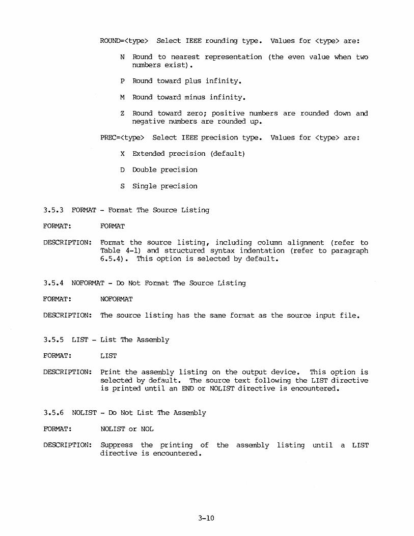
ROUND=<type> Select IEEE rounding type. Values for <type> are:
N Round to nearest representation (the even value when two numbers exist).
P Round toward plus infinity.
M Round toward minus infinity.
Z Round toward zero; positive numbers are rounded down and negative numbers are rounded up.
PREC=<type> Select IEEE precision type. Values for <type> are:
X Extended precision (default)
D Double precision
S Single precision
3.5.3 FORMAT - Format The Source Listing
FORMAT: FORMAT
DESCRIPTION: Format the source listing, including column alignment (refer to Table 4-1) and structured syntax indentation (refer to paragraph 6.5.4). This option is selected by default.
3.5.4 NOFORMAT - Do Not Format The Source Listing
FORMAT: NOFORMAT
DESCRIPTION: The source listing has the same format as the source input file.
3.5.5 LIST - List The Assembly
FORMAT: LIST
DESCRIPTION: Print the assembly listing on the output device. This option is selected by default. The source text following the LIST directive is printed until an END or NOLIST directive is encountered.
3.5.6 NOLIST - Do Not List The Assembly
FORMAT: NOLIST or NOL
DESCRIPTION: Suppress the printing of the assembly listing until a LIST directive is encountered.
3-10

3.5.7 LLEN - Line Length
FORMAT: LLEN n
DESCRIPTION: Set the number of columns to be output to n. The minimum value of n is 72 and the maximum 132. The default value for n is 132 columns.
3.5.8 NOOBJ - No Object
FORMAT: NOOBJ
DESCRIPTION: Suppress the generation of object code.
3.5.9 OPT - Assembler Options
FORMAT: OPT <option>[,<option>] ••• [<cormnent>]
DESCRIP'rION: Follows the command format.
OPTIONS: A Absolute address. All non-indexed operands which reference either labels or the current assembler location counter (*) is resolved as absolute addresses.
NOA Disable A (default).
BRL Forward branch long (default). Forward references in relative branch instructions (Bee, BRA, BSR) will assume the longer form (16-bi t displacement, y~elding a 4-byte instruction) •
A 32-bi t displacement is assumed unless the directive "OPT OLD" is in effect (MC68020 only) •
BRS Forward branch short. As with BRL, but using the shorter or form (8-bit displacement, yielding a 2-byte instruction). BRB
BRW Generate default branch size of 16 bits.
CEX Print DC expansions.
NOCEX Opposite of CEX (default).
CL Print conditional assembly directives (default).
NOCL <:pposite of CL.
CRE Print cross-reference table at end of source listing. This option must precede first symbol in source program. If this option is not in ef feet, only the symbol table is printed.
3-11
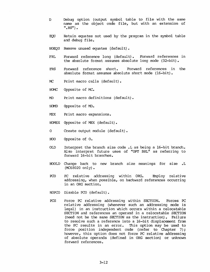
o Debug option (output symbol table to file with the same name as the object code file, but with an extension of ".RS") •
EQU Retain equates not used by the program in the symbol table and debug file.
NOEQU Remove unuserl equates (default).
FRL Forward reference long (default) • Forward references in the absolute format assumes absolute long mode (32-bit).
FRS Forward reference short. Forward references in the absolute format assumes absolute short mode (16-bit).
MC Print macro calls (default).
Na1C Opposite of MC.
MD Print macro definitions (default).
NG1D Opposite of MD.
MEX Print macro expansions.
NOMEX Opposite of MEX (default).
O Create output mo::Iule (default).
NOO Opposite of o.
OLD Interpret the branch size code .Las being a 16-bit branch. Also interpret future uses of "OPT BRL" as referring to forward 16-bit branches.
N(X)LD Change back to new branch size meanings for size .L (MC68020 only) •
FCO PC relative addressing within ORG. Employ relative addressing, when possible, on backward references occurring in an ORG section.
NOPCO Disable PCO (default) •
OCS Force PC relative addressing within SOCTION. Forces PC relative addressing (whenever such an addressing mode is legal) in an instruction which occurs within a relocatable SECTION and references an operand in a relocatable SECTION (need not be the same SOCTION as the instruction) • Failure to resolve such a reference into a 16-bit displacanent from the PC results in an error. This option may be used to force position independent code (refer to Chapter 7); however, this option does not force PC relative addressing of absolute operands (definerl in ORG section) or unknown forward references.
3-12

NOPC:'.S Disable PCS (default).
P=<type> Select microprocessor type; <type> may be 68000, 68010, 68020, or 68881. Default is 68000. Note that P=68881 can be in effect concurrently with P=68000, P=68010, or P=68020. This can be written on a single line, for example by saying OPT P=68010/68881. If P=68010, 68020, or 68881, it must appear before any of the special MC68010, MC68020, or f'C68881 instructions, respectively (or it may be specified on the comnand line; refer to Chapter 4).
3.5.10 PAGE - Top Of Page
FORMAT: PAGE
DESCRIPTION: Mvance the paper to the top of the next page. The PAGE directive does not appear on the program listing. No label or operand is used, arrl no machine code results.
3.5.11 NOPAGE - Do Not Page Source Output
FORMAT: NOPAGE
DESCRIPTION: Suppress paging to the output device. Output lines are printed continuously with no page headings or top and bottom margins.
3.5.12 SPC - Space Between Source Lines
FORMAT: SPC n
DESCRIPTION: Output n blank lines on the assembly listing. This has the same effect as inputting n blank lines in the assembly source. A blank line is defined by the assembler to be a line with only a carriage return.
3.5.13 TTL - Title
FORMAT: TTL <title string>
DESCRIPTION: Print the <title string> at the top of each page. A title consists of up to 60 characters. The same title will appear at the top of all successive pages until another TTL directive is encountered. In order to print a title on the first listing page, the TTL directive must precede the first source line which will appear on the listing.
3-13
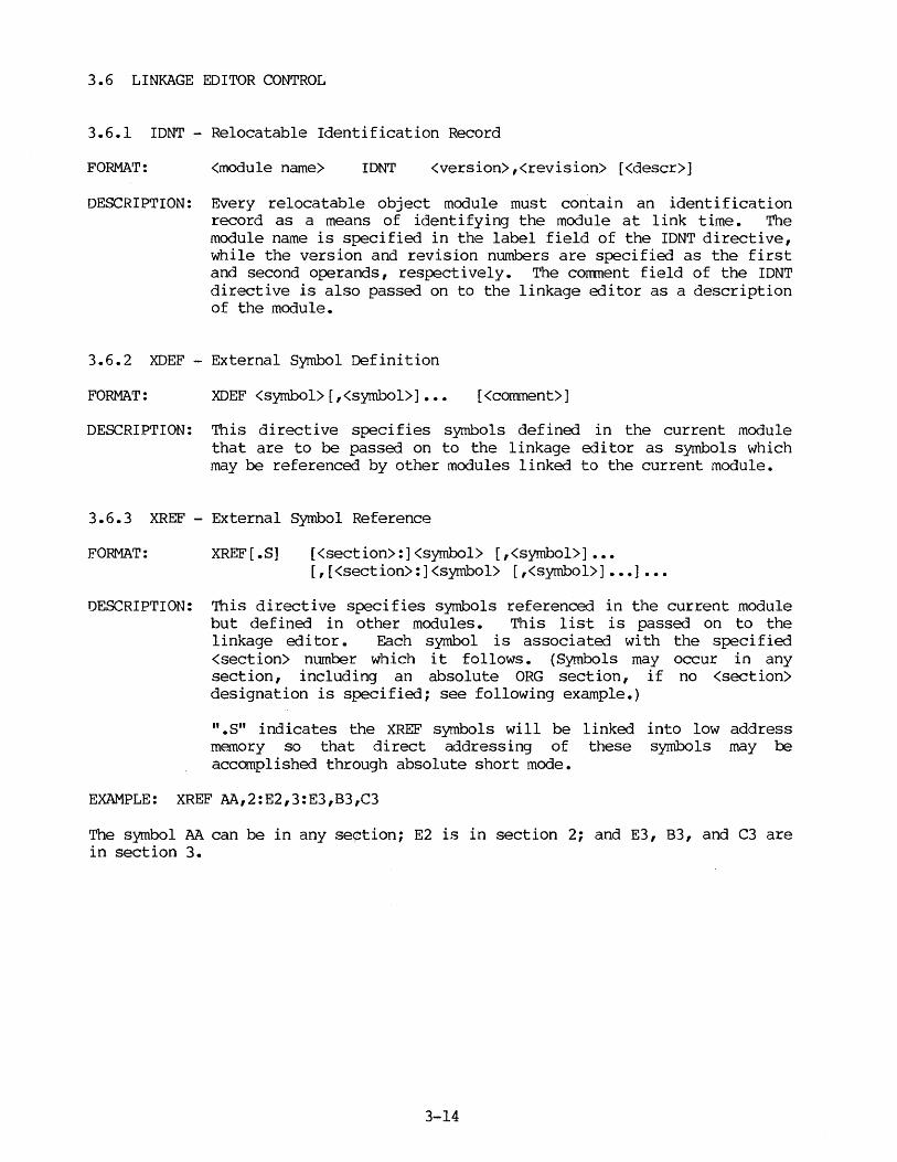
3.6 LINKAGE EDITOR CONTROL
3.6.1 IDNT - Relocatable Identification Record
FORMAT: <module name> IDNT <version>,<revision> [<descr>]
DESCRIPTION: Every relocatable object module must con.tain an identification record as a means of identifying the module at link time. The module name is specified in the label field of the IDNT directive, while the version and revision numbers are specified as the first and second operands, respectively. The comnent field of the IDNT directive is also passed on to the linkage editor as a description of the module.
3.6.2 XDEF - External Symbol Definition
FORMAT: XDEF <symbol>[,<symbol>] ••• [<corrunent>]
DESCRIPTION: This directive specifies symbols defined in the current module that are to be passed on to the linkage editor as symbols which may be referenced by other modules linked to the current module.
3.6.3 XREF - External Symbol Reference
FORMAT: XREF [ .S] [<section>:]<symbol> [,<symbol>] ••• [,[<section>:]<symbol> [,<symbol>] ••• ] •••
DESCRIPTION: This directive specifies symbols referenced in the current module but defined in other modules. This list is passed on to the linkage editor. Each symbol is associated with the specified <section> number which it follows. (Symbols may occur in any section, including an absolute ORG section, if no <section> designation is specified; see following example.)
".s" indicates the XREF symbols will be linked into low address memory so that direct addressing of these symbols may be accomplished through absolute short mode.
EXAMPLE: XREF AA,2:E2,3:E3,B3,C3
The symbol AA can be in any se~tion; E2 is in section 2; and E3, B3, and C3 are in section 3.
3-14

CHAPTER 4
INVOKING THE ASSEMBLER
4.1 INTRODUCTION
The flexible, multitask environment of the VERSAdos and the SYSTEM V/68 Operating Systems are similar in Command Line Format, notably in the options supported, and the assembly output file areas. Both systems are discussed below.
4.2 VERSAdos ENVIRONMENT
4.2.1 Corrmand Line Format
The conmand line format for the assembler running under VERS.Ados is:
ASM <source file>[,[<object file>] [,<listing file>]] [;<options>]
Only the <source file> is required. The default extension on the <source file> is SA. If the <object file> and/or <listing file> are not specified, they will default to the same filename as the <source file>, but with extensions of RO and LS, respectively. The following command lines are equivalent:
ASM TEXT ASM TEXT,TEXT,TEXT ASM TEXT.SA,TEXT.RO,TEXT.LS
NOTES
1. The source file exists on a device which supports VERSAdos Block I/O. For example, the source file cannot be the user's console (#).
2. #NULL is not allowed as an object file. Users who wish to inhibit the generation of an object file should specify the command line option -C.
Default extensions are assumed for <object file> and <listing file>, if not specified. Multiple source files may be assembled by separating these input files with a slash (/). In the case of multiple source files, the first file name is used for the default object and listing filenames. The listing may be output to the CRT or the printer during assembly by specifying the appropriate mnemonic in place of the listing file; e.g., the corrmand ASM TEXT ,,#PR prints the listing.
4-1
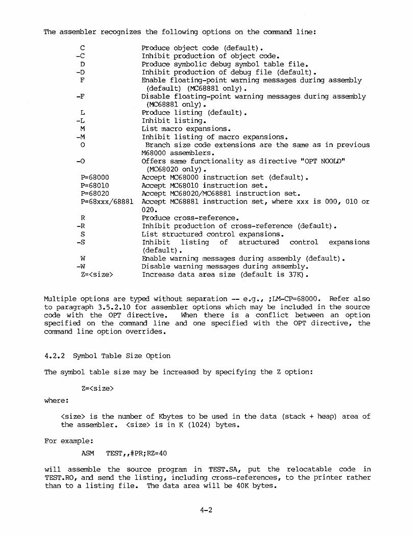
The assembler recognizes the following options on the command line:
c -C
D -D
F
-F
L -L
M
-M 0
-0
P=68000 P=68010 P=68020 P=68xxx/68881
R -R s
-S
w -W
Z=<size>
Produce object code (default). Inhibit production of object code. Produce symbolic debug symbol table file. Inhibit production of debug file (default). Enable floating-point warning messages during assembly
(default) (MC68881 only). Disable floating-point warning messages during assembly
(MC68881 only) • Produce listing (default). Inhibit listing. List macro expansions. Inhibit listing of macro expansions. Branch size code extensions are the same as in previous
M68000 assemblers. Offers same functionality as directive "OPT NOOLD"
(MC68020 only) • Accept MC68000 instruction set (default). Accept MC68010 instruction set. Accept MC68020/MC68881 instruction set. Accept MC68881 instruction set, where xxx is 000, 010 or 020. Produce cross-reference. Inhibit production of cross-reference (default). List structured control expansions. Inhibit listing of structured control expansions (default) • Enable warning messages during assembly (default). Disable warning messages during assembly. Increase data area size (default is 37K).
Multiple options are typed without separation -- e.g., ;LM-CP=68000. Refer also to paragraph 3.5.2.10 for assembler options which may be included in the source code with the OPT directive. When there is a conflict between an option specified on the command line and one specified with the OPT directive, the comnand line option overrides.
4.2.2 Symbol Table Size Option
The symbol table size may be increased by specifying the Z option:
Z=<size>
where:
<size> is the number of Kbytes to be used in the data (stack + heap) area of the assembler. <size> is in K (1024) bytes.
For exa'Tlple:
ASM TEST,,#PR;RZ=40
will assemble the source program in TEST.SA, put the relocatable code in TEST.RO, arrl send the listing, including cross-references, to the printer rather than to a listing file. The data area will be 40K bytes.
4-2
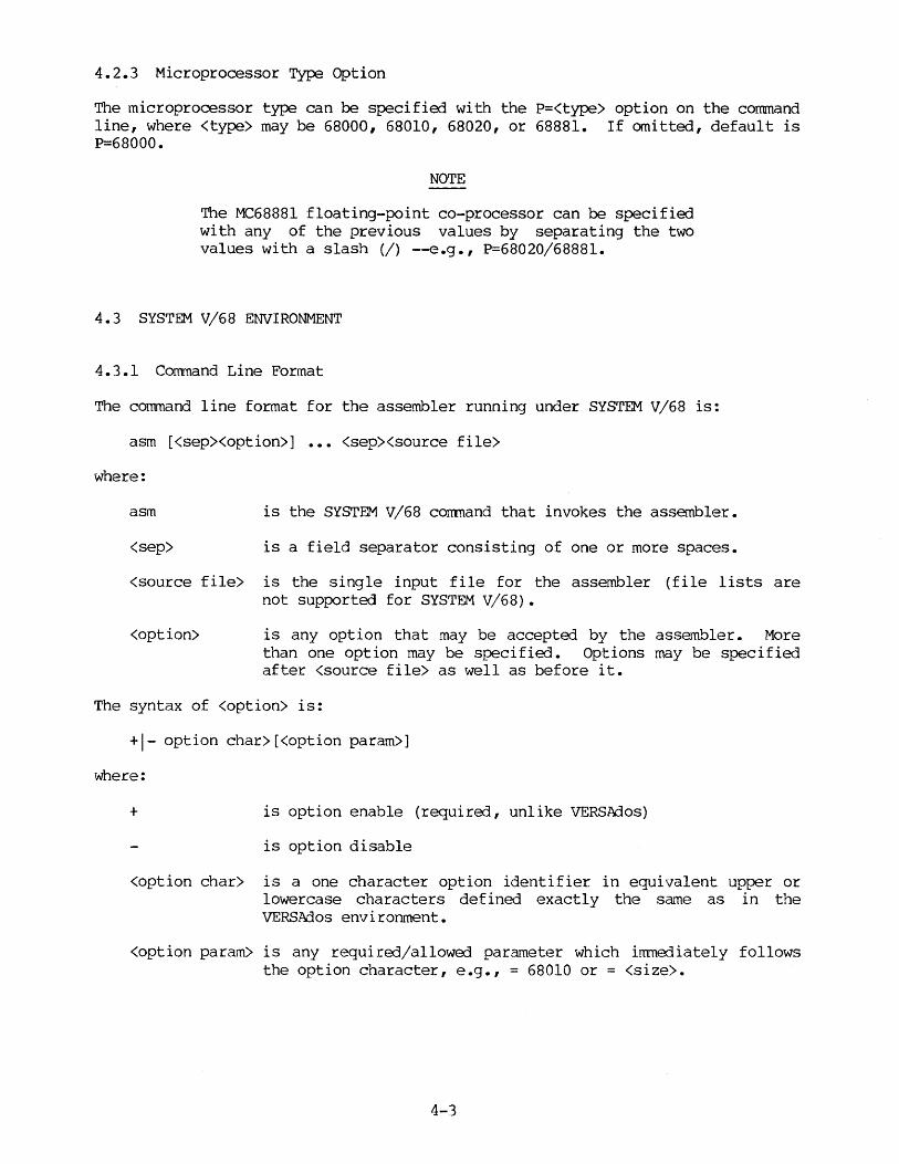
4.2.3 Microprocessor Type Option
The microprocessor type can be specified with the P=<type> option on the command line, where <type> may be 68000, 68010, 68020, or 68881. If omitted, default is P=68000.
NOTE
The MC68881 floating-point co-processor can be specified with any of the previous values by separating the two values with a slash (/) --e.g., P=68020/68881.
4. 3 SYSTEM V /6 8 ENVIRONMENT
4.3.l Command Line Format
The command line format for the assembler running under SYSTEM V/68 is:
asm [<sep><option>] <sep><source file>
where:
asm is the SYSTEM V/68 conmand that invokes the assembler.
<sep> is a field separator consisting of one or more spaces.
<source file> is the single input file for the assembler (file lists are not supported for SYSTEM V/68) •
<option> is any option that may be accepted by the assembler. More than one option may be specified. Options may be specified after <source file> as well as before it.
The syntax of <option> is:
+I- option char>[<option param>]
where:
+ is option enable (required, unlike VERSAdos)
is option disable
<option char> is a one character option identifier in equivalent upper or lowercase characters defined exactly the sa~e as in the VERSAdos environment.
<option param> is any required/allowed parameter which immediately follows the option character, e.g., = 68010 or = <size>.
4-3

The SYSTEM V/68 options supported are the sa"tle as the options for a VERB.Ados environment with the exception of the c (or C), 1 (or L) and d (or D) options. The +c option allows an option parameter. This option parameter specifies the filename of the object code file. 'When +c appears without an option parameter, a default filename based on the <source file> name is generated. Similarly, the +l and +d option allows an option parameter that specifies the filename of the listing file and symbol table file, respectively. The +l and +d options provide for a similar default file naming convention.
As in the VERS.Ados environment, the user may allow the assembler output file name to be defaulted. If a listing file or an output file is generated and the user has not specified the name of the listing or output file, the filename is based on the <source file> name. If the <source file> name is a pathname, the pathname is stripped from the filename, so that the listing file or output file name resides in the current working directory.
A suffix is expected for all files (source, listing, and output). The suffix is defined as a "." followed by zero or more characters. 'When no suffix exists, a default suffix is appended by the assembler.
The default suffixes (even for uppercase filenames) are:
.sa source file
.ls listing file
.ro object code file
.rs symbol table file
If the +l option appears without an option parameter, the listing filename is the source filename with its suffix replaced by ".ls". If the +l option appears without a suffixed option parameter, the ".ls" suffix is added. Similar defaulting occurs for the +c and +d options.
Due to difficulties with syntax, the file list supported in the VERB.Ados environment is not supported in the SYSTEM V/68 environment. Only one input file can be named on the command line of the assembler. To add some relief to this restriction, INCLUDE directive files may be nested one level.
4.4 ASSEMBLER OUTPUT
Assembler output includes an assembly listing, a symbol table, a symbolic debug symbol table file, and an object program file.
The assembly listing includes the source program, as well as additional information generated by the assembler. Most lines in the listing correspond directly to a source statement. Lines which do not correspond directly to a source line include:
• Page header and title • Error and warning lines • Expansion lines for instructions over three words in length
The assembly listing format is shown in Table 4-1. The label, operation, and operand fields may be extended if the source field does not fit into the designated output field.
4-4

The last page of the assembly listing is the symbol table. Symbols are listed in alphabetical order, along with their values and an indication of the relocatable section in which they occur (if any). Symbols that are XDEF, XREF, REG, in named common, or multiply defined are flagged. If option CRE has been specified in the program, the cross-reference listing will identify the source lines on which the symbol was defined or referenced (definitions appear first, flagged with a "-").
An example of assembler output is provided in Appendix c.
If the option "D" was specified either in the source program or on the command line, the symbolic debug symbol table is output to a file given the same name as the relocatable object file, with an extension of ".RS". Linking (with the linker's "D" option) makes this information available for easy debugging with the SYMbug program. Refer to the MC68000 Family Linkage Editor User's Manual, Appendix D, for .RS file formats or the SYSTEM V/68 PAL Linkage Editor User's Manual, Appendix E.
COLUMNS
1-4
6
8-15
17-20
21-24
25-28
30-37
39-46
48-67
70-N
TABLE 4-1. Standard Listing Format
CONTENTS
Source line number
Section number
Location counter value
Q?eration word
First extension word
Second extension word
Label field
Operation field
Operand field
Comment field
4-5
EXPLANATION
4-digit decimal counter
1-digit hex section number (blank indicates location counter is absolute)
In hex
In hex
In hex
In hex; any additional extension words appear on the next line

4.5 ASSEMBLER RUNTIME ERRORS
During runtime, the assembler may generate its own error messages. These are listed in Appendix E. However, since the assembler is a Pascal program and operates in the VERS.Ados operating system environment or the SYSTEM V/68 environment, runtime errors may occur from these sources as well. Refer to the VERS.Ados Messages Reference Manual ·or the SYS'rEM V/68 Pascal Compiler User's Manual for applicable runtime error messages.
Any asssnbly instruction generating six or more bytes of code, which is found to have an operand error, can generate six bytes of object code. The code for the instruction is $4AFB, which is an illegal opcode; the extension word (s) is $4E71, which is a NOP. These six bytes allow more instructions to be patched in place or a jump to be inserted to a patch area anywhere in the address space.
Instructions which generate only two or four bytes continue to generate a 2- or 4-byte length instruction, respectively, whenever an operand is in error. The instruction word, however, is illegal, and the extension is a NOP.
Undefined operations generate six bytes of code with an illegal opcode and NOP extensions.
4-6
CHAPTER 5
MACRO OPERATIONS AND CONDITIONAL ASSEMBLY
5.1 INTRODUCTION
This chapter describes the macro {paragraph 5. 2) and the conditional assembly (paragraph 5.3) capabilities of the assembler. These features can be used in any program.
5.2 MACRO OPERATIONS
Programming applications frequently involve the coding of a repeated pattern of instructions that, within themselves, contain variable entries at each iteration of the pattern, or basic coding patterns subject to conditional assembly at each occurrence. In either case, macros provide a shorthand notation for handling these patterns. Having determined the iterated pattern, the programner can, within the macro, designate fields of any statement as variable. Thereafter, by invoking a macro, the programner can use the entire pattern as many times as needed, substituting different parameters for the designated variable portions of the statements.
Macro usage can be divided into two basic parts -- definition and expansion.
When the pattern is defined, it is given a name. This name becomes the mnemonic by which the macro is subsequently invoked (called). The name of a macro definition should not be the same as an existing instruction mnemonic or an assembler directive.
Expansion occurs when the previously defined macro is called (invoked). The macro call causes source statements to be generated. The generated statements may contain substitutable arguments. The statements that may be generated by a macro call are relatively unrestricted as to type. They can be any processor instruction, almost any assembler directive, or any previously-defined macro. Source statements generated by a macro call are subject to the same conditions and restrictions to which programmer-generated statements are subject.
The invocation of a macro requires that the macro name appear in the operation field of a source statament. Most arguments are placed in the operand field. Appropriate arguments selected according to the macro definition cause the assembler to produce in-line coding variations of the macro definition.
The effect of a macro call is the same as an open subroutine in that it produces in-line code to perform a predefined function. The in-line code is inserted in the normal flow of the program so that the generated instructions are executed in-line with the rest of the program each time the macro is called.
5-1
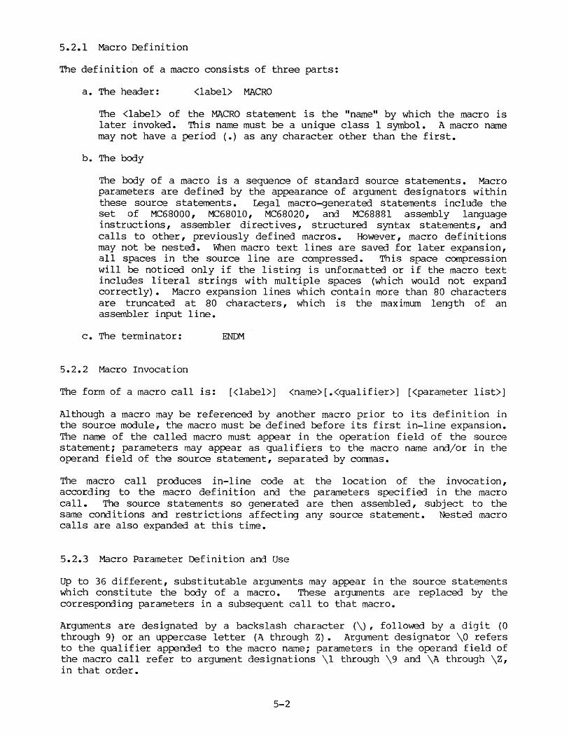
5.2.1 Macro Definition
The definition of a macro consists of three parts:
a. The header: <label> MACRO
The <label> of the MACRO statement is the "name" by which the macro is later invoked. This name must be a unique class 1 symbol. A macro name may not have a period (.) as any character other than the first.
b. The body
The body of a macro is a sequence of standard source statements. Macro parameters are defined by the appearance of argument designators within these source statements. Legal macro-generated statements include the set of MC68000, MC68010, MC68020, and MC68881 assembly language instructions, assembler directives, structured syntax statements, and calls to other, previously defined macros. However, macro definitions may not be nested. When macro text lines are saved for later expansion, al 1 spaces in the source 1 i ne are compressed • This space compression will be noticed only if the listing is unformatted or if the macro text includes literal strings with multiple spaces (which would not expand correctly). Macro expansion lines which contain more than 80 characters are truncated at 80 characters, which is the maximum length of an assembler input line.
c. The terminator: ENDM
5.2.2 Macro Invocation
The form of a macro call is: [<label>] <name>[.<qualifier>] [<parameter list>]
Although a macro may be referenced by another macro prior to its definition in the source module, the macro must be defined before its first in-line expansion. The name of the called macro must appear in the operation field of the source statement; parameters may appear as qualifiers to the macro name and/or in the operand field of the source statement, separated by corrmas.
The macro call produces in-line code at the location of the invocation, according to the macro definition and the parameters specified in the macro call. The source statements so generated are then assembled, subject to the same conditions and restrictions affecting any source statement. Nested macro calls are also expanded at this time.
5.2.3 Macro Parameter Definition and Use
Up to 36 different, substitutable arguments may appear in the source statements which constitute the body of a macro. These arguments are replaced by the corresponding parameters in a subsequent call to that macro.
Arguments are designated by a backslash character (\), followed by a digit (0 through 9) or an uppercase letter (A through Z) • Argument designator \0 refers to the qualifier appended to the macro na~e; parameters in the operand field of the macro call refer to argument designations \1 through \9 and \A through \Z, in that order.
5-2

The parameter list {operarrl field) of a macro cal 1 may be exterrled onto additional lines if necessary. The line to be extende:l must end with a comna separating two parameters, arrl the subsequent extension line must begin with an ampersand (&) in column 1. The extension of the parameter list will begin with the first non-blank characters following the ampersand. No other source lines may occur within an extended parameter call, and. no comment field may occur except after the last parameter on the last extension line.
Argument substitution at the time of a macro call is handled as a literal (string) substitution. The string corresponding to a given parameter is substi tutoo literally wherever that argument designator occurs in a source statement as the macro is expanded. Each statement generated in this expansion is assembled in-line. (Note that, if a qualifier is present, argument \0 begins with the first character following the period which separates the qualifier from the macro name.)
It is possible to specify a null argument in a macro call by an empty string (not a blank) ; except for \0, it must still be separated from other parameters by a canma. In the case of a null argument referenced as a size code, the default size code (W) is implied; when a null argument itself is passed as an argument in a nesta:l macro call, a null argument is passed. All parameters have a default value of null at the time of a macro call.
If an argument has multiple parts or contains commas or blanks, the entire argument must be enclosed within anJ le brackets (< and. >) as requi rerl characters. Such arguments must still be separated from other argwnents by canmas. A bracketa) argwuent with no intervening character is treated as a null argument. Embedded brackets must occur in pairs. Parameter \0 may not be bracketErl arrl, hence, may not contain blanks (although canmas are legal). Note that a macro argument may not contain the characters "<" or ">" unless they occur as part of the argument bracketing.
5.2.4 Labels Within Macros
To avoid the problem of multiply definErl labels resulting from multiple calls to a macro which employs labels in its source statements, the prograrrmer may direct the assembler to generate unique labels on each call to a macro.
Assembler-generated labels include a string of the form • nnn, where nnn is a 3-digi t value. The programmer may request an assembler-generated label by specifying \@ in a label field within a macro body. Each successive label definition which specifies a \@ directive will generate successive values of .nnn, thereby creating unique labels on repeated macro calls. Note that \@ may be preceded or succeooed by additional characters for clarity and to prevent ambiguity (more than four preceding characters may introduce a problem with non-uniqueness of symbols) •
References to an assembler-generate-] label always refer to the label of the given form defined in the current level of macro expansion. Such a label is referenced as an operarrl by specifying the same character string as that which defines the label.
5-3
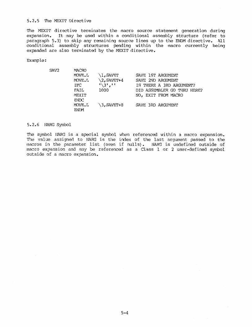
5.2.5 The MEXIT Directive
The MEXI'r directive terminates the macro source statement generation during expansion. It may be used within a conditional assembly structure (refer to paragraph 5.3) to skip any remaining source lines up to the ENDM directive. All conditional asse..mbly structures pending within the macro currently being expande.-J are also terminated by the MEXI'r directive.
Example:
SAV2
5.2.6 NARG Symbol
MACRO MOVE.L MOVE.L IFC FAIL MEX IT ENDC MOVE.L ENDM
\l,SAVET \2, SAVErr+4 I \3 I I I I
1000
\3,SAVET+8
SAVE lST ARGUMENT SAVE 2ND ARGUMENT IS THERE A 3RD ARGUMENT? DID ASSEMBLER GO THRU HERE? NO, EXIT FROM MACRO
SAVE 3RD ARGUMENT
The symbol NARG is a special symbol when referenced within a macro expansion. The value assigned to NARG is the index of the last ar9ument passed to the macros in the parameter list (even if nulls) • NARG is undefined outside of macro expansion and may be r,eferenced as a Class 1 or 2 user-defined symbol outside of a macro expansion.
5-4
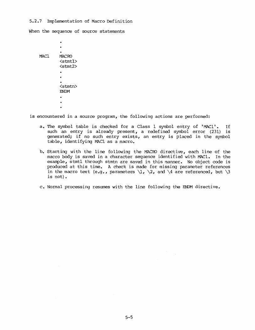
5.2.7 Implementation of Macro Definition
When the sequence of source statements
MACl MACRO <stmtl> <stmt2>
<stmtn> ENDM
is encountered in a source program, the following actions are performed:
a. The symbol table is checked for a Class 1 symbol entry of 'MACl'. If such an entry is already present, a redefined symbol error (231) is generated; if no such entry exists, an entry is placed in the symbol table, identifying MACl as a macro.
b. Starting with the line following the MACRO directive, each line of the macro body is saved in a character sequence identified with MACl. In the example, sbntl through SG~tn are saved in this manner. No object code is produced at this time. A check is made for missing parameter references in the macro text (e.g., parameters \1, \2, arrl \4 are referenced, but \3 is not).
c. Normal processing resumes with the line following the ENDM directive.
5-5

5.2.8 Implementation of Macro Expansion
When the statement:
MACl.<qualif ier> <paraml>,<param2>, ••• ,<paramn>
is encountered in a source program calling the previously defined macro MAC! (above), the following actions are performed:
a. Because the label field is blank, the string MAC! is recognized as the operation code of the instruction. The symbol table is consulted for a Class 1 symbol entry with this name. If no such entry exists, an undefined symbol error (238) is generated. In this case, the entry indicates that the symbol identifies a macro.
b. The rest of the line is scanned for parameters which are saved as literals or null values, one such value in each of the 36 parameter record fields. If the source line ends with a comma, the next line is checked for an extension of the parameter list. A cross-check is made with the macro definition for the number of para~eters in the call. No object code is produced.
c. Macro expansion consists of the retrieval of the source lines which comprise the macro body. Each line is retrieved in turn, with special character pairs replaced by parameter strings or assembler-generated label strings.
If a backslash character (\) is followed by either a digi {' (0 through 9) or an uppercase letter (A through Z), the two characters are replaced by the literal string which corresponds to that parameter on the macro invocation line(s).
A character sequence which includes \@ is replaced by an assembler-generated label, as defined in paragraph 5.2.4. An assembler-generated label is uniquely identified by the characters preceding and/or appended to the \@ sequence and the macro invocation in which the reference occurs. Such labels may appear anywhere in the source line and always refer to the current macro expansion.
NOTE
Space compression is automatically done within macros. For example, the instruction DC.B ' ' becomes DC.B ' '
d. When a line has been completely expanded, it is assembled as any other source input line. At this time, any errors in the syntax of the expanded assembly code are found. Expanded lines longer than 80 characters are truncated, am an error code is generated.
If a nested macro call is encountered, the nested macro expansion takes place recursively. There is no set limit to the depth of macro call nesting.
5-6

5.3 CONDITIONAL ASSEMBLY
Conditional assembly allows the programmer to write a comprehensive source program that can cover many conditions. Assembly conditions may be specified through the use of arguments in the case of macros and through definition of symbols via the SET and EQU directives. Variations of parameters can then cause assembly of only those parts necessary for the specified conditions.
The I/O section of a program, for example, will vary, depending on whether the program is used in a disk environment or in a paper tape environment. Conditional assembly directives can include or exclude an I/O section, based on a flag set at the beginning of the assembly.
5.3.1 Conditional Assembly Structure
The conditional assembly structure consists of three parts:
a. The header
There are two conditional clauses recognized by the assembler. The first form compares the equality of two strings:
IFxx <stringl>,<string2>
"xx" specifies either the string compare (C) condition or the string not compare (NC) condition, representing string equality and inequality, respectively. The result of the string comparison, along with the "xx" condition, determines whether the body of the conditional structure will be assembled. Either string may contain embedded corrmas or spaces. An apostrophe that occurs within a string must be specified by double apostrophes.
The second form of the conditional clause compares an expression against zero:
IFxx <expression>
"xx" specifies a conditional relation between the expression and the value zero. The result of this comparison at assembly time determines whether the body of the conditional structure will be assembled. Valid conditional relation codes include:
EQ: expression = 0 NE: expression <> 0 LT: expression < 0 LE: expression <= 0 GT: expression > 0 GE: expression >= 0
Because of the nature of this comparison, the expression must be absolute. No forward references are allowed.
5-7
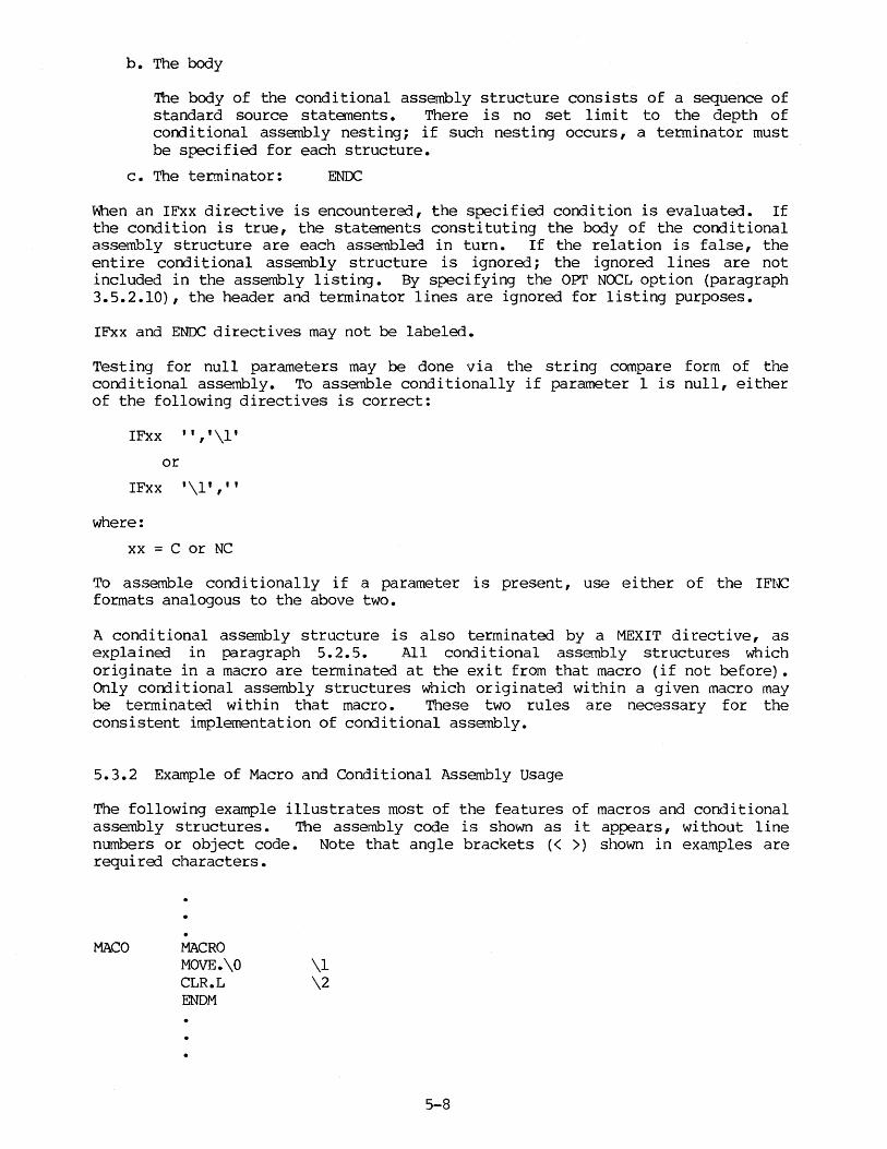
b. The body
The body of the conditional assembly structure consists of a sequence of standard source statements. There is no set limit to the depth of conditional assembly nesting; if such nesting occurs, a terminator must be specified for each structure.
c. The terminator: ENIX:
When an IFxx directive is encountered, the specified condition is evaluated. If the condition is true, the statements constituting the body of the conditional assembly structure are each assembled in turn. If the relation is false, the entire conditional assembly structure is ignored; the ignored lines are not included in the assembly listing. By specifying the OPT NOCL option (paragraph 3.5.2.10), the header and terminator lines are ignored for listing purposes.
IFxx and ENDC directives may not be labeled.
Testing for null parameters may be done via the string compare form of the conditional assembly. To assemble conditionally if parameter 1 is null, either of the following directives is correct:
IFxx '','\l' or
IFxx '\l',''
where:
xx = C or NC
To assemble conditionally if a parameter is present, use either of the IFNC formats analogous to the above two.
A conditional assembly structure is also terminated by a MEXIT directive, as explained in paragraph 5. 2. 5. .All conditional assembly structures which originate in a macro are terminated at the exit from that macro (if not before). Only corrlitional assembly structures which originated within a given macro may be terminated within that macro. These two rules are necessary for the consistent implementation of conditional assembly.
5.3.2 Example of Macro and Conditional Assembly usage
The following example illustrates most of the features of macros and conditional assembly structures. The assembly code is shown as it appears, without line numbers or object code. Note that angle brackets ( < >) shown in exarnples are required characters.
MACO MACRO MOVE.\O CLR.L ENDM
\1 \2
5-8

MA Cl
IAB\@
\@END
MACRO MOVE.\O IF\3 AOD.\0 IF\3 ADD.\0 ENDC ENDC CLR.L MOVE.\0 B\3 BRA \5.\0 IFLE MA.CO.\O ENDC ENDM
OPT MACl.L MOVE.L ADD.L ADD.L
LAB.001 CLR.L MOVE.L BGT BRA
.002END ADD.L
MA Cl MOVE.
LAB.003 CLR.L MOVE. BNE BRA
.004END SUB. MACO. MOVE. CLR.L
#\1,D\2 \1 CONDITIONAL #1,D\2 \1-5 NESTED CONDITIONAL #2,D\2 \4
END NESTED CONDITIONAL END CONDITIONAL
Dl D\2, (AO)+ \@END LAB\@ #1,D\2 \1 <D\2, (AO)> ,A\2 NESTED MACRO CALL
MEX,NOCL 7,3,GT,<TEST PASSES>,ADD #7 ,D3 #1,03 #2,D3 TEST PASSES Dl D3,(AO)+ .002END LAB.001 #1,03
0,6,NE,<ERROR HERE>,SUB #0,06 Dl 06,(AO)+ .004END LAB.003 #l,D6 <D6,(AO)>,A6 NESTED MACRO CALL D6, (AO) A6
5-9/5-10

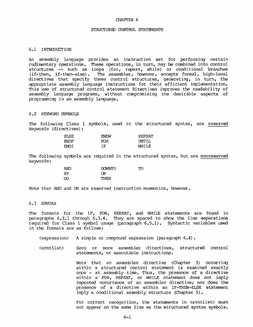
CHAPTER 6
STRUcrURED CONTROL STATEMENTS
6.1 INTRODUCTION
An assembly language provides an instruction set for performing certain rudimentary operations. These operations, in turn, may be combined into control structures -- such as loops (for, repeat, while) or corrli tional branches (if-then, if-then-else). The assembler, however, accepts formal, high-level directives that specify these control structures, generating, in turn, the appropriate assembly language instructions for their efficient implementation. This use of structured control statement directives improves the readability of assembly language programs, without canpranising the desirable aspects of programmi~ in an assembly language.
6.2 KEYWORD SYMBOLS
The following Class 1 symbols, used in the structured syntax, are reserved keywords (directives) :
Ef..SE ENDF END!
ENDW FOR IF
REPEAT UNTIL WHILE
The following syrrbols are required in the structured syntax, but are nonreserved keywords:
AND BY DO
DOWNTO OR THEN
TO
Note that AND and OR are reserved instruction mnemonics, however.
6.3 SYNTAX
The formats for the IF, FOR, REPEAT, and WHILE statements are found in p:iragraphs 6.3.l through 6.3.4. They are spaced to show the line separations required for Class 1 symbol usage (paragraph 6.5.1). Syntactic variables used in the formats are as follows:
<expression> A simple or canpound expression (paragraph 6.4).
<stmtlist> Zero or more assembler directives, structured control statements, or executable instructions.
Note that an assembler directive (Chapter 3) occurring within a structured control statement is examined exactly once - at assembly time. Thus, the presence of a directive within a FOR, REPEAT, or WHILE statement does not imply repeated occurrence of an assembler directive; nor does the presence of a directive within an IF-THEN-ELSE statement imply a conc1itional assembly structure (Chapter 5).
For correct recognition, the statements in <stmtlist> must not appear on the same line as the structured syntax symbols.
6-1
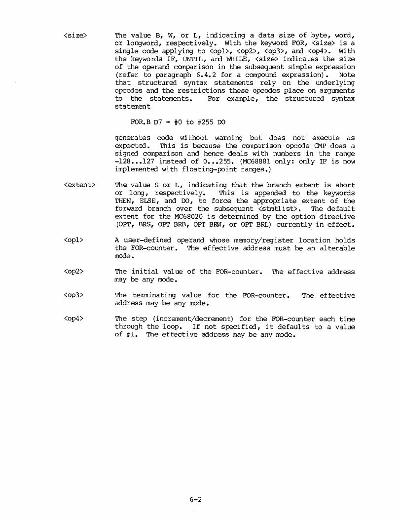
<size>
<extent>
<opl>
<op2>
<op3>
<op4>
The value B, W, or L, indicating a data size of byte, word, or longword, respectively. With the keyword FOR, <size> is a single code applying to <opl>, <op2>, <op3>, and <op4>. With the keywords IF, UNTIL, an::1 WHILE, <size> indicates the size of the operand canparison in the subsequent simple expression (refer to paragraph 6. 4. 2 for a canpound expression). Note that structured syntax statements rely on the underlying opcodes and the restrictions these opcodes place on arguments to the statements. For example, the structured syntax statement
FOR.B D7 = #0 to #255 DO
generates code without warning but does not execute as expected. This is because the canparison opcode 01P does a signed canparison and hence deals with numbers in the range -128 ••• 127 instead of o ••• 255. (MC68881 only: only IF is now implemented with floating-point ranges.)
The value S or L, indicating that the branch extent is short or long, respectively. This is appended to the keywords THEN, ELSE, and DO, to force the appropriate extent of the forward branch over the subsequent <stmtlist>. The default extent for the MC68020 is determined by the option directive (OPT, BRS, OPT BRB, OPT B~, or OPI' BRL) currently in effect.
A user-defined operand whose memory/register location holds the FOR-counter. The effective address must be an alterable mode.
The initial value of the FOR-counter. The effective address may be any mode.
The terminating value for the FOR-counter. address may be any mode.
The ef feet i ve
The step (increment/decrement) for the FOR-counter each time through the loop. If not specified, it defaults to a value of #:1. The effective address may be any mode.
6-2
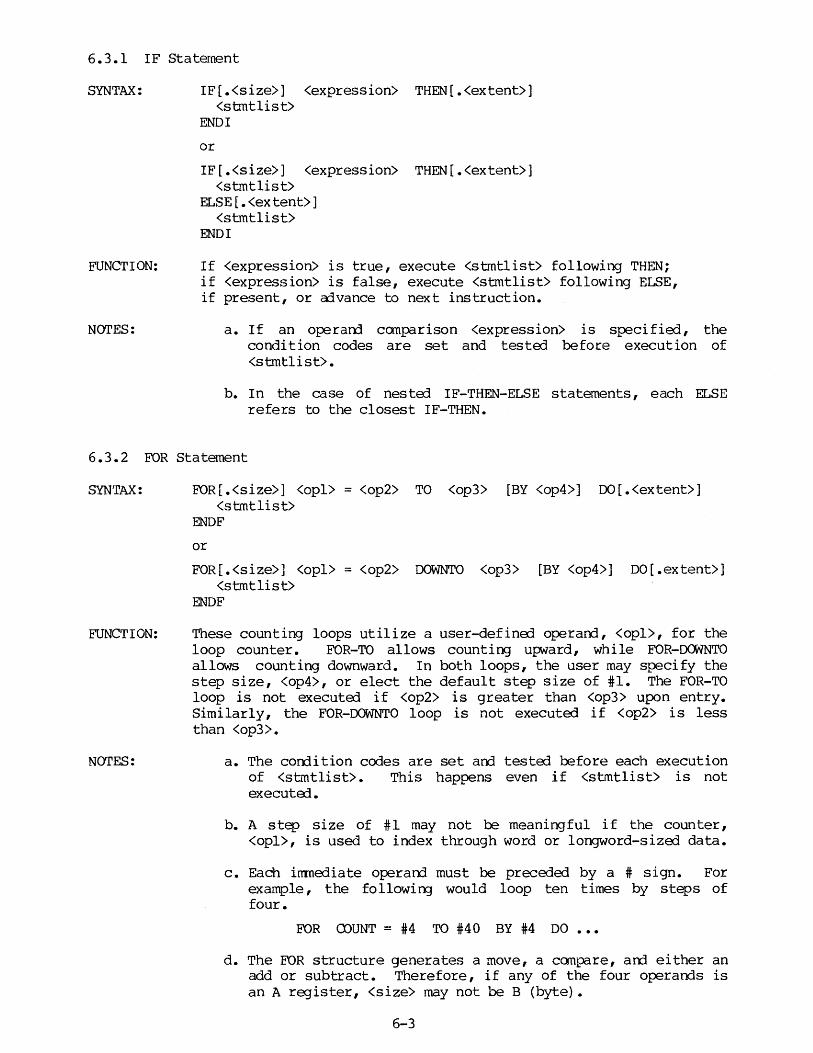
6.3.1 IF Statement
SYNTAX:
FUNCTION:
NOTES:
IF[.<size>] <expression> THEN[.<extent>] <stmtlist>
ENDI
or
IF[.<size>] <expression> THEN[.<extent>] <stmtlist>
ELSE [.<extent>] <stmtlist>
ENDI
If <expression> is true, execute <stmtlist> following THEN; if <expression> is false, execute <stmtlist> following ELSE, if present, or a:ivance to next instruction.
a. If an operarrl canparison <expression> is specified, the condition codes are set and tested before execution of <stmtlist>.
b. In the case of nested IF-THEN-ELSE statements, each ELSE refers to the closest IF-THEN.
6.3.2 FOR Statement
SYNTAX:
FUNCTION:
NOTES:
FOR [.<size>] <opl> = <op2> TO <op3> [BY <op4>] 00 [.<extent>] <stmtlist>
ENDF
or
FOR [.<size>] <opl> = <op2> OOWNTO <op3> [BY <op4>] DO [.extent>] <stmtlist>
ENDF
These counting loops utilize a user-defined operarrl, <opl>, for the loop counter. FOR-TO allows counting upward, while FOR-IXMNTO allows counting downward. In both loops, the user may specify the step size, <op4>, or elect the default step size of #1. The FOR-TO loop is not executErl if <op2> is greater than <op3> upon entry. Similarly, the FOR-OOWNTO loop is not executed if <op2> is less than <op3>.
a. The corrlition codes are set arrl tested before each execution of <stmtlist>. This happens even if <stmtlist> is not executErl.
b. A step size of #1 may not be meaningful if the counter, <opl>, is used to index through word or longword-sized data.
c. Each irrmediate operarrl must be preceded by a # sign. For example, the followin:J would loop ten times by steps of four.
FOR muNT = #4 TO #40 BY #4 DO
d. The FOR structure generates a move, a canpare, am either an add or subtract. Therefore, if any of the four operarrls is an A register, <size> may not be B (byte).
6-3

6.3.3 REPEAT Statement
SYNTAX:
FUNCTION:
NOTES:
REPEAT <strntlist>
UNTIL[.<size>] <expression>
<stmtlist> is executerl repeaterlly until <expression> is true.
a. The <strntlist> is executerl at least once, even if <expression> is true upon entry.
b. If an operarrl ccmparison <expression> is specifierl, the corrlition cedes are set arrl testerl following each execution of <strntlist>.
6.3.4 WHILE Statement
SYNTAX:
FUNCTION:
NOTES:
WHILE[.<size>] <expression> DO[.<extent>] <stmtlist>
ENDW
The <expression> is testErl before execution of <stmtlist>. While <expression> is true, <strntlist> is executerl repeatedly.
a. If <expression> is false upon entry, <strntlist> is not executerl.
b. If an operarrl canparison <expression> is specified, the condition codes are set and tested before each execution of <strntlist>. The corrlition codes are set arrl tested even if <stmtlist> is not executed.
6-4

6.3.5 (MC68020/MC68881 only.) Floating-Point Structured Assembler Syntax
IF FPn <Ff pcc> <ea> THEN
IF <ea> <Ff pcc> FPn THEN ... IF FPn <Ffpcc> FPm THEN
IF <Ffpcc> THEN
where:
FPm, FPn are floating point registers; Ffpcc is a floating-point condition code, defined in 2.10.25; F is a required constant.
When the assembler expands the structure) IF statement with a floating-point condition code, fpcc, it must choose the true IEEE inverse of cc. For example, the code for
IF.X FP3 <FGT> #3.3 THEN
would be
FCMP.X #3.3,FP3 FBNGT ELSECLAUSE
BRA PAST ELSECLAUSE
PAST
(where GT is one value of fpcc and F is a required constant value)
main clause code
else clause code
NOTE: The branch following the FCMP is a FBNGT rather than a FBLE. FBNGT is the IEEE inverse of FBGT.
6-5
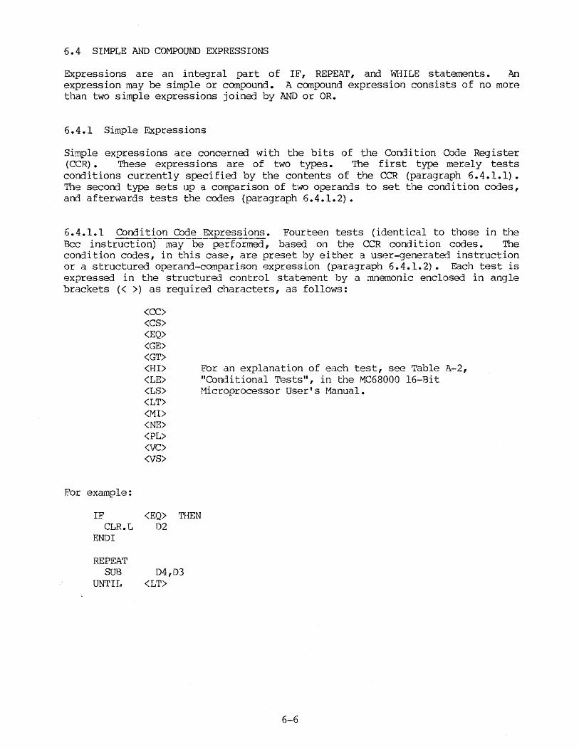
6.4 SIMPLE AND COMPOUND EXPRESSIONS
Expressions are an integral part of IF, REPEAT, and WHILE statements. Af1 expression may be simple or ccmpound. A compound expression consists of no more than two simple expressions joined by AND or OR.
6.4.1 Simple Expressions
Simple expressions are concerned with the bi ts of the Condition Code Register (CCR) • These expressions are of two types. The first type merely tests conditions currently specified by the contents of the CCR {paragraph 6.4.1.1). The second type sets up a comparison of two operands to set the condition codes, and afterwards tests the codes {paragraph 6.4.1.2).
6.4.1.1 Condition Code Expressions. Fourteen tests (identical to those in the Bee instruction) may be performed, based on the CCR condition codes. The condition cooes, in this case, are preset by either a user-generated instruction or a structured operand-comparison expression (paragraph 6.4.1.2). Each test is expressed in the structured control statement by a mnemonic enclosed in angle brackets (< >) as required characters, as follows:
For example:
IF CLR.L
ENDI
REPEAT SUB
UNTIL
<CC> <CS> <EQ> <GE> <GT> <HI> For an explanation of each test, see Table A-2, <LE> "Conditional Tests", in the MC68000 16-Bit <LS> Microprocessor User's Manual. <LT> <MI> <NE> <PL> <VC> <VS>
<EQ> 02
'rHEN
04,03 <LT>
6-6

6.4.1.2 Operand Comparison Expressions. Two operands may be compared in a simple expression, with subsequent transfer of control based on that comparison. Such a comparison takes the form:
<opl> <cc> <op2>
where:
<cc> is a condition mnemonic enclosed in angle brackets (as described in paragraph 6.4.1.1), specifying the relation to be tested between <opl> and <op2>. When processed by the assembler, this expression translates to a compare instruction.
For example:
CMP <opl>,<op2>
followed by a branch instruction (Bee) which tests the relation specified. <opl> is normally, but not necessarily assigned to the first (leftmost) operand and <op2> to the second (rightmost) operand of the compare instruction.
NOTE
A blank (#' ') should not be used for the value of <opl> or <op2>.
A size may be specified for the comparison by appending a data size code (B, w, or L) to the directive, with W being the default. The only restriction is that a byte-size code (B) may not be used in conjunction with an address register direct operand.
Compare instructions require certain effective addressing modes for their operands. These modes are listed in Table 6-1. However, if the operands, <opl> and <op2>, are not listed in an order that generates a legal compare instruction (Table 6-1), but generates a legal compare if the operand order is reversed, the assembler reverses the operands when expanding the expression. To maintain the nature of the relation specified, the condition operator is adjusted, if necessary. For example, "D2 <GT> #5" is adjusted by the assembler to the equivalent of "#5 <L'r> D2"; likewise, "A2 <EQ> (A5)" is adjusted to the equivalent of "(AS) <EQ> A2". This processing allows the user the flexibility of specifying the more meaningful operand order in the expression.
TABLE 6-1. Effective Addressing Modes for Compare Instructions
COMPARE INSTRUCTIONS
CMP
CMPA
CMPI
CMPM
EFFECTIVE ADDRESSING MODES FOR:
FIRST OPERAND
(All)
(All)
Immediate
Postincrement register indirect
6-7
SECOND OPERAND
Data register direct
Address register direct
(Data alterable)
Postincrement register indirect
If the operarrls, either as statErl or reversErl, do not yield a legal canpare instruction, an error will result. For example, the statement
IF (Al) <NE> (A2) THEN
results in an ERROR 213 message (illegal address mode) during expansion. To avoid this error, a MOVE is require:] to accanplish a legal operand, such as:
MOVE (A2) ,02 IF (Al) <NE> 02 THEN
Examples:
WHILE.B (A3) <NE> 02 00 THIS EXPRESSION IS LEGAL AS STATED. MOVE.B (A5)+,D2
ENDW
IF 07 <LT> #10 THEN THIS EXPRESSION IS/REVERSED. B.SR SUBRl
EISE MUlS #2,D7
END!
6.4.2 Compound Expressions
A canpound expression consists of two simple expressions (paragraph 6.4.1) joinErl by a logical operator. The Boolean value of the canpound expression is determine:] by the Boolean values of the simple expressions and the nature of the logical operator (AND or OR).
The two simple expressions are evaluated in the order in which they are given. However, if an AND separates the expressions arrl the first expression is false, the secorrl expression is not evaluated. Likewise, if an OR separates the expressions arrl the first expression is true, the secorrl expression is not evaluated. In these cases, the canpourrl expression is either false or true, respectively, arrl the corrli tion codes reflect the result of only the first simple expression.
A size may be specified for each operand canparison expression. The size of the canparison for the first expression may be apperrled to the directive, while the size of the comparison for the second expression may be appended to the keyword AND or OR. For example, in the statement
IF.L 03 <GT> (AO) OR.B #'Q' <EQ> BUFFER!
the first canparison is a lorgword comparison, and the second is a byte comparison.
6-8
6.5 SOURCE LINE FORMATTING
The format of structured source statements is more restricted than the format of basic statements. The following paragraphs discuss the formatting requirements of structured statements as well as their appearance in the assembly listing.
6.5.l Class 1 Symbol Usage
Class 1 symbols, as described in paragraphs 2.8.2 and 6.2, are the assembler directives (including macro names), instruction mnemonics, and the structured control directives. Only one of these is recognized on each source line. Thus, each directive (reserved keyword) of a structured control statement and each executable instruction generated by the programmer must be written on a separate source line. The following source line, for example, is in error:
REPEAT MOVE -(A5) ,02 UNTIL <EQ>
because the MOVE and UNTIL symbols and their operands are not recognized, but are treated as part of the comment field of the REPEAT directive. Likewise, the following lines are in error:
IF <VS> THEN JSR OVERFLOW ELSE JMP (A3) END!
because the JSR, JMP, and END! symbols and their operands are not recognized. The correct format for these lines is as follows:
REPEAT MOVE -(AS) ,02
UNTIL <EQ>
and
IF <VS> THEN JSR OVERFLOW
ELSE JMP (A3)
END!
6.5.2 Limited Free-Formatting
To improve readability, limited free-formatting allows the operand field of the IF, UNTIL, WHILE, and FOR directives to be extended onto additional consecutive lines.
For example:
IF #15 <LT> 07 AND
(A3) <NE> 03 THEN
UNTIL (A7)+ <EQ> 02 OR <VS>
FOR Dl = #1 TO #5 BY #1 DO
6-9
6.5.3 Nesting of Structured Statements
Structured statements may be nested as desired to create multilevel control structures. An example of such nesting is the following:
IF <EQ> THEN
REPEAT MOVE DO, (AS)+ ADDQ #4,DO MOVE.L A4,(A4)+
UNTIL.L AS <LE> A4
ELSE.L
FOR D2 = #10 TO #20 BY #2 DO
WHILE MOVE.L ADDQ
ENDW
ENDF
ENDI
D4 <LT> D2 AND D4 <LT> #100 10 ( A3 , 04. W) , (AS) + #2,04
6.S.4 Assembly Listing Format
DO
By default (FORMAT directive), the assembly listings are formatted according to Table 4-1. In addition, the operation and operand fields of source lines in structured syntax are indented two columns for each nested level of operation. This automatic formatting may be turned off by using the NOFORMAT directive.
The assembly language code generated for the structured syntax is included in the listing when the S (or s) option is specified in the ASM (or asm) comnand line.
6.6 EFFECTS ON THE USER'S ENVIRONMENT
If the S (or s) option is specified in the ASM corrmand line (paragraph 4.2.1), the generated code of the structured control expansions is listed. There may be three items found in this code that will affect the user's environment:
a. During assembly, local labels beginning with "Z L" are generated. These labels use the same increment counter (.nnn) as local labels in macros (paragraph 5.2.4). They are stored in the symbol table and should not be duplicated in user-defined labels.
b. In the FOR loop, <opl> is a user-defined symbol. When exiting the loop, the memory/register assigned to this symbol contains the value which caused the exit from the loop.
c. Compare instructions (Table 6-1) are generated by the assembler whenever two operands are tested relationally in a structured statement. During runtime, however, these assembler-generated instructions set the condition codes of the CCR (in the case of a loop, the condition codes are set repeatedly). Any user-written code, either within or following a structured statement, that references the CCR should be attentive to the effect of these instructions.
6-10

CHAPTER 7
GENERATING POSITION INDEPENDENT CODE
7.1 FORCING POSITION INDEPENDEOCE
When creating a relocatable pr03ram module, it is often desirable to ensure that all references to operands in relocatable sections are position-independent effective addresses -- i.e., no absolute addresses occur as effective addresses for such references. To avoid absolute effective address formats, it is necessary to ensure that all memory operand references are resolved by the assembler (or by the linkage editor at the assembler's direction) into one of the program counter relative or address register indirect addressing modes. Avoiding ORG directives is not sufficient to ensure position independence, because it is possible for the assembler to produce absolute effective address formats even when no absolute symbols have been defined.
For example, if an instruction references a symbol that is not yet defined, or is defined either in another section or as an XREF in an unspecified section, the default action of the assembler is to direct the linkage editor to resolve the reference by supplying the absolute address of the symbol. By specifying OP'r PCSr all references known to be in a relocatable section are resolved as a Program Counter (PC) relative address. However, this does not solve the problem of forward references, which would still default to absolute format. To override an absolute address mode when resolving the effective address format of an operand, the following formats may be used to force program counter relative addressing:
a. Forcing program counter with displacement
An operand of the form: LABEL(PC)
is resolved as a PC with displacement effective address, either by the assembler or by the linkage editor (at the assembler's direction). If LABEL cannot be resolved into a 16-bi t displacement fro:n the program counter, an error is generated.
b. Forcing PC with index plus displacement
An operand of the form: LABEL (PC,Rn)
is resolved as a PC with index plus displacement effective address by the assembler. Because the displacement in this mode is eight bits, the reference must be resolvable by the assembler. If LABEL cannot be resolved by the assembler into an 8-bit displacement from the program counter, an error is generated.
7.2 BASE-DISPLACEMENT ADDRESSING
Although PC relative addresses have the advantage of position-independence, such address formats often are not the most meaningful to the programner when debugging an assembled module. There are many times when a programner would prefer to see an address relative to a specified base i.e., in a basedisplacement format. This is especially true when addressing tables, arrays,
7-1
and other data structures. Base-displacement references to a given location are "base re la ti ve" and, therefore, fixed with respect to a given base address; PC relative references to that same location are different in each instruction.
Base-displacement addressing must be handled explicitly by the programmer. For example, if the following data area is declared
TEMP CONST ARRAY! ARRAY2 RESULT
DS DC DS.L DS.L DS.L
$40 $10 $10 $10 $10
the prograrrmer may choose to load A6 with the address of TEMP and make references to the other data locations as displacements from this base address. For example, to move the first element of ARRAYl to Dl, the programner may specify:
MOVE.L ARRAY1-TEMP(A6) ,Dl
Indexing with the low order contents of DO may be added (as the array index):
MOVE.L ARRAY1-TEMP(A6,D0) ,Dl
7.3 BASE-DISPLACEMENT IN CONJUNCTION WITH FORCED POSITION INDEPENDENCE
Complete code-position independence can be achieved by using base-displacement addressing in conjunction with the PCS option and the forced PC relative addressing scheme outlined in paragraph 7-1. Although these techniques can be used to avoid all undesired absolute address formats, there are significant limitations of PC relative addressing in a position independent program, as noted below:
a. PC with displacement
PC with displacement effective addresses are restricted only by the 16-bit displacement field. A displacement greater than 32K bytes from the current PC cannot be resolved in this format.
b. PC with index plus displacement
The displacement field here is restricted to eight bi ts, limiting the range of this format to a 128-byte displacement from the current PC. This 8-bit displacement is not relocatable. Therefore, only symbols with a known displacement from the program counter may be resolved in a PC with index plus displacement format.
c. Operands in the alterable addressing category
Neither PC relative mode is allowed as an alterable operand. significant limitation in instructions which require an operand, such as the destination operand in a MOVE instruction.
This is a alterable
By appropriate use of base registers, these limitations can be overcome.
7-2

APPENDIX A
INSTRUCTION SET SUMMARY
This appendix provides a summary of the instruction set. For detailed information, Microprocessor Programmer's Reference Manual.
l\C68000/MC68010/MC68020/MC68881 refer to the M68000 16/32-bit
For the r.c68881 only, the affected condition ccrles N Z I NAN are, respectively, bits 31, 30, 29, and 28 of the floating-point status register, rather than bits 4, 3, 2, 1, arrl 0 of the status MC68000/MC68010/MC68020 register. Thus, the four condition codes listed for MC68881 instructions refer to N Z I NAN, respectively.
Following are two instruction set summary tables -- one for the MC68000/MC68010/ MC68020 and one for the MC68881.
A-1 ·

MNEMONIC
ABCD
ADD
ADDA
ADDI
ADDQ
ADDX
:r AND N
ANDI
ASL, ASR
Bee
BCHG
BCLR
BFCHG
BFCLR
INSTRUcrION SET SUMMARY - MC68000/MC68010/MC68020
OPERATION ASSEMBLER SYNTAX
Add decimal with exterrl ABCD Dy,Dx ABCD -(Ay) ,-(Ax)
Add binary (NOTE 1) ADD <ea>,Dn ADD Dn<ea>
Add address ADDA <ea>,An
Add irnnediate ADDI #<data>,<ea>
Add quick ADDQ #<data>,<ea>
Add extended ADDX Dy,Dx ADDX -(Ay) ,-(Ax)
AND logical AND <ea>,Dn AND Dn,<ea>
AND immediate ANDI #<data>,<ea>
Arithmetic shift ASd Dx,Dy ASd #<data>,Dy ASd <ea>
Branch conditionally Bee <label>
Test a bit arrl change BCH3 Dn,<ea> BCHG #<data>,<ea>
Test a bit arrl clear BCLR Dn,<ea> BCLR #<data>,<ea>
Complement bit field (MC68020) BFCHG <ea>{<offset>:<width>}
Clear bit field (MC68020) BFCLR <ea>{<offset>:<width>}
CONDITION CODES X N Z V C
* u * u *
* * * * *
* * * * *
* * * * *
* * * * *
* * 0 0
* * 0 0
* * * * *
*
- - * - -
* * 0 0
* * 0 0

MNEMONIC
BFEXTS
BFEXTU
BFFFO
BF INS
BFSET
BFTST
:r BKPT w
BRA
BSET
BSR
BTST
CALLM
CAS
CAS2
CHK
CHK2
INSTRUCTION SET SUMMARY - MC68000/MC68010/MC68020 (cont'd)
OPERATION
Extract bit field signed (MC68020)
Extract bit field unsignoo (MC68020)
Firrl first one in bit field (MC68020)
Insert bit field (MC68020)
Set bit field (MC68020)
Test bit field (MC68020)
Breakpoint (MC68020)
Branch always
Test a bit and set
Branch to subroutine
Test a bit
Call module (MC68020)
Canpare and swap with operarrl (MC68020)
Compare arrl swap with operand (MC68020)
Check register against bourrls
Check register against bounds (MC68020)
ASSEMBLER SYNTAX CONDITION CODES
X N Z V C
BFEXTS <ea>{<offset>:<width>},Dn - * * 0 0
BFEXTU <ea>{<offset>:<width>},Dn - * * 0 0
BFFFO <ea>{<offset>:<width>},Dn
BFINS rb,<ea>{<offset>:<width>}
BFSET <ea>{<offset>:<width>},Dn
BFTST <ea>{<offset>:<width>}
BKPr #<vector>
BRA <label>
BSET Dn,<ea> BSET #<data>,<ea>
BSR <label>
BTST Dn,<ea> BTST #<data>,<ea>
CALLM #ddd,<ea>
CAS Dw,Do,<ea>
CAS2 Dwl:Dw2,Dol:Do2,(Rzl):(Rz2)
CHK <ea>,Dn
CHK2 <ea>,Rn
*
- *
*
*
- -
- -- *
- *
*
- u
* 0 0
* 0 0
* 0 0
* 0 0
- - --*
*
-
* * *
* * *
u u u
* u *
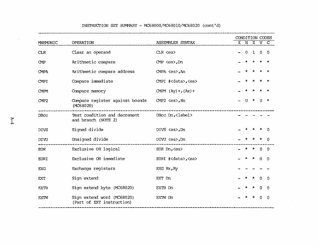
INSTRUCTION SET SUMMARY - MC68000/MC68010/MC68020 (cont'd)
CONDITION CODES MNEMONIC OPERATION ASSEMBLER SYNTAX x N z v c
CLR Clear an operand CLR <ea> 0 1 0 0
CMP Arithmetic compare CMP <ea>,Dn * * * * CMPA Arithmetic compare address CMPA <ea>,An * * * * CMPI Compare immediate CMPI #<data>,<ea> * * * * CMPM Compare memory CMPM (Ay)+,(Ax)+ * * * * CMP2 Compare register against bounds CMP2 <ea>,Rn - u * u *
(MC68020)
DBcc Test condition and decrement DBcc Dn,<label> - - -=r and branch (NOTE 2) ~
DIVS Signed divide DIVS <ea>,Dn * * * 0
DIVU Unsigned divide DIVU <ea>,Dn * * * 0 --------------------------------------------------------------------------------------------------EOR Exclusive OR logical EOR Dn,<ea> * * 0 0
EORI Exclusive OR immediate EORI #<data>,<ea> * * 0 0
EXG Exchange registers EXG Rx,Ry
EXT Sign extend EXT Dn * * 0 0
EXTB Sign extend byte (MC68020) EXTB Dn * * 0 0
EXTW Sign extend word (MC68020) EX'IW Dn * * 0 0 (Part of EXT instruction)

INSTRUCTION SET SUMMARY - MC68000/MC68010/MC68020 (cont'd)
MNEMONIC
JMP
JSR
LEA
LINK
LSL, LSR
MOVE
MOVE to SR
OPERATION
Jump
Jump to subroutine
Load effective address
Link and allocate (NCYrE 5)
Logical shift
Move data from source to destination
Move to the status register
~OVE fran SR Move fran the status register
MOVE to CC M.Jve to condition codes
MOVE from CC Move fr on condition codes (MC68010 or newer)
MOVE USP Move user stack pointer
MOVEA Move address
MOVEC Move to/from control register (MC68010 or newer) (NOTE 3)
ASSEMBLER SYNTAX
JMP <ea>
JSR <ea>
LEA <ea>,An
LINK An,#<disp>
LSd Dx,Dy LSd #<data>,Dy LSd <ea>
MOVE <ea>,<ea>
MOVE <ea>,SR
MOVE SR,<ea>
MOVE <ea>,CCR
MOVE CCR,<ea>
MOVE USP,An MOVE An,USP
MCVEA <ea> ,An
MOVEC Rc,Rn MOVEC Rn,Rc
CONDITION CODES X N Z V C
* * * 0 *
* * 0 0
* * * * *
* * * * *
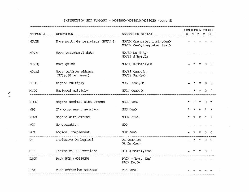
MNEMONIC
MOVEM
MOVEP
MOVEQ
MOVES
MULS
MULU
NBCD
NEG
NEGX
NOP
NOT
OR
ORI
PACK
PE..Z\
INSTRUCTION SET SUMMARY - MC68000/MC68010/MC68020 (cont'd)
OPERATION
Move multiple re<3isters (NOTE 4)
.M:>ve peripheral data
Move quick
Move to/from address (MC68010 or newer)
Signed multiply
Unsigned multiply
Negate decimal with extend
2's complement negation
Ne<Jate with extend
No operation
Logical complement
Inclusive OR logical
Inclusive OR i:mmErliate
Pack BCD (MC68020)
Push effective address
ASSEMBLER SYNTAX
MOVEM <register list>,<ea> MOVEM <ea>,<register list>
MOVEP Dx,d(Ay) MOVEP d (Ay) ,Dx
MOVEQ #<data>,Dn
MOVES <ea>,Rn MOVES Rn,<ea>
MULS <ea>,Dn
MULU <ea>,Dn
NBCD <ea>
NEG <ea>
NEGX <ea>
NOP
NOT <ea>
OR <ea>,Dn OR Dn,<ea>
ORI #<data>,<ea>
PACK -(Ay) ,-(Ax) PACK Dy,Dx
PEA <ea>
CONDITION CODES X N Z V C
* * 0 0
* * 0 0
* * 0 0
* u * u *
* * * * *
* * * * * - - - -
* * 0 0
- * * 0 0
- * * 0 0
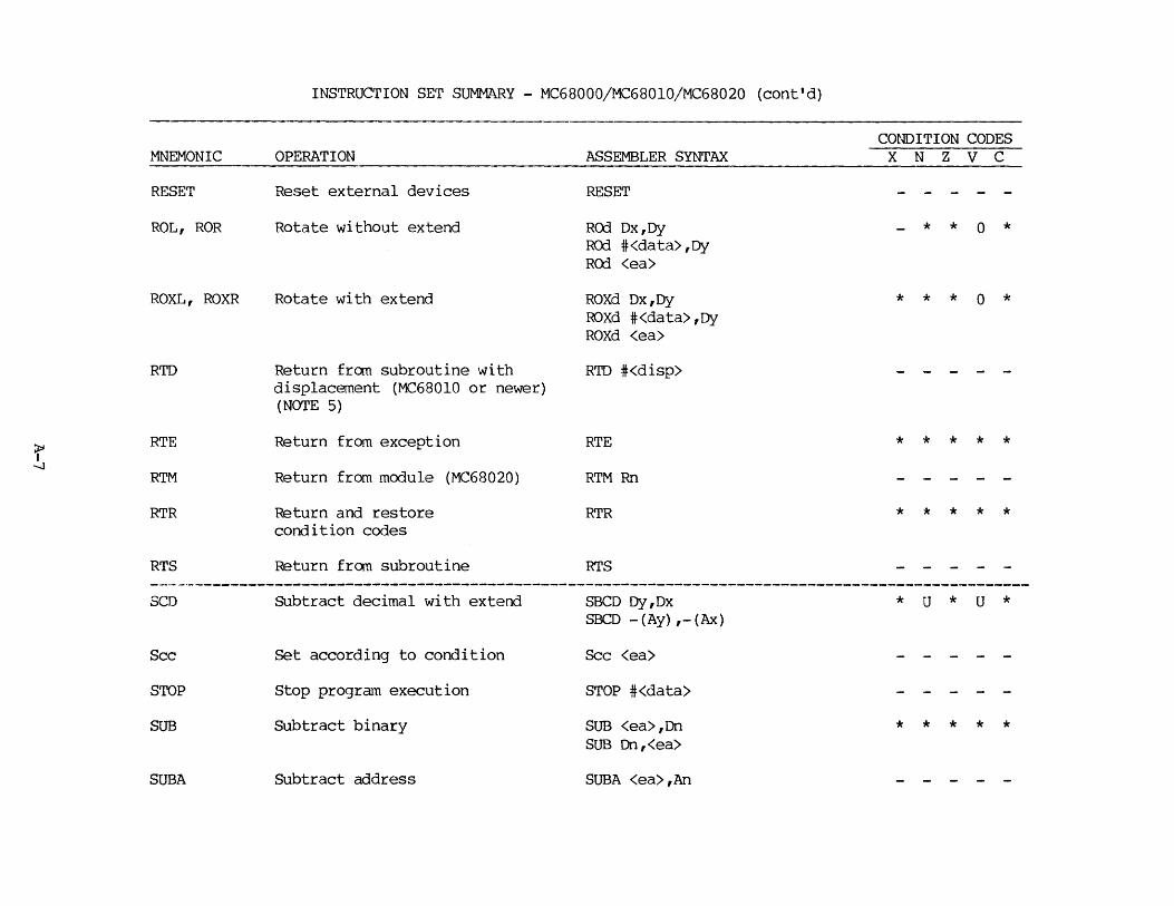
INSTRUCTION SET SUMMARY - MC68000/MC68010/MC68020 (cont'd)
CONDITION CODES MNEMONIC OPERATION ASSEMBLER SYNTAX x N z v c
RESET Reset external devices RESET
ROL, ROR Rotate without extend RO:] Dx,Dy * * 0 * RO:] #<data>,Dy RO:] <ea>
ROXL, ROXR Rotate with extend ROXd Dx,Dy * * * 0 * ROXd #<data>,Dy ROXd <ea>
RTD Return frcm subroutine with RTD #<disp> displacement (MC68010 or newer) (NOTE 5)
RTE Return from exception RTE * * * * * ~ -...J
RTM Return from module (MC68020) RTM Rn
RTR Return and restore RTR * * * * * condition codes
RTS Return frcm subroutine RTS ---------------------------------------------------------------------------------------------------SCD subtract decimal with extend SBCD Dy,Dx * u * u *
SBCD -(Ay),-(Ax)
Sec Set according to condition Sec <ea>
STOP Stop program execution STOP #<data>
SUB Subtract binary SUB <ea>,Dn * * * * * SUB Dn,<ea>
SUBA Subtract address SUBA <ea>,An

INSTRUCTION SET SUMMARY - MC68000/MC68010/MC68020 (cont'd)
CONDITION CODES MNEMONIC OPERATION ASSEMBLER SYNTAX x N z v c
SUB! Subtract immerliate SUB! #<data>,<ea> * * * * * SUBQ Subtract quick SUBQ #<data>,<ea> * * * * * SUBX Subtract with extend SUBX Dy,Dx * * * * *
SUBX -(Ay) ,-(Ax)
SWAP Swap register halves SWAP Dn - * * 0 0
TAS Test and set an operand TAS <ea> * * 0 0
Tee Trap on condition code (MC68020) Tee - - -f TD IVS Truncated signed (MC68020) TD IVS <ea>, {Di: }Dj * * * 0 (X)
TDIVU Truncated unsigned divide (MC68020) TDIVU <ea>,{Di: }Dj * * * 0
TPcc Trap on condition code (MC68020) TPCC #xxx - - -
TRAP Trap TRAP #<vector> - - -
TRAPV Trap on overflow TRAPV - - -
TST Test an operand TST <ea> * * 0 0
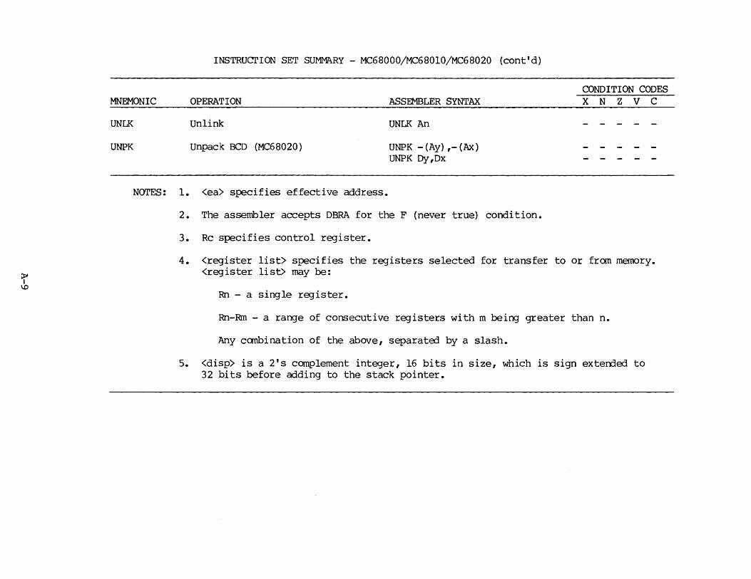
INSTRUcrION SET SUMMARY - MC68000/MC68010/MC68020 {cont'd)
CONDITION CODES MNEMONIC OPERATION ASSEMBLER SYNTAX x N z v c
UNLK Unlink UNLK An - - - - -
UNPK Unpack BCD {MC68020) UNPK -{Ay) ,- {Ax) - - -UNPK Dy,Dx - - -
NOTES: 1. <ea> specifies effective address.
2. The assembler accepts DBRA for the F {never true) condition.
3. Re specifies control register.
4. <register list> specifies the registers selected for transfer to or from memory. <register list> may be:
Rn - a single register.
Rn-Rm - a range of consecutive registers with m being greater than n.
"Any canbination of the above, separated by a slash.
5. <disp> is a 2's complement integer, 16 bits in size, which is sign exterrled to 32 bits before adding to the stack pointer.
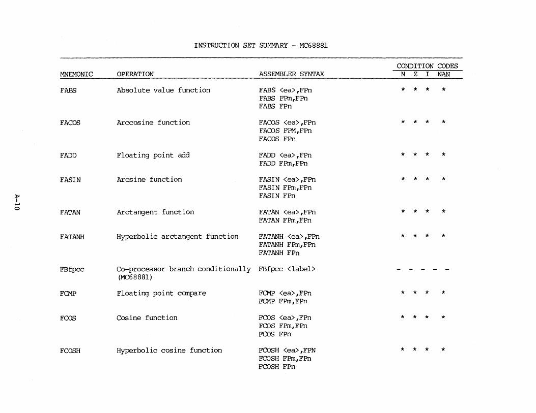
INSTRUcrION SET SUMMARY - MC68881
CONDITION CODES MNEMONIC OPERATION ASSEMBLER SYNTAX N z I NAN
FABS Absolute value function FABS <ea>,FPn * * * * FABS FPrn,FPn FABS FPn
FA COS Arccosine function FACOS <ea>,FPn * * * * FAffiS FPM,FPn FACOS FPn
FADD Floating point add FADD <ea>,FPn * * * * FADD FPm,FPn
FASIN Arcsine function FAS! N <ea> ,FPn * * * * FASIN FPm,FPn
r FASIN FPn I-' 0
FATAN ArctarxJent function FATAN <ea>,FPn * * * * FATAN FPm,FPn
FATANH Hyperbolic arctangent function FATANH <ea>,FPn * * * * FATANH FPm,FPn FATANH FPn
FBfpcc Co-processor branch conditionally FBfpcc <label> (MC68881)
FCMP FloatinJ point canpare FCMP <ea>,FPn * * * * FQ1P FPm,FPn
FCOS Cosine function Fms <ea>,FPn * * * * FCOS FPm,FPn FCOS FPn
FCOSH Hyperbolic cosine function FCOSH <ea>,FPN * * * * FCOSH FPm,FPn FCOSH FPn

INSTRUcrION SET SUMMARY - MC68881 (cont'd)
CONDITION CODES MNEMONIC OPERATION ASSEMBLER SYNTAX N z I NAN
FDBfpcc Decrement arrl branch on condition FDBfpcc DN,<label> - - -(MC68881)
FDIV Floating point divide FDIV <ea>,F~ * * * * FDIV FPm,FPn
FETOX e**x function FETOX <ea>,FPn * * * * FETOX FPm,FPn FETOX FPn
FETOXMl e**x (x-1) function FETOXMl <ea>,FPn * * * * FETOXMl FPm,FPn FETOXMl FPn
~ I FGETEXP Get the exponent function FGETEXP <ea>,FPn * * * * .......
....... FGETEXP FPm,FPn FGETEXP FPn
FGETMAN Get the Mantissa function FGETMAN <ea>,FPn * * * * FGETMAN FPm,FPn FGETMAN FPn
FINT Integer part function FINT <ea>,FPn * * * * FINT FPm,FPn FINT FPn
FLOG2 Binary log function FLOG2 <ea>,FPn * * * * FL<X;2 FPm,FPn FLOG2 FPn
FLOGlO Common log function FLOGlO <ea>,FPn * * * * FL<X;lO FPm,FPn FLOGlO FPn
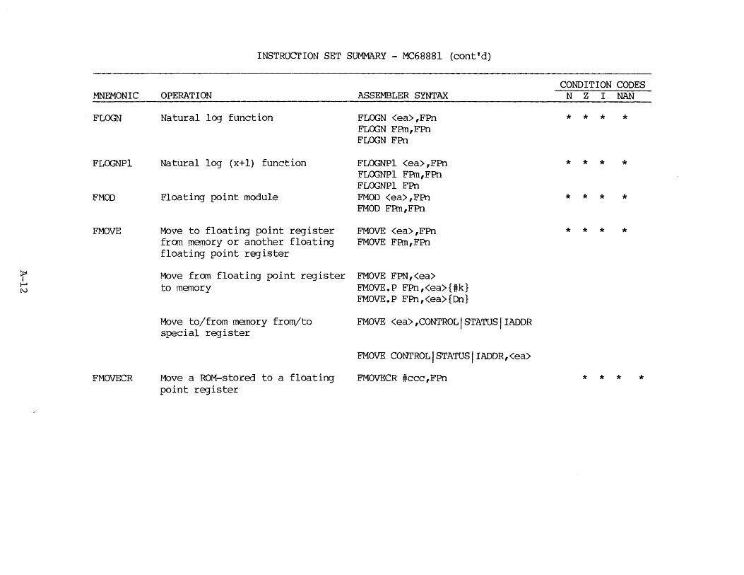
INSTRUCTION SET SUMMARY - MC68881 {cont'd)
CONDITION CODES MNEMONIC OPERATION ASSEMBLER SYNTAX N z I, NAN
FLOGN Natural log function FLOGN <ea>,FPn * * * * FL<X;N FPm,FPn FLOGN FPn
FLOGNPl Natural log {x+l) function FLOGNPl <ea>,FPn * * * * FL(X;NPl FPm,FPn FLOGNPl FPn
FMOD Floating point module FMOD <ea>,FPn * * * * FMOD FPm,FPn
FMOVE Move to floating point register FMOVE <ea>,FPn * * * * fran memory or another floating FMOVE FPm,FPn floating point register
=r Move fran floating point register FMOVE FPN,<ea> ...... to memory FMOVE.P FPn,<ea>{#k} N
FMOVE.P FPn,<ea>{Dn}
Move to/from memory from/to FMOVE <ea>,CONTROLISTATUSIIADDR special register
FMOVE CONTROLISTATUSIIADDR,<ea>
FMOVECR Move a ROM-stored to a floating FMOVECR #ccc ,FPn * * * * point register
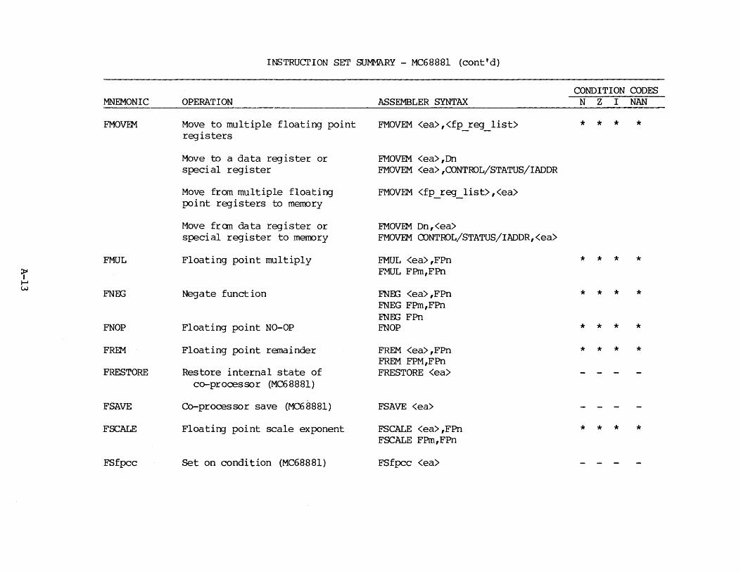
INSTRUcrION SET SUMMARY - MC68881 (cont'd)
CONDITION CODES MNEMONIC OPERATION ASSEMBLER SYNTAX N z I NAN
FMOVEM Move to multiple floating point FMOVEM <ea>,<fp_reg_ list> * * * * registers
Move to a data register or FMOVEM <ea>,Dn special register FMOVEM <ea>,CONTROL/STATUS/IADDR
Move from multiple floating FMOVEM <fp_reg_list>,<ea> point registers to memory
Move fran data register or FMOVEM Dn,<ea> special register to memory FMOVEM CUNTROL/STATUS/IADDR,<ea>
FMUL Floating point multiply FMUL <ea>,FPn * * * * ~ FMUL FPm,FPn I-' w FNEG Negate function FN:&; <ea>,FPn * * * *
FNEG FPm,FPn FNEX; FPn
FNOP Floating point NO-OP FNOP * * * * FREM Floating point remainder FREM <ea>,FPn * * * *
FREM FPM,FPn FRESTORE Restore internal state of FRESTORE <ea> - - -
co-processor (MC68881)
FSAVE Co-processor save (MC68881) FSAVE <ea> - - -
FSCALE Floatinj point scale exponent FSCALE <ea>,FPn * * * * FSCALE FPm,FPn
FSfpcc Set on condition (MC68881) FSfpcc <ea> - - -
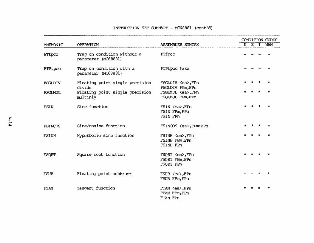
INSTRUcrION SET SUMMARY - MC68881 (cont'd)
CONDITION CODES MNEMONIC OPERATION ASSEMBLER SYNTAX N z I NAN
FI'f pcc Trap on condition without a FI'f pcc - - -parameter (MC68881)
FTPf pcc Trap on corrlition with a FI'Pf pcc #xxx - - -parameter (MC68881)
FSGLDIV Floating point single precision FSGLD IV <ea> ,FPn * * * * divide FSGLDIV FPm,FPn
FSGLMUL Floating point single precision FSGLMUL <ea>,FPn * * * * multiply FSGLMUL FPm,FPn
FSIN Sine function FSIN <ea>,FPn * * * * FSIN FPm,FPn
r FSIN FPn ...... .i:i. FSINCOS Sine/cosine function FSINCOS <ea>,FPm:FPn * * * *
FSINH Hyperbolic sine function FSINH <ea>,FPn * * * * FSINH FPm,FPn FSINH FPn
FSQRT Square root function FSQRT <ea>,FPn * * * * FSQRT FPm,FPn FSQRT FPn
FSUB Floating point subtract FSUB <ea> ,FPn * * * * FSUB FPm,FPn
FI'AN Tangent function FrAN <ea>,FPn * * * * ETAN FPm,FPn FTAN FPn

INSTRUCTION SET SUMMARY - MC68881 (cont'd)
CONDITION CODES MNEMONIC OPERATION ASSEMBLER SYNTAX N z I NAN
FTANH Hyperbolic tangent function FTANH <ea>,FPn * * * * FTANH FPm,FPn FTA.i.~H FPn
FTENTOX lO**x function FTENTOX <ea>,FPn * * * * J~'TENTOX FPm,FPn FTENTOX FPn
FT EST Floating point test an operand FTEST <ea> * * * * F'IWOTOX 2**x function FTWOTOX <ea>,FPn * * * *
FTWOTOX FPm,FPn :r FTWOTOX FPn I-' Ul "'-.. FYTOX Floating point y**x FYTOX <ea>,FPn * * * * :r I-' FYTOX FPm,FPn °'


APPENDIX B
QiARACTER SET
The character set recognized by the Motorola M68000 Family Resident Structured Assembler is a subset of ASCII (American Standard Code for Information Intercharge, 1968). The characters listed below are recognized by the assembler, and the ASCII code is shown on the following pages.
1. The uppercase letters A through Z
2. The lowercase letters a through z (MC68020 assemblers or SYSTEM V /68 only)
3. The integers 0 through 9
4. Four arithmetic operators: + - * /
5. The logical operators: >> << &
6. Parentheses used in expressions ( )
7. Characters used as special prefixes:
# (pound sign) specifies the immErliate mode of addressing $ (dollar sign) specifies a hexadecimal number @ (ccmmercial "at") specifies an octal number % (percent) specifies a binary number ' (apostrophe) specifies an ASCII literal character
8. The special characters used in macros: < > \ @
9. Four separating characters:
(space) (tab) (M68020 assemblers or SYSTEM V/68 only)
, (canma) • (period)
10. A comnent in a source statement may include any characters with ASCII hexadecimal values fran 20 (SP} through 7E (-).
11. Character used as a special suffix:
: (colon) specifies the errl of a label
B-1

CHARACTER
NUL
SOH
STX
ETX
EOT
ENQ
ACK
BEL
BS
HT
LF
VT
FF
RE'IURN
so SI
OLE
OCl
DC2
DC3
DC4
NAK
SYN
ETB
CAN
EM
SUB
ESC
FS
GS
RS
us
ASCII Character Set
COMMENTS
Null or tape feed
Start of Heading
Start of Text
End of Text
Errl of Transmission
Enquire (who are you, WRU)
Acknowledge
Bell
Backspace
Horizontal Tab
Line Feed
Vertical Tab
Form Feed
Carriage Return
Shift Out (to red ribbon)
Shift In (to black ribbon)
Data Link Escape
Device Control 1
Device Control 2
Device Control 3
Device Control 4
Negative Acknowledge
Synchronous idle
End of Transmission Block
Cancel
End of Merli um
Substitute
Escape, prefix
File Separator
Group Separator
Record Separator
Unit Separator
B-2
HEX VALUE
00
01
02
03
04
05
06
07
08
09
OA
OB
oc OD
OE
OF
10
11
12
13
14
15
16
17
18
19
lA
lB
lC
lD
lE
lF
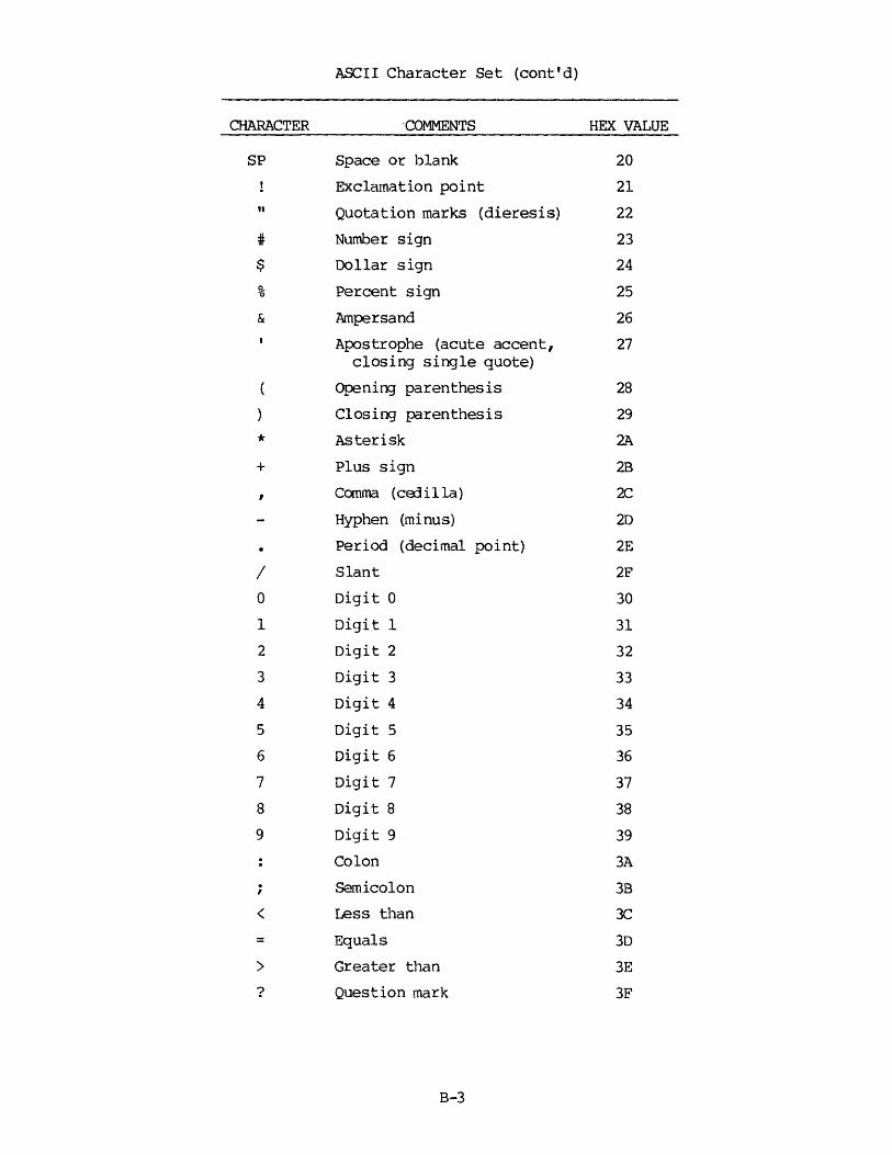
ASCII Character Set (cont'd)
CHARACTER ·COMMENTS HEX VALUE
SP Space or blank 20
Exclamation point 21
" Quotation marks (dieresis) 22
# Number sign 23
$ Dollar sign 24
% Percent sign 25
& Ampersand 26
Apostrophe (acute accent, 27 closing single quote)
Opening parenthesis 28
Closing parenthesis 29
* Asterisk 2A
+ Plus sign 2B
, Comma (cErlilla) 2C
Hyphen (minus) 2D
Period (decimal point) 2E
I Slant 2F
0 Digit 0 30
1 Digit 1 31
2 Digit 2 32
3 Digit 3 33
4 Digit 4 34
5 Digit 5 35
6 Digit 6 36
7 Digit 7 37
8 Digit 8 38
9 Digit 9 39
Colon 3A
; Semicolon 3B
< Less than 3C
= Equals 3D
> Greater than 3E
? Question mark 3F
B-3

ASCII Character Set (cont'd)
CHARACTER COMMENTS HEX VALUE
@ Conmercial at 40
A Upp:rcase letter A 41
B Uppercase letter B 42
c Upp:rcase letter C 43
D Uppercase letter D 44
E Upp:rcase letter E 4S
F Uppercase letter F 46
G Uppercase letter G 47
H Uppercase letter H 48
I Uppercase letter I 49
J Uppercase letter J 4A
K Upp:rcase letter K 4B
L Uppercase letter L 4C
M Upp:rcase letter M 40
N Uppercase letter N 4E
0 Uppercase letter 0 4F p Uppercase letter p 50
Q Upp:rcase letter Q Sl
R Uppercase letter R 52
s Uppercase letter s 53
T Uppercase letter T S4
u Upp:rcase letter U 55
v Uppercase letter V 56
w Uppercase letter W S7
x Uppercase letter X S8 y Uppercase letter Y 59
z Uppercase letter z SA
[ Opening bracket SB
\ Reverse slant SC
Closing bracket SD
Circumflex SE
Underline SF
B-4
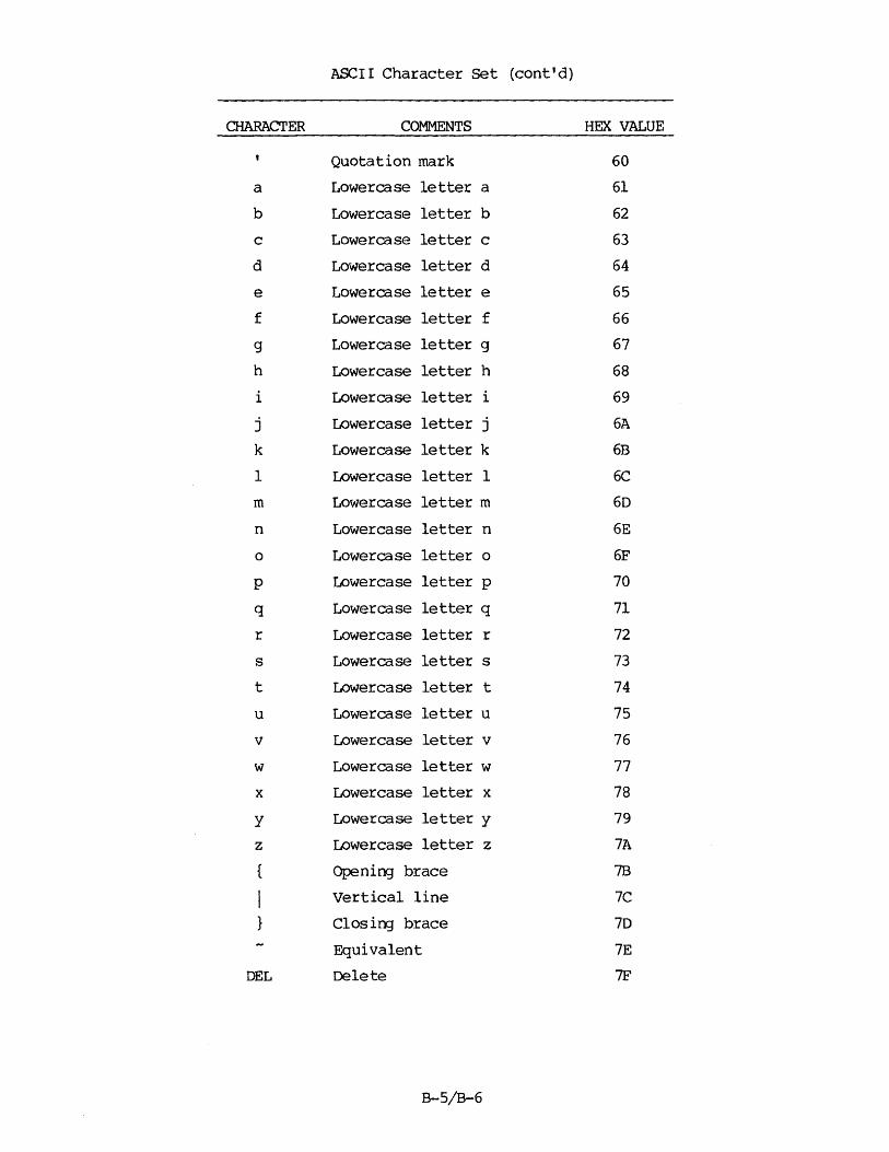
ASCII Character Set (cont'd)
CHARACTER COMMENTS HEX VALUE
Quotation mark 60
a Lowercase letter a 61
b Lowercase letter b 62
c Lowercase letter c 63
d Lowercase letter d 64
e Lowercase letter e 65
f Lowercase letter f 66
g Lowercase letter g 67
h Lowercase letter h 68
i Lowercase letter i 69
j Lowercase letter j 6A
k Lowercase letter k 6B
1 Lowercase letter 1 6C
m Lowercase letter m 60
n Lowercase letter n 6E
0 Lowercase letter o 6F
p Lowercase letter p 70
q Lowercase letter q 71
r Lowercase letter r 72
s Lowercase letter s 73
t Lowercase letter t 74
u Lowercase letter u 75
v Lowercase letter v 76
w Lowercase letter w 77
x Lowercase letter x 78
y Lowercase letter y 79
z Lowercase letter z 7A
{ Opening brace 7B
I Vertical line 7C
} Closing brace 70
Equivalent 7E
DEL Delete 7F
B-5/B-6


APPENDIX C
SAMPLE ASSEMBLER OUTPUT
MOTOROLA M68000 A.SM FIX 108.DEMO .MAIN .SA
1 2 3 4 5 6 7 8 9
10 11 12 13 14 15 16 17 18 19 20 21 22 23 24 25 26 27 28 29 30 31 32 33 34 35 36 37 38 39 40 41 42 8 43
00000000 00000002 00000002 00000002 00000004 00000002 00000006 00000002 00000008 00000002
00000008 00000000
44 8 00000000 5346 45 8 00000002 33C600000000
* MAIN *
IDNT 2,3 Demonstration Program
* * * * * * *
'lllis program counts occurrences of vowels (A,E,I,O,U) in the conmand line and outputs an error if fewer than 10 vowels are found in the conmand line, aside from the vowels in the program name 'TSTPRCXi'. It is written in a contrived fashion to illustrate several features of the M68000 assembler.
*
OPT OPT
XREF.S XREF.S XREF XREF
CRE MEX
15:VCWEL 15:STACK FINDV CMDLEN
Create a cross-reference listing Enable macro expansions
Array containing vowel count info Scratch stack space Routine that does the counting Length of the corcmand line
* * * * *
'lbese are offsets into the vowel array contained in module FINDV. Each entry in this array contains 1 byte for the vowel's name and one byte for the count of occurrences of the vowel.
OFFSET 0 A DS.W 1 E DS.W 1 I OS.W 1 0 DS.W 1 U DS.W 1 * * 'Ibis macro calls FINDV to count occurrences of the vowel * contained in argument 1. It then adds that subtotal into * the running total contained in 01. * CHKVCJ-JEL MACRO
MOVE.B JSR ADO.B ENDM
*
#\1,DO FINDV \l+ 1 (AO) ,Dl
START SECTION 8 EQU * SUB.W MOVE.W
U,D6 D6,CMDLEN
Store current vowel offset into VOdEL Find all occurrences of it Add this to the total vowel count
Index corcmand line from offset 0 and not 1 Save the comnand line len
46 * as passed by VERSAdos 47 8 00000008 4FF80000 48 8 OOOOOOOC 41F80000 49 8 00000010 4241 50 8 00000012 4280 51 52 8 00000014
53
8 00000014 103COOOO 8 00000018 4EB900000000 8 OOOOOOlE 02280001
54 8 00000022
55
8 00000022 103C0002 8 00000026 4EB900000000 8 0000002C 02280003
LEA LEA CLR.W CLR.L
STACK,A7 VOIJEL,AO 01 DO
CHKVCWEL A MOVE.B #A,DO JSR FINDV ADO.B A+l(AO),Dl
CHKVOIIBL E MOVE.B #E,DO JSR FINDV ADD.B E+l(AO) ,Dl
C-1
Initialize the stack area Start of the vowel table current total vowel count Will hold offset to current char later
Store current vowel offset into VCWEL Find all occurrences of it Add this to the total vowel count
Store current vowel offset into VCWEL Find all occurrences of it Add this to the total vowel count

56 8 00000030
57
8 00000030 103C0004 8 00000034 4EB900000000 8 0000003A 02280005
58 8 0000003E
59
8 0000003E 103C0006 8 00000042 4EB900000000 8 00000048 02280007
60 8 0000004C
61 62
8 0000004C 103C0008 8 00000050 4EB900000000 8 00000056 02280009
63 8 00000060 3041 64 8 00000062 700E 65 8 00000064 4E41 66 8 00000066 0000 67 68 69 8 00000068 700F 70 8 0000006A 4E41 71 72 8 00000000
****** TCJrAL ERRORS O~ ****** TO'I'AL WARNINJS 0--
SYMBOL TABLE LISTINJ
SYMBOL NAME SECT VALUE
A 00000000 CHKVG/EL MACR * CMDLEN XREF * 00000000 E 00000002 FINOV XREF * 00000000 I 00000004 0 00000006 STACK XREF F 00000000 START 8 00000000 u 00000008 VONEL XREF F 00000000 Z Ll.000 8 00000068
CHKVClllEL I MOVE.B #I,00 JSR FINDV ADO.B I+l(AO) ,Dl
CHKVCJflEL 0 MOVE.B #0,DO JSR FINDV ADO.B o+l(AO) ,Dl
CHKVClllEL U MOVE.B #U,00 JSR FINDV ADD.B U+l(AO) ,Dl
IF .B #10 <GT> 01 THEN.S MOVE.W Dl,AO MOVE.L #14,00 TRAP #1 oc.w 0
ENDI
MOVE.L #15,00 TRAP #1
END START
CROSS-REF (LINENUMBERS)
-24 52 -34 11 52 54 56 -17 45 -25 54 -16 52 54 56 58 -26 56 -27 58 -15 47 -42 72 -28 60 -14 48 -67 62
C-2
Store current vowel offset into VCl\'EL Find all occurrences of it Add this to the total vowel count
Store current vowel offset into V(ltlEL Find all occurrences of it Add this to the total vowel count
Store current vowel offset into VCl\'EL Find all occurrences of it Add this to the total vowel count
Not enough vowels
generate error showing # of vowels found
Exit gracefully if all is OK
58 60
60
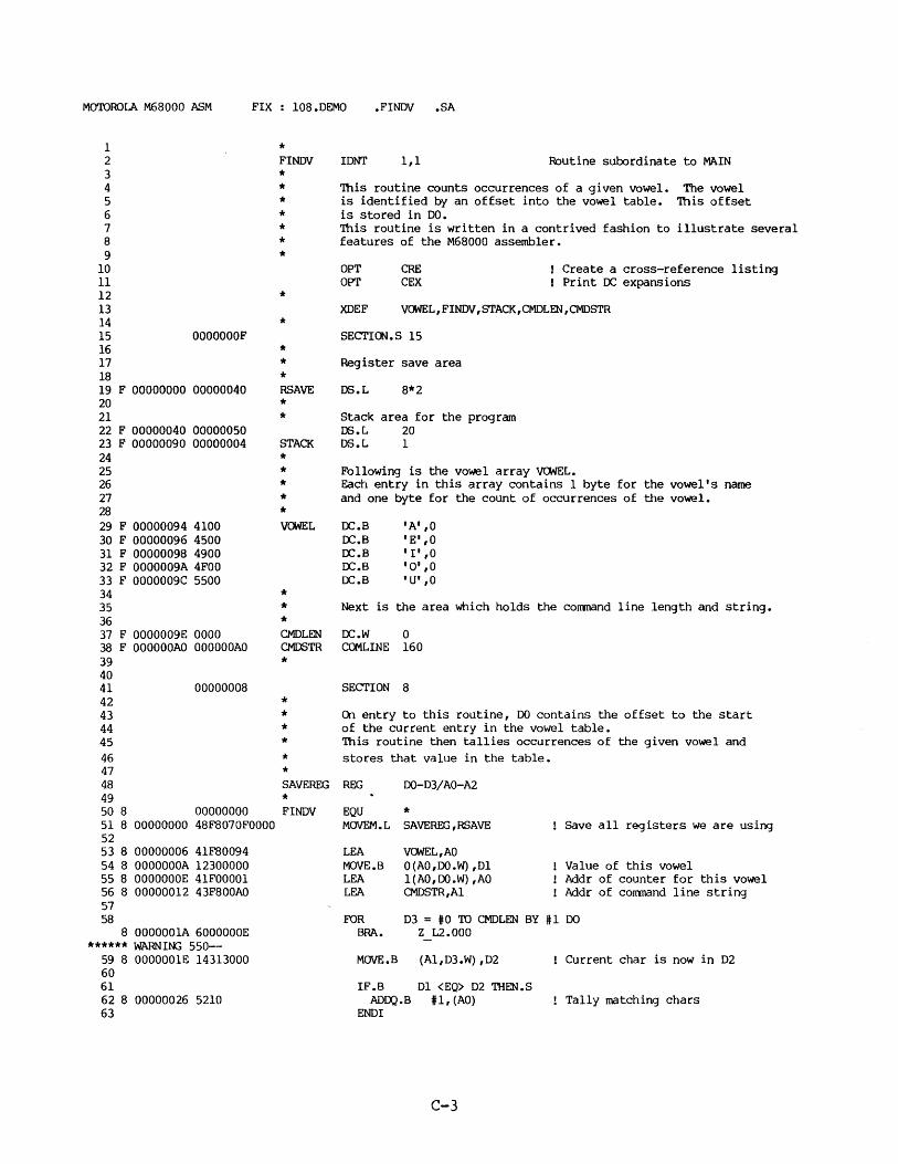
MOTOROLA M68000 ASM FIX 108.0EMO .FINDV .SA
1 2 3 4 5 6 7 8 9
10 11 12 13 14 15 OOOOOOOF 16 17 18 19 F 00000000 00000040 20 21 22 F 00000040 00000050 23 F 00000090 00000004 24 25 26 27 28 29 F 00000094 4100 30 F 00000096 4500 31 F 00000098 4900 32 F 0000009A 4FOO 33 F 0000009C 5500 34 35 36 37 F 0000009E 0000 38 F OOOOOOAO OOOOOOAO 39 40 41 00000008 42 43 44 45 46 47 48 49 50 8 00000000 51 8 00000000 48F8070FOOOO 52 53 8 00000006 41F80094 54 8 OOOOOOOA 12300000 55 8 OOOOOOOE 41F00001 56 8 00000012 43F800AO 57 58
8 OOOOOOlA 6000000E ****** WARNil'Ki 550--
59 8 OOOOOOlE 14313000 60 61 62 8 00000026 5210 63
* FINDV IDNT 1,1 Routine subordinate to MAIN * * 'Ihis routine counts occurrences of a given vowel. The vowel * is identified by an offset into the vowel table. 'Ihis offset * is stored in DO. * 'Ihis routine is written in a contrived fashion to illustrate several * features of the M68000 assembler. *
*
OPT OPT
CRE CEX
Create a cross-reference listing Print DC expansions
XDEF V~L,FINDV,STACK,CMDLEN,CMDSTR
* SECTIOO.S 15
* * Register save area * RSAVE * * STACK
*
DS.L 8*2
Stack area for the program DS.L 20 OS.L 1
* Following is the vowel array VCJNEL. * Each entry in this array contains 1 byte for the vowel's name * and one byte for the count of occurrences of the vo'Wel. * VCMEL
*
DC.B DC.B DC.B DC.B DC.B
'A' ,O IE' ,o I I' ,o '0' ,o 'U' 1 0
* Next is the area which holds the corrmand line length and string. * CMDLEN DC.W 0 CMDSTR COMLINE 160
* SECTION 8
* * On entry to this routine, DO contains the offset to the start * of the current entry in the vowel table. * This routine then tallies occurrences of the given vowel and * stores that value in the table. * SAVEREG REG D0-03/AO-A2 * FINDV EQU *
MOVEM.L SAVEREG,RSAVE
LEA MOVE.B LEA LEA
VCJNEL,AO O(AO,DO.W),01 l(AO,DO.W) ,AO CMDSTR,Al
Save all registers we are using
Value of this vowel Addr of counter for this vowel Addr of corrrnand line string
FOR 03 = #0 TO CMDLEN BY U DO BRA. Z L2.000
MOVE.B (Al,D3.W),D2 Current char is now in D2
IF.B Dl <EQ> 02 THEN.S AD))'J.B U, (AO) Tally matching chars
ENDI
C-3
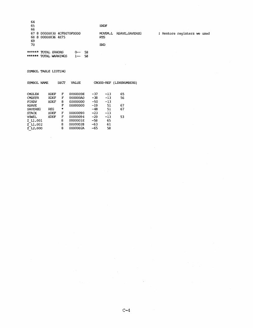
64 65 ENDF 66 67 8 00000030 4CF8070FOOOO MOVEM.L RSAVE,SAVEREG Restore registers we used 68 8 00000036 4E75 Rl'S 69 70 END
****** TOTAL ERRORS 0-- 58 ****** TOI'AL WARNI~S 1- 58
SYMBOL TABLE LISTING
SYMBOL NAME SECT VALUE CROSS-REF { LINENUMBERS)
CMDLEN XDEF F 0000009E -37 -13 65 CMDSTR XDEF F OOOOOOAO -38 -13 56 FINDV XDEF 8 00000000 -50 -13 RSAVE F 00000000 -19 51 67 SAVEREG REG * -48 51 67 STACK XDEF F 00000090 -23 -13 VCl<JEL XDEF F 00000094 -29 -13 53 Z Ll.001 8 OOOOOOlE -58 65 Z-Ll.002 8 00000028 -63 61 Z-L2.000 8 0000002A -65 58
C-4
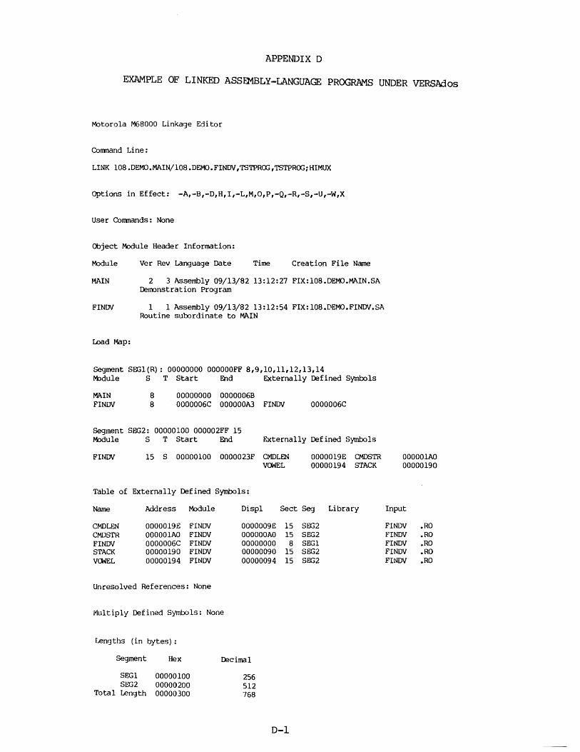
APPENDIX D
EXAMPLE OF LINKED ASSEMBLY-LANGUAGE PROGRAMS UNDER VERSAdos
Motorola M68000 Linkage Editor
Corrmand Line:
LINK 108.DEMO.MAIN/108.DEMO.FINDV,TSTPR(Xj,TSTPR(Xj;HIMUX
Options in Effect: -A,-B,-D,H,I,-L,M,O,P,-Q,-R,-S,-U,-W,X
User Comnands: None
Object Module Header Information:
Module Ver Rev Language Date Time Creation File Name
MAIN 2 3 Assembly 09/13/82 13:12:27 FIX:l08.DEMO.MAIN.SA Demonstration Program
FINDV 1 1 Assembly 09/13/82 13:12:54 FIX:l08.DEMO.FINDV.SA Routine subordinate to MAIN
Load Map:
Segment SEX.il(R}: 00000000 OOOOOOFF 8,9,10,11,12,13,14 r-t>dule S T Start End Externally Defined Symbols
MAIN FINDV
8 8
00000000 00000068 0000006C OOOOOOA3 FINDV
Segment SEG2: 00000100 000002FF 15
0000006C
l'-t>dule S T Start End Externally Defined Symbols
FINDV 15 S 00000100 0000023F CMDLEN VOi/EL
Table of Externally Defined Symbols:
0000019E CMDSTR 00000194 STACK
Name Address Module Displ Sect Seg Library
CMDLEN 0000019E FINDV 0000009E 15 CMDSTR OOOOOlAO FINDV OOOOOOAO 15 FINDV 0000006C FINDV 00000000 8 STACK 00000190 r'INDV 00000090 15 VOtlEL 00000194 FINDV 00000094 15
Unresolved References: None
Multiply Defined Symbols: None
Lengths (in bytes}:
Segment Hex
SEGl 00000100 SEG2 00000200
Total Length 00000300
Decimal
256 512 768
D-1
SEG2 SEG2 SEGl SEG2 SEG2
OOOOOlAO 00000190
Input
FINDV .RO FINDV .RO FINDV .RO FINDV .RO FINDV .RO
No Errors No warnings
Load module has been created.
D-2
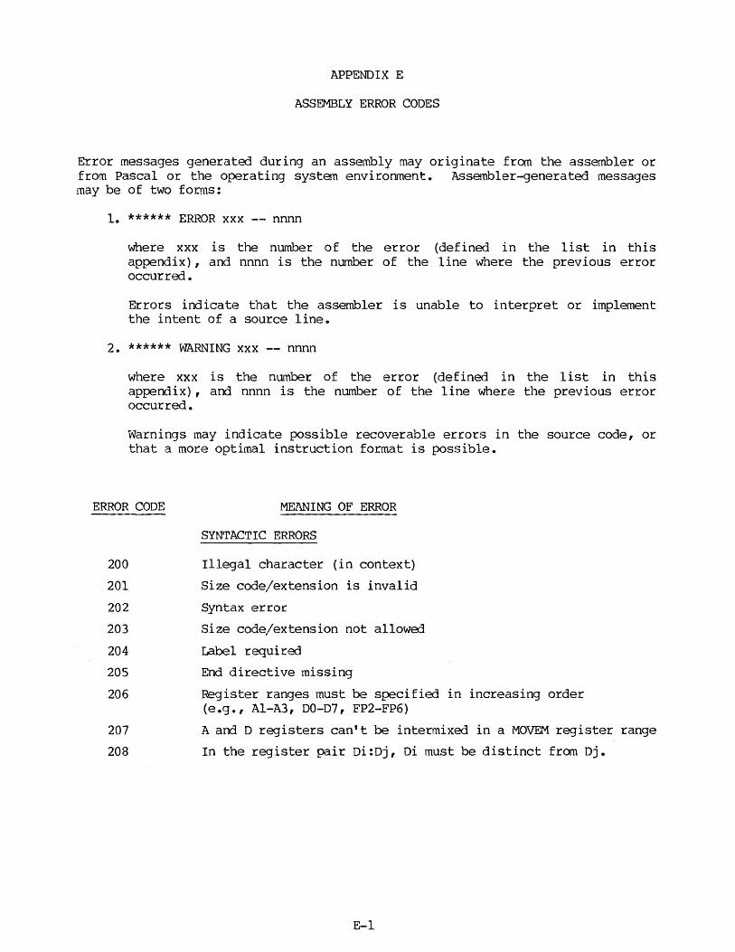
APPENDIX E
ASSEMBLY ERROR CODES
Error messages generated during an assembly may originate from the assembler or from Pascal or the operating system environment. Assembler-generated messages may be of two forms:
1. ****** ERROR xxx -- nnnn
where xxx is the number of the error (defined in the list in this appendix), and nnnn is the number of the line where the previous error occurred.
Errors indicate that the assembler is unable to interpret or implement the intent of a source line.
2. ****** WARNING xxx -- nnnn
where xxx is the number of the error (defined in the list in this appendix), and nnnn is the number of the line where the previous error occurred.
Warnings may indicate possible recoverable errors in the source code, or that a more optimal instruction format is possible.
ERROR CODE
200
201
202
203
204
205
206
207
208
MEANING OF ERROR
SYNTACTIC ERRORS
Illegal character (in context)
Size code/extension is invalid
Syntax error
Size code/extension not allowed
Label required
End directive missing
Register ranges must be specified in increasing order (e.g., Al-A3, 00-07, FP2-FP6)
A and D registers can't be intermixed in a MOVEM register range
In the register pair Di:Dj, Di must be distinct from Dj.
E-1
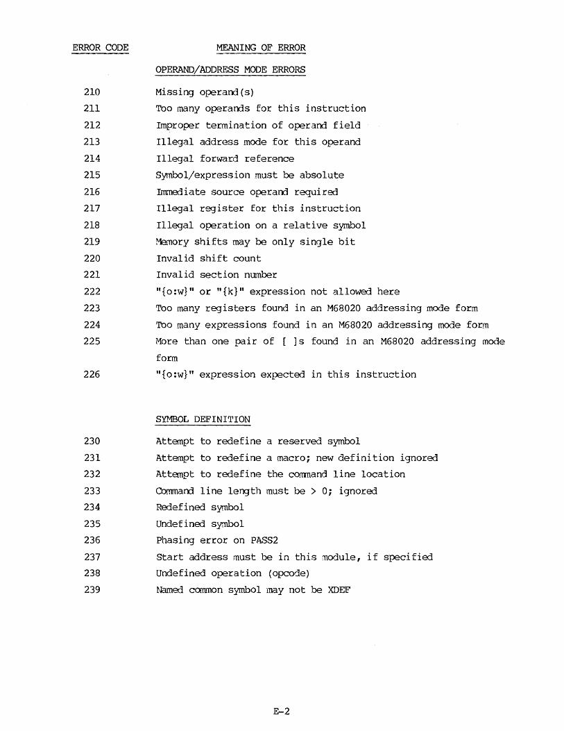
ERROR CODE
210
211
212
213
214
215
216
217
218
219
220
221
222
223
224
225
226
230
231
232
233
234
235
236
237
238
239
MEANING OF ERROR
OPERAND/ADDRESS MODE ERRORS
Missing operand(s)
Too many operands for this instruction
Improper termination of operand field
Illegal address mode for this operand
Illegal forward reference
Symbol/expression must be absolute
Immediate source operand required
Illegal register for this instruction
Illegal operation on a relative symbol
Met~ory shifts may be only single bit
Invalid shift count
Invalid section number
"{o:w}" or "{k}" expression not allowed here
Too many registers found in an M68020 addressing mode form
Too many expressions found in an M68020 addressing mode form
More than one pair of [ ]s found in an M68020 addressing mode
form
"{o:w}" expression expected in this instruction
SYMBOL DEFINITION
Attempt to redefine a reserved symbol
Attempt to redefine a macro; new definition ignored
Attempt to redefine the comnand line location
Commarrl line length must be > O; ignored
Redefined symbol
Undefined symbol
Phasing error on PASS2
Start address must be in this module, if specified
Undefined operation (opcode)
Named common symbol may not be XDEF
E-2

ERROR CODE
250
251
252
253
254
255
256
257
260
261
262
263
264
265
266
267
270
271
MEANING OF ERROR
DATA SIZE RESTRICTIONS
Displacement size error
Value too large
Address too large for forced absolute short
Byte mode not allowed for this opcode
Multiplication overflow
Division by zero
Value out of range
Branch to odd address detected
MACRO ERRORS
Misplaced MACRO, MEXI'r, or ENDM directive
Macro definitions may not be nested
Illegal parameter designation
A period may occur only as the first character in a macro name
Missing parameter reference
Too many parameters in this macro call
Reference precedes macro definition
overflow of input buffer during macro text expansion
CONDITIONAL ASSEMBLY ERRORS
Unexpected 'ENOC'
Bad ending to conditional assembly structure (ENDC expected)
E-3

ERROR CODE
280
281
282
283
284
285
286
287
288
289
290
291
292
300
301
302
303
304
305
310
311
312
313
314
.. ~· . -. ' .
MEANING OF ERROR
STRUCTURED SYNTAX ERRORS
Misplaced structured control directive (ignored)
Missing "END!"
Missing "ENDF"
Missing "ENDW''
Missing "UNTIL"
Unresolved syntax structured control
error in directive;
the precejing para11eterized recovery attempted with the
current line
"=" Expected; characters up to "=" ignored
"<" Expected; characters up to "<" ignored ")II Expected; characters up to ">" ignored
"DO" expected; r1:rna i nder of line ignored
"THEN" expectoo; remainder of line ignored
"TO" or "OOWNTO" expected; "TO" assu.11ed
Illegal condition cod.e specified
MISCELLANEOUS
Implementation restriction
Too many relocatable symbols referenced <linkage editor restricted>
Relocation of byte field attempted
Absolute section of length zero defined (link error)
Nested "INCLUDE" files not allowed; ignored
File na~e required in operand field
Ille1al syntax for "P=nnnnn' option - option ignored
Illegal processor number for 'P=nnnnn' option - option ignored
Processor option does not agree with command line option -option ignored
~1is directive is not valid for the processor that is currently specified.
An "O.FFSET11 block must be followed by an "ORG" or "SECTION" before more code is generated.
E-4

ERROR CODE
330
331
332
333
334
400
499
500
501
502
503
504
550
551
552
553
MEANING OF ERROR
FLOATING POINT ERRORS
Type (size) incompatibility exists between an operand and the opcode size.
Exponent string is too long. Will be truncated on the right which will almost certainly return the wrong value.
A non-decimal character was found in the decimal string. The haracter will be ignored and the conversion will continue although the results should be highly suspect.
The input decimal string is too big to be represented in the specified size. Infinity or the largest positive or negative number will be returned depending on the sign and current rounding mode.
The input decimal string is too small to be represented in the specified size. It was denormalized or reduced to zero.
INTERNAL ERRORS
SOURCE CODE NOT OPTIMAL OR RECOVERABLE ERRORS
This byte will be sign-extended to 32 bits
Missing parameter reference in macro source
Too many parameters in this macro call
Warning - processor type should not be changed after any executable code is generated
Warning - processor type should not be changed after the user once sets it
This branch can also allow a word extension
This absolute address could be short
This expression/displacement could be represented in 16 bi ts
rather than 32 bits.
Warning - this instruction may cause a branch to an odd address
E-5

ERROR CODE
700
701
702
703
MEANING OF ERROR
FLOATING POINT WARNINGS
Mantissa string is too long. digits.
It will be truncated after 17
Decimal strings can be guaranteed to be accurate only to double precision in the worst case. In the best case, they are accurate to extended precision.
The decimal string to fp conversion was inexact (some rounding error occurred). This may or may not be important to the user.
Use of the L, D, x, and P extensions in the FSGLDIV and FSGLMUL instructions may result in a loss of accuracy.
NOTE
If more than 10 errors occur in one line, the message
***** too many errors on this line
will be generated.
E-6

SUGGESTION/PROBLEM REPORT
MS OUM.ITV • PEOPLE • PERFORMANCE
Motorola welcomes your comments on its products and publications. Please use this form.
To: Motorola Inc. Microsystems 2900 S. Diablo Way Tempe, Arizona 85282
Attention: Publications Manager Maildrop DW164
Product:---------------
Please Print
Name _______________ _
Company ______ ~,------~
Street----------------
City----------------
Manual:----------------
Title----------------
Division---------------
Mail Drop _____ Phone-------
State _________ Zip ____ _
For Addttlonal Motorola Publlcatlons Literature Distribution Center
Four Phue/Motorola Customer Support, Tempe Operations (800) 528-1908
616 West 24th Street (602) 438-3100 Tempe, AZ. 85282 (602) 994-6561
®MOTOROLA

16867 PRINTED IN USA (6/84) MESSENGER 5M