m620 maintenance of road safety barrier systems · rms qa specification m620 . maintenance of road...
TRANSCRIPT

RMS QA SPECIFICATION M620
MAINTENANCE OF ROAD SAFETY BARRIER SYSTEMS
NOTICE
This document is a Roads and Maritime Services QA Specification. It has been developed for use with roadworks and bridgeworks contracts let by Roads and Maritime Services or by local councils in NSW. It is not suitable for any other purpose and must not be used for any other purpose or in any other context.
Copyright in this document belongs to Roads and Maritime Services.
REVISION REGISTER
Ed / Rev Number
Clause Number Description of Revision Authorised
By Date
Ed 1/Rev 0 First edition. GM, IC 04.08.08
Edition 1 / Revision 0 ROADS AND MARITIME SERVICES NSW July 2008


RMS QA SPECIFICATION M620
MAINTENANCE OF ROAD SAFETY BARRIER SYSTEMS
GUIDE NOTES (Not Part of Contract Document)
THESE NOTES ARE NOT PART OF THE SPECIFICATION, CONTRACT OR AGREEMENT. The following notes are intended to provide guidance to RMS personnel on the application of the Specification. They do not form part of the Specification, Contract or Agreement.
USING RMS M620 This specification has been specifically developed for RMS maintenance works. It should not be used without a review of its suitability for the application and the contractual environment. RMS R132 should be used for construction of new road safety barrier systems.
RMS M620 is a QA specification. The use of QA specifications requires the implementation of a quality system by the service provider which meets the quality system requirements specified in RMS Q.
RMS M620 must not be used without reference to AS/NZS 3845 “Road safety barrier systems”. Users must have a thorough knowledge and understanding of the provisions of this Standard and Section 6 of the RMS Road Design Guide.
EDITION 1 This is the first edition of the specification. Further improvement and upgrading based on field experience is expected. Comments and suggestions for improvement should be forwarded to the Delivery & Performance Manager, Regional Maintenance Delivery, Asset Maintenance.
The technical content of M620 is similar to that contained in RMS R132.
OUTLINE RMS M620 Maintenance of Road Safety Barrier Systems has been written for safety barrier works involving routine servicing, repairs or replacement of parts of safety barriers at different locations. The existing safety barrier may be of any type of public domain or proprietary system. The specification is based on Specification RMS R132.
RMS M620 specifies all requirements for maintenance of road safety barrier systems on site including traffic management, routine servicing, repair, demolition, removal, excavation and replacement of damaged or deteriorated components. Concrete supply must be separately specified using Specification RMS 3201 Concrete for Maintenance.
RMS M620 is NOT SUITABLE for: • work on bridges other than the replacement of a transition where the only activity involving
the bridge structure is the removal and replacement of the bolts attaching the transition to the bridge; or
Ed 1 / Rev 0 Notes page 3

(RMS COPYRIGHT AND USE OF THIS DOCUMENT – Refer to the Foreword) M620 Maintenance of Road Safety Barrier Systems
• construction of a road safety barrier system in a new location. • full replacement of an existing safety barrier system.
TECHNICAL REFERENCE NOTES Technical information on road safety barrier systems is available in the RMS “Road Design Guide”, in AS/NZS 3845 “Road safety barrier systems” and in various RMS Technical Directions. A list of safety barrier product that is accepted for use by RMS on the Classified Road network is available from the RMS Manager, Technology Standards (Road). Modifications to the accepted system are not permitted without RMS approval and should modifications be planned, the modified system will require further assessment to ensure that the revised system meets RMS requirements.
Clause 1 General
The standards and specifications listed in Annexure M are those quoted in RMS M620. Other standards and specifications will also apply including technical, environmental and work health and safety documents called up in the referenced standards, drawings, specifications or quoted elsewhere in the contract documents.
When Project Specific amendments are made to RMS M620 and these amendments quote other standards, specifications or test methods these further documents should be listed in Annexure M, as appropriate.
Clause 1.2 makes it clear that existing road safety barrier systems are to be maintained in a serviceable condition. This may need to be modified for specific projects or installations. As an example, the Contractor should be notified in advance of any existing road safety barrier systems which are to be modified or replaced so that maintenance is limited to that which is necessary to keep the system serviceable for a short term. Further advice is contained in the last two paragraphs of Clause B2.1 of AS/NZS 3845.
Clauses 4.1.3 and 4.1.4 include the term “Clear Zone”. This term is defined (but not quantified) in AS/NZS 3845. The width of the clear zone may be determined by referring to Section 3.6.1 of the RMS Road Design Guide. Information on the use of this concept in the design of road safety barrier system installations is included in to Section 6 of the RMS Road Design Guide.
Clause 4 Replacement of road safety barrier systems
Consideration should be given to the requirements for repair or replacement of an existing road safety barrier system. It is very important to ensure that this is carried out in each case as the Specification contains no provisions for non-complying systems. AS/NZS 3845 contains useful advice on dealing with this matter.
The continuing need for the system should be among the matters considered - in some cases the removal of the system may reduce the hazard and in others the hazard which led to the installation of the system may have been removed or could now be removed at a lower cost than the cost of replacing the system.
Annexure M620/M – Drawings
The Drawings listed relate to post and beam systems only as these are the most likely drawings to be needed by the Contractor.
Where concrete road safety barrier systems may need major repair or replacement the appropriate drawings should be added to the list and issued with the contract.
Notes page 2 Ed 1 / Rev 0
QA SPECIFICATION M620
MAINTENANCE OF ROAD SAFETY BARRIER SYSTEMS
Copyright – Roads and Maritime Services IC-QA-M620
VERSION FOR: DATE:
Edition 3 / Revision 0 ROADS AND MARITIME SERVICES April 2013


(RMS COPYRIGHT AND USE OF THIS DOCUMENT – Refer to the Foreword) Maintenance of Road Safety Barrier Systems M620
CONTENTS FOREWORD............................................................................................................................................................... II
1 GENERAL ...................................................................................................................................................... 1
2 PLANNING ..................................................................................................................................................... 2
2.1 Project quality plan requirements ................................................................................................ 2
2.2 Setting out ................................................................................................................................... 3
2.3 Replacement components ............................................................................................................ 3
2.4 Sequence of work ........................................................................................................................ 4
3 RESOURCES ................................................................................................................................................... 4
3.1 Identification of materials ............................................................................................................ 4
3.2 Steel ............................................................................................................................................. 5
3.3 Concrete ...................................................................................................................................... 5
3.4 Reinforcing steel .......................................................................................................................... 5
3.5 Timber ......................................................................................................................................... 5
3.6 Aluminium ................................................................................................................................... 6
3.7 Retroreflective materials ............................................................................................................. 6
4 EXECUTION ................................................................................................................................................... 6
4.1 General ........................................................................................................................................ 6
4.2 Removal of Road Safety Barrier Systems ................................................................................... 7
4.3 Replacement of Road Safety Barrier Systems ............................................................................. 7
4.4 Post and Rail Road Safety Barrier Systems ................................................................................. 8
4.5 Concrete Road Safety Barrier Systems ...................................................................................... 10
4.6 Steel Wire Rope Road Safety Barrier Systems .......................................................................... 15
4.7 End Treatments and Transitions ................................................................................................ 15
4.8 Delineation ................................................................................................................................ 15
5 CONFORMITY .............................................................................................................................................. 16
5.1 General ...................................................................................................................................... 16
5.2 Accomplishment reporting ........................................................................................................ 18
6 ROUTINE SERVICING .................................................................................................................................... 18
ANNEXURE M620/A – DETAILS OF WORK ............................................................................................................. 19
A1 Location and details of work ..................................................................................................... 19
A2 Principal's assessment of the condition of existing Barriers ...................................................... 19
A3 Replacement requirements ........................................................................................................ 20
ANNEXURE M620/B – MEASUREMENT AND PAYMENT .......................................................................................... 21
B1 General ...................................................................................................................................... 21
B2 Schedule of Pay Items ............................................................................................................... 22
ANNEXURE M620/C – SCHEDULE OF HOLD POINTS ............................................................................................... 23
Ed 1/Rev 0 i

(RMS COPYRIGHT AND USE OF THIS DOCUMENT – Refer to the Foreword) M620 Maintenance of Road Safety Barrier Systems
C1 Schedule of Hold Points ............................................................................................................ 23
ANNEXURE M620/D – (NOT USED) ........................................................................................................................ 23
ANNEXURE M620/E – ROUTINE SERVICING ........................................................................................................... 23
ANNEXURES M620/F TO M620/L – (NOT USED) .................................................................................................... 24
ANNEXURE M620/M – REFERENCED DOCUMENTS AND DEFINITIONS .................................................................... 24
M1 Abbreviations ............................................................................................................................ 24
M2 Defined Terms ........................................................................................................................... 25
M.3 Model Drawings ........................................................................................................................ 26
LAST PAGE .............................................................................................................................................................. 27
FOREWORD
RMS COPYRIGHT AND USE OF THIS DOCUMENT Copyright in this document belongs to the Roads and Maritime Services of New South Wales.
When this document forms part of a contract
This document should be read with all the documents forming the Contract.
When this document does not form part of a contract
This copy is not a controlled document. Observe the Notice that appears on the first page of the copy controlled by RMS. A full copy of the latest version of the document is available on the RMS Internet website: http://www.rms.nsw.gov.au/business-industry/partners-suppliers/specifications/index.html
REVISIONS TO THE SPECIFICATION This document is RMS M620 Edition 1 Revision 0.
All revisions to the base document (other than minor editorial and project specific changes) will be indicated by a vertical line in the margin as shown here.
PROJECT SPECIFIC CHANGES Any project specific changes have been indicated in the following manner:-
(a) Text which is additional to the base document and which is included in the Specification is shown in bold italics e.g. Additional Text.
(b) Text which has been deleted from the base document and which is not included in the Specification is shown struck out e.g. Deleted Text.
ii Ed 1/Rev 0
(RMS COPYRIGHT AND USE OF THIS DOCUMENT – Refer to the Foreword)
MAINTENANCE OF ROAD SAFETY BARRIER SYSTEMS
1 GENERAL
1.1 This specification has been developed specifically for RMS maintenance works. It should not be used in any type of contract without consideration of its suitability in the prevailing circumstances.
Intended use
1.2 This SPECIFICATION sets out the requirements for routine servicing, repair and partial replacement of existing ROAD SAFETY BARRIER SYSTEMS whether due to deterioration of components, vandalism, accident damage or other cause. The nature of ROAD SAFETY BARRIER SYSTEMS is such that damaged components are usually replaced rather than repaired. ROAD SAFETY BARRIER SYSTEMS covered include post and rail, steel wire rope and concrete barriers, END TREATMENTS and TRANSITIONS. Public domain and proprietary systems are included.
Scope
1.3 Pedestrian fences have a road safety function but are not ROAD SAFETY BARRIERS. Their maintenance is not included in the scope of this SPECIFICATION.
Full replacement of a road safety barrier system or construction of a new system must be carried out in accordance with RMS R132.
Not in Scope
1.4 Proprietary systems that are currently accepted by RMS for use on the classified road system have their properties, installation and maintenance requirements listed in an ACCEPTANCE DOCUMENT. Proprietary systems which are not currently accepted by RMS must be maintained in accordance with the manufacturer’s recommendations.
Proprietary systems
1.5 Some words or abbreviations have a special meaning in this SPECIFICATION and they are explained in Annexure M620/M. These words are highlighted in capitals e.g. DEFINED TEXT.
Definitions
1.6 The standards, SPECIFICATIONS, test methods and DRAWINGS referred to by this SPECIFICATION are referenced using an abbreviated form (e.g. AS 1478). The titles are given in Annexure M620/M.
Reference documents
1.7 Unless otherwise specified, the issue of an Australian Standard, DRAWING or RMS Test Method to be used is the issue current one week before closing date for tenders. The RMS SPECIFICATION to be used is the issue contained in the CONTRACT documentation.
Applicable issue
1.8 Details of work to be carried out under the SPECIFICATION are described in Annexure M620/A.
Details of work
Ed 1/Rev 0 1
(RMS COPYRIGHT AND USE OF THIS DOCUMENT – Refer to the Foreword) M620 Maintenance of Road Safety Barrier Systems
1.9 Payment for the activities associated with completing the work detailed under this SPECIFICATION must be made using the Pay Item(s) referred to in Annexure M620/B.
Measurement and payment
1.10 YOU must provide all responsibilities, such as actions, works and supply of materials, unless stated specifically otherwise. Accordingly, this SPECIFICATION does not generally use wording such as "YOU shall …" or "YOU must …" because this is the underlying requirement. However, it is used where actions in a clause involve both YOU and the PRINCIPAL and the roles need to be unambiguous.
Interpretation
1.11 Provide the identified records set down in the RMS Quality Management System Specification included in the Contract Documents (“RMS Q”).
Records
2 PLANNING
2.1 PROJECT QUALITY PLAN REQUIREMENTS
2.1.1 The requirements of the PROJECT QUALITY PLAN are defined in RMS Q. In addition, the PROJECT QUALITY PLAN must address the following requirements:
General
.1 Address the HOLD POINTS required by this SPECIFICATION and summarised in Annexure M620/C. The PRINCIPAL will consider the submitted documents prior to the release of any HOLD POINT.
HOLD POINTS
.2 Address each of the construction process requirements listed in this SPECIFICATION.
Construction process
.3 Include a requirement for the routine submission of data, which will certify conformity of all work and materials to the SPECIFICATION’S requirements and include supporting documentation (refer Table 1).
Conformity data
.4 Include a procedure to provide temporary shielding to incomplete LEADING END TREATMENTS.
Temporary shielding
.5 Provide details of driving equipment and helmet proposed for driving steel posts, plus procedure to prevent damage to posts if installing by driving.
Driving equipment
.6 Be submitted to the PRINCIPAL at least 5 BUSINESS DAYS prior to commencement of work.
Submission
2 Ed 1/Rev 0
(RMS COPYRIGHT AND USE OF THIS DOCUMENT – Refer to the Foreword) Maintenance of Road Safety Barrier Systems M620
2.1.2 Process Held: Commencement of work
Submission: PROJECT QUALITY PLAN conforming to requirements in Clause 2.1.
Release of Hold Point: The PRINCIPAL will consider the submitted documents before authorising the release of the HOLD POINT.
HOLD POINT
2.2 SETTING OUT
2.2.1 Where setting out is necessary, YOU must peg, or on hard ground mark with paint, the start and finish points and line of ROAD SAFETY BARRIERS, TRANSITIONS and END TREATMENTS, including the line of flare if applicable, before commencing replacement. Offsets for flares must be measured from a line parallel to/concentric with the closest edge of the adjacent lane.
Survey work must comply with RMS G71.
Peg or mark on ground start and
finish locations
2.2.2 YOU must avoid damage to underground facilities (utilities, services, structures, etc). YOU must inspect the site for evidence of underground services and, when the presence of underground services is likely or the PRINCIPAL advises of their presence, YOU must verify their exact location by manually exposing them before commencing replacement of the ROAD SAFETY BARRIER SYSTEM.
Avoid damage to underground
facilities
2.2.3 Process Held: Partial Replacement of ROAD SAFETY BARRIER SYSTEM (Where required in Annexure A.
Submission Details: Verification that the line is set out, submitted at least 2 working days before the proposed commencement of installation of posts or assembly of components or devices, whichever is earlier.
Release of HOLD POINT: The PRINCIPAL will inspect the site before authorising the release of the HOLD POINT.
HOLD POINT
2.3 REPLACEMENT COMPONENTS
2.3.2 Concrete ROAD SAFETY BARRIER SYSTEMS must be replaced using:
.1 Precast segments where the work involves the partial replacement of a precast concrete ROAD SAFETY BARRIER SYSTEM. The barrier profile must match the existing, even if that profile has been superseded.
Concrete ROAD SAFETY BARRIERS
Ed 1/Rev 0 3

(RMS COPYRIGHT AND USE OF THIS DOCUMENT – Refer to the Foreword) M620 Maintenance of Road Safety Barrier Systems
.2 Concrete placed in fixed forms or by slipforming, or a combination of these methods where the work involves the partial replacement of a concrete ROAD SAFETY BARRIER SYSTEM which has been constructed in-situ. The barrier profile must match the existing, even if that profile has been superseded, unless directed otherwise by the PRINCIPAL.
.3 All concrete ROAD SAFETY BARRIER SYSTEMS must be anchored to the pavement and longitudinal continuity maintained by lapping the reinforcement or, in the case of precast units, by installation of the connecting elements shown on the DRAWINGS.
Anchorage and continuity
2.4 SEQUENCE OF WORK
Where a ROAD SAFETY BARRIER SYSTEM is being replaced on a road open to traffic, the work must, except where the barrier connects at its trailing or departure end to a fixed object such as an existing barrier or the end of a bridge or tunnel, commence at the end closest to approaching traffic. LEADING END TREATMENTS and TRANSITIONS must be commissioned at the earliest practicable time.
3 RESOURCES
3.1 IDENTIFICATION OF MATERIALS
3.1.1 Steel rails, precast concrete segments and all plastic components of ROAD SAFETY BARRIER SYSTEMS and devices must be permanently marked in text not more than 20 mm high, with the following information:
.1 The name of the manufacturer.
Required information
.2 The batch number, or date of manufacture.
.3 Strength grade and base metal thickness of steel rails.
.4 The curve radius on the rear face of factory curved steel rails.
3.1.2 The marking must be visible in the completed system but unobtrusive. In the case of precast concrete the requirements of this clause may be taken as additional to or replacing the marking requirements of RMS B115.
Marking must be visible but
unobtrusive
3.1.3 YOU must comply with the materials traceability requirements of RMS Q.
4 Ed 1/Rev 0

(RMS COPYRIGHT AND USE OF THIS DOCUMENT – Refer to the Foreword) Maintenance of Road Safety Barrier Systems M620
3.2 STEEL
3.2.1 For galvanised steel components, YOU must obtain a manufacturer’s certificate of compliance certifying that the zinc coating mass is in accordance with the requirements of AS/NZS 4680, or, for components of proprietary ROAD SAFETY BARRIER SYSTEMS or devices, the ACCEPTANCE DOCUMENT or the manufacturer’s recommendations, as applicable.
Galvanised steel components
3.2.2 Steel rail must be factory curved where a radius of less than 45 m is specified. Curving must be carried out in such a manner that the galvanising is not damaged.
Curving steel rail
3.3 CONCRETE
3.3.1 Unless stated otherwise in the ACCEPTANCE DOCUMENT, supply, and delivery of concrete must comply with RMS 3201.
If steam curing is proposed, YOU must submit details as part of your PROJECT QUALITY PLAN.
General
3.3.2 Precast concrete components shall be manufactured in accordance with RMS B115.
Precast concrete components
3.4 REINFORCING STEEL
Steel reinforcement must comply with AS/NZS 4671 or AS/NZS 4672.1 as appropriate.
Galvanising, where specified, must be in accordance with AS/NZS 4680.
Steel fibre reinforcement must comply with RMS 3201.
Reinforcing steel
3.5 TIMBER
Timber posts and blockout pieces where specified for END TREATMENTS shall be strength grade F8 Slash Pine preservative treated to hazard class H4 in accordance with AS 1604.1. Preservative treatment must be carried out using a vacuum/pressure autoclave process in a State Forests of NSW approved facility.
After treatment the timber must not be resawn, dressed, planed or have its original dimensions altered otherwise.
YOU must address the HAZARDS associated with timber preservatives and treated timber to comply with RMS G22. Attention is drawn to AS 5605 and the Code of Practice for the Safe Handling of Timber Preservatives and Treated Timber published by NSW Workcover.
Timber
Ed 1/Rev 0 5

(RMS COPYRIGHT AND USE OF THIS DOCUMENT – Refer to the Foreword) M620 Maintenance of Road Safety Barrier Systems
3.6 ALUMINIUM
Sheet aluminium for mounting DELINEATORS must comply with AS 1734. Sheet must be alloy designation 1150 and anodised black in accordance with AS 1231. Anodising thickness grade must be AA15.
Aluminium
3.7 RETROREFLECTIVE MATERIALS
Retroreflective and combination fluorescent/retroreflective materials must comply with AS 1906.1 or 1906.2 as appropriate. Colour testing for fluorescent material in daylight conditions must be by the double monochromator method.
Retroreflective material
4 EXECUTION
4.1 GENERAL
4.1.1 Unless stated otherwise in Annexure M620/A or shown otherwise on the DRAWINGS, ROAD SAFETY BARRIER SYSTEMS must be repaired to match conditions which existed before damage or deterioration made the repair necessary.
4.1.2 Proprietary ROAD SAFETY BARRIER SYSTEMS and devices must be repaired and replaced in accordance with this SPECIFICATION and the ACCEPTANCE DOCUMENT or the manufacturer’s recommendations, as applicable. The nature of ROAD SAFETY BARRIERS normally requires that damaged components be replaced rather than repaired. Components for proprietary systems are not interchangeable between systems.
Repair and replacement
4.1.3 Any temporary stacks of new or surplus materials or components must be located outside the CLEAR ZONE or placed behind a serviceable section of a ROAD SAFETY BARRIER SYSTEM. Stacks behind a serviceable ROAD SAFETY BARRIER SYSTEM must allow for the dynamic deflection of the system and be sufficient distance from the ends of the system to benefit from the protection afforded by the END TREATMENTS.
Stack materials outside CLEAR
ZONE
4.1.4 Where stacks inside the CLEAR ZONE cannot be avoided the stack must be located after due consideration of the local road safety environment and be in place for the shortest feasible time.
Where stacks within CLEAR ZONE
cannot be avoided
4.1.5 YOU must consider the location of any stacks of materials when preparing YOUR Traffic Management Plan and Traffic Control Plans. Refer to RMS G10M.
4.1.6 YOU must remove waste material from the site. Burning, burial or other disposal of waste material on site is not permitted.
Waste
6 Ed 1/Rev 0

(RMS COPYRIGHT AND USE OF THIS DOCUMENT – Refer to the Foreword) Maintenance of Road Safety Barrier Systems M620
4.2 REMOVAL OF ROAD SAFETY BARRIER SYSTEMS
4.2.1 Removal of road ROAD SAFETY BARRIER SYSTEMS must include:
.1 Dismantling or demolition of ROAD SAFETY BARRIERS, TRANSITIONS and END TREATMENTS.
General
.2 Extracting all posts, anchors and other in-ground components and materials.
.3 Removing all components and waste materials from the site.
.4 Cleaning, backfilling and compacting all excavations and holes formed by the extraction of posts, anchors and other in-ground components and materials.
.5 Stacking or disposal of components and disposal of waste materials.
4.2.2 Where the ROAD SAFETY BARRIER SYSTEM being removed is on a road open to traffic, the removal work shall be coordinated with other work at the site to eliminate or minimise the exposure of traffic to an incomplete ROAD SAFETY BARRIER SYSTEM. If practicable, removal of a ROAD SAFETY BARRIER SYSTEM must commence from the trailing or departure end (remote from the approach of traffic), to improve traffic safety.
Coordination and sequence of
removal work
4.2.3 Following removal of posts by extraction or excavation, post holes must be cleaned out and backfilled. Backfilling and compaction of holes must proceed in 150 mm layers using similar materials to existing surrounding layers. Backfill must be compacted to not less than the density of the surrounding layers.
Post holes
4.3 REPLACEMENT OF ROAD SAFETY BARRIER SYSTEMS
4.3.1 The replacement of ROAD SAFETY BARRIER SYSTEMS under this Specification RMS M620 is limited to replacement of a part of the system. The work includes all activities required to ensure the entire system is functional.
Partial replacement
4.3.2 Replacement of ROAD SAFETY BARRIER SYSTEMS includes supply, delivery, handling, assembly and installation of components and DEVICES, as well as setting out, and supply and installation of DELINEATION.
4.3.3 ROAD SAFETY BARRIER SYSTEMS must be replaced with the upright axis vertical, except on the high side of a road surface with a crossfall exceeding 4.5% where ROAD SAFETY BARRIER SYSTEMS must be constructed with the upright axis normal to the road surface at the front of the barrier. Where the work consists of the replacement of a ROAD SAFETY BARRIER SYSTEM which does not conform to the above requirements, the PRINCIPAL will issue directions regarding the upright axis.
Ed 1/Rev 0 7
(RMS COPYRIGHT AND USE OF THIS DOCUMENT – Refer to the Foreword) M620 Maintenance of Road Safety Barrier Systems
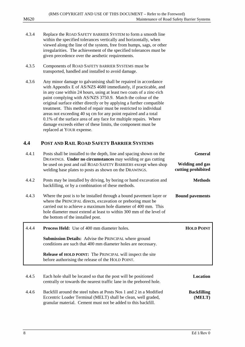
4.3.4 Replace the ROAD SAFETY BARRIER SYSTEM to form a smooth line within the specified tolerances vertically and horizontally, when viewed along the line of the system, free from humps, sags, or other irregularities. The achievement of the specified tolerances must be given precedence over the aesthetic requirements.
4.3.5 Components of ROAD SAFETY BARRIER SYSTEMS must be transported, handled and installed to avoid damage.
4.3.6 Any minor damage to galvanising shall be repaired in accordance with Appendix E of AS/NZS 4680 immediately, if practicable, and in any case within 24 hours, using at least two coats of a zinc-rich paint complying with AS/NZS 3750.9. Match the colour of the original surface either directly or by applying a further compatible treatment. This method of repair must be restricted to individual areas not exceeding 40 sq cm for any point repaired and a total 0.1% of the surface area of any face for multiple repairs. Where damage exceeds either of these limits, the component must be replaced at YOUR expense.
4.4 POST AND RAIL ROAD SAFETY BARRIER SYSTEMS
4.4.1 Posts shall be installed to the depth, line and spacing shown on the DRAWINGS. Under no circumstances may welding or gas cutting be used on post and rail ROAD SAFETY BARRIERS except when shop welding base plates to posts as shown on the DRAWINGS.
General
Welding and gas cutting prohibited
4.4.2 Posts may be installed by driving, by boring or hand excavation and backfilling, or by a combination of these methods.
Methods
4.4.3 Where the post is to be installed through a bound pavement layer or where the PRINCIPAL directs, excavation or preboring must be carried out to achieve a maximum hole diameter of 400 mm. This hole diameter must extend at least to within 300 mm of the level of the bottom of the installed post.
Bound pavements
4.4.4 Process Held: Use of 400 mm diameter holes.
Submission Details: Advise the PRINCIPAL where ground conditions are such that 400 mm diameter holes are necessary.
Release of HOLD POINT: The PRINCIPAL will inspect the site before authorising the release of the HOLD POINT.
HOLD POINT
4.4.5 Each hole shall be located so that the post will be positioned
centrally or towards the nearest traffic lane in the prebored hole. Location
4.4.6 Backfill around the steel tubes at Posts Nos 1 and 2 in a Modified Eccentric Loader Terminal (MELT) shall be clean, well graded, granular material. Cement must not be added to this backfill.
Backfilling (MELT)
8 Ed 1/Rev 0
(RMS COPYRIGHT AND USE OF THIS DOCUMENT – Refer to the Foreword) Maintenance of Road Safety Barrier Systems M620
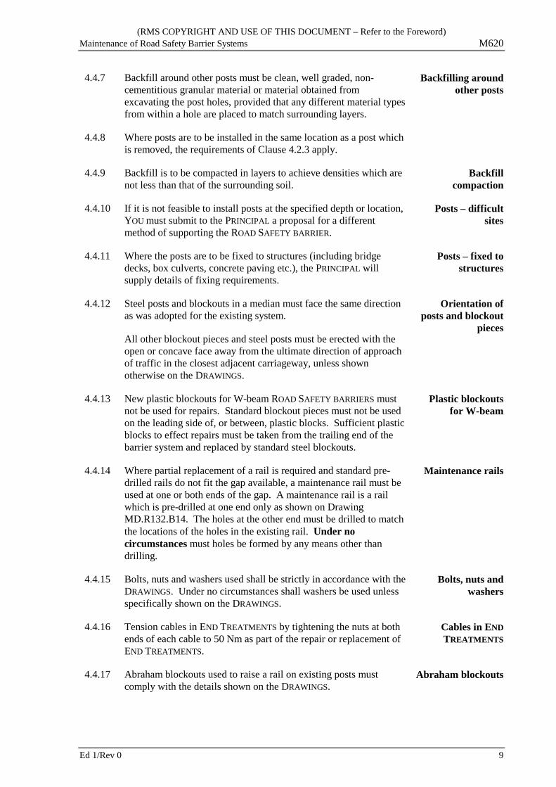
4.4.7 Backfill around other posts must be clean, well graded, non-cementitious granular material or material obtained from excavating the post holes, provided that any different material types from within a hole are placed to match surrounding layers.
Backfilling around other posts
4.4.8 Where posts are to be installed in the same location as a post which is removed, the requirements of Clause 4.2.3 apply.
4.4.9 Backfill is to be compacted in layers to achieve densities which are not less than that of the surrounding soil.
Backfill compaction
4.4.10 If it is not feasible to install posts at the specified depth or location, YOU must submit to the PRINCIPAL a proposal for a different method of supporting the ROAD SAFETY BARRIER.
Posts – difficult sites
4.4.11 Where the posts are to be fixed to structures (including bridge decks, box culverts, concrete paving etc.), the PRINCIPAL will supply details of fixing requirements.
Posts – fixed to structures
4.4.12 Steel posts and blockouts in a median must face the same direction as was adopted for the existing system.
All other blockout pieces and steel posts must be erected with the open or concave face away from the ultimate direction of approach of traffic in the closest adjacent carriageway, unless shown otherwise on the DRAWINGS.
Orientation of posts and blockout
pieces
4.4.13 New plastic blockouts for W-beam ROAD SAFETY BARRIERS must not be used for repairs. Standard blockout pieces must not be used on the leading side of, or between, plastic blocks. Sufficient plastic blocks to effect repairs must be taken from the trailing end of the barrier system and replaced by standard steel blockouts.
Plastic blockouts for W-beam
4.4.14 Where partial replacement of a rail is required and standard pre-drilled rails do not fit the gap available, a maintenance rail must be used at one or both ends of the gap. A maintenance rail is a rail which is pre-drilled at one end only as shown on Drawing MD.R132.B14. The holes at the other end must be drilled to match the locations of the holes in the existing rail. Under no circumstances must holes be formed by any means other than drilling.
Maintenance rails
4.4.15 Bolts, nuts and washers used shall be strictly in accordance with the DRAWINGS. Under no circumstances shall washers be used unless specifically shown on the DRAWINGS.
Bolts, nuts and washers
4.4.16 Tension cables in END TREATMENTS by tightening the nuts at both ends of each cable to 50 Nm as part of the repair or replacement of END TREATMENTS.
Cables in END TREATMENTS
4.4.17 Abraham blockouts used to raise a rail on existing posts must comply with the details shown on the DRAWINGS.
Abraham blockouts
Ed 1/Rev 0 9

(RMS COPYRIGHT AND USE OF THIS DOCUMENT – Refer to the Foreword) M620 Maintenance of Road Safety Barrier Systems
4.5 CONCRETE ROAD SAFETY BARRIER SYSTEMS
4.5.1 Concrete barriers must be dowelled or keyed to the underlying surface in accordance with the DRAWINGS or the PRINCIPAL’S instructions.
Concrete
4.5.2 Existing insitu concrete at the ends of a section to be replaced must be cut back to form a joint normal to the line of the barrier and for a sufficient distance to allow reinforcement to lap by not less than the length specified in Clause 4.5.4.
Ends of a section to be replaced
4.5.3 Prior to replacing any part of a concrete ROAD SAFETY BARRIER SYSTEM on a concrete surface:
Preparatory work for a concrete
surface
.1 Where fixed forms or slipforming is used:
(i) Fill each joint in the concrete surface on the line of the barrier with a bead of silicone sealant, extending the full width and a minimum of 100 mm outside both edges of the base of the ROAD SAFETY BARRIER, and forming a convex surface wholly proud of the plane of the pavement;
Fixed forms or slipforming used
(ii) After filling each joint as in i) above, debond the concrete surface on the line of the barrier by applying a uniform cover of curing compound at the rate of 0.3 l/sq m, extending the full width and a minimum of 100 mm outside both edges of the base of the ROAD SAFETY BARRIER; and
.2 Where precast ROAD SAFETY BARRIER segments (except segments of a proprietary ROAD SAFETY BARRIER SYSTEM) are used:
(i) Debond the concrete surface under the base of the barrier;
(ii) Construct a (nominal) 15 mm cement mortar pad beneath and for the full width and length of the barrier.
Precast ROAD SAFETY BARRIER
segments used
Proprietary concrete ROAD SAFETY BARRIER SYSTEMS components must be replaced in accordance with the ACCEPTANCE DOCUMENT or the manufacturer’s recommendations, as applicable.
10 Ed 1/Rev 0

(RMS COPYRIGHT AND USE OF THIS DOCUMENT – Refer to the Foreword) Maintenance of Road Safety Barrier Systems M620
4.5.4 Reinforcing steel must conform to the details shown on the DRAWINGS. In areas of steel congestion, do not splice at locations other than those shown on the DRAWINGS. Unless shown otherwise or calculated in accordance with AS 3600, the length of lapped splices must be as follows:
(a) Deformed bar, grade 500N:
20 mm Φ or less 40 bar diameters
24 mm Φ 1100 mm
28 mm Φ and over AS 3600
(b) Plain bars and hard-drawn wire: 50 bar diameters
(c) Reinforcing fabric: the two outermost transverse wires of one sheet of fabric must overlap the two outermost transverse wires of the sheet being lapped
(d) 7-wire prestressing strand: 90 strand diameters.
Welding must comply with AS 1554.3.
The minimum cover of any steel bar, wire or fabric reinforcement to the nearest concrete surface is 50 mm unless shown otherwise on the DRAWINGS.
Support reinforcement using either concrete or plastic chairs. Do not use wire chairs with or without plastic tips, bricks or pieces of timber or coarse aggregate to support reinforcement.
Reinforcement
4.5.5 The materials, design, fabrication, erection and stripping of formwork, must comply with the relevant requirements of AS 3610 and this SPECIFICATION. Construct joints in formwork to prevent loss of mortar.
Before placing reinforced concrete in an earth excavation:
(a) place a 50 mm thick layer of unreinforced concrete on the floor of the excavation, and
(b) erect formwork so that fresh concrete is not placed directly against the sides of the excavation,
unless shown otherwise on the DRAWINGS or approved otherwise by the PRINCIPAL.
Formwork
Ed 1/Rev 0 11

(RMS COPYRIGHT AND USE OF THIS DOCUMENT – Refer to the Foreword) M620 Maintenance of Road Safety Barrier Systems
4.5.6 Handle, place and finish concrete so as to:
(a) limit segregation or loss of materials;
(b) limit premature stiffening;
(c) produce a dense homogeneous product which is monolithic between joints and edges;
(d) expel entrapped air and closely surround all reinforcement and embedments; and
(e) provide the specified thickness and surface finish.
Do not place concrete either during rain or when the air temperature in the shade is below 5°C or above 38°C.
Finish unformed concrete surfaces:
(a) to achieve the specified:
(i) dimensions and grade;
(ii) cover from the surface to reinforcement and embedments;
(iii) texture of the surface; and
(b) to avoid plastic or drying shrinkage cracks.
Unless specified or shown otherwise on the Drawings, do not finish unformed surfaces with a wood float.
Handling, placing and finishing
4.5.7 For concrete placed in-situ (fixed forms or slipforming), saw or form movement joints to control cracking. Movement joints must be straight, square to the line of the barrier, between 45 to 55 mm deep, and spaced at intervals of not more than 4.5 m along the barrier.
Joints in concrete placed in-situ
4.5.8 Where sawing is used to control cracks, it must be done before uncontrolled cracking begins, and in any case, within 12 hours after placing the concrete.
Saw cutting
4.5.9 Where a concrete ROAD SAFETY BARRIER is cast or slipformed adjacent to or on top of a concrete pavement base layer, the same type of movement, construction and isolation joints in the concrete pavement base must be made in the ROAD SAFETY BARRIER and located to form a continuous joint through both structures.
Matching joints in barrier with joints
in underlying concrete pavement
4.5.10 Movement joints must be constructed where shown on the DRAWINGS. Movement joints must be straight, square to the line of the barrier, and between 6 to 8 mm wide. Movement joints must be filled with a preformed joint filler complying with RMS 3204.
Expansion joints
12 Ed 1/Rev 0
(RMS COPYRIGHT AND USE OF THIS DOCUMENT – Refer to the Foreword) Maintenance of Road Safety Barrier Systems M620
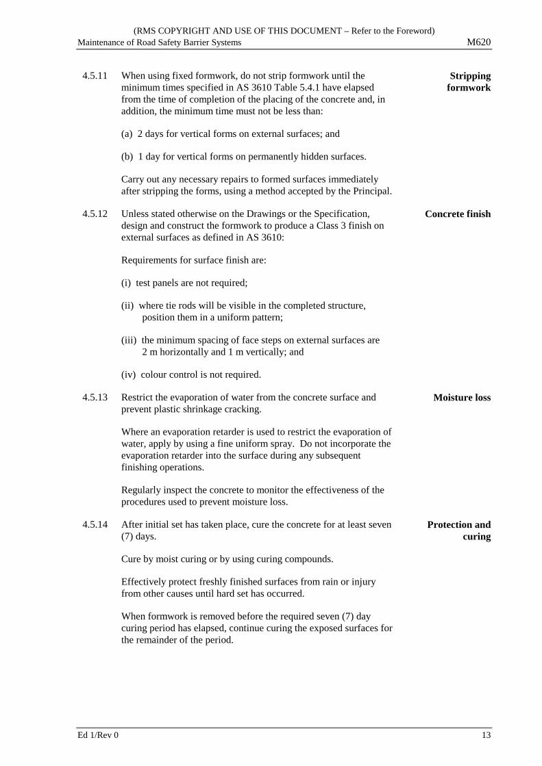
4.5.11 When using fixed formwork, do not strip formwork until the minimum times specified in AS 3610 Table 5.4.1 have elapsed from the time of completion of the placing of the concrete and, in addition, the minimum time must not be less than:
(a) 2 days for vertical forms on external surfaces; and
(b) 1 day for vertical forms on permanently hidden surfaces.
Carry out any necessary repairs to formed surfaces immediately after stripping the forms, using a method accepted by the Principal.
Stripping formwork
4.5.12 Unless stated otherwise on the Drawings or the Specification, design and construct the formwork to produce a Class 3 finish on external surfaces as defined in AS 3610:
Requirements for surface finish are:
(i) test panels are not required;
(ii) where tie rods will be visible in the completed structure, position them in a uniform pattern;
(iii) the minimum spacing of face steps on external surfaces are 2 m horizontally and 1 m vertically; and
(iv) colour control is not required.
Concrete finish
4.5.13 Restrict the evaporation of water from the concrete surface and prevent plastic shrinkage cracking.
Where an evaporation retarder is used to restrict the evaporation of water, apply by using a fine uniform spray. Do not incorporate the evaporation retarder into the surface during any subsequent finishing operations.
Regularly inspect the concrete to monitor the effectiveness of the procedures used to prevent moisture loss.
Moisture loss
4.5.14 After initial set has taken place, cure the concrete for at least seven (7) days.
Cure by moist curing or by using curing compounds.
Effectively protect freshly finished surfaces from rain or injury from other causes until hard set has occurred.
When formwork is removed before the required seven (7) day curing period has elapsed, continue curing the exposed surfaces for the remainder of the period.
Protection and curing
Ed 1/Rev 0 13

(RMS COPYRIGHT AND USE OF THIS DOCUMENT – Refer to the Foreword) M620 Maintenance of Road Safety Barrier Systems
Immediately after the concrete has taken its initial set, spray all exposed surfaces with water and keep the concrete continually wet for at least seven (7) days. The water used must be free from ingredients harmful to concrete.
Moist curing
Curing compounds must be:
(a) a hydrocarbon resin compound complying with AS 3799 Type 1-D, or
(b) a wax emulsion complying with AS 3799 Type 1.
Apply the curing compound at the rate specified by the manufacturer, or at the rate of 0.20 litre/m2, whichever is the greater. Apply the curing compound to all exposed surfaces to give a uniform cover. Apply two coats when necessary to ensure complete and uniform coverage. The time between the first and second coat must be in accordance with the manufacturer’s recommendation, or on the basis of a trial application.
Apply curing compound to unformed surfaces immediately after the surface is firm and free of bleed water, and to formed surfaces within 30 minutes of removal of formwork. Apply to slipformed surfaces as soon as possible after forming. After stripping, and before applying the curing compound, moisten formed surfaces by light spraying until the surface will not readily absorb more water.
Use of a curing compound
Care must be taken to ensure that the curing compound is thoroughly mixed during application. Where a sprayer is used, it must incorporate a device for continuous agitation and mixing of the compound in its container during spraying.
Check the application rate by calculating the application rate from the total measured surface area covered and by another method selected to indicate uniformity of cover. For spray application to horizontal, surfaces uniformity may be demonstrated by calculating the amount of curing compound falling on felt mats, each approximately 0.25 m2 in area, placed on the concrete surface. On removal of the felt mats, apply curing compound to the area they covered.
Keep equipment and materials for curing on hand at all times during concrete placing and for a minimum of 7 days thereafter.
Take care during application to ensure that curing compound is not deposited on adjacent surfaces and does not drift away from the concrete.
Maintain the curing membrane intact until at least seven (7) days have elapsed after placing the concrete. During this period, repair any damage to the curing membrane by further application of curing compound to the affected areas within 30 minutes of the damage occurring.
14 Ed 1/Rev 0

(RMS COPYRIGHT AND USE OF THIS DOCUMENT – Refer to the Foreword) Maintenance of Road Safety Barrier Systems M620
4.6 STEEL WIRE ROPE ROAD SAFETY BARRIER SYSTEMS
Steel wire rope ROAD SAFETY BARRIER SYSTEMS must be repaired and components replaced in accordance with the ACCEPTANCE DOCUMENT or the manufacturer’s recommendations, as applicable..
4.7 END TREATMENTS AND TRANSITIONS
4.7.1 Before replacing any END TREATMENT or TRANSITION, the site layout and surface preparation must comply with the requirements shown on the DRAWINGS, described in the ACCEPTANCE DOCUMENT or stated in the manufacturer’s recommendations, whichever is applicable.
Surface preparation
4.7.2 END TREATMENTS for post and rail ROAD SAFETY BARRIER SYSTEMS must be replaced in accordance with the DRAWINGS and the requirements of Clause 4.4.
Post and rail barriers
4.7.3 END TREATMENTS for concrete ROAD SAFETY BARRIER SYSTEMS must be replaced in accordance with the DRAWINGS and the requirements of Clause 4.5.
Concrete barriers
4.7.4 Proprietary ROAD SAFETY BARRIER END TREATMENT components must be replaced in accordance with the ACCEPTANCE DOCUMENT or the manufacturer’s recommendations, as applicable..
Proprietary systems
4.7.5 Replace TRANSITIONS in accordance with the DRAWINGS and the ACCEPTANCE DOCUMENT or the manufacturer’s recommendations, as applicable. Where the replacement of a TRANSITION requires repair or modification of any part of a bridge refer the matter to the PRINCIPAL for direction.
TRANSITIONS
4.8 DELINEATION
4.8.1 Mount DELINEATION UNITS on ROAD SAFETY BARRIER SYSTEMS at locations and spacings to match the existing DELINEATION UNITS unless directed otherwise by the PRINCIPAL.
Match existing
4.8.2 Arrange DELINEATION UNITS so that drivers approaching from either direction will see only:
.1 Red retro-reflectors on their left.
Arrangement of DELINEATORS
.2 White retro-reflectors on their right on two-way carriageways.
.3 Yellow retro-reflectors on their right on one-way carriageways and medians separating traffic in opposing directions.
For post and rail ROAD SAFETY BARRIER SYSTEMS, replacement DELINEATION UNITS must be as shown on Drawing MD.R132.E01.
Ed 1/Rev 0 15
(RMS COPYRIGHT AND USE OF THIS DOCUMENT – Refer to the Foreword) M620 Maintenance of Road Safety Barrier Systems
5 CONFORMITY
5.1 GENERAL
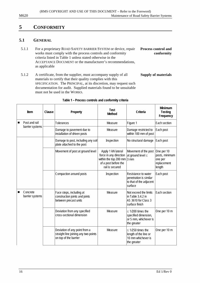
5.1.1 For a proprietary ROAD SAFETY BARRIER SYSTEM or device, repair works must comply with the process controls and conformity criteria listed in Table 1 unless stated otherwise in the ACCEPTANCE DOCUMENT or the manufacturer’s recommendations, as applicable
Process control and conformity
5.1.2 A certificate, from the supplier, must accompany supply of all materials to certify that their quality complies with this SPECIFICATION. The PRINCIPAL, at its discretion, may request such documentation for audit. Supplied materials found to be unsuitable must not be used in the WORKS.
Supply of materials
Table 1 – Process controls and conformity criteria
Item Clause Property Test Method Criteria
Minimum Testing
Frequency
Post and rail barrier systems
Tolerances Measure Figure 1 Each section
Damage to pavement due to installation of driven posts
Measure Damage restricted to within 100 mm of post
Each post
Damage to post, including any soil plate attached to the post
Inspection No structural damage Each post
Movement of post at ground level Apply 1 kN lateral force in any direction
within the top 200 mm of a post before the
rail is secured
Movement of the post at ground level ≤ 3 mm
One per 10 posts, minimum one per replacement length
Compaction around posts Inspection Resistance to water penetration is similar to that of the adjacent surface
Each post
Concrete barrier systems
Face steps, including at construction joints and joints between precast units
Measure Not exceed the limits in Table 3.4.2 in AS 3610 for Class 3 surface finish
Each section
Deviation from any specified cross-sectional dimension
Measure ≤ 1/200 times the specified dimension, or 5 mm, whichever is the greater
One per 10 m
Deviation of any point from a straight line joining any two points on top of the barrier
Measure ≤ 1/250 times the length of the line or 10 mm whichever is the greater
One per 10 m
16 Ed 1/Rev 0

(RMS COPYRIGHT AND USE OF THIS DOCUMENT – Refer to the Foreword) Maintenance of Road Safety Barrier Systems M620
Item Clause Property Test Method Criteria
Minimum Testing
Frequency
Surface undulations Measure Not exceed the limits in Table 3.4.2 in AS 3610 for Class 3 surface finish
One per 10 m
4.5.9 Any offset between the line of an existing joint in a concrete pavement base layer and the line of the corresponding joint in the barrier
Measure ≤ 15 mm at the bottom of the barrier.
Each pavement joint
Deviation of a transverse joint, comprising a series of contiguous straight lines on the surfaces of the barrier.
Measure ≤ 10 mm Each joint
4.5.8 Sawing to control cracks Measure Within 12 hours of placing concrete
Each saw cut
Straightness of expansion and movement joints
Measure Within ± 50 of square Each joint
4.5.7 Depth of movement joints Measure Between 45 to 55 mm Each joint
4.5.7 Spacing of movement joints Measure ≤ 4.5 m Each section
4.5.10 Width of movement joints Measure Between 6 to 8 mm Each joint
Wire rope barrier systems
Tolerances Measure ACCEPTANCE DOCUMENT or manufacturer’s recommendation, as applicable
Each section
END TREATMENTS and TRANSITIONS
Tolerances for post and rail and concrete ROAD SAFETY BARRIER END TREATMENTS and TRANSITIONS
Measure As per post and rail and concrete barriers in Table 1
Each section
Tolerances for proprietary ROAD SAFETY BARRIER END TREATMENTS and TRANSITIONS
Measure ACCEPTANCE DOCUMENT
Each section
Ed 1/Rev 0 17
(RMS COPYRIGHT AND USE OF THIS DOCUMENT – Refer to the Foreword) M620 Maintenance of Road Safety Barrier Systems
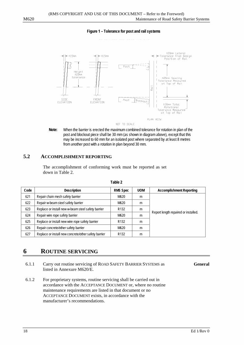
Figure 1 – Tolerance for post and rail systems
Note: When the barrier is erected the maximum combined tolerance for rotation in plan of the
post and blockout piece shall be 30 mm (as shown in diagram above), except that this may be increased to 60 mm for an isolated post where separated by at least 8 metres from another post with a rotation in plan beyond 30 mm.
5.2 ACCOMPLISHMENT REPORTING
The accomplishment of conforming work must be reported as set down in Table 2.
Table 2
Code Description RMS Spec UOM Accomplishment Reporting 621 Repair chain mesh safety barrier M620 m
Report length repaired or installed.
622 Repair w-beam steel safety barrier M620 m 623 Replace or install new w-beam steel safety barrier R132 m 624 Repair wire rope safety barrier M620 m 625 Replace or install new wire rope safety barrier R132 m 626 Repair concrete/other safety barrier M620 m 627 Replace or install new concrete/other safety barrier R132 m
6 ROUTINE SERVICING
6.1.1 Carry out routine servicing of ROAD SAFETY BARRIER SYSTEMS as listed in Annexure M620/E.
General
6.1.2 For proprietary systems, routine servicing shall be carried out in accordance with the ACCEPTANCE DOCUMENT or, where no routine maintenance requirements are listed in that document or no ACCEPTANCE DOCUMENT exists, in accordance with the manufacturer’s recommendations.
18 Ed 1/Rev 0

(RMS COPYRIGHT AND USE OF THIS DOCUMENT – Refer to the Foreword) Maintenance of Road Safety Barrier Systems M620
ANNEXURE M620/A – DETAILS OF WORK
A1 LOCATION AND DETAILS OF WORK
Road No.
Chainage (L/R) Item Activity Quantity Drawing
Reference (i)
Note: (i)
A2 PRINCIPAL'S ASSESSMENT OF THE CONDITION OF EXISTING BARRIERS
Road No.
Chainage (L/R) Item Assessed condition
Note: (i)
Ed 1/Rev 0 19
(RMS COPYRIGHT AND USE OF THIS DOCUMENT – Refer to the Foreword) M620 Maintenance of Road Safety Barrier Systems
A3 REPLACEMENT REQUIREMENTS
Road No.
Chainage (L/R) Item Requirements
Note: (i)
20 Ed 1/Rev 0

(RMS COPYRIGHT AND USE OF THIS DOCUMENT – Refer to the Foreword) Maintenance of Road Safety Barrier Systems M620
ANNEXURE M620/B – MEASUREMENT AND PAYMENT
B1 GENERAL
B1.1 Pay items are identified in Annexure M620/B2. Pay Items to be used
B1.2 The price(s) of pay items with a quantity of work in the schedule must be costed with due allowance for all costs of the ACTIVITY.
Any pay item with a quantity of work that is not priced is understood to be included in other priced pay items.
Prices
B1.3 Any overheads must be distributed between pay items. Overheads
B1.4 Pay items with a quantity of work specified must not be tendered as a LUMP SUM PRICE.
No Lump Sum
B1.5 You are not paid for events that include:
.1 Removing and replacing nonconforming material with conforming material.
.2 Rework required to achieve conformity.
No payment
Ed 1/Rev 0 21
(RMS COPYRIGHT AND USE OF THIS DOCUMENT – Refer to the Foreword) M620 Maintenance of Road Safety Barrier Systems
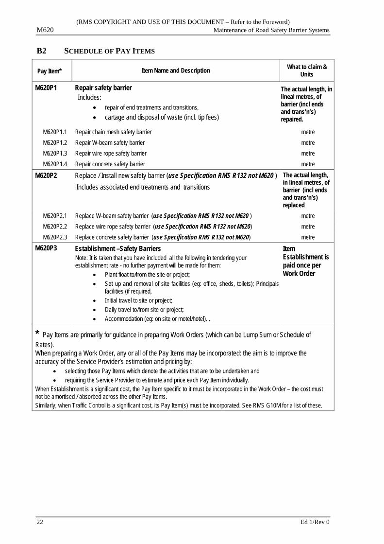
B2 SCHEDULE OF PAY ITEMS
Pay Item* Item Name and Description What to claim & Units
M620P1 Repair safety barrier Includes:
• repair of end treatments and transitions, • cartage and disposal of waste (incl. tip fees)
The actual length, in lineal metres, of barrier (incl ends and trans’n’s) repaired.
M620P1.1 Repair chain mesh safety barrier metre M620P1.2 Repair W-beam safety barrier metre M620P1.3 Repair wire rope safety barrier metre M620P1.4 Repair concrete safety barrier metre
M620P2 Replace / Install new safety barrier (use Specification RMS R132 not M620 ) Includes associated end treatments and transitions
The actual length, in lineal metres, of barrier (incl ends and trans’n’s) replaced
M620P2.1 Replace W-beam safety barrier (use Specification RMS R132 not M620 ) metre M620P2.2 Replace wire rope safety barrier (use Specification RMS R132 not M620) metre M620P2.3 Replace concrete safety barrier (use Specification RMS R132 not M620) metre
M620P3 Establishment –Safety Barriers Note: It is taken that you have included all the following in tendering your establishment rate - no further payment will be made for them:
• Plant float to/from the site or project; • Set up and removal of site facilities (eg: office, sheds, toilets); Principals
facilities (if required, • Initial travel to site or project; • Daily travel to/from site or project; • Accommodation (eg: on site or motel/hotel). .
Item Establishment is paid once per Work Order
* Pay Items are primarily for guidance in preparing Work Orders (which can be Lump Sum or Schedule of Rates). When preparing a Work Order, any or all of the Pay Items may be incorporated: the aim is to improve the accuracy of the Service Provider’s estimation and pricing by:
• selecting those Pay Items which denote the activities that are to be undertaken and • requiring the Service Provider to estimate and price each Pay Item individually.
When Establishment is a significant cost, the Pay Item specific to it must be incorporated in the Work Order – the cost must not be amortised / absorbed across the other Pay Items. Similarly, when Traffic Control is a significant cost, its Pay Item(s) must be incorporated. See RMS G10M for a list of these.
22 Ed 1/Rev 0
(RMS COPYRIGHT AND USE OF THIS DOCUMENT – Refer to the Foreword) Maintenance of Road Safety Barrier Systems M620
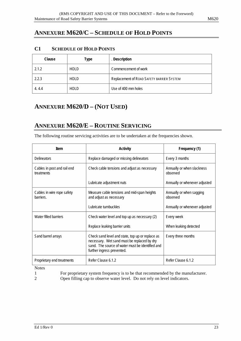
ANNEXURE M620/C – SCHEDULE OF HOLD POINTS
C1 SCHEDULE OF HOLD POINTS
Clause Type . Description
2.1.2 HOLD Commencement of work
2.2.3 HOLD Replacement of ROAD SAFETY BARRIER SYSTEM
4. 4.4 HOLD Use of 400 mm holes
ANNEXURE M620/D – (NOT USED)
ANNEXURE M620/E – ROUTINE SERVICING The following routine servicing activities are to be undertaken at the frequencies shown.
Item Activity Frequency (1)
Delineators Replace damaged or missing delineators Every 3 months
Cables in post and rail end treatments
Check cable tensions and adjust as necessary
Lubricate adjustment nuts
Annually or when slackness observed
Annually or whenever adjusted
Cables in wire rope safety barriers.
Measure cable tensions and mid-span heights and adjust as necessary
Lubricate turnbuckles
Annually or when sagging observed
Annually or whenever adjusted
Water filled barriers Check water level and top up as necessary (2)
Replace leaking barrier units
Every week
When leaking detected
Sand barrel arrays Check sand level and state, top up or replace as necessary. Wet sand must be replaced by dry sand. The source of water must be identified and further ingress prevented.
Every three months
Proprietary end treatments Refer Clause 6.1.2 Refer Clause 6.1.2
Notes 1 For proprietary system frequency is to be that recommended by the manufacturer. 2 Open filling cap to observe water level. Do not rely on level indicators.
Ed 1/Rev 0 23
(RMS COPYRIGHT AND USE OF THIS DOCUMENT – Refer to the Foreword) M620 Maintenance of Road Safety Barrier Systems
ANNEXURES M620/F TO M620/L – (NOT USED)
ANNEXURE M620/M – REFERENCED DOCUMENTS AND DEFINITIONS
M1 ABBREVIATIONS
M1.1 Australian Standards
AS 1231 Aluminium and aluminium alloys – Anodic oxidation coatings
AS 1554.3 Structural steel welding Part 3: Welding of reinforcing steel
AS/NZS 1594 Hot rolled steel flat products
AS 1604.1 Specification for preservative treatment - Part 1: Sawn and round timber
AS 1734 Aluminium and aluminium alloys – Flat sheet, coiled sheet and plate
AS 1906.1 Retroreflective materials
AS 1906.2 Retroreflective devices (non-pavement application)
AS 3600 Concrete structures
AS 3610 Formwork for concrete
AS/NZS 3750.9 Paints for steel structures – Part 9: Organic zinc-rich primer
AS 3799 Liquid membrane-forming curing compounds for concrete
AS/NZS 3845 Road safety barrier systems
AS/NZS 4671 Steel reinforcing materials
AS/NZS 4672.1 Steel prestressing materials Part 1: General requirements
AS/NZS 4680 Hot-dipped galvanised zinc coatings on fabricated ferrous articles
SA 5605 Guide to the safe use of preservative-treated timber
M1.2 RMS Specifications and Documents
RMS G1 Contract specific requirements
RMS G10M Traffic Management
RMS G22 Work Health and Safety (construction and Maintenance Works)
RMS G71 Construction Surveys
RMS Q Quality Management System
RMS M1 Maintenance Performance Standards
RMS 3201 Concrete Supply for Maintenance
24 Ed 1/Rev 0

(RMS COPYRIGHT AND USE OF THIS DOCUMENT – Refer to the Foreword) Maintenance of Road Safety Barrier Systems M620
RMS 3204 Preformed Joint Fillers for Concrete Road Pavements and Structures
RMS B115 Precast Concrete Members (Not Pretensioned)
RMS T166 Determination of Relative Compaction
RMS RDG Road Design Guide
M2 DEFINED TERMS
ACCEPTANCE DOCUMENT
The document prepared by RMS which describes the properties and conditions of acceptance of a ROAD SAFETY BARRIER system accepted by RMS using a risk assessment process.
CLEAR ZONE The area that begins at the outer edge of the lane and extends on both sides for a set distance, which is available for use by errant vehicles. For two-way traffic the CLEAR ZONE on the right hand side is measured from the lane line which separates the opposing traffic. See RMS RDG Sections 3.6 and 6.
DELINEATION/ DELINEATION UNIT
Delineation refers to treatments which enhance the definition of the roadway operating area. In the context of this SPECIFICATION A DELINEATION UNIT IS either: a retro-reflector fixed to a mounting plate attached to a ROAD SAFETY BARRIER, or, a guide post or, a unit attached to, or placed immediately in front of, an END TREATMENT.
DEPARTURE END TREATMENT
An END TREATMENT for a ROAD SAFETY BARRIERof a type which is used only at the departure end with respect to the direction of flow of traffic.
DEVICE A generic term used to refer to a ROAD SAFETY BARRIER, an END TREATMENT OR a TRANSITION. In the context of this SPECIFICATION, a device is usually part of a ROAD SAFETY BARRIER SYSTEM.
The term is also used to describe a type of retroreflector. Refer to AS 1906.2 for further information.
DRAWING A drawing or sketch issued as part of the CONTRACT documentation, by the PRINCIPAL for use in connection with the CONTRACT or included in an ACCEPTANCE DOCUMENT.
END TREATMENT (Also called a TERMINAL). A device to protect vehicle occupants from injury in an impact with the end of a ROAD SAFETY BARRIER. END TREATMENTS may be LEADING END TREATMENTS or DEPARTURE END TREATMENTS.
LEADING END TREATMENT
An END TREATMENT at the end of a ROAD SAFETY BARRIER SYSTEM which faces oncoming traffic.
NESTED RAILS Two steel rails erected together (one inside the other) to increase stiffness. Nested rails share splice bolts.
ROAD SAFETY BARRIER That part of a ROAD SAFETY BARRIER SYSTEM other than END TREATMENTS and TRANSITIONS.
ROAD SAFETY BARRIER SYSTEM
A longitudinal structure whose prime purpose is to restrain and/or redirect in a controlled manner vehicles which are out of control. A ROAD SAFETY BARRIER SYSTEM includes one or more ROAD SAFETY BARRIERS with associated END TREATMENTS and TRANSITIONS.
TERMINAL See END TREATMENT.
Ed 1/Rev 0 25

(RMS COPYRIGHT AND USE OF THIS DOCUMENT – Refer to the Foreword) M620 Maintenance of Road Safety Barrier Systems
TRANSITION A connecting device to provide effective continuity of the protection offered by a ROAD SAFETY BARRIER between ROAD SAFETY BARRIERS of different properties or dimensions. The part of a ROAD SAFETY BARRIER SYSTEM with varying properties such as stiffness and dimensions, between and linking ROAD SAFETY BARRIERS with different properties or dimensions. A TRANSITION may also be a link, or connection of A ROAD SAFETY BARRIER to a fixture.
M.3 MODEL DRAWINGS
M.3.1 Material details
MD.R132.A01 W Beam and Thrie Beam Safety Barriers - Post and Blockout Components
MD.R132.A02 Modified Thrie Beam Safety Barrier - Notched Blockout
MD.R132.A03 Modified Eccentric Loader Terminal (MELT) - Post, Tube and Yoke Details
MD.R132.A04 W Beam and Thrie Beam Safety Barriers - Post on Base Plate
MD.R132.A05 W Beam and Thrie Beam Safety Barriers - Post on Slip Base Plate
MD.R132.A06 W Beam Safety Barrier - Abraham Blockout for Raising Rail Height on Exist. Post
MD.R132.B01 W Beam Rail and Stiffening Piece Connection
MD.R132.B02 Thrie Beam Rail (2.7BMT & 3.5BMT) and Stiffening Piece Connection
MD.R132.B03 W Beam and Thrie Beam Safety Barriers - Terminal Connectors
MD.R132.B04 W Beam and Thrie Beam Safety Barriers - W Beam to Thrie Beam Transition
MD.R132.B05 W Beam Nesting Rail and Half Length Rail
MD.R132.B06 Half Length Rail
MD.R132.B07 Thrie Beam - 2.7BMT Nesting Rail and 3.5BMT Rail for Transition to Rigid Barrier
MD.R132.B08 W Beam Rail - Terminal Component - Anchor Plate
MD.R132.B09 MELT and TT Terminals - W Beam Rail Detail of Terminal Rails
MD.R132.B10 Modified Eccentric Loader Terminal (MELT) - Diaphragm Plate Details
MD.R132.B11 Modified Eccentric Loader Terminal and Trailing Terminal Buffered End Section Details
MD.R132.B14 W Beam Rail - Maintenance Rail
MD.R132.C01 Modified Eccentric Loader Terminal and Trailing Terminal Cable Assembly and Fasteners
MD.R132.C02 W Beam and Thrie Beam Rail - Fastener Components M16 Bolts and Nuts - Rail
MD.R132.C03 W Beam and Thrie Beam Rail - Fastener Components Hexagon Head Bolts and Nuts
MD.R132.C04 W Beam and Thrie Beam – Posts Base Plates and Slip Base Plates, Hexagon Head Bolts and Nuts
MD.R132.E01 W Beam and Thrie Beam Safety Barriers - Delineation Unit
M.3.2 Installation details
MD.R132.F01 AASHTO G4 W Beam Assembly
26 Ed 1/Rev 0

(RMS COPYRIGHT AND USE OF THIS DOCUMENT – Refer to the Foreword) Maintenance of Road Safety Barrier Systems M620
MD.R132.F02 Thrie Beam Assembly using Standard Blockout
MD.R132.F03 Modified Thrie Beam Assembly using Notched Blockout
MD.R132.F04 AASHTO G4 W Beam Nested Rail Assembly
MD.R132.F05 Thrie Beam Nested Rail Assembly
MD.R132.F06 W-Beam and Thrie Beam, Post Installation - Hard Ground and Terminals
MD.R132.G01 Modified Eccentric Loader Terminal (MELT) - General Arrangement
MD.R132.G02 Modified Eccentric Loader Terminal (MELT) - Buffered End & Anchorage Detail
MD.R132.G03 Trailing Terminal (TT) General Arrangement & Post and Anchorage Detail
MD.R132.H01 W Beam Connection to Type ‘F’ Barrier or Parapet on Concrete Bridges
MD.R132.H02 Thrie Beam Connection to Type ‘F’ Barrier or Parapet on Concrete Bridges
LAST PAGE
Ed 1/Rev 0 27