m42 x 2 • iso 7789 = 350 bar
TRANSCRIPT

Proportional flow control valves
Wandfluh AG Tel. +41 33 672 72 72 E-mail: [email protected] Illustrations not obligatory Data sheet no.Postfach Fax +41 33 672 72 12 Internet: www.wandfluh.com Data subject to change 2.6-695E 1/3CH-3714 Frutigen Edition 15 08
Proportional 3-way flow control valveScrew-in cartridge• Direct operated, pressure compensated• Qmax = 200 l/min, pmax = 350 bar• QN max = 160 l/min
DESCRIPTIONDirect operated, pressure compensated pro-portional flow control valve as a screw-in cart-ridge with a thread M42 x 2 for cavity acc. to ISO 7789. The volume flow is adjusted by a Wandfluh proportional solenoid (VDE standard 0580). The cartridge body is made of steel. A special surface treatment guarantees a good protection against corrosion and wear as well as very good low-friction characteristics of the pressure compensating- and throttle spool. The solenoid coil is zinc- / nickel-coated.
FUNCTIONThe 3-way flow control valve serves for maintai-ning the speed of a consumer constant inde-pendent of the load. Superfluous pump output flow is fed into the return flow system in a cost saving manner, and as a result, prevents an overheating of the hydraulic system. The po-wer controlled, proportional solenoid running in oil acts directly on the throttle spool, which opens the throttle segments in the cartridge body. Proportional to the current demand of the proportional solenoid, the throttle aperture changes, and with this the volume flow. In case of a current-free solenoid, the throttle spool is held in closed position by a spring. For driving the valve, Wandfluh proportional amplifiers are available (see Register 1.13).
APPLICATIONProportional flow control valves are suitable for feed control systems, where the consumer flow has to be maintained constant with a changing load. The screw-in cartridge is suitable for in-stallation in control blocs.
GENERAL SPECIFICATIONSDescription 3-way proportional flow control valveConstruction Screw-in cartridge for cavity acc. to ISO 7789Operation Proportional solenoidMounting Screw-in thread M42 x 2Ambient temperature -20…70 °CMounting position anyFastening torque MD = 100 Nm for screw-in cartridge MD = 5 Nm for knurled nutWeight m = 2,34 kg Flow direction see symbol
SYMBOLSsimplified detailed
M42 x 2ISO 7789
TYPE CODE
Q D P PM42 - 160 - / W - #
Flow control valve
3-way
Proportional
Screw-in cartridge M42 x 2
Nominal volume flow rate QN 160 l/min
Nominal voltage UN 12 VDC G12 24 VDC G24 without coil X5
Slip-on coil Metal housing, round
Connection execution Connector socket EN 175301-803 / ISO 4400 D Connector socket AMP Junior-Timer J Connector Deutsch DT04-2P G
Sealing material NBR FKM (Viton) D1
Manual override Screwed sealing plug HB0 Manual emergency actuation HC8.5
Design-Index (Subject to change)
1 (P)
3 (A) 2 (T)
9088
s41
M42
x2
50 80 60 90 70
1
2
31
2
3
229138
1
3269 20
17
10
15

Proportional flow control valves
Wandfluh AG Tel. +41 33 672 72 72 E-mail: [email protected] Illustrations not obligatory Data sheet no.Postfach Fax +41 33 672 72 12 Internet: www.wandfluh.com Data subject to change 2.6-695E 2/3CH-3714 Frutigen Edition 15 08
ELECTRICAL SPECIFICATIONSConstruction Proportional solenoid, wet pin push type, pressure tight
Standard nominal voltage U = 12 VDC U = 24 VDCLimiting current IG = 2255 mA IG = 1105 mA
Relative duty factor 100 % ED / DF (see data sheet 1.1- 430)Protection class Connection versionacc. to EN 60 529 D: IP 65 J: IP66 G: IP 67 and 69KFor further electrical specifications see data sheet 1.1-191
HYDRAULIC SPECIFICATIONSFluid Mineral oil, other fluid on requestContamination efficiency ISO 4406:1999, class 18/16/13 (Requiredfiltrationgradeβ6…10 ≥ 75) see data sheet 1.0-50/2Viscosity range 12 mm2/s…320 mm2/sFluid temperature -20…+70 °CPeak pressure pmax = 350 barNominal volume flow rates QN = 160 l/minMax. volume flow Qmax =200l/min(1→2)Min. volume flow Qmin = 0,5 l/minHysteresis ٭%6≥ signalditheroptimalat٭
CHARACTERISTICS Oil viscosity ν= 30 mm2/sQ=f(I)Volumeflowsignalcharacteristics(p3 = 100 bar) Q = f (p) Volume flow pressure characteristics (I = IG)
Δp=f(Q)Pressuredrop-volumeflowcharacteristics1→2(I = 0 mA) Δp=f(Q)Pressuredrop-volumeflowcharacteristics1→3(I = IG)
0 10 20 30 40 50 60 70 80 90 100
K4098
Q [l/min]200
160
120
80
40
0I [%]
200
160
120
80
40
00 50 100 150 200 250 300 350 p [bar]
K4097
Q [l/min]
30
20
10
00 40 80 120 160 200 Q [l/min]
K4096
p [bar]
0 20 40 60 80 100 120 140 160 Q [l/min]
K4095
p [bar]10
8
6
4
2
0
Proportional flow control valves
Wandfluh AG Tel. +41 33 672 72 72 E-mail: [email protected] Illustrations not obligatory Data sheet no.Postfach Fax +41 33 672 72 12 Internet: www.wandfluh.com Data subject to change 2.6-695E 3/3CH-3714 Frutigen Edition 15 08
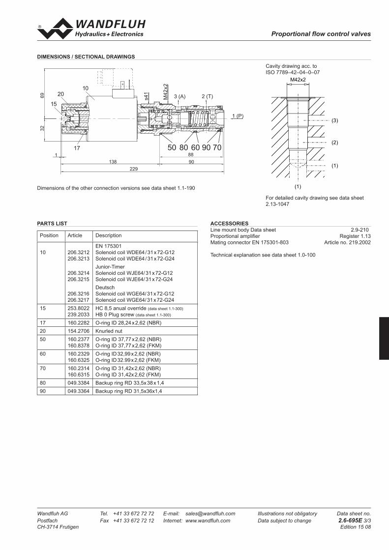
DIMENSIONS / SECTIONAL DRAWINGS
Cavity drawing acc. toISO 7789–42–04–0–07
For detailed cavity drawing see data sheet 2.13-1047
ACCESSORIESLine mount body Data sheet 2.9-210Proportional amplifier Register 1.13Mating connector EN 175301-803 Article no. 219.2002
Technical explanation see data sheet 1.0-100
PARTS LIST
Position Article Description
10 206.3212206.3213
206.3214206.3215
206.3216206.3217
EN 175301Solenoid coil WDE64 / 31 x 72-G12Solenoid coil WDE64 / 31 x 72-G24Junior-TimerSolenoid coil WJE64/ 31 x 72-G12Solenoid coil WJE64/ 31 x 72-G24DeutschSolenoid coil WGE64/ 31 x 72-G12Solenoid coil WGE64/ 31 x 72-G24
15 253.8022239.2033
HC 8,5 anual override (data sheet 1.1-300)HB 0 Plug screw (data sheet 1.1-300)
17 160.2282 O-ring ID 28,24 x 2,62 (NBR)20 154.2706 Knurled nut50 160.2377
160.8378O-ring ID 37,77 x 2,62 (NBR) O-ring ID 37,77 x 2,62 (FKM)
60 160.2329160.6325
O-ring ID 32,99 x 2,62 (NBR)O-ring ID 32.99 x 2,62 (FKM)
70 160.2314160.6315
O-ring ID 31,42x 2,62 (NBR)O-ring ID 31,42x 2,62 (FKM)
80 049.3384 Backup ring RD 33,5x 38 x 1,490 049.3364 Backup ring RD 31,5x36x1,4
Dimensions of the other connection versions see data sheet 1.1-190
M42x2
(1)
(2)
(3)
(1)
1 (P)
3 (A) 2 (T)
9088
s41
M42
x2
50 80 60 90 70
1
2
31
2
3
229138
1
3269 20
17
10
15