m.1073-1 - digital cellular land mobile telecommunication ... · digital cellular land mobile...
TRANSCRIPT
Rec. ITU-R M.1073-1 1
RECOMMENDATION ITU-R M.1073-1
DIGITAL CELLULAR LAND MOBILE TELECOMMUNICATION SYSTEMS
(Question ITU-R 107/8)
(1994-1997)
Rec. ITU-R M.1073-1
Summary
This Recommendation recommends the technical and operational characteristics of digital cellular land mobiletelecommunication systems for international and regional use. By summarizing and comparing the characteristics andproviding associated references, the Recommendation provides guidance for administrations evaluating various cellularsystems for their intended applications.
The ITU Radiocommunication Assembly,
considering
a) that digital signals in various formats are being used to improve the communications efficiency of the landmobile service;
b) that digital transmission systems which are not compatible with existing land mobile systems should also beconsidered, including the transmission of digitally encoded speech signals;
c) that mobile telephone services, i.e. services for public correspondence via radio stations connected to thepublic switched telephone network (PSTN), are in operation in a number of countries and that their use is extending;
d) that the various technical systems already in use or proposed for such services, are not necessarily compatible;
e) that system compatibility is necessary in the case of international operation;
f) that for international operation it is desirable to agree on the parameters of the system;
g) Recommendation No. 310 of the World Administrative Radio Conference (Geneva, 1979) (WARC-79);
h) Question ITU-R 52/8 on the integration of public radiocommunication services in the VHF/UHF frequencybands;
j) the need to improve spectrum utilization efficiency and hence system capacity per MHz per unit area;
k) the need for a flexible system structure able to match network investment to revenue growth, readily adaptingto environmental factors and responding to new developments rather than restricting innovation;
l) the increasing importance of the various types of data and telematic services;
m) Question ITU-R 101/8 on digitized speech transmission, Question ITU-R 37/8 on cellular systems;
n) Recommendation ITU-R M.622 on analogue cellular systems;
o) ITU-T Recommendations and on-going work items that are relevant to this work,
2 Rec. ITU-R M.1073-1
recommends
that the following technical and operational characteristics of digital cellular land mobile telecommunication systems(DCLMTS) should be adopted for systems intended for international or regional use:
1 General objectives
The general objectives of DCLMTSs are to provide:
– systems with high spectrum utilization efficiency, thereby accommodating more users within the limited spectrumresource than existing analogue cellular public land mobile telecommunication systems (PLMTS);
– users with a wide range of services and facilities, both voice and non-voice, that are compatible with, and access,those offered by the public fixed networks (PSTN, ISDN, PDN, etc.);
– services and facilities exclusive to mobile systems, including facilities for automatic roaming, locating and updatingmobile users;
– users with a variety of mobile stations consistent with their requirements, ranging from vehicle mounted tohand-held stations with voice and non-voice interfaces;
– services of high quality and integrity at an economic cost;
– mobile equipment and infrastructure at the reduced cost, weight, size and power drain offered by the adoption ofdigital processing and VLSI technology.
2 Digital technology
Digital technology is introduced into the PLMTS in five major areas:
– digital radio modulation/demodulation,
– digital speech coding,
– channel coding and digital signal processing,
– digital control and data channels,
– privacy and authentication.
3 Service types
The basic telecommunication services offered by the DCLMTS can be divided into two types:
– bearer services which give the user the capacity needed to transmit appropriate signals between certain accesspoints;
– teleservices which provide the user with the full capacity, including terminal equipment functions, to communicatewith other users.
Supplementary services are also available in association with the basic services.
The services supported by the DCLMTS in each of these categories are related to those offered by the ISDN, but are forthe time being confined to lower bit rate channels (typically less than 16 kbit/s) by the limitations of the radio channel.All the DCLMTS support some services in each category, but the range offered varies between systems.
3.1 Bearer services
Typical bearer services offered include:
– synchronous, asynchronous and packet data at rates up to a maximum of 9.6 kbit/s,
– unrestricted digital capability at specific bit rates (generally less than 16 kbit/s).
Rec. ITU-R M.1073-1 3
In general, connection of voice-band modems to the speech path of mobile stations is not supported. Equivalent serviceto that offered by the use of voice-band modems on the PSTN or ISDN can be provided via the bearer services listedabove.
3.2 Teleservices
All the DCLMTS support telephony and facsimile teleservices. Some extend the teleservice offerings to includevideotex, teletex, etc.
3.3 Supplementary services
The range of supplementary services supported by the DCLMTS varies depending on the system and also the particularimplementation.
4 Architecture common to all digital systems
4.1 Base station layout
The geographical distribution of base stations is organized around two types of structure:
– regular cell structures using omnidirectional antennas,
– sector cell structures using directional antennas.
4.2 Channel design
Two basic categories of channels are defined for DCLMTS:
– traffic channels (TCH) which are used for voice and data transmission (i.e. bearer services and teleservices);
– control channels (CCH) which are used for signalling and control purposes, including handover.
The CCH can be further divided into three broad types:
– common control channels (CCCH) which are used for paging, random access, etc.;
– broadcast control channels (BCCH) which are used for broadcast messages, and/or synchronization and frequencycorrection;
– associated control channels (ACCH) which can be divided into slow ACCH (SACCH) and fast ACCH (FACCH)and provide control and signalling functions for individual users.
Some systems may also define other types of control channel for particular applications (e.g. stand-alone dedicatedcontrol channels).
The basic terminologies for some of these control channels can be found in the ITU-T Q.1000-Series ofRecommendations.
4.3 Network architecture and assignment of functions
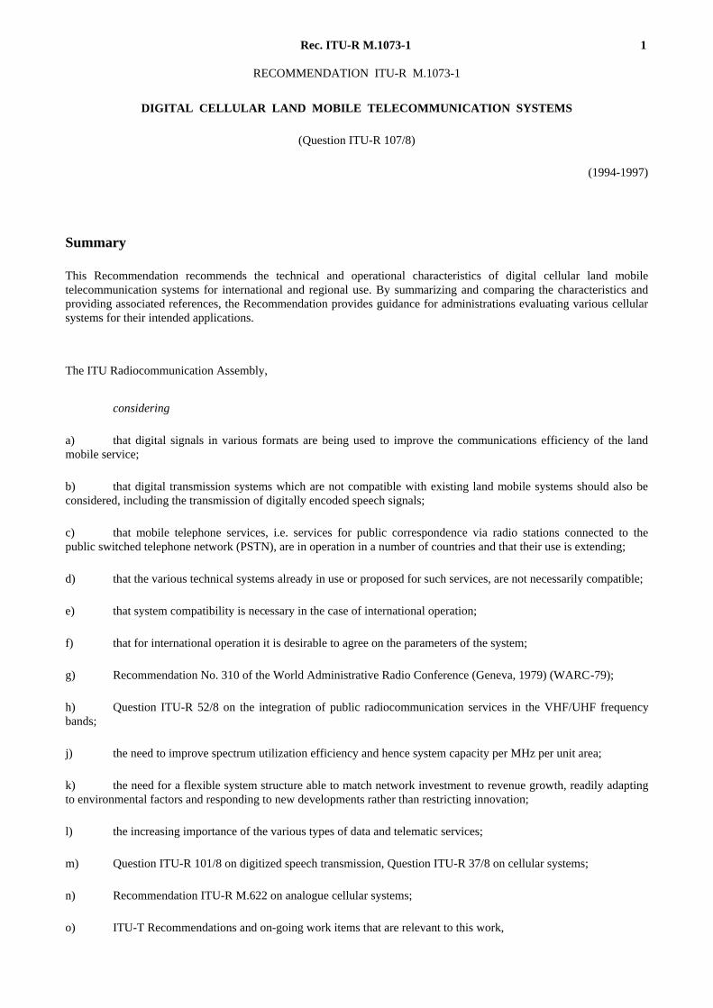
Figure 1 shows the basic system architecture for a DCLMTS, including the major functional components. Thecommunication protocols are specified according to the 7-layer OSI model, while the interfaces between mobileswitching centres (MSCs) and the interfaces to the ISDN, PSTN and PDN are all specified according toITU-T Recommendations. The numbering plan also follows ITU-T Recommendations.
5 Systems being installed or planned
General characteristics of the systems are given in Annex 1. Annexes 2 to 8 give a general description of specificsystems.
4 Rec. ITU-R M.1073-1
1073-01
MS
MS
BS
EIR
MSC
AUC
HLR
VLR
OMC
MSC
Fixednetworks
PDNSPSTNISDN
Interfacewith the fixed networks
Radiointerface
Physical connection
Logical relationships
FIGURE 1
Network architecture
AUC: BS:EIR: HLR: MS: MSC: OMC: VLR:
authentication centrebase stationequipment identity registerhome location registermobile stationmobile services switching centreoperation and maintenance centrevisitor location register
FIGURE 1/1073...[1073-1] = 17 CM
ANNEX 1
Systems being installed or planned
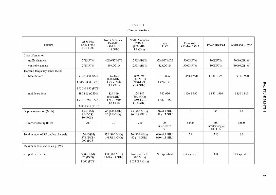
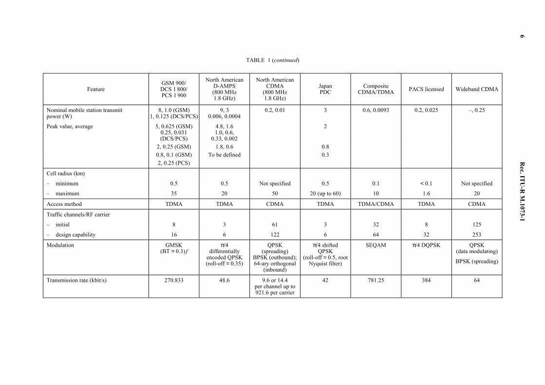
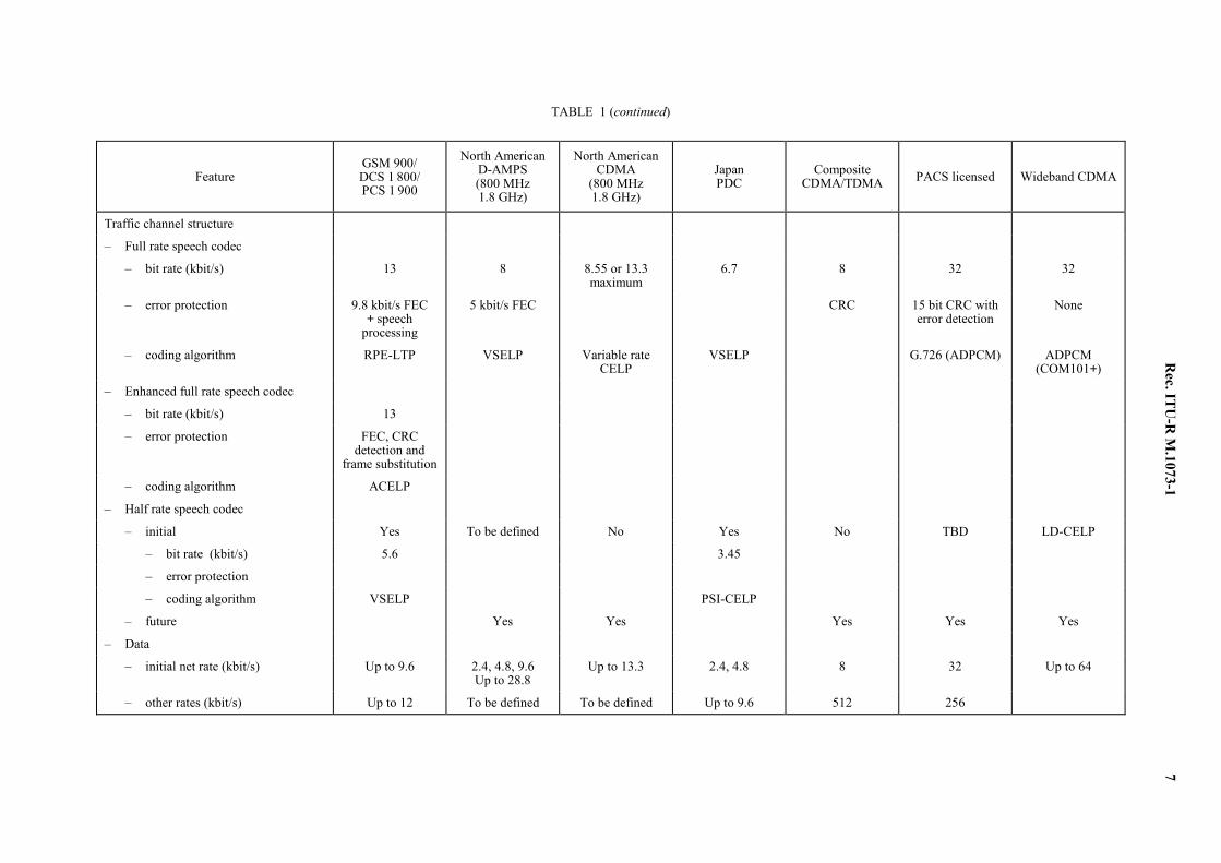
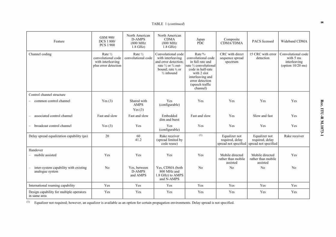
High capacity digital wireless systems are being developed in Europe, North America and Japan. Each of these systemshas the basic objectives and characteristics outlined in the Recommendation. However each is being developed with aslightly different focus and with different constraints. These systems are described in Annexes 2 through 8 and their coreparameters are presented in Table 1.
Rec. ITU
-R M
.1073-1 5
TABLE 1
Core parameters
Feature
GSM 900/ DCS 1 800/ PCS 1 900
North American D-AMPS (800 MHz 1.8 GHz)
North American CDMA
(800 MHz 1.8 GHz)
Japan PDC
Composite
CDMA/TDMA
PACS licensed
Wideband CDMA
Class of emission
– traffic channels 271KF7W 40K0G7WDT 1250K0B1W 32K0G7WDE 5000KF7W 300KF7W 5000K0B1W
– control channels 271KF7W 40K0G1D 1250K0B1W 32K0G1D 5000KF7W 300KF7W 5000K0B1W
Transmit frequency bands (MHz)
– base stations 935-960 (GSM) 869-894 869-894 810-826 1 850-1 990 1 930-1 990 1 930-1 990 (800 MHz) (800 MHz) 1 805-1 880 (DCS) 1 930-1 990 1 930-1 990 1 477-1 501 (1.8 GHz) (1.8 GHz)
1 930 -1 990 (PCS)
– mobile stations 890-915 (GSM) 824-849 824-849 940-956 1 850-1 990 1 850-1 910 1 850-1 910 (800 MHz) (800 MHz) 1 710-1 785 (DCS) 1 850-1 910 1 850-1 910 1 429-1 453 (1.8 GHz) (1.8 GHz) 1 850-1 910 (PCS)
Duplex separation (MHz) 45 (GSM) 45 (800 MHz) 45 (800 MHz) 130 (0.9 GHz) 0 80 80 95 (DCS) 80 (1.8 GHz) 80 (1.8 GHz) 48 (1.5 GHz) 80 (PCS)
RF carrier spacing (kHz) 200 30 1 250 25 5 000 300 5 000 interleaved Interleaving at 50 100 kHz
Total number of RF duplex channels 124 (GSM) 832 (800 MHz) 20 (800 MHz) 640 (0.9 GHz) 28 256 12 374 (DCS) 1 985(1.8 GHz) 47 (1.8 GHz) 960 (1.5 GHz) 299 (PCS)
Maximum base station e.r.p. (W)
– peak RF carrier 300 (GSM) 300 (800 MHz) Not specified Not specified Not specified 0.8 Not specified 20 (DCS) 1 000 (1.8 GHz) (800 MHz) 1 000 (PCS) 1 034 (1.8 GHz)
6
Rec. ITU
-R M
.1073-1
TABLE 1 (continued)
Feature
GSM 900/ DCS 1 800/ PCS 1 900
North American D-AMPS (800 MHz 1.8 GHz)
North American CDMA
(800 MHz 1.8 GHz)
Japan PDC
Composite
CDMA/TDMA
PACS licensed
Wideband CDMA
Nominal mobile station transmit 8, 1.0 (GSM) 9, 3 0.2, 0.01 3 0.6, 0.0093 0.2, 0.025 –, 0.25 power (W) 1, 0.125 (DCS/PCS) 0.006, 0.0004
Peak value, average 5, 0.625 (GSM) 4.8, 1.6 2 0.25, 0.031 1.0, 0.6, (DCS/PCS) 0.33, 0.002 2, 0.25 (GSM) 1.8, 0.6 0.8 0.8, 0.1 (GSM) To be defined 0.3 2, 0.25 (PCS)
Cell radius (km)
– minimum 0.5 0.5 Not specified 0.5 0.1 < 0.1 Not specified
– maximum 35 20 50 20 (up to 60) 10 1.6 20
Access method TDMA TDMA CDMA TDMA TDMA/CDMA TDMA CDMA
Traffic channels/RF carrier
– initial 8 3 61 3 32 8 125
– design capability 16 6 122 6 64 32 253
Modulation GMSK (BT = 0.3) f
π/4 differentially
encoded QPSK (roll-off = 0.35)
QPSK (spreading)
BPSK (outbound); 64-ary orthogonal
(inbound)
π/4 shifted QPSK
(roll-off = 0.5, root Nyquist filter)
SEQAM π/4 DQPSK QPSK (data modulating)
BPSK (spreading)
Transmission rate (kbit/s) 270.833 48.6 9.6 or 14.4 per channel up to 921.6 per carrier
42 781.25 384 64
Rec. ITU
-R M
.1073-1 7
TABLE 1 (continued)
Feature
GSM 900/ DCS 1 800/ PCS 1 900
North American D-AMPS (800 MHz 1.8 GHz)
North American CDMA
(800 MHz 1.8 GHz)
Japan PDC
Composite
CDMA/TDMA
PACS licensed
Wideband CDMA
Traffic channel structure
– Full rate speech codec
– bit rate (kbit/s) 13 8 8.55 or 13.3 maximum
6.7 8 32 32
– error protection 9.8 kbit/s FEC + speech
processing
5 kbit/s FEC CRC 15 bit CRC with error detection
None
– coding algorithm RPE-LTP VSELP Variable rate CELP
VSELP G.726 (ADPCM) ADPCM (COM101+)
– Enhanced full rate speech codec
– bit rate (kbit/s) 13
– error protection FEC, CRC detection and
frame substitution
– coding algorithm ACELP
– Half rate speech codec
– initial Yes To be defined No Yes No TBD LD-CELP
– bit rate (kbit/s) 5.6 3.45
– error protection
– coding algorithm VSELP PSI-CELP
– future Yes Yes Yes Yes Yes
– Data
– initial net rate (kbit/s) Up to 9.6 2.4, 4.8, 9.6 Up to 28.8
Up to 13.3 2.4, 4.8 8 32 Up to 64
– other rates (kbit/s) Up to 12 To be defined To be defined Up to 9.6 512 256
8
Rec. ITU
-R M
.1073-1
TABLE 1 (continued)
Feature
GSM 900/ DCS 1 800/ PCS 1 900
North American D-AMPS (800 MHz 1.8 GHz)
North American CDMA
(800 MHz 1.8 GHz)
Japan PDC
Composite
CDMA/TDMA
PACS licensed
Wideband CDMA
Channel coding Rate ½ convolutional code with interleaving
plus error detection
Rate ½ convolutional code
Convolutional code with interleaving
and error detection; rate ½ or ¾ out-bound; rate 1⁄3 or
½ inbound
Rate 9⁄17 convolutional code
in full rate and rate ½ convolutional
code in half-rate with 2 slot
interleaving and error detection (speech traffic
channel)
CRC with direct sequence spread
spectrum
15 CRC with error detection
Convolutional code with 5 ms
interleaving (option 10/20 ms)
Control channel structure
– common control channel Yes (3) Shared with Yes Yes Yes Yes Yes AMPS (configurable) Yes (3)
– associated control channel Fast and slow Fast and slow Embedded dim and burst
Fast and slow Yes Slow and fast Yes
– broadcast control channel Yes (3) Yes Yes Yes Yes Yes Yes (configurable)
Delay spread equalization capability (µs) 20 60 41.2
Rake receiver (spread limited by
code reuse)
(1) Equalizer not required, delay
spread not specified
Equalizer not required, delay
spread not specified
Rake receiver
Handover – mobile assisted Yes Yes Yes Yes Mobile directed
rather than mobile assisted
Mobile directed rather than mobile
assisted
Yes
– inter-system capability with existing analogue system
No Yes, between D-AMPS
and AMPS
Yes, CDMA (both 800 MHz and
1.8 GHz) to AMPS and N-AMPS
No No No No
International roaming capability Yes Yes Yes Yes Yes Yes Yes
Design capability for multiple operators in same area
Yes Yes Yes Yes Yes Yes Yes
(1) Equalizer not required; however, an equalizer is available as an option for certain propagation environments. Delay spread is not specified.
Rec. ITU-R M.1073-1 9
ANNEX 2
General description of the GSM system
1 Introduction
The characteristics of the GSM system that are common to most of the digital cellular systems can be found in Annex 1.Therefore this Annex highlights only original aspects of the GSM system and, in fact, only parts of them.
The driving force of the GSM has been its international layout based on a common availability of virtually “clear”frequency bands. This situation offered a unique opportunity of optimizing the usage of new technologies, and thereforespectrum efficiency, with a rather limited number of constraints. A very advanced radio design was therefore possible.
The GSM system is applicable to the 900 MHz band (GSM 900), the 1 800 MHz band (DCS 1 800) and the 1 900 MHzband (PCS 1 900). Full detailed information on the specifications of the GSM system is given in ETSI, GeneralReferences.
2 Services
In the process of drafting the GSM standard, the details of the implementation of each particular service together withthe required interworking mechanisms have been specified in order to offer full access to the services while roaming,and to minimize the complexity of the mobile station.
2.1 Bearer services
The bearer services offered by the GSM PLMN include transparent and non-transparent data services for circuit as wellas packet mode, up to a net data rate of 12 kbit/s.
2.2 Teleservices
Among the main teleservices supported by the GSM are:
– speech, i.e. telephony and emergency calls,
– short message service,
– data message handling system access,
– videotex,
– facsimile.
2.3 Supplementary services
The supplementary services offered by GSM operators can be divided into four main groups:
– call forwarding,
– call completion,
– advice of charge,
– call restriction.
2.4 Security aspects
Further to the provision of a wide range of services, the GSM system has also been designed to ensure a high level ofsecurity. Therefore security features are provided to protect the access to the services and the privacy of user-relatedinformation. The following security features are implemented in the GSM system:
– subscriber identity confidentiality : it ensures that the mobile subscriber identity (IMSI) cannot be disclosed;
– subscriber identity authentication : it verifies that the subscriber identity sent by the mobile is the one claimed (notduplicated or impersonated);
10 Rec. ITU-R M.1073-1
– user data confidentiality : it ensures that the user data, including speech, transferred on the radio path cannot bedisclosed by unauthorized bodies;
– signalling information element confidentiality : it is the property that a given piece of signalling information(subscriber and equipment identities, directory numbers, etc.) exchanged on the radio path cannot be used byunauthorized individuals or entities.
The IMSI is the information which uniquely identifies the subscriber, and that has to be present and valid to allow theoperation of the mobile station.
Each mobile station has a unique identity that shall be implemented by the manufacturer: the international mobileequipment identity (IMEI).
The security functions for authentication of the subscriber related information, and all processes involving theauthentication key are contained in a removable piece of the mobile station called the subscriber identity module (SIM).
3 Overview of the system
The GSM system has been standardized by administrations, operators and manufacturers in over 16 European countriesand in other countries around the world in order to provide full service access to international roamers. The standard ofthe GSM is described in terms of interfaces and functional entities.
Two interfaces are mandatory: the radio interface (Um) and the interface “A” between the mobile services switchingcentre (MSC) and the base station system (BSS). A further interface “A bis” within the BSS system is being specifiedbut its implementation is not mandatory.
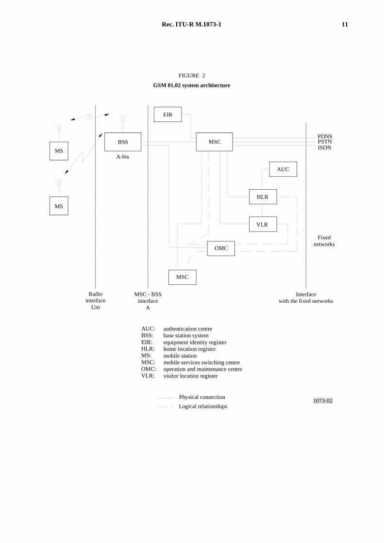
The functional architecture is given in Fig. 2. It shows:
– the MSC, the home location register (HLR), and the visitor location register (VLR), where the networking andswitching functions are performed;
– the BSS which includes the base stations controller (BSC) and the base station transceivers;
– the operation and maintenance centre (OMC);
– the mobile station (MS).
The MAP is the mobile application part of ITU-T Signalling System No. 7 which has been specified to allow the routingof calls to MS which have roamed to different MSC areas or to different networks.
The MSC, HLR and VLR execute interworking with partner networks, call control and encryption of signalling and userspeech and data. These functions also include authentication of the mobile user, location updating as roaming occurs,paging of the mobile to indicate incoming calls.
The BSS performs the radio channel management functions which include administration of the radio channelconfigurations, allocations of radio channels and link supervision, scheduling of messages on broadcast channels, choiceof frequency hopping sequences whenever needed, and power controls.
4 Technical radio characteristics
These characteristics are specified in GSM Recommendation Series-05 and 06 and in PCS 1 900 ANSI StandardJ-STD-007 Volume 1 and Volume 3.
4.1 RF equipment requirements
In accordance with GSM Recommendation 05.05 and in PCS 1 900 ANSI Standard J-STD-007 Volume 1 and Volume 3.
Rec. ITU-R M.1073-1 11
1073-02
MS
MS
BSS
EIR
MSC
AUC
HLR
VLR
OMC
MSC
Interfacewith the fixed networks
Fixednetworks
PDNSPSTNISDN
A-bis
Radiointerface
Um
MSC - BSSinterface
A
Physical connection
Logical relationships
FIGURE 2
GSM 01.02 system architecture
AUC: BSS:EIR: HLR: MS: MSC: OMC: VLR:
authentication centrebase station systemequipment identity registerhome location registermobile stationmobile services switching centreoperation and maintenance centrevisitor location register
FIGURE 2/1073...[1073-2] = 17 CM
12 Rec. ITU-R M.1073-1
4.2 Carrier spacing
A 200 kHz carrier spacing yields at least 18 dB adjacent RF channel selectivity within the system. The second adjacentRF channel at 400 kHz spacing yields at least 50 dB selectivity within the system. The corresponding third adjacentRF channel selectivity yields at least 58 dB.
Frequency hopping is a possible feature.
4.3 Class of emission
71KF7W according to Radio Regulations 4, i.e. Gaussian minimum shift keying GMSK (BT = 0.3) with a modulationrate of 270.83 kbit/s per carrier, using a time division multiple access (TDMA) scheme for eight basic physical channels.
4.4 Cell structure and carrier reuse
It is possible to use large cells (up to 35 km base-mobile distance) in rural areas as well as small cells (down to 1 kmdiameter) in urban areas.
Extended cell operation ranging up to 120 km base-mobile distance is also possible.
In areas of high peak traffic density (e.g. city centres) it is possible to build up a sector cell structure using directionalantennas with a channel concentration at the traffic peak area.
Co-channel protection ratio down to C /I = 9 dB is acceptable by the system and yields a possible reuse corresponding toa 9-cell cluster (3-cell reuse patterns with three sectors per cell).
The receiver sensitivity, similar to that of existing analogue systems, allows an average transmit power about 9 dB lowerthan current analogue systems, given the same requirements for maximum cell sizes and the same RF device choices.
4.5 Time-slots and TDMA frames
A burst containing 148 bits, corresponding to 114 coded bits, is sent within a time-slot duration of 0.577 ms. A set ofeight time-slots is used to build up a TDMA frame containing eight basic physical channels. Each physical channel haslogical channels mapped on it, i.e. the traffic channels and control channels.
The useful information is distributed in the time-slots in a manner allowing recovery from total erasure of sometime-slots.
Two multiframe structures are defined: one consisting of 26 TDMA frames (recurrence interval of 120 ms) for trafficchannels and their associated control channels, and one for the other control channels comprising 51 TDMA frames(recurrence interval of 236 ms).
4.6 Traffic channels
4.6.1 Full- and half-rate traffic channels
The system is able to support both full and half-rate traffic channels, corresponding respectively to the gross bit ratesof 22.8 and 11.4 kbit/s. The half-rate channel is obtained by the use of only half of the time-slots used by the full-ratechannel. A carrier therefore provides up to 8 full-rate or 16 half-rate traffic channels (or a combination of both) withtheir respective associated control channels.
4.6.2 Speech traffic channels
The full-rate speech codec, and the associated error correction and detection mechanisms have been defined in the GSMstandard. Speech frames of 20 ms, each comprising 260 bits, provide a net bit rate of 13 kbit/s. The coding method,
Rec. ITU-R M.1073-1 13
“regular pulse excited linear prediction coding with long-term prediction (RPE-LTP)”, has been designed to be robust inthe presence of transmission errors, and to offer a quality close to that of the PSTN while using a limited bit rate.
Error correction (consisting of a 1/2 rate convolutional code) and interleaving schemes, to selectively protect the mostimportant bits within the speech frame (70% of the bits) have been specified. Furthermore, an error detection mechanismhas been included, associated with extrapolation techniques which have been described and/or recommended, in order tominimize the impairment of speech quality if speech frames are not correctly received. The usage of speech activitydetectors has also been specified in the GSM system. Details can be found in the GSM standard.
In PCS 1 900, an enhanced full-rate codec has been defined, providing near-wireline audio quality under errorlessconditions. The PCS 1 900 messaging also supports the possibility of multiple codecs.
4.6.3 Data traffic channels
Transparent and non-transparent data services of up to 9.6 kbit/s are supported by different rate adaptations, channelcoding and interleaving schemes, on full-rate and/or half-rate channels.
Unrestricted digital bearer services with a net bit rate of 12 kbit/s are also supported.
4.6.4 Discontinuous transmission
All traffic channels may use, when possible, discontinuous transmission (i.e. the transmitter is silent when no relevantinformation is to be transmitted). In the case of speech this is possible due to the specification of speech activitydetectors.
This feature, combined with frequency hopping which introduces interferer diversity, is expected to increase the systemcapacity. It will also prolong battery life in hand-held portable stations.
4.7 Control channels
Three categories of control channels are defined: broadcast, common and dedicated.
4.7.1 Broadcast channels
Broadcast channels are divided into frequency correction, synchronization and broadcast control channels.
4.7.2 Common control channels
Common control channels are divided into paging, random access and access grant channels.
4.7.3 Dedicated control channels
Dedicated control channels are divided into slow and fast associated control channels, as well as stand-alone dedicatedcontrol channels with their associated control channels. Also under this category a cell broadcast channel is defined tocarry short messages service cell broadcast.
Short message service, mobile terminated and mobile originated point-to-point calls, are supported by the stand-alonededicated control channel or the slow associated control channel.
5 Operational characteristics
5.1 Cell selection
Whilst in idle mode the mobile station is camped on a cell from which it can reliably decode downlink data, and withwhich it has a high probability of communicating on the uplink.
14 Rec. ITU-R M.1073-1
The cell selection is based on path loss criteria. If these criteria are not met, or if the mobile station fails to decodepaging blocks or fails to access the uplink, the mobile station starts to re-select.
5.2 Location updating (roaming)
Roaming is performed in accordance with Recommendation ITU-R M.624.
The mobile station evaluates the received signal and initiates the location updating procedure when necessary.
Roaming is possible between mobile service switching centres (MSCs) and between countries.
5.3 Communication protocols
The communication protocols are layered according to the OSI model and are specified in the GSM Recommendations.
The network layer is divided into three sub-layers: call control, mobile management and radio resource management.
The link layer is based on LAPD protocols and makes use of the control channels. Messages between link layer peerentities are source coded into 23 octets, i.e. 184 bits.
5.4 Call setup
5.4.1 Mobile originated call set-up
The procedure starts on the random access channel to set up a radio resource. Then authentication is done on the mobilemanagement sub-layer. After ciphering and assignment has been confirmed, the call-setup is confirmed on the callcontrol sub-layer.
5.4.2 Mobile terminated call set-up
After paging from the network the same procedure as § 5.4.1 is followed.
5.5 Handover
Handover is required to maintain a call in progress as a mobile passes from one cell coverage area to another and mayalso be employed to meet network management requirements, i.e. relief of congestion (network-directed handover).
The handover is done either from a channel on one cell to another channel on another cell, or between channels of thesame cell.
The handover strategy employed by the network for radio link control determines the handover decision that will bemade based on the measurement results reported by the mobile and base stations and the various parameters set for eachcell. The exact handover strategies are determined by the network operator.
A procedure is implemented in the mobile station which monitors the downlink signal level and quality from its servingcell, the downlink signal level and the colour code of surrounding cells.
A procedure is implemented in the base station which monitors the uplink signal level and quality from each mobilestation being served by the cell.
These radio link measurements are also used for RF power control.
Handover is possible between location areas and between different MSCs belonging to the same PLMN.
Rec. ITU-R M.1073-1 15
5.6 Radio link failure
The criteria for determining radio link failure are specified in order to ensure that calls which fail, either from loss ofradio coverage or unacceptable interference, are satisfactorily handled by the network. Radio link failure results in eithercall re-establishment or release of the call in progress.
The criterion for determining radio link failure in the mobile station is based on the success rate of decoding messageson the downlink slow associated control channel.
5.7 Signalling between base station and MSC
The signalling follows a layered approach similar to ISDN in accordance with GSM Recommendations and PCS1 900 standards.
5.8 ISDN, PDN and PSTN interfaces
These interfaces are in accordance with ITU-T Recommendations Q.700 and Q.1000 Series.
5.9 Numbering plan
The numbering plan is in accordance with ITU-T Recommendations E.164, E.212 and E.213.
5.10 Signalling between MSCs
The signalling between MSCs uses ITU-T Signalling System No. 7 (ITU-T Recommendations E.214, Q.700 Series andGSM 09.02 or ITU-T Recommendation Q.1051 and for PCS 1 900 – ANSI SS No. 7).
BIBLIOGRAPHY
EIA/TIA IS-651. SS No. 7-based A-Interface. Electronic Industries Association/Telecommunications Industry Association, UnitedStates of America.
EIA/TIA IS-652. PCN-PCN Intersystem Operations Based on DCS 1 900, United States of America.
ANNEX 3
IS-136 based TDMA air interface standard
1 Introduction
The new North American TDMA PCS air interface compatibility standard is designed to provide optimized multi-userservice performance under the dynamic fading conditions that characterize the wireless PCS channels. The specificationis fully compatible and interoperable with earlier generation advanced mobile phone service (AMPS) based cellularspecifications – EIA/TIA-553, IS-54 Rev. B and IS-136 – and thus can be used to accelerate the deployment of PCS on aworldwide basis. Because of the inherent backward compatibility with the precursory AMPS specifications, currentcellular systems can be migrated to immediately support PCS with the availability of the following benefits to systemoperators:
– 100% infrastructure reuse,
– deployment cost minimization,
– immediate large scale coverage.
16 Rec. ITU-R M.1073-1
The system is designed around the IS-136 800 MHz cellular standard, but is all digital and features a new digital controlchannel (DCCH) which supports enhanced multi-user access and services including:
– optional multiple sleep modes for extended battery stand-by time,
– short message service,
– hierarchical cell structure support for microcell and private systems realization.
The complete North American TDMA PCS specification comprises the following Standards:
– ANSI J-STD-009: PCS IS-136 Based Mobile Station Minimum Performance 1 900 MHz Standard
– ANSI J-STD-010: PCS IS-136 Based Base Station Minimum Performance 1 900 MHz Standard
– ANSI J-STD-011: PCS IS-136 Based Air Interface Compatibility 1 900 MHz Standard.
2 Technical overview
2.1 Frequency band and channelization
The PCS broadband spectrum allocation defines the frequencies over which the base and mobile station transmit. Theforward transmit frequency range is 1 930-1 990 MHz, and the reverse transmit frequency range is 1 850-1 910 MHz.
The PCS band plan is segmented into radio-frequency channels of bandwidth 30 kHz. The RF channels are frequencydivision duplexed with a duplex distance of 80.04 MHz. The total bandwidth per duplex RF channel is thus2 × 30 kHz = 60 kHz. There are 1 985 duplex frequencies.
Traffic channels are time division multiplexed on each RF channel. Each RF channel carries six time-slots. This allowsfor six half-rate traffic channels when each time-slot is individually used. These time-slots are paired in the order (1, 4),(2, 5), or (3, 6) for assignment as three full-rate traffic channels.
2.2 Baseband modulation and channel bit rate
Baseband modulation is specified as π/4 DQPSK, using a root-raised cosine baseband shaping filter, with shaping factorα = 0.35. There are 2 bits per symbol. The channel bit rate is 48.6 kbit/s allowing for a maximum usable bit rate of39 kbit/s if all three full-rate time-slots are used.
2.3 Multiplexing and multiple access
The air interface standard employs a full-duplex time division multiple access (TDMA) in combination with FDMA.
1073-03
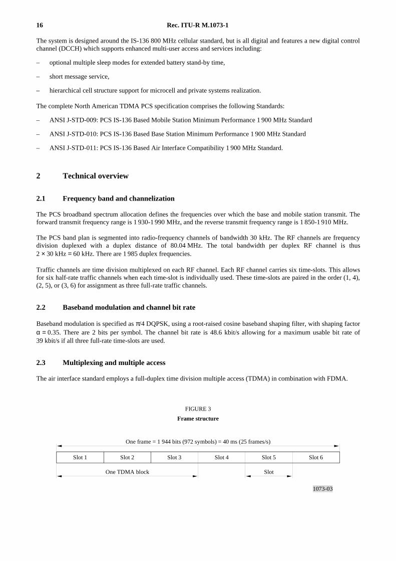
FIGURE 3
Frame structure
Slot 1 Slot 2 Slot 3 Slot 4 Slot 5 Slot 6
One frame = 1 944 bits (972 symbols) = 40 ms (25 frames/s)
One TDMA block Slot
FIGURE 3/1073...[1073-3] = 3.5 CM
Rec. ITU-R M.1073-1 17
The TDMA frame is 40 ms long, and consists of six time-slots (6.7 ms in duration). Each frame is subdivided into twoTDMA blocks, and consists of three time-slots. Each full-rate channel allocates two time-slots per TDMA frame(40 ms), which is equal to one time-slot per TDMA block (20 ms). Each time-slot is 324 bits long, and can carry anumber of logical channels. The digital control channel (DCCH) comprises a random access channel (RACH), abroadcast control channel (BCCH), an SMS, paging and access response channel (SPACH), and a shared channelfeedback channel (SCF). The digital traffic channel (DTC) comprises a slow associated control channel (SACCH) a fastassociated control channel (FACCH), and a user information channel. The user information can be data, point-to-pointSMS, or speech.
2.4 Power specifications
2.4.1 Base station
A maximum base station output power is specified at 1 640 W e.i.r.p. as determined by the FCC ruling.
2.4.2 Mobile station
Depending on the power class, several levels of mobile station power are allowed, with maximum transmit power ofeither 1.0 W or 0.6 W e.r.p. For full-rate channels the average output powers are 0.33 W and 0.2 W respectively.
Below each maximum level a number of operational power control steps have been defined, permitting actual operationdown to 6 mW (0.2 mW average) and 0.4 mW (0.13 mW average) respectively. These power control steps will normallybe used to operate the mobile station at the minimum necessary power level for the prevailing propagation andinterference environment.
Since discontinuous-transmission techniques are allowed in the reverse direction (from MS to BS), the actual transmittedpower is dependent on how often the talker is “active” in talking state.
2.4.3 Power control characteristics
Power control is supported on both the forward and reverse links. On the forward link it is supported on a carrier basis,while on the reverse support occurs on a channel basis.
2.5 Performance characteristics
2.5.1 Delay spread
An equalizer is required for the mobile station. The equalizer is robust to intersymbol interference, with delay intervalsless than 41.2 µs. The delay is defined as the time difference between the first and last significant rays. The equalizer isnot sensitive to the shape of the delay spread profile, and can adapt to channel variations for vehicle speeds up to atleast 110 km/h.
2.5.2 Doppler frequency
The maximum tolerable doppler frequency is dependent on the receiver implementation and other channel conditions.All base stations and mobile stations can handle at least up to 200 Hz.
2.5.3 End-to-end delay
The end-to-end delay is specified at less than 100 ms for PCS-to-wireline, and less than 200 ms for PCS-to-PCS.
2.6 Speech services
The immediately supported speech coder is the 7.95 kbit/s ITU-T Recommendation G.714 VSELP. Signalling forsupport of multiple speech coders is provided. Within the immediate future the system will feature an advanced speechcoder.
18 Rec. ITU-R M.1073-1
The current VSELP voice coder provides quality comparable to landline in a multipath environment. Both speakerrecognition and the capability to carry recognizable music are supported. User ability to hear in a noisy environment issupported, with the artifacts of the voice digitization process sounding much like traditional background noise.Background noise feedback and noise introduced by the wireless network are minimized.
The air interface supports calls with and without speech activity compression on the reverse channel (MS to BS).
2.7 Data services
Two types of circuit-switched data services are immediately supported. These are asynchronous data and G3 fax:
– Asynchronous data service with modem-based access to PSTN subscribers : User data is transported in digital formover the radio interface. Modems reside in the PCS system. All popular modems are supported (e.g., V.22, V.32,V.32 bis, V.34). The asynchronous data service can access PSPDN (public switched packet data network)through X.3 PADS.
– Group-3 fax service : The fax service is based on the PC-fax standard according to EIA/TIA-592 and IS-134. Faxdata is transported in digital form over the radio interface. Fax modems reside in the PCS system. Error correctionmode and binary file transfer (T.434) is supported.
2.7.1 Data rates
All popular data rates up to 28.8 kbit/s are supported.
2.7.2 Data reliability
The reliability of customer information is assured through forward error correction and ARQ. The forward errordetection/correction (FEC) code is 5/6-convolutional code. Each TDMA time-slot contains one radio link protocol 1(RLP1, IS-130) frame, i.e., maximum 6 RLP1 frames per TDMA frame. If there are errors not corrected by FEC in areceived RLP1 frame, then RLP1 will retransmit the frame until it is positively acknowledged by the receiver. Everyerroneous RLP1 frame is retransmitted at least once. There is no maximum number of retransmissions, only a timermaking sure the link gets something across in error-free condition.
2.7.3 Error probability
The error probability depends on the CRC code. Two codes are supported, one 16-bit and one 24-bit. Average user dataerror rate is better than 1 × 10– 6 for the 16-bit CRC code, and better than 1 × 10– 8 for the 24-bit CRC code.
2.8 Call handling
A control channel (DCCH) is provided which consists of several time multiplexed logical channels.
The DCCH may be assigned to any frequency which provides maximum flexibility for the system operator’s frequencymanagement. Two means have been provided to assist the mobile in finding a DCCH:
– DCCH locator provided on all traffic channels,
– DCCH probability blocks.
The forward DCCH (FDCCH) and reverse DCCH (RDCCH) are structured according to the OSI layered model,i.e. distinct layer 1 (physical layer), layer 2 (link layer) and layer 3 (message level).
Rec. ITU-R M.1073-1 19
TABLE 2
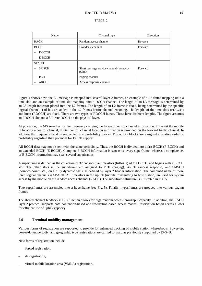
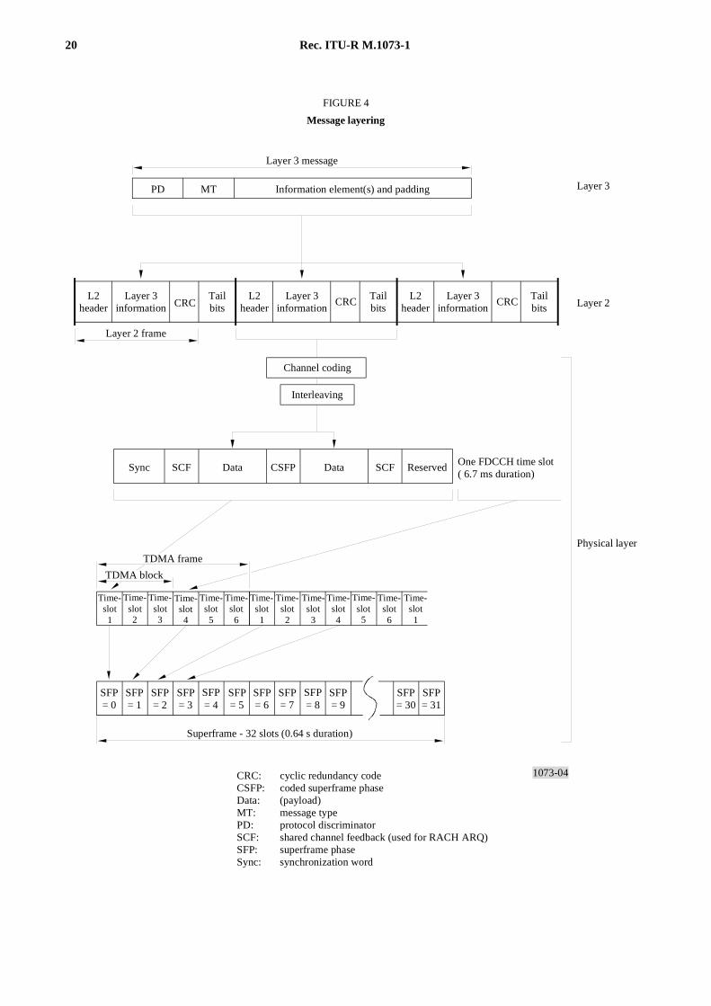
Figure 4 shows how one L3 message is mapped into several layer 2 frames, an example of a L2 frame mapping onto atime-slot, and an example of time-slot mapping onto a DCCH channel. The length of an L3 message is determined byan L3 length indicator placed into the L2 frames. The length of an L2 frame is fixed, being determined by the specificlogical channel. Tail bits are added to the L2 frames before channel encoding. The lengths of the time-slots (FDCCH)and burst (RDCCH) are fixed. There are two types of RDCCH bursts. These have different lengths. The figure assumesan FDCCH slot and a full-rate DCCH on the physical layer.
At power on, the MS searches for the frequency carrying the forward control channel information. To assist the mobilein locating a control channel, digital control channel location information is provided on the forward traffic channel. Inaddition the frequency band is segmented into probability blocks. Probability blocks are assigned a relative order ofprobability regarding their potential for DCCH support.
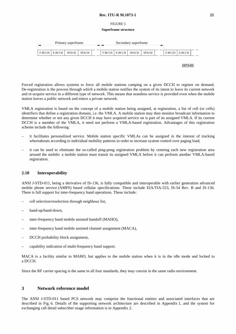
All BCCH data may not be sent with the same periodicity. Thus, the BCCH is divided into a fast BCCH (F-BCCH) andan extended BCCH (E-BCCH). Complete F-BCCH information is sent once every superframe, whereas a complete setof E-BCCH information may span several superframes.
A superframe is defined as the collection of 32 consecutive time-slots (full-rate) of the DCCH, and begins with a BCCHslot. The other slots in the superframe are assigned to PCH (paging), ARCH (access response) and SMSCH(point-to-point SMS) on a fully dynamic basis, as defined by layer 2 header information. The combined name of thesethree logical channels is SPACH. All time-slots in the uplink (mobile transmitting to base station) are used for systemaccess by the mobile on the random access channel (RACH). The superframe structure is illustrated in Fig. 5.
Two superframes are assembled into a hyperframe (see Fig. 5). Finally, hyperframes are grouped into various pagingframes.
The shared channel feedback (SCF) function allows for high random access throughput capacity. In addition, the RACHlayer 2 protocol supports both contention-based and reservation-based access modes. Reservation based access allowsfor efficient use of uplink capacity.
2.9 Terminal mobility management
Various forms of registration are supported to provide for enhanced tracking of mobile station whereabouts. Power-up,power-down, periodic, and geographic type registrations are carried forward as previously supported by IS-54B.
New forms of registration include:
– forced registration,
– de-registration,
– virtual mobile location area (VMLA) registration.
Name Channel type Direction
RACH Random access channel Reverse
BCCH Broadcast channel Forward
– F-BCCH
– E-BCCH
SPACH
– SMSCH Short message service channel (point-to-point)
Forward
– PCH Paging channel
– ARCH Access response channel
20 Rec. ITU-R M.1073-1
1073-04
PD MT
SCF CSFP SCF
SFP= 0
SFP= 1
SFP= 2
SFP= 3
SFP= 4
SFP= 5
SFP= 6
SFP= 7
SFP= 8
SFP= 9
SFP= 30
SFP= 31
CRC CRC CRC
FIGURE 4
Message layering
One FDCCH time slot( 6.7 ms duration)
Information element(s) and padding
Channel coding
Interleaving
Sync Data Data
Time-slot1
Layer 3 message
Layer 3
Layer 2
Physical layer
TDMA block
TDMA frame
Superframe - 32 slots (0.64 s duration)
Time-slot2
Time-slot3
Time-slot4
Time-slot5
Time-slot6
Time-slot1
Time-slot2
Time-slot3
Time-slot4
Time-slot5
Time-slot6
Time-slot1
L2header
Layer 3information
Layer 3information
Tailbits
L2header
Layer 3information
Tailbits
Layer 2 frame
Tailbits
L2header
CRC: cyclic redundancy codeCSFP: coded superframe phaseData: (payload)MT: message typePD: protocol discriminatorSCF: shared channel feedback (used for RACH ARQ)SFP: superframe phaseSync: synchronization word
Reserved
FIGURE 4 [1073-04]= page pleine
Rec. ITU-R M.1073-1 21
1073-05
F-BCCH E-BCCH SPACH SPACH F-BCCH E-BCCH SPACH SPACH F-BCCH E-BCCH
FIGURE 5
Superframe structure
Secondary superframePrimary superframe
FIGURE 5 [1073-05]= 3.5 CM
Forced registration allows systems to force all mobile stations camping on a given DCCH to register on demand.De-registration is the process through which a mobile station notifies the system of its intent to leave its current networkand re-acquire service in a different type of network. This means that seamless service is provided even when the mobilestation leaves a public network and enters a private network.
VMLA registration is based on the concept of a mobile station being assigned, at registration, a list of cell (or cells)identifiers that define a registration domain, i.e. the VMLA. A mobile station may then monitor broadcast information todetermine whether or not any given DCCH it may have acquired service on is part of its assigned VMLA. If its currentDCCH is a member of the VMLA, it need not perform a VMLA-based registration. Advantages of this registrationscheme include the following:
– it facilitates personalized service. Mobile station specific VMLAs can be assigned in the interest of trackingwhereabouts according to individual mobility patterns in order to increase system control over paging load;
– it can be used to eliminate the so-called ping-pong registration problem by centring each new registration areaaround the mobile: a mobile station must transit its assigned VMLA before it can perform another VMLA-basedregistration.
2.10 Interoperability
ANSI J-STD-011, being a derivative of IS-136, is fully compatible and interoperable with earlier generation advancedmobile phone service (AMPS) based cellular specifications. These include EIA/TIA-553, IS-54 Rev. B and IS-136.There is full support for inter-frequency band operations. These include:
– cell selection/reselection through neighbour list,
– hand-up/hand-down,
– inter-frequency band mobile assisted handoff (MAHO),
– inter-frequency band mobile assisted channel assignment (MACA),
– DCCH probability block assignment,
– capability indication of multi-frequency band support.
MACA is a facility similar to MAHO, but applies to the mobile station when it is in the idle mode and locked toa DCCH.
Since the RF carrier spacing is the same in all four standards, they may coexist in the same radio environment.
3 Network reference model
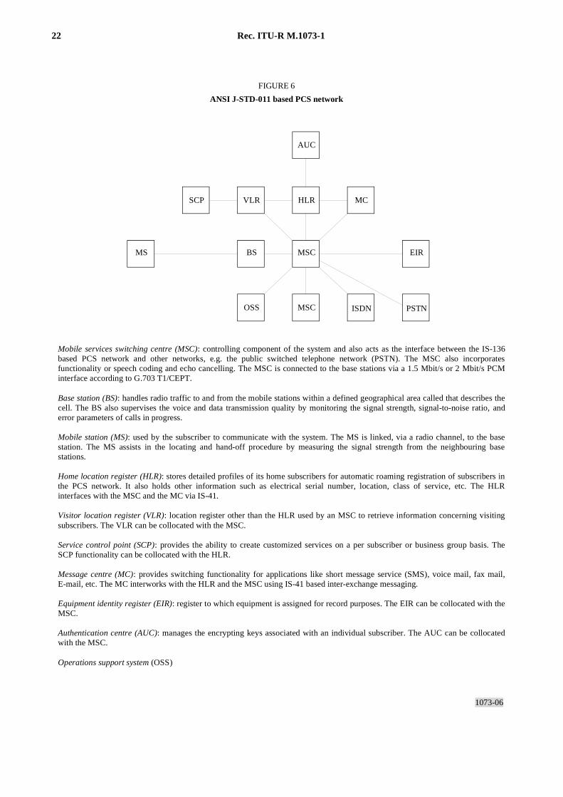
The ANSI J-STD-011 based PCS network may comprise the functional entities and associated interfaces that aredescribed in Fig. 6. Details of the supporting network architecture are described in Appendix 1, and the system forexchanging call detail subscriber usage information is in Appendix 2.
22 Rec. ITU-R M.1073-1
1073-06
FIGURE 6
ANSI J-STD-011 based PCS network
ISDN PSTN
Mobile services switching centre (MSC): controlling component of the system and also acts as the interface between the IS-136 based PCS network and other networks, e.g. the public switched telephone network (PSTN). The MSC also incorporates functionality or speech coding and echo cancelling. The MSC is connected to the base stations via a 1.5 Mbit/s or 2 Mbit/s PCM interface according to G.703 T1/CEPT.
Base station (BS): handles radio traffic to and from the mobile stations within a defined geographical area called that describes the cell. The BS also supervises the voice and data transmission quality by monitoring the signal strength, signal-to-noise ratio, and error parameters of calls in progress.
Mobile station (MS): used by the subscriber to communicate with the system. The MS is linked, via a radio channel, to the base station. The MS assists in the locating and hand-off procedure by measuring the signal strength from the neighbouring base stations.
Home location register (HLR): stores detailed profiles of its home subscribers for automatic roaming registration of subscribers in the PCS network. It also holds other information such as electrical serial number, location, class of service, etc. The HLR interfaces with the MSC and the MC via IS-41.
Visitor location register (VLR): location register other than the HLR used by an MSC to retrieve information concerning visiting subscribers. The VLR can be collocated with the MSC.
Service control point (SCP): provides the ability to create customized services on a per subscriber or business group basis. The SCP functionality can be collocated with the HLR.
Message centre (MC): provides switching functionality for applications like short message service (SMS), voice mail, fax mail, E-mail, etc. The MC interworks with the HLR and the MSC using IS-41 based inter-exchange messaging. Equipment identity register (EIR): register to which equipment is assigned for record purposes. The EIR can be collocated with the MSC.
Authentication centre (AUC): manages the encrypting keys associated with an individual subscriber. The AUC can be collocated with the MSC.
Operations support system (OSS)
MSC
HLR
AUC
MCVLR
MSCOSS
EIRBS
SCP
MS
FIGURE 6 [1073-06]= page pleine
Rec. ITU-R M.1073-1 23
BIBLIOGRAPHY
JTC(AIR)/94.11.03 – 739. Tag-4 Response to 244 Radio System Characterization Report.
T1S1.1/95-160R2. T1S1-14 Mobility Management Application Layer Protocol (MMAP).
ANNEX 4
General description of the Japanese personal digital cellular (PDC)land mobile telecommunication system
1 Introduction
The Japanese personal digital cellular (PDC) PLMTS is specified to provide various services and to accommodate agreat number of subscribers.
The system is applicable to both the 800/900 MHz and the 1.5 GHz bands and supports data, facsimile and ISDNservices. To realize efficient frequency utilization, the RF carrier spacing is 25 kHz in accordance with the existinganalogue standard [RCR, 1995].
2 Overview of the system
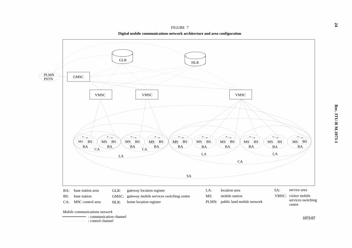
Figure 7 shows an example of the digital mobile communications network architecture and area configuration.
The digital mobile communications network is connected to the PSTN and another PLMN. It is also connected to theISDN by ISDN user part (ISUP) and to the packet switched public data network (PSPDN) via the ISDN.
Gateway mobile services switching centre (GMSC) : This provides a gateway function between the fixed network andthe mobile network.
Visitor mobile services switching centre (VMSC) : This provides a call connection capability both for mobileoriginated/terminated call setups and supplementary services.
Home location register (HLR) : This stores subscriber data and the location of home subscribers, e.g. the mobile stationidentification number and the area where the subscribers belong are registered.
Gateway location register (GLR) : This is provided to temporarily store the data of a terminal moving in from othernetworks. This GLR complements the HLR in which the regular mobile communications service subscriber informationis stored.
Base station (BS) : This provides the radio channel management functions.
Mobile station (MS) : This is an interface terminal and provides multi-service functions to the mobile subscriber.
24R
ec. ITU
-R M
.1073-1
1073-07
FIGURE 7
Digital mobile communications network architecture and area configuration
BA:
BS:
CA:
GLR:
GMSC:
HLR:
LA:
MS:
PLMN:
SA:
VMSC:
base station area
base station
MSC control area
gateway location register
gateway mobile services switching centre
home location register
location area
mobile station
public land mobile network
service area
visitor mobileservices switchingcentre
Mobile communications network: communication channel: control channel
PLMNPSTN
GMSC
GLRHLR
VMSC VMSCVMSC
MS MS MS MS MS MS MS MSBABABABABABABABABABA
BS BS
LALALA
CA
SA
CA CA
BS BS MS BS BS BS BS BS BSMS
FIG
UR
E 7 [1073-07]=
page pleine à l'italienne
Rec. ITU-R M.1073-1 25
3 Main features [RCR, 1995]
3.1 RF interface requirements
– Channel spacing: 25 kHz interleaved channel spacing, 50 kHz channel spacing,
– modulation: π/4 shifted QPSK (roll-off factor; 0.5, root-Nyquist filter),
– access method: TDMA:
– 3 time-slots/25 kHz (for full-rate),
– 6 time-slots/25 kHz (for half-rate),
– transmission bit rate: 42 kbit/s.
3.2 Cell structure and carrier reuse
– Typical cell radius: 0.5-20 km (up to 60 km by time alignment),
– sector cell structure using directional antennas.
3.3 Channel coding (speech traffic channel)
– rate 9/17 convolutional code in full-rate,
– rate 1/2 convolutional code in half-rate,
– two levels of error protection,
– cyclic redundancy code (CRC) to protect the most important bits for speech.
3.4 Time-slots
– Three for full-rate, six for half-rate.
3.5 Traffic channels
– Speech: supports full-rate and half-rate speech codecs:
– full-rate speech codecs (VSELP) of 6.7 kbit/s;
– up to 11.2 kbit/s are allocated to full-rate speech coding and forward error correction;
– half-rate speech codecs (PSI-CELP) of 3.45 kbit/s;
– up to 5.6 kbit/s are allocated to half-rate speech coding and forward error correction.
– Data and other services:
– data transmission system standard (G3 facsimile and modem, ITU-T Recommendation V.42 Annex) isspecified and high-speed data transmission system standard is also specified;
– ISDN sub-rate (8 kbit/s).
3.6 Control channels
– Broadcast control channels (BCCH): control channels for broadcast messages,
– common control channels (CCCH): control channels for signalling, such as paging,
– associated control channels (ACCH): slow ACCH and fast ACCH.

26 Rec. ITU-R M.1073-1
3.7 Cell selection
– While in idle mode, the mobile station monitors the downlink signal level and colour code from its serving cell andsurrounding cells.
3.8 Handover
– Inter-system and intra-system handovers are specified;
– mobile assisted handover:
– this provides the ability for the mobile stations to measure and report both the received signal strength andchannel quality over the current connection as well as the received signal strength on other channels, asrequested by the base station.
3.9 Roaming
– In accordance with Recommendation ITU-R M.624;
– the mobile station evaluates the received signal and coding and initiates the location updating procedure whennecessary;
– roaming is possible between MSCs and between systems.
3.10 System architecture
– Communication protocol: the network communication protocol reference model is designed according to theOSI model;
– interfaces: the interfaces between system function blocks are designed according to ITU-T Recommendations.
3.11 Networking
– ISDN and PSTN interfaces: in accordance with ITU-T Recommendations Q.700 Series;
– numbering plan: in accordance with ITU-T Recommendations E.164, E.212 and E.213.
ANNEX 5
General description of the digital CDMA widebandspread spectrum wireless system
1 Introduction
1.1 Objectives
The North American CDMA digital wireless system for public land mobile telecommunications system (PLMTS) isdesigned to provide digital voice, data and short message services and to meet a significantly growing capacityrequirement. The standard is suitable for new systems and is also compatible with the existing advanced mobile phoneservice (AMPS) system. RF carrier spacing for each CDMA channel is 1.25 MHz. For 800 MHz systems, both AMPSand CDMA can coexist by clearing the appropriate number of AMPS channels. Capacity can exceed ten times thatachievable with AMPS in the equivalent bandwidth. CDMA operation is based upon TIA/EIA IS-95-A for 800 MHzoperation (cellular) and ANSI J-STD-008 for 1.8 GHz operation (PCS). CDMA also provides support for multiple datarate sets.
Rec. ITU-R M.1073-1 27
1.2 Compatibility considerations
Because of the compatibility of the RF signals, the system provides operators with a smooth transition for theintroduction of CDMA digital services and additional traffic capacity to their existing PLMTS. The CDMA digitalstandard can be incorporated into existing networks to allow both digital and analogue traffic. Users with dual-modeterminals can receive service from operators who have added a digital capability, and from those operators who onlyhave analogue facilities. Operators need only install digital equipment to add CDMA channels when required by trafficgrowth, or when they desire to add specialized services. Section 2 of this Annex outlines some of the technical featuresof the system. System specifications are summarized in Table 1. Since the standard is compatible with existing AMPSsystems, only the digital features are highlighted here. For a further description of the AMPS, refer toReport ITU-R M.742.
The major distinction between CDMA and the narrow-band technologies is that in CDMA many signals share the samebandwidth. Very high capacity is achieved by various techniques, such as power control, channel coding, variable ratespeech coding, and rake receivers able to combine multipath components, etc.
CDMA supports dual-band mobile stations so that a mobile station can operate in both PCS and cellular bands.Handovers are supported from CDMA to both narrow analogue (TIA/EIA IS-91) and AMPS, as well as between cellularand PCS CDMA. In addition, the mobile station can be directed to use the analogue cellular control channels, theCDMA cellular control channels, or the CDMA PCS control channels.
CDMA is supported by the TIA/EIA IS-41-C network standards. These standards support capabilities such as automaticroaming, call delivery, handover between MSCs, automatic billing, authentication, and privacy. Details of the supportingnetwork architecture are described in Appendix 1, and the system for exchanging call detail subscriber usageinformation is in Appendix 2. The mobile service switching centre (MSC) to base station controller (BSC) interface maybe implemented in multiple ways. An example of a supporting MSC-to-BSC interface used in the United States ofAmerica is described in Appendix 3.
1.3 Functional overview
For details of the CDMA air-interface see ANSI J-STD-008 and TIE/EIA IS-95A. CDMA is also supported by theTIA/EIA IS-634-A interface standard.
Signals transmitted over the air may represent voice, user data, or signalling information. Signals transmitted on both theforward and reverse CDMA traffic channels are grouped into 20 ms frames. All data transmitted on the reverse CDMAchannel is convolutionally encoded, block interleaved, modulated by 64-ary orthogonal modulation, direct-sequencespread by a quadrature pair of offset PN sequences at a fixed chip rate, filtered, and converted to the transmissionfrequency.
The forward CDMA channel consists of 64 code channels. Each of these code channels is orthogonally covered by oneout of a set of 64 Walsh functions, interleaved, and is then spread by a quadrature pair of quadrature sequences at a fixedchip rate before being filtered and converted to the transmission frequency. These code channels include the pilotchannel, zero or one sync channels, up to seven paging channels, and up to 61 forward traffic channels. Signals receivedby the mobile station are filtered, amplified, demodulated, and decoded.
2 Technical outline
2.1 RF aspects
2.1.1 Channel numbering and frequencies
The channel spacings, CDMA channel designations, and transmit centre frequencies are specified in Table 3. The centrefrequency (MHz) corresponds to the channel number (expressed as N).
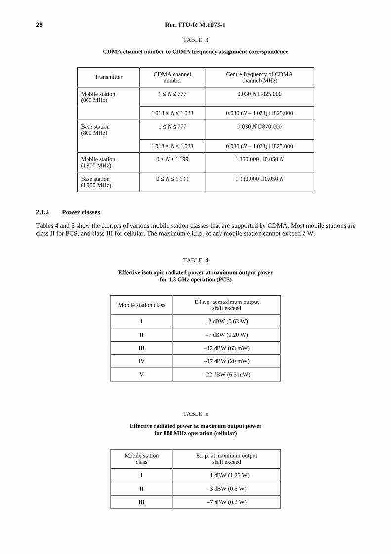
28 Rec. ITU-R M.1073-1
TABLE 3
CDMA channel number to CDMA frequency assignment correspondence
2.1.2 Power classes
Tables 4 and 5 show the e.i.r.p.s of various mobile station classes that are supported by CDMA. Most mobile stations areclass II for PCS, and class III for cellular. The maximum e.i.r.p. of any mobile station cannot exceed 2 W.
TABLE 4
Effective isotropic radiated power at maximum output powerfor 1.8 GHz operation (PCS)
TABLE 5
Effective radiated power at maximum output powerfor 800 MHz operation (cellular)
Transmitter CDMA channelnumber
Centre frequency of CDMAchannel (MHz)
Mobile station(800 MHz)
1 ≤ N ≤ 777 0.030 N + 825.000
1 013 ≤ N ≤ 1 023 0.030 (N – 1 023) + 825.000
Base station(800 MHz)
1 ≤ N ≤ 777 0.030 N + 870.000
1 013 ≤ N ≤ 1 023 0.030 (N – 1 023) + 825.000
Mobile station(1 900 MHz)
0 ≤ N ≤ 1 199 1 850.000 + 0.050 N
Base station(1 900 MHz)
0 ≤ N ≤ 1 199 1 930.000 + 0.050 N
Mobile station classE.i.r.p. at maximum output
shall exceed
I –2 dBW (0.63 W)
II –7 dBW (0.20 W)
III –12 dBW (63 mW)
IV –17 dBW (20 mW)
V –22 dBW (6.3 mW)
Mobile stationclass
E.r.p. at maximum outputshall exceed
I 1 dBW (1.25 W)
II –3 dBW (0.5 W)
III –7 dBW (0.2 W)
Rec. ITU-R M.1073-1 29
2.2 Forward link
2.2.1 RF interface
2.2.1.1 Data modulation
Data modulation on the forward link is coherent BPSK at a symbol rate of 19.2 kbit/s.
2.2.1.2 Spreading modulation
The forward link symbol stream is added, modulo 2, to an orthogonal cover sequence used for channelization, and thenQPSK-spread by a 1.2288 MHz pseudo-noise sequence with a period of 32 768 chips. The radiated waveform is tightlyband-limited to a bandwidth of 1.25 MHz. Distant base stations are distinguished from one another by the relative phasesof their pilot PN sequences.
2.2.2 Channel structure
The forward link is channelized by adding a cover sequence to each channel. The cover sequences have a period equal tothe symbol duration, and are mutually orthogonal. The orthogonality of the cover sequences permits separation of64 logical channels at the mobile station receiver. There are three types of overhead channels: pilot, sync, and paging.The remaining channels are available for traffic.
2.2.2.1 Pilot channel
The pilot channel is spread but otherwise unmodulated. It serves as a phase reference for coherent demodulation of theother 63 channels. It is also used as a search target for acquisition of new base stations as the mobile stations move fromone coverage area to another.
2.2.2.2 Sync channel
The sync channel carries information which permits the mobile stations to determine system time and pilot offset of thebase station during initial acquisition of the system. The sync channel data rate is 1 200 bit/s.
2.2.2.3 Paging channels
Each base station has one or more paging channels. The paging channels carry information for mobile stations for whichthere are not a call. This includes system parameters, broadcast short messages, mobile directed short messages, pages,and acknowledgements for messages sent on the access channel.
The data rate on the paging channels is 4 800 or 9 600 bit/s, at the discretion of the operator. The paging channelssupport mobile stations that can operate in both the slotted mode and the non-slotted mode. Mobile stations operating inthe slotted mode periodically power up to receive pages, short messages, or other information directed to them. Themobile station can select the interval in which it powers up. This can be from 1.28 s to 163.84 s.
2.2.2.4 Traffic channels
Traffic channels carry coded speech and other traffic. Variable rate traffic on the forward link reduces the mutualinterference between channels. Two sets of data rates are supported, Rate Set 1 and Rate Set 2. Data rates of 9 600,4 800, 2 400, and 1 200 bit/s are available frame-by-frame on the traffic channel for Rate Set 1. Data rates of 14 400,7 200, 3 600, and 1 800 bit/s are available frame-by-frame on the traffic channel for Rate Set 2. These rates support both8.5 kbit/s and 13.3 kbit/s speech and data services.
2.2.3 Coding and interleaving
The forward link is convolutionally coded and block interleaved. The convolutional code has a constraint length of 9.The sync channel, the paging channels, and the forward traffic channel for Rate Set 1 have a convolutional code rateof 1/2. The forward traffic channel for Rate Set 2 has an effective code rate of 3/4. When at other than 9 600 or14 400 bit/s, code symbols are repeated to provide diversity.
30 Rec. ITU-R M.1073-1
The sync channel uses a block interleaver spanning 26.666... ms, which is equivalent to 128 modulation symbols at thesymbol rate of 4 800 s/s. The forward traffic and paging channels use an identical block interleaver spanning 20 ms,which is equivalent to 384 modulation symbols at the modulation rate of 19 200 s/s.
Each frame with Rate Set 2 and the 9 600 and 4 800 bit/s frames of Rate Set 1 include a frame quality indicator. Thisframe quality indicator is a CRC.
2.2.4 Reverse-link power control
A power control sub-channel is continuously transmitted on the forward traffic channel. The sub-channel transmits onebit (either “0” or “1”) every 1.25 ms which adjusts the reverse link transmit power incrementally by ± 1 dB.
2.2.5 Forward link power control
Rate Set 2 supports a one bit-per-frame power control mechanism in which the mobile station indicates whether theframe was correctly or incorrectly received. The base station can use this one bit-per-frame power control stream toadjust the transmitted power on the forward traffic channel directed to the mobile station. Both Rate Set 1 and Rate Set 2support signalling messaging to convey forward link error statistics which can be used to adjust the forward linktransmitted power.
2.3 Reverse link
2.3.1 RF interface
2.3.1.1 Data modulation
Data modulation on the reverse link is 64-ary orthogonal, using Walsh codes. The symbol rate is 4 800 s/s.
2.3.1.2 Spreading modulation
The reverse link symbol stream is added, modulo 2, to a 1.2288 MHz cover sequence used for channelization, and thenOQPSK-spread using a pair of 1.2288 MHz pseudo-noise sequences with a period of 32 768 chips. This is the samesequence as the pilot PN sequence used by the forward link. The reverse cover sequence (“long code”) is a unique phaseof a 42-bit maximal length linear feedback shift register sequence. The radiated waveform is tightly band-limited to abandwidth of 1.25 MHz.
2.3.2 Channel structure
Channelization of the reverse link is accomplished by assigning each mobile station a unique phase of the long code touse for covering its traffic transmissions. There are also pre-defined phases for common access channels. Unlike theforward link, the reverse link cover sequences are not orthogonal.
2.3.2.1 Access channels
Access channels have pre-defined long code phases. They are used by the mobile stations to communicate with the basestation when the mobile station is not assigned to a traffic channel. Typically, this is to respond to a page, to originate acall, or to perform a registration. The access channel data rate is 4 800 bit/s.
2.3.2.2 Traffic channels
Traffic channels carry coded speech, or other traffic. Variable rate traffic on the reverselink reduces the mutualinterference between channels. Two sets of data rates are supported, Rate Set 1 and Rate Set 2. Data rates of 9 600,4 800, 2 400, and 1 200 bit/s are available frame-by-frame on traffic channels for Rate Set 1. Data rates of 14 400, 7 200,3 600, and 1 800 bit/s are available frame-by-frame on the traffic channel for Rate Set 2. The rate can change every20 ms. These rates support both 8.5 kbit/s and 13.3 kbit/s speech and data services.
Rec. ITU-R M.1073-1 31
2.3.3 Coding and interleaving
The reverse link is convolutionally coded and block interleaved. The convolutional code has a constraint length of 9.The reverse traffic channel for Rate Set 1 has a convolutional code rate of 1/3. The reverse traffic channel for Rate Set 2has an effective code rate of 1/2.
The reverse traffic channel uses a block interleaver spanning 20 ms, which is equivalent to 576 code symbols. Eachframe with Rate Set 2 and the 9 600 and 4 800 bit/s frames of Rate Set 1 include a frame quality indicator. This framequality indicator is a CRC. No frame quality indicator is used for the 2 400 and 1 200 bit/s transmission rates of RateSet 1.
2.3.4 Reverse link power control
The power transmitted by the mobile station is regulated to be near the minimum required for adequate error rateperformance. The radiated power is estimated from the received base station power, and is corrected by the bitsconveyed by the received closed loop power control sub-channel.
2.4 Associated signalling channel
Signalling between the mobile and base stations, after the transition to the traffic channel, is accomplished by“blank-and-burst” or “dim-and-burst” in the traffic channel. Blank-and-burst pre-empts one or more traffic frames andsubstitutes the signalling message. Dim-and-burst is similar, except the speech coder is informed that it may not usefull-rate. A full-rate frame thus consists of the half-rate or lower rate speech data and a half frame of signalling data. Thedim-and-burst method has less impact on voice quality. In both cases the receiving speech codec is notified that theframe was pre-empted, and it can take mitigating actions, possibly different than those it would take when the frame is inerror.
2.5 Handover
2.5.1 Soft handover
The system supports seamless soft handover. This is accomplished by two or more base stations radiating the outputtraffic for the mobile station. The mobile station combines the signal from these base stations. This provides spatialdiversity, thus improving quality and coverage; furthermore, soft handovers are undetectable by the users.
2.5.2 Hard handover
Hard handover is supported for instances when the mobile station is transferred between disjoint active sets, differentCDMA frequency assignments, or different frame offsets. Hard handovers are also supported to transfer a mobile stationfrom CDMA PCS to CDMA cellular and analogue cellular.
2.6 Registration and mobility management
Mobility management is supported by nine operator-selectable registration mechanisms. The nine types of registra-tion are:
– Power up : the mobile station registers when it is turned on.
– Power down : the mobile station registers when it is turned off.
– Time based : the mobile station registers when a timer expires.
– Distance based : the mobile station registers when the distance between the current base station and the last basestation in which it last registered exceeds a threshold.
– Zone based : the mobile station registers when it enters a new zone.
– Parameter change : the mobile station registers when certain of its stored parameters change.
– Ordered : the mobile station registers when requested by the base station.
– Traffic channel : the base station can interrogate a mobile station that has been assigned to a traffic channel, therebyaccomplishing a registration.
– Implicit : any origination or page response constitutes an implied registration.
32 Rec. ITU-R M.1073-1
2.7 Security features
Both global and unique challenge-response authentication procedures are available to prevent various types ofover-the-air service fraud. All traffic channel transmissions can be protected by the private long code. Higher protectionis obtained by encrypting certain sensitive message fields. This protects items such as subscriber-entered credit cardnumbers, PINs, etc.
2.8 Mobile station identification
The electronic serial number (ESN) is used to uniquely identify a mobile station to any PCS system. The ESN has 32,40, 48 or 56 bits.
The user subscription is identified by the ITU-T Recommendation E.212 International Mobile Station Identity (IMSI).The IMSI consists of up to 15 numerical characters (0-9). The first three digits of the IMSI are the mobile countrycode (MCC) and the remaining digits are the national mobile station identity (NMSI).
The mobile station can also be assigned a temporary mobile station identity (TMSI). The TMSI is used to hide theidentity of the user. It also allows for shorter addressing. The TMSI consists of a TMSI code and TMSI zone. The TMSIis assigned locally. The TMSI zone provides the identity of the network element which assigned the TMSI code.
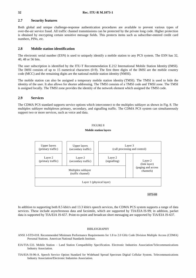
2.9 Services
The CDMA PCS standard supports service options which interconnect to the multiplex sublayer as shown in Fig. 8. Themultiplex sublayer multiplexes primary, secondary, and signalling traffic. The CDMA PCS system can simultaneouslysupport two or more services, such as voice and data.
1073-08
FIGURE 8
Mobile station layers
Upper layers(primary traffic)
Upper layers(secondary traffic)
Layer 2(primary traffic)
Layer 2(secondary traffic)
Layer 2(signalling)
Layer 3 (call processing and control)
Layer 2(link layer)
(paging and accesschannels)Multiplex sublayer
(traffic channel)
Layer 1 (physical layer)
FIGURE 8/1073...[D08] = 6.5 CM
In addition to supporting both 8.5 kbit/s and 13.3 kbit/s speech services, the CDMA PCS system supports a range of dataservices. These include asynchronous data and facsimile, which are supported by TIA/EIA IS-99; in addition, packetdata is supported by TIA/EIA IS-657. Point-to-point and broadcast short messaging are supported by TIA/EIA IS-637.
BIBLIOGRAPHY
ANSI J-STD-018. Recommended Minimum Performance Requirements for 1.8 to 2.0 GHz Code Division Multiple Access (CDMA)Personal Stations. American National Standards Institute.
EIA/TIA-533. Mobile Station – Land Station Compatibility Specification. Electronic Industries Association/TelecommunicationsIndustry Association.
TIA/EIA IS-96-A. Speech Service Option Standard for Wideband Spread Spectrum Digital Cellular System. TelecommunicationsIndustry Association/Electronic Industries Association.
Rec. ITU-R M.1073-1 33
ANNEX 6
General description of the composite CDMA/TDMA system
1 Introduction
This Trial Use Standard J-STD-017/Interim Standard IS-661 (the Standard or document) has been produced by theComposite CDMA/TDMA/FDMA Technical Ad Hoc Group (TAG) of the Joint Technical Committee on WirelessAccess (JTC). This Trial Use/Interim Standard describes the system design which was pioneered by the OmnipointCorporation for use in the United States Personal Communications Services (PCS) frequency bands. This standardcovers the system implementation and operation in the 1 850 to 1 990 MHz licensed frequency bands, within the publicswitched telecommunications network (PSTN).
2 Technical overview
The composite CDMA/TDMA (CCT) system provides an architecture that is optimized for PCS, utilizing specificbenefits of FDMA, TDMA, and CDMA technologies to provide multiple user access to the PCS network.
The system employs direct sequence spread spectrum (DSSS) with TDMA, FDMA, and CDMA for PCS digitalcommunications RF links. The use of the combined technologies will:
– help mitigate the PCS link performance degradation caused by multipath propagation conditions experienced intypical mobile PCS environments.
– help mitigate problems of interference with OFS users near the PCS operating area.
The technology can:
– accommodate the full range of mobile handover conditions, including those at freeway speed;
– permit use of a bandwidth efficient frequency reuse factor of N = 3. Up to 32 simultaneous users per RF channelcan be accommodated, and a variable data rate up to 256 kbit/s (full-duplex) is available to any user.
2.1 Air interface description
2.2 Transmitter power output characteristics
2.2.1 Mobile station (MS)
The peak effective isotropic radiated power (e.i.r.p.) of the MS is a nominal 1 W. The average power delivered to theantenna is less than 10 mW for each 8 kbit/s time-slot, permitting long durations between MS battery recharges. Theconstant envelope characteristic of the modulation technique permits use of an efficient non-linear output amplifierwhich further reduces battery drain.
2.2.2 Base station (BS)
The FCC rules permit up to 1 640 W peak e.i.r.p. per RF channel for PCS BSs. The maximum BS conducted RF poweroutput to its antenna is 2 W.
34 Rec. ITU-R M.1073-1
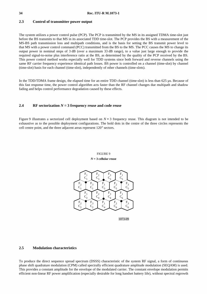
2.3 Control of transmitter power output
The system utilizes a power control pulse (PCP). The PCP is transmitted by the MS in its assigned TDMA time-slot justbefore the BS transmits to that MS in its associated TDD time-slot. The PCP provides the BS with a measurement of theMS-BS path transmission loss and multipath conditions, and is the basis for setting the BS transmit power level tothat MS with a power control command (PCC) transmitted from the BS to the MS. The PCC causes the MS to change itsoutput power in nominal steps of 3 dB (over a maximum 33 dB range), to a value just large enough to provide therequired signal-to-noise plus interference ratio at the BS, as determined by the quality of the PCP received by the BS.This power control method works especially well for TDD systems since both forward and reverse channels using thesame RF carrier frequency experience identical path losses. BS power is controlled on a channel (time-slot) by channel(time-slot) basis for each channel (time-slot), independently of other channels (time-slots).
In the TDD/TDMA frame design, the elapsed time for an entire TDD channel (time-slot) is less than 625 µs. Because ofthis fast response time, the power control algorithm acts faster than the RF channel changes due multipath and shadowfading and helps control performance degradation caused by these effects.
2.4 RF sectorization N = 3 frequency reuse and code reuse
Figure 9 illustrates a sectorized cell deployment based on N = 3 frequency reuse. This diagram is not intended to beexhaustive as to the possible deployment configurations. The bold dots in the centre of the three circles represents thecell centre point, and the three adjacent areas represent 120° sectors.
1073-09
F1C1
F2C3
F3C3
F1C5
F2C1
F3C1
F1C3
F2C5
F3C5
F1C2
F2C4
F3C4
F1C6
F2C2
F3C2
F1C4
F2C6
F3C6
FIGURE 9
N = 3 cellular reuse
FIGURE 9/1073...[D09] = 6 CM
2.5 Modulation characteristics
To produce the direct sequence spread spectrum (DSSS) characteristic of the system RF signal, a form of continuousphase shift quadrature modulation (CPM) called spectrally efficient quadrature amplitude modulation (SEQAM) is used.This provides a constant amplitude for the envelope of the modulated carrier. The constant envelope modulation permitsefficient non-linear RF power amplification (especially desirable for long handset battery life), without spectral regrowth
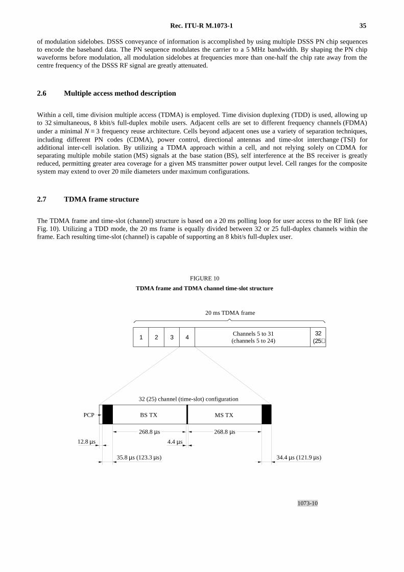
Rec. ITU-R M.1073-1 35
of modulation sidelobes. DSSS conveyance of information is accomplished by using multiple DSSS PN chip sequencesto encode the baseband data. The PN sequence modulates the carrier to a 5 MHz bandwidth. By shaping the PN chipwaveforms before modulation, all modulation sidelobes at frequencies more than one-half the chip rate away from thecentre frequency of the DSSS RF signal are greatly attenuated.
2.6 Multiple access method description
Within a cell, time division multiple access (TDMA) is employed. Time division duplexing (TDD) is used, allowing upto 32 simultaneous, 8 kbit/s full-duplex mobile users. Adjacent cells are set to different frequency channels (FDMA)under a minimal N = 3 frequency reuse architecture. Cells beyond adjacent ones use a variety of separation techniques,including different PN codes (CDMA), power control, directional antennas and time-slot interchange (TSI) foradditional inter-cell isolation. By utilizing a TDMA approach within a cell, and not relying solely on CDMA forseparating multiple mobile station (MS) signals at the base station (BS), self interference at the BS receiver is greatlyreduced, permitting greater area coverage for a given MS transmitter power output level. Cell ranges for the compositesystem may extend to over 20 mile diameters under maximum configurations.
2.7 TDMA frame structure
The TDMA frame and time-slot (channel) structure is based on a 20 ms polling loop for user access to the RF link (seeFig. 10). Utilizing a TDD mode, the 20 ms frame is equally divided between 32 or 25 full-duplex channels within theframe. Each resulting time-slot (channel) is capable of supporting an 8 kbit/s full-duplex user.
1073-10
1 2 3 4 32(25)
FIGURE 10
TDMA frame and TDMA channel time-slot structure
20 ms TDMA frame
Channels 5 to 31(channels 5 to 24)
PCP MS TXBS TX
32 (25) channel (time-slot) configuration
35.8 µs (123.3 µs)
12.8 µs
268.8 µs
4.4 µs
268.8 µs
34.4 µs (121.9 µs)
FIGURE 10 [1073-10]= 11 CM
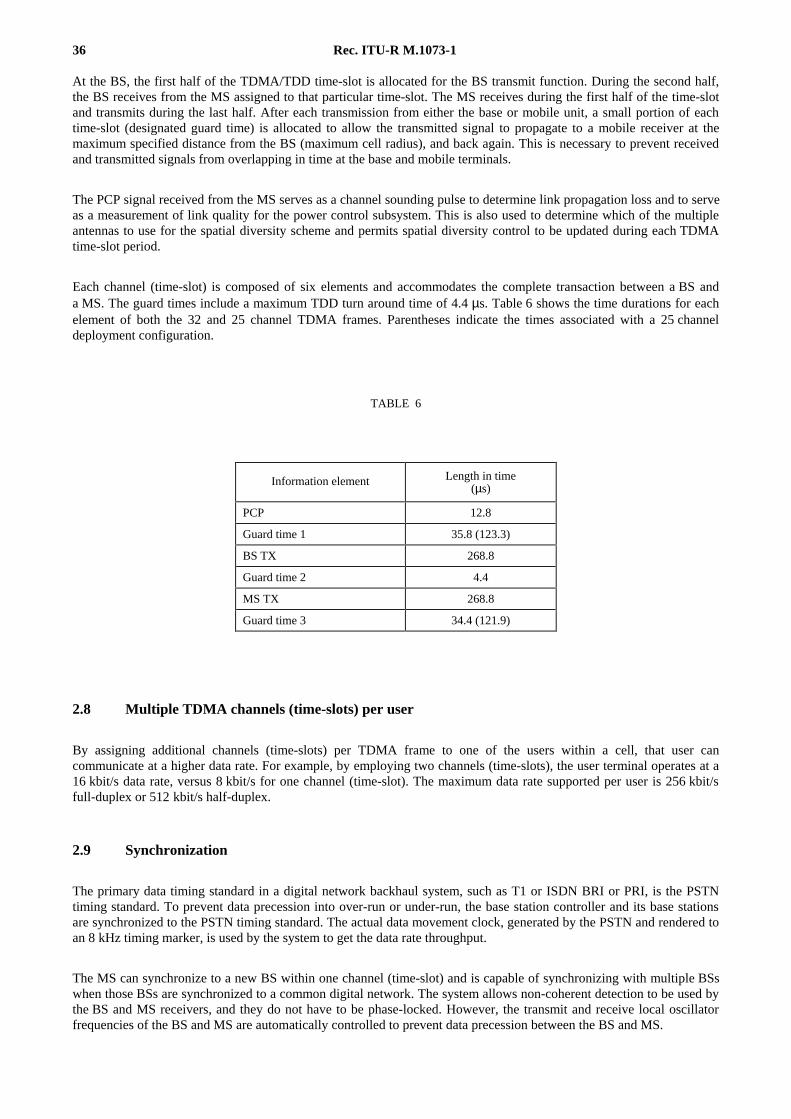
36 Rec. ITU-R M.1073-1
At the BS, the first half of the TDMA/TDD time-slot is allocated for the BS transmit function. During the second half,the BS receives from the MS assigned to that particular time-slot. The MS receives during the first half of the time-slotand transmits during the last half. After each transmission from either the base or mobile unit, a small portion of eachtime-slot (designated guard time) is allocated to allow the transmitted signal to propagate to a mobile receiver at themaximum specified distance from the BS (maximum cell radius), and back again. This is necessary to prevent receivedand transmitted signals from overlapping in time at the base and mobile terminals.
The PCP signal received from the MS serves as a channel sounding pulse to determine link propagation loss and to serveas a measurement of link quality for the power control subsystem. This is also used to determine which of the multipleantennas to use for the spatial diversity scheme and permits spatial diversity control to be updated during each TDMAtime-slot period.
Each channel (time-slot) is composed of six elements and accommodates the complete transaction between a BS anda MS. The guard times include a maximum TDD turn around time of 4.4 µs. Table 6 shows the time durations for eachelement of both the 32 and 25 channel TDMA frames. Parentheses indicate the times associated with a 25 channeldeployment configuration.
TABLE 6
2.8 Multiple TDMA channels (time-slots) per user
By assigning additional channels (time-slots) per TDMA frame to one of the users within a cell, that user cancommunicate at a higher data rate. For example, by employing two channels (time-slots), the user terminal operates at a16 kbit/s data rate, versus 8 kbit/s for one channel (time-slot). The maximum data rate supported per user is 256 kbit/sfull-duplex or 512 kbit/s half-duplex.
2.9 Synchronization
The primary data timing standard in a digital network backhaul system, such as T1 or ISDN BRI or PRI, is the PSTNtiming standard. To prevent data precession into over-run or under-run, the base station controller and its base stationsare synchronized to the PSTN timing standard. The actual data movement clock, generated by the PSTN and rendered toan 8 kHz timing marker, is used by the system to get the data rate throughput.
The MS can synchronize to a new BS within one channel (time-slot) and is capable of synchronizing with multiple BSswhen those BSs are synchronized to a common digital network. The system allows non-coherent detection to be used bythe BS and MS receivers, and they do not have to be phase-locked. However, the transmit and receive local oscillatorfrequencies of the BS and MS are automatically controlled to prevent data precession between the BS and MS.
Information element Length in time(µs)
PCP 12.8
Guard time 1 35.8 (123.3)
BS TX 268.8
Guard time 2 4.4
MS TX 268.8
Guard time 3 34.4 (121.9)

Rec. ITU-R M.1073-1 37
2.10 Handover
Handover is required whenever the received signal level at a MS falls below an acceptable level. The System utilizes amobile station-controlled handover method.
For most handovers, the total time delay for the handover procedure, including re-establishment of bearer channeltraffic, is typically less than 10 ms. The maximum time is approximately 40 ms. Since under normal circumstances thedelay is less than one polling loop interval, bearer packets will continue to the MS with no interruption. Inter-clusterhandover or time-slot interchange (TSI) is partially dependent upon the delays inherent in the host PCSC, and arebeyond the scope of this general system description. Over-the-air delays for the inter-cluster handover are the same asabove, i.e., 10-40 ms. Break-before-make handovers typically take less than 250 ms.
1073-11
8
7
6
5
4
3
2
18 10 12 14 16 18 20 22 24 26
FIGURE 11
Rapid hand-off capability enhances overall coverage statistics
Base station antenna gain (dB dipole)
Con
tour
rad
ius
(mil
es)
COST 231 propagation model, base antenna at 50 m, mobile at 1.5 m9 m roof height. 8 dB log normal standard deviation.
50% contour
75% contour
90% contour
90% overallcoverage
99% overallcoverage
Handset transmits 300 mW peak into 0 dB dipole antenna.Base station sensitivity is – 100 dBm.
FIGURE 11 [1073-11]= 12 CM
2.11 Network implementation
The CCT system is designed around an object-based software architecture which allows for flexibility in interconnectionto the PSTN, AIN and GSM network infrastructures and IS-41 network interconnection. This approach providesthe PCS operator with flexibility to deploy whatever network infrastructure meets the appropriate business goals andservice descriptions desired.
2.12 Feature support
Features and services typically found in the wireline environment such as voicemail, call hold, call waiting, caller ID,three-way calling, etc. as well as wireless services like short message service, smart card and over-the-air programmingare supported by the CCT system.
38 Rec. ITU-R M.1073-1
2.13 International Mobile Telecommunications-2000 (IMT-2000) evolution
The composite CDMA/TDMA technology was developed with the flexibility to evolve to a more enhanced offering.Data rates to be facilitated over the air interface will be improved to approach the IMT-2000 goal of 2 Mbit/s. Inaddition, different frequency allocations will be accommodated by utilizing multiple air interface options whilemaintaining the same channel and voice coding as well as over-the-air signalling. This will allow full feature delivery inmultiple implementation environments and frequency allocations.
BIBLIOGRAPHY
EIA/TIA-553. Mobile Station – Land Station Compatibility Specification. Electronic Industries Association/TelecommunicationsIndustry Association.
TIA/EIA IS-96-A. Speech Service Option Standard for Wideband Spread Spectrum Digital Cellular System. TelecommunicationsIndustry Association/Electronic Industries Association.
TIA/EIA IS-99. Data Services Option Standard for Wideband Spread Spectrum Digital Cellular System.
TIA/EIA IS-634. MSC-BS Interface for Public 800 MHz.
TIA/EIA IS-637. Short Message Services for Wideband Spread Spectrum Digital Cellular Systems.
TIA/EIA IS-651. SS7-based A-Interface.
TIA/EIA IS-657. Packet Data Services for Wideband Spread Spectrum Digital Cellular Systems.
ANNEX 7
General description of the North American “W-CDMA(wideband code division multiple access)”
1 Introduction
1.1 Functional overview
The North American wideband CDMA (W-CDMA) PCS system provides for voice, voiceband data, transparent data,and non-transparent data services through call control, radio resource management, and mobility management. Thesystem also supports secure voice and data services using authentication and privacy procedures. For details, seeEIA/TIA IS-665 and ANSI J-STD-015 (Trial Use) Standard.
W-CDMA utilizes a CDMA method as the air interface access method. At the transmitter side, the information signal isdirect sequence spread using a unique code produced by pseudorandom and Hadamard codes. On the receiving side, theinformation signal is despread using the same codes. Frequency division duplex (FDD) is used with an 80 MHz duplexspacing. The personal station transmit frequencies are between 1 850 and 1 910 MHz, and the base station transmitfrequencies are between 1 930 and 1 990 MHz. The W-CDMA standard supports RF bandwidths of 5 MHz, 10 MHz and15 MHz. Each of these bandwidths supports data rate choices of 16, 32 and 64 kbit/s.
An advanced ADPCM (COM101+) voice coder at 32 kbit/s is used to provide toll quality speech, even when in a severeradio environment. It is superior in performance to these ITU standard speech coders: PCM (G.711), ADPCM (G.721),and LD-CELP (G.728).
Rec. ITU-R M.1073-1 39
W-CDMA has a flexible interface for accommodating various switching systems. It is able to interconnect withswitching systems using signalling system (SS) No. 7. Channel assignment, handover control, call control, registration,authentication, and OAM&P (operation, administration, maintenance & provisioning) are managed through theTelecommunications Management Network (TMN).
By using wideband spreading, W-CDMA achieves high quality speech, high data rate, and robust resistance to multipathfading. The processing gain inherent in wideband spreading overcomes the interference among users in the samebandwidth. In addition to wideband spreading, W-CDMA utilizes open and closed loop power control, forward errorcorrection, interleaving, multipath combining, and interference cancellation to obtain higher system capacity comparedto other PCS standards. Details of the supporting network architecture are described in Appendix 1, and the system forexchanging call detail subscriber usage information is in Appendix 2.
1.2 System configuration
Figure 12 shows a generic model of a PCS system based on W-CDMA. In this figure, the base station controller may beincluded in each base station, in the personal switching centre, or as a separate entity.
2 Technical characteristics
2.1 Forward link
2.1.1 RF interface
2.1.1.1 Data modulation
Data modulation on the forward link is coherent QPSK at a symbol rate of 64 kbit/s.
2.1.1.2 Spreading modulation
BPSK spreading modulation is used for inphase (I) and quadrature phase (Q) channels by pseudorandom and Hadamardsequences with a chip rate of either 4.096 or 8.192, or 12.288 Mchip/s and a period of 20 ms.
The radiated waveform is tightly band-limited to a bandwidth of either 4.1, 8.2, or 12.3 MHz. Base stations aredistinguished from one to another by the relative phases of their spreading sequences.
2.1.2 Channel structure
The forward link is composed of pilot, sync, paging, and traffic channels. Channelization of the forward link isaccomplished by adding Hadamard and pseudorandom sequences to each channel. The pseudorandom and Hadamardsequences have the same chip rate.
Hadamard codes are used to provide orthogonality for each channel, which enables the separation of 64, 128, or192 channels at the personal station receiver.
2.1.2.1 Pilot channel
The pilot channel is associated with each base station as an unique channel. The pilot channel is spread but unmodulated.It serves as a phase reference for coherent demodulation of the other channels. It is also used as a search target foracquisition of a new base station when the personal station moves from one coverage area to another.
2.1.2.2 Sync channel
The sync channel carries information which permits the personal station to determine system time and pilot offset of thebase station in preparation for system access. The data rate on the sync channel is 16 kbit/s.
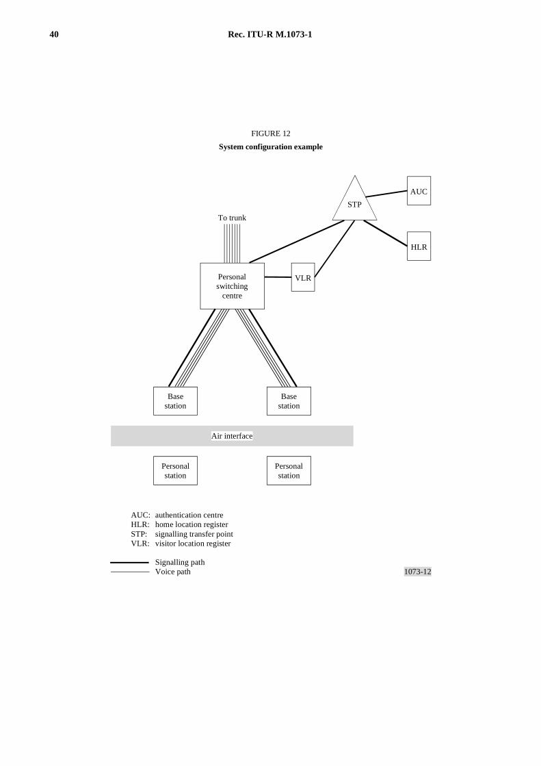
40 Rec. ITU-R M.1073-1
1073-12
FIGURE 12
System configuration example
Basestation
Personalstation
Personalswitching
centre
Basestation
Air interface
To trunk
Personalstation
authentication centrehome location registersignalling transfer pointvisitor location register
Signalling pathVoice path
HLR
AUC
VLR
STP
AUC:HLR:STP:VLR:
FIGURE 12 [1073-12]= 16.5 CM
Rec. ITU-R M.1073-1 41
2.1.2.3 Paging channels
One or more paging channels are associated with each base station. The paging channels broadcast the identifications ofpersonal stations for which there are incoming calls. Personal stations that receive their identifications via the pagingchannel respond to the base station via an access channel. The data rate of the paging channels is 16 kbit/s.
2.1.2.4 Traffic channels
The traffic channels carry coded speech or other information. Data rates of 64, 32, and 16 kbit/s are availableframe-by-frame on the traffic channel. The rate variation is achieved by the repetition of symbols with the energy per bitkept constant.
2.1.3 Coding and interleaving
The forward link is convolutionally coded and block interleaved. The coding is rate 1/2 with a constraint length of 9.The interleaving span is 5 ms on the sync and paging channels. The interleaving span on the traffic channel is 5 ms withoptions of 10 or 20 ms.
The sync and paging channel messages are protected by a 32-bit cyclic redundancy code (CRC), which can be used bythe receiver to detect decoding failures.
2.1.4 Reverse link power control bit stream
The forward traffic channels are punctured at 2 kbit/s for independent closed loop power control of each personalstation. Either 2 or 4, or 8 symbols per power control bit are used, respectively, at 64, 32 or 16 kbit/s traffic data rates.The power control bit stream is uncoded.
2.2 Reverse link
2.2.1 RF interface
2.2.1.1 Data modulation
Data modulation on the reverse link is coherent QPSK at a symbol rate of 64 ks/s.
2.2.1.2 Spreading modulation
BPSK spreading modulation is used for inphase (I) and quadrature phase (Q) channels by pseudorandom and Hadamardsequences with chip rates of 4.096, 8.192 or 12.288 Mchip/s and a period of 20 ms.
The radiated waveform is tightly band limited to a bandwidth of 4.1, 8.2, or 12.3 MHz. Base stations are distinguishedfrom one another by the relative phases of their spreading sequences.
2.2.2 Channel structure
The reverse link is composed of pilot, access, traffic, and signalling channels. Channelization of the reverse link isaccomplished by adding pseudorandom and Hadamard sequences. The pseudorandom and Hadamard sequences have thesame chip rate.
Hadamard codes are used to provide orthogonality among the pilot, traffic and signalling channels of each personalstation.
2.2.2.1 Pilot channel
The pilot channel is associated with the traffic channel of the personal station. The pilot channel is spread butunmodulated. It serves as a phase reference for coherent demodulation of the other channels. It is also used as a searchtarget for acquisition of a new base station when the personal station moves from one coverage area to another.
42 Rec. ITU-R M.1073-1
2.2.2.2 Access channel
The access channel is used either to respond to the base station paging channels or to originate a call, or to perform aregistration. The access channel data rate is 16 kbit/s.
2.2.2.3 Traffic channel
The traffic channel carries coded speech or other traffic. Data rates of 64, 32, and 16 kbit/s are available frame-by-frameon traffic channel. The rate variation is achieved by repetition of symbols.
2.2.2.4 Signalling channel
The signalling channel is associated with the traffic channel of the personal station. The signalling channel rate iseither 4 or 4, or 2 kbit/s, respectively, for data rates of 64, 32, or 16 kbit/s.
2.2.3 Coding and interleaving
Convolutional coding on the reverse link is rate 1/2, constraint length 9. The traffic channel is interleaved with 5 ms oroptionally either 10 or 20 ms. The signalling channel is block interleaved with 5 ms.
2.2.4 Forward link power control
The power transmitted by the personal station is regulated to be near the minimum required for adequate error rateperformance. The radiated power is determined by the received base station power information via the signallingchannel.
2.3 Handover operation
The base station supports either of the following two handover procedures, which may be selected by the serviceprovider.
Type A handover : Assume the personal station is in the active state where it is simultaneously receiving a pilot channeland a traffic channel from a designated serving base station. The Type A handover method first establishes a pilotchannel between the personal station and a designated target base station. In this condition the personal station issimultaneously receiving pilot channels from both serving and target base stations. Upon command, the traffic channelfrom the serving base station is switched to the target base station. The personal station now receives the traffic channelfrom the target base station. The personal station then disconnects the serving base station pilot, and the handover iscompleted.
Type B handover : A target base station initiates communications with the personal station without interrupting thecommunication with both serving base stations. The personal station provides diversity combining of forward trafficchannels from the serving and target base stations. Upon command, the traffic channel from the serving base station isdisconnected, and the handover is completed.
2.4 Speech coding and voiceband data transmission
A robust 32 kbit/s ADPCM speech coder (COM101+) is used for W-CDMA. The following services are implemented:
– toll quality voice for speech services,
– voiceband data rate up to 14.4 kbit/s,
– 9.6 kbit/s G3 FAX.
Figure 13 shows the result of comparison among these speech coding methods: COM101+, PCM (G.711),ADPCM (G.721), and LD-CELP (G.728).
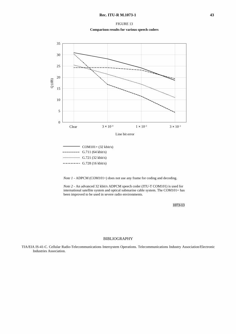
Rec. ITU-R M.1073-1 43
1073-13
35
30
25
20
15
10
5
03 × 10–4 1 × 10⁻³ 3 × 10⁻³
COM101+ (32 kbit/s)
G.711 (64 kbit/s)
G.728 (16 kbit/s)
G.721 (32 kbit/s)
Q (
dB)
FIGURE 13
Comparison results for various speech coders
Note 1 - ADPCM (COM101+) does not use any frame for coding and decoding.
Note 2 - An advanced 32 kbit/s ADPCM speech coder (ITU-T COM101) is used for international satellite system and optical submarine cable system. The COM101+ hasbeen improved to be used in severe radio environments.
Line bit error
Clear
FIGURE 13/1073...[1073-13] = 3 CM
BIBLIOGRAPHY
TIA/EIA IS-41-C. Cellular Radio-Telecommunications Intersystem Operations. Telecommunications Industry Association/ElectronicIndustries Association.
44 Rec. ITU-R M.1073-1
ANNEX 8
General description of the personal accesscommunications system (PACS)
1 Introduction
Personal access communications system (PACS) is a common air interface for low to intermediate tier PCS radio access.The characteristics of PACS differ from those of other PCS radio air interface technologies in several respects. It isintended for both outdoor low tier and indoor venues and has both a frequency division duplex (FDD) mode and a timedivision duplex (TDD) mode. It offers both circuit and packet mode access embedded in the protocol. The intendedapplications include:
– moderate mobility (up to 65 km/h) outdoor (FDD mode recommended) such as urban traffic,
– fixed wireless access,
– low mobility indoor (up to 30 km/h) such as wireless PBX, wireless Centrex, wireless keysets or cordless telephony(TDD or FDD mode acceptable).
PACS offers a common air interface which is applicable to a wide range of venues and environments and which cansupport interoperability between both public and private access. PACS has been designed for easy integration into anexisting PSTN and maximizes the use of existing network elements.
The fixed wireless access (FWA) application pertains to situations where a wireless drop connection may be preferable(for economic or other reasons) to a wireline connection. FWA subscriber units (SUs) provide a standard interface(e.g., RJ-11 jack) to the user allowing access from standard telephone equipment.
The PACS air interface is specified in:
– ANSI J-STD-014 Personal Access Communication System Air Interface Standard;
– ANSI J-STD-014A Personal Access Communication System Unlicensed – Version A Air Interface Standard;
– ANSI J-STD-014B Personal Access Communication System Unlicensed – Version B Air Interface Standard.
2 Services
The PACS air interface is designed to support voice, voiceband data, and digital data services along with the relatedintelligent network services. The system also supports emergency calls without subscriber registration.
2.1 Teleservices
Some of the services included as part of the PACS PCS air interface standard include an individual messaging service, acircuit mode data non-transparent and protected mode data service, a packet mode data service as well as an interleavedspeech/data service.
2.2 Supplementary services
The supplementary services that are available include: call forwarding, three-way calling, call waiting, call completion,advice of charge and call restriction. Since the PSTN can provide the infrastructure, many other AIN-basedsupplementary services can be easily provided to subscribers.
Rec. ITU-R M.1073-1 45
2.3 Security aspects
PACS has been designed to ensure a level of security consistent with that specified in TIA PN 3554, Vols. 1, 2 and 3,“Privacy and Authentication for Personal Communication Services”. Security features are provided to protect the accessto services and the privacy of user-related information. The following security features are implemented in PACS:
– subscriber identity confidentiality;
– subscriber identity authentication: it verifies that the subscriber identity sent by the SU is the one claimed (notduplicated or impersonated);
– user data confidentiality: it ensures that the user data including speech, transferred on the radio path cannot bedisclosed by unauthorized bodies;
– signalling information element confidentiality: all signalling information such as subscriber and equipmentidentities, directory numbers, etc., exchanged on the radio path cannot be used by unauthorized individuals orentities.
The SubID is the information which uniquely identifies the subscriber, and must be present and valid to allow operationof subscriber units.
Each SU has a unique identity that is implemented by the manufacturer called the electronic serial number.
PACS supports both public and private key authentication and privacy.
3 Overview of the system
The functional representation of the system architecture is shown in Fig. 14. The architecture consists of fixed orportable subscriber units (SUs) communicating through radio ports (RPs) that, typically, have wireline access via a radioport control unit (RPCU) and an access manager (AM) to the public switched telephone network (PSTN). The RPCU,AM and some network control functions may be further combined as a stand-alone unit or integrated into the PSTN.
The AM, in conjunction with the RPCU, facilitates aspects of radio access, such as automatic link transfer (ALT) for acall in progress moving from one RPCU to the next. The AM may be implemented in a switch adjunct, or itsfunctionality may be implemented in an advanced intelligent network service control function.
The switching network provides a variety of functions, including provisioning, performance management, capacitymanagement, etc.
The air interface specification is designed to be compatible with a number of different network architectures.
3.1 PACS and associated interfaces
The following interfaces are defined for the system:
– Interface A (the “air interface”) connects the SU and the RP.
– Interface P provides connectivity between the RPCU and its RPs. The protocols provided by layers 2 and 3 providefor interaction between the SU and the RPCU that, therefore, traverse interface P. Interface P also carries anembedded operations channel (EOC) that supports control functions between the RPCU and its RPs. The physicalinterconnection (layer 1) between the RPCU and its RPs may be implemented in any of several means.
– Interface C connects the RPCU to the Access Manager and the switch. Q.931 is one such interface standard.
4 Technical radio characteristics
PACS is a low power radio which uses π/4 DQPSK modulation. The downlink (RP-to-SU) uses time divisionmultiplexing (TDM) with a maximum of 800 mW RF transmit power. The uplink (SU-to-RP) uses time division
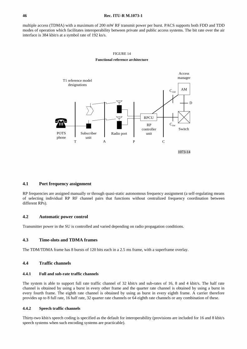
46 Rec. ITU-R M.1073-1
multiple access (TDMA) with a maximum of 200 mW RF transmit power per burst. PACS supports both FDD and TDDmodes of operation which facilitates interoperability between private and public access systems. The bit rate over the airinterface is 384 kbit/s at a symbol rate of 192 ks/s.
1073-14
D
RPCU
AM
T A P C
CAM
CSW
FIGURE 14
Functional reference architecture
Radio port
RPcontroller
unitSubscriberunit
POTSphone
Switch
T1 reference modeldesignations
Accessmanager
FIGURE 14 [1073-14]= 8 CM
4.1 Port frequency assignment
RP frequencies are assigned manually or through quasi-static autonomous frequency assignment (a self-regulating meansof selecting individual RP RF channel pairs that functions without centralized frequency coordination betweendifferent RPs).
4.2 Automatic power control
Transmitter power in the SU is controlled and varied depending on radio propagation conditions.
4.3 Time-slots and TDMA frames
The TDM/TDMA frame has 8 bursts of 120 bits each in a 2.5 ms frame, with a superframe overlay.
4.4 Traffic channels
4.4.1 Full and sub-rate traffic channels
The system is able to support full rate traffic channel of 32 kbit/s and sub-rates of 16, 8 and 4 kbit/s. The half ratechannel is obtained by using a burst in every other frame and the quarter rate channel is obtained by using a burst inevery fourth frame. The eighth rate channel is obtained by using as burst in every eighth frame. A carrier thereforeprovides up to 8 full rate, 16 half rate, 32 quarter rate channels or 64 eighth rate channels or any combination of these.
4.4.2 Speech traffic channels
Thirty-two kbit/s speech coding is specified as the default for interoperability (provisions are included for 16 and 8 kbit/sspeech systems when such encoding systems are practicable).
Rec. ITU-R M.1073-1 47
4.4.3 Data traffic channels
The circuit mode data service is a non-transparent mode, low latency data service in which data is enciphered for privacyand the data integrity is protected by error and flow control protocol, link access protocol for radio (LAPR). The roundtrip delay of the PACS air interface including the transport delay of the port-to-port controller interface and the RPCUprocessing time is on the order of a few tens of milliseconds. The data throughput in a 32 kbit/s channel is about28 kbit/s under extreme operating conditions. In addition, channel use can be aggregated to support higher data rates.
4.4.4 Packet channels
The packet mode data service is a shared contention-based RF packet protocol using a data sense multipleaccess (DSMA) contention mechanism. The downlink uses near-perfect scheduling. The basic structure of the packetchannel allows operation of subscriber units that are capable of operating on a single timeslot per TDMA frame as wellas subscriber units that achieve higher throughput and lower packet delays by using multiple timeslots per frame. Theprotocol allows both type of subscriber units to share the available packet bandwidth in a fair and equitable manner.
4.4.5 Voice/data capability
The interleaved speech/data service provides the ability to transmit both speech information and data information byusing a single 32 kbit/s time-slot. Data is transmitted during the quiet times between speech bursts. An advantage of thismode of operation is that handoffs are more reliable since only one 32 kbit/s channel need be set up to the new port.Data bursts are reliably delivered by the LAPR protocol and as with all PACS data services, enciphered for privacy.
4.4.6 Individual messaging service
The individual messaging service can deliver messages up to 16 Mbytes in length. The delivery is secure and protectedby an error and flow control protocol and the contents are ciphered to ensure privacy. The applications include textmessages, SMPT and MIME mail, Group III FAX imaging, as well as GIF, TIFF, JPEG and PICT imaging, PCM andADPCM encoded sound, MPEG video, and more.
4.5 System broadcast channel
One 16 or 8 kbit/s time-slot is allocated for system control information and is called the system broadcastchannel (SBC). The SBC is comprised of three logical channels called the system information channels, the alertingchannel and the priority request channel.
4.5.1 System information channel
The system information channel, or SIC, carries information relevant to all users, such as service provider identification,the encryption parameters, protocol parameters (such as counter and timer values), and so on. The SIC is broadcast in thedownlink of the SBC.
4.5.2 Alerting channel
The alerting channel, or AC, carries short codes that, when taken with the value of the alert phase, uniquely identifyregistered SUs in the registration area. The presence of a particular SU’s code signifies an incoming call for the SU. TheAC is multiplexed with the SIC into the downlink of the SBC. The alerting capacity of the FDD version of PACS is200 000 subscribers per alerting/registration area (ARA) with near-zero probability of alerting blocking during the busyhour. The corresponding alerting capacity of the TDD version of PACS is 80 000 subscribers per ARA.
The alerting channel is configured in a manner so as to allow an SU sleep mode with on/off duty cycle of 0.7%.
48 Rec. ITU-R M.1073-1
4.5.3 Priority access channel
The priority request channel, or PRC, provides for priority link access requests in the case of emergency when no trafficchannels are marked available for normal access. The priority request is sent by the SU on the uplink and theacknowledgement is sent by the RPCU on the downlink. Use of the PRC for access is limited to a few call types(i.e., emergency calls).
5 Operational characteristics
5.1 Channel selection
The SU is in the OFF state when it is not powered on and the SU moves to the OFF state from any other state uponbeing powered off. After being turned on, the SU enters the ACQUIRING state in which it scans frequencies to select asuitable RP signal.
Upon achieving phase lock with some RP, the SU enters the STANDBY state. The SU must synchronize to the bitstream, read the system information, and determine if registration is necessary. If registration is not required, the SUsynchronizes to its alert phase and listens for an indication of an incoming call. In the STANDBY state, the SU listens tothe SBC to acquire the latest system information.
If the SU determines that registration is necessary, or if the user is attempting to initiate a call, or if the SU wishes torespond to a broadcast alert (that is, a broadcast of incoming call notification), the SU seizes a traffic channel, and entersthe ACTIVE state.
The SU transitions to the STANDBY state upon release of the traffic channel at the end of a call. It transitions to theACQUIRING state upon loss of phase lock. If the SU transitions from the ACTIVE to the ACQUIRING state any call inprogress is held at the RPCU for an appropriate time until phase lock is achieved and the SU returns to the ACTIVEstate.
5.2 Registration (roaming)
The SU evaluates the received signal and initiates the registration procedure when necessary. Roaming is possiblebetween ARAs, and providers. Roaming is also possible between public and private systems.
5.3 Communication protocols
The communications protocols for PACS are divided into three layers. Layer one corresponds to the physical layer.Layer two is the link layer and the medium access layer. Layer three is the network layer. All layer three messages usethe positive acknowledgement at layer two for error control and flow control.
5.4 Call set-up
5.4.1 SU originated call set-up
Call origination is initiated by the SU which requests access on an available traffic channel to set up the radio resource.Next authentication is performed. Once link ciphering has been established, call set-up messages are exchanged.
5.4.2 SU terminated call set-up
After the SU receives a page from the network on the alerting channel, the same procedure as in § 5.4.1 is followed.
5.5 Automatic link transfer
In PACS, handover is called automatic link transfer (ALT). ALTs maintain the call in progress as the SU moves fromthe coverage area of one RP to that of another. In PACS, ALTs are controlled, directed and initiated by the SU and are
Rec. ITU-R M.1073-1 49
initiated on the new or preferred link. SU-directed ALTs result in fewer dropped calls, and are much faster thanconventional network directed handovers. Another important property of the ALT protocol allows call re-establishmentusing the same procedures as a normal link transfer even if the signal to the source or original RP is lost.
The network may deny SU-directed ALT requests. In addition, network directed ALT may be employed to meet networkmanagement requirements such as load shedding to relieve congestion.
BIBLIOGRAPHY
TIA/EIA IS-41-C. Cellular Radio-Telecommunications Intersystem Operations. Telecommunications Industry Association/ElectronicIndustries Association.
APPENDIX 1
Cellular intersystem operations
The Telecommunications Industry Association/Electronic Industries Association (TIA/EIA) IS-41 IntersystemOperations Standard was first introduced in February, 1988. This standard is in its fourth revision (IS-41-C). The intentof the standard is to provide the functionality necessary to support wireless access to the cellular and public switchingnetwork services and to support seamless roaming between different service providers using various vendor cellularsystems. The standard supports analogue and digital air interface technologies (e.g., AMPS, TDMA, CDMA,narrow-band AMPS).
IS-41-C performs these functions by providing operations and procedures which:
– autonomously detect the presence of a mobile subscriber in a visited system,
– authenticate a subscriber for service,
– authorize a subscriber for specific services,
– allow access to subscribed services while roaming,
– provide continuity of in-progress calls through the handoff (handover) process.
1 Functional overview
This section provides a description of the services requiring intersystem operations and presents a network referencemodel that shows the functional entities of a wireless system.
A wireless network is comprised of several functional entities and associated interface reference points. Communicationamong the entities to support functions relevant to a network is performed through a specified set of messages andprotocols. The TIA/EIA IS-41 Intersystem Operations Standard provides the messages, protocols, and procedures tofacilitate communication between the logical functional entities of a wireless system for the purposes of automaticroaming and call handoff.
The entities comprising a cellular network are depicted in Fig. 15.
1.1 Authentication centre (AUC)
The AUC is an entity which manages authentication and the encrypting keys associated with individual subscribers. TheAUC may, or may not be located within, and be indistinguishable from a HLR.
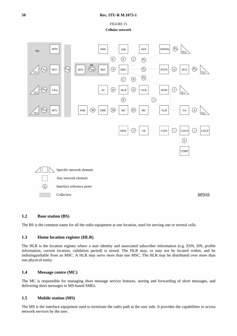
50 Rec. ITU-R M.1073-1
1073-15
H
F LE
RxTE2
TE2DCE
MSC
C B
SME MC MCSME
MNE OS
TE1
TE2TA
CDIS CDGP CDCP
CDRP
MT0
N
A
Pi
Ai
Di
IWF
MT1
TAm
MT2
O
W Rv
S
G
R
AbisBTS BSC
BS
H D
M M M
I J
K
UmSm
Rm
mR
MS
TE1
TE2
TE2
FIGURE 15
Cellular network
Specific network element
Any network element
Interface reference point
Collective
AC
PSPDN
PSTN
ISDN
MSC
HLR VLR
VLR
EIR
FIGURE 15 [1073-15]= 15 CM
1.2 Base station (BS)
The BS is the common name for all the radio equipment at one location, used for serving one or several cells.
1.3 Home location register (HLR)
The HLR is the location register where a user identity and associated subscriber information (e.g. ESN, DN, profileinformation, current location, validation period) is stored. The HLR may, or may not be located within, and beindistinguishable from an MSC. A HLR may serve more than one MSC. The HLR may be distributed over more thanone physical entity.
1.4 Message centre (MC)
The MC is responsible for managing short message service features, storing and forwarding of short messages, anddelivering short messages to MS-based SMEs.
1.5 Mobile station (MS)
The MS is the interface equipment used to terminate the radio path at the user side. It provides the capabilities to accessnetwork services by the user.
Rec. ITU-R M.1073-1 51
1.6 Mobile services switching centre (MSC)
The MSC is an automatic system which constitutes the interface for user traffic between the cellular network and otherpublic switched networks, or other MSCs in the same or other cellular networks. As used in this Appendix, the term“traffic” refers to information conveyed to, or from the user, as opposed to information involving the management of thenetwork.
MSCs can take on different roles as:
Anchor MSC: the first MSC of radio contact in a call.
Border MSC: an MSC controlling cells adjacent to the location of a mobile station.
Candidate MSC: an MSC which could possibly accept a call for handoff.
Originating MSC: the MSC detecting an incoming call toward a mobile station.
Remote MSC: the MSC at the other end of an intersystem handoff trunk.
Serving MSC: the MSC currently providing service to a call.
Tandem MSC: an MSC providing only trunk connections for a handed off call.
Target MSC: the MSC selected for a handoff.
Visited MSC: an MSC providing service to the mobile station.
1.7 Short message entity (SME)
The SME is an entity which is responsible for the composition and disposition of short messages delivered through themessage centre.
1.8 Visitor location register (VLR)
The VLR is the location register other than the HLR used by an MSC to retrieve information for handling of calls to orfrom a visiting subscriber. The VLR may, or may not be located within, and be indistinguishable from an MSC. TheVLR may serve more than one MSC.
2 Intersystem services
Services requiring intersystem operations include:
– intersystem handoff (Handover),
– automatic roaming,
– authentication and privacy,
– voice services,
– intelligent networking,
– short message services,
– border system solutions,
– operations and maintenance.
2.1 Intersystem handoff (handover)
Intersystem handoff (handover) allows a call in progress to be automatically transferred without interruption from aradio channel under the control of one MSC to a different radio channel under the control of another MSC. IS-41supports intersystem handoff across multiple air interface technologies (e.g., analogue and digital technologies such asAMPS, TDMA, CDMA, narrow-band AMPS).
52 Rec. ITU-R M.1073-1
A handoff process is triggered when the system serving a MS determines, through a signal measurement process(e.g., intersystem signal measurements or a mobile assisted handoff), that the MS should handoff to a target cell. Thehandoff occurs when the MS is instructed to re-tune to a specified channel on the target cell.
The IS-41 handoff functionality is provided through a series of basic operations which include:
– FacilitiesDirective – Used to request the target MSC (recipient) to initiate a handoff forward task.
– FacilitiesRelease – Used to request all allocated resources for a call segment to be released.
– FlashRequest – Used to inform the anchor MSC that a flash was received from the specified MS.
– HandoffBack – Used to request the target MSC (recipient) to initiate a handoff backward task.
– HandoffMeasurementRequest – Used by the serving MSC to request a neighbouring MSC to perform a signalquality measurement on a specified traffic channel.
– HandoffToThird – Used by the serving MSC to initiate a handoff with path minimization.
– InformationForward – Used after handoff to transfer information concerning the served MS toward theserving MSC.
– InterSystemAnswer – Used after handoff to inform a border MSC that the called party has answered.
– MobileOnChannel – Used by the target MSC to confirm the arrival of the MS on the new traffic channel.
2.2 Automatic roaming
Automatic roaming automatically provides cellular telephone services to mobile stations which are operating outsidetheir home service area, but within the service area of another MSC. Automatic roaming services include:
– timely identification of the current serving MSC. This is performed through a registration process that is triggeredwhen the mobile station accesses a system (e.g., autonomous registration, call origination attempt, response to a calltermination attempt);
– automatic service authorization of a roaming MS (e.g., credit validation). This can be performed during theregistration process or on request of a visited system. If the validation status changes, the mobile station’s homesystem can remove or change a previously granted authorization;
– delivery of the service profile for the roaming mobile station. This can be performed during the registration process(i.e., transfer of subscriber’s profile of services from the mobile station’s home system to the visited system), uponrequest of the visited system, or under the direction of the mobile station’s home system when a feature status haschanged;
– access and control of features and services by the roaming mobile station. This allows a subscriber to alter the statusof subscribed features and services.
Automatic roaming functionality is provided through a series of basic operations which include:
– BulkDeregistration – Used by a VLR to inform a HLR that all MS data associated with the HLR has beenremoved.
– FeatureRequest – Used to request feature related treatment for digits received from the specified MS.
– MSInactive – Used to indicate the specified MS is inactive.
– QualificationDirective – Used to update authorization, profile information, or both for a specified MS.
– QualificationRequest – Used to request validation of an MS, profile information or both.
Rec. ITU-R M.1073-1 53
– RegistrationCancellation – Used to report to a network element that the specified MS is no longer is in the servingarea.
– RegistrationNotification – Used to report the location of the specified MS, to validate the MS and to obtain theprofile of the MS.
– ServiceProfileDirective – Used to inform the serving system of a change in the MS’s service profile.
– ServiceProfileRequest – Used to retrieve the specified MS’s service profile.
– UnreliableRoamerDataDirective – Used by the HLR to request the VLR to remove the records of the mobilestations associated with the HLR.
2.3 Authentication and privacy
IS-41 provides security features to verify a mobile station’s identity and provide for privacy of user communications.
Verification of the identity of a mobile station is performed through authentication procedures. Authentication occurs onevery service request (e.g., registration, call origination attempt, response to a call termination attempt) made by themobile station.
The basic concept of authentication relies on performing an authentication challenge. The mobile station (MS) is“challenged” with a random variable. The random variable challenge and other mobile station parameters are inputs intoa Cellular Authentication and Voice Encryption (CAVE) algorithm to generate an authentication response. Theauthentication response received from the MS is compared to the response expected by the authentication centre (AUC).
The MS may also authenticate network connectivity to the AUC with a base station challenge. This process is similar toMS authentication, except that the MS generates the random variable and compares the authentication responses.
The integral component of authentication is the “authentication” key (A-key). The A-key is secret and is known only bythe MS and AUC. The A-key is used to derive shared secret data which may be shared between systems and systemoperators without compromising the A-key. When shared secret data is used with a visited system, network bandwidthmay be saved by allowing the VLR to perform some of the AUC’s authentication responsibilities.
Encryption keys for voice privacy and signalling message encryption are generated during the authentication procedures.The encryption keys are used to ensure privacy over digital traffic channels and signalling channels.
Authentication and privacy are supported by the following operations:
– AuthenticationDirective – Used to request modifications of the specified MS’s authentication parameters.
– AuthenticationDirectiveForward – Used from the Anchor MSC to request the serving MSC to initiate a uniquechallenge for the specified MS.
– AuthenticationFailureReport – Used to report the failure of an autonomous authentication operation for thespecified MS.
– AuthenticationRequest – Used to request authentication of the specified MS.
– AuthenticationStatusReport – Used to report the results of requested authentication operations for thespecified MS.
– BaseStationChallenge – Used to report the results of a base station challenge authentication operation for thespecified MS.
– CountRequest – Used to obtain the call history count parameter value for the specified MS.
54 Rec. ITU-R M.1073-1
2.4 Voice services
IS-41 supports the protocol and procedures that enables a mobile station to access voice services and features whileroaming. IS-41 transports the information necessary for the serving system to supply the service to the mobile station.
Automatic call delivery is performed through a series of operations that notify the visited system of an incoming call andassociate the call with a temporary local directory number assignment by the visited system. The temporary localdirectory number is used to route the incoming call to the called mobile station.
The following supplementary services are supported by IS-41 and described in TIA/EIA IS-53-A:
– call forwarding (CF) services
– CF unconditional
– CF busy
– CF no answer
– CF default
– call termination services
– call delivery
– call waiting
– calling number identification presentation
– calling number identification restriction
– do not disturb
– flexible alerting
– message waiting notification
– mobile access hunting
– call origination services
– preferred language
– priority access and channel assignment
– remote feature control
– voice mail retrieval
– multiple party services
– call transfer
– conference calling
– three-way calling
– call restriction services
– password call acceptance
– selective call acceptance
– subscriber PIN access
– subscriber PIN intercept
– privacy services
– voice privacy
– signalling message encryption
The IS-41 operations to support voice services include:
– CallDataRequest – Used to request an HLR to return MS data associated with the specified directory number.
– InformationDirective – Used by the HLR to provide a notification to the specified MS.
Rec. ITU-R M.1073-1 55
– LocationRequest – Used by an originating MSC to obtain routing instructions from the HLR for a call to adirectory number.
– OriginationRequest – Used to request call origination treatment for digits received from the specified MS.
– RedirectionDirective – Used during feature processing to direct the MSC to forward the specified call.
– RedirectionRequest – Used by the serving MSC to request the originating MSC to redirect the specified call.
– RemoteUserInteractionDirective – Used by the HLR to direct the operation of a network element that providesuser interactions.
– RoutingRequest – Used by the HLR to request the assignment and association of a Temporary local directorynumber (TLDN) with a termination to a MS, dialogue, or voicemail port in a serving MSC.
– TransferToNumberRequest – Used during feature processing to obtain from the HLR the specified MS’s forwardto number.
2.5 Short message services
A point-to-point bearer service is supported which can be used to transport any number of short message teleservices.Short message service is supported by the following IS-41 operations:
– SMSDeliveryBackward – Used after handoff to deliver a MS originated short message to the anchor MSC.
– SMSDeliveryForward – Used after handoff to deliver a MS terminating short message to the serving MSC.
– SMSDeliveryPointToPoint – Used to convey a short message.
– SMSNotification – Used to report a change in the specified MS’s ability to receive a short message.
– SMSRequest – Used to request the specified MS’s current short message routing address and to requestnotification of the MS’s availability to receive short messages (if it is not currently available for short messagedelivery).
2.6 Border system solutions
IS-41 provides solutions to “border cell” problems that are due to RF anomalies at intersystem borders. These anomaliescan occur in densely populated urban areas and under other circumstances.
Intersystem paging from the serving MSC to the “border” MSC is performed during call delivery to locate a mobilestation in a border area. Call routing will be performed to the system in which the subscriber is found. Intersystempaging is also performed during call delivery to request a border MSC to “listen” for an unsolicited page responselocation failure.
Received signal strength information and timing considerations are used to detect multiple systems accepting a singleregistration from a mobile station, and to select the “best ” system to serve the mobile station.
Intersystem operations are provided to request random variable challenge information from a border system when amobile station has received the challenge from the border system.
Solutions to border cell problems are provided through a series of basic operations that include:
– InterSystemPage – Used by the serving MSC to request a border MSC to page a specified MS or to listen for apage response from a specified MS.
– InterSystemSetup – Used by the serving MSC to request a border MSC to perform call delivery traffic channelconnection actions.
56 Rec. ITU-R M.1073-1
– RandomVariableRequest – Used by the serving MSC to request the value of an authentication random variablefrom a border MSC.
– UnsolicitedResponse – Used by an MSC to inform a border MSC that a page response has been received from thespecified MS which the MSC had not paged.
2.7 Operations and maintenance
The IS-41 protocol and procedures also support operations for performing trunk maintenance and diagnostics fordedicated handoff trunk circuits between two systems.
The operations and maintenance functionality is provided through a series of operations which include:
– Blocking – Used by an MSC to inform a remote MSC that the specified circuit has been removed from service.
– ResetCircuit – Used by an MSC to restore information about a specified circuit’s condition or to place a circuitinto service.
– TrunkTest – Used by an MSC to request the specified trunk circuit be place into the testing mode by theremote MSC.
– TrunkTestDisconnect – Used by an MSC to request the specified trunk circuit test be disconnected by theremote MSC.
– Unblocking – Used by an MSC to inform the remote MSC that the specified trunk circuit has been placedinto service.
BIBLIOGRAPHY
ANSI/EIA/TIA Standard 553. Mobile Station – Land Station Compatibility Specification. American National StandardsInstitute/Electronic Industries Association/Telecommunications Industry Association. September, 1989.
EIA/TIA IS-52-A. Uniform Dialling Procedures and Call Processing Treatment for Use in Cellular Radio Telecommunications.Electronic Industries Association/Telecommunications Industry Association.
EIA/TIA IS-54-B. Cellular System Dual-Mode Mobile Station – Base Station Compatibility Standard. April, 1992.
EIA/TIA IS-88. Mobile Station – Land Station Compatibility Standard for Dual-Mode Narrow-Band Analogue Cellular Technology.February, 1993.
TIA/EIA IS-91. Mobile Station – Land Station Compatibility Standard. Telecommunications Industry Association/ElectronicIndustries Association. 1994.
TIA/EIA IS-95. Mobile Station – Base Station Compatibility Standard for Dual-Mode Wideband Spread Spectrum Cellular System.July, 1993.
TIA/EIA IS-124. Cellular Radio Telecommunications Intersystem Non-Signalling Data Communications (DMH). 1993.
TIA/EIA IS-136. Cellular System Mobile Station – Land Station Compatibility Standard. 1994.
APPENDIX 2
Call detail recording
1 Overview
Telecommunications Industry Association/Electronic Industries Association (TIA/EIA) IS-124 Cellular IntersystemNon-Signalling Data Communications is an interim standard describing a means for exchanging wireless subscriberusage information in a near real time basis. The information pertains to usage of cellular customers who originate orreceive calls while roaming as well as other events and activities of those customers any visited system. IS-124 definesthe services for transferring call detail information between functional entites, allowing for automatic mechanisms forrecording and delivering information for charging and billing purposes, etc.
Rec. ITU-R M.1073-1 57
2 Objectives
The objectives of this interim standard are to define the services for transferring call detail information between entitiesin a near real time method. Included are automatic mechanisms for recording and delivering the following information:
– All call attempts, toll accesses, and feature activation attempts and any visited system.
– All call delivery attempts including call delivery through tandeming systems.
– All air channel usage.
– All intersystem tandem trunk usage.
– All feature usage and activations.
Additional mechanisms are provided for the following:
– Requesting rating information.
– Requesting call detail information.
– Intersystem accounting for accumulated usage.
– Requesting an intersystem accounting.
The delivery delay between the conclusion of a reportable activity and the transmission of the last bit of call detailinformation to the consumer of that information, should be less than 60 s 95% of the time. The absolute worst deliverydelay should be less than 15 min.
Certified transfers should duplicate no more than one record in 10 000 000. Certified delivery should lose no more thanone record in 10 000 000 records.
3 Call detail records
There are five basic types of call detail records:
– An audit record that summarizes a call.
– A leg record that details trunk and feature usage within a call.
– A segment record that details individual facility usage.
– An activity record that details subscriber usage activities involving radio contact.
– An event record that details events which may affect subscribers.
An audit record is generated for each call origination and termination attempt.
A leg record is generated for each call origination, termination or feature activation attempt by a wireless subscriber.One leg record is generated for each extension or redirection of a call toward its destination. A single call may havemore than one leg record.
The segment record contains information concerning individual facility usage by a subscriber. The records are used foraccounting details of radio resource usage, for inter-carrier facility usage settlement and for other analysis purposes.
The activity report record is used to describe subscriber activity that does not have an associated duration, but involvesradio contact. This includes activities such as registration, handoff, deregistration or a change in call mode.
The event report record is used to describe events which do not have radio contact. This includes events such as featureactivation, authorizations, authentications, registration cancellation, declared subscriber inactivity or subscriber problemdetection.
58 Rec. ITU-R M.1073-1
4 Call record identifiers
The objectives of the identifiers in the call records are used to:
– Establish the relationship between the separate records pertaining to a single call.
– Establish the relationship between the separate systems involved in a single call.
Each leg record contains the billing identification number (BIN) which is used to tie the legs records of a call together.
All segment records share a common audit record and a common billing identification number regardless of how manysystems are involved in a handoff. IS-41 messages carry the BIN between systems.
Sequence and serial numbers are employed to detect missing and duplicate message cases and to uniquely identify eachcomponent.
Serial numbers are used in the IS-124 as follows:
– Calls Billing identification number (BIN)
– Reports Report identification number (RIN)
– Segment Concatenation of the BIN and segment sequence number
– Leg Concatenation of the BIN and leg sequence number.
A sequence number is a sequential identifier used to ensure that all concerned components are properly collected. Eachcomponent is assigned a sequence number.
Call are assigned a billing identification number (BIN). The number is unique within a system over a sufficiently longperiod of time for the particular application.
APPENDIX 3
General description of an open mobile service switching centreto base station controller interface
(MSC-to-BSC interface)
1 Introduction
This Appendix describes the IS-634 standard published by the Telecommunications Industry Association (TIA) for useby many of the North American wireless networks. IS-634 is a complete specification for open interface between thebase station controller (BSC) and mobile service switching centre (MSC) equipment in a wireless network. TheMSC-to-BSC interface is defined as the interface that provides telecommunications services access between a basestation controller (BSC) and a mobile service switching centre (MSC). It is also known as the A-interface.
The explicit requirement for the development of IS-634 was the need to support many of the air interfaces operating inNorth America. However, the design of IS-634 was modular, and greatly influenced by the A-interface standardsoperating elsewhere like the GSM system in Europe and the PDC system in Japan.
The scope of the IS-634 standard includes the following topics:
– the descriptions of the functional capabilities that provide wireless telecommunications services across theMSC-to-BSC interface;
– the descriptions of the division of responsibility of the functions provided between the BSC and the MSC withoutprescribing specific implementations;
Rec. ITU-R M.1073-1 59
– the descriptions of the MSC-to-BSC interface standards that support the various air interfaces operating in NorthAmerica. Specifically, the following air interface standards:
– analogue (TIA/EIA-553),
– narrow-band analogue (EIA/TIA IS-91),
– digital CDMA dual mode (EIA/TIA IS-95).
2 Organization
IS-634 describes procedures necessary to provide to cellular radio telephone subscribers certain services requiringinteraction between the mobile service switching centre (MSC) and the base station controller (BSC). It describes andprovides specification of the following topics and functions:
– functional overview of the A-interface,
– call processing and supplementary services,
– radio resource management,
– mobility management, authentication, and privacy,
– layer 1 and 2 and terrestrial facility management,
– messages, parameters, and timer definitions,
– Annexes.
IS-634 addresses the ongoing and developing concerns of the North American cellular radio telecommunicationsindustry – subscribers, service providers, and manufacturers alike – with regard to useful and effective services requiringstandardized procedures.
3 Interface structure
The MSC-to-BSC interface defined in IS-634 includes two major components:
– First is the base station controller application part (BSAP). This encompasses the set of procedures and signallingmessages needed between the MSC and BSC to perform various wireless applications like call origination, calltermination, registration, handoff, and a limited set of trunk maintenance procedures.
– Second is the transport facility which consists of the physical transmission facility that connect the MSC withthe BSC, and the SS No. 7/C7 signalling protocol that guarantee the delivery of the BSAP messages from one endto another.
The various components that are used in this interface are indicated and defined in Fig. 16. Further definition of thesefunctions and protocols are provided in § 3.1 through 3.2.4.
3.1 Transport facility
The MSC-to-BSC interface referred to in this Appendix is designed to support a wide range of possible architectures onboth sides of the interface. Characteristics like the physical location of the transcoder inside the BSC (either integratedinto the transceivers or very near to the MSC), or the use of traffic or signalling concentration at either side are left to theoperator’s choice.
The physical interface is based on the use of one or more T1 (1.544 Mbit/s) digital transmission system interfaces. Each1.544 Mbit/s interface provides 24*56 kbit/s (or 24*64 kbit/s) channels which can be used for traffic or signalling as theoperator requires. Common physical interface standards are found in ANSI T1.101 and related references.
The underlying transport mechanism defined to carry signalling information between the BSC and the MSC is themessage transfer part (MTP), and the signalling connection control part (SCCP) of Signalling System No. 7. The MTPand SCCP are used to transport the messages of the application layer BSAP.
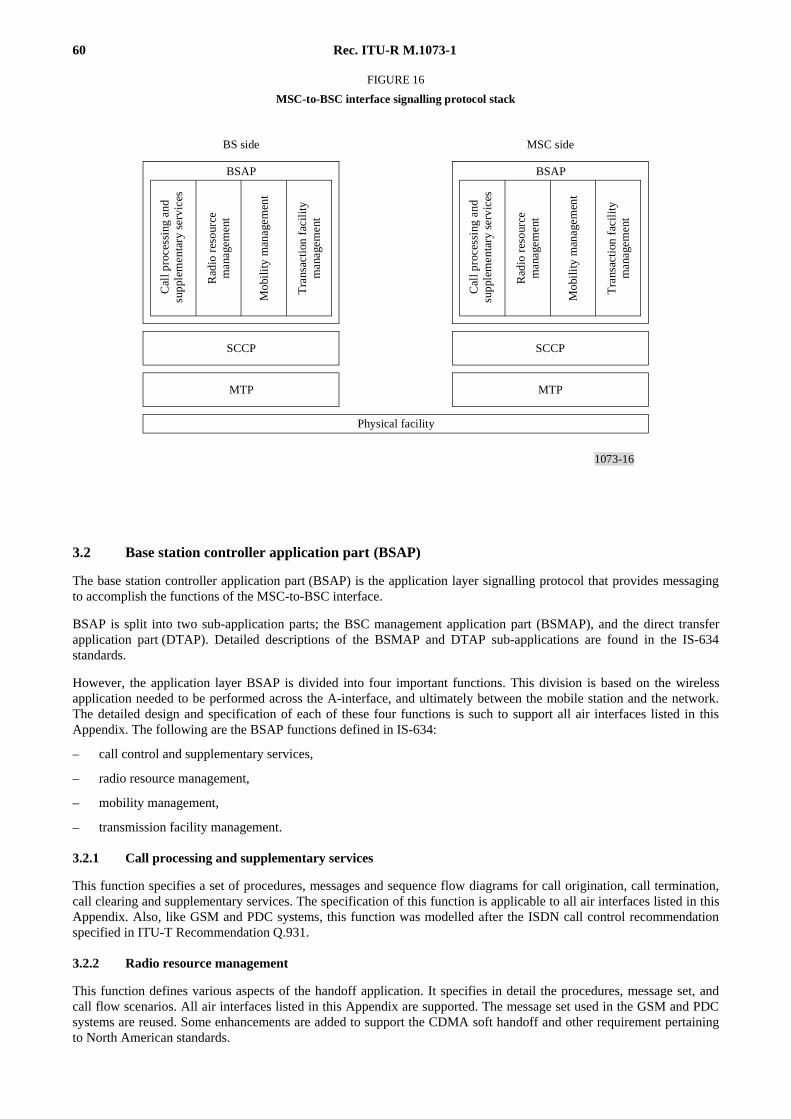
60 Rec. ITU-R M.1073-1
1073-16
BSAP
SCCP
MTP
BSAP
SCCP
MTP
FIGURE 16
MSC-to-BSC interface signalling protocol stack
Cal
l pro
cess
ing
and
supp
lem
enta
ry s
ervi
ces
Rad
io r
esou
rce
man
agem
ent
Mob
ilit
y m
anag
emen
t
Tra
nsac
tion
fac
ility
man
agem
ent
BS side
Cal
l pro
cess
ing
and
supp
lem
enta
ry s
ervi
ces
Rad
io r
esou
rce
man
agem
ent
Mob
ilit
y m
anag
emen
t
Tra
nsac
tion
fac
ility
man
agem
ent
MSC side
Physical facility
FIGURE 16 [1073-16]= 9.5 CM
3.2 Base station controller application part (BSAP)
The base station controller application part (BSAP) is the application layer signalling protocol that provides messagingto accomplish the functions of the MSC-to-BSC interface.
BSAP is split into two sub-application parts; the BSC management application part (BSMAP), and the direct transferapplication part (DTAP). Detailed descriptions of the BSMAP and DTAP sub-applications are found in the IS-634standards.
However, the application layer BSAP is divided into four important functions. This division is based on the wirelessapplication needed to be performed across the A-interface, and ultimately between the mobile station and the network.The detailed design and specification of each of these four functions is such to support all air interfaces listed in thisAppendix. The following are the BSAP functions defined in IS-634:
– call control and supplementary services,
– radio resource management,
– mobility management,
– transmission facility management.
3.2.1 Call processing and supplementary services
This function specifies a set of procedures, messages and sequence flow diagrams for call origination, call termination,call clearing and supplementary services. The specification of this function is applicable to all air interfaces listed in thisAppendix. Also, like GSM and PDC systems, this function was modelled after the ISDN call control recommendationspecified in ITU-T Recommendation Q.931.
3.2.2 Radio resource management
This function defines various aspects of the handoff application. It specifies in detail the procedures, message set, andcall flow scenarios. All air interfaces listed in this Appendix are supported. The message set used in the GSM and PDCsystems are reused. Some enhancements are added to support the CDMA soft handoff and other requirement pertainingto North American standards.
Rec. ITU-R M.1073-1 61
3.2.3 Mobility management
This function specifies procedures, message definitions, and call flow diagrams for the registration, authentication andprivacy applications. Although some reuse of the GSM and PDC is employed in specifying this section, a substantialenhancement is added to support the North American air interface requirement, specifically in the area of authenticationand privacy.
3.2.4 Transmission facility management
Like the GSM and PDC system, this function provides a limited set of trunk maintenance procedures for the terrestrialA-interface. Like in the GSM and PDC systems, the procedures, message definitions and message flow diagramsspecified in IS-634 support trunk blockage, trunk and system reset, transcoder control, and generic overload controlapplications.
GENERAL REFERENCES
ANSI J-STD-007. Air Interface Specification for 1.8 to 2.0 GHz Frequency Hopping Time Division Multiple Access (TDMA) forPersonal Communications Services, United States of America. American National Standards Institute.
ANSI J-STD-008. Personal Station-Base Station Compatibility Requirements for 1.8 to 2.0 GHz Code Division Multiple Access(CDMA) Personal Communications Systems.
ANSI J-STD-009. PCS IS-136 Based Mobile Station Minimum Performance 1 900 MHz Standard.
ANSI J-STD-010. PCS IS-136 Based Base Station Minimum Performance 1 900 MHz Standard.
ANSI J-STD-011 PCS IS-136 Based Air Interface Compatibility 1 900 MHz Standard.
ANSI J-STD-014. Personal Access Communication System Air Interface Standard.
ANSI J-STD-015 (Trial Use) and EIA/TIA IS-665. W-CDMA (Wideband Code Division Multiple Access) Air InterfaceCompatibility Standard for 1.85 to 1.99 GHz PCS Applications. American National Standards Institute and ElectronicIndustries Association/Telecommunications Industry Association.
ANSI J-STD-017 (Trial Use) and EIA/TIA IS-661. A Composite CDMA/TDMA Air Interface Compatibility Standard for PersonalCommunications in 1.85-1.99 GHz for Licensed Applications.
ANSI J-STD-019. Recommended Minimum Performance Requirements for Base Stations Supporting 1.8 to 2.0 GHz Code DivisionMultiple Access (CDMA) Personal Stations.
EIA/TIA IS-41-C. Cellular Radiotelecommunications Intersystem Operations. Electronic Industries Association/TelecommunicationsIndustry Association. 1995.
EIA/TIA IS-53-A. Cellular Features Description. 1995.
EIA/TIA IS-54 Rev. B. Cellular System Dual Mode Mobile Station – Base Station Compatibility Standard.
EIA/TIA-553. Cellular System: Mobile Station – Land Station Compatibility Specification. September, 1989.
ETSI.GSM specifications. European Telecommunications Standards Institute, Sophia Antipolis, F-06291 Valbonne Cedex, France.
RCR [1995] Personal Digital Cellular Telecommunication System. Research and Development Centre for Radio Systems, Japan.RCR Standard STD-27D/1995.6.27.
TIA/EIA IS-41-C. Cellular Radiotelecommunications Intersystem Operations. Telecommunications Industry Association/ElectronicIndustries Association.
TIA/EIA IS-91. Mobile Station-Base Station Compatibility Standard for 800 MHz Analogue Cellular.
TIA/EIA IS-95-A. Mobile Station-Base Station Compatibility Standard for Dual-Mode Wideband Spread Spectrum Cellular System.
TIA/EIA IS-99. Data Services Option Standard for Wideband Spread Spectrum Digital Cellular System.

62 Rec. ITU-R M.1073-1
TIA/EIA IS-136.1. 800 MHz TDMA Cellular – Radio Interface – Mobile Station – Base Station Compatibility – Digital ControlChannel.
TIA/EIA IS-136.2. 800 MHz TDMA Cellular – Radio Interface – Mobile Station – Base Station Compatibility – Traffic Channelsand FSK Control Channel.
TIA/EIA IS-634. MSC-to-BSC Interface for Public 800 MHz.
TIA/EIA IS-637. Short Message Services for Wideband Spread Spectrum Digital Cellular Systems.
TIA/EIA IS-657. Packet Data Services for Wideband Spread Spectrum Digital Cellular Systems.