m1018 manual 4.09 - northern tool + equipment · tailstock controls ... b% feed rate lever c% power...
TRANSCRIPT


Woodstock Technical Support ............................................................................ 3About Your New Combo Lathe/Mill ...................................................................... 3Specifications ............................................................................................... 4Controls and Features ..................................................................................... 5
Standard Safety Instructions ............................................................................. 6Additional Safety Instructions for Lathe/Mill Combos ............................................... 8
110V Operation ............................................................................................. 9Extension Cords ............................................................................................ 9Electrical Specifications .................................................................................. 9
Unpacking ................................................................................................. 10Inventory .................................................................................................. 10Machine Placement ...................................................................................... 11Cleaning Machine and Components ................................................................... 11Handle and Hand Crank ................................................................................. 12Lathe Test Run ............................................................................................ 13Mill Test Run .............................................................................................. 14
General .................................................................................................... 15Switching to Lathe ....................................................................................... 15Determining Correct Spindle Speed—Lathe .......................................................... 16Spindle Speeds ............................................................................................ 17Lathe Spindle Break-In .................................................................................. 17Power Feed Controls ..................................................................................... 18Manual Carriage Controls ............................................................................... 19Tailstock Controls ........................................................................................ 203-Jaw Scroll Chuck ....................................................................................... 214-Jaw Chuck Plate ....................................................................................... 24Faceplate .................................................................................................. 25Dead Center ............................................................................................... 26Turret Tool Post ........................................................................................... 27Drill Chuck ................................................................................................ 28Gear Charts ............................................................................................... 29Changing Gears ........................................................................................... 30Aligning Tailstock to Spindle Center .................................................................. 31
General .................................................................................................... 33Switching to Mill.......................................................................................... 33Determining Correct Spindle Speed—Mill ............................................................. 34Spindle Speeds ............................................................................................ 35Mill Spindle Break-In ..................................................................................... 36Quill Lock .................................................................................................. 36Downfeeds ................................................................................................. 36Moving Mill Head ......................................................................................... 36Drill Chuck ................................................................................................ 37

General .................................................................................................... 38Maintenance Schedule ................................................................................... 38Lubrication ................................................................................................ 38
General .................................................................................................... 40Adjusting Gibs ............................................................................................ 40Wiring Diagram ........................................................................................... 42Troubleshooting........................................................................................... 43
Warranty Registration ................................................................................... 59

-3-
We stand behind our machines! In the event that questions arise about your machine, parts are miss-ing, or a defect is found, please contact Woodstock International Technical Support at (360) 734-3482 or send e-mail to: . Our knowledgeable staff will help you troubleshoot prob-lems and send out parts for warranty claims.
If you need the latest edition of this manual, you can download it from . If you still have questions after reading the latest manual, or if you have comments please contact us at:
Your new ® Combo lathe/mill has been specially designed to provide many years of trouble-free service. Close attention to detail, ruggedly built parts and a rigid quality control program assure safe and reliable operation.
Hobby or entry-level machinists will find this versatile machine great for turning, cutting threads, drilling and milling small projects. Packed with extra add-ons like a 4-way turret tool post, 9 1⁄2" faceplate, 4" 3-jaw chuck, and a built-in rotating vise. Features a 16 1⁄2" swing over bed, 11 1⁄2" swing over saddle, 19 3⁄16" distance between centers, 3⁄4" spindle bore, and MT#3 tapers.
Woodstock International, Inc. is committed to customer satisfaction in providing this manual. It is our intent to make sure all the information necessary for safety, ease of assembly, practical use and durabil-ity of this product be included.

-4-
Motor Type ....................................................................TEFC Capacitor Start InductionHorsepower ................................................................................................. 3⁄4 HPSwitch ..................................................................Push Button, Reversing, Single PhaseVoltage ........................................................................................................ 110VAmps ............................................................................................................. 9 AMotor RPM .............................................................................................. 1725 RPMBearings .....................................................................Shielded And Lubricated For LifeDesign Type ......................................................................................... Bench ModelOverall Length ................................................................................................. 42"Overall Width................................................................................................... 23"Overall Height ................................................................................................. 35"Bed Width ..................................................................................................... 51⁄2"Spindle Bore .................................................................................................... 3⁄4"Lathe, Drill Press and Tailstock Tapers ...................................................... #3 Morse TaperWeight (Net) .............................................................................................. 440 lbs.Weight (Shipping) ........................................................................................ 500 lbs.Crate Size ................................................................................. 41" L x 24" W x 39" HFootprint ................................................................................................. 42" x 23"Swing Over Bed ............................................................................................. 16 1⁄2"Swing Over Saddle .......................................................................................... 11 1⁄2"Distance Between Centers ................................................................................19 1⁄4"Spindle ................................................................................... Intrinsic 4" Back PlateCompound Travel ................................................................................................3''Cross Slide Travel ............................................................................................ 4 1⁄2"Tailstock quill Travel ........................................................................................ 1 1⁄2"Spindle Speeds .................................................... 185, 330, 405, 535, 680, 955, 1455 RPMFeed Rate Range ............................................................................ 8 @ 0.002"–0.0069"Thread Range Inch........................................ 8-120 TPI in 27 Steps (Gear changes required)Thread Range Metric ....................................................................... 18 @ 0.2 - 3.0 mmLead Screw ............................................................................................ 7⁄8"-10 TPICross Slide Screw ..................................................................................... 1⁄2"-10 TPISwing ............................................................................................................ 12''Spindle to Bed............................................................................................... 15 3⁄4"Spindle Travel ................................................................................................ 3 1⁄2"Spindle to Work Table ......................................................................................... 10"Spindle to Center Line ...................................................................................... 9 3⁄4"Head Stock Height Adjustment ................................................................................3"Range of Speeds ................................................... 117, 150, 220, 276, 290, 345, 360, 440, 450, 575, ........................................................................................................ 640, 836, 1000, 1300 RPMNumber of Speeds .............................................................................................. 14Maximum Drilling Capacity ................................................................................... 7⁄8"Lathe Tooling Size ............................................................................................. 1⁄2"Drill Chuck Capacity..................................................................................... 1⁄16"–1⁄2"

-5-
Fine Downfeed Coarse Downfeed Engagement Knob Mill Head Elevator Power Indicator Light OFF Button ON Button FWD/REV Switch
Main Power SwitchMain Pulley Access Door
Feed Rate Lever Power Feed Lever
Half Nut Lever Cross Slide Handwheel Carriage Lock
Vise/Compound SlideCompound Slide Hand CrankTailstock Lock
Carriage Longitudinal Hand CrankTailstock Offset ScrewTailstock HandwheelTailstock Lock
Dead Center Turret Tool Post
Oil Sight Glass3-Jaw ChuckDrill Chuck
Quill LockMill Pulley Cover
Drawbar Cover Cap
AB
C
D
E
F
G
H
I
J
K
L
MN O P
Q RS
T
VW
X
Z
AA
U
Y
AB
AC
AD
Model M1018 Features and Controls.

-6-
Learn the applications, limitations and potential hazards of this machine. Keep the manual in a safe and convenient place for future reference.
Clutter and inadequate lighting invite potential hazards.
If a machine is equipped with a three-prong plug, it must be plugged into a three-hole grounded electrical receptacle or grounded extension cord. If using a chuck plate to aid in accommodating a two-hole receptacle, ground using a screw to a known ground.
Use safety glasses with side shields or safety goggles that meet the appropriate standards of the American National Standards Institute (ANSI).
DO NOT operate this machine in wet or open flame environments. Airborne dust particles could cause an explosion and severe fire hazard.
and in working condition.
before connecting power to machine.
free of clutter, grease, etc.
Visitors must be kept at a safe distance while operating unit.
with padlocks, master switches or by removing starter keys.
Indicates an imminently hazardous situation which, if not avoided, WILL result in death or serious injury.
Indicates a potentially hazardous situation which, if not avoided, COULD result in death or serious injury.
Indicates a potentially hazardous situation which, if not avoided, MAY result in minor or moderate injury.
This symbol is used to alert the user to useful information about proper operation of the equipment, and/or a situation that may cause damage to the machinery.

-7-
The machine will do a safer and better job at the rate for which it was designed.
DO NOT force machine or attachment to do a job for which it was not designed.
DO NOT wear loose clothing, neck ties, gloves, jewelry, and secure long hair away from moving parts.
Before turning the machine on, make it a habit to check that all adjusting keys and wrenches have been removed.
But if you must use one, examine the extension cord to ensure it is in good condition. Immediately replace a damaged extension cord. Always use an extension cord that uses a ground pin and connected ground wire. Use an extension cord that meets the amp rating on the motor nameplate. If the motor is dual voltage, be sure to use the amp rating for the voltage you will be using. If you use an extension cord with an undersized gauge or one that is too long, excessive heat will be generated within the circuit, increasing the chance of a fire or damage to the circuit.
at all times.
.
Wait until it comes to a complete stop before leaving the area.
Follow lubrication and accessory attachment instructions in the manual.
Operating machines near pilot lights or open flames creates a high risk if dust is dispersed in the area. Dust particles and an ignition source may cause an explo-sion. DO NOT operate the machine in high-risk areas, including but not limited to, those mentioned above.
difficulties performing the intended operation, stop using the machine! Then contact our technical support or ask a qualified expert how the operation should be performed.
Develop good habits in your shop and safety will become second-nature to you.

-8-
DO NOT operate until unit is assembled and installed, according to instructions, on a flat, stable surface.
Turn machine and wait until machine has come to a complete stop to clear away chips. Chips are sharp. Use a brush to clear them.
. Place a board across the bedway when removing/installing the chuck to prevent finger pinches between the chuck and the bedway, and to avoid damaging the bedway.
Before starting the lathe/mill, be certain the workpiece and cutter are properly secured and that there is adequate clearance for full motion.
Always use the proper cutting tools for the material you are machining; make certain they are sharp and that they are held firmly in the tool post, collet, or chuck.
. Make sure the tool post provides proper support for the turning tool you will be using. Test tool post clearance by rotating workpiece by hand before turning lathe .
Always remove your chuck key, drawbar wrench, and any service tools immediately after use.
DO NOT exceed the recommended spindle speed for the type of work, material, and tool bit. Allow the lathe/mill to reach full speed before cutting.
. Never reverse motor direction while the lathe/mill is in motion.
Allow the lathe/mill to come to a complete stop before leaving it unattended. DO NOT stop lathe using your hand against the workpiece or chuck.
. Never operate the lathe/mill with damaged or worn parts. Inspect cutters for sharpness, chips or cracks before each use. Replace damaged cutters immediately.
. Make sure lathe/mill is turned OFF, unplugged, and the machine has come to a com-plete stop before servicing. Perform routine inspections and service promptly.
Coolants used for machining may contain hazardous chemicals. Read and understand all user information on the coolant container and take any necessary precautions.
-9-
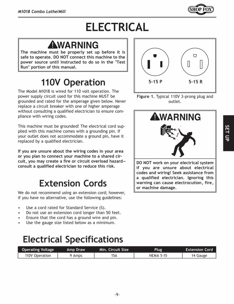
Typical 110V 3-prong plug and outlet.
The Model M1018 is wired for 110 volt operation. The power supply circuit used for this machine MUST be grounded and rated for the amperage given below. Never replace a circuit breaker with one of higher amperage without consulting a qualified electrician to ensure com-pliance with wiring codes.
This machine must be grounded! The electrical cord sup-plied with this machine comes with a grounding pin. If your outlet does not accommodate a ground pin, have it replaced by a qualified electrician.
110V Operation 9 Amps 15A NEMA 5-15 14 Gauge
We do not recommend using an extension cord; however, if you have no alternative, use the following guidelines:
• Use a cord rated for Standard Service (S).• Do not use an extension cord longer than 50 feet.• Ensure that the cord has a ground wire and pin.• Use the gauge size listed below as a minimum.

-10-
The Model M1018 has been carefully pack-aged for safe transporting. If you notice the machine has been damaged, please contact your authorized
dealer immediately.
The following is a description of the main components shipped with the ® Model M1018. Lay the components out to inventory them.
Main Machine Body (not shown) .........................1 Hex Wrench 8 mm ........................................1 Stubby Hex Wrench 6mm .................................1 Hex Wrench 5 mm ........................................1 Hex Wrench 4 mm ........................................1 Chuck Plate 5" .............................................1 Bag of Gears ................................................1
• Gear 27T .................................................1• Gear 30T .................................................1• Gear 33T .................................................1• Gear 36T .................................................1• Gear 39T .................................................1• Gear 42T .................................................1• Gear 48T .................................................1• Gear 60T .................................................1• Gear 72T .................................................1• Combination Gear 120/127T ..........................1
Open End Wrench 13/16mm .............................1 Knock-Out Wedge ..........................................1 Toolpost Wrench ...........................................1 Drill Chuck Key .............................................1 Hand Crank .................................................1 Handle .......................................................1 Faceplate ...................................................1 Lathe Chuck Key ...........................................1 Outside Jaws ...............................................3 Dead Centers MT #3 .......................................2
If any parts appear to be missing, examine the packag-ing carefully to be sure those parts are not among the packing materials. If any parts are missing, find the part number in the back of this manual and contact Woodstock International, Inc. at (360) 734-3482 or at [email protected]
Box inventory of Model M1018.
B C D E
HG
F
I
J K L M
QPON

-11-
Your Model M1018 weighs 440 lbs. and has a 42" x 23" footprint. Make sure the workbench you place this machine on is strong enough to handle the weight of the machine and future workpieces.
Consider existing and anticipated needs, size of material to be processed through the machine, and space for auxiliary stands, work tables or other machinery when establishing a location for your machine.
Lighting should be bright enough to eliminate shadow and prevent eye strain.
Electrical circuits must be dedicated or large enough to handle amperage requirements. Outlets must be located near each machine, so power or extension cords are clear of high-traffic areas. Follow local electrical codes for proper installation of new lighting, outlets, or circuits.
The unpainted parts and gears of your machine are coated with a waxy grease that protects them from corrosion during shipment. Clean this grease off with a solvent cleaner or citrus-based degreaser. DO NOT use chlorine-based solvents such as brake parts cleaner or acetone—if you happen to splash some onto a painted surface, you will ruin the finish.

-12-
Use a screwdriver to thread the handle in the cross slide handwheel, as shown in .
Remove the roll pin from the end of the lead screw shaft.
Slide the hand crank onto the end of the lead screw, see , and align the hole in the hand crank with the hole in the end of the lead screw.
Insert the roll pin into the aligned holes and tap it in with a hammer to secure the hand crank.
Installing handle onto handwheel.
Inserting pin to install hand crank.

-13-
Automatic carriage feed controls.
The purpose of the test run is to make sure your machine is wired correctly and runs satisfactorily. Review
on before performing the test run.
Open the main pulley access door ( ).
Engage the lathe by pulling out the hub shown in , while rotating the lathe chuck by hand
until you feel the gears mesh.• Before continuing, verify the lathe is engaged by
making sure the chuck rotates when you turn the hub, or else it will not move when turned .
Close the main pulley access door.
Check the oil sight glass, shown in , to make sure there is oil in the gear box.• If there does not appear to be oil in the gear box,
refer to for instructions on adding oil.
Ensure the chuck key is REMOVED from the chuck.
Connect your machine to power in accordance with the section on .
Make sure the power feed lever ( ) is moved to the right and the half nut is moved up (disen-gaged) so the carriage does not move when the machine is turned .
Turn the main power switch counterclockwise until it pops out.
Stand to the side of the lathe and turn the machine for no longer than a minute.
• If the carriage starts moving, immediately push the STOP button and disengage the carriage feed lever before restarting the lathe.
• If you hear any strange or unusual noises, imme-diately stop the machine and troubleshoot where the noise came from.
Turn the lathe , wait for the spindle to stop, and reverse the rotation direction.
Repeat to verify that the lathe operates in the reverse direction, then turn the lathe .
Main electrical controls and sight glass location.
Power Light
OFF Button
ON Button
FWD/REV Switch
Main Power Switch Oil Sight Glass
Hub used for engaging the lathe.
Power Feed Half Nut Lever
Main Pulley Access Door
Engagement Hub

-14-
Because of important safety and operational instructions described in the , only test run the mill AFTER you have performed the test run for the lathe.
Engage the mill by pushing in the hub shown in , while rotating the mill spindle by hand
until you feel the gears mesh. • Before continuing, verify the mill is engaged by
making sure the mill spindle rotates when you turn the hub, or else it will not move when the machine is turned .
Close the main pulley access door.
Connect the machine to the power source.
Turn the main power switch counterclockwise until it pops out and the power light glows.
Stand to the side of the mill spindle and turn the machine for no longer than a minute.• If you hear any strange or noises, immediately
stop the machine and troubleshoot where the noise came from.
Allow the mill to run for at least one full minute.
Turn the mill and reverse the rotation direction under the safety latch.
Repeat so you can make sure the mill operates properly in the opposite direction, then turn the mill .
Hub used for engaging the mill.

-15-
The Model M1018 will perform many types of lathe opera-tions that are beyond the scope of this manual. Many of these operations can be dangerous or deadly if performed incorrectly.
The instructions in this section are written with the under-standing that the operator has the necessary knowledge and skills to operate this machine.
If you are an inexperienced operator, we strongly recom-mend that you read books, trade articles, or seek training from an experienced combo lathe/mill operator before performing any unfamiliar operations.
The Model M1018 features an engagement hub for switch-ing back and forth between lathe and mill operations.
Open the main pulley access door.
Pull out the hub shown in and turn the lathe chuck by hand until you feel the gears engage the lathe.
• Before continuing, verify the lathe is engaged by making sure the lathe spindle turns when you turn the hub. Hub used for engaging the lathe.

-16-
Use the table below to determine the cutting speed required for the material of your workpiece.
Measure the diameter of your workpiece in inches and subtract the depth of the cut that will be taken on the initial pass.
Use the formula in to determine the needed RPM for your operation.
Always round to the closest RPM given on the spindle speed chart, and adjust your speed as the workpiece diameter decreases.
You have a piece of 1⁄2" diameter aluminum stock, and you are using workpiece with a HSS cutting tool.
300 (SFM from chart) x 4 = 1200 1200 / 0.5" (Diameter of workpiece) = 2400 RPM
The needed speed for this workpiece is 2400 RPM.
You have a piece of 1" diameter stainless steel stock, and you are using a workpiece with a car-bide cutting tool.
60 (SFM from chart) x 2 (for carbide tool) = 120
120 (determined SFM) x 4 = 480
480 / 1" (Diameter of workpiece) = 480 RPM
The needed speed for this workpiece is 480 RPM.
Cutting speed chart for HSS cutting tools.
Cutting Speed (SFM) x 4
Diameter of CutSpindle Speed =
Formula to determine required spindle speed for lathes.
Cutting Speeds for High Speed Steel (HSS) Cutting Tools*
Workpiece Material Cutting Speed (SFM)Aluminum & Alloys 300
Brass & Bronze 150
Copper 100
Cast Iron, soft 80
Cast Iron, hard 50
Mild Steel 90
Cast Steel 80
Alloy Steel, hard 40
Tool Steel 50
Stainless Steel 60
Titanium 50
Plastics 300-800
Wood 300-500*For carbide cutting tools, double the cutting speed. These values are a guideline only. Refer to the current edition of for more detailed information.

-17-
The Model M1018 features seven speeds. Each speed is set with a combination of V-belt positions on the pulleys, as illustrated in .
Open the main pulley access door.
Loosen the tensioning nut located just above the motor, as shown in .
Loosen the nut on the middle pulley shaft shown in .
Lift the motor and remove the lower belt from the motor pulley.
Place the upper belt in the desired position.
Place the bottom belt in the desired pulleys.
Pull tension on the upper belt with the middle pul-ley and retighten the nut just above the motor until there is 1⁄4" deflection when pushed in the center of the belt with moderate pressure. DO NOT over-tighten belts or the motor and pulley bearings may wear out prematurely.
Close the main pulley access door.
Figure . Lathe speed chart.
Loosening tension nut for motor pulley.
Nut and adjustment slot for loosening middle pulley.
Performing this procedure is essential to ensure long-lasting and reliable performance. Complete this process only after you have familiarized yourself with all instructions in this manual and have performed the on .
Make sure the lathe has been properly lubricated by making sure oil is visible in the sight glass.
Turn the spindle for a minimum of 10 minutes at the slowest speed.
Repeat for each spindle speed, working from the slowest speed to the fastest.
Change the gear box oil to remove any break-in mate-rial.

-18-
The feed rate lever, shown in , controls inter-nal gears that change the feed rate by a factor of two. Turning the lever to position “I” will cause the lead screw to turn at twice the rate as when it is in position “II.” When this lever is straight up, the gearing is in neutral and the power feed is not available.
The gear charts show the gear combination and feed rate lever position needed to reach each available feed rate when threading.
The power feed lever has three positions. The first posi-tion is all the way to the left, as shown in . This position engages the lead screw to automatically feed the carriage. (The carriage cannot be moved manually when the feed lever is all the way to the left in the position described above.) The second position is in the middle, which places the automatic feed in neutral. The third position is all the way to the right, which disengages the automatic feed for manual feeding with the hand crank.
Feed rate lever for selecting "I" and "II" positions on threading charts.
Feed lever for engaging and disengaging automatic lead screw feed.
Location of half nut and carriage lock levers.
Feed Rate Lever
Power Feed Lever
Carriage Lock
Half Nut Lever
The half nut lever, shown in , may be engaged and disengaged while the machine is running and while making a cut. Moving the lever down engages the lead screw with the carriage, and moving it up disengages the lead screw from the carriage. When adjusting, apply light pressure until the half nut engages with the threads—DO NOT force the handle!
The carriage lock lever, shown in , allows the carriage to be locked in place.
The hand crank turns when the power feed feature is used. To avoid entanglement or injury from the moving hand crank, DO NOT hold it or allow clothing to come near it before engaging feed lever or while it is turning.

-19-
Shown in , this hand crank allows you to manu-ally move the carriage along the lead screw in the same manner as the power feed.
The graduated dial on the hand crank shaft moves inde-pendently from the hand crank and can be "zeroed" when the cutting tool touches the workpiece, allowing you to keep track of the location and movement of the tool.
Longitudinal hand crank and graduated dial.
Cross slide handwheel and graduated dial.
Compound slide controls.
Longitudinal Hand Crank
Cross Slide Handwheel
Compound Slide Crank
Rotation Scale
Graduated DialThe hand crank turns whenever
the power feed feature is used. DO NOT attempt to control it manually until the power feed is disengaged. Otherwise, your hand/fingers may get entangled or broken.
Shown in , this handwheel moves the cross slide across the lathe bed.
The graduated dial on the handwheel shaft moves inde-pendently from the handwheel and can be "zeroed" when the cutting tool touches the workpiece, allowing you to keep track of the location and movement of the tool. The dial has 100 divisions with each division represent-ing 0.001" (one thousandths of an inch) of motion for the slide. The label above the dial reports that each line rep-resents 0.002". This is the amount of diameter reduction on the workpiece.
Rotating the dial 10 marks will move the slide 0.010" and reduce the diameter of the workpiece 0.020".
Shown in , the compound slide controls allow the compound to be adjusted to any angle and move lin-early along that angle.
Rotate the compound by loosening the lock nuts and man-ually swiveling the base to reach the angle shown on the rotation scale. Be sure to tighten the lock nuts when the compound is in the desired angle.
Use the compound slide crank and scale to move the com-pound. Each line on the scale represents 1mm of travel.
Graduated Dial
Compound Slide ScaleLock Nuts (only
one shown)

-20-
The tailstock handwheel, shown in , moves the quill in or out of the tailstock, and can be used with a graduated dial on the handwheel shaft.
The quill lock lever, shown in , locks the tailstock quill in position.
The tailstock lock lever, shown in , locks the tailstock in position on the bedways.
The tailstock offset screw, shown in allows the tailstock to be adjusted sideways in either direction for cutting tapers. The four bolts on top of the tailstock base must be loosened before the offset screw can be used. The offset scale shows the distance of the tailstock from center.
Tailstock handwheel, quill lock lever, and tailstock lock lever.
Tailstock Handwheel
Quill Lock Lever
Tailstock Lock Lever
Tailstock offset controls and scale.
Offset Scale
Offset Screw
Four Bolts

-21-
Lay a chuck cradle or protective layer of plywood over the bedways to protect the precision ground surfaces from damage and to prevent your fingers from being pinched (see ).
Using the stubby 6mm hex wrench, remove two of the three cap screws from the spindle nose, as shown in .
While supporting the chuck with one hand, remove the last screw. The chuck may come off as the last screw is removed. Be ready to support its weight.
Remove the chuck.
If the chuck is stuck on the spindle, support the bottom of the chuck with your free hand and tap the edge of the chuck with a rubber or wooden mallet. If the chuck does not immediately come off, rotate the spindle approximately 60˚ and tap again. Repeat this process until the chuck comes off.
Place the chuck against the spindle nose and align the mounting holes.
Mount the chuck to the spindle nose by hand tight-ening the three cap screws you took out when you removed the chuck.
Tighten each cap screw one full turn at a time until the chuck is firmly secured to the spindle nose—make sure each cap screw is torqued down evenly, so the chuck will be balanced when spinning.
Simple chuck cradle made of scrap lumber.
Removing chuck from spindle nose.
Spindle Nose
Chuck
Cap Screw

-22-
With the chuck key, open the jaws so the workpiece lays flat against the chuck face and jaw step, or fits in the through hole. For jaw and work holding options, see .
Using the chuck key, turn each jaw until it makes contact with the workpiece.
Turn the chuck by hand to make sure you have even contact with all three jaws and the workpiece is not off center.
• If the workpiece is off center, loosen the jaws and adjust the workpiece.
• If the workpiece is seated correctly, tighten the jaws.
Loading a workpiece.
Jaw number identification.
The three-jaw scroll chuck comes with two sets of hard-ened steel jaws. The outside jaws clamp on the outside of the workpiece. The inside jaws clamp from inside the workpiece with outward pressure. illustrates these different jaw types.
The jaws are numbered 1–3, as shown in , and can be identified by the stamped numbers on the side of the jaws.

-23-
Identify the jaw position, by the number stamped on the side (see ).
The chuck has guide numbers inside the jaw guides that correspond to the jaw numbers (see
). If it does not, locate the jaw number on the jaw and mark the chuck to identify the position of that jaw (see ).
Turning the chuck key counterclockwise, back the jaws out of the chuck body. They will be released from the scroll thread in a reverse sequence.
. Set the jaws aside in a safe place.
Identify the jaw by the number stamped on the side. (refer to ).
Locate the corresponding jaw guide on the chuck body (see ).
. Insert the chuck key into the chuck.
. Look into the jaw guide and you will see the scroll rotating as you turn the chuck key. When the lead-ing thread of the scroll comes into view at the top of the #1 jaw guide (see ), stop turning the chuck key.
. Slide jaw #1 into the jaw guide until it stops.
This chuck has jaw references on the inside of the jaw guide. (Chuck
removed from spindle for clarity.)
Lead thread on scroll.
Stamped marks identifying jaw guide and corresponding jaw number.
Hand Stamped Reference
Jaw Number
Jaw Guide Number
Lead Thread

-24-
Lead thread coming in to view for jaw #2.
. Turn the chuck key so the leading thread of the scroll picks up the first thread on the jaw. When the lead thread engages, you will see the jaw being drawn to the center of the chuck (see ).
Continue to turn the chuck key until the leading thread of the scroll comes to the second jaw guide.
Repeat with jaw #2.
Continue to turn the chuck key until the leading thread of the scroll comes to the third jaw guide (see
).
Repeat with jaw #3.
Lead thread coming in to view for jaw #3.
The Model M1018 includes a 5" chuck plate for mounting a standard 5" 4-jaw chuck.
It will be necessary to drill new mounting holes or resur-face and shoulder the chuck plate, so that the chuck may be mounted accurately and safely. If you have questions regarding this procedure, please consult your local techni-cal school, trained expert or other trade resources.
Fasten the chuck plate to your 4-jaw chuck using the screws provided with the chuck.
Fasten the chuck plate to the spindle nose, using the three mounting cap screws removed from the includ-ed 3-jaw chuck.
Lead Thread
Lead Thread

-25-
The faceplate installs on the spindle nose in the same manner as the 3-jaw chuck.
. Support the workpiece.
Lock the tailstock and turn the tailstock quill so the dead center makes contact with the center point of your workpiece.
Lock the tailstock and apply sufficient pressure to hold the workpiece in place. Depending on the workpiece, some additional support may be needed.
Secure the workpiece with a minimum of three inde-pendent clamping devices (see ).
Typical faceplate with eccentric workpiece clamped in four
locations.
Use a lower RPM when machining heavy eccentric workpieces.
-26-
The tailstock quill and included dead center have MT#3 tapers.
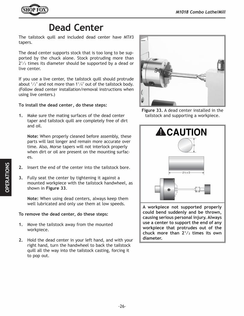
The dead center supports stock that is too long to be sup-ported by the chuck alone. Stock protruding more than 2 1⁄2 times its diameter should be supported by a dead or live center.
If you use a live center, the tailstock quill should protrude about 1⁄2'' and not more than 1 1⁄4'' out of the tailstock body. (Follow dead center installation/removal instructions when using live centers.)
Make sure the mating surfaces of the dead center taper and tailstock quill are completely free of dirt and oil.
When properly cleaned before assembly, these
parts will last longer and remain more accurate over time. Also, Morse tapers will not interlock properly when dirt or oil are present on the mounting surfac-es.
Insert the end of the center into the tailstock bore.
Fully seat the center by tightening it against a mounted workpiece with the tailstock handwheel, as shown in .
When using dead centers, always keep them well lubricated and only use them at low speeds.
Move the tailstock away from the mounted workpiece.
Hold the dead center in your left hand, and with your right hand, turn the handwheel to back the tailstock quill all the way into the tailstock casting, forcing it to pop out.
A dead center installed in the tailstock and supporting a workpiece.
A workpiece not supported properly could bend suddenly and be thrown, causing serious personal injury. Always use a center to support the end of any workpiece that protrudes out of the chuck more than 2 1⁄2 times its own diameter.
D
21⁄2 x D

-27-
A turret tool post is included with the Model M1018. This tool post will hold up to four 1⁄2" tools, as shown in
.
Having multiple tools installed in the tool post saves time by allowing you to simply loosen the lock lever and rotate to the next tool.
A spring loaded catch in the tool post helps you rotate the turret 90˚ at a time. However, the tool post can be properly secured at any rotational point by locking down the lever.
Use at least two tool post bolts to secure each tool.
Keep the tip of the tool as close as possible to the tool post and never more than 2 1⁄2 times the tool thickness from the tool post.
• Only use sharp tools.
• Make sure the top of the tool is at or just below the spindle center line. This alignment can be checked by moving the tool next to an installed dead center that has been centered to the spindle, as shown in
.
• If you use tools that must be shimmed, only use steel shims because aluminum or brass shims are soft and the tool may loosen while cutting.
Four tools mounted in the tool post.
Checking tool alignment with a dead center that has been centered to the
spindle.
Lock Lever
Left-Cutting Tool
Boring Bar
Threading Tool
Right-Cutting Tool
Shim

-28-
The Model M1018 mill spindle features an MT#3 spindle taper, which allows the drill chuck arbor to be inter-changeable with the tailstock taper.
The drill chuck and arbor are factory installed in the mill spindle, but can be installed in the tailstock for drilling operations on the lathe.
Remove the drill chuck/arbor assembly from the mill spindle by following the instructions on .
Make sure the mating surfaces of the arbor and tailstock quill are completely free of dirt and oil.
When properly cleaned before assembly, these
parts will last longer and remain more accurate over time. Also, morse tapers will not interlock properly when dirt or oil are present on the mounting surfac-es.
Insert the end of the arbor into the tailstock quill, then forcefully push it into the barrel to properly seat it in position. DO NOT hammer the arbor into the tailstock quill!
Get a small mallet and a wooden dowel to aid in removing the drill chuck/arbor assembly from the tailstock.
Place a piece of plywood across the bed ways to pro-tect the drill chuck if it pops out during removal and you don't catch it.
Tap the back edge of the drill chuck as shown in , making sure to tap it in even locations
(one side then the other) until it comes out.
Tapping drill chuck loose from tailstock.

-29-
The Model M1018 can be geared for a variety of different feed rates, so gear charts are placed on the machine to show how to set up the gear combinations for each type of carriage feed application.
• Each gear combination provides two speed options by moving the feed rate lever to either "I" or "II."
• The chart shows the variable gear positions in the arrangement as either "A" or "D." Gears are then list-ed in either the "A" or "D" row/column on the chart to show the different speeds available.
• The "T" in the diagrams represents teeth; thus, a "127T" gear has 127 teeth. The number of teeth is stamped on the face of each gear.
• The gear charts are broken into two categories—feed rates and threading rates.
There are eight feed rate speeds available for the Model M1018. The speeds are shaded in , and represent how far the carriage will move in either inches or millime-ters per every spindle revolution.
Although there are only eight speeds available, there are 16 shaded boxes in the feed rate chart because each speed setting is listed twice—once in millimeters and once in inches.
There are 9 metric threading rates and 36 standard threading rates. The threading rates are shaded in
. By arranging the gears as shown on the chart, you can set up the carriage feed for the necessary speed to cut any of the thread pitches displayed.
Feed Rate Chart.
Threading Rate Chart.

-30-
Factory gear setting.
The Model M1018 is factory set for the first column of speeds shown in the turning chart, as shown in . These instructions will walk you through an example gear change to 40 TPI so that you can gain a better under-standing of the process. For clarity, the gear positions will be labeled A, B, and C, for these instructions.
Remove the nuts on the end of the gears in positions A and C. (You may need to hold the gears with a rag to loosen the nuts.)
Loosen the cap screw below gear position C, and swing the combo gear in position B down and away from the other two gear positions.
Remove the gears in positions A and C, and note the keyed washer behind the gear in position C. Replace this washer on the shaft if it falls off.
Remove the cap screw in the middle of the combo gear in position B to remove the combo gears and the bushing. A T-nut should remain in the gear sup-port arm (see .
Insert the 72T gear in position A so the flat side of the gear is toward the inside.
Insert the 60T gear in position C so the flat side of the gear is toward the inside.
Insert the bushing that supported the 60T/120T combo gear, removed in , into the combo gear 120T/127T.
Insert the combo gear 120T/127T into position B and align the T-portion of the bushing with the slot in the support arm, then loosely attach the cap screw and washer that were removed in .
Swing the combo gear in position B up and slide it along the support arm until the 127T gear meshes with the gears in positions A and C; hold the combo gear in place and lightly snug the cap screw that mounts the combo gear, but firmly tighten the cap screw under the gear in position C.
Rotate the gears to make sure they move freely.
120T127T
60T
24T
A
B C
Cap Screw
Illustration of combo gear bushing and T-nut assembly.
Gears set for 40 TPI.
60T127T
72T
120T
A
BC

-31-
The tailstock on the Model M1018 is aligned with the headstock at the factory. However, we recommend that you take the time to ensure that the tailstock is aligned to your own desired tolerances.
Center drill a 6'' long piece of round cold rolled stock on both ends. Set it aside for use in .
Make a dead center by turning a shoulder to make a shank. Flip the piece over in the chuck and turn a 60° point, as illustrated in . As long as it remains in the chuck, the point of your center will be accurate to your spindle axis. Keep in mind that the point will have to be refinished whenever it is removed and returned to the chuck.
Place a center in your tailstock.
Attach a lathe dog to the bar stock and mount it between the centers, as shown in .
Turn approximately 0.010" off of the diameter.
Finished dead center.
Bar stock mounted on centers.
Continued on next page

-32-
NOTICE
NOTICE
Measure the workpiece with a micrometer.
• If the stock is wider at the tailstock end, the tailstock needs to be moved toward the front of the machine half the amount of the taper (see
).
• If the stock is thinner at the tailstock end, the tailstock needs to be moved toward the back of the machine by half the amount of the taper (see
).
Loosen the four tailstock mounting bolts.
Adjust the tailstock offset by the amount of the taper by turning the adjustment setscrews (see
).
Tighten the four tailstock mounting bolts.
Turn another 0.010'' off of the stock and check for taper. (Repeat as necessary until the desired amount of accuracy is achieved.)
Adjusting for headstock end taper.
Adjusting for tailstock end taper.
Adjusting tailstock offset screw.

-33-
The Model M1018 will perform many types of mill opera-tions that are beyond the scope of this manual. Many of these operations can be dangerous or deadly if performed incorrectly.
The instructions in this section are written with the under-standing that the operator has the necessary knowledge and skills to operate this machine.
If you are an inexperienced operator, we strongly recom-mend that you read books, trade articles, or seek training from an experienced combo lathe/mill operator before performing any unfamiliar operations.
The Model M1018 features an engagement hub for switch-ing back and forth between lathe and mill operations.
Open the main pulley access door.
Push in the hub shown in and turn the mill spindle by hand until you feel the gears engage the mill spindle.
• Before continuing, verify the mill is engaged by making sure the mill spindle rotates when you turn the hub or it will not move when you turn the machine .
Hub used for engaging the mill.

-34-
Before changing speeds, you must first determine the best spindle speed to use with the material and diam-eter of your cutting tool. Using this determined speed, you can then reference the spindle speed chart on the machine and set the V-belts to match that speed.
Use the chart in to determine the cutting speed for your workpiece material.
Measure the diameter of your cutting tool in inches.
Use the formula in to determine the needed RPM for your operation.
Always round to the closest RPM given on the spindle speed chart.
You have a piece of aluminum stock, and you are using a 1⁄2" diameter HSS cutting tool.
300 (SFM from chart) x 4 = 1200 1200 / 0.5" (Diameter of cutting tool) = 2400 RPM
The needed speed for this workpiece is 2400 RPM.
You have a piece of stainless steel, and you are using a 1" diameter carbide cutting tool.
60 (SFM from chart) x 2 (for carbide tool) = 120
120 (determined SFM) x 4 = 480
480 / 1" (Diameter of cutting tool) = 480 RPM
The needed speed for this workpiece is 480 RPM.
Cutting speed chart for HSS cutting tools.
Formula to determine required spindle speeds for mills.
Cutting Speeds for High Speed Steel (HSS) Cutting Tools*
Workpiece Material Cutting Speed (SFM)Aluminum & Alloys 300
Brass & Bronze 150
Copper 100
Cast Iron, soft 80
Cast Iron, hard 50
Mild Steel 90
Cast Steel 80
Alloy Steel, hard 40
Tool Steel 50
Stainless Steel 60
Titanium 50
Plastics 300-800
Wood 300-500*For carbide cutting tools, double the cutting speed. These values are a guideline only. Refer to the current edition of for more detailed information.

-35-
The Model M1018 features 14 speeds. Each speed is set with a combination of V-belt positions on the main pulleys and the mill pulleys, as illustrated in .
Refer to to determine the correct spindle speed for your cutting tool and workpiece.
Open the main pulley access door to expose the V-belts and pulleys.
Loosen the tensioning nut located just above the motor, as shown in .
Loosen the nut on the middle pulley shaft shown in .
Lift the motor and remove the lower belt from the motor pulley.
Place the upper belt in the desired position.
Place the bottom belt in the desired pulleys.
Pull tension on the upper belt with the middle pul-ley and tighten the nut loosened in .
Tighten the tensioning nut just above the motor until there is 1⁄4" deflection with moderate pressure. DO NOT over-tighten.
Remove the cover from the top of the mill to get access to the mill pulleys, as shown in .
Loosen the pulley tensioner and change belt posi-tions.
Push the pulley tensioner outward against the belt, then tighten it. The belt is properly tensioned when it has 1⁄4" deflection with moderate pressure, when pushed in the middle of the belt. DO NOT over-tighten.
Figure . Mill spindle speed chart.
Nuts used for belt tensioning or loosening.
Mill cover removed for access to the mill pulleys.
Pulley Tensioner

-36-
The quill lock lever, shown in , locks and unlocks the quill for positioning.
Quill lock lever.
Quill Lock Lever
The engagement hub, shown in , changes the spindle height control between fine downfeed and coarse downfeed.
Push the engagement knob in and slowly move the fine downfeed knob to engage the gears. The fine downfeed knob will now be activated for use and the coarse down-feed handle will be deactivated.
Pull the engagement knob out and slowly move the coarse downfeed handle to engage the gears. The coarse downfeed handle will now be activated for use and the fine downfeed knob will be deactivated.
To rotate the mill head out of the way for lathe opera-tions, loosen the head lock shown in , push the mill head where desired, and lock the head in place with the head lock.
To raise or lower the mill head, loosen the head lock, rotate the elevator wheel ( to the desired height, then lock the head in place with the head lock.
Downfeed controls.
Fine Downfeed Knob
Engagement Knob
Coarse Downfeed Handle
Mill head height wheel.
Elevator Wheel
Head Lock
Performing this procedure is essential to ensure long-lasting and reliable performance. Complete this process only after you have familiarized yourself with all instructions in this manual and have performed the on .
Follow the lathe break-in instructions on if you have not already done so.
Working from the slowest speed to the fastest, run the mill at each speed for ten minutes.

-37-
The Model M1018 features an MT#3 spindle taper which allows the drill chuck arbor to be interchangeable with the tailstock taper. The drill chuck has a capacity of 1⁄16"–1⁄2" (1.5mm–13mm).
Remove the plastic cap shown in .
Hold the drill chuck with one hand, and using a wrench, unscrew the drawbar three turns.
Lock the quill with the quill lock lever.
Using a rubber mallet or other soft-faced hammer, tap the end of the drawbar as shown in .
Plastic cap for accessing drawbar.
Plastic Cap
Tapping drawbar to loosen it.
Drawbar
When the arbor is loose, hold the drill chuck and completely unscrew the drawbar. The drill chuck/arbor assembly should now slide out of the spindle.
To install the drill chuck/arbor assembly, do these steps:
Carefully clean the surface of the collet and spindle taper of debris, oil, or grease of any kind.
Insert the arbor into the spindle and press it up firmly to seat the taper.
Remove the drawbar cap and finger tighten the drawbar until the arbor is secure in the spindle, then tighten the drawbar with a wrench without over-tight-ening.
Over-tightening makes removal much harder and causes unnecessary wear to the drawbar threads, collet and spindle taper.

-38-
Regular periodic maintenance on your ®
Model M1018 will ensure its optimum performance. Make a habit of inspecting your machine each time you use it.
Loose mounting bolts. Worn switch or safety shut-off components. Worn or damaged cords and plugs. Damaged V-belt. Any other condition that could hamper the safe
operation of this machine.
The Model M1018 will function best when it is clean and well lubricated. Take the time to wipe down and oil the machine before each use. We recommend using ISO 68 or SAE 20W non-detergent machine oil unless otherwise specified.
Ball fittings, shown in , should be lubri-cated daily and require the use of an oil gun. Wipe the ball fitting clean, depress it with the tip of the gun, and squirt a little oil under pressure. Make sure to clean the machine after each lubrication.
Ball fitting lubrication points.
Downfeed ball fittings.
Downfeed Ball Fittings
• Lubricate spindle bearings through the ball fittings shown in .
• Lubricate the ball fittings shown in .• Lubricate external gears (see ).• Lubricate tailstock ball fittings shown in .• Lubricate the lead screw directly.• Lubricate the apron and cross slide ways.
• Change gearbox oil.

-39-
Wipe clean and apply lubrication directly to the dovetail ways of the apron and cross slide.
Apply lithium-based grease to the teeth of the end gears ( after assembly or each day. Avoid getting grease on the belt or pulleys when lubricating. Also, remove the combo gear, and apply a dab of grease to the bushing.
Lubrication for the bearings occurs as the machine runs and oil circulates from the gear box. However, the bear-ings should also be lubricated through the ball fittings indicated by the arrows in .
Apply oil in the location shown in .
Clean the lead screw and lubricate it directly.
The oil in the headstock should be changed after the first two hours of use, then every six months, depending on usage. We recommend using a light-weight, non-detergent 20W gear oil.
To drain the oil in the gear box, remove the change gear directly under the spindle, remove the cap screw indi-cated in , and place a tray under the drain hole to collect the waste oil.
To add oil, remove the oil fill plug from the back of the machine (shown in ), and add oil until full on the sight glass.
Spindle bearing ball fittings.
Gearbox drain plug, external gears, and bushing.
Tailstock lubrication points.
Gearbox Drain Plug
Oil fill plug.
Oil Fill Plug
Bushing

-40-
This section covers the most common service adjustments or procedures that may need to be made during the life of your machine.
If you require additional machine service not included in this section, please contact Woodstock International Technical Support at (360) 734-3482 or send e-mail to: [email protected].
The cross-slide gib, the compound slide gib, and the apron gib can be adjusted on the Model M1018.
The gib on the cross-slide is adjusted by tightening or loosening the two outside setscrews located on the right hand side of the slide, as shown in . The large setscrew in the middle is used to lock the cross slide in place during machining operations. Before adjusting the gib screws, loosen this setscrew.
The gib is held in place by the setscrews. DO NOT over tighten. The gib is properly adjusted when a slight drag is detected while turning the hand crank. This drag should be evenly distributed among the setscrews, so adjust each until a slight drag is detected while the hand crank is turned. The large setscrew in the middle of the slide can be tightened to lock the slide in place.
Adjusting cross-slide gib.

-41-
The gib on the compound has two setscrews to maintain tension on the slide. To adjust, loosen/tighten the set-screws as needed (see ) until a slight drag is felt when moving the compound hand crank.
There are two setscrews that tension the saddle gib. Before making adjustments to the saddle gib, ensure that the front lock lever is loose by turning it counterclock-wise (see ).
It is important the setscrews are tightened evenly. A slight drag should be detected while turning the hand crank at the end of the lathe.
Adjusting compound gib.
Adjusting saddle gib.

-42-

-43-
This section covers the most common symptoms.
Motor will not start. 1. Low voltage.2. Open circuit in motor or loose
connections.3. Faulty start capacitor.
1. Check power supply for proper voltage.2. Inspect all wiring for loose or open connections.
3. Replace start capacitor.
Fuses or circuit breakers trip open.
1. Short circuit in line cord or plug.
2. Short circuit in motor or loose connections.
3. Incorrect fuses or circuit breakers in power supply.
1. Inspect cord or plug for damaged insulation and shorted wires, and replace extension cord.
2. Inspect all connections on motor for loose or shorted terminals or worn insulation.
3. Install correct fuses or circuit breakers.
Motor overheats. 1. Motor overloaded. 1. Reduce load on motor.
Tool slips in collet. 1. Collet is not fully drawn up into spindle taper.
2. Wrong size collet.
3. Debris in collet or in spindle taper.
4. Taking too big of a cut.
1. Snug up drawbar. 2. Measure tool shank diameter and match with
appropriate diameter collet.3. Remove all oil and debris from collet and spindle
taper.4. Lessen depth of cut and allow chips to clear.
Breaking tools, cutters. 1. RPM and or feed rate is too fast.
2. Cutter getting too hot.
3. Taking too big of a cut.
1. Use the table on 34 to set correct RPM and feed rates.
2. Lubricate the cutter with the correct cutting fluid for the application.
3. Lessen depth of cut and allow chips to clear.
Machine is loud when cutting. Overheats or bogs down in the cut.
1. Excessive depth of cut.2. Dull cutting tools.
1. Decrease depth of cut.2. Use sharp cutters.
Workpiece vibrates or chatters during operation.
1. Table locks not tight. 2. Spindle lock not tight.3. Workpiece not securely clamped
to table or into mill vice.4. RPM and feed rate too high.
1. Tighten down table locks.2. Tighten spindle lock.3. Check that clamping is tight and sufficient for the
job. Make sure mill vice is tight to the table.4. Use appropriate RPM and feed for the job.
Table hard to move. 1. Table locks are tightened down.2. Chips have loaded up on bedways.
3. Bedways are dry and in need of lubrication.
4. Longitudinal stops are interfering.
5. Gibs are too tight.
1. Check to make sure table locks are fully released.2. Frequently clean away chips that load up during
milling operations.3. Lubricate bedways and handles.
4. Check to make sure that stops are floating and not hitting the center stop.
5. Loosen gib screw(s).
Bad surface finish. 1. Wrong RPM or feed rate.
2. Dull cutter or poor cutter selec-tion.
1. Use the table on 34 to set correct RPM and feed rates.
2. Sharpen cutter or select a better cutter for the intended operation.

-44-

-45-
Ref Part # Description Ref Part # Description
1 XM1018001 MOTOR 29 XM1018029 CHANGE GEAR 25T1-1 XM1018001-1 MOTOR FAN COVER 30 XM1018030 CHANGE GEAR 27T1-2 XM1018001-2 MOTOR FAN 31 XM1018031 CHANGE GEAR 30T1-3 XM1018001-3 CAPACITOR COVER 32 XM1018032 CHANGE GEAR 33T1-4 XPC035A CAPACITOR 35MFD 250VAC 33 XM1018033 CHANGE GEAR 36T1-5 XM1018001-5 CAPACITOR COVER 34 XM1018034 CHANGE GEAR 42T1-6 XPC250 CAPACITOR 250MFD 125VAC 35 XM1018035 CHANGE GEAR 48T1-7 XM1018001-7 WIRING BOX 36 XM1018036 CHANGE GEAR 60T2 XPSS20M SET SCREW M8-1.25 X 8 37 XM1018037 CHANGE GEAR 75T3 XM1018003 PULLEY 38 XM1018038 CHANGE GEAR 120T4 XPK23M KEY 5 X 5 X 25 39 XM1018039 DUPLEX GEAR 60/120T5 XPB07M HEX BOLT M8-1.25 X 25 40 XM1018040 DUPLEX GEAR 125/127T6 XPLW04M LOCK WASHER 8MM 41 XM1018041 STRAIN RELIEF 15MM7 XPW01M FLAT WASHER 8MM 42 XM1018042 PLASTIC HOUSING8 XPN02M HEX NUT M10-1.5 43 XM1018043 SWITCH ASSEMBLY9 XM1018009 BALL FACE WASHER 44 XM1018044 SAFETY SWITCH10 XM1018010 CONE FACE WASHER 45 XM1018045 SPACER11 XM1018011 MOTOR PEDESTAL 46 XM1018046 SWITCH COVER12 XPSB11M CAP SCREW M8-1.25 X 16 47 XM1018047 STOP/RESET SWITCH13 XM1018013 MOTOR BRACKET 48 XM1018048 INDICATOR LIGHT14 XM1018014 COTTER PIN 3 X 16 49 XPS25M PHLP HD SCR M4-.7 X 3515 XM1018015 CLEVIS PIN 50 XM1018050 LIGHT HOLDER16 XM1018016 MOVABLE JOINT 51 XPS07M PHLP HD SCR M4-.7 X 817 XM1018017 CLEVIS PIN 52 XM1018052 CONNECTION BUS18 XM1018018 SPECIAL BOLT 53 XM1018041 STRAIN RELIEF 15MM19 XM1018019 T-KEY 54 XM1018054 MOUNTING BRACKET20 XM1018020 GEAR BRACKET 55 XM1018055 COVER21 XPW04M FLAT WASHER 10MM 56 XPS51M PHLP HD SCR M4-.7 X 3022 XM1018022 T-COLLAR 57 XM1018057 STRAIN RELIEF 10MM23 XPW03M FLAT WASHER 6MM 58 XPWRCRD110L POWER CORD 110V LONG24 XPSB29M CAP SCREW M6-1 X 40 59 XM1018059 FLEXIBLE CONDUIT25 XPW04M FLAT WASHER 10MM 60 XM1018060 GUARD PLATE26 XPW03M FLAT WASHER 6MM 61 XPHTEK5M TAP SCREW M4 X 1227 XPSB07M CAP SCREW M6-1 X 30 62 XM1018062 HEADSTOCK BOX28 XM1018028 CHANGE GEAR 24T 63 XM1018063 STRAIN RELIEF 13MM

-46-

-47-
Ref Part # Description Ref Part # Description
101 XM1018101 PIN 8 X 30 133 XPFH30M FLAT HD SCR M5-.8 X 8102 XM1018102 LINK BOARD 134 XPVM29 V-BELT 3L290103 XPRP03M ROLL PIN 5 X 20 135 XM1018135 PULLEY104 XM1018104 PIN 12 X 40 136 XM1018136 SHAFT105 XM1018105 COMPRESSION SPRING 137 XM1018137 COVER106 XM1018106 STEEL BALL 5MM 138 XPS07M PHLP HD SCR M4-.7 X 8107 XM1018107 LEVER BASE 139 XPW05M FLAT WASHER 4MM108 XPRP03M ROLL PIN 5 X 20 140 XM1018140 BEARING 1000900109 XPSS14M SETSCREW M8-1.25 X 12 141 XM1018141 COLLAR110 XM1018110 LEVER 142 XPSB26M CAP SCREW M6-1 X 12111 XM1018111 HANDLE KNOB M10-1.5 143 XM1018143 OIL FILL PLUG112 XPRP44M ROLL PIN 3 X 10 144 XM1018144 PULLEY BRACKET GASKET113 XM1018113 KEYED DUPLEX GEAR 145 XM1018145 PULLEY BRACKET114 XPR03M EXT RETAINING RING 12MM 146 XM1018146 SHAFT115 XM1018115 SLEEVE 147 XM1018147 SLEEVE116 XM1018116 OIL�SEAL�BOARD�GASKET 148 XM1018148 DUPLEX GEAR117 XM1018117 OIL SEAL 149 XM1018149 PINNED DUPLEX GEAR118 XM1018118 OIL SEAL BOARD 150 XM1018150 KEYED GEAR119 XPSB15M CAP SCREW M5-.8 X 20 151 XM1018151 SHAFT120 XPK34M KEY 5 X 5 X 20 152 XPK19M KEY 5 X 5 X 14121 XM1018121 SHAFT 153 XM1018153 PIN122 XPK05M KEY 4 X 4 X 10 154 XPB31M HEX BOLT M10-1.75 X 40123 XM1018123 SLEEVE 155 XM1018155 SIGHT GLASS124 XM1018124 ROUND COVER GASKET 156 XM1018156 OILER 6MM125 XM1018125 ROUND COVER 157 XM1018157 END BUSHING126 XPSB50M CAP SCREW M5-.8 X 10 158 XM1018158 SHIFT BRACKET127 XPN08M HEX NUT M10-1.25 159 XPN06M HEX NUT M5-.8128 XPLW06M LOCK WASHER 10MM 160 XPSS05M SET SCREW M5-.8 X 10129 XPW04M FLAT WASHER 10MM 161 XM1018161 END BUSHING130 XM1018130 HOUSING 162 XPEC12M E-CLIP 12MM131 XM1018131 SEAL RING 163 XPFH07M FLAT HD SCR M5-.8 X 10132 XM1018132 COVER 164 XM1018164 SPECIAL�SCREW�M5-.8�x�18

-48-

-49-
Ref Part # Description Ref Part # Description
201 XM1018201 CLUTCH 220 XM1018220 T-KEY202 XPK70M KEY 8 X 8 X 12 221 XPR13M EXT RETAINING RING 65MM203 XM1018203 CLUTCH END 222 XP6013 BALL BEARING 6013204 XM1018204 TAB WASHER 30MM 223 XM1018223 BEARING PEDESTAL205 XM1018205 SPANNER NUT 30MM 224 XPS07M PHLP HD SCREW M4-.7 X 8206 XPS19M PHLP HD SCR M5-.8 X 6 225 XPSS05M SET SCREW M5-.8 X 10207 XM1018207 ENGAGEMENT HUB 226 XM1018226 SPINDLE GEAR208 XM1018208 BEARING D2007107 227 XM1018227 SEAL WASHER209 XM1018209 BUSHING 228 XM1018228 BEARING WASHER210 XM1018210 SLEEVE 229 XPK70M KEY 8 X 8 X 12211 XM1018211 BEVEL GEAR 230 XPK91M KEY 8 X 8 X 22212 XM1018212 BEARING D2007107 231 XPSB26M CAP SCREW M6-1 X 12213 XM1018213 BEARING PEDESTAL 232 XM1018232 SPINDLE214 XPSB95M CAP SCREW M5-.8 X 30 233 XM1018233 3-JAW CHUCK215 XM1018106 STEEL BALL M5 234 XM1018234 CHUCK KEY216 XM1018105 COMPRESSION SPRING 235 XM1018235 INT CHUCK JAW (SET OF 3)217 XPVM26 V-BELT 3L260 236 XM1018236 EXT CHUCK JAW (SET OF 3)218 XM1018218 PULLEY 237 XPSS20M SET SCREW M8-1.25 X 8219 XPSB68M CAP SCREW M6-1 X 8

-50-

-51-
Ref Part # Description Ref Part # Description
301 XM1018301 BODY 336 XM1018336 HALF NUT 302 XM1018302 CLUTCH B 337 XM1018337 HALF NUT BASE303 XM1018303 CLUTCH A 338 XM1018338 HALF NUT BRACKET 304 XPRP25M ROLL PIN 5 X 21 339 XPSS14M SET SCREW M8-1.25 X 12 305 XM1018305 SLEEVE (LEFT) 340 XM1018340 LONG LEAD SCREW306 XM1018306 SHAFT 341 XM1018341 STEEL PIN307 XPK69M KEY 4 X 4 X 12 342 XP8103 THRUST BEARING 8103308 XM1018308 ECCENTRIC PIN 343 XM1018343 CONE PIN309 XM1018309 COVER 344 XM1018344 LEAD SCREW BRACKET310 XM1018310 LEVER 345 XM1018345 SCALE RING311 XPSS04M SET SCREW M6-1 X 12 346 XM1018346 SPANNER NUT 14MM312 XPSB12M CAP SCREW M8-1.25 X 40 347 XM1018347 BALL CRANK HANDLE313 XM1018313 STEEL BALL 6.5MM 348 XM1018348 TAPER PIN314 XM1018314 COMPRESSION SPRING 349 XM1018349 HANDWHEEL HANDLE315 XM1018315 LEVER BASE 350 XPN25M HEX NUT ACORN M10-1.5316 XPSS11M SET SCREW M6-1 X 16 351 XM1018351 HANDWHEEL 317 XM1018317 OILER 352 XM1018352 SCALE RING318 XM1018318 LINK BASE 353 XPRP06M ROLL PIN 5 X 24 319 XPEC12M E-CLIP 12MM 354 XM1018354 LEAD SCREW BRACKET320 XM1018320 SLEEVE (RIGHT) 355 XM1018355 HANDLE SCREW 321 XPK10M KEY 5 X 5 X 12 356 XPSS16M SET SCREW M8-1.25 X 10322 XM1018322 PIN 357 XM1018357 LOCKING PIN 323 XPSB37M CAP SCREW M6-1.0 X 50 358 XM1018358 LONGITUDINAL SLIDE 324 XM1018324 HANDLE KNOB M6-1 359 XM1018359 GIB325 XM1018325 LEVER 360 XPK48M KEY 4 X 4 X 20 326 XM1018326 LEVER BASE 361 XM1018361 CROSS LEAD SCREW327 XM1018327 SPRING PIN 362 XM1018362 CROSS SLIDE NUT328 XM1018328 COMPRESSION SPRING 363 XM1018363 GIB329 XPSS17M SET SCREW M8-1.25 X 6 364 XM1018364 CROSS SLIDE 330 XM1018330 LIFTING PIN 365 XM1018365 RIVET331 XM1018331 COTTER PIN 5 X 36 366 XPW04M FLAT WASHER 10MM332 XPSB33M CAP SCREW M5-.8 X 12 367 XM1018367 INDEX PLATE333 XM1018333 COVER 368 XPSB11M CAP SCREW M8-1.25 X 16334 XM1018334 PIN BASE 369 XM1018369 INDEX PLATE335 XM1018335 CAP SCREW 370 XM1018370 LEAD SCREW SLEEVE

-52-

-53-
Ref Part # Description Ref Part # Description
401 XM1018401 DRAW BAR 454 XPRP16M ROLL PIN 3 X 25403 XPSB24M CAP SCREW M5-.8 X 16 455 XM1018455 STAR KNOB 12MM PINNED404 XPLW01M LOCK WASHER 5MM 456 XM1018456 LEVER405 XPW02M FLAT WASHER 5MM 457 XM1018457 PIN406 XM1018406 BEVEL GEAR 458 XM1018458 WORM SHAFT407 XM1018407 KEYED COMP WASHER 459 XM1018459 OILER408 XPK101M KEY 6 X 6 X 14 460 XPSS06M SET SCREW M8-1.25 X 16409 XM1018409 DRIVING SHAFT 461 XM1018461 COMP WASHER410 XPK43M KEY 8 X 8 X 45 462 XM1018462 STUD411 XPFH07M FLAT HD SCR M5-.8 X 10 463 XM1018463 LOCK LEVER412 XPSS65M SET SCREW M16-2 X 20 465 XPSS24M SET SCREW M5-.8 X 25413 XM1018413 LOCK BOLT SEAL 466 XM1018466 FLAT COILED SPRING414 XM1018414 LOCKING PIN 467 XM1018467 SPRING HOUSING COVER415 XM1018415 DRILL/MILL HOUSING 468 XM1018468 PULLEY SHELL (BOTTOM)416 XPFH07M FLAT HD SCR M5-.8 X 10 469 XPW01M FLAT WASHER 8MM417 XM1018417 BEARING NUT 35MM 470 XPS76M PHLP HD SCR M8-1.25 X 12418 XP6007 BALL BEARING 6007 471 XM1018471 SHAFT419 XP6008 BALL BEARING 6008 472 XM1018472 TIGHTENER BOARD420 XPSB04M CAP SCREW M6-1 X 10 473 XM1018473 TIGHTENER SHAFT421 XM1018421 PLATE 474 XM1018474 PULLEY BRACKET422 XM1018422 ROTATION BASE 475 XPW01M FLAT WASHER 8MM423 XM1018423 HANDLE KNOB M6-1 476 XPLW04M LOCK WASHER 8MM424 XM1018424 LEVER 477 XM1018477 SHELL BOLT425 XPSB13M CAP SCREW M8-1.25 X 30 478 XPB16M HEX BOLT M5-.8 X 24426 XM1018426 STEEL BALL 479 XPK23M KEY 5 X 5 X 25427 XM1018427 BEARING 2007107 480 XM1018480 BELT TIGHTENER428 XM1018428 HOLLOW SHAFT 481 XM1018481 ROLLER429 XM1018429 BEARING 2007106 482 XPR24M INT RETAINING RING 42MM430 XM1018430 BEARING WASHER 30MM 483 XP6104 BALL BEARING 6104431 XM1018431 SPANNER NUT M30-1.5 484 XM1018484 BEARING BRACKET433 XPSS08M SET SCREW M4-.7 X 5 485 XPSB24M CAP SCREW M5-.8 X 16434 XM1018434 GEAR SHAFT 486 XM1018486 COLLAR435 XPK101M KEY 6 X 6 X 14 487 XP6108 BALL BEARING 6108436 XPSS03M SET SCREW M6-1 X 8 488 XPR01M EXT RETAINING RING 10MM437 XM1018437 COLLAR 489 XPR34M EXT RETAINING RING 40MM438 XM1018438 FEED BOX HOUSING 490 XPW01M FLAT WASHER 8MM439 XM1018439 WORM GEAR 491 XM1018491 PULLEY440 XPRP27M ROLL PIN 5 X 28 492 XM1018492 COVER441 XM1018441 CLUTCH 493 XM1018493 PIPE442 XM1018442 PIN 494 XM1018494 PULLEY SHELL (TOP)443 XM1018443 SCALE RING 495 XPW01M FLAT WASHER 8MM444 XM1018444 DRILL/MILL SHAFT 496 XM1018496 STAR KNOB M8-1.25445 XM1018445 SEAL 497 XPVM29 V-BELT M-29 3L290446 XM1018446 DRILL/MILL SHAFT COVER 498 XM1018498 PULLEY447 XPSS05M SET SCREW M5-.8 X 10 499 XPW02M FLAT WASHER 5MM448 XM1018448 ROUND KNOB M10-1.5 500 XPLW01M LOCK WASHER 5MM449 XPSS58M SET SCREW M6-1 X 18 501 XPSB15M CAP SCREW M5-.8 X 20450 XM1018450 COLLAR 502 XM1018502 DRILL CHUCK B-16, 1/16"-1/2"451 XM1018451 LEAF SPRING 503 XM1018503 ARBOR MT#3 X B-16452 XM1018452 LEVER 504 XM1018504 RIVET453 XM1018453 HANDLE KNOB M8-1.25 505 XM1018505 GRADUATED DIAL SCALE

-54-

-55-
Ref Page # Description Ref Page # Description
601 XPW04M FLAT WASHER 10MM 620 XM1018620 OILER602 XM1018602 LOCKING HUB 621 XM1018621 LEAD SCREW NUT603 XM1018603 LEVER 622 XM1018622 LEAD SCREW604 XM1018604 HANDLE KNOB M10-1.5 623 XM1018623 LEAD SCREW BRACKET605 XM1018605 SQ HD BOLT M8-1.25 X 25 624 XM1018624 HAND CRANK606 XM1018606 TOOL POST 625 XPRP02M ROLL PIN 3 X 16607 XM1018607 HOLLOW SET PIN 626 XPN03M HEX NUT M8-1.25608 XM1018608 COMPRESSION SPRING 627 XPW01M FLAT WASHER 8MM609 XM1018609 TOOL POST BASE 628 XPSS31M SET SCREW M5-.8 X 8610 XM1018610 BLOCK 629 XM1018629 DOWN SLIDE611 XPS02M PHLP HD SCR M4-.7 X 12 630 XM1018630 SCALE612 XM1018612 MOUNTING BOLT 631 XM1018631 T-BOLT M8-1.25 X 25613 XM1018613 VISE BLOCK 632 XM1018632 BASE614 XPSB26M CAP SCREW M6-1 X 12 633 XM1018633 SCALE615 XM1018615 GIB 634 XM1018634 T-BOLT M10-1.5 X 28616 XPSS24M SET SCREW M5-.8 X 25 635 XPW04M FLAT WASHER 10MM617 XM1018617 LOCKING PIN 636 XPN02M HEX NUT M10-1.5618 XPSB09M CAP SCREW M5-.8 X 17 637 XM1018637 RIVET619 XM1018619 UPSLIDE 638 XM1018638 TOOL POST WRENCH

-56-

-57-
Ref Page # Description Ref Page # Description
701 XM1018701 HANDLE KNOB M6-1 723 XM1018723 HANDLE KNOB M10-1.5702 XM1018702 LEVER 724 XM1018724 BRACKET703 XM1018703 LOCK HUB 725 XM1018725 DIAL 704 XPN25M HEX NUT ACORN M10-1.5 726 XM1018726 HANDWHEEL 705 XM1018705 LOCK PIN 727 XPW04M FLAT WASHER 10MM706 XPSS06M SET SCREW M8-1.25 X 16 728 XM1018728 HANDWHEEL HANDLE707 XPSS21M SETSCREW M8-1.25 X 25 729 XPK102M KEY 4 X 4 X 18708 XM1018708 TAILSTOCK BASE 730 XM1018730 FEED SCREW709 XM1018709 GIB 731 XPRP49M ROLL PIN 5 X 25710 XM1018710 TAILSTOCK BODY 732 XM1018732 COLLAR711 XPB31M HEX BOLT M10-1.5 X 40 733 XM1018733 DEAD CENTER712 XPSS51M SETSCREW M4-.7 X 8 734 XPAW04M ALLEN WRENCH 4MM713 XM1018713 T-KEY 735 XPAW05M ALLEN WRENCH 5MM714 XM1018714 TAILSTOCK QUILL 736 XPAW08M ALLEN WRENCH 8MM715 XM1018715 FEED NUT 737 XPW04M FLAT WASHER 10MM716 XM1018716 OIL CUP 738 XM1018738 INDICATOR717 XM1018717 LOCK BUSHING (BOTTOM) 739 XM1018739 ADJUSTING STUD718 XM1018718 LOCK BUSHING (TOP) 740 XM1018740 KEY719 XM1018719 DOUBLE SCREW BOLT 741 XM1018741 SET SCREW M12-1.5 X 65
720 XPW04M FLAT WASHER 10MM 742 XM1018742 SCALE721 XM1018721 LOCKING HUB NUT 743 XM1018743 RIVET722 XM1018722 LOCK LEVER 744 XM1018744 INDICATOR


CUT
ALO
NG
DO
TTED
LIN
E
Name ___________________________________________________________________________________
Street __________________________________________________________________________________
City _________________________ State ___________________________Zip ________________________
Phone # ______________________ Email___________________________Invoice # ___________________
Model #_________Serial #______________Dealer Name__________________Purchase Date___________
How did you learn about us? _____ Advertisement _____ Friend ____ Local Store _____ Mail Order Catalog _____ Website ____ Other:
How long have you been a woodworker/metalworker? _____ 0-2 Years _____ 2-8 Years ____ 8-20 Years _____ 20+ Years
How many of your machines or tools are ? _____ 0-2 _____ 3-5 ____ 6-9 _____ 10+
Do you think your machine represents a good value? _____ Yes ____ No
Would you recommend products to a friend? _____ Yes ____ No
What is your age group? _____ 20-29 _____ 30-39 ____ 40-49 _____ 50-59 _____ 60-69 ____ 70+
What is your annual household income? _____ $20,000-$29,000 _____ $30,000-$39,000 ____ $40,000-$49,000 _____ $50,000-$59,000 _____ $60,000-$69,000 ____ $70,000+
Which of the following magazines do you subscribe to?
Comments:
____ Cabinet Maker____ Family Handyman____ Hand Loader____ Handy____ Home Shop Machinist____ Journal of Light Const.____ Live Steam____ Model Airplane News____ Modeltec____ Old House Journal
____ Popular Mechanics____ Popular Science____ Popular Woodworking____ Practical Homeowner____ Precision Shooter____ Projects in Metal____ RC Modeler____ Rifle____ Shop Notes____ Shotgun News
____ Today’s Homeowner____ Wood____ Wooden Boat____ Woodshop News____ Woodsmith____ Woodwork____ Woodworker West____ Woodworker’s Journal____ Other:

TAPE ALONG EDGES--PLEASE DO NOT STAPLE
FOLD ALONG DOTTED LINE
FOLD ALONG DOTTED LINE
PlaceStampHere

