m02 kibb5087 09 se c02 -...
TRANSCRIPT

U N I T O N E Arbor and Shop Presses
U N I T T W O Work-Holding and Hand Tools
U N I T T H R E E Hacksaws
U N I T F O U R Files
U N I T F I V E Hand Reamers
U N I T S I X Identification and Uses of Taps
U N I T S E V E N Tapping Procedures
U N I T E I G H T Thread-Cutting Dies and Their Uses
U N I T N I N E Off-Hand Grinding
35
Hand ToolsS E C T I O N B
M02_KIBB5087_09_SE_C02.qxd 1/26/09 5:29 PM Page 35REVISED

36 SECTION B HAND TOOLS
Our ability to make and use tools has been directlyresponsible for all technical advancement. Prior to the
development of advanced metalworking, natural materialssuch as stone, flint, and wood provided the only tool mate-rials. When metals and metalworking techniques becamebetter established, tool development advanced greatly,which led to the many fine tools of today. A study of toolsmust logically begin with those used by hand for hand oper-ations. In this section you will be introduced to the basiccomplement of hand tools used in all branches of mechan-ical technology.
Work-holding devices were not developed in earlytimes. Artisans in many Middle Eastern and Asian countriesstill preferred to use their feet instead of a vise to hold theworkpiece. Machinists today tend to take the bench vise forgranted, seldom realizing that they could hardly get alongwithout it.
Arbor presses and hydraulic shop presses are useful andpowerful shop tools. If they are used incorrectly, however,they can be hazardous to the operator, and workpieces can beruined.
Noncutting tools such as screwdrivers, pliers, andwrenches should be properly identified. It is impossible torequest a particular tool from the toolroom without knowingits correct name.
Cutting hand tools such as hacksaws, files, hand reamers,taps, and dies are important to a machinist. In this sectionyou will also be introduced to the pedestal grinder and itsimportant functions in the machine shop.
The units that follow in this section will instruct you inthe identification, selection, use, and safety of these impor-tant hand tools and hand-operated machines.
C A U T I O N
Hand Tool Safety Tools described in this section arequite safe if they are used as they were designed to beused. For example, a screwdriver is not meant to be achisel, and a file is not meant to be a pry bar. Wrenchesshould be the correct size for the nut or bolt head sothey will not slip. Inch measure wrenches should not beused on metric fasteners. When a wrench slips, skinnedknuckles are often the result. Hacksaws should be heldby the handle, not the frame. Fingers wrapped aroundthe frame tend to get mashed. Files should never beused without a handle because the tang can severelydamage the hand or wrist. Safety precautions are notedthroughout this section for using other equipment, suchas presses and pedestal grinders.
M02_KIBB5087_09_SE_C02.qxd 1/26/09 5:29 PM Page 36REVISED

O B J E C T I V E S
U N I T O N E
Arbor and Shop Presses
The arbor press and the small shop press are commonsights in most machine shops. It would be difficult indeed
to get along without them. You will find these tools extremelyuseful when you know how to use them, but if you are notinstructed in their use, they can be dangerous to you anddestructive to the workpiece.
After completing this unit, you should be able to:
! Install and remove a bronze bushing using an arborpress.
! Press on and remove a ball bearing from a shaft onan arbor press using the correct tools.
! Press on and remove a ball bearing from a housingusing an arbor press and correct tooling.
! Install and remove a mandrel using an arbor press.
! Install and remove a shaft with key in a hub using thearbor press.
37
Figure B-1 Small hydraulic shop press.
TYPES OF PRESSES
The arbor press is an essential piece of equipment in thesmall machine shop. Without it a machinist would be forcedto resort to the use of a hammer or sledge to make any forcedfit, a process that could easily damage the part.
Two basic types of hand-powered arbor presses aremanufactured and used: the hydraulic (Figure B-1) and themechanical (Figure B-2). The lever gives a “feel” or a sense ofpressure applied, which is not possible with the power-drivenpresses. This pressure sensitivity is needed when small deli-cate parts are being pressed so that a worker will know whento stop before collapsing the piece.
USES OF PRESSES
The major uses of the arbor press are installing and removingbushings, installing and removing ball and roller bearings(Figure B-3), pressing shafts into hubs (Figure B-4), pressingmandrels into workpieces, straightening and bending, andbroaching keyseats. A keyseat is an axially located rectangulargroove in a shaft or hub. Keyseats in shafts are cut in milling
M02_KIBB5087_09_SE_C02.qxd 1/26/09 5:29 PM Page 37REVISED

38 SECTION B HAND TOOLS
Figure B-3 Roller bearing being removed from axle.
machines, but keyseats in hubs of gears, sprockets, or otherdriven members must be either broached or cut in a keyseater,a special type of vertical shaper.
PROCEDURES
Installing BushingsA bushing is a short metal tube, machined inside and outto precision dimensions, and usually made to fit into a bore,or accurately machined hole. Many kinds of bushings areused for various purposes and are usually installed with aninterference fit or press fit. This means that the bushing isslightly larger than the hole into which it is pressed. Theamount of interference will be considered in greater detail ina later unit. There are many bushings made of various mate-rials, including bronze and hardened steel, but they all haveone thing in common: they must be lubricated with high-pressure lube before they are pressed into the bore. Oil is notused, as it will simply wipe off and cause the bushing to seizethe bore. Seizing is the condition in which two unlubricatedmetals tend to weld together under pressure. In this case itmay cause the bushing to be damaged beyond repair.
The bore should always have a strong chamfer, that is,an angled or beveled edge, since a sharp edge would cut into
Figure B-4 Shaft being pressed into hub.
Figure B-2 Simple ratchet floor-type arbor press (Dake
Corporation).
M02_KIBB5087_09_SE_C02.qxd 1/26/09 5:29 PM Page 38REVISED

UNIT ONE ARBOR AND SHOP PRESSES 39
Press ramPress ram
Chamfer
(a) (b)
Figure B-5 (a) Bushing being pressed where bore is notchamfered and bushing is misaligned; (b) bushing beingpressed into correctly chamfered hole in correct alignment.
the bushing and damage it (Figure B-5). The bushing shouldalso have a long tapered chamfer or start so it will not dig inand enter misaligned. Bushings are prone to go in crooked,especially hardened steel bushings, if there is a sharp edge.Care should be taken to see that the bushing is straight enter-ing the bore and that it continues into the bore in properalignment. This should not be a problem if the tooling isright, that is, if the end of the press ram is square and if it isnot loose and worn. The proper bolster plate should also beused under the part so that it cannot tilt out of alignment.Sometimes, special tooling is used to guide the bushing(Figure B-6). When the workpiece is resting on a solid bolsterplate, only the pressure needed to force the bushing into placeshould be applied, especially if the bushing is longer than thebore length. Excessive pressure might distort and collapse thebushing and cause it to be undersized (Figure B-7). However,
some bolster plates provide various size holes so that a bush-ing or part can extend through. In that case, the press ram canbe brought to the point where it contacts the workpiece, andthere is no danger of upsetting the bushing.
Ball and Roller BearingsBall and roller bearings pose special problems when theyare installed and removed by pressing. This is because thepressure must be applied directly against the race and notthrough the balls or rollers, since this could destroy thebearing. Frequently, when removing ball bearings from ashaft, the inner race is hidden by a shoulder and cannot besupported in the normal way. In this case, a special toolcalled a bearing puller is used (Figure B-8). On the innerand outer races, bearings may be installed by pressing onthe race with a steel tube of the proper diameter. As withbushings, high-pressure lubricant should be used.
Sometimes there is no other way to remove an old ballbearing except by exerting pressure through the balls. Whenthis is done, there is a real danger that the race may be violent-ly shattered. In this case, a scatter shield must be used. A scat-ter shield is a heavy steel tube about 8 to 12 in. long set up tocover the work. The shield is placed around the bearing duringpressing to keep shattered parts from injuring the operator. Itis a good safety practice to always use a scatter shield when ballbearings are removed from a shaft by pressing. Safety glassesshould be worn during all pressing operations.
Bores and ShaftsHoles in the hubs of gears, sprockets, and other machine partsare also frequently designed for a force fit. In these instances,there is usually a keyseat that needs to be aligned. A keyseat isa groove in which a key is placed. This key, in turn, also fitsinto a slot in the hub of a gear or pulley and secures the partagainst the shaft, keeping it from rotating. When pressingshafts with keys into hubs with keyseats, it is sometimes help-ful to chamfer the leading edge of the key so that it will align
Pressram
Tool
Figure B-6 Special tool to keep bushing square to press ram.
Pressram
Figure B-7 Effect of excessive pressure on bushing thatexceeds bore length.
Figure B-8 Bearing puller, a special tool for supporting innerbearing race (see use in Figure B-3).
M02_KIBB5087_09_SE_C02.qxd 1/26/09 5:29 PM Page 39REVISED

40 SECTION B HAND TOOLS
MandrelsMandrels, cylindrical pieces of steel with a slight taper, arepressed into bores in much the same way that shafts are pressedinto hubs. There is one important difference, however; sincethe mandrel is tapered about .006 inch per foot, it can beinstalled only with the small end in first.
The large end of the mandrel may have a flat wherethe lathe dog screw can rest. The large end may also bedetermined by measuring with a micrometer or by tryingthe mandrel in the bore. The small end should start intothe hole, but the large end should not. Apply lubricantand press the mandrel in until definite resistance is felt(Figure B-11).
Keyseat (Keyway) BroachingThe process of broaching is just one of the machiningprocesses. Broaching is the process of cutting out shapes onthe interior of a metal part. Broaching can be done on bothinternal and external surfaces. In keyseat broaching, a slot orgroove is cut inside the bore through a hub or pulley so thata key can be retained.
Although many types of keyseating machines are in usein many machine shops, keyseat broaching is often done on
Figure B-9 Chamfer on key helps in alignment of parts beingpressed together.
Figure B-10 This shaft had just been made by a machinist andwas forced into an interference-fit bore for a press fit. Nolubrication was used, and it immediately seized and welded tothe bore, which was also ruined.
itself properly (Figure B-9). Seizing will occur in this opera-tion, as with the installation of bushings, if high-pressurelubricant is not used (Figure B-10).
Figure B-11 Mandrel being lubricated and pressed into part forfurther machining.
M02_KIBB5087_09_SE_C02.qxd 1/26/09 5:29 PM Page 40REVISED

UNIT ONE ARBOR AND SHOP PRESSES 41
arbor presses. Keyseats are only one type of cutting that canbe done by the push-type procedure. Such internal shapesas a square or hexagon can also be cut by this method(Figure B-12). All that is needed for these procedures is theproper size arbor press and a set of keyseat broaches (FigureB-13), which are hardened cutters with stepped teeth so thateach tooth cuts only a definite amount when pushed orpulled through a part. These are available in inch and met-ric dimensions.
The procedure for broaching keyseats (multiple-passmethod) is as follows:
Step 1 Choose the bushing that fits the bore and thebroach, and put it in place in the bore.
Step 2 Insert the correct-size broach into the bushing slot(Figure B-14).
Step 3 Place this assembly in the arbor press (Figure B-15).
Step 4 Lubricate.
Step 5 Push the broach through.
Step 6 Clean the broach.
Step 7 Place the second-pass shim in place.
Step 8 Insert broach.
Step 9 Lubricate.
Figure B-12 Broaching a keyway (Asnuntuck Community College).
BROACH GUIDE
BROACH SHIM
KEYWAY BROACH
Figure B-13 Keyseat (keyway) broach.
Figure B-14 Broach with guide bushing inserted into a hub.
M02_KIBB5087_09_SE_C02.qxd 1/26/09 5:29 PM Page 41REVISED

42 SECTION B HAND TOOLS
Step 10 Push the broach through.
Step 11 If more than one shim is needed to obtain thecorrect depth, repeat the procedure (Figure B-16).
Clean the tools and return them to their box, and deburr andclean the finished keyseat.
Production or single-pass broaching requires no shimsor second-pass cuts, and with some types no bushings needbe used (Figure B-17).
Two important things to remember when push broach-ing are alignment and lubrication. Misalignment, caused by aworn or loose ram, can cause the broach to hog (dig in) orbreak. Sometimes this can be avoided by facing the teeth ofthe broach toward the back of the press and permitting thebushing to protrude above the work to provide more supportfor the broach. After starting the cut, relieve the pressure toallow the broach to center itself. Repeat this procedure duringeach cut.
At least two or three teeth should be in contact with thework. If needed, stack two or more workpieces to lengthen thecut. The cut should never exceed the length of the standardbushing used with the broach. Never use a broach on materialharder than Rockwell C35. You will study hardness testinglater in this book. If it is suspected that a part is harder thanmild steel, its hardness should be determined before anybroaching is attempted.
Use a good high-pressure lubricant. Also apply a sulfur-base cutting oil to the teeth of the broach. Always lubricatethe back of the keyseat broach to reduce friction, regardlessof the material to be cut. Brass is usually broached dry, butbronzes cut better with oil or soluble oil. Cast iron is broacheddry, and kerosene (solvent) or cutting oil is recommended foraluminum.
Bending and StraighteningA shaft to be straightened is placed between two nonprecisionvee blocks—steel blocks with a vee-shaped groove runningthe length of the blocks that support a round workpiece. Inthe vee blocks, the shaft is rotated to detect runout, or the
Figure B-15 Broach with guide bushing placed in arbor press that is ready to be lubricated and have the first passperformed.
Shim goes behind broach after first pass
Shim
Figure B-16 Shims in place behindbroach that is ready to be lubricatedand have the final cut made on part.
M02_KIBB5087_09_SE_C02.qxd 1/26/09 5:30 PM Page 42REVISED

UNIT ONE ARBOR AND SHOP PRESSES 43
amount of bend in the shaft. The rotation is measured on adial indicator, a device capable of detecting small mechani-cal movements, and read from a calibrated dial. The highpoint is found and marked on the shaft (Figure B-18). Afterthe indicator is removed, a soft metal pad such as copper isplaced between the shaft and the ram and pressure is applied(Figure B-19). The shaft should be bent back to a straightposition and then slightly beyond that point. The pressure isthen removed and the dial indicator is again put in position.The shaft is rotated as before, and the position of the marknoted, as well as the amount of runout. If improvement hasbeen found, continue the process; but if the first mark isopposite the new high point, too much pressure has beenapplied. Repeat the same steps, applying less pressure on theopposite side.
Bending and straightening are frequently done onhydraulic shop presses. Mechanical arbor presses arenot usually used for this purpose. There is a definitesafety hazard in this type of operation, as a poor setupcan allow pieces under pressure to fly suddenly out ofthe press. Brittle materials such as cast iron or hardenedsteel bearing races can suddenly break under pressureand explode into fragments.
C A U T I O N
Figure B-17 Production push broaching without bushing orshims (The duMont Company, LLC).
Figure B-18 Part being indicated for runout prior tostraightening.
Figure B-19 Pressure being applied to straighten shaft.
Other straightening jobs on flat stock and other shapesare done in a similar fashion. Frequently, two or more bendswill be found that may be opposite or not in the same direc-tion. This condition is best corrected by straightening onebend at a time and checking with a straightedge and feelergage. Special shop press tooling is sometimes used for sim-ple bending jobs in the shop.
SELF-TEST1. Why is it important to know how to use the arbor press
properly and how to set up pressing operations correctly?
2. What kinds of arbor presses are made? What makes themdifferent from large commercial presses?
3. List several uses of the arbor press.
4. A newly machined steel shaft with an interference fit ispressed into the bore of a steel gear. The result is a shaftruined beyond repair; the bore of the gear is also badlydamaged. What has happened? What caused this failure?
M02_KIBB5087_09_SE_C02.qxd 1/26/09 5:30 PM Page 43REVISED

44 SECTION B HAND TOOLS
5. The ram of an arbor press is loose in its guide and the push-ing end is rounded off. What kind of problems could becaused by this?
6. When a bushing is pushed into a bore that is located over ahole in the bolster plate of a press, how much pressureshould you apply to install the bushing: 30 tons, 10 tons, orjust enough to seat the bushing into the bore?
7. When pressing a shaft from the inner race of a ball bearing,where should the bearing be supported on the bolster plateof the press?
8. What difference is there in the way a press fit is obtainedbetween mandrels and ordinary shafts?
9. Prior to installing a bushing with the arbor press, what twoimportant steps must be taken?
10. Name five ways to avoid tool breakage and other problemswhen using push broaches for making keyseats in thearbor press.
INTERNET REFERENCESInformation on shop presses
www.dakecorp.com
www.buffalohydraulic.com
M02_KIBB5087_09_SE_C02.qxd 1/26/09 5:30 PM Page 44REVISED

O B J E C T I V E S
U N I T T W O
Work-Holding and Hand Tools
TYPES OF VISES
Vises of various types are used by machinists when doinghand or bench work. They should be mounted in such a waythat a long workpiece can be held in a vertical position extend-ing alongside the bench (Figure B-20). Some bench vises havea solid base, and others have a swivel base (Figure B-21). Themachinist’s bench vise is measured by the width of the jaws(Figure B-22).
Toolmakers often use small vises that pivot on a balland socket for holding delicate work. Handheld vises,called pin vises, are made for holding very small or delicateparts.
Most bench vises have hardened insert jaws that are ser-rated for greater gripping power. These crisscross serrationsare sharp and will dig into finished workpieces enough tomar them beyond repair. Soft jaws (Figure B-23) made ofcopper, other soft metals, or wood, are used to protect a fin-ished surface on a workpiece. These soft jaws are made toslip over the vise jaws. Some vises used for sheet metal workhave smooth, deep jaws.
The bench vise is a basic but very necessary tool in theshop. With proper care and use, this work-holding tool
will give many years of faithful service. Hand tools are essen-tial in all the mechanical trades. This unit will help you learnthe names and uses of most of the noncutting tools used bymachinists.
After completing this unit, you should be able to:
! Identify various types of vises, their uses, and theirmaintenance.
! Identify the proper tool for a given job.! Determine the correct use of a selected tool.
45
Figure B-20 When long work is clamped in the vise vertically, itshould clear the workbench.
USES OF VISES
Vises are used to hold work for filing, hacksawing, chiseling,and bending light metal. They are also used for holding workwhen assembling and disassembling parts.
Vises should be placed on the workbench at the correctworking height for the individual. The top of the vise jawsshould be at elbow height. Poor work is produced when the viseis mounted too high or too low. A variety of vise heights shouldbe provided in the shop or skids made available to stand on.
M02_KIBB5087_09_SE_C02.qxd 1/26/09 5:30 PM Page 45REVISED

46 SECTION B HAND TOOLS
Heavy hammering should not be done on a benchvise. The force of bending should be against the fixed jawrather than the movable jaw of the vise. Bending light flatstock or small round stock in the jaws is permissible if alight hammer is used. The movable jaw slide bar (FigureB-24) should never be hammered on, as it is usually madeof thin cast iron and can be cracked quite easily. An anvilis often provided behind the solid jaw for the purpose oflight hammering.
Bench vises should occasionally be taken apart so thatthe screw, nut, and thrust collars can be cleaned and lubri-cated (Figure B-25). The screw and nut should be cleaned insolvent. A heavy grease should be packed on the screw andthrust collars before reassembly.
Figure B-22 How to measure a vise.
Figure B-21 Swivel-base bench vise.
Figure B-23 View of the soft jaws placed on the vise.
CARE OF VISES
Like any other tool, vises have limitations. “Cheater” bars orpipes should not be used on the handle to tighten the vise. Heatfrom a torch should not be applied to work held in the jaws, asthe hardened insert jaws will then become softened. There isusually one vise in a shop reserved for heating and bending.
Figure B-24 Never hammer on the slide bar of a vise. This maycrack or distort it.
1
2
3
11
78
10
9
5
4
6
Figure B-25 Cutaway view of a vise: (1) replaceable hardenedtool steel faces pinned to jaw; (2) malleable iron front jaw;(3) steel handle with ball ends; (4) cold-rolled steel screw;(5) bronze thrust bearing; (6) front jaw beam; (7) malleable ironback jaw body; (8) anvil; (9) nut, mounted in back jaw keyseat forprecise alignment; (10) malleable iron swivel base; (11) steeltapered gear and lock bolt.
M02_KIBB5087_09_SE_C02.qxd 1/26/09 5:30 PM Page 46REVISED

UNIT TWO WORK-HOLDING AND HAND TOOLS 47
Figure B-27 Two types of C-clamps (Courtesy of Wilton Corporation).
Figure B-28 Single-size parallel clamps.
Figure B-26 Heavy-duty C-clamp.
CLAMPS
C-clamps are used to hold workpieces on machines such asdrill presses, as well as to clamp parts together. The size ofthe clamp is determined by the largest opening of its jaws.Heavy-duty C-clamps (Figure B-26) are used by machiniststo hold heavy parts such as steel plates together for drillingor other machining operations. The clamp shown in the topview (Figure B-27) has a shielded screw. The clamp screw isprotected by a sheet metal cover. Thus the screw is protectedfrom dirt and damage. Parallel clamps (Figure B-28) are
used to hold small parts. Since they do not have as muchholding power as C-clamps, this usually limits the use ofparallel clamps to delicate work. Precision measuring setupsare usually held in place with parallel clamps.
PLIERS
Pliers come in several shapes and with several types of jawaction. Simple combination or slip joint pliers (Figure B-29)will do most jobs for which you need pliers. The slip jointallows the jaws to expand to grasp a larger size workpiece.They are measured by overall length and are made in 5-, 6-, 8-,and 10-in. sizes.
Interlocking joint pliers (Figure B-30), or water pumppliers, were made to tighten packing gland nuts on waterpumps on cars and trucks but are useful for a variety ofjobs. Pliers should never be used as a substitute for awrench, as the nut or bolt head will be permanentlydeformed by the serrations in the plier jaws, and the wrenchwill no longer fit properly. Round nose pliers (Figure B-31)
Figure B-29 Slip joint or combination pliers.
Figure B-30 Interlocking joint or water pump pliers.
Figure B-31 Round nose or wire looper pliers (Courtesy Snap-on
Tools Corporation).
M02_KIBB5087_09_SE_C02.qxd 1/26/09 5:30 PM Page 47REVISED

are used to make loops in wire and to shape light metal.Needlenose pliers are used for holding small delicate work-pieces in tight spots. They are available in both straight(Figure B-32) and bent nose (Figure B-33) types. Linemen’spliers (Figure B-34) can be used for wire cutting and bend-ing. Some types have wire stripping grooves and insulatedhandles. Diagonal cutters (Figure B-35) are used only forwire cutting.
The lever-jawed locking wrench has an unusually highgripping power. The screw in the handle adjusts the leveraction to the work size (Figure B-36). They are made withspecial jaws for various uses such as the C-clamp types usedin welding (Figure B-37).
HAMMERS
Hammers are classified as either hard or soft. Hard ham-mers have steel heads such as blacksmith types or maulsmade for heavy hammering (Figure B-38). The ball peen
48 SECTION B HAND TOOLS
Figure B-32 Needlenose pliers, straight.
Figure B-33 Needlenose pliers, bent.
Figure B-34 Side cutting pliers (Courtesy Snap-on Tools Corporation).
Figure B-35 Diagonal cutters.
Figure B-36 Vise grip wrench.
Figure B-37 Vise grip C-clamp (Courtesy Snap-on Tools Corporation).
Figure B-38 Maul.
M02_KIBB5087_09_SE_C02.qxd 1/26/09 5:30 PM Page 48REVISED

UNIT TWO WORK-HOLDING AND HAND TOOLS 49
hammer (Figure B-39) is the one most frequently used bymachinists. It has a rounded surface on one end of thehead, which is used for upsetting or riveting metal, and ahardened striking surface on the other. Two hammersshould never be struck together on the face, as pieces couldbreak off. Hammers are specified according to the weightof the head. Ball peen hammers range from 2 oz to 3 lb.Those under 10 oz are used for layout work. Two othershop hammers are the straight peen (Figure B-40) and thecross peen (Figure B-41).
Soft hammers are made of plastic (Figure B-42), brass,copper, lead (Figure B-43), or rawhide and are used toposition workpieces that have finishes that would be dam-aged by a hard hammer. A dead blow hammer is sometimesused in place of a lead hammer because, like the lead ham-mer, the dead blow hammer does not have a tendency torebound. When a hammer bounces away from a workpiece,the work will not remain in place but will move slightly.The movable jaw on most machine tool vises tends to moveslightly upward when tightened against the workpiece.Thus, the workpiece is moved upward and out of position.
The machinist must then use a dead blow hammer or leadhammer to reposition it.
WRENCHES
A large variety of wrenches are made for different uses suchas turning capscrews, bolts, and nuts. The adjustable wrench,commonly called a crescent wrench (Figure B-44), is a general-purpose tool and will not suit every job, especially thoserequiring work in close quarters. The wrench should be rotatedtoward the movable jaw and should fit the nut or bolt tightly.The size of the wrench is determined by its overall length ininches.
Open end wrenches (Figure B-45) are best suited tosquare-headed bolts, and usually fit two sizes, one on eachend. The ends of this type of wrench are angled so they canbe used in close quarters. Box wrenches (Figure B-46) arealso double ended and offset to clear the user’s hand. Thebox completely surrounds the nut or bolt and usually has12 points so that the wrench can be reset after rotating only
Figure B-39 Ball peen hammer.
Figure B-40 Straight peen hammer.
Figure B-41 Cross peen hammer.
Figure B-42 Plastic hammer.
Figure B-43 Lead hammer.
M02_KIBB5087_09_SE_C02.qxd 1/26/09 5:30 PM Page 49REVISED

a partial turn. Mostly used on hex-headed bolts, thesewrenches have the advantage of precise fit. Combination andopen end wrenches are made with a box at one end and anopen end at the other (Figure B-47).
Socket wrenches are similar to box wrenches in thatthey also surround the bolt or nut and usually are madewith 12 points contacting the six-sided nut. Sockets aremade to be detached from various types of drive handles(Figure B-48).
Pipe wrenches (Figure B-49), as the name implies, areused for holding and turning pipe. These wrenches have
50 SECTION B HAND TOOLS
sharp serrated teeth and will damage any finished part onwhich they are used. Strap wrenches (Figure B-50) are usedfor extremely large parts or to avoid marring the surface oftubular parts.
Spanner wrenches come in several basic types, includingface and hook. Face types are sometimes called pin spanners(Figure B-51). Spanners are made in fixed sizes or adjustabletypes (Figures B-52 to B-54).
Socket head wrenches (Figure B-55) are six-sided barshaving a 90-degree bend near one end. They are used withsocket head capscrews and socket setscrews.
Torque wrenches (Figure B-56) are widely used bymachinists and mechanics to provide the correct amount oftightening torque on a screw or nut. A dial reads in Englishmeasure (inch-pounds and foot-pounds) or in metric measure(kilogram-centimeters and newton-meters).
The hand tap wrench (Figure B-57) is used for medium-sized and large taps. The T-handle tap wrench (Figure B-58)is used for small taps in. and under, as its more sensitive“feel” results in less tap breakage.
SCREWDRIVERS
The two types of screwdrivers that are most used are thestandard (Figure B-59) and Phillips (Figure B-60). Bothtypes are made in various sizes and in several styles: straight,shank, and offset (Figures B-61 and B-62). It is important touse the right width blade when installing or removing screws(Figure B-63). The shape of the tip is also important. If thetip is badly worn or incorrectly ground, it will tend to jumpout of the slot. Never use a screwdriver as a chisel or pry bar.Keep a screwdriver in proper shape by using it only on thescrews for which it was meant.
14
Figure B-45 Open end wrench.
Figure B-47 Combination wrench.
Figure B-48 Socket wrench set.
Figure B-46 Box wrench.
SOLID JAW
TIGHTENING
LOOSENING
Figure B-44 Adjustable wrench showing the correct directionof pull. The movable jaw should always face the direction ofrotation.
M02_KIBB5087_09_SE_C02.qxd 1/26/09 5:30 PM Page 50REVISED

UNIT TWO WORK-HOLDING AND HAND TOOLS 51
Figure B-49 Pipe wrenches, external and internal.
Figure B-50 Strap wrench.
Figure B-51 Fixed face spanner.
Figure B-53 Hook spanner.
Figure B-52 Adjustable face spanner.
Figure B-54 Adjustable hook spanner.
BALL TIP
Figure B-55 Socket head wrench.
Figure B-56 Dial and click–type torque wrench.
M02_KIBB5087_09_SE_C02.qxd 1/26/09 5:30 PM Page 51REVISED

CHISELS AND PUNCHES
Chisels and punches (Figure B-64) are useful tools formachinists. The tool at the top of the illustration is a pinpunch, used to drive out straight, taper, and roll pins. Thedrift punch below it is used as a starting punch for driving
52 SECTION B HAND TOOLS
out pins. In the middle is a center punch that makes a start-ing point for drilling. The two bottom tools are cold chisels.Cold chisels are made in many shapes and are useful for cuttingoff rivet heads and welds.
Figure B-57 Hand tap wrench.
Figure B-58 T-handle tap wrench.
Figure B-59 Screwdriver, standard.
Figure B-60 Screwdriver, Phillips.
Figure B-61 Standard and Phillips offset screwdrivers.
Figure B-62 Ratchet offset screwdriver with interchangeablepoints.
M02_KIBB5087_09_SE_C02.qxd 1/26/09 5:30 PM Page 52REVISED

UNIT TWO WORK-HOLDING AND HAND TOOLS 53
(a) (b) (c)
Figure B-63 Width of a screwdriver blade: (a) too narrow;(b) too wide; (c) correct width.
Here are safety hints for using wrenches:
1. Make sure that the wrench you select fits properly. Ifit is a loose fit, it may round off the corners of the nutor bolt head.
2. Pull on a wrench instead of pushing to avoid injury.
3. Never use a wrench on moving machinery.4. Do not hammer on a wrench or extend the handle for
additional leverage. Use a larger wrench.
C A U T I O N
Figure B-64 Common chisels and punches used by machinists.Top to bottom: pin punch, drift punch, center punch, small flatchisel, and large flat chisel.
SELF-TEST1. What clamping position should be considered when mount-
ing a vise on a workbench?
2. Name two types of bench vises.
3. How is the machinist’s bench vise measured for size?
4. Explain two characteristics of the insert jaws on vises.
5. How can a finished surface be protected in a vise?
6. Name three things that should never be done to a vise.
7. How should a vise be lubricated?
8. A 4-in. machinist bench vise has jaws 4 in. wide. True or false?
9. What is the purpose of soft jaws?
10. Parallel clamps are used for heavy-duty clamping work, andC-clamps are used for holding precision setups. True or false?
11. To remove a nut or bolt, slip joint or water pump pliers makea good substitute for a wrench when a wrench is not handy.True or false?
12. What advantage does the lever-jawed wrench offer over othersimilar tools such as pliers?
13. Would you use a 3-lb ball peen hammer for layout work? Ifnot, what size do you think is right?
14. Some objects should never be struck with a hard hammer—a finished machine surface or the end of a shaft, for instance.What could you use to avoid damage?
15. A machine has a capscrew that needs to be tightened andreleased quite often. Which wrench would be best to use inthis case: an adjustable or box wrench? Why?
16. Why should pipe wrenches never be used on bolts, nuts, orshafts?
17. What are two important things to remember about standardscrewdrivers that will help you avoid problems in their use?
INTERNET REFERENCEShttp://wiltontool.comhttp://armstrongtool.com
The way a worker maintains his or her hand toolsreveals the kind of machinist he or she is. Dirty, greasy,or misused tools carelessly thrown into a drawer are dif-ficult to find or use the next time around. After a handtool is used, it should be wiped clean with a shop toweland stored neatly in the proper place. If the tool wasdrawn from a tool room, the attendant may not accepta dirty tool.
PROFESSIONAL PRACTICE
M02_KIBB5087_09_SE_C02.qxd 1/26/09 5:30 PM Page 53REVISED

U N I T T H R E E
Hacksaws
54
HACKSAW DESIGN
The hacksaw consists of three parts: the frame, the handle,and the saw blade (Figure B-65). Frames are either the solidor adjustable type. The solid frame can be used with onlyone length of saw blade. The adjustable frame can be usedwith hacksaw blades from 8 to 12 in. in length. The blade canbe mounted to cut in line with the frame or at a right angleto the frame (Figures B-66 and B-67). By turning the bladeat right angles to the frame, you can continue a cut that isdeeper than the capacity of the frame. If the blade is left inline with the frame, the frame will eventually hit the work-piece and limit the depth of cut.
Most hacksaw blades are made from high-speed steeland in standard lengths of 8, 10, and 12 in. Blade length isthe distance between the centers of the holes at each end.
O B J E C T I V E
The hacksaw is one of the more frequently used handtools. The hand hacksaw is a relatively simple tool to use,
but the facts and rules presented in this unit will help youimprove your use of the hacksaw.
After completing this unit, you should be able to:
! Identify, select, and use hand hacksaws.
Hand hacksaw blades are generally in. wide and .025 in.thick. The kerf, or cut, produced by the hacksaw is widerthan the .025-in. thickness of the blade because of the set ofthe teeth (Figure B-68).
The set refers to the bending of teeth outward from theblade itself. Two kinds of sets are found on hand hacksawblades. The first is the straight or alternate set (Figure B-69),in which one tooth is bent to the right and the next tooth tothe left for the length of the blade. The second kind of set isthe wavy set, in which a number of teeth are gradually bentto the right and then to the left (Figure B-70). A wavy set isfound on most fine-tooth hacksaw blades.
12
ADJUSTABLE FRAME
HANDLE
BLADETENSION NUTBLADE
PRONGS
Figure B-65 Parts of a hacksaw.
Figure B-66 Straight sawing with a hacksaw.
M02_KIBB5087_09_SE_C02.qxd 1/26/09 5:30 PM Page 54REVISED

UNIT THREE HACKSAWS 55
The spacing of the teeth on a hand hacksaw blade iscalled the pitch and is expressed in teeth per inch of length(Figure B-71). Standard pitches are 14, 18, 24, and 32 teethper inch, with the 18-pitch blade used as a general-purposeblade.
Figure B-68 The kerf is wider than the blade because of the setof the teeth.
Set
Figure B-69 Straight (alternate) set.
Set
Figure B-70 Wavy set.
Figure B-67 Sawing with the blade set at 90 degrees to theframe.
Pitch1 inch
14 teeth
Figure B-71 The pitch of the blade is expressed as the numberof teeth per inch.
HANDSAW USE
The hardness and thickness of a workpiece determine to agreat extent which pitch blade to use. As a rule, you shoulduse a coarse-tooth blade on soft materials, to have sufficientclearance for the chips, and a fine-tooth blade on hardermaterials. But you should also have at least three teeth cut-ting at any time, which may require a fine-tooth blade onsoft materials with thin cross sections.
Hand hacksaw blades fall into two categories: soft-backed or flexible blades and all-hard blades. On the flexibleblades only the teeth are hardened, the back being tough andflexible. The flexible blade is less likely to break when used inplaces that are difficult to get at, such as in cutting off boltson machinery. The all-hard blade is, as the name implies,hard and very brittle, and should be used only where theworkpiece can be rigidly supported, as in a vise. On an all-hard blade even a slight twisting motion may break theblade. All-hard blades, in the hands of a skilled person, willcut true, straight lines and give long service.
M02_KIBB5087_09_SE_C02.qxd 1/26/09 5:30 PM Page 55REVISED

The blades are mounted in the frame with the teethpointing away from the handle so that the hacksaw cuts onlyon the forward stroke. No cutting pressure should be appliedto the blade on the return stroke as this tends to dull theteeth. The sawing speed with the hacksaw should be from 40to 60 strokes per minute. To get the maximum performancefrom a blade, make long, slow, steady strokes using the fulllength of the blade. Sufficient pressure should be maintainedon the forward stroke to keep the teeth cutting. Teeth on asaw blade will dull rapidly if too little or too much pressureis put on the saw. The teeth will dull also if too fast a cuttingstroke is used; a speed in excess of 60 strokes a minute willdull the blade because friction will overheat the teeth.
The saw blade may break if it is too loose in the frameor if the workpiece slips in the vise while sawing. Too muchpressure may also cause the blade to break. A badly wornblade, one which the set has been worn down, will cut toonarrow a kerf, which will cause binding and perhaps break-age of the blade. When this happens and a new blade is usedto finish the cut, turn the workpiece over and start with thenew blade from the opposite side and make a cut to meet thefirst one (Figure B-72). The set on the new blade is widerthan the old kerf. Forcing the new blade into an old cut willimmediately ruin it by wearing the set down.
A cut on a workpiece should be started with only lightcutting pressure, with the thumb or fingers on one hand act-ing as a guide for the blade. Sometimes it helps to start ablade in a small vee-notch filed into the workpiece. When aworkpiece is supported in a vise, make sure that the cuttingis done close to the vise jaws for a rigid setup free of chatter(Figure B-73). Work should be positioned in a vise so thatthe saw cut is vertical. This makes it easier for the saw to fol-low a straight line. At the end of a saw cut, just before thepieces are completely parted, reduce the cutting pressure oryou may be caught off balance when the pieces come apartand cut your hands on the sharp edges of the workpiece. Tosaw thin material, sandwich it between two pieces of woodfor a straight cut. Avoid bending the saw blades, because theyare likely to break, and when they do, they usually shatter inall directions and could injure you or others nearby.
56 SECTION B HAND TOOLS
Figure B-72 A new blade must be started on the opposite sideof the work, not in the same kerf made by the old blade.
Vise
Work
Keep workpiece close to vise jaw for rigidity
when hacksawing
Figure B-73 The workpiece is being sawed close to the vise topresent vibration and chatter.
SELF-TEST1. What is the kerf?
2. What is the set on a saw blade?
3. What is the pitch of the hacksaw blade?
4. What determines the selection of a saw blade for a job?
5. Hand hacksaw blades fall into two basic categories. Whatare they?
6. What speed should be used in hand hacksawing?
7. Give four causes that make saw blades dull.
8. Give two reasons why hacksaw blades break.
9. A new hacksaw blade should not be used in a cut started witha blade that has been used. Why?
10. What dangers exist when a hacksaw blade breaks while it isbeing used?
M02_KIBB5087_09_SE_C02.qxd 1/26/09 5:30 PM Page 56REVISED

57
O B J E C T I V E
U N I T F O U R
Files
shows the parts of a file. When a file is measured, the lengthis taken from the heel to the point, with the tang excluded.Most files are made from high-carbon steel and are heat-treated to the correct hardness range. They are manufac-tured in four different cuts: single, double, curved tooth,and rasp. The single cut, double cut, and curved tooth arecommonly encountered in machine shops. Rasps are gener-ally used with wood. Curved tooth files will give excellentresults with soft materials such as aluminum, brass, plastic,or lead.
Files also vary in their coarseness: rough, coarse, bas-tard, second cut, smooth, and dead smooth. The files mostoften used are the bastard, second cut, and smooth grades.Different sizes of files within the same coarseness designa-tion will have varying sizes of teeth (Figure B-76): the longerthe file, the coarser the teeth. For maximum metal removal adouble-cut file is used. If the emphasis is on a smooth finish,a single-cut file is recommended.
The face of most files is slightly convex because they aremade thicker in the middle than on the ends. Because of thiscurvature only some of the teeth are cutting at any one time,which makes them penetrate better. If the face were flat, itwould be difficult to obtain an even surface because of thetendency to rock a file while filing. Some of this curvature is
Files are often used to put the finishing touches on amachined workpiece, either to remove burrs or sharp
edges or as a final fitting operation. Intricate parts orshapes are often produced entirely by skilled workers usingfiles. In this unit you are introduced to the types and usesof files in metalworking.
After completing this unit, you should be able to:
! Identify eight common files and some of their uses.
TYPES OF FILES
Files are tools that anyone in metalwork will use. Often,through lack of knowledge, these tools are misused. Files aremade in many different lengths ranging from 4 to 18 in.(Figure B-74). Files are manufactured in many differentshapes and are used for many specific purposes. Figure B-75
Figure B-74 Files are made in several different lengths.
Figure B-75 Parts of a file.Figure B-76 These two files are both bastard cut, but since theyare of different lengths, they have different coarsenesses.
M02_KIBB5087_09_SE_C02.qxd 1/26/09 5:30 PM Page 57REVISED

also offset by the pressure applied to make the file cut. Newfiles do not cut as well as slightly used ones, since on newfiles some teeth are longer than most of the others and leavescratches on a workpiece.
Files are either blunt or tapered (Figure B-77). A bluntfile has the same cross-sectional area from heel to point,whereas a tapered file narrows toward the point. Files fallinto five basic categories: mill and saw files, machinists’files, Swiss pattern files, curved tooth files, and rasps.Machinists’, mill, and saw files are classified as Americanpattern files. Mill files (Figure B-78) were originallydesigned to sharpen large saws in lumber mills, but nowthey are used for draw filing, filing on a lathe (Figure B-79),or filing a finish on a workpiece. Mill files are single cutand work well on brass and bronze. Mill files are slightlythinner than an equal-sized flat file, a machinist’s file(Figure B-80) that is usually double cut. Double-cut filesare used when fast cutting is needed. The finish producedis relatively rough.
58 SECTION B HAND TOOLS
Pillar files (Figure B-81) have a narrower but thickercross section than flat files. Pillar files are parallel in widthand taper slightly in thickness. They also have one or twosafe edges that allow filing into a corner without damagingthe shoulder. Square files (Figure B-82) usually are doublecut and are used to file in keyseats, slots, or holes.
If a thin file is needed with a rectangular cross section, awarding file (Figure B-83) is used. This file is often used bylocksmiths when filing notches into locks and keys. Anotherfile that will fit into narrow slots is a knife file (Figure B-84).The included angle between the two faces of this file isapproximately 10 degrees.
Figure B-77 Blunt and tapered file shapes.
Figure B-78 Mill file.
Figure B-79 The lathe file has a longer angle on the teeth toclear the chips when filing on the lathe.
Figure B-80 The flat file is usually a double-cut file.
Figure B-81 Two pillar files.
Figure B-82 Square file.
Figure B-83 Warding file.
Figure B-84 Knife file.
M02_KIBB5087_09_SE_C02.qxd 1/26/09 5:30 PM Page 58REVISED

UNIT FOUR FILES 59
Figure B-85 Three-square files are used for filing anglesbetween 60 degrees and 90 degrees.
Figure B-86 Half-round files are used for internal curves.
Figure B-87 Round files are used to file a small radius or toenlarge a hole.
Figure B-90 Curved tooth files are used on soft metals.
Figure B-89 Die sinker’s rifflers.
Three-square files (Figure B-85), also called three-cornered files, are triangular in shape with the faces at 60-degree angles to each other. These files are used for filinginternal angles between 60 and 90 degrees as well as to makesharp corners in square holes. Half-round files (Figure B-86)are available to file large internal curves. Half-round files,because of their tapered construction, can be used to filemany different radii. Round files (Figure B-87) are used tofile small radii or to enlarge holes. These files are available inmany diameter sizes.
Swiss pattern files (Figure B-88) are manufactured tomuch closer tolerances than American pattern files but aremade in the same shapes. Swiss pattern files are more slen-der, as they taper to finer points and their teeth extend to theextreme edges. Swiss pattern files range in length from 3 to10 in., and their coarseness is indicated by numbers from 00(coarse) to 6 (fine). Swiss pattern files are made with tangs tobe used with file handles or as needle files with round orsquare handles that are part of the files. Another type ofSwiss pattern file is the die sinkers’ riffler (Figure B-89).These files are double-ended with cutting surfaces on eitherend. Swiss pattern files are used primarily by tool and diemakers, mold makers, and other workers engaged in preci-sion filing on delicate instruments.
Curved tooth files (Figure B-90) cut very freely andremove material rapidly. The teeth on curved tooth files areall of equal height, and the gullets or valleys between teethare deep and provide sufficient room for the filings to curland drop free. Curved tooth files are manufactured in three
grades of cut—standard, fine, and smooth—and in lengthsfrom 8 to 14 in. These files are made as rigid tang types foruse with a file handle, or as rigid or flexible blade types usedwith special handles. Curved tooth file shapes are flat, half-round, pillar, and square.
The bastard cut file (Figure B-91) has a safe edge that issmooth. Flat filing may be done up to the shoulders of theworkpiece without fear of damage. Files of other cuts andcoarseness are also available with safe edges on one or bothsides.
Thread files (Figure B-92) are used to clean up andreshape damaged threads. They are square in cross sectionand have eight different thread pitches on each file. Thethread file of the correct pitch is most effectively used whenheld or stroked against the thread while it is rotating in alathe. A thread can be repaired, however, even when it can-not be turned in a lathe.
Figure B-88 Set of Swiss pattern files. Since these small filesare very delicate and can be broken quite easily, great care mustbe exercised in their use.
M02_KIBB5087_09_SE_C02.qxd 1/26/09 5:30 PM Page 59REVISED

60 SECTION B HAND TOOLS
CARE AND USE OF FILES
Files do an efficient job of cutting only while they are sharp.Files and their teeth are hard and brittle. Do not use a file asa hammer or as a pry bar. When a file breaks, particles willfly quite a distance at high speed and may cause an injury.Files should be stored so that they are not in contact withany other file. The same applies to files on a workbench. Donot let files lie on top of one another because one file willbreak teeth on the other (Figure B-93). Teeth on files will
also break if too much pressure is put on them while filing.On the other hand, if not enough pressure is applied whilefiling, the file only rubs the workpiece and dulls the teeth.A dull file can be identified by its shiny, smooth teeth andby the way it slides over the work without cutting. Dullingof teeth is also caused by filing hard materials or by filingtoo fast. A good filing speed is 40 to 50 strokes per minute,but remember that the harder the material, the slower thestrokes should be; the softer the material, the coarser the fileshould be.
Too much pressure on a new file may cause pinning,that is, filings wedged in the teeth; the result is deepscratches on the work surface. If the pins cannot beremoved with a file card (Figure B-94), try a piece of brass,copper, or mild steel, and push it through the teeth. Donot use a scriber or other hard object for this operation. Afile will not pin as much if some blackboard chalk isapplied to the face (Figure B-95). Never use a file without
Figure B-91 A file with a safe edge will not cut into shoulders orcorners when filing is being done.
Figure B-92 Thread files.
Figure B-93 Files should be kept neatly arranged so that theywill not strike one another and damage the cutting edges. Figure B-95 Using chalk on the file to help reduce pinning.
Figure B-94 Using a file card to clean a file.
M02_KIBB5087_09_SE_C02.qxd 1/26/09 5:30 PM Page 60REVISED

UNIT FOUR FILES 61
a file handle, or the pointed tang may cause serious handor wrist injury (Figure B-96).
Many filing operations are performed with the work-piece held in a vise. Clamp the workpiece securely, butremember to protect it from the serrated vise jaws with a softpiece of material such as copper, brass, wood, or paper. Theworkpiece should extend out of the vise so that the file clearsthe vise jaws by to in. Since a file cuts only on the forwardstroke, no pressure should be applied on the return stroke.Letting the file drag over the workpiece on the return strokehelps release the small chips so that they can fall from thefile. However, this can also dull the file and scratch the part,so do it cautiously.
Use a stroke as long as possible; this will make the filewear out evenly instead of just in the middle. To file a flat sur-face, change the direction of the strokes frequently to producea crosshatch pattern (Figure B-97). By using a straightedge
14
18
steel rule to test for flatness, you can easily determine wherethe high spots are that have to be filed away. It is best to makeflatness checks often, because if any part is filed below a givenlayout line, the rest of the workpiece may have to be broughtdown just as far.
Figure B-98 shows how a file should be held to filea flat surface. A smooth finish is usually obtained bydraw filing (Figure B-99), whereby a single-cut file is heldwith both hands and drawn back and forth on a work-piece. The file should not be pushed over the ends of theworkpiece, as this would leave rounded edges. To get asmooth finish, it sometimes helps to hold the file as shownin Figure B-100, making only short strokes. The pressure isapplied by a few fingers and does not extend over the endsof the workpiece. When a round file or half-round file isused, the forward stroke should also include a clockwiserotation for deeper cuts and a smoother finish. People whoare filing tend to run their hands or fingers over a newlyfiled surface. This deposits a thin coat of skin oil on thesurface. When filing is resumed, the file will not cut forseveral strokes but will only slip over the surface, causingthe file to dull more quickly.
Figure B-97 The crosshatch pattern shows that this piece hasbeen filed from two directions, resulting in a flatter surface.
Figure B-98 Proper filing position.
Figure B-99 Draw filing.
Figure B-96 A file should never be used without a file handle.This style of handle is designed to screw on rather than bedriven on the tang.
M02_KIBB5087_09_SE_C02.qxd 1/26/09 5:30 PM Page 61REVISED

62 SECTION B HAND TOOLS
4. Which of the two kinds of files—single cut or double cut—isdesigned to remove more material?
5. Why are the faces of most files slightly convex?
6. What difference is there between a blunt and a tapered file?
7. What difference exists between a mill file and an equal-sizedflat file?
8. What is a warding file?
9. An American pattern file differs in what way from a Swisspattern file?
10. What are the coarseness designations for needle files?
11. Why should files be stored so they do not touch eachother?
12. What happens if too much pressure is applied when filing?
13. What causes a file to get dull?
14. Why should a handle be used on a file?
15. Why should workpieces be measured often?
16. What happens when a surface being filed is touched with thehand or fingers?
17. How does the hardness of a workpiece affect the selection ofa file?
18. How can rounded edges be avoided when a workpiece isdraw filed?
19. Should pressure be applied to a file on the return stroke?
20. Why is a round file rotated while it is being used?
Figure B-100 Use this procedure to correct high spots oncurvatures on the workpiece. Apply pressure with short strokesonly where cutting is needed.
SELF-TEST1. How is a file identified?
2. What are the four different cuts found on files?
3. Name four coarseness designations for files.
M02_KIBB5087_09_SE_C02.qxd 1/26/09 5:30 PM Page 62REVISED

63
O B J E C T I V E S
U N I T F I V E
Hand Reamers
Holes produced by drilling are seldom accurate in size andoften have rough surfaces. A reamer is used to finish a
hole to an exact dimension with a smooth finish. Hand ream-ers are often used to finish a previously drilled hole to an exactdimension and a smooth surface. When parts of machinetools are aligned and fastened with capscrews or bolts, thefinal operation is often hand reaming a hole in which a dowelpin is placed to maintain the alignment. Hand reamers aredesigned to remove only a small amount of material from ahole, usually from .001 to .005 in. These tools are made fromhigh-carbon or high-speed steel. This unit describes com-monly used hand reamers and how they are used.
After completing this unit, you should be able to:
! Identify at least five types of hand reamers.! Hand ream a hole to a specified size.
FEATURES OF HAND REAMERS
Figure B-101 shows the major features of the most commondesign of hand reamer. Another design is available with apilot ahead of the starting taper (see Machinery’s Handbookfor details). The square on the end of the shank permits theclamping of a tap wrench or T-handle wrench to provide thedriving torque for reaming. The diameter of this square isbetween .004 and .008 in. smaller than the reamer size, andthe shank of the reamer is between .001 and .006 in. smaller,
Square Shank Neck Flutes(body)
Chamfer(starting taper)
Figure B-101 Major features of the hand reamer.
to guide the reamer and permit it to pass through a reamedhole without marring it. It is important that these tools notbe put into a drill chuck, because a burred shank can ruin areamed hole as the shank is passed through it.
Hand reamers have a long starting taper that is usuallyas long as the diameter of the reamer, but may be as long asone-third of the fluted body. This starting taper is usuallyslight and may not be apparent at a casual glance. Handreamers do their cutting on this tapered portion. The gentletaper and length of the taper help to start the reamer straightand keep it aligned in the hole.
Details of the cutting end of the hand reamer are shownin Figure B-102. The full diameter or actual size of the handreamer is measured where the starting taper ends and themargin of the land appears. The diameter of the reamer shouldbe measured only at this junction, as the hand reamer is gen-erally back tapered or reduced in outside diameter by about.0005 to .001 in. per inch of length toward the shank. This backtapering is done to reduce tool contact with the workpiece.When hand reamers become dull, they are resharpened at thestarting taper, using a tool and cutter grinder.
Figure B-102 Functional details of the hand reamer (Besly Cutting
Tools, Inc.).
M02_KIBB5087_09_SE_C02.qxd 1/26/09 5:30 PM Page 63REVISED

64 SECTION B HAND TOOLS
The hand reamer functions much like a scraper ratherthan an aggressive cutting tool like most drills and machinereamers. For this reason hand reamers typically have zero ornegative radial rake on the cutting face rather than the posi-tive radial rake characteristic of most machine reamers (seeSection H, Unit 6). The right-hand cut with a left-hand helixis considered standard for hand reamers. The left-hand helixproduces a negative axial rake for the tool, which contributesto a smooth cutting action.
Most reamers, hand or machine types, have staggeredspacing on teeth, which means that the flutes or body chan-nels are not precisely uniformly spaced. The difference is verysmall, only a degree or two, but it tends to reduce chatter byreducing harmonic effects between cutting edges. Harmonicchatter is especially a problem with adjustable hand reamers,which often leave a tooth pattern in the work.
Hand reamers are made with straight flutes (Figure B-103)or with helical flutes (Figure B-104). Most hand reamers aremanufactured with a right-hand cut, which means they will cutwhen rotated in a clockwise direction. Helical or spiral flutedreamers are available with a right-hand helix or a left-handhelix. Helical flute reamers are especially useful when reaminga hole having keyseats or grooves cut into it, as the helical flutestend to bridge the gaps and reduce binding or chattering.
Hand reamers for cylindrical holes are made as solid(Figure B-103 and Figure B-104) or expansion types(Figure B-105). Expansion reamers are designed for usewhere it is necessary to enlarge a hole slightly for properfit, such as in maintenance applications. These reamershave an adjusting screw that allows limited expansion toan exact size. The maximum expansion of these reamers isapproximately .006 in. for diameters up to in., .010 in.for diameters between and 1 in., and .012 in. for diameters between 1 and in. These tools are frequently broken byattempts to expand them beyond these limits.
Helical flute expansion reamers are especially adapted forthe reaming of bushings or holes having a keyseat or straightgrooves because of their bridging and shearing cutting action.
112
12
12
Expansion reamers have a slightly undersized pilot on the endthat guides the reamer and helps to keep it in alignment.
The adjustable hand reamer (Figure B-106) is differentfrom the expansion reamer in that it has inserted blades.These cutting blades fit into tapered slots in the body of thereamer and are held in place by two locking nuts. The bladeshave a taper corresponding to the taper of the slots thatkeeps them parallel at any setting. Adjustments in reamersize are made by loosening one nut while tightening theother. Adjustable hand reamers are available in diametersfrom to 3 in. The adjustment range varies from in. on thesmaller-diameter reamers to in. on the larger size reamers.Only a small amount of material should be removed at onetime, as too large a cut will usually cause chatter.
Taper pin reamers (Figures B-107 and B-108) are used forreaming holes for standard taper pins used in the assembly ofmachine tools and other parts. Taper pin reamers have a taperof in. per foot of length and are manufactured in 18 differ-ent sizes numbered from to 0 and on up to size 10. Thesmallest size, number , has a large-end diameter of .0514in., and the largest reamer, a number 10, has a large-end diam-eter of .7216 in. The sizes of these reamers are designed toallow the small end of each reamer to enter a hole reamed bythe next smaller size reamer. Like with other hand reamers, thehelical flute reamer will cut with more shearing action and lesschattering, especially on interrupted cuts.
Morse taper socket reamers are designed to produce holesfor American Standard Morse taper shank tools. These ream-ers are available as roughing reamers (Figure B-109) and asfinishing reamers (Figure B-110). The roughing reamer has
8>08>014
516
132
14
Figure B-103 Straight flute hand reamer.
Figure B-104 Helical flute hand reamer.
Figure B-105 Straight flute expansion hand reamer.
Figure B-106 Adjustable hand reamers. The lower reamer isequipped with a pilot and tapered guide bushing for reaming inalignment with a second hole.
Figure B-107 Straight flute taper pin hand reamer.
Figure B-108 Spiral flute taper pin hand reamer.
Figure B-109 Morse taper socket roughing reamer.
M02_KIBB5087_09_SE_C02.qxd 1/26/09 5:30 PM Page 64REVISED

UNIT FIVE HAND REAMERS 65
Figure B-110 Morse taper socket finishing reamer.
notches ground at intervals along the cutting edges. Thesenotches act as chip breakers and make the tool more efficientat the expense of fine finish. The finishing reamer is used toimpart the final size and finish to the socket. Morse tapersocket reamers are made in sizes from No. 0, with a large-enddiameter of .356 in., to No. 5, with a large-end diameter of1.8005 in. There are two larger Morse tapers, but they are typ-ically sized by boring rather than reaming.
USING HAND REAMERS
A hand reamer should be turned with a tap wrench orT-handle wrench rather than with an adjustable wrench.The use of a single-end wrench makes it almost impossibleto apply torque without disturbing the alignment of thereamer with the hole. A hand reamer should be rotatedslowly and evenly, allowing the reamer to align itself withthe hole to be reamed. Use a tap wrench large enough togive a steady torque and to prevent vibration and chatter.Use a steady and large feed; feeds up to one-quarter of thereamer diameter per revolution can be used. Small andlightweight workpieces can be reamed by fastening thereamer vertically in a bench vise and rotating the work overthe reamer by hand (Figure B-111).
In all hand reaming with solid, expansion, or adjustablereamers, never rotate the reamer backward to remove itfrom the hole, as this will dull it rapidly. If possible, passthe reamer through the hole and remove it from the farside without stopping the forward rotation. If this is not
Figure B-111 Hand reaming a small workpiece with the reamerheld in a vise.
possible, it should be withdrawn while maintaining theforward rotation.
The preferred stock allowance for hand reaming isbetween .001 and .005 in. Reaming more material than thiswould make it very difficult to force the reamer through theworkpiece. Reaming too little, on the other hand, results inexcessive tool wear because it forces the reamer to work in thezone of material work-hardened during the drilling opera-tion. This stock allowance does not apply to taper reamers,for which a hole has to be drilled at least as large as the smalldiameter of the reamer. The hole size for a taper pin is deter-mined by the taper pin number and its length. These data canbe found in machinist handbooks.
Since cylindrical hand reaming is restricted to small stockallowances, it is most important that you be able to drill a holeof predictable size and of a surface finish that will assure a fin-ished cleanup cut by the reamer. It is a good idea to drill a testhole in a piece of scrap of similar composition and carefullymeasure both for size and for an enlarged or bell-mouthentrance. You may find it necessary to drill a slightly smallerhole before drilling the correct reaming size to assure a moreaccurate hole size. Carefully spot drill the location beforedrilling the hole in your actual workpiece. The hole shouldthen be lightly chamfered with a countersinking tool toremove burrs and to promote better reamer alignment.
The use of a cutting fluid also improves the cutting actionand the surface finish when reaming most metals. Exceptionsare cast iron and brass, which should be reamed dry.
When a hand reamer is started it should be checked forsquareness on two sides of the reamer, 90 degrees apart.Another way to ensure alignment of the reamer with thedrilled holes is to use the drill press as a reaming fixture. Puta piece of cylindrical stock with a 60-degree center in thedrill chuck (Figure B-112) and use it to guide and follow the
Figure B-112 Using the drill press as a reaming fixture.
M02_KIBB5087_09_SE_C02.qxd 1/26/09 5:30 PM Page 65REVISED

66 SECTION B HAND TOOLS
squared end of the reamer as you turn the tool with the tapwrench. Be sure to plan ahead so that you can drill, counter-sink, and ream the hole without moving the table or head ofthe drill press between operations.
On deep holes, or especially on holes reamed with taperreamers, it becomes necessary to remove the chips frequent-ly from the reamer flutes to prevent clogging. Remove thesechips with a brush to avoid cutting your hands.
Reamers should be stored so they do not contact oneanother to avoid burrs on the tools that can damage a holebeing reamed. They should be kept in their original shippingtubes or set up in a tool stand. Always check reamers for burrsor for pickup of previous material before you use them.Otherwise, the reamed hole can be oversized or marred witha rough finish.
SELF-TEST1. How is a hand reamer identified?
2. What is the purpose of a starting taper on a reamer?
3. What is the advantage of a spiral flute reamer over a straightflute reamer?
4. How does the shank diameter of a hand reamer comparewith the diameter measured over the margins?
5. When are expansion reamers used?
6. What is the difference between an expansion and anadjustable reamer?
7. What is the purpose of cutting fluid used while reaming?
8. Why should reamers not be rotated backward?
9. How much reaming allowance is left for hand reaming?
10. If you were repairing the lathe tailstock taper, you would usea ________ reamer.
INTERNET REFERENCEInformation on reamers
http://www.icscuttingtools.com
M02_KIBB5087_09_SE_C02.qxd 1/26/09 5:30 PM Page 66REVISED
O B J E C T I V E S
U N I T S I X
Identification and Uses of Taps
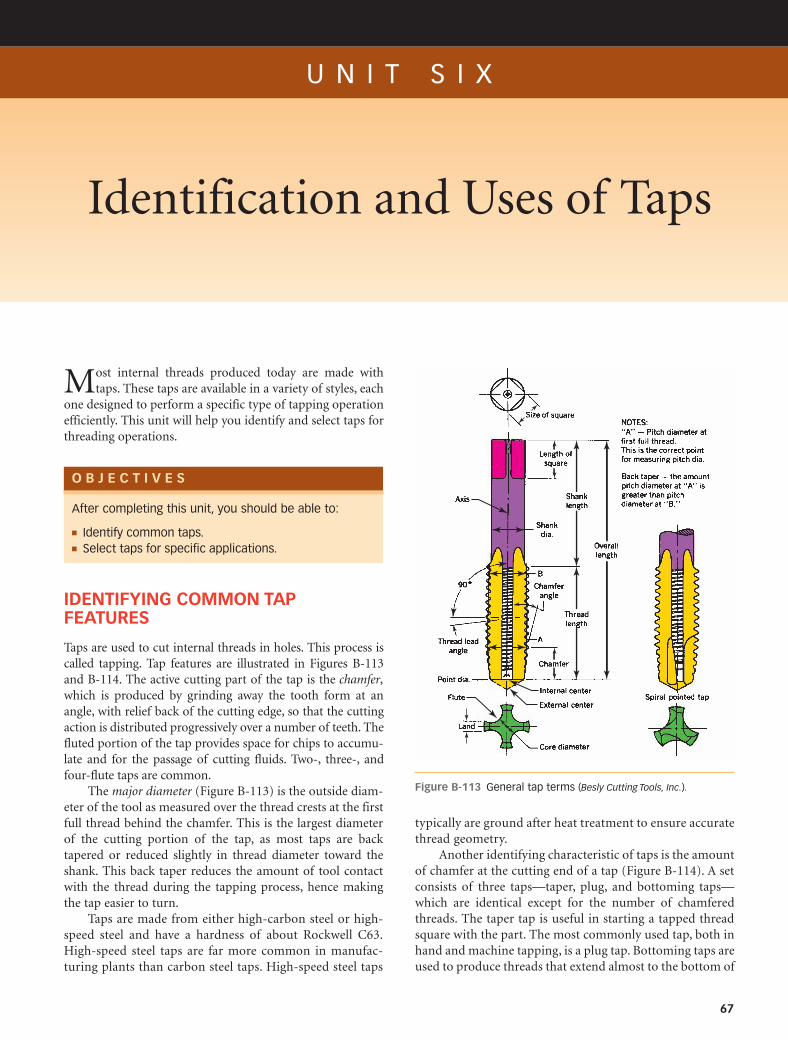
IDENTIFYING COMMON TAPFEATURES
Taps are used to cut internal threads in holes. This process iscalled tapping. Tap features are illustrated in Figures B-113and B-114. The active cutting part of the tap is the chamfer,which is produced by grinding away the tooth form at anangle, with relief back of the cutting edge, so that the cuttingaction is distributed progressively over a number of teeth. Thefluted portion of the tap provides space for chips to accumu-late and for the passage of cutting fluids. Two-, three-, andfour-flute taps are common.
The major diameter (Figure B-113) is the outside diam-eter of the tool as measured over the thread crests at the firstfull thread behind the chamfer. This is the largest diameterof the cutting portion of the tap, as most taps are backtapered or reduced slightly in thread diameter toward theshank. This back taper reduces the amount of tool contactwith the thread during the tapping process, hence makingthe tap easier to turn.
Taps are made from either high-carbon steel or high-speed steel and have a hardness of about Rockwell C63.High-speed steel taps are far more common in manufac-turing plants than carbon steel taps. High-speed steel taps
Most internal threads produced today are made withtaps. These taps are available in a variety of styles, each
one designed to perform a specific type of tapping operationefficiently. This unit will help you identify and select taps forthreading operations.
After completing this unit, you should be able to:
! Identify common taps.! Select taps for specific applications.
67
Figure B-113 General tap terms (Besly Cutting Tools, Inc.).
typically are ground after heat treatment to ensure accuratethread geometry.
Another identifying characteristic of taps is the amountof chamfer at the cutting end of a tap (Figure B-114). A setconsists of three taps—taper, plug, and bottoming taps—which are identical except for the number of chamferedthreads. The taper tap is useful in starting a tapped threadsquare with the part. The most commonly used tap, both inhand and machine tapping, is a plug tap. Bottoming taps areused to produce threads that extend almost to the bottom of
M02_KIBB5087_09_SE_C02.qxd 1/26/09 5:30 PM Page 67REVISED

68 SECTION B HAND TOOLS
Figure B-114 Chamfer designations for cutting taps. Top tobottom: starting tap, plug tap, and bottoming tap.
Figure B-115 Interrupted thread tap.
5/8"–11–NCG–H3
H5
Figure B-116 Identifying marking on a tap.
Figure B-117 Set of spiral pointed (or gun) taps.
Figure B-118 Cutting action of spiral pointed taps.
a blind hole. A blind hole is one that is not drilled entirelythrough a part.
Serial taps are also made in sets of three taps for anygiven size of tap. Each of these taps has one, two, or threerings cut on the shank near the square. The No. 1 tap hassmaller major and pitch diameters and is used for rough cut-ting the thread. The No. 2 tap cuts the thread slightly deeper,and the No. 3 tap finishes it to size. Serial taps are used whentapping tough metals by hand. Another tap used for toughmetal such as stainless steel is the interrupted thread tap(Figure B-115). This tap has alternate teeth removed toreduce tapping friction.
Figure B-116 shows the identifying markings of a tap,where in. is the nominal size, 11 is the number of threadsper inch, and NC refers to the standardized National Coarsethread series. G is the symbol used for ground taps. H3 iden-tifies the tolerance range of the tap. HS means that the tapmaterial is high-speed steel. Left-handed taps will also beidentified by an LH or left-hand marking on the shank. Moreinformation on taps may be found in Machinery’s Handbook.
OTHER KINDS AND USES OF TAPS
Spiral pointed taps (Figure B-117), often called gun taps, areespecially useful for machine tapping of through holes orblind holes with sufficient chip room below the threads.
58
When the spiral point is turned, the chips are forced aheadof the tap (Figure B-118). Since the chips are pushed aheadof the tap, the problems caused by clogged flutes, especiallybreakage of taps, are eliminated if it is a through hole. If aspiral pointed tap is used to tap a blind hole, sufficient holedepth is necessary to accommodate the chips that are pushedahead of the tap. Also, since they are not needed for chip dis-posal, the flutes of spiral pointed taps can be made shallower,thus increasing the strength of the tap.
Spiral pointed taps can be operated at higher speedsand require less torque to drive than ordinary hand taps.Figure B-119 shows the design of the cutting edges. The cut-ting edges (a) at the point of the tap are ground at an angle(b) to the axis. Fluteless spiral pointed taps (Figure B-120)are recommended for production tapping of through holesin sections no thicker than the tap diameter. This type of tapis strong and rigid, which reduces tap breakage caused bymisalignment. Fluteless spiral point taps give excellentresults when tapping soft materials or sheet metal.
Figure B-119 Detail of spiral pointed tap.
Figure B-120 Fluteless spiral pointed tap for thin materials.
M02_KIBB5087_09_SE_C02.qxd 1/26/09 5:30 PM Page 68REVISED

UNIT SIX IDENTIFICATION AND USES OF TAPS 69
Figure B-124 The thread-forming action of a fluteless thread-forming tap.
Figure B-125 Taper pipe tap.
Figure B-121 Spiral fluted taps––regular spiral.
Figure B-122 Spiral fluted tap––fast spiral. The action of the taplifts the chips out of the hole to prevent binding.
Figure B-123 Fluteless thread-forming tap.
Spiral fluted taps are made with helical flutes instead ofstraight flutes (Figure B-121), which draw the chips out of thehole. This kind of tap is also used when tapping a hole thathas a keyseat or spline, as the helical lands of the tap willbridge the interruptions. Spiral fluted taps are recommendedfor tapping deep blind holes in ductile materials such as alu-minum, magnesium, brass, copper, and die-cast metals. Fastspiral fluted taps (Figure B-122) are similar to regular spiralfluted taps, but the faster spiral flutes increase the chip liftingaction and permit the spanning of comparably wider spaces.
Thread-forming taps (Figure B-123) are fluteless anddo not cut threads in the same manner as conventional taps.They are forming tools, and their action can be comparedwith external thread rolling. On ductile materials such as alu-minum, brass, copper, die castings, lead, and leaded steels,these taps give excellent results. Thread-forming taps are held
and driven just like conventional taps, but because they donot cut the threads, no chips are produced. Problems of chipcongestion and removal often associated with the tapping ofblind holes are eliminated. Figure B-124 shows how thethread-forming tap displaces metal. The crests of the threadat the minor diameter may not be flat but will be slightly con-cave because of the flow of the displaced metal. Threads pro-duced in this manner have improved surface finish andincreased strength because of the cold working of the metal.The size of the hole to be tapped must be closely controlled,since too large a hole will result in a poor thread form, andtoo small a hole will result in the breaking of the tap.
A tapered pipe tap (Figure B-125) is used to tap holes witha taper of in. per foot for pipes with a matching thread and toproduce a leakproof fit. The nominal size of a pipe tap is thatof the pipe fitting and not the actual size of the tap. When taperpipe threads are tapped, every tooth of the tap engaged withthe work is cutting until the rotation is stopped. This takesmuch more torque than does the tapping of a straight threadin which only the chamfered end and the first full thread areactually cutting. Straight pipe taps (Figure B-126) are used fortapping holes or couplings to fit taper-threaded pipe and tosecure a tight joint when a sealer is used.
A pulley tap (Figure B-127) is used to tap set screw andoilcup holes in the hubs of pulleys. The long shank also per-mits tapping in places that might be inaccessible for regularhand taps. When used for tapping pulleys, these taps are
34
M02_KIBB5087_09_SE_C02.qxd 1/26/09 5:30 PM Page 69REVISED

70 SECTION B HAND TOOLS
Figure B-126 Straight pipe tap.
Figure B-127 Pulley tap.
Figure B-128 Nut tap.
Figure B-129 Set of Acme thread taps. The upper tap is used forroughing, the lower tap for finishing.
Figure B-130 Tandem Acme tap designed to rough and finishcut the thread in one pass.
Figure B-131 Rake and hook angles on cutting taps (Besly
Cutting Tools, Inc.).
inserted through holes in the rims, which are slightly largerthan the shanks of the taps. These holes serve to guide thetaps and assure proper alignment with the holes to betapped.
Nut taps (Figure B-128) differ from pulley taps in thattheir shank diameters are smaller than the root diameter of thethread. The smaller shank diameter makes the tapping of deepholes possible. Nut taps are used when small quantities of nutsare made or when nuts have to be made from tough materialssuch as some stainless steels or similar alloys.
Figure B-129 shows Acme taps for roughing and finish-ing. Acme threads are used to provide accurate movement—for example, in lead screws on machine tools—and forapplying pressure in various mechanisms. On some Acmetaps the roughing and finishing operation is performed withone tap (Figure B-130). The length of this tap usuallyrequires a through hole.
RAKE AND HOOK ANGLES ONCUTTING EDGES
When selecting a tap for the most efficient cutting, the cut-ting face geometry will be an important factor. It should varydepending on the material to be tapped. Cutting face geom-etry is expressed in terms of rake and hook (Figure B-131).The rake of a tap is the angle between a line through the flatcutting face and a radial line from the center of the tool tothe tooth tip. The rake can be negative, neutral, or positive.Hook angle, on the other hand, relates to the concavity of thecutting face. It is defined by the intersection of the radial linewith the tangent line through the tooth tip (tangential hook)or by the average angle of the tooth face from crest to root(chordal). Unlike the rake angle, the hook angle cannot benegative. Table B-1 gives the rake angle recommendationsfor workpiece materials. In general, the softer or more duc-tile the material, the greater the rake angle. Harder and morebrittle materials call for reduced rake angles.
REDUCING FRICTION IN TAPPING
As discussed earlier in this unit, a tap is usually back taperedalong the thread to relieve the friction between the tool and theworkpiece. Another form of relief is often applied to taps with
Table B-1 Recommended Tap Rake Angles
0–5 Degrees 8–12 Degrees 16–20 Degrees
Bakelite Bronze Aluminum and alloys
Plastics Hard rubber Zinc die castings
Cast iron Cast steel Copper
Brass Carbon steel Magnesium
Hard rubber Alloy steel
Stainless steel
M02_KIBB5087_09_SE_C02.qxd 1/26/09 5:30 PM Page 70REVISED

UNIT SIX IDENTIFICATION AND USES OF TAPS 71
Figure B-132 Pitch diameter relief forms on taps (Besly Cutting
Tools, Inc.).
Concave groove band relief
Figure B-133 Tap with concave groove land relief.
the same results. When the fully threaded portion of the tap iscylindrical (other than back taper), it is called a concentricthread (Figure B-132). If the pitch diameter of the fully threadedportion of the tap is brought uniformly closer to the axis ofthe tap as measured from face to back (heel), it has eccentricrelief. This means less tool contact with the workpiece andless friction. A third form of friction relief combines the con-centric thread and the eccentric thread relief and is termed con-eccentric. The concentric margin gives substantial guidance,and the relief following the margin reduces friction. Relief isalso provided behind the chamfer of the tap to provide radialclearance for the cutting edge. Relief may also be provided inthe form of a channel that runs lengthwise down the center ofthe land (Figure B-133), termed a concave groove land relief.
Other steps may also be taken to reduce friction and toincrease tap life. Surface treatment of taps is often an answerif poor thread forming or tap breakage is caused by chipsadhering to the flutes or welding to the cutting faces. Thesetreatments generally improve the wear life of taps by increas-ing their abrasion resistance.
Different kinds of surface treatments are used by tap man-ufacturers. Liquid nitride produces a hard, shallow surface onhigh-speed steel tools when these tools are immersed incyanide salts at closely controlled temperatures. Oxide finishesare usually applied in steam tempering furnaces and can beidentified by their bluish black color. The oxide acts as a solidlubricant. It also holds liquid lubricant at the cutting edgesduring a tapping operation. Oxide treatments prevent chipsfrom welding to the tool and reduce friction between the tooland the work. Chrome plating is an effective treatment fortaps used on nonferrous metals and some soft steels. Thechromium deposit is shallow and often referred to as flashchrome plating. Titanium nitride is another effective coating forextending the working life of taps.
SELF-TEST1. What difference exists between a set of taps and serial taps?
2. Where is a spiral pointed tap used?
3. When is a fluteless spiral pointed tap used?
4. When is a spiral fluted tap used?
5. How are thread-forming taps different from conventional taps?
6. How are taper pipe taps identified?
7. Why are finishing and roughing Acme taps used?
8. Why are the rake angles varied on taps for different materials?
9. Name at least three methods used by tap manufacturers toreduce friction between the tap and the workpiece material.
10. What is the advantage of a fluteless tap?
INTERNET REFERENCESInformation on taps
www.e-taps.com
www.osgtool.com
http://www.google.com/threadingtaps
http://www.directindustry.com
M02_KIBB5087_09_SE_C02.qxd 1/26/09 5:30 PM Page 71REVISED

U N I T S E V E N
Tapping Procedures
72
Today’s mass production of consumer goods depends toa large extent on the efficient and secure assembly of
parts using threaded fasteners. It takes skill to produceusable tapped holes, so a worker in the metal trades musthave an understanding of the factors that affect the tappingof a hole, such as the work material and its cutting speed,the proper cutting fluid, and the size and condition of thehole. A good machinist can analyze a tapping operation,determine whether it is satisfactory, and usually find a solu-tion if it is not. In this unit you will learn about commontapping procedures.
O B J E C T I V E S
After completing this unit, you should be able to:
! Select the correct tap drill for a specific percentage ofthread.
! Determine the cutting speed for a given workmaterial–tool combination.
! Select the correct cutting fluid for tapping.! Tap holes by hand or with a drill press.! Identify and correct common tapping problems.
Figure B-134 Tap wrench.
Figure B-135 T-handle tap wrench.
for tapping with a tapping attachment (Figure B-137).Some of these tapping attachments have an internal fric-tion clutch, so that downward pressure on the tap turns thetap forward and feeds it into the work. Releasing down-ward pressure will automatically reverse the tap and back itout of the workpiece. Some tapping attachments have leadscrews that provide tap feed rates equal to the lead of thetap. Most of these attachments also have an adjustment to
TAP USE
Taps are used to cut internal threads in holes. The actual cut-ting process is called tapping and can be performed by hand orwith a machine. A tap wrench (Figure B-134) or a T-handletap wrench (Figure B-135) attached to the tap is used to pro-vide driving torque while hand tapping. To obtain a greateraccuracy in hand tapping, a hand tapper (Figure B-136) isused. This fixture acts as a guide for the tap to ensure that itstays in alignment and cuts concentric threads.
Holes can also be tapped in a drill press that has a spin-dle reverse switch, which is often foot operated for conven-ience. Drill presses without reversing switches can be used
M02_KIBB5087_09_SE_C02.qxd 1/26/09 5:30 PM Page 72REVISED

UNIT SEVEN TAPPING PROCEDURES 73
limit the torque to match the size of the tap, which elimi-nates most tap breakage.
THREAD PERCENTAGE AND HOLE STRENGTH
The strength of the thread in a tapped hole depends largelyon the workpiece material, the percentage of full threaddepth used, and the length of the thread. The workpiece
material is usually selected by the designer, but themachinist can often control the percentage of thread pro-duced and the depth of the thread. The percentage ofthread produced is dependent on the diameter of thedrilled hole. Tap drill charts generally give tap drill sizes toproduce 75 percent thread. (See Appendix Tables 3 and 4for tap drill charts.)
An example will illustrate the relationships between thepercentage of thread, torque required to drive the tap, andresulting thread strength. An increase in thread depth from60 percent to 72 percent in AISI 1020 steel requires twice thetorque to drive the tap, but it increases the strength of thethread by only 5 percent. The practical limit seems to be 75percent of full thread, since a greater percentage of threaddoes not increase the strength of the threaded hole in mostmaterials.
In some difficult-to-machine materials such as titaniumalloys, high-tensile steels, and some stainless steels, 50 per-cent to 60 percent thread depth will give sufficient strengthto the tapped hole. Threaded assemblies are usually designedso that the bolt breaks before the threaded hole strips.Common practice is to have a bolt engage a tapped hole by1 to times its diameter.
DRILLING THE RIGHT HOLE SIZE
The condition of the drilled hole affects the quality of thethread produced, as an out-of-round hole leads to an out-of-round thread. Bellmouthed holes will produce bellmouththreads. When an exact hole size is needed, the hole shouldbe reamed before tapping. This is especially important forlarge-diameter taps and when fine pitch threads are used.The size of the hole to be drilled is usually obtained from tapdrill charts, which usually show a 75 percent thread depth. Ifa thread depth other than 75 percent is wanted, use the fol-lowing formula to determine the proper hole size: For theAmerican National Unified form:
= hole diameter
For example, to calculate the hole size for a 1-in. 12-threadfastener with a 70 percent thread depth:
This formula will work for any thread system.
SPEEDS FOR TAPPING
When a thread is tapped by hand with a tap wrench, speed isnot a consideration at all, but when a tapping machine orattachment is used, speed is very important. The quality ofthe thread produced also depends on the speed at which atap is operated. The selection of the best speed for tapping is
1.0 - .01266 * 70%12
= .926
.01266 * % of thread depth
number of threads per inch (TPI)Outside diameter of thread -
112Figure B-136 Hand tapper (Courtesy of Enco).
Figure B-137 Drill press tapping attachment.
M02_KIBB5087_09_SE_C02.qxd 1/26/09 5:30 PM Page 73REVISED

Figure B-138 Tap extractor.
C A U T I O N
Always stand aside when cleaning out holes with com-pressed air, as chips and particles tend to fly out at highvelocity.
74 SECTION B HAND TOOLS
limited, unlike the varying speeds and feeds possible withother cutting tools, because the feed per revolution is fixedby the lead of the thread. Excessive speed develops high tem-peratures that cause rapid wear of the tap’s cutting edge.Dull taps produce rough or torn and off-size threads. Highcutting speeds prevent adequate lubrication at the cuttingedges and often create a problem of chip disposal.
When selecting the best speed for tapping, you shouldconsider not only the material being tapped, but also the sizeof the hole, the kind of tap holder being used, and the lubri-cant being used. Table B-2 gives guidelines in selecting aspeed and a lubricant for materials when using high-speedsteel taps.
These cutting speeds in feet per minute have to be trans-lated into rpm to be useful. For example, calculate the rpmwhen tapping a -24 UNF hole in free-machining steel. Thecutting speed chart gives a cutting speed between 60 and 80ft/min. Use the lower figure; you can increase the speed onceyou see how the material taps. The formula for calculatingrpm is
Lubrication is one of the most important factors in atapping operation. Cutting fluids used when tapping serve ascoolants but are more important as lubricants. It is impor-tant to select the correct lubricant because using the wronglubricant may give results that are worse than if no lubricantwere used. For lubricants to be effective, they should beapplied in sufficient quantity to the actual cutting area in thehole. (See Section F for more information on cutting speedsand cutting fluids.)
cutting speed 1CS2 * 4
diameter 1D2 or 60 * 4
3>8 = 640 rpm
38
Table B-2 Recommended Cutting Speeds andLubricants for Machine Tapping
Material Speeds (ft/min) Lubricant
Aluminum 90–100 Kerosene and light base oil
Brass 90–100 Soluble oil or light base oil
Cast iron 70–80 Dry or soluble oil
Magnesium 20–50 Light base oil diluted with kerosene
Phosphor bronze 30–60 Mineral oil or light base oil
Plastics 50–70 Dry or air jet
Steels
Low carbon 40–60 Sulfur-base oilHigh carbon 25–35 Sulfur-base oilFree machining 60–80 Soluble oilMolybdenum 10–35 Sulfur-base oilStainless 10–35 Sulfur-base oil
SOLVING TAP PROBLEMS
In Table B-3, common tapping problems are presented withsome possible solutions. Occasionally, it becomes necessaryto remove a broken tap from a hole. If a part of the brokentap extends out of the workpiece, removal is relatively easywith a pair of pliers. If the tap breaks flush with or below thesurface of the workpiece, a tap extractor can be used (FigureB-138). Before trying to remove a broken tap, remove thechips in the flutes. A jet of compressed air or cutting fluidcan be used for this.
When the chips are packed so tightly in the flutes or thetap is jammed in the work so that a tap extractor cannot beused, the tap may be broken up with a pin punch andremoved piece by piece. If the tap is made from carbon steeland cannot be pin punched, the tap can be annealed so itbecomes possible to drill it out.
On high-speed steel taps it may be necessary to use anelectrical discharge machine (EDM), sometimes called a tap disintegrator, to remove the broken tap. These machineserode away material from extremely hard workpieces whilethey are immersed in a fluid. The shape of the hole conformsprecisely to that of the electrode.
TAPPING PROCEDURE, HAND TAPPING
Step 1 Determine the size of the thread to be tapped andselect the tap.
Step 2 Select the proper tap drill with the aid of a tap drillchart. Choose a taper tap for hand tapping; or if a drill pressor tapping machine is to be used for alignment, use a plug tap.
Step 3 Fasten the workpiece securely in a drill press vise.Calculate the correct rpm for the drill used:
rpm = CS * 4D
M02_KIBB5087_09_SE_C02.qxd 1/26/09 5:30 PM Page 74REVISED

UNIT SEVEN TAPPING PROCEDURES 75
Step 6 Tighten the tap in the tap wrench.
Step 7 Cup your hand over the center of the wrench(Figure B-140) and place the tap in the hole in a verticalposition. Start the tap by turning two or three turns in aclockwise direction for a right-hand thread. At the sametime, keep a steady pressure downward on the tap. When thetap is started, it may be turned as shown in Figure B-141.
Countersink totap diameter
or slightly larger
Figure B-139 Preparing the workpiece. Figure B-140 Starting the tap.
Table B-3 Common Tapping Problems and Possible Solutions
Causes of Tap Breakage Solution
Tap hitting bottom of hole or bottoming on packed chips
Drill hole deeper. Eject chips with air pressure. (Caution: Stand aside when you do this and always wear safetyglasses.) Use spiral fluted taps to pull chips out of hole. Use a thread-forming tap.
Chips are packing in flutes Use a tap style with more flute space. Tap to a lesser depth or use a smaller percentage of threads. Select a tapthat will eject chips forward (spiral point) or backward (spiral fluted).
Hard materials or hard spots Anneal the workpiece. Reduce cutting speed. Use longer chamfers on tap. Use taps with more flutes.
Inadequate lubricant Use the correct lubricant and apply a sufficient amount of it under pressure at the cutting zone.
Tapping too fast Reduce cutting speed.
Excessive wearAbrasive materials Improve lubrication. Use surface-treated taps. Check the alignment of tap and hole to be tapped.
Chips clogging flutesInsufficient lubrication Use a better lubricant and apply it with pressure at the cutting zone.Excessive speed Reduce cutting speed.Wrong-style tap Use a more-free-cutting tap such as a spiral pointed tap, spiral fluted tap, interrupted thread tap, or
surface-treated taps.
Torn or rough threadsDull tap Resharpen.Chip congestion Use a tap with more chip room. Use lesser percentage of thread. Drill a deeper hole. Use a tap that will eject chips.Inadequate lubrication and chips
clogging flutesCorrect as suggested previously.
Hole improperly prepared Torn areas on the surface of the drilled, bored, or cast hole will be shown in the minor diameter of the tapped thread.
Undersize threadsPitch diameter of tap too small Use a tap with a large pitch diameter.Excessive speed Reduce tapping speed.Thin-wall material Use a tap that cuts as freely as possible. Improve lubrication. Hold the workpiece so that it cannot expand while it
is being tapped. Use an oversize tap.Dull tap Resharpen.
Oversize or bellmouth threadsLoose spindle or worn holder Replace or repair spindle or holder.Misalignment Align spindle, fixture, and work.Tap oversized Use a smaller-pitch-diameter tap.Dull tap Resharpen.Chips packed in flutes Use a tap with deeper flutes, spiral flutes, or spiral points.Buildup on cutting edges of tap Use correct lubricant and tapping speed.
Drill the hole using the recommended coolant. Check thehole size.
Step 4 Countersink the hole entrance to a diameter slightlylarger than the major diameter of the threads (Figure B-139).This allows the tap to be started more easily, and it protectsthe start of the threads from damage.
Step 5 Mount the workpiece in a bench vise so that thehole is in a vertical position.
M02_KIBB5087_09_SE_C02.qxd 1/26/09 5:30 PM Page 75REVISED

76 SECTION B HAND TOOLS
Step 9 Use the correct cutting oil on the tap when cuttingthreads.
Step 10 Turn the tap clockwise one-quarter to one-halfturn and then turn it back three-quarters of a turn to breakthe chip. Do this with a steady motion to avoid breaking the tap.
Step 11 When tapping a blind hole, use the taps in theorder starting, plug, and then bottoming. Remove the chipsfrom the hole before using the bottoming tap, and be carefulnot to hit the bottom of the hole with the tap.
Step 12 Figure B-143 shows a 60-degree point centerchucked in a drill press to align a tap squarely with the previ-ously drilled hole. Only very slight follow-up pressureshould be applied to the tap. Too much downward pressurewill cut a loose, oversize thread.Figure B-141 Tapping a thread by hand.
Figure B-142 Checking the tap for squareness.
Figure B-143 Using the drill press as a tapping fixture.
SELF-TEST1. What kind of tools are used to drive taps when hand tapping?
2. What is a hand tapper?
3. What is a tapping attachment?
4. Which three factors affect the strength of a tapped hole?
5. How deep should the usable threads be in a tapped hole?
6. When should tap drill holes be reamed?
7. What causes taps to break while tapping?
8. What causes rough and torn threads?
9. What causes oversized threads in a hole?
10. Give three methods of removing broken taps from holes.
Step 8 After the tap is started for several turns, remove thetap wrench without disturbing the tap. Place the blade of asquare against the solid shank of the tap to check for square-ness (Figure B-142). Check from two positions 90 degreesapart. If the tap is not square with the work, it will ruin thethread and possibly break in the hole if you continue tap-ping. Back the tap out of the hole and restart.
M02_KIBB5087_09_SE_C02.qxd 1/26/09 5:30 PM Page 76REVISED

77
U N I T E I G H T
Thread-Cutting Dies and Their Uses
fit on a threaded part. Adjustments made to obtain threadsseveral thousandths of an inch oversize will result in poor dieperformance, because the heel of the cutting edge will drag onthe threads. Excessive expansion may cause the die to break.
Some round split adjustable dies do not have the built-in adjusting screw. Adjustments are then made with thethree screws in the diestock (Figure B-145). Two of thesescrews on opposite sides of the diestock hold the die in thediestock and also provide closing pressure. The third screwengages the split in the die and provides opening pressure.These dies are used in a diestock for hand threading or in amachine holder for machine threading.
Another type of threading die is the two-piece die,whose halves (Figure B-146) are called blanks. The blanks areassembled in a collet consisting of a cap and the guide (FigureB-147). The normal position of the blanks in the collet isindicated by witness marks (Figure B-148). The adjusting
O B J E C T I V E S
A die is used to cut external threads on the surface of abolt or rod. Many machine parts and mechanical assem-
blies are held together with threaded fasteners, most ofwhich are mass-produced. If necessary, the threaded portionof a bolt may be extended with a die toward the head, butthis should be done with unhardened bolts, as cutting heat-treated bolts will dull the die. In this unit you will be intro-duced to some thread-cutting dies and their uses.
After completing this unit, you should be able to:
! Identify dies used for hand threading.! Select and prepare a rod for threading.! Cut threads with a die.
Figure B-144 Markings on a die. (Example shown is a roundsplit adjustable die.)
Dies are used to cut external threads on round materi-als. Some dies are made from carbon steel, but most aremade from high-speed steel. Dies are identified by the mark-ings on the face as to the size of thread, number of threadsper inch, and form of thread, such as NC, UNF, or otherstandard designations (Figure B-144).
COMMON TYPES OF HANDTHREADING DIES
The die shown in Figure B-144 is an example of a round splitadjustable die, also called a button die. These dies are madein all standardized thread sizes up to thread diameters and pipe threads. The outside diameters of these diesvary from to 3 in.
Adjustments on these dies are made by turning a fine-pitch screw that forces the sides of the die apart or allows themto spring together. The range of adjustment of round splitadjustable dies is very small, allowing only for a loose or tight
58
12 - in .
112 -
in .
M02_KIBB5087_09_SE_C02.qxd 1/26/09 5:30 PM Page 77REVISED

78 SECTION B HAND TOOLS
Figure B-145 Diestock for round split adjustable dies.
Figure B-146 Die halves for two-piece die.
! "
Figure B-147 Components of a split adjustable die collet.
screws allow for precise control of the cut thread size. Theblanks are inserted in the cap with the tapered threadstoward the guide. Each of the two die halves is stamped witha serial number. Make sure that the halves you select have thesame numbers. The guide used in the collet serves as an aidin starting and holding the dies square with the work beingthreaded. Each thread size uses a guide of the same nominalor indicated size. Collets are held securely in diestocks(Figure B-149) by a knurled setscrew that seats in a dimplein the cap.
Hexagon rethreading dies (Figure B-150) are used torecut slightly damaged or rusty threads. Rethreading diesare driven with a wrench large enough to fit the die. Solidsquare dies (Figure B-151) have the same uses as hexagonrethreading dies. All the die types discussed previously arealso available in pipe thread sizes. Square dies are used tocut new threads and have sufficient chip clearance for thispurpose.
Adjustingscrew
Adjusting screw
Width of blankand cap slot
Blank(end view)
Witnessmark
Witnessmark
Figure B-148 Setting the die position to the witness marks onthe die and collet assembly.
Figure B-149 Diestock for adjustable die and collet assembly.
Figure B-150 Hexagon rethreading die.
M02_KIBB5087_09_SE_C02.qxd 1/26/09 5:30 PM Page 78REVISED

UNIT EIGHT THREAD-CUTTING DIES AND THEIR USES 79
HAND THREADING PROCEDURES
Threading of a rod should always be started with the leadingor throat side of the die. This side is identified by the cham-fer on the first two or three threads and also by the sizemarkings. The chamfer distributes the cutting load over anumber of threads, which produces better threads and lesschance of chipping the cutting edges of the die. Cutting oilor other threading fluids are important in obtaining qualitythreads and maintaining long die life. Once a cut is startedwith a die, it will tend to follow its own lead, but unevenpressure on the die stock will make the die cut variable helixangles or “drunken” threads.
Threads cut by hand often show a considerable accumu-lated lead error. The lead of a screw thread is the distance anut will move on the screw if it is turned one full revolution.This problem results because the dies are relatively thincompared with the diameter of thread they cut. Only a fewthreads in the die can act as a guide on the already cutthreads. This error usually does not cause problems whenstandard or thin nuts are used on the threaded part.However, when an item with a long internal thread is assem-bled with a threaded rod, it usually tightens and then locks,not because the thread depth is insufficient, but becausethere is a lead error. This lead error can be as much as one-fourth of a thread in 1 in. of length.
The outside diameter of the material to be threadedshould not be more than the nominal size of the thread andpreferably a few thousandths of an inch (.002 to .005 in.)undersized. After a few full threads are cut, the die should beremoved so that the thread can be tested with a nut or threadring gage. A thread ring gage set usually consists of twogages, a go and a no go gage. As the names imply, a go gageshould screw on the thread, whereas the no go gage will notgo more than turns on a thread of the correct size. Do notassume that the die will cut the correct size thread; alwayscheck by gaging or assembling. Adjustable dies should bespread open for the first cut and set progressively smaller foreach pass after checking the thread size.
112
It is important that a die be started squarely on the rodto be threaded. A lathe can be used as a fixture for cuttingthreads with a die (Figure B-152). The rod is fastened in alathe chuck for rotation, while the die is held square becauseit is supported by the face of the tailstock spindle. The car-riage or the compound rest prevents the diestock from turn-ing while the chuck is rotated by hand. As the die advances,the tailstock spindle is also advanced to stay in contact withthe die. Do not force the die with the tailstock spindle, or aloose thread may result. A die may be used to finish to size along thread that has been rough threaded on the lathe.
It is always good practice to chamfer the end of a work-piece before starting a die (Figure B-153). The chamfer on theend of a rod can be made by grinding on a pedestal grinder,by filing, or with a lathe. This will help in starting the cut andwill also leave a finished thread end. When cutting threads
Figure B-151 Solid square die.
Figure B-152 Threading a rod with a hand die in a lathe.
45ºApproximately 1/2 the
pitch of the threadto be cut
Figure B-153 Chamfer workpiece before using die.
M02_KIBB5087_09_SE_C02.qxd 1/26/09 5:30 PM Page 79REVISED

with a hand die, reverse the rotation of the die after each fullturn forward to break the chips into short pieces that will fallout of the die. Chips jammed in the clearance holes will tearthe thread.
THREADING PROCEDURE,THREADING DIES
Step 1 Select the workpiece to be threaded and measure itsdiameter. Then, chamfer the end, either on a grinder or witha file. The chamfer should be at least as deep as the thread tobe cut.
Step 2 Select the correct die and mount it in a diestock.
Step 3 Mount the workpiece in a bench vise. Short work-pieces are mounted vertically and long pieces usually areheld horizontally.
Step 4 To start the thread, place the die over the work-piece. Holding the diestock with one hand (Figure B-154),apply downward pressure and turn the die.
Step 5 When the cut has started, apply cutting fluid to theworkpiece and die, and start turning the diestock with bothhands (Figure B-155). After each complete revolution for-ward, reverse the die one-half turn to break the chips.
Step 6 Check to see that the thread is started square, usinga machinist’s square. Make any necessary corrections byapplying slight downward pressure on the high side whileturning.
SELF-TEST1. What is a die?
2. What tool is used to drive a die?
3. How much adjustment is possible with a round splitadjustable die?
4. What is the purpose of the guide in a two-piece adjustabledie collet?
5. What are important points to watch when assembling two-piece dies in a collet?
6. Where are hexagon rethreading dies used?
7. Why do dies have a chamfer on the cutting end?
8. Why are cutting fluids used?
9. What diameter should a rod be before being threaded?
10. Why should a rod be chamfered before being threaded?
INTERNET REFERENCESInformation on threading dies
http://www.tapsdiesandreamers.com
http://en.wikipedia.org/Wiki/Taps_and_diesFigure B-154 Start the die with one hand.
Figure B-155 Use both hands to turn the threading die.
Step 7 When several turns of the thread have been com-pleted, check the fit of the thread with a nut, thread ringgage, thread micrometer, or the mating part. If the thread fitis incorrect, adjust the die with the adjustment screws andtake another cut with the adjusted die. Continue makingadjustments until the proper fit is achieved.
Step 8 Continue threading to the required thread length.To cut threads close to a shoulder, invert the die after thenormal threading operation and cut the last two or threethreads with the side of the die that has less chamfer.
80 SECTION B HAND TOOLS
M02_KIBB5087_09_SE_C02.qxd 1/26/09 5:30 PM Page 80REVISED

81
U N I T N I N E
Off-Hand Grinding
Setup of the Pedestal GrinderThe pedestal grinder in your shop stands ready for use mostof the time. If it becomes necessary to replace a worn wheel,the side of the guard must be removed and the tool restmoved out of the way. A piece of wood may be used to pre-vent the wheel from rotating so that the spindle nut can beturned and removed (Figure B-156). Remember that the leftside of the spindle has left-handed threads, and the right sidehas right-handed threads.
A new wheel should be ring tested to determine whetherthere are any cracks or imperfections (Figure B-157). Gentlytap the wheel near its rim with a screwdriver handle or apiece of wood and listen for a clear ringing sound like that ofa bell. A clear ring indicates a sound wheel that is safe to use;if a dull thud is heard, the wheel may be cracked and shouldnot be used. Check that the flanges and the spindle are cleanbefore mounting the wheel. Be sure that the center hole inthe wheel is the correct size for the grinder spindle. If youmust use a bushing, be sure that it is the correct size andinstalled properly (Figure B-158). Place a clean, undamaged
O B J E C T I V E
Although it is a machine tool, the pedestal grinder is usedfor many hand grinding operations, especially sharpen-
ing and shaping drills and tool bits. In this unit you will studythe setup, use, and safety aspects of this important machine.
After completing this unit, you should be able to:
! Describe the setup, use, and safety of the pedestalgrinder.
Figure B-156 Using a piece of wood to hold the wheel whileremoving the spindle nut.
OFF-HAND GRINDING ON PEDESTAL GRINDERS
The pedestal grinder is really a machine tool. However, sincethe workpiece is handheld, it is more logical to discuss thismachine in conjunction with hand tools. Furthermore, youmust be familiar with the pedestal grinder, as you will beusing it early in your study of machine tool practices.
The pedestal grinder gets its name from the floor standor pedestal that supports the motor and abrasive wheels. Thepedestal grinder is a common machine tool that you will usealmost daily in the machine shop. This grinding machine isused for general-purpose, off-hand grinding in which theworkpiece is handheld and applied to the rapidly rotatingabrasive wheel. One of the primary functions of the pedestalgrinder is shaping and sharpening tool bits and drills inmachine shop work. Pedestal grinders are often modified foruse with rotary wire brushes or buffing wheels.
Large, heavy-duty pedestal grinders are sometimes foundin machine shops. These grinders are used for rough grinding(snagging) welds, castings, and general rough work. Thesemachines are generally set up in a separate location from thetool grinders. Rough grinding of metal parts should never bedone on tool grinders because it causes the wheels to becomerounded, grooved, uneven, and out-of-round. In that condi-tion they are useless for tool grinding.
M02_KIBB5087_09_SE_C02.qxd 1/26/09 5:30 PM Page 81REVISED

82 SECTION B HAND TOOLS
Figure B-157 The ring test is made before mounting the wheel.
Figure B-158 The wheel is mounted with the proper bushing inplace.
Figure B-159 The tool rest is adjusted.
blotter on each side between wheel and flanges. Tighten thespindle nut just enough to hold the wheel firmly. Excessivetightening will break the wheel.
After you have replaced the guard and cover plate, bringthe tool rest up to the wheel so that there is -to clear-ance between the rest and wheel (Figure B-159). If there is
18 - in .1
16
excessive space between the tool rest and the wheel, a smallworkpiece, such as a tool bit that is being ground, may flipup and catch between the wheel and tool rest.
Figure B-160 The spark guard is adjusted.
C A U T I O N
Your finger may be caught between the workpiece andthe grinding wheel, resulting in a serious injury, if thetool rest is not adjusted properly.
The clearance between the tool rest and wheel shouldnever exceed in. The spark guard, located on the upper sideof the wheel guard (Figure B-160), should be adjusted towithin in. of the wheel. This protects the operator if thewheel should shatter.
Dressing the Grinding WheelStand aside out of the line of the rotation of the grindingwheel and turn on the grinder. Let the wheel run idle for a fullminute. A new wheel does not always run exactly true andtherefore must be dressed. A Desmond dresser (Figure B-161)may be used to sharpen and to some extent true the face ofthe wheel. Pedestal grinder wheels often become grooved,out-of-round, glazed, or misshapen and therefore must befrequently dressed to obtain proper grinding results.
The grinding wheel dresser should be used so that thenotch on the lower side is hooked behind the work rest.However, the dresser is often used in the manner shown inFigure B-161. When the tool rest extends along the side ofthe wheel, it is impossible to use the dresser properly.
Using the Pedestal GrinderBring the workpiece into contact with the wheel gently, with-out bumping. Grind only on the face of the wheel. The work-piece will heat from friction during the grinding operation.It may become too hot to hold in just a few seconds. To prevent
116
18
M02_KIBB5087_09_SE_C02.qxd 1/26/09 5:30 PM Page 82REVISED

UNIT NINE OFF-HAND GRINDING 83
(a) (b) (c) (d)
Figure B-162 The proper shape of the end of a screwdriverblade. Blades (a) and (b) are badly worn; blades (c) and (d) areground correctly.
Figure B-161 The wheel is being dressed.
this, frequently cool the workpiece in the water pot attached tothe grinder. Be especially careful when grinding drills and toolbits so that they do not become overheated. Excessive heat maypermanently affect tool steel metallurgical properties.
Screwdrivers are probably the most misused of all tools,so they are often twisted or misshapen so much that they willno longer fit a screw slot or will damage the slot if they areused (Figure B-162). Screwdrivers can be ground flat on Figure B-163 A screwdriver being hollow ground on the
periphery of the wheel.
Figure B-164 The end of the blade being squared on the wheel.
their sides, but a better method is to hollow grind them on apedestal grinder (Figure B-163). The end of the tool shouldthen be squared (Figure B-164) and given the proper thick-ness to fit the screw slot.
Center punches should also be hollow ground (FigureB-165) when they are sharpened. They should be evenlyrotated while the point is ground to the correct angle. Flatcold chisels should also be hollow ground (Figure B-166)when they are sharpened.
Layout tools, such as spring dividers and scribers,should be kept sharp by honing on a fine, flat stone in thesame way a knife is sharpened. However, when it becomesnecessary to reshape a layout tool, exercise extreme care toavoid overheating the thin point. A fine-grit wheel should beused for sharpening most cutting tools, and they should becooled frequently in water. Woodcutting tools are almostalways made of plain carbon steel, which loses its hardnesswhen overheated on the grinder. If one of these toolsbecomes blue-colored from the heat of grinding, it hasbecome too soft for cutting purposes and must either becarefully ground back past the softened edge or rehardenedand tempered.
M02_KIBB5087_09_SE_C02.qxd 1/26/09 5:30 PM Page 83REVISED

84 SECTION B HAND TOOLS
Figure B-165 This punch is being correctly sharpened toproduce a 90-degree angle for use as a center punch. It must berotated while being ground. A sharper angle of 60 degrees maybe ground to produce a prick punch.
Figure B-166 Flat chisel being ground to produce a 60-degreeangle.
Figure B-167 The force and speed of this action was such thatthe operator’s head was jerked suddenly into the guard. Note thatthe cast aluminum guard was shattered as a result of the impact.
Safety Checkpoints on the Pedestal GrinderNonferrous metals such as aluminum and brass shouldnever be ground on the aluminum oxide wheels found onmost pedestal grinders. These metals fill the voids orspaces between the abrasive particles in the grinding wheelso that more pressure is needed to accomplish the desiredgrinding. This additional pressure sometimes causes thewheel to break or shatter. Pieces of grinding wheel may bethrown out of the machine at extreme velocities. Alwaysuse silicon carbide abrasive wheels for grinding nonfer-rous metals. Excessive pressure should never be used inany grinding operation. If this seems to be necessary, itmeans that the improper grit or grade of abrasive is beingused, or the wheel is glazed and needs to be dressed.Always use the correct abrasive grit and grade for the par-ticular grinding that you are doing. (For grinding wheelselection see Section L.)
C A U T I O N
Always wear appropriate eye protection when dress-ing wheels or grinding on the pedestal grinder. Be surethat grinding wheels are rated at the proper speed forthe grinder you are using. The safety shields, wheelguards, and spark guard must be kept in place at alltimes while grinding. The tool rest must be adjustedand the setting corrected as the diameter of the wheeldecreases from use. Grinding wheels and rotary wirebrushes may catch loose clothing or long hair (FigureB-167). Long hair should be contained in an industrial-type hairnet. Wire wheels often throw out small piecesof wire at high velocities.
SELF-TEST1. What is the primary function of the pedestal grinder in a
machine shop?
2. Why should a tool grinder never be used for rough grindingmetal?
M02_KIBB5087_09_SE_C02.qxd 1/26/09 5:30 PM Page 84REVISED

UNIT NINE OFF-HAND GRINDING 85
3. When a wheel needs to be reshaped, sharpened, and tosome extent trued, what tool is usually used on a pedestalgrinder?
4. When sharpening layout tools and reshaping screwdrivers,what is the most important concern?
5. Name at least three safety factors to remember when usingthe pedestal grinder.
6. How far from the wheel should the work rest be placed?
7. Why do you allow the grinder to run a bit just after changinga wheel?
8. What is the purpose of the wheel blotter?
9. What is the primary safety consideration when selecting agrinding wheel?
10. What does the wheel ring test do?
INTERNET REFERENCESInformation on off-hand grinding process and equipment
http://www.shef.ac.uk/safety
http://books.google.com
M02_KIBB5087_09_SE_C02.qxd 1/26/09 5:30 PM Page 85REVISED