m-series climate changer™ air handlers - · pdf filelaboratory testing and numerous...
TRANSCRIPT

Applied Central-Station Air Handlers
December 2005 CLCH-PRC003-EN
M-Series Climate Changer™ Air HandlersUnit Sizes 3 to 120

2 CLCH-PRC003-EN
Feature Highlights
Table 1. Summary of Features and BenefitsFeature BenefitFlexible design • Eases retrofit, renovation, and replacement
• Allows stacked units to reduce footprint
• Allows a wide variety of fans and coils
• Optimizes coil and fan performance
• Allows pre-engineered modules to be used in custom applications
• Enables flexible module arrangementEngineered construction and casing • Provides sturdy unit construction for high performance and long life
• Provides strength to stack units with post-and-panel construction
• Enables flexible maintenance access to the unit interiorIAQ-ready unit • Meets ASHRAE Standard 62.1 requirements
• Lowers installation, startup, and operating costs
• Controls ventilation airflow directly
• Removes airborne contaminants
• Inhibits microbial growthTurnkey control options • Enables single-source responsibility
• Reduces control-system installation costs
• Ensures reliable operation
• Provides industry-standard open protocol communicationAcoustics solutions • Allows the unit to meet required NC (noise criteria) levels
• Minimizes sound source to reduce system first cost
• Provides accurate, ARI Standard 260-tested sound dataEnergy-efficient solutions • Recovers energy from the exhaust air stream
• Enables downsizing of the air-handling unit and other system components
• Reduces energy consumption of system components
• Increases operating efficiency with the low-flow, low-temperature EarthWise™ system
The M-Series Climate Changer™ air handler is a highly flexible, customizable, cataloged air handler that can meet most commercial, industrial and institutional applications. With its modular, “building-block” construction, the M-Series air handler can be tailored to meet specific job requirements for new or existing buildings. A wide range of standard and custom-engineered modules can be arranged and stacked in any number of configurations to address application and space requirements.
The wide array of available components is key to fine-tuning the performance of the M-Series air handler. The broad spectrum of fan,
coil, filter and control options allows you to optimize the performance and efficiency of your air handler.
While several air-handling manufacturers offer some custom features, most find it difficult to incorporate those features into their standard cataloged unit, which leads to increased costs and extended lead times. Trane has engineered many custom solutions - with tested performance data - for the M-Series air handler, without the cost and lead times associated with full-blown custom units.
Trane continues to develop new options for M-Series air handlers, so that you remain firmly in control of performance and cost on every design project.
© 2005 American Standard Inc. All rights reserved

CLCH-PRC003-EN 3
Contents
Feature Highlights .............................................................. 2
Features and Benefits ......................................................... 6Customizable Cataloged Air Handlers ................................................. 6Construction and Casing Integrity ....................................................... 8IAQ Air Handlers ................................................................................10Turnkey Control Options .....................................................................11Acoustic Solutions ............................................................................. 13Energy-Efficient Performance ............................................................ 14Agency Listings ................................................................................. 16
Design Application Considerations ................................. 17HVAC Design Fundamentals ..............................................................17Typical Application Considerations .................................................... 23AHU Arrangements for Specific Applications ................................... 26
M-Series Modules and Application Considerations ...... 33Access/Blank and Turning Module .................................................... 33Blender Module ................................................................................ 33Coils .................................................................................................. 34Air-to-Air, Fixed-Plate Heat Exchanger ............................................... 36Diffuser ............................................................................................. 37Discharge Plenum ............................................................................. 37Electric Heat ...................................................................................... 37Energy Wheel .................................................................................... 37Face-and-Bypass Dampers ................................................................ 38Fans ................................................................................................... 40Filters ................................................................................................ 42Gas Heat ........................................................................................... 43Humidifier ......................................................................................... 43Intake ................................................................................................ 43Mixing Box and Economizer .............................................................. 44Moisture Eliminator ........................................................................... 44Multizone .......................................................................................... 44
Quick Select ...................................................................... 45Selection Procedure .......................................................................... 45
General Data ...................................................................... 53Unit Size 3 ......................................................................................... 54Unit Size 6 ......................................................................................... 56Unit Size 8 ......................................................................................... 58Unit Size 10 ....................................................................................... 60Unit Size 12 ....................................................................................... 62

4 CLCH-PRC003-EN
Contents
Unit Size 14 ....................................................................................... 64Unit Size 17 ....................................................................................... 66Unit Size 21 ....................................................................................... 68Unit Size 25 ....................................................................................... 70Unit Size 30 ....................................................................................... 72Unit Size 35 ........................................................................................74Unit Size 40.........................................................................................76Unit Size 50 ....................................................................................... 78Unit Size 57 ....................................................................................... 80Unit Size 66 ....................................................................................... 82Unit Size 80 ....................................................................................... 84Unit Size 100 ..................................................................................... 86Unit Size 120 ..................................................................................... 88
Coil Data ............................................................................ 90Coil Circuiting .................................................................................... 94Face-Velocity Limits for Moisture Carryover ....................................101
Module Performance Data ..............................................109Accessories ......................................................................................109Blender Module ...............................................................................109Dampers .......................................................................................... 110Mixing Box with Dampers ................................................................116Damper Torque Requirements .........................................................118Discharge Plenums ..........................................................................119Filters .............................................................................................. 122Fans ................................................................................................. 123Gas Heat ......................................................................................... 123Silencers ......................................................................................... 123
Dimensional Data by Module ........................................ 124Access Module ............................................................................... 124Blender Module .............................................................................. 126Unit Mounting ................................................................................. 127Coils ................................................................................................ 128Bypass Dampers ............................................................................. 136Diffuser ........................................................................................... 139Discharge Plenum ........................................................................... 140Electric Heat .................................................................................... 143Energy Wheel .................................................................................. 144Fans................................................................................................. 148Filters .............................................................................................. 160Filter Placement ...............................................................................172Humidifier ........................................................................................ 176
CLCH-PRC003-EN 5
Contents
Intake Module ..................................................................................177Mixing Box ....................................................................................... 178Moisture Eliminator ......................................................................... 184Multizone ........................................................................................ 186Silencer ........................................................................................... 190
Electrical Data ................................................................. 191
Installation Considerations ............................................ 193Preparing the Unit Site .................................................................... 193External Support Kit Weight ............................................................ 194
Mechanical Specifications ............................................. 196Unit Construction ............................................................................ 196External Support Kit (Optional) ........................................................ 196Fans ................................................................................................. 197Coils ................................................................................................ 198Filters .............................................................................................. 199Mixing and Bypass .......................................................................... 200Other Modules and Options ............................................................201Controls ............................................................................................201
Literature References ...................................................... 204

6 CLCH-PRC003-EN
Features and Benefits
Customizable Cataloged Air HandlersFlexibility and versatility are standard in the M-Series air handler. As a customizable cataloged air handler, standard components can be arranged to meet most commercial, institutional and industrial applications for the indoor air handler market. Pre-engineered custom options expand that flexibility while ensuring proven, tested performance and dependability, and reducing the costs and long lead times associated with most custom units. Some projects call for an air handler that incorporates new, emerging technologies or a job-specific requirement. Trane’s experienced team of professionals can tailor the M-Series air handler to meet these requirements. These factory-packaged specials deliver Trane quality, enable simplified on-site installation and startup.
Figure 1. The M-Series air handler post-and panel construction makes it easy to stack modules-even coil modules.
Flexible Design
The M-Series air handler design adopts a “building-block” approach that allows you to design a unit specifically for your project. Choose the “blocks” you need from the wide range of standard and custom-engineered modules available, and arrange them to satisfy the air-handling requirements of the application.
Reduces Footprint when Stacked
The M-Series unit’s post-and-panel construction design makes it easy to stack modules - even coil modules. Reducing the unit footprint is very advantageous, especially in tight mechanical rooms. The structural integrity remains intact, even when the panels are removed (see Figure 1).
Eases Retrofit, Renovation, and
Replacement
Buildings age, usage changes, loads change, new technology emerges, codes and standards are revised. Change is inevitable.
The M-Series air handler - with its modular components, bolted construction, and removable panels - readily lends itself to the special needs of the renovation, retrofit, and replacement markets. To integrate new features, simply separate the existing modules and add, enhance, or replace components.
The M-Series air handler can be shipped in small segments (see Figure 2) that can easily be moved into tight spaces of existing buildings.
Component Flexibility
Offers a Wide Variety of Fans
An extensive array of fan types and options, including variable-frequency drives for modulation in variable-air-volume systems, further enhance the flexibility of the M-Series air handler. You choose the fan that best satisfies your supply and exhaust or return fan needs. The wide variety of fans and options lets you optimize the fan in the unit to best fit not only the airflow and static pressure requirements, but also the acoustical, efficiency, and discharge requirements.
Figure 2. Building-block design eases retrofit, allowing segments to fit into tight spaces, such as elevators.

Features and Benefits
CLCH-PRC003-EN 7
Figure 3. Typical airfoil (AF) fan
Figure 4. Typical airfoil vaneaxial (Q) fan
Fan types include:
• Double-width/double-inlet (DWDI) centrifugal fans with front, top, or bottom discharges in the following available types:
– Forward-curved (FC)
– Backward-curved (BC)
– Airfoil (AF)
• Single-width/single-inlet (SWSI) plenum fans (commonly called plug fans) with multiple or single discharges on the front, top, bottom, or sides of the module
• Airfoil vaneaxial fans (Model Q™ fan) with horizontal discharge for unit sizes 12 to 120, and vertical discharge for unit sizes 6 to 120
Each fan is rated in accordance with Standard 430 of the Air Conditioning and Refrigeration Institute (ARI), and all DWDI fans are ARI Standard 430-certified to assure published performance.
Optimizes Coil Performance
Flexibility characterizes the broad coil offering on the M-Series air handler. The variety of types, sizes, arrangements, and materials available lets you customize a coil that is optimized for pressure drop and capacity requirements. Published coil performance is certified in accordance with ARI Standard 410.
Trane is at the leading edge of coil technology. Through extensive laboratory testing and numerous job-site installations, Trane has developed a unique fin surface for its coil offerings. This enhanced fin surface brings the capability of greater velocities of air through cooling coils without causing moisture carryover.
The industry is familiar with 500-fpm limits through cooling coils as a “rule of thumb” for moisture carryover. Trane’s fin design extends this limit in excess of 625 fpm, depending upon air conditions, coil size, and coil-fin type and spacing. Tested data for moisture carryover is
incorporated in the Trane Official Product Selection System (TOPSS). In cases where moisture carryover is possible, the TOPSS program alerts you to this fact with a moisture carryover warning. See “Face-Velocity Limits for Moisture Carryover” on page 101 for moisture carryover curves.
Coil options include:
• Two- to eight-row, 1/2-inch OD (outside diameter) chilled water or refrigerant coils
• Two- to 10-row, 5/8-inch OD chilled water or refrigerant coils
• One- or two-row 5/8-inch OD hot water coils
• Two-row, 1/2-inch OD hot water coils
• One-row, 1-inch OD distributing-type steam coils
• Half, full, and dual-serpentine, circuited water coils
• Full face, split face, and intertwined circuited refrigerant coils
Figure 5. Coil with copper header
Figure 6. Coil with cast iron header

Features and Benefits
8 CLCH-PRC003-EN
A variety of fin surfaces are also available, with the following options:
• Variable fin spacing on all fin types to fine-tune coil capacity and air-pressure drop
• Aluminum Delta-Flo™ H and Prima-Flo™ H fins that maximize the heat transfer and moisture carryover limits of the coils
• Aluminum Delta-Flo E and Prima-Flo E fins that minimize the coil air-pressure drop
• Copper Sigma-Flo™ fins for corrosion protection
Custom Capabilities
The M-Series air handler is easily the industry’s most flexible, cataloged central-station air handler. Still, some installations demand special air-handling requirements that stretch beyond the normal published features. Recognizing this, Trane assembled a team of experienced air-handling system engineers whose job it is to design customized solutions for jobs with unique application needs.
These options provide even greater flexibility with the M-Series air handler, and can meet requirements in applications that traditionally called for a completely custom unit. These pre-engineered solutions not only minimize first cost, but also provide tested performance data, giving you confidence that the unit will perform as expected. Many of these options are available as standard components from Trane, including:
• Integral face-and-bypass heating coils
• Humidifiers
• Electric heat options
• Horizontal or vertical vaneaxial Q fans
• HEPA (high-efficiency particulate arrestance) filters
• Gas heat options
• Silencers
• Energy wheels
Trane also offers custom solutions for the M-Series air handler that are dependent on the specific application, but our pre-engineering work ensures proven performance and dependability. Some of these custom solutions are:
• Split dehumidification units
• Cool, Dry, Quiet (CDQ™) desiccant dehumidification units
• Special-purpose motors
• Heat-recovery coils (outside the scope of ARI Standard 410 certification)
• Alternative fan configurations
• Air-to-air, fixed-plate heat exchangers
• Triple-deck multizone arrangements
• Alternate damper types and locations
• Custom-length modules
• Electronic filtration
• Fan air-flow measurement
Contact your local Trane sales team for more information on these options.
Construction and Casing Integrity
Post-and-Panel Design
The key to the M-Series air handler flexibility is the robust structural integrity of its galvanized-steel, post-and-panel construction. Modules—even coil modules—can be stacked in a variety of space-saving configurations.
Casing Choices
Casing choices enable you to match the casing to the required application:
• Fiberglass insulation in 1 1/2 lb/ft3 and 3 lb/ft3 densities
• Solid double-wall panels that promote indoor air quality (IAQ)
• Single-wall and perforated, double-wall interior panels for acoustical benefits
• External support kit for ceiling suspension or external isolation
Tight, Robust Construction
Trane’s engineered panel design (see Figure 7) creates four times greater edge stiffness than a single-layer panel. It also creates a consistent sealing surface and optimizes gasket compression, which helps maintain a tight panel seal.
The flush-mounted access doors with integral thresholds (see Figure 8) limit the seams in the unit casing, which reduces locations for dirt to collect. The integral door threshold and heavy-duty door fit together to assure a tight seal for the life of the air handler.
Figure 7. Engineered panels help maintain a tight panel seal.
Figure 8. Integral door threshold fits tight with heavy-duty doors.

Features and Benefits
CLCH-PRC003-EN 9
Inward-opening doors (see Figure 9) are available for positive-pressure access and discharge plenum modules. Positive pressure inside the module helps seal the door against the door frame. Also, the door opens against unit pressure to prevent it from blowing open, promoting safety.
Heavy-duty door handles and hinges are surface-mounted, eliminating a potential leakage path since they do not pierce the casing. A removable hinge pin allows for easy door removal; the symmetrical handle and hinge mounting allows for easy field modification if it becomes necessary to change from a left-hand to a right-hand door.
Figure 9. Inward-opening doors are a safety feature on positive-pressure applications.
Serviceability/Cleanability
Fully removable panels (see Figure 10), full-size access doors, and access sections are available for easy cleaning of internal components. Smooth, cleanable interior double-wall surfaces help improve indoor air quality. Coils are raised up out of the drain pan to make all coils removable (see Figure 11) from the side and provide easier access to the drain pan for cleaning. When piping or wiring restricts access, doors are easily removed by pulling the hinge pins.
Figure 10. Panels are fully removable to allow easy access for maintenance.
Figure 11. Coils are removable to make cleaning the drain pan easier.

Features and Benefits
10 CLCH-PRC003-EN
IAQ Air HandlersThe M-Series air handler is engineered to address the complex issues of indoor air quality (IAQ). Building owners must give particular attention to maintaining and documenting IAQ to ensure occupant comfort and to meet industry and government regulatory standards.
In Standard 62, the American Society of Heating, Refrigerating, and Air-Conditioning Engineers (ASHRAE) defines acceptable IAQ to “avoid adverse health effects.” It dictates that the air-handling system must bring sufficient outdoor air into the building, filter the air, and control microbial growth. However, applying these principles generally means greater energy consumption, larger and noisier units, and increased risk of coil freeze-up. The flexibility of the M-Series air handler enables you to configure unique, IAQ-ready air-handling systems that address all of these concerns.
Measure and Control
Ventilation Airflow
Trane’s Traq™ airflow-monitoring solution (see Figure 12), allows direct measurement and control of outdoor and/or return airflow. When applied as part of an Integrated Comfort™ system (ICS) with the Tracer Summit™ building automation system, ventilation airflow can be controlled dynamically and documented to verify compliance with ASHRAE Standard 62.1. (See Trane product catalog BAS-PRC001-EN for more information on Tracer Summit systems.) Factory-mounted and tested to reduce installation and startup costs, the Traq damper also requires significantly less straight duct than traditional airflow-monitoring stations.
Remove Airborne
Contaminants
Effectively controlling particulate and gaseous contaminants by reducing their concentrations or removing them from the air stream altogether is key to good IAQ. That necessitates proper filter selection (see Figure 13). The M-Series air handler can be equipped with a variety of filtration options:
• Pleated media with 25-to 35-percent dust-spot efficiency (MERV 6 based on ASHRAE Standard 52.2).
Figure 12. Traq dampers measure and control ventilation airflow.
Figure 13. Trane offers a variety of filter options
• Bag or cartridge filters with 65- to 95-percent dust-spot efficiency (MERV 11 to 14 based on ASHRAE Standard 52.2).
• HEPA filtration with 99.97-percent dust-spot efficiency (MERV rating not applicable)
• Enhanced electronic filtration with low pressure drops and high equivilent MERV levels
• Antimicrobial treatments for filters to help to prevent microbial growth
Inhibit Microbial Growth
The M-Series air handler is designed with features that can inhibit microbial growth through proper condensate management, humidity control, and cleanability for regular maintenance and cleaning.
Proper Condensate Management
• The design of galvanized or stainless steel drain pans helps prevent corrosion.
• Drain pans that can extend beyond the cooling coil (see Figure 14) and allow for periodic cleaning of the drain pan are standard options.
• A variety of cooling coil fin options, including Trane’s high-efficiency H-fin design, are available. These fins allow for coil selections with face velocities in excess of 625 fpm without moisture carryover.
Figure 14. Extended drain pan are standard options.

Features and Benefits
CLCH-PRC003-EN 11
Humidity Control
Trane offers several solutions for addressing dehumidification:
• Dual path split dehumidification units (SDU)
• Cool Dry Quiet (CDQ™) desiccant dehumidification technology (see Figure 15.)
• Low sensible heat ratio coil selections
• Series recovery supply air tempering
See Trane Engineering bulletins CLCH-PRB005-EN and CLCH-PRB020-EN for additional information on dehumidification.
Cleanability
The smooth, cleanable solid double-wall interior (see Figure 16) of the M-Series unit helps improve IAQ. Fully removable panels, full-size access doors, and access sections in 11- to 96-inch lengths are available for easy cleaning of internal components.
Figure 15. Cool Dry Quiet (CDQ) desiccant dehumidification module
Figure 16. Smooth, interior double-wall surface makes cleaning easy.
Turnkey Control OptionsThe M-Series air handler offers one of the most comprehensive factory-packaged controls systems available, from end devices to total system integration, with industry-standard open protocols. An air handler turnkey control package can be used in a stand-alone operation, or it can be fully integrated into a comprehensive control system. Trane’s Integrated Comfort™ system (ICS) incorporates the benefits of factory-installed controls and links the air handler to the Tracer Summit™ building management system.
These options are designed to lower installation costs and risk while dramatically improving the quality of the application and the performance of the air handler. The entire air handler control system is engineered, mounted, wired, and tested before leaving the factory. As a result of strict quality manufacturing methods, Tracer control options bring consistency and reliability to the control-system package and provide single-source responsibility.
The following control devices are available as standard on the M-Series air handler:
• Combination starters and disconnects
– Available with Nema 1, 4/12 enclosure type
– Uses International Electrotechnical Commission (IEC) standards
• Variable-frequency drives
– VFD/OFF/Bypass Auto/Bypass Manual and speed potentiometer
– Three-year parts and labor warranty
– Open drive to provide easy serviceability
• Unit-mounted direct digital controllers (DDCs) See Figure 17.
– A factory-wired, -configured, -tested, and -mounted Tracer AH540 controller is available for predefined air-handling functions. Because this controller is configured at the factory, it does not require field programming, enabling a quicker startup. Each point on the controller is pre-assigned a specific task.
– A factory-wired and mounted Tracer MP580 programmable controller is also available. A combination of up to 81 inputs and outputs are available to meet job requirements. A user display and time clock are available for stand-alone applications.
• Valves
• Electronic damper actuators
• Temperature and pressure sensors
• Averaging temperature sensors
• Fan or filter status switches
• Low-limit switches (see Figure 18)
– Double pole, single throw, manual reset
– Available wired to low voltage and high voltage
Figure 17. Unit-mounted MP580EX direct digital controller offers up to 81 points.

Features and Benefits
12 CLCH-PRC003-EN
Single-Source
Responsibility
Equipment and interoperable controls, engineered and provided by a single manufacturer, provide faster construction cycles and simplify job-site coordination efforts. This simplification reduces installation time, expense, and risk.The M-Series equipment and controls package provides the best performance when integrated with a Tracer building management system, forming a Trane Integrated Comfort™ system (ICS). ICS is a powerful system architecture that unifies Trane HVAC equipment, direct digital control, and building management into a cohesive whole with an assured source of support. This system is managed with the Tracer Summit building management system.
The Tracer Summit building management system is based on ASHRAE and American National Standards Institute (ANSI) BACnet Standard 135.
Reduced Control-System
Installation Costs
While the air-handling system is in the factory, trained technicians install the control end devices and controllers using state-of-the-art equipment and agency-approved wiring practices. The system is predesigned, pre-engineered, and checked out, making jobsite
Figure 18. Factory-mounting ensures quality installation, as shown with the low-limit radius bend.
installation and commissioning fast and easy.
While many of these tasks and procedures could be done in the field, it is beneficial to do them in the factory due to time and accessibility constraints. As a result, field expenses for installation costs of conduit and wire are minimized, additional lead-time is alleviated, and jobsite coordination is simplified. Casing integrity is also maintained by minimized penetrations.
Simple, module-to-module factory wiring minimizes installation costs, too. Quick-connect wiring (see Figure 19) ensure integrity between modules without having to identify or check continuity. Also, modules can be easily replaced in retrofit applications.
In addition, job-site line-voltage wiring is reduced when controls are incorporated with either a combination starter and disconnect or a variable-frequency drive.
After installation, Tracer controllers enable information-sharing and complex control strategies, such as ventilation reset, throughout the HVAC system. They also ensure that each subsystem operates in the most efficient manner possible while continuing to satisfy current loads. The result is reduced building energy consumption through effective operation of the entire HVAC system at part-load conditions.
Controlling operating costs, such as the cost of energy, is critical to
Figure 19. Quick-connect wiring
improving cash flow. Trane ICS incorporates the latest energy-saving concepts to produce comfort at the lowest possible cost. In addition, it offers sophisticated building management features, such as after-hours billing, for commercial properties. This revenue opportunity enables developers and owners to accurately monitor and bill the cost incurred by a single tenant in after-hours usage of a facility. Trane’s optional DDC variable-air-volume (VAV) capability helps to accurately control each tenant space so that only an individual tenant’s HVAC systems are activated. This helps minimize operating costs while providing flexible work hours.
Reliable Operation
Controller end devices, such as mixed-air low-limit switches and averaging temperature sensors, are properly sized, selected, laboratory-tested, and mounted for optimal system performance.
Trane engineers its unit-mounted controllers to provide the highest level of useful information possible. A computer-based test station tests low-voltage end-device functionality, surveys the input devices, and drives the output devices. This procedure ensures trouble-free installation and reliable operation when the M-Series unit reaches the job site. This feature can limit the number of call-backs and punch-list tasks.
Incorporating an M-Series unit with Trane ICS provides an engineered system of proven components and comfort concepts that is both state-of-the-art and reliable. Standard components are used to aid in serviceability and uniformity from building to building. These components, when tied to a Tracer Summit system, provide a powerful tool for scheduling preventive maintenance, reducing equipment downtime, and controlling service expense.

Features and Benefits
CLCH-PRC003-EN 13
Open Protocol
Trane Tracer™ controllers also bring open communication protocols to the product offering. For building-level communications, Tracer controllers use BACnet®. BACnet is a standard, open communications protocol that allows integration and interoperability1, enabling the controllers to not only tie into a Tracer Summit system, but also other building automation systems.
At the unit level, Trane uses LonTalk® for peer-to-peer communication between other Trane controllers and other approved LonTalk controllers. Trane’s factory-configured air handler controller (AH540) and Trane’s programmable controller (MP580) follow the certified Space Comfort Controller (SCC) Profile for constant-volume systems and the Discharge Air Controller (DAC) Profile for constant-volume or VAV systems. Adherence of this controller to these standardized, certified profiles enables it to communicate with other controllers that use the same certified LonTalk profiles. Go to www.lonmark.org for more information.
Acoustic SolutionsAir handlers designed for IAQ-required cleaning usually employ hard metal surfaces that do little to attenuate the primary source of noise: the fan. This problem is further compounded by the removal of duct linings and by ever-lower sound-level targets specified to create better working or teaching environments. However, the M-Series air handler has unique product flexibility that allows designers to use it in many low-NC (noise criteria) applications.
1 Integration is the connectivity of equipment and controls purchased from multiple suppliers to a larger building automation system. Interoperabil-ity is the ability to share information between in-dependent and dissimilar systems within a building or campus.
NC curves define not-to-exceed limits for a noise source to achieve a level of occupant acceptance. (See applications engineering manual FND-AM-5, “Acoustics in Air Conditioning,” for more information about NC levels.) M-Series air handlers have been used successfully in NC 35 offices and schools as well as NC 15 performing arts and concert halls.
Provide Accurate, Tested Sound Data
Traditionally, ASHRAE algorithms have been used to predict the sound power levels of air-handling units. Although this method is easy to do, it can be inaccurate. It can produce results that deviate from tested data by as much as ±15 dB. For more accurate sound data, ARI has established Standard 260, which is a method of rating sound data for ducted air-handling equipment. It is intended to be a guide for the industry, including HVAC manufacturers, engineers, installers, contractors, and consumers. ARI Standard 260:
Figure 20. Schools and auditoriums are low NC applications
• Strengthens testing and calibration procedures
• Provides repeatable results
• Uses a reverberant-room approach, a mapped sound-rating concept, and reference sound-source calibration
• Is application driven
• Includes ducted outlet, ducted inlet, and casing (radiated) test configurations
It is important to note that sound data for the M-Series air handler is taken per ARI Standard 260. M-Series sound power covers eight octave bands (63–8000 Hz) and is unweighted (no dB corrections). The TOPSS program provides this ARI Standard 260-tested sound data.

Features and Benefits
14 CLCH-PRC003-EN
Minimize Sound Source
The key to a quiet design is to know which M-Series options and layouts have a sound source that achieves the target NC level when reduced by space attenuation. It all starts with accurate, tested sound data, and Trane has the most complete sound power data in the industry.
The design process involves designing the M-Series unit, predicting the unit sound power and projecting it to the space, then optimizing the path attenuation (ductwork and ceilings) and the unit sound (fan, plenums, silencers) to get the lowest cost system that meets the requirements. Designing the right unit is a matter of experience and solid acoustical data.
Obviously, the quieter the sound source, the less path attenuation is needed in the sound paths. Minimizing the sound source, using a quieter fan, or using more source attenuation increases the initial cost of the air handler. However, it is generally offset by significant path-reduction cost savings.
The M-Series air handler has many features to optimize the source sound level for job requirements
Figure 21. In-line silencers for Q fan minimizes unit sound.
while minimizing the cost of the air handler:
• A variety of fan types. Allows you to minimize the sound generated by the fan and to optimize your cost no matter what the application.
• Double-wall perforated insulation. Helps attenuate high-frequency noise.
• Discharge plenums. 2- or 4-inch discharge plenums reduce turbulence and create an end reflection that dampens low-frequency sound. The 4-inch-deep perforated option attenuates higher frequency sound.
• Turning modules. Used to turn the air and reduce turbulence. They work as effective, low-cost silencers.
• Silencers. Available in rectangular as a standard option (see Figure 21) and round as a custom option. Silencers are dissipative or film-lined for hospital and clean-room applications.
For more information on how to apply these options in your air handler, contact your local Trane sales representative.
Energy-Efficient Performance
Recover Energy
Increased ventilation airflow requires more energy to heat or cool and can significantly affect operating costs. Bringing in more fresh air when it is cold outside also increases the risk of coil freeze-up. Trane airside energy-recovery solutions address both energy consumption and coil protection by recovering heat from the exhaust air stream to precondition outdoor air entering the building. Many factory-packaged energy-recovery solutions are available for IAQ-ready M-Series air handlers:
• Total-energy wheels (see Figure 22, p. 15) to recover both sensible and latent energy (see Trane engineering bulletin CLCH-PRB012-EN and product catalog CLCH-PRC006-EN for more information).
• Coil-runaround loops to recover sensible energy (see Figure 23, p. 15).
• Air-to-air, fixed-plate heat exchangers to recover sensible energy (see Figure 24, p. 15).
Downsize
Trane’s unique H-fin design permits coil selections with face velocities in excess of 625 fpm without moisture carryover. As a result, the size of the air-handling unit can often be reduced. In addition, the size of the chiller or boiler, system pumps, and fans may also be reduced, lowering the first cost of the entire system.

Features and Benefits
CLCH-PRC003-EN 15
Figure 22. Energy wheels recover sensible and latent energy.
Figure 23. Coil-runaround loops recover sensible energy.
Figure 24. Air-to-air, fixed-plate heat exchanger recovers sensible energy
Reduce Energy
Consumption
Standard air-handling units tend to bring in more outdoor air than is necessary to ensure that the amount of ventilation air meets the requirements of ASHRAE Standard 62.1. As a result, the air-handling system works harder to condition the air and uses more energy than might be necessary.
The Traq™ damper measures and controls ventilation airflow to assure that the requirements of ASHRAE Standard 62.1 are met without excessive demand on the air-handling system. As a result, heating and cooling coils, pumps, chillers, and boilers can work at part load, reducing energy consumption.
Increase Operating
Efficiency
Trane's EarthWise™ system is a design philosophy that uses low flow rate and low temperature on both the waterside and airside, along with high-efficiency equipment. Along with reducing emissions, it also reduces first cost, lowers operating costs, and improves the acoustical characteristics and comfort of the HVAC system. Low-temperature, low-flow systems can challenge conventional cataloged air-handling units. The flexibility of the Trane M-Series air handler makes it ideally suited for low temperature applications:
• Trane has developed a unique high-efficiency fin surface that allows face velocities in excess of 625 fpm without moisture carryover. The fins have been engineered and tested to meet these higher face velocities at a given set of design conditions. This allows you to utilize the latest in airside heat transfer to further improve the efficiency of the overall system by lowering the coil approach temperature.
• The ability to choose the exact number of fins per foot of coil surface allows heat transfer and air-pressure-drop performance to be tuned to specifically meet project needs.
• The wide array of fan options lets you choose the right fan for the application.
• Factory-engineered, -mounted, and -tested controls provide the added insurance that the airside sensors and sequences meet your requirements.
• Further system enhancements can be made by taking advantage of the latest controls technology with fan pressurization control (required in most variable-air-volume systems per ASHRAE Standard 90.1) and/or resetting the outside air damper based upon equation 6.1 per ASHRAE Standard 62.

Features and Benefits
16 CLCH-PRC003-EN
Agency Listings
ARI Standards
Trane combines comprehensive performance certification by ARI with thorough laboratory testing and advanced manufacturing methods. Together, these elements help assure that each M-Series unit operates predictably and reliably throughout the life of the unit.
Unlike other rating methods that check fan performance alone, M-Series units are performance-tested in accordance with ARI Standard 430. This certification process evaluates the air handler on the basis of airflow, static pressure, fan speed, and brake horsepower.
Heating and cooling coils are rigorously tested and certified with ARI Standard 410 to assure that they, too, deliver published performance.
Figure 25. ARI Standard 430
Figure 26. ARI Standard 410
ARI Standard 1060 is a certification standard for airside energy-recovery components. The M-Series energy wheel was one of the first wheels to obtain ARI Standard 1060 certification. Certified ARI performance is third-party assurance that your M-Series energy-recovery components will perform as predicted.
ARI Standard 260 is the first, ducted-air-handler sound rating procedure. It is intended to provide engineers with better, more accurate, ducted sound power levels so that they can design quieter and more cost-effective comfort systems. Trane M-Series units are rated per ARI Standard 260.
Demand Flow Technology
Our state-of-the-art manufacturing facility employs a system of “total quality checks” and verifications at each workstation to ensure consistent quality. And with implementation of Demand Flow® technology, we can better serve you by providing greater product flexibility, ever-improving product quality, and shorter manufacturing cycles.
Figure 27. ARI Standard 1060ISO Certification
Certification by the International Standardization Organization (ISO) ensures that an organization can consistently deliver a product or service that meets the customer’s contractual requirements by following documented processes. The ISO 9001 quality assurance model establishes the requirements for an organization whose business processes range from design and development to production. Having the quality management system of our manufacturing plants ISO 9001-certified directly benefits Trane customers because our continuous process improvements can reduce business costs, improve product quality, and enable faster ship cycles.
Figure 28. ISO 9001 certification ensures consistent quality

CLCH-PRC003-EN 17
Design Application Considerations
HVAC Design FundamentalsIn essence, an air-handling unit, or AHU, is no more than its name implies: a device that “handles” (moves and/or conditions) air. How it accomplishes this mission is determined by its application requirements. To satisfy these application requirements using the M-Series Climate Changer air handler in your HVAC designs, you must:
• Design the AHU in a manner consistent with good HVAC design practices
• Understand the impact of ASHRAE Standard 62.1, Ventilation for Acceptable Indoor Air Quality, and ASHRAE Standard 90.1, Energy Standard for Buildings Except Low-Rise Residential Buildings, on AHU functions and design
• Know how specific M-Series modules and components can address application requirements
• Deliver the performance you have designed with a well-functioning control system
Provide Proper Ventilation
Ventilation is the process of diluting the build-up of contaminants by introducing clean, fresh outdoor air into buildings. The lack of proper ventilation is identified as a leading cause of poor indoor air quality (IAQ) problems. ASHRAE Standard 62.1 sets the minimum ventilation rates and specifies basic HVAC equipment and system requirements to provide “acceptable indoor air quality.” ASHRAE Standard 62.1 is considered the standard of care for designers to assure good IAQ in commercial buildings.
Assuring proper ventilation levels at all operating conditions can be challenging for a designer. Fixed outdoor-air damper arrangements on variable-air-volume systems can result in severe underventilation of the occupied spaces at part-load conditions. The M-Series air handler is available with the patented Traq™ outdoor airflow measurement and control damper, which can precisely control the volume of ventilation air entering the system and even dynamically vary the amount in response to specific operating conditions. With the Traq damper, the amount of outdoor air can be continuously logged using a Tracer Summit™ building automation system to document proper ventilation.
Maintain Building Pressure
An important aspect of establishing outdoor-air requirements is equalizing outdoor-air and exhaust-air volumes to maintain proper building pressurization (see Figure 29). Building pressurization describes an air-handling strategy that regulates pressure differences across the building envelope and
Figure 29. Maintain proper building pressurization
between zones or rooms by adjusting the amount of air that is supplied and removed. The goals of this strategy are to:
• Assure proper distribution of conditioned and ventilation air throughout the occupied space
• Avoid discomfort due to temperature stratification and drafts
• Prevent infiltration of unconditioned air
• Confine odors and contaminants to specific areas within the building
Building-envelope pressurization is typically achieved by incorporating either an exhaust fan and economizer or a return fan and economizer in the air handler design. Careful analysis is required to determine which approach best suits the unique requirements of each application. To better understand the differences between exhaust-fan and return-fan systems, consult your local Trane sales representative or refer to applications engineering manual, Building Pressurization Control (AM-CON-17).

Design Application Considerations
18 CLCH-PRC003-EN
Protect Coils from Freezing
Bringing more outdoor air into the air handler to satisfy the ventilation requirements of ASHRAE Standard 62.1 increases the likelihood of air stratification (see Figure 31). If a layer of freezing air moves through the air handler, it can damage unprotected, hydronic cooling and heating coils. Traditional freeze protection includes a low-limit thermostat (installed on the face of the cooling coil) that trips when it detects a dangerously low air temperature (see Figure 30). That stops the supply fan, closes the outdoor air damper, and ultimately degrades the building IAQ.
It is important to design the air handler so that it effectively treats the required amount of outdoor air—regardless of temperature—without risking coil damage, tripping the low-limit thermostat, or compromising IAQ. Trane has several means of providing coil protection. Choose the technique that best suits the application requirements.
Figure 30. Low-limit sensor
• Drain the coils. This approach necessitates vent and drain connections on every coil, plus shutoff valves to isolate them from the chiller(s).
• Add glycol and an inhibitor to the cooling system water. The glycol lowers the water freezing point, and the inhibitor helps to resist corrosion.
• Introduce ventilation air downstream of the cooling coil with dual-path or bypass techniques.
Figure 31. Protect coils from freezing by addressing air stratification
Figure 32. Protect coils from freezing by preheating outdoor air, shown here using an energy-recovery fixed-plate heat exchanger.
• Preheat the outdoor air stream. Use a traditional or integral face-and-bypass steam coil or a hot hydronic coil to raise the air-stream temperature above freezing. An energy-recovery device can also be used for this purpose, such an air-to-air, fixed-plate heat exchanger (see Figure 32).

Design Application Considerations
CLCH-PRC003-EN 19
• Use a blender module (see Figure 33). This approach mixes the outdoor and recirculated air streams to address air stratification.
Control Particulate and
Gaseous Contaminants
ASHRAE Standard 62.1 emphasizes the importance of including appropriate filters in the air-handling system to effectively control particulate (dust and fibers) and gaseous (oxidants and formaldehyde) contaminants.
Particulates
To provide good IAQ, both the Environmental Protection Agency (EPA) and ASHRAE recommend that the concentration of particulates in the air not exceed 0.05 to 0.07 mg/m³. ASHRAE Standard 52 specifies the recognized procedure for testing particulate filters used in HVAC systems and defines arrestance and dust-spot efficiency as performance measures.
Filters with dust-spot efficiencies greater than 50 percent (MERV 9) remove most microorganisms from the passing air stream. National, state, or local codes established by government bodies or occupational groups may dictate more specific or stringent filtration requirements for a building depending on its type and/or location.
Figure 33. Blender module
Gases and Vapors
The presence of various undesirable gases and vapors (particularly formaldehyde, radon, oxidants, and volatile organic compounds, or VOCs) indoors can be detrimental to building occupants, materials, and contents. Controlling VOC concentrations is particularly challenging—hundreds of them are present, few are unique to any one source, and there are many potential sources, some of which emit several VOCs.
A common way to control gaseous contaminants is to dilute them with outdoor air. This approach is appealing because many VOCs defy individual treatment. However, it is only practical if the quality of the outdoor air is suitable and if the resulting supply airflow is consistent and appropriate and if it mixes effectively with the air in the occupied space.
Minimize Microbial Growth
Although filtration effectively removes a number of common particulate and gaseous contaminants from the building environment, microbiological, or microbial, contaminants such as fungi (mold and mildew) and bacteria are sometimes too small to be filtered entirely from the air stream. To help control microbial growth, design the air handler to include:
Figure 34. Use proper filtration for good indoor air quality
• Hoods or moisture eliminators on outdoor-air intakes and exhausts
• Non-porous, cleanable interior wet surfaces
• Easy access to all areas of the air handler for inspection, service, and cleaning.
Regular cleaning and disinfecting with nonpolluting cleansers and antimicrobial coatings also helps, but none of these measures totally eliminates the growth of ever-present microorganisms. Consequently, moisture control becomes another important means of combating microbial contaminants.
Water Management
Cooling coils collect water from the passing air stream as they cool and dehumidify it. If not properly addressed, this condensed moisture encourages mold, mildew, and other microorganisms to colonize and breed. To reduce the likelihood of microbial growth:
• Reduce moisture carryover by sizing the cooling coils for proper airflow velocities. Trane coils can be sized for velocities in excess of 625 fpm without moisture carryover, depending on air conditions, coil size, and coil-fin type and spacing. Refer to the “Coil Data” section on page 90 for the moisture-carryover curves and details about allowable velocities.
Figure 35. Keep surfaces clean

Design Application Considerations
20 CLCH-PRC003-EN
• Specify drain pans sloped in two planes to eliminate stagnant water conditions and to promote positive drainage.
• Locate coils on the second level of a stacked air handler to provide adequate trapping height.
• Properly size condensate traps to ensure proper drainage.
• Promote cleanability by providing adequate space around the unit, easily removable access panels, and a solid steel liner to isolate insulation from the air stream and to facilitate cleaning. Also, provide extended drain pans to allow for periodic cleaning.
• Condition the mechanical equipment room to prevent condensation on piping, ductwork, mechanical equipment, and other surfaces.
Dehumidification
ASHRAE Standard 62.1 observes that “high humidities can support the growth of pathogenic or allergenic organisms” and suggests that the relative humidity of the
Figure 36. Split dehumidification unit (SDU)
occupied space not exceed 60 percent. Higher humidities also require lower supply-air temperatures for thermal comfort. Most climates require dehumidification to achieve this design goal. Dehumidification can be accomplished by removing moisture from the air, that is, condensing the water vapor on cooling coils.
Figure 37. CDQ™ desiccant dehumidification wheel
However, cooling coils can overcool the occupied space when dehumidifying at sensible part-load conditions. There are several ways to control to both humidity and temperature at part load conditions.
• Placing a reheat device—usually a new-energy hot water or electric coil—downstream of the cooling coils solves this problem, but usually at an increased operating cost.
• Provide reheat from a recovered-energy source. The M-Series air handler’s stackable design enables a split dehumidification unit (SDU) which dehumidifies while eliminating or minimizing the need for reheat (see Figure 36).
• Use a Trane CDQ™ (Cool Dry Quiet) unit with desiccant dehumidification wheel (see Figure 37) to lower the dewpoint below the dry-bulb temperature leaving the coil to reduce the need for reheat.
See “Dehumidify” on page 27 for more details on dehumidification options.

Design Application Considerations
CLCH-PRC003-EN 21
Humidification
Low relative humidity - below 30 percent - in an occupied space is also undesirable because it requires higher supply-air temperatures for thermal comfort and promotes static electricity. Raising the space humidity to an appropriate level requires a humidifier to inject water particles into the passing air stream. To avoid promoting microbial growth, the unit design must assure that the injected water is fully absorbed within the air handler without collecting on its walls or components.
Three types of commercial humidifiers are generally used in central-station air-handling systems: wetted media, atomized water, and steam. Of these types, ASHRAE Standard 62.1 prefers steam “as the moisture source for humidifiers.” The temperature and pressure properties of steam make it easy to introduce directly into the passing air stream and encourages complete absorption in a short distance.
Figure 38. Maintain proper humidity levels for indoor comfort
Meet Acoustical
Requirements
Acceptable sound levels inside a building can improve occupant comfort and productivity. In fact, achieving an acceptable acoustical environment today is almost as important as simply conditioning it. To meet space sound levels, be sure to optimize the noise source (the air handler) using path attenuation (ducts, wall, and room carpeting).
The sound source can be projected using the TOPSS selection program or with the Trane CLCHLw program. The sound path can be projected using the Trane Acoustical Program (TAP). Compare the resulting NC projection with the designed value. If the NC projection is too high, the M-Series air handler can be made quieter with a selection focused on acoustics, or the path attenuation can be increased—or both strategies can be combined. In the end, the projection should meet the NC requirements for your job.
Creating quiet spaces is increasingly difficult because of the trend toward “IAQ-hardened” systems. “IAQ hardening” involves removing fiberglass insulation, which acts as a sound absorber, from inside the ducts and even the units. Without this insulation, the AHU makes too much noise. Use the flexibility of M-Series options and the TOPSS selection program to create the unit you need for your application.
M-Series options can permit air handler selections that are more than 20 dB quieter than a conventional unit. The starting point is the Trane M-Series ARI Standard 260 sound database.
M-Series sound power covers eight octave bands (63–8000 Hz). Data is collected in one of Trane’s ANSI 12.32-qualified reverberant rooms.
To determine the most cost-effective acoustical solution for a given application, follow these steps:
1 Select the unit and predict the unit sound power using the TOPSS selection program.
2 Project the sound to the space using TAP.
3 Optimize the unit sound (fan, plenums, and silencers) with the path attenuation (ductwork and ceiling) for the lowest first cost that meets the sound requirements.
Figure 39. Silencers attenuate noise at the source
Design Application Considerations
22 CLCH-PRC003-EN
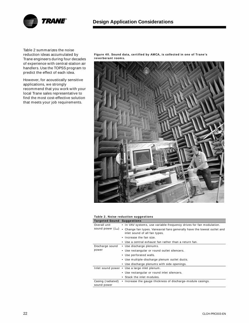
Table 2 summarizes the noise reduction ideas accumulated by Trane engineers during four decades of experience with central-station air handlers. Use the TOPSS program to predict the effect of each idea.
However, for acoustically sensitive applications, we strongly recommend that you work with your local Trane sales representative to find the most cost-effective solution that meets your job requirements.
Figure 40. Sound data, certified by AMCA, is collected in one of Trane’s reverberant rooms.
Table 2. Noise reduction suggestionsTargeted Sound SuggestionsOverall unit sound power (Lw)
• In VAV systems, use variable-frequency drives for fan modulation.
• Change fan types. Vaneaxial fans generally have the lowest outlet and inlet sound of all fan types.
• Increase the fan size.
• Use a central exhaust fan rather than a return fan.Discharge sound power
• Use discharge plenums.
• Use rectangular or round outlet silencers.
• Use perforated walls.
• Use multiple-discharge plenum outlet ducts.
• Use discharge plenums with side openings.Inlet sound power • Use a large inlet plenum.
• Use rectangular or round inlet silencers.
• Stack the inlet modules.Casing (radiated) sound power
• Increase the gauge thickness of discharge-module casings.

Design Application Considerations
CLCH-PRC003-EN 23
Typical Application ConsiderationsThe first things to consider when selecting an air handler for any given application include:
• Design. What overall system design best suits the required function?
• Arrangements. What is the best module arrangement for the specified function and layout?
• Components. Which components should be selected to support the function, layout, and arrangement of the application?
Air-Handling System
Design
After determining the required airflows and functions for a particular application, the HVAC designer must determine which one of two path layouts for outdoor air best serves the application: single-path or dual-path.
Single-Path Design (Figure 41)
Single-path AHUs rely on one outdoor air path. Depending on application requirements, that path may provide ventilation air only or both ventilation air and economizing air for natural, non-mechanical cooling. Components for filtering and tempering the air are arranged in series. The single-path layout can accommodate passive or powered return- and/or exhaust-air paths as well as energy recovery.
Dual-Path Design (Figure 42)
Dual-path AHU layouts provide two air paths. Like a single-path design, dual-path designs can incorporate basic outdoor air, recirculation, exhaust-air, and energy-recovery functions. However, one path is dedicated to handling ventilation air to specifically address ASHRAE Standard 62.1 requirements. Each path is provided with its own air treatment components such as filters and heating and cooling coils.
Figure 41. Single-path design
Figure 42. Dual-path design

Design Application Considerations
24 CLCH-PRC003-EN
A dual-path AHU design:
• reduces or eliminates reheat requirements, while providing an effective means of dehumidification for loads with low sensible-heat ratios (high latent cooling requirements)
• avoids increasing supply-fan static pressure due to high pressure drop components in the ventilation air stream (increases latent cooling and filtration capacity without increasing fan size)
• permits downsizing of the ventilation-path components
• enables compliance with the ASHRAE Standard 62.1 requirement for measuring outdoor airflow without significantly increasing the first cost of the air handler
• provides a cost-effective means to increase ventilation airflow in an existing system
• reduces cost by reducing the number of units (dedicated outdoor-air units can be eliminated)
Standard AHU
Arrangements
To complete the AHU system, the modules must be physically arranged in a way that fits the available space. Conventional descriptions of AHU arrangements, draw-thru and blow-thru, reflect the means of establishing airflow through the coil based on the position of the coil relative to the fan: the fan either draws air through a coil located upstream or blows air through a downstream coil.
The M-Series air handler adds another dimension to air handler arrangements, letting you combine modules by stacking them on top of each other in space-saving configurations, by coupling them together in a side-by-side arrangement with transition panels, or by combining both techniques. Careful evaluation of the merits of each arrangement is a critical part of the design process.
Draw-Thru Arrangements
A draw-thru AHU arrangement places the coils and filters upstream of a ducted supply fan. It can be single- or dual-path.
Figure 43. Horizontal draw-thru arrangement
Figure 44. Vertical draw-thru arrangement
Horizontal Draw-Thru (Figure 43)
Accepted system design practices are generally the only restrictions in a horizontal draw-thru application. However, certain application rules must be followed to promote proper airflow through filters and coils.
Vertical Draw-Thru (Figure 44)
M-Series air handlers in a vertical draw-thru arrangement typically result in a shorter footprint than horizontal draw-thru units. This arrangement stacks a fan on top of a vertical coil module. When designing an air handler in this configuration:
• The bottom deck must be equal to or longer than the fan module to avoid creating a “cantilever” effect
• Fan performance in CLCH-PRC008-EN (October 2004) for A, B, D, E, F, and G fans in vertical draw-thru applications include derates found in Table 3 to account for the airflow impingement by coils installed in vertical coil modules. TOPSS includes these derates in the selection of fans when installed in a vertical draw-thru application.
Table 3. Derates for vertical draw-thru applications
AF Fans FC FansBHP Multiplier 1.110 1.090RPM Multiplier 1.035 1.025

Design Application Considerations
CLCH-PRC003-EN 25
Blow-Thru Arrangements
This type of AHU arrangement places the cooling coil downstream of the supply fan.
Single-Zone Blow-Thru (Figure 45)
This type of arrangement can provide only one supply-air temperature from the unit. To promote proper air distribution through each module and to reduce the risk of moisture carryover, certain application considerations apply based on the fan type. See Trane product catalog CLCH-PRC008-EN for more information about choosing fans.
Multizone Blow-Thru (Figure 46)
This arrangement provides multiple supply-air paths with varying supply-air temperatures. It consists of a multizone coil module immediately downstream of a fan module. A separate thermostat serves each zone.
When designing an air handler in this configuration, use:
• zone dampers to blend the air from the “hot” and “cold” decks of the unit and produce the desired temperature for each zone.
• baffles to equalize the pressure drops over both decks (the TOPSS selection program selects baffles automatically).
• three-deck multizones with bypass deck, available as a custom option.
Note: Be aware that ASHRAE Standard 90.1 does not allow for multizone configurations without bypass for new construction.
Stacked Units
A stacked AHU arrangement can be either draw-thru or blow-thru. It places the air handler modules on top of each other. This strategy can significantly reduce the length of the unit and provide better acoustical performance, yet has very little effect on unit static pressure drops.
Figure 45. Single-zone blow-thru arrangement
Figure 46. Multizone blow-thru arrangement
Application considerations:
• Stacked module weight must not exceed the maximum stacking weight of the casing.
• Ductwork and dampers must not interfere with stacked modules.
• “Upper-deck” modules cannot overhang lower modules.
• Intermediate channel spacers should be used if the width of the upper deck is less than that of the bottom deck.

Design Application Considerations
26 CLCH-PRC003-EN
AHU Arrangements for Specific ApplicationsDraw-thru and blow-thru M-Series arrangements can be engineered for specific applications, including those to maintain proper building pressure, dehumidify, and recover energy.
Maintain Proper
Building Pressure
Return fans and exhaust fans are used to maintain building pressurization. An M-Series air handler can include either of these components. To better understand the differences between exhaust-fan and return-fan systems, consult your local Trane sales engineer or refer to the Trane applications engineering manual, Building Pressurization Control (AM-CON-17).
Figure 47. Return fan and economizer arrangement
Figure 48. Exhaust fan and economizer arrangement
Building Pressurization with a
Return-Fan-and-Economizer
Arrangement (Figure 47)
Figure 47 depicts a standard M-Series unit with a return fan and an economizer for outdoor air. The return fan typically runs continuously to balance the amount of air supplied to and removed from the occupied space. Although this approach makes precise space pressurization control more difficult, it is better suited to applications with high return static pressures than the exhaust-fan alternative. If the supply fan is unable to handle system static pressure, the return fan is sized to overcome the external static pressure of the return duct. Of course, the larger size and constant operation of the return fan also mean higher first and operating costs.
Application considerations:
• Size the supply fan to handle the static pressure requirements of a 100-percent economizer operation, including outdoor-air ductwork, dampers, filters, coils, other accessories in the outdoor
air stream, and supply-duct static pressure.
• Size the return fan to handle the static pressure requirements of a 100-percent return air operation, including return duct, exhaust duct, and exhaust damper.
• Control the return fan to keep the outdoor/indoor static-pressure differential within design limits.
• Control the mixing box dampers to prevent all of them from closing simultaneously; otherwise, serious equipment damage could result.
Building Pressurization with
Exhaust-Fan-and-Economizer
Arrangement (Figure 48)
Figure 48 depicts a standard M-Series unit with an exhaust fan and an economizer for outdoor air. To balance the amount of air exhausted from the building with the amount of air brought into the building, the exhaust fan modulates, running at full capacity only when the economizer brings in 100-percent outdoor air. When the economizer is at minimum and the

Design Application Considerations
CLCH-PRC003-EN 27
exhaust fan is idle, dampers on the mixing box close to prevent outdoor air from being drawn into the air handler through the exhaust module.
The exhaust-fan-and-economizer combination provides strict space pressurization control, provided that the supply fan is sized to handle total system static pressure. Its first cost and operating cost are usually lower than the return-fan-and-economizer alternative, too. (An exhaust fan requires less capacity than a return fan and runs less often.)
Application considerations:
• Size the supply fan to handle the static pressure requirements of the higher of either a 100-percent economizer operation or 100-percent return-air operation.
• Size the exhaust fan to handle the static pressure requirements of a 100-percent return-air operation, including return duct, exhaust duct, and shutoff damper, when the unit is in full economizer mode.
• Control exhaust airflow to keep the outdoor/indoor static-pressure differential within design limits.
• Control the mixing box dampers to prevent all of them from closing simultaneously; otherwise, serious equipment damage could result.
Dehumidify
Excessive humidity in buildings can encourage mold and mildew growth and thermal discomfort. To cost effectively address these issues, first isolate the conditioned space from the unconditioned space. (See Trane applications engineering manual, Managing Building Moisture, SYS-AM-15.) Next, remove the humidity.
The two primary humidity sources in most buildings are people and outdoor air. In any coil-based HVAC system, it is the cooling coil that dehumidifies the air. This coil must
be on and air must pass through it for dehumidification to occur. In M-Series enhanced dehumidification units, the priority for cooling coil control is humidity control. Temperature control is secondary and is generally provided by a separate reheat source.
Dehumidification can be obtained using:
• SDU (split dehumidification unit) arrangements
• CDQ™ (Cool, Dry, Quiet) units with desiccant wheels
• series, coil runaround loops
• air-to-air, fixed-plate heat exchangers
Free reheat options with dehumidification include:
• hot water heat-recovery coils
• refrigerant heat-recovery H coils
Dehumidification with a Split
Dehumidification Unit (SDU)
Arrangement (Figure 49)
The SDU is a dual-path, return-air-bypass air handler. It consists of two units that are stacked together in a draw-thru arrangement and that share one supply fan. All of the ventilation (outdoor) air is ducted to
Figure 49. Horizontal M-Series split dehumidification unit
the upper unit where it is dehumidified, typically down to 50ºF or lower.
The lower unit is sized to handle the return air needed to achieve the desired air-change rate in the space. The warmer return air in the lower unit mixes with the cooler, drier air from the upper unit. The resulting mixed air provides humidity control by achieving a sensible heat ratio (SHR) of down to 0.4, but also provides sensible reheat without using any new energy.
A vertical unit stacks the supply fan on top of a vertical coil module; the outdoor air enters the back of the fan module. This unit is shorter than the horizontal SDU.
Outdoor air economizers can also be used with an SDU. Simply add a mixing module to the return-air unit and bring outdoor air into this mixing module when conditions permit economizing.

Design Application Considerations
28 CLCH-PRC003-EN
The M-Series SDU:
• is a single-duct, factory-packaged dehumidification unit.
• does not require site-installed structural bracing
• provides excellent humidity control in recirculating units, achieving SHR down to 0.4 without using new energy for reheat
• can offer significantly lower operating costs and a low first cost
• Has a small footprint
• Can be used in retrofits due to its modular construction
• Uses standard M-Series components
• Is available in sizes 3 to 30, with the upper unit being equal to or smaller than the lower unit
For application guidelines concerning SDUs, refer to Trane engineering bulletin CLCH-PRB005-EN.
Figure 50. Dehumidification with Trane CDQ (Cool, Dry, Quiet) units
Dehumidification with CDQ™ (Cool,
Dry, Quiet) Desiccant Wheels
(Figure 50)
The addition of the CDQ desiccant wheel to the system enhances the dehumidification performance of the traditional cooling coil. The CDQ wheel transfers water vapor and the cooling coil does all the dehumidification work in the system. The latent capacity of the cooling coil increases without increasing its total cooling capacity. The system can achieve a lower supply air dew point without lowering the coil temperature. Unlike a system with a cooling coil alone, the dew point of the air leaving the coil can be lower than the dry bulb temperature leaving the coil.
• Increased cooling coil latent (dehumidification) capacity
• Lower achievable supply-air dew points.
• Decreased need for reheat
• Lower unit cooling sensible heat ratios.
• Warmer required chilled water temperatures.
• Improved energy efficiency for dehumidification.
• Decreased required cooling capacity when dehumidifying.
• Eliminates exhaust air as a requirement
For application guidelines concerningCDQ, refer to Trane engineering bulletin CLCH-PRB020-EN.

Design Application Considerations
CLCH-PRC003-EN 29
Dehumidification with Coil
Runaround Loops (Figure 51)
Series, coil runaround loops consist of finned-tube water coils connected in a closed loop that is “wrapped” around an active cooling coil. Operation is psychrometrically similar to the air-to-air, fixed-plate heat exchanger. The first coil in the loop precools the incoming outdoor air. The active cooling coil absorbs more heat from the air stream and further dehumidifies the air to the design point. The second coil in the loop is placed after the active cooling coil and reheats the air with the heat absorbed by the first coil. Loop components include a pump to move the fluid within the loop and an expansion tank.
Series, coil runaround loops occupy little space and have a relatively low first cost. Like the series air-to-air, fixed-plate heat exchangers, series coil loops are only effective during the cooling season. Additional heating may be required on cool, humid or cold days.
Series, coil runaround loops:
• Provide free reheat at design conditions
• Allow downsizing of new energy cooling and reheat coils
• Add a minimal pressure drop through each coil (only 0.4 to 0.6 in. wg)
• Are available in all M-Series units
• Can be fully modulated by varying water flow
Dehumidification with Air-to-Air,
Fixed-Plate Heat Exchangers
(Figure 52)
This arrangement creates a dedicated, 100-percent-outdoor-air unit that provides dehumidified ventilation air to a space at room-neutral temperature. It is used in conjunction with additional recirculating air handlers or fan-coil units that handle the sensible cooling load at the space. It is also used where the ventilation cooling load accounts for the majority of the system cooling load and in humid environments where comfort and moisture control are the primary concerns.
Figure 51. Series dehumidification with coil runaround loops
Figure 52. Series dehumidification with air-to-air, fixed-plate heat exchanger
This type of system matches the volume of the ventilation air to the current occupancy level without changing the humidity of the air delivered to the system zones. Ventilation air first enters the air-to-air, fixed-plate heat exchanger; there, the air is precooled below the outdoor-air dew point, reducing the latent load on the coil. The ventilation air then goes through the cooling coil where it is cooled to the desired supply-air dew point. Finally, it is reheated to room-neutral temperature as it flows through the heat exchanger again. See Figure 52.

Design Application Considerations
30 CLCH-PRC003-EN
To prevent the exchanger from overheating the air during summer design conditions, it may be necessary to add an optional outdoor-air, face-and-bypass damper to the heat exchanger. Overheating the air may further reduce the cooling load on the ventilation unit; however, this additional sensible load must be added to the space-sensible cooling devices.
At summer design conditions, using an air-to-air, fixed-plate heat exchanger in a series dehumidification application typically:
• can reduce ventilation cooling loads by 25 to 30 percent and eliminate the need of reheat.
• saves 40 to 50 percent of the ventilation unit energy at summer peak conditions.
• allows downsizing of the cooling and reheat coils.
During most part-load conditions, the percent of energy saved increases, though additional reheat may be needed.
Figure 53. Typical heat recovery refrigerant coil
Dehumidification with Heat-
Recovery Refrigerant Coils
(Figure 53)
This dehumidification strategy also uses waste compressor heat to provide free dehumidification reheat. An auxiliary condenser coil, the Trane Type H refrigerant coil, is installed downstream of the active cooling coil. Hot gas leaving the compressor flows through the H coil to the condenser. Many direct-expansion applications require dehumidification control and are suitable for refrigerant heat recovery. Examples include supermarkets, computer rooms, and schools.
Refrigerant heat-recovery coils:
• work with recirculating or 100-percent makeup-air units.
• provide excellent humidity control at any sensible-heat-ratio condition without using new-energy reheat.
• can reduce operating costs significantly.
• can be used in retrofits.
• use standard M-Series components.
• provide proven, low-cost technology.
Dehumidification with Hot-Water
Heat-Recovery Coils
Using waste condenser heat from the chiller or compressor is a simple way to provide dehumidification reheat. With this dehumidification strategy, an M-Series hot-water coil is installed after the active cooling coil. Hot water from the chiller—or from an auxiliary condenser on the chiller—is piped to this coil. Free reheat is available any time the chiller is on.
Hot-water heat-recovery coils:
• work with recirculating or 100-percent makeup-air units.
• provide excellent humidity control at any sensible-heat-ratio condition without using new-energy reheat.
• can reduce operating costs significantly.
• can be used in retrofits.
• use standard M-Series components.
• provide proven, low-cost technology.

Design Application Considerations
CLCH-PRC003-EN 31
Energy Recovery
Trane M-Series air handlers offer three high-performance solutions for airside energy recovery:
• Total-energy recovery wheels
• Runaround coil loops
• Air-to-air, fixed-plate heat exchangers
Each of these technologies transfers energy between the exhaust and outdoor air streams. Total energy recovery wheels transfer both sensible and latent energy between the air streams, while the coil loop and air-to-air, fixed-plate heat exchanger transfer sensible energy.
Energy-recovery arrangements of M-Series air handlers:
• reduce operating costs.
• can reduce first cost by allowing downsizing of chillers and boilers.
Energy-recovery systems can offer excellent energy savings when properly applied. Economic considerations must be carefully evaluated to determine the payback period of any energy-recovery system.
Consult Trane application manual, Air-to-Air Energy Recovery in HVAC Systems (SYS-APM003-EN), for more information.
Energy Recovery with a Total-Energy
Wheel (Figure 54)
This type of application is used to recover energy and moisture from the exhaust air stream. The wheel preheats and humidifies the supply air during the winter season and precools and dehumidifies the supply air during the summer season. Figure 54 shows an M-Series arrangement with an exhaust fan, an economizer, and a total-energy wheel.
As the return air enters the unit, a portion is recirculated through the return-air damper and the remainder goes through the wheel and is exhausted to maintain the required building pressure. Outdoor air enters an outdoor-air damper, then goes through the wheel and mixes with return air. During the economizing mode, the energy wheel is not used, and both wheel bypass dampers are open to allow up to 100-percent outdoor and exhaust airflow.
If the energy wheel module is used in a VAV system or in a unit that supplies cold supply air, modulating the exhaust-air bypass damper at the wheel can prevent the air from overheating during onset of the heating mode. If frosting conditions exist, modulating the outdoor-air bypass damper at the wheel can prevent vapor in the exhaust air from freezing on the wheel. If bypass frost control is used as freeze protection for the wheel, add a blender module to adequately mix the outdoor and exhaust air streams. If bypass frost control is not used, add outdoor-air preheat or return-air reheat.
Energy Recovery with
Coil Runaround Loops (Figure 55)
Outdoor-air and exhaust-air coil runaround loops recover energy that would normally be exhausted. They precool the outdoor air during the cooling season and preheat the outdoor air during the heating season. With coil loops, the outdoor and exhaust air streams do not need
Figure 54. Energy-recovery with a total-energy wheel
to be adjacent. This provides design flexibility for building renovations and new construction—at a first cost that is often lower than other methods of energy recovery.
Multiple exhaust and outdoor-air coils can be piped together with relative ease. Coil runaround loops use finned-tube hydronic coils in a closed loop to transfer energy. A typical runaround system is shown in Figure 55. The heat-transfer fluid pumped within the loop is usually an inhibited solution of ethylene glycol and water to avoid freeze up.
Coil loops offer complete separation of the air streams, thus eliminating any risk of cross-contamination. Loop components include the coils, a pump, expansion tank, and a three-way valve or variable-frequency drive (VFD). The expansion tank accommodates expansion and contraction of the internal fluid. The three-way valve or VFD modulates coil capacity. To prevent moisture in the exhaust air from freezing on the exhaust coil, the three-way valve can divert the warm fluid returning from the exhaust coil to the supply side of the coil.

Design Application Considerations
32 CLCH-PRC003-EN
Application considerations:
• Typical coil-loop effectiveness ranges from 45 to 65 percent with equal airflow and no condensation. Adhere to standard guidelines regarding coil construction, based on conditions. (See Trane catalog COIL-DS-1 and engineering bulletin COIL-EB-19 for more information.)
• Coil performance and airside pressure drops can be determined using Trane selection tools.
Energy Recovery with Air-to-Air,
Fixed-Plate Heat Exchangers
(Figure 56)
This arrangement is usually employed to recover sensible energy. It is more cost-effective in smaller units (less than 10,000 cfm). It is also used in cases where cross-flow issues are critical.
The exchanger preheats the supply air during winter and precools the supply air during summer. The optional frost-protection damper mounted on the outdoor-air face of the heat exchanger closes if the temperature drops below freezing at the cold corner of the exchanger (the leaving-exhaust-air corner, toward the outdoor air). The frost-protection damper reduces the recovery effectiveness of the heat exchanger and minimizes the amount of outdoor airflow at the cold corner as well as the possibility of frost forming on the exchanger. Also, if the air handler is designed to
deliver cold supply air, an optional face-and-bypass damper mounted on the exhaust side of the exchanger is needed to prevent the heat exchanger from recovering too much energy from the warm exhaust air when it is not needed. Using exhaust air energy recovery can significantly decrease the cooling and heating load on the system.
Figure 55. Energy recovery with a runaround coil loop
Figure 56. Energy recovery with an air-to-air, fixed-plate heat exchanger (100 percent outdoor air)
Trane’s Energy Recovery Performance (ERP) program can calculate total-energy wheel performance and determine if frost protection is needed. Contact your local Trane sales representative for more information about the ERP program. (See Trane engineering bulletin CLCH-PRB012-EN for more information.

CLCH-PRC003-EN 33
M-Series Modules and Application Considerations
M-Series air handlers adopt a “building-block” approach to AHU design. Each building block, or module, contains one or more components that serve a specific purpose unique to each application. The required function, layout, and arrangement of the air-handling system determine which modules must be included for a particular application.
Access/Blank and Turning ModuleAccess or blank modules can be incorporated into the air handler design to provide access to internal components for cleaning, maintenance, and service or to promote proper airflow through the unit.
A turning module is a blank module that alters the direction of airflow and reduces turbulence. It can also serve as an effective sound attenuator. When compared to a field-mounted, rectangular duct silencer, the turning module is less expensive to install, has a lower pressure drop, and provides more predictable performance. Perforated lining in the turning module attenuates mid- to high-frequency sound.
Note: Only large and extra-large blank modules can be selected as turning modules.
Blender ModuleBlender modules contain air-mixing baffles, or blenders, that impart rotational energy to the passing air streams, boosting their velocity for improved mixing. It is usually placed immediately downstream of a mixing box module and upstream of filters and coils. Figure 58 documents blender module performance at a downstream coil entering air temperature of 55ºF and return-air temperatures of 70ºF and 75ºF.
Application considerations:
• The face velocity of the blender should exceed 400 fpm for proper mixing.
• When operated at temperatures within its design range, the blender module may eliminate the need for preheat.
Figure 57. Blender module performance with 55ºF leaving air temperature
• The M-Series blender module allows complete air mixing.
• Select the mixing box module such that the dampers are positioned at the top, back, or bottom when used with a blender module.
Figure 58. Blender module

M-Series Modules and Application Considerations
34 CLCH-PRC003-EN
CoilsCoil modules temper all (full-face) or part (modified-size) of the passing air stream by heating, cooling, or dehumidifying it with a factory-mounted coil. To select the right coil for the unique requirements of the application, be sure to optimize its capacity, face velocity, pressure drop, and construction. The unique H-fin design from Trane permits coil selections with face velocities in excess of 625 fpm without moisture carryover.
Table 4 shows the application considerations for the various coil types. Table 5 summarizes the available sizes for Trane coils.
M-Series Climate Changer™ air handler coil performance is certified in accordance with ARI Standard 410. Coils containing ethylene glycol
Table 4. Coil application considerationsCoil type Application considerationsHydronic cooling and refrigerant (direct expansion) cooling
• Size the coil to prevent moisture carryover due to high airflow velocities. The high-efficiency design of Trane Type H fins allows much higher face velocities than traditional coils. It is possible to exceed 625 fpm face velocities without moisture carryover. Refer to the moisture carryover curves in the “Coil Data” section for velocity limits.
• Properly size the condensate trap to provide positive drainage.
• Specify two-way-sloped drain pans to eliminate level seams and promote condensate flow directly to the drain outlet. Use stainless-steel construction to extend drain-pan life.
• Provide adequate freeze protection for chilled hydronic coils.Hydronic heating • Hot-water heating is an attractive option for buildings without a ready source of steam. Hot water from the chiller
condenser circuit is excellent for providing free dehumidification reheat.
• Providing effective freeze protection is more challenging with hot-water preheat coils than it is for steam. To minimize the risk of coil freeze-up, use face-and-bypass preheat coils and operate the hot-water coil at full capacity.
Steam heating • Properly pipe and trap the coil to provide positive drainage.
• Steam coils are less susceptible to freeze-up than hot water coils. Trane Type N and NS steam-distributing coils use steam pressure to blow condensate from the coil. Double-trap the coil for a virtually freeze-proof installation.
Table 5. Trane coil sizesCoil tube sizes Description1/2-inch OD (outside diameter)
Available in one face-area size per unit size
Copper tubes
0.016-inch or 0.025-inch tube wall options
Available in 2, 4, 6, or 8 rows
Aluminum fins available only; baked phenolic coatings optional5/8-inch OD Available in three face-area sizes: unit (full face area), modified, and hot deck
Available in 1–4, 6, 8, or 10 rows in all sizes except hot deck (Hot deck coils are available in one or two rows.)
Available with 0.020-, 0.024- or 0.035-inch tube walls, typified by 5/8-inch OD tubes
Available with aluminum or copper fins, with or without baked phenolic coatings1-inch OD Can be selected in unit and modified sizes
Modulating, steam-distributing-type coils, available in one row only
Available with 0.031-inch thick copper tubes or 0.049-inch thick red brass tubes and aluminum or copper fins.
Available with aluminum or copper fins, with or without baked phenolic coatings
are also rated in accordance with ARI Standard 410. Propylene glycol and calcium chlorate, or a mixture thereof, are outside the scope of ARI Standard 410.
Typical coil-face velocities are 200 to 625 fpm for cooling and 200 to 800 fpm for heating. The convention to determine the coil connection side of a single-level unit is to stand at the leaving air side of the coil with the air blowing in your face.
1/2-Inch Unit Coils
One-half-inch unit coils may be selected for these applications:
• Chilled water
• Hot water
• Direct-expansion (DX) refrigeration (R22)
These coils have aluminum fins and are available with or without baked phenolic coating. All 1/2-inch chilled-water unit coils have copper headers with external-threaded steel-pipe connections.
Table 6. 1/2-inch unit coil typesUW • Chilled water or hot water
• General purpose
• Single-row serpentine
• 2, 4, 6, or 8 rowsUU • Chilled water or hot water
• Dual-row serpentine
• Low water-pressure drop
• High flow rate
• 4 or 8 rows
• Unit sizes 12–120 onlyUF • Refrigerant
• Standard, intertwined, and horizontal-split circuiting
• 4, 6, or 8 rows

M-Series Modules and Application Considerations
CLCH-PRC003-EN 35
5/8-Inch Unit Coils
Five-eighths-inch unit coils may be selected for these applications:
• Chilled water
• Hot water
• DX refrigeration (R22)
These coils are available with aluminum fins (with or without baked phenolic coating) or copper fins (with or without baked phenolic coating). All 5/8-inch chilled-water unit coils—except P2, P4, P8, 1-row W, DD, and TT coils—have copper headers with external-threaded steel-pipe connections.
Table 7. 5/8-inch unit coil typesW • Chilled water or hot water
• Single-row serpentine
• 1, 3, 4, 6, 8, or 10 rowsOne-row W coils have opposite-end connections.
D • Chilled water
• Single-row serpentine
• Drainable at each row
• 4, 6, 8, or 10 rows
5W • Chilled water or hot water
• Same-end connections
• 1 or 2 rows
DD • Chilled water
• Dual-row serpentine
• Low water-pressure drop
• High flow rate
• Drainable at each row
• 4, 6, 8, or 10 rows Six- and 10-row coils have opposite-end connections.
WD • Chilled water or hot water
• Dual-row serpentine
• Low water-pressure drop
• High flow rate
• 6, 8, or 10 rows
• Unit sizes 10–120 only
K • Chilled or hot water
• Single-row serpentine
• Drainable at each row
• Cleanable tubes
• 2, 4, 6, 8, or 10 rows
5D • Chilled water or hot water
• Dual-row serpentine
• Horizontally split
• Dual supply and return connections
• Low water-pressure drop
• High flow rate
• 6, 8, or 10 rows
• Unit sizes 21–120 only
P2, P4, P8 • Chilled water
• Ultra-low flow rate
• P2—two-tube feed (2, 4, or 6 rows)
• P4—four-tube feed (2, 4, 6, or 8 rows)
• P8—eight-tube feed (4 or 8 rows)
5A • Hot water
• Alternate-tube feed
• Low flow rate
• 2 rows
F • Refrigerant
• Standard and horizontal circuiting
• 2, 4, 6, or 8 rows
WA • Hot water
• Alternate-tube feed
• Low flow rate
• 1 row
• Opposite-end connections
TT • Hot water
• Low flow rate
• Common duct coil
• Two-tube feed
One-Inch Steam Coils
All 1-inch unit coils are steam coils. They are available with aluminum fins (with or without baked phenolic coating) and copper fins (with or without baked phenolic coating). One-inch steam coils are one-row coils and have cast iron headers with internal-threaded pipe connections.
Type N and Type NS
• Modulating steam
• Steam-distributing type
• NS—same-end connections
• N—opposite-end connections
• One row
Modified Coils
Modified coils are 5/8-inch and 1-inch tube coils with reduced face areas. Use them with internal face-and-bypass dampers or in low-capacity applications.
Hot-Deck Coils
Hot-deck coils are used in the hot decks of multizone units and are available in all types of one-row and two-row heating coils with 5/8-inch and 1-inch tubes.
Figure 59. Typical 5/8-inch coil
Figure 60. Typical 1-inch steam coil

M-Series Modules and Application Considerations
36 CLCH-PRC003-EN
Integral Face-and-
Bypass Coil
Conventional preheat systems are subject to coil freeze-up, stratification, and air-volume variation. The integral face-and-bypass (IFB) coil is specifically designed to minimize these problems, alternating heating and bypass channels with face-and-bypass dampers before and after the coil. If heat is needed, both dampers modulate open; otherwise, they remain closed to prevent “coil wiping” on the leaving side of the coil and to avoid unwanted heat pickup. This design effectively provides good freeze protection, constant airflow, and uniformly mixed and unstratified air.
The IFB coil comes as a complete package (including heating coil, linkage, and dampers), thus assuring maximum system reliability. The module uses horizontal coil-tube arrangements in unit sizes 3 to 40 and vertical coil-tube arrangements in unit sizes 50 to 120.
• Size 3 units require a large module immediately downstream of the coil.
• Unit sizes 6 to 40 require a medium module immediately downstream of the coil.
• Unit sizes 50 to 120 require an extended-medium module immediately downstream of the coil.
Air-to-Air, Fixed-Plate Heat ExchangerAn air-to-air, fixed-plate heat exchanger is used to reclaim exhaust-air energy as well as to provide dehumidified ventilation air to a space at room-neutral temperature. It is a sensible-energy-recovery device that consists of alternate layers of aluminum plates that are separated and sealed to form passages for the outdoor and exhaust air streams. This design minimizes cross-contamination and relies on thermal conduction to induce heat transfer. It is also easy to clean and service.
The fixed-plate surface is uniquely designed to equalize uneven entering airflow as the air travels through the heat exchanger. Air can enter the module on any side except the bottom, where there are drain pans to catch condensate.
An optional Trane frost-protection damper (see Figure 61) discourages icing, permitting exchanger operation at ambient temperatures as low as -20ºF. A factory-applied PVC (polyvinyl chloride) coating is available for high-temperature (140º–400ºF) or corrosive applications.
Application considerations:
• The heat exchanger module is available as a custom option for M-Series air handlers in 10 unit sizes ranging from 3 to 30. Two heat exchanger options per size and three plate-spacing options per heat exchanger for most unit sizes give substantial performance flexibility.
• Recovery is limited to primarily sensible energy; effectiveness typically ranges from 50 to 70 percent or about equal to an eight-row coil loop.
• M-Series heat exchanger has a pressure drop of 0.6 to 1.0 in. wg per side.
• A frost-protection damper is required if the outdoor air drops below the frost formation point (typically around 20ºF, but possibly as high as 32ºF).
• Optional face-and-bypass dampers (see Figure 66, p. 38) can bypass exhaust air through the exchanger to provide capacity control.
• The maximum pressure differential between the two air streams in the heat exchanger is 6 in. wg.
• Factory coatings are available for high temperature and/or corrosive air streams.
• If located directly downstream of a fan, put a 90-degree discharge plenum or diffuser module between the fan and the exchanger.
• Do not apply fixed-plate heat exchanger modules in systems where toxic or harmful gases must be isolated from the supply air stream.
Figure 61. Frost-protection damper

M-Series Modules and Application Considerations
CLCH-PRC003-EN 37
DiffuserA diffuser module consists of pressure-equalizing baffles that are designed to provide even airflow across components downstream of a fan. The diffuser module is typically used immediately downstream of a centrifugal fan in a blow-thru filter, coil, or silencer application.
Discharge Plenum
Before leaving the air handler, supply air can be ducted to a discharge plenum module. The rapid air-stream expansion as it passes into the plenum reduces turbulence and creates an acoustical end reflection that dampens low-frequency sound. Two configurations enable supply-duct connections from any side:
Figure 62. Diffuser modules provide even airflow.
Figure 63. Discharge plenums can lessen low-frequency sound.
• Vertical-mounted plenum modules mount atop an adjacent module. Openings can be factory- or field-cut.
• Horizontal-mounted plenum modules mount on the front of an adjacent module. Openings can be factory- or field-cut.
Note: All discharge plenum modules are available with 2-inch, insulated casing walls of solid or perforated construction, or with 4-inch perforated, double-wall casings to further attenuate high-frequency sound.
Electric HeatElectric heat is a relatively inexpensive first cost heating option compared to central plant boiler systems. The M-Series air handler has a factory-installed, UL-listed, electric heat option for unit sizes 3 to 66 in constant-volume or VAV applications.
Application considerations:
• Blow-thru arrangements require a minimum of a medium blank module between the supply fan and the electric heat module to ensure even air distribution across the electric heater.
• A large access or discharge plenum module with a door for field-wiring access is required downstream of the electric heat module in a blow-thru arrangement.
Figure 64. M-Series factory-installed electric heat option is UL-listed.
Energy WheelM-Series energy wheel module is a total-energy-recovery device; it recovers both sensible and latent energy. The energy wheel module consists of a rotating wheel that contains heat exchange media surfaces. A desiccant material specifically designed for absorption and desorption of water vapor is permanently bonded into the heat exchanger matrix. The wheel rotates between the outdoor- and return-air paths, whose air streams are counter-flow.
Energy wheels are sized based on the ventilation air requirement and can be applied in a 100-percent-outdoor-air unit or a recirculation unit. Internal wheel-bypass dampers vary the effectiveness of the wheel.
For more application information, refer to these Trane publications: engineering bulletin CLCH-PRB012-EN, catalog CLCH-PRC006-EN, and applications manual SYS-APM003-EN.
Figure 65. Energy wheel module

M-Series Modules and Application Considerations
38 CLCH-PRC003-EN
Highlights of the M-Series energy wheel module include the following:
• Certified in accordance to ARI Standard 1060
• Available in 13 sizes, depending on ventilation requirements ranging from 1,500 to 25,000 cfm
• Single wheels for M-Series sizes 3 to 50 with up to six wheels available per unit size
• Greater than 70 percent total effectiveness at a pressure drop of 1 to 1.15 in. wg and nominal airflow through the wheel
• Bypass dampers are standard for partial-flow energy wheel modules
• Standard, built-in return damper for partial-flow, recirculating wheels for sizes 6 to 50
• Module includes required space upstream and downstream of the wheel
• Required access and doors in module
• Variable effectiveness control using air bypass
• Frost protection using an air bypass damper or a separate preheat module
Face-and-Bypass DampersDesigned to divert airflow around a coil, the face-and-bypass damper module can be used to control humidity or provide freeze protection for hydronic coils. Face-and-bypass dampers are available in two module configurations, internal and external, and also in an integral face-and-bypass coil (see p. 36).
Internal Face-and-
Bypass Dampers
Typically used immediately upstream of a modified-size (less than 100-percent airflow) coil, this arrangement enables temperature control while operating the preheat coil at full flow. The dampers modulate to bypass air around the heating coil when the outdoor air is warm enough to preclude freezing.
Application considerations:
• To ensure full airflow coverage across downstream coil banks, provide extra distance (see Table 8) after the modified-size coil module.
• Consider the effect of reduced bypass area, higher velocities, and higher pressure drops when designing internal face-and-bypass configurations that require 100-percent bypass. External face-and-bypass dampers may be better suited for these configurations.
Figure 66. Face-and-bypass damper
External Face-and-
Bypass Dampers
External face-and-bypass dampers perform the same function as their internal counterpart. However, they are used upstream of a full-face coil, and they route air around the coil through an external bypass duct. See Table 9 for recommended duct sizes that permit 100-percent bypass. Duct placement varies with each air handler arrangement. Ensure that the external bypass duct does not interfere with stacked modules.
Use Table 9 in conjunction with Figure 68D.
Table 8. Recommended distance between coils to ensure full airflow coverage
Unit size Distance between coils (inches)
3, 6 128, 10 1812, 14 24
17 3021 33
25, 30, 35, 40 3650 48
57, 66 5780 69
100, 120 78
Table 9. Recommended bypass duct sizes (inches)Unit size H W L
3 12 27 126 14 40 148 14 44 1410 14 56 1412 18 60 1814 18 64 1817 18 70 1821 24 72 2425 24 74 2430 24 87 2435 28 91 2840 28 104 2850 28 115 2857 40 115 4066 40 132 4080 40 132 40100 40 147 40120 40 174 40

M-Series Modules and Application Considerations
CLCH-PRC003-EN 39
Figure 67. Internal face-and-bypass configurationFan Medium
CoilAccess
or blankInternal face-and-
bypassFilter mixing box
Figure 68. A. External face-and-bypass configurations
FAN MEDIUMCOIL BLANK
MODULE
SMALLCOIL
FAN MEDIUMCOIL
BLANKMODULE
SMALLCOIL
EXTERNALFACE-
AND-BYPASS
VERTICALCOIL MODULE
COIL EXTERNALFACE-
AND-BYPASS
FAN
BYPASSAIRFLOW
FAN
A
H L
EXTERNAL FACE-AND-BYPASS WITHBYPASS BETWEEN TWO COILS
Figure 68 C.
Figure 68 B.
Figure 68 D.
Figure 68 A.
Size 3-30
Size 35-100
A=The minimum module depth to allow even air distribution over the full face of the downstream coil at full bypass condition.B=Opening width (see Table 9)
Figure 68 B. Unit Size Blank Size
3-10 Small12-40 Medium50-57 Extended Medium66-120 Large
Figure 68 C.Area of opening in fan module should be equal to "H" and "W" dimensions from Table 9 on page 38.
PBCFMA
∆××
+=114.4
PBCFMA
∆××
+=114.5
P∇ = coil design air pressure drop of down-stream coil (in. w.g.)

M-Series Modules and Application Considerations
40 CLCH-PRC003-EN
FansDesigners can choose from four common fan types—airfoil (AF) and forward-curved (FC) centrifugal, airfoil plenum, and airfoil vaneaxial—to tailor air handler performance to application requirements. Table 11 on page 41 summarizes and compares the characteristics and application considerations of these fans. When evaluating the merits of each fan type for a given application, consider the volumetric rate of airflow, static pressure, required sound characteristics, and available space.
To verify that fan performance will satisfy design requirements, use the TOPSS selection program or refer to Trane fan performance catalog CLCH-PRC008-EN. The ARI Standard 430-certified fan curves include the fan module casing effect. The catalog also discusses how ductwork connections, air density, fan and motor heat, drive losses, and use of high-performance (greater than 65-percent efficiency) filters affect fan performance.
Depending on the fan-control method used, the fan can provide either a constant or variable volume of supply air. In a constant-volume system, the fan delivers a consistent amount of air and cooling and heating devices adjust the air temperature for occupant comfort. Because the fan runs at constant horsepower under all load conditions, system operating costs are higher than those of a VAV system.
Fan Identification
Each fan is identified by unit size and a letter. The letter defines the fan application; see below.
A VAV system provides occupant comfort by delivering a modulated amount of constant-temperature air. Usually, supply-duct static pressure determines how much air the fan provides. Varying fan horsepower with building load can offer substantial energy savings and do a better job of controlling space humidity.
Fan modulation is accomplished with a variable-frequency drive (VFD) that adjusts fan speed and airflow by varying motor speed. VFD modulation is quiet and energy efficient; it can also prolong the life of the fan motor by “soft starting” it.
Regardless of the fan control method used, it is important to provide a means of monitoring outdoor airflow. Over time, filter loading and other system effects can change static pressures and eventually reduce airflow—including ventilation airflow—below the design volume-flow rate.
Table 10. Fan identificationIdentifier Fan application
A Low pressure (housed)B Medium pressure (housed)
D, E High pressure (housed—large diameter)
F, G High pressure (housed—small diameter)
P Plenum (plug)Q Horizontal airfoil vaneaxial (Q™
fan, small diameter)R Horizontal airfoil vaneaxial (Q
fan, large diameter)V Vertical airfoil vaneaxial (Q™ fan,
small diameter)W Vertical airfoil vaneaxial (Q fan,
large diameter)
Figure 69. Typical FC fan
Figure 70. Typical Q fan

M-Series Modules and Application Considerations
CLCH-PRC003-EN 41
Table 11. Fan summary information
Fan typeFC Fan
Backward-curved (BC) Fan
AF Fan Model Q Fan Plenum Fan
Centrifugal, housed Centrifugal, housed Centrifugal, housed Vaneaxial UnhousedInlet Double Double Double Single SingleAirflow direction Radial Radial Radial Axial Pressurized, all
directionsOptimal pressure range
Low to medium (0 to 5 in. wg)
High (4 to 8 in. wg) High (4 to 8 in. wg) Medium (2 to 5 in. wg)
Medium (2 to 5 in. wg)
First cost (relative) Low Medium Medium High HighOperating cost (relative)
Medium Medium-high Medium-high Low Medium
Typical speed range 400–1,200 rpm 1,000–2,600 rpm 1,000–2,600 rpm 1,400–2,900 rpm 600–1,200 rpmBlade shape Curved Curved Airfoil Airfoil AirfoilAcoustical characteristics
Significant air turbulence that
quickly abates; little blade-tone noise
Significant air turbulence; strong
blade tones in 250-Hz octave band
Significant air turbulence; strong
blade tones in 250-Hz octave band
Little turbulence; quiet at hard-to-attenuate
low frequencies
Discharge sound similar to Q fan, but higher inlet noise1
Suggested source attenuation
Add a discharge plenum
Avoid using inlet vanes; use discharge
plenums and/or silencers
Avoid using inlet vanes; use discharge
plenums and/or silencers
Avoid using inlet vanes; use discharge
plenums and/or silencers
Add a discharge plenum or outlet/inlet
silencer
Direct upstream space required in draw-thru arrangements
None None None Medium module Medium module
Direct downstream space required in blow-thru arrangements
Medium blank or diffuser module
Medium blank or diffuser module
Medium blank or diffuser module
Two turning modules or a large module and
diffuser module
Medium blank module
When to use? Low-pressure applications
High-pressure applications
High-pressure applications
Quiet application, especially 6,000–
60,000 cfm
Multiple-duct arrangement, blow-thru applications2
Kt loss, abrupt discharge3
1.8 1.0 1.0 0.8 n/a
1. Add duct takeoff losses from the plenum fan module to external static pressure; see Trane fan performance catalog CLCH-PRC008-EN for details.
2. Same as Note 1; the uniform discharge velocity of the plenum fan may eliminate the need for turns in supply-air ductwork and diffusers, suiting it for installations with limited equipment room space.
3. In draw-thru applications, fan curves assume three diameters of straight duct downstream of the fan. Refer to AMCA 201-90, Fans and Systems, for more information when this assumption is not valid.

M-Series Modules and Application Considerations
42 CLCH-PRC003-EN
FiltersFilter modules contain particulate filtering media that remove contaminants from the passing air stream to improve IAQ. Filter options include high-performance (greater than 65-percent efficiency) pleated, bag, or cartridge filters. HEPA-type (99.97-percent efficiency) filters are also available. The continuous operating range of both the high-efficiency filters and the disposable prefilter is 0ºF to 150ºF.
Application considerations:
• Higher filter efficiencies cost more, but provide cleaner air and better system performance. National, state, and local codes may also specify filter performance.
• Filter resistance and first cost may increase with efficiency.
• High filtration efficiencies sometimes require more space, which lowers velocity, and may enlarge the air handler footprint.
• A high degree of filtration can lower cleaning costs in the occupied space.
• Exceeding the face velocity limit of the filter increases its resistance (as well as fan energy consumption) and necessitates more frequent maintenance or replacement.
• Use disposable prefilters with HEPA filters to enhance filtration efficiency and reduce filter replacement costs.
• Use disposable prefilters upstream of high-efficiency filters to increase the life of the filter and minimize replacement costs.
• Exercise special care to avoid moisture carryover whenever final filters are used. Never place a blow-thru final filter module directly downstream of a cooling coil without providing an intervening source of reheat (such as fan motor). Tests have shown that certain entering-coil conditions can create water vapor that will collect on the final filter. The only known solution for this intermittent application issue is two degrees of reheat.
• Treating filter media with an antimicrobial coating can reduce the likelihood of microbial contamination. Trane’s coated pleated media filters are treated with an antimicrobial coating.
• Always place HEPA filters in the last section of the air handler to prevent infiltration through the unit casing from degrading the otherwise high performance of the filter.
• Install bag filters with the pleats vertical to the floor of the unit.
• Provide easy access to encourage regular filter maintenance.
• High-efficiency filters and disposable prefilters may be operated up to 100 percent relative humidity; however, they may not come in direct contact with water droplets.
• Keep filters dry
Figure 71. Bag filter module (entering air side)
Figure 72. Bag filter module (leaving air side)
Figure 73. HEPA filter module

M-Series Modules and Application Considerations
CLCH-PRC003-EN 43
Gas HeatGas heat can be an economical source of heat in M-Series Climate Changer air handlers when compared to traditional sources of heating such as central plant boilers with hot water or steam coils installed inside air handlers, or electric resistance heating installed inside air handlers.
Gas heat can be a good heating option for any of the following applications:
• Climates and applications with large heat loads
• Applications with high outside air requirements to comply with ASHRAE Standard 62
• Buildings without a central boiler plant
• Remote locations where boiler capacity or water piping expense is prohibitive
• Areas with relatively inexpensive natural gas or expensive electricity
When considering gas heat as the primary heat source in an M-Series unit, include these application considerations:
Figure 74. Gas heat module
• Gas heater must be applied in a blow-thru configuration to insure that combustion gases will not enter the airstream due to the positive static pressure
• Maximum discharge air temperature is 101° F
• When reducing airflow, the control system should not allow the temperature rise through the gas heat section to exceed the nominal at full airflow.
• On high altitude applications, derate the heating capacity (MBh) by 4 percent for every 1,000 feet over 2,000 feet.
Additional information on gas heat features, options, applications, and installation can be found in Engineering Bulletin CLCH-PRB010-EN.
HumidifierASHRAE Standard 62.1 suggests maintaining a relative humidity of no less than 30 percent to provide a comfortable, healthy indoor environment. The M-Series air handler humidifier module uses low-pressure steam distributors to add moisture to the air. It includes accessories such as valves, strainers, and traps. Factory mounting within the air handler lowers the installed cost of the humidifier and keeps moisture out of the supply duct.
Application considerations:
• Airflow through the humidifier must be horizontal and of relatively uniform velocity (400 to 700 fpm).
• Do not locate the humidifier upstream of filters, gas heat, electric heat, or active cooling coils.
• Blow-thru applications with housed fans require at least a four-row coil between the fan and humidifier modules. The diffuser alone is unacceptable.
• To prevent condensate formation, the relative humidity leaving the humidifier should not exceed 83 percent. Contact your local Trane sales representative for application-specific guidance.
• The required dispersion distance is designed into the humidifier module.
• Vertical airflow turning immediately upstream and downstream of the humidifier module requires a large module.
IntakeAs its name implies, this module provides a means for outdoor air to enter the air handler. A screen on the intake opening prevents foreign objects from entering the air handler. The module also contains a moisture eliminator and a drain pan to remove water from the outdoor air stream if it enters the air handler.
Figure 75. Humidifier module

M-Series Modules and Application Considerations
44 CLCH-PRC003-EN
Mixing Box and Economizer
A mixing box module typically combines the incoming outdoor air with recirculated return air collected from the occupied space. It is commonly included in an air handler design to control this mixture. When equipped with an optional Traq damper, the mixing box module permits direct measurement of outdoor airflow to assure compliance with ASHRAE Standard 62.1.
Designed to measure and modulate outdoor airflow, the Traq damper assembly consists of one to six butterfly-type dampers. The bell-mouth inlet of each damper guides air uniformly through a flow-sensing ring that accurately measures total and static pressure from 15 to 100 percent of nominal airflow. The damper assembly’s ventilation control module produces a 2-to-10-Vdc signal that is proportional to airflow, recalibrates itself once every 60 seconds, and automatically adjusts for temperature variations.
Figure 76. Mixing Box
Application considerations:
• The Traq damper mixing box requires only one duct diameter of straight inlet duct (as much as 80 percent less than other airflow monitoring techniques).
• Connecting a Traq-damper-equipped air handler to a building automation system, such as a Tracer building management system, permits:
– Dynamic calculation of the outdoor air needed to adequately ventilate a multispace VAV system and reset the outdoor-air setpoint accordingly to save energy.
– Trend logs and custom reports to document compliance with ASHRAE Standard 62.1.
• An additional mixing box can be used as an economizer to provide an exhaust path for return air, allowing the main mixing box to provide natural, non-mechanical cooling when outdoor air conditions are suitable (see Figure 45 on page 25).
• Use freeze protection for coils downstream of the mixing box when incoming outdoor air is below 35ºF (see the “Protect Coils from Freezing” section on page 18).
Moisture EliminatorA moisture eliminator is used to remove entrained water from the passing air stream. It may also be used immediately downstream of a cooling coil module to prevent moisture carryover in single-zone blow-thru arrangements; however, it is not required with plenum-type fan modules.
MultizoneThe multizone module consists of a cooling coil, heating coil, and dampers with multiple zones. It is split into two decks, each with a separate air stream. The “cold” deck cools one air stream and the “hot” deck heats another air stream. The damper then mixes these two air streams to achieve a certain mixed-air temperature. The damper is divided into segments so that one AHU can deliver multiple supply air temperatures. Baffles ensure equal pressure drops through each deck of the unit.
The multizone module is always used in a blow-thru arrangement and is typically placed directly downstream of the supply fan.
Note: The number of zones that one multizone AHU can supply varies by unit size.
Note: Be aware that ASHRAE Standard 90.1 does not allow for multizone configurations without bypass for new construction.

CLCH-PRC003-EN 45
Quick Select
Selection Procedure
1 Size the air-handling unit based on airflow through the cooling coil (see Table 12). The unique fin design of Trane coils enables cooling coil selections at velocities in excess of 625 fpm with no moisture carryover. The coil moisture carryover curves from tested data are built into the Trane Official Product Selection System (the TOPSS™ program). Use this system to select coils.
2 Choose the coil module (see Table 13). Unit size, coil type, and coil rows determine the minimum coil module size required.
3 Select a filter type and check face velocities (see Table 14). The maximum recommended face velocity for pleated media, permanent, bag, and 12-inch cartridge filters is 625 fpm; for throwaway and HEPA filters, it is 500 fpm.
4 Design the basic air-handling system. Choose all required sections, including custom modules. Contact your local Trane sales office for more information on custom modules.
5 Estimate system static pressure requirements and select a fan (see Table 15). Refer to “Module Performance Data” on page 109 for pressure drops and catalog CLCH-PRC008-EN for fan curves.
6 Total the overall air-handling unit dimensions and weights. Use Table 16 for module dimensions and weights.
7 Select a control system. Factory-mounted, -wired, and -tested end devices, starters, VFDs, and direct-digital, interoperable controllers are available to minimize construction cycles and job-site coordination.
8 Contact your local Trane sales office to order an air-handling system or to ask questions.

Quick Select
46 CLCH-PRC003-EN
Table 12. Size the air-handling unit Coil type Unit size 3 6 8 10 12 141/2-inch unit Area (ft2) 3.32 5.86 7.54 9.64 12.30 14.22
Qty-Size 1-21.25 x 22.5 1-23.75 x 35.5 1-27.5 x 39.5 1-27.5 x 50.5 1-32.5 x 54.5 1-35 x 58.55/8-inch unit1 Area (ft2) 2.98 5.47 7.31 9.38 12.38 13.90
Qty-Size 1-19.5 x 22 1-22.5 x 35 1-27 x 39 1-27 x 50 1-33 x 54 1-34.5 x 585/8-inch modified
Area (ft2) 1.83 2.92 4.88 6.25 9.00 9.67Qty-Size 1-12. x 22 1-12 x 35 1-18 x 39 1-18 x 50 1-24 x 54 1-24 x 58
Coil type Unit size 17 21 25 30 35 401/2-inch Unit Area (ft2) 16.80 20.78 24.38 29.01 34.14 39.33
Qty-Size 1-37.5 x 64.5 1-45 x 66.5 1-51.25 x 68.5 1-51.25 x 81.5 1-57.5 x 85.5 1-57.5 x 98.55/8-inch Unit1 Area (ft2) 16.67 19.94 23.38 27.84 32.76 37.77
Qty-Size 1-37.5 x 64 1-43.5 x 66 1-49.5 x 68 1-49.25 x 81 1-55.5 x 85 1-55.5 x 985/8-inch modified
Area (ft2) 13.33 15.13 17.00 20.25 21.25 24.50Qty-Size 1-30 x 64 1-33 x 66 2-18 x 68 2-18 x 81 2-18 x 85 2-18 x 98
Coil type Unit size 50 57 66 80 100 1201/2-inch unit Area (ft2) 49.43 57.03 65.63 78.75 100.36 119.58
Qty-Size 2-32.5 x 109.5 2-37.5 x 109.5 2-37.5 x 126 2-45 x 126 2-51.25 x 141 2-51.25 x 1685/8-inch unit1 Area (ft2) 47.69 56.77 65.63 78.75 99.88 119.00
Qty-Size 1-30 x 109
1-33 x 109
2-37.5 x 10⁹ 2-37.5 x 126 2-45 x 126 2-51 x 141 2-51 x 168
5/8-inch modified
Area (ft2) 36.33 43.15 49.88 60.38 76.38 91.00Qty-Size 2-24 x 109 1-24 x 109
1-33 x 109
1-24 x 126
1-33 x 126
2-18 x 126
1-33 x 126
2-24 x 141
1-30 x 141
2-24 x 168
1-30 x 168(1) The area given is for the largest 5/8-inch coil per unit size. Other 5/8-inch unit coil areas are available; refer to product catalog CLCH-PRC003-EN or the TOPSS program.
Table 13. Size the coil moduleCoil type Unit size Rows available
3-6 8-30 35-40 50 57 66-1201/2-inch Small 2 2 2 2 and 4 2 and 4 2 and 4
Medium 2-8 2-8 2-8 n/a n/a n/aExtended-Medium 2-8 2-8 2-8 2-8 2-8 2-8Medium large n/a 2-8 2-8 2-8 2-8 2-8Medium large w/ access n/a 2-8 2-8 2-8 2-8 2-8Large 2-8 2-8 2-8 2-8 2-8 n/aLarge w/ access n/a 2-8 2-8 2-8 2-8 n/aLarge vertical 2-8 2-8 2-8 2-8 n/a n/aMultizone (cold deck) 2-8 2-8 2-8 2-8 n/a n/a
5/8-inch Small 1 and 2 1 and 2 1 and 2 1-4 1-4 1-4Medium 1-4 1-4 1-4 n/a n/a n/aExtended-Medium 1-6 1-6 1-6 1-6 1-6 1-6Medium large n/a 1-10 1-10 1-10 1-10 1-10Medium large w/ access n/a 1-4 1-6 1-6 1-6 1-6Large 1-10 1-10 1-10 1-10 1-10 n/aLarge w/ access n/a 1-81 1-10 1-10 1-10 n/aLarge vertical 1-6 1-6 1-6 1-6 1-6 n/aMultizone (cold deck) 1-4 1-4 1-4 1-6 n/a n/a
(1) On unit size 21, there is a 6-row maximum for stacked coils.

Quick Select
CLCH-PRC003-EN 47
Table 14. Select the filter typeFilter type Unit size 3 6 8 10 12 14 17 21 25Flat (2-in., 4-in.) T.A., permanent, pleated media, combination
Area (ft2) 3.47 5.56 6.94 9.72 13.33 14.44 17.50 20.00 24.00Qty–Size 1–25 × 20 2–20 × 20 2–20 × 25 2–20 × 25
1–16 × 25
6–20 × 16 4–20 × 16
2–25 × 16
1–20 x 16
1–20 x 20
2–25 × 16
2–25 × 20
4–20 × 20
4–16 × 20
6–24× 24
Angled (2-in. or 4-in.) T.A., permanent, pleated media
Area (ft2) 5.56 8.89 11.11 13.89 16.67 26.67 28.89 31.11 38.89Qty–Size 2–25 × 16 4–20 × 16 4–20 × 20 4–25 × 20 6–20 × 20 12–20 × 16 8–20 × 16
4–25 × 16
4–20 × 16
8–25 × 16
4–20 × 20
8–25 × 20
Bag/cartridge, 2-in. prefilters
Area (ft2) 3.33 5.56 6.67 9.33 10.00 12.89 15.33 20.00 24.00Qty–Size 1–24 × 20 2–20 × 20 2–20 × 24 3–12 × 24
1–20 × 24
3–20 × 24 2–20 × 20
1–24 × 20
2–24 × 12
2–24 x 24
2–24 x 12
1–20 x 24
6–24 × 20 6–24 × 24
HEPA Area (ft2) 4 6 8 10 12 14 18 22 26Qty–Size 2–12 × 24 2-12 × 24
1–24 × 12
1–12 x24
1-24 x 24
1-24 x 12
1–12 × 242–24 x 24
2–12 × 242–24 × 24
2–12 × 24
2-24 x 30
4–24 × 24
1-24 × 12
2–24 × 30
2–24 × 24
2–24 × 12
2–12 × 24
2-24 x 30
2-24 x 24
2-24 x 12Filter type Unit size 30 35 40 50 57 66 80 100 120Flat (2-in., 4-in.) T.A., permanent, pleated media, combination
Area (ft2) 28 31.94 36.11 48.33 57.50 65.00 80.67 102.78 122.22Qty–Size 6–20 × 24
2–24 × 24
6–20 × 25
4–16 × 25
4–20 × 25
8–16 × 25
3–16 × 20
12–25 × 20
4-20 x 16
4-20 x 20
6-25 x 16
6-25 x 20
8-20 x 16
8-20 × 20
4-25 × 16
4-25 × 20
6–20 × 20
6–20 × 24
6–24 × 20
6–24 × 24
12-16 × 25
20-20 × 25
4-16 x 25
32-20 x 25
Angled (2-in. or 4-in.) T.A., permanent, pleated media
Area (ft2) 47.22 61.33 69.33 80.56 96.67 108.33 132.00 161.11 194.44Qty–Size 12–20 × 20
4–25 × 20
4–20 × 24
12–24 × 24
16–20 × 24
4–24 × 24
20–20 × 25
4–16 × 25
30-20 x 20
6-16 x 20
12–25 × 20
24–20 × 20
6–24 × 12
30–24 × 24
40–25 × 20
8–20 × 20
56-25 x 20
Bag/cartridge, 2-in. prefilters
Area (ft2) 28.00 30.67 36.89 51.56 54.67 64.00 80.67 106.22 125.78Qty–Size 6–24 × 24
2–12 × 24
6–24 × 24
2–20 × 24
4-24 x 12
8–20 × 20
2–24 × 20
4–24 × 24
8–24 × 20
2–20 × 20
1–20 x 24
8-24 x 12
2-20 x 24
8-24 x 24
6–20 × 24
10–24 × 12
6–24 x 24
6–20 × 24
6–20 × 20
6–24 × 24
6–24 x 20
20–20 × 20
12–24 × 12
8–24 × 20
16–20 x 20
14–24 x 12
16–24 x 20
HEPA Area (ft2) 32 34 40 51 54 65 75 93 113Qty–Size 3-12 × 24
2–24 × 30
4–24 x 24
3–12 × 24
4–24 × 30
2–24 × 24
4–12 × 24
8–24 × 24
3–24 × 30
9–24 × 24
4-30 x 24
2-24 x 30
6-24 x 24
5–30 × 24
10–24 × 24
15–30 × 24 5–30 × 24
15–24 × 24
4-24 x 12
6–30 x 24
15–24 x 30
4-24 x 12

Quick Select
48 CLCH-PRC003-EN
Table 15. Select a fanNominal Airflow1 1500 3000 4000 5000 6000 7000 8500 10500 12500
Airflow @ 625 fpm2 2169 3475 4338 6075 8331 9025 10938 12500 15000Fan ID/unit size 3 6 8 10 12 14 17 21 25
A Fan size /type 9.5 FC 12.25 FC 13.5 FC 15 FC 16.5 FC 18.25 FC 20 FC 22.38 FC 25 FCMax TSP/rpm 2.5/1800 2.5/1403 2.5/1273 2.5/1146 2.5/1042 2.5/942 2.5/859 3-972 3/811
Motor hp range (ODP) 0.17-2 0.25-5 0.5-5 1-5 1-7.5 1-7.5 1-10 1-10 1-10Outlet area (ft2) 0.85 1.90 2.31 2.79 3.39 4.14 5.05 5.16 6.82
B Fan size/type 9.5 FC 10.5 FC 12.25 FC 13.5 FC 15 FC 16.5 FC 18.25 FC 20 FC 22.38 FCMax TSP/rpm 5/2800 5/2365 5-2027 5/1839 5/1655 5/1505 5/1360 5-1241 5/1273
Motor hp range (ODP) 1-5 1-5 1-7.5 1-7.5 1-10 1-10 1-15 1-15 1-20Outlet area (ft2) 0.65 1.41 1.90 2.31 2.79 3.39 4.14 5.05 5.16
D Fan size/type 9 BC 12 AF 12 AF 15 AF 18 AF 18 AF 20 AF 22 AF 22 AFMax TSP/rpm 6/4375 6/3700 6/3700 6/2900 6/2450 6/2450 6/2300 6/1900 6/1900
Motor hp range (ODP) 1-3 1-7.5 1-7.5 1-10 1-10 1-10 1-15 1-15 1-15Outlet area (ft2) 0.84 1.45 1.45 2.04 2.86 2.86 4.38 5.50 5.50
E Fan size / type 9 BC 12 AF 12 AF 15 AF 18 AF 18 AF 20 AF 22 AF 22 AFMax TSP / rpm 8/5000 8/4350 8/4350 8/3500 8/3100 8/3100 8/2750 8/2500 8/2500
Motor hp range (ODP) 1-5 1-7.5 1-10 1-15 1-15 1-15 1-20 1-25 1-30Outlet area (ft2) 0.84 1.45 1.45 2.04 2.86 2.86 4.38 5.50 5.50
F Fan size / type n/a3 n/a n/a 12 AF 15 AF 15 AF 18 AF 20 AF 20 AFMax TSP / rpm n/a n/a n/a 6/3700 6/2900 6/2900 6//2450 6/2300 6/2300
Motor hp range (ODP) n/a n/a n/a 1-7.5 1-10 1-10 1-10 1-15 1-15Outlet area (ft2) n/a n/a n/a 1.45 2.04 2.04 2.86 4.38 4.38
G Fan size / type n/a n/a n/a 12 AF 15 AF 15 AF 18 AF 20 AF 20 AFMax TSP / rpm n/a n/a n/a 8/4350 8/3500 8/3500 8/3100 8/2750 8/2750
Motor hp range (ODP) n/a n/a n/a 1-10 1-15 1-15 1-20 1-25 1-30Outlet area (ft2) n/a n/a n/a 1.45 2.04 2.04 2.86 4.38 4.38
P Fan size / type 13.22 AF 14.56 AF 16.19 AF 17.81 AF 19.69 AF 21.56 AF 24.00 AF 29.13 AF 32.38 AFMax TSP / rpm 6/4150 6/4017 6/3596 6/3525 6/3165 6/2959 6/2425 6/1886 6/1611
Motor hp range (ODP) 1-3 1-7.5 1-7.5 1-10 1-15 1-15 1-15 2-15 3-20Q Fan size / type n/a n/a n/a n/a 19 Q 19 Q 21.5 Q 24.5 Q 27 Q
Max TSP / rpm n/a n/a n/a n/a 6/3145 6/3145 6/2780 6/2380 6/2160Motor hp range (ODP) n/a n/a n/a n/a 3 -7.5 3 -7.5 3 -10 5-15 5-15
Outlet area (ft2) n/a n/a n/a n/a 2.30 2.30 2.88 3.73 4.54R Fan size / type n/a n/a n/a n/a 21.5 Q 21.5 Q 24.5 Q 27 Q 30 Q
Max TSP / rpm n/a n/a n/a n/a 6/2780 6/2780 6/2380 6/2160 6/1940Motor hp range (ODP) n/a n/a n/a n/a 3 -10 3 -10 5-15 5-15 7.5-20
Outlet area (ft2) n/a n/a n/a n/a 2.88 2.88 3.73 4.54 5.66V Fan size / type n/a 16.5 Q 16.5 Q 16.5 Q 19 Q 19 Q 21.5 Q 24.5 Q 27 Q
Max TSP / rpm n/a 6/3460 6/3460 6/3460 6/3145 6/3145 6/2780 6/2380 6/2160Motor hp range (ODP) n/a 1.5-5 1.5-5 1.5-5 3 -7.5 3 -7.5 3 -10 5-15 5-15
Outlet area (ft2) n/a 1.40 1.40 1.40 2.30 2.30 2.88 3.73 4.54W Fan size / type n/a 19 Q 19 Q 19 Q 21.5 Q 21.5 Q 24.5 Q 27 Q 30 Q
Max TSP / rpm n/a 6/3145 6/3145 6/3145 6/2780 6/2780 6/2380 6/2160 6/1940Motor hp range (ODP) n/a 3-7.5 3 -7.5 3 -7.5 3 -10 3 -10 5-15 5-15 7.5-20
Outlet area (ft2) n/a 2.30 2.30 2.30 2.88 2.88 3.73 4.54 5.66(1) Nominal airflow is based on 500 fpm through a nominal coil (i.e. 500 x unit size 8 = 4000 cfm).(2) Airflow @ 625 fpm through the flat filter (maximum filter velocity)(3) "n/a" selections are not available as standard, however, contact your local Trane sales representative for possible specials.

Quick Select
CLCH-PRC003-EN 49
Table 15. (continued) Select a fanNominal Airflow1 15000 17500 20000 25000 28500 33000 40000 50000 60000
Airflow @ 625 fpm2 17500 19963 22569 30206 35938 40625 50419 64238 76388Fan ID/Unit Size 30 35 40 50 57 66 80 100 120
A Fan size/type 25 FC 27.63 FC 30.25 FC 33 FC 33 FC 33 FC 36 FC 40 FC 40 FCMax TSP/rpm 3/811 3/698 3-664 3/580 3/580 6/760 3/600 3/550 3/550
Motor hp range (ODP) 1-20 5-25 5-25 5-30 5-30 10-60 15-40 15-40 15-40Outlet area (ft2) 6.73 8.08 9.79 11.69 11.69 11.69 13.62 17.14 17.14
B Fan size/type 22.38 FC 25 FC 27.63 FC 30.25 FC 30.25 FC 36 FC 36 FC 40 FC 40 FCMax TSP/rpm 5/1273 5/1062 5/905 5/870 5/870 5/665 5/665 5/600 5/600
Motor hp range (ODP) 1-25 5-30 5-30 5-40 5-40 15-75 20-75 25-75 25-75Outlet area (ft2) 5.16 6.73 8.08 9.79 9.79 13.62 13.62 17.14 17.14
D Fan size / type 25 AF 25 AF 28 AF 32 AF 32 AF 36 AF 40 AF 44 AF 49 AFMax TSP / rpm 6/1650 6/1650 6/1500 6/1300 6/1300 6/1250 6/1200 6/850 6/800
Motor hp range (ODP) 1-20 7.5-20 7.5-20 7.5-30 7.5-30 10-30 20-60 25-40 30-75Outlet area (ft2) 6.84 6.84 8.61 10.86 10.86 13.65 17.27 17.12 21.40
E Fan size / type 25 AF 25 AF 28 AF 32 AF 32 AF 36 AF 40 AF 44 AF 49 AFMax TSP / rpm 8/2200 8/2200 8/2050 8/1700 8/1700 8/1550 8/1350 8/1150 8/1100
Motor hp range (ODP) 1-40 7.5-40 7.5-50 7.5-60 7.5-60 15-75 20-100 25-100 30-125Outlet area (ft2) 6.84 6.84 8.61 10.86 10.86 13.65 17.27 17.12 21.40
F Fan size/type 22 AF 22 AF 25 AF 28 AF 28 AF 32 AF 36 AF 40 AF 44 AFMax TSP/rpm 6/1900 6/1900 6/1650 6/1500 6/1500 6/1300 6/1250 6/1200 6/850
Motor hp range (ODP) 1-15 7.5-15 7.5-20 7.5-25 7.5-25 10-30 20-30 25-60 30-40Outlet area (ft2) 5.43 5.43 6.48 8.61 8.61 10.86 13.59 17.27 17.13
G Fan size/type 22 AF 22 AF 25 AF 28 AF 28 AF 32 AF 36 AF 40 AF 44 AFMax TSP/rpm 8/2500 8/2500 8/2200 8/2050 8/2050 8/1700 8/1550 8/1350 8/1150
Motor hp range (ODP) 1-30 7.5-40 7.5-50 7.5-60 7.5-60 10-60 20-75 25-100 30-125Outlet area (ft2) 5.43 5.43 6.48 8.61 8.61 10.86 13.59 17.27 17.13
P Fan size/type 35.56 AF 35.56 AF 39.38 AF 43.44 AF 43.44 AF 52.88 AF 58.5 AF 64.75 AF 64.75 AFMax TSP/rpm 6/1643 6/1643 6/1412 6/1334 6/1334 6/885 6/792 6/791 6/791
Motor hp range (ODP) 3-25 5-30 5-30 5-40 5-40 7.5-50 7.5-60 10-75 10-75Q Fan size/type 30 Q 33 Q 33 Q 36.5 Q 36.5 Q 40.25 Q 44.5 Q n/a n/a
Max TSP/rpm 6/1,940 6/1822 6/1822 6/1647 6/1647 6/1492 6/1352 n/a n/aMotor hp range (ODP) 7.5-20 7.5-25 7.5-25 10-30 10-40 10-40 15-40 n/a n/a
Outlet area (ft2) 5.66 6.84 6.84 8.36 10.16 10.16 12.40 n/a n/aR Fan size/type 33 Q 36.5 Q 36.5 Q 40.25 Q 40.25 Q 44.5 Q n/a n/a n/a
Max TSP/rpm 6/1,822 6/1647 6/1647 6/1492 6/1492 6/1352 n/a n/a n/aMotor hp range (ODP) 7.5-25 10-30 10-30 10-40 15-40 15-40 n/a n/a n/a
Outlet area (ft2) 6.84 8.36 8.36 10.16 12.44 12.40 n/a n/a n/aV Fan size / type 30 Q 33 Q 33 Q 36.5 Q 36.5 Q 40.25 Q 44.5 Q n/a n/a
Max TSP / rpm 6/1940 6/1822 6/1647 6/1647 6/1647 6/1492 6/1352 n/a n/aMotor hp range (ODP) 7.5-20 7.5-25 7.5-25 10-30 10-40 10-40 15-40 n/a n/a
Outlet area (ft2) 5.66 6.84 6.84 8.36 10.16 10.16 12.40 n/a n/aW Fan size / type 33 Q 36.5 Q 36.5 Q 40.25 Q 40.25 Q 44.5 Q n/a n/a n/a
Max TSP / rpm 6/1822 6/1647 6/1647 6/1492 6/1492 6/1352 n/a n/a n/aMotor hp range (ODP) 7.5-25 10-30 10-30 10-40 15-40 15-40 n/a n/a n/a
Outlet area (ft2) 6.84 8.36 8.36 10.16 12.44 12.40 n/a n/a n/a(1) Nominal airflow is based on 500 fpm through a nominal coil (i.e. 500 x unit size 8 = 4000 cfm).(2) Airflow @ 625 fpm through the flat filter (maximum filter velocity)(3) "n/a" selections are not available as standard, however, contact your local Trane sales representative for possible specials.

Quick Select
50 CLCH-PRC003-EN
Table 16. Module dimensions (inches) and weights (pounds)• For each module-to-module connection, add 0.19 inch to the total unit length to account for gasketing.
• These module weights are for double-wall panels.Nominal airflow1 1500 3000 4000 5000 6000 7000 8500 10500 12500 15000 17500 20000 25000 28500 33000 40000 50000 60000
Airflow at 625 fpm2 2169 3475 4338 6075 8331 9025 10938 12500 15000 17500 19963 22569 30206 35938 40625 50419 64238 76388
Unit size 3 6 8 10 12 14 17 21 25 30 35 40 50 57 66 80 100 120Height (inches) 26.25 28.75 34 34 39 40.5 44 50.25 56.5 56.5 63.75 63.75 75 86.5 92 107 119.5 119.5
Width (inches) 31 44 48 60 64 68 74 76 78 91 96 109 120 120 137 137 152 179
Data listed length above weightIntake........length
weight15.5 15.5 15.5 15.5 15.5 15.5 15.5 15.5 15.5 15.5 16 16 20 20 29.5 29.5 29.5 29.5134 183 221 263 307 332 380 432 485 553 670 747 973 1096 1513 1699 2023 2326
Mixing box with filter
36 28.75 34 34 34 34 34 34 40 40 48 48 48 48 49 54 60 60181 223 277 319 367 390 437 495 577 646 890 982 1158 1290 1589 1798 2133 2387
Mixing box without filter
26.25 28.75 34 34 34 34 34 34 40 40 48 48 48 48 49 54 60 60142 202 253 288 332 341 381 432 512 573 809 891 1051 1143 1410 1575 1847 2056
Traq™ mixing box36 28.75 34 34 34 34 34 50.25 40 56.5 48 48 48 48 84 92 96 96159 191 239 275 309 341 376 512 487 676 770 840 978 1056 1743 1936 2161 2328
Blender26.25 26.25 34 34 39 40.5 34 34 40 40 48 48 48 48 49 54 60 96129 174 193 221 297 322 282 309 366 407 507 564 646 700 801 902 1071 1665
Filter, angled26.25 28.75 24.5 24.5 24.5 24.5 24.5 24.5 24.5 24.5 29.5 29.5 29.5 29.5 29.5 29.5 29.5 29.5126 168 169 194 212 235 258 278 294 321 390 421 480 549 791 852 967 1082
Filter, short bag or cartridge-18 in
26.25 28.75 24.5 24.5 24.5 24.5 24.5 24.5 24.5 24.5 29.5 29.5 29.5 29.5 29.5 29.5 29.5 29.5128 170 168 193 213 243 268 276 295 324 446 495 571 637 857 927 1042 1175
Filter, flat11 11 11 11 11 11 11 11 11 11 11.5 11.5 14.5 14.5 14.5 14.5 14.5 14.562 78 89 99 115 121 131 143 151 165 221 238 314 352 543 585 666 748
Filter, flat combination
15.5 15.5 15.5 15.5 15.5 15.5 15.5 15.5 15.5 15.5 16 16 14.5 14.5 14.5 14.5 14.5 14.591 116 131 148 178 190 207 219 232 257 287 313 353 397 598 649 745 841
Filter, flat, open-return
4.25 4.25 4.25 4.25 4.25 4.25 4.25 4.25 4.25 4.25 4.25 4.25 4.25 4.25 4.25 4.25 4.25 4.2511 16 19 22 34 39 43 44 45 53 68 78 99 120 146 169 210 247
Filter, HEPA
height
36 41 44 39 39 40.5 44 50.25 56.5 56.5 48 48 48 48 49 54 60 60213 296 363 400 450 493 608 710 840 972 1028 1150 1374 1467 1735 1969 2383 2740
30.75 30.75 41 41 41 42.5 53 54.5 65.5 65.5 68 68 78.5 86.5 92 107 119.5 119.5
Filter, long bag30-in.
36 41 44 34 39 40.5 44 50.25 56.5 56.5 48 48 48 48 49 54 60 60158 218 257 241 292 334 408 443 516 565 586 642 728 793 1104 1244 1464 1635
Blank/inspection, small
11 11 11 11 11 11 11 11 11 11 11.5 11.5 14.5 14.5 14.5 14.5 14.5 14.565 79 88 99 107 112 121 131 139 150 193 207 265 283 484 495 541 605
Blank/access, medium
15.5 15.5 15.5 15.5 15.5 15.5 15.5 15.5 15.5 15.5 16.0 16.0 n/a n/a n/a n/a n/a n/a80 95 105 119 129 136 147 158 168 182 228 244 n/a n/a n/a n/a n/a n/a
Blank/access, extended med
19 19 19 19 19 19 19 19 19 19 20 20 20 20 20 20 20 2092 109 122 137 150 157 170 182 193 210 262 282 318 339 516 529 575 638
Blank/access, medium-large
n/a n/a 24.5 24.5 24.5 24.5 24.5 24.5 24.5 24.5 29.5 29.5 29.5 29.5 29.5 29.5 29.5 29.5n/a n/a 151 171 186 195 210 225 238 259 357 384 431 460 669 686 746 828
Blank/access/turning, large
26.25 28.75 34 34 34 34 34 34 40 40 48 48 48 48 49 54 60 60115 152 190 221 240 247 267 290 344 376 514 551 619 659 965 1058 1252 1384
Blank/access/turning, X-large
36 41 44 39 39 40.5 44 50.25 56.5 56.5 63.75 63.75 68.5 68.5 84 92 96 96141 195 231 236 261 282 326 395 463 502 697 744 873 926 1197 1361 1548 1686
Face-and-bypass, external
height
15.5 15.5 15.5 15.5 15.5 15.5 15.5 15.5 15.5 15.5 20 20 20 20 20 20 20 20117 156 185 221 256 271 315 350 385 439 500 548 674 732 1061 1186 1398 1623
31.25 33.75 39 39 44 45.5 49 55.25 61.5 61.5 68.75 68.75 80 91.5 97.08 112.08 124.58 124.58
Face-and-bypass, internal
15.5 15.5 15.5 15.5 15.5 15.5 15.5 15.5 15.5 16 16 20 20 20 20 20 20 2094 127 153 181 213 224 244 293 328 372 453 495 654 734 990 1082 1274 1467
Face damper15.5 15.5 15.5 15.5 15.5 15.5 15.5 15.5 15.5 16 16 20 20 20 20 20 20 2099 129 156 184 216 228 268 301 335 381 427 468 584 642 905 1030 1223 1415
Coil, small w/2-row UW
11 11 11 11 11 11 11 11 11 11 11.5 11.50 14.5 14.5 14.5 14.5 14.5 14.5108 139 159 186 215 232 256 296 329 370 444 483 625 693 899 1008 1169 1333

Quick Select
CLCH-PRC003-EN 51
Table 16. (continued) Module dimensions (inches) and weights (pounds)Nominal airflow1 1500 3000 4000 5000 6000 7000 8500 10500 12500 15000 17500 20000 25000 28500 33000 40000 50000 60000
Airflow at 625 fpm2 2169 3475 4338 6075 8331 9025 10938 12500 15000 17500 19963 22569 30206 35938 40625 50419 64238 76388
Unit size 3 6 8 10 12 14 17 21 25 30 35 40 50 57 66 80 100 120Height (inches) 26.25 28.75 34 34 39 40.5 44 50.25 56.5 56.5 63.75 63.75 75 86.5 92 107 119.5 119.5
Width (inches) 31 44 48 60 64 68 74 76 78 91 96 109 120 120 137 137 152 179
Data listed length above weightCoil,.medium with 8-row UW
15.5 15.5 15.5 15.5 15.5 15.5 15.5 15.5 15.5 15.5 16 16 n/a n/a n/a n/a n/a n/a174 238 281 339 405 447 505 597 678 782 921 1025 n/a n/a n/a n/a n/a n/a
Coil, extended-med w/8-row UW
19 19 19 19 19 19 19 19 19 19 20 20 20 20 20 20 20 20187 253 299 359 426 469 532 627 709 816 958 1065 1317 1488 1804 2092 2534 2721
Coil, medium-large w/ 10-row W
n/a n/a 24.5 24.5 24.5 24.5 24.5 24.5 24.5 24.5 29.5 29 29.5 29.5 29.5 29.5 29.5 29.5n/a n/a 499 602 731 798 925 1027 1168 1362 1630 1827 2331 2697 3220 3715 4511 5287
Coil, large or vertical3 w/10-row W
26.25 28.75 34 34 34 34 34 34 40 40 48 48 48 48 n/a n/a n/a n/a293 432 543 656 790 859 992 1098 1294 1499 1835 2045 2573 3078 n/a n/a n/a n/a
Coil, electric heat4 26.25 28.75 34 34 34 34 34 34 40 40 48 48 48 48 49 n/a n/a n/a201 309 372 440 483 518 583 634 758 836 1056 1169 1434 1611 2261 n/a n/a n/a
Coil, integral face-and-bypass5
26.25 28.75 34 34 34 34 34 34 40 40 29.5 29.5 29.5 29.5 29.5 29.5 29.5 29.5312 398 500 559 611 677 788 820 1019 1064 1161 1188 1691 1715 1901 2014 2162 2371
Coil, multizone/double-duct
height
n/a 46.8 46.8 46.8 65.3 65.3 65.2 65.3 71.3 71.3 80.3 80.3 88.3 n/a n/a n/a n/a n/an/a 733 818 1031 1303 1384 1511 1719 1897 2139 2718 2993 3818 n/a n/a n/a n/a n/an/a 45.75 51 54 59 60.5 64 73.25 79.5 79.5 91.75 91.75 103 n/a n/a n/a n/a n/a
Humidifier31 31 31 31 31 31 31 31 31 31 32 32 29 29 29 43.5 43.5 43.5198 256 281 317 363 386 439 462 512 565 743 810 1039 1076 1511 1617 1780 1898
Moisture eliminator11 11 11 11 11 11 11 11 11 11 11.5 11.5 14.5 14.5 14.5 14.5 14.5 14.5120 166 201 240 281 304 348 396 446 510 611 683 885 999 1317 1483 1779 2061
Fan6 36 41 44 39 39 40.5 44 50.25 56.5 56.5 63.75 63.75 68.5 68.5 84 92 96 96371 519 551 633 782 813 1008 1266 1344 1804 2424 2325 3162 3216 4378 5137 6014 6629
Diffuser15.5 15.5 15.5 15.5 15.5 15.5 15.5 15.5 15.5 15.5 16 16 20 20 49 54 60 6084 106 119 140 154 210 229 246 262 289 366 398 506 549 1120 1263 1509 1684
Discharge plenum, horizontal
26.25 28.75 34 34 34 34 34 34 40 40 48 48 48 48 49 54 60 60133 180 223 263 292 305 336 366 431 480 674 731 850 926 1286 1432 1713 1919
Discharge plenum, vertical
height
36 41 44 39 39 40.5 44 50.25 56.5 56.5 63.75 63.75 75 75 n/a n/a n/a n/a148 205 249 268 279 296 327 357 428 475 633 689 801 801 n/a n/a n/a n/a
26.25 28.75 34 34 34 34 34 34 40 40 48 48 48 48 n/a n/a n/a n/a
Silencer, 3 ft.36 36 36 36 36 36 36 36 36 36 36 36 36 36 36 36 36 36354 431 468 528 604 639 705 757 803 971 1047 1130 1390 1657 1890 2034 2499 2891
Silencer, 5 ft.60 60 60 60 60 60 60 60 60 60 60 60 60 60 60 60 60 60534 648 707 794 966 1009 1115 1197 1591 1606 1730 1860 2218 2604 2920 3155 3911 4516
Energy wheel- length 29 29 29 45 48 48 50 50 52 57.5 58 59 67 n/a n/a n/a n/a n/aweight7 417 555 617 837 1051 1165 1311 1399 1778 1979 2325 2634 3079 n/a n/a n/a n/a n/a
height 52.75 57.75 68.25 68.25 78.25 81.25 88.0 100.75 113.25 113.25 127.75 127.75 150.5 n/a n/a n/a n/a n/awidth8 38 48 52 60 68 72 78 80 89 95 101 114 120 n/a n/a n/a n/a n/a
Gas heat9n/a 72 78 70 70 70.5 82 93.75 83 81 95.75 95.75 108.5 108.5 98.5 106.5 96 96n/a 1170 1226 1407 1437 1491 1806 2482 2450 2441 3133 3222 3854 3949 4491 4750 4508 4646
(1) Nominal airflow is based on 500 fpm through a nominal coil (i.e. 500 x unit size 8 = 4000 cfm).(2) Airflow @ 625 fpm through the flat filter (maximum filter velocity)(3) Refer to Table 13 for row limitations in vertical coil modules.(4) For sizes 3-50 blow-thru applications, electric heat modules require, at a minimum, a large module immediately downstream and a medium module immediately upstream. For size 66 blow-thru applications, electric heat modules require, at a minimum, a medium-large access module downstream and a medium module immediately upstream.
(5) IFB coil modules require a module immediately downstream: (at a minimum) a large module on size 3. medium module on sizes 6 to 40, or an extended-medium module on sizes 50 to 120.
(6) Fan module weights include the heaviest fan with the largest ODP motor available.(7) The weight of the energy wheel module is with the largest wheel available for each unit size. The weights include all dampers and filter rack, they do not include end devices, control wiring or a starter.
(8) All energy wheel widths will be the same for 100 percent and mixed air units except the size 25 mixed air energy wheel module is 82 inches wide.(9) Lengths and weights of the gas heat modules are with the largest capacity burner. Refer to the M-Series Gas Heat Quick Select (CLCH-SLB004-EN) or the TOPSS selection program for detailed dimensions.
Items listed as n/a refer to standard products. Contact your local sales engineer for design specials.

52 CLCH-PRC003-EN
Notes

CLCH-PRC003-EN 53
General Data
This section includes summary information per M-Series unit size, including module dimensions and weights for single-wall and double-wall construction, coil availability details, filter areas and sizes, fan module weights and application data, and damper areas.

54 CLCH-PRC003-EN
General DataUnit Size 3
Table 17. Module dimensionsModule type Length (in.) Weight (lb) - single wall Weight (lb) - double-wallIntake 15.50 n/a 134Mixing box-with angled filters 36.00 156 181-without angled filters 26.25 124 142-with Traq™ dampers 36.00 136 159-with Traq™ dampers and filters 36.00 143 166Blender 26.57 106 129Filters-2-in. angled 26.25 106 126-4-in. angled 26.25 113 133-Cartridge (6-in. or 12-in.) or short bag (18-in.) 26.25 108 128-2-in. flat 11.00 54 62-4-in. flat 11.00 57 66-2-in. and 4-in. high-efficiency flat 15.50 79 91-2-in. or 4-in. flat open return 4.25 11 11-HEPA L= 36.00, H= 30.75 n/a 213-Long bag (30-in. bag) 36.00 128 158Access or blank-Small horizontal 11.00 59 65-Medium horizontal 15.50 72 80-Extended-medium horizontal 19.00 82 92-Medium-large horizontal n/a n/a n/a-Large horizontal or turning 26.25 102 115-Extra-large horizontal or turning 36.00 111 141Face-and-bypass damper-External L=15.50, H=31.25 101 117-Internal 15.50 78 94-Face damper only 15.50 83 99Coil1
-Small horizontal (with 2-row UW) 11.00 n/a 108-Medium horizontal (with 8-row UW) 15.50 n/a 174-Extended-medium horizontal (with 8-row UW) 19.00 n/a 187-Medium-large horizontal (with 10-row W) n/a n/a n/a-Large horizontal or vertical (with 10-row W) 26.25 n/a 293-Electric heat2 26.25 n/a 201-Integral face-and-bypass (IFB) coil3 26.25 n/a 312-Multizone/double-duct n/a n/a n/aHumidifier 31.00 n/a 198Moisture eliminator 11.00 n/a 120Fan 36.00 See Table 23 for fan module weightsDiffuser 15.50 68 84Discharge plenum-Horizontal 26.25 n/a 133-Vertical 36.00 n/a 148Silencer-3 feet 36 n/a 354-5 feet 60 n/a 534Energy Wheel 29 417Gas Heat n/a n/a n/a1Coil module weights include the coil noted with 144 aluminum fins per foot, standard tubes, and no water. Refer to the coil selection for exact coil weights.2Electric heat requires a large access or blank module downstream for blow-thru applications.3IFB coils require a large access or blank module downstream.
= 31 in.
= 26.25 in.

General Data Unit Size 3
CLCH-PRC003-EN 55
Table 18. Coil availabilityModule Type 1/2-inch Coils 5/8-inch CoilsSmall 2 rows 1 and 2 rowsMedium 2–4, 6, and 8 rows 1–4 rowsExtended-medium 2–8 rows 1–6 rowsMedium-large n/a n/aLarge horizontal 2–8 rows 1–10 rows-with access n/a n/aLarge vertical 2–8 rows 1–6 rowsSee Table 143 on page 90 for drainpan cleaning access availability with coil installed in a module.
Table 19. Filter dataFilter Type Area (ft²) Qty–Size (in.)Flat (2 in., 4 in., or 2 in./4 in.)
(Traq™ mixing boxes use flat filters)3.50 1–25 × 20
Angled or mixing box (2 in. or 4 in.) 5.60 2–25 × 16Bag or cartridge, 2-in. Prefilters 3.30 1–24 × 20HEPA 4.00 2–12 × 242-inch filters available in permanent, throwaway, or pleated media; 4-inch filters available in pleated media, 65%, 85%, or 95% efficiency; Bag or cartridge filters available in 65%, 85%, or 95% efficiency, HEPA filers 99.97% efficient.
Table 20. Fan data
Fan CharacteristicHoused Fans Plenum Fans
3A 3B D3 E3 3PSize/type 9.5 FC 9.5 FC 9 BC 9 BC 13.22 AFMax rpm 1800 2800 4375 5000 4150ODP motor hp range 0.17–2 1–5 1–3 1–5 1-3Outlet area (ft²) 0.85 0.65 0.84 0.84 n/aBlast area (ft²) 0.40 0.40 0.50 0.50 n/aBearing size (in.) 0.75 1.1875 0.75 1 1.1875Shaft size (in.) 0.75 1.1875 0.75 1 1.1875
Table 21. Coil dataCoil Type Rows Fin Type Area (ft²) Qty–Size (in.)1/2-inch unit coils (UW, UF) 2 to 8 Aluminum 3.32 1–21.25 × 22.55/8-inch unit coils-W 4 to 10 Aluminum 2.98 1–19.5 × 22-W 1 to 10 Copper 2.75 1–18 × 22-W 1 Aluminum 2.75 1–18 × 22-5W, 5A, F, P2, P4, P8, K, D, DD, TT All available rows Aluminum or Copper 2.75 1–18 × 221-inch unit coils (N, NS) 1 Aluminum or Copper 2.75 1–18 × 22Modified coils (W, 5W, 5A, F, P2, P4, K, D, TT, N, NS) All available rows Aluminum or Copper 1.83 1–12 × 22
Table 22. Damper areasModule Type Area (ft²)Mixing box - Airfoil blade-Top, back, bottom 1.75-Side 0.88Mixing box - Traq damper-Top, back, bottom 0.92Internal face-and-bypass-Face 2.12-Bypass 1.52External face-and-bypass-Face 3.63-Bypass 2.58Face damper 3.63
Table 23. Fan module weights1
Fan typeCasing Construction
Single-wall Double-wallFC Fans 292 322BC Fans 342 371Plenum 323 3531Fan module weights (pounds) include a high-efficiency, open and drip-proof (ODP) motor.

56 CLCH-PRC003-EN
General DataUnit Size 6
Table 24. Module dimensionsModule Type Length (in.) Weight (lb) - single wall Weight (lb) - double-wallIntake 15.50 n/a 183Mixing box-with angled filters 28.75 195 223-without angled filters 28.75 174 202-with Traq™ dampers 28.75 168 191-with Traq™ dampers and filters 28.75 180 203Blender 30.07 141 174Filters-2-in. angled 28.75 139 168-4-in. angled 28.75 146 175-Cartridge (6-in. or 12-in.) or short bag (18-in.) 28.75 140 170-2-in. flat 11.00 67 78-4-in. flat 11.00 71 82-2-in. and 4-in. high-efficiency flat 15.50 100 116-2-in. or 4-in. flat open return 4.25 16 16-HEPA L=41.00, H=30.75 n/a 296-Long bag (30-in. bag) 41.00 171 218Access or blank-Small horizontal 11.00 72 79-Medium horizontal 15.50 85 95-Extended-medium horizontal 19.00 97 109-Medium-large horizontal n/a n/a n/a-Large horizontal or turning 28.75 134 152-Extra-large horizontal or turning 41.00 148 195Face-and-bypass damper-External L=15.50, H=33.75 136 156-Internal 15.50 107 127-Face damper only 15.50 109 129Coil1
-Small horizontal (with 2-row UW) 11.00 n/a 139-Medium horizontal (with 8-row UW) 15.50 n/a 238-Extended-medium horizontal (with 8-row UW) 19.00 n/a 253-Medium-large horizontal (with 10-row W) n/a n/a n/a-Large horizontal or vertical (with 10-row W) 28.75 n/a 432-Electric heat2 28.75 n/a 309-Integral face-and-bypass (IFB) coil3 28.75 n/a 398-Multizone/double-duct L=46.80, H=45.75 n/a 733Humidifier 31.00 n/a 256Moisture eliminator 11.00 n/a 166Fan 41.00 See Table 30 for fan module weightsDiffuser 15.50 86 106Discharge plenum-Horizontal 28.75 n/a 180-Vertical 41.00 n/a 205Silencer-3 feet 36 n/a 431-5 feet 60 n/a 648Energy Wheel 29 n/a 555Gas Heat4 72 n/a 11701Coil module weights include the coil noted with 144 aluminum fins per foot, standard tubes, and no water. Refer to the coil selection for exact coil weights.2Electric heat requires a large access or blank module downstream for blow-thru applications.3IFB coils require a large access or blank module downstream.4Length and weight shown for largest MBh heater.
= 28.75 in.
= 44 in.

General Data Unit Size 6
CLCH-PRC003-EN 57
Table 25. Coil availabilityModule Type 1/2-inch Coils 5/8-inch CoilsSmall 2 rows 1 and 2 rowsMedium 2–4, 6, and 8 rows 1–4 rowsExtended-medium 2–8 rows 1–6 rowsMedium-large n/a n/aLarge horizontal 2–8 rows 1–10 rows-with access n/a n/aLarge vertical 2–8 rows 1–6 rowsMultizone (cold deck) 2–4, 6, and 8 rows 1–4 rowsSee Table 143 on page 90 for drainpan cleaning access availability with coil installed in a module.
Table 26. Filter dataFilter Type Area (ft²) Qty–Size (in.)Flat (2 in., 4 in., or 2 in./4 in.)
(Traq™ mixing boxes use flat filters)5.60 2–20 × 20
Angled or mixing box (2 in. or 4 in.) 8.90 4–20 × 16Bag or cartridge, 2-in. Prefilters 5.60 2–20 × 20
HEPA 6.002–12 × 24
1–24 × 122-inch filters available in permanent, throwaway, or pleated media; 4-inch filters available in pleated media, 65%, 85%, or 95% efficiency; Bag or cartridge filters available in 65%, 85%, or 95% efficiency, HEPA filers 99.97% efficient.
Table 27. Fan data
Fan CharacteristicHoused Fans Plenum Fans Vaneaxial Fans
6A 6B D6 E6 6P 6V 6WSize/type 12.25 FC 10.5 FC 12 AF 12 AF 14.56 AF 16.5 Q 19 QMax rpm 1403 2365 3700 4350 4017 3460 3145ODP motor hp range 0.25–5 1–5 1–7.5 1–7.5 1-7.5 1.5-5 3-7.5Outlet area (ft²) 1.90 1.41 1.45 1.45 n/a 1.70 2.30Blast area (ft²) 0.91 0.68 0.65 0.65 n/a 0.44 1.32Bearing size (in.) 1 1 1 1.4375 1.1875 0.9375 0.9375Shaft size (in.) 1 1 1 1.4375 1.1875 0.9375 0.9375
Table 28. Coil dataCoil Type Rows Fin Type Area (ft²) Qty–Size (in.)1/2-inch unit coils (UW, UF) 2 to 8 Aluminum 5.86 1–23.75 × 35.55/8-inch unit coils-W 4 to 10 Aluminum 5.47 1–22.5 × 35-5W 1 to 2 Aluminum or Copper 5.10 1–21 × 35-W 1 Aluminum 4.38 1–18 × 35-W 1 to 10 Copper 4.38 1–18 × 35-5A, F, P2, P4, P8, K, D, DD, TT All available rows Aluminum or Copper 4.38 1–18 × 351-inch unit coils (N, NS) 1 Aluminum or Copper 4.38 1–18 × 35Modified coils (W, 5W, 5A, F, P2, P4, K, D, TT, N, NS) All available rows Aluminum or Copper 2.92 1–12 × 35
Table 29. Damper areasModule Type Area (ft²)Mixing box - Airfoil blade-Top, back, bottom 3.01-Side 1.46Mixing box - Traq damper-Top, back, bottom 1.84Internal face-and-bypass-Face 3.84-Bypass 2.26External face-and-bypass-Face 5.42-Bypass 3.84Face damper 5.42Multizones-Per deck 3.65-Maximum zones per deck 6
Table 30. Fan module weights1
Fan typeCasing Construction
Single-wall Double-wallFC Fans 371 418AF Fans 472 519Horz. vaneaxial n/a n/aVert. vaneaxial n/a 1060Plenum 410 4561Fan module weights (pounds) include a high-efficiency, open and drip-proof (ODP) motor.

58 CLCH-PRC003-EN
General DataUnit Size 8
Table 31. Module dimensionsModule Type Length (in.) Weight (lb) - single wall Weight (lb) - double-wallIntake 15.50 n/a 221Mixing box-with angled filters 34.00 237 277-without angled filters 34.00 212 253-with Traq™ dampers 34.00 206 239-with Traq™ dampers and filters 34.00 220 253Blender 34.00 153 193Filters-2-in. angled 24.50 141 169-4-in. angled 24.50 151 178-Cartridge (6-in. or 12-in.) or short bag (18-in.) 24.50 141 168-2-in. flat 11.00 76 89-4-in. flat 11.00 81 94-2-in. and 4-in. high-efficiency flat 15.50 114 131-2-in. or 4-in. flat open return 4.25 19 19-HEPA L=44.00, H=41.00 n/a 363-Long bag (30-in. bag) 44.00 200 257Access or blank-Small horizontal 11.00 80 88-Medium horizontal 15.50 94 105-Extended-medium horizontal 19.00 108 122-Medium-large horizontal 24.50 134 151-Large horizontal or turning 34.00 164 190-Extra-large horizontal or turning 44.00 174 231Face-and-bypass damper-External L=15.50, H=39.00 163 185-Internal 15.50 131 153-Face damper only 15.50 133 156Coil1
-Small horizontal (with 2-row UW) 11.00 n/a 159-Medium horizontal (with 8-row UW) 15.50 n/a 281-Extended-medium horizontal (with 8-row UW) 19.00 n/a 299-Medium-large horizontal (with 10-row W) 24.50 n/a 499-Large horizontal or vertical (with 10-row W) 34.00 n/a 543-Electric heat2 34.00 n/a 372-Integral face-and-bypass (IFB) coil3 34.00 n/a 500-Multizone/double-duct L=46.80, H=51.00 n/a 818Humidifier 31.00 n/a 281Moisture eliminator 11.00 n/a 201Fan 44.00 See for Table 37 fan module weightsDiffuser 15.50 97 119Discharge plenum-Horizontal 34.00 n/a 223-Vertical 44.00 n/a 249Silencer-3 feet 36 n/a 468-5 feet 60 n/a 707Energy Wheel 29 n/a 617Gas Heat4 78 n/a 12261Coil module weights include the coil noted with 144 aluminum fins per foot, standard tubes, and no water. Refer to the coil selection for exact coil weights.2Electric heat requires a large access or blank module downstream for blow-thru applications.3IFB coils require a large access or blank module downstream.4Length and weight shown for largest MBh heater.
= 34 in.
= 48 in.

General Data Unit Size 8
CLCH-PRC003-EN 59
Table 32. Coil availabilityModule Type 1/2-inch Coils 5/8-inch CoilsSmall 2 rows 1 and 2 rowsMedium 2–4, 6, and 8 rows 1–4 rowsExtended-medium 2–8 rows 1–6 rowsMedium-large 2–8 rows 1–10 rows-with access 2–6 rows 1–4 rowsLarge horizontal 2–8 rows 1–10 rows-with access 2–8 rows 1–8 rowsLarge vertical 2–8 rows 1–6 rowsMultizone (cold deck) 2–4, 6, and 8 rows 1–4 rowsSee Table 143 on page 90 for drainpan cleaning access availability with coil installed in a module.
Table 33. Filter dataFilter Type Area (ft²) Qty–Size (in.)Flat (2 in., 4 in., or 2 in./4 in.)
(Traq™ mixing boxes use flat filters)6.90 2–20 × 25
Angled or mixing box (2 in. or 4 in.) 11.10 4–20 × 20Bag or cartridge, 2-in. Prefilters 6.70 2–20 × 24
HEPA 8.00
1–12 × 24
1-24 x 24
1-24 x 122-inch filters available in permanent, throwaway, or pleated media; 4-inch filters available in pleated media, 65%, 85%, or 95% efficiency; Bag or cartridge filters available in 65%, 85%, or 95% efficiency, HEPA filers 99.97% efficient.
Table 34. Fan data
Fan CharacteristicHoused Fans Plenum Fans Vaneaxial Fans
8A 8B D8 E8 8P 8V 8WSize/type 13.5 FC 12.25 FC 12 AF 12 AF 16.19 AF 16.5 Q 19 QMax rpm 1273 2027 3700 4350 3596 3460 3145ODP motor hp range 0.5–5 1–7.5 1–7.5 1–10 1-7.5 1.5-5 3-7.5Outlet area (ft²) 2.31 1.90 1.45 1.45 n/a 1.70 2.30Blast area (ft²) 1.09 0.91 0.89 0.89 n/a 0.44 1.32Bearing size (in.) 1 1.1875 1 1.4375 1.1875 0.9375 0.9375Shaft size (in.) 1 1.1875 1 1.4375 1.1875 0.9375 0.9375
Table 35. Coil dataCoil Type Rows Fin Type Area (ft²) Qty–Size (in.)1/2-inch unit coils (UW, UF) 2 to 8 Aluminum 7.54 1–27.5 × 39.55/8-inch unit coils-W 3 to 10 Aluminum or Copper 7.31 1–27 × 39-5W 1 to 2 Aluminum or Copper 7.31 1–27 × 39-W 1 Aluminum or Copper 6.50 1–24 × 39-5A, F, P2, P4, P8, K, D, DD, TT All available rows Aluminum or Copper 6.50 1–24 × 391-inch unit coils (N, NS) 1 Aluminum or Copper 6.50 1–24 × 39Modified coils (W, 5W, F, P2, P4, P8, K, D, DD, TT, N, NS) All available rows Aluminum or Copper 4.88 1–18 × 39
Table 36. Damper areasModule Type Area (ft²)Mixing box - Airfoil blade-Top, back, bottom 3.40-Side 1.85Mixing box - Traq damper-Top, back, bottom 1.84Internal face-and-bypass-Face 5.97-Bypass 2.49External face-and-bypass-Face 7.70-Bypass 4.23Face damper 7.70Multizones-Per deck 4.01-Maximum zones per deck 7
Table 37. Fan module weights1
Fan typeCasing Construction
Single-wall Double-wallFC Fans 461 518AF Fans 494 551Horz. vaneaxial n/a n/aVert. vaneaxial n/a 1104Plenum 447 5021Fan module weights (pounds) include a high-efficiency, open and drip-proof (ODP) motor.

60 CLCH-PRC003-EN
General DataUnit Size 10
Table 38. Module dimensionsModule Type Length (in.) Weight (lb) - single wall Weight (lb) - double-wallIntake 15.50 n/a 263Mixing box-with angled filters 34.00 271 319-without angled filters 34.00 241 288-with Traq™ dampers 34.00 236 275-with Traq™ dampers and filters 34.00 253 291Blender 34.00 174 221Filters-2-in. angled 24.50 161 194-4-in. angled 24.50 172 205-Cartridge (6-in. or 12-in.) or short bag (18-in.) 24.50 160 193-2-in. flat 11.00 84 99-4-in. flat 11.00 90 105-2-in. and 4-in. high-efficiency flat 15.50 127 148-2-in. or 4-in. flat open return 4.25 22 22-HEPA L=39.00, H=41.00 n/a 400-Long bag (30-in. bag) 34.00 192 241Access or blank-Small horizontal 11.00 89 99-Medium horizontal 15.50 106 119-Extended-medium horizontal 19.00 122 137-Medium-large horizontal 24.50 151 171-Large horizontal or turning 34.00 191 221-Extra-large horizontal or turning 39.00 179 236Face-and-bypass damper-External L=15.50, H=39.00 196 221-Internal 15.50 155 181-Face damper only 15.50 158 184Coil1
-Small horizontal (with 2-row UW) 11.00 n/a 186-Medium horizontal (with 8-row UW) 15.50 n/a 339-Extended-medium horizontal (with 8-row UW) 19.00 n/a 359-Medium-large horizontal (with 10-row W) 24.50 n/a 602-Large horizontal or vertical (with 10-row W) 34.00 n/a 656-Electric heat2 34.00 n/a 440-Integral face-and-bypass (IFB) coil3 34.00 n/a 559-Multizone/double-duct L=46.80, H=54.00 n/a 1031Humidifier 31.00 n/a 317Moisture eliminator 11.00 n/a 240Fan 39.00 See Table 44 for fan module weightsDiffuser 15.50 114 140Discharge plenum-Horizontal 34.00 n/a 263-Vertical 39.00 n/a 268Silencer-3 feet 36 n/a 528-5 feet 60 n/a 794Energy Wheel 45 n/a 837Gas Heat4 70 n/a 14071Coil module weights include the coil noted with 144 aluminum fins per foot, standard tubes, and no water. Refer to the coil selection for exact coil weights.2Electric heat requires a large access or blank module downstream for blow-thru applications.3IFB coils require a large access or blank module downstream.4Length and weight shown for largest MBh heater.
= 34 in.
= 60 in.

General Data Unit Size 10
CLCH-PRC003-EN 61
Table 39. Coil availabilityModule Type 1/2-inch Coils 5/8-inch CoilsSmall 2 rows 1 and 2 rowsMedium 2–4, 6, and 8 rows 1–4 rowsExtended-medium 2–8 rows 1–6 rowsMedium-large 2–8 rows 1–10 rows-with access 2–6 rows 1–4 rowsLarge horizontal 2–8 rows 1–10 rows-with access 2–8 rows 1–8 rowsLarge vertical 2–8 rows 1–6 rowsMultizone (cold deck) 2–4, 6, and 8 rows 1–4 rowsSee Table 143 on page 90 for drainpan cleaning access availability with coil installed in a module.
Table 40. Filter dataFilter Type Area (ft²) Qty–Size (in.)Flat (2 in., 4 in., or 2 in./4 in.)
(Traq™ mixing boxes use flat filters)9.70
2–20 × 25
1–16 × 25Angled or mixing box (2 in. or 4 in.) 13.90 4–25 × 20
Bag or cartridge, 2-in. Prefilters 9.303–12 × 24
1–20 × 24
HEPA 10.001–12 × 24
2–24 × 242-inch filters available in permanent, throwaway, or pleated media; 4-inch filters available in pleated media, 65%, 85%, or 95% efficiency; Bag or cartridge filters available in 65%, 85%, or 95% efficiency, HEPA filers 99.97% efficient.
Table 41. Fan data
Fan CharacteristicHoused Fans Plenum Fans Vaneaxial Fans
10A 10B D10 E10 F10 G10 10P 10V 10WSize/type 15 FC 13.5 FC 15 AF 15 AF 12 AF 12 AF 17.81 AF 16.5 Q 19 QMax rpm 1146 1839 2900 3500 3700 4350 3525 3460 3145ODP motor hp range 1–5 1–7.5 1–10 1–15 1–7.5 1–10 1-10 1.5-5 3-7.5Outlet area (ft²) 2.79 2.31 2.04 2.04 1.45 1.45 n/a 1.70 2.30Blast area (ft²) 1.34 1.09 1.26 1.26 0.89 0.89 n/a 0.44 1.32Bearing size (in.) 1.1875 1.1875 1.1875 1.4375 1 1.4375 1.4375 0.9375 0.9375Shaft size (in.) 1.1875 1.1875 1.1875 1.4375 1 1.4375 1.4375 0.9375 0.9375
Table 42. Coil dataCoil Type Rows Fin Type Area (ft²) Qty–Size (in.)1/2-inch unit coils (UW, UF) 2 to 8 Aluminum 9.64 1–27.5 × 50.55/8-inch unit coils-W, WD 3 to 10 Aluminum or Copper 9.38 1–27 × 50-5W 1 to 2 Aluminum or Copper 9.38 1–27 × 50-W 1 Aluminum or Copper 8.33 1–24 × 50-5A, F, P2, P4, P8, K, D, DD, TT All available rows Aluminum or Copper 8.33 1–24 × 501-inch unit coils (N, NS) 1 Aluminum or Copper 8.33 1–24 × 50Modified coils (W, WD, 5W, 5A, F, P2, P4, P8, K, D, DD, TT, N, NS) All available rows Aluminum or Copper 6.25 1–18 × 50
Table 43. Damper areasModule Type Area (ft²)Mixing box - Airfoil blade-Top, back, bottom 4.08-Side 2.47Mixing box - Traq damper-Top, back, bottom 2.77Internal face-and-bypass-Face 7.61-Bypass 3.18External face-and-bypass-Face 9.83-Bypass 5.40Face damper 9.83Multizones-Per deck 6.27-Maximum zones per deck 9
Table 44. Fan module weights1
Fan typeCasing Construction
Single-wall Double-wallFC Fans 501 558AF Fans 576 633Horz. vaneaxial n/a n/aVert. vaneaxial n/a 1116Plenum 518 5671Fan module weights (pounds) include a high-efficiency, open and drip-proof (ODP) motor.

62 CLCH-PRC003-EN
General DataUnit Size 12
Table 45. Module dimensionsModule Type Length (in.) Weight (lb) - single wall Weight (lb) - double-wallIntake 15.50 n/a 307Mixing box-with angled filters 34.00 312 367-without angled filters 34.00 278 332-with Traq™ dampers 34.00 268 309-with Traq™ dampers and filters 34.00 292 334Blender 39.00 232 297Filters-2-in. angled 24.50 176 212-4-in. angled 24.50 187 223-Cartridge (6-in. or 12-in.) or short bag (18-in.) 24.50 177 213-2-in. flat 11.00 98 115-4-in. flat 11.00 108 124-2-in. and 4-in. high-efficiency flat 15.50 155 178-2-in. or 4-in. flat open return 4.25 34 34-HEPA L= 39.00, H= 41.00 n/a 450-Long bag (30-in. bag) 39.00 227 292Access or blank-Small horizontal 11.00 97 107-Medium horizontal 15.50 115 129-Extended-medium horizontal 19.00 132 150-Medium-large horizontal 24.50 164 186-Large horizontal or turning 34.00 207 240-Extra-large horizontal or turning 39.00 197 261Face-and-bypass damper-External L=15.50, H=44.00 228 256-Internal 15.50 185 213-Face damper only 15.50 188 216Coil1
-Small horizontal (with 2-row UW) 11.00 n/a 215-Medium horizontal (with 8-row UW) 15.50 n/a 405-Extended-medium horizontal (with 8-row UW) 19.00 n/a 426-Medium-large horizontal (with 10-row W) 24.50 n/a 731-Large horizontal or vertical (with 10-row W) 34.00 n/a 790-Electric heat2 34.00 432 483-Integral face-and-bypass (IFB) coil3 34.00 599 611-Multizone/double-duct L=65.30, H=59.00 n/a 1303Humidifier 31.00 n/a 363Moisture eliminator 11.00 n/a 281Fan 39.00 See Table 51 for fan module weightsDiffuser 15.50 126 154Discharge plenum-Horizontal 34.00 n/a 292-Vertical L=39.00 H=34.00 n/a 279Silencer-3 feet 36 n/a 604-5 feet 60 n/a 966Energy Wheel 48 n/a 1051Gas Heat4 70 n/a 14371Coil module weights include the coil noted with 144 aluminum fins per foot, standard tubes, and no water. Refer to the coil selection for exact coil weights.2Electric heat requires a large access or blank module downstream for blow-thru applications.3IFB coils require a large access or blank module downstream.4Length and weight shown for largest MBh heater.
= 39 in.
= 64 in.

General Data Unit Size 12
CLCH-PRC003-EN 63
Table 46. Coil availabilityModule Type 1/2-inch Coils 5/8-inch CoilsSmall 2 row 1 and 2 rowMedium 2–4, 6, and 8 row 1–4 rowExtended-medium 2–8 row 1–6 rowMedium-large 2–8 row 1–10 row-with access 2–6 row 1–4 rowLarge horizontal 2–8 row 1–10 row-with access 2–8 row 1–8 rowLarge vertical 2–8 row 1–6 rowMultizone (cold deck) 2–4, 6, and 8 rows 1–4 rowsSee Table 143 on page 90 for drainpan cleaning access availability with coil installed in a module.
Table 47. Filter dataFilter Type Area (ft²) Qty–Size (in.)Flat (2 in., 4 in., or 2 in./4 in.)
(Traq™ mixing boxes use flat filters)13.70 6–20 x 16
Angled or mixing box (2 in. or 4 in.) 16.70 6–20 x 20Bag or cartridge, 2-in. Prefilters 10.00 3–20 x 24
HEPA 12.002–12 × 24
2–24 × 242-inch filters available in permanent, throwaway, or pleated media; 4-inch filters available in pleated media, 65%, 85%, or 95% efficiency; Bag or cartridge filters available in 65%, 85%, or 95% efficiency, HEPA filers 99.97% efficient.
Table 48. Fan data
Housed Fans Plenum Fans Vaneaxial FansFan Characteristic 12A 12B D12 E12 F12 G12 12P 12Q/V 12R/WSize/type 16.5 FC 15 FC 18 AF 18 AF 15 AF 15 AF 19.69 AF 19 Q 21.5 QMax rpm 1042 1655 2450 3100 2900 3500 3165 3145 2780ODP motor hp range 1–7.5 1–10 1–10 1–15 1–10 1–15 1-15 3–7.5 3–10Outlet area (ft²) 3.39 2.79 2.86 2.86 2.04 2.04 n/a 2.30 2.88Blast area (ft²) 1.60 1.34 1.75 1.75 1.26 1.26 n/a 1.32 1.69Bearing size (in.) 1.1875 1.4375 1.1875 1.5 1.1875 1.4375 2.1875 0.9375 1.1875Shaft size (in.) 1.1875 1.4375 1.1875 1.5 1.1875 1.4375 2.1875 0.9375 1.1875
Table 49. Coil dataCoil Type Rows Fin Type Area (ft²) Qty–Size (in.)1/2-inch unit coils (UW, UU, UF) 2 to 8 Aluminum 12.30 1–32.5 x 54.55/8-inch unit coils (W, WD, 5W, 5A, F, K, D, DD, TT) All available rows Aluminum or Copper 12.38 1–33 x 541-inch unit coils (N, NS) 1 Aluminum or Copper 11.25 1–30 x 54Modified coils (W, WD, 5W, 5A, F, P2, P4, P8, K, D, DD, TT, N, NS) All available rows Aluminum or Copper 9.00 1–24 x 54
Table 50. Damper areasModule Type Area (ft²)Mixing box - Airfoil blade-Top, back, bottom 5.15-Side 3.02Mixing box - Traq damper-Top, back, bottom 4.19Internal face-and-bypass-Face 10.54-Bypass 3.41External face-and-bypass-Face 12.91-Bypass 5.78Face damper 12.91Multizones-Per deck 6.72-Maximum zones per deck 9
Table 51. Fan module weights1
Fan typeCasing Construction
Single-wall Double-wallFC Fans 567 632AF Fans 717 782Horz. vaneaxial 778 842Vert. vaneaxial n/a 1309Plenum 638 7001Fan module weights (pounds) include a high-efficiency, open and drip-proof (ODP) motor.

64 CLCH-PRC003-EN
General DataUnit Size 14
Table 52. Module dimensionsModule Type Length (in.) Weight (lb) - single wall Weight (lb) - double-wallIntake 15.50 n/a 332Mixing box-with angled filters 34.00 339 390-without angled filters 34.00 289 341-with Traq™ dampers 34.00 301 341-with Traq™ dampers with filters 34.00 327 368Blender 40.50 251 322Filters-2-in. angled 24.50 198 235-4-in. angled 24.50 222 260-Cartridge (6-in. or 12-in.) or short bag (18-in.) 24.50 206 243-2-in. flat 11.00 104 121-4-in. flat 11.00 117 134-2-in. and 4-in. high-efficiency flat 15.50 166 190-2-in. or 4-in. flat open return 4.25 39 39-HEPA L= 40.50, H=42.50 n/a 493-Long bag (30-in. bag) 40.50 264 334Access or blank-Small horizontal 11.00 102 112-Medium horizontal 15.50 121 136-Extended-medium horizontal 19.00 139 157-Medium-large horizontal 24.50 171 195-Large horizontal or turning 34.00 215 247-Extra-large horizontal or turning 40.50 211 282Face-and-bypass damper-External L=15.50 H=45.50 242 271-Internal 15.50 195 224-Face damper only 15.50 199 228Coil1
-Small horizontal (with 2-row UW) 11.00 n/a 232-Medium horizontal (with 8-row UW) 15.50 n/a 447-Extended-medium horizontal (with 8-row UW) 19.00 n/a 469-Medium-large horizontal (with 10-row W) 24.50 n/a 798-Large horizontal or vertical (with 10-row W) 34.00 n/a 859-Electric heat2 34.00 466 518-Integral face-and-bypass (IFB) coil3 34.00 633 677-Multizone/double-duct L=65.30 H=60.50 n/a 1384Humidifier 31.00 n/a 386Moisture eliminator 11.00 n/a 304Fan 40.50 See Table 58 for fan module weightsDiffuser 15.50 180 210Discharge plenum-Horizontal 34.00 n/a 305-Vertical L=40.50 H=34.00 n/a 296Silencer-3 feet 36 n/a 639-5 feet 60 n/a 1009Energy Wheel 48 n/a 1165Gas Heat4 70.5 n/a 14911Coil module weights include the coil noted with 144 aluminum fins per foot, standard tubes, and no water. Refer to the coil selection for exact coil weights.2Electric heat requires a large access or blank module downstream for blow-thru applications.3IFB coils require a large access or blank module downstream.4Length and weight shown for largest MBh heater.
= 40.5 in.
= 68.0 in.

General Data Unit Size 14
CLCH-PRC003-EN 65
Table 53. Coil availabilityModule Type 1/2-inch Coils 5/8-inch CoilsSmall 2 rows 1 and 2 rowsMedium 2–4, 6, and 8 rows 1–4 rowsExtended-medium 2–8 rows 1–6 rowsMedium-large 2–8 rows 1–10 rows-with access 2–6 rows 1–4 rowsLarge horizontal 2–8 rows 1–10 rows-with access 2–8 rows 1–8 rowsLarge vertical 2–8 rows 1–6 rowsMultizone (cold deck) 2–4, 6, and 8 rows 1–4 rowsSee Table 143 on page 90 for drainpan cleaning access availability with coil installed in a module.
Table 54. Filter dataFilter Type Area (ft²) Qty–Size (in.)Flat (2 in., 4 in., or 2 in./4 in.)
(Traq™ mixing boxes use flat filters)14.40
4–20 × 16
2–25 × 16Angled or mixing box (2 in. or 4 in.) 26.70 12–20 × 16
Bag or cartridge, 2-in. Prefilters 12.90
2–20 × 20
1–24 × 20
2–24 × 12
HEPA 14.002–12 × 242
2–24 × 302-inch filters available in permanent, throwaway, or pleated media; 4-inch filters available in pleated media, 65%, 85%, or 95% efficiency; Bag or cartridge filters available in 65%, 85%, or 95% efficiency, HEPA filers 99.97% efficient.
Table 55. Fan data
Housed Fans Plenum Fans Vaneaxial FansFan Characteristic 14A 14B D14 E14 F14 G14 14P 14Q/V 14R/WSize/type 18.25 FC 16.5 FC 18 AF 18 AF 15 AF 15 AF 21.56 19 Q 21.5 QMax rpm 942 1505 2450 3100 2900 3500 2959 3145 2780ODP motor hp range 1–7.5 1–10 1–10 1–15 1–10 1–15 1-15 3–7.5 3–10Outlet area (ft²) 4.14 3.39 2.86 2.86 2.04 2.04 n/a 2.30 2.88Blast area (ft²) 2.00 1.601.75 1.75 1.75 1.26 1.26 n/a 1.32 1.69Bearing size (in.) 1.1875 1.4375 1.1875 1.5 1.1875 1.4375 1.6875 0.9375 1.1875Shaft size (in.) 1.1875 1.4375 1.1875 1.5 1.1875 1.4375 1.6875 0.9375 1.1875
Table 56. Coil dataCoil Type Rows Fin Type Area (ft²) Qty–Size (in.)1/2-inch unit coils (UW, UU, UF) 2 to 8 Aluminum 14.22 1–35 × 58.55/8-inch unit coils-W, WD 4 to 10 Aluminum 13.90 1–34.5 × 58-W, WD 4 to 10 Copper 13.29 1–33 × 58-W 1 Aluminum or Copper 13.29 1-33 x 58-W 3 Copper 13.29 1–33 × 58-5W, 5A, F, K, D, DD, TT All available rows Aluminum or Copper 13.29 1–33 × 581-inch unit coils (N, NS) 1 Aluminum or Copper 13.29 1–33 × 58Modified coils (W, WD, 5W, 5A, F, P2, P4, P8, K, D, DD, TT, N, NS) All available rows Aluminum or Copper 9.67 1–24 × 58
Table 57. Damper areasModule Type Area (ft²)Mixing box - Airfoil blade-Top, back, bottom 5.90-Side 3.57Mixing box - Traq damper-Top, back, bottom 4.19Internal face-and-bypass-Face 11.24-Bypass 3.64External face-and-bypass-Face 13.78-Bypass 6.17Face damper 13.78Multizones-Per deck 7.17-Maximum zones per deck 10
Table 58. Fan module weights1
Fan typeCasing Construction
Single-wall Double-wallFC Fans 629 699AF Fans 742 813Horz. vaneaxial 802 872Vert. vaneaxial n/a 1411Plenum 645 7131Fan module weights (pounds) include a high-efficiency, open and drip-proof (ODP) motor.

66 CLCH-PRC003-EN
General DataUnit Size 17
Table 59. Module dimensionsModule Type Length (in.) Weight (lb) - single wall Weight (lb) - double-wallIntake 15.50 n/a 380Mixing box
-with angled filters 34.00 379 437-without angled filters 34.00 323 381-with Traq™ dampers 34.00 332 376-with Traq™ dampers and filters 34.00 361 405Blender 34.00 226 282Filters-2-in. angled 24.50 217 258-4-in. angled 24.50 244 284-Cartridge (6-in. or 12-in.) or short bag (18-in.) 24.50 227 268-2-in. flat 11.00 113 131-4-in. flat 11.00 126 145-2-in. and 4-in. high-efficiency flat 15.50 180 207-2-in. or 4-in. flat open return 4.25 43 43-HEPA L=44.00, H=53.00 n/a 608-Long bag (30-in. bag) 44.00 326 408Access or blank-Small horizontal 11.00 110 121-Medium horizontal 15.50 131 147-Extended-medium horizontal 19.00 150 170-Medium-large horizontal 24.50 185 210-Large horizontal or turning 34.00 232 267-Extra-large horizontal or turning 44.00 244 326Face-and-bypass damper-External L=15.50 H=49.00 283 315-Internal 15.50 212 244-Face damper only 15.50 236 268Coil1
-Small horizontal (with 2-row UW) 11.00 n/a 256-Medium horizontal (with 8-row UW) 15.50 n/a 505-Extended-medium horizontal (with 8-row UW) 19.00 n/a 532-Medium-large horizontal (with 10-row W) 24.50 n/a 925-Large horizontal or vertical (with 10-row W) 34.00 n/a 992-Electric heat2 34.00 527 583-Integral face-and-bypass (IFB) coil3 34.00 740 788-Multizone/double-duct L=65.30 H=64.00 n/a 1511Humidifier 31.00 n/a 439Moisture eliminator 11.00 n/a 348Fan 44.00 See Table 65 for fan module weightsDiffuser 15.50 197 229Discharge plenum-Horizontal 34.00 n/a 336-Vertical L=44.00 H=34.00 n/a 327Silencer-3 feet 36 n/a 705-5 feet 60 n/a 1115Energy Wheel 50 n/a 1311Gas Heat4 82 n/a 18061Coil module weights include the coil noted with 144 aluminum fins per foot, standard tubes, and no water. Refer to the coil selection for exact coil weights.2Electric heat requires a large access or blank module downstream for blow-thru applications.3IFB coils require a large access or blank module downstream.4Length and weight shown for largest MBh heater.
= 44 in.
= 74 in.

General Data Unit Size 17
CLCH-PRC003-EN 67
Table 60. Coil availabilityModule Type 1/2-inch Coils 5/8-inch CoilsSmall 2 rows 1 and 2 rowsMedium 2–4, 6, and 8 rows 1–4 rowsExtended-medium 2–8 rows 1–6 rowsMedium-large 2–8 rows 1–10 rows-with access 2–6 rows 1–4 rowsLarge horizontal 2–8 rows 1–10 rows-with access 2–8 rows 1–8 rowsLarge vertical 2–8 rows 1–6 rowsMultizone (cold deck) 2–4, 6, and 8 rows 1–4 rowsSee Table 143 on page 90 for drainpan cleaning access availability with coil installed in a module.
Table 61. Filter dataFilter Type Area (ft²) Qty–Size (in.)
Flat (2 in., 4 in., or 2 in./4 in.)
(Traq™ mixing boxes use flat filters)17.50
1–20 × 16
1–20 × 20
2–25 × 16
2–25 × 20
Angled or mixing box (2 in. or 4 in.) 28.908–20 × 16
4–25 × 16
Bag or cartridge, 2-in. Prefilters 15.30
2–24 × 24
2–24 × 12
1–20 × 24
HEPA 18.004–24 × 24
1–24 × 122-inch filters available in permanent, throwaway, or pleated media; 4-inch filters available in pleated media, 65%, 85%, or 95% efficiency; Bag or cartridge filters available in 65%, 85%, or 95% efficiency, HEPA filers 99.97% efficient.
Table 62. Fan data
Housed Fans Plenum Fans Vaneaxial FansFan Characteristic 17A 17B D17 E17 F17 G17 17P 17Q/V 17R/WSize/type 20 FC 18.25 FC 20 AF 20 AF 18 AF 18 AF 24 AF 21.5 Q 24.5 QMax rpm 859 1360 2300 2750 2450 3100 2425 2780 2380ODP motor hp range 1–10 1–15 1–15 1–20 1–10 1–20 1-15 3–10 5–15Outlet area (ft²) 5.05 4.14 4.38 4.38 2.86 2.86 n/a 2.88 3.73Blast area (ft²) 2.40 2.00 2.60 2.60 1.75 1.75 n/a 1.69 2.18Bearing size (in.) 1.6875 1.4375 1.5 1.6875 1.1875 1.5 1.6875 1.1875 1.1875Shaft size (in.) 1.6875 1.4375 1.5 1.6875 1.1875 1.5 1.6875 1.1875 1.1875
Table 63. Coil dataCoil Type Rows Fin Type Area (ft²) Qty–Size (in.)1/2-inch unit coils (UW, UU, UF) 2 to 8 Aluminum 16.80 1–37.5 × 64.55/8-inch unit coils-W, WD 4 to 10 Aluminum 16.67 1–37.5 × 64-W, WD 4 to 8 Copper 16.00 1–36 × 64-K 2 to 10 Aluminum 16.00 1–36 × 64-K 2 to 8 Copper 16.00 1–36 × 64-5W 1 to 2 Aluminum or Copper 16.00 1–36 × 64-W 3 Copper 16.00 1–36 × 64-W 1 Aluminum or Copper 14.67 1–33 × 64-WA, WD, K 10 Copper 14.67 1–33 × 64-5A, F, D, DD, TT All available rows Aluminum or Copper 14.67 1–33 × 641-inch unit coils (N, NS) 1 Aluminum or Copper 14.67 1–33 × 64Modified coils (W, WD, 5W, 5A, F, P2, P4, P8, K, D, DD, TT, N, NS) All available rows Aluminum or Copper 13.33 1–30 × 64
Table 64. Damper areasModule Type Area (ft²)Mixing box - Airfoil blade-Top, back, bottom 6.99-Side 4.11Mixing box - Traq damper-Top, back, bottom 4.19Internal face-and-bypass-Face 12.31-Bypass 3.98External face-and-bypass-Face 17.86-Bypass 6.76Face damper 17.86Multizones-Per deck 7.84-Maximum zones per deck 11
Table 65. Fan module weights1
Fan typeCasing Construction
Single-wall Double-wallFC Fans 786 868AF Fans 926 1008Horz. vaneaxial 1000 1082Vert. vaneaxial n/a 1680Plenum 710 7911Fan module weights (pounds) include a high-efficiency, open and drip-proof (ODP) motor.

68 CLCH-PRC003-EN
General DataUnit Size 21
Table 66. Module dimensionsModule Type Length (in.) Weight (lb) - single wall Weight (lb) - double-wallIntake 15.50 n/a 432Mixing box
-with angled filters 34.00 429 495-without angled filters 34.00 366 432-with Traq™ dampers 50.25 426 512-with Traq™ dampers and filters 50.25 458 544Blender 34.00 250 309Filters-2-in. angled 24.50 235 278-4-in. angled 24.50 252 295-Cartridge (6-in. or 12-in.) or short bag (18-in.) 24.50 233 276-2-in. flat 11.00 124 143-4-in. flat 11.00 135 155-2-in. and 4-in. high-efficiency flat 15.50 192 219-2-in. or 4-in. flat open return 4.25 44 44-HEPA L=50.25, H=54.50 n/a 710-Long bag (30-in. bag) 50.25 344 443Access or blank-Small horizontal 11.00 118 131-Medium horizontal 15.50 141 158-Extended-medium horizontal 19.00 161 182-Medium-large horizontal 24.50 198 225-Large horizontal or turning 34.00 253 290-Extra-large horizontal or turning 50.25 296 395Face-and-bypass damper-External L=15.50 H=55.25 315 350-Internal 15.50 259 293-Face damper only 15.50 267 301Coil1
-Small horizontal (with 2-row UW) 11.00 n/a 296-Medium horizontal (with 8-row UW) 15.50 n/a 597-Extended-medium horizontal (with 8-row UW) 19.00 n/a 627-Medium-large horizontal (with 10-row W) 24.50 n/a 1027-Large horizontal or vertical (with 10-row W) 34.00 n/a 1098-Electric heat2 34.00 575 634-Integral face-and-bypass (IFB) coil3 34.00 768 820-Multizone/double-duct L=65.30 H=73.25 n/a 1719Humidifier 31.00 n/a 462Moisture eliminator 11.00 n/a 396Fan 50.25 See Table 72 for fan module weightsDiffuser 15.50 212 246Discharge plenum-Horizontal 34.00 n/a 366-Vertical L=50.25 H=34.00 n/a 357Silencer-3 feet 36 n/a 757-5 feet 60 n/a 1197Energy Wheel 50 n/a 1399Gas Heat4 93.75 n/a 24821Coil module weights include the coil noted with 144 aluminum fins per foot, standard tubes, and no water. Refer to the coil selection for exact coil weights.2Electric heat requires a large access or blank module downstream for blow-thru applications.3IFB coils require a large access or blank module downstream.4Length and weight shown for largest MBh heater.
= 50.25 in.
= 76 in.

General Data Unit Size 21
CLCH-PRC003-EN 69
Table 67. Coil availabilityModule Type 1/2-inch Coils 5/8-inch CoilsSmall 2 rows 1 and 2 rowsMedium 2–4, 6, and 8 rows 1–4 rowsExtended-medium 2–8 rows 1–6 rowsMedium-large 2–8 rows 1–10 rows-with access 2–6 rows 1–4 rowsLarge horizontal 2–8 rows 1–10 rows-with access 2–8 rows 1–8 rowsLarge vertical 2–8 rows 1–6 rowsMultizone (cold deck) 2–4, 6, and 8 rows 1–4 rowsSee Table 143 on page 90 for drainpan cleaning access availability with coil installed in a module.
Table 68. Filter dataFilter Type Area (ft²) Qty–Size (in.)Flat (2 in., 4 in., or 2 in./4 in.)
(Traq™ mixing boxes use flat filters)20.00
4–20 × 20
4–16 × 20
Angled or mixing box (2 in. or 4 in.) 31.104–20 × 16
8–25 × 16Bag or cartridge, 2-in. Prefilters 20.00 6–24 × 20
HEPA 22.00
2–24 × 30
2–24 × 24
2–24 × 122-inch filters available in permanent, throwaway, or pleated media; 4-inch filters available in pleated media, 65%, 85%, or 95% efficiency; Bag or cartridge filters available in 65%, 85%, or 95% efficiency, HEPA filers 99.97% efficient.
Table 69. Fan data
Housed Fans Plenum Fans Vaneaxial FansFan Characteristic 21A 21B D21 E21 F21 G21 21P 21Q/V 21R/WSize/type 22.38 FC 20 FC 22 AF 22 AF 20 AF 20 AF 29.13 AF 24.5 Q 27 QMax rpm 972 1241 1900 2500 2300 2750 1886 2380 2160ODP motor hp range 1–10 1–15 1–15 1–25 1–15 1–25 2–15 5–15 5–15Outlet area (ft²) 5.16 5.05 5.50 5.50 4.38 4.38 n/a 3.73 4.54Blast area (ft²) 2.78 2.40 3.42 3.42 2.60 2.60 n/a 2.18 2.64Bearing size (in.) 1.4375 1.6875 1.5 2 1.5 1.6875 1.4375 1.1875 1.4375Shaft size (in.) 1.4375 1.6875 1.5 2 1.5 1.6875 1.4375 1.1875 1.4375
Table 70. Coil dataCoil Type Rows Fin Type Area (ft²) Qty–Size (in.)1/2-inch unit coils (UW, UU, UF) 2 to 8 Aluminum 20.78 1–45 x 66.55/8-inch unit coils-W, WD, 5D 4 to 10 Aluminum 19.94 1–43.5 × 66-W, WD 4 to 8 Copper 19.25 1–42 × 66-K 2 to 10 Aluminum 19.25 1–42 × 66-K 2 to 8 Copper 19.25 1–42 × 66-5W 1 to 2 Aluminum or Copper 19.25 1–42 × 66-W 3 Copper 19.25 1–42 × 66
-W 1 Aluminum or Copper 19.251–18 x 66
1-24 x 66
-W, WD, K 10 Copper 19.251–18 x 66
1-24 x 66
-5A, F, P2, P4, P8, D, DD, TT All available rows Aluminum or Copper 19.251–18 × 66
1–24 × 661-inch unit coils (N, NS) 1 Aluminum or Copper 16.50 2–18 × 66Modified coils (W, WD, 5W, 5A, F, K, D, DD, TT, N, NS) All available rows Aluminum or Copper 15.13 1–33 × 66
Table 71. Damper areasModule Type Area (ft²)Mixing box - Airfoil blade-Top, back, bottom 8.64-Side 4.80Mixing box - Traq damper-Top, back, bottom 6.28Internal face-and-bypass-Face 15.52-Bypass 6.95External face-and-bypass-Face 21.23-Bypass 6.95Face damper 21.23Multizones-Per deck 9.56-Maximum zones per deck 11
Table 72. Fan module weights1
Fan typeCasing Construction
Single-wall Double-wallFC Fans 912 1012AF Fans 1167 1266Horz. vaneaxial 1157 1257Vert. vaneaxial n/a 1824Plenum 1119 12181Fan module weights (pounds) include a high-efficiency, open and drip-proof (ODP) motor.

70 CLCH-PRC003-EN
General DataUnit Size 25
Table 73. Module dimensionsModule Type Length (in.) Weight (lb) - single wall Weight (lb) - double-wallIntake 15.50 n/a 485Mixing box
-with angled filters 40.00 498 577-without angled filters 40.00 433 512-with Traq™ dampers 40.00 427 487-with Traq™ dampers and filters 40.00 459 519Blender 40.00 292 366Filters-2-in. angled 24.50 248 294-4-in. angled 24.50 266 312-Cartridge (6-in. or 12-in.) or short bag (18-in.) 24.50 250 295-2-in. flat 11.00 130 151-4-in. flat 11.00 144 164-2-in. and 4-in. high-efficiency flat 15.50 203 232-2-in. or 4-in. flat open return 4.25 45 45-HEPA L=56.5, H=65.50 n/a 840-Long bag (30-in. bag) 56.50 398 516Access or blank-Small horizontal 11.00 126 139-Medium horizontal 15.50 149 168-Extended-medium horizontal 19.00 171 193-Medium-large horizontal 24.50 210 238-Large horizontal or turning 40.00 297 344-Extra-large horizontal or turning 56.50 345 463Face-and-bypass damper-External L=15.50 H=61.50 349 385-Internal 15.50 291 328-Face damper only 15.50 299 335Coil1
-Small horizontal (with 2-row UW) 11.00 n/a 329-Medium horizontal (with 8-row UW) 15.50 n/a 678-Extended-medium horizontal (with 8-row UW) 19.00 n/a 709-Medium-large horizontal (with 10-row W) 24.50 n/a 1168-Large horizontal or vertical (with 10-row W) 40.00 n/a 1294-Electric heat2 40.00 685 758-Integral face-and-bypass (IFB) coil3 40.00 953 1019-Multizone/double-duct L=71.30 H=79.50 n/a 1897Humidifier 31.00 n/a 512Moisture eliminator 11.00 n/a 446Fan 56.50 See Table 79 for fan module weightsDiffuser 15.50 225 262Discharge plenum-Horizontal 40.00 n/a 431-Vertical L=56.50 H=40.00 n/a 428Silencer-3 feet 36 n/a 803-5 feet 60 n/a 1591Energy Wheel 52 n/a 1778Gas Heat4 83 n/a 24501Coil module weights include the coil noted with 144 aluminum fins per foot, standard tubes, and no water. Refer to the coil selection for exact coil weights.2Electric heat requires a large access or blank module downstream for blow-thru applications.3IFB coils require a large access or blank module downstream.4Length and weight shown for largest MBh heater.
= 56.5 in.
= 78.0 in.

General Data Unit Size 25
CLCH-PRC003-EN 71
Table 74. Coil availabilityModule Type 1/2-inch Coils 5/8-inch CoilsSmall 2 rows 1 and 2 rowsMedium 2–4, 6, and 8 rows 1–4 rowsExtended-medium 2–8 rows 1–6 rowsMedium-large 2–8 rows 1–10 rows-with access 2–6 rows 1–4 rowsLarge horizontal 2–8 rows 1–10 rows-with access 2–8 rows 1–8 rowsLarge vertical 2–8 rows 1–6 rowsMultizone (cold deck) 2–4, 6, and 8 rows 1–4 rowsSee Table 143 on page 90 for drainpan cleaning access availability with coil installed in a module.
Table 75. Filter dataFilter Type Area (ft²) Qty–Size (in.)Flat (2 in., 4 in., or 2 in./4 in.)
(Traq™ mixing boxes use flat filters)24.00 6–24 × 24
Angled or mixing box (2 in. or 4 in.) 38.904–20 × 20
8–25 × 20Bag or cartridge, 2-in. Prefilters 24.00 6–24 × 24
HEPA 26.00
2–12 × 24
2-24 x 30
2-24 x 24
2-24 x 122-inch filters available in permanent, throwaway, or pleated media; 4-inch filters available in pleated media, 65%, 85%, or 95% efficiency; Bag or cartridge filters available in 65%, 85%, or 95% efficiency, HEPA filers 99.97% efficient.
Table 76. Fan data
Housed Fans Plenum Fans Vaneaxial FansFan Characteristic 25A 25B D25 E25 F25 G25 25P 25Q/V 25R/WSize/type 25 FC 22.38 FC 22 AF 22 AF 20 AF 20 AF 32.38 AF 27 Q 30 QMax rpm 811 1273 1900 2500 2300 2750 1611 2160 1940ODP motor hp range 1–10 1–20 1–15 1–30 1–15 1–30 3–20 5–15 7.5–20Outlet area (ft²) 6.70 5.16 5.50 5.50 4.38 4.38 n/a 4.54 5.60Blast area (ft²) 3.69 2.78 3.42 3.42 2.60 2.60 n/a 2.64 3.26Bearing size (in.) 1.6875 2.1875 1.5 2 1.5 1.6875 1.6875 1.4375 1.4375Shaft size (in.) 1.6875 2.1875 1.5 2 1.5 1.6875 1.6875 1.4375 1.4375
Table 77. Coil dataCoil Type Rows Fin Type Area (ft²) Qty–Size (in.)1/2-inch unit coils (UW, UU, UF) 2 to 8 Aluminum 24.38 1–51.25 × 68.55/8-inch unit coils-W, WD, 5D 4 to 10 Aluminum 23.38 1–49.5 × 68-W, WD 4 to 8 Copper 23.38 1–48 × 68-K 2 to 10 Aluminum 22.67 1–48 × 68-K 2 to 8 Copper 22.67 1–48 × 68-5W 1 to 2 Aluminum or Copper 22.67 1–48 × 68-W 3 Copper 22.67 1–48 × 68-W 1 Aluminum or Copper 22.67 2–24 × 68-W, WD,K 10 Copper 22.67 2–24 × 68-5A, F, P2, P4, P8, D, DD, TT All available rows Aluminum or Copper 22.67 2–24 × 68
1-inch unit coils (N, NS) 1 Aluminum or Copper 19.831–18 × 68
1–24 × 68Modified coils (W, WD, 5W, 5A, F, P2, P4, P8, K, D, DD, TT, N, NS) All available rows Aluminum or Copper 17.00 2–18 × 68
Table 78. Damper areasModule Type Area (ft²)Mixing box - Airfoil blade-Top, back, bottom 10.27-Side 5.62Mixing box - Traq damper-Top, back, bottom 6.28Internal face-and-bypass
-Face 18.89-Bypass 7.15External face-and-bypass
-Face 24.76-Bypass 7.15Face damper 24.76Multizones
-Per deck 9.83-Maximum zones per deck 12
Table 79. Fan module weights1
Fan typeCasing Construction
Single-wall Double-wallFC Fans 1042 1160AF Fans 1226 1344Horz. vaneaxial n/a 1533Vert. vaneaxial n/a 2130Plenum 1292 14101Fan module weights (pounds) include a high-efficiency, open and drip-proof (ODP) motor.

72 CLCH-PRC003-EN
General DataUnit Size 30
Table 80. Module dimensionsModule Type Length (in.) Weight (lb) - single wall Weight (lb) - double-wallIntake 15.50 n/a 553Mixing box
-with angled filters 40.00 558 646-without angled filters 40.00 485 573-with Traq™ dampers 56.50 565 676-with Traq™ dampers and filters 56.50 602 713Blender 40.00 325 407Filters-2-in. angled 24.50 271 321-4-in. angled 24.50 291 342-Cartridge (6-in. or 12-in.) or short bag (18-in.) 24.50 274 324-2-in. flat 11.00 142 165-4-in. flat 11.00 157 180-2-in. and 4-in. high-efficiency flat 15.50 224 257-2-in. or 4-in. flat open return 4.25 53 53-HEPA L=56.50, H=65.50 n/a 972-Long bag (30-in. bag) 56.50 434 565Access or blank-Small horizontal 11.00 136 150-Medium horizontal 15.50 162 182-Extended-medium horizontal 19.00 186 210-Medium-large horizontal 24.50 228 259-Large horizontal or turning 40.00 325 376-Extra-large horizontal or turning 56.50 371 502Face-and-bypass damper-External L=15.50 H=61.50 399 439-Internal 15.50 332 372-Face damper only 15.50 340 381Coil1
-Small horizontal (with 2-row UW) 11.00 n/a 370-Medium horizontal (with 8-row UW) 15.50 n/a 782-Extended-medium horizontal (with 8-row UW) 19.00 n/a 816-Medium-large horizontal (with 10-row W) 24.50 n/a 1362-Large horizontal or vertical (with 10-row W) 40.00 n/a 1499-Electric heat2 40.00 754 836-Integral face-and-bypass (IFB) coil3 40.00 993 1064-Multizone/double-duct L=71.30 H=79.50 n/a 2139Humidifier 31.00 n/a 565Moisture eliminator 11.00 n/a 510Fan 56.50 See Table 86 for fan module weightsDiffuser 15.50 249 289Discharge plenum-Horizontal 40.00 n/a 480-Vertical L=56.50 H=40.00 n/a 475Silencer-3 feet 36 n/a 971-5 feet 60 n/a 1606Energy Wheel 57.5 n/a 2387Gas Heat4 81 n/a 24411Coil module weights include the coil noted with 144 aluminum fins per foot, standard tubes, and no water. Refer to the coil selection for exact coil weights.2Electric heat requires a large access or blank module downstream for blow-thru applications.3IFB coils require a large access or blank module downstream.4Length and weight shown for largest MBh heater.
= 56.5 in.
= 91.0 in.

General Data Unit Size 30
CLCH-PRC003-EN 73
Table 81. Coil availabilityModule Type 1/2-inch Coils 5/8-inch CoilsSmall 2 rows 1 and 2 rowsMedium 2–4, 6, and 8 rows 1–4 rowsExtended-medium 2–8 rows 1–6 rowsMedium-large 2–8 rows 1–10 rows-with access 2–6 rows 1–4 rowsLarge horizontal 2–8 rows 1–10 rows-with access 2–8 rows 1–8 rowsLarge vertical 2–8 rows 1–6 rowsMultizone (cold deck) 2–4, 6, and 8 rows 1–4 rowsSee Table 143 on page 90 for drainpan cleaning access availability with coil installed in a module.
Table 82. Filter dataFilter Type Area (ft²) Qty–Size (in.)Flat (2 in., 4 in., or 2 in./4 in.)
(Traq™ mixing boxes use flat filters)28.00
6–20 × 24
2–24 × 24
Angled or mixing box (2 in. or 4 in.) 47.1012–20 × 20
4–25 × 20
Bag or cartridge, 2-in. Prefilters 28.006–24 × 24
2–12 × 24
HEPA 32.00
3–12 × 24
2–24 × 30
4-24 x 242-inch filters available in permanent, throwaway, or pleated media; 4-inch filters available in pleated media, 65%, 85%, or 95% efficiency; Bag or cartridge filters available in 65%, 85%, or 95% efficiency, HEPA filers 99.97% efficient.
Table 83. Fan data
Housed Fans Plenum Fans Vaneaxial FansFan Characteristic 30A 30B D30 E30 F30 G30 30P 30Q/V 30R/WSize/type 25 FC 22.38 FC 25 AF 25 AF 22 AF 22 AF 35.56 AF 30 Q 33 QMax rpm 811 1273 1650 2200 1900 2500 1643 1940 1822ODP motor hp range 1–20 1–25 1–20 1–40 1–15 1–30 3–25 7.5–20 7.5–25Outlet area (ft²) 6.70 5.16 6.90 6.90 5.50 5.50 n/a 5.60 6.78Blast area (ft²) 3.69 2.78 4.83 4.83 3.66 3.66 n/a 3.26 3.94Bearing size (in.) 1.6875 2.1875 1.6875 2 1.5 2 1.6875 1.4375 1.4375Shaft size (in.) 1.6875 2.1875 1.6875 2 1.5 2 1.6875 1.4375 1.4375
Table 84. Coil dataCoil Type Rows Fin Type Area (ft²) Qty–Size (in.)1/2-inch unit coils (UW, UU, UF) 2 to 8 Aluminum 29.01 1–51.25 × 81.55/8-inch unit coils-W, WD, 5D 4 to 10 Aluminum 27.84 1–49.5 × 81-W, WD 4 to 8 Copper 27.00 1-48 × 81-K 2 to 10 Aluminum 27.00 1–48 × 81-K 2 to 8 Copper 27.00 1–48 × 81-5W 1 to 2 Aluminum or Copper 27.00 1–48 × 81-W 3 Copper 27.00 1–48 × 81-W 1 Aluminum or Copper 27.00 2–24 × 81-W, WD, K 10 Copper 27.00 2–24 × 81-5A, F, P2, P4, P8, D, DD, TT All available rows Aluminum or Copper 27.00 2–24 × 81
1-inch unit coils (N, NS) 1 Aluminum or Copper 23.631–18 × 81
1–24 × 81Modified coils (W, WD, 5W, 5A, F, P2, P4, P8, K, D, DD, TT, N, NS) All available rows Aluminum or Copper 20.25 2–18 × 81
Table 85. Damper areasModule Type Area (ft²)Mixing box - Airfoil blade-Top, back, bottom 12.04-Side 7.26Mixing box - Traq damper-Top, back, bottom 6.54Internal face-and-bypass-Face 22.23-Bypass 8.41External face-and-bypass-Face 29.13-Bypass 8.41Face damper 29.13Multizones
-Per deck 11.55-Maximum zones per deck 14
Table 86. Fan module weights1
Fan typeCasing Construction
Single-wall Double-wallFC Fans 1152 1282AF Fans 1674 1804Horz. vaneaxial 1690 1821Vert. vaneaxial n/a 2557Plenum 1423 15541Fan module weights (pounds) include a high-efficiency, open and drip-proof (ODP) motor.

74 CLCH-PRC003-EN
General DataUnit Size 35
Table 87. Module dimensionsModule Type Length (in.) Weight (lb) - single wall Weight (lb) - double-wallIntake 16.00 n/a 670Mixing box
-with angled filters 48.00 780 890-without angled filters 48.00 699 809-with Traq™ dampers 48.00 684 770-with Traq™ dampers and filters 48.00 739 825Blender 48.00 402 507Filters-2-in. angled 29.50 325 390-4-in. angled 29.50 344 409-Cartridge (6-in. or 12-in.) or short bag (18-in.) 29.50 380 446-2-in. flat 11.50 195 221-4-in. flat 11.50 208 234-2-in. and 4-in. high-efficiency flat 16.00 251 287-2-in. or 4-in. flat open return 4.25 68 68-HEPA L=48.00 H=68.00 n/a 1028-Long bag (30-in. bag) 48.00 472 586Access or blank-Small horizontal 11.50 177 193-Medium horizontal 16.00 205 228-Extended-medium horizontal 20.00 235 262-Medium-large horizontal 29.50 316 357-Large horizontal or turning 48.00 448 514-Extra-large horizontal or turning 63.75 542 697Face-and-bypass damper-External L=16.00 H=68.75 444 500-Internal 16.00 409 453-Face damper only 16.00 372 427Coil1
-Small horizontal (with 2-row UW) 11.50 n/a 444-Medium horizontal (with 8-row UW) 16.00 n/a 921-Extended-medium horizontal (with 8-row UW) 20.00 n/a 958-Medium-large horizontal (with 10-row W) 29.50 n/a 1630-Large horizontal or vertical (with 10-row W) 48.00 n/a 1835-Electric heat2 48.00 950 1056-Integral face-and-bypass (IFB) coil3 29.50 1104 1161-Multizone/double-duct L=80.30 H=91.75 n/a 2718Humidifier 32.00 n/a 743Moisture eliminator 11.50 n/a 611Fan 63.75 See Table 93 for fan module weightsDiffuser 16.00 322 366Discharge plenum-Horizontal 48.00 n/a 674-Vertical L=63.75 H=48.00 n/a 633Silencer-3 feet 36 n/a 1047-5 feet 60 n/a 1730Energy Wheel 58 n/a 2516Gas Heat4 95.75 n/a 31331Coil module weights include the coil noted with 144 aluminum fins per foot, standard tubes, and no water. Refer to the coil selection for exact coil weights.2Electric heat requires a large access or blank module downstream for blow-thru applications.3IFB coils require a large access or blank module downstream.4Length and weight shown for largest MBh heater.
= 63.75 in.
= 96.0 in.

General Data Unit Size 35
CLCH-PRC003-EN 75
Table 88. Coil availabilityModule Type 1/2-inch Coils 5/8-inch CoilsSmall 2 rows 1 and 2 rowsMedium 2–4, 6, and 8 rows 1–4 rowsExtended-medium 2–8 rows 1–6 rowsMedium-large 2–8 rows 1–10 rows-with access 2–8 rows 1–6 rowsLarge horizontal 2–8 rows 1–10 rows-with access 2–8 rows 1–10 rowsLarge vertical 2–8 rows 1–6 rowsMultizone (cold deck) 2–4, 6, and 8 rows 1–4 rowsSee Table 143 on page 90 for drainpan cleaning access availability with coil installed in a module.
Table 89. Filter dataFilter Type Area (ft²) Qty–Size (in.)Flat (2 in., 4 in., or 2 in./4 in.)
(Traq™ mixing boxes use flat filters)31.90
6–20 × 25
4–16 × 25
Angled or mixing box (2 in. or 4 in.) 61.304–20 × 24
12–24 × 24
Bag or cartridge, 2-in. Prefilters 30.706–24 × 24
2–20 × 24
HEPA 34.00
3–12 × 24
4–24 x 30
2–24 × 242-inch filters available in permanent, throwaway, or pleated media; 4-inch filters available in pleated media, 65%, 85%, or 95% efficiency; Bag or cartridge filters available in 65%, 85%, or 95% efficiency, HEPA filers 99.97% efficient.
Table 90. Fan data
Housed Fans Plenum Fans Vaneaxial FansFan Characteristic 35A 35B D35 E35 F35 G35 35P 35Q/V 35R/WSize/type 27.63 FC 25 FC 25 AF 25 AF 22 AF 22 AF 35.56 AF 33 Q 36.5 QMax rpm 698 1062 1650 2200 1900 2500 1643 1822 1647ODP motor hp range 5–25 5–30 7.5-20 7.5-40 7.5-15 7.5-40 5–30 7.5–25 10–30Outlet area (ft²) 8.08 6.73 6.95 6.95 5.64 5.64 n/a 6.78 8.30Blast area (ft²) 5.12 3.69 4.40 4.40 3.38 3.38 n/a 3.94 4.81Bearing size (in.) 2.1875 2.4375 1.6875 2 1.5 2 1.9375 1.4375 1.6875Shaft size (in.) 2.1875 2.4375 1.6875 2 1.5 2 1.9375 1.4375 1.6875
Table 91. Coil dataCoil Type Rows Fin Type Area (ft²) Qty–Size (in.)1/2-inch unit coils (UW, UU, UF) 2 to 8 Aluminum 34.14 1–57.5 × 85.55/8-inch unit coils-W, WD, 5D 4 to 10 Aluminum 32.76 1-55.5 x 85-W, WD 4 to 8 Copper 31.88 1–54 × 85-K 2 to 10 Aluminum 31.88 1–54 × 85-K 2 to 8 Copper 31.88 1–54 × 85-5W 1 to 2 Aluminum or Copper 31.88 1–54 × 85-W 3 Copper 31.88 1-54 x 85
-W 1 Aluminum or Copper 30.101–18 × 85
1–33 × 85
-W, WD, K 10 Copper 30.101–18 × 85
1–33 × 85
-5A, F, D, DD All available rows Aluminum or Copper 30.101–18 × 85
1–33 × 85
1-inch unit coils (N, NS) 1 Aluminum or Copper 30.101–18 × 85
1–33 × 85Modified coils (W, WD, 5W, WA, 5A, F, K, D, DD, N, NS) All available rows Aluminum or Copper 21.25 2–18 × 85
Table 92. Damper areasModule Type Area (ft²)Mixing box - Airfoil blade-Top, back, bottom 14.32-Side 8.50Mixing box - Traq damper-Top, back, bottom 9.42Internal face-and-bypass-Face 22.48-Bypass 12.00External face-and-bypass-Face 32.96-Bypass 8.51Face damper 32.96Multizones
-Per deck 15.09-Maximum zones per deck 15
Table 93. Fan module weights1
Fan typeCasing Construction
Single-wall Double-wallFC Fans 1785 1941AF Fans 2269 2424Horz. vaneaxial 2717 2872Vert. vaneaxial n/a 2765Plenum 1671 18261Fan module weights (pounds) include a high-efficiency, open and drip-proof (ODP) motor.

76 CLCH-PRC003-EN
General DataUnit Size 40
Table 94. Module dimensionsModule Type Length (in.) Weight (lb) - single wall Weight (lb) - double-wallIntake 16.00 n/a 747Mixing box
-with angled filters 48.00 861 982-without angled filters 48.00 771 891-with Traq™ dampers 48.00 747 840-with Traq™ dampers and filters 48.00 809 902Blender 48.00 448 564Filters-2-in. angled 29.50 349 421-4-in. angled 29.50 385 457-Cartridge (6-in. or 12-in.) or short bag (18-in.) 29.50 423 495-2-in. flat 11.50 210 238-4-in. flat 11.50 226 258-2-in. and 4-in. high-efficiency flat 16.00 274 313-2-in. or 4-in. flat open return 4.25 78 78-HEPA L=48.00 H=68.00 n/a 1150-Long bag (30-in. bag) 48.00 517 642Access or blank-Small horizontal 11.50 189 207-Medium horizontal 16.00 220 244-Extended-medium horizontal 20.00 252 282-Medium-large horizontal 29.50 340 384-Large horizontal or turning 48.00 480 551-Extra-large horizontal or turning 63.75 575 744Face-and-bypass damper-External L=16.00 H=68.75 488 548-Internal 16.00 446 495-Face damper only 16.00 408 468Coil1
-Small horizontal (with 2-row UW) 11.50 n/a 483-Medium horizontal (with 8-row UW) 16.00 n/a 1025-Extended-medium horizontal (with 8-row UW) 20.00 n/a 1065-Medium-large horizontal (with 10-row W) 29.50 n/a 1827-Large horizontal or vertical (with 10-row W) 48.00 n/a 2045-Electric heat2 48.00 1053 1169-Integral face-and-bypass (IFB) coil3 29.50 1128 1188-Multizone/double-duct L=80.30 H=91.75 n/a 2993Humidifier 32.00 n/a 810Moisture eliminator 11.50 n/a 683Fan 63.75 See Table 100 for fan module weightsDiffuser 16.00 350 398Discharge plenum-Horizontal 48.00 n/a 731-Vertical L=63.75 H=48.00 n/a 689Silencer-3 feet 36 n/a 1130-5 feet 60 n/a 1860Energy Wheel 59 n/a 3015Gas Heat4 95.75 n/a 32221Coil module weights include the coil noted with 144 aluminum fins per foot, standard tubes, and no water. Refer to the coil selection for exact coil weights.2Electric heat requires a large access or blank module downstream for blow-thru applications.3IFB coils require a large access or blank module downstream.4Length and weight shown for largest MBh heater.
= 63.75 in.
= 109.0 in.

General Data Unit Size 40
CLCH-PRC003-EN 77
Table 95. Coil availabilityModule Type 1/2-inch Coils 5/8-inch CoilsSmall 2 rows 1 and 2 rowsMedium 2–4, 6, and 8 rows 1–4 rowsExtended-medium 2–8 rows 1–6 rowsMedium-large 2–8 rows 1–10 rows-with access 2–8 rows 1–6 rowsLarge horizontal 2–8 rows 1–10 rows-with access 2–8 rows 1–10 rowsLarge vertical 2–8 rows 1–6 rowsMultizone (cold deck) 2–4, 6, and 8 rows 1–4 rowsSee Table 143 on page 90 for drainpan cleaning access availability with coil installed in a module.
Table 96. Filter dataFilter Type Area (ft²) Qty–Size (in.)Flat (2 in., 4 in., or 2 in./4 in.)
(Traq™ mixing boxes use flat filters)36.10
4–20 × 25
8–16 × 25
Angled or mixing box (2 in. or 4 in.) 69.3016–20 × 24
4–24 × 24
Bag or cartridge, 2-in. Prefilters 36.90
4–24 × 12
8–20 × 20
2–24 × 20
HEPA 40.004–12 × 24
8–24 × 242-inch filters available in permanent, throwaway, or pleated media; 4-inch filters available in pleated media, 65%, 85%, or 95% efficiency; Bag or cartridge filters available in 65%, 85%, or 95% efficiency, HEPA filers 99.97% efficient.
Table 97. Fan data
Housed Fans Plenum Fans Vaneaxial FansFan Characteristic 40A 40B D40 E40 F40 G40 40P 40Q/V 40R/WSize/type 30.25 FC 27.63 FC 28 AF 28 AF 25 AF 25 39.38 AF 33 Q 36.5 QMax rpm 664 905 1500 2050 1650 2200 1412 1822 1647ODP motor hp range 5–25 5–30 7.5-20 7.5-50 7.5-20 7.5-50 5–30 7.5–25 10–30Outlet area (ft²) 9.79 8.08 8.69 8.69 6.95 6.95 n/a 6.78 8.30Blast area (ft²) 6.10 5.12 5.65 5.65 4.40 4.40 n/a 3.94 4.81Bearing size (in.) 2.4375 2.4375 1.9375 2.1875 1.6875 2 1.9375 1.4375 1.6875Shaft size (in.) 2.4375 2.4375 1.9375 2.4375 1.6875 2 1.9375 1.4375 1.6875
Table 98. Coil dataCoil Type Rows Fin Type Area (ft²) Qty–Size (in.)1/2-inch unit coils (UW, UU, UF) 2 to 8 Aluminum 39.33 1–57.5 × 98.55/8-inch unit coils-W, WD, 5D 4 to 10 Aluminum 37.77 1–55.5 × 98-W, WD 4 to 8 Copper 36.75 1–54 × 98-K 2 to 10 Aluminum 36.75 1–54 × 98-K 2 to 8 Copper 36.75 1–54 × 98-5W 1 to 2 Aluminum or Copper 36.75 1–54 × 98-W 3 Copper 36.75 1–54 × 98
-W 1 Aluminum or Copper 34.711–18 × 98
1–33 × 98
-W, WD, K 10 Copper 34.711–18 × 98
1–33 × 98
-5A, F, D, DD All available rows Aluminum or Copper 34.711–18 × 98
1–33 × 98
1-inch unit coils (N, NS) 1 Aluminum or Copper 34.711–18 × 98
1–33 × 98Modified coils (W, WD, 5W, 5A, F, K, D, DD, N, NS) All available rows Aluminum or Copper 24.50 2–18 × 98
Table 99. Damper areasModule Type Area (ft²)Mixing box - Airfoil blade-Top, back, bottom 16.49-Side 9.77Mixing box - Traq damper-Top, back, bottom 9.42Internal face-and-bypass-Face 25.05-Bypass 13.37External face-and-bypass-Face 36.73-Bypass 9.48Face damper 36.73Multizones
-Per deck 17.23-Maximum zones per deck 17
Table 100. Fan module weights1
Fan typeCasing Construction
Single-wall Double-wallFC Fans 1937 2106AF Fans 2156 2325Horz. vaneaxial 2835 3005Vert. vaneaxial n/a 2970Plenum 1838 20071Fan module weights (pounds) include a high-efficiency, open and drip-proof (ODP) motor.

78 CLCH-PRC003-EN
General DataUnit Size 50
Table 101. Module dimensionsModule Type Length (in.) Weight (lb) - single wall Weight (lb) - double-wallIntake 20.00 n/a 973Mixing box
-with angled filters 48.00 1010 1158-without angled filters 48.00 904 1051-with Traq™ dampers 48.00 873 978-with Traq™ dampers and filters 48.00 958 1063Blender 48.00 516 646Filters-2-in. angled 29.50 399 480-4-in. angled 29.50 429 509-Cartridge (6-in. or 12-in.) or short bag (18-in.) 29.50 491 571-2-in. flat 14.50 274 314-4-in. flat 14.50 288 328-2-in. and 4-in. high-efficiency flat 14.50 313 353-2-in. or 4-in. flat open return 4.25 99 99-HEPA L=48.00 H=78.50 n/a 1374-Long bag (30-in. bag) 48.00 588 728Access or blank-Small horizontal 14.50 240 265-Medium horizontal n/a n/a n/a-Extended-medium horizontal 20.00 284 318-Medium-large horizontal 29.50 381 431-Large horizontal or turning 48.00 538 619-Extra-large horizontal or turning 68.50 668 873Face-and-bypass damper-External L=20.00 H=80.00 606 674-Internal 20.00 586 654-Face damper only 20.00 517 584Coil1
-Small horizontal (with 2-row UW) 14.50 n/a 625-Medium horizontal (with 8-row UW) n/a n/a n/a-Extended-medium horizontal (with 8-row UW) 20.00 n/a 1317-Medium-large horizontal (with 10-row W) 29.50 n/a 2331-Large horizontal or vertical (with 10-row W) 48.00 n/a 2573-Electric heat2 48.00 1304 1434-Integral face-and-bypass (IFB) coil3 29.50 1622 1691-Multizone/double-duct L=88.30 H=103.00 n/a 3818Humidifier 29.00 n/a 1039Moisture eliminator 14.50 n/a 885Fan 68.50 See Table 107 for fan module weightsDiffuser 20.00 438 506Discharge plenum-Horizontal 48.00 n/a 850-Vertical L=75.00 H=48.00 n/a 801Silencer-3 feet 36 n/a 1390-5 feet 60 n/a 2218Energy Wheel 67 n/a 3079Gas Heat4 108.5 n/a 38541Coil module weights include the coil noted with 144 aluminum fins per foot, standard tubes, and no water. Refer to the coil selection for exact coil weights.2Electric heat requires a large access or blank module downstream for blow-thru applications.3IFB coils require a large access or blank module downstream.4Length and weight shown for largest MBh heater.
= 75.0 in.
= 120.0 in.

General Data Unit Size 50
CLCH-PRC003-EN 79
Table 102. Coil availabilityModule Type 1/2-inch Coils 5/8-inch CoilsSmall 2 and 4 rows 1–4 rowsMedium n/a n/aExtended-medium 2–8 rows 1–6 rowsMedium-large 2–8 rows 1–10 rows-with access 2–8 rows 1–6 rowsLarge horizontal 2–8 rows 1–10 rows-with access 2–8 rows 1–10 rowsLarge vertical 2–8 rows 1–6 rowsMultizone (cold deck) 2–4, 6, and 8 rows 1–6 rowsSee Table 143 on page 90 for drainpan cleaning access availability with coil installed in a module.
Table 103. Filter dataFilter Type Area (ft²) Qty–Size (in.)Flat (2 in., 4 in., or 2 in./4 in.)
(Traq™ mixing boxes use flat filters)48.30
3–16 × 20
12–25 × 20
Angled or mixing box (2 in. or 4 in.) 80.6020–20 × 25
4–16 × 25
Bag or cartridge, 2-in. Prefilters 51.60
4–24 × 24
8–24 × 20
2–20 × 20
1–20 × 24
HEPA 51.003–24 × 30
9–24 × 242-inch filters available in permanent, throwaway, or pleated media; 4-inch filters available in pleated media, 65%, 85%, or 95% efficiency; Bag or cartridge filters available in 65%, 85%, or 95% efficiency, HEPA filers 99.97% efficient.
Table 104. Fan data
Housed Fans Plenum Fans Vaneaxial FansFan Characteristic 50A 50B D50 E50 F50 G50 50P 50Q/V 50R/WSize/type 33 FC 30.25 FC 32 AF 32 AF 28 AF 28 AF 43.44 AF 36.5 Q 40.25 QMax rpm 580 870 1300 1700 1500 2050 1334 1647 1492ODP motor hp range 5–30 5–40 7.5-30 7.5-60 7.5-25 7.5-60 5–40 10–30 10–40Outlet area (ft²) 11.69 9.79 10.97 10.97 8.69 8.69 n/a 8.30 10.09Blast area (ft²) 7.54 6.10 7.21 7.21 5.65 5.65 n/a 4.81 5.84Bearing size (in.) 2.4375 2.6875 2.1875 2.1875 1.9375 2.1875 2.1875 1.6875 1.6875Shaft size (in.) 2.4375 2.6875 2.1875 2.4375 1.9375 2.4375 2.1875 1.6875 1.6875
Table 105. Coil dataCoil Type Rows Fin Type Area (ft²) Qty–Size (in.)1/2-inch unit coils (UW, UU, UF) 2 to 8 Aluminum 49.43 2–32.5 × 109.55/8-inch unit coils
-W, WD, 5W, 5A, F, K, D, DD All available rows Aluminum or Copper 47.691–30 × 109
1–33 × 109
1-inch unit coils (N, NS) 1 Aluminum or Copper 47.691–30 × 109
1–33 × 109Modified coils (W, WD, 5W, 5A, F, K, D, DD, N, NS) All available rows Aluminum or Copper 36.33 2–24 × 109
Table 106. Damper areasModule Type Area (ft²)Mixing box - Airfoil blade-Top, back, bottom 20.83-Side 12.37Mixing box - Traq damper-Top, back, bottom 12.83Internal face-and-bypass-Face 36.63-Bypass 14.92External face-and-bypass-Face 49.48-Bypass 10.57Face damper 49.48Multizones
-Per deck 19.03-Maximum zones per deck 19
Table 107. Fan module weights1
Fan typeCasing Construction
Single-wall Double-wallFC Fans 2543 2747AF Fans 2957 3162Horz. vaneaxial 3246 3451Vert. vaneaxial n/a 3804Plenum 2485 26891Fan module weights (pounds) include a high-efficiency, open and drip-proof (ODP) motor.

80 CLCH-PRC003-EN
General DataUnit Size 57
Table 108. Module dimensionsModule Type Length (in.) Weight (lb) - single wall Weight (lb) - double-wallIntake 20.00 n/a 1096Mixing box
-with angled filters 48.00 1144 1290-without angled filters 48.00 997 1143-with Traq™ dampers 48.00 959 1056-with Traq™ dampers and filters 48.00 1063 1161Blender 48.00 565 700Filters-2-in. angled 29.50 466 549-4-in. angled 29.50 516 599-Cartridge (6-in. or 12-in.) or short bag (18-in.) 29.50 554 637-2-in. flat 14.50 310 352-4-in. flat 14.50 325 367-2-in. and 4-in. high-efficiency flat 14.50 355 397-2-in. or 4-in. flat open return 4.25 120 120-HEPA 48.00 n/a 1467-Long bag (30-in. bag) 48.00 646 793Access or blank-Small horizontal 14.50 257 283-Medium horizontal n/a n/a n/a-Extended-medium horizontal 20.00 303 339-Medium-large horizontal 29.50 407 460-Large horizontal or turning 48.00 574 659-Extra-large horizontal or turning 68.50 707 926Face-and-bypass damper-External L=20.00 H=91.50 660 732-Internal 20.00 662 734-Face damper only 20.00 570 642Coil1
-Small horizontal (with 2-row UW) 14.50 n/a 693-Medium horizontal (with 8-row UW) n/a n/a n/a-Extended-medium horizontal (with 8-row UW) 20.00 n/a 1488-Medium-large horizontal (with 10-row W) 29.50 n/a 2697-Large horizontal or vertical (with 10-row W) 48.00 n/a 2952-Electric heat2 48.00 1477 1611-Integral face-and-bypass (IFB) coil3 29.50 1640 1715-Multizone/double-duct n/a n/a n/aHumidifier 29.00 n/a 1076Moisture eliminator 14.50 n/a 999Fan 68.50 See Table 114 for fan module weightsDiffuser 20.00 477 549Discharge plenum-Horizontal 48.00 n/a 926-Vertical L=75.00, H=48.00 n/a 801Silencer-3 feet 36 n/a 1657-5 feet 60 n/a 2604Energy Wheel n/a n/a n/aGas Heat4 108.5 n/a 39491Coil module weights include the coil noted with 144 aluminum fins per foot, standard tubes, and no water. Refer to the coil selection for exact coil weights.2Electric heat requires a large access or blank module downstream for blow-thru applications.3IFB coils require a large access or blank module downstream.4Length and weight shown for largest MBh heater.
= 86.5 in.
= 120.0 in.

General Data Unit Size 57
CLCH-PRC003-EN 81
Table 109. Coil availabilityModule Type 1/2-inch Coils 5/8-inch CoilsSmall 2 and 4 rows 1–4 rowsMedium n/a n/aExtended-medium 2–8 rows 1–6 rowsMedium-large 2–8 rows 1–10 rows-with access 2–8 rows 1–6 rowsLarge horizontal 2–8 rows 1–10 rows-with access 2–8 rows 1–10 rowsLarge vertical 2–8 rows 1–6 rowsSee Table 143 on page 90 for drainpan cleaning access availability with coil installed in a module.
Table 110. Filter dataFilter Type Area (ft²) Qty–Size (in.)
Flat (2 in., 4 in., or 2 in./4 in.)
(Traq™ mixing boxes use flat filters)57.50
4–20 × 16
4–20 × 20
6–25 × 16
6–25 × 20
Angled or mixing box (2 in. or 4 in.) 96.7030–20 × 20
6–16 × 20
Bag or cartridge, 2-in. Prefilters 54.70
8–24 × 12
2–20 × 24
8–24 × 24
HEPA 54.00
4–30 × 24
2–24 × 30
6-24 x 242-inch filters available in permanent, throwaway, or pleated media; 4-inch filters available in pleated media, 65%, 85%, or 95% efficiency; Bag or cartridge filters available in 65%, 85%, or 95% efficiency, HEPA filers 99.97% efficient.
Table 111. Fan data
Housed Fans Plenum Fans Vaneaxial FansFan Characteristic 57A 57B D57 E57 F57 G57 57P 57Q/V 57R/WSize/type 33 FC 30.25 FC 32 AF 32 AF 28 AF 28 AF 43.44 AF 40.25 Q 44.5 QMax rpm 580 870 1300 1700 1500 2050 1334 1492 1352ODP motor hp range 5–30 5–40 7.5-30 7.5-60 7.5-25 7.5-60 5–40 10–40 15-40Outlet area (ft²) 11.69 9.79 10.97 10.97 8.69 8.69 n/a 10.09 12.33Blast area (ft²) 7.407 6.166 7.21 7.21 5.65 5.65 n/a 5.84 7.12Bearing size (in.) 2.4375 2.6875 2.1875 2.1875 1.9375 2.1875 2.1875 1.6875 1.9375Shaft size (in.) 2.4375 2.6875 2.1875 2.4375 1.9375 2.4375 2.1875 1.6875 1.9375
Table 112. Coil dataCoil Type Rows Fin Type Area (ft²) Qty–Size (in.)1/2-inch unit coils (UW, UU, UF) 2 to 8 Aluminum 57.03 2–37.5 × 109.55/8-inch unit coils-W, WD 4 to 10 Aluminum 56.77 2–37.5 × 10⁹-W, WD 4 to 8 Copper 54.50 2–36 × 109-K 2 to 10 Aluminum 54.50 2–36 × 109-K 2 to 8 Copper 54.50 2–36 × 109-5W 1 to 2 Aluminum or Copper 54.50 2–36 × 109-W 3 Copper 54.50 2–36 × 109-W 1 Aluminum or Copper 54.50 3–24 × 109-W, WD, K 10 Copper 54.50 3–24 × 109-5A, F, D, DD All available rows Aluminum or Copper 54.50 3–24 × 1091-inch unit coils (N, NS) 1 Aluminum or Copper 54.50 3–24 × 109
Modified coils (W, WD, 5W, 5A, F, K, D, DD, N, NS) All available rows Aluminum or Copper 43.151–24 × 1091–33 × 109
Table 113. Damper areasModule Type Area (ft²)Mixing box - Airfoil blade-Top, back, bottom 28.39-Side 14.11Mixing box - Traq damper-Top, back, bottom 12.83Internal face-and-bypass-Face 45.31-Bypass 14.92External face-and-bypass-Face 55.69-Bypass 10.57Face damper 55.69
Table 114. Fan module weights1
Fan typeCasing Construction
Single-wall Double-wallFC Fans 2582 2800AF Fans 2997 3216Horz. vaneaxial 3295 3504Vert. vaneaxial n/a 4070Plenum 2524 27421Fan module weights (pounds) include a high-efficiency, open and drip-proof (ODP) motor.

82 CLCH-PRC003-EN
General DataUnit Size 66
Table 115. Module dimensionsModule Type Length (in.) Weight (lb) - single wall Weight (lb) - double-wallIntake 29.50 n/a 1513Mixing box
-with angled filters 49.00 1430 1589-without angled filters 49.00 1251 1410-with Traq™ dampers 84.00 1281 1743-with Traq™ dampers and filters 84.00 1408 1875Blender 49.00 647 801Filters-2-in. angled 29.50 698 791-4-in. angled 29.50 759 852-Cartridge (6-in. or 12-in.) or short bag (18-in.) 29.50 764 857-2-in. flat 14.50 497 543-4-in. flat 14.50 516 562-2-in. and 4-in. high-efficiency flat 14.50 552 598-2-in. or 4-in. flat open return 4.25 146 146-HEPA 49.00 n/a 1735-Long bag (30-in. bag) 49.00 937 1104Access or blank-Small horizontal 14.50 455 484-Medium horizontal n/a n/a n/a-Extended-medium horizontal 20.00 476 516-Medium-large horizontal 29.50 610 669-Large horizontal or turning 49.00 869 965-Extra-large horizontal or turning 84.00 893 1197Face-and-bypass damper-External L=29.50 H=97.08 982 1061-Internal 20.00 910 990-Face damper only 20.00 825 905Coil1
-Small horizontal (with 2-row UW) 14.50 n/a 899-Medium horizontal (with 8-row UW) n/a n/a n/a-Extended-medium horizontal (with 8-row UW) 20.00 n/a 1804-Medium-large horizontal (with 10-row W) 29.50 n/a 3220-Large horizontal or vertical (with 10-row W) n/a n/a n/a-Electric heat2 49.00 2107 2261-Integral face-and-bypass (IFB) coil3 29.50 1819 1901-Multizone/double-duct n/a n/a n/aHumidifier 29.00 n/a 1511Moisture eliminator 14.50 n/a 1317Fan 84.00 See Table 121 for fan module weightsDiffuser 49.00 927 1120Discharge plenum-Horizontal 48.00 n/a 1286-Vertical n/a n/a n/aSilencer-3 feet 36 n/a 1890-5 feet 60 n/a 2920Energy Wheel n/a n/a n/aGas Heat4 98.5 n/a 44911Coil module weights include the coil noted with 144 aluminum fins per foot, standard tubes, and no water. Refer to the coil selection for exact coil weights.2Electric heat requires a large access or blank module downstream for blow-thru applications.3IFB coils require a large access or blank module downstream.4Length and weight shown for largest MBh heater.
= 92 in.
= 137 in.

General Data Unit Size 66
CLCH-PRC003-EN 83
Table 116. Coil availabilityModule Type 1/2-inch Coils 5/8-inch CoilsSmall 2–6 rows 1–6 rowsMedium n/a n/aExtended-medium 2–8 rows 1–6 rowsMedium-large 2–8 rows 1–10 rows-with access 2–8 rows 1–6 rowsLarge horizontal n/a n/aSee Table 143 on page 90 for drainpan cleaning access availability with coil installed in a module.
Table 117. Filter dataFilter Type Area (ft²) Qty–Size (in.)
Flat (2 in., 4 in., or 2 in./4 in.)
(Traq™ mixing boxes use flat filters)65.00
8–20 × 16
8–20 × 20
4–25 × 16
4–25 × 20
Angled or mixing box (2 in. or 4 in.) 108.3012–25 × 20
24–20 × 20
Bag or cartridge, 2-in. Prefilters 64.00
6–20 × 24
10–24 × 12
6–24 × 24
HEPA 65.005–30 × 24
10–24 × 242-inch filters available in permanent, throwaway, or pleated media; 4-inch filters available in pleated media, 65%, 85%, or 95% efficiency; Bag or cartridge filters available in 65%, 85%, or 95% efficiency, HEPA filers 99.97% efficient.
Table 118. Fan data
Housed Fans Plenum Fans Vaneaxial FansFan Characteristic 66A B66 D66 E66 F66 G66 66P 66Q/V 66R/WSize/type 33 FC 36 FC 36 AF 36 AF 32 AF 32 AF 52.88 AF 40.25 Q 44.5 QMax rpm 760 665 1250 1550 1300 1700 885 1492 1352ODP motor hp range 10–60 15–75 10-30 15-75 10-30 10-60 7.5–50 10–40 15-40Outlet area (ft²) 11.69 13.81 13.81 13.81 10.97 10.97 n/a 10.09 12.33Blast area (ft²) 7.407 13.648 8.81 8.81 7.212 7.212 n/a 5.84 7.12Bearing size (in.) 2.4375 2.4375 2.4375 2.4375 2.1875 2.1875 2.4375 1.6875 1.9375Shaft size (in.) 2.4375 2.4375 2.4375 2.4375 2.1875 2.4375 2.4375 1.6875 1.9375
Table 119. Coil dataCoil Type Rows Fin Type Area (ft²) Qty–Size (in.)1/2-inch unit coils (UW, UU, UF) 2 to 8 Aluminum 65.63 2–37.5 × 1265/8-inch unit coils-W, WD 4 to 10 Aluminum 65.63 2–37.5 × 126-W, WD 4 to 8 Copper 63.00 2–36 × 126-K 2 to 10 Aluminum 63.00 2–36 × 126-K 2 to 8 Copper 63.00 2–36 × 126-5W 1 to 2 Aluminum or Copper 63.00 2–36 × 126-W 3 Copper 63.00 2–36 × 126-W 1 Aluminum or Copper 63.00 3–24 × 126-W, WD, K 10 Copper 63.00 3–24 × 126-5A, F, D, DD All available rows Aluminum or Copper 63.00 3–24 × 1261-inch unit coils (N, NS) 1 Aluminum or Copper 63.00 3–24 × 126
Modified coils (W, WD, 5W, 5A, F, K, D, DD, N, NS) All available rows Aluminum or Copper 49.881–24 × 126
1–33 × 126
Table 120. Damper areasModule Type Area (ft²)Mixing box - Airfoil blade-Top, back, bottom 28.39-Side 16.70Mixing box - Traq damper-Top, back, bottom 17.10Internal face-and-bypass-Face 52.34-Bypass 17.23External face-and-bypass-Face 64.56-Bypass 22.25Face damper 64.56
Table 121. Fan module weights1
Fan typeCasing Construction
Single-wall Double-wallFC Fans 3923 4227AF Fans 3766 4378Horz. vaneaxial 4468 4772Vert. vaneaxial n/a 4336Plenum 3228 35321Fan module weights (pounds) include a high-efficiency, open and drip-proof (ODP) motor.

84 CLCH-PRC003-EN
General DataUnit Size 80
Table 122. Module dimensionsModule Type Length (in.) Weight (lb) - single wall Weight (lb) - double-wallIntake 29.50 n/a 1699Mixing box
-with angled filters 54.00 1616 1798-without angled filters 54.00 1392 1575-with Traq™ dampers 92.00 1433 1936-with Traq™ dampers and filters 92.00 1581 2084Blender 54.00 725 902Filters-2-in. angled 29.50 755 852-4-in. angled 29.50 826 923-Cartridge (6-in. or 12-in.) or short bag (18-in.) 29.50 830 927-2-in. flat 14.50 537 585-4-in. flat 14.50 558 607-2-in. and 4-in. high-efficiency flat 14.50 601 649-2-in. or 4-in. flat open return 4.25 169 169-HEPA 54.00 n/a 1969-Long bag (30-in. bag) 54.00 1052 1244Access or blank-Small horizontal 14.50 464 495-Medium horizontal n/a n/a n/a-Extended-medium horizontal 20.00 487 529-Medium-large horizontal 29.50 624 686-Large horizontal or turning 54.00 945 1058-Extra-large horizontal or turning 92.00 1007 1361Face-and-bypass damper-External L=29.50 H=112.08 1101 1186-Internal 20.00 997 1082-Face damper only 20.00 945 1030Coil1
-Small horizontal (with 2-row UW) 14.50 n/a 1008-Medium horizontal (with 8-row UW) n/a n/a n/a-Extended-medium horizontal (with 8-row UW) 20.00 n/a 2092-Medium-large horizontal (with 10-row W) 29.50 n/a 3715-Large horizontal or vertical (with 10-row W) n/a n/a n/a-Electric heat2 n/a n/a n/a-Integral face-and-bypass (IFB) coil3 29.50 1,925 2014-Multizone/double-duct n/a n/a n/aHumidifier 43.50 n/a 1617Moisture eliminator 14.50 n/a 1483Fan 92.00 See Table 128 for fan module weightsDiffuser 54.00 1037 1263Discharge plenum-Horizontal 54.00 n/a 1432-Vertical n/a n/a n/aSilencer-3 feet 36 n/a 2034-5 feet 60 n/a 3155Energy Wheel n/a n/a n/aGas Heat4 106.5 n/a 47501Coil module weights include the coil noted with 144 aluminum fins per foot, standard tubes, and no water. Refer to the coil selection for exact coil weights.2Electric heat requires a large access or blank module downstream for blow-thru applications.3IFB coils require a large access or blank module downstream.4Length and weight shown for largest MBh heater.
= 107 in.
= 137 in.

General Data Unit Size 80
CLCH-PRC003-EN 85
Table 123. Coil availabilityModule Type 1/2-inch Coils 5/8-inch CoilsSmall 2–6 rows 1–6 rowsMedium n/a n/aExtended-medium 2–8 rows 1–6 rowsMedium-large 2–8 rows 1–10 rows-with access 2–8 rows 1–6 rowsLarge horizontal n/a n/aSee Table 143 on page 90 for drainpan cleaning access availability with coil installed in a module.
Table 124. Filter dataFilter Type Area (ft²) Qty–Size (in.)
Flat (2 in., 4 in., or 2 in./4 in.)
(Traq™ mixing boxes use flat filters)80.70
6–20 × 20
6–20 × 24
6–24 × 20
6–24 × 24
Angled or mixing box (2 in. or 4 in.) 132.006–24 × 12
30–24 × 24
Bag or cartridge, 2-in. Prefilters 80.70
6–20 × 24
6–20 × 20
6–24 × 24
6–24 × 20HEPA 75.00 15–30 × 242-inch filters available in permanent, throwaway, or pleated media; 4-inch filters available in pleated media, 65%, 85%, or 95% efficiency; Bag or cartridge filters available in 65%, 85%, or 95% efficiency, HEPA filers 99.97% efficient.
Table 125. Fan data
Housed Fans Plenum Fans Vaneaxial FansFan Characteristic A80 B80 D80 E80 F80 G80 80P 80Q/V 80R/WSize/type 36 FC 36 FC 40 AF 40 AF 36 AF 36 AF 58.5 AF 44.5 Q n/aMax rpm 600 665 1200 1350 1250 1550 792 1352 n/aODP motor hp range 15–40 20-75 20–60 20–100 20–30 20–75 7.5–60 15-40 n/aOutlet area (ft²) 20.17 16.44 17.28 17.28 13.75 13.75 n/a 12.33 n/aBlast area (ft²) 13.648 13.648 11.125 11.125 8.806 8.806 n/a 7.12 n/aBearing size (in.) 2.4375 2.4375 2.1875 2.4375 2.4375 2.4375 2.6875 1.9375 n/aShaft size (in.) 2.4375 2.4375 2.1875 2.4375 2.4375 2.4375 1.4375 1.9375 n/a
Table 126. Coil dataCoil Type Rows Fin Type Area (ft²) Qty–Size (in.)1/2-inch unit coils (UW, UU, UF) 2 to 8 Aluminum 78.75 2–45 × 1265/8-inch unit coils-W, WD, 5D 4 to 10 Aluminum 78.75 2–45 × 126-W, WD, 5D 4 to 8 Copper 78.75 2–45 × 126-5W 1 to 2 Aluminum or Copper 78.75 2–45 × 126-W 3 Aluminum or Copper 78.75 2–45 × 126
-W 1 Aluminum or Copper 76.13
1–24 × 126
1–30 × 126
1–33 × 126
-W, WD 10 Copper 76.13
1–24 × 126
1–30 × 126
1–33 × 126
-5A, F, K, D, DD All available rows Aluminum or Copper 76.13
1–24 × 126
1–30 × 126
1–33 × 126
1-inch unit coils (N, NS) 1 Aluminum or Copper 76.13
1–24 × 126
1–30 × 126
1–33 × 126
Modified coils (W, WD, 5W, 5A, F, K, D, DD, N, NS) All available rows Aluminum or Copper 60.382–18 × 126
1–33 × 126
Table 127. Damper areasModule Type Area (ft²)Mixing box - Airfoil blade-Top, back, bottom 33.25-Side 20.04Mixing box - Traq damper-Top, back, bottom 21.38Internal face-and-bypass-Face 62.38-Bypass 17.23External face-and-bypass-Face 79.61-Bypass 22.25Face damper 79.61
Table 128. Fan module weights1
Fan typeCasing Construction
Single-wall Double-wallFC Fans 4130 4484AF Fans 4349 5137Horz. vaneaxial 4612 4966Vert. vaneaxial n/a 4389Plenum 4077 44311Fan module weights (pounds) include a high-efficiency, open and drip-proof (ODP) motor.

86 CLCH-PRC003-EN
General DataUnit Size 100
Table 129. Module dimensionsModule Type Length (in.) Weight (lb) - single wall Weight (lb) - double-wallIntake 29.50 n/a 2023Mixing box
-with angled filters 60.00 1915 2133-without angled filters 60.00 1630 1847-with Traq™ dampers 96.00 1661 2161-with Traq™ dampers and filters 96.00 1844 2344Blender 60.00 853 1071Filters-2-in. angled 29.50 859 967-4-in. angled 29.50 946 1054-Cartridge (6-in. or 12-in.) or short bag (18-in.) 29.50 935 1042-2-in. flat 14.50 612 666-4-in. flat 14.50 639 692-2-in. and 4-in. high-efficiency flat 14.50 691 745-2-in. or 4-in. flat open return 4.25 210 210-HEPA 60.00 n/a 2383-Long bag (30-in. bag) 60.00 1229 1464Access or blank-Small horizontal 14.50 506 541-Medium horizontal n/a n/a n/a-Extended-medium horizontal 20.00 528 575-Medium-large horizontal 29.50 677 746-Large horizontal or turning 60.00 1113 1252-Extra-large horizontal or turning 96.00 1135 1548Face-and-bypass damper-External L=29.50 H=124.58 1304 1398-Internal 20.00 1180 1274-Face damper only 20.00 1128 1223Coil1
-Small horizontal (with 2-row UW) 14.50 n/a 1169-Medium horizontal (with 8-row UW) n/a n/a n/a-Extended-medium horizontal (with 8-row UW) 20.00 n/a 2534-Medium-large horizontal (with 10-row W) 29.50 n/a 4511-Large horizontal or vertical (with 10-row W) n/a n/a n/a-Electric heat2 n/a n/a n/a-Integral face-and-bypass (IFB) coil3 29.50 2063 2162-Multizone/double-duct n/a n/a n/aHumidifier 43.50 n/a 1780Moisture eliminator 14.50 n/a 1779Fan 96.00 See Table 135 for fan module weightsDiffuser 60.00 1230 1509Discharge plenum-Horizontal 60.00 n/a 1713-Vertical n/a n/a n/aSilencer-3 feet 36 n/a 2499-5 feet 60 n/a 3911Energy Wheel n/a n/a n/aGas Heat4 96 n/a 45081Coil module weights include the coil noted with 144 aluminum fins per foot, standard tubes, and no water. Refer to the coil selection for exact coil weights.2Electric heat requires a large access or blank module downstream for blow-thru applications.3IFB coils require a large access or blank module downstream.4Length and weight shown for largest MBh heater.
= 119.5 in.
= 152.0 in.

General Data Unit Size 100
CLCH-PRC003-EN 87
Table 130. Coil availabilityModule Type 1/2-inch Coils 5/8-inch CoilsSmall 2–6 rows 1–6 rowsMedium n/a n/aExtended-medium 2–8 rows 1–6 rowsMedium-large 2–8 rows 1–10 rows-with access 2–8 rows 1–6 rowsLarge horizontal n/a n/aSee Table 143 on page 90 for drainpan cleaning access availability with coil installed in a module.
Table 131. Filter dataFilter Type Area (ft²) Qty–Size (in.)Flat (2 in., 4 in., or 2 in./4 in.)
(Traq™ mixing boxes use flat filters)102.80
12–16 × 25
20–20 × 25
Angled or mixing box (2 in. or 4 in.) 161.1040–25 × 20
8–20 × 20
Bag or cartridge, 2-in. Prefilters 106.20
20–20 × 20
12–24 × 12
8–24 × 20
HEPA 93.00
5–30 × 24
15–24 × 24
4–24 x 122-inch filters available in permanent, throwaway, or pleated media; 4-inch filters available in pleated media, 65%, 85%, or 95% efficiency; Bag or cartridge filters available in 65%, 85%, or 95% efficiency, HEPA filers 99.97% efficient.
Table 132. Fan data
Housed Fans Plenum Fans Vaneaxial FansFan Characteristic A100 B100 D100 E100 F100 G100 100P 100Q/V 100R/WSize/type 40 FC 40 FC 44 AF 44 AF 40 AF 40 AF 64.75 AF n/a n/aMax rpm 550 600 850 1150 1200 1350 791 n/a n/aODP motor hp range 15–40 25–75 25–40 25–100 25–60 25–100 10–75 n/a n/aOutlet area (ft²) 17.32 17.32 17.06 17.06 17.28 17.28 n/a n/a n/aBlast area (ft²) 17.169 17.169 13.674 13.649 11.125 11.125 n/a n/a n/aBearing size (in.) 2.4375 2.4375 2.9375 2.9375 2.1875 2.4375 2.9375 n/a n/aShaft size (in.) 2.4375 2.4375 2.9375 3.1875 2.75 2.9375 2.9375 n/a n/a
Table 133. Coil dataCoil Type Rows Fin Type Area (ft²) Qty–Size (in.)1/2-inch unit coils (UW, UU, UF) 2 to 8 Aluminum 100.36 2–51.25 × 1415/8-inch unit coils-W, WD, 5D 4 to 10 Aluminum 99.88 2–51 × 141-W, WD, 5D 4 to 8 Copper 99.88 2–51 × 141-5W 1 to 2 Aluminum or Copper 99.88 2–51 × 141-W 3 Aluminum or Copper 99.88 2–51 × 141-W 1 Aluminum or Copper 96.94 3–33 × 141-W, WD 10 Copper 96.94 3–33 × 141-5A, F, K, D, DD All available rows Aluminum or Copper 96.94 3–33 × 1411-inch unit coils (N, NS) 1 Aluminum or Copper 96.94 3–33 × 141
Modified coils (W, WD, 5W, 5A, F, K, D, DD, N, NS) All available rows Aluminum or Copper 76.382–24 × 141
1–30 × 141
Table 134. Damper areasModule Type Area (ft²)Mixing box - Airfoil blade-Top, back, bottom 41.76-Side 24.67Mixing box - Traq damper-Top, back, bottom 25.66Internal face-and-bypass-Face 81.06-Bypass 19.29External face-and-bypass-Face 100.35-Bypass 24.90Face damper 100.35
Table 135. Fan module weights1
Fan typeCasing Construction
Single-wall Double-wallFC Fans 4455 4868AF Fans 5189 6014Vaneaxial n/a n/aPlenum 4665 50771Fan module weights (pounds) include a high-efficiency, open and drip-proof (ODP) motor.

88 CLCH-PRC003-EN
General DataUnit Size 120
Table 136. Module dimensionsModule Type Length (in.) Weight (lb) - single wall Weight (lb) - double-wallIntake 29.50 n/a 2326Mixing box
-with angled filters 60.00 2156 2387-without angled filters 60.00 1825 2056-with Traq™ dampers 96.00 1867 2328-with Traq™ dampers and filters 96.00 2083 2544Blender 60.00 1273 1665Filters-2-in. angled 29.50 960 1082-4-in. angled 29.50 1063 1185-Cartridge (6-in. or 12-in.) or short bag (18-in.) 29.50 1054 1175-2-in. flat 14.50 688 748-4-in. flat 14.50 719 779-2-in. and 4-in. high-efficiency flat 14.50 781 841-2-in. or 4-in. flat open return 4.25 247 247-HEPA 60.00 n/a 2740-Long bag (30-in. bag) 60.00 1373 1635Access or blank-Small horizontal 14.50 567 605-Medium horizontal n/a n/a n/a-Extended-medium horizontal 20.00 586 638-Medium-large horizontal 29.50 752 828-Large horizontal or turning 60.00 1230 1384-Extra-large horizontal or turning 96.00 1229 1686Face-and-bypass damper-External L=29.50 H=124.58 1519 1623-Internal 20.00 1363 1467-Face damper only 20.00 1311 1415Coil1
-Small horizontal (with 2-row UW) 14.50 n/a 1333-Medium horizontal (with 8-row UW) n/a n/a n/a-Extended-medium horizontal (with 8-row UW) 20.00 n/a 2721-Medium-large horizontal (with 10-row W) 29.50 n/a 5287-Large horizontal or vertical (with 10-row W) n/a n/a n/a-Electric heat2 n/a n/a n/a-Integral face-and-bypass (IFB) coil3 29.50 2264 2371-Multizone/double-duct n/a n/a n/aHumidifier 43.50 n/a 1898Moisture eliminator 14.50 n/a 2061Fan 96.00 See Table 142 for fan module weightsDiffuser 60.00 1377 1684Discharge plenum-Horizontal 60.00 n/a 1919-Vertical n/a n/a n/aSilencer-3 feet 36 n/a 2891-5 feet 60 n/a 4516Energy Wheel n/a n/a n/aGas Heat4 96 n/a 46461Coil module weights include the coil noted with 144 aluminum fins per foot, standard tubes, and no water. Refer to the coil selection for exact coil weights.2Electric heat requires a large access or blank module downstream for blow-thru applications.3IFB coils require a large access or blank module downstream.4Length and weight shown for largest MBh heater.
= 119.5 in.
= 179.0 in.

General Data Unit Size 120
CLCH-PRC003-EN 89
Table 137. Coil availabilityModule Type 1/2-Inch Coils 5/8-Inch CoilsSmall 2–6 rows 1–6 rowsMedium n/a n/aExtended-medium 2–8 rows 1–6 rowsMedium-large 2–8 rows 1–10 rows-with access 2–8 rows 1–6 rowsLarge horizontal n/a n/aSee Table 143 on page 90 for drainpan cleaning access availability with coil installed in a module.
Table 138. Filter dataFilter Type Area (ft²) Qty–Size (in.)Flat (2 in., 4 in., or 2 in./4 in.)
(Traq™ mixing boxes use flat filters)122.20
4–16 × 25
32–20 × 25Angled or mixing box (2 in. or 4 in.) 194.40 56–25 × 20
Bag or cartridge, 2-in. Prefilters 125.80
16–20 × 20
14–24 × 12
16–24 × 20
HEPA 113.00
6–30 × 24
15–24 × 30
4–24 x 122-inch filters available in permanent, throwaway, or pleated media; 4-inch filters available in pleated media, 65%, 85%, or 95% efficiency; Bag or cartridge filters available in 65%, 85%, or 95% efficiency, HEPA filers 99.97% efficient.
Table 139. Fan data
Housed Fans Plenum Fans Vaneaxial FansFan Characteristic A120 B120 D120 E120 F120 G120 120P Q/V R/WSize/type 40 FC 40 FC 49 AF 49 AF 44 AF 44 AF 64.75 AF n/a n/aMax rpm 550 600 800 1100 850 1150 791 n/a n/aODP motor hp range 15–40 25–75 30-75 30–125 30–40 30–125 10–75 n/a n/aOutlet area (ft²) 17.32 17.32 21.43 21.43 17.06 17.06 n/a n/a n/aBlast area (ft²) 17.169 17.169 16.992 16.992 13.674 13.649 n/a n/a n/aBearing size (in.) 2.4375 2.9375 2.75 2.9375 2.9375 2.9375 2.9375 n/a n/aShaft size (in.) 2.4375 2.9375 2.75 2.9375 2.9375 2.9375 2.9375 n/a n/a
Table 140. Coil dataCoil Type Rows Fin Type Area (ft²) Qty–Size (in.)1/2-inch unit coils (UW, UU, UF) 2 to 8 Aluminum 119.58 2–51.25 × 1685/8-inch unit coils-W, WD, 5D 4 to 10 Aluminum 119.00 2–51 × 168-5W 4 to 8 Copper 119.00 2–51 × 168-W 1 to 2 Aluminum or Copper 119.00 2–51 × 168-W 3 Aluminum or Copper 119.00 2–51 × 168-W, WD 1 Aluminum or Copper 115.50 3–33 × 168-5W 10 Copper 115.50 3–33 × 168-5A, F, K, D, DD All available rows Aluminum or Copper 115.50 3–33 × 1681-inch unit coils (N, NS) 1 Aluminum or Copper 99.00 3–33 × 144
Modified coils (W, WD, 5W, 5A, F, K, D, DD, N, NS) All available rows Aluminum or Copper 91.002–24 × 168
1–30 × 168
Table 141. Damper areasModule Type Area (ft²)Mixing box - Airfoil blade-Top, back, bottom 50.52-Side 28.50Mixing box - Traq damper-Top, back, bottom 25.66Internal face-and-bypass-Face 96.62-Bypass 22.99External face-and-bypass-Face 119.62-Bypass 29.68Face damper 119.62
Table 142. Fan module weights1
Fan typeCasing Construction
Single-wall Double-wallFC Fans 4587 5044AF Fans 5732 6629Vaneaxial n/a n/aPlenum 5066 55231Fan module weights (pounds) include a high-efficiency, open and drip-proof (ODP) motor.

90 CLCH-PRC003-EN
Coil Data
Drain Pans
Table 143. Drain pan cleaning access availability with coil installed in a module
Unit Size
Coil Space (inches)
Small MediumExtended-Medium
Medium-Large Large
3 7 11.5 15 22.256 7 11.5 15 24.758 7 11.5 15 20.5 3010 7 11.5 15 20.5 3012 7 11.5 15 20.5 3014 7 11.5 15 20.5 3017 7 11.5 15 20.5 3021 7 11.5 15 20.5 3025 7 11.5 15 20.5 3630 7 11.5 15 20.5 3635 6.5 11 15 24.5 4340 6.5 11 15 24.5 4350 9.5 15 24.5 4357 9.5 15 24.5 4366 9.5 15 24.580 9.5 15 24.5100 9.5 15 24.5120 9.5 15 24.5
Table 144. Coil Depth by Rows (inches)Tube
DiameterCoil Rows
1 2 3 4 6 8 10 121 inch 5.25 n/a n/a n/a n/a n/a n/a n/a
1/2 inch n/a 5.7 n/a 7.9 10.1 12.2 n/a n/a5/8 inch 4 6.5 8 9.5 12.5 15.5 18.5 21.5
Example: In a size 30 with 6-row W coil in a medium-large coil module, there would be 8 inches of drainpan exposed beyond the coil casing for cleaning access.

Coil Data
CLCH-PRC003-EN 91
Connection Diameters for Hydronic and Steam Coils
Table 145. Water coils with 1/2-inch diameter
Coil Type Rows Unit Sizes Quantity
Connection Diameter (inches)Supply Return Drain/Vent
UW 2, 4, 6, 8
3–10 1 1.50 1.50 0.3812–17 1 2.00 2.00 0.3821–40 1 2.50 2.50 0.3850–66 2 2.00 2.00 0.3880-120 2 2.50 2.50 0.38
UU 4, 812–40 1 2.50 2.50 0.3850–120 2 2.50 2.50 0.38
Note: All connections have external threads.
Table 146. Water coils with 5/8-inch tubes
Coil Type RowsHeader Height
(inches)Connection Diameter (inches)
Supply Return Drain/Vent
5W1
12–21 1.25 1.25 0.3824–54 1.50 1.50 0.38
212–27 2.00 2.00 0.3830–54 2.50 2.50 0.38
W1
12 1.25 1.25 0.5018–33 2.50 2.50 0.50
4, 6, 8, 1012–27 2.00 2.00 0.38
30–55.5 2.50 2.50 0.38
WA 112 1.25 1.25 0.50
18–33 2.50 2.50 0.50
5A 212–24 2.00 2.00 0.3830–33 2.50 2.50 0.38
WD, 5D 6, 8, 10 18–55.5 2.50 2.50 0.38P2 2, 4, 6 12–30 0.75 0.75 0.50P4 2, 4, 6, 8 12–30 1.00 1.00 0.50P8 4, 8 18–30 1.25 1.25 0.50
DD* 4, 6, 8, 10 12–33 2.50 2.50 0.50
D* 4, 6, 8, 1012–24 2.00 2.00 0.3830–33 2.50 2.50 0.38
K 2, 4, 6, 8, 1012–24 2.00 2.00 0.3830–54 2.50 2.50 0.38
TT1 12–30 0.75 0.75 n/a2 12–33 0.75 0.75 n/a
Note: 5A, 5W, W (4–10 row), D, K, WD, and 5D connections have external threads; and, W (1 row), WA, P2, P4, P8, DD, and TT connections have internal threads. **DD and D coils have intermediate headers with 0.5 inch drain/vent connection diameter.
Table 147. Steam coils with 1-inch tubes
Coil Type RowsHeader Height
(inches)Connection Diameter (inches)
Supply Return Drain/Vent
N, NS 1
12 1.50 1.00 1.0018 2.00 1.00 1.0024 2.50 1.25 1.25
30–33 3.00 1.25 1.25Note: All connections have internal threads.

Coil Data
92 CLCH-PRC003-EN
Refrigerant Coil ConnectionsTable 148. Type UF refrigerant coil connection sizes for unit sizes 3 to 50
Unit Size
Header Height
(inches)Rows
Distributor Tube
Number of
CircuitsCircuiting
Connection Diameter (inches)1 Distributor 2 Distributors 4 Distributors
Liquid Suction Liquid Suction Liquid Suction
3 21
4, 6, 80.25 16 Full n/a n/a 1.13 1.63 n/a n/a0.19 16 Full n/a n/a 1.13 1.63 n/a n/a
4, 60.25 8 Half 1.13 1.63 0.88 1.38 n/a n/a0.19 8 Half 1.13 1.63 0.63 1.38 n/a n/a
40.25 4 Quarter 0.88 1.38 0.88 1.38 n/a n/a0.19 4 Quarter 0.63 1.38 0.63 1.38 n/a n/a
6 23
4, 6, 80.25 18 Full n/a n/a 1.13 1.63 n/a n/a0.19 18 Full n/a n/a 1.13 1.63 n/a n/a
4, 60.25 9 Half 1.13 1.63 0.88 1.38 n/a n/a0.19 9 Half 1.13 1.63 Note1 1.38 n/a n/a
40.25 4 Quarter 0.88 1.38 0.88 1.38 n/a n/a0.19 4 Quarter 0.63 1.38 0.63 1.38 n/a n/a
8, 10 27
4, 6, 80.25 21 Full n/a n/a Note2 1.63 n/a n/a0.19 21 Full n/a n/a 1.13 1.63 n/a n/a
4, 60.25 10 Half 1.13 1.63 0.88 1.38 n/a n/a0.19 10 Half 1.13 1.63 0.88 1.38 n/a n/a
40.25 5 Quarter 0.88 1.38 0.88 1.38 n/a n/a0.19 5 Quarter 0.88 1.38 0.63 1.38 n/a n/a
12 32
4, 6, 80.25 25 Full n/a n/a 1.38 1.63 n/a n/a0.19 25 Full n/a n/a 1.13 1.63 n/a n/a
4, 60.25 12 Half 1.38 1.63 1.13 1.38 n/a n/a0.19 12 Half 1.13 1.63 0.88 1.38 n/a n/a
40.25 6 Quarter 1.13 1.38 0.88 1.38 n/a n/a0.19 6 Quarter 0.88 1.38 0.63 1.38 n/a n/a
14 354, 6, 8
0.25 27 Full n/a n/a 1.38 1.63 n/a n/a0.19 27 Full n/a n/a 1.13 1.63 n/a n/a
4, 60.25 13 Half 1.38 1.63 1.13 1.38 n/a n/a0.19 13 Half 1.13 1.63 0.88 1.38 n/a n/a
17 374, 6, 8
0.25 29 Full n/a n/a n/a n/a 1.13Note4
0.19 29 Full n/a n/a n/a n/a Note3
4, 60.25 14 Half n/a n/a 1.13 1.38 n/a n/a0.19 14 Half n/a n/a 0.88 1.38 n/a n/a
21 454, 6, 8
0.25 35 Full n/a n/a n/a n/a 1.13 1.630.19 35 Full n/a n/a n/a n/a 1.13 1.63
4, 60.25 17 Half n/a n/a 1.13 1.63 0.88 1.380.19 17 Half n/a n/a 1.13 1.63 Note5 1.38
25, 30 514, 6, 8
0.25 40 Full n/a n/a n/a n/a 1.13 1.630.19 40 Full n/a n/a n/a n/a 1.13 1.63
4, 60.25 20 Half n/a n/a 1.13 1.63 0.88 1.380.19 20 Half n/a n/a 1.13 1.63 0.88 1.38
35, 40 574, 6, 8
0.25 45 Full n/a n/a n/a n/a 1.38 1.630.19 45 Full n/a n/a n/a n/a 1.13 1.63
4, 60.25 22 Half n/a n/a 1.38 1.63 Note6 1.380.19 22 Half n/a n/a 1.13 1.63 0.88 1.38
50 32, 32
4, 6, 80.25 50 Full n/a n/a n/a n/a 1.38 1.630.19 50 Full n/a n/a n/a n/a 1.13 1.63
4, 60.25 24 Half n/a n/a 1.38 1.63 1.13 1.380.19 24 Half n/a n/a 1.13 1.63 0.88 1.38
40.25 12 Qtr. n/a n/a 1.13 1.38 0.88 1.380.19 12 Qtr. n/a n/a 0.88 1.38 0.63 1.38
1. One connection is 0.63 inch and one is 0.88 inch. 2. One connection is 1.13 inches and one is 1.38 inches. 3. Three connections are 0.88 inch and one is 1.13 inches
4. Three connections are 1.38 inches and one is 1.63 inches. 5. Three connections are 0.63 inch and one is 0.88 inches. 6. Two connections are 0.88 and two are 1.13 inches

Coil Data
CLCH-PRC003-EN 93
Table 149. Type UF refrigerant coil connections sizes for unit sizes 57 to 120
Unit SizeHeader Height
(inches)Rows
Distributor Tube
Number of Circuits
CircuitingConnection Diameter (inches)
4 Distributor 8 DistributorsLiquid Suction Liquid Suction
57, 66 37, 37
4, 6, 8 0.25 58 Full n/a n/a 1.13 Note1
0.19 58 Full n/a n/a Note2 Note1
4, 6, 8 0.25 28 Half 1.13 1.38 n/a n/a0.19 28 Half 0.88 1.38 n/a n/a
80 45, 45
4, 6, 8 0.25 70 Full n/a n/a 1.13 1.630.19 70 Full n/a n/a 1.13 1.63
4, 6, 8 0.25 34 Half 1.13 1.63 0.88 1.380.19 34 Half 1.13 1.63 Note3 1.38
100, 120 51, 51
4, 6, 8 0.25 80 Full n/a n/a 1.13 1.630.19 80 Full n/a n/a 1.13 1.63
4, 6, 8 0.25 40 Half 1.13 1.63 0.88 1.380.19 40 Half 1.13 1.63 0.88 1.38
1. Six connections are 1.38 inches and two are 1.63 inches. 2. Six connections are 0.88 inches and two are 1.13 inches. 3. Six connections are 0.63 inch and two are 0.88 inch.
Table 150. Type F refrigerant coil connection sizes with 5/8-inch tubes
Header Height (inches)
CircuitingNumber of
Circuits
Connection Diameter1 (inches)1 Distributor 2 Distributors
Liquid Suction Liquid Suction
12
Full 8 1.13 2.13 0.88 1.63Half 4 0.88 1.63 0.88 1.38
Quarter 2 0.88 1.38 0.63 0.63Eighth 1 0.63 0.63 n/a n/a
Sixteenth n/a n/a n/a n/a n/a
18
Full 12 1.38 2.13 1.13 2.13Half 6 1.13 2.13 0.88 1.63
Quarter 3 0.88 1.63 n/a n/aEighth 2 0.88 1.38 0.63 0.63
Sixteenth 1 0.63 0.63 n/a n/a
24
Full 16 n/a n/a 1.13 2.13Half 8 1.13 2.13 0.88 1.63
Quarter 4 0.88 1.63 0.88 1.38Eighth 2 0.88 1.38 0.63 0.63
30
Full 20 n/a n/a 1.38 2.13Half 10 1.38 2.13 0.88 2.13
Quarter 5 0.88 2.13 n/a n/aEighth 4 0.88 1.63 0.88 1.38
Sixteenth 2 0.88 1.38 0.63 0.63
33
Full 22 n/a n/a 1.38 2.13Half 11 1.38 2.13 Note2 2.13
Quarter 7 1.13 2.13 0.88 1.63Eighth 3 0.88 1.63 n/a n/a
1. Same-end connections only. 2. A six-circuit connection is 1.13 inches and a five-circuit connection is 0.88 inch.

Coil Data
94 CLCH-PRC003-EN
Coil CircuitingRefrigerant coil circuiting is first defined by how the distributors are arranged on the coil and then by the number of tubes on the coil being fed refrigerant.
Distributor Arrangement
The term standard circuiting (available on F and UF coils) means the number of distributors used on a coil is the minimum required to meet capacity. If more than one distributor is required, then the coil is horizontally split so sections of the coil can be de-energized to unload the coil.
The term horizontally split circuiting (available on F and UF coils) means that at a minimum, each coil (or each coil in a bank) will have two or more distributors per coil. As each coil is horizontally split, sections of the coil can be de-energized to unload the coil.
The term intertwined circuiting (available only on UF coils) means that at a minimum each coil (or each coil in a bank) will have two or more distributors per coil. Since each distributor is circuited from the top to the bottom of the coil, the full face of the coil remains energized even if a circuit is de-energized to unload the coil. If four distributors are used on a coil, then the coil is first horizontally split, with the top half of the coil intertwined using two distributors, and the bottom half of the coil intertwined using the other two distributors.
Distributor Circuiting
The terms full, half, quarter, eighth, and sixteenth refers to the number of tubes on a coil being fed refrigerant by each distributor of that coil. For example, full means that each tube in one row of the coil is being fed refrigerant from the distributor(s), while half means every other tube in a row is being fed refrigerant.
Circuiting Example
Table 151 lists standard distributor arrangements (minimum number or distributors) for UF coils. On a size 12 unit, 6-row coil with half circuiting (every other tube in a row being fed), there is one distributor, with 12 tubes in one row of the coil being fed refrigerant.
Circuiting data is show by unit size and coil rows.

Coil Data
CLCH-PRC003-EN 95
Table 151. Type UF coil standard circuiting
Unit SizeHeader Height
(inches)Coil Rows
Full Half Quarter
Dist Qty Circuits per Dist Dist Qty Circuits per Dist Dist Qty Circuits per Dist
3 214 2 8, 8 1 8 1 46 2 8, 8 1 8 n/a n/a8 2 8, 8 n/a n/a n/a n/a
6 234 2 9, 9 1 9 1 46 2 9, 9 1 9 n/a n/a8 2 9, 9 n/a n/a n/a n/a
8 or 10 274 2 10, 11 1 10 1 56 2 10, 11 1 10 n/a n/a8 2 10, 11 n/a n/a n/a n/a
12 324 or 6 2 12, 13 1 12 1 6
8 2 12, 13 n/a n/a n/a n/a
14 354 or 6 2 13, 14 1 13 n/a n/a
8 2 13, 14 n/a n/a n/a n/a
17 374 or 6 4 7, 7, 7, 8 2 7, 7 n/a n/a
8 4 7, 7, 7, 8 n/a n/a n/a n/a
21 454 or 6 4 8, 9, 9, 9 2 8, 9 n/a n/a
8 4 8, 9, 9, 9 n/a n/a n/a n/a
25 or 30 514 or 6 4 10, 10, 10, 10 2 10, 10 n/a n/a
8 4 10, 10, 10, 10 n/a n/a n/a n/a
35 or 40 574 or 6 4 11, 11, 11, 12 2 11, 11 n/a n/a
8 4 11, 11, 11, 12 n/a n/a n/a n/a
5032
4 or 6 2 12, 13 1 12 1 68 2 12, 13 n/a n/a n/a n/a
324 or 6 2 12, 13 1 12 1 6
8 2 12, 13 n/a n/a n/a n/a
57 or 6637
4 or 6 4 7, 7, 7, 8 2 7, 7 n/a n/a8 4 7, 7, 7, 8 n/a n/a n/a n/a
374 or 6 4 7, 7, 7, 8 2 7, 7 n/a n/a
8 4 7, 7, 7, 8 n/a n/a n/a n/a
8045
4 or 6 4 8, 9, 9, 9 2 8, 9 n/a n/a8 4 8, 9, 9, 9 n/a n/a n/a n/a
454 or 6 4 8, 9, 9, 9 2 8, 9 n/a n/a
8 4 8, 9, 9, 9 n/a n/a n/a n/a
100 or 12051
4 or 6 4 10, 10, 10, 10 2 10, 10 n/a n/a8 4 10, 10, 10, 10 n/a n/a n/a n/a
514 or 6 4 10, 10, 10, 10 2 10, 10 n/a n/a
8 4 10, 10, 10, 10 n/a n/a n/a n/a

Coil Data
96 CLCH-PRC003-EN
Table 152. Type UF coil horizontal split and intertwined circuiting
Unit SizeHeader Height
(inches)Coil Rows
Full Half Quarter
Dist Qty Circuits per Dist Dist Qty Circuits per Dist Dist Qty Circuits per Dist
3 214 2 8, 8 2 4, 4 2 2, 26 2 8, 8 2 4, 4 n/a n/a8 2 8, 8 n/a n/a n/a n/a
6 234 2 9, 9 2 4, 5 2 2, 26 2 9, 9 2 4, 5 n/a n/a8 2 9, 9 n/a n/a n/a n/a
8 or 10 274 2 10, 11 2 5, 5 2 2, 36 2 10, 11 2 5, 5 n/a n/a8 2 10, 11 n/a n/a n/a n/a
12 324 or 6 2 12, 13 2 6, 6 2 3, 3
8 2 12, 13 n/a n/a n/a n/a
14 354 or 6 2 13, 14 2 6, 7 n/a n/a
8 2 13, 14 n/a n/a n/a n/a
17 374 or 6 4 7, 7, 7, 8 2 7, 7 n/a n/a
8 4 7, 7, 7, 8 n/a n/a n/a n/a
21 454 or 6 4 8, 9, 9, 9 4 4, 4, 4, 5 n/a n/a
8 4 8, 9, 9, 9 n/a n/a n/a n/a
25 or 30 514 or 6 4 10, 10, 10, 10 4 5, 5, 5, 5 n/a n/a
8 4 10, 10, 10, 10 n/a n/a n/a n/a
35 or 40 574 or 6 4 11, 11, 11, 12 4 5, 5, 6, 6 n/a n/a
8 4 11, 11, 11, 12 n/a n/a n/a n/a
5032
4 or 6 2 12, 13 2 6, 6 2 3, 38 2 12, 13 n/a n/a n/a n/a
324 or 6 2 12, 13 2 6, 6 2 3, 3
8 2 12, 13 n/a n/a n/a n/a
57 or 6637
4 or 6 4 7, 7, 7, 8 2 7, 7 n/a n/a8 4 7, 7, 7, 8 n/a n/a n/a n/a
374 or 6 4 7, 7, 7, 8 2 7, 7 n/a n/a
8 4 7, 7, 7, 8 n/a n/a n/a n/a
80
45 4 or 6 4 8, 9, 9, 9 4 4, 4, 4, 5 n/a n/a8 4 8, 9, 9, 9 n/a n/a n/a n/a
45 4 or 6 4 8, 9, 9, 9 4 4, 4, 4, 5 n/a n/a8 4 8, 9, 9, 9 n/a n/a n/a n/a
100 or 12051
4 or 6 4 10, 10, 10, 10 4 5, 5, 5, 5 n/a n/a8 4 10, 10, 10, 10 n/a n/a n/a n/a
514 or 6 4 10, 10, 10, 10 4 5, 5, 5, 5 n/a n/a
8 4 10, 10, 10, 10 n/a n/a n/a n/a

Coil Data
CLCH-PRC003-EN 97
Table 153. Type F coil 5/8-inch standard circuiting
Unit Size
Header Height
(inches)
Coil Rows 1
Full Half Quarter Eighth Sixteenth
Dist QtyCircuits per Dist
Dist QtyCircuits per Dist
Dist QtyCircuits per Dist
Dist QtyCircuits per Dist
Dist QtyCircuits per Dist
3 or 6 182 or 3 1 12 1 6 1 3 1 2 1 1
4 1 12 1 6 1 3 1 2 n/a n/a6 or 8 1 12 1 6 1 3 n/a n/a n/a n/a
8 or 10 242, 3 or 4 2 8, 8 1 8 1 4 1 2 n/a n/a6 or 8 2 8, 8 1 8 1 4 n/a n/a n/a n/a
12, 14 or 17
332 or 3 2 11, 11 1 11 1 7 1 3 n/a n/a4 or 6 2 11, 11 1 11 1 7 n/a n/a n/a n/a
8 2 11, 11 1 11 1 7 n/a n/a n/a n/a
2118
2, 3 or 4 1 12 1 6 1 3 1 2 n/a n/a6 or 8 1 12 1 6 1 3 n/a n/a n/a n/a
242, 3 or 4 2 8, 8 1 8 1 4 1 2 n/a n/a6, or 8 2 8, 8 1 8 1 4 n/a n/a n/a n/a
25 or 3024
2, 3 or 4 2 8, 8 1 8 1 4 1 2 n/a n/a6 or 8 2 8, 8 1 8 1 4 n/a n/a n/a n/a
242, 3 or 4 2 8, 8 1 8 1 4 1 2 n/a n/a6 or 8 2 8, 8 1 8 1 4 n/a n/a n/a n/a
35 or 40
182 or 3 1 12 1 6 1 3 1 2 n/a n/a4 or 6 1 12 1 6 1 3 n/a n/a n/a n/a
8 1 12 1 6 n/a n/a n/a n/a n/a n/a
332 or 3 2 11, 11 1 11 1 7 1 3 n/a n/a4 or 6 2 11, 11 1 11 1 7 n/a n/a n/a n/a
8 2 11, 11 1 11 n/a n/a n/a n/a n/a n/a
50
302 or 3 2 10, 10 1 10 1 5 1 4 n/a n/a4 or 6 2 10, 10 1 10 1 5 n/a n/a n/a n/a
8 2 10, 10 1 10 n/a n/a n/a n/a n/a n/a
332 or 3 2 11, 11 1 11 1 7 1 3 n/a n/a4 or 6 2 11, 11 1 11 1 7 n/a n/a n/a n/a
8 2 11, 11 1 11 n/a n/a n/a n/a n/a n/a
57 or 66
242, 3 or 4 2 8, 8 1 8 1 4 1 2 n/a n/a6 or 8 2 8, 8 1 8 1 4 n/a n/a n/a n/a
242, 3 or 4 2 8, 8 1 8 1 4 1 2 n/a n/a6 or 8 2 8, 8 1 8 1 4 n/a n/a n/a n/a
242, 3 or 4 2 8, 8 1 8 1 4 1 2 n/a n/a6 or 8 2 8, 8 1 8 1 4 n/a n/a n/a n/a
80
242 or 3 2 8, 8 1 8 1 4 1 2 n/a n/a4 or 6 2 8, 8 1 8 1 4 n/a n/a n/a n/a
8 2 8, 8 1 8 n/a n/a n/a n/a n/a n/a
302 or 3 2 10, 10 1 10 1 5 1 4 n/a n/a4 or 6 2 10, 10 1 10 1 5 n/a n/a n/a n/a
8 2 10, 10 1 10 n/a n/a n/a n/a n/a n/a
332 or 3 2 11, 11 1 11 1 7 1 3 n/a n/a4 or 6 2 11, 11 1 11 1 7 n/a n/a n/a n/a
8 2 11, 11 1 11 n/a n/a n/a n/a n/a n/a
100 or 120
332 or 3 2 11, 11 1 11 1 7 1 3 n/a n/a4 or 6 2 11, 11 1 11 1 7 n/a n/a n/a n/a
8 2 11, 11 1 11 n/a n/a n/a n/a n/a n/a
332 or 3 2 11, 11 1 11 1 7 1 3 n/a n/a4 or 6 2 11, 11 1 11 1 7 n/a n/a n/a n/a
8 2 11, 11 1 11 n/a n/a n/a n/a n/a n/a
332 or 3 2 11, 11 1 11 1 7 1 3 n/a n/a4 or 6 2 11, 11 1 11 1 7 n/a n/a n/a n/a
8 2 11, 11 1 11 n/a n/a n/a n/a n/a n/a1. Three-row coils are not available in 5/8-inch coils with standard circuiting in the following header heights: 12, 18, 24, 30, and 33-inch with full, 33-inch with quarter, and 30-inch with eighth.

Coil Data
98 CLCH-PRC003-EN
Table 154. Type F coil 5/8-inch horizontal split circuiting
Unit SizeHeader Height
(inches)Coil Rows
Full Half Quarter Eighth
Dist QtyCircuits per Dist
Dist QtyCircuits per Dist
Dist QtyCircuits per Dist
Dist QtyCircuits per Dist
3 or 6 182, 3, or 4 2 6, 6 2 3, 3 n/a n/a 2 1, 1
6 or 8 2 6, 6 2 3, 3 n/a n/a n/a n/a
8 or 10 242, 3 or 4 2 8, 8 2 4, 4 2 2, 2 2 1, 16 or 8 2 8, 8 2 4, 4 2 2, 2 n/a n/a
12, 14 or 17 332, 3, 4, or 6 2 11, 11 2 5, 6 2 3, 4 n/a n/a
8 2 11, 11 2 5, 6 n/a n/a n/a n/a
2118
2, 3 or 4 2 6, 6 2 3, 3 n/a n/a 2 1, 16 or 8 2 6, 6 2 3, 3 n/a n/a n/a n/a
242, 3 or 4 2 8, 8 2 4, 4 n/a n/a 2 1, 16, or 8 2 8, 8 2 4, 4 n/a n/a n/a n/a
25 or 3024
2, 3 or 4 2 8, 8 2 4, 4 2 2, 2 2 1, 16 or 8 2 8, 8 2 4, 4 2 2, 2 n/a n/a
242, 3 or 4 2 8, 8 2 4, 4 2 2, 2 2 1, 16 or 8 2 8, 8 2 4, 4 2 2, 2 n/a n/a
35 or 4018 2, 3, 4, 6 or 8 2 6, 6 2 3, 3 n/a n/a n/a n/a33 2, 3, 4, 6 or 8 2 11, 11 2 5, 6 n/a n/a n/a n/a
5030 2, 3, 4, 6 or 8 2 10, 10 2 5, 5 n/a n/a n/a n/a33 2, 3, 4, 6 or 8 2 11, 11 2 5, 6 n/a n/a n/a n/a
57 or 66
242, 3 or 4 2 8, 8 2 4, 4 2 2, 2 2 1, 16 or 8 2 8, 8 2 4, 4 2 2, 2 n/a n/a
242, 3 or 4 2 8, 8 2 4, 4 2 2, 2 2 1, 16 or 8 2 8, 8 2 4, 4 2 2, 2 n/a n/a
242, 3 or 4 2 8, 8 2 4, 4 2 2, 2 2 1, 16 or 8 2 8, 8 2 4, 4 2 2, 2 n/a n/a
8024 2, 3, 4, 6 or 8 2 8, 8 2 4, 4 n/a n/a n/a n/a30 2, 3, 4, 6 or 8 2 10, 10 2 5, 5 n/a n/a n/a n/a33 2, 3, 4, 6 or 8 2 11, 11 2 5, 6 n/a n/a n/a n/a
100 or 12033 2, 3, 4, 6 or 8 2 11, 11 2 5, 6 2 3, 4 n/a n/a33 2, 3, 4, 6 or 8 2 11, 11 2 5, 6 2 3, 4 n/a n/a33 2, 3, 4, 6 or 8 2 11, 11 2 5, 6 2 3, 4 n/a n/a

Coil Data
CLCH-PRC003-EN 99
Table 155. Type F coil modified standard circuiting
Unit Size
Header Height
(inches)Coil Rows
Full Half Quarter Eighth Sixteenth
Dist QtyCircuits per Dist
Dist QtyCircuits per Dist
Dist QtyCircuits per Dist
Dist QtyCircuits per Dist
Dist QtyCircuits per Dist
3 or 6 122, 3, 4, or 6 1 8 1 4 1 2 1 1 n/a n/a
8 1 8 1 4 1 2 n/a n/a n/a n/a
8 or 10 182 or 3 1 12 1 6 1 3 1 2 1 1
4 1 12 1 6 1 3 1 2 n/a n/a6 or 8 1 12 1 6 1 3 n/a n/a n/a n/a
12 or 14 242, 3, or 4 2 8, 8 1 8 1 4 1 2 n/a n/a
6 or 8 2 8, 8 1 8 1 4 n/a n/a n/a n/a
17 302 2 10, 10 1 10 1 5 1 4 1 2
3 or 4 2 10, 10 1 10 1 5 1 4 n/a n/a6 or 8 2 10, 10 1 10 n/a n/a n/a n/a n/a n/a
21 332 or 3 2 11, 11 1 11 1 7 1 3 n/a n/a4 or 6 2 11, 11 1 11 1 7 n/a n/a n/a n/a
8 2 11, 11 1 11 n/a n/a n/a n/a n/a n/a
25, 30, 35 or 40
182 or 3 1 12 1 6 1 3 1 2 1 1
4 1 12 1 6 1 3 1 2 n/a n/a6 or 8 1 12 1 6 1 3 n/a n/a n/a n/a
182 or 3 1 12 1 6 1 3 1 2 1 1
4 1 12 1 6 1 3 1 2 n/a n/a6 or 8 1 12 1 6 1 3 n/a n/a n/a n/a
5024
2, 3, or 4 2 8, 8 1 8 1 4 1 2 n/a n/a6 or 8 2 8, 8 1 8 1 4 n/a n/a n/a n/a
242, 3, or 4 2 8, 8 1 8 1 4 1 2 n/a n/a
6 or 8 2 8, 8 1 8 1 4 n/a n/a n/a n/a
57 or 66
242 or 3 2 8, 8 1 8 1 4 1 2 n/a n/a4 or 6 2 8, 8 1 8 1 4 n/a n/a n/a n/a
8 2 8, 8 1 8 n/a n/a n/a n/a n/a n/a
332 or 3 2 11, 11 1 11 1 7 1 3 n/a n/a4 or 6 2 11, 11 1 11 1 7 n/a n/a n/a n/a
8 2 11, 11 1 11 n/a n/a n/a n/a n/a n/a
80
182 or 3 1 12 1 6 1 3 1 2 n/a n/a4 or 6 1 12 1 6 1 3 n/a n/a n/a n/a
8 1 12 1 6 n/a n/a n/a n/a n/a n/a
182 or 3 1 12 1 6 1 3 1 2 n/a n/a4 or 6 1 12 1 6 1 3 n/a n/a n/a n/a
8 1 12 1 6 n/a n/a n/a n/a n/a n/a
332 or 3 2 11, 11 1 11 1 7 1 3 n/a n/a4 or 6 2 11, 11 1 11 1 7 n/a n/a n/a n/a
8 2 11, 11 1 11 n/a n/a n/a n/a n/a n/a
100 or 120
242 or 3 2 8, 8 1 8 1 4 1 2 n/a n/a4 or 6 2 8, 8 1 8 1 4 n/a n/a n/a n/a
8 2 8, 8 1 8 n/a n/a n/a n/a n/a n/a
242 or 3 2 8, 8 1 8 1 4 1 2 n/a n/a4 or 6 2 8, 8 1 8 1 4 n/a n/a n/a n/a
8 2 8, 8 1 8 n/a n/a n/a n/a n/a n/a
302 or 3 2 10, 10 1 10 1 5 1 4 n/a n/a4 or 6 2 10, 10 1 10 1 5 n/a n/a n/a n/a
8 2 10, 10 1 10 n/a n/a n/a n/a n/a n/a

Coil Data
100 CLCH-PRC003-EN
Table 156. Type F coil modified horizontal split circuiting
Unit Size
Header Height
(inches)Coil Rows
Full Half Quarter Eighth SixteenthDist Qty
Circuits per Dist
Dist Qty
Circuits per Dist
Dist Qty
Circuits per Dist
Dist Qty
Circuits per Dist
Dist Qty
Circuits per Dist
3 or 6 12 2, 3, 4, 6, or 8 2 4, 4 2 2, 2 2 1, 1 n/a n/a n/a n/a
8 or 10 182, 3, or 4 2 6, 6 2 3, 3 n/a n/a 2 1, 1 n/a n/a
6 or 8 2 6, 6 2 3, 3 n/a n/a n/a n/a n/a n/a12 or 14
242, 3, or 4 2 8, 8 2 4, 4 2 2, 2 2 1, 1 n/a n/a
6 or 8 2 8, 8 2 4, 4 2 2, 2 n/a n/a n/a n/a
17 302 2 10, 10 2 5, 5 n/a n/a 2 2, 2 2 1, 1
3 or 4 2 10, 10 2 5, 5 n/a n/a 2 2, 2 n/a n/a6 or 8 2 10, 10 2 5, 5 n/a n/a n/a n/a n/a n/a
21 332, 3, 4, or 6 2 11, 11 2 5, 6 2 3, 4 n/a n/a n/a n/a
8 2 11, 11 2 5, 6 n/a n/a n/a n/a n/a n/a
25, 30, 35 or 40
182, 3, or 4 2 6, 6 2 3, 3 n/a n/a 2 1, 1 n/a n/a
6 or 8 2 6, 6 2 3, 3 n/a n/a n/a n/a n/a n/a
182, 3, or 4 2 6, 6 2 3, 3 n/a n/a 2 1, 1 n/a n/a
6 or 8 2 6, 6 2 3, 3 n/a n/a n/a n/a n/a n/a
5024
2, 3, or 4 2 8, 8 2 4, 4 2 2, 2 2 1, 1 n/a n/a6 or 8 2 8, 8 2 4, 4 2 2, 2 n/a n/a n/a n/a
242, 3, or 4 2 8, 8 2 4, 4 2 2, 2 2 1, 1 n/a n/a
6 or 8 2 8, 8 2 4, 4 2 2, 2 n/a n/a n/a n/a
57 or 66
242, 3, 4, or 6 2 8, 8 2 4, 4 2 2, 2 n/a n/a n/a n/a
8 2 8, 8 2 4, 4 n/a n/a n/a n/a n/a n/a
332, 3, 4, or 6 2 11, 11 2 5, 6 2 3, 4 n/a n/a n/a n/a
8 2 11, 11 2 5, 6 n/a n/a n/a n/a n/a n/a
8018 2, 3, 4, 6, or 8 2 6, 6 2 3, 3 n/a n/a n/a n/a n/a n/a18 2, 3, 4, 6, or 8 2 6, 6 2 3, 3 n/a n/a n/a n/a n/a n/a33 2, 3, 4, 6, or 8 2 11, 11 2 5, 6 n/a n/a n/a n/a n/a n/a
100 or 120
242 or 3 2 8, 8 2 4, 4 n/a n/a 2 1, 1 n/a n/a
4, 6, or 8 2 8, 8 2 4, 4 n/a n/a n/a n/a n/a n/a
242 or 3 2 8, 8 2 4, 4 n/a n/a 2 1, 1 n/a n/a
4, 6, or 8 2 8, 8 2 4, 4 n/a n/a n/a n/a n/a n/a
302 or 3 2 10, 10 2 5, 5 n/a n/a 2 2, 2 n/a n/a
4, 6, or 8 2 10, 10 2 5, 5 n/a n/a n/a n/a n/a n/a

Coil Data
CLCH-PRC003-EN 101
Face-Velocity Limits for Moisture CarryoverCooling coils for the M-Series air handler are available with a wide variety of fin types and materials, including the following, to help optimize their performance:
• 1/2-inch: Delta-Flo™ E and Delta-Flo H aluminum fins
• 5/8-inch: Prima-Flo™ E and Prima-Flo H aluminum fins, and Sigma-Flo™ copper fins
All of these fins are available with variable fin spacing (that is, the spacing can increment by as little as one fin per foot). Also, Delta-Flo H and Prima-Flo H fins are specifically designed to help maximize heat transfer while minimizing moisture carryover.
Figure 77 through Figure 86 detail the moisture carryover limits for each of these fin types. Sigma Flo fin moisture carryover limits based on not exceeding coil row limit by module size. Refer to TOPSS selection program for availability.

Coil Data
102 CLCH-PRC003-EN
Figure 77. Face-velocity limits for moisture carryover with uncoated coils in unit sizes 3 to 10
Figure 78. Face-velocity limits for moisture carryover with uncoated coils in unit size 12
Water Carryover Face Velocity LimitsM-Series Sizes 3-10
200
250
300
350
400
450
500
550
600
650
700
750
800
70 80 90 100 110 120 130 140 150 160 170 180
Fin Series (fins/ft)
Face
Vel
ocity
(sfp
m)
Delta-Flo EDelta-Flo HPrima-Flo EPrima-Flo HSigma-Flo Cu
Water Carryover Face Velocity LimitsM-Series Size 12
200
250
300
350
400
450
500
550
600
650
700
750
800
70 80 90 100 110 120 130 140 150 160 170 180
Fin Series (fins/ft)
Face
Vel
ocity
(sfp
m)
Delta-Flo EDelta-Flo HPrima-Flo EPrima-Flo HSigma-Flo Cu
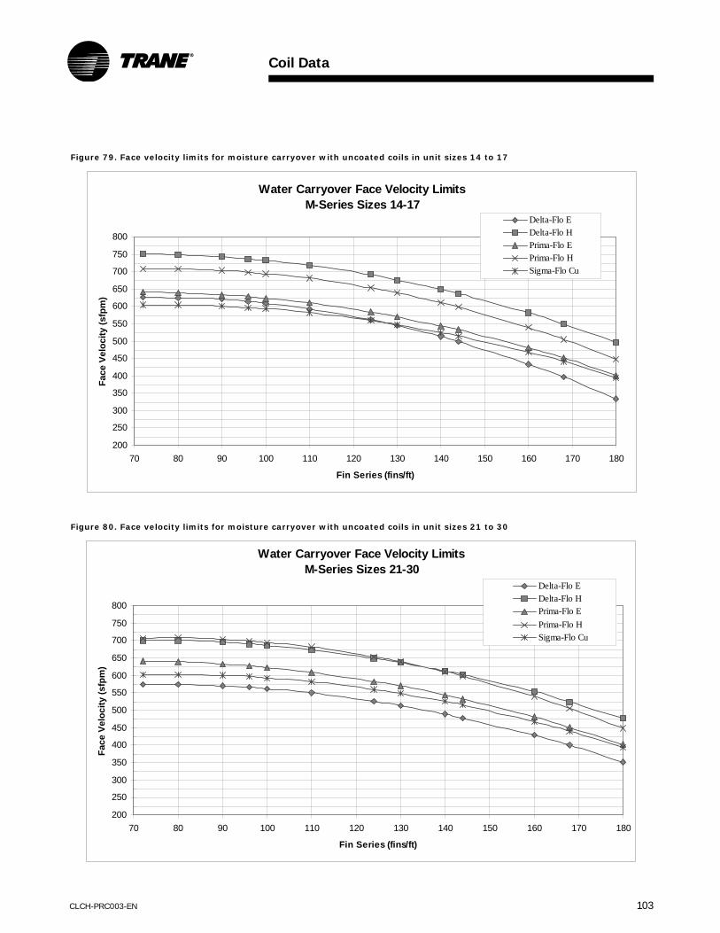
Coil Data
CLCH-PRC003-EN 103
Figure 79. Face velocity limits for moisture carryover with uncoated coils in unit sizes 14 to 17
Figure 80. Face velocity limits for moisture carryover with uncoated coils in unit sizes 21 to 30
Water Carryover Face Velocity LimitsM-Series Sizes 14-17
200
250
300
350
400
450
500
550
600
650
700
750
800
70 80 90 100 110 120 130 140 150 160 170 180
Fin Series (fins/ft)
Face
Vel
ocity
(sfp
m)
Delta-Flo EDelta-Flo HPrima-Flo EPrima-Flo HSigma-Flo Cu
Water Carryover Face Velocity LimitsM-Series Sizes 21-30
200
250
300
350
400
450
500
550
600
650
700
750
800
70 80 90 100 110 120 130 140 150 160 170 180
Fin Series (fins/ft)
Face
Vel
ocity
(sfp
m)
Delta-Flo EDelta-Flo HPrima-Flo EPrima-Flo HSigma-Flo Cu
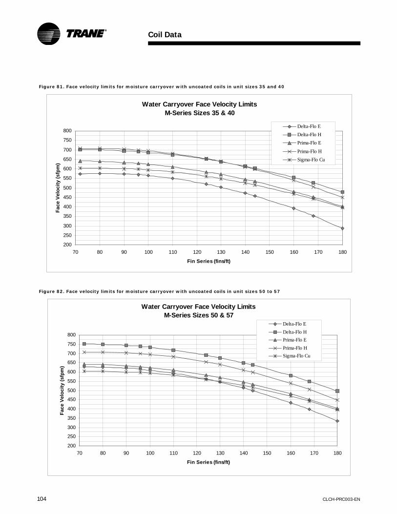
Coil Data
104 CLCH-PRC003-EN
Figure 81. Face velocity limits for moisture carryover with uncoated coils in unit sizes 35 and 40
Figure 82. Face velocity limits for moisture carryover with uncoated coils in unit sizes 50 to 57
Water Carryover Face Velocity LimitsM-Series Sizes 35 & 40
200
250
300
350
400
450
500
550
600
650
700
750
800
70 80 90 100 110 120 130 140 150 160 170 180
Fin Series (fins/ft)
Face
Vel
ocity
(sfp
m)
Delta-Flo EDelta-Flo HPrima-Flo E
Prima-Flo HSigma-Flo Cu
Water Carryover Face Velocity LimitsM-Series Sizes 50 & 57
200
250
300
350
400
450
500
550
600
650
700
750
800
70 80 90 100 110 120 130 140 150 160 170 180
Fin Series (fins/ft)
Face
Vel
ocity
(sfp
m)
Delta-Flo EDelta-Flo HPrima-Flo EPrima-Flo HSigma-Flo Cu

Coil Data
CLCH-PRC003-EN 105
Figure 83. Face velocity limits for moisture carryover with uncoated coils in unit size 66
Figure 84. Face velocity limits for moisture carryover with uncoated coils in unit sizes 80 to 120
Water Carryover Face Velocity LimitsM-Series Size 66
200
250
300
350
400
450
500
550
600
650
700
750
800
70 80 90 100 110 120 130 140 150 160 170 180
Fin Series (fins/ft)
Face
Vel
ocity
(sfp
m)
Delta-Flo EDelta-Flo HPrima-Flo EPrima-Flo HSigma-Flo Cu
Water Carryover Face Velocity LimitsM-Series Sizes 80-120
200
250
300
350
400
450
500
550
600
650
700
750
800
70 80 90 100 110 120 130 140 150 160 170 180
Fin Series (fins/ft)
Face
Vel
ocity
(sfp
m)
Delta-Flo EDelta-Flo HPrima-Flo E Prima-Flo HSigma-Flo Cu
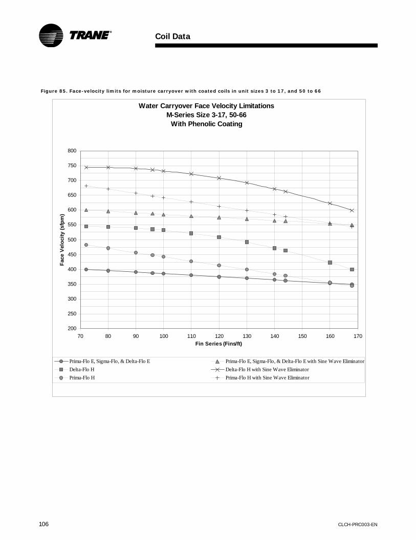
Coil Data
106 CLCH-PRC003-EN
Figure 85. Face-velocity limits for moisture carryover with coated coils in unit sizes 3 to 17, and 50 to 66
Water Carryover Face Velocity LimitationsM-Series Size 3-17, 50-66
With Phenolic Coating
200
250
300
350
400
450
500
550
600
650
700
750
800
70 80 90 100 110 120 130 140 150 160 170Fin Series (Fins/ft)
Face
Vel
ocity
(sfp
m)
Prima-Flo E, Sigma-Flo, & Delta-Flo E Prima-Flo E, Sigma-Flo, & Delta-Flo E with Sine Wave EliminatorDelta-Flo H Delta-Flo H with Sine Wave EliminatorPrima-Flo H Prima-Flo H with Sine Wave Eliminator

Coil Data
CLCH-PRC003-EN 107
Figure 86. Face-velocity limits for moisture carryover with coated coils in unit sizes 21-40, 80-120
W ater Carryover Face Velocity LimitationsM-Series Size 21-40, 80-120
W ith Phenolic Coating
200
250
300
350
400
450
500
550
600
650
700
750
800
70 80 90 100 110 120 130 140 150 160 170
Fin Series (Fins/ft)
Face
Vel
ocity
(ft/m
in)
Prima-Flo E, Sigma-Flo, & Delta-Flo E Prima-Flo E, Sigma-Flo, & Delta-Flo E with Sine W ave Eliminator
Delta-Flo H Delta-Flo H with Sine W ave Eliminator
Prima-Flo H Prima-Flo H with Sine W ave Eliminator

108 CLCH-PRC003-EN
Notes

CLCH-PRC003-EN 109
ModulePerformance Data
Accessories
Table 157. Accessories performance data
Accessory Unit SizePressure Drop (inches wg.) by Unit Coil Face Velocity (fpm)
400 450 500 550 600 650 700 750 800Moisture Eliminator All 0.02 0.02 0.03 0.04 0.06 0.08 0.10 0.13 0.16Humidifier All 0.02 0.02 0.03 0.03 0.04 0.05 0.05 0.06 0.07Intake Module All 0.05 0.06 0.09 0.11 0.12 0.13 0.16 0.18 0.21
Diffuser3-8 0.13 0.17 0.21 0.26 0.32 0.38 0.44 0.52 0.60
10-30 0.21 0.26 0.32 0.39 0.46 0.54 0.63 0.72 0.8235-120 0.53 0.67 0.83 1.00 1.19 1.40 1.62 1.86 2.12
Blender Module
Table 158. Blender module performance dataUnit Size
Area (sq.ft)
Pressure Drop (inches wg) by Blender Face Velocity (fpm)1000 1100 1200 1300 1400 1500 1600 1700 1800 1900 2000 2100 2200
3 1.50 0.15 0.18 0.21 0.25 0.29 0.30 0.38 0.43 0.48 0.53 0.59 0.65 0.716 2.80 0.14 0.16 0.19 0.23 0.26 0.30 0.35 0.39 0.44 0.49 0.54 0.60 0.658 3.30 0.15 0.18 0.12 0.25 0.28 0.33 0.37 0.42 0.47 0.52 0.58 0.64 0.7010 4.50 0.14 0.17 0.20 0.24 0.27 0.31 0.36 0.40 0.45 0.50 0.56 0.61 0.6712 5.20 0.15 0.18 0.21 0.25 0.29 0.33 0.38 0.42 0.48 0.53 0.59 0.65 0.7114 5.90 0.13 0.16 0.19 0.22 0.26 0.29 0.34 0.38 0.42 0.47 0.52 0.58 0.6317 6.60 0.13 0.16 0.19 0.22 0.26 0.29 0.33 0.38 0.42 0.47 0.52 0.57 0.6321 9.00 0.13 0.16 0.19 0.22 0.26 0.29 0.33 0.38 0.42 0.47 0.52 0.57 0.6325 10.40 0.14 0.17 0.21 0.24 0.28 0.32 0.37 0.41 0.47 0.52 0.57 0.63 0.6930 11.80 0.13 0.16 0.19 0.22 0.26 0.29 0.34 0.38 0.42 0.47 0.52 0.58 0.6335 13.40 0.13 0.16 0.19 0.22 0.25 0.29 0.33 0.38 0.42 0.47 0.52 0.57 0.6340 17.70 0.13 0.16 0.19 0.22 0.26 0.29 0.33 0.38 0.42 0.47 0.52 0.57 0.6350 20.10 0.14 0.16 0.19 0.23 0.26 0.30 0.35 0.39 0.44 0.49 0.54 0.60 0.6557 22.50 0.15 0.18 0.22 0.25 0.29 0.34 0.38 0.43 0.49 0.54 0.60 0.66 0.7366 27.60 0.12 0.15 0.18 0.21 0.24 0.28 0.32 0.36 0.40 0.44 0.49 0.54 0.6080 33.30 0.14 0.17 0.20 0.23 0.27 0.31 0.35 0.40 0.45 0.50 0.55 0.61 0.67100 39.75 0.14 0.17 0.21 0.24 0.28 0.32 0.37 0.41 0.46 0.52 0.57 0.63 0.69120 46.80 0.14 0.18 0.21 0.24 0.28 0.33 0.37 0.42 0.47 0.52 0.58 0.64 0.70

Module Performance Data
110 CLCH-PRC003-EN
Dampers
Energy Wheel Bypass Damper
Table 159. Energy wheel bypass damper
Unit SizeWheel Size
Static Pressure Drop (inches wg) by Damper Face Velocity (fpm)400 500 600 700 800 900 1000 1100 1200 1400 1600
3 900 0.04 0.07 0.09 0.13 0.17 0.21 0.26 0.32 0.38 0.51 0.673 1500 0.04 0.07 0.09 0.13 0.17 0.21 0.26 0.32 0.38 0.51 0.676 900 0.04 0.07 0.09 0.13 0.17 0.21 0.26 0.32 0.38 0.51 0.676 1500 0.04 0.07 0.09 0.13 0.17 0.21 0.26 0.32 0.38 0.51 0.676 3000 0.04 0.06 0.08 0.11 0.15 0.19 0.23 0.28 0.33 0.45 0.598 1500 0.04 0.07 0.09 0.13 0.17 0.21 0.26 0.32 0.38 0.51 0.678 3000 0.04 0.06 0.08 0.11 0.15 0.19 0.23 0.28 0.33 0.45 0.598 4000 0.04 0.06 0.08 0.11 0.14 0.18 0.22 0.27 0.32 0.43 0.5710 1500 0.04 0.07 0.09 0.13 0.17 0.21 0.26 0.32 0.38 0.51 0.6710 3000 0.04 0.06 0.08 0.11 0.15 0.19 0.23 0.28 0.33 0.45 0.5910 4000 0.04 0.06 0.08 0.11 0.14 0.18 0.22 0.27 0.32 0.43 0.5710 5000 0.03 0.05 0.08 0.11 0.14 0.17 0.22 0.26 0.31 0.42 0.5512 1500 0.04 0.07 0.09 0.13 0.17 0.21 0.26 0.32 0.38 0.51 0.6712 3000 0.04 0.06 0.08 0.11 0.15 0.19 0.23 0.28 0.33 0.45 0.5912 4000 0.04 0.06 0.08 0.11 0.14 0.18 0.22 0.27 0.32 0.43 0.5712 5000 0.03 0.05 0.08 0.11 0.14 0.17 0.22 0.26 0.31 0.42 0.5512 6000 0.03 0.05 0.08 0.10 0.14 0.17 0.21 0.26 0.31 0.42 0.5414 1500 0.04 0.07 0.09 0.13 0.17 0.21 0.26 0.32 0.38 0.51 0.6714 3000 0.04 0.06 0.08 0.11 0.15 0.19 0.23 0.28 0.33 0.45 0.5914 4000 0.04 0.06 0.08 0.11 0.14 0.18 0.22 0.27 0.32 0.43 0.5714 5000 0.03 0.05 0.08 0.11 0.14 0.17 0.22 0.26 0.31 0.42 0.5514 6000 0.03 0.05 0.08 0.10 0.14 0.17 0.21 0.26 0.31 0.42 0.5414 7000 0.04 0.06 0.08 0.11 0.15 0.19 0.23 0.28 0.33 0.45 0.5817 3000 0.04 0.06 0.08 0.11 0.15 0.19 0.23 0.28 0.33 0.45 0.5917 4000 0.04 0.06 0.08 0.11 0.14 0.18 0.22 0.27 0.32 0.43 0.5717 5000 0.03 0.05 0.08 0.11 0.14 0.17 0.22 0.26 0.31 0.42 0.5517 6000 0.03 0.05 0.08 0.10 0.14 0.17 0.21 0.26 0.31 0.42 0.5417 7000 0.04 0.06 0.08 0.11 0.15 0.19 0.23 0.28 0.33 0.45 0.5817 8500 0.04 0.06 0.08 0.11 0.14 0.18 0.23 0.27 0.32 0.44 0.5821 3000 0.04 0.06 0.08 0.11 0.15 0.19 0.23 0.28 0.33 0.45 0.5921 4000 0.04 0.06 0.08 0.11 0.14 0.18 0.22 0.27 0.32 0.43 0.5721 5000 0.03 0.05 0.08 0.11 0.14 0.17 0.22 0.26 0.31 0.42 0.5521 6000 0.03 0.05 0.08 0.10 0.14 0.17 0.21 0.26 0.31 0.42 0.5421 7000 0.04 0.06 0.08 0.11 0.15 0.19 0.23 0.28 0.33 0.45 0.5821 8500 0.04 0.06 0.08 0.11 0.14 0.18 0.23 0.27 0.32 0.44 0.5821 10500 0.02 0.04 0.05 0.07 0.10 0.12 0.15 0.18 0.21 0.29 0.38

Module Performance Data
CLCH-PRC003-EN 111
Table 159. (continued) Energy wheel bypass damper
Unit SizeWheel Size
Static Pressure Drop (inches wg) by Damper Face Velocity (fpm)400 500 600 700 800 900 1000 1100 1200 1400 1600
25 4000 0.04 0.06 0.08 0.11 0.14 0.18 0.22 0.27 0.32 0.43 0.5725 5000 0.03 0.05 0.08 0.11 0.14 0.17 0.22 0.26 0.31 0.42 0.5525 6000 0.03 0.05 0.08 0.10 0.14 0.17 0.21 0.26 0.31 0.42 0.5425 7000 0.04 0.06 0.08 0.11 0.15 0.19 0.23 0.28 0.33 0.45 0.5825 8500 0.04 0.06 0.08 0.11 0.14 0.18 0.23 0.27 0.32 0.44 0.5825 10500 0.02 0.04 0.05 0.07 0.10 0.12 0.15 0.18 0.21 0.29 0.3825 12500 0.03 0.04 0.06 0.08 0.10 0.13 0.16 0.19 0.23 0.31 0.4130 4000 0.04 0.06 0.08 0.11 0.14 0.18 0.22 0.27 0.32 0.43 0.5730 5000 0.03 0.05 0.08 0.11 0.14 0.17 0.22 0.26 0.31 0.42 0.5530 6000 0.03 0.05 0.08 0.10 0.14 0.17 0.21 0.26 0.31 0.42 0.5430 7000 0.04 0.06 0.08 0.11 0.15 0.19 0.23 0.28 0.33 0.45 0.5830 8500 0.04 0.06 0.08 0.11 0.14 0.18 0.23 0.27 0.32 0.44 0.5830 10500 0.02 0.04 0.05 0.07 0.10 0.12 0.15 0.18 0.21 0.29 0.3830 12500 0.03 0.04 0.06 0.08 0.10 0.13 0.16 0.19 0.23 0.31 0.4130 15000 0.02 0.04 0.06 0.08 0.10 0.13 0.16 0.19 0.22 0.30 0.4035 5000 0.03 0.05 0.08 0.11 0.14 0.17 0.22 0.26 0.31 0.42 0.5535 6000 0.03 0.05 0.08 0.10 0.14 0.17 0.21 0.26 0.31 0.42 0.5435 7000 0.04 0.06 0.08 0.11 0.15 0.19 0.23 0.28 0.33 0.45 0.5835 8500 0.04 0.06 0.08 0.11 0.14 0.18 0.23 0.27 0.32 0.44 0.5835 10500 0.02 0.04 0.05 0.07 0.10 0.12 0.15 0.18 0.21 0.29 0.3835 12500 0.03 0.04 0.06 0.08 0.10 0.13 0.16 0.19 0.23 0.31 0.4135 15000 0.02 0.04 0.06 0.08 0.10 0.13 0.16 0.19 0.22 0.30 0.4035 17500 0.02 0.04 0.05 0.07 0.10 0.12 0.15 0.18 0.22 0.30 0.3940 5000 0.03 0.05 0.08 0.11 0.14 0.17 0.22 0.26 0.31 0.42 0.5540 6000 0.03 0.05 0.08 0.10 0.14 0.17 0.21 0.26 0.31 0.42 0.5440 7000 0.04 0.06 0.08 0.11 0.15 0.19 0.23 0.28 0.33 0.45 0.5840 8500 0.04 0.06 0.08 0.11 0.14 0.18 0.23 0.27 0.32 0.44 0.5840 10500 0.02 0.04 0.05 0.07 0.10 0.12 0.15 0.18 0.21 0.29 0.3840 12500 0.03 0.04 0.06 0.08 0.10 0.13 0.16 0.19 0.23 0.31 0.4140 15000 0.02 0.04 0.06 0.08 0.10 0.13 0.16 0.19 0.22 0.30 0.4040 17500 0.02 0.04 0.05 0.07 0.10 0.12 0.15 0.18 0.22 0.30 0.3940 20000 0.02 0.04 0.05 0.07 0.10 0.12 0.15 0.18 0.22 0.29 0.3850 7000 0.04 0.06 0.08 0.11 0.15 0.19 0.23 0.28 0.33 0.45 0.5850 8500 0.04 0.06 0.08 0.11 0.14 0.18 0.23 0.27 0.32 0.44 0.5850 10500 0.02 0.04 0.05 0.07 0.10 0.12 0.15 0.18 0.21 0.29 0.3850 12500 0.03 0.04 0.06 0.08 0.10 0.13 0.16 0.19 0.23 0.31 0.4150 15000 0.02 0.04 0.06 0.08 0.10 0.13 0.16 0.19 0.22 0.30 0.4050 17500 0.02 0.04 0.05 0.07 0.10 0.12 0.15 0.18 0.22 0.30 0.3950 20000 0.02 0.04 0.05 0.07 0.10 0.12 0.15 0.18 0.22 0.29 0.3850 25000 0.02 0.04 0.05 0.07 0.09 0.12 0.15 0.18 0.21 0.29 0.38
Energy Wheel Return DamperTable 160. Energy wheel return damper
Unit SizeStatic Pressure Drop (inches wg) by Damper Face Velocity (fpm)
400 500 600 700 800 900 1000 1100 1200 1400 16003 0.04 0.06 0.09 0.12 0.16 0.20 0.25 0.30 0.36 0.48 0.636 0.04 0.06 0.08 0.11 0.15 0.18 0.23 0.27 0.33 0.45 0.588 0.04 0.06 0.08 0.11 0.14 0.18 0.22 0.27 0.32 0.44 0.5710 0.03 0.05 0.08 0.11 0.14 0.18 0.22 0.26 0.31 0.43 0.5612 0.03 0.05 0.08 0.11 0.14 0.17 0.22 0.26 0.31 0.42 0.5514 0.03 0.05 0.08 0.11 0.14 0.17 0.21 0.26 0.31 0.42 0.5517 0.04 0.06 0.08 0.11 0.15 0.19 0.23 0.28 0.33 0.45 0.5921 0.04 0.06 0.08 0.11 0.15 0.19 0.23 0.28 0.33 0.45 0.5925 0.04 0.06 0.08 0.11 0.15 0.18 0.23 0.28 0.33 0.45 0.5830 0.04 0.06 0.08 0.11 0.14 0.18 0.22 0.27 0.32 0.44 0.5735 0.04 0.06 0.08 0.11 0.14 0.18 0.22 0.27 0.32 0.43 0.5740 0.03 0.05 0.08 0.11 0.14 0.18 0.22 0.26 0.31 0.43 0.5650 0.03 0.05 0.08 0.11 0.14 0.17 0.22 0.26 0.31 0.42 0.55
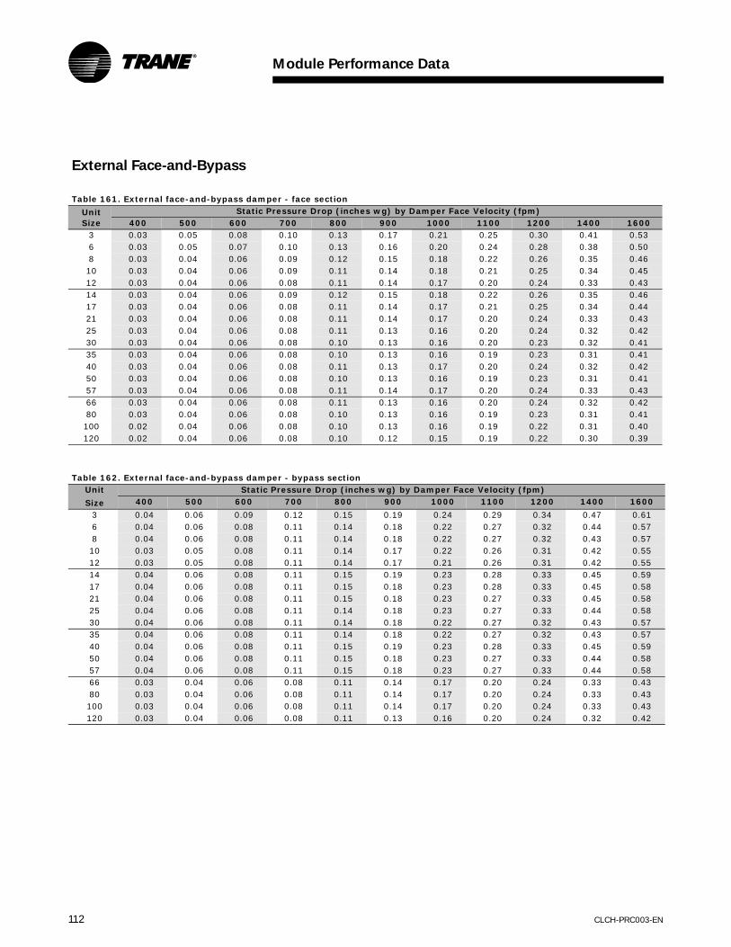
Module Performance Data
112 CLCH-PRC003-EN
External Face-and-Bypass
Table 161. External face-and-bypass damper - face section
Unit Size
Static Pressure Drop (inches wg) by Damper Face Velocity (fpm)400 500 600 700 800 900 1000 1100 1200 1400 1600
3 0.03 0.05 0.08 0.10 0.13 0.17 0.21 0.25 0.30 0.41 0.536 0.03 0.05 0.07 0.10 0.13 0.16 0.20 0.24 0.28 0.38 0.508 0.03 0.04 0.06 0.09 0.12 0.15 0.18 0.22 0.26 0.35 0.4610 0.03 0.04 0.06 0.09 0.11 0.14 0.18 0.21 0.25 0.34 0.4512 0.03 0.04 0.06 0.08 0.11 0.14 0.17 0.20 0.24 0.33 0.4314 0.03 0.04 0.06 0.09 0.12 0.15 0.18 0.22 0.26 0.35 0.4617 0.03 0.04 0.06 0.08 0.11 0.14 0.17 0.21 0.25 0.34 0.4421 0.03 0.04 0.06 0.08 0.11 0.14 0.17 0.20 0.24 0.33 0.4325 0.03 0.04 0.06 0.08 0.11 0.13 0.16 0.20 0.24 0.32 0.4230 0.03 0.04 0.06 0.08 0.10 0.13 0.16 0.20 0.23 0.32 0.4135 0.03 0.04 0.06 0.08 0.10 0.13 0.16 0.19 0.23 0.31 0.4140 0.03 0.04 0.06 0.08 0.11 0.13 0.17 0.20 0.24 0.32 0.4250 0.03 0.04 0.06 0.08 0.10 0.13 0.16 0.19 0.23 0.31 0.4157 0.03 0.04 0.06 0.08 0.11 0.14 0.17 0.20 0.24 0.33 0.4366 0.03 0.04 0.06 0.08 0.11 0.13 0.16 0.20 0.24 0.32 0.4280 0.03 0.04 0.06 0.08 0.10 0.13 0.16 0.19 0.23 0.31 0.41100 0.02 0.04 0.06 0.08 0.10 0.13 0.16 0.19 0.22 0.31 0.40120 0.02 0.04 0.06 0.08 0.10 0.12 0.15 0.19 0.22 0.30 0.39
Table 162. External face-and-bypass damper - bypass sectionUnit
Size
Static Pressure Drop (inches wg) by Damper Face Velocity (fpm)400 500 600 700 800 900 1000 1100 1200 1400 1600
3 0.04 0.06 0.09 0.12 0.15 0.19 0.24 0.29 0.34 0.47 0.616 0.04 0.06 0.08 0.11 0.14 0.18 0.22 0.27 0.32 0.44 0.578 0.04 0.06 0.08 0.11 0.14 0.18 0.22 0.27 0.32 0.43 0.5710 0.03 0.05 0.08 0.11 0.14 0.17 0.22 0.26 0.31 0.42 0.5512 0.03 0.05 0.08 0.11 0.14 0.17 0.21 0.26 0.31 0.42 0.5514 0.04 0.06 0.08 0.11 0.15 0.19 0.23 0.28 0.33 0.45 0.5917 0.04 0.06 0.08 0.11 0.15 0.18 0.23 0.28 0.33 0.45 0.5821 0.04 0.06 0.08 0.11 0.15 0.18 0.23 0.27 0.33 0.45 0.5825 0.04 0.06 0.08 0.11 0.14 0.18 0.23 0.27 0.33 0.44 0.5830 0.04 0.06 0.08 0.11 0.14 0.18 0.22 0.27 0.32 0.43 0.5735 0.04 0.06 0.08 0.11 0.14 0.18 0.22 0.27 0.32 0.43 0.5740 0.04 0.06 0.08 0.11 0.15 0.19 0.23 0.28 0.33 0.45 0.5950 0.04 0.06 0.08 0.11 0.15 0.18 0.23 0.27 0.33 0.44 0.5857 0.04 0.06 0.08 0.11 0.15 0.18 0.23 0.27 0.33 0.44 0.5866 0.03 0.04 0.06 0.08 0.11 0.14 0.17 0.20 0.24 0.33 0.4380 0.03 0.04 0.06 0.08 0.11 0.14 0.17 0.20 0.24 0.33 0.43100 0.03 0.04 0.06 0.08 0.11 0.14 0.17 0.20 0.24 0.33 0.43120 0.03 0.04 0.06 0.08 0.11 0.13 0.16 0.20 0.24 0.32 0.42

Module Performance Data
CLCH-PRC003-EN 113
Internal Face-and-Bypass
Table 163. Internal face-and-bypass damper - face section
Unit SizeStatic Pressure Drop (inches wg) by Damper Face Velocity (fpm)
400 500 600 700 800 900 1000 1100 1200 1400 16003 0.04 0.06 0.09 0.12 0.15 0.20 0.24 0.29 0.35 0.47 0.626 0.03 0.05 0.07 0.10 0.13 0.16 0.20 0.24 0.28 0.38 0.508 0.03 0.04 0.06 0.09 0.11 0.14 0.18 0.21 0.25 0.35 0.4510 0.03 0.05 0.07 0.09 0.12 0.15 0.19 0.23 0.27 0.37 0.4812 0.03 0.04 0.06 0.08 0.10 0.13 0.16 0.20 0.24 0.32 0.4214 0.03 0.05 0.07 0.09 0.12 0.15 0.19 0.23 0.27 0.37 0.4817 0.03 0.05 0.07 0.09 0.12 0.15 0.19 0.22 0.27 0.36 0.4721 0.03 0.04 0.06 0.09 0.11 0.14 0.18 0.21 0.25 0.35 0.4525 0.03 0.04 0.06 0.08 0.11 0.14 0.17 0.21 0.25 0.33 0.4430 0.03 0.04 0.06 0.08 0.11 0.14 0.17 0.20 0.24 0.33 0.4335 0.03 0.04 0.06 0.08 0.11 0.14 0.17 0.20 0.24 0.33 0.4340 0.03 0.04 0.06 0.09 0.11 0.14 0.17 0.21 0.25 0.34 0.4550 0.03 0.04 0.06 0.08 0.11 0.13 0.16 0.20 0.24 0.32 0.4257 0.03 0.04 0.06 0.08 0.10 0.13 0.16 0.20 0.23 0.32 0.4166 0.03 0.04 0.06 0.08 0.10 0.13 0.16 0.19 0.23 0.31 0.4180 0.02 0.04 0.06 0.08 0.10 0.13 0.16 0.19 0.22 0.31 0.40100 0.02 0.04 0.05 0.07 0.10 0.12 0.15 0.18 0.22 0.30 0.39120 0.02 0.04 0.05 0.07 0.10 0.12 0.15 0.18 0.22 0.29 0.38
Table 164. Internal face-and-bypass damper - bypass section
Unit SizeStatic Pressure Drop (inches wg) by Damper Face Velocity (fpm)
400 500 600 700 800 900 1000 1100 1200 1400 16003 0.06 0.09 0.12 0.17 0.22 0.28 0.35 0.42 0.50 0.68 0.886 0.05 0.08 0.12 0.16 0.21 0.26 0.32 0.39 0.47 0.64 0.838 0.05 0.08 0.12 0.16 0.20 0.26 0.32 0.39 0.46 0.63 0.8210 0.05 0.08 0.11 0.15 0.20 0.25 0.31 0.38 0.45 0.61 0.8012 0.05 0.08 0.11 0.15 0.20 0.25 0.31 0.38 0.45 0.61 0.8014 0.05 0.08 0.12 0.16 0.21 0.27 0.33 0.40 0.48 0.66 0.8617 0.05 0.08 0.12 0.16 0.21 0.27 0.33 0.40 0.47 0.65 0.8421 0.04 0.06 0.08 0.11 0.15 0.18 0.23 0.27 0.33 0.45 0.5825 0.04 0.06 0.08 0.11 0.14 0.18 0.23 0.27 0.33 0.44 0.5830 0.04 0.06 0.08 0.11 0.14 0.18 0.22 0.27 0.32 0.43 0.5735 0.03 0.05 0.07 0.09 0.12 0.16 0.19 0.23 0.28 0.38 0.4940 0.03 0.05 0.07 0.10 0.13 0.16 0.20 0.24 0.29 0.39 0.5150 0.03 0.05 0.07 0.10 0.13 0.16 0.20 0.24 0.28 0.39 0.5157 0.03 0.05 0.07 0.10 0.13 0.16 0.20 0.24 0.28 0.39 0.5166 0.03 0.05 0.07 0.10 0.12 0.16 0.19 0.23 0.28 0.38 0.5080 0.03 0.05 0.07 0.10 0.12 0.16 0.19 0.23 0.28 0.38 0.50100 0.03 0.05 0.07 0.09 0.12 0.16 0.19 0.23 0.28 0.38 0.49120 0.03 0.05 0.07 0.09 0.12 0.15 0.19 0.23 0.27 0.37 0.48

Module Performance Data
114 CLCH-PRC003-EN
Full-Face Damper
Table 165. Full-face damper
Unit SizeStatic Pressure Drop (inches wg) by Damper Face Velocity (fpm)
400 500 600 700 800 900 1000 1100 1200 1400 16003 0.03 0.05 0.08 0.10 0.13 0.17 0.21 0.25 0.30 0.41 0.536 0.03 0.05 0.07 0.10 0.13 0.16 0.20 0.24 0.28 0.38 0.508 0.03 0.04 0.06 0.09 0.12 0.15 0.18 0.22 0.26 0.35 0.4610 0.03 0.04 0.06 0.09 0.11 0.14 0.18 0.21 0.25 0.34 0.4512 0.03 0.04 0.06 0.08 0.11 0.14 0.17 0.20 0.24 0.33 0.4314 0.03 0.04 0.06 0.09 0.12 0.15 0.18 0.22 0.26 0.35 0.4617 0.03 0.04 0.06 0.08 0.11 0.14 0.17 0.21 0.25 0.34 0.4421 0.03 0.04 0.06 0.08 0.11 0.14 0.17 0.20 0.24 0.33 0.4325 0.03 0.04 0.06 0.08 0.11 0.13 0.16 0.20 0.24 0.32 0.4230 0.03 0.04 0.06 0.08 0.10 0.13 0.16 0.20 0.23 0.32 0.4135 0.03 0.04 0.06 0.08 0.10 0.13 0.16 0.19 0.23 0.31 0.4140 0.03 0.04 0.06 0.08 0.11 0.13 0.17 0.20 0.24 0.32 0.4250 0.03 0.04 0.06 0.08 0.10 0.13 0.16 0.19 0.23 0.31 0.4157 0.03 0.04 0.06 0.08 0.11 0.14 0.17 0.20 0.24 0.33 0.4366 0.03 0.04 0.06 0.08 0.11 0.13 0.16 0.20 0.24 0.32 0.4280 0.03 0.04 0.06 0.08 0.10 0.13 0.16 0.19 0.23 0.31 0.41100 0.02 0.04 0.06 0.08 0.10 0.13 0.16 0.19 0.22 0.31 0.40120 0.02 0.04 0.06 0.08 0.10 0.12 0.15 0.19 0.22 0.30 0.39

Module Performance Data
CLCH-PRC003-EN 115
Baffles
Selection Procedure
Use this procedure to balance hot-deck and cold-deck airflows:
1 Determine face velocity of hot-deck and cold-deck coils.
2 Determine air pressure drop (APD) for each coil.
3 Determine hot-deck casing loss using the formula below.
Note: Vcoil is cooling coil face velocity.
Multizone
Table 166. Multizone damper -2 deck with hot and cold coil
Unit SizeStatic Pressure Drop (inches wg) by Damper Face Velocity (fpm)
400 500 600 700 800 900 1000 1100 1200 14006 0.03 0.05 0.08 0.11 0.14 0.17 0.22 0.26 0.31 0.428 0.03 0.05 0.08 0.11 0.14 0.17 0.22 0.26 0.31 0.4210 0.03 0.05 0.07 0.09 0.12 0.16 0.19 0.23 0.28 0.3812 0.03 0.05 0.07 0.09 0.12 0.15 0.19 0.23 0.27 0.3714 0.03 0.05 0.07 0.09 0.12 0.15 0.19 0.23 0.27 0.3717 0.03 0.05 0.07 0.09 0.12 0.15 0.19 0.23 0.27 0.3721 0.03 0.04 0.06 0.09 0.11 0.14 0.18 0.21 0.25 0.3525 0.03 0.04 0.06 0.09 0.11 0.14 0.18 0.22 0.26 0.3530 0.03 0.04 0.06 0.09 0.11 0.14 0.18 0.21 0.25 0.3435 0.03 0.04 0.06 0.08 0.11 0.14 0.17 0.20 0.24 0.3340 0.03 0.04 0.06 0.08 0.11 0.13 0.17 0.20 0.24 0.3250 0.03 0.04 0.06 0.08 0.11 0.13 0.16 0.20 0.24 0.32
Hot-deck APD =
Table 167. Baffles
Baffle Selection
Static Pressure Drop (inches wg.) by Coil Face Velocity (fpm)400 450 500 550 600 650 700 750 800 850 900 1000 1200 1300 1400
No. 22 .37 .47 .57 .69 .83 .97 1.12 1.28 1.47 n/a n/a n/a n/a n/a n/aNo. 40 .10 .13 .17 .21 .25 .29 .34 .40 .45 .51 .57 .70 1.20 n/a n/aNo. 60 .06 .08 .10 .12 .15 .18 .21 .24 .26 .29 .33 .41 .59 .69 .80No. 70 .04 .05 .07 .08 .09 .10 .12 .14 .16 .18 .20 .25 .35 .42 .49
KtVcoil500
---------------⎝ ⎠⎛ ⎞2
•
Sizes 6 - 10Kt = 0.24
Sizes 12 - 17Kt = 0.36
Sizes 21 - 50Kt = 0.62
4 Determine total hot deck losses for 100 percent heating (total hot deck APD = casing + heating coil APD).
5 Determine the pressure differential between the decks. The deck with the lowest pressure drop may require baffles.
6 Use Table 167 below to choose a baffle or combination of baffles that will provide the static pressure drop necessary to compensate for the pressure differential determined in Step 5.

Module Performance Data
116 CLCH-PRC003-EN
Mixing Box with Dampers
Table 168. Mixing box with front, back, top and bottom airfoil blade dampers (unducted)
Unit SizeStatic Pressure Drop (inches wg) by Damper Face Velocity (fpm)
400 500 600 700 800 900 1000 1100 1200 1400 16003 0.04 0.07 0.09 0.13 0.17 0.21 0.26 0.32 0.38 0.51 0.676 0.04 0.06 0.08 0.11 0.15 0.19 0.23 0.28 0.33 0.45 0.598 0.04 0.06 0.08 0.11 0.15 0.18 0.23 0.28 0.33 0.45 0.5810 0.04 0.06 0.08 0.11 0.14 0.18 0.22 0.27 0.32 0.44 0.5712 0.03 0.05 0.08 0.11 0.14 0.18 0.22 0.26 0.31 0.43 0.5614 0.03 0.05 0.07 0.09 0.12 0.16 0.19 0.23 0.28 0.38 0.5017 0.03 0.05 0.07 0.09 0.12 0.15 0.19 0.23 0.27 0.37 0.4921 0.03 0.05 0.07 0.09 0.12 0.15 0.19 0.23 0.27 0.37 0.4825 0.03 0.04 0.06 0.09 0.11 0.14 0.17 0.21 0.25 0.34 0.4530 0.03 0.04 0.06 0.08 0.11 0.14 0.17 0.21 0.25 0.34 0.4435 0.03 0.04 0.06 0.08 0.11 0.13 0.17 0.20 0.24 0.32 0.4240 0.03 0.04 0.06 0.09 0.11 0.14 0.18 0.21 0.25 0.34 0.4550 0.03 0.04 0.06 0.08 0.11 0.14 0.17 0.21 0.25 0.33 0.4457 0.03 0.04 0.06 0.08 0.10 0.13 0.16 0.20 0.24 0.32 0.4266 0.03 0.04 0.06 0.08 0.10 0.13 0.16 0.20 0.24 0.32 0.4280 0.03 0.04 0.06 0.08 0.10 0.13 0.16 0.19 0.23 0.31 0.41100 0.02 0.04 0.06 0.08 0.10 0.13 0.16 0.19 0.22 0.31 0.40120 0.03 0.04 0.06 0.08 0.10 0.13 0.16 0.19 0.23 0.31 0.41
Table 169. Mixing box with side airfoil blade dampers (unducted)
Unit SizeStatic Pressure Drop (inches wg) by Damper Face Velocity (fpm)
400 500 600 700 800 900 1000 1100 1200 1400 16003 0.06 0.09 0.13 0.18 0.23 0.30 0.37 0.44 0.53 0.72 0.936 0.04 0.07 0.10 0.14 0.18 0.23 0.28 0.34 0.40 0.55 0.728 0.04 0.06 0.09 0.13 0.17 0.21 0.26 0.31 0.37 0.51 0.6610 0.04 0.06 0.08 0.11 0.15 0.19 0.23 0.28 0.33 0.45 0.5912 0.03 0.05 0.08 0.11 0.14 0.18 0.22 0.26 0.31 0.43 0.5614 0.03 0.05 0.08 0.10 0.13 0.17 0.21 0.25 0.30 0.41 0.5417 0.03 0.05 0.07 0.10 0.13 0.16 0.20 0.25 0.29 0.40 0.5221 0.03 0.05 0.07 0.10 0.13 0.16 0.20 0.24 0.29 0.39 0.5125 0.03 0.05 0.07 0.10 0.12 0.16 0.19 0.24 0.28 0.38 0.5030 0.03 0.05 0.07 0.10 0.13 0.17 0.21 0.25 0.30 0.40 0.5335 0.03 0.05 0.07 0.10 0.13 0.16 0.20 0.24 0.29 0.39 0.5140 0.03 0.05 0.07 0.09 0.12 0.16 0.19 0.23 0.28 0.38 0.4950 0.03 0.05 0.07 0.09 0.12 0.15 0.18 0.22 0.26 0.36 0.4757 0.03 0.04 0.06 0.09 0.11 0.15 0.18 0.22 0.26 0.35 0.4666 0.03 0.04 0.06 0.09 0.11 0.14 0.17 0.21 0.25 0.34 0.4580 0.03 0.05 0.07 0.09 0.12 0.15 0.18 0.22 0.26 0.35 0.46100 0.03 0.04 0.06 0.09 0.11 0.14 0.17 0.21 0.25 0.34 0.45120 0.03 0.04 0.06 0.08 0.11 0.14 0.17 0.21 0.25 0.33 0.44

Module Performance Data
CLCH-PRC003-EN 117
Table 170. Mixing box with Traq™ dampersUnit Size
Static Pressure Drop (inches wg) by Damper Face Velocity (fpm)800 900 1000 1100 1200 1300 1400 1500 1600 1700 1800 1900 2000 2100 2200 2300
3 0.04 0.05 0.07 0.08 0.09 0.11 0.13 0.15 0.17 0.19 0.21 0.24 0.26 0.29 0.31 0.356 0.04 0.05 0.06 0.07 0.08 0.10 0.11 0.13 0.15 0.17 0.19 0.21 0.23 0.26 0.28 0.318 0.04 0.05 0.07 0.08 0.10 0.11 0.13 0.15 0.17 0.20 0.22 0.24 0.27 0.30 0.33 0.3610 0.04 0.05 0.07 0.08 0.09 0.11 0.13 0.15 0.17 0.19 0.21 0.24 0.26 0.29 0.32 0.3512 0.04 0.05 0.06 0.07 0.08 0.10 0.11 0.13 0.15 0.16 0.18 0.21 0.23 0.25 0.28 0.3014 0.04 0.05 0.06 0.07 0.09 0.10 0.12 0.14 0.16 0.18 0.20 0.22 0.25 0.27 0.30 0.3217 0.04 0.06 0.07 0.08 0.10 0.12 0.13 0.15 0.18 0.20 0.22 0.25 0.28 0.30 0.33 0.3521 0.04 0.05 0.06 0.07 0.08 0.10 0.12 0.13 0.15 0.17 0.19 0.21 0.24 0.26 0.29 0.3225 0.04 0.05 0.06 0.08 0.09 0.11 0.13 0.15 0.17 0.19 0.21 0.23 0.26 0.29 0.32 0.3530 0.04 0.04 0.06 0.07 0.08 0.09 0.11 0.12 0.14 0.16 0.18 0.20 0.22 0.24 0.26 0.2935 0.04 0.05 0.06 0.07 0.09 0.10 0.12 0.14 0.16 0.18 0.20 0.22 0.25 0.27 0.29 0.3240 0.04 0.05 0.07 0.08 0.10 0.11 0.13 0.15 0.17 0.19 0.22 0.24 0.27 0.29 0.31 0.3450 0.04 0.05 0.07 0.08 0.10 0.11 0.13 0.15 0.17 0.19 0.21 0.24 0.26 0.29 0.32 0.3557 0.04 0.05 0.07 0.08 0.10 0.11 0.13 0.15 0.17 0.19 0.21 0.24 0.26 0.29 0.32 0.3566 0.04 0.06 0.07 0.08 0.10 0.12 0.14 0.16 0.18 0.20 0.22 0.25 0.28 0.30 0.33 0.3680 0.04 0.05 0.07 0.08 0.10 0.11 0.13 0.15 0.17 0.19 0.22 0.24 0.27 0.29 0.32 0.35100 0.04 0.06 0.07 0.08 0.10 0.12 0.13 0.15 0.17 0.20 0.22 0.25 0.27 0.30 0.33 0.36120 0.04 0.06 0.07 0.08 0.10 0.12 0.13 0.15 0.17 0.20 0.22 0.24 0.27 0.29 0.33 0.36

Module Performance Data
118 CLCH-PRC003-EN
Damper Torque Requirements
Table 171. Damper torque requirements (inch pound) at 1-inch w.g. air pressure drop
Unit Size Face Damper Internal Face-
and-BypassExternal Face-
and-BypassIntegral Face-
and-BypassMultizone1
Top Discharge Front Discharge3 16 17 27 10 N/A N/A6 24 29 40 17 5 78 33 39 52 26 5 710 43 50 66 31 6 812 56 62 81 36 6 814 60 69 87 41 6 817 78 83 107 62 6 821 92 99 122 62 7 1025 108 115 139 86 7 1030 127 136 163 86 7 1035 143 154 180 103 17 2440 160 172 201 103 17 2450 215 228 261 161 17 2457 253 267 299 161 n/a n/a66 307 308 404 201 n/a n/a80 364 364 460 221 n/a n/a100 460 460 569 314 n/a n/a120 549 549 678 314 n/a n/a
Unit Size
Mixing Module Dampers (Top-Back-Bottom Locations) Side Locations
Traq damper only
Bladed damper only
Traq damper linked to bladed
damper
Bladed damper linked to bladed
damper
Traq damper linked to Traq
damper
Bladed damper only
3 18 12 20 14 36 106 36 21 39 24 72 178 36 24 39 27 72 2210 54 29 58 33 108 3012 68 36 73 41 135 3614 68 41 73 47 135 4317 68 49 74 56 135 4921 72 60 81 69 144 5825 72 72 82 82 144 6730 99 84 111 96 198 8735 108 100 122 114 216 10240 108 115 125 132 216 11750 113 146 159 167 225 14857 113 199 211 227 225 16966 150 199 216 227 300 20080 188 233 254 266 375 240100 225 292 318 334 450 296120 225 353 379 404 450 342
1 Torque is per blade. Multiply blades required per zone by torque value to size actuator per zone.

Module Performance Data
CLCH-PRC003-EN 119
Discharge Plenums
Front- or Top-Mounted
Discharge Plenum with
Factory Openings
Note: Top-mounted fan discharges indicate vertical airflow direction; front-mounted fan discharges indicate horizontal airflow direction.
Figure 87. Horizontal plenum
Table 172. Discharge plenums—factory outlet areas (ft²)
Unit SizeTop-mounted discharge Front-mounted discharge
Down discharge plenumFront, top, back,
bottom openingsSide openings
Top, bottom openings
Front openings Side openings
3 1.13 0.99 1.13 1.13 0.99 4.176 1.94 1.60 1.94 1.94 1.60 6.888 2.35 2.01 2.35 2.35 2.01 9.1710 3.07 2.66 3.07 3.07 2.66 11.6712 3.48 3.23 3.48 3.48 3.23 12.5014 3.55 3.80 3.55 3.55 3.80 13.3317 4.19 4.37 4.19 4.19 4.37 14.5821 5.19 5.08 5.19 5.19 5.08 15.0025 6.10 5.97 6.10 6.10 5.97 18.5030 7.24 7.65 7.24 7.24 7.65 21.7535 8.56 8.75 8.56 8.56 8.75 27.1740 9.84 8.75 9.84 9.84 10.02 31.0650 12.35 12.67 12.35 12.36 12.67 34.3457 12.35 12.67 14.26 14.65 14.43 34.3466 n/a n/a 22.00 17.25 16.42 40.3380 n/a n/a 26.20 20.58 19.74 44.92100 n/a n/a 33.61 25.30 25.49 56.15120 n/a n/a 39.72 28.58 30.17 66.46
Refer to the General Data section on page 53 for fan outlet areas.
Formulas
For all factory openings, except a full bottom opening in a horizontal plenum, use:
SP =
For a full bottom opening in a horizontal plenum, use:
SP =
KtOVF4005------------⎝ ⎠⎛ ⎞
2• 0.5
OVP4005------------⎝ ⎠⎛ ⎞
2•+
KtOVF4005------------⎝ ⎠⎛ ⎞•
2
Where:
SP = static pressure drop
Kt = value from Table 173, p. 120
OVF = FM/OAF
OVP = CFM/OAP
OVF = fan outlet velocity
OAF = fan outlet area
OVP = plenum opening outlet velocity
OAP = plenum opening area (see Table 173)
Figure 88. Vertical plenum

Module Performance Data
120 CLCH-PRC003-EN
Table 173. Discharge Plenums - factory openings, Kt values
Fan SizePlenum Discharge
Location
Plenum Location - Top Mounted Plenum Location - Horizontally MountedSupply Fan Discharge
Top-frontSupply Fan Discharge
Top-backSupply Fan Discharge
Front-topSupply Fan Discharge
Back-top
3-8 FC
Front-top 1.67 0.98 0.98 N/ABack-top 0.98 1.67 N/A 0.98
Top-front/back 0.98 0.98 1.67 1.67Side-top 1.50 1.50 1.50 1.50
Bottom-front/back or full bottom
N/A N/A 0.98 0.98
3-8 BC or AF
Front-top 1.14 0.68 0.68 N/ABack-top 0.68 1.14 N/A 0.68
Top-front/back 0.68 0.68 1.33 1.33Side-top 1.29 1.29 1.34 1.34
Bottom-front/back or full bottom
N/A N/A 0.78 0.78
10-17 FC
Front-top 2.59 1.68 1.68 N/ABack-top 1.68 2.59 N/A 1.68
Top-front/back 1.68 1.68 2.59 2.59Side-top 2.37 2.37 2.37 2.37
Bottom-front/back N/A N/A 1.68 1.68Full bottom N/A N/A 1.28 1.28
10-17 AF
Front-top 1.67 1.15 1.15 N/ABack-top 1.15 1.67 N/A 1.15
Top-front/back 1.15 1.15 1.83 1.83Side-top 1.85 1.85 1.85 1.85
Bottom-front/back or full bottom
N/A N/A 1.23 1.23
21-30 FC
Front-top 1.68 0.96 0.96 N/ABack-top 0.96 1.68 N/A 0.96
Top-front/back 0.96 0.96 1.68 1.68Side-top 1.50 1.50 1.50 1.50
Bottom-front/back or full bottom
N/A N/A 0.96 0.96
21-57 AF
Front-top 1.45 0.93 0.93 N/ABack-top 0.93 1.45 N/A 0.93
Top-front/back 0.93 0.93 1.81 1.81Side-top 1.68 1.68 1.68 1.68
Bottom-front/back or full bottom
N/A N/A 1.13 1.13
35-57 FC
Front-top 1.44 0.83 0.83 N/ABack-top 0.83 1.44 N/A 0.83
Top-front/back 0.83 0.83 1.44 1.44Side-top 1.25 1.25 1.25 1.25
Bottom-front/back N/A N/A 0.83 0.83Full bottom N/A N/A 0.73 0.73

Module Performance Data
CLCH-PRC003-EN 121
Table 173. (continued) Discharge plenums - factory openings, Kt values
Fan SizePlenum Discharge
Location
Plenum Location - Top Mounted Plenum Location - Horizontally MountedSupply Fan Discharge
Top-frontSupply Fan Discharge
Top-backSupply Fan Discharge
Front-topSupply Fan Discharge
Back-top
66-120 FC
Front-top N/A N/A 0.83 N/ABack-top N/A N/A N/A 0.83
Top-front/back N/A N/A 1.44 1.44Side-top N/A N/A 1.25 1.25
Bottom-front/back N/A N/A 0.83 0.83Full bottom N/A N/A 0.73 0.73
66-120 AF
Front-top N/A N/A 1.34 N/ABack-top N/A N/A N/A 1.34
Top-front/back N/A N/A 2.14 2.14Side-top N/A N/A 2.11 2.11
Bottom-front/back or full bottom
N/A N/A 1.34 1.34
12-17Q, 12-14R
Front-top n/a n/a 1.40 n/aBack-top n/a n/a n/a 1.40
Top-front/back n/a n/a 2.90 2.90Side-top n/a n/a 2.90 2.90
Bottom-front/back n/a n/a 2.90 2.90Full bottom n/a n/a 2.10 2.10
21-30Q, 17-25R
Front-top n/a n/a 1.40 n/aBack-top n/a n/a n/a 1.40
Top-front/back n/a n/a 2.90 2.90Side-top n/a n/a 2.90 2.90
Bottom-front/back n/a n/a 2.90 2.90Full bottom n/a n/a 2.00 2.00
35-80Q, 30-66R
Front-top n/a n/a 1.40 n/aBack-top n/a n/a n/a 1.40
Top-front/back n/a n/a 2.90 2.90Side-top n/a n/a 2.90 2.90
Bottom-front/back n/a n/a 2.90 2.90Full bottom n/a n/a 1.70 1.70
6 - 80 V, W
Front-top 2.20 2.20 n/a n/aBack-top 2.20 2.20 n/a n/a
Top-front/back 1.40 1.40 n/a n/aSide-top 2.20 2.20 n/a n/a
3 - 120 P
Front-top 2.50 2.50 2.50 n/aBack-top 2.50 2.50 n/a 2.50
Top-front/back 2.00 2.00 2.00 2.00Side-top 2.00 2.00 2.00 2.00
Bottom-front/back or full bottom
n/a n/a 2.00 2.00
AF = airfoil, FC = forward-curved, Q, R = vaneaxial

Module Performance Data
122 CLCH-PRC003-EN
Filters
Table 174. Filters - clean
Filter typeStatic Pressure Drop (inches wg) by Damper Face Velocity (fpm)
200 250 300 350 400 450 500 550 600Disposable 0.04 0.06 0.08 0.10 0.13 0.15 0.18 n/a n/a2-inch Pleated media 0.08 0.11 0.14 0.18 0.21 0.26 0.30 0.35 0.404-inch Pleated media 0.04 0.06 0.09 0.12 0.16 0.20 0.25 0.30 0.36Permanent 0.01 0.02 0.03 0.04 0.05 0.06 0.07 0.09 0.114-inch high efficiency-65% efficient 0.13 0.17 0.22 0.28 0.34 0.40 0.48 0.55 0.644-inch high efficiency - 85% efficient 0.21 0.28 0.36 0.45 0.55 0.66 0.77 0.90 1.034-inch high efficiency - 95% efficient 0.24 0.32 0.41 0.51 0.62 0.74 0.87 1.01 1.156-inch cartridge - 65% efficient 0.13 0.16 0.19 n/a n/a n/a n/a n/a n/a6-inch cartridge - 85% efficient 0.22 0.27 0.32 n/a n/a n/a n/a n/a n/a6-inch cartridge - 95% efficient 0.25 0.30 0.34 n/a n/a n/a n/a n/a n/a12-inch cartridge - 65% efficient 0.10 0.14 0.18 0.23 0.28 0.33 0.39 0.45 0.5212-inch cartridge - 85% efficient 0.17 0.23 0.29 0.36 0.43 0.51 0.59 0.68 0.7712-inch cartridge - 95% efficient 0.20 0.27 0.34 0.42 0.51 0.60 0.70 0.80 0.9118-inch bag - 65% efficient 0.18 0.22 0.27 0.31 0.35 0.39 0.44 0.48 0.5218-inch bag - 85% efficient 0.20 0.25 0.30 0.35 0.41 0.46 0.51 0.56 0.6118-inch bag - 95% efficient 0.23 0.28 0.34 0.39 0.45 0.50 0.56 0.61 0.6630-inch bag - 65% efficient 0.07 0.10 0.13 0.17 0.21 0.26 0.31 0.36 0.4230-inch bag - 85% efficient 0.09 0.11 0.15 0.18 0.22 0.26 0.31 0.35 0.4030-inch bag - 95% efficient 0.17 0.22 0.27 0.32 0.37 0.42 0.47 0.52 0.58HEPA 99.97 DOP 0.47 0.60 0.74 0.89 1.04 1.20 1.37 1.54 1.72
Table 175. Filters - dirty
Face Velocity (fpm) Static Pressure Drop (inches wg) by Damper Face Velocity (fpm)
200 250 300 350 400 450 500 550 600Disposable 1.00 1.00 1.00 1.00 1.00 1.00 1.00 n/a n/a2-inch Pleated media 1.00 1.00 1.00 1.00 1.00 1.00 1.00 1.00 1.004-inch Pleated media 1.00 1.00 1.00 1.00 1.00 1.00 1.00 1.00 1.00Permanent 1.00 1.00 1.00 1.00 1.00 1.00 1.00 1.00 1.004-inch high efficiency-65% efficient 1.20 1.20 1.20 1.20 1.20 1.20 1.20 1.20 1.204-inch high efficiency - 85% efficient 1.20 1.20 1.20 1.20 1.20 1.20 1.20 1.20 1.204-inch high efficiency - 95% efficient 1.20 1.20 1.20 1.20 1.20 1.20 1.20 1.20 1.206-inch cartridge - 65% efficient 1.20 1.20 1.20 n/a n/a n/a n/a n/a n/a6-inch cartridge - 85% efficient 1.20 1.20 1.20 n/a n/a n/a n/a n/a n/a6-inch cartridge - 95% efficient 1.20 1.20 1.20 n/a n/a n/a n/a n/a n/a12-inch cartridge - 65% efficient 1.20 1.20 1.20 1.20 1.20 1.20 1.20 1.20 1.2012-inch cartridge - 85% efficient 1.20 1.20 1.20 1.20 1.20 1.20 1.20 1.20 1.2012-inch cartridge - 95% efficient 1.20 1.20 1.20 1.20 1.20 1.20 1.20 1.20 1.2018-inch bag - 65% efficient 1.20 1.20 1.20 1.20 1.20 1.20 1.20 1.20 1.2018-inch bag - 85% efficient 1.20 1.20 1.20 1.20 1.20 1.20 1.20 1.20 1.2018-inch bag - 95% efficient 1.20 1.20 1.20 1.20 1.20 1.20 1.20 1.20 1.2030-inch bag - 65% efficient 1.20 1.20 1.20 1.20 1.20 1.20 1.20 1.20 1.2030-inch bag - 85% efficient 1.20 1.20 1.20 1.20 1.20 1.20 1.20 1.20 1.2030-inch bag - 95% efficient 1.20 1.20 1.20 1.20 1.20 1.20 1.20 1.20 1.20HEPA 99.97 DOP 2.00 2.00 2.00 2.00 2.00 2.00 2.00 2.00 2.00

Module Performance Data
CLCH-PRC003-EN 123
Fans
Gas Heat
Silencers
Table 176. Vertical Q fan pressure dropSize Inlet Screen6-80 0.10
Table 177. Q fan pressure dropSize Turning Module Downstream Inlet Screen Diffuser12Q, 14Q, 17Q, 12R, 14R 2.10 0.10 1.8021Q, 25Q, 30Q, 17R, 21R, 25R 2.00 0.10 1.8035Q, 40Q, 50Q, 57Q, 66Q, 80Q, 30R, 35R, 40R, 50R, 57R, 66R 1.70 0.10 1.80
Table 178. Gas heat
DischargeStatic Pressure Drop (inches wg) by Face Velocity (fpm)
500 750 1000 1250 1500 1750 2000 2250 2500 2750 3000Front/Bottom Discharge 0.51 0.52 0.53 0.55 0.57 0.60 0.62 0.66 0.69 0.74 0.78Full Face Front Discharge 0.50 0.50 0.50 0.50 0.50 0.50 0.50 0.50 0.50 0.50 0.50
Table 179. Silencers
Length Model Unit SizesSupplier Data Pressure Drop (inches wg)
250 500 750 1000 1250 1500 1750
3 Feet
RD-ULV-F2 10 0.03 0.11 0.26 0.45 0.71 1.02 1.39RD-ULV-F3 03, 40, 66, 80 0.03 0.11 0.25 0.45 0.70 1.01 1.37RD-ULV-F4 17, 21, 25, 100, 120 0.03 0.11 0.25 0.44 0.69 0.99 1.35RD-ULV-F5 08, 14, 30, 35, 50, 57 0.03 0.12 0.26 0.47 0.73 1.06 1.44RD-ULV-F6 06, 12 0.03 0.13 0.28 0.50 0.78 1.13 1.53
5 Feet
RD-ULV-F2 10 0.04 0.15 0.34 0.61 0.95 1.37 1.86RD-ULV-F3 03, 40, 66, 80 0.04 0.15 0.33 0.59 0.92 1.33 1.80RD-ULV-F4 17, 21, 25, 100, 120 0.04 0.14 0.32 0.57 0.89 1.28 1.75RD-ULV-F5 08, 14, 30, 35, 50, 57 0.04 0.15 0.34 0.60 0.94 1.36 1.85RD-ULV-F6 06, 12 0.04 0.16 0.36 0.64 0.99 1.43 1.95

124 CLCH-PRC003-EN
Dimensional Data by Module
Access Module
Figure 89. Access module
Table 180. Access module dimensions (inches)Unit Size
W H A BOutward
CInward
COutward
D1Inward
D1Outward
D2Inward
D2E E1 J K
ND (NPT)
3 31 26.25 27.00 22.25 21.71 19.49 2.27 3.38 2.27 3.38 2.00 2.00 0.80 2.60 1.006 44 28.75 40.00 24.75 24.21 21.99 2.27 3.38 2.27 3.38 2.00 2.00 0.80 2.60 1.008 48 34.00 44.00 30.00 29.46 27.24 2.27 3.38 2.27 3.38 2.00 2.00 0.80 2.60 1.0010 60 34.00 56.00 30.00 29.46 27.24 2.27 3.38 2.27 3.38 2.00 2.00 0.80 2.60 1.0012 64 39.00 60.00 35.00 34.46 32.24 2.27 3.38 2.27 3.38 2.00 2.00 0.80 2.60 1.0014 68 40.50 64.00 36.50 35.96 33.74 2.27 3.38 2.27 3.38 2.00 2.00 0.80 2.60 1.0017 74 44.00 70.00 40.00 39.46 37.24 2.27 3.38 2.27 3.38 2.00 2.00 0.80 2.60 1.0021 76 50.25 72.00 46.25 45.71 43.49 2.27 3.38 2.27 3.38 2.00 2.00 0.80 2.60 1.0025 78 56.50 74.00 52.50 51.96 49.74 2.27 3.38 2.27 3.38 2.00 2.00 0.80 2.60 1.0030 91 56.50 87.00 52.50 51.96 49.74 2.27 3.38 2.27 3.38 2.00 2.00 0.80 2.60 1.0035 96 63.75 91.00 58.75 58.21 55.99 2.77 3.88 2.77 3.88 2.50 2.50 1.20 3.60 1.2540 109 63.75 104.00 58.75 58.21 55.99 2.77 3.88 2.77 3.88 2.50 2.50 1.20 3.60 1.2550 120 75.00 115.00 70.00 69.46 67.24 2.77 3.88 2.77 3.88 2.50 2.50 1.20 3.60 1.2557 120 86.50 115.00 81.50 71.58 70.12 12.15 12.50 2.77 3.88 2.50 2.50 1.20 3.60 1.2566 137 92.08 132.00 81.58 71.58 70.12 12.15 12.50 8.35 9.47 2.50 8.00 5.80 2.50 1.5080 137 107.08 132.00 96.58 71.58 70.12 27.15 27.50 8.35 9.47 2.50 8.00 5.80 2.50 1.50100 152 119.58 147.00 109.08 71.58 70.12 39.65 40.00 8.35 9.47 2.50 8.00 5.80 2.50 1.50120 179 119.58 174.00 109.08 71.58 70.12 39.65 40.00 8.35 9.47 2.50 8.00 5.80 2.50 1.50

Dimensional Data by Module
CLCH-PRC003-EN 125
Table 180. (continued) Access module dimensions (inches)
Unit Size
Small Medium Extended-Medium
LOutward
LOutward
LOutward Inward Outward Inward
D F D F D D F F3 11.00 2.15 6.70 15.50 2.15 11.20 19.00 2.15 2.50 14.70 146 11.00 2.15 6.70 15.50 2.15 11.20 19.00 2.15 2.50 14.70 148 11.00 2.15 6.70 15.50 2.15 11.20 19.00 2.15 2.50 14.70 1410 11.00 2.15 6.70 15.50 2.15 11.20 19.00 2.15 2.50 14.70 1412 11.00 2.15 6.70 15.50 2.15 11.20 19.00 2.15 2.50 14.70 1414 11.00 2.15 6.70 15.50 2.15 11.20 19.00 2.15 2.50 14.70 1417 11.00 2.15 6.70 15.50 2.15 11.20 19.00 2.15 2.50 14.70 1421 11.00 2.15 6.70 15.50 2.15 11.20 19.00 2.15 2.50 14.70 1425 11.00 2.15 6.70 15.50 2.15 11.20 19.00 2.15 2.50 14.70 1430 11.00 2.15 6.70 15.50 2.15 11.20 19.00 2.15 2.50 14.70 1435 11.50 2.65 6.20 16.00 2.65 10.70 20.00 2.65 3.00 14.70 1440 11.50 2.65 6.20 16.00 2.65 10.70 20.00 2.65 3.00 14.70 1450 14.50 2.65 9.20 n/a n/a n/a 20.00 2.65 3.00 14.70 1457 14.50 2.65 9.20 n/a n/a n/a 20.00 2.65 3.00 14.70 1466 14.50 2.65 9.20 n/a n/a n/a 20.00 2.65 3.00 14.70 1480 14.50 2.65 9.20 n/a n/a n/a 20.00 2.65 3.00 14.70 14100 14.50 2.65 9.20 n/a n/a n/a 20.00 2.65 3.00 14.70 14120 14.50 2.65 9.20 n/a n/a n/a 20.00 2.65 3.00 14.70 14
Unit Size
Medium-Large Large Extra-LargeOutward Inward Outward Inward Outward Inward Outward Inward Outward
L D D F F L D D F F L D F3 n/a n/a n/a n/a n/a 26.25 2.15 2.50 21.95 21.25 36.00 11.90 21.956 n/a n/a n/a n/a n/a 28.75 2.15 2.50 24.45 23.75 41.00 21.65 17.208 24.50 2.15 2.50 20.20 19.5 34.00 2.15 12.00 20.20 19.5 44.00 23.15 18.7010 24.50 2.15 2.50 20.20 19.5 39.00 2.15 17.00 20.20 19.5 34.00 11.65 20.2012 24.50 2.15 2.50 20.20 19.5 34.00 2.15 12.00 20.20 19.5 39.00 22.15 14.7014 24.50 2.15 2.50 20.20 19.5 34.00 2.15 12.00 20.20 19.5 40.50 23.65 14.7017 24.50 2.15 2.50 20.20 19.5 34.00 2.15 12.00 20.20 19.5 44.00 23.15 18.7021 24.50 2.15 2.50 20.20 19.5 34.00 2.15 12.00 20.20 19.5 50.25 26.27 21.8325 24.50 2.15 2.50 20.20 19.5 40.00 2.15 18.00 20.20 19.5 56.50 29.40 24.9530 24.50 2.15 2.50 20.20 19.5 40.00 2.15 18.00 20.20 19.5 56.50 29.40 24.9535 29.50 2.65 3.00 24.20 23.5 48.00 2.65 21.50 24.20 23.5 63.75 33.27 27.8340 29.50 2.65 3.00 24.20 23.5 48.00 2.65 21.50 24.20 23.5 63.75 33.27 27.8350 29.50 2.65 3.00 24.20 23.5 48.00 2.65 21.50 24.20 23.5 68.50 35.65 30.2057 29.50 2.65 3.00 24.20 23.5 48.00 2.65 21.50 24.20 23.5 68.50 41.65 24.2066 29.50 2.65 3.00 24.20 23.5 49.00 2.65 22.50 24.20 23.5 84.00 57.15 24.2080 29.50 2.65 3.00 24.20 23.5 54.00 2.65 27.50 24.20 23.5 92.00 65.15 24.20100 29.50 2.65 3.00 24.20 23.5 60.00 2.65 33.50 24.20 23.5 96.00 69.15 24.20120 29.50 2.65 3.00 24.20 23.5 60.00 2.65 33.50 24.20 23.5 96.00 69.15 24.20
Notes: (1) The drain pan connection dimension is nominal pipe size. Indoor air quality drain pan connections can be either LH or RH but not both.(2) Outward swing doors are dimensioned to door and inward swing doors are to door opening.(3) Base line does not include the height for mounting legs or base rail except for unit sizes 66 thru 120 where the base rail is integral to the module.
Access Module

Dimensional Data by Module
126 CLCH-PRC003-EN
Blender Module
Figure 90. Blender module
Table 181. Blender module dimensions (inches)Unit Size
W L H A B C D D1 D2 D3 E F L1 L2
3 31 26.57* 26.25 27.00 22.25 21.71 2.15 2.27 2.27 2.00 2.00 11.20 11.00 15.506 44 30.07* 28.75 40.00 24.75 24.21 2.15 2.27 2.27 2.00 2.00 14.70 11.00 19.008 48 34.00 34.00 44.00 30.00 29.46 2.15 2.27 2.27 2.00 2.00 20.20 n/a n/a10 60 34.00 34.00 56.00 30.00 29.46 2.15 2.27 2.27 2.00 2.00 20.20 n/a n/a12 64 39.00 39.00 60.00 35.00 34.46 2.15 2.27 2.27 2.00 2.00 14.70 n/a n/a14 68 40.50 40.50 64.00 36.50 35.96 2.15 2.27 2.27 2.00 2.00 14.70 n/a n/a17 74 34.00 44.00 70.00 40.00 39.46 2.15 2.27 2.27 2.00 2.00 20.20 n/a n/a21 76 34.00 50.25 72.00 46.25 45.71 2.15 2.27 2.27 2.00 2.00 20.20 n/a n/a25 78 40.00 56.50 74.00 52.50 51.96 2.15 2.27 2.27 2.00 2.00 20.20 n/a n/a30 91 40.00 56.50 87.00 52.50 51.96 2.15 2.27 2.27 2.00 2.00 20.20 n/a n/a35 96 48.00 63.75 91.00 58.75 58.21 2.65 2.77 2.77 2.50 2.50 24.20 n/a n/a40 109 48.00 63.75 104.00 58.75 58.21 2.65 2.77 2.77 2.50 2.50 24.20 n/a n/a50 120 48.00 75.00 115.00 70.00 69.46 2.65 2.77 2.77 2.50 2.50 24.20 n/a n/a57 120 48.00 86.50 115.00 81.50 71.58 2.65 12.15 2.77 2.50 2.50 24.20 n/a n/a66 137 49.00 92.09 132.00 81.59 71.58 2.65 12.15 8.36 8.00 2.50 24.20 n/a n/a80 137 54.00 107.09 132.00 96.59 71.58 2.65 27.15 8.36 8.00 2.50 24.20 n/a n/a100 152 60.00 119.59 147.00 109.09 71.58 2.65 39.65 8.36 8.00 2.50 24.20 n/a n/a120 179 60.00 119.59 174.00 109.09 71.58 2.65 39.65 8.36 8.00 2.50 24.20 n/a n/a
Notes: (*) For sizes 3 and 6, the combined module length includes the module length plus gasket thickness.The base line does not include the height for mounting legs or base rail except for unit sizes 66 through 120 where the base rail is integral to the unit.

Dimensional Data by Module
CLCH-PRC003-EN 127
Unit Mounting
Figure 91. External support kit
Figure 92. Mounting legs
Table 182. Mounting leg dimensions (inches)
Unit Size A B3 31 33.256 44 46.258 48 50.2510 60 62.2512 64 66.2514 68 70.2517 74 76.2521 76 78.2525 78 80.2530 91 93.2535 96 98.2540 109 111.2550 120 122.2557 120 122.25

Dimensional Data by Module
128 CLCH-PRC003-EN
CoilsFigure 93. Coil location
Table 183. Coil location dimensionsUnit Size 1/2-inch, 5/8-inch Coils and 1-
inch Pitched Coils8 Row 1/2-inch Coil in Medium
ModuleX Y X Y
3 - 12 2.05 2.19 1.05 2.1914 - 17 2.05 2.19 1.56 2.1921 - 30 2.05 2.40 1.56 2.4035 - 40 2.55 3.16 1.88 3.1650 - 57 2.55 3.16 n/a n/a66 - 120 2.55 9.71 n/a n/a
(1) The base line does not include the height for mounting legs or base rail except for unit sizes 66 through 120 where the base rail is integral to the unit.
(2) For coil connection information for refrigerant coils, refer to the submittal information provided from the Trane Official Product Selection Software (TOPSS™)

Dimensional Data by Module
CLCH-PRC003-EN 129
Figure 94. Coil module
Table 184. Coil module dimensions (inches)
Unit Size
W H A B D2 E J KND
(NPT)Small
LMedium
L
Extended Medium
L
Medium Large
L
LargeL
3 31 26.25 27.00 22.25 2.00 2.00 0.80 2.60 1.00 11.00 15.50 19.00 n/a 26.256 44 28.75 40.00 24.75 2.00 2.00 0.80 2.60 1.00 11.00 15.50 19.00 n/a 28.758 48 34.00 44.00 30.00 2.00 2.00 0.80 2.60 1.00 11.00 15.50 19.00 24.50 34.0010 60 34.00 56.00 30.00 2.00 2.00 0.80 2.60 1.00 11.00 15.50 19.00 24.50 34.0012 64 39.00 60.00 35.00 2.00 2.00 0.80 2.60 1.00 11.00 15.50 19.00 24.50 34.0014 68 40.50 64.00 36.50 2.00 2.00 0.80 2.60 1.00 11.00 15.50 19.00 24.50 34.0017 74 44.00 70.00 40.00 2.00 2.00 0.80 2.60 1.00 11.00 15.50 19.00 24.50 34.0021 76 50.25 72.00 46.25 2.00 2.00 0.80 2.60 1.00 11.00 15.50 19.00 24.50 34.0025 78 56.50 74.00 52.50 2.00 2.00 0.80 2.60 1.00 11.00 15.50 19.00 24.50 40.0030 91 56.50 87.00 52.50 2.00 2.00 0.80 2.60 1.00 11.00 15.50 19.00 24.50 40.0035 96 63.75 91.00 58.75 2.50 2.50 1.20 3.60 1.25 11.50 16.00 20.00 29.50 48.0040 109 63.75 104.00 58.75 2.50 2.50 1.20 3.60 1.25 11.50 16.00 20.00 29.50 48.0050 120 75.00 115.00 70.00 2.50 2.50 1.20 3.60 1.25 14.50 n/a 20.00 29.50 48.0057 120 86.50 115.00 81.50 2.50 2.50 1.20 3.60 1.25 14.50 n/a 20.00 29.50 48.0066 137 92.08 132.00 81.58 8.00 2.50 5.80 2.50 1.50 14.50 n/a 20.00 29.50 n/a80 137 107.08 132.00 96.58 8.00 2.50 5.80 2.50 1.50 14.50 n/a 20.00 29.50 n/a100 152 119.58 147.00 109.08 8.00 2.50 5.80 2.50 1.50 14.50 n/a 20.00 29.50 n/a120 179 119.58 174.00 109.08 8.00 2.50 5.80 2.50 1.50 14.50 n/a 20.00 29.50 n/a
(1) The drain pan connection dimension is nominal pipe size. Indoor air quality drain pan connections can be either left-hand or right-hand but not both.(2) The base line does not include the height for mounting legs or base rail except for unit sizes 66 through 120 where the base rail is integral to the unit.
Coils

Dimensional Data by Module
130 CLCH-PRC003-EN
Figure 95. Horizontal or vertical coil module with inspection door
Coils

Dimensional Data by Module
CLCH-PRC003-EN 131
Table 185. Horizontal coil module with inspection door dimensions (inches)
UnitSize
W H A B C D D1 D2 D3 E J KND
Medium-Large
Large
(NPT) L F L F8 48 34.00 44.00 30.00 29.46 2.15 2.27 2.27 2.00 2.00 0.80 2.60 1.00 24.50 6.70 34.00 11.2010 60 34.00 56.00 30.00 29.46 2.15 2.27 2.27 2.00 2.00 0.80 2.60 1.00 24.50 6.70 34.00 11.2012 64 39.00 60.00 35.00 34.46 2.15 2.27 2.27 2.00 2.00 0.80 2.60 1.00 24.50 6.70 34.00 11.2014 68 40.50 64.00 36.50 35.96 2.15 2.27 2.27 2.00 2.00 0.80 2.60 1.00 24.50 6.70 34.00 11.2017 74 44.00 70.00 40.00 39.46 2.15 2.27 2.27 2.00 2.00 0.80 2.60 1.00 24.50 6.70 34.00 11.2021 76 50.25 72.00 46.25 45.71 2.15 2.27 2.27 2.00 2.00 0.80 2.60 1.00 24.50 6.70 34.00 11.2025 78 56.50 74.00 52.50 51.96 2.15 2.27 2.27 2.00 2.00 0.80 2.60 1.00 24.50 6.70 40.00 11.2030 91 56.50 87.00 52.50 51.96 2.15 2.27 2.27 2.00 2.00 0.80 2.60 1.00 24.50 6.70 40.00 11.2035 96 63.75 91.00 58.75 58.21 2.65 2.77 2.77 2.50 2.50 1.20 3.60 1.25 29.50 6.20 48.00 10.7040 109 63.75 104.00 58.75 58.21 2.65 2.77 2.77 2.50 2.50 1.20 3.60 1.25 29.50 6.20 48.00 10.7050 120 75.00 115.00 70.00 69.46 2.65 2.77 2.77 2.50 2.50 1.20 3.60 1.25 29.50 9.20 48.00 14.7057 120 86.50 115.00 81.50 71.58 2.65 12.15 2.77 2.50 2.50 1.20 3.60 1.25 29.50 9.20 48.00 14.7066 137 92.08 132.00 81.58 71.57 2.65 12.15 8.36 8.00 2.50 5.80 2.50 1.50 29.50 9.20 n/a n/a80 137 107.08 132.00 96.58 71.57 2.65 27.15 8.36 8.00 2.50 5.80 2.50 1.50 29.50 9.20 n/a n/a100 152 119.58 147.00 109.08 71.57 2.65 39.65 8.36 8.00 2.50 5.80 2.50 1.50 29.50 9.20 n/a n/a120 179 119.58 174.00 109.08 71.57 2.65 39.65 8.36 8.00 2.50 5.80 2.50 1.50 29.50 9.20 n/a n/a
Note: The base line does not include the height for mounting legs or base rail except for unit sizes 66 through 120 where the base rail is integral to the unit.
Table 186. Vertical coil module with inspection door dimensions (inches)Unit Size
W H A B C D D1 D2 D3 E J KND
(NPT)L L/2 F
3 31.00 26.25 27.00 22.25 21.71 2.15 2.27 2.27 2.00 2.00 0.80 2.60 1.00 26.25 13.13 11.206 44.00 28.75 40.00 24.75 24.21 2.15 2.27 2.27 2.00 2.00 0.80 2.60 1.00 28.75 14.38 11.208 48.00 34.00 44.00 30.00 29.46 2.15 2.27 2.27 2.00 2.00 0.80 2.60 1.00 34.00 17.00 11.2010 60.00 34.00 56.00 30.00 29.46 2.15 2.27 2.27 2.00 2.00 0.80 2.60 1.00 34.00 17.00 11.2012 64.00 39.00 60.00 35.00 34.46 2.15 2.27 2.27 2.00 2.00 0.80 2.60 1.00 34.00 17.00 11.2014 68.00 40.50 64.00 36.50 35.96 2.15 2.27 2.27 2.00 2.00 0.80 2.60 1.00 34.00 17.00 11.2017 74.00 44.00 70.00 40.00 39.46 2.15 2.27 2.27 2.00 2.00 0.80 2.60 1.00 34.00 17.00 11.2021 76.00 50.25 72.00 46.25 45.71 2.15 2.27 2.27 2.00 2.00 0.80 2.60 1.00 34.00 17.00 11.2025 78.00 56.50 74.00 52.50 51.96 2.15 2.27 2.27 2.00 2.00 0.80 2.60 1.00 40.00 20.00 11.2030 91.00 56.50 87.00 52.50 51.96 2.15 2.27 2.27 2.00 2.00 0.80 2.60 1.00 40.00 20.00 11.2035 96.00 63.75 91.00 58.75 58.21 2.65 2.77 2.77 2.50 2.50 1.20 3.60 1.25 48.00 24.00 10.7040 109.00 63.75 104.00 58.75 58.21 2.65 2.77 2.77 2.50 2.50 1.20 3.60 1.25 48.00 24.00 10.7050 120.00 75.00 115.00 70.00 69.46 2.65 2.77 2.77 2.50 2.50 1.20 3.60 1.25 48.00 24.00 14.7057 120.00 86.50 115.00 81.50 71.58 2.65 12.15 2.77 2.50 2.50 1.20 3.60 1.25 48.00 24.00 14.70
(1) The drain pan connection dimension is nominal pipe size. Indoor air quality drain pan connections can be either left-hand or right-hand but not both.(2) The base line does not include the height for mounting legs or base rail.
Coils

Dimensional Data by Module
132 CLCH-PRC003-EN
Figure 96. Coil connection locations for UW and UU coils sizes 3 - 40
Coils

Dimensional Data by Module
CLCH-PRC003-EN 133
Figure 97. Coil connection locations for UW and UU coils sizes 50-120
Coils

Dimensional Data by Module
134 CLCH-PRC003-EN
Table 187. UW coil connection location dimensions (inches)
Unit Size
2 - 8 Row2-
row4 - 8 row
2-row
4-row
6-row
8-row
2-row
4-row
6-row
8-row
A B C D H I J K M R E F L3 1.19 9.31 12.44 20.56 21.75 n/a n/a n/a n/a 1.50 1.98 2.32 3.74 5.56 7.73 9.90 5.72 7.88 10.05 12.216 1.19 10.56 13.69 23.06 24.25 n/a n/a n/a n/a 1.50 1.98 2.32 3.74 5.56 7.73 9.90 5.72 7.88 10.05 12.218 1.19 12.44 15.56 26.81 28.00 n/a n/a n/a n/a 1.50 1.98 2.32 3.74 5.56 7.73 9.90 5.72 7.88 10.05 12.2110 1.19 12.44 15.56 26.81 28.00 n/a n/a n/a n/a 1.50 1.98 2.32 3.74 5.56 7.73 9.90 5.72 7.88 10.05 12.2112 1.19 14.94 18.06 31.81 33.00 n/a n/a n/a n/a 2.00 1.73 2.32 4.00 5.56 7.73 9.90 5.72 7.88 10.05 12.2114 1.19 16.19 19.31 34.31 35.50 n/a n/a n/a n/a 2.00 1.73 2.32 4.00 5.56 7.73 9.90 5.72 7.88 10.05 12.2117 1.19 17.44 20.56 36.81 38.00 n/a n/a n/a n/a 2.00 1.73 2.32 4.00 5.56 7.73 9.90 5.72 7.88 10.05 12.2121 1.19 21.19 24.31 44.31 45.50 n/a n/a n/a n/a 2.50 1.48 2.32 4.25 5.56 7.73 9.90 5.72 7.88 10.05 12.2125 1.19 24.31 27.44 50.56 51.75 n/a n/a n/a n/a 2.50 1.48 2.32 4.25 5.56 7.73 9.90 5.72 7.88 10.05 12.2130 1.19 24.31 27.44 50.56 51.75 n/a n/a n/a n/a 2.50 1.48 2.32 4.25 5.56 7.73 9.90 5.72 7.88 10.05 12.2135 1.19 27.44 30.56 56.81 58.00 n/a n/a n/a n/a 2.50 1.48 2.32 4.25 5.56 7.73 9.90 5.72 7.88 10.05 12.2140 1.19 27.44 30.56 56.81 58.00 n/a n/a n/a n/a 2.50 1.48 2.32 4.25 5.56 7.73 9.90 5.72 7.88 10.05 12.2150 1.69 15.44 18.56 32.31 34.00 36.50 50.25 53.36 67.11 2.00 1.73 2.32 4.00 5.56 7.73 9.90 5.72 7.88 10.05 12.2157 1.69 17.94 21.06 37.31 39.00 41.50 57.75 60.86 77.11 2.00 1.73 2.32 4.00 5.56 7.73 9.90 5.72 7.88 10.05 12.2166 1.69 17.94 21.06 37.31 39.00 41.50 57.75 60.86 77.11 2.00 1.73 2.32 4.00 5.56 7.73 9.90 5.72 7.88 10.05 12.2180 1.69 21.69 24.81 44.81 46.50 49.00 69.00 72.11 92.11 2.50 1.48 2.32 4.25 5.56 7.73 9.90 5.72 7.88 10.05 12.21100 1.69 24.81 27.94 51.06 52.75 55.25 78.36 81.50 104.61 2.50 1.48 2.32 4.25 5.56 7.73 9.90 5.72 7.88 10.05 12.21120 1.69 24.81 27.94 51.06 52.75 55.25 78.36 81.50 104.61 2.50 1.48 2.32 4.25 5.56 7.73 9.90 5.72 7.88 10.05 12.21
Table 188. UU coil connection location dimensions (inches)
Unit Size
4, 8 Row4-row Supply
4-row Return
8-row 4-row 8-row 4-row 8-row
A B C D H I J K M R E F L12 0.94 14.94 18.07 32.06 33.00 n/a n/a n/a n/a 2.50 0.85 2.86 2.86 5.02 9.35 7.88 12.2114 0.94 16.19 19.32 34.56 35.50 n/a n/a n/a n/a 2.50 0.85 2.86 2.86 5.02 9.35 7.88 12.2117 0.94 17.44 20.57 37.06 38.00 n/a n/a n/a n/a 2.50 0.85 2.86 2.86 5.02 9.35 7.88 12.2121 0.94 21.19 24.32 44.56 45.50 n/a n/a n/a n/a 2.50 0.85 2.86 2.86 5.02 9.35 7.88 12.2125 0.94 24.31 27.44 50.81 51.75 n/a n/a n/a n/a 2.50 0.85 2.86 2.86 5.02 9.35 7.88 12.2130 0.94 24.31 27.44 50.81 51.75 n/a n/a n/a n/a 2.50 0.85 2.86 2.86 5.02 9.35 7.88 12.2135 0.94 27.44 30.57 57.06 58.00 n/a n/a n/a n/a 2.50 0.85 2.86 2.86 5.02 9.35 7.88 12.2140 0.94 27.44 30.57 57.06 58.00 n/a n/a n/a n/a 2.50 0.85 2.86 2.86 5.02 9.35 7.88 12.2150 1.69 15.44 18.56 32.31 34.00 36.50 50.25 53.36 67.11 2.50 2.86 2.86 2.86 5.02 9.35 7.88 12.2157 1.69 17.94 21.06 37.31 39.00 41.50 57.75 60.86 77.11 2.50 2.86 2.86 2.86 5.02 9.35 7.88 12.2166 1.69 17.94 21.06 37.31 39.00 41.50 57.75 60.86 77.11 2.50 2.86 2.86 2.86 5.02 9.35 7.88 12.2180 1.69 21.69 24.81 44.81 46.50 49.00 69.00 72.11 92.11 2.50 2.86 2.86 2.86 5.02 9.35 7.88 12.21100 1.69 24.81 27.94 51.06 52.75 55.25 78.36 81.50 104.61 2.50 2.86 2.86 2.86 5.02 9.35 7.88 12.21120 1.69 24.81 27.94 51.06 52.75 55.25 78.36 81.50 104.61 2.50 2.86 2.86 2.86 5.02 9.35 7.88 12.21Note: Refer to Figure 93 and Table 183 on page 128 for location of coil in the module.
Coils

Dimensional Data by Module
CLCH-PRC003-EN 135
Figure 98. Integral face-and-bypass coil
Table 189. Integral face-and-bypass coil dimensions (inches)Unit Size
W L H A B D2 E J K ND (NPT)
3 31 26.25 26.25 27.00 22.25 2.00 2.00 0.80 2.60 1.006 44 28.75 28.75 40.00 24.75 2.00 2.00 0.80 2.60 1.008 48 34.00 34.00 44.00 30.00 2.00 2.00 0.80 2.60 1.0010 60 34.00 34.00 56.00 30.00 2.00 2.00 0.80 2.60 1.0012 64 34.00 39.00 60.00 35.00 2.00 2.00 0.80 2.60 1.0014 68 34.00 40.50 64.00 36.50 2.00 2.00 0.80 2.60 1.0017 74 34.00 44.00 70.00 40.00 2.00 2.00 0.80 2.60 1.0021 76 34.00 50.25 72.00 46.25 2.00 2.00 0.80 2.60 1.0025 78 40.00 56.50 74.00 52.50 2.00 2.00 0.80 2.60 1.0030 91 40.00 56.50 87.00 52.50 2.00 2.00 0.80 2.60 1.0035 96 29.50 63.75 91.00 58.75 2.50 2.50 1.20 3.60 1.2540 109 29.50 63.75 104.00 58.75 2.50 2.50 1.20 3.60 1.2550 120 29.50 75.00 115.00 70.00 2.50 2.50 1.20 3.60 1.2557 120 29.50 86.50 115.00 81.50 2.50 2.50 1.20 3.60 1.2566 137 29.50 92.08 132.00 81.58 8.00 2.50 5.80 2.50 1.5080 137 29.50 107.08 132.00 96.58 8.00 2.50 5.80 2.50 1.50100 152 29.50 119.58 147.00 109.08 8.00 2.50 5.80 2.50 1.50120 179 29.50 119.58 174.00 109.08 8.00 2.50 5.80 2.50 1.50
(1) The drain pan connection dimension is nominal pipe size. Indoor air quality drain pan connections can be either LH or RH but not both.(2) The base line does not include the height for mounting legs or base rail except for unit sizes 66 through 120 where the base rail is integral to the unit.(3) For coil connection information, refer to the submittal information provided from the Trane Official Product Selection Software (TOPSS ™)
Coils

Dimensional Data by Module
136 CLCH-PRC003-EN
Bypass Dampers
Figure 99. External face-and-bypass damper module
Table 190. External face-and-bypass dampers dimensions (inches)Unit Size
W L H A B D2 E G S Y Z AC AD DH DW
3 31 15.50 31.25 27.00 22.25 2.00 2.00 14.00 2.25 26.50 12.00 0.63 0.75 22.75 29.506 44 15.50 33.75 40.00 24.75 2.00 2.00 14.00 2.25 39.50 14.00 0.63 0.75 22.75 42.508 48 15.50 39.00 44.00 30.00 2.00 2.00 14.00 2.25 43.50 14.00 0.63 0.75 28.50 46.5010 60 15.50 39.00 56.00 30.00 2.00 2.00 14.00 2.25 55.50 14.00 0.63 0.75 28.50 58.5012 64 15.50 44.00 60.00 35.00 2.00 2.00 14.00 2.25 59.50 18.00 0.63 0.75 34.25 62.5014 68 15.50 45.50 64.00 36.50 2.00 2.00 14.00 2.25 63.50 18.00 0.63 0.75 34.25 66.5017 74 15.50 49.00 70.00 40.00 2.00 2.00 14.00 2.25 69.50 18.00 0.63 0.75 40.00 72.5021 76 15.50 55.25 72.00 46.25 2.00 2.00 14.00 2.25 71.50 24.00 0.63 0.75 45.75 74.5025 78 15.50 61.50 74.00 52.50 2.00 2.00 14.00 2.25 73.50 24.00 0.63 0.75 51.50 76.5030 91 15.50 61.50 87.00 52.50 2.00 2.00 14.00 2.25 86.50 24.00 0.63 0.75 51.50 89.5035 96 16.00 68.75 91.00 58.75 2.50 2.50 14.00 2.75 90.50 28.00 1.13 1.00 57.25 93.5040 109 16.00 68.75 104.00 58.75 2.50 2.50 14.00 2.75 103.50 28.00 1.13 1.00 57.25 106.5050 120 20.00 80.00 115.00 70.00 2.50 2.50 14.00 2.75 114.50 28.00 1.13 3.00 68.75 117.5057 120 20.00 91.50 115.00 81.50 2.50 2.50 14.00 2.75 114.50 32.00 1.13 3.00 80.25 117.5066 137 29.50 97.08 132.00 81.50 8.00 2.50 25.50 2.75 131.50 40.00 6.57 2.00 84.00 134.5080 137 29.50 112.08 132.00 96.50 8.00 2.50 25.50 2.75 131.50 40.00 6.57 2.00 99.00 134.50100 152 29.50 124.58 147.00 109.00 8.00 2.50 25.50 2.75 146.50 40.00 6.57 2.00 111.50 149.50120 179 29.50 124.58 174.00 109.00 8.00 2.50 25.50 2.75 173.50 40.00 6.57 2.00 111.50 176.50
(1) Z represents the minimum duct height dimension for the bypass ductwork that is provided by others.(2) The damper opening dimensions are the dimensions to the outer edge of the damper flanges.

Dimensional Data by Module
CLCH-PRC003-EN 137
Figure 100. Face damper module
Table 191. Face damper dimensions (inches)Unit Size W L H A B D2 E AC DH DW
3 31 15.50 26.25 27.00 22.25 2.00 2.00 0.63 22.75 29.506 44 15.50 28.75 40.00 24.75 2.00 2.00 0.63 22.75 42.508 48 15.50 34.00 44.00 30.00 2.00 2.00 0.63 28.50 46.5010 60 15.50 34.00 56.00 30.00 2.00 2.00 0.63 28.50 58.5012 64 15.50 39.00 60.00 35.00 2.00 2.00 0.63 34.25 62.5014 68 15.50 40.50 64.00 36.50 2.00 2.00 0.63 34.25 66.5017 74 15.50 44.00 70.00 40.00 2.00 2.00 0.63 40.00 72.5021 76 15.50 50.25 72.00 46.25 2.00 2.00 0.63 45.75 74.5025 78 15.50 56.50 74.00 52.50 2.00 2.00 0.63 51.50 76.5030 91 15.50 56.50 87.00 52.50 2.00 2.00 0.63 51.50 89.5035 96 16.00 63.75 91.00 58.75 2.50 2.50 1.13 57.25 93.5040 109 16.00 63.75 104.00 58.75 2.50 2.50 1.13 57.25 106.5050 120 20.00 75.00 115.00 70.00 2.50 2.50 1.13 68.75 117.5057 120 20.00 86.50 115.00 81.50 2.50 2.50 1.13 80.25 117.5066 137 20.00 92.09 132.00 81.50 8.00 2.50 6.50 84.00 134.5080 137 20.00 107.09 132.00 96.50 8.00 2.50 6.50 99.00 134.50100 152 20.00 119.59 147.00 109.00 8.00 2.50 6.50 111.50 149.50120 179 20.00 119.59 174.00 109.00 8.00 2.50 6.50 111.50 176.50
(1) The damper opening dimensions are the dimensions to the outer edge of the damper flanges.(2) The base line does not include the height for mounting legs or base rail except for unit sizes 66 through 120 where the base rail is integral to the unit.
Dampers

Dimensional Data by Module
138 CLCH-PRC003-EN
Figure 101. Internal face-and-bypass damper module
Table 192. Internal face-and-bypass damper dimensions (inches)Unit Size W L H A B D2 E AC DH DW
3 31 15.50 26.25 27.00 22.25 2.00 2.00 2.19 24.75 29.506 44 15.50 28.75 40.00 24.75 2.00 2.00 2.25 27.25 42.508 48 15.50 34.00 44.00 30.00 2.00 2.00 2.25 32.50 46.5010 60 15.50 34.00 56.00 30.00 2.00 2.00 2.25 32.50 58.5012 64 15.50 39.00 60.00 35.00 2.00 2.00 2.25 37.50 62.5014 68 15.50 40.50 64.00 36.50 2.00 2.00 2.25 39.00 66.5017 74 15.50 44.00 70.00 40.00 2.00 2.00 2.25 42.50 72.5021 76 15.50 50.25 72.00 46.25 2.00 2.00 2.24 48.75 74.5025 78 15.50 56.50 74.00 52.50 2.00 2.00 2.25 55.00 76.5030 91 15.50 56.50 87.00 52.50 2.00 2.00 2.25 55.00 89.5035 96 16.00 63.75 91.00 58.75 2.50 2.50 2.75 61.25 93.5040 109 16.00 63.75 104.00 58.75 2.50 2.50 2.75 61.25 106.5050 120 20.00 75.00 115.00 70.00 2.50 2.50 2.75 72.50 117.5057 120 20.00 86.50 115.00 81.50 2.50 2.50 2.59 84.32 117.5066 137 20.00 92.09 132.00 81.59 8.00 2.50 8.09 84.32 134.5080 137 20.00 107.09 132.00 96.59 8.00 2.50 8.09 99.00 134.50100 152 20.00 119.59 147.00 109.09 8.00 2.50 8.09 111.50 149.50120 179 20.00 119.59 174.00 109.09 8.00 2.50 8.09 111.50 176.50
(1) The base line does not include the height for mounting legs or base rail except for unit sizes 66 through 120 where the base rail is integral to the unit.
Dampers

Dimensional Data by Module
CLCH-PRC003-EN 139
Diffuser
Figure 102. Diffuser module
Table 193. Diffuser module dimensions (inches)Unit Size W L H A B D2 E
3 31 15.50 26.25 27.00 22.25 2.00 2.006 44 15.50 28.75 40.00 24.75 2.00 2.008 48 15.50 34.00 44.00 30.00 2.00 2.0010 60 15.50 34.00 56.00 30.00 2.00 2.0012 64 15.50 39.00 60.00 35.00 2.00 2.0014 68 15.50 40.50 64.00 36.50 2.00 2.0017 74 15.50 44.00 70.00 40.00 2.00 2.0021 76 15.50 50.25 72.00 46.25 2.00 2.0025 78 15.50 56.50 74.00 52.50 2.00 2.0030 91 15.50 56.50 87.00 52.50 2.00 2.0035 96 16.00 63.75 91.00 58.75 2.50 2.5040 109 16.00 63.75 104.00 58.75 2.50 2.5050 120 20.00 75.00 115.00 70.00 2.50 2.5057 120 20.00 86.50 115.00 81.50 2.50 2.5066 137 49.00 92.09 132.00 81.50 8.00 2.5080 137 54.00 107.09 132.00 96.50 8.00 2.50100 152 60.00 119.59 147.00 109.00 8.00 2.50120 179 60.00 119.59 174.00 109.00 8.00 2.50
Note: The base line does not include the height for mounting legs or base rail except for unit sizes 66 through 120 where the base rail is integral to the unit.

Dimensional Data by Module
140 CLCH-PRC003-EN
Discharge Plenum
Figure 103. Horizontal discharge plenum module

Dimensional Data by Module
CLCH-PRC003-EN 141
Table 194. Horizontal plenum dimensions (inches)Unit Size W L H A B C D D1 D2 E F
3 31 26.25 26.25 27.00 22.25 19.49 9.75 3.38 3.38 2.00 14.006 44 28.75 28.75 40.00 24.75 21.99 12.25 3.38 3.38 2.00 14.008 48 34.00 34.00 44.00 30.00 27.24 12.00 3.38 3.38 2.00 19.5010 60 34.00 34.00 56.00 30.00 27.24 12.00 3.38 3.38 2.00 19.5012 64 34.00 39.00 60.00 35.00 32.24 12.00 3.38 3.38 2.00 19.5014 68 34.00 40.50 64.00 36.50 33.74 12.00 3.38 3.38 2.00 19.5017 74 34.00 44.00 70.00 40.00 37.24 12.00 3.38 3.38 2.00 19.5021 76 34.00 50.25 72.00 46.25 43.49 12.00 3.38 3.38 2.00 19.5025 78 40.00 56.50 74.00 52.50 49.74 18.00 3.38 3.38 2.00 19.5030 91 40.00 56.50 87.00 52.50 49.74 18.00 3.38 3.38 2.00 19.5035 96 48.00 63.75 91.00 58.75 55.99 21.50 3.88 3.88 2.50 23.5040 109 48.00 63.75 104.00 58.75 55.99 21.50 3.88 3.88 2.50 23.5050 120 48.00 75.00 115.00 70.00 67.24 21.50 3.88 3.88 2.50 23.5057 120 48.00 86.50 115.00 81.50 70.12 21.50 12.50 3.88 2.50 23.5066 137 49.00 92.09 132.00 81.50 70.12 22.50 12.50 9.46 2.50 23.5080 137 54.00 107.09 132.00 96.50 70.12 27.50 27.50 9.46 2.50 23.50100 152 60.00 119.59 147.00 109.00 70.12 33.50 40.00 9.46 2.50 23.50120 179 60.00 119.59 174.00 109.00 70.12 33.50 40.00 9.46 2.50 23.50
Unit Size J K ND (NPT) S1 S2 T V1 V2 V3 V4 V53 0.80 2.60 1.00 2.00 18.00 14.72 9.00 9.69 9.00 22.25 18.006 0.80 2.60 1.00 2.00 19.00 14.72 14.72 15.69 14.72 24.75 19.008 0.80 2.60 1.00 2.00 23.00 14.72 14.72 19.69 14.72 30.00 23.0010 0.80 2.60 1.00 2.00 30.00 20.50 14.72 18.69 14.72 30.00 30.0012 0.80 2.60 1.00 2.00 34.00 20.50 14.72 22.69 14.72 30.00 34.0014 0.80 2.60 1.00 2.00 25.00 20.50 20.47 26.69 20.47 30.00 25.0017 0.80 2.60 1.00 2.00 29.50 20.50 20.47 30.69 20.47 30.00 29.5021 0.80 2.60 1.00 2.00 36.50 20.50 20.47 35.69 20.47 30.00 36.5025 0.80 2.60 1.25 2.00 33.50 20.50 26.22 41.94 26.22 36.00 33.5030 0.80 2.60 1.25 2.00 39.75 26.25 26.22 41.94 26.22 36.00 39.7535 1.20 3.60 1.25 2.50 56.00 25.97 22.00 48.50 22.00 43.00 56.0040 1.20 3.60 1.25 2.50 64.38 31.72 22.00 45.50 22.00 43.00 64.3850 1.20 3.60 1.25 2.50 69.75 31.72 25.50 57.50 32.00 43.00 55.6357 1.20 3.60 1.25 2.50 80.50 31.72 25.50 65.50 37.50 43.00 56.2566 5.80 2.50 1.50 32.50 72.00 44.00 44.00 53.75 28.50 44.00 87.1780 5.80 2.50 1.50 30.00 77.00 49.00 49.00 58.00 34.00 49.00 87.17100 5.80 2.50 1.50 32.00 88.00 55.00 55.00 66.75 37.50 55.00 97.17120 5.80 2.50 1.50 37.50 104.00 55.00 55.00 79.00 48.00 55.00 85.75
(1) Drain pan connect dimension is nominal pipe size.(2) Inward swing doors are dimensioned to door opening.
Discharge Plenum

Dimensional Data by Module
142 CLCH-PRC003-EN
Figure 104. Vertical plenum module
Table 195. Vertical plenum dimensions (inches)Unit Size W L H A B D S1 S2 S3 V1 V2 V3
3 31 36.00 26.25 27.00 32.00 2.00 18.00 14.72 18.00 9.00 9.69 9.006 44 41.00 28.75 40.00 37.00 2.00 19.00 14.72 19.00 14.72 15.69 14.728 48 44.00 34.00 44.00 40.00 2.00 23.00 14.72 23.00 14.72 19.69 14.7210 60 39.00 34.00 56.00 35.00 2.00 30.00 20.50 30.00 14.72 18.69 14.7212 64 39.00 34.00 60.00 35.00 2.00 34.00 22.69 34.00 14.72 20.50 14.7214 68 40.50 34.00 64.00 36.50 2.00 25.00 26.69 25.00 20.47 20.50 20.4717 74 44.00 34.00 70.00 40.00 2.00 29.50 30.69 29.50 20.47 20.50 20.4721 76 50.25 34.00 72.00 46.25 2.00 36.50 35.69 36.50 20.47 20.50 20.4725 78 56.50 40.00 74.00 52.50 2.00 33.50 41.94 33.50 26.22 20.50 26.2230 91 56.50 40.00 87.00 52.50 2.00 39.75 41.94 39.75 26.22 26.25 26.2235 96 63.75 48.00 91.00 58.75 2.50 56.00 48.50 56.00 22.00 25.97 22.0040 109 63.75 48.00 104.00 58.75 2.50 64.38 48.50 64.38 22.00 25.97 22.0050 120 75.00 48.00 115.00 70.00 2.50 55.63 57.50 69.75 32.00 31.72 25.5057 120 75.00 48.00 115.00 70.00 2.50 55.63 57.50 69.75 32.00 31.72 25.50
Discharge Plenum

Dimensional Data by Module
CLCH-PRC003-EN 143
Electric Heat
Figure 105. Electric heat module
Table 196. Electric heat dimensions (inches)Unit Size W L H A B C D D1 D2 D3 E F
3 31 26.25 26.25 27.00 22.25 21.71 2.15 2.27 2.27 2.00 2.00 21.956 44 28.75 28.75 40.00 24.75 24.21 2.15 2.27 2.27 2.00 2.00 24.458 48 34.00 34.00 44.00 30.00 29.46 2.15 2.27 2.27 2.00 2.00 20.2010 60 34.00 34.00 56.00 30.00 29.46 2.15 2.27 2.27 2.00 2.00 20.2012 64 34.00 39.00 60.00 35.00 34.46 2.15 2.27 2.27 2.00 2.00 20.2014 68 34.00 40.50 64.00 36.50 35.96 2.15 2.27 2.27 2.00 2.00 20.2017 74 34.00 44.00 70.00 40.00 39.46 11.65 2.27 2.27 2.00 2.00 20.2021 76 34.00 50.25 72.00 46.25 45.71 11.65 2.27 2.27 2.00 2.00 20.2025 78 40.00 56.50 74.00 52.50 51.96 17.65 2.27 2.27 2.00 2.00 20.2030 91 40.00 56.50 87.00 52.50 51.96 17.65 2.27 2.27 2.00 2.00 20.2035 96 48.00 63.75 91.00 58.75 58.21 21.15 2.77 2.77 2.50 2.50 24.2040 109 48.00 63.75 104.00 58.75 58.21 21.15 2.77 2.77 2.50 2.50 24.2050 120 48.00 75.00 115.00 70.00 69.46 21.15 2.77 2.77 2.50 2.50 24.2057 120 48.00 86.50 115.00 81.50 71.58 21.15 12.15 2.77 2.50 2.50 24.2066 137 49.00 92.09 132.00 81.50 71.58 22.15 12.15 8.36 8.00 2.50 24.20
Note: The base line does not include the height for mounting legs or base rail except for unit size 66 where the base rail is integral to the unit.

Dimensional Data by Module
144 CLCH-PRC003-EN
Energy Wheel
Table 197. Energy wheel module dimensions (inches)Unit Size W L H A C D D1 D2 E E1 F
3 38 29.00 52.75 34.00 45.71 2.15 4.77 2.27 2.00 2.00 11.206 48 29.00 57.75 40.00 51.96 2.15 3.52 2.27 4.00 2.00 11.208 52 29.00 68.25 44.00 51.96 2.15 2.27 14.02 4.00 2.00 11.2010 60 45.00 68.25 56.00 29.46 2.15 2.27 2.27 2.00 2.00 11.2012 68 48.00 78.25 60.00 34.46 2.15 2.27 2.27 4.00 2.00 11.2014 72 48.00 81.25 64.00 35.96 2.15 2.27 2.27 4.00 2.00 11.2017 78 50.00 88.25 70.00 39.46 2.15 2.27 2.27 4.00 2.00 11.2021 80 50.00 100.75 72.00 45.71 2.15 2.27 2.27 4.00 2.00 11.2025 89 52.00 113.25 74.00 51.96 2.15 2.27 2.27 7.50 2.00 11.2025P
(Partial wheel)
82 52.00 113.25 74.00 51.96 2.15 2.27 2.27 4.00 2.00 11.20
30 95 57.50 113.25 87.00 51.96 2.15 2.27 2.27 4.00 2.00 11.2035 101 58.00 127.75 91.00 58.21 2.65 2.77 2.77 5.00 2.50 10.7040 114 59.00 127.75 104.00 58.21 2.65 2.77 2.77 5.00 2.50 10.7050 120 67.00 150.25 115.00 69.46 2.65 2.77 2.77 2.50 2.50 14.70
Figure 106. Energy wheel cassette
Table 198. Energy wheel cassette dimensions (inches)CFM A B C D S900 29.00 5.415 2.488 13.480 2.0401500 34.00 5.415 2.488 15.980 2.0403000 44.00 7.520 4.360 19.860 4.2684000 48.00 7.520 4.360 21.866 4.2685000 56.19 7.520 4.360 25.961 4.2686000 62.42 10.165 6.065 28.710 5.0007000 68.00 10.065 6.065 31.500 5.0008500 72.00 11.065 7.065 33.000 6.00010500 76.00 11.065 7.064 35.003 6.00012500 85.00 13.065 7.065 39.000 7.00015000 91.00 16.000 10.000 42.000 7.00017500 96.00 16.000 10.000 44.500 7.00020000 108.00 20.500 14.000 50.001 8.00025000 115.00 20.499 14.000 53.500 8.000

Dimensional Data by Module
CLCH-PRC003-EN 145
Figure 107. Energy wheel module
Energy Wheel

Dimensional Data by Module
146 CLCH-PRC003-EN
Table 199. Partial energy wheel dimensions (inches)
Unit Size Wheel SizeBottom Supply Top Supply
B1 B2 B1 B23 900 23.33 25.24 23.33 25.24
6900 25.95 25.92 25.95 25.921500 25.90 25.85 25.90 25.85
81500 31.15 31.15 31.15 31.153000 32.25 30.00 32.25 30.00
101500 33.19 29.06 29.06 33.193000 32.69 29.56 26.32 35.934000 34.69 27.56 28.32 33.93
12
1500 38.19 34.06 34.06 38.193000 39.31 32.94 32.94 39.314000 39.31 32.94 32.94 39.315000 38.78 33.47 32.42 39.83
14
1500 39.69 35.56 35.56 39.693000 40.81 34.44 34.44 40.814000 40.81 34.44 34.44 40.815000 40.81 34.44 34.44 40.816000 42.26 32.99 35.17 40.08
17
3000 44.31 37.94 37.94 44.314000 44.31 37.94 37.94 44.315000 44.31 37.94 37.94 44.316000 44.67 37.58 37.61 44.647000 45.12 37.13 37.99 44.26
21
3000 50.56 44.19 44.19 50.564000 50.56 44.19 44.19 50.565000 50.56 44.19 44.19 50.566000 50.92 43.83 43.83 50.927000 50.92 43.83 43.83 50.928500 51.42 43.33 43.33 51.42
25
4000 56.81 50.44 50.44 56.815000 56.81 50.44 50.44 56.816000 57.17 50.08 50.08 57.177000 57.17 50.08 50.08 57.178500 57.67 49.58 49.58 57.6710500 57.31 49.94 49.26 57.99
30
4000 56.81 50.44 50.44 56.815000 56.81 50.44 50.44 56.816000 57.17 50.08 50.08 57.177000 57.17 50.08 50.08 57.178500 57.67 49.58 49.58 57.6710500 57.67 49.58 49.58 57.6712500 60.3 46.95 51.26 55.99
35
5000 63.56 56.69 56.69 63.566000 63.92 56.33 56.33 63.927000 63.92 56.33 56.33 63.928500 64.42 55.83 55.8 64.4510500 64.42 55.83 55.83 64.4212500 64.92 55.33 55.33 64.9215000 64.92 55.33 55.33 64.92
40
5000 63.56 56.69 56.64 63.616000 63.92 56.33 56.33 63.927000 63.92 56.33 56.33 63.928500 64.42 55.83 55.83 64.4210500 64.42 55.83 55.83 64.4212500 64.92 55.33 55.33 64.9215000 64.92 55.33 55.33 64.9217500 65.8 54.45 56.21 64.04
50
7000 75.17 67.58 67.58 75.178500 75.67 67.08 67.08 75.6710500 75.67 67.08 67.08 75.6712500 76.17 66.58 66.58 76.1715000 76.17 66.58 66.58 76.1717500 76.17 66.58 66.58 76.1720000 76.67 66.08 66.08 76.67
Energy Wheel

Dimensional Data by Module
CLCH-PRC003-EN 147
Table 200. 100% Energy wheel dimensions (inches)
Unit Size Wheel SizeBypass Damper
Supply Air B1 B2
3 1500
top n/a 22.21 24.54bottom n/a 24.58 22.17none top 22.21 24.54none bottom 22.21 24.54
6 3000
top n/a 22.25 29.5bottom top 31.75 20bottom bottom 29.50 22.25none top 29.50 22.25none bottom 22.25 29.5
8 4000
top n/a 31.80 30.45bottom n/a 32.70 29.55none top 30.45 31.8none bottom 31.80 30.45
10 5000
top n/a 30.4 31.85bottom n/a 31.85 30.4none top 31.85 30.4none bottom 30.4 31.85
12 6000
top n/a 37.08 35.17bottom n/a 35.17 37.08none top 35.17 37.08none bottom 37.08 35.17
14 7000
top n/a 36.83 38.42bottom n/a 38.42 36.83none top 38.42 36.83none bottom 36.83 38.42
17 8500
top n/a 42.76 39.49bottom n/a 39.49 42.76none top 39.49 42.76none bottom 42.76 39.49
21 10,500
top n/a 47.54 47.21bottom n/a 47.21 47.54none top 47.21 47.54none bottom 47.54 47.21
25 12,500
top n/a 56.00 51.25bottom n/a 51.25 56.00none top 51.25 56.00none bottom 56.00 51.25
30 15,000
top n/a 53.00 54.25bottom n/a 54.21 53.04none top 54.21 53.04none bottom 53.00 54.25
35 17,500
top n/a 64.04 56.21bottom n/a 56.21 64.04none top 56.21 64.04none bottom 64.04 56.21
40 20,000
top n/a 58.21 62.04bottom n/a 62.04 58.21none top 62.04 58.21none bottom 58.21 62.04
50 25,000
top n/a 77.54 65.21bottom n/a 65.21 77.54none top 65.21 77.54none bottom 77.54 65.21
Energy Wheel

Dimensional Data by Module
148 CLCH-PRC003-EN
Fans
Figure 108. Fan modules

Dimensional Data by Module
CLCH-PRC003-EN 149
Table 201. Fan type, orientation and access door locationFan Size and Type Fan Orientation1 Access Door Location
3-8 ABDE FT BT BF TB TF Location 110 ABDFG FT TF Location 1
BF TB Location 210 E FT TB Location 1
BF TF Location 212 ABDEFG FT TF Location 1
BF TB Location 214 ABDEFG FT TF Location 1
BF TB Location 217 ABFG FT TF Location 1
BF TB Location 217 DE FT TB Location 1
BF TF Location 221 ABFG FT TF Location 1
BF TB Location 221 DE FT TB Location 1
BF TF Location 225 ABDEFG FT TF Location 1
BF TB Location 230 ABFG FT TF Location 1
BF TB Location 230 DE FT TB Location 1
BF TF Location 235-120 ABDEFG FT TB Location 1
BF TF Location 2Note: The door offset, D, dimension can be located towards the air entering or air leaving side of the module. 1 FT = Front top (FTTP) or back top (BKTP); BF = Bottom front (BT FT); TB = Top back (TP BK); TF = Top front (TP FT)
Fans

Dimensional Data by Module
150 CLCH-PRC003-EN
Table 202. Fan dimensions (inches)Unit Size Fan Size W L H A B C D D1 D2 E1 E2 F J K ND
3A 9.5 FC31 36.00 26.25 27.00 22.25 21.71 2.15 2.27 2.27 2.00 2.00 14.70 0.80 2.60 1.003B 9.5 FC
3DE 9 BC6A 12.25 FC
44 41.00 28.75 40.00 24.75 24.21 2.15 2.27 2.27 2.00 2.00 17.20 0.80 2.60 1.006B 10.5 FC6DE 12 AF8A 13.5 FC
48 44.00 34.00 44.00 30.00 29.46 2.15 2.27 2.27 2.00 2.00 18.70 0.80 2.60 1.008B 12.25 FC8DE 12 AF10A 15 FC
60 39.00 34.00 56.00 30.00 29.46 2.15 2.27 2.27 2.00 2.00 11.20 0.80 2.60 1.0010B 13.5 FC10DE 15 AF10FG 12 AF12A 16.5 FC
64 39.00 39.00 60.00 35.00 34.46 2.15 2.27 2.27 2.00 2.00 14.70 0.80 2.60 1.0012B 15 FC12DE 18 AF12FG 15 AF14A 18.25 FC
68 40.50 40.50 64.00 36.50 35.96 2.15 2.27 2.27 2.00 2.00 14.70 0.80 2.60 1.0014B 16.5 FC14DE 18 AF14FG 15 AF17A 20 FC
74 44.00 44.00 70.00 40.00 39.46 2.15 2.27 2.27 2.00 2.00 18.70 0.80 2.60 1.0017B 18.25 FC17DE 20 AF17FG 18 AF21A 22.38 FC
76 50.25 50.25 72.00 46.25 45.71 2.15 2.27 2.27 2.00 2.00 21.83 0.80 2.60 1.0021B 20 FC21DE 22 AF21FG 20 AF25A 25 FC
78 56.50 56.50 74.00 52.50 51.96 2.15 2.27 2.27 2.00 2.00 24.95 0.80 2.60 1.0025B 22.38 FC25DE 22 AF25FG 20 AF30A 25 FC
91 56.50 56.50 87.00 52.50 51.96 2.15 2.27 2.27 2.00 2.00 24.95 0.80 2.60 1.0030B 22.38 FC30DE 25 AF30FG 22 AF35A 27.63 FC
96 63.75 63.75 91.00 58.75 58.21 2.65 2.77 2.77 2.50 2.50 27.83 1.20 3.60 1.2535B 25 FC35DE 25 AF35FG 22 AF40A 30.25 FC
109 63.75 63.75 104.00 58.75 58.21 2.65 2.77 2.77 2.50 2.50 27.83 1.20 3.60 1.2540B 27.63 FC40DE 28 AF40FG 25 AF50A 33 FC
120 68.50 75.00 115.00 70.00 69.46 2.65 2.77 2.77 2.50 2.50 30.20 1.20 3.60 1.2550B 30.25 FC50DE 32 AF50FG 28 AF57A 33 FC
120 68.50 86.50 115.00 81.50 71.58 2.65 12.15 2.77 2.50 2.50 24.20 1.20 3.60 1.2557B 30.25 FC57DE 32 AF57FG 28 AF66A 33 FC
137 84.00 92.00 132.00 81.50 71.58 2.65 12.15 8.27 2.5 8.00 24.20 8.00 2.50 1.5066B 36 FC66DE 36 AF66FG 32 AF80AB 36 FC
137 92.00 107.00 132.00 96.50 71.58 2.65 27.15 8.27 2.5 8.00 24.20 8.00 2.50 1.5080DE 40 AF80FG 36 AF100AB 40 FC
152 96.00 119.50 147.00 109.00 71.58 2.65 39.65 8.27 2.5 8.00 24.20 8.00 2.50 1.50100DE 44 AF100FG 40 AF120AB 40 FC
179 96.00 119.50 174.00 109.00 71.58 2.65 39.65 8.27 2.5 8.00 24.20 8.00 2.50 1.50120DE 49 AF120FG 44 AF
(1) The drain pan connection dimension is nominal pipe size. Drain pan connections are LH and RH.(2) The base line does not include the height for mounting legs or base rail except for unit size 66 where the base rail is integral to the unit.
Fans

Dimensional Data by Module
CLCH-PRC003-EN 151
Table 202. (continued) Fan dimensions (inches)Unit Size Fan Size FT TF TB BF FR FL OH OW
3A 9.5 FC 7.81 3.36 9.10 5.03 9.55 9.55 10.34 11.903B 9.5 FC 7.57 4.35 6.87 5.11 10.86 10.86 10.34 9.28
3DE 9 BC 6.22 3.45 7.84 5.88 9.59 9.59 10.39 11.826A 12.25 FC 5.05 2.92 7.89 5.37 13.78 13.78 16.72 16.446B 10.5 FC 6.28 3.83 9.77 5.38 14.91 14.91 14.41 14.19
6DE 12 AF 3.68 3.33 9.73 5.88 14.18 14.18 13.54 15.648A 13.5 FC 7.16 3.85 9.39 6.00 14.90 14.90 18.34 18.218B 12.25 FC 8.60 3.42 8.38 4.91 15.78 15.78 16.72 16.44
8DE 12 AF 8.93 5.83 12.23 5.88 16.18 16.18 13.54 15.6410A 15 FC 4.28 3.95 15.20 7.16 26.74 12.93 19.84 20.3410B 13.5 FC 4.28 3.95 16.70 8.04 29.30 12.49 18.34 18.21
10DE 15 AF 3.69 5.20 17.84 7.97 25.85 15.52 15.96 18.6410FG 12 AF 6.10 5.08 20.38 7.97 25.87 18.49 13.54 15.6412A 16.5 FC 5.18 3.96 12.95 8.27 28.43 13.36 22.09 22.2112B 15 FC 5.18 3.96 15.20 8.54 30.67 13.00 19.84 20.34
12DE 18 AF 3.75 5.22 14.91 7.72 30.51 11.47 18.87 22.0212FG 15 AF 7.32 5.45 17.58 7.72 30.21 15.15 15.96 18.6314A 18.25 FC 4.83 3.96 12.08 7.91 29.55 13.99 24.47 24.4614B 16.5 FC 4.83 3.96 14.45 10.09 32.34 13.45 22.09 22.21
14DE 18 AF 3.88 4.95 16.67 7.97 31.15 14.83 18.87 22.0214FG 15 AF 8.82 4.95 19.58 7.97 31.15 18.22 15.96 18.6317A 20 FC 4.32 3.96 12.83 8.08 32.68 14.49 27.28 26.8417B 18.25 FC 4.33 3.96 15.58 8.44 35.55 13.99 24.47 24.46
17DE 20 AF 3.98 4.04 14.74 7.97 31.89 16.90 25.21 25.2117FG 18 AF 7.38 5.43 19.69 7.97 31.09 20.89 18.87 22.0221A 22.38 FC 6.03 3.95 18.96 9.90 35.16 13.51 27.34 27.3421B 20 FC 6.04 5.85 17.33 10.25 34.70 14.46 27.22 26.84
21DE 22 AF 4.12 5.02 16.98 7.97 35.18 12.58 28.24 28.2421FG 20 AF 7.10 4.61 20.42 7.97 34.23 16.56 25.21 25.2125A 25 FC 6.11 3.99 21.17 9.83 32.12 14.57 31.34 31.3125B 22.38 FC 6.13 3.89 25.26 10.46 37.05 13.61 27.34 27.34
25DE 22 AF 9.00 8.15 20.11 8.00 34.83 14.92 28.24 28.2425FG 20 AF 13.35 7.92 23.37 8.00 34.63 18.15 25.21 25.2130A 25 FC 6.11 3.99 21.17 9.64 39.54 20.15 31.34 31.3130B 22.38 FC 6.13 3.89 25.26 10.46 39.59 24.07 27.34 27.34
30DE 25 AF 4.00 5.67 19.20 7.97 35.14 24.23 31.63 31.6330FG 22 AF 9.00 8.15 20.11 7.97 35.14 27.62 28.24 28.2435A 27.63 FC 7.30 5.48 24.14 9.31 44.64 16.87 34.22 34.4935B 25 FC 10.95 9.14 23.36 9.14 46.27 18.51 31.34 31.22
35DE 25 AF 7.24 6.64 25.58 10.72 42.07 22.30 31.63 31.6335FG 22 AF 12.24 6.60 29.01 10.72 42.08 25.68 28.24 28.2440A 30.25 FC 6.11 4.38 21.74 8.34 51.66 19.53 37.72 37.8140B 27.63 FC 7.30 5.48 24.14 9.31 53.32 21.19 34.22 34.49
40DE 28 AF 4.47 6.62 21.79 10.72 42.28 31.28 35.44 35.4440FG 25 AF 7.24 6.63 25.58 10.72 42.07 35.29 31.63 31.6350A 33 FC 10.27 5.77 21.56 8.27 55.19 23.57 41.27 41.2450B 30.25 FC 13.22 11.22 19.66 11.22 56.91 25.28 37.72 37.81
50DE 32 AF 6.28 5.61 23.24 10.72 42.27 37.98 39.74 39.7450FG 28 AF 12.72 6.61 26.54 10.72 42.28 42.28 35.44 35.4457A 33 FC 21.77 5.77 21.56 8.27 55.19 23.57 41.27 41.2457B 30.25 FC 24.72 11.22 19.66 11.22 56.91 25.28 37.72 37.81
57DE 32 AF 17.78 5.61 23.24 10.72 42.27 37.98 39.74 39.7457FG 28 AF 24.22 6.61 26.54 10.72 42.28 42.28 35.44 35.4466A 33 FC 16.63 20.13 22.69 20.27 57.93 37.93 41.18 41.1566B 36 FC 10.12 12.90 26.45 12.90 49.54 42.81 44.65 44.65
66DE 36 AF 10.12 12.90 26.45 12.90 49.54 42.81 44.65 44.6566FG 32 AF 17.39 13.72 30.63 13.09 49.54 47.81 39.65 39.6580AB 36 FC 25.20 13.72 33.63 13.72 49.62 42.89 44.49 44.4980DE 40 AF 18.76 14.27 27.69 14.35 49.54 37.42 50.04 50.0480FG 36 AF 25.20 13.72 33.63 13.80 49.62 42.89 44.49 44.49100AB 40 FC 31.33 16.27 29.69 16.28 50.98 50.98 50.04 50.04100DE 44 AF 21.83 10.25 41.43 12.59 57.53 38.52 44.34 55.95100FG 40 AF 31.26 16.27 29.69 16.35 50.98 50.98 50.04 50.04120AB 40 FC 31.26 16.27 29.69 16.28 64.48 64.48 50.04 50.04120DE 49 AF 12.54 5.58 43.93 12.59 58.16 58.16 49.45 62.68120FG 44 AF 21.83 10.25 41.43 12.59 61.53 61.46 44.33 56.02
Fans

Dimensional Data by Module
152 CLCH-PRC003-EN
Figure 109. Plenum fan module
Fans

Dimensional Data by Module
CLCH-PRC003-EN 153
Table 203. Plenum fan dimensions (inches)Unit Size Fan Size W L H C D D1 D2 E E1 E2 E3 F
3 12.25 AF 31 36.00 26.25 21.71 2.15 2.27 2.27 2.00 2.94 7.06 4.69 14.706 13.50 AF 44 41.00 28.75 24.21 2.15 2.27 2.27 2.00 2.94 10.06 2.94 17.208 15.00 AF 48 44.00 34.00 29.46 2.15 2.27 2.27 2.00 2.94 10.19 3.19 18.7010 16.50 AF 60 39.00 34.00 29.46 2.15 2.27 2.27 2.00 2.94 14.56 2.94 14.7012 18.25 AF 64 39.00 39.00 34.46 2.15 2.27 2.27 2.00 2.94 15.06 2.94 14.7014 20.00 AF 68 40.50 40.50 35.96 2.15 2.27 2.27 2.00 2.94 15.69 2.94 14.7017 22.25 AF 74 44.00 44.00 39.46 2.15 2.27 2.27 2.00 2.94 16.81 2.94 18.7021 29.13 AF 76 50.25 50.25 45.71 2.15 2.27 2.27 2.00 2.00 2.00 2.00 21.8325 32.38 AF 78 56.50 56.50 51.96 2.15 2.27 2.27 2.00 2.00 2.00 2.00 24.9530 35.56 AF 91 56.50 56.50 51.96 2.15 2.27 2.27 2.00 2.00 2.00 2.00 24.9535 35.56 AF 96 63.75 63.75 58.21 2.65 2.77 2.77 2.50 2.50 2.50 2.50 27.8340 39.38 AF 109 63.75 63.75 58.21 2.65 2.77 2.77 2.50 2.50 2.50 2.50 27.8350 43.44 AF 120 68.50 75.00 69.46 2.65 2.77 2.77 2.50 2.50 2.50 2.50 30.2057 43.44 AF 120 68.50 86.50 71.58 2.65 12.15 2.77 2.50 2.50 2.50 2.50 24.2066 52.88 AF 137 84.00 92.09 71.58 2.65 12.15 8.27 2.50 2.50 2.50 2.50 24.2080 58.5 AF 137 92.00 107.09 71.58 2.65 27.15 8.27 2.50 2.50 2.50 2.50 24.20100 64.75 AF 152 96.00 119.59 71.58 2.65 39.65 8.27 2.50 2.50 2.50 2.50 24.20120 64.75 AF 179 96.00 119.59 71.58 2.65 39.65 8.27 2.50 2.50 2.50 2.50 24.20
Unit Size Fan Size DL OH OW FR FL S1 S2 T V1 V2 V33 12.25 AF 3.24 16.39 20.38 5.31 5.31 16.88 16.88 8.38 8.38 16.88 8.386 13.50 AF 3.25 18.88 21.75 11.13 11.13 23.88 23.88 12.38 11.88 22.88 11.888 15.00 AF 5.00 22.38 23.38 12.31 12.31 27.63 27.63 13.76 13.76 27.63 13.7610 16.50 AF 3.26 22.38 25.38 9.72 24.90 30.88 30.88 16.88 15.38 28.13 15.3812 18.25 AF 4.38 26.25 27.25 11.85 24.90 33.88 33.88 17.26 16.88 33.13 16.8814 20.00 AF 3.88 28.25 29.25 13.85 24.90 36.63 36.63 19.26 18.26 34.63 18.2617 22.25 AF 5.13 30.50 31.50 17.60 24.90 40.38 40.38 21.26 20.13 38.13 20.1321 29.13 AF 10.61 31.15 35.50 12.00 28.50 36.50 36.50 22.13 20.47 16.75 20.4725 32.38 AF 10.61 37.40 37.50 12.00 28.50 33.50 33.50 25.25 26.22 17.25 26.2230 35.56 AF 10.61 37.40 46.16 13.78 31.06 39.75 39.75 25.25 26.22 20.25 26.2235 35.56 AF 11.21 43.41 46.41 17.71 31.88 56.00 56.00 25.97 22.00 48.50 22.0040 39.38 AF 11.21 43.41 51.43 25.70 31.88 64.38 64.38 31.72 22.00 45.50 22.0050 43.44 AF 10.46 55.41 59.00 28.50 32.50 69.75 55.63 31.72 25.50 57.50 32.0057 43.44 AF 21.96 55.41 59.00 28.50 32.50 80.50 56.25 31.72 25.50 65.50 37.4766 52.88 AF 11.50 63.50 68.75 21.75 46.50 64.75 42.33 52.00 36.00 45.50 28.4980 58.5 AF 11.50 78.50 72.75 17.75 46.50 82.00 42.33 60.00 32.00 47.38 34.00100 64.75 AF 11.50 91.00 84.25 21.25 46.50 97.17 47.33 64.00 37.50 57.38 37.50120 64.75 AF 11.50 91.00 84.25 34.75 60.00 85.75 41.63 64.00 55.00 70.75 48.00
Fans

Dimensional Data by Module
154 CLCH-PRC003-EN
Figure 110. Q fan module
Fans

Dimensional Data by Module
CLCH-PRC003-EN 155
Table 204. Q fan dimensions (inches)Unit Size
Fan Size
W L H A B C D D1 D2 D3 E F DL FD FL
12Q 19.0064 39.00 39.00 60.00 35.00 34.46 22.15 2.27 2.27 2.00 2.00 14.70 19.50
20.49 32.0012R 21.50 23.15 32.5914Q 19.00
68 40.50 40.50 64.00 36.50 35.96 23.65 2.27 2.27 2.00 2.00 14.70 20.2520.49
34.0014R 21.50 23.1517Q 21.50
74 44.00 44.00 70.00 40.00 39.46 23.15 2.27 2.27 2.00 2.00 18.70 22.0023.15
37.0017R 24.50 26.3721Q 24.50
76 50.25 50.25 72.00 46.25 45.71 26.28 2.27 2.27 2.00 2.00 21.83 25.1326.37 38.00
21R 27.00 28.99 39.9125Q 27.00
78 56.50 56.50 74.00 52.50 51.96 26.28 2.27 2.27 2.00 2.00 24.95 28.2528.99 39.00
25R 30.00 32.20 40.7530Q 30.00
91 56.50 56.50 87.00 52.50 51.96 29.40 2.27 2.27 2.00 2.00 24.95 28.2532.20
45.5030R 33.00 36.0035Q 33.00
96 63.75 63.75 91.00 58.75 58.21 29.40 2.77 2.77 2.50 2.50 27.8330.40 36.00
48.0035R 36.50 32.90 40.0040Q 33.00
109 63.75 63.75 104.00 58.75 58.21 33.27 2.77 2.77 2.50 2.50 27.83 30.4036.00
54.5040R 36.50 40.0050Q 36.50
120 68.50 75.00 115.00 70.00 69.46 35.65 2.77 2.77 2.50 2.50 30.20 37.5040.00
60.0050R 40.25 44.0057Q 36.50
120 68.50 86.50 115.00 81.50 71.58 41.65 12.15 2.77 2.50 2.50 24.2043.25 44.00
60.0057R 40.25 43.42 48.0066Q 40.25
137 84.00 92.09 132.00 81.59 71.58 2.65 12.15 8.36 8.00 2.50 24.20 48.8444.00
68.5066R 44.50 48.0080Q 44.50 137 92.00 107.09 132.00 96.59 71.58 2.65 27.15 8.36 8.00 2.50 24.20 56.34 48.00 68.50
Fans

Dimensional Data by Module
156 CLCH-PRC003-EN
Figure 111. Vertical Q fan
Fans

Dimensional Data by Module
CLCH-PRC003-EN 157
Table 205. Vertical Q fan dimensionsUnit
Size Fan Type
Fan Size W L H A G C D1 D2 E1 E2 F FD
6V 16.544.00 64.00 61.00 40.00 24.75 56.50 2.15
2.25 2.00 2.00
22.50
18.006W 19 21.008V 16.5
48.00 64.00 61.00 44.00 30.00 56.50 2.1518.00
8W 19 21.0010V 16.5
60.00 64.00 61.00 56.00 30.00 56.50 2.1518.00
10W 19 21.0012V 19
64.00 57.00 66.00 60.00 35.00 61.50 17.2520.00
12W 21.5 23.0014V 19
68.00 57.00 66.00 64.00 36.50 61.50 17.2521.00
14W 21.5 23.0017V 21.5
74.00 65.00 70.00 70.00 40.00 65.50 21.2523.00
17W 24.5 26.0021V 24.5
76.00 73.00 75.00 72.00 46.25 70.50 25.2526.00
21W 27 29.0025V 27
78.00 81.00 81.00 74.00 52.50
72.00
29.2529.00
25W 30 32.0030V 30
91.00 83.00 90.00 87.00 52.50 30.2532.00
30W 33 36.0035V 33
96.00 83.00 90.00 91.00 58.75 30.25
2.75 2.50
2.50
36.0035W 36.5 40.0040V 33
109.00 83.00 90.00 104.00 58.75 30.2536.00
40W 36.5 40.0050V 36.5
120.00 92.00 97.00 115.00 70.00 34.7540.00
50W 40.25 44.0057V 40.25
120.00 101.00 107.00 115.00 81.50 39.2544.00
57W 44.5 48.0066V 40.25
137.00 101.00 112.00 132.00 81.50 39.258.25 8.00
44.0066W 44.5 48.0080V 44.5 137.00 101.00 112.00 132.00 96.50 39.25 48.00
Fans

Dimensional Data by Module
158 CLCH-PRC003-EN
Figure 112. Vertical Q fan plenum

Dimensional Data by Module
CLCH-PRC003-EN 159
Table 206. Vertical Q fan plenum dimensionsUnit Size W L H A B G E2
6 44.00 64.00 23.00 40.00 60.00 19.00
2.00
8 48.00 64.00 23.00 44.00 60.00 19.0010 60.00 64.00 23.00 56.00 60.00 19.0012 64.00 57.00 25.00 60.00 53.00 21.0014 68.00 57.00 25.00 64.00 53.00 21.0017 74.00 65.00 28.00 70.00 61.00 24.0021 76.00 73.00 31.00 72.00 69.00 27.0025 78.00 81.00 34.00 74.00 77.00 30.0030 91.00 83.00 37.00 87.00 79.00 33.0035 96.00 83.00 41.00 91.00 78.00 36.00
2.50
40 109.00 83.00 41.00 104.00 78.00 36.0050 120.00 92.00 45.00 115.00 87.00 40.0057 120.00 101.00 49.00 115.00 96.00 44.0066 137.00 101.00 49.00 132.00 96.00 44.0080 137.00 101.00 49.00 132.00 96.00 44.00
Fans

Dimensional Data by Module
160 CLCH-PRC003-EN
Filters
Figure 113. Angled filter module for sizes 3-50
Figure 114. Angled filter module for sizes 57 -120
Filters

Dimensional Data by Module
CLCH-PRC003-EN 161
Table 207. Angled filter dimensionsUnit Size W L H A B C D D1 D2 D3 E F
3 31 26.25 26.25 27.00 22.25 21.71 2.15 2.27 2.27 2.00 2.00 21.956 44 28.75 28.75 40.00 24.75 24.21 2.15 2.27 2.27 2.00 2.00 24.458 48 24.50 34.00 44.00 30.00 29.46 2.15 2.27 2.27 2.00 2.00 20.2010 60 24.50 34.00 56.00 30.00 29.46 2.15 2.27 2.27 2.00 2.00 20.2012 64 24.50 39.00 60.00 35.00 34.46 2.15 2.27 2.27 2.00 2.00 20.2014 68 24.50 40.50 64.00 36.50 35.96 2.15 2.27 2.27 2.00 2.00 20.2017 74 24.50 44.00 70.00 40.00 39.46 2.15 2.27 2.27 2.00 2.00 20.2021 76 24.50 50.25 72.00 46.25 45.71 2.15 2.27 2.27 2.00 2.00 20.2025 78 24.50 56.50 74.00 52.50 51.96 2.15 2.27 2.27 2.00 2.00 20.2030 91 24.50 56.50 87.00 52.50 51.96 2.15 2.27 2.27 2.00 2.00 20.2035 96 29.50 63.75 91.00 58.75 58.21 2.65 2.77 2.77 2.50 2.50 24.2040 109 29.50 63.75 104.00 58.75 58.21 2.65 2.77 2.77 2.50 2.50 24.2050 120 29.50 75.00 115.00 70.00 69.46 2.65 2.77 2.77 2.50 2.50 24.2057 120 29.50 86.50 115.00 81.50 80.96 2.65 2.77 2.77 2.50 2.50 24.2066 137 29.50 92.09 132.00 81.50 80.96 2.65 2.77 8.36 8.00 2.50 24.2080 137 29.50 107.09 132.00 96.50 95.96 2.65 2.77 8.36 8.00 2.50 24.20100 152 29.50 119.59 147.00 109.00 108.46 2.65 2.77 8.36 8.00 2.50 24.20120 179 29.50 119.59 174.00 109.00 108.46 2.65 2.77 8.36 8.00 2.50 24.20
NOTE: All dimensions shown are expressed in inches unless otherwise noted. The base line does not include the height for mounting legs or base rail except for unit sizes 66 through 120 where the base rail is integral to the unit.
Filters

Dimensional Data by Module
162 CLCH-PRC003-EN
Figure 115. Bag filter module for size 3-50
Figure 116. Bag filter module for size 57-120
Filters

Dimensional Data by Module
CLCH-PRC003-EN 163
Filters
Table 208. Bag filter dimensionsUnit Size W L H A B C D D1 D2 D3 E F
3 31 36.00 26.25 27.00 22.25 21.71 2.15 2.27 2.27 2.00 2.00 21.956 44 41.00 28.75 40.00 24.75 24.21 2.15 2.27 2.27 2.00 2.00 17.208 48 44.00 34.00 44.00 30.00 29.46 2.15 2.27 2.27 2.00 2.00 18.7010 60 34.00 34.00 56.00 30.00 29.46 2.15 2.27 2.27 2.00 2.00 20.2012 64 39.00 39.00 60.00 35.00 34.46 2.15 2.27 2.27 2.00 2.00 14.7014 68 40.50 40.50 64.00 36.50 35.96 2.15 2.27 2.27 2.00 2.00 14.7017 74 44.00 44.00 70.00 40.00 39.46 2.15 2.27 2.27 2.00 2.00 18.7021 76 50.25 50.25 72.00 46.25 45.71 2.15 2.27 2.27 2.00 2.00 21.8325 78 56.50 56.50 74.00 52.50 51.96 2.15 2.27 2.27 2.00 2.00 24.9530 91 56.50 56.50 87.00 52.50 51.96 2.15 2.27 2.27 2.00 2.00 24.9535 96 48.00 63.75 91.00 58.75 58.21 2.65 2.77 2.77 2.50 2.50 24.2040 109 48.00 63.75 104.00 58.75 58.21 2.65 2.77 2.77 2.50 2.50 24.2050 120 48.00 75.00 115.00 70.00 69.46 2.65 2.77 2.77 2.50 2.50 24.2057 120 48.00 86.50 115.00 81.50 80.96 2.65 2.77 2.77 2.50 2.50 24.2066 137 49.00 92.09 132.00 81.50 80.96 2.65 2.77 8.36 8.00 2.50 24.2080 137 54.00 107.09 132.00 96.50 95.96 2.65 2.77 8.36 8.00 2.50 24.20100 152 60.00 119.59 147.00 109.00 108.46 2.65 2.77 8.36 8.00 2.50 24.20120 179 60.00 119.59 174.00 109.00 108.46 2.65 2.77 8.36 8.00 2.50 24.20
The base line does not include the height for mounting legs or base rail except for unit sizes 66 through 120 where the base rail is integral to the unit.

Dimensional Data by Module
164 CLCH-PRC003-EN
Figure 117. Cartridge filter module for size 3-50
Figure 118. Cartridge filter module for size 57-120
Filters

Dimensional Data by Module
CLCH-PRC003-EN 165
Filters
Table 209. Cartridge filter dimensions (inches)Unit Size W L H A B C D D1 D2 D3 E F
3 31 26.25 26.25 27.00 22.25 21.71 2.15 2.27 2.27 2.00 2.00 21.956 44 28.75 28.75 40.00 24.75 24.21 2.15 2.27 2.27 2.00 2.00 24.458 48 24.50 34.00 44.00 30.00 29.46 2.15 2.27 2.27 2.00 2.00 20.2010 60 24.50 34.00 56.00 30.00 29.46 2.15 2.27 2.27 2.00 2.00 20.2012 64 24.50 39.00 60.00 35.00 34.46 2.15 2.27 2.27 2.00 2.00 20.2014 68 24.50 40.50 64.00 36.50 35.96 2.15 2.27 2.27 2.00 2.00 20.2017 74 24.50 44.00 70.00 40.00 39.46 2.15 2.27 2.27 2.00 2.00 20.2021 76 24.50 50.25 72.00 46.25 45.71 2.15 2.27 2.27 2.00 2.00 20.2025 78 24.50 56.50 74.00 52.50 51.96 2.15 2.27 2.27 2.00 2.00 20.2030 91 24.50 56.50 87.00 52.50 51.96 2.15 2.27 2.27 2.00 2.00 20.2035 96 29.50 63.75 91.00 58.75 58.21 2.65 2.77 2.77 2.50 2.50 24.2040 109 29.50 63.75 104.00 58.75 58.21 2.65 2.77 2.77 2.50 2.50 24.2050 120 29.50 75.00 115.00 70.00 69.46 2.65 2.77 2.77 2.50 2.50 24.2057 120 29.50 86.50 115.00 81.50 80.96 2.65 2.77 2.77 2.50 2.50 24.2066 137 29.50 92.09 132.00 81.50 80.96 2.65 2.77 8.36 8.00 2.50 24.2080 137 29.50 107.09 132.00 96.50 95.96 2.65 2.77 8.36 8.00 2.50 24.20100 152 29.50 119.59 147.00 109.00 108.46 2.65 2.77 8.36 8.00 2.50 24.20120 179 29.50 119.59 174.00 109.00 108.46 2.65 2.77 8.36 8.00 2.50 24.20
The base line does not include the height for mounting legs or base rail except for unit sizes 66 through 120 where the base rail is integral to the unit.

Dimensional Data by Module
166 CLCH-PRC003-EN
Figure 119. Combination filter module for size 3-50
Figure 120. Combinations filter module for size 57-120
Filters

Dimensional Data by Module
CLCH-PRC003-EN 167
Table 210. Combination filter dimensions (inches)Unit Size W L H A B C D D1 D2 D3 E F
3 31 15.50 26.25 27.00 22.25 21.71 2.15 2.27 2.27 2.00 2.00 11.206 44 15.50 28.75 40.00 24.75 24.21 2.15 2.27 2.27 2.00 2.00 11.208 48 15.50 34.00 44.00 30.00 29.46 2.15 2.27 2.27 2.00 2.00 11.2010 60 15.50 34.00 56.00 30.00 29.46 2.15 2.27 2.27 2.00 2.00 11.2012 64 15.50 39.00 60.00 35.00 34.46 2.15 2.27 2.27 2.00 2.00 11.2014 68 15.50 40.50 64.00 36.50 35.96 2.15 2.27 2.27 2.00 2.00 11.2017 74 15.50 44.00 70.00 40.00 39.46 2.15 2.27 2.27 2.00 2.00 11.2021 76 15.50 50.25 72.00 46.25 45.71 2.15 2.27 2.27 2.00 2.00 11.2025 78 15.50 56.50 74.00 52.50 51.96 2.15 2.27 2.27 2.00 2.00 11.2030 91 15.50 56.50 87.00 52.50 51.96 2.15 2.27 2.27 2.00 2.00 11.2035 96 16.00 63.75 91.00 58.75 58.21 2.65 2.77 2.77 2.50 2.50 10.7040 109 16.00 63.75 104.00 58.75 58.21 2.65 2.77 2.77 2.50 2.50 10.7050 120 14.50 75.00 115.00 70.00 69.46 2.65 2.77 2.77 2.50 2.50 9.2057 120 14.50 86.50 115.00 81.50 80.96 2.65 2.77 2.77 2.50 2.50 9.2066 137 14.50 92.09 132.00 81.50 80.96 2.65 2.77 8.36 8.00 2.50 9.2080 137 14.50 107.09 132.00 96.50 95.96 2.65 2.77 8.36 8.00 2.50 9.20100 152 14.50 119.59 147.00 109.00 108.46 2.65 2.77 8.36 8.00 2.50 9.20120 179 14.50 119.59 174.00 109.00 108.46 2.65 2.77 8.36 8.00 2.50 9.20
NOTE: All dimensions shown are expressed in inches unless otherwise noted. The base line does not include the height for mounting legs or base rail except for unit sizes 66 through 120 where the base rail is integral to the unit.
Filters

Dimensional Data by Module
168 CLCH-PRC003-EN
Filters
Figure 121. Flat filter module for size 3-50
Figure 122. Flat filter module for size 57-120

Dimensional Data by Module
CLCH-PRC003-EN 169
Table 211. Flat filter dimensions (inches)Unit Size W L H A B C D D1 D2 D3 E F
3 31 11.00 26.25 27.00 22.25 21.71 2.15 2.27 2.27 2.00 2.00 6.706 44 11.00 28.75 40.00 24.75 24.21 2.15 2.27 2.27 2.00 2.00 6.708 48 11.00 34.00 44.00 30.00 29.46 2.15 2.27 2.27 2.00 2.00 6.7010 60 11.00 34.00 56.00 30.00 29.46 2.15 2.27 2.27 2.00 2.00 6.7012 64 11.00 39.00 60.00 35.00 34.46 2.15 2.27 2.27 2.00 2.00 6.7014 68 11.00 40.50 64.00 36.50 35.96 2.15 2.27 2.27 2.00 2.00 6.7017 74 11.00 44.00 70.00 40.00 39.46 2.15 2.27 2.27 2.00 2.00 6.7021 76 11.00 50.25 72.00 46.25 45.71 2.15 2.27 2.27 2.00 2.00 6.7025 78 11.00 56.50 74.00 52.50 51.96 2.15 2.27 2.27 2.00 2.00 6.7030 91 11.00 56.50 87.00 52.50 51.96 2.15 2.27 2.27 2.00 2.00 6.7035 96 11.50 63.75 91.00 58.75 58.21 2.65 2.77 2.77 2.50 2.50 6.2040 109 11.50 63.75 104.00 58.75 58.21 2.65 2.77 2.77 2.50 2.50 6.2050 120 14.50 75.00 115.00 70.00 69.46 2.65 2.77 2.77 2.50 2.50 9.2057 120 14.50 86.50 115.00 81.50 80.96 2.65 2.77 2.77 2.50 2.50 9.2066 137 14.50 92.09 132.00 81.50 80.96 2.65 2.77 8.36 8.00 2.50 9.2080 137 14.50 107.09 132.00 96.50 95.96 2.65 2.77 8.36 8.00 2.50 9.20100 152 14.50 119.59 147.00 109.00 108.46 2.65 2.77 8.36 8.00 2.50 9.20120 179 14.50 119.59 174.00 109.00 108.46 2.65 2.77 8.36 8.00 2.50 9.20
The base line does not include the height for mounting legs or base rail except for unit sizes 66 through 120 where the base rail is integral to the unit.
Filters

Dimensional Data by Module
170 CLCH-PRC003-EN
Figure 123. HEPA filter module
Table 212. HEPA filter dimensions (inches)Unit Size W L H A B* C D1 D2 E1 E2 F
3 31.00 36.00 30.75 27.00 22.25 23.99 3.38 2.50 2.00 2.00 14.006 44.00 41.00 30.75 40.00 24.75 21.99 3.38 2.50 2.00 2.00 14.008 48.00 44.00 41.00 44.00 30.00 34.24 3.38 2.50 2.00 2.00 19.5010 60.00 39.00 41.00 56.00 30.00 34.24 3.38 2.50 2.00 2.00 19.5012 64.00 39.00 41.00 60.00 35.00 32.24 3.38 2.50 2.00 2.00 19.5014 68.00 40.50 42.50 64.00 36.50 33.74 3.38 2.50 2.00 2.00 19.5017 74.00 44.00 53.00 70.00 40.00 46.24 3.38 2.50 2.00 2.00 19.5021 76.00 50.25 54.50 72.00 46.25 47.74 3.38 2.50 2.00 2.00 19.5025 78.00 56.50 65.50 74.00 52.50 58.74 3.38 2.50 2.00 2.00 19.5030 91.00 56.50 65.50 87.00 52.50 58.74 3.38 2.50 2.00 2.00 19.5035 96.00 48.00 68.00 91.00 58.75 60.24 3.88 3.00 2.50 2.50 23.5040 109.00 48.00 68.00 104.00 58.75 60.24 3.88 3.00 2.50 2.50 23.5050 120.00 48.00 78.50 115.00 70.00 70.74 3.88 3.00 2.50 2.50 23.5057 120.00 48.00 86.50 115.00 81.50 70.12 3.88 3.00 2.50 2.50 23.5066 137.00 49.00 92.00 132.00 81.50 70.12 9.46 3.00 8.00 2.50 23.5080 137.00 54.00 107.00 132.00 96.50 70.12 9.46 3.00 8.00 2.50 23.50100 152.00 60.00 119.50 147.00 109.00 70.12 9.46 3.00 8.00 2.50 23.50120 179.00 60.00 119.50 174.00 109.00 70.12 9.46 3.00 8.00 2.50 23.50
* Opening size is dependent on whether there is an adjacent module. Listed B dimension applies if there is an adjacent module. If HEPA filter is the last module in the unit, there is a full face opening.
The base line does not include the height for mounting legs or base rail except for unit sizes 66 through 120 where the base rail is integral to the unit.
Filters

Dimensional Data by Module
CLCH-PRC003-EN 171
Filters
Figure 124. Open return filter module
Table 213. Open return filter dimensions (inches)Unit Size W H A B M D2 2-inch AB 4-inch AB
3 31 26.25 24.75 17.60 3.13 4.25 2.25 4.256 44 28.75 39.25 17.60 2.38 5.50 2.25 4.258 48 34.00 39.25 22.60 4.38 5.70 2.25 4.2510 60 34.00 55.00 22.60 2.50 5.70 2.25 4.2512 64 39.00 59.00 29.70 2.50 4.65 2.25 4.2514 68 40.50 63.75 29.70 2.13 5.40 2.25 4.2517 74 44.00 68.76 33.70 2.62 5.15 2.25 4.2521 76 50.25 70.75 37.69 2.63 6.28 2.25 4.2525 78 56.50 71.75 45.70 3.13 5.40 2.25 4.2530 91 56.50 84.75 45.70 3.13 5.40 2.25 4.2535 96 63.75 91.14 47.70 2.43 8.03 2.25 4.2540 109 63.75 103.00 47.70 3.00 8.03 2.25 4.2550 120 75.00 115.14 57.75 2.43 8.63 2.25 4.2557 120 86.50 115.14 69.88 2.43 8.31 2.25 4.2566 137 92.09 129.75 69.88 3.63 13.84 2.25 4.2580 137 107.09 129.75 85.88 3.63 13.34 2.25 4.25100 152 119.59 144.75 97.88 3.63 13.60 2.25 4.25120 179 119.59 171.75 97.88 3.63 13.60 2.25 4.25
The base line does not include the height for mounting legs or base rail except for unit sizes 66 through 120 where the base rail is integral to the unit.

Dimensional Data by Module
172 CLCH-PRC003-EN
Filter Placement
Filter Placement
Table 214. 2-inch and 4-inch Angled filter layout

Dimensional Data by Module
CLCH-PRC003-EN 173
Filter Placement
Table 215. Bag and cartridge filter layout

Dimensional Data by Module
174 CLCH-PRC003-EN
Table 216. 2-inch and 4-inch Open or Flat filter and 2-inch/4-inch high-efficiency filter layout

Dimensional Data by Module
CLCH-PRC003-EN 175
Table 217. HEPA filter layout

Dimensional Data by Module
176 CLCH-PRC003-EN
Humidifier
Figure 125. Humidifier module
Table 218. Humidifier dimensions (inches)Unit Size W L H A B C D3 E F G J K L1 L2 L3
ND (NPT)
3 31 31.00 26.25 27.00 22.25 15.75 2.00 2.00 4.00 9.00 0.80 2.60 15.50 15.50 n/a 1.006 44 31.00 28.75 40.00 24.75 18.00 2.00 2.00 4.00 9.00 0.80 2.60 15.50 15.50 n/a 1.008 48 31.00 34.00 44.00 30.00 21.00 2.00 2.00 7.38 9.00 0.80 2.60 15.50 15.50 n/a 1.0010 60 31.00 34.00 56.00 30.00 21.00 2.00 2.00 5.88 9.00 0.80 2.60 15.50 15.50 n/a 1.0012 64 31.00 39.00 60.00 35.00 27.13 2.00 2.00 4.88 9.00 0.80 2.60 15.50 15.50 n/a 1.0014 68 31.00 40.50 64.00 36.50 27.13 2.00 2.00 5.88 9.00 0.80 2.60 15.50 15.50 n/a 1.0017 74 31.00 44.00 70.00 40.00 33.00 2.00 2.00 4.88 9.00 0.80 2.60 15.50 15.50 n/a 1.0021 76 31.00 50.25 72.00 46.25 39.00 2.00 2.00 4.13 9.00 0.80 2.60 15.50 15.50 n/a 1.0025 78 31.00 56.50 74.00 52.50 45.00 2.00 2.00 4.38 9.00 0.80 2.60 15.50 15.50 n/a 1.0030 91 31.00 56.50 87.00 52.50 45.00 2.00 2.00 4.38 9.00 0.80 2.60 15.50 15.50 n/a 1.0035 96 32.00 63.75 91.00 58.75 50.88 2.50 2.50 2.63 9.25 1.20 3.60 16.00 16.00 n/a 1.2540 109 32.00 63.75 104.00 58.75 50.88 2.50 2.50 2.63 9.25 1.20 3.60 16.00 16.00 n/a 1.2550 120 29.00 75.00 115.00 70.00 56.88 2.50 2.50 4.63 8.50 1.20 3.60 14.50 14.50 n/a 1.2557 120 29.00 86.50 115.00 81.50 68.75 2.50 2.50 4.63 8.50 1.20 3.60 14.50 14.50 n/a 1.2566 137 29.00 92.00 132.00 81.50 68.75 8.00 2.50 10.75 8.50 5.80 2.50 14.50 14.50 n/a 1.5080 137 43.50 107.00 132.00 96.50 74.75 8.00 2.50 11.25 8.50 5.80 2.50 14.50 14.50 14.50 1.50100 152 43.50 119.50 147.00 109.00 74.75 8.00 2.50 11.25 8.50 5.80 2.50 14.50 14.50 14.50 1.50120 179 43.50 119.50 174.00 109.00 74.75 8.00 2.50 11.25 8.50 5.80 2.50 14.50 14.50 14.50 1.50
Note: The drain pan connection dimension is nominal pipe size. Indoor air quality drain pan connections can be either left-hand or right-hand but not both.

Dimensional Data by Module
CLCH-PRC003-EN 177
Intake Module
Figure 126. Intake module
Table 219. Intake module dimensions (inches)Unit Size W L H A B D2 E J K ND (NPT)
3 31 15.50 26.25 27.00 22.25 2.00 2.00 0.80 2.60 1.006 44 15.50 28.75 40.00 24.75 2.00 2.00 0.80 2.60 1.008 48 15.50 34.00 44.00 30.00 2.00 2.00 0.80 2.60 1.0010 60 15.50 34.00 56.00 30.00 2.00 2.00 0.80 2.60 1.0012 64 15.50 39.00 60.00 35.00 2.00 2.00 0.80 2.60 1.0014 68 15.50 40.50 64.00 36.50 2.00 2.00 0.80 2.60 1.0017 74 15.50 44.00 70.00 40.00 2.00 2.00 0.80 2.60 1.0021 76 15.50 50.25 72.00 46.25 2.00 2.00 0.80 2.60 1.0025 78 15.50 56.50 74.00 52.50 2.00 2.00 0.80 2.60 1.0030 91 15.50 56.50 87.00 52.50 2.00 2.00 0.80 2.60 1.0035 96 16.00 63.75 91.00 58.75 2.50 2.50 1.20 3.60 1.2540 109 16.00 63.75 104.00 58.75 2.50 2.50 1.20 3.60 1.2550 120 20.00 75.00 115.00 70.00 2.50 2.50 1.20 3.60 1.2557 120 20.00 86.50 115.00 81.50 2.50 2.50 1.20 3.60 1.2566 137 29.50 92.08 132.00 81.50 8.00 2.50 5.80 2.50 1.5080 137 29.50 107.08 132.00 96.50 8.00 2.50 5.80 2.50 1.50100 152 29.50 119.58 147.00 109.00 8.00 2.50 5.80 2.50 1.50120 179 29.50 119.58 174.00 109.00 8.00 2.50 5.80 2.50 1.50
(1) The drain pan connection dimension is nominal pipe size. Indoor air quality drain pan connections can be either left-hand or right-hand but not both.(2) The base line does not include the height for mounting legs or base rail except for unit sizes 66 through 120 where the base rail is integral to the unit.
Mixing Box

Dimensional Data by Module
178 CLCH-PRC003-EN
Mixing Box
Figure 127. Mixing box module
Mixing Box

Dimensional Data by Module
CLCH-PRC003-EN 179
Table 220. Mixing box dimensions (inches)
Unit Size W L HC
without filters
C with
filtersF D
D1without filters
D1with
filtersD2
3 31 26.251 26.25 21.71 21.71 21.95 2.15 2.27 2.27 2.276 44. 28.75 28.75 24.21 24.21 24.45 2.15 2.27 2.27 2.278 48 34.00 34.00 29.46 29.46 20.20 2.15 2.27 2.27 2.2710 60 34.00 34.00 29.46 29.46 20.20 2.15 2.27 2.27 2.2712 64 34.00 39.00 34.46 34.46 20.20 2.15 2.27 2.27 2.2714 68 34.00 40.50 35.96 35.96 20.20 2.15 2.27 2.27 2.2717 74 34.00 44.00 39.46 39.46 20.20 2.15 2.27 2.27 2.2721 76 34.00 50.25 45.71 45.71 20.20 2.15 2.27 2.27 2.2725 78 40.00 56.50 51.96 51.96 20.20 2.15 2.27 2.27 2.2730 91 40.00 56.50 51.96 51.96 20.20 2.15 2.27 2.27 2.2735 96 48.00 63.75 58.21 58.21 24.20 2.65 2.77 2.77 2.7740 109 48.00 63.75 58.21 58.21 24.20 2.65 2.77 2.77 2.7750 120 48.00 75.00 69.46 69.46 24.20 2.65 2.77 2.77 2.7757 120 48.00 86.50 71.58 80.96 24.20 2.65 12.15 2.77 2.7766 137 49.00 92.09 71.58 80.96 24.20 2.65 12.15 2.77 8.2780 137 54.00 107.09 71.58 95.96 24.20 2.65 27.15 2.77 8.27100 152 60.00 119.59 71.58 108.46 24.20 2.65 39.65 2.77 8.27120 179 60.00 119.59 71.58 108.46 24.20 2.65 39.65 2.77 8.27
Unit Size
With Dampers2 Without Dampers3-4
DH DW AD AE AF AG AH DH DW AD AE AF AG AH3 17.00 21.00 0.75 0.75 0.75 9.25 0.75 14.75 18.50 2.00 2.00 2.00 10.506 2.006 17.00 34.00 0.75 0.75 0.75 9.25 0.75 14.75 31.50 2.00 2.00 2.00 10.506 2.008 17.00 38.00 0.75 0.75 0.75 9.25 0.75 14.75 35.50 2.00 2.00 2.00 10.506 2.0010 17.00 45.00 0.75 0.75 0.75 7.50 7.50 14.75 42.50 2.00 2.00 2.00 8.75 8.7512 17.00 56.00 0.75 0.75 0.75 4.00 4.00 14.75 53.50 2.00 2.00 2.00 5.25 5.2514 22.75 46.00 0.75 0.75 0.75 11.00 11.00 20.50 43.50 2.00 2.00 2.00 12.25 12.2517 22.75 54.00 0.75 0.75 0.75 10.00 10.00 20.50 51.50 2.00 2.00 2.00 11.25 11.2521 22.75 66.00 0.75 0.75 0.75 5.00 5.00 20.50 63.50 2.00 2.00 2.00 6.25 6.2525 28.50 61.00 0.75 0.75 0.75 8.50 8.50 26.25 58.50 2.00 2.00 2.00 9.75 9.7530 28.50 71.00 0.75 0.75 0.75 10.00 10.00 26.25 68.50 2.00 2.00 2.00 11.25 11.2535 34.25 69.00 1.25 1.25 1.25 13.50 13.50 32.00 66.50 2.50 2.50 2.50 14.75 14.7540 34.25 82.00 1.25 1.25 1.25 13.50 13.50 32.00 79.50 2.50 2.50 2.50 14.75 14.7550 34.25 102.00 1.25 1.25 1.25 9.00 9.00 32.00 99.50 2.50 2.50 2.50 10.25 10.2557 40.00 117.00 1.25 1.25 1.25 1.50 1.50 37.50 115.00 2.50 2.50 2.50 2.50 2.5066 40.00 116.50 28.71 23.30 1.25 10.25 10.25 37.75 114.00 29.85 24.40 2.50 11.50 11.5080 45.75 118.00 33.34 28.00 1.25 9.50 9.50 43.50 115.50 34.50 29.00 2.50 10.75 10.75100 51.50 130.00 36.71 31.40 1.25 11.00 11.00 49.25 127.50 38.00 32.38 2.50 12.25 12.25120 51.50 159.00 36.71 31.40 1.25 10.00 10.00 49.25 156.50 38.00 32.38 2.50 11.25 11.25
(1) Size 3 mixing box with filters L dimension is 36.00.(2) With Dampers dimensions are to the outer edge of the damper flanges.(3) Without Dampers dimensions for sizes 3-30 represent the panel openings when only a damper opening is provided.(4) Without Dampers dimensions for sizes 35-120 represent a channel frame opening when only a damper opening is provided.(5) The base line does not include the height for mounting legs or base rail except for unit sizes 66 through 120 where the base rail is integral to the unit.(6) For unit sizes 3, 6 and 8, the dampers are not centered in the module. The AG dimension refers to the drive side of the unit.
Mixing Box

Dimensional Data by Module
180 CLCH-PRC003-EN
Figure 128. Mixing box with side dampers
Mixing Box

Dimensional Data by Module
CLCH-PRC003-EN 181
Table 221. Mixing box with side openings with dampersUnit Size
W L HWith Dampers
EH EW DH DW AD AE AF AG AH AJ AK3 31.00 26.25 26.25 12.00 17.00 17.00 21.00 0.75 0.75 0.75 9.25 0.75 0.75 0.756 44.00 28.75 28.75 18.00 17.00 17.00 34.00 0.75 0.75 0.75 9.25 0.75 0.75 0.758 48.00 34.00 34.00 22.00 17.00 17.00 38.00 0.75 0.75 0.75 9.25 0.75 0.75 0.7510 60.00 34.00 34.00 21.00 22.75 17.00 45.00 0.75 0.75 0.75 7.50 7.50 0.75 0.7512 64.00 34.00 39.00 25.00 22.75 17.00 56.00 0.75 0.75 0.75 4.00 4.00 0.75 0.7514 68.00 34.00 40.50 29.00 22.75 22.75 46.00 0.75 0.75 0.75 11.00 11.00 0.75 0.7517 74.00 34.00 44.00 33.00 22.75 22.75 54.00 0.75 0.75 0.75 10.00 10.00 0.75 0.7521 76.00 34.00 50.25 38.00 22.75 22.75 66.00 0.75 0.75 0.75 5.00 5.00 0.75 0.7525 78.00 40.00 56.50 44.00 22.75 28.50 61.00 0.75 0.75 0.75 8.50 8.50 0.75 0.7530 91.00 40.00 56.50 44.00 28.50 28.50 71.00 0.75 0.75 0.75 10.00 10.00 0.75 0.7535 96.00 48.00 63.75 51.00 28.50 34.25 69.00 1.25 1.25 1.25 13.50 13.50 1.25 1.2540 109.00 48.00 63.75 48.00 34.25 34.25 82.00 1.25 1.25 1.25 13.50 13.50 1.25 1.2550 120.00 48.00 75.00 60.00 34.25 34.25 102.00 1.25 1.25 1.25 9.00 9.00 1.25 1.2557 120.00 48.00 86.50 68.00 34.25 40.00 117.00 1.25 1.25 1.25 1.50 1.50 1.25 1.2566 137.00 49.00 92.09 68.00 40.00 40.00 116.50 28.71 17.20 1.25 10.25 10.25 1.25 6.8980 137.00 54.00 107.09 81.00 40.00 45.75 118.00 33.34 19.25 1.25 9.50 9.50 1.25 6.84100 152.00 60.00 119.59 99.00 40.00 51.50 130.00 36.85 13.75 1.25 11.00 11.00 1.25 6.84120 179.00 60.00 119.59 99.00 45.75 51.50 159.00 36.85 13.75 1.25 10.00 10.00 1.25 6.84
Table 222. Mixing box with side openings without dampersUnit Size
W L HWithout Dampers
BEH EW AJ DH DW AD AE AF AG AH AK
3 31.00 26.25 26.25 9.69 14.75 2.00 14.75 18.50 2.00 2.00 2.00 10.50 2.00 2.00 14.566 44.00 28.75 28.75 15.69 14.75 2.00 14.75 31.50 2.00 2.00 2.00 10.50 2.00 2.00 11.068 48.00 34.00 34.00 19.69 14.75 2.00 14.75 35.50 2.00 2.00 2.00 10.50 2.00 2.00 12.3110 60.00 34.00 34.00 18.69 20.50 2.00 14.75 42.50 2.00 2.00 2.00 8.75 8.75 2.00 13.3112 64.00 34.00 39.00 22.69 20.50 2.00 14.75 53.50 2.00 2.00 2.00 5.25 5.25 2.00 14.3114 68.00 34.00 40.50 26.69 20.50 2.00 20.50 43.50 2.00 2.00 2.00 12.25 12.25 2.00 11.3117 74.00 34.00 44.00 30.69 20.50 2.00 20.50 51.50 2.00 2.00 2.00 11.25 11.25 2.00 11.3121 76.00 34.00 50.25 35.69 20.50 2.00 20.50 63.50 2.00 2.00 2.00 6.25 6.25 2.00 12.5625 78.00 40.00 56.50 41.94 20.50 2.00 26.25 58.50 2.00 2.00 2.00 9.75 9.75 2.00 12.5630 91.00 40.00 56.50 41.94 26.25 2.00 26.25 68.60 2.00 2.00 2.00 11.20 11.20 2.00 12.5635 96.00 48.00 63.75 48.50 26.00 2.50 32.00 66.50 2.50 2.50 2.50 14.75 14.75 2.50 12.7540 109.00 48.00 63.75 45.50 31.75 2.50 32.00 79.50 2.50 2.50 2.50 14.75 14.75 2.50 15.7550 120.00 48.00 75.00 57.50 31.75 2.50 32.00 99.50 2.50 2.50 2.50 10.25 10.25 2.50 15.0057 120.00 48.00 86.50 65.50 31.75 2.50 37.75 115.00 2.50 2.50 2.50 2.50 2.50 2.50 18.5066 137.00 49.00 92.00 65.69 37.50 2.50 37.75 114.00 29.96 18.40 2.50 11.50 11.50 8.00 18.4080 137.00 54.00 107.00 78.59 37.50 2.50 43.50 115.50 34.59 20.50 2.50 10.75 10.75 8.00 20.50100 152.00 60.00 119.50 96.59 37.50 2.50 49.25 127.50 37.96 15.00 2.50 12.25 12.25 8.00 15.00120 179.00 60.00 119.50 96.59 43.25 2.50 49.25 156.50 37.96 15.00 2.50 11.25 11.25 8.00 15.00
(1) With Dampers are the dimensions to the outer edge of the damper flanges.(2) Without Dampers are the dimensions that represent the panel openings sizes 3-30 when only a damper opening is provided.(3) Without Dampers for sizes 35-120 the dimensions represent a channel frame openings when only a damper opening is provided.(4) The base line does not include the height for mounting legs or base rail except for unit sizes 66 through 120 where the base rail is integral to the unit.(5) For unit sizes 3, 6 and 8, the dampers are not centered in the module. The AG dimension refers to the drive side of the unit.(6) For access door locations, refer to the Mixing Module.(7) Side dampers and access doors can not be located on the same side of mixing module.
Mixing Box
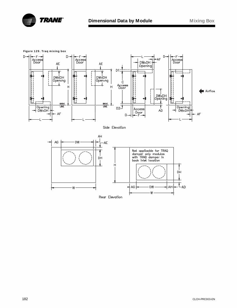
Dimensional Data by Module
182 CLCH-PRC003-EN
Figure 129. Traq mixing box
Mixing Box

Dimensional Data by Module
CLCH-PRC003-EN 183
Table 223. Traq mixing box dimensions
Unit Size
W L HC
w/out filters
Cwith
filtersF D
D1 w/out filters
D1 with
filtersD2
Without Airfoil Blade Dampers
DH DW AD AE AF AG AH
3 31.00 36.00 26.25 21.71 21.71 21.95 2.15 2.27 2.27 2.27 14.75 18.50 2.00 2.00 2.00 10.50 2.006 44.00 28.75 28.75 24.21 24.21 24.45 2.15 2.27 2.27 2.27 14.75 31.50 2.00 2.00 2.00 10.50 2.008 48.00 34.00 34.00 29.46 29.46 20.20 2.15 2.27 2.27 2.27 14.75 35.50 2.00 2.00 2.00 10.50 2.0010 60.00 34.00 34.00 29.46 29.46 20.20 2.15 2.27 2.27 2.27 14.75 42.50 2.00 2.00 2.00 8.75 8.7512 64.00 34.00 39.00 34.46 34.46 20.20 2.15 2.27 2.27 2.27 14.75 53.50 2.00 2.00 2.00 5.25 5.2514 68.00 34.00 40.50 35.96 35.96 20.20 2.15 2.27 2.27 2.27 20.50 43.50 2.00 2.00 2.00 12.25 12.2517 74.00 34.00 44.00 39.46 39.46 20.20 2.15 2.27 2.27 2.27 20.50 51.50 2.00 2.00 2.00 11.25 11.2521 76.00 50.25 50.25 45.71 45.71 21.83 2.15 2.27 2.27 2.27 20.50 63.50 2.00 2.00 2.00 6.25 6.2525 78.00 40.00 56.50 51.96 51.96 20.20 2.15 2.27 2.27 2.27 26.25 58.50 2.00 2.00 2.00 9.75 9.7530 91.00 56.50 56.50 51.96 51.96 24.95 2.15 2.27 2.27 2.27 26.25 68.50 2.00 2.00 2.00 11.25 11.2535 96.00 48.00 63.75 58.21 58.21 24.20 2.65 2.77 2.77 2.77 32.00 66.50 2.50 2.50 2.50 14.75 14.7540 109.00 48.00 63.75 58.21 58.21 24.20 2.65 2.77 2.77 2.77 32.00 79.50 2.50 2.50 2.50 14.75 14.7550 120.00 48.00 75.00 69.46 69.46 24.20 2.65 2.77 2.77 2.77 32.00 99.50 2.50 2.50 2.50 10.25 10.2557 120.00 48.00 86.50 71.58 80.96 24.20 2.65 12.15 2.77 2.77 37.75 115.00 2.50 2.50 2.50 2.50 2.5066 137.00 84.00 92.09 71.58 80.96 24.20 2.65 12.15 2.77 8.36 37.75 114.00 29.96 24.38 2.50 11.50 11.5080 137.00 92.00 107.09 71.58 95.96 24.20 2.65 27.15 2.77 8.36 43.50 115.50 34.58 29.01 2.50 10.75 10.75100 152.00 96.00 119.59 71.58 108.46 24.20 2.65 39.65 2.77 8.36 49.25 127.50 37.95 32.38 2.50 12.25 12.25120 179.00 96.00 119.59 71.58 108.46 24.20 2.65 39.65 2.77 8.36 49.25 156.50 37.95 32.38 2.50 11.25 11.25
Table 224. Traq mixing box dimensions with dampersUnit Size
With Airfoil Blade Dampers With Traq DampersDH DW AD AE AF AG AH DH DW AD AE AF AG AH
3 17.00 21.00 0.75 0.75 0.75 9.25 0.75 16.06 16.06 2.47 2.47 9.97 7.47 7.476 17.00 34.00 0.75 0.75 0.75 9.25 0.75 16.06 33.21 2.47 2.47 6.34 5.40 5.408 17.00 38.00 0.75 0.75 0.75 9.25 0.75 16.06 33.21 2.47 2.47 2.47 7.40 7.4010 17.00 45.00 0.75 0.75 0.75 7.50 7.50 16.06 52.86 4.22 4.22 4.22 3.57 3.5712 17.00 56.00 0.75 0.75 0.75 4.00 4.00 27.25 58.55 3.38 3.38 3.38 2.73 2.7314 22.75 46.00 0.75 0.75 0.75 11.00 11.00 19.75 62.06 2.36 2.36 2.36 2.97 2.9717 22.75 54.00 0.75 0.75 0.75 10.00 10.00 19.75 62.06 2.36 2.36 2.36 5.97 5.9721 22.75 66.00 0.75 0.75 0.75 5.00 5.00 29.65 63.65 2.18 2.18 2.18 6.18 6.1825 28.50 61.00 0.75 0.75 0.75 8.50 8.50 29.65 67.65 3.18 3.18 3.18 5.18 5.1830 28.50 71.00 0.75 0.75 0.75 10.00 10.00 24.75 80.44 7.63 7.63 7.63 5.28 5.2835 34.25 69.00 1.25 1.25 1.25 13.50 13.50 29.65 91.98 5.76 5.76 5.75 2.01 2.0140 34.25 82.00 1.25 1.25 1.25 13.50 13.50 29.65 100.65 6.55 6.55 6.55 4.18 4.1850 34.25 102.00 1.25 1.25 1.25 9.00 9.00 34.50 112.83 4.13 4.13 4.13 3.59 3.5957 40.00 117.00 1.25 1.25 1.25 1.50 1.50 34.50 112.83 4.13 4.13 4.13 3.59 3.5966 40.00 116.50 28.71 23.27 1.39 10.25 10.25 74.28 124.17 9.65 4.13 4.38 6.42 6.4280 45.75 118.00 33.47 27.90 1.39 9.50 9.50 74.50 124.17 9.59 4.13 6.38 6.42 6.42100 51.50 130.00 36.85 31.27 1.39 11.00 11.00 74.50 134.17 9.59 4.13 7.38 8.92 8.92120 51.50 159.00 36.85 31.27 1.39 10.00 10.00 74.50 152.17 9.59 4.13 7.38 13.42 13.42
(1) With Airfoil Blade Dampers are the dimensions to the outer edge of the damper flanges.(2) Without Airfoil Blade Dampers are the dimensions that represent the panel openings size 3-30 when only a damper opening is provided.(3) Without Airfoil Blade Dampers for size 35-120 the dimensions represent a channel frame openings when only a damper opening is provided.(4) With Traq Dampers, the DW and DH dimensions represent the outer most edges of the Traq Damper flange.(5) The base line does not include the height for mounting legs or base rail except for unit sizes 66 through 120 where the base rail is integral to the unit.(6) For unit sizes 3, 6 and 8, the dampers are not centered in the module. The AG dimension refers to the drive side of the unit.
Mixing Box

Dimensional Data by Module
184 CLCH-PRC003-EN
Moisture Eliminator
Figure 130. Moisture eliminator
Moisture Eliminator

Dimensional Data by Module
CLCH-PRC003-EN 185
Table 225. Moisture eliminator dimensionsUnit Size W L H A B D2 E L/2 J K ND (NPT)
3 31 11.00 26.25 27.00 22.25 2.00 2.00 5.50 0.80 2.60 1.006 44 11.00 28.75 40.00 24.75 2.00 2.00 5.50 0.80 2.60 1.008 48 11.00 34.00 44.00 30.00 2.00 2.00 5.50 0.80 2.60 1.0010 60 11.00 34.00 56.00 30.00 2.00 2.00 5.50 0.80 2.60 1.0012 64 11.00 39.00 60.00 35.00 2.00 2.00 5.50 0.80 2.60 1.0014 68 11.00 40.50 64.00 36.50 2.00 2.00 5.50 0.80 2.60 1.0017 74 11.00 44.00 70.00 40.00 2.00 2.00 5.50 0.80 2.60 1.0021 76 11.00 50.25 72.00 46.25 2.00 2.00 5.50 0.80 2.60 1.0025 78 11.00 56.50 74.00 52.50 2.00 2.00 5.50 0.80 2.60 1.0030 91 11.00 56.50 87.00 52.50 2.00 2.00 5.50 0.80 2.60 1.0035 96 11.50 63.75 91.00 58.75 2.50 2.50 5.75 1.20 3.60 1.2540 109 11.50 63.75 104.00 58.75 2.50 2.50 5.75 1.20 3.60 1.2550 120 14.50 75.00 115.00 70.00 2.50 2.50 7.25 1.20 3.60 1.2557 120 14.50 86.50 115.00 81.50 2.50 2.50 7.25 1.20 3.60 1.2566 137 14.50 92.08 132.00 81.50 8.00 2.50 7.25 5.80 2.50 1.5080 137 14.50 107.08 132.00 96.50 8.00 2.50 7.25 5.80 2.50 1.50100 152 14.50 119.58 147.00 109.00 8.00 2.50 7.25 5.80 2.50 1.50120 179 14.50 119.58 174.00 109.00 8.00 2.50 7.25 5.80 2.50 1.50
(1) Drain pan connection dimension is nominal pipe size. Indoor air quality drain pan connections can be either LH or RH but not both.(2) The base line does not include the height for mounting legs or base rail except for unit sizes 66 through 120 where the base rail is integral to the unit.
Moisture Eliminator

Dimensional Data by Module
186 CLCH-PRC003-EN
Multizone
Figure 131. Multizone module
Multizone

Dimensional Data by Module
CLCH-PRC003-EN 187
Table 226. Multizone dimensions (inches)Unit Size
W L* H C1 C2 F1 F2 HD D D1 D2 D3 AH AJ AK DH N
6 44 46.80 45.75 24.21 24.21 11.20 11.20 17.00 2.15 2.15 2.27 2.27 8.00 13.13 2.00 29.50 5.008 48 46.80 51.00 29.46 29.46 11.20 11.20 17.00 2.15 2.15 2.27 2.27 6.00 13.13 2.00 29.50 6.0010 60 46.80 54.00 29.46 29.46 11.20 11.20 20.00 2.15 2.15 2.27 2.27 6.00 16.13 2.00 35.50 8.0012 64 65.30 59.00 34.46 32.24 11.20 19.5 20.00 2.15 12.00 2.27 3.38 10.00 16.13 2.00 35.50 8.0014 68 65.30 60.50 35.96 33.74 11.20 19.5 20.00 2.15 12.00 2.27 3.38 8.00 16.13 2.00 35.50 9.0017 74 65.30 64.00 39.46 37.24 11.20 19.5 20.00 2.15 12.00 2.27 3.38 8.00 16.13 2.00 35.50 10.0021 76 65.30 73.25 45.71 43.49 11.20 19.5 23.00 2.15 12.00 2.27 3.38 10.00 19.13 2.00 41.50 10.0025 78 71.30 79.50 51.96 49.74 11.20 19.5 23.00 2.15 18.00 2.27 3.38 6.00 19.13 2.00 41.50 11.0030 91 71.30 79.50 51.96 49.74 11.20 19.5 23.00 2.15 18.00 2.27 3.38 7.00 19.13 2.00 41.50 13.0035 96 80.30 91.75 58.21 55.99 10.70 23.5 28.00 2.65 21.50 2.77 3.88 6.00 23.63 2.75 50.50 14.0040 109 80.30 91.75 58.21 55.99 10.70 23.5 28.00 2.65 21.50 2.77 3.88 7.00 23.63 2.75 50.50 16.0050 120 88.30 103.0 69.46 67.24 14.70 23.5 28.00 2.65 21.50 2.77 3.88 6.00 23.63 2.75 50.50 18.00
Unit Size A L1 L2 L3 G1 G2 G3 J K ND (NPT)6 40.00 15.50 15.50 15.50 39.05 23.40 7.75 0.80 2.60 1.008 44.00 15.50 15.50 15.50 39.05 23.40 7.75 0.80 2.60 1.0010 56.00 15.50 15.50 15.50 39.05 23.40 7.75 0.80 2.60 1.0012 60.00 15.50 15.50 34.00 57.55 41.90 17.00 0.80 2.60 1.0014 64.00 15.50 15.50 34.00 57.55 41.90 17.00 0.80 2.60 1.0017 70.00 15.50 15.50 34.00 57.55 41.90 17.00 0.80 2.60 1.0021 72.00 15.50 15.50 34.00 57.55 41.90 17.00 0.80 2.60 1.0025 74.00 15.50 15.50 40.00 63.55 47.90 20.00 0.80 2.60 1.0030 87.00 15.50 15.50 40.00 63.55 47.90 20.00 0.80 2.60 1.0035 92.00 16.00 16.00 48.00 72.30 56.15 24.00 1.20 3.60 1.2540 105.00 16.00 16.00 48.00 72.30 56.15 24.00 1.20 3.60 1.2550 116.00 20.00 20.00 48.00 78.30 58.15 24.00 1.20 3.60 1.25
(1) The drain pan connection dimension is nominal pipe size. Indoor air quality drain pan connections can be either left-hand or right-hand but not both.(2) Damper opening dimensions are to the outer edge of the damper frames.(3) Outward swing doors are dimensioned to door and inward swing doors (leaving module, sizes 12-50) are to door opening.(4) L* Combined module length includes module length plus gasket thickness.(5) Optional doors shown.(6) Optional drain pan show in air entering section.

Dimensional Data by Module
188 CLCH-PRC003-EN
Figure 132. Multizone double duct
Multizone

Dimensional Data by Module
CLCH-PRC003-EN 189
Table 227. Multizone double duct dimensions (inches)Unit Size
W L* H C1 C2 F1 F2 HD D D1 D2 D3 EDuct Opening
SAL AL1
6 44.00 46.50 45.75 24.21 24.21 11.20 11.20 17.00 2.15 2.15 2.27 2.27 2.00 13.00 13.00 4.008 48.00 46.50 51.00 29.46 29.46 11.20 11.20 17.00 2.15 2.15 2.27 2.27 2.00 13.00 13.00 4.0010 60.00 46.50 54.00 29.46 29.46 11.20 11.20 20.00 2.15 2.15 2.27 2.27 2.00 16.00 16.00 4.0012 64.00 65.00 59.00 34.46 32.24 11.20 19.5 20.00 2.15 12.00 2.27 3.38 2.00 16.00 16.00 4.0014 68.00 65.00 60.50 35.96 33.74 11.20 19.5 20.00 2.15 12.00 2.27 3.38 2.00 16.00 16.00 4.0017 74.00 65.00 64.00 39.46 37.24 11.20 19.5 20.00 2.15 12.00 2.27 3.38 2.00 16.00 16.00 4.0021 76.00 65.00 73.25 45.71 43.49 11.20 19.5 23.00 2.15 12.00 2.27 3.38 2.00 19.00 19.00 4.0025 78.00 71.00 79.50 51.96 49.74 11.20 19.5 23.00 2.15 18.00 2.27 3.38 2.00 19.00 19.00 4.0030 91.00 71.00 79.50 51.96 49.74 11.20 19.5 23.00 2.15 18.00 2.27 3.38 2.00 19.00 19.00 4.0035 96.00 80.00 91.75 58.21 55.99 10.70 23.5 28.00 2.65 22.00 2.77 3.88 2.50 23.00 23.00 5.0040 109.00 80.00 91.75 58.21 55.99 10.70 23.5 28.00 2.65 22.00 2.77 3.88 2.50 23.00 23.00 5.0050 120.00 88.00 103.00 69.46 67.24 14.70 23.5 28.00 2.65 22.00 2.77 3.88 2.50 23.00 23.00 5.00
Unit Size A L1 L2 L3 G1 G2 G3 J K ND (NPT)6 40.00 15.50 15.50 15.50 38.95 23.35 7.75 0.80 2.60 1.008 44.00 15.50 15.50 15.50 38.95 23.35 7.75 0.80 2.60 1.0010 56.00 15.50 15.50 15.50 38.95 23.35 7.75 0.80 2.60 1.0012 60.00 15.50 15.50 34.00 57.45 41.85 17.00 0.80 2.60 1.0014 64.00 15.50 15.50 34.00 57.45 41.85 17.00 0.80 2.60 1.0017 70.00 15.50 15.50 34.00 57.45 41.85 17.00 0.80 2.60 1.0021 72.00 15.50 15.50 34.00 57.45 41.85 17.00 0.80 2.60 1.0025 74.00 15.50 15.50 40.00 63.45 47.85 20.00 0.80 2.60 1.0030 87.00 15.50 15.50 40.00 63.45 47.85 20.00 0.80 2.60 1.0035 92.00 16.00 16.00 48.00 72.20 56.10 24.00 1.20 3.60 1.2540 105.00 16.00 16.00 48.00 72.20 56.10 24.00 1.20 3.60 1.2550 116.00 20.00 20.00 48.00 78.20 58.10 24.00 1.20 3.60 1.25
(1) The drain pan connection dimension is nominal pipe size. Indoor air quality drain pan connections can be either left-hand or right-hand but not both.(2) Outward swing doors are dimensioned to door and inward swing doors are to door opening. (3) L* Combined module length includes module length plus gasket thickness(4) Optional doors shown(5) Optional drain pan shown in air entering section
Multizone

Dimensional Data by Module
190 CLCH-PRC003-EN
Silencer
Figure 133. Rectangular silencer
Table 228. Silencer dimensionsUnit Size W H A B D D1 E 3 feet L 5 feet L
3 31 26.25 27 22.25 2.0 2.0 2.0 36 606 44 28.75 40 24.75 2.0 2.0 2.0 36 608 48 34.00 44 30.00 2.0 2.0 2.0 36 6010 60 34.00 56 30.00 2.0 2.0 2.0 36 6012 64 39.00 60 35.00 2.0 2.0 2.0 36 6014 68 40.50 64 36.50 2.0 2.0 2.0 36 6017 74 44.00 70 40.00 2.0 2.0 2.0 36 6021 76 50.25 72 46.25 2.0 2.0 2.0 36 6025 78 56.50 74 52.50 2.0 2.0 2.0 36 6030 91 56.50 87 52.50 2.0 2.0 2.0 36 6035 96 63.75 91 58.75 2.5 2.5 2.5 36 6040 109 63.75 104 58.75 2.5 2.5 2.5 36 6050 120 75.00 115 70.00 2.5 2.5 2.5 36 6057 120 86.50 115 81.50 2.5 2.5 2.5 36 6066 137 92.09 132 81.50 2.5 8.0 2.5 36 6080 137 107.09 132 96.50 2.5 8.0 2.5 36 60100 152 119.59 147 109.00 2.5 8.0 2.5 36 60120 179 119.59 174 109.00 2.5 8.0 2.5 36 60
Silencer

CLCH-PRC003-EN 191
Electrical Data
Table 229. Input line current requirements
Horsepower (hp)
Variable Frequency Drive Input Line Current (amps)
National Electric Code Motor Starter Current (amps)
200 230 460 575 200 230 460 5751.0 6.3 6.3 2.5 2.3 4.8 4.2 2.1 1.71.5 6.3 6.3 2.5 2.3 6.9 6.0 3.0 2.42.0 7.3 7.3 3.4 2.6 7.8 6.8 3.4 2.73.0 10.4 10.4 4.8 3.8 11.0 9.6 4.8 3.95.0 16.8 16.8 8.3 5.9 17.5 15.2 7.6 6.17.5 23.8 23.8 10.6 9.2 25.3 22.0 11.0 9.010.0 32.2 32.2 14.2 11.1 32.2 28.0 14.0 11.015.0 48.3 48.3 21.0 16.6 48.3 42.0 21.0 17.020.0 61.9 61.9 27.6 21.4 62.1 54.0 27.0 22.025.0 78.2 78.2 34.0 26.3 78.2 68.0 34.0 27.030.0 92.0 92.0 41.0 31.2 92.0 80.0 40.0 32.040.0 117.0 101.3 53.0 39.9 120.0 104.0 52.0 41.050.0 n/a 126.6 64.0 50.6 n/a 130.0 65.0 52.060.0 n/a n/a 77.0 60.4 n/a n/a 77.0 62.075.0 n/a n/a 104.0 75.0 n/a n/a 96.0 77.0100.0 n/a n/a 128.0 92.4 n/a n/a 124.0 99.0125.0 n/a n/a 157.0 n/a n/a n/a 156.0 n/a

192 CLCH-PRC003-EN
Notes

CLCH-PRC003-EN 193
InstallationConsiderations
Preparing the Unit SiteWhen selecting and preparing the unit site, follow these guidelines:
• Ensure that the site can support the total weight of the unit. Add the module weights for each unit using the data in the section. If a factory external support kit (base rail) is provided, refer to Table 231 for weights for the external support kit option.
• Allow sufficient space for service access. Figure 134 and Table 230 give the recommended space allowances for filter, coil, and fan shaft removal, as well as motor starter maintenance. Because unit configurations vary, refer to
Figure 134. Service Clearances
the unit submittals for specific location of access doors, accessories, motor starter, and other components.
• Ensure there is adequate height for condensate drain requirements.
• Confirm that the foundation of the mounting platform is large enough to accommodate the unit footprint plus service access. Refer to the unit submittals for specific dimensions.
Table 230. Service Clearance Dimensions
Unit Size
AFilter
BCoil
CFan
DStarter or VFD
3 48 48 48 606 48 60 48 608 48 64 48 6010 48 75 51 6012 48 79 54 6014 48 83 58 6017 48 89 61 6021 48 91 60 6025 48 93 66 6030 48 106 66 6035 48 110 65 6040 48 123 70 6050 48 134 77 6057 48 134 77 6066 52 150 93 6080 56 150 91 60100 58 165 101 60120 58 180 101 60

Installation Considerations
194 CLCH-PRC003-EN
Certain units may be suspended from the ceiling (see Figure 135). To suspend an M-Series air handler from the ceiling, use structural channels that run the full length of the unit. The support may be obtained from the factory as an external support kit or fabricated in the field as a support frame.
• Ensure that the floor or foundation is level for proper coil drainage and condensate flow.
• Allow the proper height for coil piping and condensate drain requirements. It may be necessary to elevate the unit when piping the condensate drain. Insufficient trap height could inhibit condensate drainage and flood the unit or equipment room.
• Provide permanent power outlets near the unit for power requirements during installation and maintenance.
• Temper the air in the equipment room, and verify that it is free from standing water.
Note: Refer to the M-Series air handler installation, operation, and maintenance manual, CLCH-SVX03C-EN, for detailed installation information.
� WARNING
Structural Failure!
Do not or suspend M-Series air
handlers from the top of the unit. To
suspend an M-Series air handler
from above, a factory-supplied
external support base kit of
fabricated support base frame must
be used. Failure to adequately
support the unit could result in
death or serious injury. See
Figure 135 for recommended
mounting configurations.
Figure 135. Ceiling Suspended Unit
Table 231. Weight Factors (lb.) for External Support KitUnit Size 3 6 8 10 12 14 17 21 25 30 35 40 50 57
A 3.7 3.7 3.7 3.7 3.7 3.7 3.7 3.7 3.7 3.7 3.7 3.7 3.7 3.7B1 23 29 30 36 37 39 42 43 43 49 51 57 62 62
1 B is the weight (lb.) for crossbars, lugs, and hardware on each shipping section.
Table 232. Shipping Length/Weight Limits for Single Piece ShipmentUnit Size
Maximum Unit Weight (lb)
Baserail Unit Maximum Unit Length (in)
Non-Baserail Unit Maximum Unit Length (in)
3–30 < 2,500 98 9635 < 3,900 98 9640 < 4,300 98 96
50–57 < 5,100 98 9666-120 n/a n/a n/a
The unit will not ship as a single piece if either weight or length is exceeded. These limits are based on a four-point lift.
External Support Kit WeightTo determine the weight of the external support kit, use the following equation with the factors A and B in Table 231:
Weight (lb.) = A × unit lgth (in.) + B
If the actual weight or length of the unit exceeds the maximum limit for single-piece shipment, the unit will ship in multiple pieces. Each piece will have its own base rail, so the base rail weight must be calculated for each piece. See Table 232 for shipping length and weight limits. Table 233 shows damper torque requirements.

Installation Considerations
CLCH-PRC003-EN 195
Table 233. Damper torque requirements (inch pound) at 1-inch w.g. air pressure drop
Unit Size Face Damper Internal Face-
and-BypassExternal Face-
and-BypassIntegral Face-
and-BypassMultizone1
Top Discharge Front Discharge3 16 17 27 10 N/A N/A6 24 29 40 17 5 78 33 39 52 26 5 710 43 50 66 31 6 812 56 62 81 36 6 814 60 69 87 41 6 817 78 83 107 62 6 821 92 99 122 62 7 1025 108 115 139 86 7 1030 127 136 163 86 7 1035 143 154 180 103 17 2440 160 172 201 103 17 2450 215 228 261 161 17 2457 253 267 299 161 n/a n/a66 307 308 404 201 n/a n/a80 364 364 460 221 n/a n/a100 460 460 569 314 n/a n/a120 549 549 678 314 n/a n/a
Unit Size
Mixing Module Dampers (Top-Back-Bottom Locations) Side Locations
Traq damper only
Bladed damper only
Traq damper linked to bladed
damper
Bladed damper linked to bladed
damper
Traq damper linked to Traq
damper
Bladed damper only
3 18 12 20 14 36 106 36 21 39 24 72 178 36 24 39 27 72 2210 54 29 58 33 108 3012 68 36 73 41 135 3614 68 41 73 47 135 4317 68 49 74 56 135 4921 72 60 81 69 144 5825 72 72 82 82 144 6730 99 84 111 96 198 8735 108 100 122 114 216 10240 108 115 125 132 216 11750 113 146 159 167 225 14857 113 199 211 227 225 16966 150 199 216 227 300 20080 188 233 254 266 375 240100 225 292 318 334 450 296120 225 353 379 404 450 342
1 Torque is per blade. Multiply blades required per zone by torque value to size actuator per zone.

196 CLCH-PRC003-EN
MechanicalSpecifications
M-Series air handlers must be rigged, lifted, and installed in strict accordance with the Installation, Operation, and Maintenance manual (CLCH-SVX03C-EN) for M-Series air handlers. The units are also to be installed in strict accordance with the specifications.
Units may be shipped fully assembled or disassembled to the minimum module size in accordance with shipping and job site requirements. Sizes 3 to 57 may be shipped on an integral shipping skid with 4-inch legs to mount the units on the housekeeping pad and to provide additional height to properly trap the condensate line.
Air-handling performance data shall be certified in accordance with ARI Standard 430. Air handlers with vaneaxial fans, air handlers with plenum fans, and vertical draw-thru air handlers in which the coil is mounted immediately below the fan module are outside the scope of ARI Standard 430 and, therefore, cannot receive ARI 430 certification.
Unit sound performance data shall be rated per ARI Standard 260 and reported as sound power. Sound power derived from ASHRAE algorithms is not acceptable because it does not represent tested acoustical performance.
Unit Construction The unit shall be constructed as a complete frame with removable panels. Removal of side panels shall not affect the structural integrity of the unit. The casing shall be able to withstand up to 6 in. wg positive or 4 in. wg negative static pressure. All exterior wall panels shall be made of galvanized steel. Closed-cell foam gasketing shall be provided where modules join to prevent air leakage.
Insulation
Modules shall be factory-insulated. Insulation and insulation adhesive shall comply with NFPA-90A requirements for flame spread and smoke generation. Insulation adhesive shall be UL-listed.
1-Inch Single-Wall Panels
Panels shall be insulated with 1-inch, 1 1/2-lb/ft³ or 3-lb/ft³ density insulation. Thermal resistance (R) shall be 4.17 ft²•h•ºF/Btu.
Double-Wall Solid Panels
Panels shall be of double-wall construction to facilitate cleaning of the unit interior. The interior wall shall be constructed of solid, galvanized steel. Insulation shall be 1 1/2-lb/ft³ or 3-lb/ft³ density. Thermal resistance (R) shall be 8.33 ft²•h•ºF/Btu.
Double-Wall Perforated Panels
Panels shall be of double wall construction, fabricated from perforated material over fiberglass insulation. The perforation spacing and hole size shall be such as to prevent insulation breakaway, flake off, or delamination when tested at 9,000 fpm, in accordance with UL specification 181. The interior wall shall be perforated to enhance acoustical performance. Thermal resistance (R) shall be 8.33 ft²•h•ºF/Btu.
Drain Pans
All coil, moisture eliminator, and intake modules shall be provided with an insulated, double-wall, galvanized or stainless-steel drain pan. To address indoor air quality (IAQ), the drain pan shall be sloped in two planes to eliminate stagnant water conditions and to promote positive drainage. Access modules may be provided with an “IAQ” drain pan.
Access Doors
Access doors shall be constructed with a double-wall, solid, galvanized-steel interior panel and a solid, galvanized-steel exterior panel. Gasketing shall be provided around the full perimeter of the doors to prevent air leakage. Surface-mounted handles shall be provided to allow quick access to the interior of the module and to prevent through-cabinet penetrations that could cause air leakage. Access doors shall be hinged and removable for quick, easy access.
View Windows
A glass window for viewing, capable of withstanding unit operating pressures, shall be provided in the door.
Marine Lights
A factory-mounted, weather-resistant (enclosed and gasketed), vapor-tight, incandescent light fixture shall be provided for access and/or fan modules. The fixture shall be complete with junction box, globe, aluminum globe guard, receptacle, and bulb (field wiring required).
External Support Kit (Optional)An external support kit constructed of galvanized steel shall be provided on the base of the unit. The external support kit may be used for ceiling suspension or external isolation, or as a housekeeping pad.

Mechanical Specifications
CLCH-PRC003-EN 197
FansThe fan type shall be provided as required for stable operation and optimum energy efficiency. The fan shall be statically and dynamically balanced at the factory as a complete fan assembly (fan wheel, motor, drive, and belts). The fan shaft shall not exceed 75 percent of its first critical speed at any cataloged speed. Fan wheels shall be keyed to the fan shaft to prevent slipping. The fan shafts shall be solid. The fan module shall be provided with an access door on the drive side of the fan.
FC Fan
The fan shall be a double-width, double-inlet, multiblade-type, forward-curved (FC) fan. The fan shall be equipped with self-aligning, antifriction bearings with an L-50 life of 200,000 hours as calculated per ANSI/AFBMA Standard 9. Fan performance shall be certified as complying with ARI Standard 430.
BC Fan
The fan shall be a double-width, double-inlet, multiblade-type backward-curved (BC) fan. The fan shall be equipped with self-aligning, antifriction bearings with an L-50 life of 200,000 hours as calculated per ANSI/AFBMA Standard 9. Fan performance shall be certified as complying with ARI Standard 430.
AF Fan
The fan shall be a double-width, double-inlet, multiblade-type, airfoil (AF) fan. The fan shall be equipped with self-aligning, antifriction bearings with an L-50 life of 200,000 hours, as calculated per ANSI/AFBMA Standard 9. Fan performance shall be certified as complying with ARI Standard 430.
Plenum (Plug) Fan
The fan shall be a single-width, single-inlet, multiblade-type, plenum fan. The fan blades shall be backward-inclined airfoil. Plenum fans shall be equipped with self-aligning, antifriction, pillow-block bearings with an L-50 life of 200,000 hours as calculated per ANSI/AFBMA Standard 9.
Airfoil Vaneaxial Fan
The fan shall be an airfoil vaneaxial type. The fan shall have tapered inlet and outlet shells over fan hub assemblies to uniformly accelerate air through the blade area. The fan shall include a cast aluminum diffuser with radially projected straightening vanes and airfoil cross sections to straighten air as it leaves the blades. The edge of the vanes shall be curved to reduce tonal noise generation. Airfoil vaneaxial fans shall be equipped with self-aligning, antifriction bearings with an L-50 life of 200,000 hours as calculated per ANSI/AFBMA Standard 9. Bearing grease lines shall extend through the fan shell for easy servicing. The fan shall be AMCA 210 performance certified.
Fan Modulation
Variable-Frequency Drives
For variable-air-volume applications, airflow shall be modulated by a variable-frequency drive that controls fan speed.
Fan Isolation
The fan shall be isolated from the unit casing by a flexible connection.
1-Inch, Seismic Spring Isolators
The fan and motor assembly (on sizes 3 to 8) shall be internally isolated from the unit casing with 1-inch (25.3-mm) deflection spring isolators, furnished and installed by the unit manufacturer. The isolation system shall be designed to resist loads produced by external forces, such as earthquakes, and conform to the current requirements for Seismic Zone IV.
2-Inch, Seismic Spring Isolators
The fan and motor assembly (on sizes 10 to 120) shall be internally isolated from the unit casing with 2-inch (50.8-mm) deflection spring isolators, furnished and installed by the unit manufacturer. The isolation system shall be designed to resist loads produced by external forces, such as earthquakes, and conform to the current requirements for Seismic Zone IV.
Fan Drives
• Variable Pitch. The drives shall be variable pitch, suitable for adjustment within five percent of the specified speed.
• Fixed Pitch. The drives shall be constant speed with fixed-pitch sheaves.
• 1.2 Service Factor. The drives shall be selected at a minimum 20 percent larger than the motor horsepower.
• 1.5 Service Factor. The drives shall be selected at a minimum 50 percent larger than the motor horsepower.

Mechanical Specifications
198 CLCH-PRC003-EN
Fan Motors
The motor shall be integrally mounted to an isolated fan assembly furnished by the unit manufacturer. The motor shall be mounted inside the unit casing on an adjustable base to permit adjustment of drive-belt tension. The motor shall be a high-efficiency, T-frame, squirrel cage with size, type, and electrical characteristics as shown on the equipment schedule.
• Open Drip-Proof. The motor shall be open and drip-proof.
• Totally Enclosed Fan-Cooled (TEFC). The motor shall be totally enclosed and fan-cooled.
Motor Options
• 208–230 V, 3 ph, 60 Hz
• 460 V, 3 ph, 60 Hz
• 575 V, 3 ph, 60 Hz
• 220 V, 1 ph, 60 Hz
• NEMA Premium-efficiency motors
Fan Module Options
Grease Lines
Bearings are selectable with life-time lubrication or with relubrication required. For any bearing requiring relubrication, the grease line shall be extended to the fan-support bracket on the drive side.
Belt Guard
Unit sizes 35 to 120 shall be provided with a galvanized, expanded-metal belt guard that totally encloses the drive. The belt guard shall be rigidly attached to the bearing support structure and have a two-piece removable front panel. A tachometer hole shall be provided opposite the fan shaft. The belt guard shall be OSHA-approved and of a universal size to accommodate any applicable drive configuration.
Guard Screen
The plenum (plug) fan module shall be provided with an expanded-metal guard screen for the access door.
Coils
Horizontal and Vertical
Coil Modules
The coil module shall be provided complete with coil and coil holding frame. If two or more cooling coils are stacked in the unit, an intermediate drain pan shall be installed between each coil to drain condensate to the main drain pan without passing condensate through the air stream of the lower coil. The coils shall be manufactured by the supplier of the air-handling unit. The coils shall be installed such that headers and return bends are enclosed by unit casings.
Inspection Section
The coil module shall include an inspection section complete with a double-wall, removable door downstream of the coil for inspection, cleaning, and maintenance.
Water Coils (UW, UU, W, 5W, 5A,
WD, 5D, D, DD, K, P, or TT)
The coils shall have aluminum fins and seamless copper tubes. Copper fins may be applied to coils with 5/8-inch tubes. Fins shall have collars drawn, belled, and firmly bonded to tubes by mechanical expansion of the tubes. The coil casing may be galvanized or stainless steel. The coils shall be proof-tested to 300 psig and leak-tested under water to 200 psig. Coil performance data and coils containing water or ethylene glycol shall be certified in accordance with ARI Standard 410. Propylene glycol and calcium chloride, or mixtures thereof, are outside the scope of ARI Standard 410 and, therefore, do not require ARI 410 rating or certification.
Headers are to be constructed of round copper pipe or cast iron.
• Tubes shall be 1/2-inch OD, 0.016-inch copper.
• Tubes shall be 1/2-inch OD, 0.025-inch copper.
• Tubes shall be 5/8-inch OD, 0.020-inch copper.
• Tubes shall be 5/8-inch OD, 0.024-inch copper.
• Tubes shall be5/8-inch OD, 0.035-inch copper.
Refrigerant Cooling Coils (UF or F)
The coils shall have aluminum fins and seamless copper tubes. Copper fins may be applied to coils with 5/8-inch tubes. The fins shall have collars drawn, belled, and firmly bonded to tubes by mechanical expansion of the tubes. The coil casing may be galvanized or stainless steel.
The coils shall be proof-tested to 450 psig and leak-tested to 300 psig air pressure under water. After testing, the inside of the coils shall be dried, all connections shall be sealed, and the coil shall be shipped with a charge of dry nitrogen.
Suction headers shall be constructed of copper tubing. Suction connections shall penetrate unit casings to permit sweat connections to refrigerant lines. The coils shall have equalizing vertical distributors sized according to the capacities of the coils. Coil performance data shall be certified in accordance with ARI Standard 410.

Mechanical Specifications
CLCH-PRC003-EN 199
Steam Heating Coils (N or NS)
The coils shall have aluminum fins and seamless copper tubes. Copper fins may be applied to coils with1-inch tubes. The fins shall have collars drawn, belled, and firmly bonded to tubes by mechanical expansion of the tubes. The coil casing may be galvanized or stainless steel. Non-freeze, steam-distributing-type coils shall be provided. Steam coils shall be pitched in the unit for proper drainage of steam condensate from coils. The coils shall be proof-tested to 300 psig and leak-tested to 200 psig air pressure under water. Headers are to be constructed of round copper pipe or cast iron. Inner tubes shall have orifices that ensure even steam distribution throughout the full length of the outer tube. Orifices shall be directed toward the return connections to ensure that the steam condensate is adequately removed from the coil. Coil performance data shall be certified in accordance with ARI Standard 410.
• Tube construction shall be 11/16-inch OD, 0.031-inch copper inner tube, and 1-inch OD copper outer tube.
• Tube construction shall be 11/16-inch OD, 0.031-inch copper inner tube and 1-inch OD, 0.049-inch, red-brass outer tube.
Integral Face-and-Bypass
Coil Modules
A module consisting of a horizontal- or vertical-tube, integral face-and-bypass coil shall be provided. The coils shall be installed such that the headers and return bends are enclosed by the unit casings. The coils shall be sized as required to meet the scheduled capacity using steam or hot water, as specified. The integral face-and-bypass coils shall consist of a built-in series of finned heating elements and bypasses with interlocked dampers. Coil performance shall be certified in accordance with ARI Standard 410.
Integral Face-and-Bypass
Coil Option. Integral face-and-bypass coils shall be provided with a factory-mounted damper actuator.
Electric Heating
Coil Modules
An electric heater shall be factory-installed in the air handler. The heater shall be an open-coil configuration with Type A wire derated to a maximum watt density of 45 watts per square inch. Safeties shall include three-pole, disconnecting-type contactors, airflow switches, automatic-reset functional limits, automatic-reset high-temperature limits, and manual-reset high-temperature limits. Electric heaters above 48 amps shall be fused into circuits not to exceed 48 amps as required by UL and NEC. Kilowatt output shall be selected to the nearest 0.1 kW of scheduled kilowatt up to a maximum 28ºF rise at nominal airflow. Basic controls (external thermostat or relay control) shall be installed with the proper staging for the voltage and kilowatt specified.
Power Options
• 208 V, 3 ph
• 240 V, 3 ph
• 480 V, 3 ph
• 600 V, 3 ph
Contactor Options
Magnetic Contactors The contactors for energizing the electric heater shall be magnetic contactors.
FiltersFilter modules shall have filter racks, at least one access door for filter removal, and filter block-offs to prevent air bypass around filters. The modules shall be supplied with 2-inch or 4-inch flat, or 2-inch or 4-inch angled, bag, cartridge, or HEPA filters.
Permanent Filters
The filters shall be 2-inch, all-metal, capable of operating up to 625-fpm face velocity without loss of filter efficiency and holding capacity. The filter media shall be layers of cleanable wire mesh. The filter frame shall be constructed of galvanized steel. The filters shall have a rated average dust-spot efficiency of less than 20 percent (MERV 2 rating) when tested in accordance with the ASHRAE Standard 52 atmospheric-dust-spot method.
Throwaway Filters
The filters shall be throwaway-type and shall have 2-inch fiberglass media contained in a rigid frame. Filters shall be capable of operating up to 500-fpm face velocity without loss of filter efficiency and holding capacity. Filters shall have a rigid supporting mesh across the leaving face of the media. (MERV 5 rating)
Pleated Media Filters
The filters shall be 2-inch or 4-inch-thick, nonwoven fabric, treated with adhesive and continuously laminated to a supported steel-wire grid. Filters shall be capable of operating up to 625-fpm face velocity without loss of filter efficiency and holding capacity. The filters shall have a rated average dust-spot efficiency of 25- to 35- percent (MERV 6 to 7 rating) when tested in accordance with the ASHRAE Standard 52.2 atmospheric-dust-spot method.

Mechanical Specifications
200 CLCH-PRC003-EN
Bag Filters
The filters shall be fine-fiber, all-glass media with spun backing to keep glass fibers from eroding downstream. The stitching method shall permit the bag to retain its pleated shape without the use of a wire-basket support. The filters shall be capable of operating up to 625-fpm face velocity without loss of filter efficiency and holding capacity.
The filters shall be sealed into a metal header. The gasket material shall be installed on the metal header of the filter to prevent filter bypass where the metal headers meet the side-access racks. All bag filters shall be furnished with a 2-inch prefilter to extend bag filter life.
The manufacturer shall supply a side-access filter rack capable of holding bag filters and prefilters.
Bag filters shall have a 65- to 95-percent dust-spot efficiency (MERV 12 to 14 rating) based on ASHRAE Standard 52.2.
Cartridge Filters
The filters shall be constructed with a continuous sheet of fine-fiber media made into closely spaced pleats with safe-edged aluminum separators. The filters shall be capable of operating up to 625-fpm face velocity for 12-inch-deep filters and up to 312-fpm face velocity for 6-inch deep filters without loss of filter efficiency and holding capacity.
The filters shall be sealed into a metal frame assembled in a rigid manner. The gasket material shall be installed on the metal header of the filter to prevent filter bypass where the metal headers meet on the side-access racks.
All cartridge filters shall be furnished with a 2-inch prefilter to provide extended cartridge life. The manufacturer shall supply a side-access filter rack capable of holding cartridge filters and prefilters. Cartridge filters shall have a 65- to
95-percent dust-spot efficiency (MERV 11 to 14 rating) based on ASHRAE Standard 52.2.
4-Inch High-Efficiency
Filters
The filters shall be constructed with a fine fiber media made into closely spaced pleats. The filters shall be capable of operating up to 625-fpm face velocity without loss of filter efficiency and holding capacity. The filter media shall be sealed into a frame assembled in a rigid manner. All 4-inch high-efficiency filters shall be furnished with a 2-inch prefilter to provide extended filter life. The manufacturer shall supply a side-access filter rack capable of holding 4-inch high-efficiency filters and prefilters. Filters are available in 65-, 85-, and 95-percent efficiencies (MERV 11 to 14 rating) based on ASHRAE Standard 52.2.
HEPA Filters
The HEPA filter section shall have enclosed, front-loading-type, HEPA filters with an efficiency of not less than 99.97 percent. Holding frames shall be mounted in the casing and shall be leak free. Neoprene rubber gasketing shall be applied on the leaving-air side of the filter to reduce leakage. A fold design shall be used to increase the media surface area and reduce media damage during handling and installation. The filters shall be capable of operating up to 500-fpm face velocity without loss of filter efficiency and holding capacity.
HEPA filtration shall have 99.97-percent dust-spot efficiency (MERV rating not applicable)
Mixing and Bypass
Mixing Box, Filter Mixing
Box, Airflow Measurement
Station (Traq Dampers),
and Economizer Modules
A module shall be provided to support the damper assembly for outdoor, return, and/or exhaust air.
Dampers
Dampers shall modulate the volume of outdoor, return, or exhaust air. The dampers shall be of double-skin airfoil design with metal, compressible jamb seals and extruded-vinyl blade-edge seals on all blades. The blades shall rotate on stainless-steel sleeve bearings. The dampers shall be rated for a maximum leakage rate of 3 cfm/ft² at 1 in. wg and 8 cfm/ft² at 4 in. wg. Dampers may be arranged in a parallel or opposed-blade configuration.
Airflow Measurement
Station (Traq Dampers)
A factory-mounted airflow measurement station shall be provided in the outdoor- and/or return-air opening to measure airflow. The damper blades shall be galvanized steel, housed in a galvanized steel frame and mechanically fastened to a rotating axle rod. The damper shall be rated for a maximum leakage rate of one percent of nominal airflow at 1 in. wg. The airflow measurement station shall measure from 15 percent to 100 percent of unit nominal airflow. The airflow measurement station shall adjust for temperature variations and shall provide a 2 to 10 Vdc signal that corresponds to actual airflow for controlling and documenting airflow. The accuracy of the airflow measurement station shall be ±5 percent.

Mechanical Specifications
CLCH-PRC003-EN 201
Internal and External
Face-and-Bypass Modules
Low-leakage, face-and-bypass dampers shall be provided as scheduled on drawings. The dampers shall be of double-skin, airfoil design with metal, compressible jamb seals and extruded-vinyl blade-edge seals on all blades. The blades shall rotate on stainless-steel sleeve bearings. The dampers shall be rated for a maximum leakage rate of 5 cfm/ft² at 1 in. wg and 9 cfm/ft² at 4 in. wg. The dampers shall be arranged in an opposed-blade configuration. The face damper and bypass damper shall be mechanically linked together and provided with end-driven control shafts.
Other Modules and Options
Access/Inspection
Modules
A module shall be provided to allow additional access/inspection of unit components and space for field-installed components as needed. An access door or removable panels shall be provided for easy access.
Blender Modules
Blender module shall be provided to properly mix outdoor and return air, to prevent air stratification, and to reduce the risk of coil freeze-up. Blender modules shall be supplied and installed by the air handler manufacturer. The proper blender size and space upstream and downstream shall conform to the manufacturer’s recommendations to allow for proper performance. Blender modules shall meet or exceed cataloged mixing capabilities.
Diffuser Modules
A diffuser module shall be provided immediately downstream of the fan module. The diffuser shall provide equal air distribution to blow-thru components immediately downstream of the diffuser.
Humidifier Modules
The humidifier shall be designed for building steam. The humidifier shall include a fabricated separator/header and a multiple-steam-jacketed-dispersion-tube design, with all wetted parts constructed of stainless steel. All active tube-to-header (steam-handling) joints shall be welded.
The assembly shall include inactive tubes to minimize heat gain while shortening non-impinging vapor trail. The humidifier module shall provide a uniform discharge of steam. The control valve shall be protected by a steam-supply strainer and an inverted-bucket trap. All pipe connections shall be made from one side of the air handler.
Intake Modules
An intake module shall be provided with a heavy-duty bird screen on the entering face, followed by a maintenance-free moisture eliminator with galvanized “sine-wave” fins. The module shall be provided with an insulated, double-wall, galvanized or stainless-steel drain pan. To promote good indoor air quality, the drain pan shall be sloped in two planes to eliminate stagnant water conditions and to promote positive drainage.
Moisture Eliminator
Module
A module consisting of a vertically mounted, maintenance-free moisture eliminator shall be provided. The moisture eliminator shall have galvanized-steel, “sine-wave” fins for effective moisture removal.
Multizone Modules
Multizone dampers shall be of double-skin airfoil design with metal, compressible jamb seals and extruded-vinyl blade-edge seals on all blades. The blades shall rotate on stainless-steel sleeve bearings. The dampers shall be rated for a maximum leakage rate of 11 cfm/ft² at 1 in. wg.
Turning and Discharge
Plenum Modules
Plenums shall be provided to efficiently turn air and provide sound attenuation.
Controls
Combination Starter–
Disconnects
An IEC starter–disconnect combination shall be provided for each fan motor. Each starter–disconnect shall be properly sized, mounted, and wired to the motor by the air handler manufacturer. IEC starter–disconnects shall include a circuit breaker.
The starters shall include a control transformer with fusing and secondary grounding, Hand-Off-Auto (H-O-A) switch, two normally open auxiliary contacts, overload heaters, and manual reset overloads. Units with factory-mounted controls shall also include power wiring from the starter control transformer to the control system transformers, and start–stop wiring from the direct digital controller start–stop relay to the starter H-O-A switch.
Starters–disconnects shall have full metal enclosures with welded seams. The door shall be removable for ease of wiring and service.
Starter–Disconnect
Enclosure Options
• NEMA Type 1
• NEMA Type 4/Type 12

Mechanical Specifications
202 CLCH-PRC003-EN
Combination Variable-
Frequency Drive and
Disconnects
Combination variable-frequency drives (VFDs) and disconnects shall be provided for each fan motor. Each VFD–disconnect shall be properly sized, mounted, wired to the fan motor, and commissioned by the air handler manufacturer to facilitate temporary heating, cooling, ventilation, and/or timely completion of the project.
The combination VFD–disconnect shall include the VFD, a circuit-breaker disconnect, a drive-off switch, and manual speed-control.
Units with factory-mounted controls shall include a control transformer with sufficient capacity to support both the VFD and controls requirements, binary output on/off wiring, analog output-speed-signal wiring, and all interfacing wiring between the VFD and the direct digital controller.
The VFD shall include the following minimal protective features:
• Current-limited stall prevention
• Auto restart after momentary power loss
• Speed search for starting into rotating motor
• Anti-windmill with DC injection before start
• Phase-to-phase short-circuit protection
• Ground-fault protection
The VFD–disconnect shall be supplied with an instantaneous, short-circuit-trip circuit breaker. A through-the-door interlocking handle shall be spring loaded and designed to rest only in the full On or Off state. A concealed defeater mechanism shall allow entry into the enclosure when the handle is in the On position. A heavy-duty, snap-action, flange-operated, fusible disconnect switch is also acceptable. The blades shall be visible in the Off position. A terminal guard shall be supplied on the line-side terminals.
The VFD–disconnect shall have a
NEMA Type 1 enclosure.
The VFD shall be UL508C-listed and CSA-certified and shall conform to applicable NEMA, ICS, NFPA, IEC, and ISO 9001 standards.
Optional Bypass
Bypass circuitry with a drive-bypass switch shall be provided. The bypass switch is a four-position switch with Auto/Off/Bypass Hand/Bypass Auto operation.
Factory-Mounted
DDC Systems
Factory-mounted direct-digital control (DDC) systems shall be engineered, mounted, wired, and tested by the air handler manufacturer to reduce installed costs, improve reliability, and save time at unit startup. Each control system shall be fully functional in a stand-alone mode or may be tied to a building automation system with a single pair of twisted wires. All factory-mounted controls shall be covered by the air handler manufacturer’s standard warranty.
Direct Digital Controller
Factory-Configured Controller
A dedicated, factory-configured controller with the appropriate point capabilities shall be unit-mounted on each air-handling unit. The controller shall be factory-configured to reduce installed costs, improve reliability, and save time at unit startup. A portable touch pad shall be provided to facilitate local monitoring, troubleshooting, and changing of setpoints. The touch pad shall be able to quickly plug into other factory-configured controllers by the same manufacturer.
Field-Programmable Controller
A dedicated, programmable, direct digital controller with the appropriate point capabilities shall be unit-mounted on each air-handling unit. A screen and keypad shall be provided to facilitate local monitoring, troubleshooting, and changing of setpoints.

Mechanical Specifications
CLCH-PRC003-EN 203
Factory-Mounted Control
Options—Electronic
End Devices
Mixing Box Damper Actuators
Spring return actuators shall be mounted with the outdoor air damper linked as normally closed and the return-air damper linked as normally open.
Airflow Measuring Stations (Traq
Dampers)
Airflow monitoring stations shall provide a 2 to 10 Vdc signal, which corresponds to cfm, for controlling and documenting airflow.
Face-and-Bypass Damper Actuators
Spring-return actuators shall be linked as indicated on the order and the control drawings.
Multizone Damper Actuators
Nonspring-return actuators shall be linked as indicated on the order and the control drawings.
Inlet-Guide-Vane Actuators
Spring-return actuators shall be mounted with the inlet guide vanes linked as normally closed. On units larger than size 66, nonspring return is acceptable, but a static-pressure high-limit switch shall be provided to protect the ductwork.
Fan Discharge Temperature Sensors
A thermistor-type sensor shall be mounted in the fan discharge.
Averaging Temperature Sensors
A 1,000 ohm at 0ºC, platinum 385 curve, resistive temperature detector shall be serpentined across the module. Bends of the capillaries shall be curved and fastened with capillary clips to prevent crimping and minimize wear.
Low-Limit Switches
A manual-reset, double-pole, single-throw, low-limit switch shall be serpentined across the face of the coil module. The bends of the capillaries shall be curved and fastened with capillary clips to prevent crimping and minimize wear.
Airflow Switches
A differential pressure switch piped to the discharge and suction sides of the fan shall indicate fan status.
Dirty Filter Switches
A differential pressure switch piped to both sides of the filter shall indicate filter status.
Customer Interface Relays
Five-amp double-pole, double-throw relays shall be provided as required for each binary output of the controller for customer interface to:
• Motor starters of supply, return, and exhaust fans
• Relief dampers
• Pumps
• Condensing units
Field-Mounted
Control Options
Control Valves
Control valves shall be provided by the air-handling unit (AHU) manufacturer and field-piped by the piping contractor. Power and signal wiring shall be by a simple quick connect provided by the air handler manufacturer.
Space Temperature Sensors
Thermistor-type sensors shall be provided as required for field wiring.
Outdoor Air Sensors
Thermistor-type sensors shall be provided as required for field wiring.

TraneA businesss of American Standard Companieswww.trane.com
For more information, contact your local Trane office or e-mail us at [email protected]
Trane has a policy of continuous product and product data improvement and reserves the right to change design and specifications without notice.
Literature Order Number CLCH-PRC003-EN
File Number PL-AH-CLCH-PRC003-EN-1205
Supersedes CLCH-PRC003-EN September 2002
Stocking Location La Crosse
Literature References
For additional information, refer to the following Trane literature:
CLCH-PRC008-ENFan Performance Data for M-Series and T-Series Climate Changer Air Handlers, Sizes 3 to 120
CLCH-SVX03C-ENInstallation, Operation, and Maintenance for M-Series Climate Changer Air Handlers
CLCH-PRB020-ENTrane CDQ™ Desiccant Dehumidification engineering Bulletin
CLCH-PRB012-ENEnergy Wheel Overview for Modular and T-Series Climate Changer Air Handlers
SYS-AM-15Managing Building Moisture
SYS-APM003-ENAir-to-Air Energy Recovery in HVAC Systems
CLCH-PRB005-ENSplit Dehumidification Unit for Modular Climate Changer Air Handlers
BAS-PRC001-ENTracer Summit Building Automation System
CLCH-PRC006-ENType A Energy Wheel for Modular and T-Series Climate Changer Air Handlers