m. sawan, d. - pppl
TRANSCRIPT
FIRE Vacuum Vessel
and Remote Handling
Overview
B. Nelson, T. Burgess, T. Brown, H-M Fan, G. Jones, C. Kessel,
M. Sawan, D. Driemeyer, M. Ulrickson, D. Strickler, D. Williamson
Snowmass
July 13, 2002
13 July 2002 Snowmass Review: FIRE Vacuum Vessel and Remote Handling 2
Presentation Outline
• Vacuum Vessel− Design requirements
− Design concept and features
− Analysis to date
− Status and summary
• Remote Handling− Maintenance Approach & Component Classification
− In-Vessel Transporter
− Component Replacement Time Estimates
− Balance of RH Equipment
• Design and analysis are consistent with pre-conceptualphase, but demonstrate basic feasibility of concepts
13 July 2002 Snowmass Review: FIRE Vacuum Vessel and Remote Handling 3
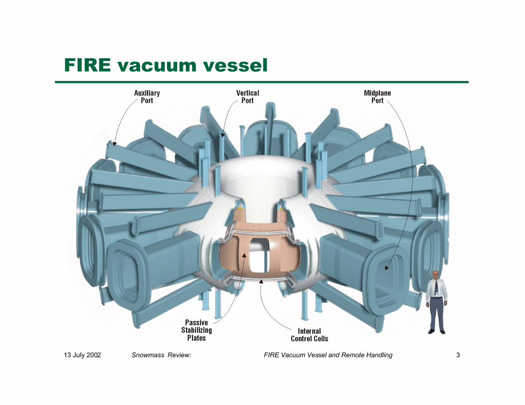
FIRE vacuum vessel
13 July 2002 Snowmass Review: FIRE Vacuum Vessel and Remote Handling 4
Vacuum vessel functions
• Plasma vacuum environment
• Primary tritium confinement boundary
• Support for in-vessel components
• Radiation shielding
• Aid in plasma stabilization− conducting shell
− internal control coils
• Maximum access for heating/diagnostics
13 July 2002 Snowmass Review: FIRE Vacuum Vessel and Remote Handling 5
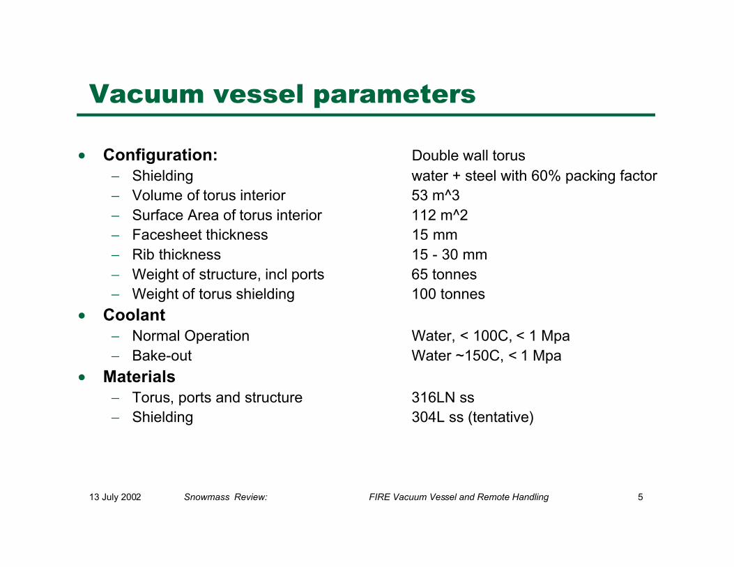
Vacuum vessel parameters
• Configuration: Double wall torus− Shielding water + steel with 60% packing factor− Volume of torus interior 53 m^3− Surface Area of torus interior 112 m^2− Facesheet thickness 15 mm− Rib thickness 15 - 30 mm− Weight of structure, incl ports 65 tonnes− Weight of torus shielding 100 tonnes
• Coolant− Normal Operation Water, < 100C, < 1 Mpa− Bake-out Water ~150C, < 1 Mpa
• Materials− Torus, ports and structure 316LN ss− Shielding 304L ss (tentative)
13 July 2002 Snowmass Review: FIRE Vacuum Vessel and Remote Handling 6
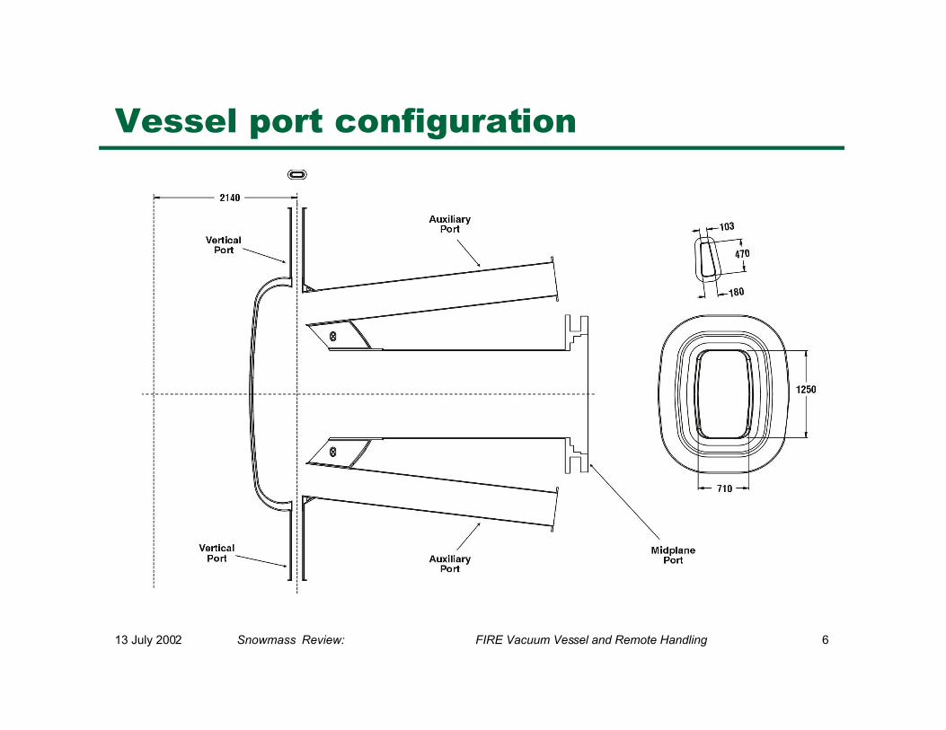
Vessel port configuration
13 July 2002 Snowmass Review: FIRE Vacuum Vessel and Remote Handling 7
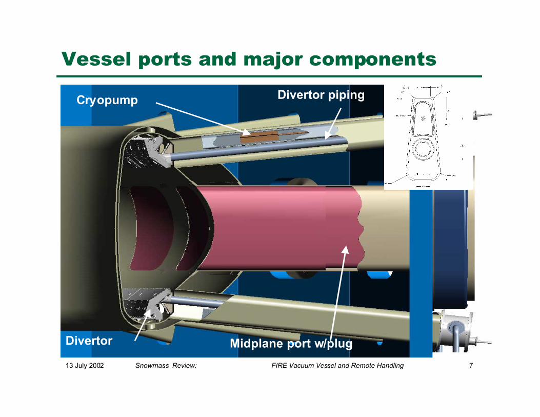
Vessel ports and major components
Divertor pipingCryopump
Midplane port w/plugDivertor
13 July 2002 Snowmass Review: FIRE Vacuum Vessel and Remote Handling 8
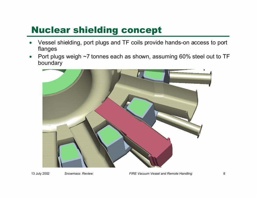
Nuclear shielding concept• Vessel shielding, port plugs and TF coils provide hands-on access to port
flanges• Port plugs weigh ~7 tonnes each as shown, assuming 60% steel out to TF
boundary
13 July 2002 Snowmass Review: FIRE Vacuum Vessel and Remote Handling 9
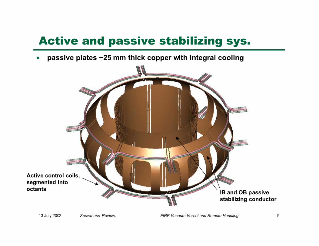
Active control coils,segmented intooctants
IB and OB passivestabilizing conductor
Active and passive stabilizing sys.• passive plates ~25 mm thick copper with integral cooling
13 July 2002 Snowmass Review: FIRE Vacuum Vessel and Remote Handling 10
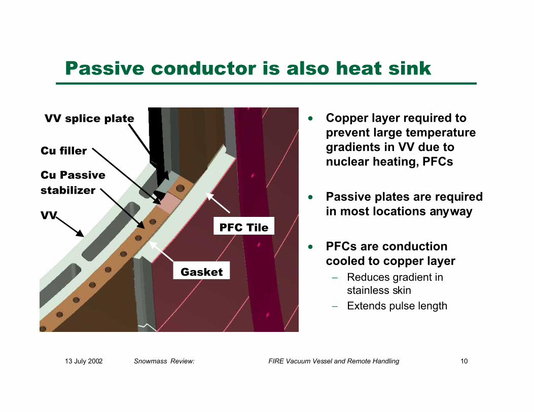
Passive conductor is also heat sink
• Copper layer required toprevent large temperaturegradients in VV due tonuclear heating, PFCs
• Passive plates are requiredin most locations anyway
• PFCs are conductioncooled to copper layer
− Reduces gradient instainless skin
− Extends pulse length
VVPFC Tile
Cu Passivestabilizer
Cu filler
Gasket
VV splice plate
13 July 2002 Snowmass Review: FIRE Vacuum Vessel and Remote Handling 11
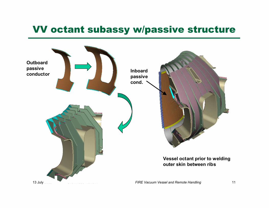
VV octant subassy w/passive structure
Vessel octant prior to weldingouter skin between ribs
Outboardpassiveconductor
Inboardpassivecond.
13 July 2002 Snowmass Review: FIRE Vacuum Vessel and Remote Handling 12
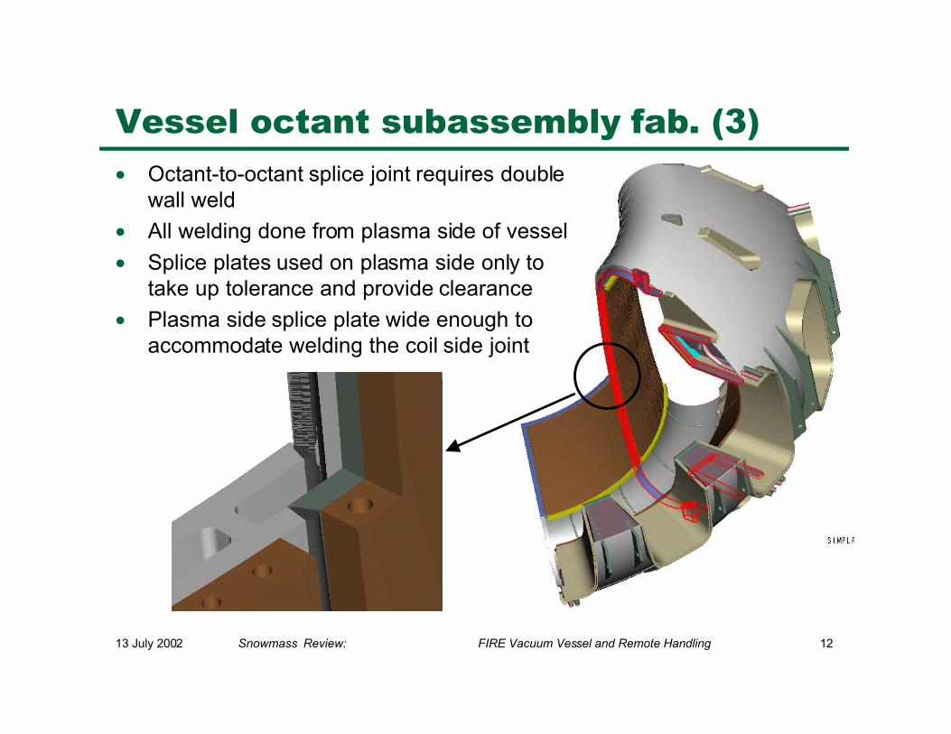
Vessel octant subassembly fab. (3)
• Octant-to-octant splice joint requires doublewall weld
• All welding done from plasma side of vessel
• Splice plates used on plasma side only totake up tolerance and provide clearance
• Plasma side splice plate wide enough toaccommodate welding the coil side joint
13 July 2002 Snowmass Review: FIRE Vacuum Vessel and Remote Handling 13
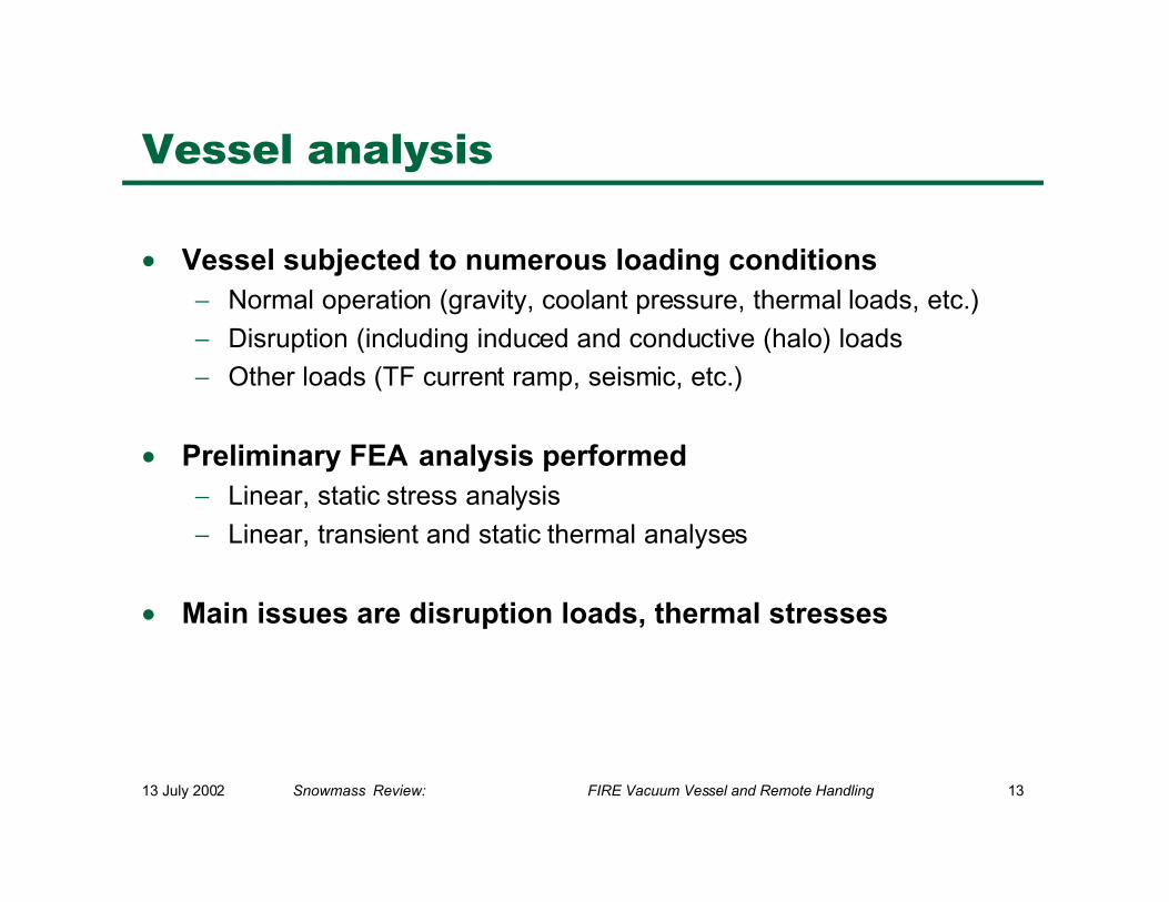
Vessel analysis
• Vessel subjected to numerous loading conditions− Normal operation (gravity, coolant pressure, thermal loads, etc.)
− Disruption (including induced and conductive (halo) loads
− Other loads (TF current ramp, seismic, etc.)
• Preliminary FEA analysis performed− Linear, static stress analysis
− Linear, transient and static thermal analyses
• Main issues are disruption loads, thermal stresses
13 July 2002 Snowmass Review: FIRE Vacuum Vessel and Remote Handling 14
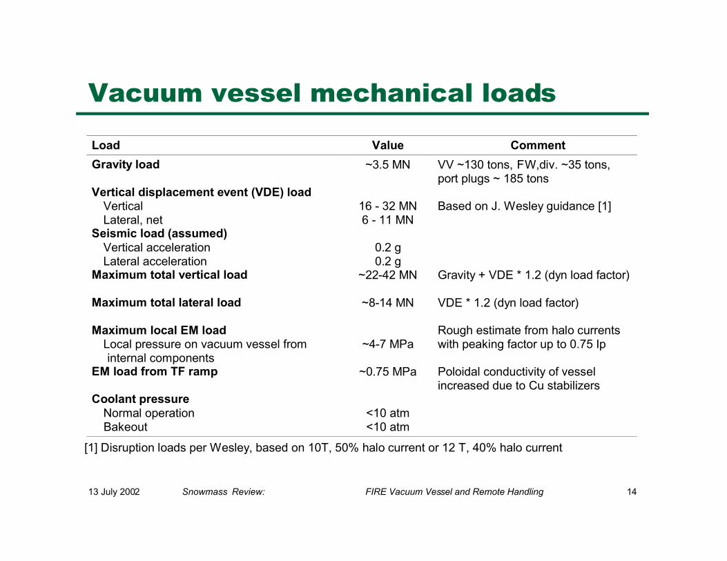
Vacuum vessel mechanical loads
Load Value Comment
Gravity load ~3.5 MN VV ~130 tons, FW,div. ~35 tons,port plugs ~ 185 tons
Vertical displacement event (VDE) loadVerticalLateral, net
16 - 32 MN6 - 11 MN
Based on J. Wesley guidance [1]
Seismic load (assumed)Vertical accelerationLateral acceleration
0.2 g0.2 g
Maximum total vertical load ~22-42 MN Gravity + VDE * 1.2 (dyn load factor)
Maximum total lateral load ~8-14 MN VDE * 1.2 (dyn load factor)
Maximum local EM loadLocal pressure on vacuum vessel frominternal components
~4-7 MPaRough estimate from halo currentswith peaking factor up to 0.75 Ip
EM load from TF ramp ~0.75 MPa Poloidal conductivity of vesselincreased due to Cu stabilizers
Coolant pressureNormal operationBakeout
<10 atm<10 atm
[1] Disruption loads per Wesley, based on 10T, 50% halo current or 12 T, 40% halo current
13 July 2002 Snowmass Review: FIRE Vacuum Vessel and Remote Handling 15
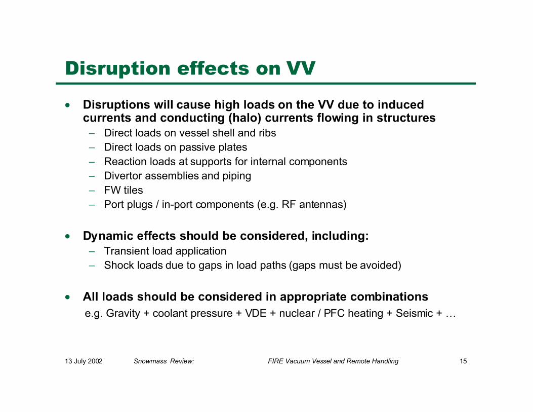
Disruption effects on VV
• Disruptions will cause high loads on the VV due to inducedcurrents and conducting (halo) currents flowing in structures
− Direct loads on vessel shell and ribs− Direct loads on passive plates− Reaction loads at supports for internal components− Divertor assemblies and piping− FW tiles− Port plugs / in-port components (e.g. RF antennas)
• Dynamic effects should be considered, including:− Transient load application− Shock loads due to gaps in load paths (gaps must be avoided)
• All loads should be considered in appropriate combinations e.g. Gravity + coolant pressure + VDE + nuclear / PFC heating + Seismic + …
13 July 2002 Snowmass Review: FIRE Vacuum Vessel and Remote Handling 16
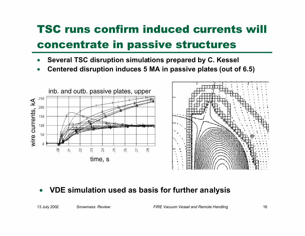
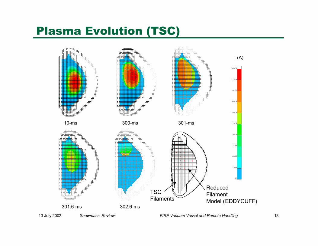
TSC runs confirm induced currents willconcentrate in passive structures• Several TSC disruption simulations prepared by C. Kessel• Centered disruption induces 5 MA in passive plates (out of 6.5)
• VDE simulation used as basis for further analysis
13 July 2002 Snowmass Review: FIRE Vacuum Vessel and Remote Handling 17
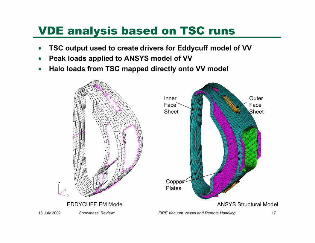
VDE analysis based on TSC runs
• TSC output used to create drivers for Eddycuff model of VV
• Peak loads applied to ANSYS model of VV
• Halo loads from TSC mapped directly onto VV model
CopperPlates
InnerFaceSheet
OuterFace Sheet
EDDYCUFF EM Model ANSYS Structural Model
13 July 2002 Snowmass Review: FIRE Vacuum Vessel and Remote Handling 18
Plasma Evolution (TSC)
I (A)
10-ms 300-ms 301-ms
301.6-ms 302.6-ms
ReducedFilamentModel (EDDYCUFF)
TSCFilaments
13 July 2002 Snowmass Review: FIRE Vacuum Vessel and Remote Handling 19
Constant Current VectorsProportional Current Vectors
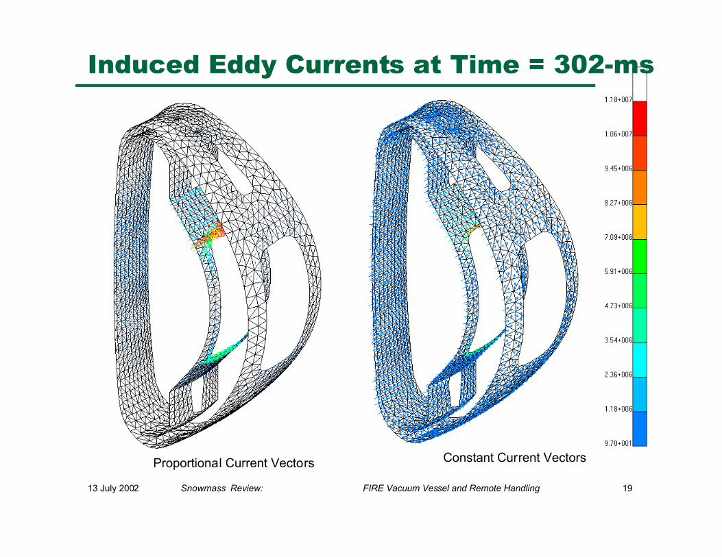
Induced Eddy Currents at Time = 302-ms
13 July 2002 Snowmass Review: FIRE Vacuum Vessel and Remote Handling 20
0.E+00
1.E+06
2.E+06
3.E+06
4.E+06
5.E+06
6.E+06
7.E+06
8.E+06
0.29
8
0.29
9
0.30
0
0.30
1
0.30
2
0.30
3
0.30
4
0.30
5
Time (s)
Pla
sma
Cu
rren
t (A
)
ip-toroidal
ip-halo
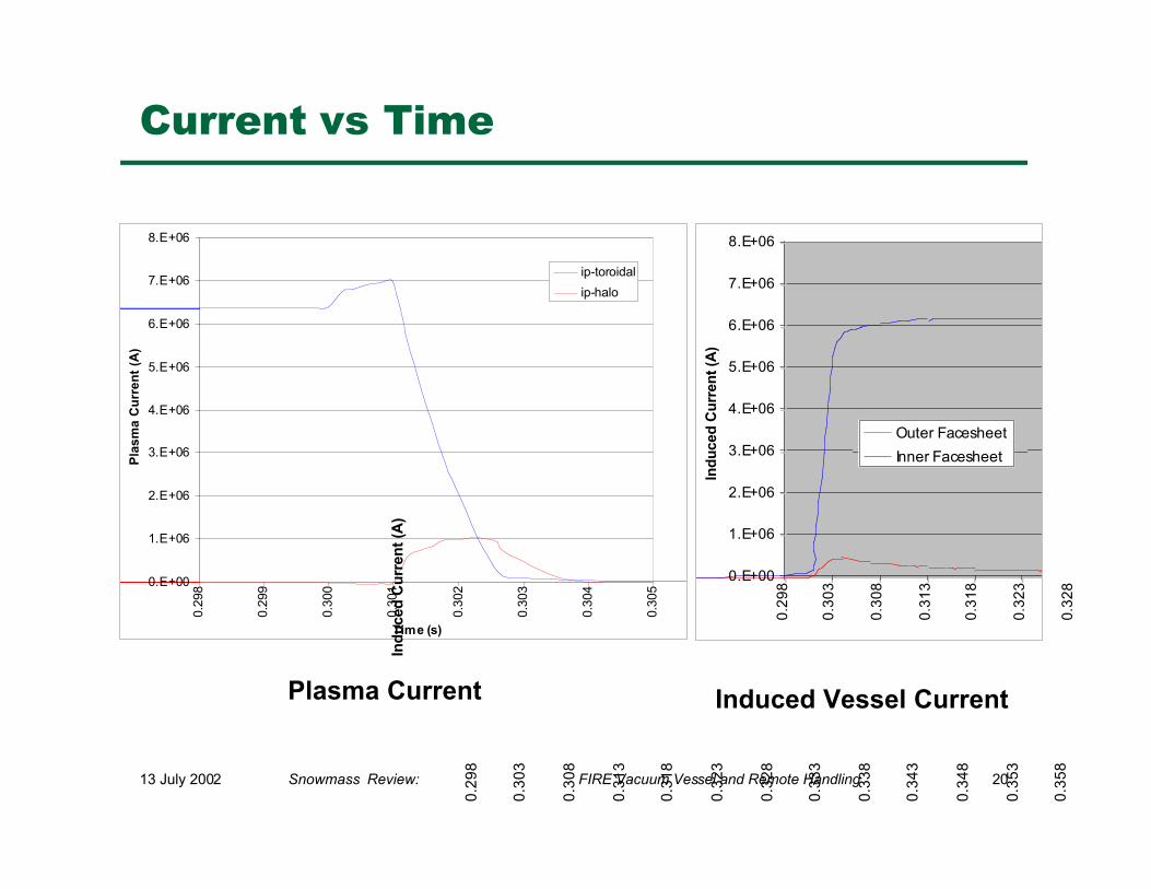
Current vs Time
Plasma Current
0.E+00
1.E+06
2.E+06
3.E+06
4.E+06
5.E+06
6.E+06
7.E+06
8.E+06
0.2
98
0.3
03
0.3
08
0.3
13
0.3
18
0.3
23
0.3
28
Ind
uce
d C
urr
ent
(A)
0.2
98
0.3
03
0.3
08
0.3
13
0.3
18
0.3
23
0.3
28
0.3
33
0.3
38
0.3
43
0.3
48
0.3
53
0.3
58
Ind
uce
d C
urr
ent
(A)
Outer Facesheet
Inner Facesheet
Induced Vessel Current
13 July 2002 Snowmass Review: FIRE Vacuum Vessel and Remote Handling 21
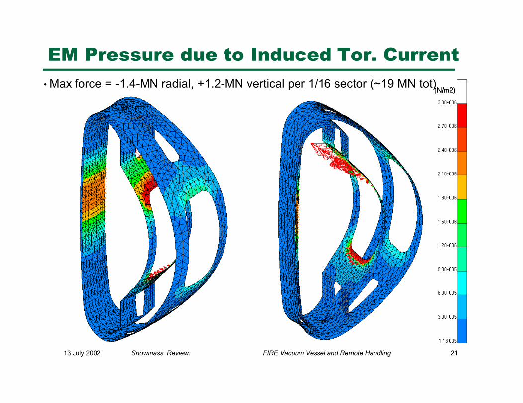
EM Pressure due to Induced Tor. Current
• Max force = -1.4-MN radial, +1.2-MN vertical per 1/16 sector (~19 MN tot)
13 July 2002 Snowmass Review: FIRE Vacuum Vessel and Remote Handling 22
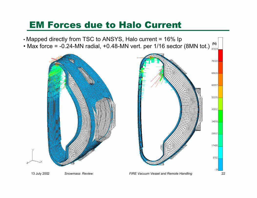
EM Forces due to Halo Current
• Mapped directly from TSC to ANSYS, Halo current = 16% Ip• Max force = -0.24-MN radial, +0.48-MN vert. per 1/16 sector (8MN tot.)
13 July 2002 Snowmass Review: FIRE Vacuum Vessel and Remote Handling 23
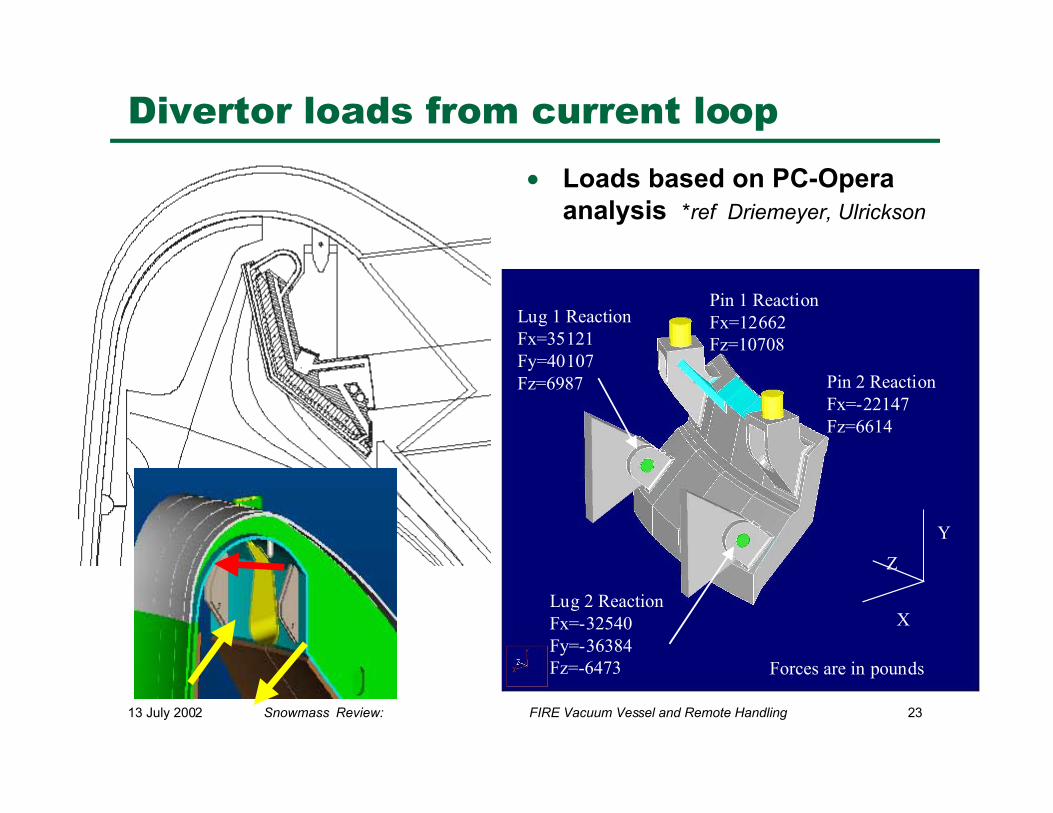
Y
X
Z
Pin 1 ReactionFx=12662Fz=10708
Pin 2 ReactionFx=-22147Fz=6614
Lug 1 ReactionFx=35121Fy=40107Fz=6987
Lug 2 ReactionFx=-32540Fy=-36384Fz=-6473 Forces are in pounds
Divertor loads from current loop
• Loads based on PC-Operaanalysis *ref Driemeyer, Ulrickson
13 July 2002 Snowmass Review: FIRE Vacuum Vessel and Remote Handling 24
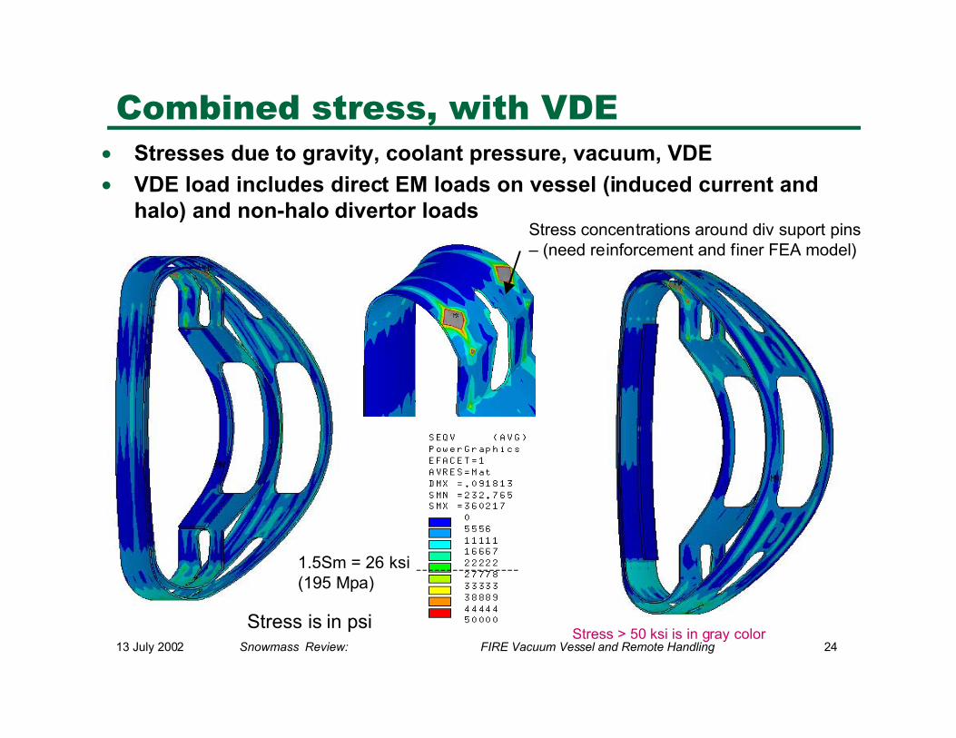
Combined stress, with VDE• Stresses due to gravity, coolant pressure, vacuum, VDE
• VDE load includes direct EM loads on vessel (induced current andhalo) and non-halo divertor loads
Stress > 50 ksi is in gray colorStress is in psi
1.5Sm = 26 ksi(195 Mpa)
Stress concentrations around div suport pins– (need reinforcement and finer FEA model)
13 July 2002 Snowmass Review: FIRE Vacuum Vessel and Remote Handling 25
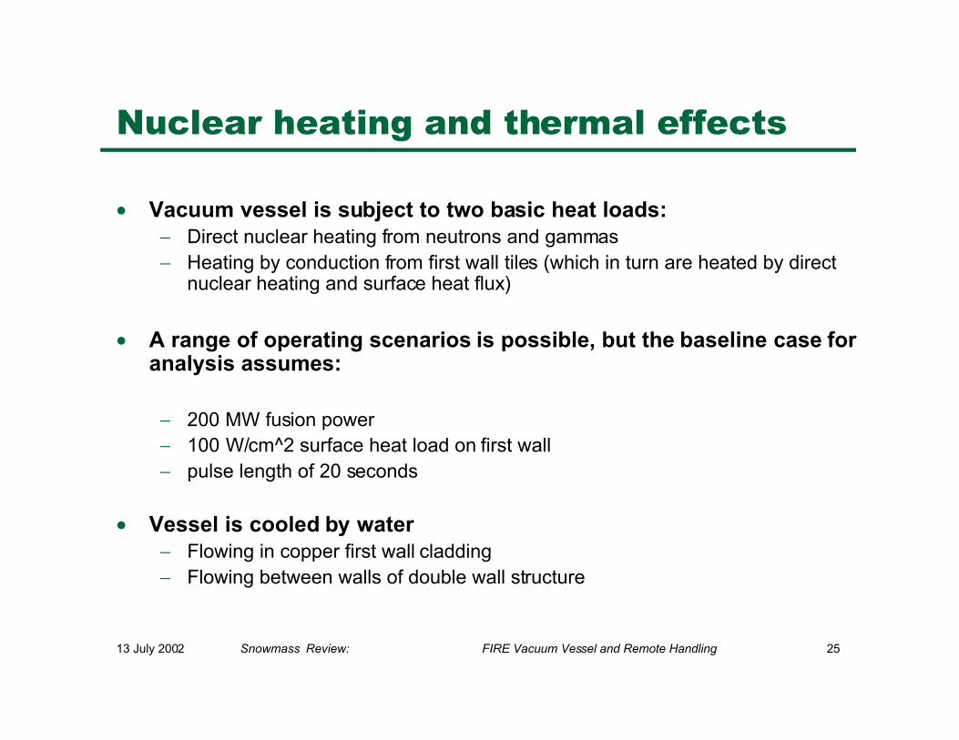
Nuclear heating and thermal effects
• Vacuum vessel is subject to two basic heat loads:− Direct nuclear heating from neutrons and gammas− Heating by conduction from first wall tiles (which in turn are heated by direct
nuclear heating and surface heat flux)
• A range of operating scenarios is possible, but the baseline case foranalysis assumes:
− 200 MW fusion power− 100 W/cm^2 surface heat load on first wall− pulse length of 20 seconds
• Vessel is cooled by water− Flowing in copper first wall cladding− Flowing between walls of double wall structure
13 July 2002 Snowmass Review: FIRE Vacuum Vessel and Remote Handling 26
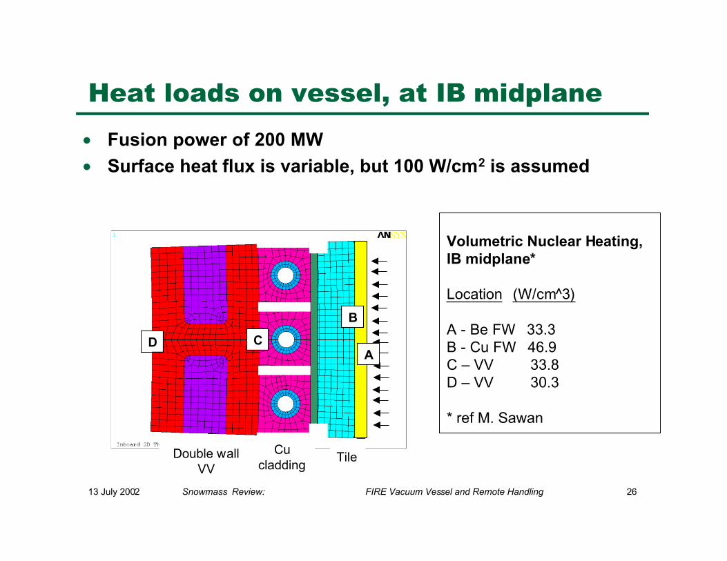
Heat loads on vessel, at IB midplane
• Fusion power of 200 MW
• Surface heat flux is variable, but 100 W/cm2 is assumed
D C
B
TileCu
claddingDouble wall
VV
A
Volumetric Nuclear Heating,IB midplane*
Location (W/cm^3)
A - Be FW 33.3B - Cu FW 46.9C – VV 33.8D – VV 30.3
* ref M. Sawan
13 July 2002 Snowmass Review: FIRE Vacuum Vessel and Remote Handling 27
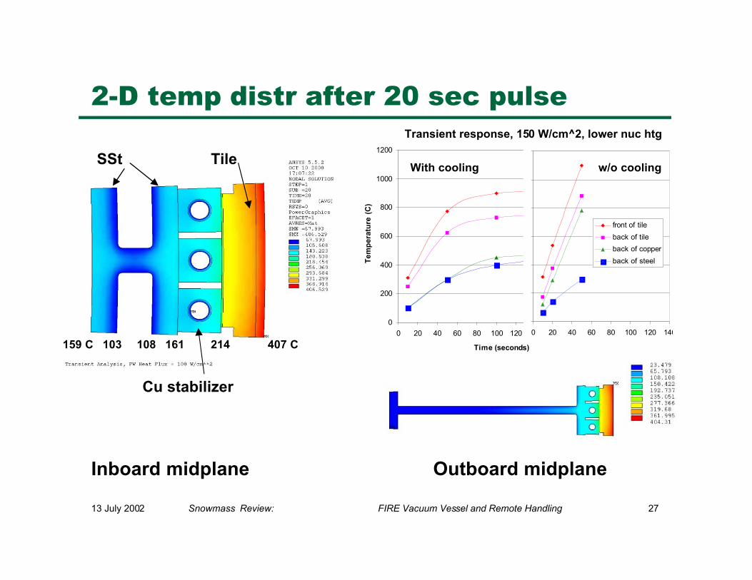
2-D temp distr after 20 sec pulse
Inboard midplane Outboard midplane
TileSSt
Cu stabilizer
159 C 103 108 161 214 407 C
0
200
400
600
800
1000
1200
0 20 40 60 80 100 120 140
Time (seconds)
Te
mp
era
ture
(C
)
With cooling
Transient response, 150 W/cm^2, lower nuc htg
0 20 40 60 80 100 120 140
front of tile
back of tile
back of copper
back of steel
w/o cooling
13 July 2002 Snowmass Review: FIRE Vacuum Vessel and Remote Handling 28
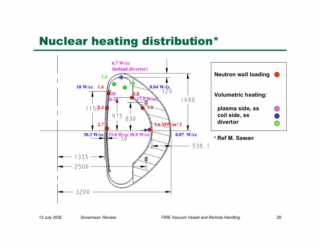
1.6
2.4
2.7
2.0
3.0
3.6 MW/m^2
6.7 W/cc(behind divertor)
1.81.4
33.8 W/cc 30.9 W/cc30.3 W/cc 0.07 W/cc
18 W/cc
17.9 W/cc
0.04 W/cc 20W/cc
Nuclear heating distribution*
* Ref M. Sawan
Neutron wall loading
Volumetric heating:
plasma side, ss coil side, ss divertor
13 July 2002 Snowmass Review: FIRE Vacuum Vessel and Remote Handling 29
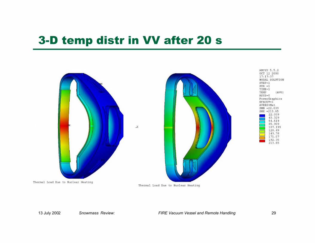
3-D temp distr in VV after 20 s
13 July 2002 Snowmass Review: FIRE Vacuum Vessel and Remote Handling 30
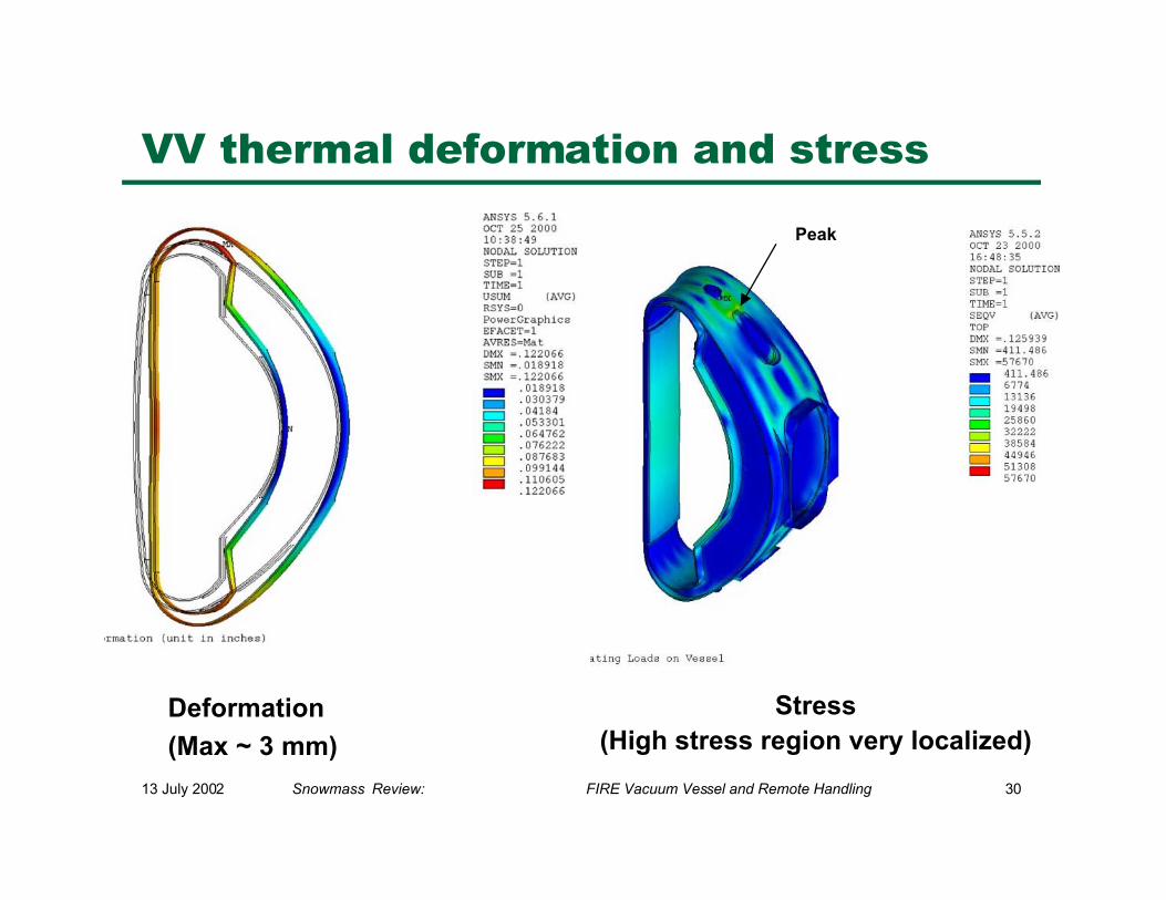
VV thermal deformation and stress
Stress(High stress region very localized)
Peak
Deformation
(Max ~ 3 mm)
6 June 2001 FIRE Review: Vacuum Vessel Design 45
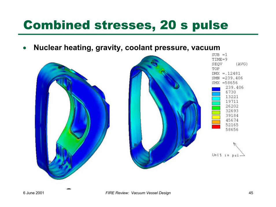
Combined stresses, 20 s pulse• Nuclear heating, gravity, coolant pressure, vacuum
13 July 2002 Snowmass Review: FIRE Vacuum Vessel and Remote Handling 32
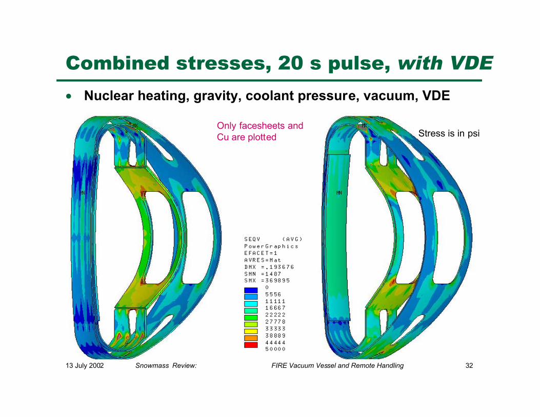
Combined stresses, 20 s pulse, with VDE
• Nuclear heating, gravity, coolant pressure, vacuum, VDE
Only facesheets andCu are plotted Stress is in psi
13 July 2002 Snowmass Review: FIRE Vacuum Vessel and Remote Handling 33
Conclusions of vessel analysis
• Can vessel take disruption loads? YES− but additional load cases must be run using updated geometry
• Can vessel achieve pulse length? ITS CLOSE− 20 second pulse should be achieveable− Thicker tiles, external heaters are options to be explored for more
margin
• What next?− Optimized geometry and refined FEA models− Revised load cases, including lower fusion power, lower surface
heat flux, higher plasma current− Dynamic analysis− Fatigue analysis, including plastic effects
13 July 2002 Snowmass Review: FIRE Vacuum Vessel and Remote Handling 34
Remote Handling*
• Maintenance Approach & Component Classification
• In-Vessel Transporter
• Component Replacement Time Estimates
• Balance of RH Equipment
*ref T. Burgess
13 July 2002 Snowmass Review: FIRE Vacuum Vessel and Remote Handling 35
Remote Maintenance Approach
• Hands-on maintenance employed to the fullest extent possible.Activation levels outside vacuum vessel are low enough to permithands-on maintenance.
• In-vessel components removed as integral assemblies andtransferred to the hot cell for repair or processing as waste.
• In-vessel contamination contained by sealed transfer casks thatdock to the VV ports.
• Midplane ports provide access to divertor, FW and limitermodules. Port mounted systems (heating and diagnostics) arehoused in a shielded assembly that is removed at the portinterface.
13 July 2002 Snowmass Review: FIRE Vacuum Vessel and Remote Handling 36
Remote Maintenance Approach (2)
• Upper and lower auxiliary ports house diagnostic and cryopumpassemblies that are also removable at the port interface.
• Remote operations begin with disassembly of port assemblyclosure plate.
• During extended in-vessel operations (e.g., divertor changeout), ashielded enclosure is installed at the open midplane port to allowhuman access to the ex-vessel region.
• Remote maintenance drives in-vessel component design andinterfaces. Components are given a classification and preliminaryrequirements are being accommodated in the layout of facilitiesand the site.
13 July 2002 Snowmass Review: FIRE Vacuum Vessel and Remote Handling 37
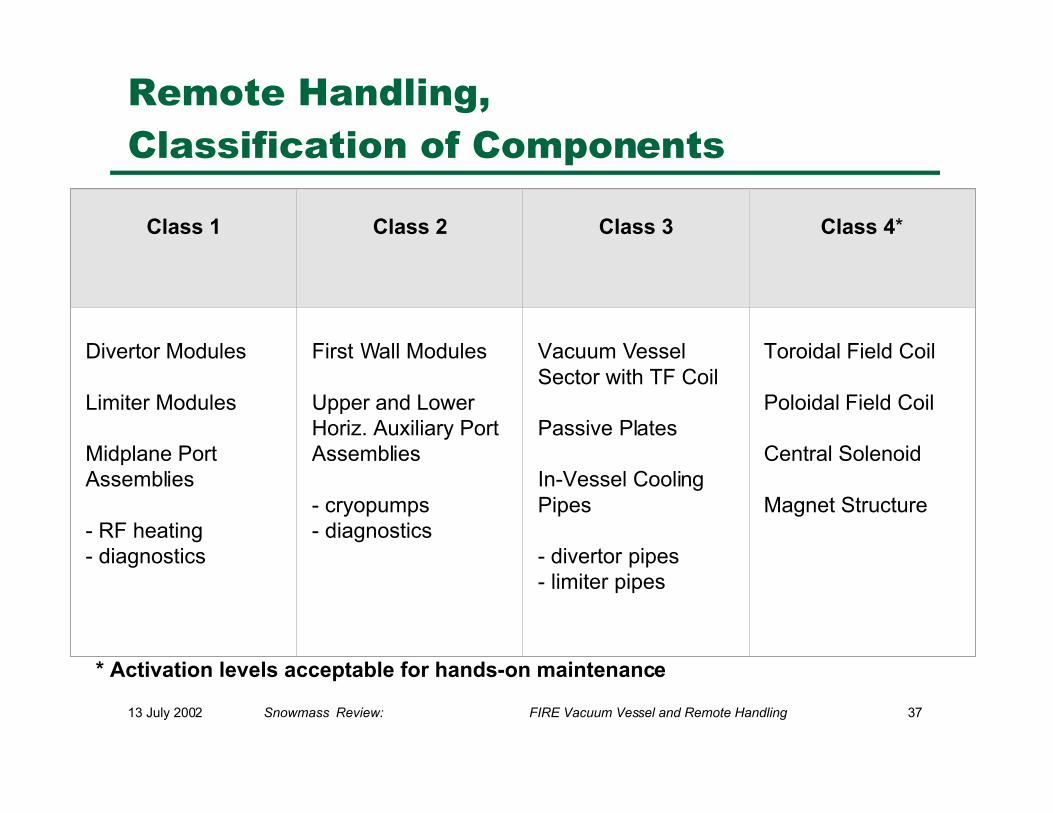
Remote Handling,Classification of Components
* Activation levels acceptable for hands-on maintenance
Class 1 Class 2 Class 3 Class 4*
Divertor Modules Limiter Modules Midplane PortAssemblies - RF heating- diagnostics
First Wall Modules Upper and LowerHoriz. Auxiliary PortAssemblies - cryopumps- diagnostics
Vacuum VesselSector with TF Coil Passive Plates In-Vessel CoolingPipes - divertor pipes- limiter pipes
Toroidal Field Coil Poloidal Field Coil Central Solenoid Magnet Structure
13 July 2002 Snowmass Review: FIRE Vacuum Vessel and Remote Handling 38
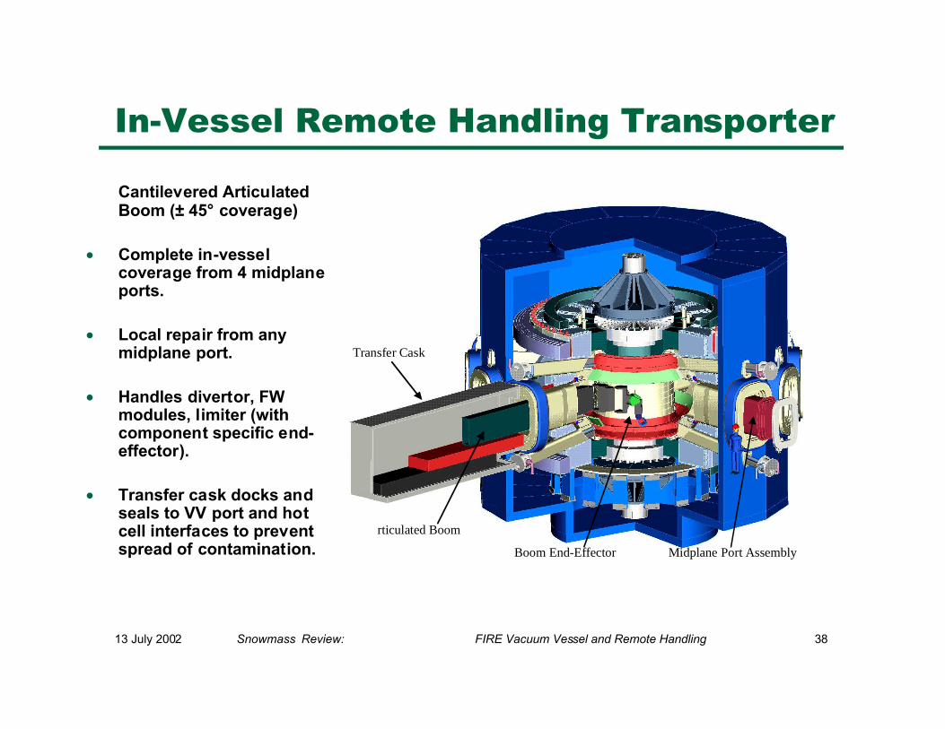
In-Vessel Remote Handling Transporter
Cantilevered ArticulatedBoom (± 45° coverage)
• Complete in-vesselcoverage from 4 midplaneports.
• Local repair from anymidplane port.
• Handles divertor, FWmodules, limiter (withcomponent specific end-effector).
• Transfer cask docks andseals to VV port and hotcell interfaces to preventspread of contamination.
i
Transfer Cask
rticulated Boom
Boom End-Effector Midplane Port Assembly
13 July 2002 Snowmass Review: FIRE Vacuum Vessel and Remote Handling 39
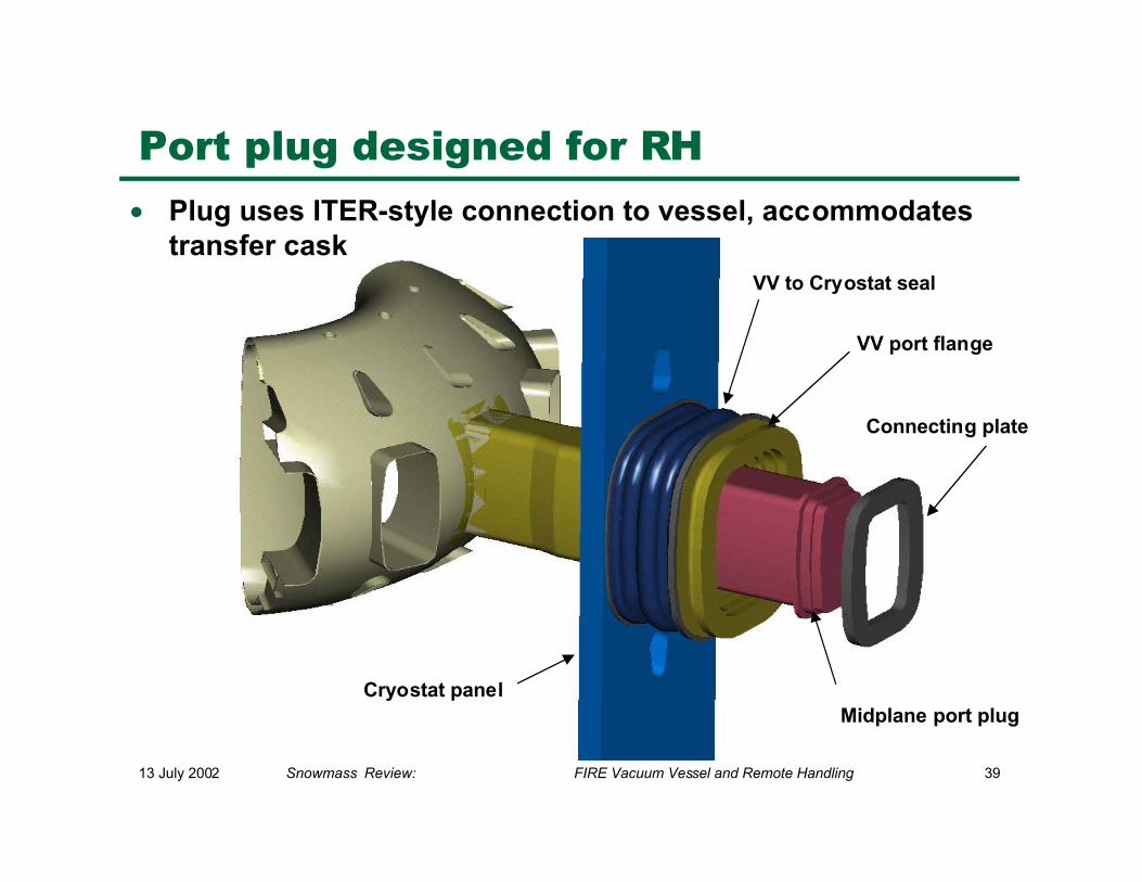
VV to Cryostat seal
VV port flange
Midplane port plug
Connecting plate
Cryostat panel
Port plug designed for RH
• Plug uses ITER-style connection to vessel, accommodatestransfer cask
13 July 2002 Snowmass Review: FIRE Vacuum Vessel and Remote Handling 40
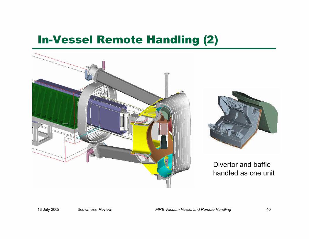
In-Vessel Remote Handling (2)
Divertor and bafflehandled as one unit
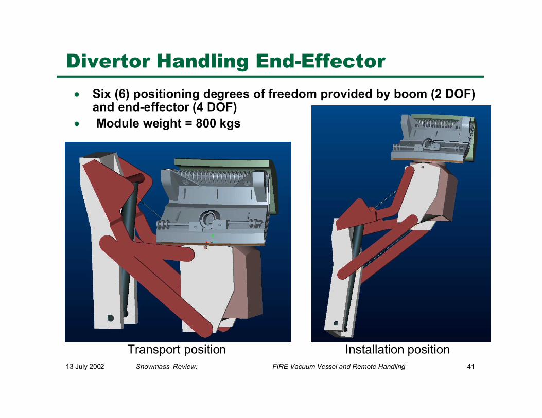
13 July 2002 Snowmass Review: FIRE Vacuum Vessel and Remote Handling 41
• Six (6) positioning degrees of freedom provided by boom (2 DOF)and end-effector (4 DOF)
• Module weight = 800 kgs
Divertor Handling End-Effector
Transport position Installation position
13 July 2002 Snowmass Review: FIRE Vacuum Vessel and Remote Handling 42
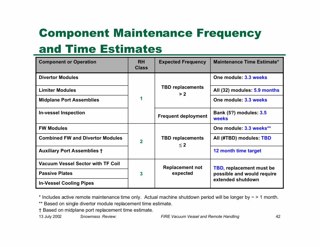
Component Maintenance Frequencyand Time Estimates
* Includes active remote maintenance time only. Actual machine shutdown period will be longer by ~ > 1 month.** Based on single divertor module replacement time estimate.† Based on midplane port replacement time estimate.
In-Vessel Cooling Pipes
Passive PlatesTBD, replacement must bepossible and would requireextended shutdown
Replacement notexpected3
Vacuum Vessel Sector with TF Coil
12 month time targetAuxiliary Port Assemblies †
All (#TBD) modules: TBDCombined FW and Divertor Modules
One module: 3.3 weeks**
TBD replacements
≤ 22
FW Modules
Bank (5?) modules: 3.5weeksFrequent deployment
In-vessel Inspection
One module: 3.3 weeksMidplane Port Assemblies
All (32) modules: 5.9 monthsLimiter Modules
One module: 3.3 weeks
TBD replacements
> 21
Divertor Modules
Maintenance Time Estimate*Expected FrequencyRHClass
Component or Operation
13 July 2002 Snowmass Review: FIRE Vacuum Vessel and Remote Handling 43
Remote Handling EquipmentSummary
• In-Vessel Component Handling System− In-vessel transporter (boom), viewing system and end-effectors (3) for:
divertor module, first wall / limiter module and general purpose manipulator
• In-Vessel Inspection System− Vacuum compatible metrology and viewing system probes for inspecting
PFC alignment, and erosion or general viewing of condition
− One of each probe type (metrology and viewing) initially procured
•• Port-Mounted Component Handling Systems
− Port assembly transporters (2) with viewing system and dexterousmanipulator for handling port attachment and vacuum lip-seal tools
− Includes midplane and auxiliary port handling systems
13 July 2002 Snowmass Review: FIRE Vacuum Vessel and Remote Handling 44
Remote Handling EquipmentSummary (2)
• Component & Equipment Containment and Transfer Devices− Cask containment enclosures (3) for IVT, midplane and auxiliary port− Double seal doors in casks with docking interfaces at ports and hot cell interfaces− Cask transport (overhead crane or air cushion vehicles TBD) and support systems− Portable shielded enclosure (1) for midplane port extended opening
• Remote Tooling− Laser based cutting, welding and inspection (leak detection) tools for:
• vacuum lip-seal at vessel port assemblies (2 sets)• divertor coolant pipes (1 set)
− limiter coolant pipes (1 set)
− Fastener torquing and runner tools (2 sets)
• Fire Site Mock-Up− Prototype remote handling systems used for developing designs are ultimately
used at FIRE site to test equipment modifications, procedures and train operators− Consists of prototypes of all major remote handling systems and component mock-
ups (provided by component design WBS)