m a n u s c r i p t - dlr portalelib.dlr.de/101167/1/15-08-28 paper zykla postprint including... ·...
TRANSCRIPT
1
M A N U S C R I P T
for publication in the
International Journal of Hydrogen Energy
Long-term cycle stability of metal hydride-graphite composites
Mila Dieterich1,*, Carsten Pohlmann2, Inga Bürger1, Marc Linder1 and Lars Röntzsch2,**
1 German Aerospace Center (DLR) - Institute of Engineering Thermodynamics,
Thermal Process Technology, Pfaffenwaldring 38 – 40, 70569 Stuttgart, Germany
2 Fraunhofer Institute for Manufacturing Technology and Advanced Materials (IFAM),
Branch Lab Dresden, Winterbergstraße 28, 01277 Dresden, Germany
*Corresponding author: phone: +49 (711) 6862-214; fax: +49 (711) 6862-632
e-mail: [email protected]
**Corresponding author: phone: +49 (351) 2537-411; fax: +49 (351) 2537-399
e-mail: [email protected]

2
Graphical Abstract
Abstract
Recently, metal hydride composites (MHC) have been proposed which consist of a hydride forming
metal alloy and a highly heat conduction secondary phase such as expanded natural graphite (ENG)
in order to improve the thermal conductivity of metal hydride powder beds. However, only little data
is available in the literature on the effects of extensive cycling on technically relevant properties of
MHC.
In this paper, hydrogenation characteristics, thermal conductivity and geometrical stability of
Hydralloy® C5-based MHC were thoroughly investigated over 1000 cycles. The obtained results
suggest that the MHC under study did not significantly alter their hydrogen uptake characteristics
throughout cycling, despite the fact that their thermal conductivity decreased during the first 250
cycles but remained constant thereafter. Although the cylindrical MHC maintained their geometrical
stability, radial cracks were detected after cycling. Based on these results, MHC are suitable for high-
dynamic applications such as hydrogen storage or thermochemical devices.
Keywords
metal hydride; Hydralloy® C5; metal hydride composites (MHC); heat transfer enhancement; cycle
stability;
Abbreviations
MHC – metal hydride composite
ENG – expanded natural graphite

3
Nomenclature
Δp differential pressure
T temperature
x hydrogen uptake
4
1 Introduction
One of the challenges of renewable energy sources is their volatility. Therefore, energy storage
technologies are essential in order to meet the actual energy demand. Surplus electricity, for
example, can be stored in form of hydrogen following the electrochemical splitting of water.
Hydrogen is a versatile secondary energy carrier that can be used in fuel cells, chemical synthesis or
combustion when needed. Metal hydrides are a promising option to store hydrogen at high
volumetric density, moderate temperatures and low pressures [1–4].
A specific example where metal hydrides can be used for energy storage refers to domestic
applications. Here, hydrogen produced by electrolysis using photovoltaic surplus energy can be
stored in a metal hydride. At a later stage, hydrogen is released from the metal hydride storage to
feed fuel cells to ensure uninterrupted energy supply [5]. Moreover, the heat of the corresponding
exothermal hydride formation (absorption) can be used for thermal applications, for example,
heating of domestic water. (See more in [6–8])
For such applications, in addition to a high hydrogen capacity and a high heat of reaction, the metal
hydride must also be able to fully absorb and/or desorb hydrogen quickly. Therefore, excellent heat
transfer characteristics through the hydride forming material are essential to remove or provide the
corresponding heat of reaction. Because metal hydride powders have low intrinsic thermal
conductivity [9,10] (in the order of 1 W∙m-1∙K-1 and less), the enhancement of the heat transfer
characteristics is necessary. In this regard, plenty of suggestions can be found in the literature [9,11–
15]. One of the possible solutions is to mix the hydride forming metal powder with expanded natural
graphite (ENG) and fabricate composites from these mixtures. This pathway has been studied for
high temperature metal hydrides in recent literature [10,16–18]. Using Hydralloy® C5, a Ti-Mn-base
alloy, Pohlmann et al. [19–21] introduced stable compacted metal hydride composites (MHC) with
high thermal conductivity for low temperature materials. In this case, the ENG forms a matrix within
the MHC, thus, enhancing the thermal conductivity and ensuring sufficient gas permeability at the
same time. Furthermore, it is assumed that the percolated ENG network stabilizes the whole MHC
5
structure. The compaction of hydride forming metal powders with ENG increases the thermal
conductivity by more than two orders of magnitude. However, the influence of prolonged cycling on
MHC stability, structure and hydrogenation performance has not yet been investigated.
Numerous papers report on the cycle stability of pure metal hydrides [22–28]. For example,
Friedlmeier et. al. [29] investigated an AB2 material (Ti0.98Zr0.02V0.43Fe0.09Cr0.05Mn1.5) very similar to
Hydralloy® C5 (Ti0.95 Zr0.05Mn1.55V0.45Fe0.09) used in this paper. Accordingly, no degradation was
identified after 42,400 cycles. With regard to the cycle stability of MHC, however, only little data is
available [30,31]. Therefore, we have performed intensive experimental studies on the cycling
stability of Hydralloy® C5-based MHC with respect to hydrogenation/dehydrogenation performance
as well as geometrical stability. Up to 1000 hydrogenation/dehydrogenation cycles were performed
using MHC with different ENG contents. In particular, temperature response, hydrogen uptake,
thermal conductivity and geometrical stability were investigated. In order to test several MHC in
parallel, a specific test rig was designed and brought into operation which allows fully automatic and
high-dynamic pressure-induced cycles at constant absorption and desorption pressures.
2 Research setting and methods
2.1. Hydralloy® C5-graphite composites
All MHC under investigation were fabricated using Hydralloy® C5 as hydride-forming metal alloy [19].
Hydralloy® C5 (51 wt.-% Mn, 28 wt.-% Ti, 14 wt.-% V, 3 wt.-% Fe, 3 wt.-% Zr) was purchased from GfE
Metalle und Materialien GmbH. The material was delivered in granular form and was milled for 5 min
under argon atmosphere. The received Hydralloy® C5 powder was thoroughly mixed with 10 ±
0.1 wt.-% ENG delivered by SGL Carbon. The metal powder-ENG blends were consolidated by uniaxial
compaction at 75 MPa into cylindrical MHC with 13.5 mm in diameter and a height of approximately
6.7 mm. Thereafter, a 2 mm central hole was drilled to ensure fast gas transport in axial direction.
The according residual porosity within the samples was calculated on the basis of the theoretical

6
density of each MHC using the theoretical density of ENG of about 2.1 g∙cm−3 and Hydralloy® C5 of
about 6.1 g∙cm-3 [19]. The radial effective thermal conductivities of selected MHC samples were
examined before and after cycling via the nano flash method applying a gas tight measuring cell. The
complete processing chain and analytic details are described in a previous work [32].
2.2. Test rig
2.2.1. Test rig layout
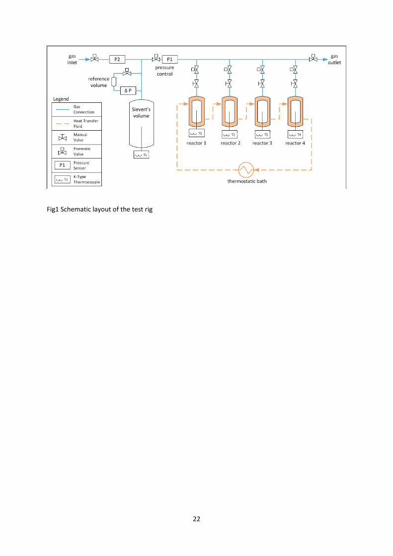
To investigate the long-term cycle stability of MHC, a special test rig was developed and brought into
operation. It enables us to control and monitor large quantities of up to the kilogram range of
reaction material for extensive number of cycles which allows the investigation of complete
structures, e.g. matrixes for heat transfer enhancement in metal hydride composites. Four parallel
test reactors with MHC samples can be monitored regarding their hydrogenation performance, MHC
sample temperature and gas uptake dynamics at the same time. In particular, the time-dependence
of these values during cycling is of interest. The test rig can be operated automatized at temperature
levels between 50 °C and 400 °C and at hydrogen pressures up to 100 bar. During cycling large
temperature changes inside the MHC occur which are tempered using a thermal fluid connected to a
thermostatic bath at constant temperature. The hydrogen gas pressure can be increased or
decreased quickly (in the order of seconds), thus, high-dynamic hydrogenation-dehydrogenation
tests can be conducted. A schematic layout of the test rig is depicted in Figure 1.
The temperature development within each MHC sample is monitored using a 1 mm thermocouple of
type K. The thermocouple is positioned in the middle of the MHC, as here the highest temperature
gradient is expected. Furthermore, the temperature within the heat transfer fluid is measured at
several positions with PT100 temperature sensors. The flow rate of the heat transfer fluid is set as
high as to guarantee a constant and almost identical (± 1 K) temperature for all reactors. The
hydrogen pressure inside the reactors is monitored using a pressure sensor (measuring accuracy:

7
uncertainty of measurement of ±0.6 bar, reproducibility of ±0.12 bar). The overall hydrogen uptake is
measured by an included Sievert’s apparatus, as explained in the following.
2.2.2. Determining the hydrogen uptake by Sieverts’ method
The Sieverts’ method is used here to determine the hydrogen uptake of the MHC and, more
importantly, to determine any changes in the hydrogen uptake as a function of the cycle number.
The method is also referred to as volumetry or manometry [33]. In general, the Sieverts’ apparatus
consists of a known volume (here called Sieverts’ volume including all tubing, 𝑉𝑉𝑆𝑆𝑆𝑆𝑆𝑆𝑆𝑆𝑆𝑆𝑆𝑆𝑆𝑆𝑆𝑆′) filled with
hydrogen and a pressure sensor. The measured pressure drop is directly correlated to the mass of
hydrogen leaving the Sieverts’ volume. In the present configuration, the Sieverts´ volume and the
volume of the four test reactors are separated by a control valve. Therefore, the pressure in the
reactors can be controlled at a set point, which is kept constant throughout absorption independent
of the amount of absorbed hydrogen and of the pressure in the Sieverts’ volume. The absorption
pressure can be set between 1 bar and 100 bar.
All instruments used in the present setup are calibrated by the manufacturers. Data transmission
errors are corrected. For the present set-up with pressures up to 70 bar, the error in mass due to the
compressibility of hydrogen (3.4% at 25°C [34]) is neglected. A detailed guideline for an accurate
measurement is given in Broom et al. [28]. However, since the aim of these measurements is neither
the determination of thermodynamic or kinetic properties of the pure material nor the operation
below atmospheric pressure the aspects that need to be considered are reduced to the following two
points: Accuracy of pressure measurement and free volume correction.
Accuracy of pressure measurement
To realize a high accuracy of the pressure measurement even at high absorption pressures, a
differential pressure sensor (ΔP) and a small reference volume are added to the apparatus (cf. Figure
1). By separating this volume at initial pressure, the pressure change in the Sieverts’ volume is

8
measured during the experiments. Thereby, a high accuracy of 0.05 bar for pressure differences up
to 10 bar can be achieved. The measurement range of the used pressure sensor enables the
measurement of a wide range of materials with different hydrogen storage capacities and densities.
Thus, it also allows a sufficient accuracy for the measurements, especially with a focus on cycling
stability. For higher pressure differences, the pressure of the Sieverts’ volume is measured directly by
an absolute-pressure sensor (P2) with an accuracy of 0.8 bar up to 100 bar. For the measurements in
this study, the sample size was chosen to cause a pressure difference of less than 10 bar in the
Sieverts’ volume to gain high accuracy.
Free volume correction
For absorption, the volume of the tubing, reactors, and porosity of the material is filled with
hydrogen which is not absorbed but causes a pressure drop in the Sieverts’ volume. Therefore, a
correction of this free volume is needed as described by Rouquerol in [35].
The free volume varies during cycling due to the volume changes of the metal hydride during
absorption and desorption. The calculation of the volume-mass relationship given by Wang and Suda
[36] showed that the system volume is big enough compared to the MHC mass and, therefore, the
volume change of material during cycling and, thus, the change of the free volume is insignificant.
The free volume was measured at low pressures, where hydrogen is assumed to behave as an ideal
gas. The duration of measurement was long enough for all temperatures to return to their initial
values. For the measurement, absorption has to be excluded. This can be achieved, depending on the
material, either by measuring at a different temperature, with an inert gas, before activation or
without the material. The transfer to the experiment for the first two options can be calculated with
the ideal gas law including reality factors if necessary. If measuring without material its volume
calculated from its mass and density has to be considered (see Appendix). Because Hydralloy® C5 is
very reactive, we chose to measure without material. From the ideal gas law, the pressure drop with
material can be calculated. See the Appendix for more detail.

9
Calculation of hydrogen uptake
The mass of hydrogen absorbed can then be determined with the ideal gas law. Knowing the mass of
the metal hydride in the MHC, the hydrogen uptake can be calculated.
Concluding this section, it has to be noted that the determined reversible hydrogen uptake is subject
to errors, as mentioned before. However, the intention of the present setup is the investigation of
changes in this value as a function of the number of cycles. As the reproducibility of all values is very
high, such changes can be determined accurately and, therefore, give important information about
possible degradation of the MHCs.
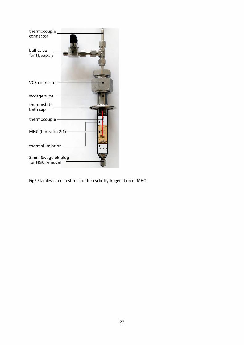
2.2.3. Test reactors
Four equally sized cylindrical test reactors made from stainless steel with an inner diameter of
13.5 mm were placed in containers connected with the thermostatic bath. Each of the test reactors
was filled with four MHC bodies (pellets) with a total height of about 27 mm (height-diameter-ratio
of 2:1) in-between two cylindrical pieces of teflon (each with a height of 13.5 mm) to ensure thermal
insulation in axial direction (cf. Figure 2). The thermal insulation in axial direction was included in
order to be able to focus mainly on the thermal conductivity of the MHC in radial direction. It can be
excluded that teflon chemically interferes with the hydrogen uptake of the MHC under study. The
axial position of the thermocouple within the MHC was set to approximately half of the total MHC
height.
2.2.4. Testing procedure
The MHC samples were activated and cycled with hydrogen of 99.999 % purity. First, the MHC were
activated by applying two cycles of 2 h at 130 °C and hydrogen pressure at 5 bar and vacuum,
respectively, and one cycle at 50 °C and hydrogen pressure at 30 bar for 13 h and vacuum for half an

10
hour, respectively. Then, the MHCs were cycled at a constant temperature of 50 °C. The absorption
pressure was set to 40 bar and desorption pressure to 1 bar. Both absorption and desorption took
place very quickly (in the order of 2 to 5 min) leading to a significant change in MHC temperature. A
change in this peak temperature during cycling has been used as one indication for a change in
thermal conductivity.
2.3. MHC geometrical stability after cycling
After cycling, the reactors were opened under inert atmosphere in order to extract the MHC. A 3 mm
Swagelok connector at the bottom of the reactors (cf. Figure 2) can be opened to push the MHC.
However, due to a slight volume swelling of the MHC due to cycling, an intimate contact between the
MHC and the inner reactor walls was observed which increased wall friction drastically. Therefore, in
many cases the MHC were damaged during removal (fractures, deformations and break-offs of the
MHC). Thus, only a qualitative impression of the geometrical stability can be given.

11
3 Results and discussion
In the present paper, the hydrogenation properties and geometrical stability of Hydralloy® C5-based
MHC were investigated. For this purpose, identical MHC with an ENG-content of 10 wt.-% and a
residual porosity of approx. 30 % were fabricated. At first, a cycling time of 10 minutes (5 min
absorption + 5 min desorption) was applied for 1000 cycles. The hydrogenation/dehydrogenation
performance was observed throughout cycling, whereas the mechanical stability and thermal
conductivity were determined after 250, 500, 750, and 1000 cycles by stepwise removing the MHC
bodies (pellets) from the four identical reactors.
The applied cycling time of only 10 minutes seemed to have an influence on the development of
hydrogen uptake. Therefore, another identical MHC was cycled with a longer cycling time of
60 minutes (30 min absorption + 30 min desorption) for only 100 cycles. Again, hydrogenation
performance and mechanical stability after 100 cycles were determined.
3.1. Cycling stability of hydrogenation performance
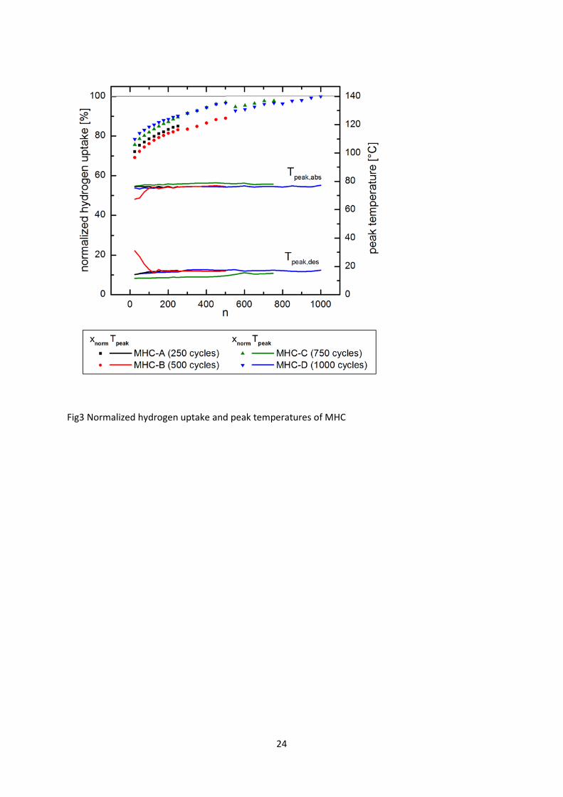
The relative amounts of absorbed hydrogen (hydrogen uptake) of MHC are presented in Figure 3. To
compare the four samples, their hydrogen capacity was normalized to the maximum hydrogen
capacity of sample MHC-D after 1000 cycles which corresponds to approximately 1.5 wt.-%.
Furthermore, the maximum temperatures of the MHC samples during absorption (Tpeak,abs) and the
minimum temperatures during desorption (Tpeak,des) are plotted. From these curves, the following
conclusions can be drawn:
First, it can be seen that the hydrogen capacity after 5 min of absorption (hydrogen uptake) increases
with increasing cycle number starting from about 70 % of the nominal capacity. All MHC samples
follow the same trend. After 600 cycles, the full hydrogen capacity is reached. The hydrogen uptake
never declines compared to the prior cycle (see absolute values in Figure 3) except for cycle 550.
Before this cycle, the test bench had to be modified and the MHCs were stored at room temperature
in hydrogen at desorption pressure for four weeks. The effect is clearly visible as a decrease in
12
hydrogen uptake compared to before. Thus, in view of hydrogen uptake, the prepared MHC exhibit a
stable cycling behavior over 1000 cycles.
Second, the peak temperatures of all MHC samples are on the same quantitative level throughout all
cycles. According to Figure 3, a slight deviation is observed for sample MHC-B where the peak
temperatures are about 10 K closer to the temperature of the thermostatic bath for the first 120
cycles. Afterwards, the temperature signals are very similar to the other MHC samples. This deviation
might be caused by slight sample displacements relative to the thermocouple due to sample
transport. Nevertheless, regarding the peak temperatures during absorption and desorption, it is
legitimate to state that the MHC exhibit a stable hydrogenation performance over 1000 cycles.
In order to discuss the cycle-dependent hydrogen uptake dynamics of MHC in more detail, Figure 4
presents the temperature development at the center of the MHC (straight lines) and the corrected
differential hydrogen pressure development (dashed lines) after the 25th, 50th, 250th, 500th, 750th, and
1000th cycle. Furthermore, an inset provides the total hydrogen uptake after the respective cycle.
The curves of the differential pressure show a very steep increase within the first 20 s of a cycle;
afterwards a slight decrease is recognizable before the curves increase again to their maximum
values. The slight decrease might be explained by artefacts of the pressure measurement, which
occur when the rapidly flowing hydrogen vigorously pulls at the membrane of the pressure sensor.
Therefore, the differential pressure curve does not represent the precise course of the hydrogen
uptake. Thus, only the maximum values of hydrogen uptake for each cycle are given. The results
illustrate the steady increase in hydrogen capacity up to 1.54 wt.-% for the 1000th cycle.
Figure 4 also demonstrates that the temperature profiles of the MHC are nearly equal for all cycles.
As the hydrogen uptake of Hydralloy C5 is very sensible to temperature [37], the increase in
temperature during absorption limits the hydrogen uptake. Therefore, during cooling more hydrogen
can be absorbed and heat is released leading to a slower decline of the temperature. As soon as the
hydrogenation reaction is almost finished, the temperature decreases faster. This rapid cooling can
13
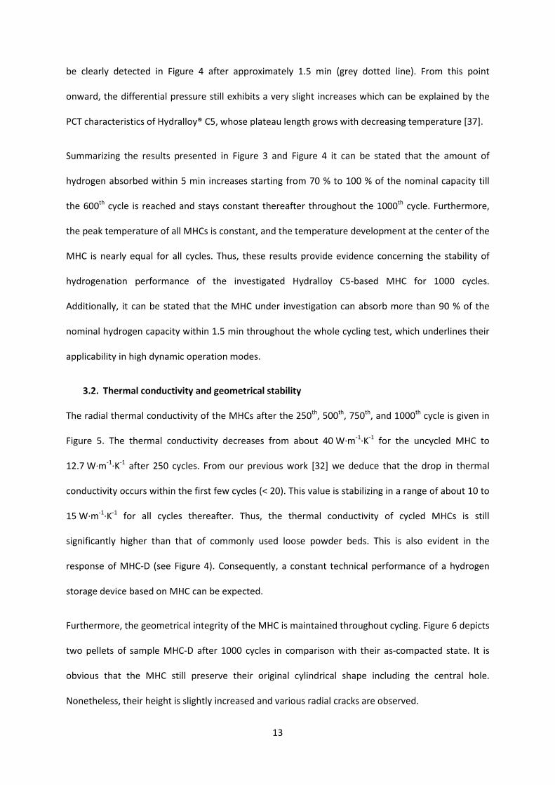
be clearly detected in Figure 4 after approximately 1.5 min (grey dotted line). From this point
onward, the differential pressure still exhibits a very slight increases which can be explained by the
PCT characteristics of Hydralloy® C5, whose plateau length grows with decreasing temperature [37].
Summarizing the results presented in Figure 3 and Figure 4 it can be stated that the amount of
hydrogen absorbed within 5 min increases starting from 70 % to 100 % of the nominal capacity till
the 600th cycle is reached and stays constant thereafter throughout the 1000th cycle. Furthermore,
the peak temperature of all MHCs is constant, and the temperature development at the center of the
MHC is nearly equal for all cycles. Thus, these results provide evidence concerning the stability of
hydrogenation performance of the investigated Hydralloy C5-based MHC for 1000 cycles.
Additionally, it can be stated that the MHC under investigation can absorb more than 90 % of the
nominal hydrogen capacity within 1.5 min throughout the whole cycling test, which underlines their
applicability in high dynamic operation modes.
3.2. Thermal conductivity and geometrical stability
The radial thermal conductivity of the MHCs after the 250th, 500th, 750th, and 1000th cycle is given in
Figure 5. The thermal conductivity decreases from about 40 W∙m-1∙K-1 for the uncycled MHC to
12.7 W∙m-1∙K-1 after 250 cycles. From our previous work [32] we deduce that the drop in thermal
conductivity occurs within the first few cycles (< 20). This value is stabilizing in a range of about 10 to
15 W∙m-1∙K-1 for all cycles thereafter. Thus, the thermal conductivity of cycled MHCs is still
significantly higher than that of commonly used loose powder beds. This is also evident in the
response of MHC-D (see Figure 4). Consequently, a constant technical performance of a hydrogen
storage device based on MHC can be expected.
Furthermore, the geometrical integrity of the MHC is maintained throughout cycling. Figure 6 depicts
two pellets of sample MHC-D after 1000 cycles in comparison with their as-compacted state. It is
obvious that the MHC still preserve their original cylindrical shape including the central hole.
Nonetheless, their height is slightly increased and various radial cracks are observed.

14
However, a strong stability within the radial planes can be deduced. Thus, the fast radial heat
transfer is preserved which can be seen in the measured thermal conductivities as well as in the
hydrogenation performance that allowed fast cycling throughout all 1000 cycles.
In this case, the MHC were not constrained regarding their axial expansion during cycling. If they had
been axially confined, an even more stable and more dynamic MHC would have resulted. However,
additional mechanical forces acting upon the tank wall, which are attributed to the MHC volume
swelling, would have evolved during hydrogen uptake.
3.3. Extension of cycling time
As mentioned in Section 3.1, the duration of hydrogen absorption seemed to have an influence on
the activation of the materials: When cycled at short cycle times of 10 min, the amount of hydrogen
uptake increases for approximately 600 cycles before it remained constant thereafter. In order to
test whether a longer cycling time would reduce the number of cycles before the maximum
hydrogen uptake is reached, one MHC was cycled over 60 min (30 min absorption + 30 min
desorption), the results of which are presented in Figure 7. Similarly to the short cycle time an
increase in hydrogen uptake is noticeable, however, on a higher relative level. Already after the 93rd
cycle the amount of hydrogen uptake equals that of the 1000th cycle when a short cycling time was
applied (cf. Figure 4). In both cases, the total absorption time adds up to the same value of 3000 min:
600 cycles with 5 min absorption and 100 cycles with 30 min absorption. Therefore, it is obvious that
absorption time has an influence on hydrogen uptake, however, it is not completely clear which one
is the main effect: the absorption time per cycle or the total absorption time.

15
4 Conclusion
This paper reports on the hydrogenation performance, thermal conductivity and the mechanical
stability of Hydralloy® C5-based MHCs with an ENG-content of 10 wt.-% throughout 1000 cycles. The
MHC showed constant temperature responses and increasing or constant hydrogen uptake
throughout all 1000 cycles. The thermal conductivity decreased after the first 250 cycles but was
constant afterwards in a range of about 10 to 15 W∙m-1∙K-1. Furthermore, after removing the MHC
from the reactors they still showed high geometrical stability, both of which leads to stable and
highly dynamic loading and unloading performance with a hydrogen uptake time of about 1.5
minutes. Additionally, the influence of the cycle time on the activation process was demonstrated.
Based on these results, Hydralloy® C5-based MHC can be considered suitable for various technical
applications.
Acknowledgement
This work is financially supported by the German Federal Ministry of Education and Research (BMBF)
within the project “Highly Dynamic Hydride-Graphite Composites (HD-HGV)” (project number
03EK3020).

16
References
[1] Sandrock G, Suda S, Schlapbach L. Applications. In: Schlapbach L, editor. Hydrog. Intermet. Comounds II - Surf. Dyn. Prop. Appl., Springer-Verlag; 1992, p. 197–258. doi:10.1007/3-540-54668-5.
[2] Botzung M, Chaudourne S, Gillia O, Perret C, Latroche M, Percheron-Guegan A, et al. Simulation and experimental validation of a hydrogen storage tank with metal hydrides. Int J Hydrogen Energy 2008;33:98–104. doi:10.1016/j.ijhydene.2007.08.030.
[3] Züttel A. Hydrogen storage methods. Naturwissenschaften 2004;91:157–72. doi:10.1007/s00114-004-0516-x.
[4] Utz I, Linder M, Schmidt N, Hu JJ, Fichtner M, Wörner A. Experimental study of powder bed behavior of sodium alanate in a lab-scale H2 storage tank with flow-through mode. Int J Hydrogen Energy 2012;37:7645–53. doi:10.1016/j.ijhydene.2012.02.016.
[5] Maeda T, Fuura T, Matsumoto I, Kawakami Y, Masuda M. Cyclic stability test of AB2 type (Ti, Zr)(Ni, Mn, V, Fe)2.18 for stationary hydrogen storage in water contaminated hydrogen. J Alloys Compd 2013;580:S255–8. doi:10.1016/j.jallcom.2013.03.230.
[6] Young K, Hills R. Metal Hydrides. Elsevier Inc.; 2013. doi:10.1016/B978-0-12-409547-2.05894-7.
[7] Bhuiya MMH, Kumar A, Kim KJ. Metal hydrides in engineering systems, processes, and devices: A review of non-storage applications. Int J Hydrogen Energy 2015. doi:10.1016/j.ijhydene.2014.12.009.
[8] Muthukumar P, Groll M. Metal hydride based heating and cooling systems: A review. Int J Hydrogen Energy 2010;35:3817–31. doi:10.1016/j.ijhydene.2010.01.115.
[9] Kim KJ, Montoya B, Razani A, Lee K-H. Metal hydride compacts of improved thermal conductivity. Int J Hydrogen Energy 2001;26:609–13. doi:10.1016/S0360-3199(00)00115-4.
[10] Chaise a., de Rango P, Marty P, Fruchart D. Experimental and numerical study of a magnesium hydride tank. Int J Hydrogen Energy 2010;35:6311–22. doi:10.1016/j.ijhydene.2010.03.057.
[11] Anbarasu S, Muthukumar P, Mishra SC. Tests on LmNi4.91Sn0.15 based solid state hydrogen storage device with embedded cooling tubes – Part A: Absorption process. Int J Hydrogen Energy 2014. doi:10.1016/j.ijhydene.2013.12.090.
[12] Meng X, Wu Z, Bao Z, Yang F, Zhang Z. Performance simulation and experimental confirmation of a mini-channel metal hydrides reactor. Int J Hydrogen Energy 2013:1–12. doi:10.1016/j.ijhydene.2013.09.056.
[13] Dehouche Z, de Jong W, Willers E, Isselhorst A, Groll M. Modelling and simulation of heating/air-conditioning systems using the multi-hydride-thermal-wave concept. Appl Therm Eng 1998;18:457–80. doi:10.1016/S1359-4311(97)00043-4.
[14] Rodríguez Sánchez A, Klein H-P, Groll M. Expanded graphite as heat transfer matrix in metal hydride beds. Int J Hydrogen Energy 2003;28:515–27. doi:10.1016/S0360-3199(02)00057-5.
17
[15] Kim J-H, Kim J-H, Hwang K-T, Kang Y-M. Hydrogen storage in magnesium based-composite hydride through hydriding combustion synthesis. Int J Hydrogen Energy 2010;35:9641–5. doi:10.1016/j.ijhydene.2010.06.099.
[16] Jehan M, Fruchart D. McPhy-Energy’s proposal for solid state hydrogen storage materials and systems. J Alloys Compd 2013;580:S343–8. doi:10.1016/j.jallcom.2013.03.266.
[17] Chaise a., de Rango P, Marty P, Fruchart D, Miraglia S, Olivès R, et al. Enhancement of hydrogen sorption in magnesium hydride using expanded natural graphite. Int J Hydrogen Energy 2009;34:8589–96. doi:10.1016/j.ijhydene.2009.07.112.
[18] Van Hassel B a., Mosher D, Pasini JM, Gorbounov M, Holowczak J, Tang X, et al. Engineering improvement of NaAlH4 system. Int J Hydrogen Energy 2012;37:2756–66. doi:10.1016/j.ijhydene.2011.02.005.
[19] Pohlmann C, Röntzsch L, Weißgärber T, Kieback B. Heat and gas transport properties in pelletized hydride–graphite-composites for hydrogen storage applications. Int J Hydrogen Energy 2013;38:1685–91. doi:10.1016/j.ijhydene.2012.09.159.
[20] Heubner F, Pohlmann C, Mauermann S, Kieback B, Röntzsch L. Mechanical stresses originating from metal hydride composites during cyclic hydrogenation. Int J Hydrogen Energy 2015;40:10123–30. doi:10.1016/j.ijhydene.2015.06.053.
[21] Herbrig K, Pohlmann C, Gondek Ł, Figiel H, Kardjilov N, Hilger A, et al. Investigations of the structural stability of metal hydride composites by in-situ neutron imaging. J Power Sources 2015;293:109–18. doi:10.1016/j.jpowsour.2015.05.039.
[22] Wanner M, Friedlmeier G, Hoffmann G, Groll M. Thermodynamic and structural changes of various intermetallic compounds during extended cycling in closed systems. J Alloys Compd 1997;253-254:692–7. doi:10.1016/S0925-8388(96)03041-1.
[23] Lambert SW, Chandra D, Cathey WN, Lynch FE, Bowman RC. Investigation of hydriding properties of LaNi4.8Sn0.2, LaNi4.27Sn0.24 and La0.9Gd0.1Ni5 after thermal cycling and aging. J Alloys Compd 1992;187:113–35. doi:10.1016/0925-8388(92)90527-G.
[24] Bowman RC, Luo CH, Ahn CC, Witham CK, Fultz B. The effect of tin on the degradation of LaNi5−ySny metal hydrides during thermal cycling. J Alloys Compd 1995;217:185–92. doi:10.1016/0925-8388(94)01337-3.
[25] Bershadsky E, Josephy Y, Ron M. Investigation of kinetics and structural changes in TiFe0.8 Ni0.2 after prolonged cycling. J Less Common Met 1991;172-174:1036–43. doi:10.1016/S0022-5088(06)80009-3.
[26] Dehouche Z, Djaozandry R, Huot J, Boily S, Goyette J, Bose T., et al. Influence of cycling on the thermodynamic and structure properties of nanocrystalline magnesium based hydride. J Alloys Compd 2000;305:264–71. doi:10.1016/S0925-8388(00)00718-0.
[27] Lototskyy MV, Yartys VA, Pollet BG, Bowman RC. Metal hydride hydrogen compressors: A review. Int J Hydrogen Energy 2014;39:5818–51. doi:10.1016/j.ijhydene.2014.01.158.
[28] Josephy Y, Bershadsky E, Ron M. Investigation of LaNi5 after prolonged cycling. J Less Common Met 1991;172-174:997–1008. doi:10.1016/S0022-5088(06)80005-6.

18
[29] Friedlmeier G, Manthey A, Wanner M, Groll M. Cyclic stability of various application-relevant metal hydrides. J Alloys Compd 1995;231:880–7. doi:10.1016/0925-8388(95)01776-3.
[30] Josephy Y, Eisenberg Y, Perez S, Ben-David A, Ron M. Hydrogen and thermal yields of porous metal matrix hydride compacts of MmNi4.15Fe0.85Hx. J Less Common Met 1984;104:297–305. doi:10.1016/0022-5088(84)90414-4.
[31] Ron M, Bershadsky E, Joseph Y. Thermal conductivity of PMH compacts, measurements and evaluation. Int J Hydrogen Energy 1992;17:623–30. doi:10.1016/0360-3199(92)90076-9.
[32] Pohlmann C, Röntzsch L, Heubner F, Weißgärber T, Kieback B. Solid-state hydrogen storage in Hydralloy–graphite composites. J Power Sources 2013;231:97–105. doi:10.1016/j.jpowsour.2012.12.044.
[33] Broom D. The accuracy of hydrogen sorption measurements on potential storage materials. Int J Hydrogen Energy 2007;32:4871–88. doi:10.1016/j.ijhydene.2007.07.056.
[34] US Department of Commerce N. National Institute of Standards and Technology n.d. http://www.nist.gov/ (accessed August 13, 2015).
[35] Rouquerol F, Rouquerol J, Sing K. Adsorption by Powders and Porous Solids. Elsevier; 1999. doi:10.1016/B978-012598920-6/50004-X.
[36] Wang X-L, Suda S. Consistent determination of the intrinsic kinetic properties between hydrogen and hydriding alloys. J Alloys Compd 1995;231:660–5. doi:10.1016/0925-8388(95)01748-8.
[37] Herbrig K, Röntzsch L, Pohlmann C, Weißgärber T, Kieback B. Hydrogen storage systems based on hydride–graphite composites: computer simulation and experimental validation. Int J Hydrogen Energy 2013;38:7026–36. doi:10.1016/j.ijhydene.2013.03.104.
19
List of figures
Figure 1: Schematic layout of the test rig with four test reactors and a Sievert’s volume.
Figure 2: Stainless steel test reactor for cyclic hydrogenation of MHC
Figure 3: Normalized hydrogen uptake and peak temperatures of MHC at a cycle time of 10 min (5 min absorption + 5 min desorption).
Figure 4: Temperature T, corrected differential pressure Δp and hydrogen uptake x
Figure 5: Development of the radial thermal conductivity of MHC throughout 1000 cycles.
Figure 6: Sample MHC-D before (small picture) and after (large picture) 1000 cycles.
Figure 7: Corrected differential pressure and hydrogen uptake of a MHC for a cycle time of 60 minutes.

20
Appendix: Details to free volume correction
The free volume 𝑉𝑉𝑓𝑓𝑆𝑆𝑆𝑆𝑆𝑆 is calculated by 𝑉𝑉𝑓𝑓𝑆𝑆𝑆𝑆𝑆𝑆 = ∆𝑝𝑝𝑆𝑆𝑆𝑆𝑆𝑆𝑆𝑆𝑆𝑆𝑆𝑆𝑆𝑆𝑆𝑆′ 𝑉𝑉𝑆𝑆𝑆𝑆𝑆𝑆𝑆𝑆𝑆𝑆𝑆𝑆𝑆𝑆𝑆𝑆′ 𝑇𝑇𝑆𝑆𝑆𝑆𝑟𝑟𝑟𝑟𝑆𝑆𝑡𝑡𝑆𝑆∆𝑝𝑝𝑆𝑆𝑆𝑆𝑟𝑟𝑟𝑟𝑆𝑆𝑡𝑡𝑆𝑆 𝑇𝑇𝑆𝑆𝑆𝑆𝑆𝑆𝑆𝑆𝑆𝑆𝑆𝑆𝑆𝑆𝑆𝑆′
− 𝑉𝑉𝑀𝑀𝑀𝑀𝑀𝑀, where ∆𝑝𝑝𝑆𝑆𝑆𝑆𝑆𝑆𝑆𝑆𝑆𝑆𝑆𝑆𝑆𝑆𝑆𝑆′
is the pressure drop in the Sieverts’ volume due to absorption, ∆𝑝𝑝𝑆𝑆𝑆𝑆𝑟𝑟𝑟𝑟𝑆𝑆𝑟𝑟𝑆𝑆 is the pressure increase in
the reactor, 𝑇𝑇𝑆𝑆𝑆𝑆𝑆𝑆𝑆𝑆𝑆𝑆𝑆𝑆𝑆𝑆𝑆𝑆′ and 𝑇𝑇𝑆𝑆𝑆𝑆𝑟𝑟𝑟𝑟𝑆𝑆𝑟𝑟𝑆𝑆 are the absolute temperatures in the Sieverts’ volume and the
reactor, respectively, and 𝑉𝑉𝑀𝑀𝑀𝑀𝑀𝑀 is the volume of the MHC. The latter is calculated from the mass and
density of the material. For the present setup, the biggest influence on the accuracy of the free
volume has been by far the measurement of the pressure differences. This is because of the small
changes in pressure when no reaction takes place, hence, the difference of the measured values is
close to the value of accuracy.
The pressure drop in the Sieverts’ volume caused by the free space ∆𝑝𝑝𝑆𝑆𝑆𝑆𝑆𝑆𝑆𝑆𝑆𝑆𝑆𝑆𝑆𝑆𝑆𝑆′𝑓𝑓𝑆𝑆𝑆𝑆𝑆𝑆 can be calculated
for cycling conditions by ∆𝑝𝑝𝑆𝑆𝑆𝑆𝑆𝑆𝑆𝑆𝑆𝑆𝑆𝑆𝑆𝑆𝑆𝑆′𝑓𝑓𝑆𝑆𝑆𝑆𝑆𝑆 = ∆𝑝𝑝𝑆𝑆𝑆𝑆𝑟𝑟𝑟𝑟𝑆𝑆𝑡𝑡𝑆𝑆 𝑉𝑉𝑓𝑓𝑆𝑆𝑆𝑆𝑆𝑆 𝑇𝑇𝑆𝑆𝑆𝑆𝑆𝑆𝑆𝑆𝑆𝑆𝑆𝑆𝑆𝑆𝑆𝑆′𝑇𝑇𝑆𝑆𝑆𝑆𝑟𝑟𝑟𝑟𝑆𝑆𝑡𝑡𝑆𝑆 𝑉𝑉𝑆𝑆𝑆𝑆𝑆𝑆𝑆𝑆𝑆𝑆𝑆𝑆𝑆𝑆𝑆𝑆′
. Here, the determination of the
free volume has the biggest influence on the accuracy.

21
Figures
Graphical Abstract
22
Fig1 Schematic layout of the test rig
23
Fig2 Stainless steel test reactor for cyclic hydrogenation of MHC
24
Fig3 Normalized hydrogen uptake and peak temperatures of MHC

25
Fig4 Temperature T, corrected differential pressure Δp

26
Fig5 Development of the radial thermal conductivity of MHC

27
Fig6 Sample MHC-D before and after 1000 cycles

28
Fig7 Corrected differential pressure and hydrogen uptake