lxt1001 network controller - freebsdwpaul/level1/lxt1001srm.pdf · the lxt1001 network controller...
TRANSCRIPT
Document #: IS1001SROrig. Date: 8/24/98Revision #: 1.0Rev. Date: 7/9/99
l
LXT1001 Network Controller
Order NumberLXT1001SW/D
Rev. 1.0 July 9, 1999
ADVANCE INFORMATIONSoftware Manual
l

l
Features (cont.)

LXT1001Software Reference Manual
7/99Product Specification - Advance Information
Document #: IS1001SROrig. Date: 8/24/98Revision #: 1.0Rev. Date: 7/9/99
Revision 1.0
L
General Description FeaturesThe LXT1001 10/100/1000 Mbps Ethernet controllerprovides the optimal combination of cost and system-levelperformance for network interface connections in serverplatforms and high-performance workstations.
The LXT1001 network controller is the first in a family ofhigh-performance network accelerators by Level OneCommunications designed to meet the needs of high-speednetwork equipment. The LXT1001 incorporates a10/100/1000 Mbps 802.3-compliant Media AccessController (MAC) with extensive packet buffering and anoptimized 64-bit PCI system interface. The LXT1001MAC increases system performance by includinghigh-level functions (e.g., VLAN filtering and IP packetprocessing) in the hardware. The PCI system interface usesthe patent-pending Level One CommunicationsPropulsion algorithms to achieve dramatic increases insystem throughput.
• Support 10, 100 and 1000 Mbps Ethernet
• Deep, independent, on-board receive (RX) and transmit (TX) FIFOs
• Peripheral Component Interconnect (PCI) v2.2 compliant interface supporting operation up to 33 MHz with a 64-bit wide data path
• Three data transfer methods: Programmed I/O (PIO); Packet Descriptor List (PDL); and Propulsion Packet Descriptor Command (PDC)
• Full- and half-duplex operation, including carrier extension and packet bursting in half-duplex 1000 Mbps operation
• Symmetric and asymmetric flow control
• Supports MII, GMII, and TBI
• 272-pin Plastic Ball Grid Array (PBGA) package
• Commercial Temp Range (0–70 ºC)
LXT1001 Controller
LEDInterface
SerialEEPROMInterface
Boot ROMInterface
ControlRegisters
PCI B
us In
terfa
ce
Bus MasterController
DescriptorRAM
IEEEI149.1JTAGPort
MAC
MACControl
VLAN
PhysicalLayer
Interface
GMIIor
PCS
Phys
ical
Lay
er D
evic
e
Physical Interface
System Interface
MAC
8
8
8
8 64
64
PCI B
us
TX FIFO
RX FIFO
Data Buffers
TCPIPChecksum
Verifier8
2l
LXT1001 Network ControllerAdditional LXT1001 Features
Document #: IS1001SROrig. Date: 8/24/98
Revision #: 1.0Rev. Date: 7/9/99
Features (cont.)
ADDITIONAL LXT1001 FEATURES
Robust Drivers and ManagementSupporting software includes certified device driversand end user diagnostics.
• Windows® NT 3.51, 4.0 and 5.0; Windows® 95OSR2; Windows ® 98; NetWare™ 3.12, 3.2, 4.2,4.11 and 5.0; and Linux 2.0 and 2.2
• Support for the OnNow Initiative and PCI PowerManagement
- Wake-on-LAN™ , Magic Packet™ in PC1Power Managed systems
- PCI PME Signal
• Required elements of the 802.3 MIB
Optimized Bus Transfer Operation• High-Speed PCI Interface
• PCI 2.2 compliant
• Efficient PCI master operation
• 33MHz, 32-/64-bit operation
• 64-bit addressing
• Supports dual address cycles
• Supports three I/O methods
• Programmed I/O
• Traditional scatter-gather “bus master” DMA
• Propulsion™ technology — packet burstingacross PCI bus increases the throughput for smallpackets
• Propulsion features
• Packet bursting across PCI bus
• Minimizes bus arbitrations
• Eliminates logical to physical address translation
• Scales to wider bus widths and faster clock rates
• Minimizes interrupts by coalescing transfersacross the PCI bus
Expansion/Convenience Features• EEPROM Interface
• Single word read/writes or reads entire contents
• Checksum after read, auto-detection
• Expansion ROM Interface
- Supports ROM, EPROM, and Flash memory
- Internally supports up to 4K expansion ROM
- Up to one megabyte can be supported usingexternal logic
• Supports up to four individually programmable LEDs
• IEEE 1149.1a-1993 (JTAG)-compliant boundary scan
Technology Features• State machine design
• 0.35 micron process
• Plastic Ball Grid Array (PBGA) package
• 3.3-volt/5-volt-tolerant I/Os
• Targeted power consumption of less than 1.5W(typical)
Host Offloading and Policy-Based Behavior• IPv4 checksum calculation on chip
• IP, TCP and UDP checksums supported
• Packet filtering based on checksum errors
• 802.3ac and VLAN tag support
• Programmable 16-entry table; Filtering based onrecognized VLANs; VLAN tag stripping onreceive; Global and/or per packet VLAN taginsertion on transmit
3
LXT1001 Network ControllerTable of Contents
Document #: IS1001SROrig. Date: 8/24/98Revision #: 1.0Rev. Date: 7/9/99
l
TABLE OF CONTENTS
SECTION 1 TYPES OF REGISTERS..............7SECTION 2 THEORY OF OPERATIONS........9
Input/Output Methods .........................................9Programmed Input/Output ..............................9Packet Descriptor List .....................................9Packet Propulsion Method (PacketDescriptor Command) ...................................12
Organization ......................................................16Initialization ......................................................17
Reset ..............................................................17Physical Layer Configuration and Status ......17PDC Buffer Allocation .................................18PDL Buffer Allocation ..................................18System Initialization Event Sequence ...........18Initialization Algorithm ................................18
Transmit Packet Processing ..............................23Transmit Packet Padding ..............................23VLAN Tag Header Insertion ........................23CRC Generation ............................................23Transmit Completion Status .........................23Transmit Statistics .........................................23Simultaneous Use of PDL, PDC, and PIO I/O Methods ..................................................23Programmed Input/Output Method of Transmission .................................................24Packet Descriptor List Method of Transmission .................................................26Packet Propulsion Mode Method of Transmission .................................................28
Receive Packet Processing ................................31Packet Reception Filters ...............................31Packet Receive Status ...................................31Receive Statistics ..........................................31Large Packet Reception ................................31Simultaneous Use of PDL, PDC, and PIO I/O Methods ..................................................32
Programmed Input/Output (PIO) Method of Reception ...........................................................32Packet Descriptor List Method of Reception ....34
Packet Propulsion Mode Method of Reception ......................................................36
Packet Propulsion Mode Receive Algorithm ..................................................36
Interrupt Processing ...........................................39Event Status Register ....................................39Interrupt Mask Register ................................39
Interrupt Handler ...........................................40VLAN Support ..................................................42TCP/IP Checksum Support ................................43EEPROM Support .............................................43Expansion ROM Support ..................................44Magic Packet Wake Up .....................................44PCI Power Management ....................................45
SECTION 3 PCI CONFIGURATION REGISTERS.................................................. 47SECTION 4 COMMAND AND STATUS REGISTERS.................................................. 49
CSR 00 Mode Register – 1 ............................50CSR 01 Mode Register – 2 ............................54CSR 02 Transmit PDC Buffer Address Table Index ....................................................56CSR 03 Product Identification Register ........57CSR 04 Transmit PDC Buffer Address LSD ...............................................................57CSR 05 Transmit PDC Buffer Address MSD ..............................................................58CSR 06 Receive PDC Buffer Address Table Index ....................................................58CSR 07 Reserved ..........................................59CSR08 Receive PDC Buffer Address LSD ...............................................................60CSR 09 Receive PDC Buffer Address MSD ..............................................................60CSR 10 EEPROM Register ...........................61CSR 11 Chip Status Register ........................64CSR12 Transmit PDL Address Register LSD ...............................................................66CSR 13 Transmit PDL Address Register MSD ..............................................................68CSR 14 Receive PDL Address Register LSD ...............................................................68CSR 15 Receive PDL Address Register MSD ..............................................................73CSR16 Transmit PDC Register .....................74CSR 17 Receive PDC Register .....................76CSR 18 Interrupt Period Register Reserved ........................................................79CSR 19 TX FIFO Packet Count Register .........................................................79CSR 20 TX FIFO Low Watermark Register .........................................................80

4l
LXT1001 Network ControllerTable of Contents
Document #: IS1001SROrig. Date: 8/24/98
Revision #: 1.0Rev. Date: 7/9/99
Features (cont.)CSR 21 TX FIFO DWORDs Free Register ......................................................... 80CSR 22 TX FIFO Write Register ................. 81CSR 23 Reserved .......................................... 82CSR 24 RX FIFO Read Register .................. 82CSR 25 Reserved .......................................... 84CSR 26 RX FIFO DWORD Count Register ......................................................... 85CSR 27 RX FIFO High Watermark Register ......................................................... 85CSR 28 RX FIFO Packet Count Register ..... 86CSR 29 Command Register .......................... 86CSR 30 Interrupt Mask Register .................. 88CSR 31 Reserved .......................................... 90CSR 32 Event Status Register ...................... 90CSR 33 Reserved .......................................... 93CSR 34 Multicast Hash Table Register LSD ................................................ 93CSR 35 Multicast Hash Table Register MSD ............................................... 94CSR 36 LED 0 Configuration Register ........ 94CSR 37 LED 1 Configuration Register ........ 95CSR 38 LED 2 Configuration Register ........ 96CSR 39 LED 3 Configuration Register ........ 96CSR 40 Reserved .......................................... 96CSR 41 EEPROM Data Register ................ 97CSR 42 LAN Physical Address Register LSD ................................................ 97CSR 43 LAN Physical Address Register MSW .............................................. 98CSR 44 G/MII PHY Access Register ........... 99CSR 45 G/MII Mode Register .................... 100CSR 46 Statistic Index Register ................ 101CSR 47 Statistic Value Register ................ 103CSR 48 VLAN Tag Control Information Table ...................................... 104CSR 49 Reserved ........................................ 105
CSR 50 Reserved ........................................ 105CSR 51 Command Status Register ............ 106CSR 52 Flow Control Watermark Register ...................................................... 107CSR 53 Reserved ....................................... 108CSR 54 Reserved ....................................... 108CSR 55 Reserved ....................................... 108CSR 56 Reserved ........................................ 109CSR 57 Reserved ........................................ 109CSR 58 Timer 0 Count Register ................. 110CSR 59 Timer 0 Interrupt Trigger Register ....................................................... 110CSR 60 Timer 1 Count Register ................. 111CSR 61 Timer 1 Interrupt Trigger Register ....................................................... 111CSR 62 Debug Command Register ........... 112CSR 63 Debug Data Register ..................... 112
PCS Interface Registers ................................... 113Register 0 Control Register ........................ 113Register 1 Status Register ........................... 115Register 2 & 3 PHY Identifier Register ...... 116Register 4 Auto-Negotiation Advertisement Register .............................. 116Register 5 Auto-Negotiation Link Partner Base Page Ability Register ............. 117Register 6 Auto-Negotiation Expansion Register ..................................... 118Register 7 Auto-Negotiation Next Page Transmit Register ............................... 119Register 8 Auto-Negotiation Link Partner Received Next Page Register ......... 120Register 15 Extended Status Register ......... 121
Vendor Specific Registers ............................... 122Register 16 Level One Communications Features Register ........................................ 122
SECTION 5 EEPROM MAP ........................ 123SECTION 6 GLOSSARY ............................ 125

5
LXT1001 Network ControllerList of Figures
Document #: IS1001SROrig. Date: 8/24/98Revision #: 1.0Rev. Date: 7/9/99
l
LIST OF FIGURES
Figure 2-1: PIO Data Transfer Process ...................9Figure 2-2: Transmit Packet Descriptor List ........10Figure 2-3: PDL Data Transfer Process ...............11Figure 2-4: PDC Data Transfer Process ................15Figure 2-5: VLAN Header Format .......................43Figure 3-1: PCI Configuration Space
Register Map ......................................47Figure 4-1: PDL Transmit Header Format ............67Figure 4-2: PDL Pre-Receive Header Format ......70Figure 4-3: PDL Post-Receive Header Format .....71
Figure 4-4: PDC Transmit Header and Data Format ........................................75
Figure 4-5: PDC Receive Header and Data Format ........................................77
Figure 4-6: PDC Null Header Format ...................78Figure 4-7: PIO Transmit Header and
Data Format ........................................81Figure 4-8: PIO Receive Header and
Data Format ........................................83Figure 5-1: EEPROM Map ................................123

6l
LXT1001 Network ControllerList of Figures
Document #: IS1001SROrig. Date: 8/24/98
Revision #: 1.0Rev. Date: 7/9/99
Features (cont.)

7
LXT1001 Network ControllerTypes of Registers
Document #: IS1001SROrig. Date: 8/24/98Revision #: 1.0.Rev. Date: 7/9/99
l
SECTION 1 TYPES OF REGISTERS
Several types of registers are used in the LXT1001. Theyare as follows:
• Control and Status Registers.
• Control and Status Registers (CSRs) are accessible by HOST software. CSRs are used to control the operational behavior of the LXT1001 and ascertain its status. In particular, CSRs can be read/write, read only, write only, or a combination of all three. The read/write attribute of a particular bit or sequence of bits in a CSR is individually set. That is to say, a CSR can be entirely dedicated to one function (as is the case with the Transmit PDL Address Register), or can be subdivided into one or more bit fields (like Mode Register – 1), each having its own read/write behavior.
• Frequently accessed bit fields in CSRs are implemented as set/reset registers. This type of register is subdivided into one or more mask bits and one or more set/reset control bits. The mask bits determine whether a particular bit will be affected by a given write operation. For example, a mask value of 1001b will allow a write to the least significant bit (LSB) and most significant bit (MSB) of a 4-bit field while preventing writes to the middle bits. If the control bit is set to 1, then the MSB and LSB will have 1s written to them. If the control bit is set to 0, then the MSB and LSB will have 0s written to them. Again, in both cases the contents of the middle bits remain unchanged. When set/reset registers are read, the set/reset bits are ignored (actually, they are read as 0s) and those bit fields that have an R/W attribute will return their current value. Mode Register – 1 is an example of a set/reset CSR.
• Some CSR bit fields are self-clearing. When set by HOST software, self-clearing bit fields remain set until some activity completes, at which point the bit field is automatically reset by the LXT1001. Self-clearing bits can be polled by HOST software to determine when the activity has completed. The SWRE bit in Mode Register – 1 is an example of an auto-reset bit (field).
• Some CSR registers are automatically cleared when read. Typically, this type of behavior is used in counter registers. Once the count is retrieved, the register resets and counting begins again at some predetermined value, usually 0. The Event
Status Register is an example of a clear when read register.
• CSRs are either 32 or 64 bits wide and can be accessed using either I/O or memory cycles.
• The 64-bit registers are accessed 32 bits at a time. However, 64-bit registers that affect an action when read or written must be accessed most significant DWORD (MSD) first. For example, to pass the address of a transmit PDL to the LXT1001, the MSD is written first, followed by the least significant DWORD (LSD). When the LXT1001 detects the write to the LSD of the Transmit PDL Address Register, it will assume that all 64 bits have been written and that the operation can begin.
• In cases where extensive bit manipulation of CSRs is expected, the most heavily used bits are kept in the low order 16 bits of the register. This is done to accommodate the byte- and word-oriented operations of x86 microprocessors.
• The CSRs are defined in Section 4.
• PCI Configuration Space Registers.
• The LXT1001 configuration is achieved by partially using PCI configuration space registers and partially using CSRs. Configuration aspects pertaining to system resources, such as interrupts and address space, are handled in the standard manner using PCI configuration registers. Configuration of the operational characteristics of the LXT1001 (e.g., wire speed, reception of multicast frames, etc.) is done by programming specific values into CSRs.
• The PCI configuration registers adhere to the PCI v2.2 Specification and the PCI Power Management Specification. See Section 4 for a map of the configuration registers.
• All of the PCI configuration registers and the CSR registers can be read or written from the PCI bus, EEPROM, or internal blocks.
• As previously noted, the device registers that are visible on the PCI bus can either be I/O mapped or memory mapped in PCI address space.
• The registers are all aligned on DWORD boundaries.
• The registers support 8-, 16-, 32-, and 64-bit accesses. Note that at this time, the PCI bus only

8l
LXT1001 Network ControllerTypes of Registers
Document #: IS1001SROrig. Date: 8/24/98
Revision #: 1.0.Rev. Date: 7/9/99
Features (cont.)supports 32-bit I/O. All 64-bit accesses are for memory cycles only. Although 64-bit I/O is not currently supported, it is expected that it will be defined in the standard and supported by CPUs within the lifetime of the LXT1001.
• The LXT1001 CSRs are organized to accommodate high-performance drivers. The registers have been organized to minimize the bit manipulations required for mainstream packet processing.

9
LXT1001 Network ControllerTheory of Operations
Document #: IS1001SROrig. Date: 8/24/98Revision #: 1.0Rev. Date: 7/9/99
l
SECTION 2 THEORY OF OPERATIONS
Input/Output MethodsThree I/O methods are defined for the LXT1001:programmed input/output (PIO), packet descriptor list(PDL), and packet Propulsion (PDC) I/O method. Of thesethree methods, PIO and PDL are extensively used inconventional ethernet adapters and are described brieflybelow. The third technique, packet Propulsion I/O method,is Level One Technologies’ unique and proprietary datatransfer method designed to highly optimize packetprocessing for increased I/O bus utilization and datathroughput.
Programmed Input/OutputThe PIO method implemented in the LXT1001 is atraditional I/O method where the CPU moves data into and
out of the device. CPU read and write operations (IN andOUT instructions in the x86 instruction set) are performedto device registers to either place data to be transmitted intothe transmit data buffer (TX FIFO) or to extract data fromthe receive data buffer (RX FIFO). Figure 2-1 depicts theprocess as it is applied when transmitting a packet. Step (1)determines whether the packet to be transmitted fits into theTX FIFO (in the diagram, it is assumed that the packet fits).Step (2) transfers the data to the device. The CPU performsthis task by repeatedly writing DWORDs of packet data tothe TX FIFO Write Register until all packet data isexhausted. Step (3) informs the device that a completepacket has been placed into the TX FIFO. Upon receivingthis indication, the device will initiate transmission of thepacket at the next available opportunity.
Figure 2-1: PIO Data Transfer Process
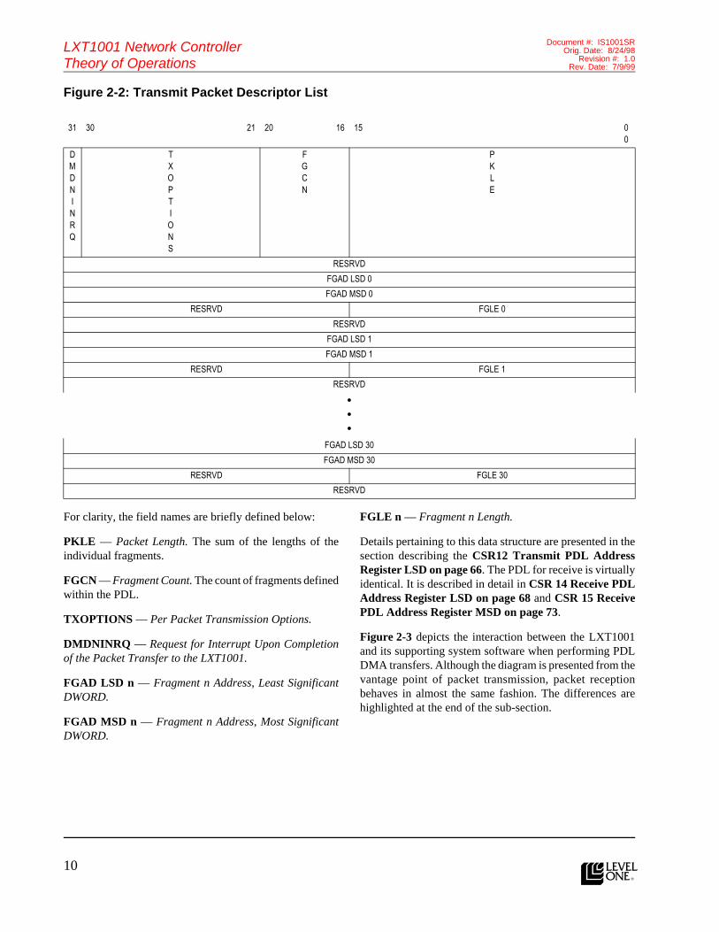
Packet Descriptor ListThe PDL technique is also commonly referred to asscatter-gather bus master. The PDL is a data structure thatis comprised of a header followed by a number of packetfragment descriptors. The header specifies the total lengthof the packet (the sum of the lengths of the fragments), the
number of fragments, and option flags indicating anyspecial processing requirements for the packet. Thefragment descriptors specify the physical memoryaddresses of the buffer fragments and their individuallengths. The data structure is arranged as follows (bit 0 isthe LSB):
FIFO
FIFO Control LogicTX Command Register
TX FIFO Write Register
TX FIFO Free Count Register
DeviceSoftware
DetermineAvailable Space
Write PacketData to Device
Instruct Device toTransmit Packet
{1}
{2}
{3}
10l
LXT1001 Network ControllerTheory of Operations
Document #: IS1001SROrig. Date: 8/24/98
Revision #: 1.0Rev. Date: 7/9/99
Features (cont.)Figure 2-2: Transmit Packet Descriptor List
For clarity, the field names are briefly defined below:
PKLE — Packet Length. The sum of the lengths of theindividual fragments.
FGCN — Fragment Count. The count of fragments definedwithin the PDL.
TXOPTIONS — Per Packet Transmission Options.
DMDNINRQ — Request for Interrupt Upon Completionof the Packet Transfer to the LXT1001.
FGAD LSD n — Fragment n Address, Least SignificantDWORD.
FGAD MSD n — Fragment n Address, Most SignificantDWORD.
FGLE n — Fragment n Length.
Details pertaining to this data structure are presented in thesection describing the CSR12 Transmit PDL AddressRegister LSD on page 66. The PDL for receive is virtuallyidentical. It is described in detail in CSR 14 Receive PDLAddress Register LSD on page 68 and CSR 15 ReceivePDL Address Register MSD on page 73.
Figure 2-3 depicts the interaction between the LXT1001and its supporting system software when performing PDLDMA transfers. Although the diagram is presented from thevantage point of packet transmission, packet receptionbehaves in almost the same fashion. The differences arehighlighted at the end of the sub-section.
31 30 21 20 16 15 00
DMDNINRQ
TXOPTIONS
FGCN
PKLE
RESRVD
FGAD LSD 0
FGAD MSD 0
RESRVD FGLE 0
RESRVD
FGAD LSD 1
FGAD MSD 1
RESRVD FGLE 1
RESRVD
•••
FGAD LSD 30
FGAD MSD 30
RESRVD FGLE 30
RESRVD
11
LXT1001 Network ControllerTheory of Operations
Document #: IS1001SROrig. Date: 8/24/98Revision #: 1.0Rev. Date: 7/9/99
l
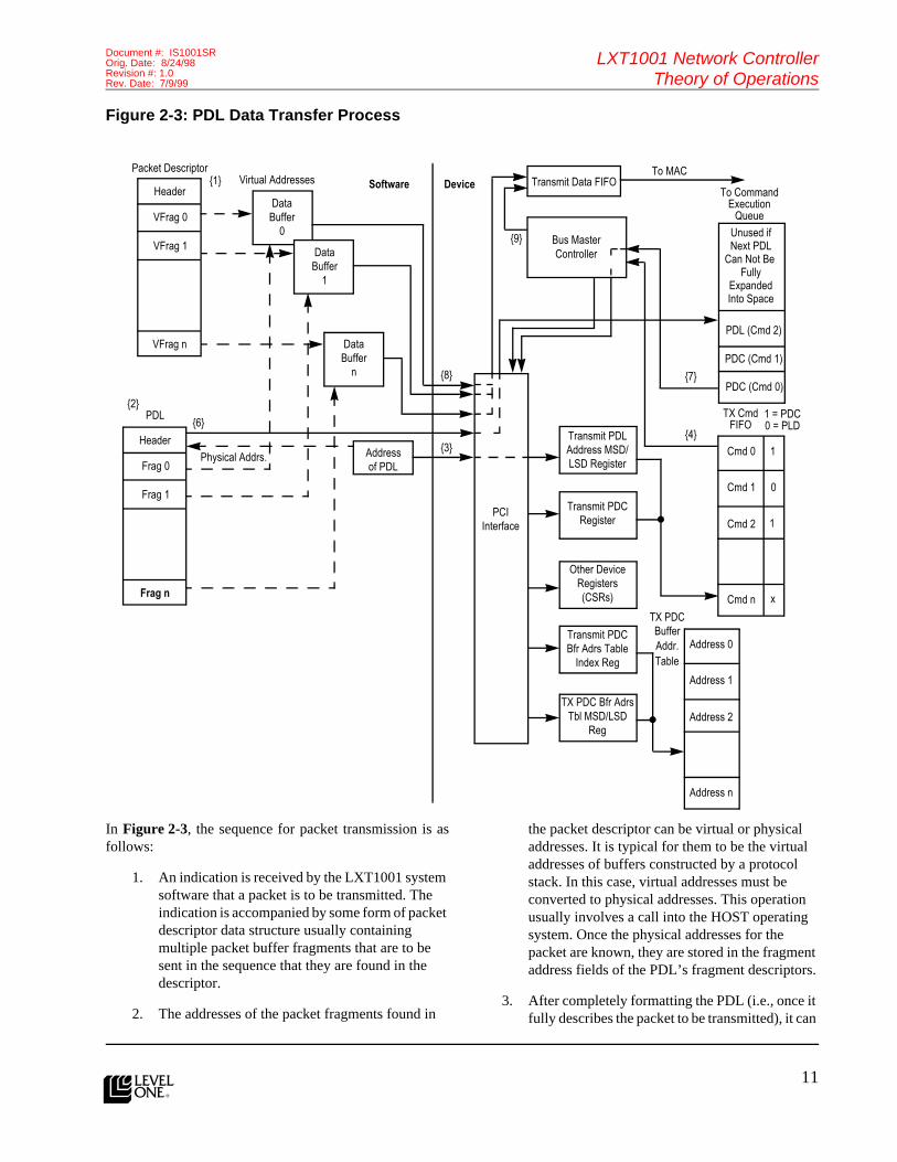
Figure 2-3: PDL Data Transfer Process
In Figure 2-3, the sequence for packet transmission is asfollows:
1. An indication is received by the LXT1001 system software that a packet is to be transmitted. The indication is accompanied by some form of packet descriptor data structure usually containing multiple packet buffer fragments that are to be sent in the sequence that they are found in the descriptor.
2. The addresses of the packet fragments found in
the packet descriptor can be virtual or physical addresses. It is typical for them to be the virtual addresses of buffers constructed by a protocol stack. In this case, virtual addresses must be converted to physical addresses. This operation usually involves a call into the HOST operating system. Once the physical addresses for the packet are known, they are stored in the fragment address fields of the PDL’s fragment descriptors.
3. After completely formatting the PDL (i.e., once it fully describes the packet to be transmitted), it can
Addressof PDL
DataBuffer
n
DataBuffer
1
DataBuffer
0
Header
VFrag 0
VFrag 1
•••
VFrag n
Header
Frag 0
Frag 1
•••
Frag n
Transmit PDLAddress MSD/LSD Register
Transmit PDCRegister
Other DeviceRegisters(CSRs)
Transmit PDCBfr Adrs Table
Index Reg
TX PDC Bfr AdrsTbl MSD/LSD
Reg
PCIInterface
PDL{2}
{6}
Physical Addrs.
{1}Packet Descriptor
•••
Virtual Addresses
{8}
{3}
Bus MasterController
{9}
Transmit Data FIFOTo MAC
To CommandExecution
Queue
Unused ifNext PDL
Can Not Be Fully
ExpandedInto Space
PDL (Cmd 2)
PDC (Cmd 1)
PDC (Cmd 0)
Address 0
Address 1
Address 2
Address n
•••
{7}
{4}
TX CmdFIFO
1 = PDC0 = PLD
Cmd 0
Cmd 1
Cmd 2
Cmd n
•••
1
0
1
x
•••
TX PDCBuffer
Table
Software Device
Addr.

12l
LXT1001 Network ControllerTheory of Operations
Document #: IS1001SROrig. Date: 8/24/98
Revision #: 1.0Rev. Date: 7/9/99
Features (cont.)be passed to the LXT1001 for processing. To do this, the starting physical address of the PDL in HOST memory is written to the Transmit PDL Address MSD Register/LSD Register. This action has the effect of placing the PDL’s address into the transmit command FIFO.
4. When one or more commands are present in the transmit command FIFO, the bus master LXT1001 (BMC) examines the FIFO and extracts the first available command. In our example, the queue is assumed to be empty prior to the transmit request, and thus the PDL is acted upon at the first available opportunity.
5. When the BMC looks at the command FIFO, it determines that the command is a PDL. Consequently, the BMC issues a request to the PCI block for the transfer of the PDL data structure from HOST memory to the Command Execution Queue (i.e., the header field and the fragment fields).
6. The PCI block responds to the request by effecting the necessary cycles on the bus to transfer the PDL into the Command Execution Queue.
7. Once the PDL is at the front of the Command Execution Queue, the BMC begins to “execute” it. It does so by interpreting the header, setting up its counters, pointers, etc., and then issuing commands to the PCI block to effect data transfers from HOST memory to the transmit data FIFO. For every fragment in the PDL, the BMC issues one data transfer command to the PCI block.
8. The PCI block transfers each packet fragment, one at a time to the transmit data FIFO.
9. Once the packet is completely transferred to the transmit data FIFO, the BMC signals the data FIFO that a complete packet has been transferred. The FIFO control logic then updates its pointers and signals the MAC that a packet is ready for transmission.
The process for receiving a frame differs from the processdescribed above in two respects:
1. The direction of the data flow is reversed.
2. The receive process is driven by the availability of incoming data and the availability of PDLs in the
receive command FIFO. In other words, if a packet arrives and there is no PDL or PDC in the receive command FIFO, then the packet will remain in the receive data FIFO until a PDL or PDC is placed into the receive command FIFO.
Packet Propulsion Method (Packet Descriptor Command)The PDC method for moving data is a specialization of thetraditional PDL technique. As previously noted, theprinciple notion of PDL is that a bus master device isinstructed to obtain a command block from HOST systemmemory. At a minimum, the command block contains a listof the physical addresses of the packet fragment buffers inHOST memory that are to be copied to the device, the countof packet buffer fragments, and the overall length of the datacontained in the fragments (the sum of the lengths of theindividual fragments).
The device parses the command block, extracting theaddress of each block of memory (fragment) to process, andeffects a transfer of the said fragment from HOST memoryto the device. The device repeats this process for eachfragment listed in the PDL until all of the data described bythe command is copied to the LXT1001 for transmission(the direction of the data flow is reversed for receive).
Contemplating the nature of the most important modernoperating systems, several key points become apparent:
• They support and practically require virtual memory.
• Devices that initiate data movement transactions across peripheral interconnect busses cannot use virtual memory addresses to affect the transfers.
• In terms of performance, the conversion of virtual addresses to physical addresses is an expensive one.
These points are significant primarily because of thesequence of events they impose on bus master devices.Again considering the traditional PDL technique, when datais passed to a bus master device, the corresponding devicedriver must first perform a virtual to physical addressconversion for each of the buffer fragments in the datatransfer operation. Moreover, a typical buffer passed to thedevice is broken up into several buffer fragments. That is,the data to be transferred to the device is segmented intoseveral pieces (typically three or four pieces). These factsresult in a situation whereby the cost of converting a virtualaddress to a physical one can be repeated several times foreach block of data that is to be transferred to the device.Given that the conversions are expensive, it is desirable toavoid them.

13
LXT1001 Network ControllerTheory of Operations
Document #: IS1001SROrig. Date: 8/24/98Revision #: 1.0Rev. Date: 7/9/99
l
One method for avoiding the virtual-to-physical addresstranslations is for the device driver to allocate blocks oflocked memory during device initialization. The addressconversion for these blocks can be performed once — at thepoint where the memory is allocated — and the physicaladdress can be stored away (e.g., in a queue). Each time thata request to transfer data to the device is received from theupper layers, the device driver could very quickly removethe next available memory block from the queue, copy thedata provided by the upper layer into the memory block,format a PDL, and then pass the PDL to the LXT1001. Thismethod has the following advantages:
• Virtual to physical address translation is avoided.
• The formatting of the PDL is simplified.
• The amount of data to be transferred to the LXT1001 in the PDL itself is reduced.
This method for processing DMAs is frequently referred toas “double copy” or “double buffer” DMA. Severalobservations can be made regarding this technique:
• The fragment count is always 1.
• The length value in the PDL header is the same as the length value of the first fragment.
• The physical address placed into the first fragment address field in the PDL is one of n possible physical addresses of pre-allocated locked buffers. Usually, n is 16, 32, 64, or some other suitably small integer (i.e., typically n <= 128, although it appears that future
drivers may begin using values for n that are more in the range of 128 ≤ n ≤ 1024).
Once it is clear that some of the fields in the PDL will alwayshave either the same value, or one value out of a small setof values, an expedited form of double buffering becomespossible. This expedited double buffer technique is calledPropulsion technology, or PDC.
The principal ideas behind Propulsion technology are asfollows:
• No command block (i.e., PDL) is formatted in HOST memory. Data transfer commands are communicated to the LXT1001 by passing a packet descriptor command. A PDC is a 32-bit value, subdivided into fields, that completely describes the data transfer operation. A PDC fits entirely within a device register and can be constructed entirely within a CPU register.
• Only one fragment (data buffer) per data transfer operation is communicated to the LXT1001 using a PDC (i.e., one buffer completely contains all of the data to be transferred to/from the LXT1001).
• The address of the data buffer is passed to the LXT1001 using a small (8-bit) ordinal value that indexes a table maintained on the LXT1001. The table has the complete set of physical addresses of buffers allocated by the DRIVER for data transfer purposes.
• The length of the buffer to be copied to/from LXT1001 is contained within the PDC command.
The actual format of a PDC command is as follows:
Upon closer inspection, one other optimization can berealized with the PDC technique. There is no restrictioninherent to the PDC technique that prevents multiplepackets from being copied by the HOST (or the LXT1001,depending on direction) into the pre-allocated data transferbuffers. In fact, if the data format used for the pre-allocatedbuffers parallels the data formats used internally by theLXT1001, then multiple packets can be easily formatted
into the PDC buffers and subsequently transferred to theLXT1001 with one I/O operation by the HOST (PDCcommand transfer to the LXT1001) and one burst transferof data by the LXT1001.
Thus, the Propulsion technique is efficient in its use of busbandwidth by minimizing the per-buffer overheadassociated with the transfer of data to/from the LXT1001.Note that the per-buffer overhead includes the number of
31
30
29
28
27
26
25
24
23
22
21
20
19
18
17
16
15
14
13
12
11
10
09
08
07
06
05
04
03
02
01
00
RESRVD
XFDNINRQ
BFID
BFLE

14l
LXT1001 Network ControllerTheory of Operations
Document #: IS1001SROrig. Date: 8/24/98
Revision #: 1.0Rev. Date: 7/9/99
Features (cont.)interactions between HOST software and the LXT1001(e.g., interrupts (especially on receive since multiplepackets can be delivered into a single PDC and only oneinterrupt is generated to signal their arrival)) commandblock exchanges, and PIO operations to the device.
Although the PDC technique is very efficient in its use ofbus bandwidth, this efficiency does not come without aprice. The single most significant drawback of the PDCmethod is that it requires that the processor move data fromapplication buffers into data transfer buffers — in otherwords, increased CPU utilization. At first glance, thisdouble copy would seem an insurmountable obstacle to theemergence of PDC as the preferred data transfer technique.However, when one considers that on average many tens,if not hundreds, of CPU clocks are expended in performingvirtual-to-physical address translations, and that oftentimes, many such translations are performed per buffertransferred to the LXT1001, it becomes evident that a largeamount of data can be moved by the CPU in the same
amount of time taken for an address translation. Certainlyfor small data transfers (and virtually half of all datatransfers are small), the technique is useful since many tens,if not hundreds, of bytes can be moved in the time it takesto make just one virtual-to-physical address translation.Moreover, as CPUs move to 64-bit and larger word sizes,the efficacy of this technique increases.
Another significant point is that the concern over CPUutilization is not paramount in all systems. Especially insystems where large amounts of data are moved about (e.g.,bus utilization is high) and the CPU has nothing else to do,then favoring bus utilization at the expense of CPUutilization can be a desirable trade-off to make. Thisargument can be extended to multiprocessor machineswhere CPU bandwidth outpaces bus bandwidth by a largemargin. Here, too, expending CPU utilization to gain busutilization may be a worthwhile trade-off.
Figure 2-4 depicts the process of data transfer using PDCs.

15
LXT1001 Network ControllerTheory of Operations
Document #: IS1001SROrig. Date: 8/24/98Revision #: 1.0Rev. Date: 7/9/99
l
Figure 2-4: PDC Data Transfer Process
The sequence for packet transmission when using PDCs isactually broken into two phases. The first phase happensonce during device/driver initialization. It consists of steps1, 2, and 3, as follows:
1. A pool of locked buffers is allocated from the system. Each buffer is made large enough to accommodate one or more full-size packets. If the individual buffers are made larger than the HOST system’s page size (for virtual memory systems), the buffers must be contiguous (i.e., in adjacent
pages with the lowest physical address residing in the lowest numbered page).
2. The Transmit PDC Buffer Address Table Index Register is pointed to the number 0 Buffer Address Table slot.
3. The addresses of the buffers in the pool are written to the table. Several important points can be mentioned here:
PDCBuffer
n
DataBuffer
n
DataBuffer
1
DataBuffer
0
Header
VFrag 0
VFrag 1
•••
VFrag n
Transmit PDLAddress MSD/LSD Register
Transmit PDCRegister
Other DeviceRegisters(CSRs)
Transmit PDCBfr Adrs Table
Index Reg
TX PDC Bfr AdrsTbl MSD/LSD
Reg
PCIInterface
PDC{1}
{4}Data Bfr Descriptor Virtual Addresses
{6}
Bus MasterCONTROLLER
{13}
Transmit Data FIFO To MACTo Command
ExecutionQueue
Unused ifNext PDL
Can Not Be Fully
ExpandedInto Space
PDL (Cmd 2)
PDC (Cmd 1)
PDC (Cmd 0)
Address 0
Address 1
Address 2
Address n
•••
{9}
{7}
TX CmdFIFO
1 = PDC0 = PLD
Cmd 0
Cmd 1
Cmd 2
Cmd n
•••
1
0
1
x
•••
TX PDCBuffer
Table
Software Device
BufferPool
PDCBuffer
1
PDCBuffer
0 Buf ID Len
PDC Command
{5}
{11}
{2}
{3}
{10}
{8}
{12}
Addr.

16l
LXT1001 Network ControllerTheory of Operations
Document #: IS1001SROrig. Date: 8/24/98
Revision #: 1.0Rev. Date: 7/9/99
Features (cont.)a. The Transmit PDC Buffer Address Table does
not need to be fully utilized. For example, if only two transmit PDC buffers are desired, then only two Transmit PDC Buffer Address Table entries need be used.
b. Addresses in the table do not need to be in adjacent slots.
c. Addresses in the table do not need to be in any particular order.
d. The Transmit PDC Buffer Address Table Index Register auto-increments with each write to the Transmit PDC Buffer Address LSD Register. This facilitates the writing of strings of buffer addresses to the device. However, the index register can be written prior to every write to the address MSD/LSD registers, thus allowing random write access to the table (both the address and index registers are write only).
The second phase is comprised of steps 4 through 13. Thesesteps happen each time one or more packets are transmittedusing a PDC buffer:
4. An indication is received by the LXT1001 system software that one or more packets are to be transmitted. The indication is accompanied by some form of packet descriptor data structure usually containing multiple packet buffer fragments (possibly describing multiple packets) that are to be sent in the sequence that they are found in the descriptor.
5. The addresses of the packet fragments found in the packet descriptor can be virtual or physical addresses. It is typical for them to be the virtual addresses of packet buffer fragments constructed by a protocol stack. The driver software responds by allocating (dequeing) a PDC buffer from the PDC buffer pool and block copying the packet(s) into successive locations within the PDC buffer. Note that in the case where multiple packets are transferred using a single PDC buffer, “fence posts” are inserted between the packets. Details pertaining to the fence posts are provided in the section describing the Transmit PDC LSD Register.
6. After copying all of the packet data to a PDC buffer, a PDC is formatted and passed to the LXT1001. To do this, the length of the PDC
buffer, the buffer ID corresponding to the buffer, and any processing options are formatted into a 32-bit CPU register. The contents of the CPU register are then written to the device’s Transmit PDC Register. This action has the effect of placing the PDC into the transmit command FIFO and setting a control bit in the FIFO identifying the command as a PDC.
7. When one or more commands are present in the transmit command FIFO, the bus master LXT1001 (BMC) is prompted to examine the FIFO and extract the first available command. In our example, the queue is assumed to be empty prior to the transmit request and thus the PDC is acted upon at the first available opportunity.
8. When the BMC looks at the command FIFO, it determines that the command is a PDC and moves it directly to the Command Execution Queue.
9. The BMC now takes the PDC command and begins to execute it. It does so by decoding the BFID and BFLE fields (see the Transmit PDC Register for a discussion of the PDC command format).
10. The BMC uses the BFID value in the PDC command to index the Transmit PDC Buffer Address Table and obtain the starting physical address of the buffer to be transferred to the LXT1001.
11. Once the PDC has been decoded and the starting physical address obtained, the BMC instructs the PCI block to initiate a buffer data transfer to the TX FIFO.
12. The PCI block transfers the buffer data to the TX FIFO at the next available opportunity.
13. Once the packet is completely transferred to the data FIFO, the BMC signals the data FIFO that a complete packet has been transferred. The FIFO control logic then updates its pointers and signals the MAC that a packet is ready for transmission.
OrganizationThe remainder of this section contains a pseudo-code driverfor device initialization, packet transmission, packetreception, and interrupt processing. The intent of thepseudo-code driver is to demonstrate the basic conceptsof programming the LXT1001 controller. It does not

17
LXT1001 Network ControllerTheory of Operations
Document #: IS1001SROrig. Date: 8/24/98Revision #: 1.0Rev. Date: 7/9/99
l
represent the only way or necessarily the optimal wayto operate the LXT1001 controller.
InitializationThis section contains a discussion of topics related to theinitialization of the LXT1001. Example pseudo-code is alsoprovided to demonstrate algorithms for initializing theLXT1001 for PIO, PDL, and PDC I/O methods.
ResetThe LXT1001 accepts two types of resets: hard reset andsoft reset. A hard reset occurs when the PCI RST signal isasserted. The LXT1001 takes the following actions whenperforming a hard reset:
• All internal state machines of the LXT1001 are reset to their initial state.
• All internal registers of the LXT1001 are reset to their default value.
• All CSRs are reset to their default value.
• All PCI configuration space registers are reset to their default value.
• If an EEPROM is present, the LXT1001 reads the EEPROM and reloads selected CSRs and PCI configuration registers with the values read from EEPROM. For a detailed list of the registers loaded from EEPROM, see EEPROM Map on page 123.
A soft reset occurs when HOST software sets the SWRE bitin Mode Register – 1. The LXT1001 takes the same actionsfor a soft reset as it does for a hard reset with one exception.During a soft reset, the LXT1001 does not reset the PCIconfiguration space registers. This is necessary to preservethe hardware resources assigned to the device by systemBIOS and/or the operating system.
If HOST software attempts to access the LXT1001 while ahard or soft reset is in progress, the LXT1001 generates aPCI retry until the reset has completed. The LXT1001indicates a PCI retry to the HOST/PCI bridge by assertingthe STOP and deasserting TRDY, while keeping DEVSELasserted during the first data phase of the access. Uponreceiving this indication, the HOST/PCI bridge terminatesthe transaction. After waiting at least two PCI bus cycles,the HOST/PCI bridge will retry the access. The HOST/PCIbridge will continue retrying until the access succeeds.From the perspective of HOST software, the I/O instructionthat generated the access blocks until the LXT1001’s resetcompletes. To avoid the PCI bus and processorinefficiencies associated with PCI retries, after initiating asoft reset, HOST software should wait 20 ms before it
attempts any I/O to the LXT1001. Delaying 20 ms allowsthe LXT1001 to fully reset without having to issue PCIretries.
Physical Layer Configuration and Status The LXT1001 supports three physical layer interfaces: MII,GMII, and PCS. Regardless of the type of PHY present,HOST software interacts with PHY using the G/MII PHYAccess Register. HOST software accesses PHY registersthrough this register. HOST software can assume the MIIbasic register set is present. The basic register set consistsof the Control Register (register 0) and the Status Register(register 1). GMII-compliant PHYs have an extended basicregister set that includes the Extended Status Register(register 15) in addition to the MII basic register set. If aPHY implements the Extended Status Register, it sets bit 8in its Status Register. See IEEE Standard 802.3z, clause 22,for a detailed description of the basic, extended basic, andextended register sets. HOST software can also accessvendor specific registers on the PHY using the G/MII PHYAccess Register.
To read the Status Register of the PHY at address 2, forexample, HOST software writes the following values to theG/MII PHY Access Register: GMRRIX = 1, GMCM = 0,GMPHAD = 2. HOST software then polls the registerwaiting for GMST = 0. When GMST = 0, the LXT1001 hascompleted the read operation and GMDA contains the valueread from PHY. Write operations occur in a similar manner,except that HOST software puts the value to be written tothe PHY register in the GMDA field when it initiates therequest to the G/MII PHY Access Register.
At initialization time, HOST software is responsible forquerying PHY to determine the type of PHY (MII or GMII),the current link speed, and the current duplex mode. Oncethis is determined, HOST software must set the appropriatevalues in the G/MII Mode Register. Setting the G/MII ModeRegister determines how the LXT1001 interacts with PHYwhen transmitting and receiving packets.
The LXT1001 has the capability to poll PHY’s StatusRegister and generate an interrupt when PHY’s StatusRegister changes. This capability provides an efficientmechanism to detect changes in the physical layer status.When the interrupt occurs, HOST software can query PHYto determine the exact change in PHY status. HOSTsoftware enables this capability by setting the GMSTPOENbit in Mode Register – 1 and the PHLASTMS bit in theInterrupt Mask Register.

18l
LXT1001 Network ControllerTheory of Operations
Document #: IS1001SROrig. Date: 8/24/98
Revision #: 1.0Rev. Date: 7/9/99
Features (cont.)PDC Buffer AllocationWhen using the PDC I/O method, HOST software mustallocate PDC buffers. HOST software allocates PDCbuffers such that they have the following attributes:
• A PDC buffer must be at least 64 bytes long.
• A PDC buffer is physically contiguous. A buffer may span one or more page boundaries as long as the pages are physically contiguous.
• A PDC buffer is locked. The operating system will not swap the buffer to disk or move it a new location in physical memory.
• If possible, the starting address of a receive PDC buffer is on a cache line boundary and the buffer length is evenly divisible by the cache line size. This allows the LXT1001 to use memory write and invalidate commands when transferring data into the buffer.
When HOST software allocates a PDC buffer, it places thephysical address of the PDC into either the Transmit PDCBuffer Address Table or the Receive PDC Buffer AddressTable. Each of these tables hold a maximum of 64 PDCs.HOST software does not have to use every entry in the table.
PDL Buffer AllocationWhen using the PDL I/O method, HOST software mustallocate PDL buffers. HOST software allocates PDL bufferssuch that they have the following memory attributes:
• A PDL buffer is physically contiguous. A buffer may span a page boundary as long as the pages are physically contiguous.
• A PDL buffer is locked. The operating system will not swap the buffer to disk or move it to a new location in physical memory.
• At a minimum, the starting address of a PDL buffer must begin on a QWORD boundary. If possible, the starting address of PDLs should begin on a cache line boundary and the PDL buffer length is a multiple of cache lines. This allows the LXT1001 to use memory write and invalidate commands when transferring data into the PDL buffer. The use of memory write and invalidate commands improves system performance by eliminating unnecessary cache line writes to memory.
The fragment buffers pointed to by a PDL have the samememory attributes as a PDL with the following exception:fragments can be allocated on any byte boundary. This isnecessary because fragments are typically allocated byupper layer software and are ephemeral in nature.Furthermore, the sum of the fragment lengths must be atleast 64 bytes.
System Initialization Event SequenceAt system initialization time, the following sequence ofevents occur.
1. The RST signal on the PCI bus is asserted, causing the LXT1001 to perform a hard reset.
2. HOST BIOS reads and writes the LXT1001’s PCI Configuration Space Registers to determine the LXT1001’s capabilities and resource requirements.
3. HOST BIOS assigns resources to the LXT1001 by writing to the LXT1001’s PCI Configuration Space Registers.
4. If an expansion ROM is attached to the LXT1001, HOST BIOS shadows (copies) the expansion ROM image into system RAM.
5. If the LXT1001 is the active boot device, HOST BIOS invokes the expansion ROM image to bring the LXT1001 to a fully operational state.
6. The operating system is loaded (either from a local disk or via the network connection provided by the LXT1001) and HOST BIOS gives control to the operating system.
7. The operating system loads and invokes the HOST device driver software for the LXT1001.
Initialization AlgorithmThe pseudo-code in Table 2-1 demonstrates a typicalalgorithm HOST device driver software uses to bring theLXT1001 to a fully operational state. The “@” in theright-hand column indicates lines where HOST softwareaccesses the LXT1001.

19
LXT1001 Network ControllerTheory of Operations
Document #: IS1001SROrig. Date: 8/24/98Revision #: 1.0Rev. Date: 7/9/99
l
Table 2-1: Initialization Pseudo-Code
(1) Function Initialize (TransmitPacketList)
(2) Locate the device using PCI services provided by BIOS or the operating system. @
(3) Query the CONTROLLER’s PCI Configuration Registers to determine the IO Base Address, Memory Base Address, and Interrupt level.
@
(4) Select the desired mode settings via Mode Register – 1 (CSR00) and Mode Register – 2 (CSR001)
@
(5) If (the user has configured a locally administered address)
(6) Program the locally administered address into the LAN Physical Address Registers (CSR42 and CSR43).
@
(7) Endif
(8) Query the PHY via G/MII PHY Access Register (CSR44) to determine the link status, duplex mode, and link speed.
@
(9) If (the current PHY mode is incompatible with the link speed, duplex mode, or auto-negotiation modes settings the user has requested)
(10) Reprogram the PHY to the user requested settings using CSR44. @
(11) If necessary, force the PHY to renegotiate with its link partner to reflect the new PHY settings.
@
(12) Endif
(13) Set the appropriate link speed and duplex mode values in the G/MII Mode Register (CSR45).
@
(14) Perform the BIST test using the BIST Register in the PCI Configuration space. @
(15) Call LoopbackTest(). See below. @
(16) If (the loopback test failed)
(17) Return indicating a fatal error occurred. @
(18) Endif
(19) If (a bus mastering method will be used to transmit packets)
(20) Read TXCMFECN from the Command Status Register (CSR51) and save the result in TxCommandsAvailable.
@
(21) Note: PDC and PDL modes are not mutually exclusive.
(22) If (the PDC I/O method will be used to transmit packets)
(23) Call InitializePDCTransmit() @
(24) Endif
(25) If (the PDL I/O method will be used to transmit packets)
(26) Call InitializePDLTransmit()
(27) Endif
(28) Else
(29) Read TXFIDWCN from the TX FIFO DWORDs Free Register (CSR21). @
(30) Set BytesFreeInTxFIFO = TXFIDWCN * the number of bytes in a DWORD.
(31) Endif

20l
LXT1001 Network ControllerTheory of Operations
Document #: IS1001SROrig. Date: 8/24/98
Revision #: 1.0Rev. Date: 7/9/99
Features (cont.)(32) If (PDC and/or PDL I/O method will be used for receiving)
(33) Read RXCMFECN from the Command Status Register (CSR51) and save the result in RxCommandsAvailable.
@
(34) If (the PDC I/O method will be used to receive packets)
(35) Call InitializePDCReceive(RxCommandsAvailable). @
(36) Endif
(37) If (the PDL I/O method will be used to receive packets)
(38) Call InitializePDLReceive(RxCommandsAvailable). @
(39) Endif
(40) Set the interrupt mask RXPDMS in the Interrupt Mask Register (CSR30). Thiswill cause an interrupt each time the CONTROLLER has filled a PDL or PDCwith a inbound packet.
@
(41) Else using PIO method
(42) Set the interrupt mask RXMS in the Interrupt Mask Register (CSR30). This will cause an interrupt when there is at least one packet in the RX FIFO.
@
(43) Endif
(44) Enable the transmitter and receiver by setting the TXEN and RXEN bits in Mode Register – 1 (CSR00).
@
(45) Install the interrupt service routine to handle interrupts generated by the CONTROLLER.
(46) Enable the CONTROLLER’s ability to generate an interrupt by setting the INENMS bit in the Interrupt Mask Register (CSR30).
@
(47) Return Success.
(48) Endfunction
(49)
(50) Function LoopbackTest()
(51) Enable MAC level loopback using the LPBKMD field in Mode Register – 2 (CSR01). @
(52) Enable the transmitter and receiver by setting the TXEN and RXEN bits in Mode Register – 1 (CSR00).
@
(53) Transmit a packet to self using PIO method. @
(54) Poll the RXPKAV bit in the Chip Status Register (CSR11) until it is set. @
(55) Receive the packet just transmitted using PIO receive. @
(56) If (errors occurred transmitting or receiving the loopback packet)
(57) Return indicating PIO loopback test failed.
(58) Endif
(59) Build and issue a PDL receive command to the CONTROLLER. @
(60) Build and transmit a packet to self using PDL method. @
(61) Wait for RXDMDNCN field in the Command Status Register (CSR51) to be non-zero.
@
(62) Examine the packet just received. @
(63) If (errors occurred transmitting or receiving the loopback packet)
Table 2-1: Initialization Pseudo-Code – continued

21
LXT1001 Network ControllerTheory of Operations
Document #: IS1001SROrig. Date: 8/24/98Revision #: 1.0Rev. Date: 7/9/99
l
(64) Return indicating PDL loopback test failed.
(65) Endif
(66) Build and issue a PDC receive command to the CONTROLLER. @
(67) Build and transmit a packet to self using PDC method. @
(68) Wait for RXDMDNCN field in the Command Status Register (CSR51) to be non-zero.
@
(69) Examine the packet just received. @
(70) If (errors occurred transmitting or receiving the loopback packet)
(71) Return indicating PDC loopback test failed.
(72) Endif
(73) Disable the transmitter and receiver by clearing the TXEN and RXEN bits in Mode Register – 1 (CSR00).
@
(74) Return success.
(75) Endfunction
(76)
(77) Function InitializePDCTransmit()
(78) Initialize TableIndex = 0.
(79) For (the number of transmit PDC buffers to be allocated — up to the maximum of 64)
(80) Allocate a transmit PDC buffer.
(81) Set the table index in the Transmit PDC Buffer Address Table Register (CSR02) to TableIndex.
(82) Write the physical address of the transmit PDC buffer to the Transmit PDC Buffer Address Registers (CSR05 and CSR04). Writing to CSR04 causes the TBIX to automatically increment.
@
(83) Add the PDC to the TransmitPDCAvailableList.
(84) Increment TableIndex.
(85) Endfor
(86) Endfunction
(87)
(88) Function InitializePDCReceive(ReceiveCommandsAvailable)
(89) Initialize TableIndex = 0.
(90) For (for the number of PDC buffers to be allocated — up to the maximum of 64)
(91) Allocate a PDC buffer from the operating system.
(92) Set the table index in the Receive PDC Buffer Address Table Register (CSR06) to TableIndex.
(93) Write the physical address of the receive PDC buffer to the Receive PDC Buffer Address Registers (CSR09 and CSR08). Writing to CSR08 causes the TBIX to automatically increment.
@
(94) Increment TableIndex.
(95) If (RxCommandsAvailable)
Table 2-1: Initialization Pseudo-Code – continued
22l
LXT1001 Network ControllerTheory of Operations
Document #: IS1001SROrig. Date: 8/24/98
Revision #: 1.0Rev. Date: 7/9/99
Features (cont.)
The initialization pseudo-code above and the pseudo-codefor packet transmission, packet reception, and interruptprocessing that follow constitute a pseudo driver of sorts.
The pseudo driver is based upon the following set ofassumptions and design points:
• The driver will transmit packets using the PIO I/O method or a mixture of PDL/PDC I/O methods. It does not mix the PIO I/O method with other I/O methods.
• The driver receives packets using the PIO mode, PDL, or PDC I/O methods. It does not mix I/O methods when receiving.
• The protocol stack provides a list of packets to transmit rather than one packet.
• The driver indicates received packets to the protocol stack one at a time.
The Initialize() function is the top level function. It isresponsible for bringing the device into an operational state.In a real driver, this function is called immediately after thedriver is loaded. The major tasks it performs are as follows:
• Locating the device
• Initializing the PHY
• Performing a MAC loopback test using the PIO I/O method
(96) Call PDCQueueReceiveCommand(PDC, ReceiveCommandsAvailable) See Table 2-7
(97) Else
(98) Put the PDC on ReceivePDCAvailableList.
(99) Endif
(100) Endfor
(101) Endfunction
(102)
(103) Function InitializePDLTransmit()
(104) For (the number of transmit PDL buffers to be allocated)
(105) Allocate a transmit PDL.
(106) Put the PDL on the TransmitPDLAvailableList.
(107) Endfor
(108) Endfunction
(109)
(110) Function InitializePDLReceive(RxCommandsAvailable)
(111) For (for the number of PDL buffers to be allocated)
(112) Allocate a PDL buffer from the operating system.
(113) If (RxCommandsAvailable)
(114) Allocate a ReceivePacketDescriptor from the operating system.
(115) Call PDLQueueReceiveCommand (PDL, ReceivePacketDescriptor, RxCommandsAvailable). See Table 2-6
@
(116) Else
(117) Put the PDL on ReceivePDLAvailableList.
(118) Endif
(119) Endfor
(120) Endfunction
Table 2-1: Initialization Pseudo-Code – continued

23
LXT1001 Network ControllerTheory of Operations
Document #: IS1001SROrig. Date: 8/24/98Revision #: 1.0Rev. Date: 7/9/99
l
• Allocating PDC buffers and initializing the PDC buffer address tables
• Allocating PDLs
• Hooking an interrupt and enabling the LXT1001’s ability to generate an interrupt for transmit and receive events
The variables used to model the LXT1001’s transmitter andreceiver states will be discussed in later sections.
Transmit Packet ProcessingThis section contains discussions on topics related totransmitting packets with the LXT1001. Examplepseudo-code is also provided to demonstrate algorithms fortransmitting a packet in PIO, PDL, and PDC modes.
Transmit Packet PaddingBy default, when transmitting a packet that is smaller thanthe minimum packet size, the LXT1001 adds padding bytesto the end of the packet. For Ethernet, the minimum packetsize is 60 bytes, excluding the CRC. The pad bytes addedby the LXT1001 are included in the CRC calculation of thepacket. The LXT1001’s ability to pad undersized packetscan be disabled by clearing the TXPPEN bit in ModeRegister – 1. When this feature is disabled, it is theresponsibility of HOST software to pad the packets prior togiving them to the LXT1001 for transmission. Failure to doso results in runt packets being transmitted on the network.
VLAN Tag Header InsertionThe LXT1001 provides the capability to insert VLAN tagheaders during the transmission of packets. See VLANSupport on page 40 for a detailed description of how to usethis function.
CRC GenerationBy default, the LXT1001 calculates and appends a 4-byteCRC to outbound packets. This capability can be disabledby clearing the TXCREN bit in Mode Register – 1. WhenTXCREN is cleared, it is the responsibility of HOSTsoftware to include a CRC in the packet data given to theLXT1001.
HOST software should ensure the TXCREN bit is setwhenever it has enabled other LXT1001 features that causethe LXT1001 to insert or modify packet data prior to thepacket’s transmission. In particular, the TXCREN bitshould be set when HOST software has enabled VLAN tagheader insertion, or transmit packet padding. Failure to setthe TXCREN in these circumstances results in a packet
containing an invalid CRC to be transmitted onto thenetwork.
Transmit Completion Status The LXT1001 implements a “lying send” transmit policy.This means a packet is considered to be successfullytransmitted as soon as it is copied into the LXT1001’s TXFIFO. When using the PIO I/O method, this occurs as soonas HOST software has moved the packet into the TX FIFO.When using the PDL and PDC I/O methods, this occurs assoon as the LXT1001 has transferred the packet data intothe TX FIFO. Ultimately, it is the responsibility of theprotocols above the driver to ensure that packets aresuccessfully transmitted to remote stations. If a packet islost during transmission by the LXT1001, the protocol isresponsible for recognizing that the packet is lost andeffecting a corrective action (e.g., retransmit).
Transmit StatisticsThe LXT1001 maintains the following packet transmissions t a t i s t i c s : a F r a m e s T r a n s m i t t e d O K ,aSingleCollisionFrames, aMultipleCollisionFrames,Errored Transmit Packet Count, TCP/IP Non Ipv4 PacketCount, and Late Collision Count. The counts do not wrap.See Table 4-1 for a detailed description of these statistics.
Simultaneous Use of PDL, PDC, and PIO I/O MethodsThe LXT1001 supports the use of PDL and PDC I/Omethods simultaneously. When transferring data, HOSTsoftware indicates the desired data transfer method by theCSR used to initiate the transfer. For packet transmissionusing the PDC I/O method, HOST software initiates theprocess by writing to the Transmit PDC Register. If theHOST wishes to transmit a packet using the PDL method,it writes to the Transmit PDL Address Register instead.
Although intermixing of PDC and PDL transmit commandsis directly supported by the LXT1001, intermixing of PIOwith either PDC or PDL transfer methods is not directlysupported. It is possible to intermix PIO with the other twotransfer methods, however, careful coordination must becarried out to prevent simultaneous accesses to the TX FIFOby the LXT1001’s System Interface Block and HOSTsoftware. More specifically, prior to initiating atransmission using the PIO method, HOST software mustguarantee that all PDL and/or PDC transmit commandsissued have been completed by the LXT1001. A PDL andPDC transmit command is considered completed when theLXT1001 has transferred the transmit packet data from

24l
LXT1001 Network ControllerTheory of Operations
Document #: IS1001SROrig. Date: 8/24/98
Revision #: 1.0Rev. Date: 7/9/99
Features (cont.)HOST memory into the LXT1001’s TX FIFO andincremented the TXDMDNCN count in the CommandStatus Register.
Programmed Input/Output Method of TransmissionPIO mode is often referred to as a slave mode. The two termsare used interchangeably in this document. In PIO mode,the HOST is responsible for effecting all packet datamovement to and from the LXT1001.
Transmitting a packet using the PIO method is a four-stepprocess:
1. Determining the TX FIFO has enough free space to accommodate the transmit header and packet
2. Writing the transmit header to the TX FIFO
3. Writing the packet data to the TX FIFO
4. Issuing the transmit command
The LXT1001 maintains a count of the number of freeDWORDs in the TX FIFO. The LXT1001 decrements thecount as data is written to the FIFO, and increments thecount as data is removed from the FIFO and transmitted.
HOST software ascertains this count by reading the TXFIFO DWORDs Free Register. If the TX FIFO does notcontain enough free space to accommodate the packet,HOST software must wait until enough free space exists.HOST software waits by polling, retrying periodically, orby requesting an interrupt be generated when the TX FIFOhits a low watermark. Refer to the TX FIFO Low WatermarkRegister description for more information on how togenerate a TX FIFO low watermark interrupt.
Once HOST software has determined the TX FIFO canaccommodate the packet, it constructs the transmit headerand writes it to the TX FIFO via the TX FIFO Write Register.Next, HOST software copies the data to the LXT1001’s TXFIFO by sequencing through the packet data and writing itto the TX FIFO Write Register. HOST software then setsthe SLMDTXCM bit in the Command Register to indicatethe entire packet is in the TX FIFO and is ready fortransmission. The LXT1001 transmits the packet data ontothe network in the order that it is written to the TX FIFOWrite Register.
The pseudo-code in Table 2-2 demonstrates how to transmita list of packets using the PIO data transfer method. Lineswith an “@” in the right-hand column indicate an access tothe LXT1001.
Table 2-2: PIO Transmit Pseudo-Code
(1) Function PIOTransmitPacketList(TransmitPacketList)
(2) Get the first packet from TransmitPacketList.
(3) While (there is a packet to be transmitted)
(4) PacketLength = the number of bytes in the packet.
(5) Set RetryCount = MAX_RETRIES + 1.
(6) While (BytesFreeInTxFIFO < PacketLength + number of bytes in the transmit header)
(7) If (RetryCount = 0)
(8) Set the transmit status code for the current and all remaining packets in TransmitPacketList to indicate they did not transmit.
(9) Return out of TX FIFO resources.
(10) Endif
(11) Read TXFIDWCN from the TX FIFO DWORDs Free Register (CSR21). @
(12) Set BytesFreeInTxFIFO = TXFIDWCN * the number of bytes in a DWORD.
(13) Decrement RetryCount.
(14) Endwhile
(15) Determine the per packet processing options.
25
LXT1001 Network ControllerTheory of Operations
Document #: IS1001SROrig. Date: 8/24/98Revision #: 1.0Rev. Date: 7/9/99
l
The PIO transmit pseudo-code models the LXT1001’stransmitter using the variable BytesFreeInTxFIFO. Thisvariable represents the minimum number of unused bytesin the TX FIFO at any given point in time. The variable isused to determine if there is enough space in the TX FIFO
to accommodate a packet and its transmit header. Initially,BytesFreeInTxFIFO is set to the size of the TX FIFO. Eacht i m e a p a c k e t i s c o p i e d i n t o t h e T X F I F O ,BytesFreeInTxFIFO decrements by the number of bytes in
(16) Construct the FIFO Transmit Header using the PacketLength and per packet processing options.
(17) Write the FIFO Transmit Header to the TX FIFO Write Register (CSR22). @
(18) For (each fragment in the packet)
(19) If (the fragment starting address is odd)
(20) Write the first BYTE of the fragment to the TX FIFO Write Register (CSR22).
@
(21) Endif
(22) If (the fragment starting address is not evenly divisible by the size of a DWORD)
(23) Write the next WORD of the fragment to the Transmit FIFO Write Register(CSR22).
@
(24) Endif
(25) While (at least a DWORD remains in the fragment)
(26) Write the next DWORD of the fragment to the Transmit FIFO Write Register (CSR22).
@
(27) Endwhile
(28) If (at least a WORD is remains in the fragment)
(29) Write the next WORD of the fragment to the Transmit FIFO Write Register (CSR22).
@
(30) Decrement the remainder by the size of a WORD.
(31) Endif
(32) If (a BYTE remains in the fragment)
(33) Write the next BYTE of the fragment to the TX FIFO Write Register (CSR22).
@
(34) Endif
(35) Endfor
(36) Decrement BytesFreeInTxFIFO by (the number of bytes in the packet rounded up to the next multiple of 8) + the size of the transmit header.
(37) Start the PIO transmit by setting the SLMDTXCM in the Command Register (CSR29).
@
(38) Set the packet’s transmit status code to success.
(39) Get the next packet in the TransmitPacketList.
(40) Endwhile
(41) Return Success.
(42) Endfunction
Table 2-2: PIO Transmit Pseudo-Code – continued

26l
LXT1001 Network ControllerTheory of Operations
Document #: IS1001SROrig. Date: 8/24/98
Revision #: 1.0Rev. Date: 7/9/99
Features (cont.)the packet plus the size of the transmit header rounded upto the next QWORD boundary.
Packet Descriptor List Method of TransmissionThe pseudo-code in Table 2-3 demonstrates how to transmita list of packets using the PDL data transfer method. Lineswith an “@” in the right-hand column indicate an access tothe LXT1001.
Table 2-3: PDL Transmit Pseudo-Code
(1) Function PDLTransmitPacketList(TransmitPacketList)
(2) Get the first packet from TransmitPacketList.
(3) While (there is a packet to be transmitted)
(4) If (TransmitCommandsAvailable = 0)
(5) Read TXCMFECN from the Command Status Register (CSR51). @
(6) If (TXCMFECN = 0)
(7) Set the transmit status code for the current and all remaining packets in TransmitPacketList to indicate they did not transmit.
(8) Return indicating no more transmit commands are available.
(9) Else
(10) TransmitCommandsAvailable = the value read from TXCMFECN.
(11) Endif
(12) Endif
(13) If (a PDL buffer is available)
(14) Get a PDL from the TransmitPDLAvailableList.
(15) TotalLength = 0.
(16) PDLFragmentIndex = 0.
(17) For (each fragment in the packet)
(18) If (the fragment is not in locked memory)
(19) Call the operating system to lock the memory.
(20) Endif
(21) If (the fragment address is a virtual address)
(22) Call operating system to convert the virtual address to a list of physical addresses.
(23) Endif
(24) For (each of the virtual fragment’s physical addresses)
(25) Set PDL.FGAD[PDLFragmentIndex] to the physical fragmentaddress.
(26) Set PDL.FGLE[PDLFragmentIndex] to the number of bytes in the physical fragment.
(27) TotalLength = TotalLength + the number of bytes in the physical fragment.
(28) Move to the next physical fragment in the physical address list.

27
LXT1001 Network ControllerTheory of Operations
Document #: IS1001SROrig. Date: 8/24/98Revision #: 1.0Rev. Date: 7/9/99
l
The PDL transmit pseudo-code models the LXT1001’stransmitter state using the following variables:
• TransmitCommandsAvailable — This variable is the minimum number of additional transmit commands the LXT1001 can take at any given point in time. Each time a transmit PDL or PDC command is given to the LXT1001, this count decrements. When it reaches 0, the count is refreshed by reading the TXCMFECN field in the Command Status Register.
• TransmitPDLAvailableList — This is a list of PDLs available for transmitting packets. This pool of transmit
PDLs is allocated at initialization time. Each time a packet is transmitted using the PDL I/O method, a PDL is removed from this list. PDLs are returned to this list after a PDL transmit command completes.
• TransmitCommandsInProgressQueue — This is a FIFO queue of PDL and PDC commands issued to the LXT1001. This queue preserves the ordering in which the commands were issued to the LXT1001. When a transmit PDL or PDC command is given to the LXT1001, the PDL or PDC is enqueued on this queue.
(29) Increment PDLFragmentIndex.
(30) Endfor
(31) Endfor
(32) Set PDL.PKLE field to the TotalLength calculated.
(33) Set PDL.FGCN field to PDLFragmentIndex.
(34) Set the desired per packet processing options in the PDL header.
(35) Queue the PDL onto the TransmitCommandsInProgressQueue.
(36) Write the MSD of the PDL’s physical address to Transmit PDL Address MSD Register (CSR13).
@
(37) Write the LSD of the PDL’s physical address to Transmit PDL Address LSD Register (CSR12).
@
(38) Set the transmit status code status for the packet to indicate the transmit is in progress.
(39) Decrement TransmitCommandsAvailable.
(40) Else
(41) Set the transmit status code for the current and all remaining packets in TransmitPacketList to indicate they did not ransmit.
(42) Return indicating no more PDLs are available.
(43) Endif
(44) Get the next packet in the TransmitPacketList.
(45) Endwhile
(46) Return Success
(47) Endfunction
(48)
(49) Function PDLTransmitDMADoneEvent(PDL)
(50) Call the protocol stack and indicate the packet associated with this PDL was transmitted successfully.
(51) Queue the PDL on the TransmitPDLAvailableList.
(52) Endfunction
Table 2-3: PDL Transmit Pseudo-Code – continued
28l
LXT1001 Network ControllerTheory of Operations
Document #: IS1001SROrig. Date: 8/24/98
Revision #: 1.0Rev. Date: 7/9/99
Features (cont.)Items are taken off this queue when a TXDMDNIN interrupt occurs.
The PDLTransmitPacketList() function transmits a list ofpackets it is given as input. For each packet in the list, itperforms the following major tasks:
• Determines if the LXT1001 can accept any more transmit commands
• Prepares the fragments that constitute a packet to be transmitted for the LXT1001 — Preparing the fragments involves:
• Locking the fragments memory
• Acquiring the physical addresses of the fragments
• Constructs a PDL using the physical addresses and lengths of the fragments
• Writes the physical address of the PDL to the LXT1001’s Transmit PDL Address Registers (CSR13 and CSR12)
PDLTransmitDMADoneEvent() is called by the interrupthandler each time the LXT1001 has completed processingfor a transmit PDL. When called, it notifies the protocolstack that the packet has been transmitted successfully andreturns the PDL associated with the packet back to the listof available transmit PDLs.
Packet Propulsion Mode Method of TransmissionThe pseudo-code in Table 2-4 demonstrates how to transmita list of packets using the PDC data transfer method. Lineswith an “@” in the right-hand column indicate an access tothe LXT1001.
Table 2-4: PDC Transmit Pseudo-Code
(1) Function PDCTransmitPacketList(TransmitPacketList)
(2) Set Offset = size of PDC Buffer to cause a PDC to be obtained during the first iteration of the loop.
(3) Set PDC = NULL to indicate there is not a PDC awaiting ready to be given to the CONTROLLER.
(4) Get the first packet from TransmitPacketList.
(5) While (there is a packet to be transmitted)
(6) If (TransmitCommandsAvailable = 0)
(7) Read TXCMFECN from the Command Status Register (CSR51). @
(8) If (TXCMFECN = 0)
(9) Set the transmit status code for the current and all remaining packets in TransmitPacketList the list to indicate they did not transmit.
(10) Return indicating no more transmit commands are available.
(11) Else
(12) TransmitCommandsAvailable = the value read from TXCMFECN.
(13) Endif
(14) Endif
(15) PacketLength = the number of bytes in the packet.
(16) If (the size of the PDC buffer – Offset < PacketLength + the size of the PDC transmit header)
(17) If (PDC is not NULL)
(18) Call StartPDCTransmit(Offset, PDC’s Buffer ID).
(19) Endif
(20) If (a PDC structure is available)
(21) Get a PDC from the TransmitPDCAvailableList.

29
LXT1001 Network ControllerTheory of Operations
Document #: IS1001SROrig. Date: 8/24/98Revision #: 1.0Rev. Date: 7/9/99
l
(22) HeaderOffset = 0.
(23) Else
(24) Set the transmit status code for the current and all remaining packets in TransmitPacketList the list to indicate they did not transmit.
(25) Return indicating no more PDCs are available.
(26) Endif
(27) Else
(28) HeaderOffset = Offset.
(29) Endif
(30) Offset = HeaderOffset + the size of the PDC transmit header.
(31) For (each fragment in the packet)
(32) Copy fragment data to PDC[Offset].
(33) Offset = Offset + the number of bytes in the fragment.
(34) Endfor
(35) Set the desired packet processing options in the PDC[HeaderOffset].
(36) Set PDC[HeaderOffset].LEN = PacketLength.
(37) Offset = HeaderOffset + size of the PDC transmit header + PacketLength.
(38) Round up the Offset to the next QWORD boundary.
(39) Set the packet’s transmit status code to success.
(40) Get the next packet in the TransmitPacketList.
(41) Endwhile
(42) If (PDC is not NULL)
(43) Call StartPDCTransmit(Offset, PDC’s Buffer ID).
(44) Endif
(45) Return Success.
(46) Endfunction
(47)
(48) Function StartPDCTransmit(ActualPDCLength, PDCBufferID)
(49) If (interrupt wanted after data transfer from PDC has completed)
(50) Set the TransferDoneInterruptFlag.
(51) Endif
(52) Construct the PDC Transmit Command with the ActualPDCLength, the PDCBufferID, and the TransferDoneInterrupt flag.
(53) Queue the PDC onto the TransmitCommandsInProgressQueue.
(54) Write the PDC Transmit Command to the Transmit PDC Register (CSR16). @
(55) Decrement TransmitCommandsAvailable.
(56) Endfunction
(57)
Table 2-4: PDC Transmit Pseudo-Code – continued

30l
LXT1001 Network ControllerTheory of Operations
Document #: IS1001SROrig. Date: 8/24/98
Revision #: 1.0Rev. Date: 7/9/99
Features (cont.)
The PDC transmit pseudo-code models the LXT1001’stransmitter state using the following variables:
• TransmitCommandsAvailable — This variable is the minimum number of additional transmit commands the LXT1001 can take at any given point in time. Each time a transmit PDL or PDC command is given to the LXT1001, this count decrements. When it reaches 0, the count is refreshed by reading the TXCMFECN field in the Command Status Register.
• TransmitPDCAvailableList — This is a list of PDCs available for transmitting packets. This pool of transmit PDCs is allocated at initialization time. Each time a packet is transmitted using the PDC I/O method, a PDC is removed from this list. PDCs are returned to this list after a transmit PDC command has completed.
• TransmitCommandsInProgressQueue — This is a FIFO queue of PDL and PDC commands issued to the LXT1001. This queue preserves the ordering in which the commands were issued to the LXT1001. When a transmit PDL or PDC command is given to the LXT1001, it is enqueued on this queue. Items are taken off this queue when a TXDMDNIN interrupt occurs.
PDCTransmitPacketList() transmits a list of packets it isgiven as input. It performs the following major tasks:
• Determines if the LXT1001 can accept more transmit commands
• Gets a PDC from the pool of available PDCs
• Copies as many packets as it can into the PDC
• When the PDC can not hold the next packet in the list, the PDC is added to the TransmitCommandsInProgressQueue and is given to the LXT1001 by writing the PDC’s index in the Transmit PDC Address Table to the Transmit PDC Register (CSR16).
The above steps are repeated until all packets aretransmitted, no more PDCs are available, or the LXT1001can not accept any more commands.
Since PDCTransmitPacketList() copies the packet data intoa transmit PDC buffer, it reports the packet as having beentransmitted successfully without having to wait for theTXMDNIN to occur.
PDCTransmitDMADoneEvent() is called by the interrupthandler each time the LXT1001 has completed processingfor a transmit PDC. When called, it returns the PDC to thelist of available transmit PDCs.
(58) Function PDCTransmitDMADoneEvent(PDC)
(59) Queue the PDC on the TransmitPDCAvailableList.
(60) Endfunction
Table 2-4: PDC Transmit Pseudo-Code – continued

31
LXT1001 Network ControllerTheory of Operations
Document #: IS1001SROrig. Date: 8/24/98Revision #: 1.0Rev. Date: 7/9/99
l
Receive Packet ProcessingThis section contains discussions on topics related toreceiving packets with the LXT1001. Example pseudo-codeis also provided to demonstrate algorithms for transmittinga packet in PIO, PDL, and PDC modes.
Packet Reception FiltersThe LXT1001 provides packet reception filters that can beapplied to received packets to determine whether or not aninbound packet is transferred to HOST memory andindicated to HOST software. The packet reception filtersoperate concurrently with respect to one another and thereception of the packet. Conceptually, however, the filtersoperate in a hierarchical manner. A packet must pass eachactive filter in the hierarchy before it is transferred to HOSTmemory and indicated to HOST software.
The first filter in the hierarchy is the destination addressfilter. The destination address filter accepts/rejects framesbased on the 6-byte destination address in a receivedpacket’s MAC header. The acceptance of unicast,broadcast, and multicast packets can be enabled anddisabled independently via the UCEN, BCEN, and MCENbits in Mode Register – 1. When UCEN is set, the packetwill pass the destination address filter if the destinationaddress matches the address in the LAN Physical AddressRegisters. When the BCEN bit is set, packets containing theall stations broadcast address will pass the destinationaddress filter. When the MCEN bit is set, the LXT1001performs a hash operation on the destination address fieldof multicast packets. The result of the hash operation is anindex into a 64-bit hash table. If the hash table bit at theindex is set, the packet will pass the destination addressfilter, otherwise the packet is rejected. The LXT1001 canbe configured to operate in promiscuous mode by settingthe POEN bit in Mode Register – 1. In promiscuous mode,all packets pass the destination address filter. See thedefinitions for Mode Register – 1 and the Multicast HashTable LSD/MSD Register for more details on configuringthe destination filter.
The second filter in the hierarchy is the VLAN tag filter.The VLAN tag filter only affects received packetscontaining a VLAN tag header. When configured by HOSTsoftware, the VLAN tag filter passes packets containing aVLAN tag header that matches the protocol ID value0x8100 and a tag control information (TCI) field in theVLAN Tag TCI Table. See “VLAN Support” on page 42for a detailed description of the LXT1001’s VLAN support.
The third filter in the hierarchy is the errored packet filter.By default, the errored packet filter is enabled and rejectsreceived packets for which the LXT1001 detects an error.The LXT1001 detects CRC, alignment, runt, length, andlarge packet errors. HOST software can change thisbehavior by setting the PAERPKEN bit in Mode Register –1. When PAERPKEN is set, the LXT1001 allows HOSTsoftware to receive packets containing errors. In this case,the LXT1001 will set the appropriate error status bits in thepacket’s receive header. Regardless of the state of thePAERPKEN bit, the LXT1001 always forwards receivedpackets that result in an overflow error (EROV).
The final filter is the TCP/IP checksum filter. When enabledby HOST software, the LXT1001 rejects received packetscontaining TCP/IP checksum errors. See “TCP/IPChecksum Support” on page 43 for a detailed descriptionof the LXT1001’s TCP/IP checksum support.
Packet Receive StatusCRC, runt packet, alignment, and long packet errors aredetected by the LXT1001 and are signaled to HOSTsoftware by way of specific bits in the PIO/PDL/PDCReceive header. The packet receive header also containsadditional information bits pertaining to the type ofdestination address the packet contained, whether or not thepacket contained valid TCP/IP checksums, and whether ornot the packet contained a VLAN tag. For details on the PIOreceive header, see Figure 4-8. For details on the PDLreceive header, see Figures 4-2 and 4-3. For details on thePDC receive header, see Figure 4-5.
Receive StatisticsThe LXT1001 maintains the following packet receptions t a t i s t i c s : a F r a m e s R e c e i v e d O K ,aFrameCheckSequenceErrors, aAlignmentErrors, DroppedPacket Count, Errored Receive Packet Count, Runt PacketCount, Large Packet Count, VLAN Accepted Packet Count,TCP/IP Checksum Error Count, and VLAN DiscardedPacket Count. Refer to Table 4-1 for a detailed descriptionof these statistics.
Large Packet ReceptionBy default, the LXT1001 regards a packet that exceeds themaximum packet size as an error. Such frames will not beseen by HOST software unless the PAERPKEN bit is set inMode Register – 1. If the PAERPKEN bit is set, theLXT1001 passes the packet to HOST software and sets theERROR and LGPK status bits in the packet’s receive headerto indicate the packet contains an error.

32l
LXT1001 Network ControllerTheory of Operations
Document #: IS1001SROrig. Date: 8/24/98
Revision #: 1.0Rev. Date: 7/9/99
Features (cont.)By setting the LGPKEN bit in Mode Register – 1, HOSTsoftware can modify the LXT1001’s large packetprocessing. When LGPKEN is set, the LXT1001 does notregard a packet that exceeds the maximum packet size as anerror. In this case, the LXT1001 passes large packets toHOST software, regardless of the state of the PAERPKENbit, and sets the LGPK bit in the packet’s receive header.
Simultaneous Use of PDL, PDC, and PIO I/O MethodsThe LXT1001 supports the use of PDL and PDC I/Omethods simultaneously. When transferring data, HOSTsoftware indicates the desired data transfer method by theCSR used to initiate the transfer. For packet reception usingthe PDC I/O method, HOST software initiates the processby writing to the Receive PDC Register. If the HOST wishesto receive a packet using the PDL method, it writes to theReceive PDL Address Register instead.
Although intermixing of PDC and PDL receive commandsis directly supported by the LXT1001, intermixing of PIO
with either PDC or PDL transfer methods is not directlysupported. It is possible to intermix PIO with the other twotransfer methods, however, careful coordination must becarried out to prevent inadvertent simultaneous accesses bythe LXT1001’s system interface block and HOST software.More specifically, prior to initiating a receive using the PIOmethod, HOST software must guarantee that all PDL and/orPDC receive commands have been completely processedby the LXT1001. A PDL and PDC receive command isconsidered completely processed when the LXT1001 hastransferred the receive packet data from the LXT1001’s RXFIFO into HOST memory and incremented theRXDMDNCN count in the Command Status Register.
Programmed Input/Output (PIO) Method of ReceptionThe pseudo-code in Table 2-5 demonstrates how to receivea packet using the PIO data transfer method. Lines with an“@” in the right-hand column indicate an access to theLXT1001.
Table 2-5: PIO Receive Pseudo-Code
(1) Function PIOProcessReceiveEvent()
(2) Read the RX FIFO Packet Count Register (CSR28) to see how many packets have been received and save the result in ReceivePacketsAvailable.
@
(3) While (ReceivePacketsAvailable > 0)
(4) While (ReceivePacketsAvailable > 0)
(5) Read the RX FIFO Read Register (CSR24) to get the first DWORD of the Receive Header.
@
(6) PacketLength = LEN field in the first DWORD of the Receive Header.
(7) Read the RX FIFO Read Register (CSR24) to get the second DWORD of the Receive Header.
@
(8) Set NumDWORDS = (PacketLength + size of a DWORD – 1)/ size of a DWORD.
(9) Acquire a receive buffer large enough to hold NumDWORDS of receive data.
(10) If (no receive buffers are available)
(11) Set the RXFISKPK in the Command Register (CSR29) to skip the partially read packet.
@
(12) Return (indicating out of receive buffer resources).
(13) Endif
(14) Set the ReceivePacketBuffer to the address of the receive buffer just allocated.
(15) For (NumDWORDS)
(16) Read a DWORD from the RX FIFO Read Register (CSR24) into the ReceivePacketBuffer.
@

33
LXT1001 Network ControllerTheory of Operations
Document #: IS1001SROrig. Date: 8/24/98Revision #: 1.0Rev. Date: 7/9/99
l
The PIO receive pseudo-code is very simple. The RXMSbit in the Interrupt Mask Register is set at initialization time.Setting this bit causes the LXT1001 to generate an interrupteach time a complete packet has been put in the RX FIFO.Upon determining that an RXIN interrupt event haso c c u r r e d , t h e i n t e r r u p t h a n d l e r d i s p a t c h e sPIOProcessReceiveEvent(). PIOProcessReceiveEvent()uses the RX FIFO Read Register (CSR24) to read the
packet’s receive header from the FIFO. The receive headercontains the length of the packet. The function thenperforms an even number of DWORD reads of CSR24 andputs the data read into HOST memory. The functionproceeds in this manner until the RX FIFO Packet CountRegister (CSR28) indicates no more packets are in the RXFIFO.
(17) Advance the ReceivePacketBuffer pointer by one DWORD.
(18) Endfor
(19) If (NumDWORDS is an odd number)
(20) Read a DWORD from the RX FIFO Read Register (CSR24) and discard the value read. This is necessary to keep the FIFO QWORD aligned.
@
(21) Endif
(22) Call the protocol stack and give it the ReceivePacketBuffer.
(23) If (the protocol stack has copied the data)
(24) Free the ReceivePacketBuffer.
(25) Endif
(26) Decrement the ReceivePacketsAvailable count.
(27) Endwhile
(28) Read the RX FIFO Packet Count Register (CSR28) to see how many packets have been received and save the result in ReceivePacketsAvailable.
@
(29) Endwhile
(30) Return Success.
(31) Endfunction
Table 2-5: PIO Receive Pseudo-Code – continued

34l
LXT1001 Network ControllerTheory of Operations
Document #: IS1001SROrig. Date: 8/24/98
Revision #: 1.0Rev. Date: 7/9/99
Features (cont.)Packet Descriptor List Method of ReceptionThe pseudo-code in Table 2-6 demonstrates how to receivea packet using the PDL data transfer method. Lines with an
“@” in the right-hand column indicate an access to theLXT1001.
Table 2-6: PDL Receive Pseudo-Code
(1) Function PDLQueueReceiveCommand(PDL, ReceivePacketDescriptor)
(2) If (ReceiveCommandsAvailable = 0)
(3) Read RXCMFECN from the Command Status Register (CSR51). @
(4) If (RXCMFECN = 0)
(5) Return indicating no more receive commands are available.
(6) Else
(7) ReceiveCommandsAvailable = the value read from RXCMFECN.
(8) Endif
(9) Endif
(10) TotalLength = 0.
(11) PDLFragmentIndex = 0
(12) For (each fragment in the ReceivePacketDescriptor)
(13) If (the fragment is not in locked memory)
(14) Call the operating system to lock the memory.
(15) Endif
(16) If (the fragment address is a virtual address)
(17) Call the operating system to convert the virtual address to a list of physical addresses.
(18) Endif
(19) For (each of the virtual fragment’s physical addresses)
(20) Set PDL.FGAD[PDLFragmentIndex] to the physical fragment address.
(21) Set PDL.FGLE[PDLFragmentIndex] to the number of bytes in the physical fragment.
(22) TotalLength = TotalLength + the number of bytes in the physical fragment.
(23) Move to the next physical fragment in the physical address list.
(24) Increment PDLFragmentIndex.
(25) Endfor
(26) Endfor
(27) Set PDL.PKLE field to the TotalLength calculated.
(28) Set PDL.FGCN field to the number of fragments in the ReceivePacketDescriptor.
(29) Set the desired per packet processing options in the PDL header.
(30) Enqueue the PDL onto the ReceiveCommandsInProgressQueue.
(31) Write the MSD of the PDL’s physical address to Receive PDL Address MSD Register (CSR15)
@

35
LXT1001 Network ControllerTheory of Operations
Document #: IS1001SROrig. Date: 8/24/98Revision #: 1.0Rev. Date: 7/9/99
l
The PDL receive pseudo-code uses the following variablesto model the state of the LXT1001’s receiver:
• ReceiveCommandsAvailable — This variable is the minimum number of additional receive commands the LXT1001 can take at any given point in time. Each time a receive PDL command is given to the LXT1001, this count decrements. When it reaches 0, the count is refreshed by reading the RXCMFECN field in the Command Status Register.
• ReceiveCommandsDone — This variable is effectively the RXDMDNCN from the Command Status Register (CSR51). The RXDMDNCN is also aliased into the Event Status Register (CSR32). Each time the Event Status Register is read, the RXDMDNCN is added to ReceiveCommandsDone. This determines how many
items are taken off the ReceiveCommandsInProgressQueue following an interrupt.
• ReceiveCommandsInProgressQueue — This is a FIFO queue of PDL receive commands issued to the LXT1001. This queue preserves the ordering in which the commands were issued to the LXT1001. When a PDL receive command is given to the LXT1001, the PDL is enqueued on this queue. PDLs are taken off this queue when an RXDMDNIN interrupt occurs.
• ReceivePDLAvailableList — This is a list of PDLs that are available for receiving packets. This pool of receive PDLs is allocated at initialization time. Each time a packet is received using the PDL I/O method, a PDL is removed from this list. PDLs are returned to this list
(32) Write the LSD of the PDL’s physical address to Receive PDL Address LSD Register (CSR14)
@
(33) Decrement the ReceiveCommandsAvailable count.
(34) Return Success.
(35) Endfunction
(36)
(37) Function PDLProcessReceiveEvent(ReceiveCommandsDone)
(38) While (ReceiveCommandsDone > 0)
(39) Dequeue the PDL from the ReceiveCommandsInProgressQueue.
(40) Get the ReceivePacketDescriptor corresponding to this PDL.
(41) Update the length fields in the ReceivePacketDescriptor to reflect the lengthsreturned in the PDL.
(42) Examine the receive status codes in the PDL receive header and update the ReceivePacketDescriptor as necessary.
(43) Call the protocol stack to give it the ReceivePacketDescriptor.
(44) Call the operating system to get another ReceivePacketDescriptor.
(45) Call PDLQueueReceiveCommand(PDL, ReceivePacketDescriptor).
(46) If (return code indicates no more receive command were available)
(47) Free the ReceivePacketDescriptor just allocated.
(48) Put the PDL back into the PDLAvailable pool.
(49) Endif
(50) Decrement ReceiveCommandsDone.
(51) Endwhile
(52) Return Success.
(53) Endfunction
Table 2-6: PDL Receive Pseudo-Code – continued
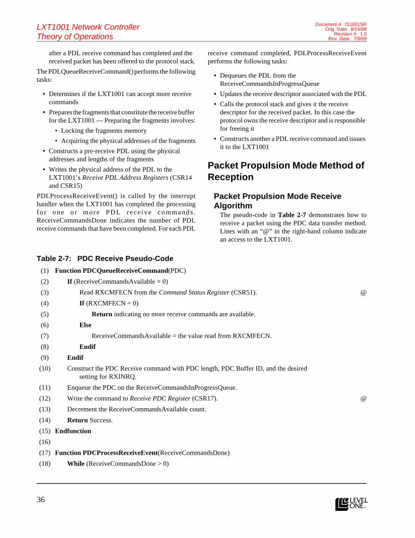
36l
LXT1001 Network ControllerTheory of Operations
Document #: IS1001SROrig. Date: 8/24/98
Revision #: 1.0Rev. Date: 7/9/99
Features (cont.)after a PDL receive command has completed and the received packet has been offered to the protocol stack.
The PDLQueueReceiveCommand() performs the followingtasks:
• Determines if the LXT1001 can accept more receive commands
• Prepares the fragments that constitute the receive buffer for the LXT1001 — Preparing the fragments involves:
• Locking the fragments memory
• Acquiring the physical addresses of the fragments
• Constructs a pre-receive PDL using the physical addresses and lengths of the fragments
• Writes the physical address of the PDL to the LXT1001’s Receive PDL Address Registers (CSR14 and CSR15)
PDLProcessReceiveEvent() is called by the interrupthandler when the LXT1001 has completed the processingf o r o n e o r m o r e P D L r e c e i v e c o m m a n d s .ReceiveCommandsDone indicates the number of PDLreceive commands that have been completed. For each PDL
receive command completed, PDLProcessReceiveEventperforms the following tasks:
• Dequeues the PDL from the ReceiveCommandsInProgressQueue
• Updates the receive descriptor associated with the PDL
• Calls the protocol stack and gives it the receive descriptor for the received packet. In this case the protocol owns the receive descriptor and is responsible for freeing it
• Constructs another a PDL receive command and issues it to the LXT1001
Packet Propulsion Mode Method of Reception
Packet Propulsion Mode Receive Algorithm
The pseudo-code in Table 2-7 demonstrates how toreceive a packet using the PDC data transfer method.Lines with an “@” in the right-hand column indicatean access to the LXT1001.
Table 2-7: PDC Receive Pseudo-Code
(1) Function PDCQueueReceiveCommand(PDC)
(2) If (ReceiveCommandsAvailable = 0)
(3) Read RXCMFECN from the Command Status Register (CSR51). @
(4) If (RXCMFECN = 0)
(5) Return indicating no more receive commands are available.
(6) Else
(7) ReceiveCommandsAvailable = the value read from RXCMFECN.
(8) Endif
(9) Endif
(10) Construct the PDC Receive command with PDC length, PDC Buffer ID, and the desired setting for RXINRQ.
(11) Enqueue the PDC on the ReceiveCommandsInProgressQueue.
(12) Write the command to Receive PDC Register (CSR17). @
(13) Decrement the ReceiveCommandsAvailable count.
(14) Return Success.
(15) Endfunction
(16)
(17) Function PDCProcessReceiveEvent(ReceiveCommandsDone)
(18) While (ReceiveCommandsDone > 0)

37
LXT1001 Network ControllerTheory of Operations
Document #: IS1001SROrig. Date: 8/24/98Revision #: 1.0Rev. Date: 7/9/99
l
(19) Dequeue the PDC from the ReceiveCommandsInProgressQueue.
(20) ReceiveHeader = the virtual address of the PDC.
(21) Set the PDC’s use count = 0.
(22) For (each packet in the PDC)
(23) Get a ReceivePacketDescriptor from the operating system.
(24) If (no ReceivePacketDescriptors are available)
(25) If (PDC’s use count is non-zero)
(26) Put the PDC on the PDCLoanedToProtocolList.
(27) Else
(28) Put the PDC on the ReceivePDCAvailableList.
(29) Endif
(30) Return indicating packets were lost due to lack of HOST resources.
(31) Endif
(32) PacketLength = the ReceiveHeader.LEN field.
(33) Set the packet length in the ReceivePacketDescriptor to PacketLength.
(34) Set the fragment count in the ReceivePacketDescriptor to 1.
(35) Set the first fragment virtual address in the ReceivePacketDescriptor to the packet’s first RXDATA byte in the PDC; i.e., the CurrentPacketaddress of the first byte past the packet’s receive header inthe PDC.
(36) Examine the receive status codes in the packet’s PDC receive header and update the ReceivePacketDescriptor as necessary.
(37) Advance the ReceiveHeader to the next packet in the PDC; i.e., the (sumof ReceiveHeader + PacketLength + size of the receive header) rounded up to the next QWORD boundary.
(38) Call the protocol stack to give it the ReceivePacketDescriptor.
(39) If (the protocol is not finished with the buffer)
(40) Increment the PDC’s use count.
(41) Endif
(42) Endfor
(43) If (PDC’s use count is not zero)
(44) Put the PDC on the PDCLoanedToProtocolList.
(45) Get another PDC from the ReceivePDCAvailableList
(46) Endif
(47) If (PDC pointer is not null)
(48) Call PDCQueueReceiveCommand(PDC) to queue up another receive command.
(49) If (the return code indicates no more receive commands are available)
(50) Put the PDC on the ReceivePDCAvailableList.
Table 2-7: PDC Receive Pseudo-Code – continued
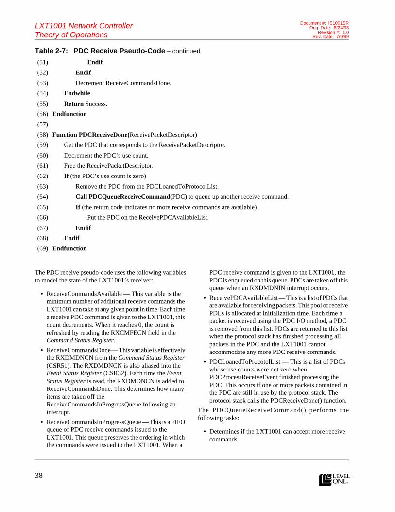
38l
LXT1001 Network ControllerTheory of Operations
Document #: IS1001SROrig. Date: 8/24/98
Revision #: 1.0Rev. Date: 7/9/99
Features (cont.)
The PDC receive pseudo-code uses the following variablesto model the state of the LXT1001’s receiver:
• ReceiveCommandsAvailable — This variable is the minimum number of additional receive commands the LXT1001 can take at any given point in time. Each time a receive PDC command is given to the LXT1001, this count decrements. When it reaches 0, the count is refreshed by reading the RXCMFECN field in the Command Status Register.
• ReceiveCommandsDone — This variable is effectively the RXDMDNCN from the Command Status Register (CSR51). The RXDMDNCN is also aliased into the Event Status Register (CSR32). Each time the Event Status Register is read, the RXDMDNCN is added to ReceiveCommandsDone. This determines how many items are taken off the ReceiveCommandsInProgressQueue following an interrupt.
• ReceiveCommandsInProgressQueue — This is a FIFO queue of PDC receive commands issued to the LXT1001. This queue preserves the ordering in which the commands were issued to the LXT1001. When a
PDC receive command is given to the LXT1001, the PDC is enqueued on this queue. PDCs are taken off this queue when an RXDMDNIN interrupt occurs.
• ReceivePDCAvailableList — This is a list of PDCs that are available for receiving packets. This pool of receive PDLs is allocated at initialization time. Each time a packet is received using the PDC I/O method, a PDC is removed from this list. PDCs are returned to this list when the protocol stack has finished processing all packets in the PDC and the LXT1001 cannot accommodate any more PDC receive commands.
• PDCLoanedToProcotolList — This is a list of PDCs whose use counts were not zero when PDCProcessReceiveEvent finished processing the PDC. This occurs if one or more packets contained in the PDC are still in use by the protocol stack. The protocol stack calls the PDCReceiveDone() function.
The PDCQueueReceiveCommand() performs thefollowing tasks:
• Determines if the LXT1001 can accept more receive commands
(51) Endif
(52) Endif
(53) Decrement ReceiveCommandsDone.
(54) Endwhile
(55) Return Success.
(56) Endfunction
(57)
(58) Function PDCReceiveDone(ReceivePacketDescriptor)
(59) Get the PDC that corresponds to the ReceivePacketDescriptor.
(60) Decrement the PDC’s use count.
(61) Free the ReceivePacketDescriptor.
(62) If (the PDC’s use count is zero)
(63) Remove the PDC from the PDCLoanedToProtocolList.
(64) Call PDCQueueReceiveCommand(PDC) to queue up another receive command.
(65) If (the return code indicates no more receive commands are available)
(66) Put the PDC on the ReceivePDCAvailableList.
(67) Endif
(68) Endif
(69) Endfunction
Table 2-7: PDC Receive Pseudo-Code – continued

39
LXT1001 Network ControllerTheory of Operations
Document #: IS1001SROrig. Date: 8/24/98Revision #: 1.0Rev. Date: 7/9/99
l
• Enqueues the PDC to the ReceiveCommandsInProgressQueue
• Writes the PDC’s buffer ID and length to the LXT1001’s Receive PDC Register (CSR17)
PDCProcessReceiveEvent() is called by the interrupthandler when the LXT1001 has completed the processingf o r o n e o r m o r e P D C r e c e i v e c o m m a n d s .ReceiveCommandsDone indicates the number of PDCreceive commands that have been completed. For each PDCreceive command completed, PDCProcessReceiveEventperforms the following tasks:
• Dequeues the PDC from the ReceiveCommandsInProgressQueue
• Parses the PDC packet for the beginning of each packet received into the PDC — For each packet in the PDC, it does the following:
• Allocates and initializes the receive descriptor to point to the data in the PDC and include the receive status of the packet
• Calls the protocol stack to give it the receive packet descriptor; in this case, the protocol stack either completely processes the packet before returning, or calls the PDCReceiveDone() at some later point in time to indicate it has finished processing the packet
• Maintains a use count for each PDC to keep track of how many packets within the PDC are in use by the protocol stack; PDCs whose use count is non-zero are added to the PDCLoanedToProcotolList
• Calls PDCQueueReceiveCommand() to issue another PDC receive command to the LXT1001
PDCReceiveDone() is called by the protocol stack toindicate it is finished processing a received packet. The usecount for the corresponding PDC is decremented. If the PDCuse count is zero, PDCReceiveDone() attempts to issueanother PDC receive command to the LXT1001.
Interrupt Processing
Event Status RegisterThe Event Status Register acts as an accumulator ofLXT1001 events. The LXT1001 tracks the followingcategories of events in the Event Status Register:
• Receive events
• Transmit events
• FIFO watermark events
• Timer events
As events occur, their corresponding event bits get set in theEvent Status Register. Event bits remain set until the registeris read by HOST software. When the Event Status Registeris read, the LXT1001 returns the current value of the registerto HOST software and then clears the register. Only the bitsthat are read are cleared. In other words, if HOST softwaredoes a byte access to the second byte in the Event StatusRegister, only that byte is cleared.
The Event Status Register has two special attributes. First,the high order byte of the register is actually an alias for theRXDMDNCN in the Command Status Register. When thisfield is read, the LXT1001 automatically clears it in boththe Event Status Register and the Command Status Register.
Second, a read of this register also causes the INENMS bitin the Interrupt Mask Register to be cleared if an interruptis pending (i.e., the LXT1001’s interrupt line is active). Thishas the effect of disabling the LXT1001’s ability to generatefurther interrupts. It is the responsibility of HOST softwareto re-enable the LXT1001’s ability to generate an interruptby setting the INENMS bit in the Interrupt Mask Register.
Interrupt Mask RegisterThe Interrupt Mask Register governs the LXT1001’s abilityto generate interrupts on the PCI bus. The INENMS bit inthe Interrupt Mask Register is the LXT1001’s masterenable/disable switch for interrupt generation. If INENMSis set, the LXT1001 has the capability to generate aninterrupt. If INENMS is clear, the LXT1001 cannot generatean interrupt.
All other bits in the Interrupt Mask Register determinewhich events in the Event Status Register generate aninterrupt. For each event bit in the Event Status Register,there is a corresponding interrupt mask bit in the InterruptMask Register. If the INENMS bit is set and the event bit’scorresponding mask bit is set in the Interrupt Mask Register,the LXT1001 generates an interrupt whenever the event bitgets set in the Event Status Register. Note that the InterruptMask Register does not prevent bits from being set in theEvent Status Register, it merely determines which eventscause the LXT1001 to generate an interrupt.

40l
LXT1001 Network ControllerTheory of Operations
Document #: IS1001SROrig. Date: 8/24/98
Revision #: 1.0Rev. Date: 7/9/99
Features (cont.)Interrupt HandlerThe pseudo-code in Table 2-8 demonstrates a typicalinterrupt handler for processing LXT1001 interrupts.
Table 2-8: Interrupt Handler Pseudo-Code
(1) Function InterruptHandler(PDC)
(2) Read the Interrupt Mask Register (CSR30) and save it in InterruptMask. @
(3) If (the INENMS bit is not set)
(4) Return indicating the CONTROLLER did not generate the interrupt.
(5) Endif
(6) Read the Event Status Register (CSR32). NOTE: The act of reading CSR32 will clear the INENMS bit in CSR30 if the CONTROLLER’s interrupt line is high when the read occurs. This has the effect of disabling the CONTROLLER’s ability to generate interrupts.
@
(7) EventStatus = EventStatus OR with the value just read from CSR30.
(8) If (using PDC or PDL method to receive packets)
(9) ReceiveCommandsDone = RXDMDNCN from EventStatus + ReceiveCommandsDone.
(10) Endif
(11) If ((EventStatus AND InterruptMask) is zero)
(12) Return indicating the CONTROLLER did not generate the interrupt.
(13) Endif
(14) If (required by the operating system)
(15) Issue an EOI to the interrupt CONTROLLER.
(16) Enable interrupts at the CPU.
(17) Endif
(18) While (EventStatus AND InterruptMask) is not zero)
(19) If (using PDC method for receiving packets)
(20) Call PDCProcessReceiveEvent(ReceiveCommandsDone). See Table 2-7
@
(21) Else If (using PDL method for receiving packets)
(22) Call PDLProcessReceiveEvent(ReceiveCommandsDone). See Table 2-6
@
(23) Else using PIO method for receives
(24) If ((EventStatus AND RXIN) is not zero)
(25) Call PIOProcessReceiveEvent(). See Table 2-5 @
(26) Endif
(27) Endif
(28) If ((EventStatus AND TXDMDNIN) is not zero)
(29) TransmitCommandsDone = Read TXDMDNCN from the Command Status Register (CSR51).
@
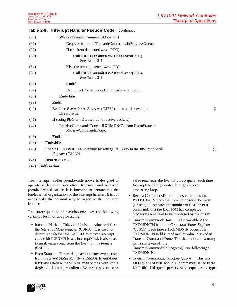
41
LXT1001 Network ControllerTheory of Operations
Document #: IS1001SROrig. Date: 8/24/98Revision #: 1.0Rev. Date: 7/9/99
l
The interrupt handler pseudo-code above is designed tooperate with the initialization, transmit, and receivedpseudo defined earlier. It is intended to demonstrate thefundamental organization of the interrupt handler. It is notnecessarily the optimal way to organize the interrupthandler.
The interrupt handler pseudo-code uses the followingvariables for interrupt processing:
• InterruptMask — This variable is the value read from the Interrupt Mask Register (CSR30). It is used to determine whether the LXT1001’s master interrupt enable bit INENMS is set. InterruptMask is also used to mask values read from the Event Status Register (CSR32).
• EventStatus — This variable accumulates events read from the Event Status Register (CSR30). EventStatus is bitwise ORed with the initial read of the Event Status Register in InterruptHandler(). EventStatus is set to the
value read from the Event Status Register each time InterruptHandler() iterates through the event processing loop.
• ReceiveCommandsDone — This variable is the RXDMDNCN from the Command Status Register (CSR51). It indicates the number of PDC or PDL commands that the LXT1001 has completed processing and need to be processed by the driver.
• TransmitCommandsDone — This variable is the TXDMDNCN from the Command Status Register (CSR51). Each time a TXDMDNIN occurs, the TXDMDNCN field is read and its value is saved in TransmitCommandsDone. This determines how many items are taken off the TransmitCommandsInProgressQueue following a TXDMDNIN.
• TransmitCommandsInProgressQueue — This is a FIFO queue of PDL and PDC commands issued to the LXT1001. This queue preserves the sequence and type
(30) While (TransmitCommandsDone > 0)
(31) Dequeue from the TransmitCommandsInProgressQueue.
(32) If (the item dequeued was a PDC)
(33) Call PDCTransmitDMADoneEvent(PDC). See Table 2-4
(34) Else the item dequeued was a PDL
(35) Call PDLTransmitDMADoneEvent(PDL). See Table 2-4.
(36) Endif
(37) Decrement the TransmitCommandsDone count.
(38) Endwhile
(39) Endif
(40) Read the Event Status Register (CSR32) and save the result in EventStatus.
@
(41) If (using PDC or PDL method to receive packets)
(42) ReceiveCommandsDone = RXDMDNCN from EventStatus + ReceiveCommandsDone.
(43) Endif
(44) Endwhile
(45) Enable CONTROLLER interrupt by setting INENMS in the Interrupt Mask Register (CSR30).
@
(46) Return Success.
(47) Endfunction
Table 2-8: Interrupt Handler Pseudo-Code – continued

42l
LXT1001 Network ControllerTheory of Operations
Document #: IS1001SROrig. Date: 8/24/98
Revision #: 1.0Rev. Date: 7/9/99
Features (cont.)of transmit commands issued to the LXT1001. When a transmit PDL or PDC command is given to the LXT1001, the PDL or PDC is enqueued on this queue. Items are taken off this queue when a TXDMDNIN interrupt occurs.
InterruptHandler() is called by the operating system whenthe interrupt occurs on the interrupt line for which thehandler is registered. The interrupt handler first determineswhether the LXT1001 generated the interrupt. To determinethis, it reads the Interrupt Mask Register (CSR32) andchecks the INENMS bit. If INENMS is clear, the LXT1001did not generate the interrupt so the interrupt handler exits.If the INENMS is set, HOST software must then read theEvent Status Register and bitwise AND the value read withthe value read from the Interrupt Mask Register. If the resultis of this operation is non-zero, the LXT1001 generated theinterrupt, otherwise some other device generated theinterrupt.
It is important to note that the value read from the EventStatus Register, when determining whether the LXT1001generated the interrupt, must be saved even if the LXT1001did not generate the interrupt. This is necessary because ofthe clear after read nature of the Event Status Register. Thevalue read from the Event Status Register is bitwise ORedwith the EventStatus variable, even when the LXT1001 didnot generate the interrupt. This prevents the loss ofLXT1001 events for which the LXT1001 is not configuredto generate an interrupt. For similar reasons, if the driver isusing PDL or PDC mode to receive frames, theRXDMDNCN read from the Event Status Register is addedto ReceiveCommandsDone.
Once the InterruptHandler() has determined the LXT1001generated an interrupt, it proceeds to the event processingloop. For each iteration of the loop, the appropriate eventprocessing occurs for each bit set in EventStatus. At thebottom of the loop, the Event Status Register is read againand EventStatus and ReceiveCommandsDone are updated.The InterruptHandler() continues looping until EventStatusand ReceiveCommandsDone are 0.
Note that this implementation of the interrupt handlerchecks to see the type of receive I/O method being used forreceive, because the driver implements all three modes.Typically, a driver implements a single receive I/O methodthat is optimal for the target operating system. In this case,the check to determine the receive I/O method being usedis unnecessary.
VLAN SupportThe LXT1001 provides the following VLAN IEEE 802.1Qsupport with the following functionality:
• VLAN tag insertion
• VLAN tag removal
• VLAN tag packet filtering
A VLAN tag is 4 bytes long and consists of a 2-byte protocolID field followed by a 2-byte tag control information (TCI)field. The TCI field is divided into a 3-bit user priority field,a 1-bit canonical format identifier (CFI) field, and a 12-bitVLAN Identifier (VLID) field. VLAN tag headers arelocated at bytes offset 12 – 15 in a packet’s MAC header(i.e., between the source address field and length/type field).The protocol ID field is used by the LXT1001 for VLANtag insertion and filtering. The LXT1001 uses the value0x8100 for the protocol ID field when performing VLANtag insertion and filtering. The LXT1001 also provides a16-entry table for TCIs. The VLAN Tag TCI table is usedby the LXT1001 for VLAN tag insertion and filtering.HOST software adds and deletes entries in the table usingthe VLAN Tag TCI Table Register.
The VLEN bit in Mode Register – 1 is the masterenable/disable bit for the LXT1001’s VLAN support. Bydefault the VLEN bit is clear, meaning the LXT1001’sVLAN support is disabled. When the VLEN bit is set, theLXT1001’s VLAN support is enabled and HOST softwarecan then independently configure and enable the threefunctions described above.
The LXT1001’s VLAN tag insertion function can operatein two different modes: global and per-packet. In globalmode, the LXT1001 inserts a VLAN tag header in allpackets transmitted. The LXT1001 constructs and inserts aVLAN tag using the value of 0x8100 for the protocol IDand the value in the first (0) entry of the VLAN Tag TCITable. HOST software enables the global mode of VLANtag insertion by setting the VLEN and VLISGB bit in ModeRegister – 1.
Per-packet VLAN tag insertion gives HOST software thecapability to request the VLAN tag insertion on a per-packetbasis. First, the VLEN bit must be set. HOST software thensets the VLIS bit in the packet’s transmit header to indicatethe VLAN tag header is to be inserted. When VLIS is set,HOST software must also set the VLTBIX field in thepacket’s transmit header. The VLTBIX field is an index intothe VLAN Tag TCI Table. The LXT1001 constructs andinserts the VLAN tag header using the value of 0x8100 forthe protocol ID and the TCI information using the VLANTag TCI Table entry specified by VLTBIX.

43
LXT1001 Network ControllerTheory of Operations
Document #: IS1001SROrig. Date: 8/24/98Revision #: 1.0Rev. Date: 7/9/99
l
Figure 2-5: VLAN Header Format
Per-packet VLAN tag insertion gives HOST software thecapability to request the VLAN tag insertion on a per-packetbasis. First, the VLEN bit must be set. HOST software thensets the VLIS bit in the packet’s transmit header to indicatethe VLAN tag header is to be inserted. When VLIS is set,HOST software must also set the VLTBIX field in thepacket’s transmit header. The VLTBIX field is an index intothe VLAN Tag TCI Table. The LXT1001 constructs andinserts the VLAN tag header using the value of 0x8100 forthe protocol ID and the TCI information using the VLANTag TCI Table entry specified by VLTBIX.
HOST software can mix the global and per-packet taginsertion modes by setting the VLISGB in Mode Register –1 and then setting the VLIS bit in the transmit header ofselected packets. In this case, the VLIS prevails and theLXT1001 constructs and inserts a VLAN tag header usingthe per-packet method.
The LXT1001’s VLAN tag removal support can be enabledby setting the VLEN and VLRMID bits in Mode Register –1. When enabled, the LXT1001 parses inbound packets fora VLAN tag header. If a VLAN tag header is found, it isremoved from the packet prior to being put into the RXFIFORX FIFO. Consequently, the VLAN tag is never seenby HOST software. When the LXT1001 removes a VLANtag header from a packet, the CRC is always removed too,regardless of the state of the PACREN bit in Mode Register– 1. The CRC is removed because it is no longer valid sincethe VLAN tag is included in the CRC calculation.
Finally, the LXT1001 can filter inbound packets thatcontain a VLAN tag header. The VLAN tag filter affectsreceived packets that contain a VLAN header. Whenconfigured by HOST software, the VLAN tag filterforwards packets containing a VLAN header whoseprotocol ID equals 0x8100 and whose VLID field matchesthe VLID of an entry the VLAN Tag Table. This feature isenabled by setting the VLTBEN bit in Mode Register – 1.When the VLAN tag filter is enabled, the LXT1001provides additional receive status information in thepacket’s PIO/PDL/PDC receive header. In particular, theLXT1001 sets the VLHT bit in the receive header of packetsthat contain a VLAN tag header that passed the VLAN tagfilter. The LXT1001 also puts the index of the matchingVLAN Tag TCI Table entry in VLTBIX field of the receiveheader.
TCP/IP Checksum SupportThe LXT1001 provides advanced capabilities forprocessing TCP/IP checksums. The LXT1001 can verify IP,TCP, and UDP checksums during packet reception. TheLXT1001 overlaps the checksum processing with packetreception. The LXT1001’s TCP/IP checksum capabilitiesincrease system performance by overlapping checksumprocessing with the packet reception and by relieving theHOST CPU of the checksum verification tasks.
There are three bits in Mode Register – 2 that enable/disablethe LXT1001’s ability to verify TCP/IP checksums inreceived packets. Setting the RXIPCKEN bit in ModeRegister – 2 causes the LXT1001 to verify the IP checksumfor all inbound packets containing an IP header. If thechecksum fails, the LXT1001 sets the IPCKER status bit inthe packet’s PIO/PDL/PDC receive header. If the checksumis valid or the packet does not contain an IP header, theIPCKER bit will be clear in the receive header. TheLXT1001 handles checksums for TCP and UDP in a similarmanner. The RXTPCKEN and RXUPCKEN bits in ModeRegister – 2 enable the TCP and UDP checksumverification. The TPCKER and UPCKER bits in thepacket’s PIO/PDL/PDC receive header will be set if a TCPor UDP checksum error occurs.
Finally, the action the LXT1001 takes for packetscontaining TCP/IP checksum errors is governed by thePACKEREN bit in Mode Register – 2. When PACKERENis set, received packets containing TCP/IP checksum errorsare passed to HOST software. When clear, the packets arediscarded by the LXT1001.
EEPROM SupportThe LXT1001 provides a 93C46 compatible EEPROMinterface. EEPROM is used as a convenient nonvolatilestore of LXT1001 parameters. In particular, EEPROM isused to store the LXT1001’s Universally AdministeredAddress (UAA), PCI configuration space defaults, andoverrides for some CSR’s default values. EEPROM can alsobe used by HOST software as a nonvolatile store forsoftware configuration parameters. Typically, EEPROM isaccessed following a LXT1001 reset or by HOST diagnosticsoftware.
31 16 15 13 12 11 00
Protocol ID (PID) UserPriority
CFI
VLAN Identifier (VLID)

44l
LXT1001 Network ControllerTheory of Operations
Document #: IS1001SROrig. Date: 8/24/98
Revision #: 1.0Rev. Date: 7/9/99
Features (cont.)Following a LXT1001 hard or soft reset, the LXT1001 readsEEPROM and overwrites the CSRs. See Figure 6-1 todetermine which CSRs are overwritten following a reset.When reloading CSRs from EEPROM, the LXT1001calculates a 32-bit checksum and compares the checksumagainst the checksum value stored in EEPROM. If anincorrect checksum is obtained, the LXT1001 will setEECKSMER in the EEPROM register. If this bit is set, it isthe responsibility of the HOST software to restore thedefault values to the CSRs.
HOST software can access EEPROM using the EEPROMand EEPROM Data Registers on an individual DWORDbasis. Although EEPROM is organized internally as 16-bitwords, the LXT1001 presents the EEPROM contents as32-bit DWORDs to HOST software. The LXT1001accomplishes this by combining two EEPROM 16-bitwords into a 32-bit big endian DWORD.
Since the LXT1001 can operate without EEPROM, HOSTsoftware must determine if EEPROM is present prior toaccessing it. If EEPROM is present, the LXT1001 sets theEEPMPN bit in the EEPROM Register. To read a value fromEEPROM, HOST software sets EEAD in the EEPROMRegister to the index of the EEPROM DWORD to be read.It then sets EERDCM and EESL bits in the EEPROMRegister to initiate the read command. HOST software mustthen poll the EESL bit to await the completion of theEEPROM read command. The LXT1001 clears the EESLbit after completing the read command. HOST software canthen read the value from the EEPROM Data Register.
To write a value to EEPROM, HOST software first writesthe value to be written to EEPROM to the EEPROM DataRegister. Next, HOST software sets EEAD in the EEPROMRegister to the index of the EEPROM DWORD to bewritten. It then sets EEWTCM and EESL bits in theEEPROM Register to initiate the write command. HOSTsoftware must then poll the EESL bit to await the completionof the EEPROM write command. The LXT1001 clears theEESL bit after completing the write command. If HOSTsoftware writes a value in EEPROM, it must also recalculateand write the new checksum value to EEPROM.
Expansion ROM SupportThe LXT1001 provides an expansion ROM interface. Ifpresent, the expansion ROM contains an executable imagethat is invoked by the HOST system’s BIOS during the bootprocess. An expansion ROM attached to the LXT1001typically contains an executable image that allows thenetwork connection to be the boot device (i.e., the devicefrom which the operating system is loaded). The LXT1001
expansion ROM interface supports EPROM and flashdevices.
HOST BIOS detects the presence and size of the expansionROM using the Expansion ROM Base Address Register atoffset 30h in the PCI Configuration space. If the expansionROM is present, HOST BIOS maps the expansion ROMinto the HOST’s memory address space by writing at thebase address to the Expansion ROM Base Address Register.Due to the slow access times for expansion ROM devices,BIOS shadows (i.e., copies) the expansion ROM image intosystem RAM. When BIOS executes the expansion ROMimage, it executes the expansion ROM image copied toRAM.
Once BIOS has mapped expansion ROM into HOSTmemory address space, HOST software can read theexpansion ROM just as it reads any other memory location.HOST software can read the expansion ROM using 8-, 16-,and 32-bit memory accesses. Due to the slow access timesof most flash devices, however, HOST software shouldavoid 32-bit read accesses after system initialization timeto ensure the PCI 16- and 8-clock bus holding rules are notviolated. The PCI specification allows the bus holding rulesto be violated during system initialization so expansionROMs can be shadowed to system RAM using 32-bitaccesses.
If the expansion ROM is a flash device, HOST software canalso perform memory writes to the device. HOST softwarecan determine whether a flash device is present by checkingthe FLPN bit in the EEPROM Register. To enable writingto the flash device, HOST software must first set theFLWTEN bit in the EEPROM Register. HOST softwarethen writes to the flash device using 8-bit accesses. The hostsoftware must delay at least 1 ms between each byte writtento the flash. If either the FLPN or FLWTEN bits are clear,write accesses to the expansion ROM do not change thecontents of the expansion ROM.
Magic Packet Wake UpThe LXT1001 supports wake up via Magic Packettechnologyin systems that support PCI power management.Magic Packet technology, developed by Advanced MicroDevices, allows a computer system in a low or no powerstate to be restored to a full power state remotely vianetwork. This is accomplished by sending a packetcontaining a specific data sequence. This is referred to as aMagic Packet data sequence. The LXT1001 requires thepower to be supplied to the LXT1001 via the PCI bus,however, all other components in the computer system canbe in a low or no power state.

45
LXT1001 Network ControllerTheory of Operations
Document #: IS1001SROrig. Date: 8/24/98Revision #: 1.0Rev. Date: 7/9/99
l
In order for a packet to be considered a Magic Packet datasequence, it must meet the following criteria:
• It must contain a valid 14-byte MAC header; i.e., 6-byte destination address, 6-byte source address, and 2-byte length/type field. The destination address can be a unicast, multicast, or broadcast address.
• The packet must be have a valid CRC and be at least the minimum frame size in length.
• The LLC data portion of the packet must contain a 6-byte preamble 0xFF, followed by 16 repetitions of the LXT1001’s MAC address. The preamble and MAC address repetitions must be contiguous. The sequence itself can begin at any offset within the LLC data.
It is necessary to permit Magic Packet data sequences tocontain a multicast or broadcast destination address toensure the computer is reachable through routers. Someprotocols cause routers to discard the unicast MAC addressof a computer from their routing tables when the computeris powered off. In such instances, a Magic Packet datasequence containing a unicast destination address can notbe routed to the computer. A Magic Packet data sequencecontaining a broadcast or multicast address, however, canalways be routed to a computer and, therefore, allow thecomputer to be successfully awakened.
The LXT1001 is put into Magic Packet mode by setting theMGPKEN bit in Mode Register – 1. When a Magic Packetdata sequence is received, the RXMGPKIN bit is set in theEvent Status Register. If the RXMGPKMS and INENMSbit are set in the Interrupt Mask Register, an interrupt on thePCI bus is generated.
The reception of a Magic Packet data sequence can alsocause the system to wake up via the power managementevent (PME) pin. In a computer that supports PCI powermanagement, assertion of the PME causes the system toreturn to a fully powered state. The following sectiondiscusses how to configure the LXT1001 such that a MagicPacket data sequence results in the PME pin being asserted.
PCI Power ManagementThe LXT1001 complies with the PCI Power ManagementInterface Specification, Rev. 1.0. This specification defines
a set of PCI configuration space registers used to query aPCI device’s power management capabilities, and queryand set its power management state. Additionally, a PMEpin is defined for signaling wake up events to the computersystem. System-level software uses these interfaces tomanage the power state of the PCI devices. Refer to the PCIPower Management Specification, Rev. 1.0, for a detaileddescription of these registers and pin.
The LXT1001 supports power management in the followingmanner:
• It supports device power states D0, D3hot, and D3cold.
• No explicit action is taken to power down blocks within the LXT1001. Power savings occur because the PCI block and MAC will not put data into the Tx and RX FIFOs during the D3hot state.
• PME assertion can occur due to Magic Packet data sequence frame recognition during either the D0 or D3hot power states.
• PCI Configuration space accesses are enabled while in the D0 and D3hot power state.
• Interrupts, PCI memory transactions, and PCI I/O transactions are disabled in D3hot.
• The Power Management Register Block is implemented in the PCI configuration space.
The PME_En bit in the Power Management Control/StatusRegister (PMCSR) governs whether or not a Magic Packetevent results in the PME pin being asserted. The MGPKENenable bit in CSR 00 enables the Magic Packet detectionlogic in the MAC. For a Magic Packet data sequence to bedetected and cause PME to be asserted, both the MGPKENbit in CSR 00 and the PME_En bit in PMCSR must be set.When these bits are set and a Magic Packet data sequenceis received, the PME pin is asserted and the LXT1001 resetsitself as if a PCI RST had occurred, with one exception: thePME context is preserved across the reset. The PME contextis defined as the state of all bits in the Power ManagementControl/Status Register and the state of the PME pin. ThePME will remain asserted until either the PME_Status bitor the PME_En bit is cleared by software.

46l
LXT1001 Network ControllerTheory of Operations
Document #: IS1001SROrig. Date: 8/24/98
Revision #: 1.0Rev. Date: 7/9/99
Features (cont.)
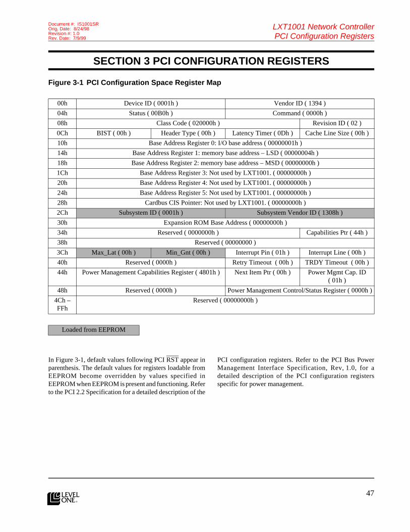
47
LXT1001 Network ControllerPCI Configuration Registers
Document #: IS1001SROrig. Date: 8/24/98Revision #: 1.0Rev. Date: 7/9/99
l
SECTION 3 PCI CONFIGURATION REGISTERS
Figure 3-1 PCI Configuration Space Register Map
In Figure 3-1, default values following PCI RST appear inparenthesis. The default values for registers loadable fromEEPROM become overridden by values specified inEEPROM when EEPROM is present and functioning. Referto the PCI 2.2 Specification for a detailed description of the
PCI configuration registers. Refer to the PCI Bus PowerManagement Interface Specification, Rev, 1.0, for adetailed description of the PCI configuration registersspecific for power management.
00h Device ID ( 0001h ) Vendor ID ( 1394 )
04h Status ( 00B0h ) Command ( 0000h )
08h Class Code ( 020000h ) Revision ID ( 02 )
0Ch BIST ( 00h ) Header Type ( 00h ) Latency Timer ( 0Dh ) Cache Line Size ( 00h )
10h Base Address Register 0: I/O base address ( 00000001h )
14h Base Address Register 1: memory base address – LSD ( 00000004h )
18h Base Address Register 2: memory base address – MSD ( 00000000h )
1Ch Base Address Register 3: Not used by LXT1001. ( 00000000h )
20h Base Address Register 4: Not used by LXT1001. ( 00000000h )
24h Base Address Register 5: Not used by LXT1001. ( 00000000h )
28h Cardbus CIS Pointer: Not used by LXT1001. ( 00000000h )
2Ch Subsystem ID ( 0001h ) Subsystem Vendor ID ( 1308h )
30h Expansion ROM Base Address ( 00000000h )
34h Reserved ( 0000000h ) Capabilities Ptr ( 44h )
38h Reserved ( 00000000 )
3Ch Max_Lat ( 00h ) Min_Gnt ( 00h ) Interrupt Pin ( 01h ) Interrupt Line ( 00h )
40h Reserved ( 0000h ) Retry Timeout ( 00h ) TRDY Timeout ( 00h )
44h Power Management Capabilities Register ( 4801h ) Next Item Ptr ( 00h ) Power Mgmt Cap. ID ( 01h )
48h Reserved ( 0000h ) Power Management Control/Status Register ( 0000h )
4Ch – FFh
Reserved ( 00000000h )
Loaded from EEPROM
48l
LXT1001 Network ControllerPCI Configuration Registers
Document #: IS1001SROrig. Date: 8/24/98
Revision #: 1.0Rev. Date: 7/9/99
Features (cont.)

49
LXT1001 Network ControllerCommand and Status Registers
Document #: IS1001SROrig. Date: 8/24/98Revision #: 1.0Rev. Date: 7/9/99
l
SECTION 4 COMMAND AND STATUS REGISTERS
This section presents the details of the register interface tothe LXT1001. The information is arranged in tabular formwith the following format:
The individual columns of the table have the followingsignificance:
Bit Field — This column indicates the start and end bitposition of a field of bits. The most significant bit positionis listed first, followed by a colon character (“:”) and theleast significant bit position of the field within the register.For single bit fields, the position number is listed withoutthe ensuing colon and end bit identifier. For example, 20:17identifies a bit field that is 4 bits wide. The most significantbit is bit 20, and the least significant bit is bit 17. Bit 20represents a value of 23 and bit 17 represents a value of 20.
Type — The type field can contain a series of single letteridentifiers that denote the behavioral attributes of specificbit fields within a register. The identifiers are concatenatedtogether to denote the attributes that apply to the given bitfield. Acceptable type designators are:
• R — Read.
• W — Write.
• A — Auto Clear. (Auto Clear implies the field is readable.)
• C — Clear after read.
E2 — This column is used to denote if the field’s initialvalue is to be obtained from the serial EEPROM. If a field’sinitial value is obtained from EEPROM, a check mark (√)is placed in this column. Otherwise, an x mark (x) is placedin the column.
Mnemonic — Values in this column provide symbolicnames for the corresponding field. The mnemonics areconstructed to aid in the pronunciation of the field’s name.Generally, mnemonics are two characters in length and areconcatenated to form a single symbol. For example, themnemonic BFAD is comprised of the two sub-mnemonicsBF which represents the word buffer and AD whichrepresents the word address. Together, they symbolize abuffer address. Each mnemonic used in this document islisted in the Glossary, Section 7.
Default Value — The Default Value column denotes thevalue the register will assume once the LXT1001 has beenpowered up and placed into its start state. Fields that areinitialized from EEPROM also have a default value. In thesecases, the default value is applied prior to EEPROM beingread. This method provides a means for the chip to initializeeven if the EEPROM should fail, or if an EEPROM is notdesired.
Description — The Description column provides a briefexplanation of the field and its usage.
One important aspect of the register interface is that it isinherently a 32-bit interface. This is due to the PCI’s use ofa 32-bit I/O path despite its support for 64-bit data andaddress paths for memory cycles. The net result of thisdesign attribute of the PCI bus is that 64-bit address registersimplemented in the LXT1001 must be accessed with two32-bit I/O cycles. To avoid race conditions when writing to64-bit registers, a policy is adopted by the LXT1001whereby it only examines the contents of a 64-bit registeronce the least significant DWORD (LSD) is written. To helpclarify the policy, consider the case where a 64-bit registeris maintained by the LXT1001 and is updated by HOSTsoftware. The HOST begins by writing the MSD register.After the MSD is written, the HOST writes the LSD. Thispolicy brings about two noteworthy behaviors. First, iteliminates the potential for a race condition between theHOST and the LXT1001. Second, it provides a means bywhich 64-bit registers can be updated with single 32-bitwrites. For example, when initializing the PDC BufferAddress Table (which requires 64-bit physical addresses forPDC data buffers), HOST software can write the contentsof the Transmit PDC Buffer Address MSD Register prior toinitializing the table. Subsequently, the HOST software canconsecutively write the LSDs of the PDC buffer addressesto the register without further manipulation of the MSDregister. This technique works because the MSDs of theaddresses of PDC data buffers are almost certainly the samefor all PDC data buffers allocated by HOST software. Oncethis MSD is written to the Transmit PDC Buffer AddressMSD Register, it is read by the LXT1001 each time the LSDregister is written.
Bit Field Type E2 Mnemonic Default Value Description

50l
LXT1001 Network ControllerCommand and Status Registers
Document #: IS1001SROrig. Date: 8/24/98
Revision #: 1.0Rev. Date: 7/9/99
Features (cont.)CSR 00 Mode Register – 1
31
30
29
28
27
26
25
24
23
22
21
20
19
18
17
16
15
14
13
12
11
10
09
08
07
06
05
04
03
02
01
00
LNCKEN
USPI
MD1
USPI
MD0
VLISGB
VLRMID
VLTBEN
VLEN
SERECL
RXFLCTEN
MGMCBCEN
MGPKEN
RESRVD
TXCREN
PAERPKEN
PACREN
SERECL
LGPKEN
UCEN
POEN
BCEN
MCEN
RXEN
TXEN
SERECL
RESRVD
TXPPEN
GMSTPOEN
RXTRPR
RESRVD
RESRVD
SWRE
SERECL
Bit Field Type E2 Mnemonic
Default Value Description
0 W x SERECL 0 Set/Reset Control — Set/reset control bit for bits[7:1]
1 WA x SWRE 0 Soft Reset — When set, the LXT1001 resets all internal registers with the exception of the PCI configuration registers. This includes the Transmit PDC Buffer, Receive PDC Buffer, Address Table, VLAN Tage Control Table, etc. This bit remains set for the duration of the reset. Upon completion of the reset, the LXT1001 automatically clears this bit. HOST software can poll this bit to determine when the reset has completed.
2 N/A x RESRVD N/A Reserved
3 N/A x RESRVD N/A Reserved
4 RW √ RXTRPR 0 Receive/Transmit Priority — Bus arbitration priority between receive and transmit. When set, the LXT1001 uses a round-robin arbitration scheme between receive and transmit (equal priority). When reset, receive has an 8:1 priority over transmit.
5 RW √ GMSTPOEN 0 G/MII Status Polling Enable — When set, the LXT1001 periodically queries the PHY to determine if a status change has occurred. If a status change has occurred, the LXT1001 sets the PHLASTIN bit in the Event Status Register. When clear, the LXT1001 does not query the PHY for a status change. HOST software can perform this operation manually via the G/MII PHY Access Register.
6 RW √ TXPPEN 1 Transmit Packet Pad Enable — When set, the LXT1001 pads a transmit packet to the minimum frame size. The minimum frame size for ethernet is 60 bytes, excluding the CRC and VLAN tag field.
7 N/A √ RESRVD N/A Reserved
8 W x SERECL 0 Set/Reset Control — Set/reset control bit for bits[15:9]

51
LXT1001 Network ControllerCommand and Status Registers
Document #: IS1001SROrig. Date: 8/24/98Revision #: 1.0Rev. Date: 7/9/99
l
9 RW x TXEN 0 Transmitter Enable — When set, the LXT1001 can perform transmits. When reset, the LXT1001 will not perform transmits. If a packet transmission is in progress, the LXT1001 will complete it and stop.
10 RW x RXEN 0 Receiver Enable — When set, the LXT1001 can perform receives. When reset, the LXT1001 will not perform receives. If a packet reception is in progress, the LXT1001 will complete it and stop.
11 RW x MCEN 0 Multicast Enable — When set, the LXT1001 will accept a packet with a multicast destination address that matches in the Multicast Hash Table Register.
12 RW x BCEN 0 Broadcast Enable — When set, the LXT1001 will accept a packet with a broadcast destination address.
13 RW x POEN 0 Promiscuous Mode Enable — When set, all packets will pass the LXT1001’s destination address filter, regardless of the settings of UCEN, MCEN, and BCEN. Packets, however, are still subject to the LXT1001’s other reception filters. To cause the LXT1001 to accept all packets without modification, HOST software must set the POEN, PAERPKEN, and PACREN bits in Mode Register – 1, and clear the VLTBEN, VLRMID, and RMPPEN bits in Mode Register – 1.
14 RW x UCEN 1 Unicast Mode Enable — When set, the LXT1001 will accept frames in which the destination address matches the LXT1001’s unicast address; i.e., the address set in the LAN Physical Address Register (CSR 42). When reset, frames with the destination addresses matching the station’s unicast address will not be accepted.
15 RW √ LGPKEN 0 Large Packet Enable — This bit determines how the LXT1001 processes packets that exceed the maximum packet size. When the LGPKEN bit set, the LXT1001 receives the packets that exceed the maximum packet size into the RX FIFO and sets the LGPK bit in the receive header. The Large Packet Count is incremented.When the LGPKEN bit is clear, the LXT1001 treats packets that exceed the maximum packet size as an errored packet. If the PAERPKEN bit is clear, the LXT1001 discards the packet. If the PAERPKEN bit is set, the LXT1001 receives the packet into the FIFO and sets the LGPK and ERROR bits in the receive header. Regardless of the state of PAERPKEN, the LXT1001 increments the Large Packet Count and Errored Packet Count.The maximum packet size used by the LXT1001 varies depending on the state of the VLEN bit. If VLEN is clear, the maximum packets size is 1518 bytes (including CRC). If VLEN is set, the maximum packet size is increased to 1522 bytes to allow for the 4-byte VLAN header.
Bit Field Type E2 Mnemonic
Default Value Description

52l
LXT1001 Network ControllerCommand and Status Registers
Document #: IS1001SROrig. Date: 8/24/98
Revision #: 1.0Rev. Date: 7/9/99
Features (cont.)16 RW x SERECL 0 Set/Reset Control — Set/reset control bit for bits[23:17]
17 RW x PACREN 0 Pass CRC Enable — When set, this bit indicates to the LXT1001 that the HOST software wishes to receive each frame’s CRC field. On reception, the only time this bit is defined, the inbound frame’s CRC field is transferred to receive buffers as it appears on the wire. Receive buffers are expected to be sufficiently large to accommodate the CRC. If not, a HOST buffer overflow error occurs.Regardless of the state of PACREN, the LXT1001 does not pass the CRC of packets from which it has removed the packet padding or a VLAN header. Since these fields are included in the CRC calculation, the CRC is no longer valid after the LXT1001 has removed them. Therefore, the LXT1001 does not pass the CRC in this case.
18 RW x PAERPKEN 0 Pass Errored Packet Enable — When set, this bit indicates to the LXT1001 that the HOST software wishes to receive errored packets. The errored packets are deposited (as best they can be) into HOST receive buffers and appropriate error bits are set in the receive header status fields.
19 RW x TXCREN 1 Transmit CRC Enable — When set, the LXT1001 will generate and append a CRC to transmitted packets. When clear, the LXT1001 does not generate or append the CRC to transmitted packets. Clearing the TXCREN bit can conflict and cause undefined behavior when other mode settings that cause the LXT1001 to insert or modify packet data prior to the packets transmission. In particular, enabling the padding, VLAN tag insertion, or TCPIP checksum features when the TXCREN bit is clear, results in the packet being transmitted with a invalid CRC.
20 N/A x RESRVD N/A Reserved
21 RW √ MGPKEN 0 Magic Packet Enable — This bit enables the LXT1001’s ability to recognize a Magic Packet recognition and generate a wake up signal.
22 RW √ MGMCBCEN 0 Magic Packet Multicast/Broadcast Enable — When clear, the LXT1001 only accepts Magic Packet data sequences with a destination address that matches the LAN Physical Address CSR. When this bit is set, the LXT1001 accepts Magic Packet data sequences whose destination address is a unicast, multicast address enabled via the Multicast Hash Table Register, or is an all stations broadcast.
Bit Field Type E2 Mnemonic
Default Value Description

53
LXT1001 Network ControllerCommand and Status Registers
Document #: IS1001SROrig. Date: 8/24/98Revision #: 1.0Rev. Date: 7/9/99
l
23 RW √ RXFLCTEN 1 Receive Flow Control Enable — This bit enables the LXT1001’s ability to detect and act upon the reception of a MAC Control PAUSE frame. When this bit is set and the link is a full-duplex connection, the LXT1001 will disable the transmitter when a MAC Control PAUSE frame is received. The LXT1001 will re-enable the transmitter after the duration of time specified in the PAUSE frame has elapsed. If another PAUSE frame is received before time has elapsed, the LXT1001 will reset its timer to the value specified in the subsequent PAUSE frame.When clear, the LXT1001 will ignore PAUSE frames.
24 W x SERECL 0 Set/Reset Control — Set/reset control bit for bits[31:25].
25 RW √ VLEN 0 VLAN Enable — When set, the LXT1001’s VLAN support is enabled. When clear, VLAN support is disabled.
26 RW √ VLTBEN 0 VLAN Tag Table Enable — This bit enables/disables the LXT1001’s VLAN receive filter. The VLAN receive filter is applied to packets that contain a VLAN header and have already passed the destination address filter. When this bit is set, the LXT1001 only accepts packets whose VLAN IDs are found in the VLAN register table. If VLTBEN is clear, the LXT1001 accepts all VLAN frames that pass the destination address filter.
27 RW √ VLRMID 0 VLAN Remove ID — When set, the LXT1001 removes the VLAN header from received packets. When clear, the LXT1001 does not remove the VLAN header from packets.
28 RW √ VLISGB 0 VLAN Insert Global — When set, the LXT1001 inserts the global VLAN header prior to transmitting a packet. The VLAN header is constructed based on the tag definition at index zero of the VLAN Tag Table.When clear, the LXT1001 does not automatically insert a VLAN header into a transmitted packet.The effect of the VLISGB bit can be overridden on a per packet basis by setting the VLIS bit in the transmit header. Refer to the transmit header definitions for PIO, PDL, and PDC modes for more detail.
29 RW √ USPIMD0 0 User Pin0Mode — This bit determines whether User Pin0 is an input or output. When this bit is set, User Pin0 is an input. When operating as an input, the LXT1001 updates the USPIST0 bit in the Chip Status Register to reflect the state of this pin.When this bit is clear, the LXT1001 drives the state of the pin based on the value in the USPIST0 bit in the Chip Status Register.
Bit Field Type E2 Mnemonic
Default Value Description

54l
LXT1001 Network ControllerCommand and Status Registers
Document #: IS1001SROrig. Date: 8/24/98
Revision #: 1.0Rev. Date: 7/9/99
Features (cont.)
CSR 01 Mode Register – 2
30 RW √ USPIMD1 0 User Pin1Mode — This bit determines whether User Pin1 is an input or output. When this bit is set, User Pin1 is an input. When operating as an input, the LXT1001 updates the USPIST1 bit in the Chip Status Register to reflect the state of this pin.When this bit is clear, the LXT1001 drives the state of the pin based on the value in the USPIST1 bit in the Chip Status Register.
31 RW √ LNCKEN 1 Length Check Enable — This bit governs the LXT1001’s ability to detect length errors in received packets. A length error is defined as a packet containing a length/type field with a value less than 1536 and one of the following two conditions:
• The value is greater than the number of bytes in the data field (the bytes after length/type and before the FCS).
• The value is less than the number of bytes in the data field and the packet size is not the minimum length or greater than the maximum length (i.e., a large packet).
When LNCKEN is set, the LXT1001’s length checking logic is enabled.When LNCKEN is clear, the LXT1001’s length checking logic is disabled.
31
30
29
28
27
26
25
24
23
22
21
20
19
18
17
16
15
14
13
12
11
10
09
08
07
06
05
04
03
02
01
00
RESRVD
RESRVD
PACKEREN
RXUPCKEN
RXTPCKEN
RXIPCKEN
RESRVD
LPBKMD
RESRVD
Bit Field Type E2 Mnemonic
Default Value Description
4:0 N/A x RESRVD N/A Reserved
7:5 RW x LPBKMD 000 Loopback Mode• 000 is no loopback.
• 010 is MAC loopback. This setting causes the LXT1001’s MAC block to route outbound packets to the MAC receiver logic instead of to the PHY transmitter logic.
All other values are reserved.
Bit Field Type E2 Mnemonic
Default Value Description

55
LXT1001 Network ControllerCommand and Status Registers
Document #: IS1001SROrig. Date: 8/24/98Revision #: 1.0Rev. Date: 7/9/99
l
11:8 N/A √ RESRVD N/A Reserved
12 RW √ RXIPCKEN 0 Receive IP Header Checksum Enable — When set, the LXT1001 computes the IP header checksum of all received packets containing an IP header and compares the checksum against the IP header checksum in the received packet. If the checksum passes, the packet is accepted and IPCKSMER bit in the receive header is cleared.If the checksum fails, the action taken depends on the state of the PACKEREN bit. If the PACKEREN bit is set, IPCKSMER bit is set in the receive header. Otherwise, the LXT1001 discards the packet.
13 RW √ RXTPCKEN 0 Receive TCP Checksum Enable — When set, the LXT1001 computes the TCP checksum of all received packets containing a TCP header and compares the checksum against the TCP checksum in the received packet. If the checksum passes, the packet is accepted and TPCKSMER bit in the receive header is cleared.If the checksum fails, the action taken depends on the state of the PACKEREN bit. If the PACKEREN bit is set, TPCKSMER bit is set in the receive header. Otherwise, the LXT1001 discards the packet.
14 RW √ RXUPCKEN 0 Receive UDP Checksum Enable — When set, the LXT1001 computes the UDP checksum of all received packets containing a UDP header and compares the checksum against the UDP checksum in the received packet. If the checksum passes, the packet is accepted and UPCKSMER bit in the receive header is cleared.If the checksum fails, the action taken depends on the state of the PACKEREN bit. If the PACKEREN bit is set, UPCKSMER bit is set in the receive header. Otherwise, the LXT1001 discards the packet.
15 RW √ PACKEREN 0 Pass Checksum Error Enable — This bit determines how the LXT1001 handles packets containing IP, TCP, or UDP checksum errors. If this bit is set, the LXT1001 sets the appropriate checksum error bits in the receive header and passes the packet to HOST software. If this bit is clear, the LXT1001 discards the packet and HOST software never sees the packet. The PAERPKEN bit in Mode Register – 1 overrides this bit. If PAERPKEN is set, packets containing TCP/IP checksum errors are received regardless of the setting of PACKEREN. If PAERPKEN is clear, the setting of PACKEREN governs the acceptance of packets TCP/IP checksum errors.
31:16 N/A x RESRVD N/A Reserved
Bit Field Type E2 Mnemonic
Default Value Description

56l
LXT1001 Network ControllerCommand and Status Registers
Document #: IS1001SROrig. Date: 8/24/98
Revision #: 1.0Rev. Date: 7/9/99
Features (cont.)CSR 02 Transmit PDC Buffer Address Table Index
In PDC mode, a table of pre-allocated buffer physicaladdresses is maintained onboard the LXT1001. PDCtransmit commands passed to the LXT1001 referencepreprogrammed addresses in the table with the buffer ID(BID) field of the PDC command. The BID field is used toindex into the table and extract the address of the desiredbuffer. Thus, the LXT1001 knows where in HOST memoryto look for the data to be transmitted.
As used above, pre-allocated buffers are locked(non-pageable), and occupy contiguous CPU pages(allocated once per driver invocation) and their physicaladdresses can be determined far in advance of actual use —usually at system initialization time. For this process to workcorrectly, the physical addresses of the pre-allocated buffersmust be made known to the LXT1001 prior to first use(typically during initialization). HOST software initializesthe table by writing the index of the desired table entry intothis register and the physical address of a specificpre-allocated buffer into the Transmit PDC Buffer AddressMSD Register and the Transmit PDC Buffer Address LSD
Register. The stated order is required for addresses largerthan 32-bits on PCI implementations that do not support64-bit I/O — essentially, all current PCI implementations.A method for reducing the number of I/O cycles requiredto pass addresses larger than 32-bits using a single PCItransaction in systems supporting only 32-bit I/O isdescribed below. By repeating this process for each slot inthe table, the whole table can be initialized with the physicaladdresses of pre-allocated buffers.
For systems that do not require the additional 32-bits ofaddress space, or for those systems where the upper 32-bitsare the same for all the transmit buffers, the MSD registercan be written once with the appropriate value. Once theMSD register is initialized, all subsequent writes can bedirected at the LSD register. Each time the LSD register iswritten, the LXT1001 will transfer the preprogrammedvalue in the MSD register along with the new valueprogrammed into the LSD register into the buffer addresstable.
31
30
29
28
27
26
25
24
23
22
21
20
19
18
17
16
15
14
13
12
11
10
09
08
07
06
05
04
03
02
01
00
RESRVD
RESRVD
RESRVD
RESRVD
TBIX
Bit Field Type E2 Mnemonic
Default Value Description
5:0 W x TBIX 0 Table Index — This value specifies which slot in the PDC Transmit Base Address Table will be modified by the next write to the Transmit PDC Buffer Address Register. The PDC Transmit Base Address Table has 64 slots.
7 x x RESRVD x Reserved
31:8 x x RESRVD x Reserved
57
LXT1001 Network ControllerCommand and Status Registers
Document #: IS1001SROrig. Date: 8/24/98Revision #: 1.0Rev. Date: 7/9/99
l
CSR 03 Product Identification Register
CSR 04 Transmit PDC Buffer Address LSD
31
30
29
28
27
26
25
24
23
22
21
20
19
18
17
16
15
14
13
12
11
10
09
08
07
06
05
04
03
02
01
00
RESRVD
RVID
DVID
Bit Field Type E2 Mnemonic
Default Value Description
15:0 R x DVID 1 Device Identifier — A value that uniquely identifies the LXT1001 from all other Level One Technologies products. When read, this field returns the same value that is returned when reading the Device ID register in the LXT1001’s PCI configuration space.
23:16 R x RVID 0 Revision Identifier — A value that uniquely identifies a particular revision level of the LXT1001. Revision numbers are assigned beginning at 0.When read, this field returns the same value that is returned when reading the Revision ID Register in the LXT1001’s PCI configuration space.
31:24 x x RESRVD 0 Reserved
31
30
29
28
27
26
25
24
23
22
21
20
19
18
17
16
15
14
13
12
11
10
09
08
07
06
05
04
03
02
01
00
BFADLO
Bit Field Type E2 Mnemonic
Default Value Description
31:0 W x BFADLO 0 Buffer Address Low DWORD — Values written to this register are placed by the LXT1001 into the LSD (bits 31:0) of the Transmit PDC Buffer Address Table. Once HOST software writes to this register, the LXT1001 will transfer the contents of this register and the contents of the Transmit PDC Buffer Add MSD register to the Transmit PDC Buffer Address Table. The HOST identifies which entry in the buffer address table is to be modified by writing the entry’s index value in the Transmit PDC Buffer Address Table Index Register.

58l
LXT1001 Network ControllerCommand and Status Registers
Document #: IS1001SROrig. Date: 8/24/98
Revision #: 1.0Rev. Date: 7/9/99
Features (cont.)CSR 05 Transmit PDC Buffer Address MSD
CSR 06 Receive PDC Buffer Address Table Index
In PDC mode, a table of pre-allocated buffer physicaladdresses is maintained onboard the LXT1001. PDCreceive commands passed to the LXT1001 reference
pre-programmed addresses in the table with the BID fieldof the PDC command. Thus, the LXT1001 knows where inHOST memory to look for the data to be transferred.
31
30
29
28
27
26
25
24
23
22
21
20
19
18
17
16
15
14
13
12
11
10
09
08
07
06
05
04
03
02
01
00
BFADHI
Bit Field Type E2 Mnemonic
Default Value Description
31:0 W x BFADHI 0 Buffer Address High DWORD — Values written to this register are placed by the LXT1001 into the MSD (bits 63:32) of the Transmit PDC Buffer Address Table. The HOST identifies which entry in the buffer address table is to be modified by writing the entry’s index value in the Transmit PDC Buffer Address Table Index Register. The buffer address table proper is not affected by any data stored in this register until the LSD (bits 31:0) of the address are written into the Transmit PDC Buffer Address LSD Register.
31
30
29
28
27
26
25
24
23
22
21
20
19
18
17
16
15
14
13
12
11
10
09
08
07
06
05
04
03
02
01
00
RESRVD
RESRVD
RESRVD
RESRVD
TBIX
Bit Field Type E2 Mnemonic
Default Value Description
5:0 W x TBIX 0 Table Index — This value specifies which slot in the PDC Receive Base Address Table will be modified by the next write to the PDC Receive Base Address Table Data Register. The PDC Receive Base Address Table has 64 slots.
7:6 x x RESRVD x Reserved
31:8 x x RESRVD x Reserved

59
LXT1001 Network ControllerCommand and Status Registers
Document #: IS1001SROrig. Date: 8/24/98Revision #: 1.0Rev. Date: 7/9/99
l
As used above, pre-allocated buffers are locked(non-pageable), and occupy contiguous CPU pages(allocated once per driver invocation) and their physicaladdresses can be determined far in advance of actual use —usually at system initialization time. For this process to workcorrectly, the physical addresses of the pre-allocated buffersmust be made known to the LXT1001 prior to first use(typically during initialization). HOST software initializesthe table by writing the index of the desired table entry intothis register and the physical address of a specificpre-allocated buffer into the Receive PDC Buffer AddressMSD Register and the Receive PDC Buffer Address LSDRegister. The stated order is required for addresses largerthan 32 bits on PCI implementations that do not support64-bit I/O — essentially, all current PCI implementations.If PCI versions subsequent to 2.1 implement 64-bit I/O, theReceive PDC Buffer Address LSD/MSD Register can beaccessed as a single register and the sequence restriction
does not apply. A method for reducing the number of I/Ocycles required to pass addresses larger than 32-bits usinga single PCI transaction in systems supporting only 32-bitI/O is described below. By repeating this process for eachslot in the table, the whole table can be initialized with thephysical addresses of pre-allocated buffers.
For systems that do not require the additional 32 bits ofaddress space, or for those systems where the upper 32 bitsare the same for all the transmit buffers, the MSD registercan be written once with the appropriate value. Once theMSD register is initialized, all subsequent writes can bedirected at the LSD register. Each time the LSD register iswritten, the LXT1001 will transfer the preprogrammedvalue in the MSD register along with the new valueprogrammed into the LSD register into the buffer addresstable.
CSR 07 Reserved31
30
29
28
27
26
25
24
23
22
21
20
19
18
17
16
15
14
13
12
11
10
09
08
07
06
05
04
03
02
01
00
RESRVD
Bit Field Type E2 Mnemonic
Default Value Description
31:0 x x RESRVD 0 Reserved

60l
LXT1001 Network ControllerCommand and Status Registers
Document #: IS1001SROrig. Date: 8/24/98
Revision #: 1.0Rev. Date: 7/9/99
Features (cont.)CSR08 Receive PDC Buffer Address LSD
CSR 09 Receive PDC Buffer Address MSD
31
30
29
28
27
26
25
24
23
22
21
20
19
18
17
16
15
14
13
12
11
10
09
08
07
06
05
04
03
02
01
00
BFADLO
Bit Field Type E2 Mnemonic
Default Value Description
31:0 W x BFADLO 0 Buffer Address Low DWORD — Values written to this register are placed by the LXT1001 into the Receive PDC Buffer Address Table at the slot indicated by the TBIX field in the Receive PDC Buffer Address Table Register. The LXT1001 examines the values in the Receive PDC Buffer Address LSD/MSD Registers when the Receive PDC Buffer Address LSD Register is written.
31
30
29
28
27
26
25
24
23
22
21
20
19
18
17
16
15
14
13
12
11
10
09
08
07
06
05
04
03
02
01
00
BFADHID
Bit Field Type E2 Mnemonic
Default Value Description
31:0 W x BFADHID 0 Buffer Address High DWORD — Values written to this register are placed by the LXT1001 into the Receive PDC Buffer Address Table at the slot indicated by the TBIX field in the Receive PDC Buffer Address Table Register. The LXT1001 examines the values in the Receive PDC Buffer Address LSD/MSD Registers when the Receive PDC Buffer Address LSD Register is written. The buffer address table proper is not affected by any data stored in this register until the LSD (bits 31:0) of the address is written into the Receive PDC Buffer Address LSD Register.

61
LXT1001 Network ControllerCommand and Status Registers
Document #: IS1001SROrig. Date: 8/24/98Revision #: 1.0Rev. Date: 7/9/99
l
CSR 10 EEPROM Register31
30
29
28
27
26
25
24
23
22
21
20
19
18
17
16
15
14
13
12
11
10
09
08
07
06
05
04
03
02
01
00
RESRVD
RESRVD
FLWTEN
FLPN
EXRMTM
RESRVD
EEAD
RESRVD
EESL
EEMU
EECKSMER
RESRVD
EEWTCM
EERDCM
EEPMPN
Bit Field Type E2 Mnemonic
Default Value Description
0 R x EEPMPN 0 EEPROM Present — This bit is set if EEPROM is present.
1 W x EERDCM 1 EEPROM Read Command — This bit selects the EEPROM read command. This bit must be set in conjunction with either the EEMU bit or EESL bit for a read command to occur.
2 W x EEWTCM 0 EEPROM Write Command — This bit selects the EEPROM write command. This bit must be set in conjunction with the EESL bit for a write command to occur.
3 x x RESRVD 0 Reserved
4 A x EECKSMER 0 EEPROM Checksum Error — When set, this bit indicates that a checksum error occurred when the LXT1001 attempted to read EEPROM. HOST software can retry the operation if desired. If this bit is set, it is the responsibility of the HOST software to restore the default values to the CSRs.

62l
LXT1001 Network ControllerCommand and Status Registers
Document #: IS1001SROrig. Date: 8/24/98
Revision #: 1.0Rev. Date: 7/9/99
Features (cont.)5 WA x EEMU 1 EEPROM Multiple Access — Instructs the LXT1001 to
begin processing a multiple access read command. A multiple access read command causes the LXT1001 to reinitialize CSRs with their associated EEPROM values. See Figure 6-1 for a list of CSRs that have associated EEPROM values.The EEMU bit must be set in conjunction with the EERDCM bit for the reads to occur. The EEMU bit remains set for the duration of the multiple access read command. Upon completion of the command, the LXT1001 will automatically clear this bit. HOST software can poll this bit to determine when the command has completed.Setting the EEMU bit in conjunction with the EEWTCM bit will result in an error.The default value for this register is 1. This causes the LXT1001 to read EEPROM following a hard or soft reset. When the read of EEPROM has completed, the LXT1001 clears EEMU.
6 WA x EESL 0 EEPROM Single Access — Instructs the LXT1001 to begin processing a single access command to EEPROM. A single access command can be either a read or write.Setting the EESL bit in conjunction with the EERDCM bit causes a single access read from EEPROM. The EEPROM offset read from EEPROM is specified by EEAD. The LXT1001 places the value read from EEPROM into the EEPROM Data Register.Setting the EESL bit in conjunction with the EEWTCM bit causes a single access write to EEPROM. The EEPROM offset written is specified by EEAD. The EEPROM Data Register contains the value to be written.Whether reading or writing, the EESL bit remains set for the duration of the command. Upon completion of the command, the LXT1001 automatically clears this bit. HOST software can poll this bit to determine when the command has completed.
7 x x RESRVD 0 Reserved
12:8 W x EEAD 0 EEPROM Address — This field specifies the offset of the EEPROM DWORD to be read or written. Although EEPROM is organized in 16-bit WORDs, the LXT1001 presents EEPROM to software as 32-bit DWORDs. For example, to read the second DWORD in EEPROM, software will set EEAD to 2. The LXT1001 will then retrieve the WORDs at EEPROM offsets 4 and 5 and place the result in the EEPROM Data Register.
15:13 x x RESRVD 0 Reserved
19:16 RW √ EXRMTM 0 Expansion ROM Timings
Bit Field Type E2 Mnemonic
Default Value Description

63
LXT1001 Network ControllerCommand and Status Registers
Document #: IS1001SROrig. Date: 8/24/98Revision #: 1.0Rev. Date: 7/9/99
l
The EEPROM is manipulated at the following times:
1. During manufacturing, when the default configuration and the MAC address are programmed for the first time.
2. Each time the system is restarted, the default configuration is reloaded into volatile LXT1001 registers.
3. Anytime HOST software explicitly requests that EEPROM be read or written. This might happen if a utility program is used to change the programmed significance of the LEDs.
EEPROM is used as a convenient nonvolatile store ofLXT1001 parameters that are directly related to a particularLXT1001 and ought not easily change, or that are requiredduring system boot. Apart from system startup time,EEPROM will seldom be manipulated. EEPROM may alsobe used by HOST software as a nonvolatile store forsoftware configuration parameters.
When reloading CSRs from EEPROM, the LXT1001calculates a 32-bit checksum and compares the checksumagainst the checksum value stored in EEPROM. If HOSTsoftware writes a value in EEPROM, it must also recalculateand write the new checksum value to EEPROM.
20 R √ FLPN 0 Flash Present — This bit is used to distinguish between the presence of a flash device or ROM device. When set, this bit indicates a flash device is attached to the LXT1001. When clear, a ROM device is attached.
21 RW x FLWTEN 0 Flash Write Enable — When set, the LXT1001 allows the flash expansion ROM to be written to via PCI memory transactions. When clear, the flash can not be written.
31:22 x x RESRVD 0 Reserved
Bit Field Type E2 Mnemonic
Default Value Description

64l
LXT1001 Network ControllerCommand and Status Registers
Document #: IS1001SROrig. Date: 8/24/98
Revision #: 1.0Rev. Date: 7/9/99
Features (cont.)CSR 11 Chip Status Register
31
30
29
28
27
26
25
24
23
22
21
20
19
18
17
16
15
14
13
12
11
10
09
08
07
06
05
04
03
02
01
00
RESRVD
RESRVD
RESRVD
RESRVD
RXIL
TXIL
USPIST1
USPIST0
FLCTST
RXPKAV
TXPKAC
Bit Field Type E2 Mnemonic
Default Value Description
0 R x TXPKAC 1 Transmit Packet Acceptable — When set, indicates that the TX FIFO has room for at least one maximum size packet.
1 R x RXPKAV 0 Receive Packet Available — When set, indicates that the RX FIFO holds at least one packet.
2 RA x FLCTST 0 Flow Control Status — The LXT1001 sets this bit when it has temporarily disabled the transmitter due to the reception of a PAUSE frame. The LXT1001 clears this bit when it has re-enabled the transmitter.HOST software queries this bit to determine if the transmitter has been disabled due to reception of a PAUSE frame.
3 RW x USPIST0 x User Pin0 State — The meaning and purpose of this bit varies depending on the state of the USPMD0 bit in Mode Register – 1.When USPMD0 is set, User Pin0 is an input pin. In this case, HOST software can read USPIST0 to determine the state of User Pin0. If User Pin0 is high, the LXT1001 sets USPIST0. If User Pin0 is low, the LXT1001 clears USPIST0. HOST software must not write to USPIST0 when User Pin0 is acting as an input pin.When USPMD0 is clear, User Pin0 is an output pin. In this case, the LXT1001 drives the state of User Pin0 according to state of USPIST0. If HOST software sets USPIST0 to 1, the LXT1001 drives User Pin0 to the high state. If HOST software clears USPIST0, the LXT1001 drives User Pin0 to the low state.

65
LXT1001 Network ControllerCommand and Status Registers
Document #: IS1001SROrig. Date: 8/24/98Revision #: 1.0Rev. Date: 7/9/99
l
4 RW x USPIST1 x User Pin1 State — The meaning and purpose of this bit varies depending on the state of the USPMD1 bit in Mode Register – 1.When USPMD1 is set, User Pin1 is an input pin. In this case, HOST software can read USPIST1 to determine the state of User Pin1. If User Pin1 is high, the LXT1001 sets USPIST1. If User Pin1 is low, the LXT1001 clears USPIST1. HOST software must not write to USPIST1 when User Pin1 is acting as an input pin.When USPMD1 is clear, User Pin1 is an output pin. In this case, the LXT1001 drives the state of User Pin1 according to state of USPIST1. If HOST software sets USPIST1 to 1, the LXT1001 drives User Pin1 to the high state. If HOST software clears USPIST1, the LXT1001 drives User Pin1 to the low state.
5 R x TXIL 1 Transmitter Idle — This bit indicates whether or not the LXT1001’s transmitter is currently transmitting a packet. When set, the LXT1001 is not currently transmitting a packet.When clear, the LXT1001 is currently transmitting a packet.
6 R x RXIL 1 Receiver Idle — This bit indicates whether or not the LXT1001’s receiver is currently receiving a packet. When set, the LXT1001 is not currently receiving a packet.When clear, the LXT1001 is currently receiving a packet.
31:7 x x RESRVD x Reserved
Bit Field Type E2 Mnemonic
Default Value Description
66l
LXT1001 Network ControllerCommand and Status Registers
Document #: IS1001SROrig. Date: 8/24/98
Revision #: 1.0Rev. Date: 7/9/99
Features (cont.)CSR12 Transmit PDL Address Register LSD
Figure 4-1 describes the format of the PDL used in themaster mode packet transmission. The descriptor is used todescribe a single packet. HOST software guarantees the
PDLs are QWORD aligned. The fragments pointed to byPDLs can be on any byte boundary.
31
30
29
28
27
26
25
24
23
22
21
20
19
18
17
16
15
14
13
12
11
10
09
08
07
06
05
04
03
02
01
00
PKDSADLO
Bit Field Type E2 Mnemonic
Default Value Description
31:0 W x PKDSADLO N/A Descriptor Address — Writing to this register loads a PDL’s address into the LXT1001’s TX command FIFO and increments the TX command FIFO count. These actions are triggered when the least significant DWORD is written.

67
LXT1001 Network ControllerCommand and Status Registers
Document #: IS1001SROrig. Date: 8/24/98Revision #: 1.0Rev. Date: 7/9/99
l
Figure 4-1: PDL Transmit Header Format
The fields of the packet descriptor have the followingsignificance:
PKLE — Packet Length. The length of the packet containedin the fragments described by this data structure is reflectedin the packet length field. As the BMC processes this datastructure, it takes the value in the PKLE field and passes itto the MAC to indicate the number of bytes to betransmitted. PKLE must equal the sum of the FGLEx fields.If it does not, the packet is not transmitted onto the wire.The maximum value for PKLE is 32 Kbytes — the size ofthe TX FIFO packet header. HOST software must guaranteethat the value of PKLE is great than zero and less than 32bytes.
FGCN — Fragment Count. Indicates the number offragments that are defined by the PDL. The sum of thelengths of each fragment in the PDL corresponds with thevalue stored in the PKLE field. This field allows the BMCto determine the size of the PDL. A maximum size PDL canaccommodate up to 31 fragments. Each fragment descriptoris 16 bytes in length. Thus, the maximum length PDL canbe 16 * 31 + 8 = 504 bytes in length.
VLTBIX — VLAN TCI Table Index. This field is an indexinto the VLAN TCI Table. The LXT1001 uses the TCIinformation at this index to construct a VLAN tag header.
VLIS — VLAN Insert Tag. Setting this bit causes theLXT1001 to construct and insert a VLAN tag header intothe packet prior to its transmission. The LXT1001constructs the VLAN tag header using the TCI at indexVLTBIX in the VLAN TCI Table.
DMDNINRQ — DMA Done Interrupt Request. Indicatesto the BMC that an interrupt is requested when the BMC isdone transferring the final fragment described by the PDL.Note that no explicit correlation exists between thetransferred data and the interrupt.
FGAD — Fragment Address. Fields used to pass thephysical addresses of fragments to the BMC. Each PDL canaccommodate up to 31 fragment addresses arranged inphysically contiguous memory immediately following thePDL’s command field.
FGLE — Fragment Length. Fields used to denote the lengthin bytes of the packet data stored in the fragment. The sum
31
30
29
28
27
24
23
22
21
20
16
15
00
DMDNINRQ
RESRVD
VLIS
VLTBIX
RESRVD
FGCN
PKLE
RESRVD
FGAD LSD 0
FGAD MSD 0
RESRVD FGL 0
RESRVD
FGAD LSD 1
FGAD MSD 1
RESRVD FGLE 1
RESRVD
•••
FGAD LSD 30
FGAD MSD 30
RESRVD FGLE 30
RESRVD

68l
LXT1001 Network ControllerCommand and Status Registers
Document #: IS1001SROrig. Date: 8/24/98
Revision #: 1.0Rev. Date: 7/9/99
Features (cont.)of all the FGLE fields in a PDL equals the value specifiedin the PKLE field.
RESRVD — Reserved. HOST software sets this field to 0.
CSR 13 Transmit PDL Address Register MSD
CSR 14 Receive PDL Address Register LSD
31
30
29
28
27
26
25
24
23
22
21
20
19
18
17
16
15
14
13
12
11
10
09
08
07
06
05
04
03
02
01
00
PKDSADHI
Bit Field Type E2 Mnemonic
Default Value Description
31:0 W x PKDSADHI N/A Packet Descriptor Address High — Writing to this register loads the address of a PDL into the LXT1001’s Transmit Command FIFO and increments the Transmit Command FIFO Count. These actions are triggered when the least significant. DWORD is written.Writing to this register does not initiate a Transmit PDL command. Transmit PDL commands are only initiated when the LSD of the PDL Address is written into the Transmit PDL Address LSD Register.
31
30
29
28
27
26
25
24
23
22
21
20
19
18
17
16
15
14
13
12
11
10
09
08
07
06
05
04
03
02
01
00
PKDSADLO
Bit Field Type E2 Mnemonic
Default Value Description
31:0 W x PKDSADLO N/A Packet Descriptor Address Low — Writing to this register loads the address of a PDL into the LXT1001’s Receive Command FIFO and increments the Receive Command FIFO Count. These actions are triggered when the least significant DWORD is written.

69
LXT1001 Network ControllerCommand and Status Registers
Document #: IS1001SROrig. Date: 8/24/98Revision #: 1.0Rev. Date: 7/9/99
l
The Receive PDL Address Register accepts pointers toreceive PDLs. These PDLs have a reciprocal function totheir transmit counterparts. However, the format of thecommand block is nearly identical.
Figures 4-2 and 4-3 denote the positions and names of thebits in the receive PDL header. Note that for receive PDLs,there are two distinct packet formats. The first is used whenthe PDL is transferred to the LXT1001. This pre-receiveheader format is used to inform the LXT1001 of the locationof receive buffers and the per PDL processing options that
the HOST software wishes to enable. When the LXT1001transfers a packet into HOST memory, the post-receive PDLheader format is used to convey the packet length andreception status to the HOST. HOST software guaranteesthe PDLs are QWORD aligned. The fragments pointed toby PDLs can be on any byte boundary. The sum of thereceive PDC fragments must be at least 64 bytes. Therefore,the host software must guarantee the sum of the receive PDCfragments is at least 64 bytes.

70l
LXT1001 Network ControllerCommand and Status Registers
Document #: IS1001SROrig. Date: 8/24/98
Revision #: 1.0Rev. Date: 7/9/99
Features (cont.)Figure 4-2: PDL Pre-Receive Header Format
Pre-receive PDL header fields are initialized by HOSTsoftware prior to handing the PDL to the LXT1001. Thefields of the pre-receive packet descriptor have thefollowing definition:
PKLE — Packet Length. The maximum number ofreceived data bytes the packet descriptor can accommodate.This value is the sum of the individual fragment lengths. IfPKLE is greater than the sum of the fragments and thereceived packet size is greater than the sum of the fragmentlengths, the received packet is truncated and no error isindicated. If PKLE is less than the sum of the fragments andthe packet size is greater than PKLE, the EROV in thepost-receive PDL is set to indicate an overflow error. Themaximum value for PKLE is 64 Kbytes — the size of theRX FIFO packet header.
FGCN — Fragment Count. The number of fragmentsattached to the PDL. The maximum number of fragmentsis 31. Each fragment descriptor is 16 bytes in length. Thus,the maximum length PDL can be 16 * 31 + 8 = 504 bytesin length.
RXINRQ — Receive Interrupt Request. When set, this bitforces a receive interrupt to be generated when theLXT1001 finishes transferring the packet to HOSTmemory, even if the RXMS bit in the Interrupt MaskRegister is reset. The interrupt is a one-time interruptassociated with the PDL that has the RXINRQ bit set. Thisbit is useful in reducing the overall number of interruptspassed to the HOST for receive packet processing.
FGAD — Fragment Address. Fields used to pass thephysical addresses of fragments to the BMC. Each PDL canaccommodate up to 31 fragment addresses arranged inphysically contiguous memory immediately following thePDL’s command field.
FGLE — Fragment Length. Fields used to specify themaximum number of bytes each f ragment canaccommodate. The sum of all the FGLE fields in a PDLequals the value specified in the PKLE field.
RESRVD — Reserved. HOST software sets this field to 0.
31
30
21
20
16
15
00
RXINRQ
RESRVD
FGCN
PKLE
RESRVD
FGAD LSD 0
FGAD MSD 0
RESRVD FGLE 0
RESRVD
FGAD LSD 1
FGAD MSD 1
RESRVD FGLE 1
RESRVD
•••
FGAD LSD 30
FGAD MSD 30
RESRVD FGLE 30
RESRVD
71
LXT1001 Network ControllerCommand and Status Registers
Document #: IS1001SROrig. Date: 8/24/98Revision #: 1.0Rev. Date: 7/9/99
l
Figure 4-3: PDL Post-Receive Header Format
Once the LXT1001 has deposited a received packet into thememory described by a PDL, the LXT1001 updates the PDLheader to contain the packet length and receive status. Thepost-receive PDL header fields are defined as follows:
PKLE — Packet Length. Indicates the packet’s length inbytes. Note that this value reflects the actual length of thepacket as determined by the LXT1001. In cases where thepacket overflows the receive buffer, this field still reflectsthe length of the packet and not the amount of data depositedinto the buffer.
FGCN — Fragment Count. The number of fragmentsattached to the PDL. The value of this field remainsunchanged from the pre-receive PDL header.
PHAD — Physical Address. The PHAD bit indicates thatthe received packet’s destination address matches theLXT1001’s station (MAC) address.
BCAD — Broadcast Address. This bit indicates that thereceived packet’s destination address was the broadcastaddress.
MCAD — Multicast Address. When the LXT1001multicast address filtering mechanism determines that apacket with a multicast destination address should be passedto the HOST, it sets this bit in the PDL header and transfersthe packet to HOST memory.
LGPK — Large Packet. By setting this bit, the LXT1001indicates that the inbound packet was determined to belarger than the maximum allowable length for an ethernetframe. If the LGPKEN enable bit is clear, the LXT1001regards this condition as an error. If the LGPKEN enablebit is set, the LXT1001 does not regard this condition as anerror.
EROV — Overflow Error. It is possible for incoming datato exceed the space allotted to receive it. In such cases, the
31
30
29
28
27
26
25
24
23
22
21
20
16
15
13
12
11
10
09
08
07
05
04
03
00
RXER
ERAL
ERRU
ERCR
EROV
LGPK
MCAD
BCAD
PHAD
ERLN
RESRVD
FGCN
PKLE
RESRVD
UPHDPN
TPHDPN
IPHDPN
UPCKER
TPCKER
IPCKER
RESRVD
VLHT
VLTBIX
FGAD LSD 0
FGAD MSD 0
RESRVD FGLE 0
RESRVD
FGAD LSD 1
FGAD MSD 1
RESRVD FGLE 1
RESRVD
•••
FGAD LSD 30
FGAD MSD 30
RESRVD FGLE 30
RESRVD

72l
LXT1001 Network ControllerCommand and Status Registers
Document #: IS1001SROrig. Date: 8/24/98
Revision #: 1.0Rev. Date: 7/9/99
Features (cont.)LXT1001 will deliver as much data as will fit into theavailable buffer space. Any data that does not fit will bediscarded. When this situation occurs, the LXT1001 sets theEROV bit.
ERCR — CRC Error. When the LXT1001 detects that aninbound packet’s CRC does not match the computed value,it sets this bit to signal the condition.
ERRU — Runt Error. If the LXT1001 determines that aninbound packet is shorter than the minimum ethernet packetlength, it sets the ERRU bit.
ERAL — Alignment Error. This bit is set when theLXT1001 receives a packet that is not an integral numberof octets in length.
ERLN — Length Error. This bit is set when the LXT1001detects that an inbound packet’s LLC data is shorter thanthe length specified in the length/type field of the packet’sMAC header.
RXER — Receive Error. Whenever an error condition isdetected for a received packet corresponding to a particularPDL, the error bit in that PDL is set to 1. This error bit isthe “OR” of the ERLN, EROV, ERCR, ERRU, and ERALbits. This bit is also set if the LGPKEN bit in Mode Register– 1 is clear, the PAERPKEN bit in Mode Register – 1 is set,and the LGPK bit is set.
VLTBIX — VLAN Table Index. This field indicates theindex of the VLAN TCI Table entry that matched the TCIin the received packet’s VLAN tag header. This field onlyhas meaning if the VLHT bit is set.
VLHT — VLAN Hit. When set, this bit indicates thereceived packet contained a VLAN tag header whose TCImatched an entry in the VLAN TCI Table. This bit is set bythe LXT1001 if the VLEN and VLTBEN bits in ModeRegister – 1 are set and the VLAN tag information in thepacket matches an entry in the VLAN TCI Table; otherwisethis bit will not be set.
IPCKER — IP Header Checksum Error. When set, thisbit indicates the packet failed the IP header checksum test.The LXT1001 tests the IP header checksum in packets whenthe RXIPCKEN bit is set in Mode Register – 2 and the packetcontains an IP header. When clear, the packet either passed
the IP header checksum test, did not contain an IP header,or the LXT1001’s checksum support is disabled.
TPCKER — TCP Checksum Error. When set, this bitindicates the packet failed the TCP checksum test. TheLXT1001 tests the TCP checksum in packets when theRXTPCKEN bit is set in Mode Register – 2 and the packetcontains a TCP header and data. When clear, the packeteither passed the TCP checksum test, did not contain a TCPheader, or the LXT1001’s checksum support is disabled.
UPCKER — UDP Checksum Error. When set, this bitindicates the packet failed the UDP checksum test. TheLXT1001 tests the UDP checksum in packets when theRXUPCKEN bit is set in Mode Register – 2 and the packetcontains a UDP header and data. When clear, the packeteither passed the UDP checksum test, did not contain anUDP header, or the LXT1001’s checksum support isdisabled.
IPHDPN — IP Header Present. When set, this bit indicatesthe LXT1001 found an IP header in the packet. When clear,the packet did not contain an IP header. The value of thisbit is valid irrespective of the setting of the RXIPCKEN bitin Mode Register – 2.
TPHDPN — TCP Header Present. When set, this bitindicates the LXT1001 found a TCP header in the packet.When clear, the packet did not contain a TCP header. Thevalue of this bit is valid irrespective of the setting of theRXTPCKEN bit in Mode Register – 2.
UPHDPN — UDP Header Present. When set, this bitindicates the LXT1001 found an UDP header in the packet.When clear, the packet did not contain an UDP header. Thevalue of this bit is valid irrespective of the setting of theRXUPCKEN bit in Mode Register – 2.
FGAD — Fragment Address. Fields used to pass thephysical addresses of fragments to the BMC. The values ofthe FGAD fields remain unchanged from the pre-receivePDL header.
FGLE — Fragment Length. Fields used to specify themaximum number of bytes each f ragment canaccommodate. The values of the FGLE fields remainunchanged from the pre-receive PDL header.
RESRVD — Reserved. The LXT1001 sets this field to 0.

73
LXT1001 Network ControllerCommand and Status Registers
Document #: IS1001SROrig. Date: 8/24/98Revision #: 1.0Rev. Date: 7/9/99
l
CSR 15 Receive PDL Address Register MSD31
30
29
28
27
26
25
24
23
22
21
20
19
18
17
16
15
14
13
12
11
10
09
08
07
06
05
04
03
02
01
00
PKDSADHI
Bit Field Type E2 Mnemonic
Default Value Description
31:0 W x PKDSADHI N/A Packet Descriptor Address High — Writing to this register loads bits 63:32 of a 64-bit PDL address into the LXT1001’s RX Command FIFO Staging Register. When the LSD of the address is written (bits 31:0), the complete address is moved to the receive command FIFO and the RX Command FIFO Count Register is incremented.Writing to this register does not initiate a receive PDL command. Receive PDL commands are only initiated when the LSD of the PDL address is written into the Receive PDL Address LSD Register.

74l
LXT1001 Network ControllerCommand and Status Registers
Document #: IS1001SROrig. Date: 8/24/98
Revision #: 1.0Rev. Date: 7/9/99
Features (cont.)CSR16 Transmit PDC Register
Writing to this register initiates a packet Propulsion transferfor packet transmission.
A transmit PDC buffer is used for PDC mode packettransmission. HOST software fills the transmit PDC bufferwith one or more transmit requests and then enqueues thePDC buffer to the LXT1001 via the Transmit PDC Register.HOST software guarantees the transmit PDC buffers areQWORD aligned. The maximum size of a transmit PDCbuffer is 32 Kbytes. HOST software must guarantee that themaximum size is not exceeded.
Each transmission request within a transmit PDC buffer isidentified by a transmit packet header. The initial DWORDin each transmit PDC buffer is a transmit packet header. Thetransmit data immediately follows the transmit packetheader. The LXT1001 can determine the type of a header
by examining the HDTYPE field. The LXT1001 can usethe LEN field to determine the offset of the next header inthe buffer. All headers within a transmit PDC buffer arealigned on a QWORD boundary. Currently, the only headertype defined for transmit PDC buffers is the transmit packetheader.
Each transmission request within a transmit PDC bufferconsists of a transmit packet header followed by the databytes that constitute the packet to be transmitted. TheLXT1001 can use the LEN field to determine the offset ofthe next header in the buffer. All transmit packet headerswithin a transmit PDC buffer begin on a QWORD boundary.A detailed description of the PDC transmit header and dataformat follows (see Figure 4-4).
31
30
29
28
27
26
25
24
23
22
21
20
19
18
17
16
15
14
13
12
11
10
09
08
07
06
05
04
03
02
01
00
RESRVD
XFDNINRQ
RESRVD
BFID
BFLE
Bit Field Type E2 Mnemonic
Default Value Description
15:0 W x BFLE 0 Buffer Length — Number of bytes to be transferred by the LXT1001.
21:16 W x BFID 0 Buffer ID — Uniquely identifies which pre-allocated HOST buffer to use for transmission.
23:22 x x RESRVD 0 Reserved
24 W x XFDNINRQ 0 Transfer Done Interrupt Request — When set, this bit indicates that the HOST software wishes an interrupt to be generated upon completion of data transfer from HOST memory to LXT1001 memory.
31:25 x x RESRVD 0 Reserved

75
LXT1001 Network ControllerCommand and Status Registers
Document #: IS1001SROrig. Date: 8/24/98Revision #: 1.0Rev. Date: 7/9/99
l
Figure 4-4: PDC Transmit Header and Data Format
The definition of the PDC transmit header and data fieldsfollow.
LEN — Length. Indicates the number of bytes to betransmitted. LEN bytes of transmit data follow the transmitpacket header.
HDTYPE — Header Type. A unique value used to identifythe header type. For a transmit request header, the value is0x2.
VLTBIX — VLAN TCI Table Index. This field is an indexinto the VLAN TCI Table. The LXT1001 uses the TCIinformation at this index to construct a VLAN tag header
VLIS — VLAN Insert Tag Header. Setting this bit causesthe LXT1001 to construct and insert a VLAN tag headerinto the packet prior to its transmission. The LXT1001constructs the VLAN tag header using the TCI at indexVLTBIX in the VLAN TCI Table.
TXDATA — Transmit Data. Data bytes that constitute thepacket to be transmitted. TXDATA is padded by HOSTsoftware to the next DWORD boundary.
31
30
29
28
27
24
23
22
21
20
16
15
00
RESRVD
VLIS
VLTBIX
RESRVD
HDTYPE
LEN
TXDATA 3 TXDATA 2 TXDATA 1 TXDATA 0
•••
TXDATA(LEN-1) TXDATA(LEN-1)
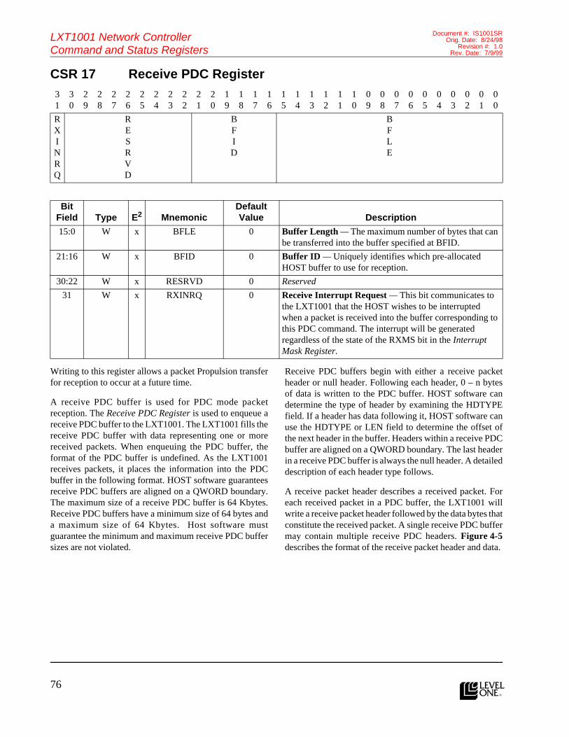
76l
LXT1001 Network ControllerCommand and Status Registers
Document #: IS1001SROrig. Date: 8/24/98
Revision #: 1.0Rev. Date: 7/9/99
Features (cont.)CSR 17 Receive PDC Register
Writing to this register allows a packet Propulsion transferfor reception to occur at a future time.
A receive PDC buffer is used for PDC mode packetreception. The Receive PDC Register is used to enqueue areceive PDC buffer to the LXT1001. The LXT1001 fills thereceive PDC buffer with data representing one or morereceived packets. When enqueuing the PDC buffer, theformat of the PDC buffer is undefined. As the LXT1001receives packets, it places the information into the PDCbuffer in the following format. HOST software guaranteesreceive PDC buffers are aligned on a QWORD boundary.The maximum size of a receive PDC buffer is 64 Kbytes.Receive PDC buffers have a minimum size of 64 bytes anda maximum size of 64 Kbytes. Host software mustguarantee the minimum and maximum receive PDC buffersizes are not violated.
Receive PDC buffers begin with either a receive packetheader or null header. Following each header, 0 – n bytesof data is written to the PDC buffer. HOST software candetermine the type of header by examining the HDTYPEfield. If a header has data following it, HOST software canuse the HDTYPE or LEN field to determine the offset ofthe next header in the buffer. Headers within a receive PDCbuffer are aligned on a QWORD boundary. The last headerin a receive PDC buffer is always the null header. A detaileddescription of each header type follows.
A receive packet header describes a received packet. Foreach received packet in a PDC buffer, the LXT1001 willwrite a receive packet header followed by the data bytes thatconstitute the received packet. A single receive PDC buffermay contain multiple receive PDC headers. Figure 4-5describes the format of the receive packet header and data.
31
30
29
28
27
26
25
24
23
22
21
20
19
18
17
16
15
14
13
12
11
10
09
08
07
06
05
04
03
02
01
00
RXINRQ
RESRVD
BFID
BFLE
Bit Field Type E2 Mnemonic
Default Value Description
15:0 W x BFLE 0 Buffer Length — The maximum number of bytes that can be transferred into the buffer specified at BFID.
21:16 W x BFID 0 Buffer ID — Uniquely identifies which pre-allocated HOST buffer to use for reception.
30:22 W x RESRVD 0 Reserved
31 W x RXINRQ 0 Receive Interrupt Request — This bit communicates to the LXT1001 that the HOST wishes to be interrupted when a packet is received into the buffer corresponding to this PDC command. The interrupt will be generated regardless of the state of the RXMS bit in the Interrupt Mask Register.

77
LXT1001 Network ControllerCommand and Status Registers
Document #: IS1001SROrig. Date: 8/24/98Revision #: 1.0Rev. Date: 7/9/99
l
Figure 4-5: PDC Receive Header and Data Format
The definition of the PDC receive header and data fieldsfollow.
LEN — Length. Indicates the number of bytes in thereceived packet. LEN bytes of received data follow thereceive packet header.
HDTYPE — Header Type. A unique value used to identifythe header type. For a receive packet header, the value is0x1.
PHAD — Physical Address. The PHAD bit indicates thatthe received packet’s destination address matches theLXT1001’s station (MAC) address.
BCAD — Broadcast Address. This bit indicates that thereceived packet’s destination address was the broadcastaddress.
MCAD — Multicast Address. When the LXT1001multicast address filtering mechanism determines that apacket with a multicast destination address should be passedto the HOST, it sets this bit in the PDL header and transfersthe packet to HOST memory.
LGPK — Large Packet. By setting this bit, the LXT1001indicates that the inbound packet was determined to belarger than the maximum allowable length for an ethernetframe. If the LGPKEN enable bit is clear, the LXT1001regards this condition as an error. If the LGPKEN enablebit is set, the LXT1001 does not regard this condition as anerror.
EROV — Overflow Error. For PDCs, buffer overflow canonly occur when the first packet to be deposited in the PDCbuffer is larger than the buffer proper. In this case, theLXT1001 will deliver as much data as will fit into theavailable buffer space and set the EROV bit. Any data thatdoes not fit into the buffer will be discarded. Whenprocessing a PDC that already contains one or more packets,a packet that does not fit into the remaining buffer spacedoes not cause an overflow error. Instead, the PDCcompletes (i.e., it is given to the HOST), and the packet inquestion is delivered into the next available PDC buffer.
ERCR — CRC Error. When the LXT1001 detects that aninbound packet’s CRC does not match the computed value,it sets this bit to signal the condition.
ERRU — Runt Error. If the LXT1001 determines that aninbound packet is shorter than the minimum ethernet packetlength, it sets the ERRU bit.
ERAL — Alignment Error. This bit is set when theLXT1001 receives a packet that is not an integral numberof octets in length.
ERLN — Length Error. This bit is set when the LXT1001detects that an inbound packet’s LLC data is shorter thanthe length specified in the length/type field of the packet’sMAC header.
RXER — Receive Error. Whenever an error condition isdetected for a receive packet, the error bit in that receive
31
30
29
28
27
26
25
24
23
22
21
20
16
15
13
12
11
10
09
08
07
05
04
03
00
RXER
ERAL
ERRU
ERCR
EROV
LGPK
MCAD
BCAD
PHAD
ERLN
RESRVD
HDTYPE
0x01
LEN
RESRVD
UPHDPN
TPHDPN
IPHDPN
UPCKER
TPCKER
IPCKER
RESRVD
VLHT
VLTBIX
RXDATA 3 RXDATA 2 RXDATA 1 RXDATA 0
•••
RXDATA(LEN-1) RXDATA(LEN-2)

78l
LXT1001 Network ControllerCommand and Status Registers
Document #: IS1001SROrig. Date: 8/24/98
Revision #: 1.0Rev. Date: 7/9/99
Features (cont.)packet header is set to 1. This error bit is the “OR” of theERLN, EROV, ERCR, ERRU, and ERAL bits. This bit isalso set if the LGPKEN bit in Mode Register – 1 is clear,the PAERPKEN bit in Mode Register – 1 is set, and theLGPK bit is set.
VLTBIX — VLAN Table Index. This field indicates theindex of the VLAN TCI Table entry that matched the TCIin the received packet’s VLAN tag header. This field onlyhas meaning if the VLHT bit is set.
VLHT — VLAN Hit. When set, this bit indicates thereceived packet contained a VLAN tag header whose TCImatched an entry in the VLAN TCI Table. This bit is set bythe LXT1001 if the VLEN and VLTBEN bits in ModeRegister – 1 are set and the VLAN tag information in thepacket matches an entry in the VLAN TCI Table; otherwisethis bit will not be set.
IPCKER — IP Header Checksum Error. When set, thisbit indicates the packet failed the IP header checksum test.The LXT1001 tests the IP header checksum in packets whenthe RXIPCKEN bit is set in Mode Register – 2 and the packetcontains an IP header. When clear, the packet either passedthe IP header checksum test, did not contain an IP header,or the LXT1001’s checksum support is disabled.
TPCKER — TCP Checksum Error. When set, this bitindicates the packet failed the TCP checksum test. TheLXT1001 tests the TCP checksum in packets when theRXTPCKEN bit is set in Mode Register – 2 and the packetcontains a TCP header and data. When clear, the packeteither passed the TCP checksum test, did not contain a TCPheader, or the LXT1001’s checksum support is disabled.
UPCKER — UDP Checksum Error. When set, this bitindicates the packet failed the UDP checksum test. TheLXT1001 tests the UDP checksum in packets when theRXUPCKEN bit is set in Mode Register – 2 and the packetcontains a UDP header and data. When clear, the packeteither passed the UDP checksum test, did not contain anUDP header, or the LXT1001’s checksum support isdisabled.
IPHDPN — IP Header Present. When set, this bit indicatesthe LXT1001 found an IP header in the packet. When clear,the packet did not contain an IP header. The value of thisbit is valid irrespective of the setting of the RXIPCKEN bitin Mode Register – 2.
TPHDPN — TCP Header Present. When set, this bitindicates the LXT1001 found a TCP header in the packet.When clear, the packet did not contain a TCP header. Thevalue of this bit is valid irrespective of the setting of theRXTPCKEN bit in Mode Register – 2.
UPHDPN — UDP Header Present. When set, this bitindicates the LXT1001 found a UDP header in the packet.When clear, the packet did not contain a UDP header. Thevalue of this bit is valid irrespective of the setting of theRXUPCKEN bit in Mode Register – 2.
RXDATA — Receive Data. Data bytes that constitute thereceived packet.
A null header is used to indicate that no more headers existin a PDC. Figure 4-6 describes the format of the null header.
Figure 4-6: PDC Null Header Format
The definition of the PDC null header field follows.
HDTYPE — Header Type. A unique value used to identifythe header type. For a null header, the value is 0x0.
When an overflow occurs in a PDC buffer, a null header isnot deposited into the PDC buffer, since the overflow
condition implies that the first packet to be delivered wastoo big to fit. In particular, this is true even if the null headeritself is the source of the overflow; e.g., as may occur whena PDC buffer is just large enough to accommodate aninbound packet but not the null header appended by theLXT1001.
31
21
20
16
15
00
RESRVD
HDTYPE
0x00
RESRVD

79
LXT1001 Network ControllerCommand and Status Registers
Document #: IS1001SROrig. Date: 8/24/98Revision #: 1.0Rev. Date: 7/9/99
l
CSR 18 Interrupt Period Register Reserved
CSR 19 TX FIFO Packet Count Register
31
30
29
28
27
26
25
24
23
22
21
20
19
18
17
16
15
14
13
12
11
10
09
08
07
06
05
04
03
02
01
00
TMPE
Bit Field Type E2 Mnemonic
Default Value Description
31:0 RW x TMPE FFFFFFFFh Timer Period — The value in this register specifies the number of clock ticks that elapse before the LXT1001 generates an interrupt if either the DLINRQ or PEINRQ bits are set in the Command Register and the Timer Expired Interrupt Mask bit is set in the Interrupt Mask Register. The clock operates at the speed of the PCI bus (i.e., 33 MHz or 66 MHz).When the DLINRQ bit is set in the Command Register, a single interrupt is generated after the time specified here elapses. If the PEINRQ bit is set in the Command Register, an interrupt is generated each time the count elapses. The PEINRQ bit takes precedence over the DLINRQ bit.
31
30
29
28
27
26
25
24
23
22
21
20
19
18
17
16
15
14
13
12
11
10
09
08
07
06
05
04
03
02
01
00
RESRVD
TXFIPKCN
Bit Field Type E2 Mnemonic
Default Value Description
15:0 R x TXFIPKCN 0 TX FIFO Packet Count — The number of packets in the TX FIFO
31:16 x x RESRVD 0 Reserved
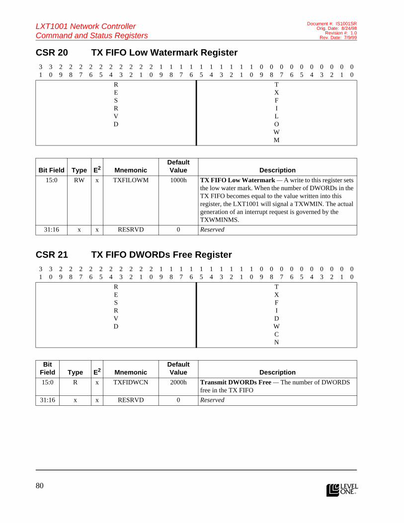
80l
LXT1001 Network ControllerCommand and Status Registers
Document #: IS1001SROrig. Date: 8/24/98
Revision #: 1.0Rev. Date: 7/9/99
Features (cont.)CSR 20 TX FIFO Low Watermark Register
CSR 21 TX FIFO DWORDs Free Register
31
30
29
28
27
26
25
24
23
22
21
20
19
18
17
16
15
14
13
12
11
10
09
08
07
06
05
04
03
02
01
00
RESRVD
TXFILOWM
Bit Field Type E2 MnemonicDefault Value Description
15:0 RW x TXFILOWM 1000h TX FIFO Low Watermark — A write to this register sets the low water mark. When the number of DWORDs in the TX FIFO becomes equal to the value written into this register, the LXT1001 will signal a TXWMIN. The actual generation of an interrupt request is governed by the TXWMINMS.
31:16 x x RESRVD 0 Reserved
31
30
29
28
27
26
25
24
23
22
21
20
19
18
17
16
15
14
13
12
11
10
09
08
07
06
05
04
03
02
01
00
RESRVD
TXFIDWCN
Bit Field Type E2 Mnemonic
Default Value Description
15:0 R x TXFIDWCN 2000h Transmit DWORDs Free — The number of DWORDS free in the TX FIFO
31:16 x x RESRVD 0 Reserved

81
LXT1001 Network ControllerCommand and Status Registers
Document #: IS1001SROrig. Date: 8/24/98Revision #: 1.0Rev. Date: 7/9/99
l
CSR 22 TX FIFO Write Register
When operating in PIO mode, HOST software accesses theTX FIFO directly via this CSR. Data can be written to theCSR using BYTE, WORD, and DWORD accesses.
The first DWORD written to the FIFO contains the numberof bytes in the packet. Subsequent writes to the FIFO containthe packet data itself. Once all packet data has been writtento the FIFO, HOST software initiates the transmission bysetting the SLMDTXCM bit in the Command Register. It is
the HOST software’s responsibility to enforce minimumand maximum packet sizes. The maximum size packet thatcan be written into the TX FIFO is 32 Kbytes (including theTX FIFO packet header). HOST software must not write tothe TX FIFO when it is full.
Figure 4-7 describes the format and sequence of the writesto the TX FIFO.
Figure 4-7: PIO Transmit Header and Data Format
The definitions for the PIO transmit header and data fieldsfollow.
LEN — Length. Indicates the number of bytes to betransmitted. LEN bytes of transmit data follow the transmitpacket header.
VLTBIX — VLAN TCI Table Index. This field is an indexinto the VLAN TCI Table. The LXT1001 uses the TCIinformation at this index to construct a VLAN tag header.
VLIS — VLAN Insert Tag. Setting this bit causes theLXT1001 to construct and insert a VLAN tag header intothe packet prior to its transmission. The LXT1001
31
30
29
28
27
26
25
24
23
22
21
20
19
18
17
16
15
14
13
12
11
10
09
08
07
06
05
04
03
02
01
00
TXFI
WT
TXFI
WT
TXFI
WT
Bit Field Type E2 Mnemonic
Default Value Description
31:0 W x TXFIWT N/A TX FIFO Write — A write to this register will store the value in the TX FIFO. The write can be performed as a BYTE, WORD, or DWORD operation.
31
29
28
27
24
23
16
15
00
RESRVD
VLIS
VLTBIX
RESRVD
LEN
TXDATA 3 – 0
TXDATA 7 – 4
TXDATA 11 – 8
•••
TXDATA(LEN-1)

82l
LXT1001 Network ControllerCommand and Status Registers
Document #: IS1001SROrig. Date: 8/24/98
Revision #: 1.0Rev. Date: 7/9/99
Features (cont.)constructs the VLAN tag header using the TCI at indexVLTBIX in the VLAN TCI Table.
TXDATA — Transmit Data. Data bytes that constitute thepacket to be transmitted.
CSR 23 Reserved
CSR 24 RX FIFO Read Register
When operating in PIO mode, HOST software accesses theRX FIFO directly via the RX FIFO Read Register. Eachread of this CSR retrieves one DWORD of data from theRX FIFO.
The first DWORD read from the FIFO returns the receptionstatus and packet length. The second DWORD read fromthe FIFO returns VLAN tag information. Subsequent reads
to the FIFO return the packet data itself. The maximum sizepacket that can be read from the RX FIFO is 64 Kbytes(including the RX FIFO packet header). NOTE: Droppedpackets will not appear in the FIFO as an errored packet. Ifa packet is dropped, the LXT1001 will simply incrementthe Dropped Packet Count Register.
Figure 4-8 describes the format of a packet in the RX FIFO.
31
30
29
28
27
26
25
24
23
22
21
20
19
18
17
16
15
14
13
12
11
10
09
08
07
06
05
04
03
02
01
00
RESRVD
Bit Field Type E2 Mnemonic
Default Value Description
31:0 x x RESRVD 0 Reserved
31
30
29
28
27
26
25
24
23
22
21
20
19
18
17
16
15
14
13
12
11
10
09
08
07
06
05
04
03
02
01
00
RXFIRD
RXFIRD
RXFIRD
Bit Field Type E2 Mnemonic
Default Value Description
31:0 R x RXFIRD N/A RX FIFO Read — A read from this register will extract the next available value in the RX FIFO. A read when the RX FIFO is empty is undefined and yields invalid data. The read can be performed as a BYTE, WORD, or DWORD operation.

83
LXT1001 Network ControllerCommand and Status Registers
Document #: IS1001SROrig. Date: 8/24/98Revision #: 1.0Rev. Date: 7/9/99
l
Figure 4-8: PIO Receive Header and Data Format
The definitions for the PIO receive header and data fieldsfollow.
LEN — Length. Indicates the number of bytes actuallydeposited into FIFO for the received packet.
PHAD — Physical Address. The PHAD bit indicates thatthe received packet’s destination address matches theLXT1001’s station (MAC) address.
BCAD — Broadcast Address. This bit indicates that thereceived packet’s destination address was the broadcastaddress.
MCAD — Multicast Address. The LXT1001 sets this bit toindicate the received packet met the following conditions:(1) the destination address is a multicast address, and (2) themulticast address hashing algorithm generated a bit thatmatches a bit set in the Multicast Hash Table Register.
LGPK — Large Packet. By setting this bit, the LXT1001indicates that the inbound packet was determined to belarger than the maximum allowable length for an ethernetframe. If the LGPKEN enable bit is clear, the LXT1001regards this condition as an error. If the LGPKEN enablebit is set, the LXT1001 does not regard this condition as anerror.
ERCR — CRC Error. When the LXT1001 detects that aninbound packet’s CRC does not match the computed value,it sets this bit to signal the condition.
ERRU — Runt Error. If the LXT1001 determines that aninbound packet is shorter than the minimum ethernet packetlength, it sets the ERRU bit.
ERAL — Alignment Error. This bit is set when theLXT1001 receives a packet that is not an integral numberof octets in length.
ERLN — Length Error. This bit is set when the LXT1001detects that an inbound packet’s LLC data is shorter thanthe length specified in the length/type field of the packet’sMAC header.
RXER — Receive Error. The LXT1001 sets this bit whenan error condition is detected for a received packet. Thiserror bit is the “OR” of the ERLN, ERCR, ERRU, andERAL bits. This bit is also set if the LGPKEN bit in ModeRegister – 1 is clear, the PAERPKEN bit in Mode Register– 1 is set, and the LGPK bit is set.
VLTBIX — VLAN Table Index. This field indicates theindex of the VLAN TCI Table entry that matched the TCIin the received packet’s VLAN tag header. This field hasmeaning only if the VLHT bit is set.
VLHT — VLAN Hit. When set, this bit indicates thereceived packet contained a VLAN tag header whose TCImatched an entry in the VLAN TCI Table. This bit is set bythe LXT1001 if the VLEN and VLTBEN bits in ModeRegister – 1 are set and the VLAN tag information in the
31
30
29
28
27
26
25
24
23
22
21
16
15
13
12
11
10
09
08
07
05
04
03
00
RXER
ERAL
ERRU
ERCR
RESRVD
LGPK
MCAD
BCAD
PHAD
ERLN
RESRVD
LEN
RESRVD
UPHDPN
TPHDPN
IPHDPN
UPCKER
TPCKER
IPCKER
RESRVD
VLHT
VLTBIX
RXDATA 3-0
RXDATA 7-4
RXDATA 11-9
•••
RXDATA(LEN-1)

84l
LXT1001 Network ControllerCommand and Status Registers
Document #: IS1001SROrig. Date: 8/24/98
Revision #: 1.0Rev. Date: 7/9/99
Features (cont.)packet matches an entry in the VLAN TCI Table; otherwisethis bit will not be set.
IPCKER — IP Header Checksum Error. When set, this bitindicates that the packet failed the IP header checksum test.The LXT1001 tests the IP header checksum in packets whenthe RXIPCKEN bit is set in Mode Register – 2 and thepacket contains an IP header. When clear, the packet eitherpassed the IP header checksum test, did not contain an IPheader, or the LXT1001’s checksum support is disabled.
TPCKER — TCP Checksum Error. When set, this bitindicates that the packet failed the TCP checksum test. TheLXT1001 tests the TCP checksum in packets when theRXTPCKEN bit is set in Mode Register – 2 and the packetcontains a TCP header and data. When clear, the packeteither passed the TCP checksum test, did not contain a TCPheader, or the LXT1001’s checksum support is disabled.
UPCKER — UDP Checksum Error. When set, this bitindicates that the packet failed the UDP checksum test. TheLXT1001 tests the UDP checksum in packets when theRXUPCKEN bit is set in Mode Register – 2 and the packetcontains a UDP header and data. When clear, the packeteither passed the UDP checksum test, did not contain an
UDP header, or the LXT1001’s checksum support isdisabled.
IPHDPN — IP Header Present. When set, this bit indicatesthat the LXT1001 found an IP header in the packet. Whenclear, the packet did not contain an IP header. The value ofthis bit is valid irrespective of the setting of the RXIPCKENbit in Mode Register – 2.
TPHDPN — TCP Header Present. When set, this bitindicates that the LXT1001 found a TCP header in thepacket. When clear, the packet did not contain a TCP header.The value of this bit is valid irrespective of the setting ofthe RXTPCKEN bit in Mode Register – 2.
UPHDPN — UDP Header Present. When set, this bitindicates that the LXT1001 found an UDP header in thepacket. When clear, the packet did not contain an UDPheader. The value of this bit is valid irrespective of thesetting of the RXUPCKEN bit in Mode Register – 2.
RXDATA — Received Data. Data bytes that constitute thereceived packet. If the RXDATA does not end on aQWORD boundary, HOST software will issue a RX FIFOskip packet command to the LXT1001. Alternatively,HOST software can also perform one more read of the RXFIFO and discard the data.
CSR 25 Reserved31
30
29
28
27
26
25
24
23
22
21
20
19
18
17
16
15
14
13
12
11
10
09
08
07
06
05
04
03
02
01
00
RESRVD
Bit Field Type E2 Mnemonic
Default Value Description
31:0 x x RESRVD 0 Reserved

85
LXT1001 Network ControllerCommand and Status Registers
Document #: IS1001SROrig. Date: 8/24/98Revision #: 1.0Rev. Date: 7/9/99
l
CSR 26 RX FIFO DWORD Count Register
CSR 27 RX FIFO High Watermark Register
31
30
29
28
27
26
25
24
23
22
21
20
19
18
17
16
15
14
13
12
11
10
09
08
07
06
05
04
03
02
01
00
RESRVD
RXFIDWCN
Bit Field Type E2 Mnemonic
Default Value Description
15:0 R x RXFIDWCN 0 RX FIFO DWORD Count — The number of DWORDS currently consumed by received packets in the RX FIFO.
31:16 x x RESRVD x Reserved
31
30
29
28
27
26
25
24
23
22
21
20
19
18
17
16
15
14
13
12
11
10
09
08
07
06
05
04
03
02
01
00
RESRVD
RXFIHI
WM
Bit Field Type E2 Mnemonic
Default Value Description
15:0 RW x RXFIHIWM 2000h RX FIFO High Watermark — A write to this register sets the high water mark for the RX FIFO. When the number of DWORDs in the RX FIFO becomes equal to the value written into this register, the LXT1001 will signal a RXWMIN. The actual generation of an interrupt request is governed by the RXWMINMS.
31:16 x x RESRVD x Reserved

86l
LXT1001 Network ControllerCommand and Status Registers
Document #: IS1001SROrig. Date: 8/24/98
Revision #: 1.0Rev. Date: 7/9/99
Features (cont.)CSR 28 RX FIFO Packet Count Register
CSR 29 Command Register
31
30
29
28
27
26
25
24
23
22
21
20
19
18
17
16
15
14
13
12
11
10
09
08
07
06
05
04
03
02
01
00
RESRVD
RXFIPKCN
Bit Field Type E2 Mnemonic
Default Value Description
15:0 R x RXFIPKCN 0 RX FIFO Packet Count — The number of packets in the RX FIFO
31:16 x x RESRVD x Reserved
31
30
29
28
27
26
25
24
23
22
21
20
19
18
17
16
15
14
13
12
11
10
09
08
07
06
05
04
03
02
01
00
RESRVD
RESRVD
RESRVD
RESRVD
TMEN1
TMEN0
PEINRQ
DLINRQ
RXFISKPK
SLMDTXCM
SERECL
Bit Field Type E2 Mnemonic
Default Value Description
0 W x SERECL N/A Set/Reset Control — Set/reset control bit for bits[7:1].
1 WA x SLMDTXCM 0 Slave Mode Transmit Command — HOST software sets this bit to initiate the transmission of a packet it has placed in the TX FIFO. Prior to setting this bit, HOST software must write all the packet’s PIO transmit header and packet data to the FIFO using the TX FIFO Write Register.
2 WA x RXFISKPK 0 RX FIFO Skip Packet — Setting this bit causes the current packet in the RX FIFO to be discarded. The LXT1001 advances the RX FIFO’s current packet pointer to the next available packet and decrements the RXFIPKCN Register.

87
LXT1001 Network ControllerCommand and Status Registers
Document #: IS1001SROrig. Date: 8/24/98Revision #: 1.0Rev. Date: 7/9/99
l
3 WA x DLINRQ 0 Delayed Interrupt Request — Setting this bit causes the LXT1001 to start a countdown timer. Upon expiration of the timer, the LXT1001 clears the DLINRQ bit and generates an interrupt if the TMEXMS bit in the Interrupt Mask Register is set. The initial value of the countdown timer is determined by the value in the Interrupt Period Register.If HOST software resets the DLINRQ bit before the countdown timer expires, the LXT1001 will cancel the timer and no interrupt occurs.
4 RW x PEINRQ 0 Periodic Interrupt Request — Setting this bit causes the LXT1001 to start a countdown timer. The duration of the timer is the value specified in the Interrupt Period Register. Upon expiration of the timer, the LXT1001 performs the following actions:
• Checks the state of the TMEXMS bits in the Interrupt Mask Register. If the TMEXMS bit is set, the LXT1001 generates an interrupt.
• Checks the state of the PEINRQ bit. If it is still set, the LXT1001 reloads the timer with the value in the Interrupt Mask Register and restarts the timer.
The LXT1001 continues in this cycle until the HOST software resets the PEINRQ bit.If the HOST software resets the PEINRQ bit before the countdown timer expires, the LXT1001 cancels the timer and no more periodic timer interrupts occur.
5 RW x TMEN0 0 Timer 0 Enable — Setting this bit starts Timer 0 ticking. The timer ticks at a rate of 25 MHz. Each tick causes the value in the Timer 0 Count Register to be incremented.Clearing this bit causes the timer to stop ticking and, therefore, the value in the Timer 0 Count Register to stop incrementing.
6 RW x TMEN1 0 Timer 1 Enable — Setting this bit starts Timer 1 ticking. The timer ticks at a rate of 25 MHz. Each tick causes the value in the Timer 1 Count Register to be incremented.Clearing this bit causes the timer to stop ticking and, therefore, the value in the Timer 1 Count Register to stop incrementing.
7 x x RESRVD 0 Reserved
15:8 x x RESRVD 0 Reserved
31:16 x x RESRVD 0 Reserved
Bit Field Type E2 Mnemonic
Default Value Description

88l
LXT1001 Network ControllerCommand and Status Registers
Document #: IS1001SROrig. Date: 8/24/98
Revision #: 1.0Rev. Date: 7/9/99
Features (cont.)CSR 30 Interrupt Mask Register
31
30
29
28
27
26
25
24
23
22
21
20
19
18
17
16
15
14
13
12
11
10
09
08
07
06
05
04
03
02
01
00
RESRVD
RESRVD
TMMS1
TMMS0
USPI
MS1
USPI
MS0
SERECL
RESRVD
RXMGPKMS
PHLASTMS
RXPDMS
RXMS
RXFI
WMMS
RXCMEMMS
SERECL
INENMS
TMEXMS
RESRVD
TXDMDNMS
TXFI
WMMS
TXCMEMMS
SERECL
Bit Field Type E2 Mnemonic
Default Value Description
0 W x SERECL N/A Set/Reset Control — Set/reset control bit for bits[7:1]
1 RW x TXCMEMMS 0 TX Command FIFO Empty Interrupt Mask
2 RW x TXFIWMMS 0 TX FIFO Watermark Interrupt Mask
3 RW x TXDMDNMS 0 Transmit DMA Done Interrupt Mask
5:4 x x RESRVD 0 Reserved
6 RW x TMEXMS 0 Timer Expired Interrupt Mask — When set, an interrupt will occur when the single shot or periodic timer has expired. This timer is started when the setting of either the DLINRQ or PEINRQ bits in the Command Register has expired. The duration of the timer is the determined by the value specified in the Interrupt Period Register.
7 RW x INENMS 0 Interrupt Enable Mask—This bit is the master interrupt enable bit that enables/disables the LXT1001’s ability to generate an interrupt. When set, the LXT1001 will generate an interrupt whenever an event bit (bits 23:0) in the Event Status Register is set and the event bit’s corresponding mask bit is set in this register. For example, if the INENMS bit is set (bit 6 is set in the Event Status Register and in the Interrupt Mask Register), the LXT1001 generates an interrupt.When the INENMS bit is clear, the LXT1001’s ability to generate an interrupt is disabled. NOTE: Clearing the INENMS bit does NOT prevent the LXT1001 from setting event bits [23:0] in the Event Status Register. Clearing the INENMS bit merely prevents the LXT1001 from interrupting the HOST. If any of the Event Status Register bits [23:0] are set and the event bit’s corresponding mask bit is set when HOST software sets INENMS bit, the LXT1001 will interrupt the HOST immediately.
8 W x SERECL 0 Set/Reset Control — Set/reset control bit for bits [15:9]
9 RW x RXCMEMMS 0 RX Command FIFO Empty Interrupt Mask
10 RW x RXFIWMMS 0 RX FIFO Watermark Interrupt Mask

89
LXT1001 Network ControllerCommand and Status Registers
Document #: IS1001SROrig. Date: 8/24/98Revision #: 1.0Rev. Date: 7/9/99
l
This register controls the LXT1001’s ability to generateinterrupts.
11 RW x RXMS 0 Receive Interrupt Mask — This bit enables the LXT1001 to generate interrupts whenever the LXT1001 has placed a complete packet into the RX FIFO.
12 RW x RXPDMS 0 Receive PDL/PDC Interrupt Mask — When set, this bit enables per PDC/PDL interrupts as requested in the flags field of the PDC/PDL descriptors or commands. The interrupts are generated when the LXT1001 has completely transferred the packet data to HOST buffers.
13 RW x PHLASTMS 0 Physical Layer Status Interrupt Mask — When set, the LXT1001 generates an interrupt when a PHY status change occurs.
14 RW x RXMGPKMS 0 Receive Magic Packet Mask — When set, reception of a Magic Packet data sequence will generate an interrupt.
15 x x RESRVD 0 Reserved
16 W x SERECL 0 Set/Reset Control — Set/reset control bit for bits [23:17]
17 RW x USPIMS0 0 User Pin0 Interrupt Mask — This bit enables/disables the generation of an interrupt based upon the state of User Pin0. If this bit is set, and the User Pin0 transitions from a low to high state, the LXT1001 generates an interrupt.
18 RW x USPIMS1 0 User Pin1 Interrupt Mask — This bit enables/disables the generation of an interrupt based upon the state of User Pin1. If this bit is set, and the User Pin1 transitions from a low to high state, the LXT1001 generates an interrupt.
19 RW x TMMS0 0 Timer 0 Interrupt Mask — This bit enables/disables the generation of an interrupt when the value of the Timer 0 Counter Register equals the value of the Timer 0 Interrupt Trigger Register.
20 RW x TMMS1 0 Timer 1 Interrupt Mask — This bit enables/disables the generation of an interrupt when the value of the Timer 1 Counter Register equals the value of the Timer 1 Interrupt Trigger Register.
31:21 x x RESRVD 0 Reserved
Bit Field Type E2 Mnemonic
Default Value Description

90l
LXT1001 Network ControllerCommand and Status Registers
Document #: IS1001SROrig. Date: 8/24/98
Revision #: 1.0Rev. Date: 7/9/99
Features (cont.)CSR 31 Reserved
CSR 32 Event Status Register
31
30
29
28
27
26
25
24
23
22
21
20
19
18
17
16
15
14
13
12
11
10
09
08
07
06
05
04
03
02
01
00
RESRVD
Bit Field Type E2 Mnemonic
Default Value Description
31:0 x x RESRVD 0 Reserved
31
30
29
28
27
26
25
24
23
22
21
20
19
18
17
16
15
14
13
12
11
10
09
08
07
06
05
04
03
02
01
00
RXDMDNCN
RESRVD
TMIN1
TMIN0
USPIIN1
USPIIN0
RESRVD
RESRVD
RXMGPKIN
PHLASTIN
RXPDIN
RXIN
RXFI
WMIN
RXCMEMIN
RESRVD
RESRVD
TMEXIN
RESRVD
TXDMDNIN
TXFI
WMIN
TXCMEMIN
RESRVD
Bit Field Type E2 Mnemonic
Default Value Description
0 x x RESRVD N/A Reserved
1 RC x TXCMEMIN 0 Transmit Command FIFO Empty Interrupt — This interrupt signals that the transmit command FIFO is empty. This bit is set when the transmit command count rises above 0 and then returns to 0.
2 RC x TXFIWMIN 0 TX FIFO Watermark Interrupt — This interrupt is asserted when the number of DWORDS in the TX FIFO becomes equal to the number of DWORDS specified in the TXFIWM Register due to a read by the MAC.
3 RC x TXDMDNIN 0 Transmit DMA Done Interrupt — When set, this bit indicates that the LXT1001 has transferred a packet with the DMDINRQ flag set in the PDL or PDC command field. If multiple packets have been transferred, as can happen with a PDC, the interrupt is signaled after the final packet has been copied to the LXT1001.

91
LXT1001 Network ControllerCommand and Status Registers
Document #: IS1001SROrig. Date: 8/24/98Revision #: 1.0Rev. Date: 7/9/99
l
5:4 RC x RESRVD 0 Reserved
6 RC x TMEXIN 0 Timer Expired Interrupt
7 RC x RESRVD 0 Reserved
8 RC x RESRVD 0 Reserved
9 RC x RXCMEMIN 0 Receive Command FIFO Empty Interrupt — This interrupt signals that the receive command FIFO is empty. The LXT1001 asserts this signal immediately after the last receive PDC/PDL is extracted from the receive command FIFO. This bit is set when the receive command count rises above 0 and then returns to 0.
10 RC x RXFIWMIN 0 RX FIFO Watermark Interrupt — This interrupt is asserted when the number of DWORDS in the RX FIFO becomes equal to the number of DWORDS specified in the RXFIWM Register due to a write by the MAC.
11 RC x RXIN 0 Receive Interrupt — The LXT1001 generates receive interrupts whenever a complete packet is available in the RX FIFO. Note that RXIN interrupts override RXPDIN interrupts. In other words, when the RXMS bit is set, an RXIN interrupt is generated for each packet that is received by the LXT1001 irrespective of how the RXINRQ bit is set in the receive PDCs and PDLs.
12 RC x RXPDIN 0 Receive PDC/PDL Interrupt — When the Interrupt Mask Register RXPDMS bit is set to 1, the LXT1001 generates receive interrupts for each packet received into a PDC or PDL style buffer that has the RXINRQ bit set. The RXPDIN interrupt is asserted only after the LXT1001 has transferred the complete packet (or group of packets in PDC mode) to HOST memory.Note that if RXIN interrupts are also enabled (InterruptMaskRegister.RXMS=1), then each received packet generates an interrupt (InterruptStatusRegister.RXIN=1) irrespective of the state of the RXINRQ bit in receive PDCs or PDLs.
13 x x PHLASTIN 0 Physical Layer Status Interrupt — When set, this bit indicates the LXT1001 has detected a PHY status change. HOST software can obtain the current PHY status via the G/MII PHY Access Register.
14 RC x RXMGPKIN 0 Receive Magic Packet Interrupt — When set, this bit indicates that a Magic Packet data sequence was received.
15 RC x RESRVD 0 Reserved
16 RC x RESRVD 0 Reserved
17 RC x USPIIN0 0 User Pin0 Interrupt — An interrupt occurs when the User Pin0 transitions from a low to high state.
18 RC x USPIIN1 0 User Pin1 Interrupt — An interrupt occurs when the User Pin1 transitions from a low to high state.
Bit Field Type E2 Mnemonic
Default Value Description

92l
LXT1001 Network ControllerCommand and Status Registers
Document #: IS1001SROrig. Date: 8/24/98
Revision #: 1.0Rev. Date: 7/9/99
Features (cont.)
The Event Status Register indicates the events that havebeen detected by the device. When an event is detected, thecorresponding bit in this register is set. If both the INENMSbit and the event’s corresponding mask bit are set in theInterrupt Mask Register, then the occurrence of the eventcauses the device to signal an interrupt. Following a read ofany of the event status bits in this register, the LXT1001automatically resets all the event status bits. Moreover, theLXT1001 automatically resets the INENMS bit in theInterrupt Mask Register if an interrupt is pending (i.e., the
LXT1001’s interrupt line is active). This automatic clearingof the INENMS bit disables the LXT1001’s ability togenerate further interrupts. To re-enable LXT1001interrupts, the HOST software must set the INENMS bit inthe Interrupt Mask Register. When the HOST software setsthe INENMS bit, the LXT1001 will immediately signal aninterrupt for any pending events; i.e., events havingoccurred after the last read of the Event Status Register.
19 RC x TMIN0 0 Timer 0 Interrupt — An interrupt occurs when the value of the Timer 0 Count Register equals the value of the Timer 0 Interrupt Trigger Register.
20 RC x TMIN1 0 Timer 1 Interrupt — An interrupt occurs when the value of the Timer 1 Count Register equals the value of the Timer 1 Interrupt Trigger Register.
23:21 RC x RESRVD 0 Reserved
31:24 RC x RXDMDNCN 0 Receive DMA Done Count — The count of receive PDL/PDCs that the LXT1001 has completed processing since the last read of this field. The receive command queue can hold 31 commands. HOST software uses this field to determine how many receive PDL/PDC buffers have been filled with receive data by the LXT1001. The LXT1001 resets the count to zero after each read.NOTE: This field can be accessed as a BYTE, WORD, or DWORD. A BYTE read of this field has no affect on the state of other fields in the CSR. A BYTE read of this field does NOT disable the LXT1001’s ability to generate interrupts.NOTE: This field is aliased from the Command Status Register. Whether the count is read via the Command Status Register or the Event Status Register, the LXT1001 will reset the count after the read.
Bit Field Type E2 Mnemonic
Default Value Description

93
LXT1001 Network ControllerCommand and Status Registers
Document #: IS1001SROrig. Date: 8/24/98Revision #: 1.0Rev. Date: 7/9/99
l
CSR 33 Reserved
CSR 34 Multicast Hash Table Register LSD
When enabling a multicast address, the driver computes thehash value and makes the LXT1001 aware of the new
address by writing a new hash value into MCHSTBLO orMCHSTBHI.
31
30
29
28
27
26
25
24
23
22
21
20
19
18
17
16
15
14
13
12
11
10
09
08
07
06
05
04
03
02
01
00
RESRVD
Bit Field Type E2 Mnemonic
Default Value Description
31:0 x x RESRVD 0 Reserved
31
30
29
28
27
26
25
24
23
22
21
20
19
18
17
16
15
14
13
12
11
10
09
08
07
06
05
04
03
02
01
00
MCHSTBLO
Bit Field Type E2 Mnemonic
Default Value Description
31:0 W x MCHSTBLO 0 Multicast Hash Table Low — The Multicast Hash Table is set by the driver to indicate to the LXT1001 which multicast addresses are acceptable to the HOST. The hashing algorithm is an imperfect filter. Consequently, the HOST must ultimately examine inbound packets with multicast destination addresses to determine if they are indeed intended for the recipient HOST. The Multicast Address Table is 64 bits wide. Bits 31 through 0 of the table are maintained in this register.

94l
LXT1001 Network ControllerCommand and Status Registers
Document #: IS1001SROrig. Date: 8/24/98
Revision #: 1.0Rev. Date: 7/9/99
Features (cont.)CSR 35 Multicast Hash Table Register MSD
When enabling a multicast address, the driver computes thehash value and makes the LXT1001 aware of the new
address by writing a new hash value into MCHSTBLO orMCHSTBHI.
CSR 36 LED 0 Configuration Register
31
00
MCHSTBHI
Bit Field Type E2 Mnemonic
Default Value Description
31:0 W x MCHSTBHI 0 Multicast Hash Table High — Bits 63 through 32 of the table are maintained in this register.
31
30
29
28
27
26
25
24
23
22
21
20
19
18
17
16
15
14
13
12
11
10
09
08
07
06
05
04
03
02
01
00
LDOU
RESRVD
RESRVD
CA
CO
JA
RX
TX
ADMA
LKST
AN
FD
RESRVD
1000MB
100MB
10MB
PUXP
LDIPSGPL
LDEN
RESRVD
Bit Field Type E2 Mnemonic
Default Value Description
0 x x RESRVD 0 Reserved
1 RW √ LDEN 1 LED Enable — Allows the LED to be turned off without upsetting the programming of the LED Configuration Register. This bit permits the LED configuration to be taken directly from EEPROM without driver intervention. The driver need only enable the LED if it is disabled.
2 RW √ LDIPSGPL 1 LED Input Signal Polarity — Inverts the input signal to the LED.
3 RW √ PUXP 1 Pulse Expander — Stretches the time that the LED is on (or off) such that it can be easily perceived visually.

95
LXT1001 Network ControllerCommand and Status Registers
Document #: IS1001SROrig. Date: 8/24/98Revision #: 1.0Rev. Date: 7/9/99
l
CSR 37 LED 1 Configuration RegisterSee LED 0 Configuration Register for a detailed descriptionof the programming.
4 RW √ 10MB 0 10 Megabit — Indicates that the LXT1001 is configured for 10 Mb operation. When this bit is set and the 10MB bit in the LED Signal Latch Register is set, the signal sent to the LED will oscillate at 1 Hz.
5 RW √ 100MB 0 100 Megabit — Indicates that the LXT1001 is configured for 100 Mb operation. When this bit is set and the 100MB bit in the LED Signal Latch Register is set, the signal sent to the LED will oscillate at 4 Hz.
6 RW √ 1000MB 0 1000 Megabit — Indicates that the LXT1001 is configured for 1000 Mb operation.
7 x x RESRVD 0 Reserved
8 RW √ FD 0 Full-Duplex — Indicates that full-duplex operation is enabled.
9 RW √ AN 0 Auto Negotiating — Indicates that auto negotiation is in progress.
10 RW √ LKST 1 Link State — Indicates whether the link is functional or nonfunctional.
11 RW √ ADMA 0 Address Match — Indicates that an address match with the LXT1001’s physical address has been detected.
12 RW √ TX 0 Transmit — Indicates that the LXT1001 is transmitting a frame.
13 RW √ RX 0 Receive — Indicates that the LXT1001 is receiving a frame.
14 RW √ JA 0 Jabber — Indicates that the LXT1001 has detected a jabbering station.
15 RW √ CO 0 Collision — This bit indicates that the LXT1001 is transmitting and receiving data simultaneously. In half-duplex mode, transmitting and receiving data simultaneously is an error condition known as a collision. In full-duplex mode, transmitting and receiving data simultaneously is not an error condition. This bit should not be set when operating in full-duplex mode.
16 RW √ CA 0 Carrier Sense — Indicates PHY has sensed a CARRIER.
30:17 x x RESRVD 0 Reserved
31 R x LDOU x LED Out — The signal sent to the LED is routed to this bit as well.
Bit Field Type E2 Mnemonic
Default Value Description

96l
LXT1001 Network ControllerCommand and Status Registers
Document #: IS1001SROrig. Date: 8/24/98
Revision #: 1.0Rev. Date: 7/9/99
Features (cont.)CSR 38 LED 2 Configuration RegisterSee LED 0 Configuration Register for a detailed descriptionof the programming.
CSR 39 LED 3 Configuration RegisterSee LED 0 Configuration Register for a detailed descriptionof the programming.
CSR 40 Reserved31
30
29
28
27
26
25
24
23
22
21
20
19
18
17
16
15
14
13
12
11
10
09
08
07
06
05
04
03
02
01
00
RESRVD
Bit Field Type E2 Mnemonic
Default Value Description
31:0 R x RESRVD 0 Reserved

97
LXT1001 Network ControllerCommand and Status Registers
Document #: IS1001SROrig. Date: 8/24/98Revision #: 1.0Rev. Date: 7/9/99
l
CSR 41 EEPROM Data Register
CSR 42 LAN Physical Address Register LSD
The LAN physical address registers are programmed withthe MAC address of the LXT1001. The LXT1001 willaccept all frames that have a destination MAC address
(OUI) matching the one programmed into this CSR whenthe unicast enable (UCEN) bit is set in Mode Register – 1(CSR 0). When UCEN is reset, the LXT1001 will not accept
31
30
29
28
27
26
25
24
23
22
21
20
19
18
17
16
15
14
13
12
11
10
09
08
07
06
05
04
03
02
01
00
EEDA
Bit Field Type E2 Mnemonic
Default Value Description
31:0 RW x EEDA 0 EEPROM Data Register — This is the data register used when performing single accesses to EEPROM. When reading from EEPROM, the LXT1001 places value read from EEPROM in this register. HOST software must not read this register until after the LXT1001 has cleared the EESI bit.When writing to EEPROM, this register contains the value to be written. HOST software must set the value in this register prior to setting the EESI bit. HOST software must not change this value until after the LXT1001 has cleared the EESI bit.
31
30
29
28
27
26
25
24
23
22
21
20
19
18
17
16
15
14
13
12
11
10
09
08
07
06
05
04
03
02
01
00
PHAD3
PHAD2
PHAD1
PHAD0
Bit Field Type E2 Mnemonic
Default Value Description
31:0 RW √ PHAD0-3 0083E000h Physical Address 0–3 — When programming the LXT1001’S MAC address, bytes 0 through 3 of the 6-byte address are written to this register. For purposes of this discussion, byte 0 is the first byte of the OUI as transmitted on the physical medium. The example below further clarifies the point. The LXT1001 uses the DWORD programmed into this register along with the WORD programmed into CSR 43 to select unicast frames specifically directed at the LXT1001.

98l
LXT1001 Network ControllerCommand and Status Registers
Document #: IS1001SROrig. Date: 8/24/98
Revision #: 1.0Rev. Date: 7/9/99
Features (cont.)any unicast frames unless the promiscuous mode enable(POEN) bit is set, in which case all frames are accepted.
Level One Technologies’ OUI is: 00-E0-83. A sample MACaddress based on this OUI is:
00-E0-83-01-02-03
The notation above is frequently referred to as canonicalformat. In canonical format, the leftmost hexadecimal value(00 in the example) is transmitted first. The hexadecimalvalue immediately to its right (E0 in the example) is
transmitted next, and so on. Each hexadecimal valuerepresents a byte where bit 0 has the value 20, bit 1 has thevalue 21, etc., through bit 7. For purposes of this example,the leftmost byte is referred to as byte 0 (PHAD0 in the CSRdiagram above) and the rightmost byte is referred to as byte5.
When bytes 0 through 3 of the physical address are writtento this register (CSR 42), byte 0 is written to bits 0 through7, byte 1 is written to bits 8 through 15, etc. The result is asfollows:
The remaining 2 bytes of the MAC address are depositedinto the LAN Physical Address Register MSW (CSR 43) asfollows:
CSR 43 LAN Physical Address Register MSW
31
30
29
28
27
26
25
24
23
22
21
20
19
18
17
16
15
14
13
12
11
10
09
08
07
06
05
04
03
02
01
00
01 83 E0 00
31
30
29
28
27
26
25
24
23
22
21
20
19
18
17
16
15
14
13
12
11
10
09
08
07
06
05
04
03
02
01
00
Reserved Reserved 03 02
31
30
29
28
27
26
25
24
23
22
21
20
19
18
17
16
15
14
13
12
11
10
09
08
07
06
05
04
03
02
01
00
RESRVD
PHAD5
PHAD4
Bit Field Type E2 Mnemonic
Default Value Description
15:0 RW √ PHAD 4–5 0100h Physical Address 4–5 — The LXT1001’s MAC address, bytes 4 and 5. The most significant WORD of the OUI is programmed in this register.
31:16 RW x RESRVD x Reserved

99
LXT1001 Network ControllerCommand and Status Registers
Document #: IS1001SROrig. Date: 8/24/98Revision #: 1.0Rev. Date: 7/9/99
l
CSR 44 G/MII PHY Access Register
HOST software uses the G/MII PHY Access Register toaccess the PHY’s status and control registers. Prior toforcing the PHY to renegotiate with its link partner, it is the
responsibility of HOST software to quiesce packettransmission and reception by clearing the Transmit Enableand Receive Enable bits in Mode Register – 1.
31
30
29
28
27
26
25
24
23
22
21
20
19
18
17
16
15
14
13
12
11
10
09
08
07
06
05
04
03
02
01
00
GMDA
GMST
RESRVD
GMPHAD
GMCM
RESRVD
GMRRIX
Bit Field Type E2 Mnemonic
Default Value Description
4:0 RW x GMRRIX 0 G/MII Register Index — Index of the PHY register to be targeted by the I/O operation.
6:5 x x RESRVD 0 Reserved
7 RW x GMCM 0 G/MII Command — If GMCM = 0, a read of the PHY register specified by GMRRIX is performed. The result is stored in the GMDA.If GMCM = 1, a write of the value in the GMDA is written to the PHY register specified by GMRRIX.
12:8 RW x GMPHAD 0 G/MII Physical Address — Physical address of the PHY device to which I/O is to be performed.
14:13 x x RESRVD 0 Reserved
15 RA x GMST 0 G/MII Command Status — HOST software polls this bit to determine when a command to the PHY has completed. The LXT1001 sets this bit when a write to the G/MII PHY Access Register occurs. The LXT1001 will clear this bit when it has completed the I/O operation with the PHY.
31:16 RW x GMDA 0 G/MII Data — If GMCM = 0, GMDA contains the value read from the PHY. The value will be valid after the GMST bit indicates the read operation has completed.If GMCM = 1, GMDA contains the value to be written to the PHY. GMDA must not be altered by HOST software until the GMST bit indicates the write operation has completed.

100l
LXT1001 Network ControllerCommand and Status Registers
Document #: IS1001SROrig. Date: 8/24/98
Revision #: 1.0Rev. Date: 7/9/99
Features (cont.)CSR 45 G/MII Mode Register
31
30
29
28
27
26
25
24
23
22
21
20
19
18
17
16
15
14
13
12
11
10
09
08
07
06
05
04
03
02
01
00
RESRVD
GMPCEN
GMIFPR
RESRVD
GMFD
GMWRSP
Bit Field Type E2 Mnemonic
Default Value Description
1:0 RW x GMWRSP 10 G/MII Wire Speed — HOST software writes these bits to select between the following wire speeds:
GMWRSP[1] GMWRSP[0] Line Rate1 1 Reserved1 0 1000 Mbps0 1 100 Mbps0 0 10 Mbps
HOST software sets this field to match the wire speed at which the PHY is currently operating. HOST software determines the current PHY setting using the G/MII PHY Access Register.
2 RW x GMFD 1 G/MII Full-Duplex Mode — HOST software writes this bit to select between full-duplex mode and half-duplex mode. If GMFD = 1, then full-duplex mode is selected. If GMFD = 0, then half-duplex mode is selected.HOST software sets this field to match the wire speed at which the PHY is currently operating. HOST software determines the current PHY setting using the G/MII PHY Access Register.
7:3 RW x RESRVD 0 Reserved
8 RW x GMIFPR x G/MII Interface Protocol — This bit selects the interface protocol to use (TBI or G/MII). If GMIFPR is set to logic 1, then the TBI interface protocol is used to connect to a SERDES PHY device. If GMIFPR is cleared to logic 0, then the G/MII interface protocol is used to connect to a G/MII PHY device. Upon reset, this bit is set to the value on the PCS_EN pin.
9 R x GMPCEN x G/MII PCS Enhance — This bit indicates whether the external PHY device needs to be enhanced by the internal PCS. If GMPCEN is read as logic 1, then the external PHY requires the internal PCS. If GMPCEN is read as logic 0, then the external PHY does not require the internal PCS.
31:10 RW x RESRVD 0 Reserved

101
LXT1001 Network ControllerCommand and Status Registers
Document #: IS1001SROrig. Date: 8/24/98Revision #: 1.0Rev. Date: 7/9/99
l
CSR 46 Statistic Index Register
This register is used in conjunction with the Statistic ValueRegister to read statistics maintained by the LXT1001. Toread the values of a particular statistic, HOST softwareselects the statistic by writing the statistic index to thisregister. The act of selecting the index causes the LXT1001to take two actions: first, the current value of the statistic islatched into the Statistic Value Register, and second, the
statistic is reset to 0. HOST software then reads the latchedvalue of the selected statistic from the Statistic ValueRegister.
The table below defines the statistics kept by the LXT1001..
31
30
29
28
27
26
25
24
23
22
21
20
19
18
17
16
15
14
13
12
11
10
09
08
07
06
05
04
03
02
01
00
RESRVD
RESRVD
RESRVD
RESRVD
SCIX
Bit Field Type E2 Mnemonic
Default Value Description
4:0 W x SCIX 0 Statistic Index — The index of the statistic whose value is to be placed into the Statistic Value Register. See Table 4-1 for a description of each statistic kept by the LXT1001.
31:5 x x RESRVD 0 Reserved
SCIX Statistic Name Description0 aFramesTransmittedOK Count of frames transmitted successfully by the LXT1001. Frames that
encounter single or multiple collisions are included in this count. Frames that encounter the maximum number of collisions are not included. The count does not wrap.
1 aSingleCollisionFrames Count of frames that experienced single collision prior to successful transmission. The count does not include frames that encountered a late collision, multiple collisions, or the maximum number of collisions. The count does not wrap.
2 aMultipleCollisionFrames Count of frames that experienced multiple collisions prior to successful transmission. The count does not include frames that encountered a late collision, a single collision, or the maximum number of collisions. The count does not wrap.
3 aFramesReceivedOK Count of frames received without error and passed the LXT1001’s destination address filter. If the VLAN support is enabled, the packet must also pass the VLAN filter. The count does not wrap.
4 aFrameCheckSequenceErrors Count of frames received with FCS errors. This count does not include frames that had alignment errors. The count does not wrap.
5 aAlignmentErrors A count of frames received with alignment errors. An alignment error occurs when the received frame is not an integral number of octets in length and does not pass the FCS check. The count does not wrap.

102l
LXT1001 Network ControllerCommand and Status Registers
Document #: IS1001SROrig. Date: 8/24/98
Revision #: 1.0Rev. Date: 7/9/99
Features (cont.)6 Dropped Packet Count The number of dropped packets. A packet is considered dropped if it
passed the LXT1001’s destination address filter and VLAN filter, but could not be successfully received due to an internal error or lack of resource in the LXT1001. The count does not wrap.
7 Errored Receive Packet Count The number of packets that encountered an error during packet reception. This register is the sum of all errors detected by the LXT1001 during packet reception. The count does not wrap.
8 Errored Transmit Packet Count The number of packets that encountered an error during transmission. This register is the sum of all errors detected by the LXT1001 during packet transmission. This count does not include packets that encountered single or multiple collisions. The count does not wrap.
9 Late Collision Count A count of frames that encountered a late collision during transmission. A late collision is defined as a collision that occurs after at least minimum frame size bytes of a frame has been transmitted. The count does not wrap.
10 Runt Packet Count A count of frames received that were smaller than the minimum frame size of 64 bytes (including CRC). The count does not wrap.
11 aFrameTooLong A count of frames received that were larger than the maximum packet size. The count does not wrap.
12 VLAN Accepted Packet Count A count of VLAN tagged frames received that were accepted by the LXT1001. The count does not wrap.
13 VLAN Discarded Packet Count A count of VLAN tagged frames received that were discarded by the LXT1001. The LXT1001 discards VLAN tagged frames if the VLEN and VLTBEN bits are set in Mode Register – 1 and the VLAN tag in the frame does not match any entries in the VLAN TCI Table. The count does not wrap.
14 TCP/IP IP Checksum Error Count A count of TCP/IP packets that contained an IP header and failed the LXT1001’s IP checksum test. This count is incremented regardless of the state of the PACKEREN bit in Mode Register – 2. The count does not wrap.
15 TCP/IP UDP Checksum Error Count
A count of TCP/IP packets that contained a UDP header and failed the LXT1001’s UDP checksum test. This count is incremented regardless of the state of the PACKEREN bit in Mode Register – 2. The count does not wrap.
16 alnRangeLengthErrors A count of packets that failed the LXT1001’s packet length test. The count does not wrap.
17 TCP/IP TCP Checksum Error Count
A count of TCP/IP packets that contained a TCP header and failed the LXT1001’s TCP checksum test. This count is incremented regardless of the state of the PACKEREN bit in Mode Register – 2. The count does not wrap.
18 Reserved Reserved
19 aFramesAbortedDueToXSColls A count of packets that experienced 16 collisions and failed to transmit. The count does not wrap.
20 Unicast Packets Received OK A count of packets containing a unicast destination address that were received without error. The count does not wrap.
21 aMulticastFramesReceivedOK A count of packets containing a multicast destination address that were received without error. The count does not wrap.
SCIX Statistic Name Description
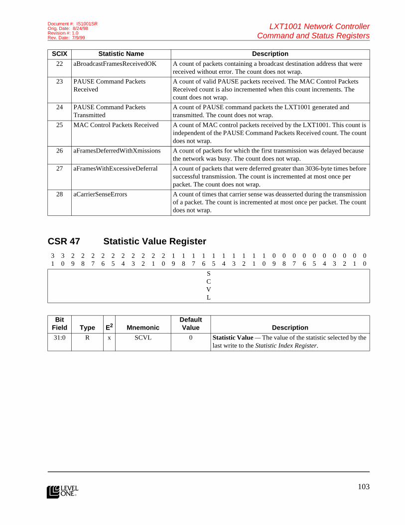
103
LXT1001 Network ControllerCommand and Status Registers
Document #: IS1001SROrig. Date: 8/24/98Revision #: 1.0Rev. Date: 7/9/99
l
CSR 47 Statistic Value Register
22 aBroadcastFramesReceivedOK A count of packets containing a broadcast destination address that were received without error. The count does not wrap.
23 PAUSE Command Packets Received
A count of valid PAUSE packets received. The MAC Control Packets Received count is also incremented when this count increments. The count does not wrap.
24 PAUSE Command Packets Transmitted
A count of PAUSE command packets the LXT1001 generated and transmitted. The count does not wrap.
25 MAC Control Packets Received A count of MAC control packets received by the LXT1001. This count is independent of the PAUSE Command Packets Received count. The count does not wrap.
26 aFramesDeferredWithXmissions A count of packets for which the first transmission was delayed because the network was busy. The count does not wrap.
27 aFramesWithExcessiveDeferral A count of packets that were deferred greater than 3036-byte times before successful transmission. The count is incremented at most once per packet. The count does not wrap.
28 aCarrierSenseErrors A count of times that carrier sense was deasserted during the transmission of a packet. The count is incremented at most once per packet. The count does not wrap.
31
30
29
28
27
26
25
24
23
22
21
20
19
18
17
16
15
14
13
12
11
10
09
08
07
06
05
04
03
02
01
00
SCVL
Bit Field Type E2 Mnemonic
Default Value Description
31:0 R x SCVL 0 Statistic Value — The value of the statistic selected by the last write to the Statistic Index Register.
SCIX Statistic Name Description

104l
LXT1001 Network ControllerCommand and Status Registers
Document #: IS1001SROrig. Date: 8/24/98
Revision #: 1.0Rev. Date: 7/9/99
Features (cont.)CSR 48 VLAN Tag Control Information Table
31
30
29
28
27
26
25
24
23
22
21
20
19
18
17
16
15
14
13
12
11
10
09
08
07
06
05
04
03
02
01
00
RESRVD
VLTBCM
RESRVD
VLTBIX
VLUSPR
RESRVD
VLID
Bit Field Type E2 Mnemonic
Default Value Description
11:0 W x VLID 0 VLAN Identifier — This field corresponds to the VLAN Identifier field in the VLAN tag header. When receiving a VLAN tagged packet, the LXT1001 uses this field to determine if the packet will be accepted or rejected.When the LXT1001 is inserting a VLAN tag header prior to packet transmission, this field is used in the construction of the VLAN tag header.
12 x x RESRVD 0 Reserved
15:13 W x VLUSPR 0 VLAN User Priority — The field corresponds to the user_priority field in the VLAN tag header. When receiving a VLAN tagged packet, the LXT1001 uses this field to determine if the packet will be accepted or rejected.When the LXT1001 is inserting a VLAN tag header prior to packet transmission, this field is used in the construction of the VLAN tag header.
19:16 W x VLTBIX 0 VLAN TCI Table Index — The index of the VLAN TCI Table entry to be acted upon by the command specified by VLTBCM. The TCI Table has 16 entries. The entry at index 0 is the “global” entry.
20 x x RESRVD 0 Reserved
21 W x VLTBCM 0 VLAN TCI Table Command — This bit indicates the operation to be performed on the VLAN TCI Tag Table. When set, the VLID and VLUSPR information is added to the table at the index specified by VLTBIX.When the VLTBCM bit is clear, the TCI information at index VLTBIX in the VLAN TCI Tag Table is deleted.
31:22 x x RESRVD 0 Reserved
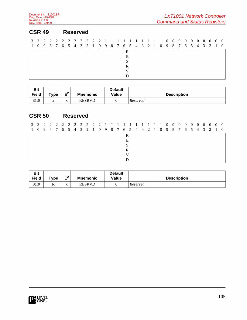
105
LXT1001 Network ControllerCommand and Status Registers
Document #: IS1001SROrig. Date: 8/24/98Revision #: 1.0Rev. Date: 7/9/99
l
CSR 49 Reserved
CSR 50 Reserved
31
30
29
28
27
26
25
24
23
22
21
20
19
18
17
16
15
14
13
12
11
10
09
08
07
06
05
04
03
02
01
00
RESRVD
Bit Field Type E2 Mnemonic
Default Value Description
31:0 x x RESRVD 0 Reserved
31
30
29
28
27
26
25
24
23
22
21
20
19
18
17
16
15
14
13
12
11
10
09
08
07
06
05
04
03
02
01
00
RESRVD
Bit Field Type E2 Mnemonic
Default Value Description
31:0 R x RESRVD 0 Reserved

106l
LXT1001 Network ControllerCommand and Status Registers
Document #: IS1001SROrig. Date: 8/24/98
Revision #: 1.0Rev. Date: 7/9/99
Features (cont.)CSR 51 Command Status Register
31
30
29
28
27
26
25
24
23
22
21
20
19
18
17
16
15
14
13
12
11
10
09
08
07
06
05
04
03
02
01
00
RESRVD
RXCMFECN
RESRVD
TXCMFECN
RXDMDNCN
TXDMDNCN
Bit Field Type E2 Mnemonic
Default Value Description
7:0 RC x TXDMDNCN 0 Transmit DMA Done Count — Indicates how many TX PDL/PDCs the LXT1001 has completed processing since the last read of this field. HOST software uses this count to determine when TX PDL/PDC buffers are no longer in use by the LXT1001. The LXT1001 resets the count after each read of this field.NOTE: This field can be accessed as a BYTE, WORD, or DWORD. A BYTE read of this field has no affect on other fields in the CSR. More specifically, the RXDMDNCN count is not changed by a BYTE access to this field.
15:8 RC x RXDMDNCN 0 Receive DMA Done Count — The count of RX PDL/PDCs the LXT1001 has completed processing since the last read of this field. HOST software uses this field to determine how many RX PDL/PDC buffers have been filled with receive data by the LXT1001. The LXT1001 resets the count to 0 after each read.NOTE: This field can be accessed as a BYTE, WORD, or DWORD. A BYTE read of this field has no affect on other fields in the CSR. More specifically, the TXDMDNCN count is not changed by a BYTE access to this field.NOTE: This field is aliased into the Event Status Register. Whether the count is read via the Command Status Register or the Event Status Register, the LXT1001 will reset the count after the read.
21:16 R x TXCMFECN 31 Transmit Command Free Count — This is the number of transmit command queue entries free in the chip. HOST software uses this field to determine how many additional transmit commands can be queued to the chip. The LXT1001 can queue a maximum of 31 transmit commands.
23:22 x x RESRVD 0 Reserved

107
LXT1001 Network ControllerCommand and Status Registers
Document #: IS1001SROrig. Date: 8/24/98Revision #: 1.0Rev. Date: 7/9/99
l
CSR 52 Flow Control Watermark Register
29:24 R x RXCMFECN 31 Receive Command Free Count — This is the number of receive command queue entries free in the chip. HOST software uses this field to determine how many additional receive commands can be queued to the chip. The LXT1001 can queue a maximum of 31 receive commands.
31:30 x x RESRVD 0 Reserved
31
30
29
28
27
26
25
24
23
22
21
20
19
18
17
16
15
14
13
12
11
10
09
08
07
06
05
04
03
02
01
00
FLCTHI
WM
FLCTLOWM
Bit Field Type E2 Mnemonic
Default Value Description
15:0 RW x FLCTLOWM 500h Flow Control Low Watermark — This field defines the flow control low watermark. The watermark is expressed in terms of the number of DWORDs in use in the RX FIFO.When the RX FIFO reaches the high flow control high watermark and then falls to the low watermark, the LXT1001 constructs and transmits a PAUSE frame with the pause duration set to 0. This PAUSE frame informs the link partner that the congested condition has subsided and it may begin transmitting immediately.
31:16 RW x FLCTHIWM 3B00h Flow Control High Watermark — This field defines the flow control high watermark. The watermark is expressed in terms of the number of DWORDs in use in the RX FIFO.When the RX FIFO reaches the high watermark, the LXT1001 constructs and transmits a PAUSE frame instructing the link partner to stop transmitting for 0FFFFh*512 bit times. As long as the RX FIFO stays above the low watermark, the LXT1001 sends additional PAUSE frames at an interval slightly less 0FFFFh*512 bit times. This has the effect of keeping the link partner paused.
Bit Field Type E2 Mnemonic
Default Value Description
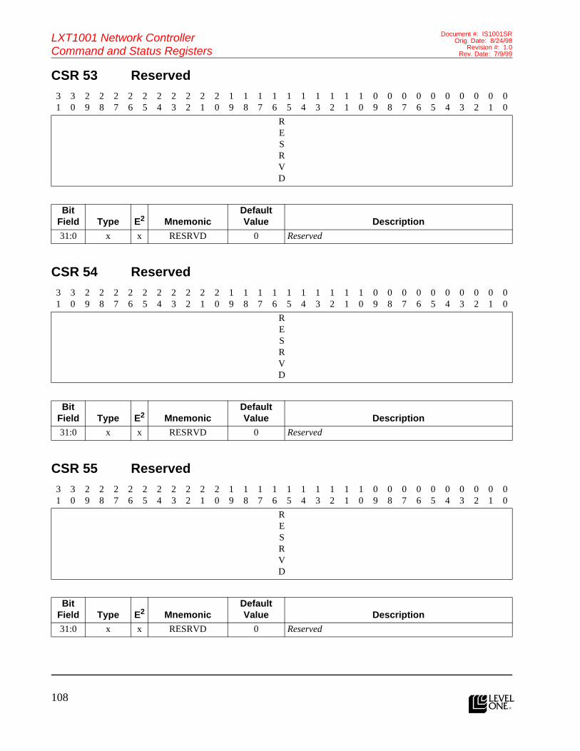
108l
LXT1001 Network ControllerCommand and Status Registers
Document #: IS1001SROrig. Date: 8/24/98
Revision #: 1.0Rev. Date: 7/9/99
Features (cont.)CSR 53 Reserved
CSR 54 Reserved
CSR 55 Reserved
31
30
29
28
27
26
25
24
23
22
21
20
19
18
17
16
15
14
13
12
11
10
09
08
07
06
05
04
03
02
01
00
RESRVD
Bit Field Type E2 Mnemonic
Default Value Description
31:0 x x RESRVD 0 Reserved
31
30
29
28
27
26
25
24
23
22
21
20
19
18
17
16
15
14
13
12
11
10
09
08
07
06
05
04
03
02
01
00
RESRVD
Bit Field Type E2 Mnemonic
Default Value Description
31:0 x x RESRVD 0 Reserved
31
30
29
28
27
26
25
24
23
22
21
20
19
18
17
16
15
14
13
12
11
10
09
08
07
06
05
04
03
02
01
00
RESRVD
Bit Field Type E2 Mnemonic
Default Value Description
31:0 x x RESRVD 0 Reserved

109
LXT1001 Network ControllerCommand and Status Registers
Document #: IS1001SROrig. Date: 8/24/98Revision #: 1.0Rev. Date: 7/9/99
l
CSR 56 Reserved
CSR 57 Reserved
31
30
29
28
27
26
25
24
23
22
21
20
19
18
17
16
15
14
13
12
11
10
09
08
07
06
05
04
03
02
01
00
RESRVD
Bit Field Type E2 Mnemonic
Default Value Description
31:0 x x RESRVD 0 Reserved
31
30
29
28
27
26
25
24
23
22
21
20
19
18
17
16
15
14
13
12
11
10
09
08
07
06
05
04
03
02
01
00
RESRVD
Bit Field Type E2 Mnemonic
Default Value Description
31:0 x x RESRVD 0 Reserved
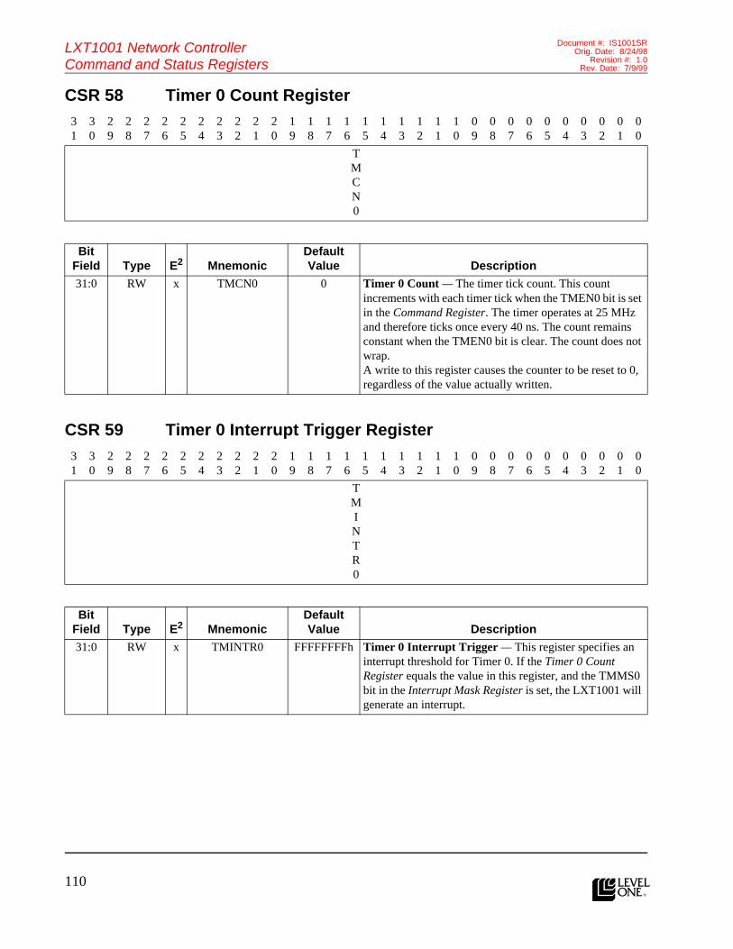
110l
LXT1001 Network ControllerCommand and Status Registers
Document #: IS1001SROrig. Date: 8/24/98
Revision #: 1.0Rev. Date: 7/9/99
Features (cont.)CSR 58 Timer 0 Count Register
CSR 59 Timer 0 Interrupt Trigger Register
31
30
29
28
27
26
25
24
23
22
21
20
19
18
17
16
15
14
13
12
11
10
09
08
07
06
05
04
03
02
01
00
TMCN0
Bit Field Type E2 Mnemonic
Default Value Description
31:0 RW x TMCN0 0 Timer 0 Count — The timer tick count. This count increments with each timer tick when the TMEN0 bit is set in the Command Register. The timer operates at 25 MHz and therefore ticks once every 40 ns. The count remains constant when the TMEN0 bit is clear. The count does not wrap. A write to this register causes the counter to be reset to 0, regardless of the value actually written.
31
30
29
28
27
26
25
24
23
22
21
20
19
18
17
16
15
14
13
12
11
10
09
08
07
06
05
04
03
02
01
00
TMINTR0
Bit Field Type E2 Mnemonic
Default Value Description
31:0 RW x TMINTR0 FFFFFFFFh Timer 0 Interrupt Trigger — This register specifies an interrupt threshold for Timer 0. If the Timer 0 Count Register equals the value in this register, and the TMMS0 bit in the Interrupt Mask Register is set, the LXT1001 will generate an interrupt.

111
LXT1001 Network ControllerCommand and Status Registers
Document #: IS1001SROrig. Date: 8/24/98Revision #: 1.0Rev. Date: 7/9/99
l
CSR 60 Timer 1 Count Register
CSR 61 Timer 1 Interrupt Trigger Register
31
30
29
28
27
26
25
24
23
22
21
20
19
18
17
16
15
14
13
12
11
10
09
08
07
06
05
04
03
02
01
00
TMCN1
Bit Field Type E2 Mnemonic
Default Value Description
31:0 RW x TMCN1 0 Timer 1 Count — The timer tick count. The count increments with each timer tick when the TMEN1 bit is set in the Command Register. The timer operates at 25 MHz and, therefore, ticks once every 40 ns. The count remains constant when the TMEN1 bit is clear. The count does not wrap. A write to this register causes the counter to be reset to 0, regardless of the value actually written.
31
30
29
28
27
26
25
24
23
22
21
20
19
18
17
16
15
14
13
12
11
10
09
08
07
06
05
04
03
02
01
00
TMINTR1
Bit Field Type E2 Mnemonic
Default Value Description
31:0 RW x TMINTR1 FFFFFFFFh Timer 1 Interrupt Trigger — This register specifies an interrupt threshold for Timer 1. If the Timer 1 Count Register equals the value in this register, and the TMMS1 bit in the Interrupt Mask Register is set, the LXT1001 will generate an interrupt.

112l
LXT1001 Network ControllerCommand and Status Registers
Document #: IS1001SROrig. Date: 8/24/98
Revision #: 1.0Rev. Date: 7/9/99
Features (cont.)CSR 62 Debug Command Register
CSR 63 Debug Data Register
31
30
29
28
27
26
25
24
23
22
21
20
19
18
17
16
15
14
13
12
11
10
09
08
07
06
05
04
03
02
01
00
DBST
RESRVD
BIST
Bit Field Type E2 Mnemonic
Default Value Description
0 W x BIST 0 Built In Self Test — This command causes the LXT1001 to perform a built-in self test (BIST). After issuing this command, HOST software polls the DBST until it clears. When the LXT1001 completes the BIST, it places the BIST completion code into the Debug Data Register and clears DBST. HOST software can then read the Debug Data Register to obtain the completion code for BIST. A 0 completion code indicates the BIST passed. A non-zero completion code indicates BIST failed.
30:1 x x RESRVD 0 Reserved
31 RA x DBST 0 Debug Status Bit — This bit is set by HOST software when writing to the Debug Address Register. When the requested action is complete, the LXT1001 clears the bit. HOST software polls this bit to determine when the command has completed.
31
30
29
28
27
26
25
24
23
22
21
20
19
18
17
16
15
14
13
12
11
10
09
08
07
06
05
04
03
02
01
00
DBDA
Bit Field Type E2 Mnemonic
Default Value Description
31:0 RW x DBDA 0 Debug Data Register — The value and interpretation of this field is dependent on the command issued in the Debug Command Register. Depending on the command issued, HOST software may need to write this register before issuing the command, or read this register after issuing the command.

113
LXT1001 Network ControllerCommand and Status Registers
Document #: IS1001SROrig. Date: 8/24/98Revision #: 1.0Rev. Date: 7/9/99
l
PCS Interface RegistersThe following register information is for the internal PCSInterface block management register set. The default valuesare those used by the PCS Interface block. Consult
individual PHY vendor’s documents for a list of theirmanagement registers and their default bit values.
Register 0 Control Register15
14
13
12
11
10
09
08
07
06
05
04
03
02
01
00
RST
LPBK
SPSEL
ANEN
PWRDN
ISLT
RSAN
FDMD
COLTST
GSPSEL
RESRVD
Bit Field Type Mnemonic
Default Value Description
5:0 RESRVD Reserved
6 R/W GSPSEL 1 Speed Selection 1000 Mb/s — The combination of SPSEL and GSPSEL determines the line rate in manual configuration. If ANEN bit is logic 1, SPSEL and GSPSEL are ignored. If ANEN bit is logic 0, SPSEL and GSPSEL set the line rate as follows:
GSPSEL SPSEL Line Rate1 1 Reserved1 0 1000 Mb/s0 1 100 Mb/s0 0 10 Mb/s
7 R/W COLTST 0 Collision Test — When set to logic 1, the PHY will assert the COL signal with 512 byte times after TX_EN is asserted and will de-assert the COL signal within 4 byte times after TX_EN is de-asserted. It is recommended that this bit be used only in conjunction with loopback operation.
8 R/W FDMD 1 Duplex Mode — If ANEN is logic 0, setting FDMD to logic 1 selects full duplex operation, and clearing it to logic0 selects half duplex operation. If ANEN is logic 1, the Auto-Negotiation will select the duplex mode and this bit is ignored.
9 R/W RSAN 0 Restart Auto-Negotiation — If ANEN is logic 0 or ANABL in the Status Register is logic 0, then RSAN is forced to logic 0 and any attempt to write it is ignored. Otherwise, the Auto-Negotiation process will be restarted when RSAN is set to logic 1. This bit is cleared when the Auto-Negotiation process is initiated.

114l
LXT1001 Network ControllerCommand and Status Registers
Document #: IS1001SROrig. Date: 8/24/98
Revision #: 1.0Rev. Date: 7/9/99
Features (cont.)10 R/W ISLT 1 Isolate — When set to logic 1, the outputs to the MAC
sub-layer are in a high impedance state, and the inputs from the MAC sub-layer are ignored. When cleared to logic 0, the PHY performsnormal operation. The management transactions via the management interface are not affected by ISLT.
11 R/W PWRDN 0 Power Down — When set to logic 1, the clocks from the PHY are invalid. When cleared to logic 0 and ISLT is logic 0, the PHY clocks are valid within 0.5 seconds. The management transactions via the management interface are not affected by PWRDN.
12 R/W ANEN 1 Auto-Negotiation Enable — When set to logic 1, the Auto-Negotiation process is enabled, and the SPSEL, GSPSEL, and FDMD bits are ignored.
13 R/W SPSEL 0 Speed Selection — The combination of SPSEL and GSPSEL determines the line rate in manual configuration. If ANEN bit is logic 1, SPSEL and GSPSEL are ignored. If ANEN bit is logic 0, SPSEL and GSPSEL set the line rate as follows:
GSPSEL SPSEL Line Rate1 1 Reserved1 0 1000 Mb/s0 1 100 Mb/s0 0 10 Mb/s
14 R/W LPBK 0 Loopback — When set to logic 1, the transmit data is looped back to the receive data in the PHY device. The transmit data is isolated from the line.
15 R/W RST 0 Reset — When set to logic 1, the control and status registers are set to their default states. The reset process shall be completed within 0.5 s from the setting of this bit.
Bit Field Type Mnemonic
Default Value Description

115
LXT1001 Network ControllerCommand and Status Registers
Document #: IS1001SROrig. Date: 8/24/98Revision #: 1.0Rev. Date: 7/9/99
l
Register 1 Status Register15
14
13
12
11
10
09
08
07
06
05
04
03
02
01
00
100T4
100XFD
100XHD
10FD
10HD
100T2FD
100T2FD
EXTSTS
RESRVD
MFPRESUP
ANDONE
RFLT
ANABL
LNKSTS
JABDET
EXTCAP
Bit Field Type Mnemonic
Default Value Description
0 RO EXTCAP 1 Extended Capability — When set to logic 1, the PHY has extended register capabilities.
1 RO JABDET 0 Jabber Detect — When set to logic 1, a jabber condition has been detected. This bit is forced to logic 0 for network speeds greater than 10 Mb/s.
2 RO LNKSTS X Link Status — When set to logic 1, the link is able to transmit data. When set to logic 0, the link is in configuration or idle mode.
3 RO ANABL 1 Auto-Negotiation Ability — When set to logic 1, the PHY is able to perform Auto-Negotiation.
4 RO RFLT x Remote Fault — When set to logic 1, a remote fault condition has been detected.
5 RO ANDONE x Auto-Negotiation Complete — When set to logic 1, Auto-Negotiation or Link Configuration process is complete.
6 RO MFPRESUP 1 MF Preamble Suppression — When set to logic 1, PHY will accept management frames with preamble suppressed.
7 RESRVD Reserved
8 RO EXTSTS 1 Extended Status — When set to logic 1, extended status information for GMII is stored in Extended Status Register.
9 RO 100T2HD 0 100BASE-T2 Half Duplex — When set to logic 1, the PHY is able to perform half duplex 100BASE-T2.
10 RO 100T2FD 1 100BASE-T2 Full Duplex — When set to logic 1, the PHY is able to perform full duplex 100BASE-T2.
11 RO 10HD 0 10 Mb/s Half Duplex — When set to logic 1, the PHY is able to operate at 10 Mb/s in half duplex mode.
12 RO 10FD 0 10 Mb/s Full Duplex — When set to logic 1, the PHY is able to operate at 10 Mb/s in full duplex mode.
13 RO 100XHD 0 100BASE-X Half Duplex — When set to logic 1, the PHY is able to perform half duplex 100BASE-X.

116l
LXT1001 Network ControllerCommand and Status Registers
Document #: IS1001SROrig. Date: 8/24/98
Revision #: 1.0Rev. Date: 7/9/99
Features (cont.)
Register 2 & 3 PHY Identifier Register
Register 4 Auto-Negotiation Advertisement Register
14 RO 100XFD 0 100BASE-X Full Duplex — When set to logic 1, the PHY is able to perform full duplex 100BASE-X.
15 RO 100T4 0 100BASE-T4 — When set to logic 1, the PHY is able to perform 100BASE-T4.
31
30
29
28
27
26
25
24
23
22
21
20
19
18
17
16
15
14
13
12
11
10
09
08
07
06
05
04
03
02
01
00
OUI
MMN
REV
Bit Field Type Mnemonic
Default Value Description
3:0 RO REV 0 Revision Number — For the internal PCS, the current revision number is ‘h0.
9:4 RO MMN 00 Manufacturer’s Model Number
31:11 RO OUI 00E083 Organizationally Unique Identifier — The OUI for Level One Communications is 00E083. External GMII/MII PHYs may have their own OUIs.
15
14
13
12
11
10
09
08
07
06
05
04
03
02
01
00
NXPG
RESRVD
RFLT
RESRVD
PS
HDP
FDP
RESRVD
Bit Field Type Mnemonic
Default Value Description
4:0 RO RESRVD Reserved
5 R/W FDP 1 Full Duplex — If set to logic 1, the Local Device is capable of full duplex operation. If cleared to logic 0, the Local Device is incapable of full duplex operation.
6 R/W HDP 1 Half Duplex — If set to logic 1, the Local Device is capable of half duplex operation. If cleared to logic 0, the Local Device is incapable of half duplex operation.
Bit Field Type Mnemonic
Default Value Description

117
LXT1001 Network ControllerCommand and Status Registers
Document #: IS1001SROrig. Date: 8/24/98Revision #: 1.0Rev. Date: 7/9/99
l
Register 5 Auto-Negotiation Link Partner Base Page Ability Register
8:7 R/W PS 11 Pause — PS provides a pause capability exchange mechanism.
[8] [7] Description0 0 No pause0 1 Symmetric pause1 0 Asymmetric pause1 1 Pause toward local device
11:9 RO RESRVD Reserved
13:12 R/W RFLT 0 Remote Fault — RFLT provides a mechanism for the transmission of simple fault and error inofrmation and may indicate to the Link Partner that a fult or error condition has occurred.
[13] [12] Description0 0 No error, link okay0 1 Link failure1 0 Offline1 1 Auto-Negotiation error
14 RO RESRVD Reserved
15 R/W NXPG 0 Next Page Ability — Set to logic 1 to indicate to the Link Partner that the Local Device is capable of handling next pages and that it has subsequent pages to be transmitted. Cleared to logic 0 to indicate that there is no next page information to be sent.
15
14
13
12
11
10
09
08
07
06
05
04
03
02
01
00
NXPG
ACK
RFLT
RESRVD
PS
HDP
FDP
RESRVD
Bit Field Type Mnemonic
Default Value Description
4:0 RO RESRVD Reserved
5 R/W FDP X Full Duplex — If set to logic 1, the Local Device is capable of full duplex operation. If cleared to logic 0, the Local Device is incapable of full duplex operation.
6 R/W HDP X Half Duplex — If set to logic 1, the Local Device is capable of half duplex operation. If cleared to logic 0, the Local Device is incapable of half duplex operation.
Bit Field Type Mnemonic
Default Value Description

118l
LXT1001 Network ControllerCommand and Status Registers
Document #: IS1001SROrig. Date: 8/24/98
Revision #: 1.0Rev. Date: 7/9/99
Features (cont.)
Register 6 Auto-Negotiation Expansion Register
8:7 R/W PS X Pause — PS provides a pause capability exchange mechanism.
[8] [7] Description0 0 No pause0 1 Symmetric pause1 0 Asymmetric pause1 1 Pause toward local device
11:9 RO RESRVD Reserved
13:12 R/W RFLT X Remote Fault — RFLT provides a mechanism for the transmission of simple fault and error inofrmation and may indicate to the Link Partner that a fult or error condition has occurred.
[13] [12] Description0 0 No error, link okay0 1 Link failure1 0 Offline1 1 Auto-Negotiation error
14 RO ACK X Acknowledge — ACK is set to logic 1 to indicate that the Link Partner has successfully received the Local Device’s base page.
15 R/W NXPG X Next Page Ability — Set to logic 1 to indicate to the Link Partner that the Local Device is capable of handling next pages and that it has subsequent pages to be transmitted. Cleared to logic 0 to indicate that there is no next page information to be sent.
15
14
13
12
11
10
09
08
07
06
05
04
03
02
01
00
RESRVD
NPABLE
PGRCVD
RESRVD
Bit Field Type Mnemonic
Default Value Description
0 RO RESRVD Reserved
1 ROSC
PGRCVD 0 Page Received — PGRCVD is set to logic 1 if a new page has been received and stored in either the link partner ability base or next page register. This bit is cleared to logic 0 upon a read of this register.
Bit Field Type Mnemonic
Default Value Description

119
LXT1001 Network ControllerCommand and Status Registers
Document #: IS1001SROrig. Date: 8/24/98Revision #: 1.0Rev. Date: 7/9/99
l
Register 7 Auto-Negotiation Next Page Transmit Register
2 RO NPABLE 1 Next Page Able — When read as logic 1, NPABLE indicates that the Local Device is capable of handling next pages. When read as logic 0, NPABLE indicates that the Local Device cannot perform next pages.
15:3 RO RESRVD Reserved
15
14
13
12
11
10
09
08
07
06
05
04
03
02
01
00
NXPG
RESRVD
MSPG
ACK2
TOG
MUCF
Bit Field Type Mnemonic
Default Value Description
10:0 R/W MUCF 0 Message/Unformatted Code Field — If MSPG is set to logic 1, the MUCF contains one of 2048 possible messages. If MSPG is set to logic 0, the MUCF may contin an arbitrary value.
11 RO TOG 0 Toggle — TOG is used to ensure synchronization with the Link Partner during next page exchange. This bit is set to logic 1 if the previous value transmitted was logic 0. This bit is cleared to logic 0 if the previous value transmitted was a logic 1.
12 R/W ACK2 0 Acknowledge 2 — Set to logic 1 to indicate that the Local Device will comply with the message. Cleared to logic 0 to indicate that the Local Device cannot comply with this message.
13 R/W MSPG 0 Message Page — This bit is set to logic 1 to indicate a message page. This bit is cleared to logic 0 to indicate an unformatted page.
14 RO RESRVD Reserved
15 R/W NXPG 0 Next Page — Set to logic 1 to indicate subsequent pages to be transmitted. This bit is cleared to logic 0 to indicate that there is no next page information to be sent.
Bit Field Type Mnemonic
Default Value Description

120l
LXT1001 Network ControllerCommand and Status Registers
Document #: IS1001SROrig. Date: 8/24/98
Revision #: 1.0Rev. Date: 7/9/99
Features (cont.)Register 8 Auto-Negotiation Link Partner Received Next Page Register
15
14
13
12
11
10
09
08
07
06
05
04
03
02
01
00
NXPG
RESRVD
MSPG
ACK2
TOG
MUCF
Bit Field Type Mnemonic
Default Value Description
10:0 RO MUCF X Message/Unformatted Code Field — If MSPG is set to logic 1, the MUCF contains one of 2048 possible messages. If MSPG is set to logic 0, the MUCF may contin an arbitrary value.
11 RO TOG X Toggle — TOG is used to ensure synchronization with the Link Partner during next page exchange. This bit is set to logic 1 if the previous value transmitted was logic 0. This bit is cleared to logic 0 if the previous value transmitted was a logic 1.
12 RO ACK2 X Acknowledge 2 — Set to logic 1 to indicate that the Local Device will comply with the message. Cleared to logic 0 to indicate that the Local Device cannot comply with this message.
13 RO MSPG X Message Page — This bit is set to logic 1 to indicate a message page. This bit is cleared to logic 0 to indicate an unformatted page.
14 RO RESRVD Reserved
15 RO NXPG X Next Page — Set to logic 1 to indicate subsequent pages to be transmitted. This bit is cleared to logic 0 to indicate that there is no next page information to be sent.

121
LXT1001 Network ControllerCommand and Status Registers
Document #: IS1001SROrig. Date: 8/24/98Revision #: 1.0Rev. Date: 7/9/99
l
Register 15 Extended Status Register15
14
13
12
11
10
09
08
07
06
05
04
03
02
01
00
1000XFD
1000XHD
1000TFD
1000THD
RESRVD
Bit Field Type Mnemonic
Default Value Description
11:0 RO RESRVD Reserved
12 RO 1000THD 0 1000BASE-T Half Duplex — When set to logic 1, 1000THD indicates that the PHY has the ability to perform half-duplex 1000BASE-T signaling. When read as a logic 0, 1000THD indicates that the PHY is unable to perform half-duplex 1000BASE-T signaling.
13 RO 1000TFD 0 1000BASE-T Full Duplex — When set to logic 1, 1000TFD indicates that the PHY has the ability to perform full-duplex 1000BASE-T signaling. When read as a logic 0, 1000TFD indicates that the PHY is unable to perform full-duplex 1000BASE-T signaling.
14 RO 1000XHD 1 1000BASE-X Half Duplex — When set to logic 1, 1000XHD indicates that the PHY has the ability to perform half-duplex 1000BASE-X signaling. When read as a logic 0, 1000XHD indicates that the PHY is unable to perform half-duplex 1000BASE-X signaling.
15 RO 1000XFD 1 1000BASE-X Full Duplex — When set to logic 1, 1000XFD indicates that the PHY has the ability to perform full-duplex 1000BASE-X signaling. When read as a logic 0, 1000XFD indicates that the PHY is unable to perform full-duplex 1000BASE-X signaling.

122l
LXT1001 Network ControllerCommand and Status Registers
Document #: IS1001SROrig. Date: 8/24/98
Revision #: 1.0Rev. Date: 7/9/99
Features (cont.)Vendor Specific Registers
Register 16 Level One Communications Features Register15
14
13
12
11
10
09
08
07
06
05
04
03
02
01
00
RESRVD
PSRS
Bit Field Type Mnemonic
Default Value Description
0 R/W PSRS Pause Resolution — When set to logic 1, pause resolution is used in priority resolution and the setting of the remote fault bits and the remote fault indication. When cleared to logic 0, pause resolution is not used in priority resolution.
15:1 RO RESRVD Reserved
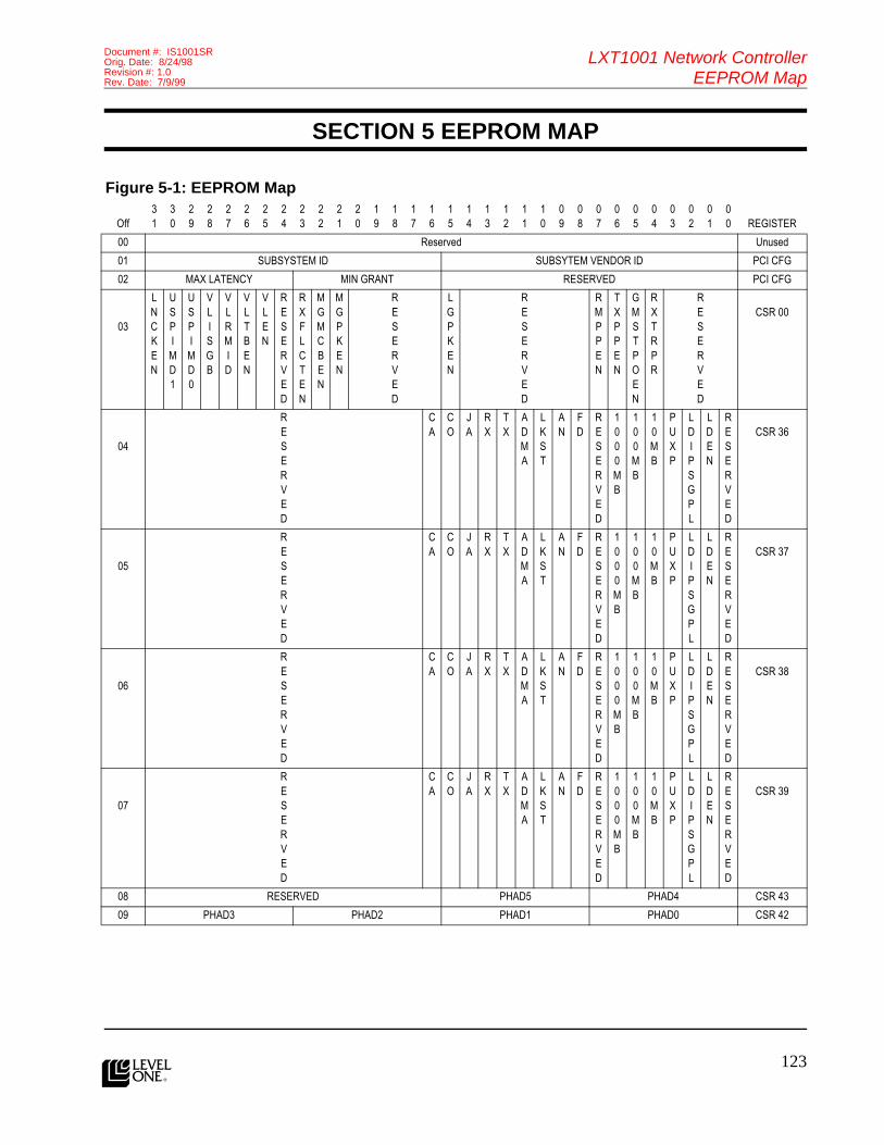
123
LXT1001 Network ControllerEEPROM Map
Document #: IS1001SROrig. Date: 8/24/98Revision #: 1.0Rev. Date: 7/9/99
l
SECTION 5 EEPROM MAP
Figure 5-1: EEPROM Map
Off31
30
29
28
27
26
25
24
23
22
21
20
19
18
17
16
15
14
13
12
11
10
09
08
07
06
05
04
03
02
01
00 REGISTER
00 Reserved Unused
01 SUBSYSTEM ID SUBSYTEM VENDOR ID PCI CFG
02 MAX LATENCY MIN GRANT RESERVED PCI CFG
03
LNCKEN
USPIMD1
USPIMD0
VLISGB
VLRMID
VLTBEN
VLEN
RESERVED
RXFLCTEN
MGMCBEN
MGPKEN
RESERVED
LGPKEN
RESERVED
RMPPEN
TXPPEN
GMSTPOEN
RXTRPR
RESERVED
CSR 00
04
RESERVED
CA
CO
JA
RX
TX
ADMA
LKST
AN
FD
RESERVED
1000MB
100MB
10MB
PUXP
LDIPSGPL
LDEN
RESERVED
CSR 36
05
RESERVED
CA
CO
JA
RX
TX
ADMA
LKST
AN
FD
RESERVED
1000MB
100MB
10MB
PUXP
LDIPSGPL
LDEN
RESERVED
CSR 37
06
RESERVED
CA
CO
JA
RX
TX
ADMA
LKST
AN
FD
RESERVED
1000MB
100MB
10MB
PUXP
LDIPSGPL
LDEN
RESERVED
CSR 38
07
RESERVED
CA
CO
JA
RX
TX
ADMA
LKST
AN
FD
RESERVED
1000MB
100MB
10MB
PUXP
LDIPSGPL
LDEN
RESERVED
CSR 39
08 RESERVED PHAD5 PHAD4 CSR 43
09 PHAD3 PHAD2 PHAD1 PHAD0 CSR 42
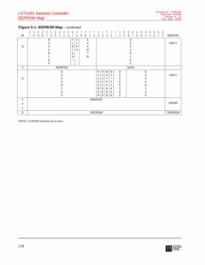
124l
LXT1001 Network ControllerEEPROM Map
Document #: IS1001SROrig. Date: 8/24/98
Revision #: 1.0Rev. Date: 7/9/99
Features (cont.)
*NOTE: FLWTEN must be set to zero.
10
RESERVED
FLWTEN*
FLPN
EXRMTM
RESERVED
CSR 10
11 RESERVED 0x8100
12
RESERVED
PACKEREN
RXUPCKEN
RXTPCKEN
RXIPCKEN
RESERVED
RESERVED
CSR 01
•••
RESERVEDUNUSED
31 CHECKSUM CHECKSUM
Figure 5-1: EEPROM Map – continued
Off31
30
29
28
27
26
25
24
23
22
21
20
19
18
17
16
15
14
13
12
11
10
09
08
07
06
05
04
03
02
01
00 REGISTER

125
LXT1001 Network ControllerGlossary
Document #: IS1001SROrig. Date: 8/24/98Revision #: 1.0Rev. Date: 7/9/99
l
SECTION 6 GLOSSARY
Symbol Description
AB Arbitrate
AC Acceptable
AD Address
AL Alignment
AN Auto Negotiation
AV Available
BC Broadcast
BF Buffer
BK Back
BT Byte
BU Bus
CA Carrier
CD Code
CK Check
CL Control
CM Command
CN Count
CO Collision
CR Cyclic Redundancy Check (CRC)
CS Chip Select
CT Control
DA Data
DB Debug
DE Descriptor
DF Defined
DL Delayed
DM Direct Memory Access. Refers to transactions initiated by the LXT1001 on the HOST/LXT1001 interconnectbus portion directly attached to the LXT1001. For LXT1001, DMA refers to MASTER PCI cycles initiatedby the LXT1001.
DN Done
DR Dropped
DS Disable
DV Device
DW Double Words (4 bytes)
E2 Electrically Erasable (as in EEPROM)

126l
LXT1001 Network ControllerGlossary
Document #: IS1001SROrig. Date: 8/24/98
Revision #: 1.0Rev. Date: 7/9/99
Features (cont.)EM Empty
EN Enable
ER Error
EX Exhausted/Expired
FA Failure
FD Full Duplex
FE Free
FI FIFO
FL Flow
FR Frame
GM GMII
GN General
HD Header
HI High
HS Hash
HT Hit
HW Hardware
ID Identifier
IL Idle
IN Interrupt
IP Input or Internet Protocol (IP)
IS Insert
IX Index
JA Jabber
LA Layer
LD LED
LG Long
LK Link
LN Line
LO Low
LP Loop
LT Late
MA Match
MB Megabit
MC Multicast
MD Mode
MG Magic
MI MII
Symbol Description

127
LXT1001 Network ControllerGlossary
Document #: IS1001SROrig. Date: 8/24/98Revision #: 1.0Rev. Date: 7/9/99
l
MS Mask
MU Multiple
NV Invalidate
OD Order
OK Okay
OU Out
OV Over
PA Pause
PE Periodic
PD PDL or PDC
PH Physical
PI Pin
PK Packet
PL Polarity
PM PROM
PN Present
PO Promiscuous or Poll
PP Packet Pad
PR Priority
PS Pass
PT Pointer
PU Pulse
RD Read
RE Reset
RESRVD Reserved
RG Ring
RM ROM or Remove
RQ Request
RR Register
RT Retries
RU Runt
RV Revision
RX Receive
SC Statistic
SE Set
SG Signal
SI Single
SK Skip
Symbol Description

128l
LXT1001 Network ControllerGlossary
Document #: IS1001SROrig. Date: 8/24/98
Revision #: 1.0Rev. Date: 7/9/99
Features (cont.)SL Slave
SM Sum
SP Speed
SR Stretcher
ST State/Status
SW Software
SY Symbol
TB Table
TM Timer
TP Transmission Control Protocol (TCP)
TR Trigger
TS Test
TX Transmit
UC Unicast
UP User Datagram Protocol (UDP)
US User
VL Value or VLAN
WM Watermark
WR Wire
WT Write
XP Expander
Symbol Description
129
LXT1001 Network ControllerGlossary
Document #: IS1001SROrig. Date: 8/24/98Revision #: 1.0Rev. Date: 7/9/99
l

EAST WEST ASIA/PACIFIC EUROPE
Eastern Area Headquarters &Northeastern Regional Office
Western AreaHeadquarters
Asia / Pacific AreaHeadquarters
European Area Headquarters
234 Littleton Road, Unit 1AWestford, MA 01886USATel: (978) 692-1193Fax: (978) 692-1124
3375 Scott Blvd., #110Santa Clara, CA 95054USATel: (408) 496-1950Fax: (408) 496-1955
101 Thomson RoadUnited Square #08-01Singapore 307591ThailandTel: +65 353 6722Fax: +65 353 6711
Parc Technopolis-Bat. Zeta 3,avenue du Canada - Z.A. de CourtaboeufLes Ulis Cedex 91974FranceTel: +33 1 64 86 2828 Fax: +33 1 60 92 0608
North CentralRegional Office
South CentralRegional Office
Central Asia/PacificRegional Office
Central and Southern Europe Regional Office
One Pierce Place Suite 500EItasca, IL 60143USATel: (630) 250-6044Fax: (630) 250-6045
2340 E. Trinity Mills Road Suite 306Carrollton, TX 75006USATel: (972) 418-2956Fax: (972) 418-2985
12F-1, No. 128, Section 3Ming Sheng East RoadTaipei, TAIWAN, R.O.C.Tel: +886 2 2547 5227Fax: +886 2 2547 5228
Feringastrasse 6D-85774 Muenchen-Unterfoerhring, GermanyTel: +49 89 99 216 375Fax: +49 89 99 216 319
SoutheasternRegional Office
SouthwesternRegional Office
Northern Asia/Pacific Regional Office
Northern Europe Regional Office
4020 WestChase BlvdSuite 100Raleigh, NC 27607USATel: (919) 836-9798Fax: (919) 836-9818
28202 Cabot Road Suite 300Laguna Niguel, CA 92677USATel: (949) 365-5655Fax: (949) 365-5653
Nishi-Shinjuku, Mizuma Building 8F3-3-13, Nishi-Shinjuku, Shinjuku-KuTokyo, 160-0023 JapanTel: +81 3 3347-8630Fax: +81 3 3347-8635
Torshamnsgatan 35164/40 Kista/Stockholm,SwedenTel: +46 8 750 3980Fax: +46 8 750 3982
Latin/SouthAmerica9750 Goethe RoadSacramento, CA 95827USATel: (916) 855-5000Fax: (916) 854-1102
Revision Date Status
1.0 7/9/99 Product Release
InternationalThe Americas
Corporate Headquarters9750 Goethe RoadSacramento, California 95827Telephone: (916) 855-5000Fax: (916) 854-1101Web: www.level1.com
l
Copyright © 1999 Level One Communications, Inc. Specifications subject to change without notice.All rights reserved. Printed in the United States of America.PDS-T
The products listed in this publication are covered by one or more of the following patents. Additional patents pending.5,008,637; 5,028,888; 5,057,794; 5,059,924; 5,068,628; 5,077,529; 5,084,866; 5,148,427; 5,153,875; 5,157,690; 5,159,291; 5,162,746; 5,166,635; 5,181,228; 5,204,880; 5,249,183; 5,257,286; 5,267,269; 5,267,746; 5,461,661; 5,493,243; 5,534,863; 5,574,726; 5,581,585; 5,608,341; 5,671,249; 5,666,129; 5,701,099
Document #: IS1001SROrig. Date: 8/24/98
Revision #: 1.0Rev. Date: 7/9/99